Embed Size (px)
Citation preview
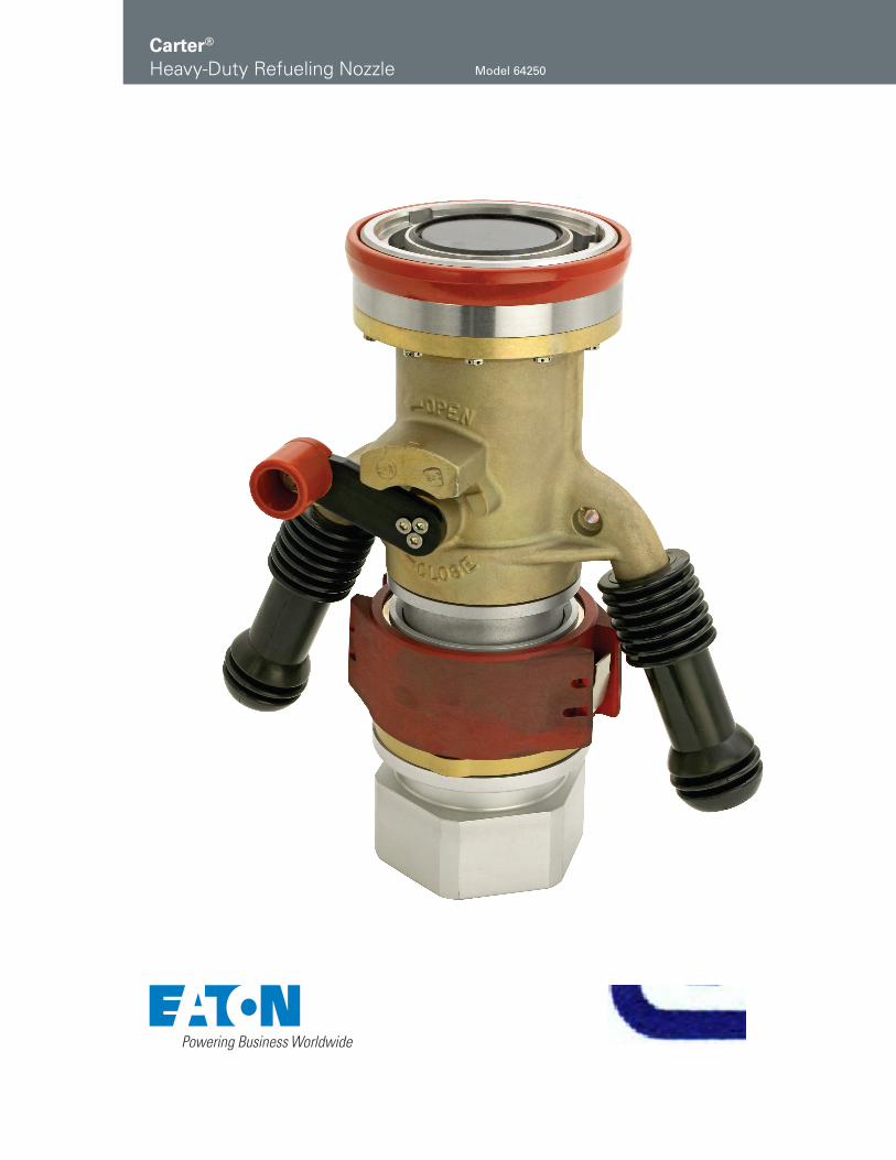
Carter®
Heavy-Duty Refueling Nozzle Model 64250

2 EATON Aerospace Group TF100-105D May 2013
Eaton’s Carter product line includes several standard underwing refueling nozzle models. A nozzle derived from earlier Model 64200 has been introduced, primarily for those airports that have extremely heavy-duty requirements. Model 64250 Heavy-Duty Refueling Nozzle, in addition to being designed for rugged, heavy-duty use, has several new features outlined below.
Features
y Easier swivelling under all conditions. Swivel independent of quick disconnect.
y Connects to 3-lug inter-national standard aircraft adapter
y Designed in accordance with new SAE design specification for commercial nozzles AS5877
y Self-adjusting pressure loaded nose seal. Leak free under extreme side loads, worn adapters and extreme temperatures.
y Uses same accessories as earlier 64200 and 64348 models. All accessories now have stainless steel wear ring in swivel ball joint.
y Lead-in ramps (interface with aircraft adapter lugs) of high strength aluminum for longer life
y Positive mechanical interlock — nozzle cannot be opened until connected to aircraft; cannot be removed from aircraft in open position
y Interlock mechanism internal to nozzle body
y No collar or other moving parts on exterior of nozzle with the exception of the operating lever
y Two threaded ports in nozzle body for simultaneous vacuum breaker and product sampling fitting installation are standard
y Lightweight and most rugged of any Eaton nozzle
y Modular construction with use of bolt flanges minimized
y 2, 2½ and 3-inch NPT and BSPP and 3-inch JIS threaded quick disconnect (QD) inlets available
y Optional 40, 60 & 100-mesh screens retained with snap rings for ease of removal
y Operating lever replaceable from exterior of nozzle and is made of less expensive, more ductile material. Also backed up with boss on nozzle body to prevent bending.
y 35 psi (2.413 bar), 45 psi (3.103 bar) & 55 psi (3.792 bar) Hose End Control Valves (HECV) available
y Dry break or ball valve for easy strainer inspection available
y Low pressure drop y Optional bonding cable and
vacuum breaker y Redundant safety lock on
the QD y Replaceable knob on operat-
ing handle eliminates razor sharp wear patterns preva-lent on competitor’s nozzles
y Options include a “U” bracket for nozzle stowage and one piece stirrup handle with stowage capability. No need to use an aircraft adapter as a stowage device.
Design Concepts
Envelope Dimensions
Dimensions shown in inches (millimeters)

EATON Aerospace Group TF100-105D May 2013 3
The part number for a com-plete nozzle consists of four parts as illustrated (right).
Ordering Data
Part 2
The following options may be added to part two of the part number to obtain the desired unit configuration.
64250
Part 1 - Model number
Part 2 - Option letter describing various changes to basic nozzle
Part 3 - Number and/or letter describing male adapter required to mate desired inlet configuration in Part 4 and/or ball valve type
Part 4 - Letter describing the inlet thread type and size
Option Description Option Description
*A Adds 40-mesh screen K Replaces standard operating handle with longer one
*B Adds 60-mesh screen L Replaces standard carrying handles with circular handleC Adds 100-mesh screen P Adds pressure gauge with protective bracketD Adds bonding cable Q Adds Gammon sampling quick disconnectE Adds vacuum breaker R Adds nozzle stowage bracket**F3 Adds 35 psi (2.413 bar) HECV S Adds 45° nozzle stowage bracket**F4 Adds 45 psi (3.103 bar) HECV T Adds adapter to mate Whittaker accessories**F5 Adds 55 psi (3.792 bar) HECV U Replaces standard handle with stirrup handlesG Replaces standard handles with long handles
(47233-2)V Replaces standard carrying handles with UK RAF style
handlesH Adds drag ring to nozzle with any Option F in
conjunction with Option T or Options 2 or 6 from Part 3 (220870)
W Adds military style bonding cable
J Inlet adapter to mate 60427 style outlet Y Adds swivel elbow
* Options A, B & C only available when a male half from Part 3 is specified ** To obtain a nozzle with a dual HECV setup specify two options in series, F5F4 results in 55 psi (3.792 bar) and 45 psi (3.103 bar)
units with the former assembled nearest the nozzle inlet. If two HECV’s are desired specify the highest pressure setting first.
Part 3
The configuration of the inlet is defined by adding the appropriate number(s) and/or letter(s) from the table below as Part 3 in conjunction with the appropriate option letter from Part 4.
Option Description Option Description
*1 Indicates nozzle with flanged inlet HECV R Adds defuel key to remove strainer cap to ball valve*2 Indicates nozzle with swivel inlet HECV 4 Adds male adapter half (44701 without HECV, 44185 with
flanged inlet HECV, 44697 with swivel inlet HECV) to mate basic nozzle and thumb latch QD
3 Adds ball valve (64015). Options D, E, J & R (below) may be added to complete the ball valve specification
6 Adds male adapter half to mate standard QD
D Adds glass inspection port to ball valve 7 Adds male adapter half (44697 without HECV, 44185 with flanged inlet HECV) to mate dry break QD
E Adds drag ring to ball valve 9 Adds male adapter half (43046 with flanged inlet HECV, 44362 otherwise) to mate 60427 style QD
J Adds spanner wrench to ball valve* If Option 1 or 2 is used with no additional options from Part 3, then the shortest configuration nozzle will be provided
Part 4
The following options may be added to obtain a female half, QD or dry break, or to complete the specification of the ball valve outlet. The nozzle may terminate in an adapter half only. In this case leave Part 4 blank.
Option Description Option Description
H Inlet thread — 2½-inch NPT N Inlet thread — 2-inch BSPPK Inlet thread — 2½-inch BSPP P Inlet thread — 2-inch NPT
L Inlet thread — 3-inch NPT Z Inlet thread — 3-inch JIS (used only with Options 6 and 9)
* M Inlet thread — 3-inch BSPP* Three-inch BSPP inlet threads not available with Option 3 Ball Valves
Examples:64250CD6H Nozzle with 100-mesh screen, bonding cable and standard QD with 2½-inch NPT inlet thread 64250BF41 Nozzle with 60-mesh screen, 45 psi (3.103 bar) HECV with inlet flange to mate 60427 type accessories.
Note that no inlet QD or other configuration is specified in this case.64250F517P Nozzle with 55 psi (3.792 bar) HECV with flanged adapter half and 61154 dry break QD with 2-inch NPT inlet.
Note: swivel adapter half and 61154 dry break QD can be specified by using 64250F527P.
4 EATON Aerospace Group TF100-105D May 2013
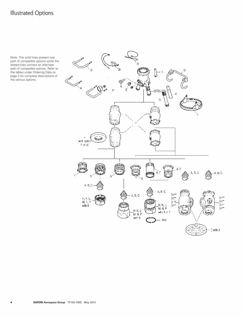
Note: The solid lines present one path of compatible options while the dotted lines connect an alternate path of compatible options. Refer to the tables under Ordering Data on page 3 for complete descriptions of the various options.
Illustrated Options

EATON Aerospace Group TF100-105D May 2013 5
Hose End Control Valves
The Hose End Control Valve (HECV) is designed to limit pressure at its outlet (at the pressure sensing port in the nozzle). The control pressure is a function of the main spring that loads the poppet. In addition to limiting pressure at the outlet, surge and lockup (no flow pressure) are also controlled. Refer to Model 60129-1 HECV brochure (TF100-76) for more details on how this is accomplished. The following characteristics are typical: y Normal spring setting
(maximum pressure limits will be 5 psi (0.345 bar) greater than spring) — 35 psi (2.413 bar), 45 psi (3.103 bar) and 55 psi (3.792 bar) available
y Surge pressure control — 75 psi (5.171 bar) maximum with 0.5 second valve closure (minimum)
y Lockup pressure — 10 psi (0.689 bar) maximum over spring setting for 45 psi and 55 psi HECVs; 20 psi (1.379 bar) maximum over spring setting for 35 psi unit
y Pressure limitation — 5 psi (0.345 bar) over spring setting with inlet pressure up to 100 psi (6.895 bar)
y Hysteresis (difference in pressure limits between increasing and decreasing flow rates) — pressure limits for decreasing flow rates will normally be slightly greater than for increasing flow rates
y Defueling is possible through unit. However, a blockout device is required to maintain maximum flow — use Eaton’s Model 61656 Blockout Device.
y Model 61656 Blockout Device recommended if system secondary control valve is to be checked
The curves presented below are typical for the inlet pressures and flow rates shown in a system with appropriate back pressure.
Curve 1 Control pressure with 100 psi (6.895 bar) inlet pressure
Curve 2 Control pressure with 90 psi (6.205 bar) inlet pressureCurve 3 Control pressure with 75 psi (5.171 bar) inlet pressure
55 psi HECV
40(2.758)
40(2.758)
40(2.758)
30(2.068)
30(2.068)
30(2.068)
20(1.379)
20(1.379)
20(1.379)
50(3.448)
50(3.448)
50(3.448)
60(4.137)
60(4.137)
60(4.137)
45 psi HECV
1
2
3
35 psi HECV
123
Ou
tlet
Pre
ssu
re-
psi(b
ar)
1
23
100(378)
200(757)
300(1,135)
400(1,514)
500(1,892)
600(2,271)
Flow Rate - USgpm (l/min)
100(378)
200(757)
300(1,135)
400(1,514)
500(1,892)
600(2,271)
Flow Rate - USgpm (l/min)
100(378)
200(757)
300(1,135)
400(1,514)
500(1,892)
600(2,271)
Flow Rate - USgpm (l/min)
Copyright © 2013 EatonAll Rights ReservedForm No. TF100-105DMay 2013
Eaton Aerospace Group 9650 Jeronimo Road Irvine, California 92618 Phone: (949) 452 9500 Fax: (949) 452 9555 www.eaton.com/aerospace
EatonAerospace GroupFluid & Electrical Distribution Division9650 Jeronimo RoadIrvine, California 92618Phone: (949) 452 9500Fax: (949) 452 9992E-Mail: [email protected]