Embed Size (px)
Citation preview

Cartesius-SD SeriesCartesian Robot User’s Manual
P/N: EDS141 (Revision 1.01.00)
Dedicated to the Science of MotionAerotech, Inc.101 Zeta Drive,Pittsburgh, PA, 15238Phone: 412-963-7470Fax: 412-963-7459www.aerotech.com

Product Registration Register online at: http://www.-aerotech.com/prodreg.cfm
Technical Support United States Headquarters:Phone: (412) 967-6440Fax: (412) 967-6870Email: [email protected] Kingdom:Phone: +44 118 940 9400Fax: +44 118 940 9401Email: [email protected]:Phone: +49 911 967 9370Fax: +49 911 967 93720Email: [email protected]:Phone: +81(0)47-489-1741 (Sales)Phone: +81(0)47-489-1742 (Service)Fax: +81(0)47-489-1743Email: [email protected]:Phone: +852-3793-3488Email: [email protected]
Revision History Revision 1.01.00 November 29, 2010Revision 1.00.00 February 13, 2009
Product names mentioned herein are used for identification purposes only andmay be trademarks oftheir respective companies.© Aerotech, Inc. 2010

Cartesius-SDSeries Stage User's Manual Table of Contents
Table of ContentsChapter 1: Overview 1
1.1. Standard Features 21.1.1. Optional Features 31.1.2. Model Numbers 5
1.2. Dimensions 71.3. Safety Procedures andWarnings 81.4. EC Declaration of Incorporation 10
Chapter 2: Installation 112.1. Unpacking and Handling the System 112.2. Preparing theMounting Surface 122.3. Shipping Brackets 132.4. Securing the System to theMounting Surface 142.5. Attaching the Payload to the System 152.6. Electrical Installation 16
2.6.1. Standard AerotechMotor Options 172.6.2. Optical Limit Switches 17
Chapter 3: Operating Specifications 193.1. Environmental Specifications 193.2. Accuracy and Temperature Effects 193.3. Basic Specifications 203.4. Load Capability 203.5. Optical Limit Switch 21
3.5.1. Limit Switch Operation 213.6. Limit SwitchWiring 223.7. StandardMotorWiring 233.8. VacuumOperation 27
3.8.1. Special Guidelines 27
Chapter 4: Maintenance 294.1. Service and Inspection Schedule 294.2. Cleaning and Lubrication 30
4.2.1. Recommended Lubricants and Cleaning Solvents 304.2.2. Important Notes on Lubrication 304.2.3. Lubrication and Cleaning Process 30
Appendix A: Warranty and Field Service 35Appendix B: Technical Changes 37Index 39Reader's Comments 41
www.aerotech.com iii

Table of Contents Cartesius-SDSeries Stage User's Manual
iv www.aerotech.com

Cartesius-SDSeries Stage User's Manual List Of Figures
List of FiguresFigure 1-1: Typical Cartesius-SD Series Cartesian Robot 1Figure 1-2: A single axis of the Cartesius-SD with Cutaway View of Ballscrew 2Figure 1-3: Right Hand XYZ with CableManagement System (top) and XY (bottom) Assemblies 3Figure 1-4: Left Hand XYZ (top) and XY (bottom) Assemblies 4Figure 1-5: Cartesius-SD Dimensions 7Figure 2-1: Results of Flat Versus Non-Flat Mounting 12Figure 2-2: Shipping Bracket Locations 13Figure 2-3: Mounting Hole Locations on X Axis 14Figure 2-4: Components of a Typical Stage 16Figure 3-1: Internal View of a Typical Stage Showing Limit Switches 21Figure 3-2: Series 9-pin Limit SwitchWiring 22Figure 3-3: Normally Closed (NC) and Normally Open (NO) Limit SwitchWiring 22Figure 3-4: Limit, Brake, and EncoderWiring for Standard Stages 23Figure 3-5: MotorWiring Connector for all Stages 25Figure 4-1: Y-axis Motor Cover 31Figure 4-2: Y-axis Motor Cover Removal Procedure 32Figure 4-3: Hardcover Removal Procedure (Step 1) 32Figure 4-4: Hardcover Removal Procedure (Step 2) 33Figure 4-5: Hardcover Removal Procedure (Step 3) 33
www.aerotech.com v

List of Figures Cartesius-SDSeries Stage User's Manual
vi www.aerotech.com

Cartesius-SDSeries Stage User's Manual List of Tables
List of TablesTable 1-1: Model Numbering System 5Table 2-1: StageMounting Surface Flatness Requirement 12Table 3-1: Environmental Specifications 19Table 3-2: Limit, Brake, and EncoderWiring Pinout Descriptions 24Table 3-3: MotorWiring Pinout Descriptions 25Table 3-4: Connectorized USER/IO Cable Pin Assignments 26Table B-1: Current Changes (1.01.00) 37Table B-2: Archived Changes 38
www.aerotech.com vii

List of Tables Cartesius-SDSeries Stage User's Manual
viii www.aerotech.com

Cartesius-SDSeries Stage User's Manual Overview
Chapter 1: OverviewThe Cartesius-SD series Cartesian robot is an industrial strength, multi-axis system that is built on the Aero-tech Producer Series linear ballscrew stages. It is ideal for many automation applications including pick andplace, assembly, test and inspection, dispensing stations, andmany more.
Chapter 1 shows a typical Cartesius-SD positioning system. For this manual, “X axis” will refer to the baseaxis, “Y axis” will refer to the cross axis, and “Z axis” will refer the vertical axis. The X, Y, and Z axes are com-prised of the PRO165, PRO115, and PRO115 respectively. The X and Y axes travel ranges from 150 to 600mm and the Z axis from 50mm to 300mm.
This chapter introduces standard and optional features of the Cartesius-SD series, explains themodel num-bering system, and gives general safety precautions.
Figure 1-1: Typical Cartesius-SD Series Cartesian Robot
NOTE : Aerotech continually improves its product offerings, and listed options may be superseded at anytime. Refer to themost recent edition of the AerotechMotion Control Product Guide for themost currentproduct information at www.aerotech.com.
www.aerotech.com Chapter 1 1

Overview Cartesius-SDSeries Stage User's Manual
1.1. Standard FeaturesA precision ground ballscrew and Linear Motion Guide (LMG) are standard features in all the axes of Car-tesius-SD. The precision-ground, preloaded ballscrews ensure superior positioning resolution and accuracywhile the LMG bearing systems provide stiffness, good load carrying capabilities, and continuous load sup-port over the entire range of travel.
Cartesius-SD also includes a complete cablemanagement system (CMS). Extensive R&D has resulted inan optimized CMS that has been field proven as the industry’s most reliable design. Large bend radii andhigh-flex cables ensure that Cartesius-SD provides millions of cycles of maintenance free operation. In theunlikely event of a failure, amodular design ensures that part replacement is fast and easy.
Other standard design features include integral hardcovers and side seals to keep contamination out of theinterior of the stages, and integral wipers on the ballscrew nut and bearing trucks to further reduce con-tamination. Optical limit switches andmechanical end stops, which protect themachine from over-travel,are also standard.
Figure 1-2: A single axis of the Cartesius-SD with Cutaway View of Ballscrew
2 Chapter 1 www.aerotech.com

Cartesius-SDSeries Stage User's Manual Overview
1.1.1. Optional Features
Available assembly options allow Cartesius-SD to be configured for a variety of applications.
Cartesius-SD can be configured in either a right hand (-RH) or left hand (-LH) orientation. The Z axis isoptional, so Cartesius-SD can bemade as an XY or XYZ system. The travels of each axis can bematched inany combination. The X and Y axes can use either a 5mm or 20mm lead ballscrew. The axes can also be pre-cision aligned to either 10 or 5 arc-sec orthogonality if needed. See Figure 1-3 and Figure 1-4 for examples ofdifferent arrangements available.
The stage table of the Y axis (or Z axis if ordered) is available with themounting holes and grid pattern ineither English (-TTU) or Metric (-TTM) dimensions.
Cartesius-SD systems can be ordered with a USER/IO option where Aerotech supplies (2) 6mm airlines and(1) 25 conductor signal cable through the stage cablemanagement to the stage tabletop for easy integration.The signal cable can be supplied connectorized or with flying leads.
For vacuum applications, two vacuum preparation options are available upon request; one compatible withlow vacuum environments (down to 10-3 torr) and the other for high vacuum (10-3 to 10-6 torr) applications.
Figure 1-3: Right Hand XYZ with Cable Management System (top) and XY (bottom) Assemblies
www.aerotech.com Chapter 1 3

Overview Cartesius-SDSeries Stage User's Manual
Figure 1-4: Left Hand XYZ (top) and XY (bottom) Assemblies
4 Chapter 1 www.aerotech.com

Cartesius-SDSeries Stage User's Manual Overview
1.1.2. Model Numbers
Systemmodel number example: CARTESIUS-SD-RH-X-20MM-300-Y-20MM-300-YCMS-Z-05MM-050-ZCMS-TTMZ-USER-IO-SUBD
The table below lists the available options in the order they appear in the example above. Aerotech con-tinually improves its product offerings, and listed options may be superseded at any time. Refer to themostrecent edition of the AerotechMotion Control Product Guide for themost current product information atwww.aerotech.com.
Table 1-1: Model Numbering System
Orientation-RH Right hand configuration-LH Left hand configuration
X Axis Options-X-20MM-150 150 mm (6 in) travel, 20mm lead ballscrew stage-X-20MM-200 200 mm (8 in) travel, 20mm lead ballscrew stage-X-20MM-250 250 mm (10 in) travel, 20mm lead ballscrew stage-X-20MM-300 300 mm (12 in) travel, 20mm lead ballscrew stage-X-20MM-400 400 mm (16 in) travel, 20mm lead ballscrew stage-X-20MM-500 500 mm (20 in) travel, 20mm lead ballscrew stage-X-05MM-250 250 mm (10 in) travel, 5mm lead ballscrew stage-X-05MM-300 300 mm (12 in) travel, 5mm lead ballscrew stage-X-05MM-400 400 mm (16 in) travel, 5mm lead ballscrew stage-X-05MM-500 500 mm (20 in) travel, 5mm lead ballscrew stage-X-05MM-600 600 mm (24 in) travel, 5mm lead ballscrew stage
Y Axis Options-Y-20MM-150 150 mm (6 in) travel, 20mm lead ballscrew stage-Y-20MM-200 200 mm (8 in) travel, 20mm lead ballscrew stage-Y-20MM-250 250 mm (10 in) travel, 20mm lead ballscrew stage-Y-20MM-300 300 mm (12 in) travel, 20mm lead ballscrew stage-Y-20MM-400 400 mm (16 in) travel, 20mm lead ballscrew stage-Y-20MM-500 500 mm (20 in) travel, 20mm lead ballscrew stage-Y-05MM-250 250 mm (10 in) travel, 5mm lead ballscrew stage-Y-05MM-300 300 mm (12 in) travel, 5mm lead ballscrew stage-Y-05MM-400 400 mm (16 in) travel, 5mm lead ballscrew stage-Y-05MM-500 500 mm (20 in) travel, 5mm lead ballscrew stage-Y-05MM-600 600 mm (24 in) travel, 5mm lead ballscrew stage-Y-20MM-150-YCMS 150 mm (6 in) travel, 20mm lead ballscrew stage and cable management-Y-20MM-200-YCMS 200 mm (8 in) travel, 20mm lead ballscrew stage and cable management-Y-20MM-250-YCMS 250 mm (10 in) travel, 20mm lead ballscrew stage and cable management-Y-20MM-300-YCMS 300 mm (12 in) travel, 20mm lead ballscrew stage and cable management
www.aerotech.com Chapter 1 5

Overview Cartesius-SDSeries Stage User's Manual
-Y-20MM-400-YCMS 400 mm (16 in) travel, 20mm lead ballscrew stage and cable management-Y-20MM-500-YCMS 500 mm (20 in) travel, 20mm lead ballscrew stage and cable management-Y-05MM-250-YCMS 250 mm (10 in) travel, 5mm lead ballscrew stage and cable management-Y-05MM-300-YCMS 300 mm (12 in) travel, 5mm lead ballscrew stage and cable management-Y-05MM-400-YCMS 400 mm (16 in) travel, 5mm lead ballscrew stage and cable management-Y-05MM-500-YCMS 500 mm (20 in) travel, 5mm lead ballscrew stage and cable management-Y-05MM-600-YCMS 600 mm (24 in) travel, 5mm lead ballscrew stage and cable managementZ Axis Options-NOZ No Z-axis-Z-05MM-050 50 mm (2 in) travel, 5mm lead ballscrew stage-Z-05MM-100 100 mm (4 in) travel, 5mm lead ballscrew stage-Z-05MM-150 150 mm (6 in) travel, 5mm lead ballscrew stage-Z-05MM-200 200 mm (8 in) travel, 5mm lead ballscrew stage-Z-05MM-250 250 mm (10 in) travel, 5mm lead ballscrew stage-Z-05MM-300 300 mm (12 in) travel, 5mm lead ballscrew stage-Z-05MM-050-ZCMS 50 mm (2 in) travel, 5mm lead ballscrew stage and cable management-Z-05MM-100-ZCMS 100 mm (4 in) travel, 5mm lead ballscrew stage and cable management-Z-05MM-150-ZCMS 150 mm (6 in) travel, 5mm lead ballscrew stage and cable management-Z-05MM-200-ZCMS 200 mm (8 in) travel, 5mm lead ballscrew stage and cable management-Z-05MM-250-ZCMS 250 mm (10 in) travel, 5mm lead ballscrew stage and cable management-Z-05MM-300-ZCMS 300 mm (12 in) travel, 5mm lead ballscrew stage and cable management
Tabletop Options-TTMY Metric hole-pattern tabletop for XY system-TTUY English hole-pattern tabletop for XY system-TTMZ Metric hole-pattern tabletop for XYZ system-TTUZ English hole-pattern tabletop for XYZ system
User I/O-USER-IO-NONE No User I/O option-USER-IO-DSUB (2) 6mm airlines and (1) customer I/O cable provided with mated 25 pin D connector at
the stage carriage-USER-IO-FLY 2) 6mm airlines and (1) customer I/O cable provided with flying leads at the stage car-
riage-USER-IO-ROTARY Wiring for rotary axis
Accessories (to be ordered as separate line item)ALIGNMENT-PA10 XY assembly; 10 arc sec orthogonalALIGNMENT-PA10Z XYZ assembly; 10 arc second orthogonalALIGNMENT-PA5 XY assembly; 5 arc sec orthogonalALIGNMENT-PA5Z XYZ assembly; 5 arc second orthogonalHDR165-100 Riser, 100mm TallHDR165-300 Riser, 300mm Tall
Table 1-1: Model Numbering System (continued)
6 Chapter 1 www.aerotech.com

Cartesius-SDSeries Stage User's Manual Overview
1.2. Dimensions
Figure 1-5: Cartesius-SD Dimensions
www.aerotech.com Chapter 1 7

Overview Cartesius-SDSeries Stage User's Manual
1.3. Safety Procedures and WarningsThe following statements apply throughout this manual. Failure to observe these precautions could result inserious injury to those performing the procedures and damage to the equipment.
This manual and any additional instructions included with the stage should be retained for the lifetime of thestage.
Tominimize the possibility of electrical shock and bodily injury or death, disconnect all elec-trical power prior to making any electrical connections.
Tominimize the possibility of electrical shock and bodily injury or death when any electricalcircuit is in use, ensure that no person comes in contact with the circuitry when the stage isconnected to a power source.
Tominimize the possibility of bodily injury or death, disconnect all electrical power prior tomaking any mechanical adjustments.
Moving parts of the stage can cause crushing or shearing injuries. All personnel mustremain clear of any moving parts.
Improper use of the stage can cause damage, shock, injury, or death. Read and understandthis manual before operating the stage.
If the stage is used in amanner not specified by the manufacturer, the protection providedby the stage can be impaired.
Stage cables can pose a tripping hazard. Securely mount and position all stage cables toavoid potential hazards.
8 Chapter 1 www.aerotech.com

Cartesius-SDSeries Stage User's Manual Overview
Do not expose the stage to environments or conditions outside the specified range of oper-ating environments. Operation in conditions other than those specified can cause damage tothe equipment.
The stagemust be mounted securely. Improper mounting can result in injury and damage tothe equipment.
Use care whenmoving the stage. Manually lifting or transporting stages can result in injury.
Only trained personnel should operate, inspect, andmaintain the stage.
This stage is intended for light industrial manufacturing or laboratory use. Use of the stagefor unintended applications can result in injury and damage to the equipment.
Before using this stage, perform an operator risk assessment to determine the neededsafety requirements.
www.aerotech.com Chapter 1 9

Overview Cartesius-SDSeries Stage User's Manual
1.4. EC Declaration of Incorporation
Manufactorer: Aerotech, Inc.101 Zeta DrivePittsburgh, PA 15238USA
herewith declares that the product:Aerotech, Inc. Cartesius-SD Stage
is intended to be incorporated into machinery to constitute machinery covered by the Directive2006/42/EC as amended;
does therefore not in every respect comply with the provisions of this directive;
and that the following harmonized European standards have been applied:EN ISO 12100-1,-2:2003+A1:2009Safety of machinery - Basic concepts, general principles for designISO 14121-1:2007Safety of machinery - Risk assessment - Par 1: PrinciplesEN 60204-1:2005Safety of machinery - Electrical equipment of machines - Part 1: General requirements
and further more declares thatit is not allowed to put the equipment into service until the machinery into which itis to be incorporated or of which it is to be a component has been found anddeclared to be in conformity with the provisions of the Directive 2006/42/EC andwith national implementing legislation, i.e. as a whole, including the equipmentreferred to in this Declaration.
Authorized Representative: Manfred BesoldAddress: AEROTECH GmbH
Süd-West-Park 90D-90449 Nürnberg
Name:
Alex Weibel /Position: Engineer Verifying ComplianceLocation: Pittsburgh, PADate: November 29, 2010
10 Chapter 1 www.aerotech.com
This is to certify that the aforementioned product is in accordance with the applicable requirements of the following Directive(s):
2011/65/EU RoHS 2 Directive

Cartesius-SDSeries Stage User's Manual Installation
Chapter 2: InstallationThis chapter describes the installation procedure for the Cartesius-SD stage, including handling the stageproperly, preparing themounting surface, securing the stage to themounting surface, attaching the payload,andmaking the electrical connections.
Installation must follow the instructions in this chapter. Failure to follow these instructionscould result in injury and damage to the equipment.
2.1. Unpacking and Handling the SystemCarefully remove the system from the protective shipping container. Use the provided eyebolt to lift theassembly. The lifting eyebolt should be removed before operating the system. Set the system on a smooth,flat, and clean surface. This is a simple, yet very important step inmaintaining the integrity of the system. Aleveling foot is attached to the Y axis bracket for support during shipping. The leveling foot must beremoved before operating the system. If any damage has occurred during shipping, report it immediately.
Each stage has a label listing the system part number and serial number. These numbers contain informationnecessary for maintaining or updating system hardware and software. Locate this label and record the infor-mation for later reference. If any damage has occurred during shipping, report it immediately.
Improper system handling could adversely affect the stage’s performance. Use care whenmoving the system. Manually lifting or transporting the system can result in injury.
Do not use the ballscrew ormotor as lifting points.
www.aerotech.com Chapter 2 11

Installation Cartesius-SDSeries Stage User's Manual
2.2. Preparing the Mounting SurfaceThemounting surface should be flat and have adequate stiffness in order to achieve themaximum per-formance from the Cartesius-SD. When a stage is mounted to a non-flat surface, the stage can be distortedas themounting screws are tightened. See Figure 2-1.
Figure 2-1: Results of Flat Versus Non-Flat Mounting
NOTE : Tomaintain accuracy, themounting surface should be flat, as specified in Table 2-1.
Any distortion will decrease the overall accuracy of the system. Aerotech recommends stoning themountingsurface and the X axis stage base with precision flat stones prior to mounting the system to themounting sur-face to remove any local high spots or imperfections in the surfaces. Adjustments to themounting surfacemust be done before the system is secured. If Aerotech HDR165 risers have been ordered as part of the Car-tesius system, in order to achieve desired accuracy, the flatness requirement must be observed as it wouldfor a standard X-axis stage.
NOTE : The stage base is precisionmachined and verified for flatness prior to stage assembly at the fac-tory. If machining is required to achieve the desired flatness, it should be performed on themounting sur-face rather than the stage base. Shimming should be avoided if possible. If shimming is required, it shouldbeminimized to improve the rigidity of the system.
Table 2-1: Stage Mounting Surface Flatness Requirement
X Axis Stage Travel Flatness Requiement150-300 mm 5 µm400-600 mm 7.5 µm
12 Chapter 2 www.aerotech.com

Cartesius-SDSeries Stage User's Manual Installation
2.3. Shipping BracketsCartesius-SD’s X axis comes equipped with shipping brackets. There are also shipping brackets on the Yaxis if it has a 20mm lead ballscrew. Both sets are shown in Figure 2-2.
Remove the shipping brackets once the stage has been placed on themounting surface. The X axis shippingbracket is composed of three pieces. Remove the vertical block at the opposite end of the X axis motor first.It is secured by twoM5x0.8 socket head cap screws (SHCS). Then, manually translate the X axis tableaway from themotor to access and remove the second vertical shipping block which is also secured by twoM5x0.8 SHCS. The shipping bracket base can then be removed by removing the four M4x0.7 SHCS.
The Y axis brackets aremounted in place with twoM4x0.7 socket head cap screws. Retain all shippingbrackets for future use.
Figure 2-2: Shipping Bracket Locations
www.aerotech.com Chapter 2 13

Installation Cartesius-SDSeries Stage User's Manual
2.4. Securing the System to the Mounting SurfaceIf necessary, manually move the X axis stage table to access the 6.5mm (0.28 in) diameter mounting holesalong the edges of the X axis stage (refer to Figure 2-3). This stage is designed to use socket head capscrews (SHCS) to secure the base to themounting surface. UseM6 x 22mm or 1/4 x 7/8” long SHCS toachieve 1.5x diameter thread engagement. Torque themounting screws to 8.1 N*m (6 ft*lb).
NOTE : The stage table may offer a considerable amount of resistance when it is movedmanually. This isespecially true if the stage is fitted with amotor assembly.
NOTE : If the stage is not connected to a power source, and not equipped with an optional brake, it shouldbe possible to move the stage table by hand with steady even pressure. Do not attempt to manually movethe stage if it is connected to a power source or includes an integrated brake.
The system must be mounted securely. Improper mounting can result in injury and damageto the equipment.
Figure 2-3: Mounting Hole Locations on X Axis
14 Chapter 2 www.aerotech.com

Cartesius-SDSeries Stage User's Manual Installation
2.5. Attaching the Payload to the SystemTo prevent damage to delicate payloads, test the operation of the system before attaching the payload to thetable. Proceed with the electrical installation and test themotion control system in accordance with the sys-tem documentation. Document all results for future reference. For information on electrical connections, referto Section 2.6. Electrical Installation.
The payload should be flat, rigid, and comparable to the system in quality.
NOTE : For valid accuracies, themounting interface should be flat within 1 µm per 50mm.
Do not attach a payload to the stage table with screws that are too long. A screw passingthrough the stage table can come into contact with the hardcover, affecting travel and pos-sibly damaging the stage.
www.aerotech.com Chapter 2 15

Installation Cartesius-SDSeries Stage User's Manual
2.6. Electrical InstallationElectrical installation requirements will vary depending on system options. Installation instructions in thissection are for systems equipped with standard Aerotechmotors intended for use with an Aerotechmotioncontrol system. Contact Aerotech for further information regarding systems that are otherwise configured.
Aerotechmotion control systems are adjusted at the factory for optimum performance. When the Cartesius-SD series system is part of a complete Aerotechmotion control system, setup involves connecting the sys-tem to the appropriate drive chassis with the cables provided. Connect the provided cables to themotor andfeedback connectors on the Cartesius-SD. Labels on the drive indicate the appropriate connections. Refer toyour drivemanuals and documentation for additional installation and operation information. In some cases, ifthe system is uniquely configured, a drawing showing system interconnects is supplied.
Never connect or disconnect any electrical component or connecting cable while power isapplied, or serious damagemay result.
The stage's protective ground is located on pin A4 of the motor connector. If you are usingcables other than those provided by Aerotech, you must connect pin A4 to a ground con-nection.
Figure 2-4: Components of a Typical Stage
16 Chapter 2 www.aerotech.com

Cartesius-SDSeries Stage User's Manual Installation
2.6.1. Standard Aerotech Motor Options
Aerotech’s high performance brushless rotary motors are the standardmotors for all axes of Cartesius-SD.The BM130 and BMS100 are standard for the X-axis (PRO165). The BM75 and BMS60 are the standardmotors for the Y and Z axes (PRO115), with the Z-axis motor always supplied with a brake. The electrical wir-ing from themotor and encoder to the “connectorized” ports on themotor can is contained within the rearmotor housing and has been completed at the factory. Themotor cables and limit cable convey motor power,encoder feedback, and limit switch signals to an appropriate hardware device (e.g. axis controller or ampli-fier). Refer to Section 3.7. for standardmotor wiring and connector pin outputs.
2.6.2. Optical Limit Switches
Each axis of Cartesius-SD is equipped with a pair of optical limit switches: one at each end of nominal travel.The limit switches can be configured as normally closed (NC) or normally open (NO). On the X axis stage,the limit cable exits the stage on the same side as themotor and is bundled with the other system cables. Forthe Y and Z axis stages, the limit cable is wired into the feedback cable. Refer to Section 3.6. for a descrip-tion of limit switch operation and wiring.
www.aerotech.com Chapter 2 17

Installation Cartesius-SDSeries Stage User's Manual
18 Chapter 2 www.aerotech.com

Cartesius-SDSeries Stage User's Manual Operating Specifications
Chapter 3: Operating SpecificationsThe surrounding environment and operating conditions can affect the performance and service life of the sys-tem. This chapter provides information on ideal environmental and operating conditions. Also included areinstructions for estimating load capability.
3.1. Environmental SpecificationsThe environmental specifications for the Cartesius-SD are listed in the following table.
Table 3-1: Environmental Specifications
AmbientTemperature
Operating: 10° to 35° C (50° to 95° F)The optimal operating temperature is 20° C ±2° C (68° F ±4° F). If at any time the operating tem-perature deviates from 20° C degradation in performance could occur. Contact Aerotech forinformation regarding your specific application and environment.Storage: 0° to 40° C (32° to 104° F) in original shipping packaging
Humidity Operating: 40 percent to 60 percent RHThe optimal operating humidity is 50 percent RH.Storage: 30 percent to 60 percent RH, non-condensing in original packaging
Altitude Operating: 0 to 2,000 m (0 to 6,562 ft) above sea levelContact Aerotech if your specific application involves use above 2,000 m or below sea level.
Vibration Use the system in a low vibration environment. Excessive floor or acoustical vibration can affectstage and system performance. Contact Aerotech for information regarding your specific appli-cation.
Dust Expo-sure
The Cartesius-SD has limited protection against dust, but not water. This equates to an ingressprotection rating of IP50.
Use Indoor use only
Do not expose the stage to environments or conditions outside the specified range of oper-ating environments. Operation in conditions other than those specified can cause damage tothe equipment.
3.2. Accuracy and Temperature EffectsThe accuracy specification of Cartesius-SD series robot is measured at the center of travel 25mm above thetable. The system is assumed to be fully supported by amounting surfacemeeting or exceeding the spec-ification in Table 2-1.
The accuracy of the ballscrew is a key element in the overall positioning accuracy. A scale error on each axiscan be expected if temperature of the ballscrew differs from 20° C (68° F). The greater the temperature dif-ference, the greater the error. The temperature of the ballscrew depends on the speed and duty cycle of theaxis. The faster themovement and higher the duty cycle, themore the stage accuracy will be affected byheat. The thermal expansion coefficient of the ballscrew is 11.7 ppm/°C.
www.aerotech.com Chapter 3 19

Operating Specifications Cartesius-SDSeries Stage User's Manual
3.3. Basic SpecificationsSpecifications for the Cartesius-SD series positioning system are not included in this manual. For moredetailed information, see the individual axis (PRO165 or PRO115)manuals.
3.4. Load CapabilityThe Cartesius-SD’s load capability will vary widely depending on the number of axes, the individual axes’lengths/leads, the payload’s size/location, and themove profile. Each case should be confirmed with Aero-tech as acceptable. For reference, all Cartesius-SD configurations can handle a centered (non-offset) 5 kgload. Systems with shorter travel axes or XY assemblies will have a greater load capability.
20 Chapter 3 www.aerotech.com

Cartesius-SDSeries Stage User's Manual Operating Specifications
3.5. Optical Limit SwitchEach Cartesius-SD axis is provided with a pair of optical limit switch assemblies mounted to the base of thestage. The limit switches signal when the axis has reached its maximum useable travel distance in both direc-tions.
3.5.1. Limit Switch Operation
Each limit switch has a light source and detector mounted to a small printed circuit board. Each limit switchboard is mounted at an end of the stage with its emitter–detector axes perpendicular to the direction of tablemotion. On a standard stage, the clockwise (CW) switch is located at the end opposite themotor. Whenmovement of the stage table causes the blademounted to the stage carriage to break the light beam from theemitter to the detector, a CW or counterclockwise (CCW) limit signal is generated. The limit switch itself canbe configured as normally closed (NC) or normally open (NO).
If the stage is driven past the electrical limit, it will encounter the hard stop. Where the hardlimit occurs is dependent on stage travel. Although the operating speed of the stagemay berelatively slow, and the stage’s shocks will provide some protection, damage to the stagecould result.
Figure 3-1: Internal View of a Typical Stage Showing Limit Switches
NOTE : Clockwise (CW) and counterclockwise (CCW) refer to the direction of motor rotation while lookinginto the shaft of themotor. CW rotation of themotor causes the stage table tomove away from themotor.CCW rotation of themotor causes the stage table tomove toward themotor.
www.aerotech.com Chapter 3 21

Operating Specifications Cartesius-SDSeries Stage User's Manual
3.6. Limit Switch WiringLimit switches are open-collector, TTL–compatible, electro–optical devices powered by 5 Volts that changeoutput states when the stage approaches its maximum travel distance and breaks the light beam. Since theyare open-collector devices, they may be interfaced to 24 Volt logic inputs. Each limit switch is mounted on asmall printed circuit board. Standard stages include wiring in a separate 9-pin limit switch connector, detailedin Figure 3-2.
Figure 3-2: Series 9-pin Limit Switch Wiring
Assuming a NC limit configuration, the input to the controller is seen as a logic 0 (typical 0.4V@ 12.8mA)when no limit condition is present. When the limit switch is activated, a 5V source through a pull-up resistor,on the controller, causes a logic 1 (typically 4.8-5 V) to be seen by the controller input. The limit switch oper-ation for a NO limit configuration is the exact opposite as described above. See Figure 3-3 for a diagram oflimit switch wiring.
Figure 3-3: Normally Closed (NC) and Normally Open (NO) Limit Switch Wiring
22 Chapter 3 www.aerotech.com

Cartesius-SDSeries Stage User's Manual Operating Specifications
3.7. Standard Motor WiringStages fitted with standardmotors and encoders come from the factory completely wired and assembled. Forreference, connector pin outputs and general wiring information is given in the following figures and tables.Pin outputs are defined in 3.7 and 3.7.
NOTE : Refer to the other documentation accompanying your Aerotech equipment. Call your Aerotech rep-resentative if there are any questions on system configuration.
NOTE : If you are using your own cables to connect the stage, ensure that motor and ground wires canhandle current higher than the continuous motor current listed in the individual axis (PRO165 or PRO115)manuals. The voltage rating of the wire insulationmust be higher than themaximum drive output voltagelisted in the individual axis (PRO165 or PRO115)manuals.
Figure 3-4: Limit, Brake, and Encoder Wiring for Standard Stages
www.aerotech.com Chapter 3 23

Operating Specifications Cartesius-SDSeries Stage User's Manual
Table 3-2: Limit, Brake, and Encoder Wiring Pinout Descriptions
Pin Output DescriptionBRAKE + Optional failsafe electro-magnetic brake +BRAKE - Optional failsafe electro-magnetic brake -CCW LMT Counter clockwise end-of-travel limit (optional)COS Cosine. Incremental encoder output; either TTL line driven or amplified sine wave type signal.COS-N Incremental encoder output. Complement of cos.CW LMT Clockwise end-of-travel limit (optional)ENC +5V +5 V supply input for optical encoders. Typical requirement is 250 mA.HA Hall Effect A. Brushless motor commutation track output. TTL line driven signal with rotary
motor.HB Hall Effect B. Brushless motor commutation track output. TTL line driven signal with rotary
motor.HC Hall Effect C. Brushless motor commutation track output. TTL line driven signal with rotary
motor.HOME LMT Homing cycle reference limit (optional)LMT +5v + 5 V supply input for optical limit switch boards. Typical requirement is 50 mA.LMT COM Common ground for limit switchMKR Marker. Incremental encoder output pulse given once per revolution. Typically used for home
reference cycle.MKR-N Incremental encoder output; either the compliment of Marker with a line driven, TTL type
encoder or 2.5 V DC bias level with amplified sine wave type encoder.SIN Sine. Incremental encoder output; either TTL line driven or amplified sign wave type signal.SIN-N Incremental encoder output. Complement of sin.
24 Chapter 3 www.aerotech.com

Cartesius-SDSeries Stage User's Manual Operating Specifications
Figure 3-5: Motor Wiring Connector for all Stages
Table 3-3: Motor Wiring Pinout Descriptions
Pin Output DescriptionFRM GND Ground to stage base.MTR SHLD Shield for motor wiring connector.MTR ØA Motor Phase A.MTR ØB Motor Phase B.MTR ØC Motor Phase C.
www.aerotech.com Chapter 3 25
Operating Specifications Cartesius-SDSeries Stage User's Manual
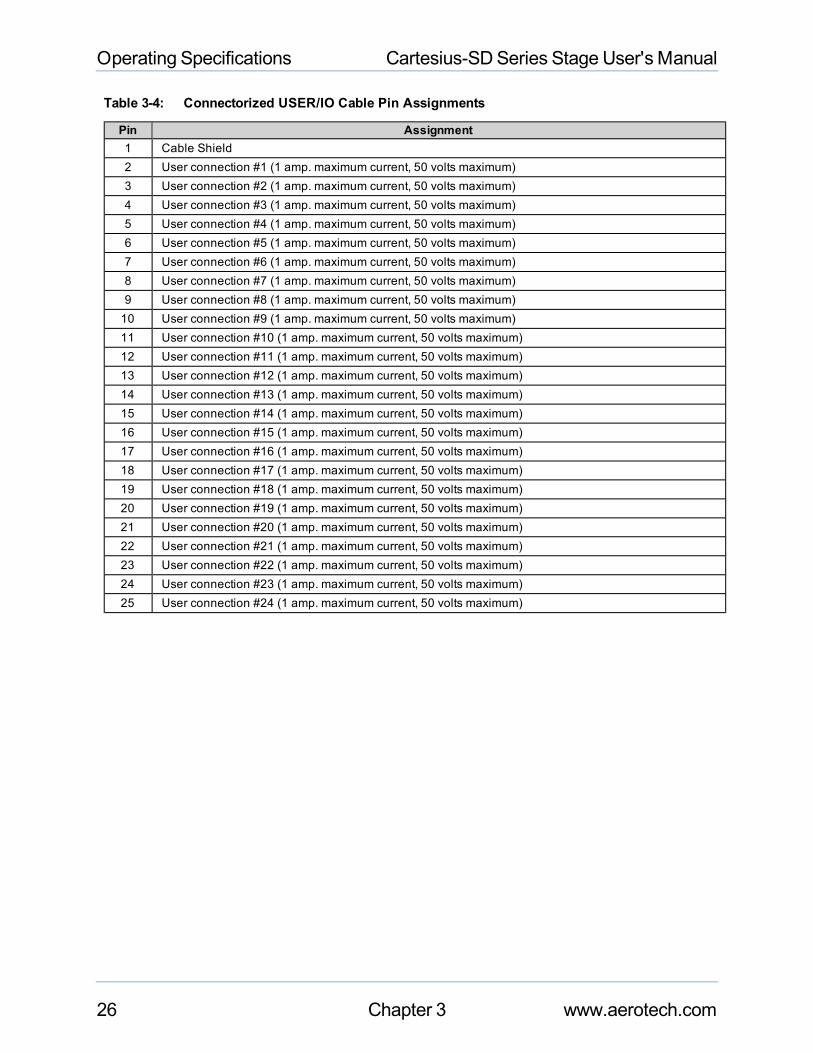
Table 3-4: Connectorized USER/IO Cable Pin Assignments
Pin Assignment1 Cable Shield2 User connection #1 (1 amp. maximum current, 50 volts maximum)3 User connection #2 (1 amp. maximum current, 50 volts maximum)4 User connection #3 (1 amp. maximum current, 50 volts maximum)5 User connection #4 (1 amp. maximum current, 50 volts maximum)6 User connection #5 (1 amp. maximum current, 50 volts maximum)7 User connection #6 (1 amp. maximum current, 50 volts maximum)8 User connection #7 (1 amp. maximum current, 50 volts maximum)9 User connection #8 (1 amp. maximum current, 50 volts maximum)10 User connection #9 (1 amp. maximum current, 50 volts maximum)11 User connection #10 (1 amp. maximum current, 50 volts maximum)12 User connection #11 (1 amp. maximum current, 50 volts maximum)13 User connection #12 (1 amp. maximum current, 50 volts maximum)14 User connection #13 (1 amp. maximum current, 50 volts maximum)15 User connection #14 (1 amp. maximum current, 50 volts maximum)16 User connection #15 (1 amp. maximum current, 50 volts maximum)17 User connection #16 (1 amp. maximum current, 50 volts maximum)18 User connection #17 (1 amp. maximum current, 50 volts maximum)19 User connection #18 (1 amp. maximum current, 50 volts maximum)20 User connection #19 (1 amp. maximum current, 50 volts maximum)21 User connection #20 (1 amp. maximum current, 50 volts maximum)22 User connection #21 (1 amp. maximum current, 50 volts maximum)23 User connection #22 (1 amp. maximum current, 50 volts maximum)24 User connection #23 (1 amp. maximum current, 50 volts maximum)25 User connection #24 (1 amp. maximum current, 50 volts maximum)
26 Chapter 3 www.aerotech.com

Cartesius-SDSeries Stage User's Manual Operating Specifications
3.8. Vacuum OperationAerotech can specially prepare the Cartesius-SD system for operation in vacuum environments. Aerotechoffers two vacuum preparation options; one for low vacuum (for use in atmospheric pressures to 10-3 torr) andone for high vacuum (preparation for environments from 10-3 to 10-6 torr). As part of this preparation, attentionto detail duringmodification, cleaning, and assembly results in stages with optimal performance in vacuumapplications. This section will outline preparation techniques for stages that will operate in a vacuum. Sometechniques covered are:
l Lubrication with vacuum–compatible lubricantsl Use of materials, fasteners, and coatings with vacuum outgas performance compatible with the level of
vacuum specifiedl For high vacuum stages, elimination of situations that may allow gases to become temporarily trapped
during pump downl Extensive cleaning prior to assembly in a clean environment and packaging in a special polyethylene bag
3.8.1. Special Guidelines
To ensure that the stage will continue to perform well in the vacuum environment, follow the guidelines listedbelow (in addition to standard handling, installation, and lubrication guidelines outlined earlier in this manual).
1. Do not remove the stage from the sealed bag until it is ready for use.2. Always handle the stage in a clean environment and use powder-free polyethylene gloves to prevent any
contaminants from adhering to the surface of the stage.3. During installation, use cleaned, vented, stainless steel fasteners when securing the stage.4. Reduced air pressure eliminates significant convective heat transfer. This, coupled with the viscous vac-
uum–compatible lubricants, could result in excessivemotor operating temperatures. Because of this,consider all continuous torque ratings to be 40 to 60% lower than the value specified for operation in nor-mal atmospheric environment. Reducemotor usage accordingly.
5. For vacuum applications, the recommended lubricant is a small quantity of Braycote® 602EF grease or asubstitute of equal quality.
Baking vacuum components between 100 and 125 °C for 24 to 48 hours significantly reduces outgassing atinitial pump-down to vacuum pressure and evaporates water vapor that impregnates porous surfaces on thealuminum surfaces and Teflon cables. Aerotech recommends that customers bake out vacuum systemswhen first installing them in the vacuum chamber.
www.aerotech.com Chapter 3 27

Operating Specifications Cartesius-SDSeries Stage User's Manual
28 Chapter 3 www.aerotech.com

Cartesius-SDSeries Stage User's Manual Maintenance
Chapter 4: MaintenanceThis chapter will cover information about intervals between lubrications, detail the lubrication and inspectionprocess, and cover which lubricants are recommended for use.
NOTE : The bearing areamust be kept free of foreignmatter andmoisture; otherwise, the performanceand life expectancy of the system will be reduced. Always operate the system with all hard covers and sideseals in place to help keep dirt out.
Tominimize the possibility of bodily injury, confirm that all electrical power is disconnectedprior to making any mechanical adjustments.
4.1. Service and Inspection ScheduleLubricant inspection and replenishment in the Cartesius-SD series systems depends on conditions such asduty cycle, speed, and the environment. An inspection interval of once per month is recommended until atrend develops for the application. Longer or shorter intervals may be required tomaintain the film of lubricanton the bearing surfaces. In general, it is recommended that stages operating in a clean environment be lubri-cated annually, or every 500 km, whichever comes first. For stages operating under conditions involvingexcessive debris, lubrication every six months is recommended. If the application process uses only a smallportion of travel for most of the duty cycle, it is recommended that the stage be periodically driven through fulltravel to redistribute the lubrication in the bearings and ballscrew. The ballscrew end bearings andmotor bear-ings are sealed, and should not need to be relubricated under normal use.
www.aerotech.com Chapter 4 29

Maintenance Cartesius-SDSeries Stage User's Manual
4.2. Cleaning and Lubrication
4.2.1. Recommended Lubricants and Cleaning Solvents
For standard ballscrew assemblies and LMG guide rails, THK AFE-CA grease is recommended.
If a solvent is necessary for cleaning the stage, it is recommended that isopropyl alcohol be used. Harshersolvents, such as acetone, may damage the plastic and rubber seals on the ballscrew nuts or LMG trucks. Ifacetone is required, avoid the screw and bearing seals.
For high-speed applications (i.e., near maximum speed at a duty cycle of 50%), frequent ballscrew main-tenance with standard lubricants is required.
4.2.2. Important Notes on Lubrication
When cleaning and/or lubricating components of the Cartesius-SD:
l Be sure to use a clean, dry, soft, lint–free cloth for cleaning.l Take the opportunity during the lubrication procedure to inspect the linear motion guides for any damage
or signs of wear.l The orthogonality may be lost if the inter-axis bolts are loosened. Precision aligned stages should not be
loosened or disassembled.l Further disassembly of the system is not recommended because proper assembly and calibration can
only be done at the factory. In addition, a laser interferometer is required for post assembly verification tomaintain warranties.
4.2.3. Lubrication and Cleaning Process
The lubrication and cleaning process is outlined in the steps that follow. Follow the procedure for each individ-ual axis. Before beginning lubrication, see Section 4.2.1. for recommended lubricants.
Follow the steps below for each axis individually. For Cartesius-SD Y-axes, themotor cover will have to beremoved to gain access to the hardcover mounting screws. Remove themotor cover as shown in Figure 4-1and Figure 4-2. For Cartesius-SD Z-axes (depending on customer assembly configuration) it may not be pos-sible to remove the hardcover by sliding it out of the side opposite themotor, as the work areamay be in theway. In this case, the hardcover can be removed from themotor end, although the cover must be angledabove the front end plate to be removed. Do not remove the stage tabletop. Drive the stage carriage to the farend of travel, opposite themotor, before performing this procedure. Once the hardcovers for the Cartesius-SD Y and Z-axes have been removed, clean and lubricate as described below.
Step 1: Drive the stage table to one end of travel (Figure 4-3) and remove power to the stage.
Step 2: Remove the screws on the edges of the hard cover (Figure 4-4) and slide it out from the side oppo-site of themotor (Figure 4-5). This can be done without removing the table.
Step 3: Remove any accumulated dust or debris from the inside of the assembly.
Step 4: Remove any dirty or dried lubricant from the ballscrew. Use a clean, lint-free cloth with a side-to-sidemotion. Manually turn the ballscrew to clean its entire circumference. A swab soaked in Iso-propyl Alcohol may be used to remove stubborn debris.
Step 5: Clean the end of the ballscrew nut and wiper with a clean, lint-free cloth or swab.
Step 6: Clean the linear bearing guides using a similar technique.
30 Chapter 4 www.aerotech.com

Cartesius-SDSeries Stage User's Manual Maintenance
Step 7: Apply a thin, continuous film of lubricant to the ballscrew threads and linear bearing guides. A goodquality, natural bristle artist's brushmakes an excellent applicator.
Step 8: For stages without an optional brake, manually move the stage to the opposite end of travel. This willwork the grease into the ballscrew and linear bearing guides. If the stage has an optional brake, thestage cannot bemoved by hand. In this case, restore power to the stage, drive it to the desired posi-tion, then remove power and continue to Step 9. Be sure to use extreme caution while operating thestage temporarily without the hardcover installed.
Step 9: Repeat steps 3 through 7 for any areas covered by the original table position.
Step 10: Refasten the hardcover.
Step 11: Restore power to the stage; drive the stage table back to its original position to redistribute lubri-cants.
Tominimize the possibility of bodily injury, confirm that all electrical power is disconnectedprior to making any mechanical adjustments.
Figure 4-1: Y-axis Motor Cover
www.aerotech.com Chapter 4 31

Maintenance Cartesius-SDSeries Stage User's Manual
Figure 4-2: Y-axis Motor Cover Removal Procedure
Figure 4-3: Hardcover Removal Procedure (Step 1)
32 Chapter 4 www.aerotech.com

Cartesius-SDSeries Stage User's Manual Maintenance
Figure 4-4: Hardcover Removal Procedure (Step 2)
Figure 4-5: Hardcover Removal Procedure (Step 3)
www.aerotech.com Chapter 4 33

Maintenance Cartesius-SDSeries Stage User's Manual
34 Chapter 4 www.aerotech.com

Cartesius-SDSeries Stage User's Manual Warranty and Field Service
Appendix A: Warranty and Field ServiceAerotech, Inc. warrants its products to be free from defects caused by faulty mate-rials or poor workmanship for aminimum period of one year from date of shipmentfrom Aerotech. Aerotech's liability is limited to replacing, repairing or issuing credit,at its option, for any products that are returned by the original purchaser during thewarranty period. Aerotechmakes no warranty that its products are fit for the use orpurpose to which they may be put by the buyer, where or not such use or purposehas been disclosed to Aerotech in specifications or drawings previously or sub-sequently provided, or whether or not Aerotech's products are specificallydesigned and/or manufactured for buyer's use or purpose. Aerotech's liability orany claim for loss or damage arising out of the sale, resale or use of any of its prod-ucts shall in no event exceed the selling price of the unit.
Aerotech, Inc. warrants its laser products to the original purchaser for aminimumperiod of one year from date of shipment. This warranty covers defects in work-manship andmaterial and is voided for all laser power supplies, plasma tubes andlaser systems subject to electrical or physical abuse, tampering (such as openingthe housing or removal of the serial tag) or improper operation as determined byAerotech. This warranty is also voided for failure to comply with Aerotech's returnprocedures.
Laser Products
Claims for shipment damage (evident or concealed) must be filed with the carrierby the buyer. Aerotechmust be notified within (30) days of shipment of incorrectmaterials. No product may be returned, whether in warranty or out of warranty, with-out first obtaining approval from Aerotech. No credit will be given nor repairs madefor products returned without such approval. Any returned product(s) must beaccompanied by a return authorization number. The return authorization numbermay be obtained by calling an Aerotech service center. Products must be returned,prepaid, to an Aerotech service center (no C.O.D. or Collect Freight accepted).The status of any product returned later than (30) days after the issuance of areturn authorization number will be subject to review.
Return Procedure
After Aerotech's examination, warranty or out-of-warranty status will be deter-mined. If upon Aerotech's examination a warranted defect exists, then the prod-uct(s) will be repaired at no charge and shipped, prepaid, back to the buyer. If thebuyer desires an airfreight return, the product(s) will be shipped collect. Warrantyrepairs do not extend the original warranty period.
Returned Product War-ranty Determination
After Aerotech's examination, the buyer shall be notified of the repair cost. At suchtime, the buyer must issue a valid purchase order to cover the cost of the repair andfreight, or authorize the product(s) to be shipped back as is, at the buyer'sexpense. Failure to obtain a purchase order number or approval within (30) days ofnotification will result in the product(s) being returned as is, at the buyer's expense.Repair work is warranted for (90) days from date of shipment. Replacement com-ponents are warranted for one year from date of shipment.
Returned ProductNon-warranty Deter-mination
At times, the buyer may desire to expedite a repair. Regardless of warranty or out-of-warranty status, the buyer must issue a valid purchase order to cover the addedrush service cost. Rush service is subject to Aerotech's approval.
Rush Service
www.aerotech.com Appendix A 35

Warranty and Field Service Cartesius-SDSeries Stage User's Manual
On-site WarrantyRepair
If an Aerotech product cannot bemade functional by telephone assistance or bysending and having the customer install replacement parts, and cannot be returnedto the Aerotech service center for repair, and if Aerotech determines the problemcould be warranty-related, then the following policy applies:
Aerotech will provide an on-site field service representative in a reasonable amountof time, provided that the customer issues a valid purchase order to Aerotech cov-ering all transportation and subsistence costs. For warranty field repairs, the cus-tomer will not be charged for the cost of labor andmaterial. If service is rendered attimes other than normal work periods, then special service rates apply.
If during the on-site repair it is determined the problem is not warranty related, thenthe terms and conditions stated in the following "On-Site Non-Warranty Repair"section apply.
On-site Non-warrantyRepair
If any Aerotech product cannot bemade functional by telephone assistance or pur-chased replacement parts, and cannot be returned to the Aerotech service centerfor repair, then the following field service policy applies:
Aerotech will provide an on-site field service representative in a reasonable amountof time, provided that the customer issues a valid purchase order to Aerotech cov-ering all transportation and subsistence costs and the prevailing labor cost, includ-ing travel time, necessary to complete the repair.
Company Address Aerotech, Inc.101 Zeta DrivePittsburgh, PA15238-2897
Phone: (412) 963-7470
Fax: (412) 963-7459
36 Appendix A www.aerotech.com

Cartesius-SDSeries Stage User's Manual Technical Changes
Appendix B: Technical ChangesTable B-1: Current Changes (1.01.00)
Section(s) Affected General InformationSection 1.4. Section addedSection 3.1. Section added
Chapter 2: Installation, Section 2.1. , Section 2.4., Section 2.6. , and Section 1.3.
Added safety information and warnings
Section 3.7. Added note about wire current and voltage requirements
www.aerotech.com Appendix B 37

Technical Changes Cartesius-SDSeries Stage User's Manual
Table B-2: Archived Changes
Revision Section(s) Affected General Information1.00.00 -- New manual
38 Appendix B www.aerotech.com

www.aerotech.com Index 39
Index
A
Attaching the Payload to the System 15
B
ballscrew
temperature of 19
C
cable 16
cable management system 2
Cleaning 30
Cleaning Solvents
Recommended 30
clockwise (CW) switch 21
counterclockwise (CCW) switch 21
CW and CCW terminology 21
D
Declaration of Incorporation 10
Dimensions 7
E
Electrical Installation 16
encoders 17, 23
Environmental Specifications 19
I
Inspection Schedule 29
L
Limit Switch Operation 21
limit switches 2
Limit Switches 17, 21
linear motion guide
lubrication 30
Load Capability 20
Lubricants
Recommended 30
Lubrication 30
Lubrication Schedule 29
M
model numbers 11
motors 16
O
operating conditions 19
Optical Limit Switch 21
optical limit switches 2
Optical Limit Switches 17
Optional Features 3
P
Preparing the Mounting Surface 12
S
safety procedures 8
Securing the System to the Mounting Surface 14
Service Schedule 29
Shipping Brackets 13
Specifications 20
stage table 3, 14
Standard Features 2
T
temperature effects 19
Index Cartesius-SDSeries Stage User's Manual
Cartesius-SDSeries Stage User's Manual Index
U
Unpacking and Handling the System 11
V
vacuum applications 3
Vacuum Operation 27
Vacuum Preperation 27
W
Warnings 8
wiring 17
Wiring 22
40 Index www.aerotech.com

Reader's CommentsCartesius-SD Series Stage ManualP/N: EDS141, November 29, 2010Revision 1.01.00Please answer the questions below and add any suggestions for improving this doc-ument.
Is themanual: Yes NoAdequate to the subjectWell organizedClearly presentedWell illustrated
How do you use this document in your job? Does it meet your needs?What improvements, if any, would youlike to see? Please be specific or cite examples.
Stage/Product Details NameModel # TitleSerial # Company Name
Date Shipped AddressCustomer Order #
Aerotech SubsidiaryOrder #
Mail your comments to: Fax to:Aerotech, Inc.101 Zeta DrivePittsburgh, PA15238 U.S.A.
412-967-6870
Email: