Embed Size (px)
Citation preview

SFC10�
SFA10�SFA20�SFA30�
SFB10�SFB20�
SFB30�Disposable typeDisposable type
Disposable typeDisposable type
Cartridge typeCartridge type
Cartridge typeCartridge type
Cartridge Type/Disposable Type
Clean Gas FilterSeries SF
221
AT
IDFA
IDFB
ID
IDG
AMG
AFF
AM
AMD
AMH
AME
AMF
SF
SFD
LLB
AD�
GD
HAAHAW
IDFIDU
P0221-P0284-E.qxd 08.11.6 1:57 PM Page 221
Courtesy of Steven Engineering, Inc.-230 Ryan Way, South San Francisco, CA 94080-6370-Main Office: (650) 588-9200-Outside Local Area: (800) 258-9200-www.stevenengineering.com

• Purification test• Airtight test
Shipping inspectionCartridge type Disposable type
• Purification test• Helium leak test• Pressure holding test
• Clean room: M5.5 (ISO class 7)*• Clean booth: M3.5 (ISO class 5)*
Assembly environment
∗ Fed.std.209E ( ): based on ISO 14644-1
SMC Clean Gas Filter (Series SF )SMC Clean Gas Filter (Series SF )
Applications and Circuit Examples
� Integrated production in a clean environmentUnder a clean environment, cleaning, assembly, inspection and antistatic double packaging processes are done in an integrated production system.
� Quality ControlAll clean gas filters (Series SF) are inspected at the time of shipment.
� High precision filtration0.01 μm filtration (filtering efficiency of 99.99%) is realized with the PTFE membrane cartridge element. (Clean gas strainer: Nominal filtration of 120 μm)
� Can be used under different environmentsThis filter can be used under different environments with chemical resistant and heat resistant materials (Refer to specifications for each series.).
MFC
MFC
SFA, SFB1
SFB3SFC1
SFB3SFC1
SFB3SFC1
SFB3SFC1
SFA, SFB1
SFA, SFB1
SFA, SFB1
SFA, SFB1
After-cooler
Refrigeratedair dryer
Heatlessdryer
Super mistseparatorAir tankAir source
Main line filter Mistseparator
Micro mistseparator
Odorremoval
filter
Micro mist separatorwith prefilter
Membraneair dryer
Cartridge typeCartridge type
Clean blowFluid
Pumping the cleaning slovents
Air micro meter
Static paint
Paint
Clean regulator
N2
gas
N2
gas
Pumping the cleaning solvents,Clean blow
Clean blow
Gas filtration and gas flow
Gas system
Disposable typeDisposable type
222
P0221-P0284-E.qxd 08.11.6 1:57 PM Page 222
Courtesy of Steven Engineering, Inc.-230 Ryan Way, South San Francisco, CA 94080-6370-Main Office: (650) 588-9200-Outside Local Area: (800) 258-9200-www.stevenengineering.com
SFA10�
SFA20�
SFA30�
26
70
140
SFB10� 45 0.99 5 to 80
400SFB20�(Strainer)
5 to 120
Replaceable
Nonreplaceable
SFB30�
SFC10�
45
240
0.99
0.99
P. 225
P. 228
P. 229
P. 232
P. 235
P. 238
P. 239
Filtering efficiency 99.99%( )
Membrane element( )
Sintered metallic element( )
Filtering efficiency 99.99%( )
Membrane element( )
Nominal
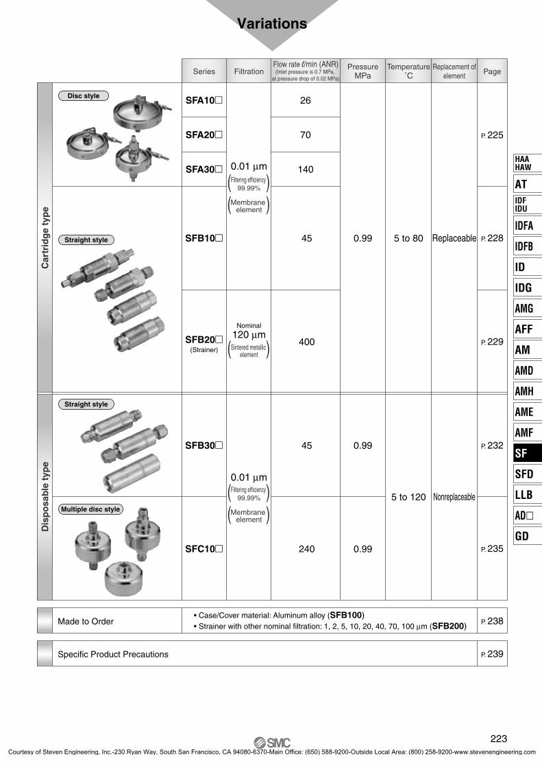
Variations
Series FiltrationTemperature
˚CPressure
MPa PageReplacement of
element
Flow rate l/min (ANR)(Inlet pressure is 0.7 MPa,
at pressure drop of 0.02 MPa)
0.01 μm
120 μm
0.01 μm
Car
trid
ge
typ
eD
isp
osa
ble
typ
e
Disc style
Straight style
Straight style
Multiple disc style
• Case/Cover material: Aluminum alloy (SFB100)• Strainer with other nominal filtration: 1, 2, 5, 10, 20, 40, 70, 100 μm (SFB200) Made to Order
Specific Product Precautions
223
AT
IDFA
IDFB
ID
IDG
AMG
AFF
AM
AMD
AMH
AME
AMF
SF
SFD
LLB
AD�
GD
HAAHAW
IDFIDU
P0221-P0284-E.qxd 08.11.6 1:57 PM Page 223
Courtesy of Steven Engineering, Inc.-230 Ryan Way, South San Francisco, CA 94080-6370-Main Office: (650) 588-9200-Outside Local Area: (800) 258-9200-www.stevenengineering.com

0 0.2 0.4
1000
100
10
10.6 10.8
0 0.2 0.4
1000
100
10
10.6 10.8
Model Selection
Determine the model by using the following procedures involving the inlet pressure and the maximum flow rate. Example) Inlet pressure: 0.6 MPa
Maximum flow rate: 200 l/min (ANR)1. Determine intersection A for the inlet pressure and the maximum flow rate by using the maximum flow rate
graph.2. If the obtained intersection A is above the maximum flow rate line, SFC10� is selected.
Note) Please be sure to select a model with a maximum flow rate line which is above the obtained intersection A.If the obtained intersection A is below the maximum flow rate line, overflow will occur. This will cause a nonconformance in which the specification will not be satisfied.
Maximum Flow Rate Lines
Max
imum
flow
rat
e l
/min
(A
NR
)
Inlet pressure MPa
Clean Gas Filter
Max
imum
flow
rat
e l
/min
(A
NR
)
Inlet pressure MPa
Clean Gas Strainer
SFB20�
SFC10�SFA30�
SFA20�
SFB10�30�
SFA10�
A
224
P0221-P0284-E.qxd 08.11.6 1:57 PM Page 224
Courtesy of Steven Engineering, Inc.-230 Ryan Way, South San Francisco, CA 94080-6370-Main Office: (650) 588-9200-Outside Local Area: (800) 258-9200-www.stevenengineering.com

Precision filtration for general gases used in the electronic industry, etc.Compressed air, Nitrogen, etc.
PTFE membrane element is made into a cartridge. (Filtration 0.01 µm (Filtering efficiency 99.99%))Made into a cartridge by polyester holder and fluorine rubber (FKM) gasket.
All products are tested at the time of shipment.Purification testAirtight test
Elements are replaceable.
Model
ED001S-X10V
ED101S-X10V
ED201S-X10V
ED001S-X10V
ED101S-X10V
ED201S-X10V
ED001S-X10V
ED101S-X10V
ED201S-X10V
0.34
0.44
0.66
0.38
0.49
0.70
0.42
0.53
0.75
Rc 1/4 (Female thread)
NPT 1/4 (Female thread)
Rc 1/4 (Female thread)
NPT 1/4 (Female thread)
Rc 1/4 (Female thread)
NPT 1/ 4 (Female thread)
26
70
140
26
70
140
26
70
140
13.85
33.18
56.75
13.85
33.18
56.75
13.85
33.18
56.75
TSJ 1/4Tube Swage
Joint
UOJ 1/4Union
O-ring Joint
SFA100-02SFA101-02SFA200-02SFA201-02SFA300-02SFA301-02SFA102-02SFA202-02SFA302-02SFA103-02SFA203-02SFA303-02
SFA302
SFA200
SFA103
Note 1) Inlet pressure 0.7 MPa, at pressure drop 0.02 MPaNote 2) Element part numbers include numbers 3 to 7 in the construction figure. (Refer to page 226.)
SFA 10 02
Model sizeSymbol Rated flow rare l/min(ANR)
102030
Up to 26Up to 70
Up to 140
ConnectionSymbol Connection (IN, OUT)
0123
RcNPTTSJUOJ
Port sizeRc, NPT, TSJ, UOJ 1/402
Symbol
Clean gas filterCartridge type
(Disc style)
0
How to order
Port size
Model Rated flow rate l/min (ANR) Note 1) Element part no. Note 2) Mass kgConnection Filtration area cm2
225
Series SFA100/200/300RoHS
Clean Gas Filter:Cartridge Type/Disc Style
AT
IDFA
IDFB
ID
IDG
AMG
AFF
AM
AMD
AMH
AME
AMF
SF
SFD
LLB
AD�
GD
HAAHAW
IDFIDU
RoHS-SF.qxd 10.7.26 5:59 PM Page 1
Courtesy of Steven Engineering, Inc.-230 Ryan Way, South San Francisco, CA 94080-6370-Main Office: (650) 588-9200-Outside Local Area: (800) 258-9200-www.stevenengineering.com

Specifications
Operating fluid
Operating pressure Note 1)
Operating temperature
Element proof differential pressure
Element reverse differential pressure
Filtration Note 2)
Purification in the outlet side
Main material
Packaging
Case
Filter medium
Seal
Air, Nitrogen
Max. 0.99 MPa, Vacuum 1.3 x 10⁻⁶ kPa
5 to 80°CMax. 0.1 MPa
Max. 0.05 MPa
0.01 μm (Filtering efficiency 99.99%)
Particle with 0.1 μm or larger 0 pcs/6 l
Stainless steel 316 (Interior/Exterior: Electrolytic polishing)
PTFE membrane
Fluororubber (FKM)
Antistatic sealed double package
Note 1) The maximum operating pressure is 0.99 MPa since this product does not conform to the High Pressure Gas Safety Law.Note 2) Based on SMC’s measuring conditions. (Refer to Technical Data SM-86-009.)
Construction
q
t
ur
y
e
w
IN
1
2
3
4
5
6
7
DescriptionNo. Material
Case
V-clamp
Holder 1
Holder 2
Filter medium
Seal
V-seal
Stainless steel 316
Stainless steel 304
Polyester
PTFE
FKM
Note
Electrolytic polishing (Interior/Exterior)
—
Cartridge element
226
Series SFA100/200/300
P0221-P0284-E.qxd 08.11.6 1:57 PM Page 226
Courtesy of Steven Engineering, Inc.-230 Ryan Way, South San Francisco, CA 94080-6370-Main Office: (650) 588-9200-Outside Local Area: (800) 258-9200-www.stevenengineering.com

1 10 100
0.1
0.01
0.001
0.00011000
1 10 100
0.1
0.01
0.001
0.00011000
1 10 100
0.1
0.01
0.001
0.0001
Pre
ssur
e dr
op
MP
a
Flow rate l/min (ANR)
SFA20�
Max. flow rate line
0.3 MPa
0.1 MPa
0.7 MPa
0.5 MPa
1000
Inlet pressure
Flow Characteristics Fluid: Compressed air Inlet temperature: 20°C
SFA10�
Dimensions
SFA100/101, SFA200/201, SFA300/301
Pre
ssur
e dr
op
MP
a
Flow rate l/min (ANR)
Max. flow rate line
0.3 MPa
0.1 MPa
0.7 MPa
0.5 MPa
Inlet pressure
IN
2 x Rc 1/4, NPT 1/4
A
øB
SFA100-02SFA101-02SFA200-02SFA201-02SFA300-02SFA301-02
46
51
59
76
96
120
A øBModel ConnectionRc 1/4
NPT 1/4Rc 1/4
NPT 1/4Rc 1/4
NPT 1/4
SFA102, SFA202, SFA302
IN
2 x TSJ 1/4
AøB
SFA102-02SFA202-02SFA302-02
89 93101
76 96120
A øBModel Connection
TSJ 1/4Tube
SwageJoint
SFA103-02SFA203-02SFA303-02
117122130
76 96120
A øBModel Connection
UOJ 1/4UnionO-ringJoint
SFA103, SFA203, SFA303
IN
7
2 x UOJ 1/4
A
øB
ø9.
5ø
6.5
Pre
ssur
e dr
op
MP
a
Flow rate l/min (ANR)
SFA30�
Max. flow rate line
0.3 MPa
0.1 MPa
0.7 MPa
0.5 MPa
Inlet pressure
227
Series SFA100/200/300Clean Gas Filter:Cartridge Type/Disc Style
AT
IDFA
IDFB
ID
IDG
AMG
AFF
AM
AMD
AMH
AME
AMF
SF
SFD
LLB
AD�
GD
HAAHAW
IDFIDU
P0221-P0284-E.qxd 08.11.6 1:57 PM Page 227
Courtesy of Steven Engineering, Inc.-230 Ryan Way, South San Francisco, CA 94080-6370-Main Office: (650) 588-9200-Outside Local Area: (800) 258-9200-www.stevenengineering.com

SFB102-02
SFB103-02
SFB101-02
Specifications
Note 1) The maximum operating pressure is 0.99 MPa since this product does not conform to the High Pressure Gas Safety Law.Note 2) Based on SMC’s measuring conditions. (Refer to Technical Data SM-86-009.)
Operating fluid
Operating pressure Note1)
Operating temperature
Element proof differential pressure
Element reverse differential pressure
Filtration Note2)
Purification in the outlet side
Main material
Packaging
Case/Cover
Filter medium
Seal
Air, Nitrogen
Max. 0.99 MPa, Vacuum 1.3 x 10⁻⁶ kPa
5 to 80°CMax. 0.5 MPa
Max. 0.07 MPa
0.01 µm (Filtering efficiency 99.99%)
Particle with 0.1 µm or larger 0 pcs/6 l
Stainless steel 316 (Interior/Exterior: Electrolytic polishing)
PTFE membrane
Fluororubber (FKM)
Antistatic sealed double package
Model
Model Element part no. Mass kg
ED301S-X10V(Including O-rings)
0.15
0.16
0.19
0.16
Connection
Rc 1/4 (Female thread)
NPT 1/4 (Female thread)
TSJ 1/4
UOJ 1/4
M5 (Female thread)
Rated flow rate l/min (ANR) Note)
45
Filtration area cm2
10
SFB100-02SFB101-02SFB102-02SFB103-02SFB104-M5Note) Inlet pressure 0.7 MPa, at pressure drop 0.02 MPa
SFB 02
ConnectionSymbol Connection (IN, OUT)
01234
RcNPTTSJUOJ
M5 (Female thread)
Port sizeRc, NPT, TSJ, UOJ
Female thread1/4M5
02M5
Symbol
Clean gas filter(Straight style)
10 0
Model typeSymbol Type
10 Cartridge type
Description—
Aluminum case (Refer to page 238.)
X8
SymbolNil
Made to Order
Port size
How to orderPrecision filtration for general gases used in the electronic industry, etc.Compressed air, Nitrogen, etc.
PTFE membrane element is made into a cartridge. (Filtration 0.01 µm (Filtering efficiency 99.99%))Made into a cartridge by polyester holder and fluorine rubber (FKM) gasket.
All products are tested at the time of shipment.Purification testAirtight test
Elements are replaceable.
Bracket is included as a standard.
228
Series SFB100RoHS
Clean Gas Filter:Cartridge Type/Straight Style
RoHS-SF.qxd 10.7.26 5:59 PM Page 2
Courtesy of Steven Engineering, Inc.-230 Ryan Way, South San Francisco, CA 94080-6370-Main Office: (650) 588-9200-Outside Local Area: (800) 258-9200-www.stevenengineering.com

Model
Model Element part no. Mass kg
ES001S-120V(Including O-rings)
0.16
0.17
0.20
Connection
Rc 1/4 (Female thread)
NPT 1/4 (Female thread)
TSJ 1/4
UOJ 1/4
Rated flow rate l/min (ANR) Note)
400
Filtration area cm2
10
SFB200-02SFB201-02SFB202-02SFB203-02
Note) Inlet pressure 0.7 MPa, at pressure drop 0.02 MPa
Specifications
Operating fluid
Operating pressure
Operating temperature Note)
Element proof differential pressure
Element reverse differential pressure
Nominal filtration
Main material
Packaging
Case/Cover
Seal
Filter medium
Air, Nitrogen
Max. 0.99 MPa, Vacuum 1.3 x 10⁻⁶ kPa
5 to 80°CMax. 1.0 MPa
Max. 1.0 MPa
120 μm
Stainless steel 316 (Interior/Exterior: Electrolytic polishing)
Fluororubber (FKM)
Stainless steel 316 sintered metal
Antistatic sealed double package
SFB 20 02
Model typeSymbol Type
20 Cartridge type (Strainer)
ConnectionSymbol Connection (IN, OUT)
0123
RcNPTTSJUOJ
Port sizeRc, NPT, TSJ, UOJ 1/402
Symbol
Clean gas strainer(Straight style)
0
Description—
Optional filtration(Refer to page 238.)
Nil
S001VX3
SymbolMade to Order
Port size
Series SFB200Clean Gas Strainer:Cartridge Type/Straight Style
How to orderCartridge made of stainless steel 316 sintered metallic element (Nominal filtration: 120 μm)Clean gas strainers made of an element (120 μm, stainless steel 316 sintered metal) to protect regulators and vacuum regulators are also available.
229
AT
IDFA
IDFB
ID
IDG
AMG
AFF
AM
AMD
AMH
AME
AMF
SF
SFD
LLB
AD�
GD
HAAHAW
IDFIDU
P0221-P0284-E.qxd 08.11.6 1:57 PM Page 229
Courtesy of Steven Engineering, Inc.-230 Ryan Way, South San Francisco, CA 94080-6370-Main Office: (650) 588-9200-Outside Local Area: (800) 258-9200-www.stevenengineering.com

q e t r w
0.1 1 10
0.1
0.01
0.001
0.0001100
0.1 1 10
0.1
0.01
0.001
0.0001100
10 100
0.1
0.01
0.001
0.00011000
IN
y
Construction Flow Characteristics Fluid: Compressed air Inlet temperature: 20°C
SFB104-M5
1
2
3
4
5
6
DescriptionNo. Material
Case
Cover
Element
O-ring
Hexagon socket head screw
Bracket
Clean gas filter
Clean gas strainer
Stainless steel 316
PTFE membrane
Stainless steel 316 sintered metal
FKM
Stainless steel 304
Note
Electrolytic polishing(Interior/Exterior)
For SFB10�For SFB20�
—
M3
—
Pre
ssur
e dr
op
MP
aFlow rate l/min (ANR)
Max. flow rate line
0.3 MPa
0.1 MPa
0.7 MPa
0.5 MPa
Inlet pressure
Pre
ssur
e dr
op
MP
a
Flow rate l/min (ANR)
SFB10�-02
0.3 MPa
0.1 MPa0.7 MPa
Max. flow rate line
0.5 MPa
Inlet pressure
Pre
ssur
e dr
op
MP
a
Flow rate l/min (ANR)
SFB20�-02
0.5 MPa
0.3 MPa
0.1 MPa
Max. flow rate line
0.7 MPa
Inlet pressure
230
Series SFB100/200
P0221-P0284-E.qxd 08.11.6 1:57 PM Page 230
Courtesy of Steven Engineering, Inc.-230 Ryan Way, South San Francisco, CA 94080-6370-Main Office: (650) 588-9200-Outside Local Area: (800) 258-9200-www.stevenengineering.com

Dimensions
SFB100/200: Rc 1/4SFB101/201: NPT 1/4SFB104: M5
IN
2 x M5, Rc 1/4, NPT 1/4
66
Bracket
ø24 40 50
2 x ø4.5
SFB100-02, 200-02SFB101-02, 201-02SFB104-M5
Model ConnectionRc 1/4
NPT 1/4M5
SFB102-02, SFB202-02: TSJ 1/4 (Tube Swage Joint)
IN
2 x TSJ 1/4
87
24 40 50
2 x ø4.5Bracket
Wid
th a
cros
s fla
ts
SFB103-02, SFB203-02: UOJ 1/4 (Union O-ring Joint)
24 40 50
2 x ø4.5 Bracket
IN
2 x UOJ 1/4
112
7
ø9.5
ø6.5
Wid
th a
cros
s fla
ts
231
Series SFB100/200Clean Gas Filter/Clean Gas Strainer:Cartridge Type/Straight Style
AT
IDFA
IDFB
ID
IDG
AMG
AFF
AM
AMD
AMH
AME
AMF
SF
SFD
LLB
AD�
GD
HAAHAW
IDFIDU
P0221-P0284-E.qxd 08.11.6 1:57 PM Page 231
Courtesy of Steven Engineering, Inc.-230 Ryan Way, South San Francisco, CA 94080-6370-Main Office: (650) 588-9200-Outside Local Area: (800) 258-9200-www.stevenengineering.com

Precision filtration for gases used in the semiconductor processCompressed air, Nitrogen, etc.
PTFE membrane with high reliability
Filtration 0.01 μm (Filtering effi-ciency 99.99%)
All products are tested at the time of shipment.Purification testHelium leak test Pressure holding test
Bracket is included as a standard.
Model
Model Mass kg
0.14
0.15
0.14
0.15
Connection
Rc 1/4 (Female thread)
TSJ 1/4
URJ 1/4
URJ 1/4
Rated flow rate l/min (ANR) Note)
45
Filtration area cm2
10
SFB300-02
SFB302-02
SFB305-02
SFB315-02Note) Inlet pressure 0.7 MPa, at pressure drop 0.02 MPa
SFB 30 02
Model typeSymbol Type
30
31
Disposable type(Narrow size)
Disposable type(Long size)
ConnectionSymbol Connection (IN, OUT)
025
RcTSJURJ
Port sizeRc, NPT, TSJ, UOJ 1/402
Symbol
Clean gas filter(Straight style)
0
* SFB31: Only 5 is selectable.
Port size
How to order
232
Series SFB300Clean Gas Filter:Disposable Type/Straight Style
P0221-P0284-E.qxd 08.11.6 1:57 PM Page 232
Courtesy of Steven Engineering, Inc.-230 Ryan Way, South San Francisco, CA 94080-6370-Main Office: (650) 588-9200-Outside Local Area: (800) 258-9200-www.stevenengineering.com

Construction
1
2
3
4
DescriptionNo. Material
Case
Cover
Element
Bracket
Stainless steel 316
PTFE membrane
Stainless steel 316 sintered metal
Note
Electrolytic polishing(Interior/Exterior)
Specifications
Operating fluid
Operating pressure Note 1)
Operating temperature
Element proof differential pressure
Element reverse differential pressure
Filtration Note 2)
Purification in the outlet side
Helium leak volume
Main material
Case/Cover
Filter medium
O-ring
Air, Nitrogen
Max. 0.99 MPa, Vacuum 1.3 x 10⁻⁶ kPa
5 to 120°C
Max. 0.5 MPa
Max. 0.07 MPa
0.01 μm (Filtering efficiency 99.99%)
Particle with 0.1 μm or larger 0 pcs/6 l
4.0 x 10⁻⁹ Pa·m3/sec or less
Stainless steel 316 (Interior/Exterior: Electrolytic polishing)
PTFE membrane
Stainless steel 304
q e r w
IN
Note 1) The maximum operating pressure is 0.99 MPa since this product does not conform to the High Pressure Gas Safety Law.Note 2) Based on SMC’s measuring conditions. (Refer to Technical Data SM-86-009.)
233
Series SFB300Clean Gas Filter:Disposable Type/Straight Style
AT
IDFA
IDFB
ID
IDG
AMG
AFF
AM
AMD
AMH
AME
AMF
SF
SFD
LLB
AD�
GD
HAAHAW
IDFIDU
P0221-P0284-E.qxd 08.11.6 1:57 PM Page 233
Courtesy of Steven Engineering, Inc.-230 Ryan Way, South San Francisco, CA 94080-6370-Main Office: (650) 588-9200-Outside Local Area: (800) 258-9200-www.stevenengineering.com

0.1 1 10
0.1
0.01
0.001
0.0001100
SFB305-02SFB315-02
Model A7984
Flow Characteristics Fluid: Compressed air Inlet temperature: 20°C
SFB30�-02
Dimensions
SFB300-02: Rc 1/4
SFB302-02: TSJ 1/4 (Tube Swage Joint)
Pre
ssur
e dr
op
MP
a
Flow rate l/min (ANR)
SFB305-02, SFB315-02: URJ 1/4 (Union Ring Joint)
Max. flow rate line
0.3 MPa
0.1 MPa
0.7 MPa
0.5 MPa
Inlet pressure
IN
2 x Rc 1/4
Bracket
13
65
ø21
.5
2 x ø4.5(Mounting hole)
5040
19
122.5
IN
2 x 1/4 TSJ
Bracket
13
69
ø21
.5
2 x ø4.5(Mounting hole)
5040
19
1
22.5
IN
2 x 1/4 URJ
Bracket
13
A
ø21
.5
2 x ø4.5(Mounting hole)
5040
19
122.5
234
Series SFB300
P0221-P0284-E.qxd 08.11.6 1:57 PM Page 234
Courtesy of Steven Engineering, Inc.-230 Ryan Way, South San Francisco, CA 94080-6370-Main Office: (650) 588-9200-Outside Local Area: (800) 258-9200-www.stevenengineering.com

Precision filtration for gases used in the semiconductor processCompressed air, Nitrogen, etc.
PTFE membrane with high reliability
Filtration 0.01 µm (Filtering effi-ciency 99.99%)
All products are tested at the time of shipment.Purification testHelium leak test Pressure holding test
Model
Model Mass kg
0.35
0.36
0.40
0.41
0.44
0.49
Connection
Rc 1/4 (Female thread)
Rc 3/8 (Female thread)
TSJ 1/4
TSJ 3/8
URJ 1/4
URJ 3/8
Rated flow rate l/min (ANR) Note)
240
Filtration area cm2
300
SFC100-02
SFC100-03
SFC102-02
SFC102-03
SFC105-02
SFC105-03Note) Inlet pressure 0.7 MPa, at pressure drop 0.02 MPa
SFC 0210
Model typeSymbol Rated flow rare l/min (ANR)
10 Up to 240
ConnectionSymbol Connection (IN, OUT)
025
RcTSJURJ
Port sizeRc, TSJ, URJRc, TSJ, URJ
1/43/8
0203
Symbol
Clean gas filterDisposable type
(Multiple style)
0Port size
How to order
235
Clean Gas Filter:Disposable Type/Multiple Disc Style
Series SFC100RoHS
AT
IDFA
IDFB
ID
IDG
AMG
AFF
AM
AMD
AMH
AME
AMF
SF
SFD
LLB
AD�
GD
HAAHAW
IDFIDU
RoHS-SF.qxd 10.7.26 5:59 PM Page 3
Courtesy of Steven Engineering, Inc.-230 Ryan Way, South San Francisco, CA 94080-6370-Main Office: (650) 588-9200-Outside Local Area: (800) 258-9200-www.stevenengineering.com
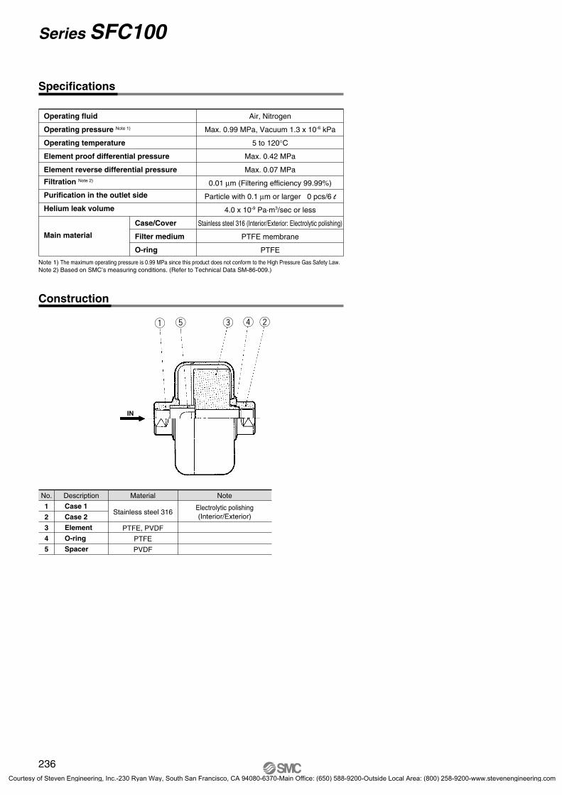
q t e r w
IN
Specifications
Operating fluid
Operating pressure Note 1)
Operating temperature
Element proof differential pressure
Element reverse differential pressure
Filtration Note 2)
Purification in the outlet side
Helium leak volume
Main material
Case/Cover
Filter medium
O-ring
Air, Nitrogen
Max. 0.99 MPa, Vacuum 1.3 x 10⁻⁶ kPa
5 to 120°C
Max. 0.42 MPa
Max. 0.07 MPa
0.01 μm (Filtering efficiency 99.99%)
Particle with 0.1 μm or larger 0 pcs/6 l
4.0 x 10⁻⁹ Pa·m3/sec or less
Stainless steel 316 (Interior/Exterior: Electrolytic polishing)
PTFE membrane
PTFE
Construction
1
2
3
4
5
DescriptionNo. Material
Case 1
Case 2
Element
O-ring
Spacer
Stainless steel 316
PTFE, PVDF
PTFE
PVDF
Note
Electrolytic polishing(Interior/Exterior)
Note 1) The maximum operating pressure is 0.99 MPa since this product does not conform to the High Pressure Gas Safety Law.Note 2) Based on SMC’s measuring conditions. (Refer to Technical Data SM-86-009.)
236
Series SFC100
P0221-P0284-E.qxd 08.11.6 1:57 PM Page 236
Courtesy of Steven Engineering, Inc.-230 Ryan Way, South San Francisco, CA 94080-6370-Main Office: (650) 588-9200-Outside Local Area: (800) 258-9200-www.stevenengineering.com

1 10 100
0.1
0.01
0.001
0.00011000
SFC100-02SFC100-03
Model ARc 1/4Rc 3/8
SFC102-02SFC102-03
Model ATSJ 1/4TSJ 3/8
SFC105-02SFC105-03
Model AURJ 1/4URJ 3/8
SFC102-02: TSJ 1/4 (Tube Swage Joint)SFC102-03: TSJ 3/8 (Tube Swage Joint)
SFC105-02: URJ 1/4 (Union Ring Joint)SFC105-03: URJ 3/8 (Union Ring Joint)
B22 26.5
C1922
Flow Characteristics Fluid: Compressed air Inlet temperature: 20°C
SFC10�
Dimensions
SFC100-02: Rc 1/4SFC100-03: Rc 3/8
Pre
ssur
e dr
op
MP
a
Flow rate l/min (ANR)
Max. flow rate line0.3 MPa
0.1 MPa
0.7 MPa
0.5 MPa
Inlet pressureIN
2 x A
68
ø76
ø22
19Widthacrossflats
IN
2 x A Front ferrule
Rear ferrule
Nut
98
ø76
ø22
19Widthacrossflats
IN
2 x A
ø76 øB
CWidthacrossflats
127
237
Series SFC100Clean Gas Filter:Disposable Type/Multiple Disc Style
AT
IDFA
IDFB
ID
IDG
AMG
AFF
AM
AMD
AMH
AME
AMF
SF
SFD
LLB
AD�
GD
HAAHAW
IDFIDU
P0221-P0284-E.qxd 08.11.6 1:57 PM Page 237
Courtesy of Steven Engineering, Inc.-230 Ryan Way, South San Francisco, CA 94080-6370-Main Office: (650) 588-9200-Outside Local Area: (800) 258-9200-www.stevenengineering.com

002
Case/Cover material: Aluminum alloy
Part No.: SFB100-02X8
Part No.: SFB200-02-S VX3Specifications
Operating fluid
Operating pressure
Max. operating temperature
Element proof differential pressure
Element reverse differential pressure
Filtration Note)
Connection
Filtration area
Element part no.
Mass
Main material
Case/Cover
Seal
Element
Air
Max. 0.99 MPa
80°C
Max. 0.5 MPa
Max. 0.07 MPa
0.01 μm (Filtering efficiency 99.99%)
Rc 1/4
10 cm2
ED301S-X10V
0.06 kg
A2017 (Clear anodized)
Fluororubber (FKM)
PTFE membrane
Strainer with other filtration (1,2,5,10,20,40,70,100 μm)
Nominal filtrationNominal filtration μm
125
10204070
100
Symbol001002005010020040070100
Dimensions are identical to the standard models. For details, refer to page 231.Note) Based on SMC’s measuring conditions. (Refer to Technical Data SM-86-009.)
Specifications and dimensions are identical to the standard models. For details, refer to page 231.
The filtration other than the standard filtration accuracy, 120 μm, is available with the clean gas strainer.
Element Part No.
Nominal filtration (μm) NotePart no.
O-ring
1
2
5
10
20
40
70
100
ES001S-001VX0
ES001S-002VX0
ES001S-005VX0
ES001S-010VX0
ES001S-020VX0
ES001S-040VX0
ES001S-070VX0
ES001S-100VX0
Series SFMade to Order Specifications:Contact us for detailed dimensions, specifications and delivery.
238
P0221-P0284-E.qxd 08.11.6 1:57 PM Page 238
Courtesy of Steven Engineering, Inc.-230 Ryan Way, South San Francisco, CA 94080-6370-Main Office: (650) 588-9200-Outside Local Area: (800) 258-9200-www.stevenengineering.com

AT
IDFA
IDFB
ID
IDG
AMG
AFF
AM
AMD
AMH
AME
AMF
SF
SFD
LLB
AD�
GD
HAAHAW
IDFIDU
Warning
Warning
Operating Environment
Warning
Caution on Design
Caution
Maintenance
Warning
Maintenance
Warning
Series SF �Specific Product Precautions 1Be sure to read before handling. Refer to front matters 42 and 43 for Safety Instructions and pages 6 to 8 for Air Preparation Equipment Precautions.
Selection
1. Confirm the specifications.This product is designed for only general gases such as compressed air or Nitrogen.Do not use this product with special gases, pressure or temperature beyond the specifications. Otherwise, they could cause damage to the product.(Refer to the specifications.)
Mounting
1. Instruction manualMount the product after reading and understanding the instruction manual. Keep it in a location where it can easily be found.
2. Provide enough space for maintenance.Provide space for maintenance because the IN/OUT pipings have to be removed when the elements are replaced.
3. Follow the piping instructions on the back of pages 240 and 241 when a screw is tightened.
1. Do not use the product in a place where corrosive gas, chemicals, brine, water and/or water steam are present or can splash on it.
2. Insulate the product if it is used under direct sunlight.
3. Avoid using the product in a place where vibration or impact can occur.
4. Do not use the product in the vicinity of a heat source or under radiant heat.
1. Follow the maintenance procedures in the instruction manual. If handled incorrectly equipment or device can be damaged or cause a malfunction.
2. Maintenance Product specification must be oberved, because mishandling compressed air and/or Nitrogen can cause a dangerous situation. Maintenance such as replacing elements has to be performed by a well-experienced and knowledgeable person.
3. Pre-maintenance inspectionWhen removing the product, turn off the electrical power, and be sure to shut off the supply pressure and exhaust the compressed air in the system. Proceed only after confirming that all pressure has been released to the atmosphere.
4. Post maintenance inspectionAfter installation or repair, perform an appropriate function and leakage test.
5. Modification is prohibited.Do not disassemble or modify the product.
1. If the pressure difference (pressure drop) between the inlet and the outlet exceeds 0.1 MPa, it can cause damage to the product.
2. Do not install the product in a place where it can be affected by a pulsation of over 0.1 MPa.
3. Use caution regarding the particles that may be emitted from the outlet side of a pneumatic equipment.Installation of a pneumatic equipment on the outlet side of the SF� series can deteriorate the cleanliness because a particle will be generated from the equipment. In the case of installing the pneumatic equipment in the outlet side of the SF� series, dusts can be generated from the equipment, and the degree of cleanliness can be deteriorated. The mounting position of the pneumatic equipment needs to be considered depending on the degree of cleanliness of a required operating fluid.
4. Design the system to prevent reverse pressure and reverse flow.Reverse pressure and reverse flow can damage the element.
5. Design that the piping load should not be applied on the product body.Mount a bracket for the piping and the other connecting equipment so that the piping load is not applied to the product body.
6. Generally, the following pollutant particles are contained in compressed air, although the degree of cleanliness of the compressed air is different depending on the compressor type and specification. [Pollutant particle substances contained in the compressed air]• Moisture (drainage)• Dusts and particles which are in the surrounding air• Deteriorated oil which is discharged from the compressor• Solid foreign matter such as rust and/or oil in the piping
1) The SF� series is not compatible with compressed air which contains fluids such as water and/or oil.
2) Install a dryer (IDF, IDG, ID series), mist separator (AM series), micro mist separator (AMD series), super mist separator (AME series), or odor removal filter (AMF series), etc., for the source of the air for the SF� series.
239
P0221-P0284-E.qxd 08.11.6 1:57 PM Page 239
Courtesy of Steven Engineering, Inc.-230 Ryan Way, South San Francisco, CA 94080-6370-Main Office: (650) 588-9200-Outside Local Area: (800) 258-9200-www.stevenengineering.com

Selection
Warning
Piping
Caution
Piping
Caution1. Thoroughly and carefully confirm the purpose
of use, required specifications and operating conditions (fluid, pressure, flow rate and environment) then select a model within the specifications.
2. Contact us beforehand when the product will be used in applications such as a caisson shield, and breathing and/or medical treatment that affects the human body directly or indirectly.
3. Determine the product by the maximum consumption flow rate.When using compressed air for an air blow application, calculate the maximum volume of air that will be consumed before selecting the SF� series product size. (Using a product which exceeds the maximum air flow and running excessive compressed air can cause the cleanliness of the compressed air to deteriorate and/or its element to be damaged.
4. Set the air flow capacity with an initial pressure drop of 0.02 MPa or less.If the initial pressure drop is set to be high, its service life will be shorten due to clogging.
1. Unpacking the sealed packageSince the filter is sealed in an antistatic double bag, the inner package should be unpacked in a clean atmosphere (such as a clean room).
2. Confirm that there is enough space for maintenance before installing and piping this product.
3. Apply a wrench to 2 chamfered flats on the IN side or the OUT side to prevent the housing from rotating.
4. Confirm the IN and the OUT before piping. The product should not be used with the wrong connection.
5. Wrapping of pipe tapeWhen screwing together pipes and fittings, etc., confirm that chips from the pipe threads and sealing material do not enter the piping.Also, when pipe tape is used, leave 1.5 to 2 thread ridges exposed at the end of the threads.
6. Connection1) Rc and NPT connection
Confirm that chips from the pipe threads and sealing material do not enter the piping.Also, when pipe tape is used, leave 1.5 to 2 thread ridges exposed at the end of the threads.
2) TSJ connectionThe TSJ fitting is a kind of a self-align fittings. Set it as shown in the figure.
Regarding the TSJ fittings, after tightening the nut by hand, add another 1 1/4 to 1 1/2 turns with a wrench to seal the fitting. In case the fitting is re-installed after filter replacement, first tighten the nut by hand and add another 1/4 to 1/2 turns for sealing. Use the following parts as piping and fittings. • Piping Outside diameter 1/4" = ø6.35 mm
Stainless steel pipeor
Outside diameter 3/8" = ø9.53 mm Stainless steel pipe
• Nut• Front ferrule Attached to product (2 pcs each)• Rear ferruleIn the event of replacing the body, a space (20 mm or longer) for extending the stainless steel tubes from the IN and OUT side will be required. When using similar fittings of other brands, be sure to conduct a helium leak test to confirm there is no leakage before using.
3) UOJ fittingsThe UOJ fitting is a union type fitting using a O-ring seal.Install it as illustrated below.
Weld the ground and piping when the fitting is used. At the time of welding, supply inert gas such as Nitrogen to the piping to prevent the formation of an oxide film. Also, remove the oxide film on the external surface through electrolytic polishing or acid cleaning.After tightening the nut by hand, add another 1/8 turn with a wrench to seal the fitting. Use the following parts for piping and fittings.• Piping Outside diameter 1/4" = ø6.35 mm
Stainless steel pipe• Nut• Ground Attached to product (2 pcs each)• O-ring
Outside diameter 1/4" = ø6.35 mmOutside diameter 3/8" = ø9.53 mm
Filter case Nut
Stainless steel tube
Rear ferruleFront ferrule
Outside diameter 1/4" = ø6.35 mm
Nut WeldingGroundFilter case
Stainless steel tube
O-ring
Series SF �Specific Product Precautions 2Be sure to read before handling. Refer to front matters 42 and 43 for Safety Instructions and pages 6 to 8 for Air Preparation Equipment Precautions.
240
P0221-P0284-E.qxd 08.11.6 1:57 PM Page 240
Courtesy of Steven Engineering, Inc.-230 Ryan Way, South San Francisco, CA 94080-6370-Main Office: (650) 588-9200-Outside Local Area: (800) 258-9200-www.stevenengineering.com

AT
IDFA
IDFB
ID
IDG
AMG
AFF
AM
AMD
AMH
AME
AMF
SF
SFD
LLB
AD�
GD
HAAHAW
IDFIDU
Piping
Caution
Piping
Caution
Operating Fluid
Warning
4) URJ fittings
The URJ fitting is a union type fitting using a metal gasket.Install it as illustrated below.
Weld the ground and piping when the fitting is used. At the time of welding, supply inert gas such as Nitrogen to the piping to prevent the formation of an oxide film. Also, remove the oxide film on the external surface through electrolytic polishing or acid cleaning.
After tightening the nut by hand, add another 1/8 turn with a wrench to seal the fitting. Use the following parts for piping and fittings.
<1/4">
• Nut VCR® fittings by Cajon Company
VCR female nut
(SS-4-VCR-1)
• Ground VCR® fittings by Cajon Company
VCR female ground
(SS-4-VCR-3)
• Gasket VCR® fittings by Cajon Company
VCR gasket retainer assembly
(SS-4-VCR-2-GR)
<3/8">
• Piping O.D. 3/8" = ø9.53 mm
Stainless steel pipe
• Nut VCR® fittings by Cajon Company
VCR female nut
(SS-8-VCR-1)
• Ground VCR® fittings by Cajon Company
VCR female ground
(SS-8-VCR-3)
• Gasket VCR® fittings by Cajon Company
VCR gasket retainer assembly
(SS-8-VCR-2-GR)
Be sure to conduct a helium leak test before using similar fittings from other companies.Note) VCR® is a registered trademark of Cajon Company
7. Line flushingFlush the piping line when the filter is used for the first time or has been replaced. In the event of connecting such as piping, flush (air blow) when using this product for the first time or replacing its elements in order to reduce the affect of the dust generated from the connection, etc.
Flushing the line is also required to eliminate contamination resulting from the piping line installation. Therefore, be sure to flush the line before actually running the system.
When general gases (excluding toxic, corrosive and flammable gases) are used after mounting the filter, sufficiently flush the line with a dry inert gas such as Nitrogen gas. This should be followed by a helium leak test on the fittings before actually running the product.
8. Filter replacement (or element replacement)Release the gas from the piping to reduce the internal pressure to 0.
Also, when Nitrogen gas is used, replace it with dry Nitrogen gas by purging it in advance.
Replace the filter (or cartridge element) when a differential pressure of 0.1 MPa (pressure drop) between IN and OUT is reached and/or when 1 year has elapsed.
9. Filter replacement should be performed according to the instruction manual to maintain the filter performance and safety.The instruction manual is contained in the replacement element. However, if the manual is lost, another one can be requested by inquirying to our company.
1. Do not use the clean gas filter with fluids other than inert gas such as compressed air and Nitrogen gas. Using this product with fluids other than inert gas such as compressed air and Nitrogen gas can cause damage and leaks in the seals and O-rings, depending on the operating fluid.Confirm the seal material in the specifications and the compatibility with the operating fluid.
Model Series SFA
Series SFB10, 20
Model Series SFB30
Series SFC
Nut
Welding
GroundFilter case Stainless steel
tube
Gasket
Outside diameter 1/4" = ø6.35 mmOutside diameter 3/8" = ø9.53 mm
Series SF �Specific Product Precautions 3Be sure to read before handling. Refer to front matters 42 and 43 for Safety Instructions and pages 6 to 8 for Air Preparation Equipment Precautions.
241
P0221-P0284-E.qxd 08.11.6 1:57 PM Page 241
Courtesy of Steven Engineering, Inc.-230 Ryan Way, South San Francisco, CA 94080-6370-Main Office: (650) 588-9200-Outside Local Area: (800) 258-9200-www.stevenengineering.com

Operating Environment
Caution
Maintenance
1. When the product is used for blowing, use caution to prevent the work from being damaged by entrained air from the surrounding area.When the compressed air is used for air blow, the exhausted air from the blow nozzle may have taken in airborne foreign matter (such as solid particle, fluid particle) from the surround air. The foreign matter will be sprayed on the work, and the airborne foreign matter may adhere to it.
Therefore, use caution for the surrounding environment.
1. When the element comes to the end of its life, immediately replace it with a new filter or replacement element (cartridge type).
2. Service life of element The service life of the element ends when either of the following two conditions occurs.
1) After 1 year of usage has elapsed.
2) When the pressure drop reaches 0.1 MPa even though the operating period has been less than 1 year.
3. Unpacking the sealed packageSince the filter, as well as the cartridge element (cartridge type) are sealed in an antistatic double bag, the inner package should be unpacked in a clean atmosphere (such as a clean room).
Series SF �Specific Product Precautions 4Be sure to read before handling. Refer to front matters 42 and 43 for Safety Instructions and pages 6 to 8 for Air Preparation Equipment Precautions.
242
P0221-P0284-E.qxd 08.11.6 1:57 PM Page 242
Courtesy of Steven Engineering, Inc.-230 Ryan Way, South San Francisco, CA 94080-6370-Main Office: (650) 588-9200-Outside Local Area: (800) 258-9200-www.stevenengineering.com