Embed Size (px)
Citation preview

Cary 50
Spectrophotometer
Hardware Manual
2 Cary 50 Spectrophotometer Hardware Manual
Notices
© Agilent Technologies, Inc. 1998,
1999, 2002, 2004, 2006, 2010 and 2011
No part of this manual may be
reproduced in any form or by any
means (including electronic storage
and retrieval or translation into a
foreign language) without prior
agreement and written consent from
Agilent Technologies, Inc. as governed
by United States and international
copyright laws.
Manual Part Number
8510159600
Edition
Ninth edition, March 2011
Printed in Australia
Agilent Technologies, Inc.
Warranty
The material contained in this
document is provided “as is,” and is
subject to being changed, without
notice, in future editions. Further, to
the maximum extent permitted by
applicable law, Agilent disclaims all
warranties, either express or implied,
with regard to this manual and any
information contained herein,
including but not limited to the
implied warranties of merchantability
and fitness for a particular purpose.
Agilent shall not be liable for errors
or for incidental or consequential
damages in connection with the
furnishing, use, or performance of
this document or of any information
contained herein. Should Agilent and
the user have a separate written
agreement with warranty terms
covering the material in this
document that conflict with these
terms, the warranty terms in the
separate agreement shall control.
Technology Licenses
The hardware and/or software
described in this document are
furnished under a license and may be
used or copied only in accordance
with the terms of such license.
Restricted Rights Legend
If software is for use in the
performance of a U.S. Government
prime contract or subcontract,
Software is delivered and licensed as
“Commercial computer software” as
defined in DFAR 252.227-7014 (June
1995), or as a “commercial item” as
defined in FAR 2.101(a) or as
“Restricted computer software” as
defined in FAR 52.227-19 (June 1987)
or any equivalent agency regulation or
contract clause. Use, duplication or
disclosure of Software is subject to
Agilent Technologies‟ standard
commercial license terms, and non-
DOD Departments and Agencies of the
U.S. Government will receive no
greater than Restricted Rights as
defined in FAR 52.227-19(c)(1-2) (June
1987). U.S. Government users will
receive no greater than Limited Rights
as defined in FAR 52.227-14 (June
1987) or DFAR 252.227-7015 (b)(2)
(November 1995), as applicable in any
technical data.
Safety Notices
A CAUTION notice denotes a hazard.
It calls attention to an operating
procedure, practice, or the like that, if
not correctly performed or adhered to,
could result in damage to the product
or loss of important data. Do not
proceed beyond a CAUTION notice
until the indicated conditions are fully
understood and met.
A WARNING notice denotes a
hazard. It calls attention to an
operating procedure, practice, or the
like that, if not correctly performed or
adhered to, could result in personal
injury or death. Do not proceed
beyond a WARNING notice until the
indicated conditions are fully
understood and met.
WARNING
CAUTION

Contents
Cary 50 Spectrophotometer Hardware Manual 3
Contents
1. Safety Practices and Hazards 5
Lamp module 6
Electrical hazards 6
Modules, covers and panels 6
Other precautions 7
Warning and caution messages 7
Information symbols 8
Color coding 9
CE compliance 10
2. Introduction 11
Installation requirements 11
Documentation 11
Conventions 12
Specifications 12
Environmental 13
Weights and dimensions 13
Computer power supply 13
Connections 14
3. Installation 15
Cell holder 16
Alignment 18
Other sample holders 18
Contents
4 Cary 50 Spectrophotometer Hardware Manual
Uninstalling the Cary WinUV software 19
Uninstalling the Cary 50 driver 19
4. Maintenance 21
Cleaning 22
Lamp module 22
Replacing 22
Aligning the source mirror 25
5. Troubleshooting 27
Windows XP service or driver failure 27
Access denied during installation 28
FCary service failed to start 29
No green light indicating that the Cary 50 is powered 30
Start button replaced with Connect button 30
Hard disk power supply connection 32
Absorbance is 10 and fluctuates wildly during a scan 32
Instrument performance testing 33
Wavelength calibration 35
6. Spare Parts 37

Safety Practices and Hazards
Cary 50 Spectrophotometer Hardware Manual 5
1. Safety Practices and Hazards
Lamp module 6
Electrical hazards 6
Modules, covers and panels 6
Other precautions 7
Warning and caution messages 7
Information symbols 8
Color coding 9
CE compliance 10
Your Agilent Cary 50 instrument and accessories have been carefully designed so that when used properly, you have an accurate, fast, flexible and safe analytical system.
If the equipment is used in a manner not specified by the manufacturer, the protection provided by the equipment may be impaired.
Information about safety practices appears throughout the documentation (both hard copy and online) provided with your instrument and accessories to help you safely operate the instrument and accessories. Before using the instrument or accessories, you must thoroughly read these safety practices. ALWAYS operate the instrument and accessories in accordance with these safety practices.
Safety Practices and Hazards
6 Cary 50 Spectrophotometer Hardware Manual
Lamp module
The lamp is enclosed in a self-contained module. This module contains components operating at high voltages. To avoid electric shock, NEVER disassemble the module.
When operating, the lamp module emits high-intensity light, which can cause serious damage to eyes. To avoid eye damage, never operate the lamp outside the instrument.
Electrical hazards
The Cary 50 spectrophotometer is powered by the computer controlling the instrument. Safe operation of the instrument depends on the integrity of the switching power supply of the computer. Your computer must comply with IEC 60950.
Modules, covers and panels
The ONLY modules of the Cary 50 spectrophotometer that operators and other unauthorized personnel are permitted to access are the lamp module (on the underside of the instrument) and the sample compartment. White circles indicate the screws you need to undo to remove the lamp module. ALWAYS switch off the computer before changing a lamp.
The only panel you are permitted to remove is the snap-out panel covering the lamp mirror adjustment screws on the front of the instrument.
Any other panels or covers that are retained by screws on the spectrophotometer and accessories may be opened ONLY by Agilent-trained, Agilent-qualified, or Agilent-approved customer support representatives. Consult the manuals or product labels supplied with your computer, monitor and printer to determine which parts are operator-accessible.
NOTE The safety classification is given as Safety Class III (EN 61010-1).
Safety Practices and Hazards
Cary 50 Spectrophotometer Hardware Manual 7
Other precautions
Do not block any ventilation grilles present on the computer. Consult the manuals supplied with your computer, monitor and printer for their specific ventilation requirements.
Use of the Cary 50 system and accessories may involve materials, solvents and solutions that are flammable, corrosive, toxic or otherwise hazardous.
Careless, improper, or unskilled use of such materials, solvents and solutions can create explosion hazards, fire hazards, toxicity and other hazards which can result in death, serious personal injury, and damage to equipment and property.
ALWAYS ensure that laboratory safety practices governing the use, handling and disposal of such materials are strictly observed. These safety practices should include the wearing of appropriate safety clothing and safety glasses.
Warning and caution messages
Carefully read all warnings and cautions and observe them at all times.
A Warning message is used in the text when failure to observe instructions or precautions could result in death or injury. Warnings have the following format:
WARNING
Hazard Type
Nature of the hazard, information on how to avoid the hazard, and possible
consequences if you don’t.
The triangular symbols that appear in conjunction with warnings are outlined in the next section.

Safety Practices and Hazards
8 Cary 50 Spectrophotometer Hardware Manual
A Caution message is used when failure to observe instructions could result in damage to equipment (Agilent-supplied and/or other associated equipment). Cautions have the following format:
CAUTION Caution information appears here.
Information symbols
The following triangular symbols appear in conjunction with warnings on the spectrometer and associated documentation. The hazard they depict is shown below each symbol:
Broken glass
Corrosive liquid
Electrical shock
Eye hazard
Fire hazard
Heavy weight
(danger to feet)
Heavy weight
(danger to hands)
Hot surface
Noxious gas
The following symbol may be used on warning labels attached to the instrument. When you see this symbol, refer to the relevant operation or service manual for the correct procedure referred to by that warning label.
Safety Practices and Hazards
Cary 50 Spectrophotometer Hardware Manual 9
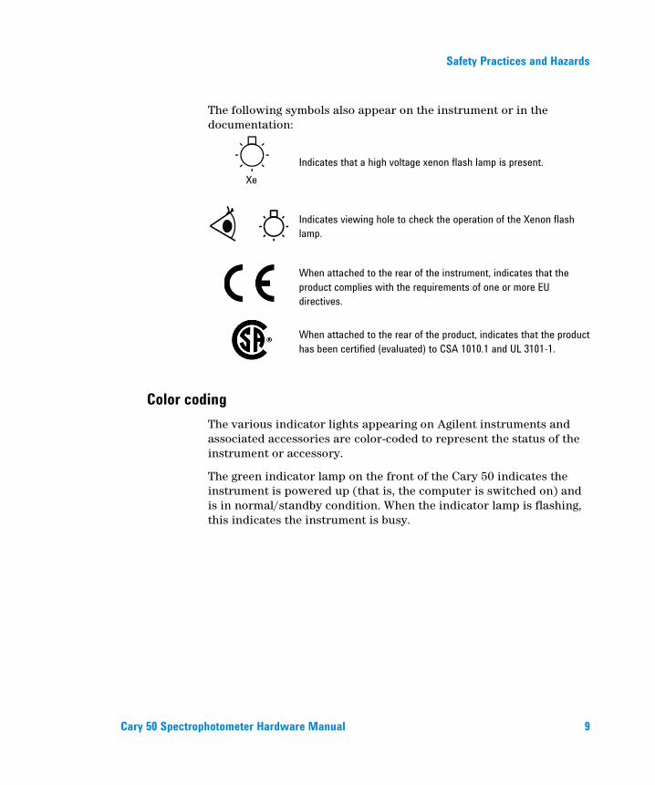
The following symbols also appear on the instrument or in the documentation:
Xe
Indicates that a high voltage xenon flash lamp is present.
Indicates viewing hole to check the operation of the Xenon flash
lamp.
When attached to the rear of the instrument, indicates that the
product complies with the requirements of one or more EU
directives.
When attached to the rear of the product, indicates that the product
has been certified (evaluated) to CSA 1010.1 and UL 3101-1.
Color coding
The various indicator lights appearing on Agilent instruments and associated accessories are color-coded to represent the status of the instrument or accessory.
The green indicator lamp on the front of the Cary 50 indicates the instrument is powered up (that is, the computer is switched on) and is in normal/standby condition. When the indicator lamp is flashing, this indicates the instrument is busy.

Safety Practices and Hazards
10 Cary 50 Spectrophotometer Hardware Manual
CE compliance
Agilent Cary 50 instruments have been designed to comply with the requirements of the Electromagnetic Compatibility (EMC) Directive and the Low Voltage (electrical safety) Directive (commonly referred to as the LVD) of the European Union. Agilent has confirmed that each product complies with the relevant directives by testing a prototype against the prescribed EN (European Norm) standards.
Proof that a product complies with the directives is indicated by:
The CE marking appearing on the rear of the product.
The documentation package that accompanies the product, containing a copy of the Declaration of Conformity. This declaration is the legal declaration by Agilent that the product complies with the directives and also shows the EN standards to which the product was tested to demonstrate compliance.
Introduction
Cary 50 Spectrophotometer Hardware Manual 11
2. Introduction
Installation requirements 11
Documentation 11
Specifications 12
Installation requirements
Before receiving your instrument, you will have been provided with a Cary 50 PReinstallation Manual (publication number 8510161800), which describes the environmental and operating requirements of the Cary 50 spectrophotometer. You must prepare your laboratory according to these instructions before the Cary 50 can be installed. You should keep the pReinstallation manual for future reference. If you have misplaced your copy, you can obtain a free replacement from your local Agilent office. Alternatively, download a PDF from the Agilent Web site, www.agilent.com
Documentation
You have been provided with the following documentation to help you set up and operate your Agilent Cary 50 spectrophotometer:
Installation guides (one for each supported operating system), with information on unpacking the instrument, installing the interface card in the computer and setting up the system.
This operation manual, with safety practices and hazards information, instructions for installing and maintaining the components of the Cary 50, and troubleshooting information.

Introduction
12 Cary 50 Spectrophotometer Hardware Manual
Cary WinUV Software Manual (publication number 8510162500), with instructions for installing the Cary WinUV software, an overview of the software and software-related troubleshooting information.
Extensive online Help (provided with the Cary WinUV software) containing context-sensitive Help, step-by-step instructions for frequently performed analyses and instructions for using any accessories you ordered.
Conventions
The following conventions have been used throughout the documentation:
Menus, menu items, buttons and check boxes have been typed in bold. For example, ‘click OK’ and ‘From the Edit menu, choose Copy’.
ALL CAPITALS indicate keyboard commands. For example, ‘Press ENTER’ and ‘Press SHIFT+F3’.
NOTE Throughout this manual, UV Dissolution and UV Fiber Optic Dissolution users
should replace „Cary WinUV Software‟ with „UV Dissolution Software‟ or „UV
Fiber Optic Dissolution Software‟ respectively.
Specifications
The instrument is suitable for indoor use only and is classified Pollution degree 2 and Installation Category II (EN 61010-1).
Introduction
Cary 50 Spectrophotometer Hardware Manual 13
Environmental
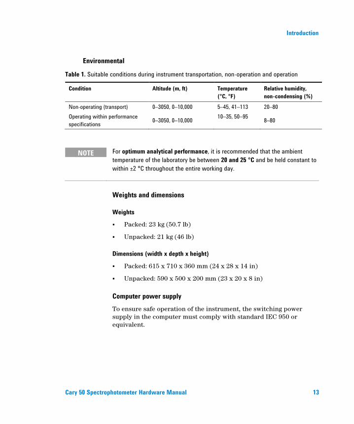
Table 1. Suitable conditions during instrument transportation, non-operation and operation
Condition Altitude (m, ft) Temperature
(°C, °F)
Relative humidity,
non-condensing (%)
Non-operating (transport) 0–3050, 0–10,000 5–45, 41–113 20–80
Operating within performance
specifications 0–3050, 0–10,000
10–35, 50–95 8–80
NOTE For optimum analytical performance, it is recommended that the ambient
temperature of the laboratory be between 20 and 25 °C and be held constant to
within ±2 °C throughout the entire working day.
Weights and dimensions
Weights
Packed: 23 kg (50.7 lb)
Unpacked: 21 kg (46 lb)
Dimensions (width x depth x height)
Packed: 615 x 710 x 360 mm (24 x 28 x 14 in)
Unpacked: 590 x 500 x 200 mm (23 x 20 x 8 in)
Computer power supply
To ensure safe operation of the instrument, the switching power supply in the computer must comply with standard IEC 950 or equivalent.
Introduction
14 Cary 50 Spectrophotometer Hardware Manual
The power requirements of the Cary 50 must be met by the computer power supply and the following capacity (in addition to what is required by the computer itself) is required:
+5 V DC <1 A
+12 V DC <1.5 A
-12 V DC <0.25 A
a total of 26 W for the instrument
Allowance must also be made for external accessories powered by +12 V DC.
Operating motor-driven accessories will increase the +12 V current by a further 2 A (a maximum of 24 W for accessories).
Agilent recommends a computer power supply rating of 220 W as a minimum.
Connections
3.5 mm phono jack socket in the left side of the sample compartment for accessories.
8-pin DIN connector in the left side of the sample compartment for the diode detector.
25-pin D-range connector in the right side of the sample compartment for accessories (optional).
NOTE If an external cooling air supply system is required, an air inlet duct attachment
(part number 0110595300) must be ordered with the instrument.

Installation
Cary 50 Spectrophotometer Hardware Manual 15
3. Installation
Cell holder 16
Uninstalling the Cary WinUV software 19
Uninstalling the Cary 50 driver 19
The Agilent Cary 50 spectrophotometer is designed to be completely customer-installed. Instructions for setting up the system are included in the installation guides supplied with the instrument. You should select the one appropriate for the operating system you are using on your computer.
WARNING
Heavy Weight Hazard
The Cary 50 weighs over 20 kg (44 lb). To avoid injury to personnel or damage
to equipment, always use two or more people when lifting or carrying the
instrument. NEVER attempt to lift the instrument alone.
Details for unpacking the instrument and what to do in case it has been damaged in transit are outlined in the pReinstallation manual.
Following the instructions in the Cary 50 Installation Instructions (Publication Number 8510185100) you should have:
Unpacked the spectrophotometer and placed it on the intended workbench.
Connected the computer to the power supply.
Installed the Cary WinUV software.
Installed the instrument interface card in the computer (if you supplied your own computer).
Installation
16 Cary 50 Spectrophotometer Hardware Manual
Installed the Accessory Cable kit (if ordered).
Connected the instrument to the computer.
Completed the instrument performance tests.
This chapter describes how to install the sample holders used with the Cary 50, and how to uninstall the software and driver, should you ever need to. Instructions for installing/replacing the lamp module are included in the Maintenance chapter.
Cell holder
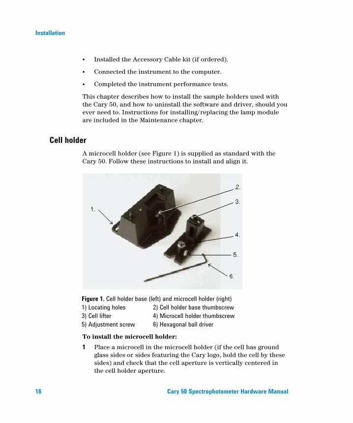
A microcell holder (see Figure 1) is supplied as standard with the Cary 50. Follow these instructions to install and align it.
Figure 1. Cell holder base (left) and microcell holder (right)
1) Locating holes 2) Cell holder base thumbscrew
3) Cell lifter 4) Microcell holder thumbscrew
5) Adjustment screw 6) Hexagonal ball driver
To install the microcell holder:
1 Place a microcell in the microcell holder (if the cell has ground glass sides or sides featuring the Cary logo, hold the cell by these sides) and check that the cell aperture is vertically centered in the cell holder aperture.
Installation
Cary 50 Spectrophotometer Hardware Manual 17
2 If the cell aperture is not at the correct height, remove the cell and adjust the grub screw in the microcell holder accordingly using the 2.5 millimeter hexagonal ball driver. Replace the cell in the microcell holder.
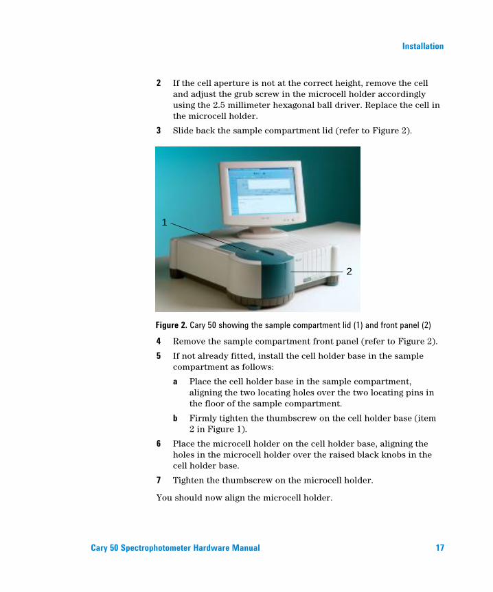
3 Slide back the sample compartment lid (refer to Figure 2).
1
2
Figure 2. Cary 50 showing the sample compartment lid (1) and front panel (2)
4 Remove the sample compartment front panel (refer to Figure 2).
5 If not already fitted, install the cell holder base in the sample compartment as follows:
a Place the cell holder base in the sample compartment, aligning the two locating holes over the two locating pins in the floor of the sample compartment.
b Firmly tighten the thumbscrew on the cell holder base (item 2 in Figure 1).
6 Place the microcell holder on the cell holder base, aligning the holes in the microcell holder over the raised black knobs in the cell holder base.
7 Tighten the thumbscrew on the microcell holder.
You should now align the microcell holder.
Installation
18 Cary 50 Spectrophotometer Hardware Manual
Alignment
To align the microcell holder:
1 Start the Align application by clicking the Windows® Start button and choosing (All) Programs, Agilent, Cary WinUV (or Agilent, UV/UV FO Dissolution) then Align.
2 Click the Cary tab.
3 Under ‘Instrument Parameters’, set the wavelength to 0 nm (white light) by selecting Zero Order.
4 Click Apply. The green power indicator on the instrument should start flashing to indicate that the instrument is active.
5 Place a cell in the microcell holder (if you have not already done so).
6 Place a small piece of white paper in the light path to the right of the cell. If the beam appears as though it will strike the cell aperture, move the paper to the left of the cell and check that the beam is passing through the cell. (If the beam does not appear as though it will pass through the cell, adjust the height of the cell as described on Page 17.)
7 Using the 2.5 millimeter hexagonal ball driver, adjust the microcell holder adjustment screw (item 5 in Figure 1) and note the intensity of the light striking the paper. Continue to adjust the adjustment screw until the beam hitting the paper appears the most intense.
NOTE You may need to dim the room lights to see the light beam.
Other sample holders
Other sample holders are available for use with the Cary 50, such as the Solid Sample Holder. Instructions for their use are included in the online Help provided with the Cary WinUV software. Refer to the Cary WinUV Software Manual (part number 8510162500) for details on using the online Help.

Installation
Cary 50 Spectrophotometer Hardware Manual 19
Uninstalling the Cary WinUV software
NOTE For Pharma software, you will need to contact your local Agilent office, as a
service call will be required to uninstall Cary WinUV Pharma software.
To uninstall the Cary WinUV Software:
1 Click the Windows Start button and choose Control Panel > Add/Remove Programs.
2 Scroll through the list on the Install/Uninstall tabbed page until you find ‘Agilent Cary WinUV’.
3 Click Add/Remove and then Yes. Follow the instructions on the screen.
4 Repeat Step 3 for the Cary WinUV Help.
Uninstalling the Cary 50 driver
To uninstall the Cary 50 driver:
1 Click the Windows Start button and choose Control Panel > System.
2 On the Hardware tab, select Device Manager, and click the plus (‘+’) icon next to ‘Other’ devices.
3 Right-click Cary 50 PCI Rev03 and then click Uninstall.
4 Restart the computer.

Installation
20 Cary 50 Spectrophotometer Hardware Manual
This page is intentionally left blank.
Maintenance
Cary 50 Spectrophotometer Hardware Manual 21
4. Maintenance
Cleaning 22
Lamp module 22
This chapter includes the Agilent Cary 50 spectrophotometer maintenance procedures that may be carried out by an operator. Any maintenance procedures not specifically mentioned in this chapter should be carried out only by Agilent-trained, Agilent-qualified or Agilent-authorized customer support representatives.
WARNING
Eye Hazard
This instrument contains an intense light source. Direct viewing of the light
source will cause eye damage. Operators and other unauthorized personnel
must NEVER remove the main cover.
NOTE This section refers only to maintenance procedures for the instrument. You
should refer to your computer and printer/plotter manuals for their maintenance
procedures, and to the Cary WinUV online Help for the maintenance procedures
for any accessories you ordered.
Maintenance
22 Cary 50 Spectrophotometer Hardware Manual
Cleaning
Any spills in the sample compartment should be immediately wiped up.
The exterior surfaces of the Cary 50 spectrophotometer should be kept clean. All cleaning should be done with a soft cloth. If necessary, this cloth can be dampened with water or a mild detergent. Do not use organic solvents or abrasive cleaning agents.
Lamp module
This section describes how to replace the lamp module and realign the light beam. Before changing the lamp module, ALWAYS disconnect the Cary 50 from the computer.
NOTE These instructions are also provided in the Cary WinUV Help, complete with a
video demonstration. Refer to the Cary WinUV Software Manual (part number
8510162500) for details on using the online Help.
Replacing
WARNING
Shock and Eye Hazards
When operating, the lamp module emits high-intensity light, which can
damage eyes. To avoid eye damage, never operate the lamp module outside
the instrument.
The lamp module contains components operating at high voltages. To avoid
electric shock, NEVER disassemble the lamp module.
Maintenance
Cary 50 Spectrophotometer Hardware Manual 23
To remove the lamp module:
1 Remove the plug from the ‘inst’ connector on the rear panel of the Cary 50.
2 Turn the Cary 50 onto its side to give access to the base.
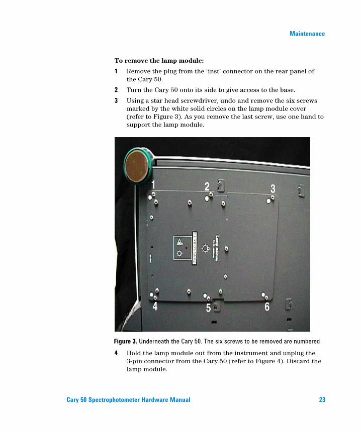
3 Using a star head screwdriver, undo and remove the six screws marked by the white solid circles on the lamp module cover (refer to Figure 3). As you remove the last screw, use one hand to support the lamp module.
Figure 3. Underneath the Cary 50. The six screws to be removed are numbered
4 Hold the lamp module out from the instrument and unplug the 3-pin connector from the Cary 50 (refer to Figure 4). Discard the lamp module.

Maintenance
24 Cary 50 Spectrophotometer Hardware Manual
Figure 4. Unplugging the 3-pin connector
To fit a new lamp module:
1 Plug the 3-pin connector of the new lamp module into the instrument.
2 Fit the lamp module in the base of the Cary 50, ensuring that the wiring is kept clear of the other parts of the instrument.
3 Replace and tighten the six screws.
4 Return the instrument to its upright position and replace the cable at the rear.
5 Reconnect the computer to the Cary 50.

Maintenance
Cary 50 Spectrophotometer Hardware Manual 25
Aligning the source mirror
For optimum performance of the instrument, the source mirror should be aligned to suit the new lamp module.
To align the source mirror:
1 Start the Align application by clicking the Windows Start button and choosing (All) Programs, Agilent, Cary WinUV, (or Agilent, UV/UV FO Dissolution) then Align.
2 On the Cary tabbed page, set the following parameters:
Beam Mode: Single Beam, Normal
Y Mode: %T
Ave. Time: 0.5000
Wavelength: 500 nm
3 Click Apply.
4 Remove the snap-out panel (refer to Figure 5) from the front of the instrument, using a flat-blade screwdriver to pry the panel open. This exposes the two source mirror adjustment screws.
NOTE Do not remove the plastic bung next to the adjustment screws.

Maintenance
26 Cary 50 Spectrophotometer Hardware Manual
1.
Figure 5. The snap-out panel (1) on the front of the Cary 50
5 On the Lamps tabbed page, monitor the aqua-colored ‘Current Signal’ bar as you use the supplied 2.5 millimeter hexagonal ball driver to slowly adjust one of the adjustment screws at the front of the instrument. If the length of the ‘Current Signal’ bar decreases, slowly turn the screw in the other direction. (You can expect to see some fluctuation due to noise). If the signal is out of range or excessively weak or strong, click ‘Rescale’ to bring the signal back into range for display. Continue to adjust the screw until the length of the ‘Current Signal’ bar is maximized. When the length of the ‘Current Signal’ bar is at its greatest, repeat for the other adjustment screw.
NOTE It does not matter in which order the adjustment screws are aligned.
6 Replace the snap-out panel on the front of the instrument.
The source mirror is now aligned and the instrument is ready for use.
Troubleshooting
Cary 50 Spectrophotometer Hardware Manual 27
5. Troubleshooting
Windows XP service or driver failure 27
Access denied during installation 28
FCary service failed to start 29
No green light indicating that the Cary 50 is powered 30
Start button replaced with Connect button 30
Hard disk power supply connection 32
Absorbance is 10 and fluctuates wildly during a scan 32
Instrument performance testing 33
Wavelength calibration 35
This chapter contains troubleshooting information to help you solve various problems you may encounter when setting up or using your Agilent Cary 50 hardware.
Windows XP service or driver failure
Problem
When you start the Microsoft Windows XP operation system, you see a message:
‘Service Control Manager At least one service or driver failed during system startup. Use Event Viewer to examine the event log for details.’
Solution 1
1 Click the Windows Start button and choose Control Panel > Administrative tools > Event Viewer.
2 In the Event Viewer, find the hardware device driver that failed to load during startup event. This driver will be indicated by a red ‘stop sign’ on the left side.
Troubleshooting
28 Cary 50 Spectrophotometer Hardware Manual
3 Double-click the failed event to determine the cause of the failed device. If it was the Cary 50 that failed to load, you will see the following description:
‘The FCary service failed to start due to the following error: The device is not ready.’
This generally means that the device driver loaded but there was no response from the Cary 50 instrument. This indicates that the Cary 50 interface hardware is not responding.
4 Ensure that the Cary 50 card is correctly installed and that the interconnecting cable is secure.
Solution 2
Another cause of this error may be due to a conflict between the Cary 50 driver and another driver on the system. The most common cause is a sound card for which a driver has not been installed. The computer may have a sound card built into the motherboard as well as a separate sound card that the computer recognizes, but for which it does not have a driver installed.
You will need to:
1 Click the Windows Start, button and choose Control Panel > System. Click the Hardware tab and select Device Manager.
2 If you see an exclamation mark (!) next to one of the devices, you need to fix the problem (usually by installing the latest driver) before installing the Cary WinUV software and Cary 50 driver.
Access denied during installation
Problem
During installation of the Cary WinUV software, you see an ‘Access is denied’ message.
Solution
You must be logged on with administrator rights to install the Cary WinUV software.

Troubleshooting
Cary 50 Spectrophotometer Hardware Manual 29
1 Click the Windows Start button and choose Log Off.
2 Log on as an administrator or ask your Windows XP administrator to log on for you.
3 Uninstall the Cary WinUV software (see Page 28).
4 Uninstall the Cary 50 driver (see Page 19).
5 Ensure the computer is turned off and the power cable has been removed. Remove the Cary 50 PCI card from the computer.
6 Restart the computer.
7 Reinstall the Cary WinUV software and Cary 50 PCI according to the Cary 50 Installation Instructions (publication number 8510185100).
FCary service failed to start
Problem
After installing the Cary WinUV software, this message is displayed:
‘The FCary service failed to start due to the following error: The system cannot find the file specified.’
Solution
This indicates the Cary 50 device driver was not copied to the correct directory. It is possible you may not have access rights to the installation drive.
To rectify this:
1 Log on as an administrator or ask your Windows XP administrator to log on for you.
2 Uninstall the Cary WinUV software (see Page 28).
3 Uninstall the Cary 50 driver (see Page 19).
4 Ensure the computer is turned off and the power cable has been removed. Remove the Cary 50 PCI card from the computer.
5 Restart the computer.
6 Reinstall the Cary WinUV software and Cary 50 PCI card according to the Cary 50 Installation Instructions (publication number 8510185100).
Troubleshooting
30 Cary 50 Spectrophotometer Hardware Manual
No green light indicating that the Cary 50 is powered
The Cary 50 is powered directly from the computer power supply. A green power indicator light on the front of the Cary 50 indicates when the instrument is powered.
Problem
The power indicator on the Cary 50 does not light when the computer is switched on.
Solution
Check the connection of the main instrument cable connecting the computer to the Cary 50.
If the power indicator on the front of the Cary 50 is still not on, check the connection of the computer power supply connector to the Cary 50 card inside the computer. Instructions for the connection of the power supply connector are listed in the installation guide supplied with your Cary 50 (and in the ‘Hard disk power supply connection section’ on Page 31 if you need to use a Y connector).
Start button replaced with Connect button
Problem
I have a ‘Connect’ button instead of a ‘Start’ button.
Solution
Only one Cary WinUV at a time can communicate with the instrument. If you want to change to another application, you can click the ‘Connect’ button to bring this application online.
When you turn on the computer, the Cary 50 calibration program initializes the Cary 50. If you start another application, for example, Scan, before this initialization has finished, the application’s ‘Start’ button will be unavailable. Wait for the status line at the bottom of the application to display ‘Idle’ and the ‘Start’ button will become active.
Troubleshooting
Cary 50 Spectrophotometer Hardware Manual 31
Problem
The ‘Start’ button will not become active or the ‘Connect’ button will not change to ‘Start’.
Solution
If the Cary software cannot locate the Cary 50 PCI card, the ‘Start’ button will not become active or the ‘Connect’ button will not change to ‘Start’. This is due to either:
A memory address conflict with the Cary 50 PCI card and another card in the computer.
An IRQ conflict with another card.
An I/O address conflict with another card.
A defective Cary 50 PCI card.
To fix the problem when using Windows XP:
1 Uninstall the Cary WinUV software (see Page 28).
2 Uninstall the Cary 50 driver (see Page 19).
3 Ensure the computer is turned off and the power cable has been removed. Remove the Cary 50 PCI card from the computer.
4 Restart the computer.
5 Reinstall the Cary WinUV software and Cary 50 PCI according to the Cary 50 Installation Instructions (publication number 8510185100).
6 Check that the computer is now communicating with the Cary instrument — when you open an application the ‘Start’ button should become active or when the ‘Connect’ button is clicked, it should change to ‘Start’.
Troubleshooting
32 Cary 50 Spectrophotometer Hardware Manual
Hard disk power supply connection
Problem
There is no spare hard disk power supply connector in the computer to connect to the Cary 50 PCI card.
Solution
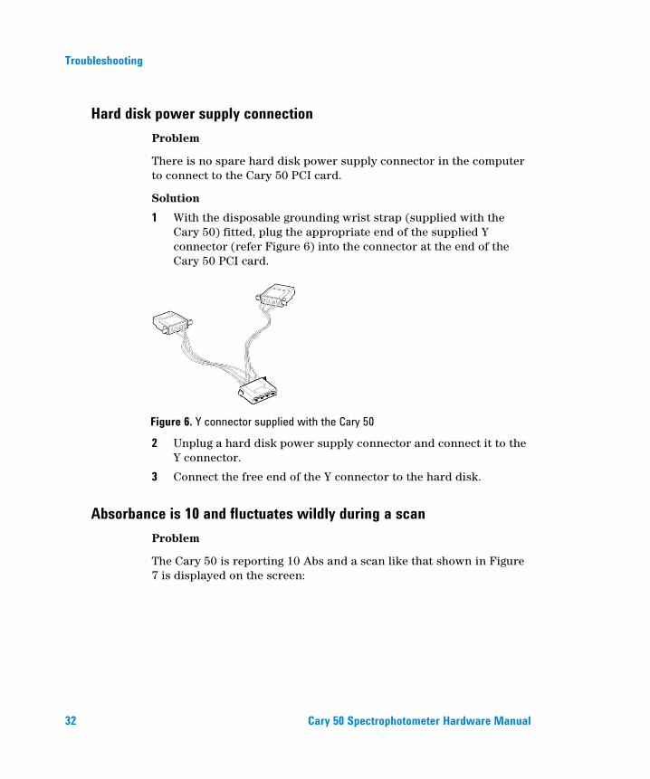
1 With the disposable grounding wrist strap (supplied with the Cary 50) fitted, plug the appropriate end of the supplied Y connector (refer Figure 6) into the connector at the end of the Cary 50 PCI card.
Figure 6. Y connector supplied with the Cary 50
2 Unplug a hard disk power supply connector and connect it to the Y connector.
3 Connect the free end of the Y connector to the hard disk.
Absorbance is 10 and fluctuates wildly during a scan
Problem
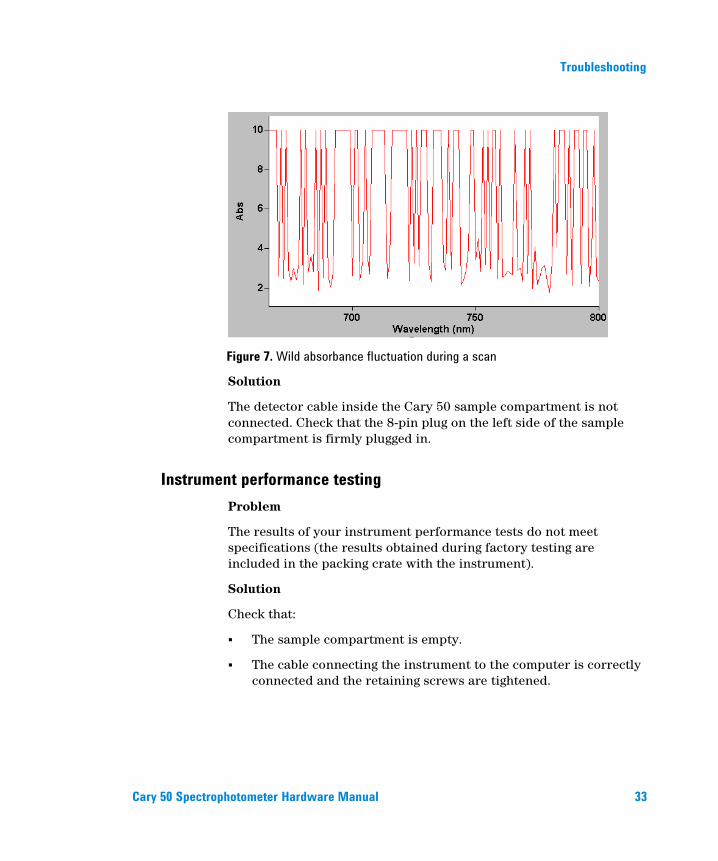
The Cary 50 is reporting 10 Abs and a scan like that shown in Figure 7 is displayed on the screen:
Troubleshooting
Cary 50 Spectrophotometer Hardware Manual 33
Figure 7. Wild absorbance fluctuation during a scan
Solution
The detector cable inside the Cary 50 sample compartment is not connected. Check that the 8-pin plug on the left side of the sample compartment is firmly plugged in.
Instrument performance testing
Problem
The results of your instrument performance tests do not meet specifications (the results obtained during factory testing are included in the packing crate with the instrument).
Solution
Check that:
The sample compartment is empty.
The cable connecting the instrument to the computer is correctly connected and the retaining screws are tightened.
Troubleshooting
34 Cary 50 Spectrophotometer Hardware Manual
The lamp is pulsing. This is indicated if the green power indicator on the front of the instrument flashes (you should also hear the monochromator and the filter wheel moving). You should also turn the instrument on its side and look through the small lamp viewing hole in the base of the instrument. If the lamp is not pulsing you may have a hardware conflict.
The lamp is correctly aligned (see Page 25 for instructions on aligning the lamp).
‘Calibrated’ appears on the ‘Calibration’ tab in System Information. To open System Information, double-click the ‘Cary WinUV’ folder (or the ‘UV Dissolution’ or ‘UV FO Dissolution’ folder) on the Windows desktop, and then double-click the ‘System Information’ icon. If the text reads ‘UnCalibrated’ on the ‘Calibration’ tabbed page, select ‘Initialize’. Wait for the instrument to finish initializing and click ‘Calibrate’. When the calibration routine finishes, the text will change to ‘Calibrated’. Your instrument is now calibrated and is ready to use.
Repeat the Instrument Performance Test suite in Validate.
WARNING
Eye and Shock Hazards
When operating, the lamp module emits high-intensity light, which can
damage eyes. To avoid eye damage, never operate the lamp module outside
the instrument.
The lamp module contains components operating at high voltages. To avoid
electric shock, NEVER disassemble the lamp module.
Troubleshooting
Cary 50 Spectrophotometer Hardware Manual 35
Wavelength calibration
Problem
The position of an absorption (transmission or reflectance) peak appears to shift over a prolonged period of time.
Solution
Perform a wavelength calibration.
Restart the computer. Agilent recommends that as part of your standard operating procedure, you restart the computer attached to the Cary 50 monthly.
Perform the Instrument Performance Test suite in ‘Validate’ to ensure the instrument results meet specification.

Troubleshooting
36 Cary 50 Spectrophotometer Hardware Manual
This page is intentionally left blank.
Spare Parts
Cary 50 Spectrophotometer Hardware Manual 37
6. Spare Parts
These spare parts are available for use with your Agilent Cary 50 spectrophotometer. Always use Agilent-supplied spare parts, unless otherwise indicated.
Part Part number
Sample compartment lid („1‟ in Figure 8) 0910127200
Sample compartment front panel („2‟ in Figure 8) 0110642990
Lamp mirror adjustment cover („3‟ in Figure 8) 0910127400
Accessory cable port plate („4‟ in Figure 8) 0910124000
Xenon lamp module 0110639690
Cary 50 PCI card 0210155790
Cary 50 computer interconnecting cable 0110637390
3M disposable grounding wrist strap 7910031300
Mouse mat 7910022300
Spare Parts
38 Cary 50 Spectrophotometer Hardware Manual
2
1
3
4
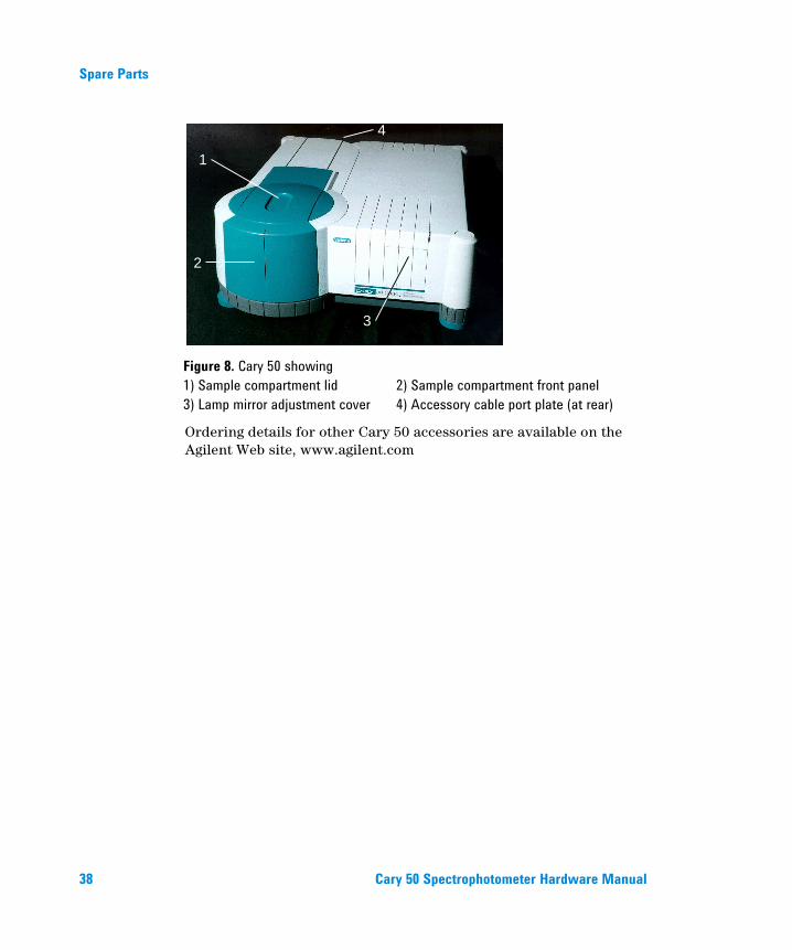
Figure 8. Cary 50 showing
1) Sample compartment lid 2) Sample compartment front panel
3) Lamp mirror adjustment cover 4) Accessory cable port plate (at rear)
Ordering details for other Cary 50 accessories are available on the Agilent Web site, www.agilent.com