Embed Size (px)
Citation preview

C/AS3
Acceptable Solution for Buildings Where Care or Detention is Provided (Risk Group SI)
For New Zealand Building Code Clauses C1-C6 Protection from Fire
Using this Acceptable Solution
The Ministry of Business, Innovation and Employment may amend parts of this Acceptable Solution at any time. People using this Acceptable Solution should check on a regular basis whether new versions have been published. The current version can be downloaded from www.dbh.govt.nz/ compliance-documents
Users should make themselves familiar with the preface to the New Zealand Building Code Handbook, which describes the status of Acceptable Solutions and explains other ways of achieving compliance.
Defined words (italicised in the text) are explained in the Building Code Clause A2 and in the Definitions section of this Acceptable Solution. Classified uses of buildings are explained in the Building Code Clause A1.
Enquiries about the content of this document should be directed to:
The Ministry of Business, Innovation and EmploymentPO Box 10-729, Wellington.Telephone 0800 242 243Fax 04 494 0290 Email: [email protected]
ISBN: 978-0-478-38172-6 (print) ISBN: 978-0-478-38173-3 (electronic)
Acceptable Solutions and Verification Methods are available from www.dbh.govt.nz/compliance-documents
© Ministry of Business, Innovation and Employment 2014
This document is protected by Crown copyright, unless indicated otherwise. The Ministry of Business, Innovation and Employment administers the copyright in this document. You may use and reproduce this document for your personal use or for the purposes of your business provided you reproduce the document accurately and not in an inappropriate or misleading context. You may not distribute this document to others or reproduce it for sale or profit.
The Ministry of Business, Innovation and Employment owns or has licences to use all images and trademarks in this document. You must not use or reproduce images and trademarks featured in this document for any purpose (except as part of an accurate reproduction of this document) unless you first obtain the written permission of the Ministry of Business, Innovation and Employment.
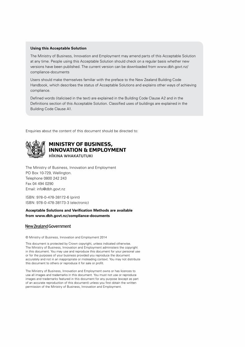
Document History
Date Alterations
New document Effective from 10 April 2012
C/AS3 is a new publication that can be used to show compliance with the Building Code Clauses C1-C6 Protection from Fire.
Amendment 1 (Errata 1)
Effective from 15 February 2013 until 18 June 2014
pp. 7–8 References pp. 13, 14, 17 Definitions p. 23 1.3 p. 24 2.2.3 p. 35 Figure 3.7 p. 39 Figure 3.12
p. 47 3.15.5 p. 78 Table 4.2 pp. 81–91 5.2.1, 5.3.2, 5.5.4, 5.8.1, Table 5.2, Figure 5.3 p. 103 C4.1.2 and C5.1.1
Amendment 2 Effective from 19 December 2013 until 28 February 2015
p. 7 References pp. 10 and 15 Definitions p. 20 Table 1.1 p. 23 1.3 p. 24, 26–27 2.2.1, 2.2.8, 2.3.1 p. 47 3.15.2
p. 56 4.4.4, 4.4.5 pp. 60–61 Figure 4.4, 4.6.5 pp. 77–79 4.16.12, 4.17.1, 4.17.6 p. 95 7.2 p. 102 B2.1.1 pp. 103–104 C6.1.2
Amendment 3 Effective from 1 July 2014
p. 7 References p. 10, 14 and 15 Definitions p. 20 1.1.1, Table 1.1 p. 23 1.3 p. 24 2.2.1 p. 30 3.3.2 p. 39 3.7.13 pp. 43–44 3.10.2, 3.10.5, 3.11.1, 3.11.5
p. 47 3.15.2 p. 53 4.2.1 p. 62 4.10.3 pp. 77–79 4.16.12, 4.17.2, 4.17.5, 4.18.2 p. 82 5.3.1 p. 87 5.6.8 p. 103 C1.1, C2.1, C4.1.2, C5.1.1 p. 107 Index
When can you use C/AS3
This Acceptable Solution is effective from 1 July 2014. It can be used to show compliance with the Building Code Clauses C1-C6 Protection from Fire. It does not apply to building consent applications submitted before 1 July 2014.
The previous version, Amendment 2, of this Acceptable Solution can be used to show compliance with the Building Code Clauses C1-C6 Protection from Fire until 28 February 2015. It can be used for building consent applications submitted before 1 March 2015.
Status of C/AS3
This Acceptable Solution C/AS3, for buildings where care or detention is provided (Risk Group SI), provides a means of compliance with the New Zealand Building Code Clauses C1-C6 Protection from Fire. It is issued under section 22 of the Building Act 2004 as an Acceptable Solution.
This Acceptable Solution is one way that can be used to show compliance with the New Zealand Building Code Clauses C1-C6 Protection from Fire. Other ways of complying with the Building Code are described, in general terms, in the preface of the New Zealand Building Code Handbook.

Page Page
Contents
References 7
Definitions 9
Part 1: General 19
1.1 Introduction and scope 19
1.2 Using this Acceptable Solution 21
1.3 Alterations and changes of use 23 to buildings
1.4 Calculating occupant loads 23
Part 2: Firecells, fire safety systems 24 and fire resistance ratings
2.1 Provision of firecells 24
2.2 Fire safety systems 24
2.3 Fire resistance ratings 27
Part 3: Means of escape 28
3.1 General principles 28
3.2 Number of escape routes 30
3.3 Height and width of escape routes 30
3.4 Length of escape routes 33
3.5 Escape from basements 37
3.6 Open paths 37
3.7 Special cases of open paths 38
3.8 Dead ends 40
3.9 Exitways 40
3.10 Control of exitway activities 43
3.11 External escape routes 43
3.12 This paragraph deliberately left blank 45
3.13 This paragraph deliberately left blank 45
3.14 This paragraph deliberately left blank 45
3.15 Doors subdividing escape routes 46
3.16 Signs 52
Part 4: Control of internal fire and 53 smoke spread
4.1 Firecells 53
4.2 Glazing in fire and smoke 53 separations
4.3 Structural stability during fire 54
4.4 Fire stopping 56
4.5 Firecell construction 56
4.6 Specific requirements for 59 sleeping areas
4.7 This paragraph deliberately 61 left blank
4.8 This paragraph deliberately 61 left blank
4.9 Exitways 61
4.10 Intermittent activities 62
4.11 Protected shafts 63
4.12 Long corridor subdivision 64
4.13 Floors 64
4.14 Subfloor spaces 66
4.15 Concealed spaces 67
4.16 Closures in fire and smoke 71 separations
4.17 Interior surface finishes, floor 78 coverings and suspended flexible fabrics
4.18 Building services plant 79
Part 5: Control of external fire spread 80
5.1 Fire separation for buildings with 80 more than one title
5.2 Horizontal fire spread from 81 external walls
5.3 FRRs of external walls 82
5.4 Small openings and fire resisting 82 glazing
5.5 Table method for external walls 82
5.6 Horizontal fire spread from roofs 86 and open sided buildings
5.7 Vertical fire spread 89
5.8 Exterior surface finishes 91
Part 6: Firefighting 92
6.1 Fire service vehicular access 92
6.2 Information for firefighters 93
6.3 Access within the building for 93 firefighting and rescue operations
6.4 Firefighting facilities 93
Part 7: Prevention of fire occurring 94
7.1 Solid fuel appliances 94
7.2 Gas-burning appliances 95
7.3 Oil-fired appliances 95
7.4 Downlights 95
7.5 Open fires 96
Contents C/AS3
DEPARTMENT OF BUILDING AND HOUSING – 10 APRIL 2012 I 5

Page
Appendix A (normative): 101 Fire safety systems
Appendix B (normative): 102 Fire sprinkler systems
Appendix C (normative): 103 Test methods
Index 106
Contents C/AS3
6 I DEPARTMENT OF BUILDING AND HOUSING – 10 APRIL 2012

References
Where quoted
For the purposes of New Zealand Building Code compliance, the New Zealand and other Standards, and other documents referred to in this Acceptable Solution (primary reference documents) shall be the editions, along with their specific amendments, listed below. Where the primary reference documents refer to other Standards or other documents (secondary reference documents), which in turn may also refer to other Standards or other documents, and so on (lower order reference documents), then the applicable version of these secondary and lower order reference documents shall be the version in effect at the date this Acceptable Solution was published.
Standards New Zealand
NZS/BS 476:- Fire tests on building materials and structures Part 21: 1987 Methods for determination of the fire resistance C5.1.1 of loadbearing elements of construction Part 22: 1987 Methods for determination of the fire resistance C5.1.1 of non-loadbearing elements of construction
AS/NZS 1668:- The use of ventilation and air conditioning in buildings Part 1: 1998 Fire and smoke control in multi-compartment 4.16.12, Table 2.1, buildings A2.1.1 Amend: 1
AS/NZS 2918: 2001 Domestic solid fuel burning appliances 7.1.1, 7.1.2, 7.3.3, – installation 7.5.5, 7.5.10 Comment, 7.5.12, Figure 7.2
NZS 4232:- Performance criteria for fire resisting closures Part 2: 1988 Fire resisting glazing systems Definitions
NZS 4332: 1997 Non-domestic passenger and goods lifts 6.4.3
NZS 4510: 2008 Fire hydrant systems for buildings Table 2.1, A2.1.1 Amend: 1
NZS 4512: 2010 Fire detection and alarm systems in buildings 2.2.1, Table 2.1, 6.2.1, A2.1.1, C6.1.6
NZS 4515: 2009 Fire sprinkler systems for life safety in sleeping Definitions, 2.2.1, occupancies (up to 2000 m2) 6.2.1, B3.1.1
NZS 4520: 2010 Fire resistant doorsets 4.2.4, 4.16.6, C6.1.1
NZS 4541: 2013 Automatic fire sprinkler systems Definitions, 2.2.1, Table 2.1, 5.2.2, 6.2.1, B2.1.1
AS/NZS 5601:- Gas installation 7.2.1, 7.2.2 Part 1: 2010 General installations Amend: 1
Standards Australia
AS 1366:- Rigid cellular plastics sheets for thermal insulation Part 1: 1992 Rigid cellular polyurethane (RC/PUR) 4.17.2 Amend: 1 Part 2: 1992 Rigid cellular polyisocyanurate (RC/PIR) 4.17.2 Part 3: 1992 Rigid cellular polystyrene – moulded (RC/PS-M) 4.17.2 Amend: 1 Part 4: 1989 Rigid cellular polystyrene – extruded (RC/PS-E) 4.17.2
References C/AS3
MINISTRY OF BUSINESS, INNOVATION AND EMPLOYMENT – 1 JULY 2014 I 7
Errata 1Feb 2013
Amend 2 Dec 2013
Amend 3Jul 2014

AS 1530:- Methods for fire tests on building materials, components and structures Part 1: 1994 Combustibility test for materials Definitions, C3.1, C4.1.1 Part 2: 1993 Test for flammability of materials 4.17.8 Part 4: 2005 Fire-resistance tests of elements of building 4.5.9, C5.1.1 construction
AS 1691: 1985 Domestic oil-fired appliances – installation 7.3.1, 7.3.2
AS 4072:- Components for the protection of openings in fire-resistant separating elements Part 1: 2005 Service penetrations and control joints C5.1.2 Amend: 1
International Standards Organisation
ISO 5660:- Reaction-to-fire tests – Heat release, smoke production and mass loss rate Part 1: 2002 Heat release rate (cone calorimeter method) C4.1.2, C7.1.1, C7.1.2 Part 2: 2002 Smoke production rate (dynamic measurement) C4.1.2
ISO 9239:- Reaction to fire tests for flooring Part 1: 2010 Determination of the burning behaviour using 4.17.3, Table 4.2, a radiant heat source. C2.1
ISO 9705: 1993 Fire tests – Full scale room test for surface products C4.1.2
European Standards Organisation
BS EN 12101:- Smoke and heat control systems Part 1: 2005 Specification for smoke barriers Definitions
Building Research Establishment (UK)
BRE Defect Action Sheet DAS 131: May 1989 5.7.18 Comment External walls: Combustible external plastics insulation: Horizontal fire barriers
BRE Report 135: 1988 Fire performance of external thermal insulation 5.7.18 Comment for walls in multi-storey buildings. Rogowski B.F., Ramaprasad R., Southern J.R.
National Fire Protection Association of America
NFPA 285: 1998 Standard method of test for the evaluation of 5.8.2 flammability characteristics of exterior non-load- bearing wall assemblies containing components using the intermediate scale, multi-storey test apparatus
American Society for Testing and Materials
ASTM D 2898: 2010 Standard practice for accelerated weathering C7.1.3 of fire-retardant-treated wood for fire testing
New Zealand Legislation
Fire Safety and Evacuation of Buildings Regulations 2006 Definitions
Hazardous Substances and New Organisms Act 1996 1.1.5
References C/AS3
Where quoted
8 I MINISTRY OF BUSINESS, INNOVATION AND EMPLOYMENT – 15 FEBRUARY 2013
Errata 1Feb 2013
Errata 1Feb 2013
Errata 1Feb 2013
Errata 1Feb 2013

Definitions
The full list of definitions for italicised words may be found in the New Zealand Building Code Handbook.
Access route A continuous route that permits people and goods to move between the apron or construction edge of the building to spaces within a building, and between spaces within a building.
Accessible Having features to permit use by people with disabilities.
Accessible route An access route usable by people with disabilities. It shall be a continuous route that can be negotiated unaided by a wheelchair user. The route shall extend from street boundary or car parking area to those spaces within the building required to be accessible to enable people with disabilities to carry out normal activities and processes within the building.
Adjacent building A nearby building, including an adjoining building, whether or not erected on other property.
Basement Any firecell or part of a firecell below the level of the lowest final exit.
Comment:Because fire safety systems are increased with increases in escape height, the precautions for basements increase with basement depth. Thus a single floor building with one basement level is treated as a two floor building, a single floor building with three basement levels as a four floor building.
Boundary means any boundary that is shown on a survey plan that is approved by the Surveyor-General and deposited with the Registrar-General of Land, whether or not a new title has been issued.
Building has the meaning given to it by sections 8 and 9 of the Building Act 2004.
Comment:Notwithstanding the definition of building, a number of separated buildings cannot be taken as a single firecell for the purposes of this Acceptable Solution.
Building Act 2004 (the Building Act) means the principal legislation dealing with building controls in New Zealand.
Comment:The Building Act applies to the construction, alteration, and demolition of new and existing buildings throughout New Zealand.
Building Code means the regulations made under section 400 of the Building Act 2004.
Building consent means consent to carry out building work granted by a building consent authority under section 49 of the Building Act 2004.
Building consent authority has the meaning ascribed to it by section 7 of the Building Act 2004.
Building element Any structural and non-structural component or assembly incorporated into or associated with a building. Included are fixtures, services, drains, permanent mechanical installations for access, glazing, partitions, ceilings and temporary supports.
Building height Building height means the vertical distance between the floor level of the lowest occupied space above the ground and the top of the highest occupied floor, but not including spaces located within or on the roof that enclose stairways, lift shafts, or machinery rooms.
Cavity barrier A construction provided to close openings within a concealed space against the passage of fire, or to restrict the spread of fire within such spaces.
Chimney A non-combustible structure which encloses one or more flues, fireplaces or other heating appliances.
Chimney back The non-combustible wall forming the back of a fireplace.
Definitions C/AS3
DEPARTMENT OF BUILDING AND HOUSING – 10 APRIL 2012 I 9

Chimney breast The front fireplace wall construction above the fireplace opening.
Chimney jambs The side walls of a fireplace.
Combustible See non-combustible.
Concealed space Any part of the space within a building that cannot be seen from an occupied space.
Comment:This term includes any ceiling space, roof space, space under a raised floor (such as computer rooms, floors, or stages), plenums, spaces under a tiered floor, “left-over spaces” created when some structural element or the like has been covered in; small service or duct spaces within the volume of a firecell and the like, but not a protected shaft.
Construct in relation to a building, includes to design, build, erect, prefabricate, and relocate the building; and construction has a corresponding meaning.
Damper blade A component of a fire damper that closes off the airway within a fire damper upon detection of fire or smoke.
Dead end That part of an open path where escape is possible in only one direction.
Comment:A dead end ceases to exist where the escape route reaches a point in the open path which offers alternative directions of travel, or at a final exit or an exitway.
Doorset A complete assembly comprising a door leaf or leaves including any glazed or solid panels adjacent to or over the leaves within the door frame including hardware or other inbuilt features; and a door frame, if any, with its fixings to the wall and, for a sliding or tilting door, all guides and their respective fixings to the lintel, wall or sill.
Early childhood centre (ECC) means premises used regularly for the education or care of 3 or more children (not being children of the persons providing the education or care, or children enrolled at a school being provided with education or care before or after school) under the age of six—
a) by the day or part of a day; but
b) not for any continuous period of more than seven days.
ECC does not include home based early childhood services.
Escape height The height between the floor level in the firecell being considered and the floor level of the required final exit which is the greatest vertical distance above or below that firecell.
Comment:1. It is necessary only to use the greatest height to
the exits required for the firecell being considered, even though the building may have other final exits at lower or higher levels.
2. Where the firecell contains intermediate floors, or upper floors within household units the escape height shall be measured from the floor having the greatest vertical separation from the final exit.
Escape route A continuous unobstructed route from any occupied space in a building to a final exit to enable occupants to reach a safe place, and shall comprise one or more of the following: open paths and safe paths.
Comment: Doors are not obstructions in an escape route provided they comply with C/AS1–C/AS7 and D1/AS1.
Exitway All parts of an escape route protected by fire or smoke separations, or by distance when exposed to open air, and terminating at a final exit.
External wall Any exterior face of a building within 30° of vertical, consisting of primary and/or secondary elements intended to provide protection against the outdoor environment, but which may also contain unprotected areas.
Comment:A roof is an external wall if within 30° of the vertical.
Final exit The point at which an escape route terminates by giving direct access to a safe place.
Definitions C/AS3
10 I MINISTRY OF BUSINESS, INNOVATION AND EMPLOYMENT – 1 JULY 2014
Amend 2 Dec 2013
Amend 3Jul 2014
Comment:Final exits are commonly the external doors from a ground floor, but this applies only if such doors open directly onto a safe place. If a safe place can be reached only by passing down an alley, or across a bridge, then the final exit is not reached until the end of such an alley or bridge. Final exits, therefore, should be seen strictly as a point of arrival, rather than as any particular element of a building. They are determined entirely by the definition of safe place.
Fire The state of combustion during which flammable materials burn producing heat, toxic gases, or smoke or flame or any combination of these.
Firecell Any space including a group of contiguous spaces on the same or different levels within a building, which is enclosed by any combination of fire separations, external walls, roofs, and floors.
Comment:Floors, in this context, includes ground floors, and those in which the underside is exposed to the external environment (eg, when cantilevered). Note also that internal floors between firecells are fire separations.
Fire damper A device with a specified FRR complete with fixings and operating mechanism for automatically closing off an airway where it passes through a fire separation.
Comment:An airway may be a duct, plenum, ceiling space, roof space or similar construction used for the passage of ventilating air.
Fire door A doorset, single or multi-leaf, having a specific fire resistance rating, and in certain situations a smoke control capability, and forming part of a fire separation. The door, in the event of fire, if not already closed, will close automatically and be self latching.
Fire hazard means the danger of potential harm and degree of exposure arising from—
a) the start and spread of fire; and
b) the smoke and gases that are generated by the start and spread of fire.
Fire load The sum of the net calorific values of the combustible contents which can reasonably be expected to burn within a firecell, including furnishings, built-in and removable materials, and building elements. The calorific values shall be determined at the ambient moisture content or humidity. (The unit of measurement is MJ.)
Fireplace A space formed by the chimney back, the chimney jambs, and the chimney breast in which fuel is burned for the purpose of heating the room into which it opens.
Fire resistance rating (FRR) The term used to describe the minimum fire resistance required of primary and secondary elements as determined in the standard test for fire resistance, or in accordance with a specific calculation method verified by experimental data from standard fire resistance tests. It comprises three numbers giving the time in minutes for which each of the criteria structural adequacy, integrity and insulation are satisfied, and is presented always in that order.
Comment:Examples of FRRs are:
a) 60/60/30 indicating structural adequacy 60 minutes, integrity 60 minutes, insulation 30 minutes.
b) 30/- /- indicating structural adequacy 30 minutes, but no time requirement for integrity or insulation.
c) 60/30/x indicating structural adequacy of 60 minutes, integrity of 30 minutes, and a requirement for insulation.
Definitions C/AS3
DEPARTMENT OF BUILDING AND HOUSING – 10 APRIL 2012 I 11
Fire resisting closure A fire rated device or assembly for closing an opening through a fire separation.
Comment:A fire resisting closure is intended to include fire doors, fire windows or access panels. In this context the opening may be used to permit passage of people or goods, or to transmit light, but does not include an opening to permit the passage of building services.
Fire resisting glazing Fixed or openable glazing, complete with frame and fixings, mullions, transoms and glazing beads, with a specified FRR and complying with NZS 4232: Part 2.
Comment:1. The requirement for fire resisting glazing will not be
met by ordinary window glass, or safety glasses, but rather by wired glass, or by special fire resisting glass shown by test to perform. The nature and design of the frames also have an effect on the performance of fire resisting glazing.
2. Openable glazing is required by NZS 4232 Part 2 to be fitted with an automatic device which, in the event of fire, will close and latch the window sash.
Fire retardant A substance or a treatment, incorporated in or applied to a material, which suppresses or delays the combustion of that material under specified conditions.
Fire safety systems means the combination of all active and passive protection methods used in a building to—
(a) warn people of an emergency; and
(b) provide for safe evacuation; and
(c) provide for access by, and the safety of, firefighters; and
(d) restrict the spread of fire; and
(e) limit the impact of fire on structural stability
Fire separation Any building element which separates firecells or firecells and safe paths, and provides a specific fire resistance rating.
Fire shutter A fire rated device, complete with fixings and operating mechanism, for automatically closing off an opening in a fire separation or protected shaft.
Fire stop A material or method of construction used to restrict the spread of fire within or through fire separations, and having a FRR no less than that of the fire separation.
Comment:Fire stops are mainly used to seal around penetrations, but can also be used to seal narrow gaps between building elements.
Fixture An article intended to remain permanently attached to and form part of a building.
Flammability index (FI) That index number for flammability, which is determined according to the standard test method for flammability of thin flexible materials.
Flue The passage through which the products of combustion are conveyed to the outside.
Flue liner Pipes or linings of fire clay, metal or fire brick that surrounds flues.
Flue system A series of interconnecting flue pipe casings which form a safe passage (flue) for conveying products of combustion from within an appliance to the outside of a building or structure.
Definitions C/AS3
12 I DEPARTMENT OF BUILDING AND HOUSING – 10 APRIL 2012

Foamed plastics Combustible foamed plastic polymeric materials of low density (typically less than 100 kg/m3) and are classified as cellular polymers which are manufactured by creating a multitude of fine void (typically 90 to 98%) distributed more or less uniformly throughout the product. Examples of foamed plastics are latex foams, polyethylene foams, polyvinyl chloride foams, expanded or extruded polystyrene foams, phenolic foams, ureaformaldehyde foams, polyurethane foams and polychloropene foams.
Comment:1. Foamed plastics may be rigid or flexible, but rigid
foams are the most common in building products. When burnt they tend to generate high levels of heat energy (kJ/kg) and varying quantities of smoke and other toxic gases depending on the nature and volume of the particular product.
2. Where doubt exists as to whether a building material is foamed plastics, an opinion should be sought from a person or organisation with appropriate skill and experience in fire engineering. That opinion should be included with the building consent application to the building consent authority.
Group Number The classification number for a material used as a finish, surface, lining, or attachment to a wall or ceiling within an occupied space and determined according to the standard test methods for measuring the properties of lining materials.
Comment:The method for determining a Group Number is described in C/VM2 Appendix A.
Group sleeping area A firecell containing communal sleeping accommodation for a specified number of people who may or may not be known to one another. Partial subdivision within the firecell is permitted with specific limitation including that no occupied space is fully enclosed and all occupied spaces are open and available to all occupants at any time. A group sleeping area firecell may include spaces for associated direct support functions, such as hygiene facilities and tea making (not cooking) activities, for use by the occupants. It does not include spaces, such as waiting rooms, lounges, dining rooms or kitchens, providing a communal service function for all occupants.
Comment:1. Examples of group sleeping area firecells are
dormitories, hospital wards, wharenui, backpacker hostels and ski lodges.
2. The maximum number of people permitted in a group sleeping area firecell, and the permitted form of subdivision, will depend on the ability of the occupants to react to the presence of fire and escape to a safe place.
Handrail A rail to provide support to, or assist with the movement of a person.
Hazardous Creating an unreasonable risk to people of bodily injury or deterioration of health.
Hazardous substance has the meaning ascribed to it by section 2 of the Fire Service Act 1975 and section 2 of the Hazardous Substances and New Organisms Act 1996.
Hearth The insulating floor under the fire and in front and at the sides of the fireplace.
Hold-open device A device which holds a smoke control door or fire door open during normal use, but is released by deactivating the device by an automatic fire detection system, allowing the door to close automatically under the action of a self-closing device.
Household unit
(a) means a building or group of buildings, or part of a building or group of buildings, that is—
(i) used, or intended to be used, only or mainly for residential purposes; and
(ii) occupied, or intended to be occupied, exclusively as the home or residence of not more than 1 household; but
(b) does not include a hostel, boarding house, or other specialised accommodation.
HVAC An abbreviation for heating, ventilating and airconditioning.
Insulating material A material that has a thermal conductivity of less than 0.07 W/mK.
Insulation In the context of fire protection, the time in minutes for which a prototype specimen of a fire separation, when subjected to the standard test for fire resistance, has limited the transmission of heat through the specimen.
Definitions C/AS3
MINISTRY OF BUSINESS, INNOVATION AND EMPLOYMENT – 15 FEBRUARY 2013 I 13
Errata 1Feb 2013
Errata 1Feb 2013

Integrity In the context of fire protection, the time in minutes for which a prototype specimen of a fire separation, when subjected to the standard test for fire resistance, has prevented the passage of flame or hot gases.
Comment:The precise meaning of integrity depends on the type of building elements being treated and how it is defined in the standard test being used.
Intended use In relation to a building,—
(a) includes any or all of the following:
(i) any reasonably foreseeable occasional use that is not incompatible with the intended use:
(ii) normal maintenance:
(iii) activities undertaken in response to fire or any other reasonably foreseeable emergency; but
(b) does not include any other maintenance and repairs or rebuilding.
Intermediate floor Any upper floor within a firecell which because of its configuration provides an opening allowing smoke or fire to spread from a lower to an upper level within the firecell.
Comment:1. Upper floors within household units need not meet
the specific fire safety requirements which apply to intermediate floors in all other situations.
2. An intermediate floor may be open to the firecell or enclosed with non-fire rated construction. If enclosed with fire rated walls another firecell is created.
3. Household units occur only in risk groups SM and SH. Life safety provisions are governed by the limitations in permitted open path lengths.
4. Risk groups SM, SI, CA, WB, WS and VP allow limited area intermediate floors of 20% or 40% of the floor area depending on other fire safety requirements. In other situations C/VM2 is to be used.
Life rating The fire resistance rating to be applied to elements of construction that allows movement of people from their location in a building to a safe place.
Means of escape from fire In relation to a building that has a floor area,—
a) means continuous unobstructed routes of travel from any part of the floor area of that building to a place of safety; and
b) includes all active and passive protection features required to warn people of fire and to assist in protecting people from the effects of fire in the course of their escape from the fire.
Comment:Means of escape include features providing visibility in escape routes complying with F6 and signs complying with F8.
Non-combustible Materials shall be classified as combustible or non-combustible when tested to AS 1530 Part 1.
Notional boundary The boundary which for fire safety purposes, is assumed to exist between two buildings on the same property under a single land title.
Comment: The notional boundary is assumed to exist in the space between the buildings and is positioned so that each of the buildings would comply with the provisions of the space separation having regards to the amount of its unprotected area. In practise if one of the buildings is existing, the position of the boundary will be set by the space separation factors for that building.
1. The siting of the new building which is adjacent to the existing building can be checked to see that it also complies, using a revised notional boundary location that is no closer than 1.0 metre from the existing building.
2. Where both buildings are new it is allowable to move the notional boundary between buildings. However in assessing fire spread from one building to the other and vice versa, the notional boundary should not be located any closer than 1.0 metre from the building that is receiving the radiation.
Occupant load The greatest number of people likely to occupy a particular space within a building. It is determined by:
a) dividing the total floor area by the m2 per person (occupant density) for the activity being undertaken, or
b) for sleeping areas, counting the number of sleeping (or care) spaces, or
c) for fixed seating areas, counting the number of seats.
Comment:See Paragraphs 1.4.5 (for fixed seating) and 1.4.6 (for sleeping areas) where appropriate.
Errata 1Feb 2013
Definitions C/AS3
14 I MINISTRY OF BUSINESS, INNOVATION AND EMPLOYMENT – 1 JULY 2014
Amend 3Jul 2014
Occupied space Any space within a building in which a person will be present from time to time during the intended use of the building.
Open path That part of an escape route (including dead ends) within a firecell where occupants may be exposed to fire or smoke while making their escape.
Open space Open space means land on which there are, and will be, no buildings and which has no roof over any part of it other than overhanging eaves.
Other property Any land or buildings or part of any land or buildings, that are:
a) not held under the same allotment; or
b) not held under the same ownership; and includes a road.
Owner In relation to land and any buildings on the land,—
(a) means the person who—
(i) is entitled to the rack rent from the land; or
(ii) would be so entitled if the land were let to a tenant at a rack rent; and
(b) includes—
(i) the owner of the fee simple of the land; and
(ii) for the purposes of Building Act 2004 sections 32, 44, 92, 96, 97, and 176(c), any person who has agreed in writing, whether conditionally or unconditionally, to purchase the land or any leasehold estate or interest in the land, or to take a lease of the land, and who is bound by the agreement because the agreement is still in force.
Penetration A building element passing through an opening in a fire separation.
Comment:A penetration may include, but is not limited to: pipes, cables, ducts, hoses, drains, cable trays, ropes, data outlets, power outlets, hatches, glazing, structural bracing etc.
People with disabilities People whose ability to use buildings is affected by mental, physical, hearing or sight impairment.
Place of safety Place of safety means either—
(a) a safe place; or
(b) a place that is inside a building and meets the following requirements:
(i) the place is constructed with fire separations that have fire resistance sufficient to withstand burnout at the point of the fire source; and
(ii) the place is in a building that is protected by an automatic fire sprinkler system that complies with NZS 4541 or NZS 4515 as appropriate to the building’s use; and
(iii) the place is designed to accommodate the intended number of persons; and
(iv)the place is provided with sufficient means of escape to enable the intended number of persons to escape to a safe place that is outside a building.
Primary element A building element providing the basic loadbearing capacity to the structure, and which if affected by fire may initiate instability or premature structural collapse.
Comment:Suspended floors in multi-storey buildings are primary elements.
Property rating The fire resistance rating to be applied to elements of construction that allows for protection of other property.
Protected shaft A space, other than a safe path, enclosed by fire separations or external walls used to house building services, lifts, or conveyors which pass from one firecell to another.
Railway line has the meaning ascribed to it by section 4 of the Railways Act 2005.
Amend 2Dec 2013
Amend 3Jul 2014
Definitions C/AS3
MINISTRY OF BUSINESS, INNOVATION AND EMPLOYMENT – 19 DECEMBER 2013 I 15
Relevant boundary Relevant boundary means the boundary of an allotment that is other property in relation to the building in question and from which is measured the separation between the building and that other property; and for the external wall of any building, the relevant boundary is the nearest of—
(a) a boundary of a freehold allotment, except that if the other property is a road, railway line, or public open space, the relevant boundary is the boundary on the far side of that other property; or
(b) a boundary of a cross-lease or a company lease or a licence, except that if the other property is open space to which the lessee or licensee of the building in question has an exclusive right of access and occupation or to which 2 or more occupiers of the building in question have rights of access and occupation, the relevant boundary is the boundary on the far side of that other property; or
(c) a boundary shown on a unit plan (but excluding a boundary between a principal unit and its accessory unit), except that if the other property is open space and is common property, the relevant boundary is the boundary on the far side of that other property.
Comment:1. Where an easement, such as a right of way, occurs
within an allotment, the relevant boundary shall remain the same as if the easement did not exist.
2. Boundaries within a cross-lease or company lease or licence are shown on a survey plan. In some cases the boundary is the external wall or roof of a building.
3. The unit title boundaries of principal units, accessory units, and common property are shown in the unit plan. A boundary is frequently an internal or external wall, an upper floor, or the roof of a building.
4. A wall along a boundary between two allotments is called a “party wall” when the owners of the allotments each have legal rights in respect of that wall registered by way of easements on one or both titles. An internal wall between cross-leases, company leases, or unit titles, or between one of them and common property, is not generally called a party wall but in that case also the lessees, unit title holders, or corporate body concerned each have legal rights in respect of that wall. Such a wall separates areas which are other property in relation to each other, but the wall itself is part of each property. The fire protection consequence of that legal concept is that such a wall can be regarded as a fire separation providing protection against horizontal fire spread in each direction. In other words, that wall may provide the appropriate FRR instead of each property having its own wall of that FRR.
Risk group The classification of a building or firecells within a building according to the use to which it is intended to be put.
Road This term has the meaning ascribed to it by section 315 of the Local Government Act 1974 and includes a public place and also includes a motorway.
Safe path That part of an exitway which is protected from the effects of fire by fire separations, external walls, or by distance when exposed to open air.
Definitions C/AS3
16 I DEPARTMENT OF BUILDING AND HOUSING – 10 APRIL 2012

Safe place A place, outside of and in the vicinity of a single building unit, from which people may safely disperse after escaping the effects of a fire. It may be a place such as a street, open space, public space or an adjacent building unit.
Comment: The Fire Safety and Evacuation of Buildings Regulations 2006 use the term place of safety and allow the place of safety to be within the building provided that it is protected with a sprinkler system. In this Acceptable Solution a place of safety can only be within a building in Risk Group SI.
Secondary element A building element not providing load bearing capacity to the structure and if affected by fire, instability or collapse of the building structure will not occur.
Smokecell A space within a building which is enclosed by an envelope of smoke separations, or external walls, roofs, and floors.
Smoke control door A doorset that complies with Appendix C, C6.1.2 of this acceptable solution.
Smoke lobby That portion of an escape route within a firecell that precedes a safe path or an escape route through an adjoining building which is protected from the effects of smoke by smoke separations.
Smoke separation Any building element able to prevent the passage of smoke between two spaces. Smoke separations shall:
a) Be a smoke barrier complying with BS EN 12101 Part 1, or
b) Consist of rigid building elements capable of resisting without collapse:
i) a pressure of 0.1 kPa applied from either side, and
ii) self weight plus the intended vertically applied live loads, and
c) Form an imperforate barrier to the spread of smoke, and
d) Be of non-combustible construction, or achieve a FRR of 10/10/-, except that non-fire resisting glazing may be used if it is toughened or laminated safety glass.
Comment:The pressure requirement is to ensure rigidity and is not a smoke leakage requirement.
Walls and floors, whether constructed of sheet linings fixed to studs or joists, or of concrete, glazing, metal or fired clay, need only be inspected by someone experienced in building construction to judge whether the construction is tight enough to inhibit the passage of smoke.
Item d) is intended to ensure that the smoke separation will continue to perform as an effective barrier when exposed to fire or smoke for a short period during fire development.
There is no requirement for smoke control doors or other closures in smoke separations to meet the provisions of item d).
Stability In the context of fire protection is the support provided to a building element having a FRR, intended to avoid premature failure due to structural collapse as a result of applied load, dead and live loads or as a result of any additional loads caused by fire.
Stairway A series of steps or stairs with or without landings, including all necessary handrails and giving access between two different levels.
Standard test A test method which is recognised as being appropriate for the fire protection properties being assessed.
Comment: A list of standard test methods is given in Appendix C.
Structural adequacy In the context of the standard test for fire resistance, is the time in minutes for which a prototype specimen has continued to carry its applied load within defined deflection limits.
Comment: The fire design load should be as specified in B1/VM1.
Errata 1Feb 2013
Definitions C/AS3
MINISTRY OF BUSINESS, INNOVATION AND EMPLOYMENT – 15 FEBRUARY 2013 I 17

Suite A firecell providing residential accommodation for the exclusive use of one person or of several people known to one another. It comprises one or more rooms for sleeping and may include spaces used for associated domestic activities such as hygiene and cooking.
Comment:1. Bed numbers are limited to six in risk group
SI or 12 in risk group SM in accordance with C/AS2 and C/AS3. Examples may be found in hotels, motels and residential care facilities, such as old people’s homes or in hospices providing temporary family accommodation.
2. It is assumed that the social cohesion of the occupants by virtue of the personal relationship (as family members, friends or associates) would ensure that any individual, becoming aware of fire, would naturally assist others within the firecell to escape. The term suite does not apply to a group of bedrooms where each room is available to different “key-holders”. In some cases a suite may be a single bedroom.
Surface finish The combination of a surface coating and substrate material on surfaces of building elements exposed to view. It can be an applied decorative coating or the uncoated building element itself. For interior surfaces the requirements are evaluated in terms of a Group Number. For exterior surfaces the requirements are evaluated in terms of rate of heat release as determined by Appendix C, Paragraph C6.1.
Travel distance The length of the escape route as a whole or the individual lengths of its parts, namely:a) open paths and
b) safe paths.
Unprotected area In relation to an external wall of a building, this means:
a) Any part of the external wall which is not fire rated or has less than the required FRR, and
b) Any part of the external wall which has combustible material more than 1.0 mm thick attached or applied to its external face, whether for cladding or any other purpose.
Comment: Unprotected area includes non-fire rated windows, doors, or other openings, and non-fire rated external wall construction.
Wharenui A communal meeting house having a large open floor area used for both assembly and sleeping in the traditional Maori manner.
Definitions C/AS3
18 I DEPARTMENT OF BUILDING AND HOUSING – 10 APRIL 2012
CONTENTS
1.1 Introduction and scope
1.2 Using this Acceptable Solution
1.3 Alterations and changes of use to buildings
1.4 Calculating occupancy loads
Part 1: General
1.1 Introduction and scope
This Acceptable Solution can be used for establishing compliance with NZBC C1 to C6 Protection from Fire. It is one of a suite of Acceptable Solutions C/AS1 to C/AS7, each of them corresponding to a risk group (summarised in Table 1.1 and defined in Paragraph 1.1.1.
If the uses of a building, or part of a building, cover more than one risk group, one or more of these Acceptable Solutions may need to be followed to demonstrate compliance. Paragraph 1.2 explains how to determine the relevant risk groups for the building activities.
Notes shown under ‘Comment’, occurring throughout this document, are for guidance purposes only and do not form part of this Acceptable Solution. Words in italic are defined at the front of this document. For ease of use, paragraphs, tables and figures containing similar information are allocated the same reference numbers in each of the Acceptable Solutions. If there is no corresponding information in a particular Acceptable Solution, the numbering is preserved by the notation:
1)“THIS PARAGRAPH DELIBERATELY LEFT BLANK”
2) “This table not required for this Acceptable Solution”
3) Figures are omitted without notification.
Appendices to this Acceptable Solution are part of and have equal status to this Acceptable Solution.
Comment:It is recommended that the commentary document for Acceptable Solutions C/AS1 to C/AS7 be read in conjunction with this Acceptable Solution.
Acceptable Solution C/AS3
DEPARTMENT OF BUILDING AND HOUSING – 10 APRIL 2012 I 19
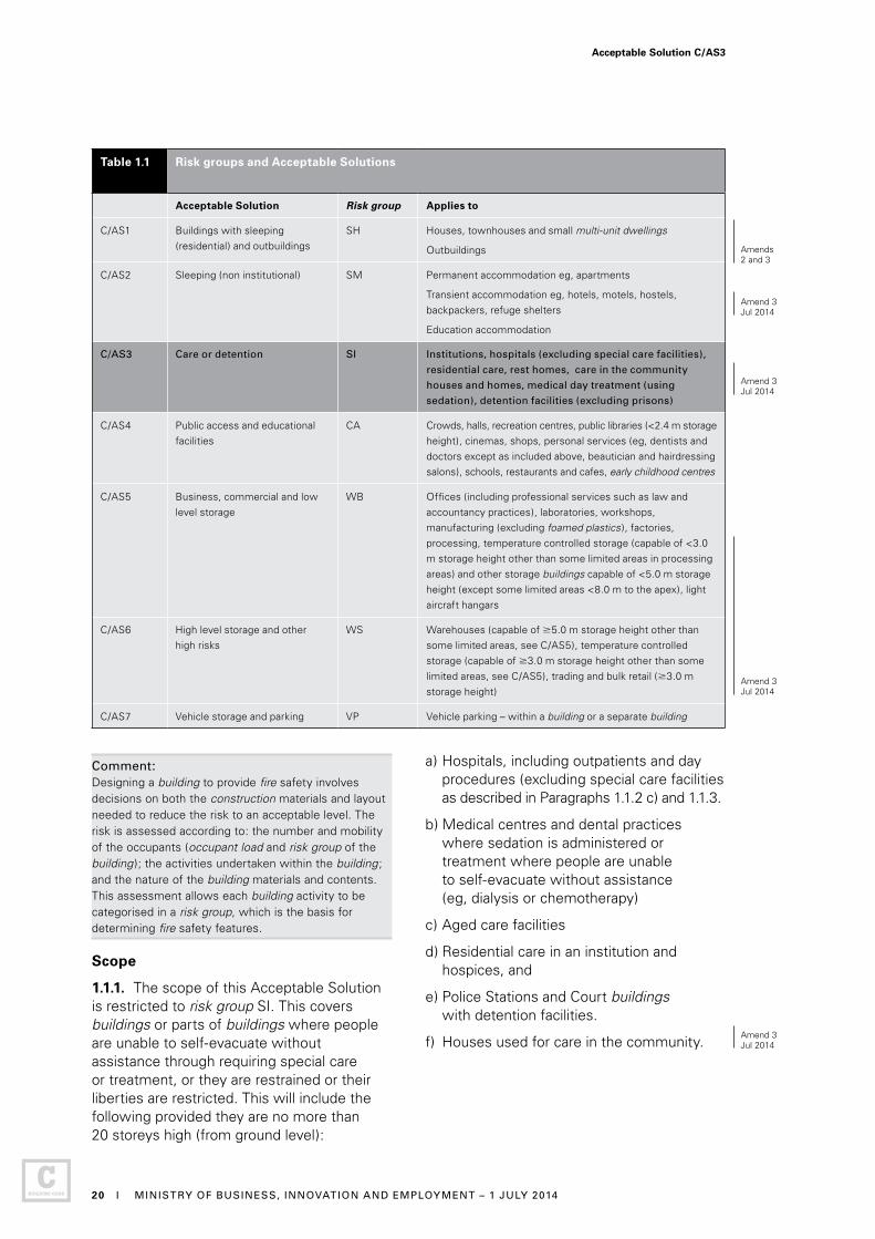
Table 1.1 Risk groups and Acceptable Solutions
Acceptable Solution Risk group Applies to
C/AS1 Buildings with sleeping (residential) and outbuildings
SH Houses, townhouses and small multi-unit dwellings
Outbuildings
C/AS2 Sleeping (non institutional) SM Permanent accommodation eg, apartments
Transient accommodation eg, hotels, motels, hostels, backpackers, refuge shelters
Education accommodation
C/AS3 Care or detention SI Institutions, hospitals (excluding special care facilities),
residential care, rest homes, care in the community
houses and homes, medical day treatment (using
sedation), detention facilities (excluding prisons)
C/AS4 Public access and educational facilities
CA Crowds, halls, recreation centres, public libraries (<2.4 m storage height), cinemas, shops, personal services (eg, dentists and doctors except as included above, beautician and hairdressing salons), schools, restaurants and cafes, early childhood centres
C/AS5 Business, commercial and low level storage
WB Offices (including professional services such as law and accountancy practices), laboratories, workshops, manufacturing (excluding foamed plastics ), factories, processing, temperature controlled storage (capable of <3.0 m storage height other than some limited areas in processing areas) and other storage buildings capable of <5.0 m storage height (except some limited areas <8.0 m to the apex), light aircraft hangars
C/AS6 High level storage and other high risks
WS Warehouses (capable of 5.0 m storage height other than some limited areas, see C/AS5), temperature controlled storage (capable of 3.0 m storage height other than some limited areas, see C/AS5), trading and bulk retail (3.0 m storage height)
C/AS7 Vehicle storage and parking VP Vehicle parking – within a building or a separate building
Comment:Designing a building to provide fire safety involves decisions on both the construction materials and layout needed to reduce the risk to an acceptable level. The risk is assessed according to: the number and mobility of the occupants (occupant load and risk group of the building ); the activities undertaken within the building; and the nature of the building materials and contents. This assessment allows each building activity to be categorised in a risk group, which is the basis for determining fire safety features.
Scope
1.1.1. The scope of this Acceptable Solution is restricted to risk group SI. This covers buildings or parts of buildings where people are unable to self-evacuate without assistance through requiring special care or treatment, or they are restrained or their liberties are restricted. This will include the following provided they are no more than 20 storeys high (from ground level):
a) Hospitals, including outpatients and day procedures (excluding special care facilities as described in Paragraphs 1.1.2 c) and 1.1.3.
b) Medical centres and dental practices where sedation is administered or treatment where people are unable to self-evacuate without assistance (eg, dialysis or chemotherapy)
c) Aged care facilities
d) Residential care in an institution and hospices, and
e) Police Stations and Court buildings with detention facilities.
f) Houses used for care in the community.
Amends2 and 3
Acceptable Solution C/AS3
20 I MINISTRY OF BUSINESS, INNOVATION AND EMPLOYMENT – 1 JULY 2014
Amend 3Jul 2014
Amend 3Jul 2014
Amend 3Jul 2014
Amend 3Jul 2014

Outside the scope of this Acceptable Solution
1.1.2. Buildings or parts of buildings in risk groups other than SI are outside the scope of this Acceptable Solution. Refer to Table 1.1 and use the corresponding Acceptable Solution instead.
Buildings with complex features are outside the scope of this Acceptable Solution and also of Acceptable Solutions C/AS1 to C/AS7 corresponding to other risk groups. Verification Method C/VM2 shall be used instead. Complex features include:
a) Atriums
b) Intermediate floors, other than limited area intermediate floors
c) Operating theatres, hyperbaric chambers
d) Buildings more than 20 storeys high, and
e) Prisons.
Buildings that require specific fire engineering design (ie, those requiring design calculations and modelling) also fall outside the scope of Acceptable Solutions C/AS1 to C/AS7. If the Acceptable Solution cannot be followed in full, use Verification Method C/VM2 to demonstrate compliance.
1.1.3. This risk group invariably requires a fire safety strategy involving delayed initiation of evacuation and movement to a place of safety within the building. However, this Acceptable Solution does not provide for the building features that would be required for a stay-in-place strategy for activities such as operating theatres, intensive care units, prisons, delivery rooms and recovery rooms.
1.1.4. For the purposes of C/AS3 the term ‘bed’ means the number of people that are under care or detention and can include people on beds, recliner or lounge chairs, dentist chairs, treatment tables and other furniture where an occupant may be for the period of treatment, in care or detention.
Hazardous substances not covered by this Acceptable Solution
1.1.5. This Acceptable Solution does not provide for any use, storage or processing of hazardous substances. Compliance with NZBC F3 and the Hazardous Substances and New Organisms Act 1996 shall be ensured where applicable in addition to the requirements of this Acceptable Solution.
1.2 Using this Acceptable Solution
1.2.1 The process for using this Acceptable Solution shall be as follows.
Step 1: Determine which Acceptable Solutions apply
a) Determine the risk group for each of the activities carried out in the building (refer to Table 1.1 and to Paragraph 1.1.1 of this and the other Acceptable Solutions). If the activity is not listed explicitly, choose the nearest suitable risk group.
b) If there is more than one risk group for a firecell, determine its primary risk group (see Paragraph 1.2.2: this is the one with the most onerous fire safety requirements).
c) Apply this Acceptable Solution for any firecell in risk group SI by following steps 2 and 3.
d) Then apply the relevant Acceptable Solutions for firecells with any other risk groups in the building.
Acceptable Solution C/AS3
DEPARTMENT OF BUILDING AND HOUSING – 10 APRIL 2012 I 21

Comment:Firecells: The Acceptable Solutions use the concept of firecells to divide buildings into compartments. Each firecell can be considered individually in the first instance and subsequently the fire safety requirements for the whole building can be developed, for example when considering a multi- storey building that has different activities on a number of floors, or even has different activities/uses on the same floor.
Future flexibility: A building is very likely to undergo one or more changes of use over its lifetime. Even under the same use, floor layout and furnishing will alter to accommodate changes in technology and occupant practices. Therefore, at the time of initial construction, owners should consider the advantages of providing for fire safety systems to suit alternative occupancies as these systems could be difficult or excessively expensive to install at a later date.
For Paragraph 1.2.1 Step 1 b), the most onerous fire safety requirements usually occur in Part 2: Firecells, fire safety systems and fire resistance ratings of each Acceptable Solution. Buildings or parts of buildings with sleeping occupancies generally have the most onerous requirements.
Step 2: Determine the parameters for risk group SI
a) Establish the relevant building measurements (these will include building height, floor plans, wall openings and distances to relevant boundaries).
b) Work out the occupant loads for the relevant building spaces (refer to Paragraph 1.4).
Comment: Applying the Acceptable Solution depends largely on the basic building measurements as above; therefore, this should determine these as accurately as possible before using this document.
Step 3: Satisfy the fire safety requirements
Satisfy the fire safety requirements of this Acceptable Solution (refer to Parts 2-7), based on the occupant loads and on the building’s dimensions and features where required.
Primary risk groups
1.2.2 If a building contains a number of different activities which individually may be categorised in different risk groups, the risk group designated for a particular firecell within a building shall be that of the primary risk group. The primary risk group shall be that one within the firecell that has the most onerous fire safety requirements.
1.2.3 Depending on the particular building and the uses or activities within that building, there may be several primary risk groups, with one or more on each floor.
Comment: For example, levels of a multi-storey building may be categorised in different risk groups such as:
Basement carparks VP
Shopping floors CA
Office floors WB
Domestic accommodation SM
A single floor may also contain several risk groups such as:
Offices WB
Shops CA
Cafeteria CA
Acceptable Solution C/AS3
22 I DEPARTMENT OF BUILDING AND HOUSING – 10 APRIL 2012

1.3 Alterations and changes of use to buildings
If this Acceptable Solution is the basis of compliance of building work relating to an alteration, addition or change of use of an existing building, the building work shall comply fully with this Acceptable Solution.
Comment: Sections 112 and 115 of the Building Act require the means of escape from fire of an existing building being altered, or the use being changed, to comply as nearly as is reasonably practicable with the Building Code.
Parts 1, 2, 3, and 4 of this Acceptable Solution may be used for an assessment of the means of escape from fire of an existing building that is being altered, to meet the requirements of section 112 of the Building Act.
Parts 1, 2, 3, and 4 of this Acceptable Solution may be used for an assessment of the means of escape from fire, and Part 5 for the assessment of fire rating performance, where an existing building is undergoing a change of use, to meet the requirements of section 115 of the Building Act.
The extent of assessment of the means of escape from fire of an existing building should follow the guidelines issued by MBIE “Requesting information about means of escape from fire for existing buildings”. This considers a number of risk factors including:
a) Age of the building
b) Importance level of the building
c) Extent of the alteration.
An existing building with a high risk score from the guidelines should be assessed against all of the building systems and features specified in Parts 1, 2, 3 and 4 of this Acceptable Solution, or alternatively be assessed using Verification Method C/VM2.
Sections 112 and 115 of the Building Act require the existing building to comply with other parts of the Building Code to at least the same extent as before the alteration or addition.
1.4 Calculating occupant loads
1.4.1 The occupant load shall be determined from the risk group and number of people in each space of the building. The occupant load may need to be evaluated not only for each risk group but also for:
a) A space or open floor area involving one or more activities, and
b) A floor containing more than one risk group, and
c) A single firecell, and
d) Each floor within a firecell.
1.4.2 THIS PARAGRAPH DELIBERATELY LEFT BLANK
1.4.3 Duplication shall be avoided by:
a) Ensuring that, where people may be involved in more than one activity, they are counted only once, and
b) Not including an occupant load for areas such as exitways, lift lobbies or sanitary facilities that are used intermittently by people already counted elsewhere in the building.
1.4.4 THIS PARAGRAPH DELIBERATELY LEFT BLANK
Risk group SI
1.4.5 The occupant load of risk group SI shall be calculated as the number of beds (see Paragraph 1.1.4) in the firecell. The requirements of this Acceptable Solution take into account that other people may be present in the firecell or building, including people who are:
a) Receiving care, treatment or being detained
b) Required to attend those described in a)
c) Who may be visiting those described in a)
d) Awaiting treatment or care, and
e) Providing ancillary services (for example receptionists, office staff, kitchen staff and orderlies).
Justification for exceptions
1.4.6 THIS PARAGRAPH DELIBERATELY LEFT BLANK
Table 1.2: This table is not required for risk group SI.
Amend 2Dec 2013
Amend 3Jul 2014
Amend 2Dec 2013
Acceptable Solution C/AS3
MINISTRY OF BUSINESS, INNOVATION AND EMPLOYMENT – 1 JULY 2014 I 23
Amend 2Errata 1

Part 2: Firecells, fire safety systems and fire resistance ratings
CONTENTS
2.1 Provision of firecells
2.2 Fire safety systems
2.3 Fire resistance ratings
2.1 Provision of firecells
Firecell floor area limits
2.1.1 The floor area of a firecell shall not exceed 500 m2.
2.1.2 THIS PARAGRAPH DELIBERATELY LEFT BLANK
2.1.3 THIS PARAGRAPH DELIBERATELY LEFT BLANK
2.2. Fire safety systems
2.2.1 The fire safety systems for firecells required for this risk group shall be as follows. Fire safety system types shall be as defined in Table 2.1.
a) Type 7 alarm system throughout the building in compliance with NZS 4541 or NZS 4515 and NZS 4512. Water supplies for the sprinkler system shall be a single supply which may be a public reticulated main except if there are more than 100 people receiving hospital care or in detention, the water supply for the sprinkler system shall be a dual supply and shall comply with NZS 4541 or NZS 4515 and with one of the supplies being independent of the public reticulated main, and
Comment: The occupant numbers apply to the whole building. Therefore if there are 50 persons in one part of the building receiving care and 51 in another also receiving care that equals 101 and the requirement applies.
b) Type 9 smoke control in any air handling system, and
c) Type 18 building fire hydrant system in all cases where the height from the Fire Service attendance point to any floor is greater than 15.0 m. Otherwise, a Type 18 system is required unless the Fire Service hose run distance from Fire Service vehicular access to any point on any floor is less than 75 m.
2.2.2 THIS PARAGRAPH DELIBERATELY LEFT BLANK
2.2.3 If any firecell in a building requires a manual or automatic fire alarm or sprinkler system, that system shall be provided in all other firecells throughout the building (refer to Figure 2.1). As a Type 5 system (refer to Table 2.1) provides for non-latching smoke detection with heat detection back-up in sleeping spaces, other (non-sleeping) firecells shall be protected with standard automatic smoke detection. Where sleeping spaces are provided in the other firecells they shall be protected with a Type 5 system where a Type 4 is being extended. Smoke detection shall not be extended into risk group VP: heat detection shall be provided instead.
Amends2 and 3
Amend 3 Jul 2014
Acceptable Solution C/AS3
24 I MINISTRY OF BUSINESS, INNOVATION AND EMPLOYMENT – 1 JULY 2014
Errata 1Feb 2013
Amend 3Jul 2014
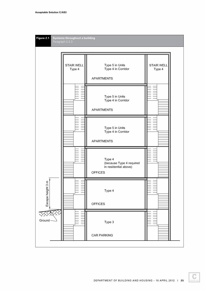
Figure 2.1 Systems throughout a building Paragraph 2.2.3
Acceptable Solution C/AS3
DEPARTMENT OF BUILDING AND HOUSING – 10 APRIL 2012 I 25

More than one risk group on a floor
2.2.4 If there is more than one risk group on one floor level, the fire safety requirements will depend on whether the risk groups occupy the same firecell, or whether the floor is divided by fire separations into different firecells.
Comment: Refer to Paragraphs 2.2.1 to 2.2.3 for the requirements for individual firecells in this risk group.
2.2.5 Where fire separations are not needed between different risk groups on the same floor level, the fire safety systems adopted for the whole floor level shall be those of the primary risk group (as defined in Paragraph 1.2.2).
2.2.6 The fire safety systems required by Paragraph 2.2.3 shall be interconnected to alert all occupants of that floor level in the event of fire.
Comment: Refer to Paragraphs 2.2.7 and 2.2.8 for the requirements for other floor levels in the building.
Table 2.1 Fire safety systems specified in this Acceptable Solution
Type of
system
System description Relevant Standards for installation
7 Automatic fire sprinkler system with smoke detection and alarm system
NZS 4541, NZS 4515, NZS 4512
9 Smoke control in air handling system AS/NZS 1668.1
18 Building fire hydrant system NZS 4510
Other floors in a building
2.2.7 The alarm systems required in a building shall be interconnected to alert all building occupants in the event of fire except:
a) In areas that have the local smoke component of a Type 5 system, and
b) In a risk group SI where it is deemed appropriate to alert management and staff without notifying other occupants.
Same risk group on different floors
2.2.8 If firecells containing the same risk group occur at different levels in the same building, the fire safety systems for the firecell having the most onerous requirements shall be applied to all firecells in that risk group.
2.2.9 THIS PARAGRAPH DELIBERATELY LEFT BLANK
2.2.10 THIS PARAGRAPH DELIBERATELY LEFT BLANK
Amend 2Dec 2013
Acceptable Solution C/AS3
26 I MINISTRY OF BUSINESS, INNOVATION AND EMPLOYMENT – 19 DECEMBER 2013

2.3. Fire resistance ratings
FRR values
2.3.1 Unless explicitly stated otherwise in this Acceptable Solution, the fire resistance ratings (FRRs) that apply for this risk group shall be as follows:
Life rating = 60 minutes. This applies to fire rating requirements in Part 3: Means of escape and Part 4: Control of internal fire and smoke spread.
Property rating = 60 minutes. This applies to fire rating requirements in Part 5: Control of external fire spread.
Comment: Throughout this Acceptable Solution, minimum FRRs are specified for particular situations. It is therefore essential to check for specific requirements.
Structural elements in a single storey building need not be fire rated if FRRs are not required for any other reason.
2.3.2 THIS PARAGRAPH DELIBERATELY LEFT BLANK
2.3.3 If there is more than one risk group on a floor in the building, the highest required FRR shall be applied to common spaces and shared escape routes for that floor level.
General requirements for FRRs
2.3.4 FRRs shall apply to the sides of primary and secondary elements which are exposed to fire.
2.3.5 When different FRRs apply on each side of a fire separation, being a wall, the higher rating shall apply to both sides.
2.3.6 Floors shall have an FRR for exposure from the underside.
2.3.7 The FRR of a primary element integral with a fire separation shall be no less than that of the fire separation.
2.3.8 Except as required by Paragraph 4.3.3, areas of external wall not permitted to be unprotected areas shall be rated for fire exposure from within a firecell.
2.3.9 Areas of external wall not permitted to be unprotected areas shall be rated for fire exposure from both sides equally where:
a) Walls are within 1.0 m of the relevant boundary, or
b) The building height is more than 10 m, or
c) The final exit is one or more floor levels below any risk group SI occupancy.
2.3.10 Building elements shall have an FRR no less than that of any building element to which they provide support within the firecell or in any adjacent firecell.
2.3.11 Structural framing members connected to building elements with an FRR shall be rated at no less than the building elements to which they are connected, or alternatively their connections and supports shall be designed so that their collapse during fire will not cause collapse of the fire rated elements.
Applying insulation component in FRR
2.3.12 THIS PARAGRAPH DELIBERATELY LEFT BLANK
2.3.13 Insulation ratings are not required in risk group SI.
Amend 2Dec 2013
Acceptable Solution C/AS3
MINISTRY OF BUSINESS, INNOVATION AND EMPLOYMENT – 19 DECEMBER 2013 I 27

Part 3: Means of escape
CONTENTS
3.1 General principles
3.2 Number of escape routes
3.3 Height and width of escape routes
3.4 Length of escape routes
3.5 Escape from basements
3.6 Open paths
3.7 Special cases of open paths
3.8 Dead ends
3.9 Exitways
3.10 Control of exitway activities
3.11 External escape routes
3.12 Deliberately left blank
3.13 Deliberately left blank
3.14 Deliberately left blank
3.15 Doors subdividing escape routes
3.16 Signs
3.1 General principles
3.1.1. All buildings shall have means of escape from fire which include escape routes. An escape route (see Figure 3.1) shall provide protection to any occupant escaping to a safe place from a fire within a building.
3.1.2. The components of an escape route, in ascending order of protection, are the open paths, exitways (these may comprise smoke lobbies and safe paths), and final exits (see Figure 3.1). Two or more of these components will be necessary, depending on the total travel distance. An escape route shall not pass from a higher to lower level of protection in the direction of escape.
3.1.3. Provided the allowable lengths of open paths are not exceeded, an escape route may comprise only an open path and final exit.
3.1.4. Escape routes shall comply with NZBC D1. Ramps, stairs, ladders, landings, handrails, doors, vision panels and openings shall comply with Acceptable Solution D1/AS1.
Acceptable Solution C/AS3
28 I DEPARTMENT OF BUILDING AND HOUSING – 10 APRIL 2012
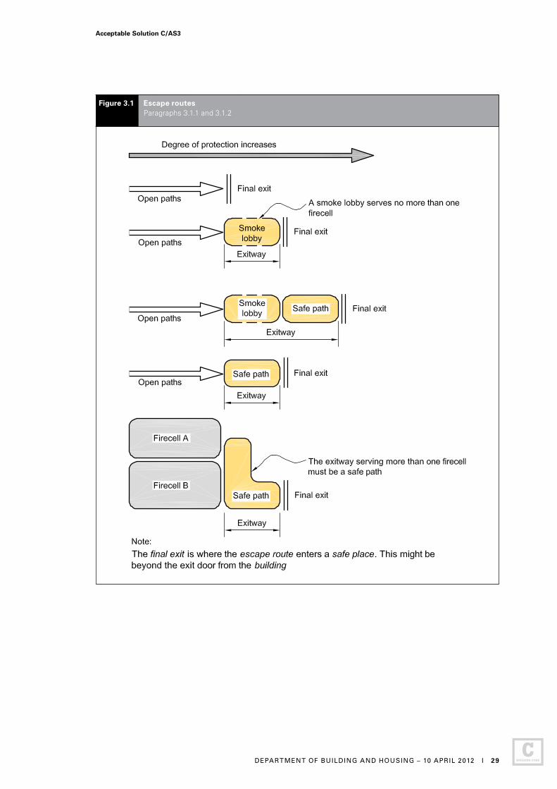
Figure 3.1 Escape routes Paragraphs 3.1.1 and 3.1.2
Acceptable Solution C/AS3
DEPARTMENT OF BUILDING AND HOUSING – 10 APRIL 2012 I 29
3.2 Number of escape routes
3.2.1 THIS PARAGRAPH DELIBERATELY LEFT BLANK
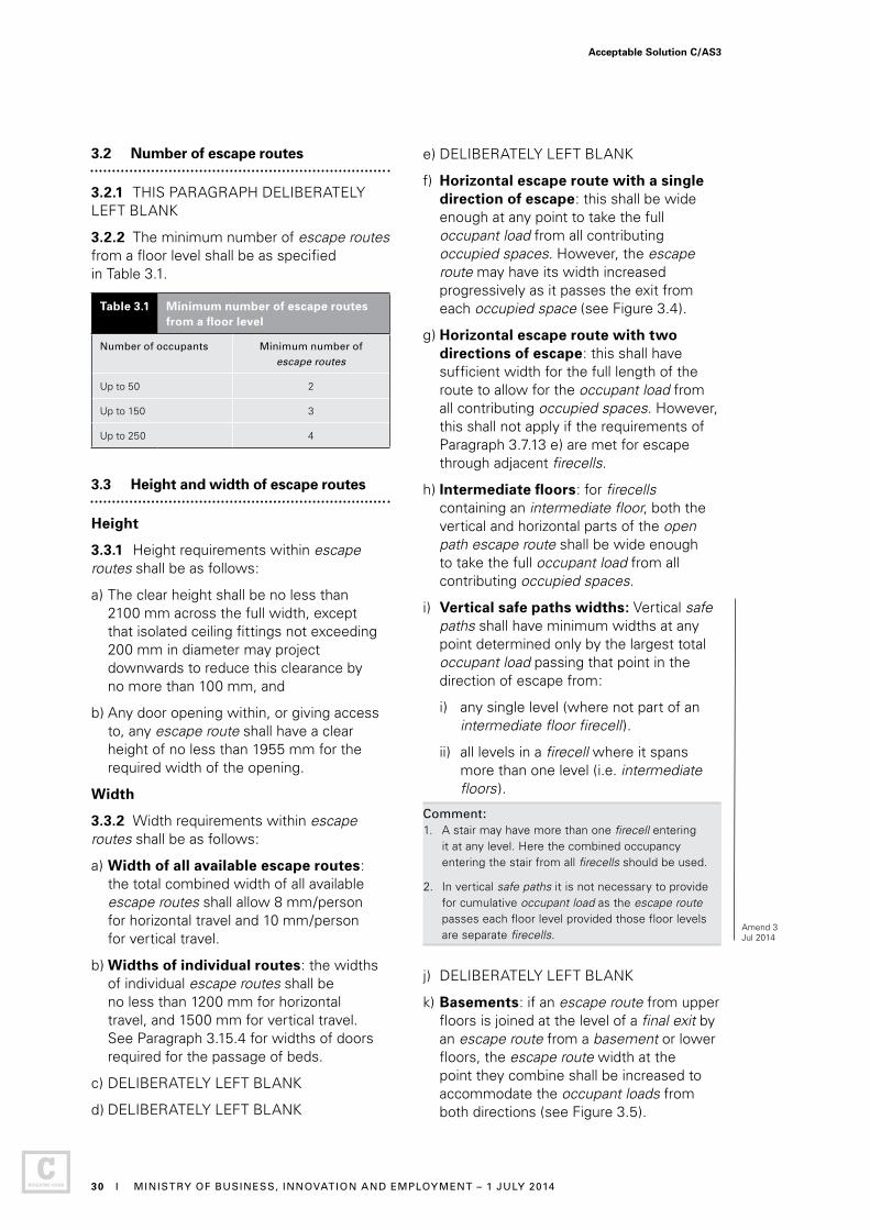
3.2.2 The minimum number of escape routes from a floor level shall be as specified in Table 3.1.
Table 3.1 Minimum number of escape routes from a floor level
Number of occupants Minimum number of
escape routes
Up to 50 2
Up to 150 3
Up to 250 4
3.3 Height and width of escape routes
Height
3.3.1 Height requirements within escape routes shall be as follows:
a) The clear height shall be no less than 2100 mm across the full width, except that isolated ceiling fittings not exceeding 200 mm in diameter may project downwards to reduce this clearance by no more than 100 mm, and
b) Any door opening within, or giving access to, any escape route shall have a clear height of no less than 1955 mm for the required width of the opening.
Width
3.3.2 Width requirements within escape routes shall be as follows:
a) Width of all available escape routes: the total combined width of all available escape routes shall allow 8 mm/person for horizontal travel and 10 mm/person for vertical travel.
b) Widths of individual routes: the widths of individual escape routes shall be no less than 1200 mm for horizontal travel, and 1500 mm for vertical travel. See Paragraph 3.15.4 for widths of doors required for the passage of beds.
c) DELIBERATELY LEFT BLANK
d) DELIBERATELY LEFT BLANK
e) DELIBERATELY LEFT BLANK
f) Horizontal escape route with a single direction of escape: this shall be wide enough at any point to take the full occupant load from all contributing occupied spaces. However, the escape route may have its width increased progressively as it passes the exit from each occupied space (see Figure 3.4).
g) Horizontal escape route with two directions of escape: this shall have sufficient width for the full length of the route to allow for the occupant load from all contributing occupied spaces. However, this shall not apply if the requirements of Paragraph 3.7.13 e) are met for escape through adjacent firecells.
h) Intermediate floors: for firecells containing an intermediate floor, both the vertical and horizontal parts of the open path escape route shall be wide enough to take the full occupant load from all contributing occupied spaces.
i) Vertical safe paths widths: Vertical safe paths shall have minimum widths at any point determined only by the largest total occupant load passing that point in the direction of escape from:
i) any single level (where not part of an intermediate floor firecell).
ii) all levels in a firecell where it spans more than one level (i.e. intermediate floors).
Comment:1. A stair may have more than one firecell entering
it at any level. Here the combined occupancy entering the stair from all firecells should be used.
2. In vertical safe paths it is not necessary to provide for cumulative occupant load as the escape route passes each floor level provided those floor levels are separate firecells.
j) DELIBERATELY LEFT BLANK
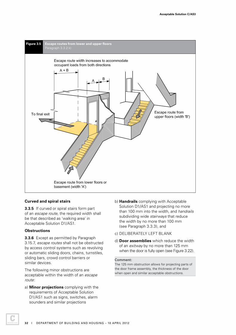
k) Basements: if an escape route from upper floors is joined at the level of a final exit by an escape route from a basement or lower floors, the escape route width at the point they combine shall be increased to accommodate the occupant loads from both directions (see Figure 3.5).
Acceptable Solution C/AS3
30 I MINISTRY OF BUSINESS, INNOVATION AND EMPLOYMENT – 1 JULY 2014
Amend 3Jul 2014

l) Ladders: the width requirements of Paragraph 3.3.2 b) do not apply to ladders where their use is permitted in this Acceptable Solution.
m) DELIBERATELY LEFT BLANK
Handrails and limitations to stairway widths
3.3.3 For safe evacuation on stairs, all stairways shall have at least one handrail. Furthermore:
a) Stairways in escape routes wider than 1500 mm shall have handrails on both sides, and
b) Stairways in escape routes wider than 2000 mm (see Figure 3.6) shall also be provided with intermediate handrails which are equally spaced and which provide a width not greater than 1500 mm for each section of the stairway.
Comment: Acceptable Solution D1/AS1 requires all stairways to have at least one handrail, and also requires accessible stairs to have handrails on both sides.
Figure 3.4 Increase in width for horizontal escape routes having a single direction of escape Paragraph 3.3.2 f)
3.3.4 If the escape height exceeds 35 m, no more than 1500 mm shall be credited to the width of any stairway when calculating stairyway capacity for an escape route.
Comment: While the stairway may be wider than 1500 mm, this is the maximum width that can be used for calculating stairway capacity. You may need to provide additional exitways to carry the occupant load.
Acceptable Solution C/AS3
DEPARTMENT OF BUILDING AND HOUSING – 10 APRIL 2012 I 31
Curved and spiral stairs
3.3.5 If curved or spiral stairs form part of an escape route, the required width shall be that described as ‘walking area’ in Acceptable Solution D1/AS1.
Obstructions
3.3.6 Except as permitted by Paragraph 3.15.7, escape routes shall not be obstructed by access control systems such as revolving or automatic sliding doors, chains, turnstiles, sliding bars, crowd control barriers or similar devices.
The following minor obstructions are acceptable within the width of an escape route:
a) Minor projections complying with the requirements of Acceptable Solution D1/AS1 such as signs, switches, alarm sounders and similar projections
b) Handrails complying with Acceptable Solution D1/AS1 and projecting no more than 100 mm into the width, and handrails subdividing wide stairways that reduce the width by no more than 100 mm (see Paragraph 3.3.3), and
c) DELIBERATELY LEFT BLANK
d) Door assemblies which reduce the width of an exitway by no more than 125 mm when the door is fully open (see Figure 3.22).
Comment: The 125 mm obstruction allows for projecting parts of the door frame assembly, the thickness of the door when open and similar acceptable obstructions.
Figure 3.5 Escape routes from lower and upper floors Paragraph 3.3.2 k)
Acceptable Solution C/AS3
32 I DEPARTMENT OF BUILDING AND HOUSING – 10 APRIL 2012

Figure 3.6 Limitations to stairway widths Paragraph 3.3.3 b)
3.4 Length of escape routes
3.4.1 An escape route may be any length, but:
a) The lengths of dead ends and total open paths shall not exceed the distances given in Table 3.2, adjusted as necessary for:
i) Reductions on intermediate floors (see Paragraph 3.4.3), and
ii) Reductions on stairs and ladders (see Paragraph 3.4.4), and
b) If the distance to the final exit exceeds the allowable length for the total open path, the remainder of the escape route shall be a safe path. (See Paragraph 3.9.7 for safe path length restrictions within a single floor level.)
Acceptable Solution C/AS3
DEPARTMENT OF BUILDING AND HOUSING – 10 APRIL 2012 I 33
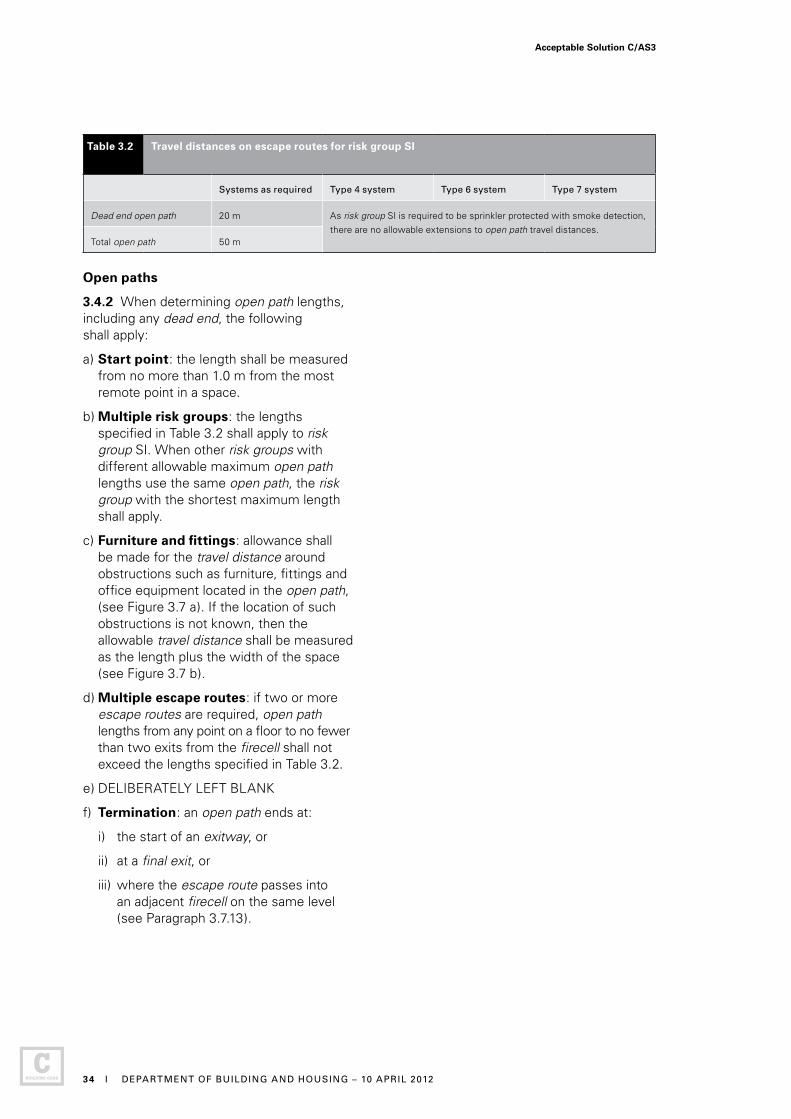
Table 3.2 Travel distances on escape routes for risk group SI
Systems as required Type 4 system Type 6 system Type 7 system
Dead end open path 20 m As risk group SI is required to be sprinkler protected with smoke detection, there are no allowable extensions to open path travel distances.
Total open path 50 m
Open paths
3.4.2 When determining open path lengths, including any dead end, the following shall apply:
a) Start point: the length shall be measured from no more than 1.0 m from the most remote point in a space.
b) Multiple risk groups: the lengths specified in Table 3.2 shall apply to risk group SI. When other risk groups with different allowable maximum open path lengths use the same open path, the risk group with the shortest maximum length shall apply.
c) Furniture and fittings: allowance shall be made for the travel distance around obstructions such as furniture, fittings and office equipment located in the open path, (see Figure 3.7 a). If the location of such obstructions is not known, then the allowable travel distance shall be measured as the length plus the width of the space (see Figure 3.7 b).
d) Multiple escape routes: if two or more escape routes are required, open path lengths from any point on a floor to no fewer than two exits from the firecell shall not exceed the lengths specified in Table 3.2.
e) DELIBERATELY LEFT BLANK
f) Termination: an open path ends at:
i) the start of an exitway, or
ii) at a final exit, or
iii) where the escape route passes into an adjacent firecell on the same level (see Paragraph 3.7.13).
Acceptable Solution C/AS3
34 I DEPARTMENT OF BUILDING AND HOUSING – 10 APRIL 2012
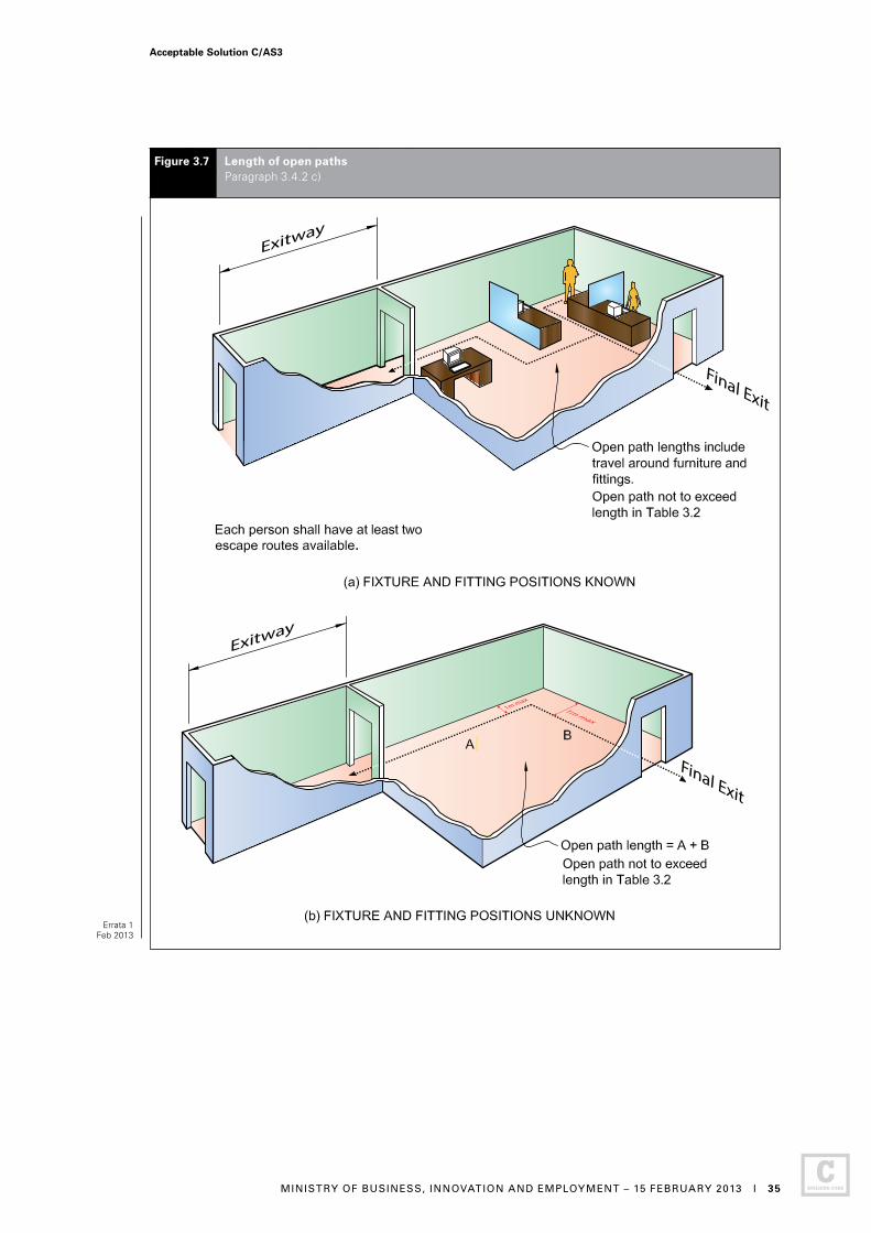
Final Exit
Final Exit
Figure 3.7 Length of open paths Paragraph 3.4.2 c)
.
Errata 1Feb 2013
Acceptable Solution C/AS3
MINISTRY OF BUSINESS, INNOVATION AND EMPLOYMENT – 15 FEBRUARY 2013 I 35
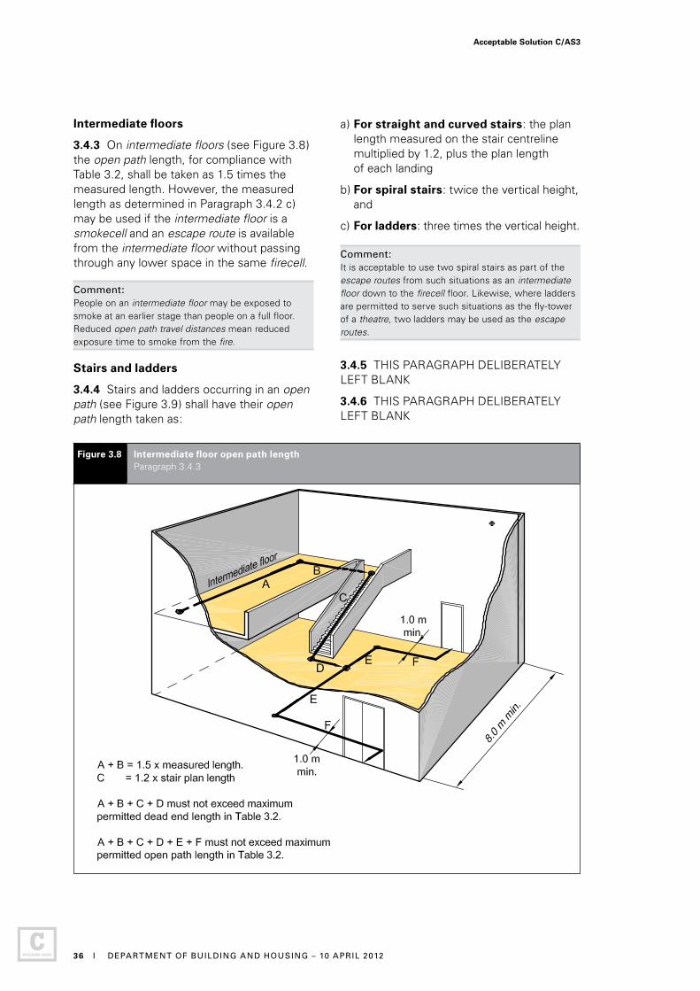
Intermediate floors
3.4.3 On intermediate floors (see Figure 3.8) the open path length, for compliance with Table 3.2, shall be taken as 1.5 times the measured length. However, the measured length as determined in Paragraph 3.4.2 c) may be used if the intermediate floor is a smokecell and an escape route is available from the intermediate floor without passing through any lower space in the same firecell.
Comment: People on an intermediate floor may be exposed to smoke at an earlier stage than people on a full floor. Reduced open path travel distances mean reduced exposure time to smoke from the fire.
Stairs and ladders
3.4.4 Stairs and ladders occurring in an open path (see Figure 3.9) shall have their open path length taken as:
Figure 3.8 Intermediate floor open path length Paragraph 3.4.3
a) For straight and curved stairs: the plan length measured on the stair centreline multiplied by 1.2, plus the plan length of each landing
b) For spiral stairs: twice the vertical height, and
c) For ladders: three times the vertical height. Comment: It is acceptable to use two spiral stairs as part of the escape routes from such situations as an intermediate floor down to the firecell floor. Likewise, where ladders are permitted to serve such situations as the fly-tower of a theatre, two ladders may be used as the escape routes.
3.4.5 THIS PARAGRAPH DELIBERATELY LEFT BLANK
3.4.6 THIS PARAGRAPH DELIBERATELY LEFT BLANK
Acceptable Solution C/AS3
36 I DEPARTMENT OF BUILDING AND HOUSING – 10 APRIL 2012

3.5 Escape from basements
3.5.1 Except where there are two or more escape routes serving only the basement firecells, and each terminates in a safe place, safe paths serving basement firecells shall be preceded by a smoke lobby, that shall have a plan area in accordance with Paragraph 3.9.2.
3.5.2 THIS PARAGRAPH DELIBERATELY LEFT BLANK
3.6 Open paths
Number and size
3.6.1 Open paths shall satisfy the specific requirements of Paragraphs 3.6.2 and 3.7 where they apply to a particular building.
Open path separation
3.6.2 If two or more open paths are required, they shall be separated from each other, and remain separated until reaching an exitway or final exit (see Figure 3.12). Separation shall be achieved by diverging (from the point where two escape routes are required), at an angle of no less than 90° until separated by:
a) A distance of at least 8.0 m, or
b) Smoke separations and smoke control doors.
Comment: If this separation or protection is not provided, the length of the open path is limited to that of a dead end. This is critical in planning single stairway buildings, as the stairway must be positioned within the dead end travel distance limits.
3.6.3 THIS PARAGRAPH DELIBERATELY LEFT BLANK
Figure 3.9 Stairs and ladders Paragraph 3.4.4
Acceptable Solution C/AS3
DEPARTMENT OF BUILDING AND HOUSING – 10 APRIL 2012 I 37
3.7 Special cases of open paths
Ramps
3.7.1 Where stairs are not used, changes in level on an escape route shall be formed as ramps and shall comply with Acceptable Solution D1/AS1.
3.7.2 THIS PARAGRAPH DELIBERATELY LEFT BLANK
3.7.3 THIS PARAGRAPH DELIBERATELY LEFT BLANK
Table 3.3: This table is not required for this Acceptable Solution.
3.7.4 THIS PARAGRAPH DELIBERATELY LEFT BLANK
3.7.5 THIS PARAGRAPH DELIBERATELY LEFT BLANK
3.7.6 THIS PARAGRAPH DELIBERATELY LEFT BLANK
3.7.7 THIS PARAGRAPH DELIBERATELY LEFT BLANK
3.7.8 THIS PARAGRAPH DELIBERATELY LEFT BLANK
3.7.9 THIS PARAGRAPH DELIBERATELY LEFT BLANK
3.7.10 THIS PARAGRAPH DELIBERATELY LEFT BLANK
3.7.11 THIS PARAGRAPH DELIBERATELY LEFT BLANK
3.7.12 THIS PARAGRAPH DELIBERATELY LEFT BLANK
Acceptable Solution C/AS3
38 I DEPARTMENT OF BUILDING AND HOUSING – 10 APRIL 2012
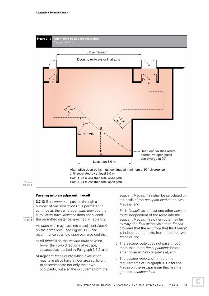
Passing into an adjacent firecell
3.7.13 If an open path passes through a number of fire separations it is permitted to continue as the same open path provided the cumulative travel distance does not exceed the permitted distance specified in Table 3.2.
An open path may pass into an adjacent firecell on the same level (see Figure 3.15) and recommence as a new open path provided that:
a) All firecells on the escape route have no fewer than two directions of escape, separated as required by Paragraph 3.6.2, and
b) Adjacent firecells into which evacuation may take place have a floor area sufficient to accommodate not only their own occupants, but also the occupants from the
adjacent firecell. This shall be calculated on the basis of the occupant load of the two firecells, and
c) Each firecell has at least one other escape route independent of the route into the adjacent firecell. This other route may be by way of a final exit or via a third firecell provided that the exit from that third firecell is independent of exits from the other two firecells, and
d) The escape route does not pass through more than three fire separations before entering an exitway or final exit, and
e) The escape route width meets the requirements of Paragraph 3.3.2 for the firecell on the escape route that has the greatest occupant load.
Figure 3.12 Alternative open path separation Paragraph 3.6.2
Errata 1Feb 2013
Acceptable Solution C/AS3
MINISTRY OF BUSINESS, INNOVATION AND EMPLOYMENT – 1 JULY 2014 I 39
Amend 3Jul 2014

Comment:Open path lengths in each firecell are controlled by the requirements of Table 3.2 for that firecell.
Refer to Paragraph 3.15.3 to determine whether doors between firecells need to be hung to swing both ways because escape may be in either direction, and Paragraph 3.15.9 for hold-open device requirements.
This provision may be used to divide wards in hospitals and similar institutions where occupants are bedridden, and provision is made for beds to be wheeled through into a ‘holding area’. See Paragraph 4.6.3.
3.7.14 THIS PARAGRAPH DELIBERATELY LEFT BLANK
3.8 Dead ends
No more than 50 occupants
3.8.1 A dead end shall not serve an occupant load greater than 50.
3.8.2 THIS PARAGRAPH DELIBERATELY LEFT BLANK
3.9 Exitways
3.9.1 Exitways consist of smoke lobbies and safe paths.
Comment:Smoke lobbies are not required in risk group SI.
Figure 3.15 Open path passing into adjacent firecells Paragraphs 3.7.13 and 4.16.9
Acceptable Solution C/AS3
40 I DEPARTMENT OF BUILDING AND HOUSING – 10 APRIL 2012
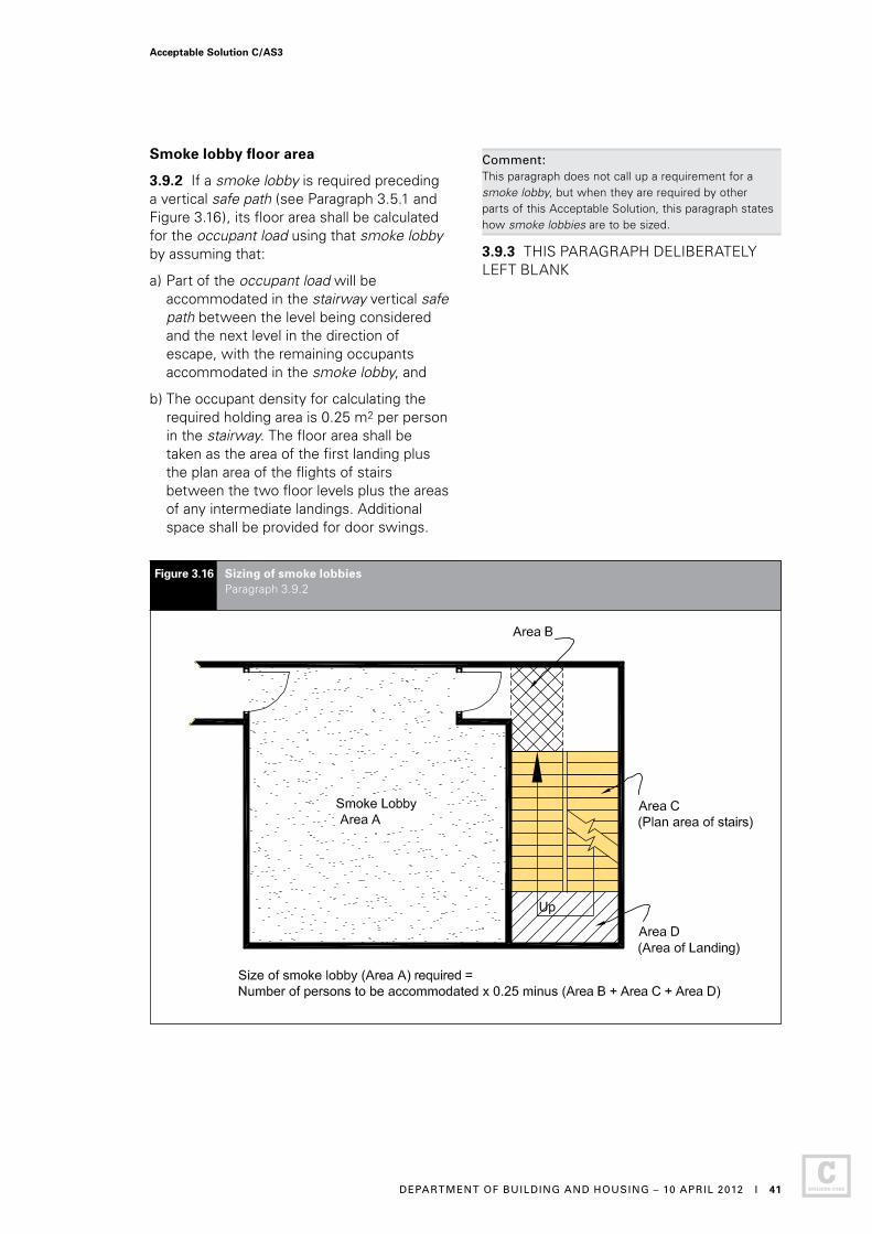
Smoke lobby floor area
3.9.2 If a smoke lobby is required preceding a vertical safe path (see Paragraph 3.5.1 and Figure 3.16), its floor area shall be calculated for the occupant load using that smoke lobby by assuming that:
a) Part of the occupant load will be accommodated in the stairway vertical safe path between the level being considered and the next level in the direction of escape, with the remaining occupants accommodated in the smoke lobby, and
b) The occupant density for calculating the required holding area is 0.25 m2 per person in the stairway. The floor area shall be taken as the area of the first landing plus the plan area of the flights of stairs between the two floor levels plus the areas of any intermediate landings. Additional space shall be provided for door swings.
Figure 3.16 Sizing of smoke lobbies Paragraph 3.9.2
Comment: This paragraph does not call up a requirement for a smoke lobby, but when they are required by other parts of this Acceptable Solution, this paragraph states how smoke lobbies are to be sized.
3.9.3 THIS PARAGRAPH DELIBERATELY LEFT BLANK
Acceptable Solution C/AS3
DEPARTMENT OF BUILDING AND HOUSING – 10 APRIL 2012 I 41
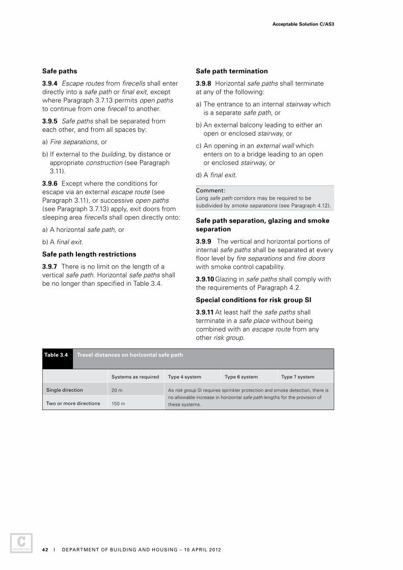
Safe paths
3.9.4 Escape routes from firecells shall enter directly into a safe path or final exit, except where Paragraph 3.7.13 permits open paths to continue from one firecell to another.
3.9.5 Safe paths shall be separated from each other, and from all spaces by:
a) Fire separations, or
b) If external to the building, by distance or appropriate construction (see Paragraph 3.11).
3.9.6 Except where the conditions for escape via an external escape route (see Paragraph 3.11), or successive open paths (see Paragraph 3.7.13) apply, exit doors from sleeping area firecells shall open directly onto:
a) A horizontal safe path, or
b) A final exit.
Safe path length restrictions
3.9.7 There is no limit on the length of a vertical safe path. Horizontal safe paths shall be no longer than specified in Table 3.4.
Safe path termination
3.9.8 Horizontal safe paths shall terminate at any of the following:
a) The entrance to an internal stairway which is a separate safe path, or
b) An external balcony leading to either an open or enclosed stairway, or
c) An opening in an external wall which enters on to a bridge leading to an open or enclosed stairway, or
d) A final exit.
Comment: Long safe path corridors may be required to be subdivided by smoke separations (see Paragraph 4.12).
Safe path separation, glazing and smoke separation
3.9.9 The vertical and horizontal portions of internal safe paths shall be separated at every floor level by fire separations and fire doors with smoke control capability.
3.9.10 Glazing in safe paths shall comply with the requirements of Paragraph 4.2.
Special conditions for risk group SI
3.9.11 At least half the safe paths shall terminate in a safe place without being combined with an escape route from any other risk group.
Table 3.4 Travel distances on horizontal safe path
Systems as required Type 4 system Type 6 system Type 7 system
Single direction 20 m As risk group SI requires sprinkler protection and smoke detection, there is no allowable increase in horizontal safe path lengths for the provision of these systems.Two or more directions 150 m
Acceptable Solution C/AS3
42 I DEPARTMENT OF BUILDING AND HOUSING – 10 APRIL 2012
3.10 Control of exitway activities
3.10.1 Exitways shall not be used for:
a) Any storage of goods, solid waste or solid waste containers, or
b) Entry points to solid waste chutes, or
c) The location of furniture or other combustibles, or
d) Storage of cloaks or linen, or
e) A cleaner’s cupboard not fire separated from the exitway, or
f) The location of an electrical switchboard or similar, or
g) Any activity (other than as permitted by Paragraph 3.10.2).
3.10.2 Some activities are permitted in an exitway if:
a) An alternative escape route is available from all firecells served by the safe path in which the activities occur, and
b) DELIBERATELY LEFT BLANK
c) The escape route is not impeded by the activity or the occupants involved in that activity, and
d) Those activities:
i) are visible to users of the exitway, except in the case of sanitary fixtures
ii) exist only to provide support functions to the activities of the risk group served by the exitway
iii) occupy a total floor area of not more than 6.0 m2.
Comment: Permitted activities include but are not limited to a reception counter (but not an associated office) and toilet facilities
Lifts
3.10.3 A passenger lift, but not a goods lift, may be located in a vertical safe path containing a stairway provided the following conditions are satisfied:
a) The lift shaft and all its openings are located entirely within a single firecell containing the vertical safe path, and
b) Passenger access into and from the lift takes place entirely within the safe path, and
c) No other activity occurs within the vertical safe path, and
d) The lift machine room is a separate firecell, and the openings for lift ropes through the fire separation are as small as practicable, and any penetrations, such as for electrical cables, are fire stopped. (See Paragraph 4.4 for fire stopping.)
3.10.4 Lift doors shall be as specified in Paragraphs 4.16.3 and 4.16.11.
3.10.5 THIS PARAGRAPH DELIBERATELY LEFT BLANK
3.11 External escape routes
3.11.1 If an escape route enters a space exposed to the open air (e.g. an open stairway, a balcony, across a roof or a ground level path), it shall meet the requirements of a safe path between that point and the final exit. Safe path separation requirements shall be achieved by providing either distance or fire rated construction between the escape route and adjacent firecells, as specified in Paragraphs 3.11.2 to 3.11.6.
Comment: Balconies with one direction of escape comply with the requirements of a safe path if the external wall beside the balcony has no unprotected areas or if the balcony is large enough to allow separation by distance from the external wall (see Paragraph 3.11.2). Balconies with two directions of escape from all firecell exits are also considered to be safe paths, even if the adjacent external wall has 100% unprotected area.
Separation by distance
3.11.2 Separation by distance shall be achieved by:
a) Locating the escape route no less than 1.0 m from external walls, or
b) Locating the escape route so that it diverges from external walls (see Paragraph 3.11.5 a), or
c) Providing alternative directions of escape from the point where the escape route passes through an external wall and becomes an external escape route (see Paragraph 3.11.5 b).
Amend 3Jul 2014
Acceptable Solution C/AS3
DEPARTMENT OF BUILDING AND HOUSING – 10 APRIL 2012 I 43
Amend 3Jul 2014
Amend 3Jul 2014
Amend 3Jul 2014
3.11.3 If there is only one direction of escape, roofs and external walls shall have no unprotected areas closer than 1.0 m to an external escape route as all firecells passed by the external escape route are sprinklered.
Comment: This provision is to limit heat radiation exposure to occupants who have only one direction of escape. Therefore, the limiting distances apply horizontally to both sides of the escape route.
3.11.4 If the distance separating external walls or roofs from an external dead end escape route is less than 1.0 m, those walls and roofs shall comply with the FRR requirements of Paragraphs 5.3 and 5.7.3 to 5.7.5. Glazing shall comply with Paragraph 4.2 and the FRR shall be in accordance with Paragraph 2.3.
3.11.5 For an escape route which passes through an opening in an external wall, parts of the external wall need not be fire rated if:
a) The direction of escape to a single final exit diverges from the external wall at an angle of no less than 45° in plan, or
b) The directions of escape to alternative final exits diverge from each other at an angle of no less than 90° in plan and the escape routes subsequently do not both pass the same firecell (other than the firecell from which they originated).
c) DELIBERATELY LEFT BLANK
d) DELIBERATELY LEFT BLANK
Comment: The relaxation of FRR requirements does not apply where fire rated construction is necessary due to the proximity of a relevant boundary (see Paragraph 5.3).
Separation by fire rated construction
3.11.6 Except where the separation distance requirements of Paragraphs 3.11.3 or 3.11.5 are achieved:
a) External walls and roofs adjacent to external escape routes shall comply with the FRR requirements of Paragraphs 5.3 and 5.7 and have no unprotected areas, except that glazing for safe paths complying with Paragraph 4.2 shall be permitted, and
b) If the escape route is a balcony with a single direction of escape, and the vertical distance between the underside of the balcony and the closest unprotected area in the external wall below is less than 5.0 m (see Figure 3.19), balcony barriers shall:
i) have no openings, and
ii) be protected with a material having a Group Number of 1
Comment: See Verification Method C/VM2 Appendix A for the method of assigning the Group Number.
c) If the vertical separation between the underside of an external escape route and unprotected areas in the external wall below is less than 5.0 m:
i) the floor of any external escape route closer than 2.0 m to an external wall shall have an FRR of no less than 60/60/60, except that this does not apply if the escape route is a balcony with two directions of escape, and
ii) treads and risers of stairs on external escape routes shall either be constructed from a material with a critical radiant flux of no less than 2.2 kW/m2 or shall be protected on the underside with a material having a Group Number of no greater than 2, and
Comment: If the escape route is a balcony with two directions of escape, the external wall need not be a fire separation and the requirements for the barrier b) and the floor of the balcony c) i) do not apply.
d) If the escape route comprises external horizontal and internal vertical safe paths, a smoke separation shall be provided between them.
Acceptable Solution C/AS3
44 I MINISTRY OF BUSINESS, INNOVATION AND EMPLOYMENT – 1 JULY 2014
Amend 3Jul 2014
Amend 3Jul 2014

Figure 3.19 Open balconies Paragraphs 3.11.6 and 3.11.7
Acceptable Solution C/AS3
DEPARTMENT OF BUILDING AND HOUSING – 10 APRIL 2012 I 45
Ventilation openings
3.11.7 The open area of a balcony or bridge shall be no less than 50% of the balcony floor area, and shall be evenly distributed along the open sides and any approach ramp (see Figure 3.19). Where an escape route on a balcony is served by an open stairway, similar ventilation shall be provided on the stairway. Open sides shall not be enclosed above a height of 1100 mm from the floor, except that a fixed open grille may be used if it provides the required free air space.
Barriers
3.11.8 Changes in exitway floor level other than in the direction of travel shall have barriers that comply with Acceptable Solution F4/AS1.
3.11.9 THIS PARAGRAPH DELIBERATELY LEFT BLANK
3.11.10 THIS PARAGRAPH DELIBERATELY LEFT BLANK
3.12 THIS PARAGRAPH DELIBERATELY LEFT BLANK
3.13 THIS PARAGRAPH DELIBERATELY LEFT BLANK
3.14 THIS PARAGRAPH DELIBERATELY LEFT BLANK
3.15 Doors subdividing escape routes
Door closers and latching
3.15.1 Except as permitted by Paragraph 3.15.7 (revolving doors, automatic doors and access control systems), doors on escape routes shall satisfy the following requirements:
a) They shall be hinged or pivoted on one vertical edge only, except that sliding doors may be used where the space, including an exitway, has an occupant load of less than 20. Roller shutter doors or tilt doors shall not be used as escape route width except in an intermittently occupied space where the roller shutter door is the only access route and is open at all times the space is occupied, and
b) Fire and smoke control doors shall be self-closing, and the self-closing device shall either be:
i) active at all times, or
ii) activated by releasing a hold-open device in response to operation of a smoke detector (see Paragraph 3.15.10), or
iii) a self-closer that is activated by operation of a smoke detector but allows the door to swing freely at other times. The smoke detector requirements shall be the same as for a hold-open device (see Paragraph 3.15.10), and
c) If such doors are required to be secure, they shall be fitted with simple fastenings that can be readily operated from the direction approached by people making an escape complying with Paragraph 3.15.14, and
d) They shall not be fitted with any locking devices unless these comply with Paragraph 3.15.2, and
e) They shall have door handles which satisfy the requirements of Acceptable Solution D1/AS1 for use by people with disabilities, and
f) They shall be constructed to ensure that the forces required to open these doors do not exceed those able to be applied:
i) with a single hand to release the latch (where fitted), and
ii) using two hands to set the door in motion, and
iii) using a single hand to open the door to the minimum required width.
Comment: These requrements are based on the force requirements of Appendix C C6.1.3.
Locking devices
3.15.2 If the building is occupied, locking devices shall:
a) Be clearly visible, located where such a device would be normally expected and, in the event of fire, designed to be easily operated without a key or other security device, and allow the door to open in the normal manner.
Acceptable Solution C/AS3
46 I DEPARTMENT OF BUILDING AND HOUSING – 10 APRIL 2012
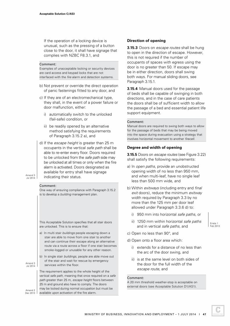
If the operation of a locking device is unusual, such as the pressing of a button close to the door, it shall have signage that complies with NZBC F8.3.1, and
Comment: Examples of unacceptable locking or security devices are card access and keypad locks that are not interfaced with the fire alarm and detection systems.
b) Not prevent or override the direct operation of panic fastenings fitted to any door, and
c) If they are of an electromechanical type, they shall, in the event of a power failure or door malfunction, either:
i) automatically switch to the unlocked (fail-safe) condition, or
ii) be readily opened by an alternative method satisfying the requirements of Paragraph 3.15.2 a), and
d) If the escape height is greater than 25 m occupants in the vertical safe path shall be able to re-enter every floor. Doors required to be unlocked from the safe path side may be unlocked at all times or only when the fire alarm is activated. Doors designated as available for entry shall have signage indicating their status.
Comment:One way of ensuring compliance with Paragraph 3.15.2 is to develop a building management plan.
This Acceptable Solution specifies that all stair doors are unlocked. This is to ensure that:
a) In multi stair buildings people escaping down a stair are able to move from one stair to another and can continue their escape along an alternative route via a route across a floor if one stair becomes smoke-logged or unusable for any other reason.
b) In single stair buildings, people are able move out of the stair and wait for rescue by emergency services within the floor.
The requirement applies to the whole height of the vertical safe path, meaning that once required on a safe path greater than 25 m, escape height floors between 25 m and ground also have to comply. The doors may be locked during normal occupation but must be available upon activation of the fire alarm.
Direction of opening
3.15.3 Doors on escape routes shall be hung to open in the direction of escape. However, this is not required if the number of occupants of spaces with egress using the door is no greater than 50. If escape may be in either direction, doors shall swing both ways. For manual sliding doors, see Paragraph 3.15.1.
3.15.4 Manual doors used for the passage of beds shall be capable of swinging in both directions, and in the case of care patients the doors shall be of sufficient width to allow the passage of a bed and essential patient life support equipment.
Comment: Manual doors are required to swing both ways to allow for the passage of beds that may be being moved into the space during evacuation using a strategy that involves horizontal movement to another firecell.
Degree and width of opening
3.15.5 Doors on escape routes (see Figure 3.22) shall satisfy the following requirements:
a) In open paths, provide an unobstructed opening width of no less than 950 mm, and when multi-leaf, have no single leaf less than 500 mm wide, and
b) Within exitways (including entry and final exit doors), reduce the minimum exitway width required by Paragraph 3.3 by no more than the 125 mm per door leaf allowed under Paragraph 3.3.6 d) to:
i) 950 mm into horizontal safe paths, or
ii) 1250 mm within horizontal safe paths and in vertical safe paths, and
c) Open no less than 90°, and
d) Open onto a floor area which:
i) extends for a distance of no less than the arc of the door swing, and
ii) is at the same level on both sides of the door for the full width of the escape route, and
Comment: A 20 mm threshold weather-stop is acceptable on external doors (see Acceptable Solution D1/AS1).
Errata 1Feb 2013
Amend 2Dec 2013
Amend 3Jul 2014
Acceptable Solution C/AS3
MINISTRY OF BUSINESS, INNOVATION AND EMPLOYMENT – 1 JULY 2014 I 47
Amend 3Jul 2014
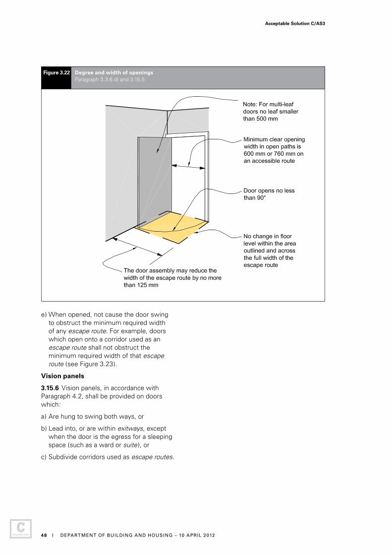
Figure 3.22 Degree and width of openings Paragraph 3.3.6 d) and 3.15.5
e) When opened, not cause the door swing to obstruct the minimum required width of any escape route. For example, doors which open onto a corridor used as an escape route shall not obstruct the minimum required width of that escape route (see Figure 3.23).
Vision panels
3.15.6 Vision panels, in accordance with Paragraph 4.2, shall be provided on doors which:
a) Are hung to swing both ways, or
b) Lead into, or are within exitways, except when the door is the egress for a sleeping space (such as a ward or suite), or
c) Subdivide corridors used as escape routes.
Acceptable Solution C/AS3
48 I DEPARTMENT OF BUILDING AND HOUSING – 10 APRIL 2012
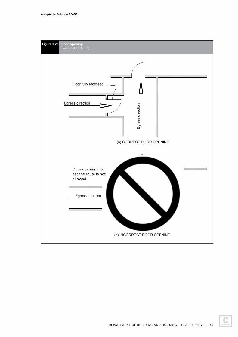
Figure 3.23 Door opening Paragraph 3.15.5 e)
Door opening into escape route is not allowed
Acceptable Solution C/AS3
DEPARTMENT OF BUILDING AND HOUSING – 10 APRIL 2012 I 49
Revolving doors, automatic doors and access control systems
3.15.7 Revolving doors (see Figure 3.24 a)), automatic doors (of all types) and access control systems shall:
a) Not be allowed across an escape route at any point leading into or within an exitway, but
b) Be allowed in an open path or at a final exit, provided that in the event of a power failure or malfunction, the doors or access control systems continue to provide a safe means of escape from fire without reducing the required width by:
i) automatically opening and remaining open, or
ii) being readily pushed to the outward open position by the building occupants in an emergency (refer to Figure 3.24 (b)).
Comment: Access control systems may be in the form of turnstiles or entrance gates, in both horizontal and vertical planes. These are usually found in shopping centres, entertainment venues and similar occupancies.
The requirements in ii) are based on the force requirements in Appendix C C6.1.3.
3.15.8 Paragraph 3.15.7 b) need not apply if alternative swing doors of the required width are provided immediately adjacent to the revolving or sliding doors.
See Paragraph 3.16 for signage requirements.
Hold-open devices
3.15.9 Detector-activated hold-open devices shall be fitted to all fire doors or smoke control doors required:
a) Between open paths and exitways if the occupant load is greater than 1000, and
b) For subdividing long corridors (see Paragraph 4.12), and
c) In fire separations where an escape route passes into an adjacent firecell (see Paragraph 3.7.13), and
Comment: An example of c) would be between a horizontal safe path or smoke lobby and a vertical safe path.
d) In locations where, due to the type or volume of occupant traffic using the doors, the doors may be kept open by unauthorised means.
Comment:Hold-open devices are used where it is not practical to assume that fire doors and smoke control doors will remain closed because of the type or volume of occupant traffic using these doors. The devices should eliminate the unsafe practice of wedging or otherwise keeping self-closing doors open.
For the convenience of building occupants, it is often useful to provide a clearly-labelled push-button release adjacent to doors with hold-open devices.
3.15.10 Detectors for releasing hold-open devices shall be smoke detectors which are:
a) Integral with the hold-open device and comply with Appendix C, or
b) Located on the ceiling adjacent to the doorset on both sides of the doorset, or
c) Part of an automatic smoke detection system on both sides of the doorset.
Delayed action unlocking devices
3.15.11 Delayed action unlocking devices on escape routes shall be installed only if:
a) The firecell is protected by a Type 4 or Type 7 system, and
b) Fire alarm activation instantly overrides any delay, and
c) The delay in operation does not exceed 15 seconds, and
d) Signage warning of the delay in operation and complying with NZBC F8.3.1 is provided.
Comment: A delayed action unlocking device is a security mechanism that allows a door to be unlocked without the use of a key, but does not release the door under non-emergency conditions until after a time delay has elapsed. The time delay allows the person intending to use the door to be checked for security reasons.
Acceptable Solution C/AS3
50 I DEPARTMENT OF BUILDING AND HOUSING – 10 APRIL 2012
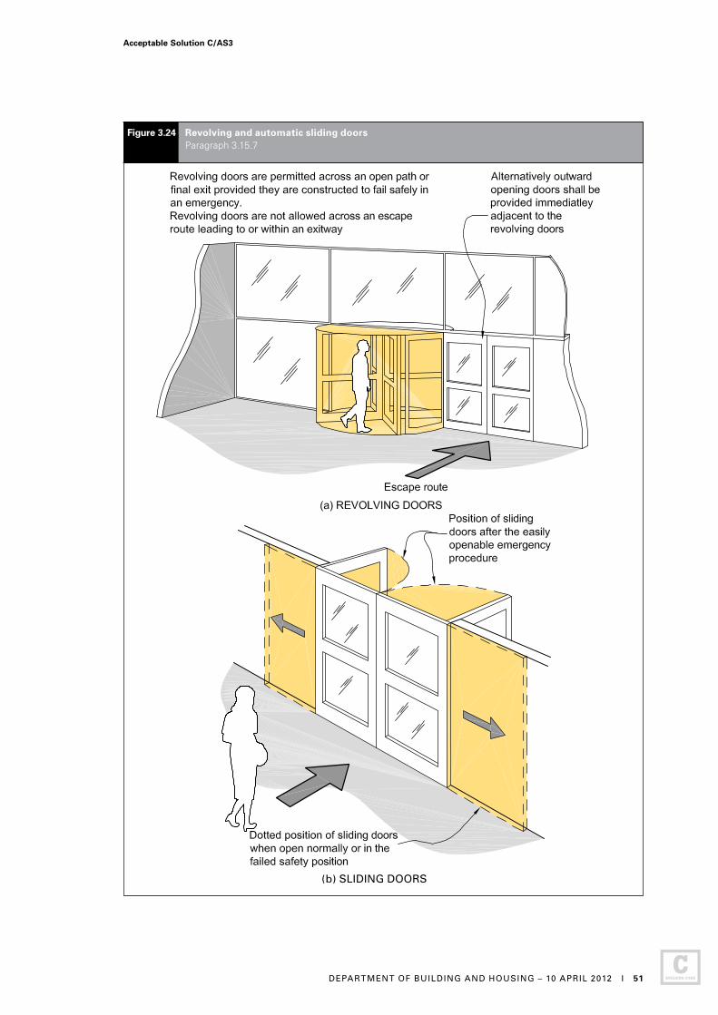
Figure 3.24 Revolving and automatic sliding doors Paragraph 3.15.7
(b) SLIDING DOORS
Acceptable Solution C/AS3
DEPARTMENT OF BUILDING AND HOUSING – 10 APRIL 2012 I 51
3.15.12 THIS PARAGRAPH DELIBERATELY LEFT BLANK
3.15.13 THIS PARAGRAPH DELIBERATELY LEFT BLANK
Simple fastenings
3.15.14 Doors on escape routes (whether or not the doors are fire doors) shall be fitted with simple fastenings that can be easily operated from the direction from which people approach when making their escape.
Comment:This generally excludes the use of keyed locks and bolt fastenings, see Paragraph 3.15.2 for security and safety.
3.16 Signs
3.16.1 All escape routes, fire doors and smoke control doors shall have signs complying with NZBC F8.
Acceptable Solution C/AS3
52 I DEPARTMENT OF BUILDING AND HOUSING – 10 APRIL 2012
Part 4: Control of internal fire and smoke spread
CONTENTS
4.1 Firecells
4.2 Glazing in fire and smoke separations
4.3 Structural stability during fire
4.4 Fire stopping
4.5 Firecell construction
4.6 Specific requirements for sleeping areas
4.7 Deliberately left blank
4.8 Deliberately left blank
4.9 Exitways
4.10 Intermittent activities
4.11 Protected shafts
4.12 Long corridor subdivision
4.13 Floors
4.14 Subfloor spaces
4.15 Concealed spaces
4.16 Closures in fire and smoke separations
4.17 Interior surface finishes, floor coverings and suspended flexible fabrics
4.18 Building services plant
4.1 Firecells
4.1.1 Firecells shall be fire separated from each other by the life rating specified in Paragraph 2.3 of this Acceptable Solution if the firecell is categorised in risk group SI or by the higher of the two life ratings if it is categorised in another risk group (see Paragraph 2.3 of the relevant Acceptable Solution to determine that life rating ).
4.2 Glazing in fire and smoke separations
4.2.1 Glazing in fire separations shall be fixed fire resisting glazing having the same FRR value for integrity as the fire separation.
4.2.2 THIS PARAGRAPH DELIBERATELY LEFT BLANK
4.2.3 There is no restriction on the area of glazing in smoke separations (including smoke lobbies). Non-fire resisting glazing may be used if it is toughened or laminated safety glass. Glazing shall have at least the same smoke-stopping ability as the smoke separation.
Fire doors and smoke control doors
4.2.4 Glazing in fire doors shall be fire resisting glazing having the same integrity value as the door. If vision panels are used they shall comply with NZS 4520.
4.2.5 Glazing in smoke control doors shall meet the requirements for smoke separations.
Amend 3Jul 2014
Acceptable Solution C/AS3
MINISTRY OF BUSINESS, INNOVATION AND EMPLOYMENT – 1 JULY 2014 I 53
4.3 Structural stability during fire
Stability of building elements having an FRR
4.3.1 To avoid premature failure, this Acceptable Solution requires the structural stability of primary building elements with an FRR to be retained for the duration of that FRR. Primary elements, located entirely within a firecell and providing support to fire separations, may need to be evaluated for fire exposure from multiple sides simultaneously.
Comment: This situation arises when a primary element, such as a column or wall, located entirely within a firecell provides lateral support to a firecell boundary wall or vertical support to the firecell floor/ceiling. Results against the standard furnace test for fire resistance may not be a suitable as they commonly relate to exposure from one side only. Separate evaluation is required to assess the performance of primary elements when exposed to fire from more relevant sides simultaneously.
4.3.2 During a fire, primary elements shall resist collapse under:
a) The design dead and live loads required by NZBC B1, and
b) Any additional loads caused by the fire.
Comment:NZBC B1.3.3 (c) and (i) requires that structural stability take account of vertical and horizontal loads, temperature and fire effects.
Additional loadings can arise from changes in length or other deformations in building elements as a result of high temperatures.
Yield strength of most materials generally reduces with temperature increase, so that strength reduction is related to the time for which the primary element is exposed to fire. Factors which need to be taken into account include the maximum temperature attained, the capacity of the element to absorb heat, potential loss of section, the degree of exposure, whether any applied coating is used to protect the element from the effects of fire, and the degree of restraint provided by the surrounding structure.
Unrated primary elements
4.3.3 In many cases primary elements are rated for structural adequacy, and sometimes for integrity and insulation. However, primary elements need not have an FRR where any of the following circumstances exist:
a) They are located outside an external wall which is 2.0 m or more from the relevant boundary, and are shielded from the effects of fire by protected areas of the wall (see Figure 4.1)
b) They are added to strengthen an existing building and are required only to carry horizontal loads induced by wind or earthquake.
Acceptable Solution C/AS3
54 I DEPARTMENT OF BUILDING AND HOUSING – 10 APRIL 2012
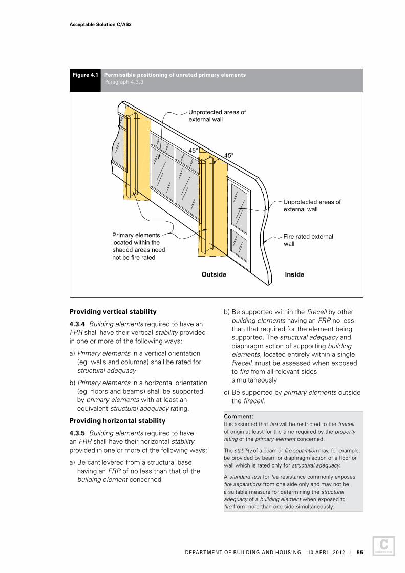
Figure 4.1 Permissible positioning of unrated primary elements Paragraph 4.3.3
Providing vertical stability
4.3.4 Building elements required to have an FRR shall have their vertical stability provided in one or more of the following ways:
a) Primary elements in a vertical orientation (eg, walls and columns) shall be rated for structural adequacy
b) Primary elements in a horizontal orientation (eg, floors and beams) shall be supported by primary elements with at least an equivalent structural adequacy rating.
Providing horizontal stability
4.3.5 Building elements required to have an FRR shall have their horizontal stability provided in one or more of the following ways:
a) Be cantilevered from a structural base having an FRR of no less than that of the building element concerned
b) Be supported within the firecell by other building elements having an FRR no less than that required for the element being supported. The structural adequacy and diaphragm action of supporting building elements, located entirely within a single firecell, must be assessed when exposed to fire from all relevant sides simultaneously
c) Be supported by primary elements outside the firecell.
Comment:It is assumed that fire will be restricted to the firecell of origin at least for the time required by the property rating of the primary element concerned.
The stability of a beam or fire separation may, for example, be provided by beam or diaphragm action of a floor or wall which is rated only for structural adequacy.
A standard test for fire resistance commonly exposes fire separations from one side only and may not be a suitable measure for determining the structural adequacy of a building element when exposed to fire from more than one side simultaneously.
Acceptable Solution C/AS3
DEPARTMENT OF BUILDING AND HOUSING – 10 APRIL 2012 I 55
4.4 Fire stopping
Introduction
4.4.1 The continuity and effectiveness of fire separations shall be maintained around penetrations, and in gaps between or within building elements, by the use of fire stops.
Fire stops
4.4.2 Fire stops shall have an FRR of no less than that required for the fire separation within which they are installed, and shall be tested in accordance with Appendix C C5.1.
4.4.3 Fire stops and methods of installation shall be identical to those of the prototype used in tests to establish their FRR.
4.4.4 The material selected for use as fire stops shall have been tested for the type and size of the gap or penetration, and for the type of material and construction used in the fire separation.
Comment: There are many types of fire stops (eg, mastics, collars, pillows), each designed to suit specific situations. A fire stop is appropriate for a particular application if it passes the test criteria when installed as proposed.
4.4.5 A fire stop for a penetration is not required to have an insulation rating if means are provided to keep combustible materials at a distance of 300 mm away from the penetration and the fire stop to prevent ignition.
4.5 Firecell construction
4.5.1 Each of the building elements enclosing a firecell is permitted to have a different FRR depending on the characteristics of the firecell, the reason for the FRR, and the risk groups contained on either side of any fire separation.
Comment:An FRR of zero may apply to some walls and most roofs.
4.5.2 Except where intermediate floors are permitted, each floor in a multi-storey building shall be a fire separation.
4.5.3 Fire and smoke separations shall have no openings other than:
a) For closures such as doorsets, and
b) Penetrations complying with Paragraph 4.4, and
c) For glazing permitted by Paragraph 4.2.
4.5.4 Firecell and smokecell effectiveness shall be maintained by ensuring continuity of fire and smoke separations at separation junctions, and around joints where closures, protected shafts and penetrations occur.
Junctions of fire separations
4.5.5 Where fire separations meet other fire separations or fire rated parts of external walls, they shall either be bonded together or have the junction fire stopped over its full length (see Figures 4.2 and 4.3).
4.5.6 Where one fire separation is a wall and the other a floor, the wall/floor junction shall be constructed with the FRR required for the higher rated element.
Junctions with roof
4.5.7 Vertical fire separations and external walls shall either:
a) Terminate as close as possible to the external roof cladding and primary elements providing roof support, with any gaps fully fire stopped (see Figures 4.2 and 4.3), or
b) Extend not less than 450 mm above the roof to form a parapet.
Ceiling space firecells
4.5.8 Large roof or ceiling spaces may be constructed as separate firecells above more than one occupied firecell provided that the ceiling is a fire separation rated from below. In this situation vertical fire separations in the firecell below need terminate only at the ceiling.
Amend 2 Dec 2013
Amend 2 Dec 2013
Acceptable Solution C/AS3
56 I MINISTRY OF BUSINESS, INNOVATION AND EMPLOYMENT – 19 DECEMBER 2013

Figure 4.2 Junctions of fire separations – 1 Paragraphs 4.5.5 and 4.5.7
(b)
(b)
Acceptable Solution C/AS3
DEPARTMENT OF BUILDING AND HOUSING – 10 APRIL 2012 I 57

Sealing of gaps
4.5.9 To avoid the passage of smoke through fire and smoke separations, gaps shall be sealed with fire resistant materials complying with AS 1530.4 in their intended application if they are located:
a) In smoke separations, and between smoke and fire separations
b) Around glazing in smoke separations
c) Between fire or smoke separations and unrated parts of external walls.
4.5.10 Gaps around penetrations shall be fire stopped (see Paragraph 4.4).
Figure 4.3 Junctions of fire separations – 2 Paragraphs 4.5.5 and 4.5.7
(a)
Acceptable Solution C/AS3
58 I DEPARTMENT OF BUILDING AND HOUSING – 10 APRIL 2012

4.6 Specific requirements for sleeping areas
4.6.1 Risk group SI firecells shall be separated from firecells containing other risk groups by fire separations having FRRs in accordance with Paragraph 2.3.
4.6.2 Sleeping areas shall be separate firecells but may include direct support functions (see Paragraph 4.6.7). Fire separations within a risk group SI firecell that are between non-sleeping areas and sleeping areas, and between adjacent sleeping areas, shall have FRRs in accordance with Paragraph 2.3.
Group sleeping areas
4.6.3 Where sleeping accommodation is contained within only a single group sleeping area firecell, the number of beds shall not exceed 12. For care facilities (not detention) where the sleeping accommodation is distributed over two or more group sleeping area firecells, each firecell shall:
a) Contain no more than 20 beds, and
b) Have sufficient space to accommodate, in an emergency, the beds from an adjacent firecell of any occupants unable to walk.
Comment: In this Acceptable Solution the term ‘beds’ is used to denote the number of people expected to be cared for or detained in the firecell. Therefore, a double bed counts as two beds, a tier of three single bunks (one above another) counts as three beds and four reclining recovery chairs counts as four beds.
4.6.4 A group sleeping area firecell in risk group SI may be subdivided by either (see Figure 4.4(a)):
a) Non-fire rated partitions having a gap of no less than 400 mm between the top of the partitions and the underside of the roof or ceiling, or
b) Full height smoke separations including smoke control doors which need not be fitted with self-closers.
Comment: In certain specific situations, the smoke control door need not be fitted with a self-closer. Typical examples of such situations would be residential care premises or a hospital bedroom.
Acceptable Solution C/AS3
DEPARTMENT OF BUILDING AND HOUSING – 10 APRIL 2012 I 59
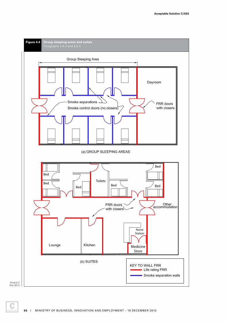
NurseStation
Bed
BedBed Bed
Bed
BedToilets
MedicineStore
Figure 4.4 Group sleeping areas and suites Paragraphs 4.6.4 and 4.6.5
Amend 2 Dec 2013
Acceptable Solution C/AS3
60 I MINISTRY OF BUSINESS, INNOVATION AND EMPLOYMENT – 19 DECEMBER 2013
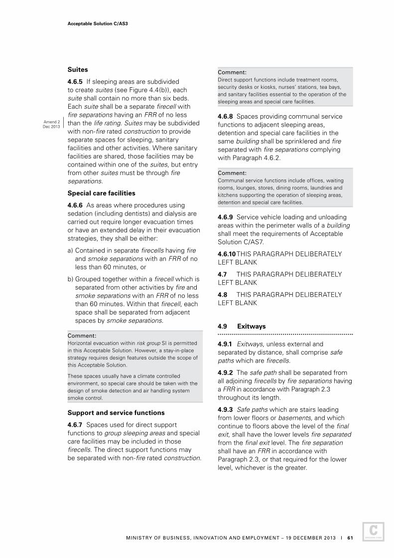
Suites
4.6.5 If sleeping areas are subdivided to create suites (see Figure 4.4(b)), each suite shall contain no more than six beds. Each suite shall be a separate firecell with fire separations having an FRR of no less than the life rating. Suites may be subdivided with non-fire rated construction to provide separate spaces for sleeping, sanitary facilities and other activities. Where sanitary facilities are shared, those facilities may be contained within one of the suites, but entry from other suites must be through fire separations.
Special care facilities
4.6.6 As areas where procedures using sedation (including dentists) and dialysis are carried out require longer evacuation times or have an extended delay in their evacuation strategies, they shall be either:
a) Contained in separate firecells having fire and smoke separations with an FRR of no less than 60 minutes, or
b) Grouped together within a firecell which is separated from other activities by fire and smoke separations with an FRR of no less than 60 minutes. Within that firecell, each space shall be separated from adjacent spaces by smoke separations.
Comment: Horizontal evacuation within risk group SI is permitted in this Acceptable Solution. However, a stay-in-place strategy requires design features outside the scope of this Acceptable Solution.
These spaces usually have a climate controlled environment, so special care should be taken with the design of smoke detection and air handling system smoke control.
Support and service functions
4.6.7 Spaces used for direct support functions to group sleeping areas and special care facilities may be included in those firecells. The direct support functions may be separated with non-fire rated construction.
Comment: Direct support functions include treatment rooms, security desks or kiosks, nurses’ stations, tea bays, and sanitary facilities essential to the operation of the sleeping areas and special care facilities.
4.6.8 Spaces providing communal service functions to adjacent sleeping areas, detention and special care facilities in the same building shall be sprinklered and fire separated with fire separations complying with Paragraph 4.6.2.
Comment: Communal service functions include offices, waiting rooms, lounges, stores, dining rooms, laundries and kitchens supporting the operation of sleeping areas, detention and special care facilities.
4.6.9 Service vehicle loading and unloading areas within the perimeter walls of a building shall meet the requirements of Acceptable Solution C/AS7.
4.6.10 THIS PARAGRAPH DELIBERATELY LEFT BLANK
4.7 THIS PARAGRAPH DELIBERATELY LEFT BLANK
4.8 THIS PARAGRAPH DELIBERATELY LEFT BLANK
4.9 Exitways
4.9.1 Exitways, unless external and separated by distance, shall comprise safe paths which are firecells.
4.9.2 The safe path shall be separated from all adjoining firecells by fire separations having a FRR in accordance with Paragraph 2.3 throughout its length.
4.9.3 Safe paths which are stairs leading from lower floors or basements, and which continue to floors above the level of the final exit, shall have the lower levels fire separated from the final exit level. The fire separation shall have an FRR in accordance with Paragraph 2.3, or that required for the lower level, whichever is the greater.
Amend 2Dec 2013
Acceptable Solution C/AS3
MINISTRY OF BUSINESS, INNOVATION AND EMPLOYMENT – 19 DECEMBER 2013 I 61

4.9.4 Safe paths which are long corridors shall be subdivided by smoke separations in accordance with Paragraph 4.12.
4.9.5 Air ducts passing through exitways shall not include combustible materials.
4.9.6 THIS PARAGRAPH DELIBERATELY LEFT BLANK
4.9.7 THIS PARAGRAPH DELIBERATELY LEFT BLANK
4.10 Intermittent activities
4.10.1 THIS PARAGRAPH DELIBERATELY LEFT BLANK
Solid waste storage
4.10.2 Solid waste storage areas shall be enclosed when located adjacent to occupied spaces; in other situations these areas may be unenclosed. Enclosed solid waste storage areas within any firecell shall themselves be a separate firecell separated from
adjacent firecells by fire separations having an FRR of no less than 60 minutes (see Paragraph 4.11.5 for waste chutes).
Plant, boiler and incinerator rooms
4.10.3 Any space within a building (see Figure 4.5) containing an incinerator, plant, boiler or machinery which uses solid fuel, gas or petroleum products as the energy source (but excluding space and local water heating appliances) shall be a separate firecell with an FRR of no less than 45 minutes, and shall have:
a) At least one external wall
b) External access that may be at any floor level including the roof. Where alternative internal access is provided, it shall be via a smoke lobby that is protected with a heat detector connected to a Type 2, 3, 4, or 5 system, and
c) Its floor level no lower than the ground level outside the external wall if gas is the energy source.
Figure 4.5 Plant, boiler and incinerator rooms Paragraph 4.10.3
Amend 3Jul 2014
Acceptable Solution C/AS3
62 I MINISTRY OF BUSINESS, INNOVATION AND EMPLOYMENT – 1 JULY 2014
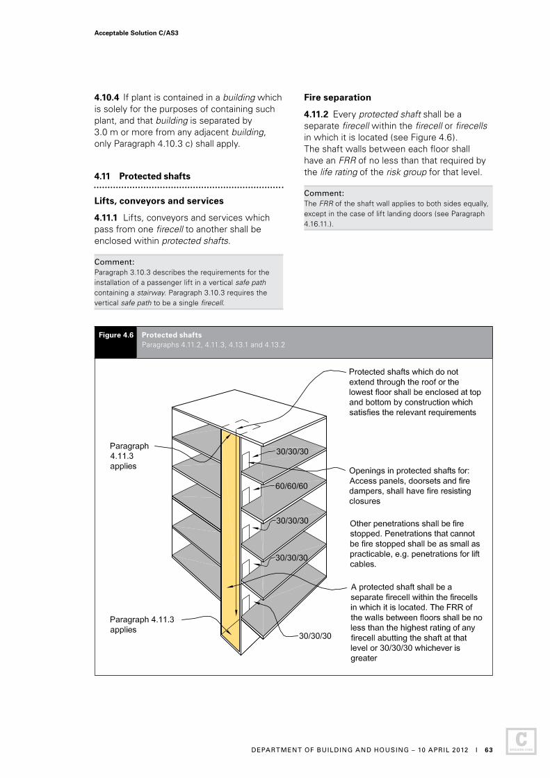
4.10.4 If plant is contained in a building which is solely for the purposes of containing such plant, and that building is separated by 3.0 m or more from any adjacent building, only Paragraph 4.10.3 c) shall apply.
4.11 Protected shafts
Lifts, conveyors and services
4.11.1 Lifts, conveyors and services which pass from one firecell to another shall be enclosed within protected shafts.
Comment: Paragraph 3.10.3 describes the requirements for the installation of a passenger lift in a vertical safe path containing a stairway. Paragraph 3.10.3 requires the vertical safe path to be a single firecell.
Fire separation
4.11.2 Every protected shaft shall be a separate firecell within the firecell or firecells in which it is located (see Figure 4.6). The shaft walls between each floor shall have an FRR of no less than that required by the life rating of the risk group for that level.
Comment: The FRR of the shaft wall applies to both sides equally, except in the case of lift landing doors (see Paragraph 4.16.11.).
Figure 4.6 Protected shafts Paragraphs 4.11.2, 4.11.3, 4.13.1 and 4.13.2
Acceptable Solution C/AS3
DEPARTMENT OF BUILDING AND HOUSING – 10 APRIL 2012 I 63
4.11.3 Protected shafts which do not extend through the roof or lowest floor shall be enclosed at top and bottom by construction which satisfies the relevant requirements of Paragraph 4.4 for fire stopping (see Figure 4.6).
Openings in protected shafts
4.11.4 There shall be no openings in protected shafts except for:
a) Access panels having an FRR of no less than that required for the shaft
b) Doorsets providing access to lifts and complying with smoke control requirements
c) Openings for lift ropes passing into a lift motor room, which shall be as small as practicable
d) Fire dampers serving a ventilation duct and complying with requirements for fire resisting closures
e) Penetrations which satisfy Paragraph 4.4 for fire stopping, or
f) Fittings with an FRR of no less than that required for the protected shaft.
Solid waste and linen chutes
4.11.5 Solid waste and linen chutes which pass from one firecell to another shall be protected shafts or contained within a protected shaft. Sprinklers shall be installed at the top of each chute and in the space into which the chute discharges.
4.11.6 Solid waste and linen chutes shall have no inlet or discharge openings within an exitway.
4.12 Long corridor subdivision
4.12.1 Long corridors shall be subdivided by smoke separations and smoke control doors (see Figure 4.7) which shall be evenly spaced along the corridor and no further apart than:
a) 60 m within open paths, or
b) 120 m within safe paths.
Comment:The smoke control doors are to swing both ways if required by Paragraphs 3.15.3 and 3.15.4.
Hold-open devices are required by Paragraph 3.15.9 to allow the doors to remain open during normal use of the building, but close automatically in the event of a fire.
4.13 Floors
4.13.1 Floors in buildings shall be fire separations (see Figure 4.6) except if the floor is the lowest floor above an unoccupied subfloor space, and complies with Paragraph 4.14.1.
4.13.2 Floors only need to be rated from the underside (see Figure 4.6). The FRR of a floor shall be that rating applicable to the firecell directly below the floor.
Intermediate floors
4.13.3 THIS PARAGRAPH DELIBERATELY LEFT BLANK
4.13.4 Intermediate floors and stairs used as access and their supporting primary elements within the firecell shall have FRRs of at least 30 minutes.
4.13.5 A firecell containing support functions to the sleeping firecell with an intermediate floor satisfying the following conditions may be treated as a single floor firecell if:
a) There is only one intermediate floor, and
b) The total occupant load on the intermediate floor is not greater than 100, and
c) The total area of the intermediate floor is no greater than specified in Paragraph 4.13.6.
4.13.6 The maximum total area of the intermediate floor within the firecell shall be the lowest of:
a) 40% of the area of the firecell floor not including the area of the intermediate floor, or
b) The area that allows up to 100 occupants on the intermediate floor based upon the occupant density of the space as calculated in accordance with Paragraph 1.4.
Acceptable Solution C/AS3
64 I DEPARTMENT OF BUILDING AND HOUSING – 10 APRIL 2012

Figure 4.7 Long corridor subdivision Paragraphs 4.12.1 and 4.16.8
Comment:Firecells containing intermediate floors require the same fire safety precautions as single level firecells having the same total occupant load and escape height.
As 100 occupants is the maximum occupant load of an intermediate floor (depending on the activity on that floor), the area of that floor cannot exceed that necessary to accommodate 100 people.
4.13.7 THIS PARAGRAPH DELIBERATELY LEFT BLANK
4.13.8 THIS PARAGRAPH DELIBERATELY LEFT BLANK
Basement floors
4.13.9 Basement firecells shall be separated from one another, and from the lowest firecell above ground level, by fire separations having FRRs in accordance with Paragraph 2.3.
Door closers are recommended on these doors if the corridor is an open path. Smoke control doors are required if the corridor is a smoke lobby, or fire doors if it is a safe path.
Acceptable Solution C/AS3
DEPARTMENT OF BUILDING AND HOUSING – 10 APRIL 2012 I 65

4.14 Subfloor spaces
4.14.1 In buildings with an unoccupied subfloor space between the ground and lowest floor (see Figure 4.8), the FRR of that floor shall be in accordance with Paragraph 2.3, except that no FRR is required if the following conditions are satisfied:
a) Vertical fire separations and external walls extend down to ground level and enclose the space, and
b) Access is available only for intermittent servicing of plumbing, drainage or other static services, and
Figure 4.8 Subfloor spaces Paragraph 4.14.1
c) The space is not used for storage and does not contain any installation such as machinery or heating appliances which could create a fire hazard, except when fire separated from the rest of the subfloor space.
Acceptable Solution C/AS3
66 I DEPARTMENT OF BUILDING AND HOUSING – 10 APRIL 2012

4.15 Concealed spaces
4.15.1 The spread of fire in concealed spaces and cavities shall be avoided by ensuring that extensive voids do not pass from one firecell to another, and by blocking off smaller voids with cavity barriers or, where appropriate, by using fire stops, see Paragraph 4.4.
Comment:Enclosing spaces with fire and smoke separations is one of the methods of controlling fire and smoke spread for satisfying this Acceptable Solution. However, if fire separations are internal walls, it is essential that those walls enclose any upper concealed space by extending beyond the ceiling to the floor or roof above.
Smoke detection and alarm systems are often relied on to provide building occupants, particularly sleeping risk groups, with early warning in the event of fire. However, where the smoke detectors are located only in the occupied spaces, smoke and fire can travel unobserved in upper concealed spaces that have not been fire or smoke separated. See Paragraph 4.15.2 for subdivision requirements for concealed spaces.
Concealed spaces within firecells
4.15.2 An upper concealed space may be used as an air handling plenum (see Figure 4.9) if the following requirements are satisfied:
a) The upper concealed space does not extend into another firecell
b) The ceiling and its supports and surfaces within the concealed space are non-combustible, and
c) Electrical wiring is supported clear of the ceiling members and other equipment, and
d) Any material used, such as pipe insulation or acoustic insulation, complies with the requirements of Table 4.1, and
e) Where the air handling plenum is used as an air supply path, a Type 3 or 4 system is installed with detectors in all return air ducts, and
f) Where the air handling plenum is used as an air supply path, detector activation causes the ventilation system to switch from circulation to extract as required by Paragraph 4.18.2.
Comment: Paragraph 4.15.2 e) and f) do not apply when the air handling plenum is used as an air exhaust path with a separate ducted air supply to the firecell.
Acceptable Solution C/AS3
DEPARTMENT OF BUILDING AND HOUSING – 10 APRIL 2012 I 67

Figure 4.9 Concealed spaces within firecells Paragraph 4.15.2
Acceptable Solution C/AS3
68 I DEPARTMENT OF BUILDING AND HOUSING – 10 APRIL 2012
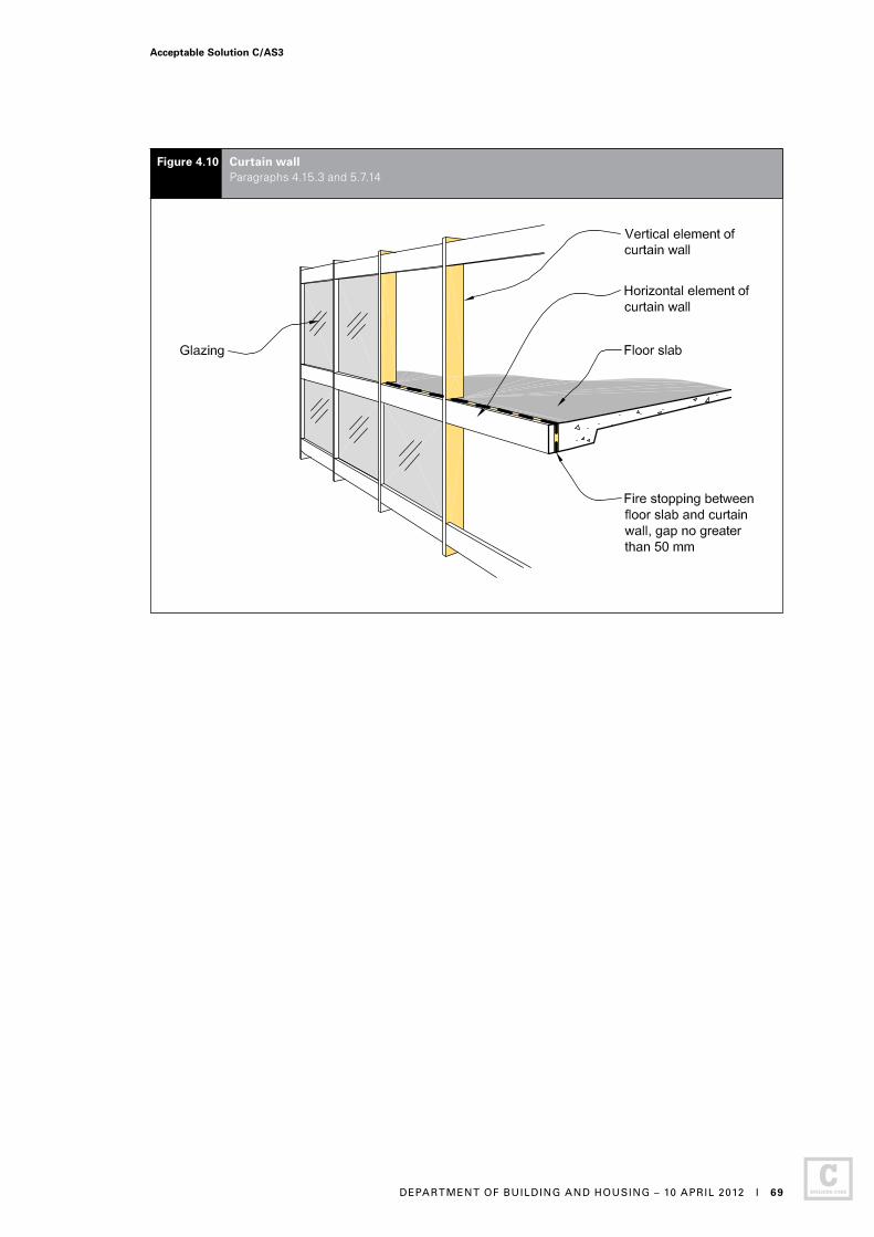
Figure 4.10 Curtain wall Paragraphs 4.15.3 and 5.7.14
Acceptable Solution C/AS3
DEPARTMENT OF BUILDING AND HOUSING – 10 APRIL 2012 I 69
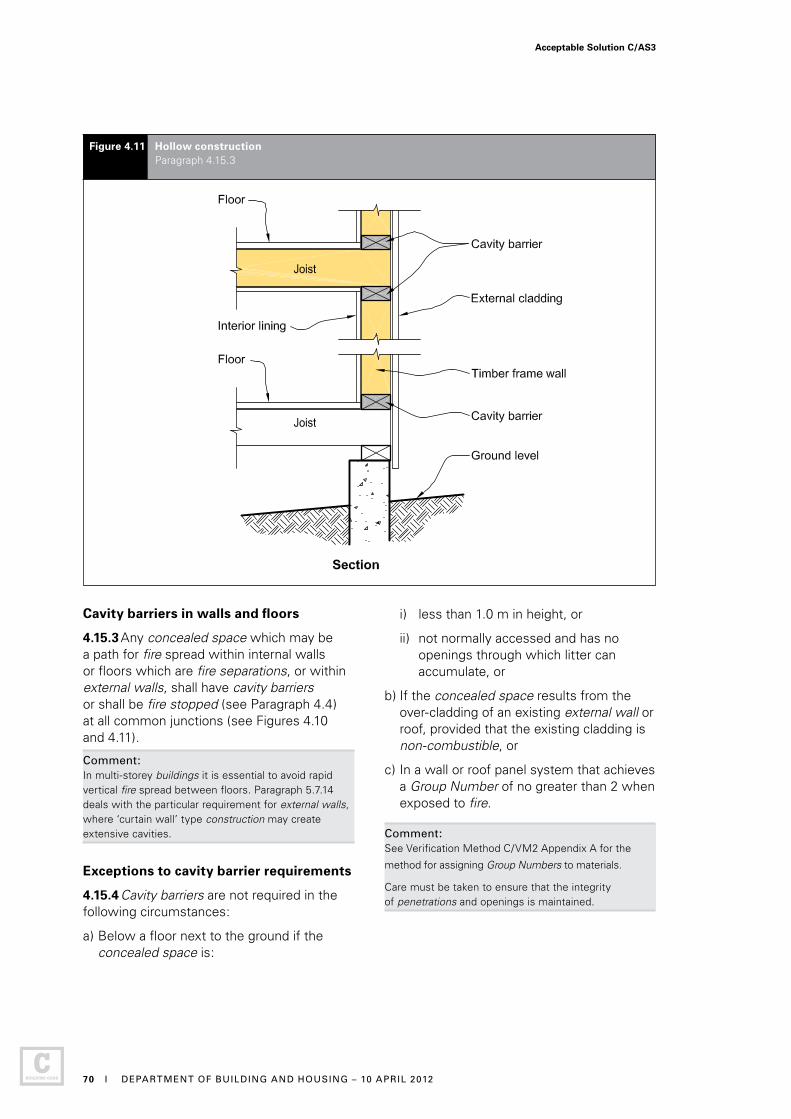
Figure 4.11 Hollow construction Paragraph 4.15.3
Cavity barriers in walls and floors
4.15.3 Any concealed space which may be a path for fire spread within internal walls or floors which are fire separations, or within external walls, shall have cavity barriers or shall be fire stopped (see Paragraph 4.4) at all common junctions (see Figures 4.10 and 4.11).
Comment:In multi-storey buildings it is essential to avoid rapid vertical fire spread between floors. Paragraph 5.7.14 deals with the particular requirement for external walls, where ‘curtain wall’ type construction may create extensive cavities.
Exceptions to cavity barrier requirements
4.15.4 Cavity barriers are not required in the following circumstances:
a) Below a floor next to the ground if the concealed space is:
i) less than 1.0 m in height, or
ii) not normally accessed and has no openings through which litter can accumulate, or
b) If the concealed space results from the over-cladding of an existing external wall or roof, provided that the existing cladding is non-combustible, or
c) In a wall or roof panel system that achieves a Group Number of no greater than 2 when exposed to fire.
Comment: See Verification Method C/VM2 Appendix A for the
method for assigning Group Numbers to materials.
Care must be taken to ensure that the integrity of penetrations and openings is maintained.
Acceptable Solution C/AS3
70 I DEPARTMENT OF BUILDING AND HOUSING – 10 APRIL 2012
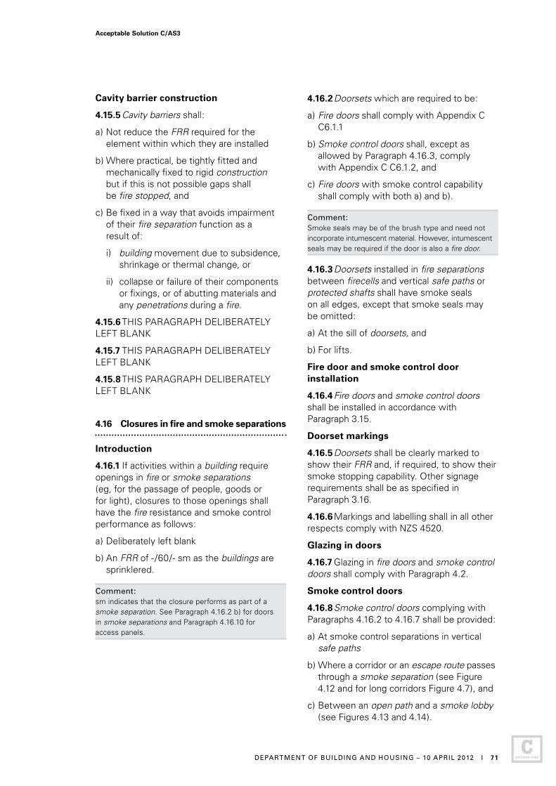
Cavity barrier construction
4.15.5 Cavity barriers shall:
a) Not reduce the FRR required for the element within which they are installed
b) Where practical, be tightly fitted and mechanically fixed to rigid construction but if this is not possible gaps shall be fire stopped, and
c) Be fixed in a way that avoids impairment of their fire separation function as a result of:
i) building movement due to subsidence, shrinkage or thermal change, or
ii) collapse or failure of their components or fixings, or of abutting materials and any penetrations during a fire.
4.15.6 THIS PARAGRAPH DELIBERATELY LEFT BLANK
4.15.7 THIS PARAGRAPH DELIBERATELY LEFT BLANK
4.15.8 THIS PARAGRAPH DELIBERATELY LEFT BLANK
4.16 Closures in fire and smoke separations
Introduction
4.16.1 If activities within a building require openings in fire or smoke separations (eg, for the passage of people, goods or for light), closures to those openings shall have the fire resistance and smoke control performance as follows:
a) Deliberately left blank
b) An FRR of - /60/- sm as the buildings are sprinklered.
Comment:sm indicates that the closure performs as part of a smoke separation. See Paragraph 4.16.2 b) for doors in smoke separations and Paragraph 4.16.10 for access panels.
4.16.2 Doorsets which are required to be:
a) Fire doors shall comply with Appendix C C6.1.1
b) Smoke control doors shall, except as allowed by Paragraph 4.16.3, comply with Appendix C C6.1.2, and
c) Fire doors with smoke control capability shall comply with both a) and b).
Comment: Smoke seals may be of the brush type and need not incorporate intumescent material. However, intumescent seals may be required if the door is also a fire door.
4.16.3 Doorsets installed in fire separations between firecells and vertical safe paths or protected shafts shall have smoke seals on all edges, except that smoke seals may be omitted:
a) At the sill of doorsets, and
b) For lifts.
Fire door and smoke control door installation
4.16.4 Fire doors and smoke control doors shall be installed in accordance with Paragraph 3.15.
Doorset markings
4.16.5 Doorsets shall be clearly marked to show their FRR and, if required, to show their smoke stopping capability. Other signage requirements shall be as specified in Paragraph 3.16.
4.16.6 Markings and labelling shall in all other respects comply with NZS 4520.
Glazing in doors
4.16.7 Glazing in fire doors and smoke control doors shall comply with Paragraph 4.2.
Smoke control doors
4.16.8 Smoke control doors complying with Paragraphs 4.16.2 to 4.16.7 shall be provided:
a) At smoke control separations in vertical safe paths
b) Where a corridor or an escape route passes through a smoke separation (see Figure 4.12 and for long corridors Figure 4.7), and
c) Between an open path and a smoke lobby (see Figures 4.13 and 4.14).
Acceptable Solution C/AS3
DEPARTMENT OF BUILDING AND HOUSING – 10 APRIL 2012 I 71
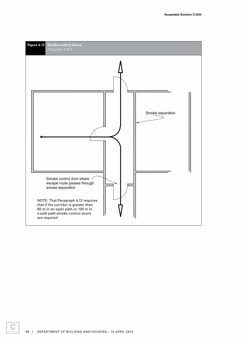
Figure 4.12 Smoke control doors Paragraph 4.16.8
NOTE: That Paragraph 4.12 requires that if the corridor is greater than 60 m in an open path or 120 m in a safe path smoke control doors are required
Acceptable Solution C/AS3
72 I DEPARTMENT OF BUILDING AND HOUSING – 10 APRIL 2012
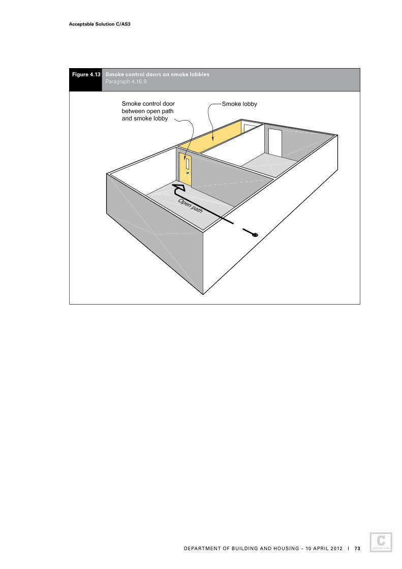
Figure 4.13 Smoke control doors on smoke lobbies Paragraph 4.16.8
Acceptable Solution C/AS3
DEPARTMENT OF BUILDING AND HOUSING – 10 APRIL 2012 I 73
Figure 4.14 Fire doors and smoke control doors Paragraphs 4.16.8 and 4.16.9
Acceptable Solution C/AS3
74 I DEPARTMENT OF BUILDING AND HOUSING – 10 APRIL 2012
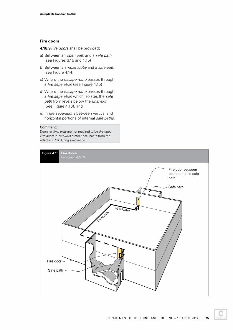
Figure 4.15 Fire doors Paragraph 4.16.9
Fire doors
4.16.9 Fire doors shall be provided:
a) Between an open path and a safe path (see Figures 3.15 and 4.15)
b) Between a smoke lobby and a safe path (see Figure 4.14)
c) Where the escape route passes through a fire separation (see Figure 4.15)
d) Where the escape route passes through a fire separation which isolates the safe path from levels below the final exit (See Figure 4.16), and
e) In fire separations between vertical and horizontal portions of internal safe paths.
Comment: Doors at final exits are not required to be fire rated. Fire doors in exitways protect occupants from the effects of fire during evacuation.
Acceptable Solution C/AS3
DEPARTMENT OF BUILDING AND HOUSING – 10 APRIL 2012 I 75

Figure 4.16 Fire doors to separate floors above and below final exit level Paragraph 4.16.9 d)
Acceptable Solution C/AS3
76 I DEPARTMENT OF BUILDING AND HOUSING – 10 APRIL 2012
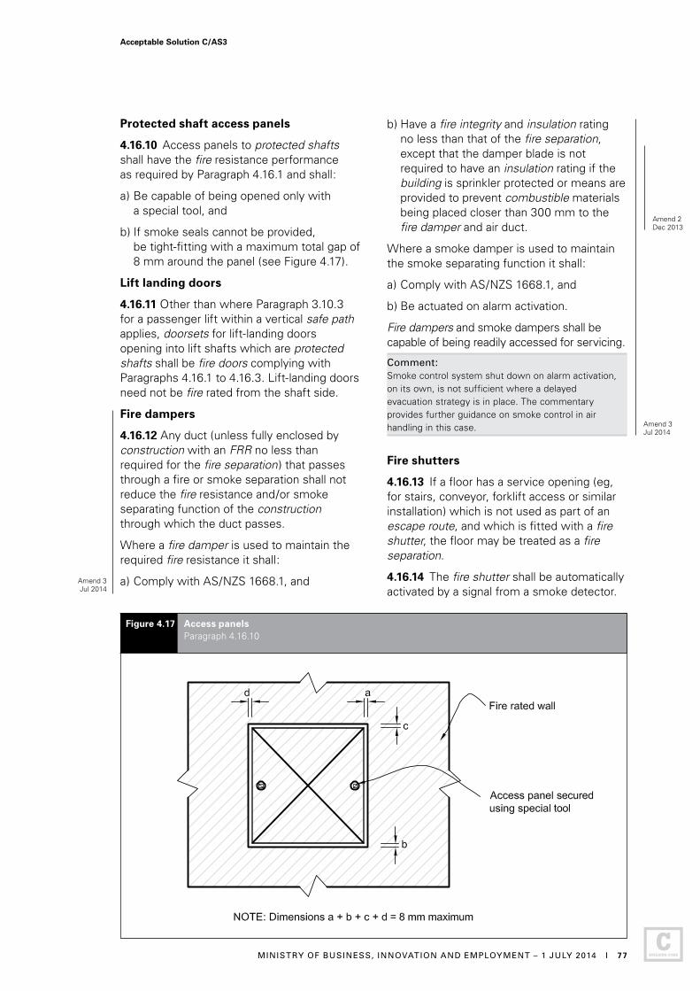
Figure 4.17 Access panels Paragraph 4.16.10
Protected shaft access panels
4.16.10 Access panels to protected shafts shall have the fire resistance performance as required by Paragraph 4.16.1 and shall:
a) Be capable of being opened only with a special tool, and
b) If smoke seals cannot be provided, be tight-fitting with a maximum total gap of 8 mm around the panel (see Figure 4.17).
Lift landing doors
4.16.11 Other than where Paragraph 3.10.3 for a passenger lift within a vertical safe path applies, doorsets for lift-landing doors opening into lift shafts which are protected shafts shall be fire doors complying with Paragraphs 4.16.1 to 4.16.3. Lift-landing doors need not be fire rated from the shaft side.
Fire dampers
4.16.12 Any duct (unless fully enclosed by construction with an FRR no less than required for the fire separation) that passes through a fire or smoke separation shall not reduce the fire resistance and/or smoke separating function of the construction through which the duct passes.
Where a fire damper is used to maintain the required fire resistance it shall:
a) Comply with AS/NZS 1668.1, and
b) Have a fire integrity and insulation rating no less than that of the fire separation, except that the damper blade is not required to have an insulation rating if the building is sprinkler protected or means are provided to prevent combustible materials being placed closer than 300 mm to the fire damper and air duct.
Where a smoke damper is used to maintain the smoke separating function it shall:
a) Comply with AS/NZS 1668.1, and
b) Be actuated on alarm activation.
Fire dampers and smoke dampers shall be capable of being readily accessed for servicing.
Comment: Smoke control system shut down on alarm activation, on its own, is not sufficient where a delayed evacuation strategy is in place. The commentary provides further guidance on smoke control in air handling in this case.
Fire shutters
4.16.13 If a floor has a service opening (eg, for stairs, conveyor, forklift access or similar installation) which is not used as part of an escape route, and which is fitted with a fire shutter, the floor may be treated as a fire separation.
4.16.14 The fire shutter shall be automatically activated by a signal from a smoke detector.
Amend 2Dec 2013
Amend 3Jul 2014
Amend 3Jul 2014
Acceptable Solution C/AS3
MINISTRY OF BUSINESS, INNOVATION AND EMPLOYMENT – 1 JULY 2014 I 77
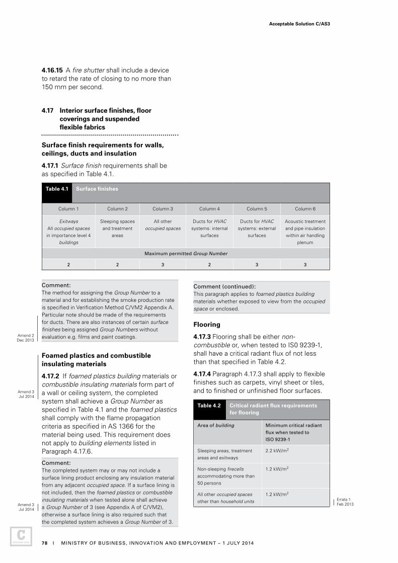
4.16.15 A fire shutter shall include a device to retard the rate of closing to no more than 150 mm per second.
4.17 Interior surface finishes, floor coverings and suspended flexible fabrics
Surface finish requirements for walls, ceilings, ducts and insulation
4.17.1 Surface finish requirements shall be as specified in Table 4.1.
Table 4.1 Surface finishes
Column 1 Column 2 Column 3 Column 4 Column 5 Column 6
ExitwaysAll occupied spaces in importance level 4
buildings
Sleeping spaces and treatment
areas
All other occupied spaces
Ducts for HVAC systems: internal
surfaces
Ducts for HVAC systems: external
surfaces
Acoustic treatment and pipe insulation within air handling
plenum
Maximum permitted Group Number
2 2 3 2 3 3
Comment:The method for assigning the Group Number to a material and for establishing the smoke production rate is specified in Verification Method C/VM2 Appendix A. Particular note should be made of the requirements for ducts. There are also instances of certain surface finishes being assigned Group Numbers without evaluation e.g. films and paint coatings.
Foamed plastics and combustible insulating materials
4.17.2 If foamed plastics building materials or combustible insulating materials form part of a wall or ceiling system, the completed system shall achieve a Group Number as specified in Table 4.1 and the foamed plastics shall comply with the flame propagation criteria as specified in AS 1366 for the material being used. This requirement does not apply to building elements listed in Paragraph 4.17.6.
Comment:The completed system may or may not include a surface lining product enclosing any insulation material from any adjacent occupied space. If a surface lining is not included, then the foamed plastics or combustible insulating materials when tested alone shall achieve a Group Number of 3 (see Appendix A of C/VM2), otherwise a surface lining is also required such that the completed system achieves a Group Number of 3.
Comment (continued):This paragraph applies to foamed plastics building materials whether exposed to view from the occupied space or enclosed. Flooring
4.17.3 Flooring shall be either non-combustible or, when tested to IS0 9239-1, shall have a critical radiant flux of not less than that specified in Table 4.2.
4.17.4 Paragraph 4.17.3 shall apply to flexible finishes such as carpets, vinyl sheet or tiles, and to finished or unfinished floor surfaces.
Table 4.2 Critical radiant flux requirements for flooring
Area of building Minimum critical radiant
flux when tested to
ISO 9239-1
Sleeping areas, treatment areas and exitways
2.2 kW/m2
Non-sleeping firecells accommodating more than 50 persons
1.2 kW/m2
All other occupied spaces other than household units
1.2 kW/m2
Errata 1Feb 2013
Amend 2Dec 2013
Amend 3Jul 2014
Amend 3Jul 2014
Acceptable Solution C/AS3
78 I MINISTRY OF BUSINESS, INNOVATION AND EMPLOYMENT – 1 JULY 2014
Wood and wood products in floors
4.17.5 In addition to the requirements of Paragraph 4.17.3, where floors in multi-storey buildings are fire separations and where the flooring material is made of wood products (wood products include boards manufactured from wood fibres or chips bound by an adhesive) the flooring material shall have either a thickness of no less than nominally 20 mm, or the floor assembly shall have an FRR of - /30/30 when exposed to fire from the flooring side.
Comment: 1. Nominal 20 mm thickness includes standard
flooring products such as 19 mm particle board or 17 mm plywood. These are acceptable.
2. Paragraph 4.17.5 addresses potential fire spread from the upper to lower firecell by limiting fire spread down through the floor assembly. Protecting the upper firecell from a fire in the lower firecell is still also a requirement, achieved by use of fire separations as described in Paragraph 4.13.
Exceptions to surface finish requirements
4.17.6 Surface finish requirements do not apply to:
a) Small areas of non-conforming product within a firecell with a total aggregate surface area of not more than 5.0 m2
b) Electrical switches, outlets, cover plates and similar small discontinuous areas
c) Pipes and cables used to distribute power or services
d) Handrails and general decorative trim of any material such as architraves, skirtings and window components, including reveals, provided these do not exceed 5% of the surface area of the wall or ceiling they are part of
e) Damp-proof courses, seals, caulking, flashings, thermal breaks and ground moisture barriers
f) Timber joinery and structural timber building elements constructed from solid wood, glulam or laminated veneer lumber. This includes heavy timber columns, beams, portals and shear walls not more than 3.0 m wide, but does not include exposed timber panels or permanent formwork on the underside of floor/ceiling systems
g) Individual doorsets, and
h) Continuous areas of permanently installed openable wall partitions having a surface area of not more than 25% of the divided room floor area or 5.0 m2, whichever is less
i) DELIBERATELY LEFT BLANK.
j) DELIBERATELY LEFT BLANK.
4.17.7 THIS PARAGRAPH DELIBERATELY LEFT BLANK
Suspended flexible fabrics
4.17.8 When tested to AS 1530 Part 2, suspended flexible fabrics shall, within all occupied spaces including exitways:
a) Have a flammability index of no greater than 12, and
b) When used as underlay to roofing or exterior cladding that is exposed to view, have a flammability index of no greater than 5.
4.17.9 THIS PARAGRAPH DELIBERATELY LEFT BLANK
4.17.10 THIS PARAGRAPH DELIBERATELY LEFT BLANK
Air ducts
4.17.11 Where air ducts are contained wholly within a protected shaft, provided the shaft does not also contain lifts, only the interior surface finish of the air duct is required to comply with Table 4.1.
4.18 Building services plant
Automatic activation
4.18.1 When any smoke detection system is activated, it shall automatically turn off all air-conditioning and mechanical ventilation plant which is not required or designed for fire safety.
Comment:Paragraph 4.18.1 does not apply to non-distributed ventilation and air-conditioning such as typical domestic/commercial heat pump units.
Air handling systems
4.18.2 Where smoke control in air handling systems is required to prevent the recirculation of smoke through an air handling system to other firecells in a building, these systems shall be as specified in Appendix A A2.1.
Amend 2Dec 2013
Amend 2Dec 2013
Amend 3Jul 2014
Amend 3Jul 2014
Acceptable Solution C/AS3
MINISTRY OF BUSINESS, INNOVATION AND EMPLOYMENT – 1 JULY 2014 I 79

Part 5: Control of external fire spread
CONTENTS
5.1 Fire separation for buildings with more than one title
5.2 Horizontal fire spread from external walls
5.3 FRRs of external walls
5.4 Small openings and fire resisting glazing
5.5 Table method for external walls
5.6 Horizontal fire spread from roofs and open sided buildings
5.7 Vertical fire spread
5.8 Exterior surface finishes
5.1 Fire separation for buildings with more than one title
5.1.1 When a building is subdivided so that the building straddles more than one title, each part of the building located on a separate title, other than titles comprising vehicle parking, areas shall be separated from:
a) The part of the building on an adjacent title by fire separations having an FRR meeting the property rating in accordance with Paragraph 2.3, and
b) Any external area in common, unless Paragraph 5.1.2 applies, by external walls complying with Paragraph 5.3 except that, if roofed, the area in common shall be a firecell separated from adjacent titles by fire separations meeting the property rating in accordance with Paragraph 2.3.
Comment:In a) above, vertical fire separations provide fire ratings between titles. Floors between titles are also fire separations and provide the horizontal separation. See Acceptable Solution C/AS7 for allowances in vehicle parking areas of buildings separated into multiple titles.
In b) above, a notional boundary is established between the titles, and the permitted unprotected area in the external walls of both titles is determined with respect to that notional boundary. When the area in common is roofed, the danger to life and adjacent property is increased; hence the need for greater precautions.
5.1.2 If a building is subdivided (as in Paragraph 5.1.1 a)) and all the titles and any areas in common are sprinklered throughout, the requirements for fire separations of Paragraph 5.1.1 b) need not apply. However, the requirements for fire separation of safe paths in Paragraphs 4.9.2 and 4.9.3 shall still apply.
Acceptable Solution C/AS3
80 I DEPARTMENT OF BUILDING AND HOUSING – 10 APRIL 2012
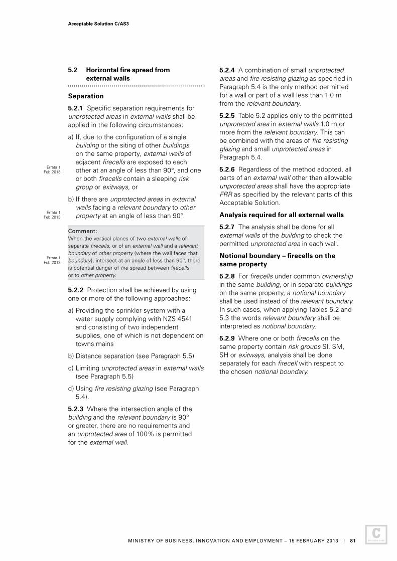
5.2 Horizontal fire spread from external walls
Separation
5.2.1 Specific separation requirements for unprotected areas in external walls shall be applied in the following circumstances:
a) If, due to the configuration of a single building or the siting of other buildings on the same property, external walls of adjacent firecells are exposed to each other at an angle of less than 90°, and one or both firecells contain a sleeping risk group or exitways, or
b) If there are unprotected areas in external walls facing a relevant boundary to other property at an angle of less than 90°.
Comment:When the vertical planes of two external walls of separate firecells, or of an external wall and a relevant boundary of other property (where the wall faces that boundary), intersect at an angle of less than 90°, there is potential danger of fire spread between firecells or to other property.
5.2.2 Protection shall be achieved by using one or more of the following approaches:
a) Providing the sprinkler system with a water supply complying with NZS 4541 and consisting of two independent supplies, one of which is not dependent on towns mains
b) Distance separation (see Paragraph 5.5)
c) Limiting unprotected areas in external walls (see Paragraph 5.5)
d) Using fire resisting glazing (see Paragraph 5.4).
5.2.3 Where the intersection angle of the building and the relevant boundary is 90° or greater, there are no requirements and an unprotected area of 100% is permitted for the external wall.
5.2.4 A combination of small unprotected areas and fire resisting glazing as specified in Paragraph 5.4 is the only method permitted for a wall or part of a wall less than 1.0 m from the relevant boundary.
5.2.5 Table 5.2 applies only to the permitted unprotected area in external walls 1.0 m or more from the relevant boundary. This can be combined with the areas of fire resisting glazing and small unprotected areas in Paragraph 5.4.
5.2.6 Regardless of the method adopted, all parts of an external wall other than allowable unprotected areas shall have the appropriate FRR as specified by the relevant parts of this Acceptable Solution.
Analysis required for all external walls
5.2.7 The analysis shall be done for all external walls of the building to check the permitted unprotected area in each wall.
Notional boundary – firecells on the same property
5.2.8 For firecells under common ownership in the same building, or in separate buildings on the same property, a notional boundary shall be used instead of the relevant boundary. In such cases, when applying Tables 5.2 and 5.3 the words relevant boundary shall be interpreted as notional boundary.
5.2.9 Where one or both firecells on the same property contain risk groups SI, SM, SH or exitways, analysis shall be done separately for each firecell with respect to the chosen notional boundary.
Errata 1Feb 2013
Errata 1Feb 2013
Errata 1Feb 2013
Acceptable Solution C/AS3
MINISTRY OF BUSINESS, INNOVATION AND EMPLOYMENT – 15 FEBRUARY 2013 I 81

5.3 FRRs of external walls
5.3.1 Building elements that are part of an external wall that is required to be fire rated shall be fire rated as required by Paragraph 2.3. If a safe path has an external wall that is required to be fire rated, that wall may be 100% unprotected provided any walls between the safe path and adjacent firecells have an FRR determined using the property rating.
5.3.2 Any part of an external wall enclosing a firecell and not permitted to be an unprotected area shall have an FRR in accordance with Paragraph 2.3. If the external wall is less than 1.0 m from the relevant boundary the wall shall be fire rated to protect from both directions.
5.3.3 When the unprotected area of an external wall is permitted to be 100%, but the primary elements in the line of that wall are required to be fire rated, the rating of those primary elements shall be the life rating in accordance with Paragraph 2.3.
Comment: Primary elements are required to be fire rated in buildings with an escape height of greater than 25 m and where they support, or are an integral part of, other fire rated building elements.
5.4 Small openings and fire resisting glazing
5.4.1 External wall construction shall meet the following requirements:
a) Unprotected areas (referred to as Type A areas) and areas of fire resisting glazing (referred to as Type B areas) shall be located to comply with Figure 5.1, and
b) The remainder of the wall shall be fire rated equally for exposure to fire on both sides.
Size and spacing of Type A and Type B areas
5.4.2 Type A areas shall be no greater than 0.1 m2. Type B areas are unlimited in size in this risk group, but the spacing of Type B areas shall comply with Figure 5.1.
5.4.3 There is no restriction on the area of fire resisting glazing in this Acceptable Solution. The fire resisting glazing shall be rated for integrity and the FRR of both the glazing and the external wall shall be as required by Paragraph 2.3.
5.4.4 There is no limitation on the spacing between adjacent Type A and Type B areas which occur in different firecells. Within a firecell the following requirements shall apply:
a) Type A areas shall be no closer, both vertically and horizontally, than 1.5 m to another Type A or to a Type B area
b) Type B areas shall be no closer to one another, vertically or horizontally, than the dimensions X or Y shown on Figure 5.1, and
c) Where Type B areas are staggered, rather than being aligned vertically or horizontally, the shortest distance, in any direction, between adjacent areas shall be no less than the greater of the X and Y measurements.
Table 5.1: This table is not required for this Acceptable Solution.
5.5 Table method for external walls
5.5.1 The table method for external walls is the means of satisfying the requirements of this Acceptable Solution for the control of external fire spread and shall be applied to external walls of buildings which are parallel to or angled at less than 90° to the relevant boundary. Table 5.2 is split into three parts according to the angle incident between the subject wall and the relevant boundary. If the wall is parallel to the boundary or the angle is less than 45°, then columns 2 and 3 shall be used (see Figures 5.2 and 5.3).
5.5.2 The table method shall be used to determine the percentage of unprotected area in the external wall of each firecell depending on the distance to the relevant boundary.
Errata 1Feb 2013
Amend 3 Jul 2014
Acceptable Solution C/AS3
82 I MINISTRY OF BUSINESS, INNOVATION AND EMPLOYMENT – 1 JULY 2014
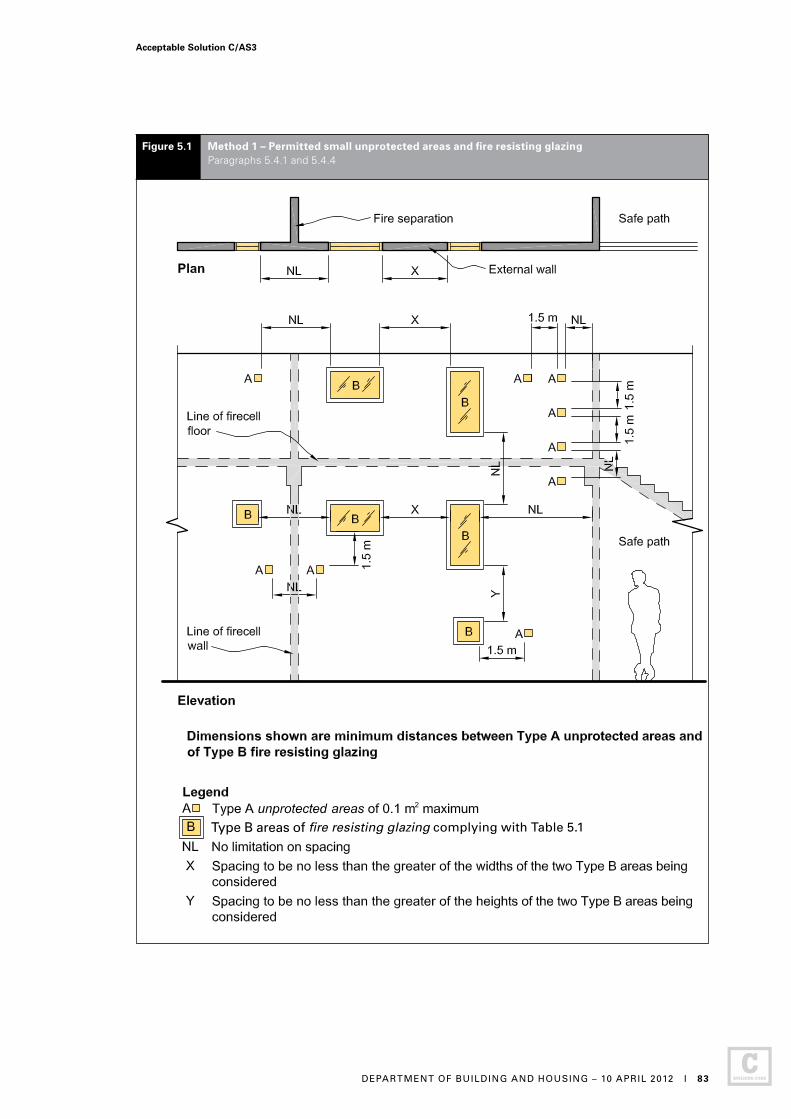
Figure 5.1 Method 1 – Permitted small unprotected areas and fire resisting glazing Paragraphs 5.4.1 and 5.4.4
Type B areas of fire resisting glazing fire resisting glazing complying with Table 5.1
Acceptable Solution C/AS3
DEPARTMENT OF BUILDING AND HOUSING – 10 APRIL 2012 I 83
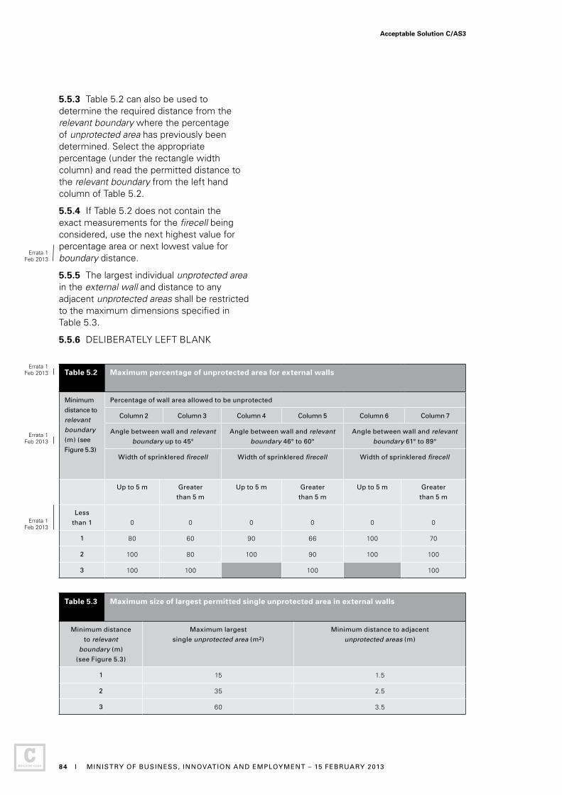
5.5.3 Table 5.2 can also be used to determine the required distance from the relevant boundary where the percentage of unprotected area has previously been determined. Select the appropriate percentage (under the rectangle width column) and read the permitted distance to the relevant boundary from the left hand column of Table 5.2.
5.5.4 If Table 5.2 does not contain the exact measurements for the firecell being considered, use the next highest value for percentage area or next lowest value for boundary distance.
5.5.5 The largest individual unprotected area in the external wall and distance to any adjacent unprotected areas shall be restricted to the maximum dimensions specified in Table 5.3.
5.5.6 DELIBERATELY LEFT BLANK
Table 5.2g Maximum percentage of unprotected area for external walls
Minimum
distance to
relevant
boundary
(m) (see
Figure 5.3)
Percentage of wall area allowed to be unprotected
Column 2 Column 3 Column 4 Column 5 Column 6 Column 7
Angle between wall and relevant
boundary up to 45°
Angle between wall and relevant
boundary 46° to 60°
Angle between wall and relevant
boundary 61° to 89°
Width of sprinklered firecell Width of sprinklered firecell Width of sprinklered firecell
Up to 5 m Greater
than 5 m
Up to 5 m Greater
than 5 m
Up to 5 m Greater
than 5 m
Less
than 1 0 0 0 0 0 0
1 80 60 90 66 100 70
2 100 80 100 90 100 100
3 100 100 100 100
Table 5.3 Maximum size of largest permitted single unprotected area in external walls
Minimum distance
to relevant
boundary (m)
(see Figure 5.3)
Maximum largest
single unprotected area (m2)
Minimum distance to adjacent
unprotected areas (m)
1 15 1.5
2 35 2.5
3 60 3.5
Errata 1Feb 2013
Errata 1Feb 2013
Errata 1Feb 2013
Errata 1Feb 2013
Acceptable Solution C/AS3
84 I MINISTRY OF BUSINESS, INNOVATION AND EMPLOYMENT – 15 FEBRUARY 2013

Figure 5.2 Separation of unprotected areas Paragraph 5.5.1
Acceptable Solution C/AS3
DEPARTMENT OF BUILDING AND HOUSING – 10 APRIL 2012 I 85
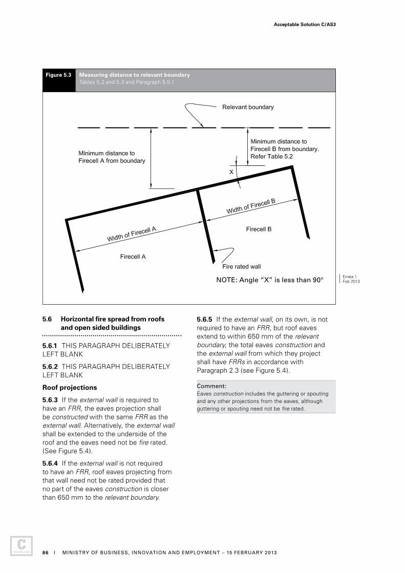
5.6 Horizontal fire spread from roofs and open sided buildings
5.6.1 THIS PARAGRAPH DELIBERATELY LEFT BLANK
5.6.2 THIS PARAGRAPH DELIBERATELY LEFT BLANK
Roof projections
5.6.3 If the external wall is required to have an FRR, the eaves projection shall be constructed with the same FRR as the external wall. Alternatively, the external wall shall be extended to the underside of the roof and the eaves need not be fire rated. (See Figure 5.4).
5.6.4 If the external wall is not required to have an FRR, roof eaves projecting from that wall need not be rated provided that no part of the eaves construction is closer than 650 mm to the relevant boundary.
Figure 5.3 Measuring distance to relevant boundary Tables 5.2 and 5.3 and Paragraph 5.5.1
5.6.5 If the external wall, on its own, is not required to have an FRR, but roof eaves extend to within 650 mm of the relevant boundary, the total eaves construction and the external wall from which they project shall have FRRs in accordance with Paragraph 2.3 (see Figure 5.4).
Comment: Eaves construction includes the guttering or spouting and any other projections from the eaves, although guttering or spouting need not be fire rated.
NOTE: Angle “X” is less than 90°Errata 1Feb 2013
Acceptable Solution C/AS3
86 I MINISTRY OF BUSINESS, INNOVATION AND EMPLOYMENT – 15 FEBRUARY 2013
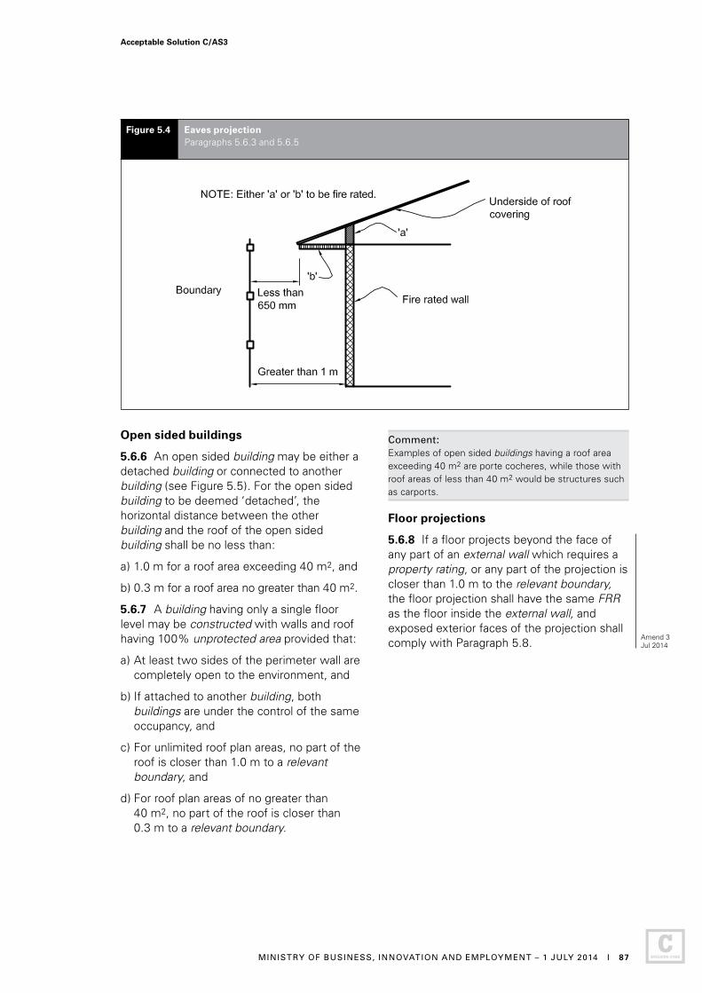
Open sided buildings
5.6.6 An open sided building may be either a detached building or connected to another building (see Figure 5.5). For the open sided building to be deemed ‘detached’, the horizontal distance between the other building and the roof of the open sided building shall be no less than:
a) 1.0 m for a roof area exceeding 40 m2, and
b) 0.3 m for a roof area no greater than 40 m2.
5.6.7 A building having only a single floor level may be constructed with walls and roof having 100% unprotected area provided that:
a) At least two sides of the perimeter wall are completely open to the environment, and
b) If attached to another building, both buildings are under the control of the same occupancy, and
c) For unlimited roof plan areas, no part of the roof is closer than 1.0 m to a relevant boundary, and
d) For roof plan areas of no greater than 40 m2, no part of the roof is closer than 0.3 m to a relevant boundary.
Figure 5.4 Eaves projection Paragraphs 5.6.3 and 5.6.5
Comment: Examples of open sided buildings having a roof area exceeding 40 m2 are porte cocheres, while those with roof areas of less than 40 m2 would be structures such as carports.
Floor projections
5.6.8 If a floor projects beyond the face of any part of an external wall which requires a property rating, or any part of the projection is closer than 1.0 m to the relevant boundary, the floor projection shall have the same FRR as the floor inside the external wall, and exposed exterior faces of the projection shall comply with Paragraph 5.8.
Acceptable Solution C/AS3
MINISTRY OF BUSINESS, INNOVATION AND EMPLOYMENT – 1 JULY 2014 I 87
Amend 3 Jul 2014

Figure 5.5 Open sided buildings – distance and FRR requirements Paragraph 5.6.6
Separation distances for non-fire rated constructionWhen Ar is no greater than 40 m2, ‘Z’ shall be no less than 0.3 m. When Ar exceeds 40 m2, ‘Z’ shall be no less than 1.0 m.
Acceptable Solution C/AS3
88 I DEPARTMENT OF BUILDING AND HOUSING – 10 APRIL 2012

5.7 Vertical fire spread
Roofs
5.7.1 Sleeping risk groups, other property and external exitways shall be protected against vertical fire spread from roofs.
5.7.2 Sprinklers are required in the firecell below the roof. This achieves the requirement for protection against vertical fire spread.
External exitways over roofs
5.7.3 Subject to Paragraph 3.11.3, when an external exitway crosses a roof, or is above or adjacent to a roof on the same or another building, the roof within 3.0 m of any part of the exitway and all supporting elements shall have an FRR in accordance with Paragraph 2.3.
Primary elements
5.7.4 Primary elements providing support to an area of fire rated roof shall have an FRR of no less than that of the roof.
5.7.5 When supporting an unrated roof:
a) Primary elements such as columns or walls which are required to be fire rated shall be rated from floor level to the underside of the roof framing members, and
b) Any roof framing members connected to these fire rated columns or walls shall also be rated if their collapse in fire would cause the consequential collapse of the rated columns or walls.
Fire spread from an adjacent lower roof
5.7.6 THIS PARAGRAPH DELIBERATELY LEFT BLANK
5.7.7 THIS PARAGRAPH DELIBERATELY LEFT BLANK
5.7.8 THIS PARAGRAPH DELIBERATELY LEFT BLANK
5.7.9 THIS PARAGRAPH DELIBERATELY LEFT BLANK
Comment:Risk group SI is required to have automatic sprinklers installed. Therefore, there are no further requirements to protect against fire spread from an adjacent roof.
External fire spread between different levels of the same building
5.7.10 THIS PARAGRAPH DELIBERATELY LEFT BLANK
5.7.11 THIS PARAGRAPH DELIBERATELY LEFT BLANK
5.7.12 THIS PARAGRAPH DELIBERATELY LEFT BLANK
Table 5.4: This Table is not required for this Acceptable Solution
5.7.13 THIS PARAGRAPH DELIBERATELY LEFT BLANK
5.7.14 Where there is a gap between an external wall and a fire separation which together enclose a firecell, the space between the fire separation and the external wall shall be no greater than 50 mm and shall be fire stopped (see Paragraphs 4.15.3 to 4.15.5 and Figure 4.10).
5.7.15 Eaves and floors overhanging an external wall shall be protected as required by Paragraphs 5.6.3 and 5.6.4.
Comment:Risk group SI is required to have automatic sprinklers installed. Therefore, there are no further requirements to protect against fire spread from other levels of the same building.
5.7.16 THIS PARAGRAPH DELIBERATELY LEFT BLANK
External thermal insulation on walls in multi-storey buildings
5.7.17 Buildings of three or more floors with an external wall cladding system incorporating an externally applied combustible insulant shall have horizontal fire stop barriers installed in the cladding system at intervals of not more than two floors. For framed wall systems, a barrier shall be constructed within the framed cavity, and a fire stop barrier shall be constructed at the same level within the cladding system. An acceptable detail for barriers is shown in Figure 5.8. This requirement does not apply to combustible insulant positioned between studs and dwangs/nogs in a conventional framed wall system.
Acceptable Solution C/AS3
DEPARTMENT OF BUILDING AND HOUSING – 10 APRIL 2012 I 89
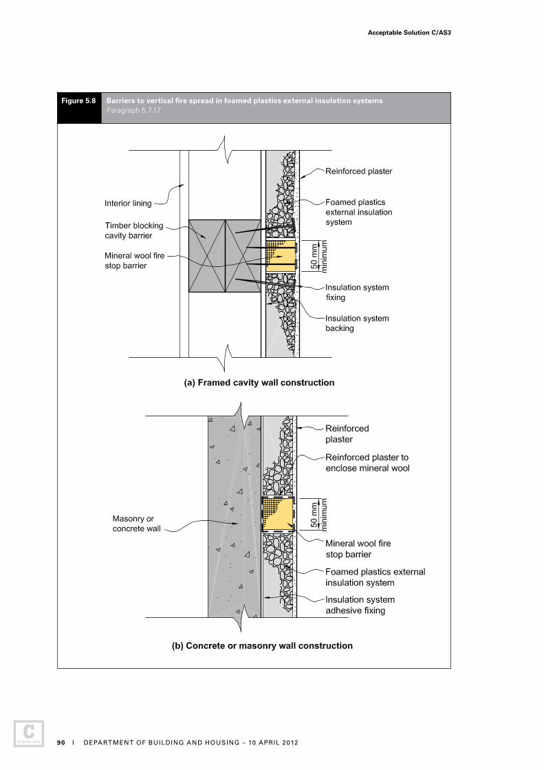
Figure 5.8 Barriers to vertical fire spread in foamed plastics external insulation systems Paragraph 5.7.17
Acceptable Solution C/AS3
90 I DEPARTMENT OF BUILDING AND HOUSING – 10 APRIL 2012
5.7.18 Paragraph 5.7.17 applies where the floors are fire separations between firecells. It does not apply to any external wall satisfying the test requirements of Paragraph 5.8.2 b).
Comment:Horizontal fire stop barriers are needed to prevent progressive involvement of insulants in fire by restricting hot gases or flames from travelling upwards within the insulation layer. In practice, it may be necessary to specify movement joints to control cracking of the render or surface coating. These may be conveniently incorporated within barriers. Further guidance and suitable fire barrier details may be found in BRE Defect Action Sheet DAS 131 with additional information provided in BRE Report 135.
Combustible insulants may include expanded polystyrene (EPS), polyisocyanurate, or polyurethane. The insulants may be covered on the exterior side with a sheet material or with a thin rendered cementitious or polymeric coating. However, Paragraph 5.7.17 still applies.
5.8 Exterior surface finishes
External walls
5.8.1 The external wall cladding system shall be tested in accordance with the relevant standard test in Appendix C C7.1 and shall satisfy the following requirements:
a) If the distance to the relevant boundary is less than 1.0 m or where the building height is more than 7.0 m, the peak heat release rate shall not exceed 100 kW/m2 and the total heat released shall not exceed 25 MJ/m2, and
b) If the distance to the relevant boundary is 1.0 m or more and the building height is 7.0 m or less, unless the building is single storey, the peak heat release rate shall not exceed 150 kW/m2 and the total heat released shall not exceed 50 MJ/m2.
5.8.2 The requirements in Paragraph 5.8.1 do not apply if:
a) Surface finishes are no more than 1 mm in thickness and applied directly to a non-combustible substrate, or
b) The entire wall assembly has been tested at full scale in accordance with NFPA 285 and has passed the test criteria.
5.8.3 THIS PARAGRAPH DELIBERATELY LEFT BLANK
5.8.4 If a building has firecells containing different risk groups, the acceptable peak heat release rate and total heat released of an external wall cladding system may have different values provided that:
a) For each risk group the value is no greater than required by Paragraph 5.8.1 for the building height (not just the height of the firecell), and
b) The value applied to a firecell is no greater than required by any firecells at a higher level on that wall.
Comment:For external walls, the acceptable properties of external wall cladding systems depend on the building height, presence of sprinklers and the distance from the relevant boundary.
An external wall cladding system includes any applied surface finish such as paint or other coating combined with the substrate material. Fire tests should be carried out on samples representative of the finished product as used on the building, to determine compliance.
While the specific heat release rate of a cladding system must be verified by standard test results, the following is an indication of the performance of some types of construction:
• Non-combustible materials such as concrete, brick, glass and steel meet the requirements of Paragraph 5.8.1
• Cellulose fibre-cement products with applied finishes/coatings less than 1 mm thick would usually meet the requirements of Paragraph 5.8.1, and
• Ordinary timber products would not usually meet the requirements of Paragraph 5.8.1.
Where the combustibility of a timber product is modified through the application of a fire retardant treatment to meet the requirements of Paragraph 5.8.1, it is to be subjected to pre-test accelerated weathering as described in Appendix C C7.1.3.
Errata 1Feb 2013
Acceptable Solution C/AS3
MINISTRY OF BUSINESS, INNOVATION AND EMPLOYMENT – 15 FEBRUARY 2013 I 91
Part 6: Firefighting
CONTENTS
6.1 Fire service vehicular access
6.2 Information for firefighters
6.3 Access within the building for firefighting and rescue operations
6.4 Firefighting facilities
6.1 Fire Service vehicular access
6.1.1 If buildings are located remotely from the street boundaries of a property, pavements situated on the property and likely to be used for vehicular access by fire appliances shall:
a) Be able to withstand a laden weight of up to 25 tonnes with an axle load of 8 tonnes or have a load-bearing capacity of no less than the public roadway serving the property, whichever is the lower, and
b) Be trafficable in all weathers, and
c) Have a minimum width of 4.0 m, and
d) Provide a clear passageway of no less than 3.5 m in width and 4.0 m in height at site entrances, internal entrances and between buildings, and
e) Provide access to a hard-standing within 20 m of
i) an entrance to the building, and
ii) any inlets to the fire sprinkler or building fire hydrant systems.
Comment: Access to buildings for fire appliances will be generally via public streets, but provision is needed on large, multi- building sites to enable appliances to reach any building.
6.1.2 For this Acceptable Solution, in addition to the requirements specified in Paragraph 6.1.1, the following additional requirements shall be met:
a) Roadway pavements shall withstand a vehicle of multiple axles spaced at no less than 2.5 m centres, and each carrying 8.2 tonnes, and
b) Where a property includes two or more buildings, any one of which has a building height greater than 7.0 m, roadway widths shall be no less than 6.5 m, corners and bends shall have a minimum radius of 12.5 m and turning areas shall be a minimum of 25 m from wall to wall, and
c) Hard-standings shall be provided adjacent to any building having a building height greater than 7.0 m. The location and extent of hard-standings shall be determined in consultation with the Fire Service.
Acceptable Solution C/AS3
92 I DEPARTMENT OF BUILDING AND HOUSING – 10 APRIL 2012
6.2 Information for firefighters
6.2.1 If fire detection and alarm systems or sprinkler systems are installed, the control panel for these shall be located in a position close to the Fire Service attendance point and in accordance with NZS 4512, NZS 4515 and NZS 4541 as appropriate.
6.2.2 If hazardous substances are present in the building, warning signage in accordance with NZBC F8 shall be displayed.
6.3 Access within the building for firefighting and rescue operations
6.3.1 THIS PARAGRAPH DELIBERATELY LEFT BLANK
Comment:The requirements for means of escape from fire and provision of fire safety systems given in Parts 2 and 3 of this Acceptable Solution provide access for firefighting and rescue operations as well as safe egress for building occupants.
6.4 Firefighting facilities
Fire hydrant system
6.4.1 Building fire hydrant systems shall installed as specified in Paragraph 2.2 and shall meet the requirements of Appendix A A2.1.1.
6.4.2 The control features of fire safety systems shall be located at a position with ready access from street level and protected from the effects of fire, including debris falling from upper floors.
Fire Service lift control
6.4.3 Fire Service lift control is required where the escape height exceeds 10 m. The control of lifts under fire conditions shall comply with NZS 4332.
Acceptable Solution C/AS3
DEPARTMENT OF BUILDING AND HOUSING – 10 APRIL 2012 I 93

Part 7: Prevention of fire occurring
CONTENTS
7.1 Solid fuel appliances
7.2 Gas-burning appliances
7.3 Oil-fired appliances
7.4 Downlights
7.5 Open fires
The design, construction and/ or installation of certain types of fixed appliances using controlled combustion and other fixed equipment is specified as follows.
7.1 Solid fuel appliances
7.1.1 AS/NZS 2918, with the modifications given in Paragraph 7.1.2, is an Acceptable Solution for the installation of:
a) Domestic solid fuel burning appliances, installed in either domestic or commercial situations, and
b) Flue systems.
A normative Appendix is an integral part of this Standard.
7.1.2 Modifications to AS/NZS 2918
Delete paragraph 3.8 and substitute the following:
“3.8 Seismic restraint
The appliance and the floor protector shall be mechanically fixed to the floor itself.
The test seismic force shall be taken as the application of a horizontal force equal to 0.40 times the appliance weight acting in any direction at the mid-height of the combustion chamber. The appliance shall not move, tilt or be dislodged from its installed position during the application of the test force.
The weight of the flue system and a wetback, if fitted, shall not be included in the test.”
Delete Section 7 and substitute the following:
“7.1 Ventilation
Ventilation shall be in accordance with Acceptable Solution G4/AS1.
7.2 Water heating equipment
Water heating appliances installed in conjunction with the heating appliance shall be vented and shall comply with Acceptable Solution G12/AS1.”
Acceptable Solution C/AS3
94 I DEPARTMENT OF BUILDING AND HOUSING – 10 APRIL 2012
7.2 Gas-burning appliances
7.2.1 For gas-burning appliances AS/NZS 5601.1 sections 6.7, 6.8 and 6.9 and Appendix H are Acceptable Solutions for the construction and installation of flues and sections 5.11, 6.2, 6.3 and 6.10 are Acceptable Solutions for the installation of appliances, with the modifications given in Paragraph 7.2.2.
7.2.2 Modifications to AS/NZS 5601.1
Delete paragraph 6.2.11 and substitute the following:
“6.2.11 Seismic restraint
Seismic restraint of appliances installed in buildings shall be designed in accordance with B1/VM1 Paragraphs 2.0 and 13.0.”
Add a Note to 6.4 as follows:
“Ventilation requirements are contained in Acceptable Solution G4/AS1. The ventilation requirements of this Standard may exceed the performance requirements of NZBC G4.”
7.3 Oil-fired appliances
7.3.1 AS 1691, as modified by Paragraph 7.3.2, is an Acceptable Solution for the installation of domestic oil-fired appliances.
7.3.2 Modifications to AS 1691
Delete paragraph 2.2.3 and substitute the following:
“2.2.3 Electrical equipment
Electrical equipment shall comply with Acceptable Solution G9/AS1 or Verification Method G9/VM1.”
Delete “CSIRO durability Class 2 or better” from paragraph 3.1.2 (b) and substitute “H5 treatment”.
Delete the Note to paragraph 3.1.2 (d).
Delete paragraph 3.1.4 and substitute the following:
“3.1.4 Stability
The appliance shall be mechanically fixed to the building.
The test seismic force on the fuel tank shall be taken as the application of a horizontal force in kilograms numerically equal to 0.40 times the tank volume in litres acting at the centre of the tank. The test seismic force on the appliance shall be taken as the application of a horizontal force equal to 0.40 times the appliance operating weight acting at the centre of the appliance.
The appliance and the fuel tank shall resist their respective seismic forces with no significant movement.”
Delete the words “without specific approval” from paragraph 3.2.8 (b).
Delete paragraph 5.1.1.
Add Note to 5.2.2:
“Note: Refer to Acceptable Solution G4/AS1 for ventilation requirements.”
7.3.3 AS/NZS 2918 Sections 2 and 4 are also Acceptable Solutions for the installation of flues for domestic oil-fired appliances.
7.4 Downlights
7.4.1 Recessed luminaires shall be installed with clearances from building elements including insulation of 100 mm.
Comment:The requirement for a clearance of 100 mm from recessed luminaires also applies when installing or replacing insulation where recessed luminaires are present.
Acceptable Solution C/AS3
MINISTRY OF BUSINESS, INNOVATION AND EMPLOYMENT – 19 DECEMBER 2013 I 95
Amend 2 Dec 2013
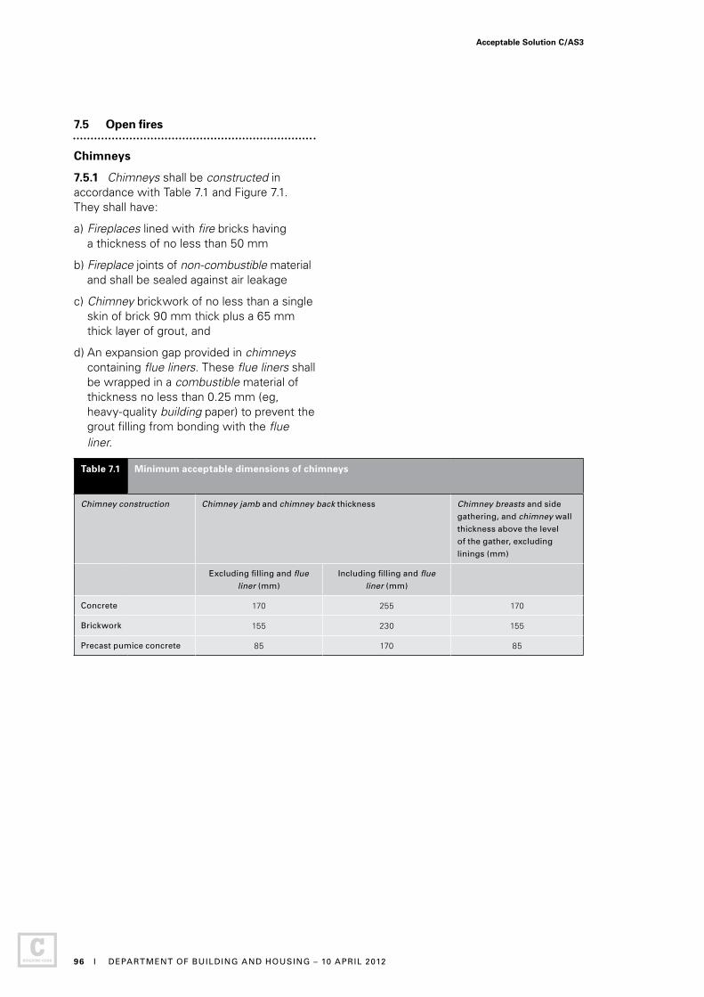
7.5 Open fires
Chimneys
7.5.1 Chimneys shall be constructed in accordance with Table 7.1 and Figure 7.1. They shall have:
a) Fireplaces lined with fire bricks having a thickness of no less than 50 mm
b) Fireplace joints of non-combustible material and shall be sealed against air leakage
c) Chimney brickwork of no less than a single skin of brick 90 mm thick plus a 65 mm thick layer of grout, and
d) An expansion gap provided in chimneys containing flue liners. These flue liners shall be wrapped in a combustible material of thickness no less than 0.25 mm (eg, heavy-quality building paper) to prevent the grout filling from bonding with the flue liner.
Table 7.1 Minimum acceptable dimensions of chimneys
Chimney construction Chimney jamb and chimney back thickness Chimney breasts and side
gathering, and chimney wall
thickness above the level
of the gather, excluding
linings (mm)
Excluding filling and flue
liner (mm)
Including filling and flue
liner (mm)
Concrete 170 255 170
Brickwork 155 230 155
Precast pumice concrete 85 170 85
Acceptable Solution C/AS3
96 I DEPARTMENT OF BUILDING AND HOUSING – 10 APRIL 2012
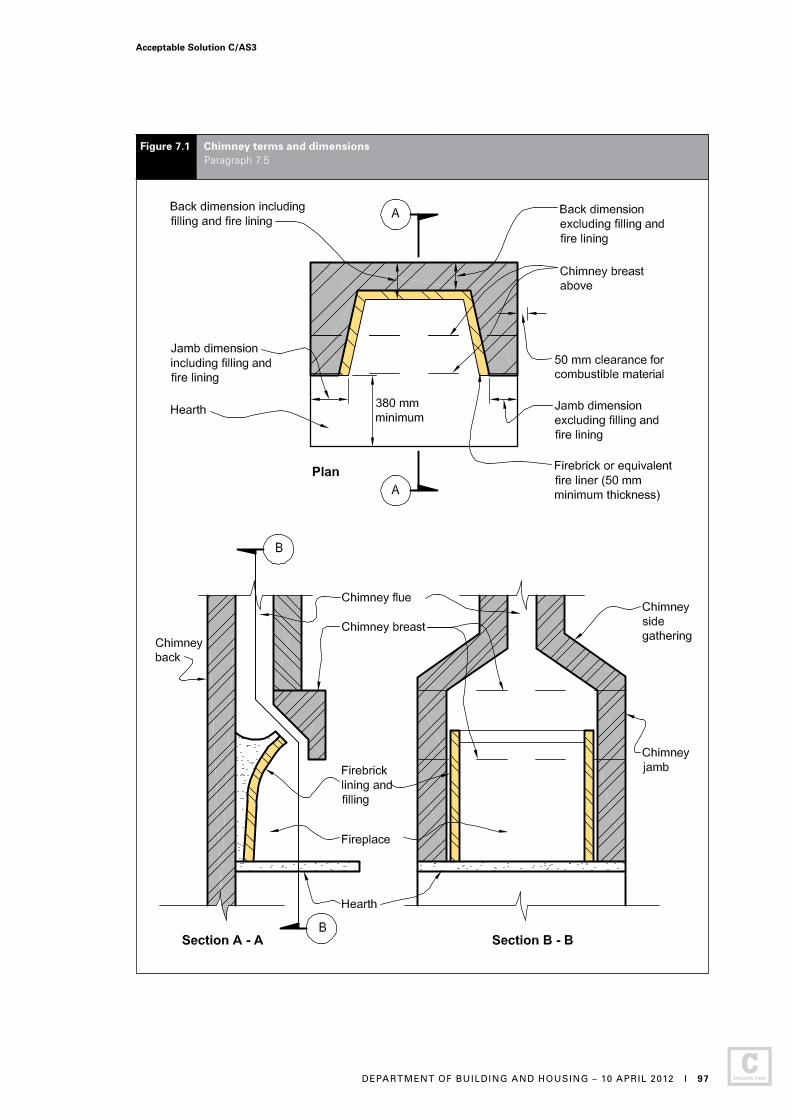
Figure 7.1 Chimney terms and dimensions Paragraph 7.5
Acceptable Solution C/AS3
DEPARTMENT OF BUILDING AND HOUSING – 10 APRIL 2012 I 97
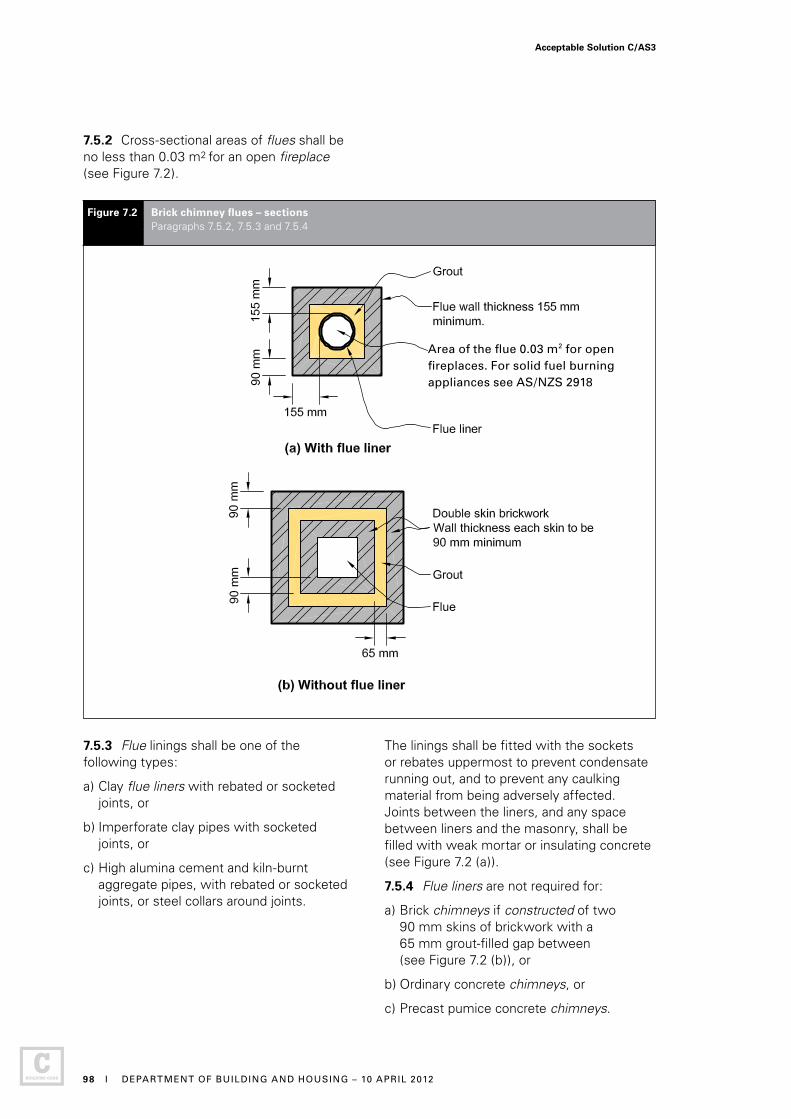
7.5.2 Cross-sectional areas of flues shall be no less than 0.03 m2 for an open fireplace (see Figure 7.2).
7.5.3 Flue linings shall be one of the following types:
a) Clay flue liners with rebated or socketed joints, or
b) Imperforate clay pipes with socketed joints, or
c) High alumina cement and kiln-burnt aggregate pipes, with rebated or socketed joints, or steel collars around joints.
The linings shall be fitted with the sockets or rebates uppermost to prevent condensate running out, and to prevent any caulking material from being adversely affected. Joints between the liners, and any space between liners and the masonry, shall be filled with weak mortar or insulating concrete (see Figure 7.2 (a)).
7.5.4 Flue liners are not required for:
a) Brick chimneys if constructed of two 90 mm skins of brickwork with a 65 mm grout-filled gap between (see Figure 7.2 (b)), or
b) Ordinary concrete chimneys, or
c) Precast pumice concrete chimneys.
Figure 7.2 Brick chimney flues – sections Paragraphs 7.5.2, 7.5.3 and 7.5.4
Area of the flue 0.03 m2 for open fireplaces. For solid fuel burning appliances see AS/NZS 2918
Acceptable Solution C/AS3
98 I DEPARTMENT OF BUILDING AND HOUSING – 10 APRIL 2012
7.5.5 Clearance above roofs shall be in accordance with Figure 4.9 of AS/NZS 2918.
7.5.6 Every fireplace shall have a separate flue.
7.5.7 Flue joints shall be of non-combustible material and sealed against air leakage.
7.5.8 Hearths for fireplaces shall:
a) Be constructed of fully grouted stones, bricks or concrete of no less than 50 mm total thickness
b) Extend no less than 230 mm on each side of the fireplace opening, and no less than 380 mm forward of the fireplace opening, and
c) Have no combustible material closer than the clearances given in Paragraph 7.5.8 b) from the upper and lower surfaces of the hearth.
7.5.9 Clearances between a chimney and any combustible material (see Figure 7.3) shall be no less than:
a) 200 mm at any opening in the flue, or at the fireplace opening, and
b) 200 mm above or below the upper surface of the hearth, and 75 mm from the lower surface of the hearth.
7.5.10 Hearth edges are to be separated from combustible material with insulating material having a minimum service operating temperature of 150°C.
Comment:AS/NZS 2918 Appendix C gives a test method for heat-resistant and heat-tolerant materials.
7.5.11 A ventilated space of no less than 50 mm shall be provided between the outer face of a fireplace, chimney or flue and any combustible material.
7.5.12 AS/NZS 2918 Sections 2 and 4 are also Acceptable Solutions for the installation of flues from open fires.
Acceptable Solution C/AS3
DEPARTMENT OF BUILDING AND HOUSING – 10 APRIL 2012 I 99

Figure 7.3 Clearances between a chimney and hearth, and combustible materials Paragraph 7.5.9
Acceptable Solution C/AS3
100 I DEPARTMENT OF BUILDING AND HOUSING – 10 APRIL 2012

A1.1 Fire alarm and sprinkler systems
A1.1.1 Fire alarm systems used in fire safety systems shall satisfy the requirements of Acceptable Solution F7/AS1. Fire sprinkler systems used in the fire safety systems shall, except where specified, also satisfy the requirements of Appendix B.
A1.2 Requirements common to alarm systems
A1.2.1 Except for domestic smoke alarm systems and, where otherwise specified, each fire alarm system, regardless of method of activation, shall be provided with a means of communication with the Fire Service in accordance with Acceptable Solution F7/AS1.
A2.1 Fire safety system descriptions
A2.1.1 The following text provides a brief description of fire safety systems not otherwise described in Acceptable Solution F7/AS1. See F7/AS1 for descriptions of fire alarm systems Types 1, 2, 3, 4, 5, 6 and 7.
Type 9 – Smoke control in air handling systems
Where smoke control is required in relation to heating, ventilating or air conditioning systems, it shall comply with the requirements of either:
a) AS/NZS 1668: Part 1 and interface with any Type 4 or 7 system installed if it is self contained detection, control and provision of output signal/alarm, or
b) NZS 4512 to provide ancillary function output for control of the HVAC system if a Type 4 or 7 alarm system is used as a means of smoke detection.
Type 18 – Fire hydrant systems for buildings
Fire hydrant systems shall comply with NZS 4510.
Appendix A (normative): Fire safety systems
Acceptable Solution C/AS3 – Appendices
DEPARTMENT OF BUILDING AND HOUSING – 10 APRIL 2012 I 101
B1.1 Introduction
B1.1.1 Wherever sprinklers are required by this Acceptable Solution, they shall comply with the relevant New Zealand Standard, amended as shown in Paragraphs B2.1 and B3.1.
B2.1 Automatic fire sprinkler systems
B2.1.1 NZS 4541 is amended as follows:
Clause 103 Definitions
Sprinkler system A system including:
(a) to (i) No change.
(j) Delete.
(k) Delete.
(l) No change.
Clause 205 Delete entire clause.
Clause 209 Delete entire clause.
Clause 1203 Routine Surveys
Clause 1203.1 Delete first two paragraphs and replace with:
“It is important that a sprinkler system at all times complies with this Standard as amended by Paragraph B2.1 of Appendix B to C/AS3 in all respects. To ensure that building alterations, changes in process or storage patterns or progressive deterioration of system components do not prejudice system compliance, a comprehensive survey shall be carried out biennially at intervals not exceeding 28 months. Such surveys shall be carried out by an independent qualified person.”
Appendix B (normative): Fire sprinkler systems
B3.1 Residential fire sprinkler systems
B3.1.1 NZS 4515 is amended as follows:
Clause 1.5 Definitions
Sprinkler system A system including:
(a) to (g) No change.
(h) Delete.
Clause 1.11 Delete entire clause.
Clause 2.1.2 Delete.
Clause 2.1.3 Delete.
Amend 2Dec 2013
Amend 2Dec 2013
Acceptable Solution C/AS3 – Appendices
102 I MINISTRY OF BUSINESS, INNOVATION AND EMPLOYMENT – 19 DECEMBER 2013

C1.1 General
This Appendix contains test methods for confirming that specific building elements satisfy relevant provisions of the Acceptable Solutions for Protection from Fire. It includes both established standard tests and other test methods for building elements in situations where standard tests are unavailable.
Comment: Regardless of the year of the Standard incorporated by reference in this Acceptable Solution, there is no intention to require the building elements listed here to be retested to the current edition of the relevant Standard when they have previously been tested to an earlier version of that Standard in force at the date of testing.
C2.1 Flammability of floor coverings
Materials shall be assigned a critical radiant flux when tested to:
ISO 9239 Reaction to fire tests for flooring – Part 1: Determination of the burning behaviour using a radiant heat source.
Or in lieu of testing refer to Table B1 of Appendix B in C/VM2.
C3.1 Flammability of suspended flexible fabrics and membrane structures
Materials shall be assigned a flammability index when tested to:
AS 1530 Methods for fire tests on building materials and structures – Part 2: Test for flammability of materials.
C4.1 Properties of lining materials
C4.1.1 Combustibility test
Materials shall be classified as non-combustible or combustible when tested to:
AS 1530 Methods for fire tests on building materials and structures – Part 1: Combustibility test for materials
Appendix C (normative): Test methods
C4.1.2 Material for internal surface linings shall be given a Group Number in accordance with Appendix A of C/VM2 and tested to either:
ISO 5660 Reaction-to-fire tests Part 1 Heat release rate (cone calorimeter method), and Part 2 Smoke production rate (dynamic method), or
ISO 9705 Fire tests – Full scale room test for surface products.
Or in lieu of testing refer to Table A1 of Appendix A in C/VM2.
C5.1 Fire resistance
C5.1.1 Primary and secondary elements, closures and fire stops shall be assigned a fire resistance rating (FRR) when tested to:
a) AS 1530 Methods for fire tests on building materials and structures – Part 4: Fire resistance tests of elements of building construction, or
b) NZS/BS 476 Fire tests on building materials and structures – Parts 21 and 22.
C5.1.2 Fire stops shall be tested:
a) In circumstances representative of their use in service, paying due regard to the size of expected gaps to be fire stopped, and the nature of the fire separation within which they are to be used, and
b) In accordance with AS 4072: Components for the protection of openings in fire-resistent separating elements – Part 1: Service penetrations and control joints.
C6.1 Fire doors and smoke control doors
C6.1.1 Fire doors shall be evaluated in circumstances representative of their use in service, and shall comply with NZS 4520: Fire-resistant doorsets.
Amend 3 Jul 2014
Amend 3 Jul 2014
Errata 1Feb 2013
Acceptable Solution C/AS3 – Appendices
MINISTRY OF BUSINESS, INNOVATION AND EMPLOYMENT – 1 JULY 2014 I 103
Errata 1Feb 2013
Amend 3Jul 2014
Smoke control doors
C6.1.2 A door shall be deemed to be a smoke control door if, in addition to the requirements in this Acceptable Solution for smoke control doors:
a) The door is a fire door that is fitted with appropriate smoke seals, or if:
b) It is constructed with solid core leaves. Solid timber core leaves, when used, shall have a leaf thickness of no less than 35 mm, and
c) It is provided with smoke seals as required by this Acceptable Solution. Smoke seals shall be in continuous contact with the mating element, and located so as to minimise interruption by hardware, and
d) The frames are constructed of timber, and the jambs are no less than 30 mm thick, and
e) Any vision panel cut-outs are no less than 150 mm from the leaf edges, and
f) The maximum average clearances (excluding pre-easing) are:
i) Leaf to frame 3 mm
ii) Leaf to leaf 5 mm
iii) Leaf to top of any floor covering 10 mm, and
g) If there are additional facings, they shall be adhesive fixed, and
h) It is provided with signage identifying it as a smoke control door in accordance with Acceptable Solution F8/AS1.
Frictional forces
C6.1.3 The forces required to open any fire door or smoke control door on an escape route, shall not exceed 67 N to release the latch, 133 N to set the door in motion, and 67 N to open the door to the minimum required width. These forces shall be applied at the latch stile. These requirements do not apply to horizontal sliding doors in risk group SI or to power-operated doors.
Self-closing provision
C6.1.4 All fire and smoke control door leaves shall be self-closing, and provision shall be made for the self-closing device to be adjustable during commissioning to satisfy the requirements of Paragraph C6.1.3 after installation.
C6.1.5 Where it is desirable in normal circumstances for a fire door or smoke control door to operate freely, it is acceptable to use a self-closer mechanism which activates in the event of fire but does not operate at other times.
Comment:1. These circumstances can occur where people are
under care. Leaving the door to the occupant’s room (or suite ) open reduces that occupant’s feeling of isolation and permits ready observation by staff.
2. Self-closers can be an obstruction to the elderly and people with disabilities, who may have difficulty in opening the door against the pressure applied by the self-closer. Acceptable Solution C/AS3 Paragraph 4.6 describes situations where smoke control doors do not have to be self-closing where they are used within a group sleeping area or suite.
Automatic smoke-sensing devices
C6.1.6 Automatic smoke-sensing devices complying with NZS 4512, if used, shall be positioned within the stream of air that passes the door when the smoke control door is fully open.
C7.1 Fire properties of external wall cladding systems
C7.1.1 Fire properties of external wall cladding systems shall be determined in accordance with:
ISO 5660 Reaction-to-fire tests – Heat release, smoke production and mass loss rate – Part 1: Heat release rate (cone calorimeter method).
C7.1.2 In addition to meeting the general requirements of ISO 5660 Part 1, testing shall be in accordance with the following specific requirements:
a) An applied external heat flux of 50 kW/m2, and
b) A test duration of 15 minutes, and
c) The total heat release measured from start of the test, and
d) Sample orientation horizontal, and
e) Ignition initiated by the external spark igniter.
Amend 2 Dec 2013
Amend 2 Dec 2013
Acceptable Solution C/AS3 – Appendices
104 I MINISTRY OF BUSINESS, INNOVATION AND EMPLOYMENT – 19 DECEMBER 2013
C7.1.3 Timber claddings which have a fire retardant treatment incorporated in or applied to them shall be subjected to the regime of accelerated weathering described by ASTM D 2898 Method B with the water flow rate from Method A, before testing in accordance with the requirements of Paragraph C7.1.1.
C7.1.4 External wall cladding systems, which comprise only materials which individually are classified as non-combustible, may be deemed to satisfy all the requirements of Paragraph 5.8.1.
Comment:The non-combustible classification represents a more onerous performance level than those required by Paragraph 5.8.1 and is therefore acceptable. A non-combustible classification may be claimed only if the respective materials have been subjected to testing as described in Paragraph C7.1.1.
C7.1.5 Claddings incorporating a metal facing with a melting point of less than 750°C covering a combustible core or insulant shall be tested as described in Paragraph C7.1.2 without the metal facing present.
Comment:Aluminium has a melting point of less than 750°C.
Acceptable Solution C/AS3 – Appendices
DEPARTMENT OF BUILDING AND HOUSING – 10 APRIL 2012 I 105
Index
Alterations and changes of use . . . . . . . . . . . . . . . . . . . . . . . . . . 1.3
Control of external fire spread. . . . . . . . . . . . . . . . . . . . . . . . . Part 5 External walls – table method. . . . . . . . . . 5.5, Figures 5.2 and 5.3, Tables 5.2 and 5.3 Exterior surface finishes . . . . . . . . . . . . . . . . . . . . . . . . . . . . . . . 5.8 External walls . . . . . . . . . . . . . . . . . . . . . . . . . 5.8.1, 5.8.2, 5.8.4 Fire separation for buildings with more than one title . . . . . . . . 5.1 FRRs of external walls 5.3 Small openings and fire resisting glazing . . . . . . .5.4, Figure 5.1, Table 5.1 Horizontal fire spread from external walls. . . . . . . . . . . . . . . . . . 5.2 Separation . . . . . . . . . . . . . . . . . . . . . . . . . . . 5.2.1, 5.2.2, 5.2.3, 5.2.4, 5.2.5, 5.2.6 Analysis required for all external walls . . . . . . . . . . . . . .5.2.7 Notional boundary – firecells on the same property. . . 5.2.8, 5.2.9 Horizontal fire spread from roofs and open-sided buildings . . . . 5.6 Open sided buildings . . . . . . . . . . . . . . . .5.6.6, 5.6.7, Figure 5.5 Parapets for storage. . . . . . . . . . . . . . . . . . . . . . . . . . . . . . .5.6.2 Roof projections . . . . . . . . . . . . . . 5.6.3, 5.6.4, 5.6.5, Figure 5.4 Vertical fire spread. . . . . . . . . . . . . . . . . . . . . . . . . . . . . . . . . . . . 5.7 Different levels of the same building . . 5.7.10, 5.7.11, Figure 5.7 External thermal insulation – multi-storey buildings . . . . .5.7.17, 5.7.18, Figure 5.8 Roofs . . . . . . . . . . . . . . . . . . . . . . . . . . . . . . . . . . . . . 5.7.1, 5.7.2 External exitways over roofs. . . . . . . . . . . . . . . . . . . . . . 5.7.3 Fire spread from an adjacent lower roof . . .5.7.6, 5.7.7, 5.7.8, 5.7.9, Figure 5.6 Primary elements . . . . . . . . . . . . . . . . . . . . . . . . . 5.7.4, 5.7.5 Roof storage . . . . . . . . . . . . . . . . . . . . . . . . . . . . . . . . . 5.7.16 Spandrels and apron projections . . . . . . . . 5.7.12, 5.7.13, 5.7.14, 5.7.15, Table 5.4
Control of internal fire and smoke spread . . . . . . . . . . . . . . . Part 4 Building services plant . . . . . . . . . . . . . . . . . . . . . . . . . . . . . . . 4.18 Air handling systems . . . . . . . . . . . . . . . . . . . . . . . . . . . . .4.18.2 Automatic activation. . . . . . . . . . . . . . . . . . . . . . . . . . . . . . 4.18.1 Closures in fire and smoke separations . . . . . . . . . . . . . . . . . . 4.16 Doorset markings. . . . . . . . . . . . . . . . . . . . . . . . . . 4.16.5, 4.16.6 Fire door and smoke door installation . . . . . . . . . . . . . . . .4.16.4 Fire doors . . . . . . . . . . . . . . . . . . 4.16.9, Figures 4.14, 4.15, 4.16 Glazing . . . . . . . . . . . . . . . . . . . . . . . . . . . . . . . . . . . . . . . . 4.16.7 Lift landing doors . . . . . . . . . . . . . . . . . . . . . . . . . . . . . . . 4.16.11 Introduction . . . . . . . . . . . . . . . . . . . . . . . . 4.16.1, 4.16.2, 4.16.3 Protected shaft access panels . . . . . . . . . . . 4.16.10, Figure 4.17 Smoke control doors . . . . . . 4.16.8, Figures 4.12, 4.13 and 4.14
References are to the relevent paragraphs, figures or tables in C/AS3 unless otherwise stated. References to Appendices are prefixed by the Appendix letter.
Index C/AS3
106 I DEPARTMENT OF BUILDING AND HOUSING – 10 APRIL 2012

Control of internal fire and smoke spread continued Concealed spaces . . . . . . . . . . . . . . . . . . . . . . . . . . . . . . . . . . . 4.15 Cavity barriers in walls and floors .4.15.3, Figures 4.10 and 4.11 Construction. . . . . . . . . . . . . . . . . . . . . . . . . . . . . . . . . . . . 4.15.5 Exceptions . . . . . . . . . . . . . . . . . . . . . . . . . . . . . . . . . . . . . 4.15.4 Within firecells . . . . . . . . . . . . . . . . . . . . . . . . .4.15.2, Figure 4.9 Exitways . . . . . . . . . . . . . . . . . . . . . . . . . . . . . . . . . . . see Exitways Firecells . . . . . . . . . . . . . . . . . . . . . . . . . . . . . . . . . . . . .see Firecells Fire stopping . . . . . . . . . . . . . . . . . . . . . . . . . . . . . . . . . . . . . . . . 4.4 Fire stops . . . . . . . . . . . . . . . . . . . . . . . . . . . . 4.4.2, 4.4.3, 4.4.4 Introduction . . . . . . . . . . . . . . . . . . . . . . . . . . . . . . . . . . . . .4.4.1 Fire dampers . . . . . . . . . . . . . . . . . . . . . . . . . . . . . . . . . . . . . 4.16.12 Fire shutters . . . . . . . . . . . . . . . . . . . . . . . .4.16.13, 4.16.14, 4.16.15 Floors . . . . . . . . . . . . . . . . . . . . . . . . . . . . . . . . . . . . . . . . . . . . 4.13 Basement floors. . . . . . . . . . . . . . . . . . . . . . . . . . . . . . . . . 4.13.9 Intermediate floors . . . . . . . . . . . . . . . . . . . 4.13.4, 4.13.5, 4.13.6 Glazing in fire and smoke separations. . . . . . . . . . . . . . . . . . . . . 4.2 Fire doors and smoke control doors . . . . . . . . . . . . 4.2.4, 4.2.5 Interior surface finishes, floor coverings and suspended flexible fabrics . . . . . . . . . . . . . . . . 4.17.1, Table 4.1 Air ducts . . . . . . . . . . . . . . . . . . . . . . . . . . . . . . . . . . . . . . 4.17.11 Exceptions . . . . . . . . . . . . . . . . . . . . . . . . . . . . . . . . . . . . . 4.17.6 Combustible insulating materials . . . . . . . . . . . . . . . . . . . . 4.17.2 Flooring. . . . . . . . . . . . . . . . . . . . . . . . . . 4.17.3, 4.17.4, Table 4.2 Wood and wood panel products. . . . . . . . . . . . . . . . . . 4.17.5 Foamed plastics . . . . . . . . . . . . . . . . . . . . . . . . . . . . . . . . . 4.17.2 Suspended flexible fabrics . . . . . . . . . . . . . . . . . . . . . . . . . 4.17.8 Intermittent activities . . . . . . . . . . . . . . . . . . . . . . . . . . . . . . . . 4.10 Plant, boiler and incinerator rooms . . .4.10.3, 4.10.4, Figure 4.5 Solid waste storage . . . . . . . . . . . . . . . . . . . . . . . . . . . . . .4.10.2 Long corridor subdivision . . . . . . . . . . . . . . . . . . . . 4.12, Figure 4.7 Protected shafts . . . . . . . . . . . . . . . . . . . . . . . . . . . 4.11, Figure 4.6 Access panels . . . . . . . . . . . . . . . . . . . . . . . . . . . . . . . . . 4.16.11 Fire separation . . . . . . . . . . . . . . . . . . . . . . . . . . . . 4.11.2, 4.11.3 Lifts, conveyors and services. . . . . . . . . . . . . . . . . . . . . . . 4.11.1 Openings . . . . . . . . . . . . . . . . . . . . . . . . . . . . . . . . . . . . . . 4.11.4 Solid waste and linen chutes . . . . . . . . . . . . . . . . . 4.11.5, 4.11.6 Specific requirements for sleeping areas . . . . . . . . . . . . . . . . . . 4.6 Group sleeping areas . . . . . . . . . . . . . . . . . . . . . . . . 4.6.3, 4.6.4 Special care facilities . . . . . . . . . . . . . . . . . . . . . . . . . . . . . .4.6.6 Suites . . . . . . . . . . . . . . . . . . . . . . . . . . . . . . . . . . . . . . . . . .4.6.5 Support and service functions . . . . . . . . . . . . 4.6.7, 4.6.8, 4.6.9 Structural stability during fire . . . . . . . . . . . . . . . . . . . . . . . . . . . 4.3 Building elements with an FRR . . . . . . . . . . . . . . . . .4.3.1, 4.3.2 Horizontal stability . . . . . . . . . . . . . . . . . . . . . . . . . . . . . . . .4.3.5 Unrated primary elements . . . . . . . . . . . . . . . . .4.3.3, Figure 4.1 Vertical stability . . . . . . . . . . . . . . . . . . . . . . . . . . . . . . . . . .4.3.4 Subfloor spaces. . . . . . . . . . . . . . . . . . . . . . . . . . . . 4.14, Figure 4.8
Amend 3 Jul 2014
Index C/AS3
MINISTRY OF BUSINESS, INNOVATION AND EMPLOYMENT – 1 JULY 2014 I 107
Escape routes Dead ends . . . . . . . . . . . . . . . . . . . . . . . . . . . . . . . . . . . . . . . . . . 3.8 No more than 50 occupants . . . . . . . . . . . . . . . . . . . . . . . .3.8.1 Doors subdividing escape routes . . . . . . . . . . . . . . . . . . . . . . . 3.15 Access control systems . . . . . . . . . . . . . . . . . . . . . . . . . . . 3.15.7 Automatic doors. . . . . . . . . . . . . . . . . 3.15.7, 3.15.8, Figure 3.24 Degree and width of opening . . . 3.15.5, Figures 3.22 and 3.23 Delayed action unlocking devices . . . . . . . . . . . . . . . . . . 3.15.11 Direction of opening. . . . . . . . . . . . . . . . . . . . . . . . 3.15.3, 3.15.4 Hold-open devices . . . . . . . . . . . . . . . . . . . . . . . . 3.15.9, 3.15.10 Locking devices . . . . . . . . . . . . . . . . . . . . . . . . . . . . . . . . .3.15.2 Revolving doors . . . . . . . . . . . . . . . . . 3.15.7, 3.15.8, Figure 3.24 Simple fastenings. . . . . . . . . . . . . . . . . . . . . . . . . . . . . . . 3.15.14 Vision panels . . . . . . . . . . . . . . . . . . . . . . . . . . . . . . . . . . . 3.15.6 Escape through adjoining building. . . . . . . . . . . . .3.4.6, Figure 3.10 Escape from basements . . . . . . . . . . . . . . . . . . . . . . . . . . . . . . . 3.5 Exitways . . . . . . . . . . . . . . . . . . . . . . . . . . . . . . . . . . . see Exitways External escape routes . . . . . . . . . . . . . . . . . . . . . . . . . . . . . . . 3.11 Balconies or bridges. . . . . . . . . . . . . . . . . . . . 3.11.6, Figure 3.19 Ventilation openings . . . . . . . . . . . . . . . . . . . . . . . . . . . 3.11.7 Barriers. . . . . . . . . . . . . . . . . . . . . . . . . . . . . . . . . . . . . . . . 3.11.8 Separation by distance. . . . . . . . . . . 3.11.2, 3.11.3, 3.11.4, 3.11.5 Separation by fire rated construction . . . . . . . . . . . . . . . . . 3.11.6 Height and width. . . . . . . . . . . . . . . . . . . . . . . . . . . . . . . . . . . . . 3.3 Curved and spiral stairs . . . . . . . . . . . . . . . . . . . . . . . . . . . .3.3.5 Handrails and limitation to stairway widths . . . . . . . 3.3.3, 3.3.4, Figure 3.6 Height. . . . . . . . . . . . . . . . . . . . . . . . . . . . . . . . . . . . . . . . . .3.3.1 Obstructions. . . . . . . . . . . . . . . . . . . . . . . . . . . . . . . . . . . . .3.3.6 Width . . . . . . . . . . . . . . . . . . . . . . . . . . . . 3.3.2, Figures 3.4, 3.5 Length . . . . . . . . . . . . . . . . . . . . . . . . . . . . . . . . . . . . . . . . . . . . . 3.4 Intermediate floors . . . . . . . . . . . . . . . . . . . . . . 3.4.3, Figure 3.8 Open paths. . . . . . . . . . . . . . . . . . . . 3.4.2, Figure 3.7, Table 3.2 Stairs and ladders. . . . . . . . . . . . . . . . . . . . . . . 3.4.4, Figure 3.9 Number of escape routes . . . . . . . . . . . . . . . . . . . . . . 3.2, Table 3.1 Open paths . . . . . . . . . . . . . . . . . . . . . . . . . . . . . . see Open paths Safe paths . . . . . . . . . . . . . . . . . . . . . . . . . . . . . . . . .see Safe paths Signs . . . . . . . . . . . . . . . . . . . . . . . . . . . . . . . . . . . . . . . . . . . . 3.16 Width . . . . . . . . . . . . . . . . . . . . . . . . . . . . . . see Height and width
Exitways . . . . . . . . . . . . . . . . . . . . . . . . . . . . . . . . . . . . . . . . . 3.9, 4.9 Control of exitway activities . . . . . . . . . . . . . . . . . . . . . . . . . . . 3.10 Safe paths . . . . . . . . . . . . . . . . . . . . . . . . . . . . . . . . .see Safe paths Smoke lobbies – floor area . . . . . . . . . . . . . . . . . .3.9.2, Figure 3.16
Firecells . . . . . . . . . . . . . . . . . . . . . . . . . . . . . . . . . . . . . . . Part 2, 4.1 Firecell construction . . . . . . . . . . . . . . . . . 4.5.1, 4.5.2, 4.5.3, 4.5.4 Ceiling space firecells. . . . . . . . . . . . . . . . . . . . . . . . . . . . . .4.5.8 Junctions of fire separations . . 4.5.5, 4.5.6, Figures 4.2 and 4.3 Junctions with roof . . . . . . . . . . . . . . . . . . . . . . . . . . . . . . .4.5.7 Sealing of gaps. . . . . . . . . . . . . . . . . . . . . . . . . . . . .4.5.9, 4.5.10
Index C/AS3
108 I DEPARTMENT OF BUILDING AND HOUSING – 10 APRIL 2012
Firecells continued Fire safety systems . . . . . . . . . . . . . . . . . . 2.2, Table 2.1, Figure 2.1 Floor with more than one risk group . . . . . . . 2.2.4, 2.2.5, 2.2.6 Other floors in a building . . . . . . . . . . . . . . . . . . . . . . . . . . .2.2.7 Same risk group on different floors . . . . . . . . . . . . . . . . . . .2.2.8 Floor area limits. . . . . . . . . . . . . . . . . . . . . . . . . . . . . . . . . . . . . 2.1.1 Passing into an adjacent firecell . . . . . . . . . . . . . 3.7.13, Figure 3.15 Provision . . . . . . . . . . . . . . . . . . . . . . . . . . . . . . . . . . . . . . . . . . . 2.1
Firefighting . . . . . . . . . . . . . . . . . . . . . . . . . . . . . . . . . . . . . . . . . Part 6 Access for firefighting and rescue operations. . . . . . . . . . . . . . . 6.3 Firefighting facilities. . . . . . . . . . . . . . . . . . . . . . . . . . . . . . . . . . . 6.4 Fire hydrant system . . . . . . . . . . . . . . . . . . . . . . . . . .6.4.1, 6.4.2 Fire Service lift control . . . . . . . . . . . . . . . . . . . . . . . . . . . . 6.4.3 Fire Service vehicular access . . . . . . . . . . . . . . . . . . . . . . . . . . . 6.1 Information for firefighters . . . . . . . . . . . . . . . . . . . . . . . . . . . . . 6.2
Fire resistance ratings. . . . . . . . . . . . . . . . . . Part 2, 2.3, 2.3.1, 2.3.3 Insulation component . . . . . . . . . . . . . . . . . . . . . . . . . . . . . . . 2.3.13 General requirements . . . . . .2.3.4, 2.3.5, 2.3.6, 2.3.7, 2.3.8, 2.3.9, 2.3.10, 2.3.11
Fire safety systems . . . Part 2, 2.2, Table 2.1, Figure 2.1, Appendix A Fire alarm and sprinkler systems . . . . . . . . . . . . . . . . . . . . . . A1.1.1 Fire safety system descriptions . . . . . . . . . . . . . . . . . . . . . . . . A2.1 Floor with more than one risk group. . . . . . . . . . 2.2.4, 2.2.5, 2.2.6 Other floors in a building. . . . . . . . . . . . . . . . . . . . . . . . . . . . . .2.2.7 Same risk group on different floors . . . . . . . . . . . . . . . . . . . . .2.2.8 Requirements common to alarm systems . . . . . . . . . . . . . . . . A1.2
Fire sprinkler systems . . . . . . . . . . . . . . . . . . . . . . . . . . . Appendix B Automatic fire sprinkler systems. . . . . . . . . . . . . . . . . . . . . . . . B2.1 Introduction . . . . . . . . . . . . . . . . . . . . . . . . . . . . . . . . . . . . . . . . B1.1 Residential fire sprinkler systems . . . . . . . . . . . . . . . . . . . . . . . B3.1
General . . . . . . . . . . . . . . . . . . . . . . . . . . . . . . . . . . . . . . . . . . . Part 1 Scope . . . . . . . . . . . . . . . . . . . . . . . . . . . . . . . . . 1.1, 1.1.1, Table 1.1 Hazardous substances . . . . . . . . . . . . . . . . . . . . . . . . . . . . . 1.1.5 Outside the scope . . . . . . . . . . . . . . . . . . . . . . . . . . . . . . . . 1.1.2 Using this Acceptable Solution . . . . . . . . . . . . . . . . . . . . . . . . . . 1.2 Primary risk groups . . . . . . . . . . . . . . . . . . . . . . . . . .1.2.2, 1.2.3
Means of escape . . . . . . . . . . . . . . . . . . . . . . . . . . . . . . . . . . . . Part 3 Escape routes . . . . . . . . . . . . . . . . . . . . . . . . . . See Escape routes General principles . . . . . . . . . . . . . . . . . . . . . . . . . . . 3.1, Figure 3.1
Occupant loads . . . . . . . . . . . . . . . . . . . . . . . . . . . . . . 1.4, Figure 1.1 Risk group SI . . . . . . . . . . . . . . . . . . . . . . . . . . . . . . . . . . . . . . .1.4.4 Occupant densities . . . . . . . . . . . . . . . . . . . . . . . . . .1.4.2, Table 1.2
Open paths . . . . . . . . . . . . . . . . . . . . . . . . . . . . . . . . . . . . . . . . . . . 3.6 Length . . . . . . . . . . . . . . . . . . . . . . . . . . 3.4.2, Figure 3.7, Table 3.2 Passing into an adjacent firecell . . . . . . . . . . . . . 3.7.13, Figure 3.15 Separation . . . . . . . . . . . . . . . . . . . . . . . . . . . . . . .3.6.2, Figure 3.12 Special cases. . . . . . . . . . . . . . . . . . . . . . . . . . . . . . . . . . . . . . . . 3.7 Ramps . . . . . . . . . . . . . . . . . . . . . . . . . . . . . . . . . . . . . . . . . 3.7.1
Index C/AS3
DEPARTMENT OF BUILDING AND HOUSING – 10 APRIL 2012 I 109
Prevention of fire occurring . . . . . . . . . . . . . . . . . . . . . . . . . . . Part 7 Downlights . . . . . . . . . . . . . . . . . . . . . . . . . . . . . . . . . . . . . . . . . 7.4 Gas burning appliances . . . . . . . . . . . . . . . . . . . . . . . . . . . . . . . . 7.2 Modifications for NZS 5261 . . . . . . . . . . . . . . . . . . . . . . . . .7.2.2 Oil-fired appliances . . . . . . . . . . . . . . . . . . . . . . . . . . . . . . . . . . . 7.3 Modifications to AS 1691. . . . . . . . . . . . . . . . . . . . . . . . . . .7.3.2 Open fires . . . . . . . . . . . . . . . . . . . . . . . . . . . . . . . . . . . . . . . . . . 7.5 Chimneys . . . . . . . . . 7.5.1, 7.5.2, 7.5.3, 7.5.4, 7.5.5, 7.5.6, 7.5.7, 7.5.8, 7.5.9, 7.5.10, 7.5.11, 7.5.12, Figures 7.1, 7.2 and 7.3, Table 7.1 Solid fuel appliances . . . . . . . . . . . . . . . . . . . . . . . . . . . . . . . . . . 7.1 Modifications for AS/NZS 2918 . . . . . . . . . . . . . . . . . . . . . . 7.1.2
Risk groups. . . . . . . . . . . . . . . . . . . . . . . . . . . . . . . . . . . . . . . . . . 1.1.2 Floor with more than one risk group. . . . . . . . . . 2.2.4, 2.2.5, 2.2.6 Same risk group on different floors . . . . . . . . . . . . . . . . . . . . .2.2.8 Primary risk groups . . . . . . . . . . . . . . . . . . . . . . . . . . . . . . . . . .1.2.2
Safe paths . . . . . . . . . . . . . . . . . . . . . . . . . . . . . . . . 3.9.4, 3.9.5, 3.9.6 Length restrictions . . . . . . . . . . . . . . . . . . . . . . . . . 3.9.7, Table 3.4 Lifts . . . . . . . . . . . . . . . . . . . . . . . . . . . . . . . . . . . . . 3.10.3, 3.10.4 Separation, glazing and smoke separation . . . . . . . . . .3.9.9. 3.9.10 Special conditions for risk group SI. . . . . . . . . . . . . . . . . . . . . 3.9.11 Termination . . . . . . . . . . . . . . . . . . . . . . . . . . . . . . . . . . . . . . . .3.9.8
Test methods . . . . . . . . . . . . . . . . . . . . . . . . . . . . . . . . . . Appendix C Fire doors and smoke control doors . . . . . . . . . . . . . . . . . . . . . C6.1 Automatic smoke-sensing devices . . . . . . . . . . . . . . . . . .C6.1.6 Frictional forces . . . . . . . . . . . . . . . . . . . . . . . . . . . . . . . . .C6.1.3 Self-closing provision . . . . . . . . . . . . . . . . . . . . . . C6.1.4, C6.1.5 Smoke control doors . . . . . . . . . . . . . . . . . . . . . . . . . . . . .C6.1.2 Fire properties of external wall cladding systems. . . .C7.1.1, C7.1.2, C7.1.3, C7.1.4, C7.1.5 Fire resistance . . . . . . . . . . . . . . . . . . . . . . . . . . . . . . . . . . . . . . C5.1 Flammability of floor coverings . . . . . . . . . . . . . . . . . . . . . . . . . C2.1 Flammability of suspended flexible fabrics and membrane structures. . . . . . . . . . . . . . . . . . . . . . . . . . . . . C3.1 General . . . . . . . . . . . . . . . . . . . . . . . . . . . . . . . . . . . . . . . . . . . C1.1 Properties of lining materials. . . . . . . . . . . . . . . . . . . . . . . . . . . C4.1 Combustibility test . . . . . . . . . . . . . . . . . . . . . . . . . . . . . . .C4.1.1
Index C/AS3
110 I DEPARTMENT OF BUILDING AND HOUSING – 10 APRIL 2012