Embed Size (px)
Citation preview

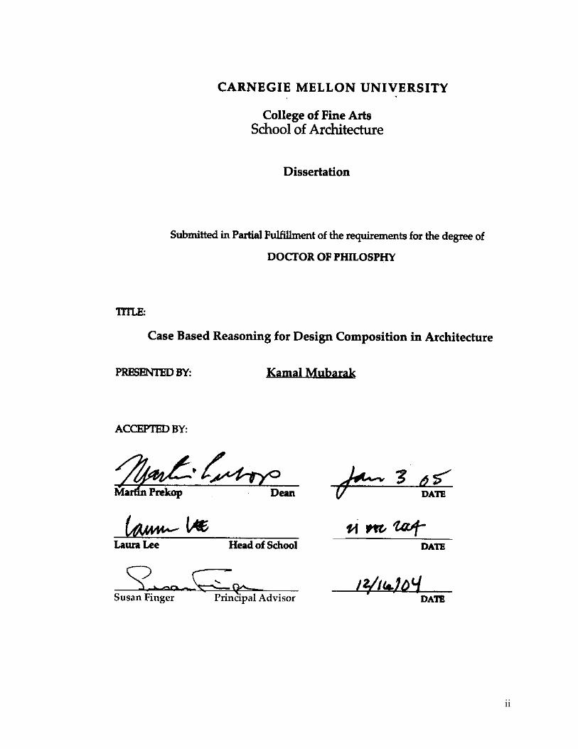
Case Based Reasoning for Design Composition in
Architecture
Dissertation
Kamal Mubarak
Submitted to the School of Architecture of Carnegie Mellon University in partial
fulfillment of the requirement for the degree of Doctor of Philosophy
School of Architecture
Carnegie Mellon University Pittsburgh, Pennsylvania
U.S.A.
December 2004
Advising Committee
Prof. Susan Finger [chair] - Civil Engineering Dept. Prof. Mark Gross – School of Architecture
J. Secosky - R.A. Facilities Management Dept.
ii
iii

iv
Acknowledgement
In the name of GOD, the merciful, the beneficent
Thanks for God “Allah” who blessed me with the ability to finish this thesis and granted
me success in this long-time endeavor “Alhamdullelah”. I would like to dedicate my thesis to my
father, who passed away waiting for this achievement, and to my mother, who encouraged me all
these years. I would like also to thank my brothers and sisters for the inspiration they provided
me.
I would like to express the most sincere gratitude to my chair advisor, Prof. Susan Finger
for believing in me and my work, and sharing with the times of struggle, and guiding me
throughout this endeavor. Also my gratitude is for another wonderful advisor Prof. Mark Gross
who provided me with a wealth of knowledge and guidance particularly at the last months of this
research. Also, I would like to express special thanks to the third member of my advising
committee Mr. Jim Secosky, for his practical and to-the-point advice on many issues in this
research. I would like also to thank Prof. Ulrich Flemming for his valuable advice through out
the time of this work, and I wish him happy retirement.
I cannot explicit the feeling of deep appreciating to my wonderful wife and best friend
Inna, whose love, support and encouragement, and sharing my struggle made my dream come
true. I also devote this success to my lovely daughter Oksana, who by doing her “ABC’s
homework” kept encouraging me to do mine.
My deepest gratitude is for two other great friends, the first is for Ahmed Zakaria, who
gave me support and encouragement in the hardiest days. And the second is for Linda McFadden, who
was my strongest supporter in the whole course of my studying in the USA. She is an example of the
great people of this country.

v
Abstract
This thesis presents a process model for design composition using an abstraction of form and
function characteristics of design solutions. The design process model is based on adapting previous
solutions to generate new designs using derivational analogy. The model relies on a geometric
representation of design compositions. This representation encodes functional and form attributes of
design and is used to build compositional characteristics of the design. The research uses Solution Traces
(Sol-Traces) as constructs for recording and reusing the design composition. The trace consists of
compositional steps. The trace – the sequence of steps - can be replayed to generate design solutions.
Design reasoning with architectural cases has a long history in architecture. Generative case based
reasoning using derivational analogy is a powerful problem solving technique that enables new designs
to be created by utilizing the generative path of prior designs. This technique is adapted for use in
developing a design assistance system for design composition in architecture. Solution Traces (Sol-
Traces) are used within a CBR methodology for a design composition assistant: the TRACE system.
Cases in TRACE include architectural representations such as floor plans, form diagram, function
diagram, and the sequence of design composition steps that lead to a particular solution. The TRACE
system utilizes two strategies, transformations and formative ideas, to generate forms. Cases and their
components are classified and indexed in the case base using both form and function attributes. The
thesis presents three worked examples using the TRACE system.
The main contributions of the research are: the abstraction language for design composition using
the Sol-Traces representation and the process model for design composition using this approach.
Another contribution of the research is the application of the generative CBR, using derivational analogy,
in architectural design composition at the early phases. The research also provides the development of
the TRACE system as a CBR system utilizing the research findings.

vi
Copyright © 2004 by Kamal Mubarak
All rights reserved
vii
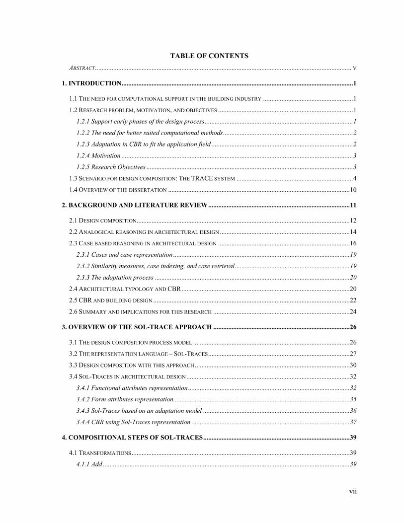
TABLE OF CONTENTS ABSTRACT.......................................................................................................................................................... V
1. INTRODUCTION...........................................................................................................................................1
1.1 THE NEED FOR COMPUTATIONAL SUPPORT IN THE BUILDING INDUSTRY ......................................................1 1.2 RESEARCH PROBLEM, MOTIVATION, AND OBJECTIVES .................................................................................1
1.2.1 Support early phases of the design process.........................................................................................1 1.2.2 The need for better suited computational methods..............................................................................2 1.2.3 Adaptation in CBR to fit the application field .....................................................................................2 1.2.4 Motivation ...........................................................................................................................................3 1.2.5 Research Objectives ............................................................................................................................3
1.3 SCENARIO FOR DESIGN COMPOSITION: THE TRACE SYSTEM ......................................................................4 1.4 OVERVIEW OF THE DISSERTATION .............................................................................................................10
2. BACKGROUND AND LITERATURE REVIEW.....................................................................................11
2.1 DESIGN COMPOSITION................................................................................................................................12 2.2 ANALOGICAL REASONING IN ARCHITECTURAL DESIGN..............................................................................14 2.3 CASE BASED REASONING IN ARCHITECTURAL DESIGN ...............................................................................16
2.3.1 Cases and case representation ..........................................................................................................19 2.3.2 Similarity measures, case indexing, and case retrieval.....................................................................19 2.3.3 The adaptation process .....................................................................................................................20
2.4 ARCHITECTURAL TYPOLOGY AND CBR.....................................................................................................20 2.5 CBR AND BUILDING DESIGN ......................................................................................................................22 2.6 SUMMARY AND IMPLICATIONS FOR THIS RESEARCH ..................................................................................24
3. OVERVIEW OF THE SOL-TRACE APPROACH ..................................................................................26
3.1 THE DESIGN COMPOSITION PROCESS MODEL ..............................................................................................26 3.2 THE REPRESENTATION LANGUAGE – SOL-TRACES.....................................................................................27 3.3 DESIGN COMPOSITION WITH THIS APPROACH.............................................................................................30 3.4 SOL-TRACES IN ARCHITECTURAL DESIGN ..................................................................................................32
3.4.1 Functional attributes representation.................................................................................................32 3.4.2 Form attributes representation..........................................................................................................35 3.4.3 Sol-Traces based on an adaptation model ........................................................................................36 3.4.4 CBR using Sol-Traces representation ...............................................................................................37
4. COMPOSITIONAL STEPS OF SOL-TRACES........................................................................................39
4.1 TRANSFORMATIONS...................................................................................................................................39 4.1.1 Add ....................................................................................................................................................39

viii
4.1.2 Repeat................................................................................................................................................40 4.1.3 Delete ................................................................................................................................................41 4.1.4 Shift ...................................................................................................................................................42 4.1.5 Rotate ................................................................................................................................................43 4.1.6 Reflect................................................................................................................................................43 4.1.7 Align ..................................................................................................................................................43 4.1.8 Scale ..................................................................................................................................................44 4.1.9 Grade.................................................................................................................................................44
4.2 FORMATIVE IDEAS (F.I.) ............................................................................................................................44 4.2.1 Unit to Whole ....................................................................................................................................46 4.2.2 Repetitive to unique ...........................................................................................................................46 4.2.3 Geometry (and Grid) .........................................................................................................................46
5. CASES AND SOL-TRACES IN THE TRACE SYSTEM.........................................................................48
5.1.CASE REPRESENTATION .............................................................................................................................48 5.2.SOL-TRACES IN THE TRACE SYSTEM .......................................................................................................51
5.2.1.The concept of Sol-Traces .................................................................................................................52 5.2.2.Sol-Traces representation .................................................................................................................52 5.2.3.Sol-Trace ‘Composition Steps’..........................................................................................................55 5.2.4.Sol-Trace ‘Options’...........................................................................................................................55 5.2.5.Sol-Trace Handlers ...........................................................................................................................56 5.2.6 Sol-Trace root and nodes ..................................................................................................................56
5.3.CLASSIFICATIONS AND INDEXING IN TRACE ............................................................................................58 5.3.1.Case indexing and classification .......................................................................................................58 5.3.2.Representation of case classification in TRACE ...............................................................................60 5.3.3.Matching and retrieval of cases ........................................................................................................61 5.3.4.Classifications of traces ....................................................................................................................62
5.4.ABSTRACTION OF CASES AND SOL-TRACES - CASE ACQUISITION...............................................................62
6. GENERATIVE ADAPTATION OF TRACES ..........................................................................................64
6.1.REPRESENTATION OF OPTIONS...................................................................................................................65 6.1.1.Types of options.................................................................................................................................66 6.1.2.Matching and retrieval of options .....................................................................................................67 6.1.3.Using handlers with options..............................................................................................................68
6.2.HANDLERS.................................................................................................................................................68 6.2.1.Definition of handlers........................................................................................................................68 6.2.2.Types of handlers ..............................................................................................................................69 6.2.3.Trace handlers...................................................................................................................................70
ix
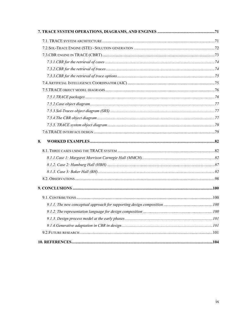
7. TRACE SYSTEM OPERATIONS, DIAGRAMS, AND ENGINES ........................................................71
7.1. TRACE SYSTEM ARCHITECTURE ..............................................................................................................71 7.2.SOL-TRACE ENGINE (STE) - SOLUTION GENERATION ...............................................................................72 7.3.CBR ENGINE IN TRACE (CBRT)..............................................................................................................73
7.3.1.CBR for the retrieval of cases ...........................................................................................................74 7.3.2.CBR for the retrieval of traces ..........................................................................................................74 7.3.3.CBR for the retrieval of trace options ...............................................................................................75
7.4.ARTIFICIAL INTELLIGENCE COORDINATOR (AIC) .....................................................................................75 7.5.TRACE OBJECT MODEL DIAGRAMS...........................................................................................................76
7.5.1.TRACE packages...............................................................................................................................76 7.5.2.Case object diagram..........................................................................................................................77 7.5.3.Sol-Traces object diagram (SRS) ......................................................................................................77 7.5.4.The CBR object diagram ...................................................................................................................77 7.5.5. TRACE system object diagram.........................................................................................................79
7.6.TRACE INTERFACE DESIGN ......................................................................................................................79
8. WORKED EXAMPLES..........................................................................................................................82
8.1. THREE CASES USING THE TRACE SYSTEM ...............................................................................................82 8.1.1.Case 1: Margaret Morrison Carnegie Hall (MMCH).......................................................................82 8.1.2. Case 2: Hamburg Hall (HBH) .........................................................................................................87 8.1.3. Case 3: Baker Hall (BH) ..................................................................................................................92
8.2. OBSERVATIONS.........................................................................................................................................98
9. CONCLUSIONS .........................................................................................................................................100
9.1. CONTRIBUTIONS .....................................................................................................................................100 9.1.1. The new conceptual approach for supporting design composition ................................................100 9.1.2. The representation language for design composition ....................................................................100 9.1.3. Design process model at the early phases......................................................................................101 9.1.4.Generative adaptation in CBR in design.........................................................................................101
9.2.FUTURE RESEARCH..................................................................................................................................101
10. REFERENCES..........................................................................................................................................104
x
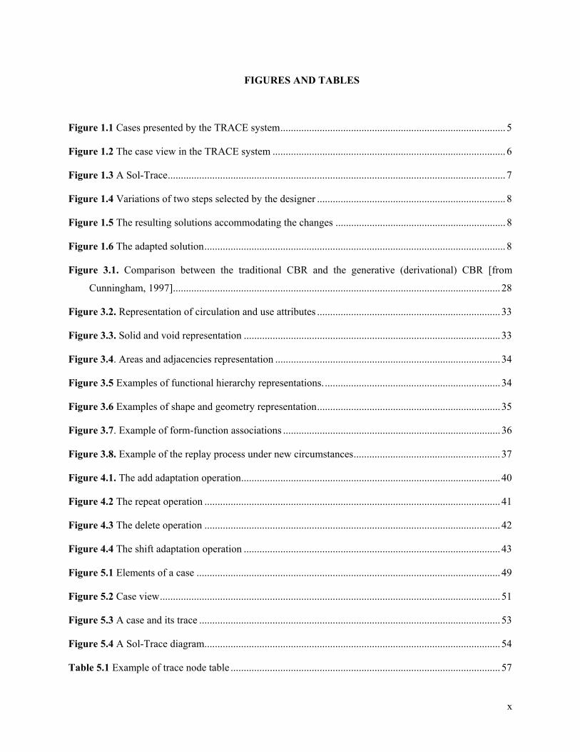
FIGURES AND TABLES
Figure 1.1 Cases presented by the TRACE system...................................................................................... 5
Figure 1.2 The case view in the TRACE system ......................................................................................... 6
Figure 1.3 A Sol-Trace................................................................................................................................. 7
Figure 1.4 Variations of two steps selected by the designer ........................................................................ 8
Figure 1.5 The resulting solutions accommodating the changes ................................................................. 8
Figure 1.6 The adapted solution................................................................................................................... 8
Figure 3.1. Comparison between the traditional CBR and the generative (derivational) CBR [from
Cunningham, 1997]............................................................................................................................. 28
Figure 3.2. Representation of circulation and use attributes ...................................................................... 33
Figure 3.3. Solid and void representation .................................................................................................. 33
Figure 3.4. Areas and adjacencies representation ...................................................................................... 34
Figure 3.5 Examples of functional hierarchy representations.................................................................... 34
Figure 3.6 Examples of shape and geometry representation...................................................................... 35
Figure 3.7. Example of form-function associations ................................................................................... 36
Figure 3.8. Example of the replay process under new circumstances........................................................ 37
Figure 4.1. The add adaptation operation................................................................................................... 40
Figure 4.2 The repeat operation ................................................................................................................. 41
Figure 4.3 The delete operation ................................................................................................................. 42
Figure 4.4 The shift adaptation operation .................................................................................................. 43
Figure 5.1 Elements of a case .................................................................................................................... 49
Figure 5.2 Case view.................................................................................................................................. 51
Figure 5.3 A case and its trace ................................................................................................................... 53
Figure 5.4 A Sol-Trace diagram................................................................................................................. 54
Table 5.1 Example of trace node table ....................................................................................................... 57

xi
Table 5.2 Trace root table of solutions. The numbers indicate the selected options at each node............. 58
Figure 5.5. Classification scheme in the TRACE system .......................................................................... 59
Figure 5.6. Formative Idea classification example .................................................................................... 61
Figure 6.1 Options at a trace node ............................................................................................................. 65
Figure 7.1 TRACE system architecture ..................................................................................................... 72
Figure 7.2 TRACE system main design packages ..................................................................................... 76
Figure 7.3 Case object diagram.................................................................................................................. 77
Figure 7.4 Sol-Trace (SRS) object diagram............................................................................................... 78
Figure 7.5 CBR object diagram ................................................................................................................. 78
Figure 7.6 TRACE system object diagram ................................................................................................ 79
Figure 7.7. Sol-Trace interaction windows ................................................................................................ 80
Figure 8.1 Perspective view of the MMCH building, before the addition at the long wing ...................... 83
Figure 8.2 First floor plan of MMCH bldg ................................................................................................ 83
Figure 8.3 The function diagram of the MMCH bldg................................................................................ 84
Figure 8.4 The form diagram of MMCH building..................................................................................... 84
Figure 8.5 The Sol-Trace for MMCH building.......................................................................................... 85
Figure 8.6 Composition steps variations.................................................................................................... 86
Figure 8.7 Generated alternative solutions................................................................................................. 87
Figure 8.8 The main façade of Hamburgh Hall ......................................................................................... 88
Figure 8.9 The first floor plan of Hamburgh Hall...................................................................................... 88
Figure 8.10 Function diagram of Hamburgh Hall...................................................................................... 89
Figure 8.11 Form diagram of Hamburgh Hall ........................................................................................... 89
Figure 8.12 Sol-Trace of Hamburgh Hall .................................................................................................. 90
Figure 8.13a Options in some of the HBH Trace nodes ............................................................................ 91
Figure 8.13b Options in some of the HBH Trace nodes............................................................................ 91
Figure 8.14 Generated solutions of Hamburgh Hall .................................................................................. 92
xii
Figure 8.15 Building façade Baker Hall .................................................................................................... 93
Figure 8.16 First floor plan of Baker Hall.................................................................................................. 93
Figure 8.17 Function diagram of Baker Hall ............................................................................................. 94
Figure 8.18 Form diagram of Baker Hall................................................................................................... 94
Figure 8.19 Sol-Trace of Baker Hall.......................................................................................................... 95
Figure 8.20 Options in some of the Baker Hall Trace nodes ..................................................................... 96
Figure 8.21 Generated solutions of Baker Hall.......................................................................................... 97
1
1. Introduction
1.1 The need for computational support in the building industry In architecture, early design is mainly done manually, not using computers, which results in a
particular set of problems in practice. Schedules are not always met; previous design mistakes are
repeated; and many times designs must be redone or undergo radical changes which result in cost and
time overruns. Assuring quality during the design phase is preferable to during the construction phase,
when corrections incur substantially larger costs. Frequently, design management is faced with trade-offs
between design quality and process time. There is a need to enhance this process through feedback and
through other methods and techniques. We need to reduce the gap between the design phases, particularly
between the early phases and the other phases of building process.
Computation has promising potential in enhancing creative thinking. This already has been realized
in many artistic fields such as graphic arts and musical composition [Novak, 2001; Bruton, 1977]. There
is a compelling need and opportunity to utilize computers in the conceptual composition of architectural
design. The research presented in this dissertation shows how design assistance can be achieved in the
early phases of design composition in order to facilitate the process, predict and avoid failures, keep track
of success, and develop innovative and creative solutions. Providing such assistance can also help in
ensuring the quality of the design even under tight schedules. Eventually, this will improve efficiency in
the building industry in general.
1.2 Research problem, motivation, and objectives Three challenges motivate this research. The first is the lack of computational support for the early
phases of the design process, particularly design composition. The second is the need for better
computational methods that address core problems of design composition. The third is the problem of
adapting prior cases in a manner that is feasible and useful for design composition in the case-based
reasoning approach (CBR).
1.2.1 Support early phases of the design process The importance of the early phases of the design process cannot be underestimated. The quality of
the design depends on the decisions made early in the process. In architectural design, continued
development of an infeasible concept will not improve the quality of the result. On the other hand, a
sound design concept at the outset would likely propagate through the later phases of design development
and encourage the emergence of better qualities in the result.
2
Integration with later design phases is needed. In most cases, when concepts are developed using
pencil and paper, it is hard to transfer the concept to electronic media without losing the flow of thought
or creative impulses. On the other hand, easy and fast simulations and analyses are available in
computational media, which are not available using pencil and paper. Integration can happen only if the
gap is closed between these design phases. Concepts and their development must be computationally
supported. In turn, computer support of design development phases has to be more receptive to the type of
computation needed for the early phases. In addition, using computation in the early process can enhance
the probability of reaching creative solutions through examples and precedents available in this media.
Computation and mathematical formalisms can also provide other venues for creative leaps.
1.2.2 The need for better suited computational methods Until recently, the majority of designers were more experienced in pencil and paper design than in
CAD, particularly at the early phases. It will be hard to change their practice unless CAD provides
accommodating methods and interfaces. There is a need for flexible CAD support that allows designers to
use computers as partners at this early phase. Design and usability of CAD software needs to be rethought
if designers are to use CAD in their early design sketching. The goal is not to make computers imitate
human designers; on the contrary, it is to allow computers to play a complementary role integrated with
the design process and to work with human designers. It is imperative to develop representations that can
be understood by both designers and computers in the early phases of the design. Such representations
will allow integration between designers and computers and enhance the use of computational methods.
Within the community of researchers and developers of computational systems and tools, knowledge
acquisition and representation are considered the bottleneck for many applications. AI methods and
techniques can help, but until recently, such methods were not applied to complex fields such as
conceptual design and targeted less complicated tasks. There is a need for extending AI methods and
techniques to support design tasks [Flemming, 1994]. This includes methods in knowledge representation,
reasoning, and collaboration with users.
1.2.3 Adaptation in CBR to fit the application field In CBR, adaptation is considered one of, if not the most, difficult problems, mainly because of the
need to represent both domain knowledge and problem solving knowledge, which violates the purpose of
using CBR in the first place to avoid such representation. On the other hand, the objectives of CBR, in
many applications, cannot be completely achieved without adapting the retrieved cases. This kind of
conflict has long troubled the CBR field. New models that build on CBR and accommodate effective and
feasible ways of adaptations are needed. Researchers have suggested many techniques to deal with the

3
adaptation problem, such as re-applying CBR methodology, the use of adaptation cases that hold similar
examples, adaptive retrieval, derivational adaptation and others. These techniques must be integrated into
CBR and tailored to the meaning of adaptation in the application domain [Leake, 1996].
As noted, the adaptation process is closely related to the specific domain that CBR is applied to. In
architecture it is difficult to precisely define or describe the adaptation process. Examples of CBR
systems in the architectural field [Chiu, 1997; Borner, 1998; Domesheck, Zimring & Kolodner, 1994,
Flemming, 1994a,, Maher, 1993,; Oxman, 1994; Raduma, 2000; Schaaf, 1995; Schmitt, 1994] have either
avoided the adaptation process or dealt with it in a very specific context. Therefore, there is a need to
suggest models for CBR that provide effective adaptations that match the architectural reasoning process.
1.2.4 Motivation Analogical reasoning and CBR match to a large degree the problem solving process in architecture,
particularly in the early phases. Cases, precedents, and analogies are widely used. Analogies to different
domains are drawn in many situations. This match is the motivation to explore how CBR technology can
provide computational support for the early conceptual design process.
Many design researchers have focused on the early design process, primarily looking at resolving
functional conflicts or building topology. In architectural design, a form must first be sketched before
embarking on a detailed solution or evaluating a solution. Form selection or generation is the core of the
process. The goal of this research is to provide computer assistance for finding design forms.
1.2.5 Research Objectives The goal of this research is to provide assistance in the early phases of the design process. The
research builds on the fact that designers use their education and expertise in the field when designing
new solutions. This thesis utilizes a new approach, in design knowledge acquisition and in developing
knowledge based systems for building design, in order to overcome difficulties associated with earlier
rule-based approaches. The research explores questions such as; can the machine mimic designer’s
behavior in recalling expertise? Can the representation of expert knowledge be a reliable source for
solutions superior to designer’s memory? Can this memory assist in solving design problems and
composing new design solutions? The research presented here uses a Case Based Reasoning (CBR)
methodology to address these questions.
This research uses CBR as a generative technique for design composition. Through the reuse of
cases, new forms will be generated. Instead of reusing the solution itself, the generative approach
abstracts and back-tracks the possible path of the solution. The solution path includes the decisions,
methods, alternatives, and special processes that were used to shape the design form. At the heart of this
4
approach is the concept of derivational analogy [Carbonell, 1985], which detects similarities in the
derivational path rather than the end solution. This derivational path, if reused in delivering new solutions,
could be described as a generative path. So, the approach is generative CBR, or G-CBR. This approach
requires representing of both the end solution and the derivational path.
The main objectives of this research are:
- To represent the design composition problem as accessible and usable constructs through a
language for abstracting the design intent or rationale
- To include the main functional characteristics in the representation, as architecture is not only
about shapes, but also about function
- To make intensive use of precedents in design, as this is how designers use their experience
- To resolve some difficulties in utilizing CBR technology in the design field, particularly in
adapting solutions, by using a model that relies on derivational analogy to capture design
intent and to replay and regenerate new designs.
1.3 Scenario for design composition: The TRACE system This dissertation describes the TRACE system, a Case Based Reasoning framework for form
composition in architecture. The chapters that follow describe the representations and manipulations of
the TRACE system in detail. To give the reader a sense of the scope and purpose of the TRACE system,
consider the following scenario, of the design of a new campus building.
Imagine the TRACE system is ready and installed on a designer’s computer. The designer is working
on a new assignment: to design a building for the college of fine arts in a leading university. The client
has received a large donation to be used for a new building that houses cutting-edge art studios. The
designer has read the brief, visited the site, and collected all the required information. The site is a
rectangular shape with a view on two sides. The theme of the development is blend of Beaux Arts and
post-modern architecture.
The designer is enthusiastic about the project and wants to come up with an innovative design. He
started with the sketches, only to realize that his mind is fixed on a design concept of a college building
which he designed two years ago. His sketches were only variations of that design: a classic heavy square
shaped building with variations in the ratio of internal divisions. So, the designer decided to use the help
provided by the new CAD system that he acquired recently, the TRACE system.

5
The designer asks the TRACE system to help in finding other possible compositional concepts for
the college building. The designer starts by entering the functional characteristics that he would like in the
new design such as areas, number of floors, divisions, etc. Then, the designer enters the desired form
characteristics of the building. The designer selects characteristics such as circular and rectangular shapes,
mainly he wants to avoid squares and pursue more innovative artistic forms.
TRACE retrieves three cases of buildings that are stored in the system (Figure 1.1). These cases
match the requested characteristics. The designer eagerly browses these designs and selects one of them
as a promising concept. Figure 1.2 shows the case view of the selected design. The designer does not
want to imitate the design there; he is just inspired by the concept in the design and wishes to find a
similar form that fits his new building.
Figure 1.1 Cases presented by the TRACE system
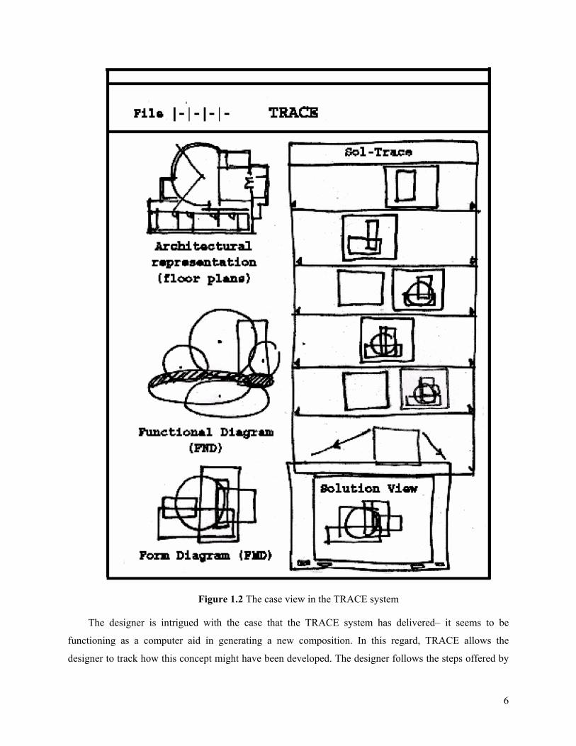
The case view, as in Figure 1.2 contains attributes of the building, architectural representations and
other functional descriptions similar to a bubble diagram. It also contains a simple diagram representing
the salient features of the form in an abstracted way. The designer looks carefully at how neatly this form
diagram abstracts the concept in the architectural plan. He can relate the design elements and their
transformations in both views. The designer becomes more excited about the composition concept and
expects a similar interesting form for his building to come out of it.
6
Figure 1.2 The case view in the TRACE system
The designer is intrigued with the case that the TRACE system has delivered– it seems to be
functioning as a computer aid in generating a new composition. In this regard, TRACE allows the
designer to track how this concept might have been developed. The designer follows the steps offered by
7
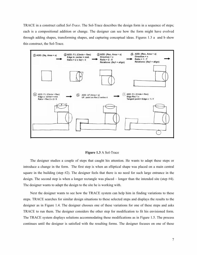
TRACE in a construct called Sol-Trace. The Sol-Trace describes the design form in a sequence of steps;
each is a compositional addition or change. The designer can see how the form might have evolved
through adding shapes, transforming shapes, and capturing conceptual ideas. Figures 1.3 a and b show
this construct, the Sol-Trace.
Figure 1.3 A Sol-Trace
The designer studies a couple of steps that caught his attention. He wants to adapt these steps or
introduce a change in the form. The first step is when an elliptical shape was placed on a main central
square in the building (step #2). The designer feels that there is no need for such large entrance in the
design. The second step is when a longer rectangle was placed – longer than the intended site (step #4).
The designer wants to adapt the design to the site he is working with.
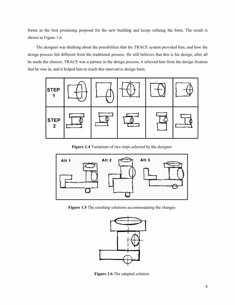
Next the designer wants to see how the TRACE system can help him in finding variations to these
steps. TRACE searches for similar design situations to these selected steps and displays the results to the
designer as in Figure 1.4. The designer chooses one of these variations for one of these steps and asks
TRACE to run them. The designer considers the other step for modification to fit his envisioned form.
The TRACE system displays solutions accommodating these modifications as in Figure 1.5. The process
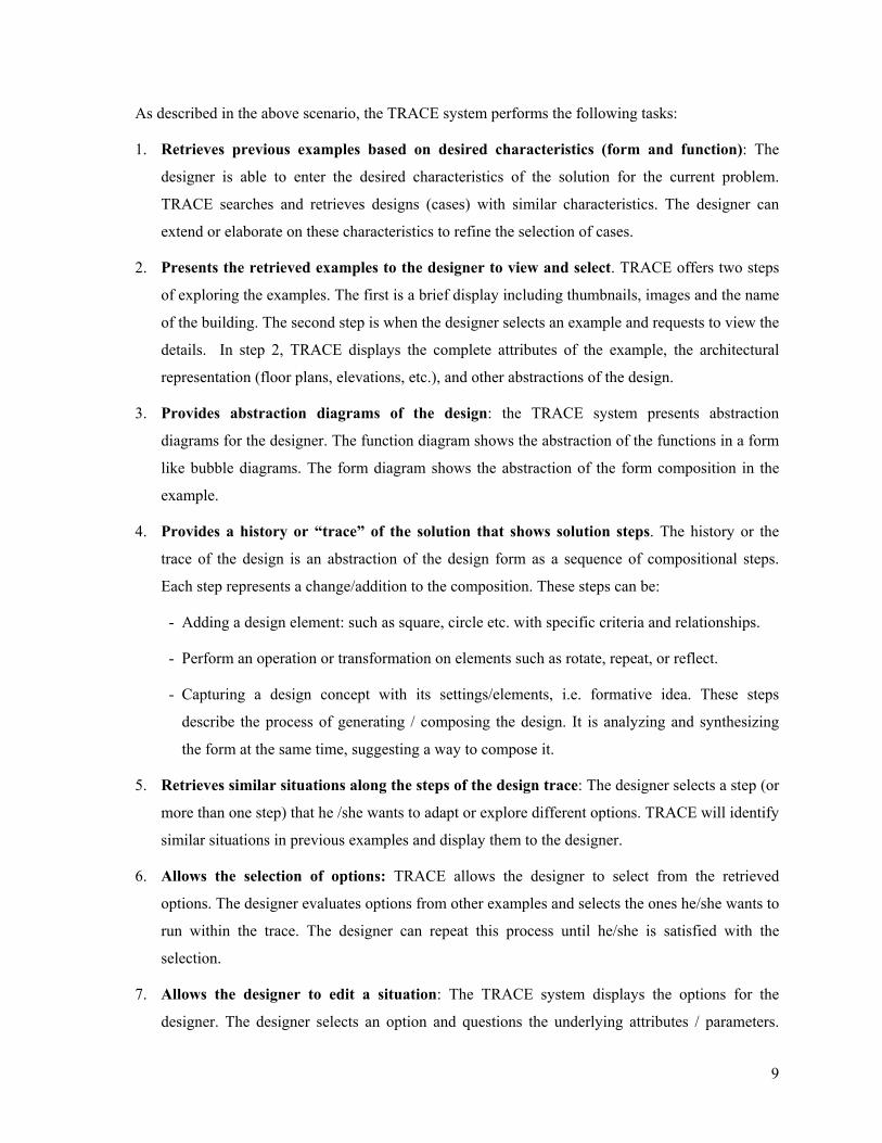
continues until the designer is satisfied with the resulting forms. The designer focuses on one of these
8
forms as the best promising proposal for the new building and keeps refining the form. The result is
shown in Figure 1.6.
The designer was thinking about the possibilities that the TRACE system provided him, and how the
design process felt different from the traditional process. He still believes that this is his design, after all
he made the choices. TRACE was a partner in the design process; it relieved him from the design fixation
that he was in, and it helped him to reach this innovative design form.
Figure 1.4 Variations of two steps selected by the designer
Figure 1.5 The resulting solutions accommodating the changes
Figure 1.6 The adapted solution
9
As described in the above scenario, the TRACE system performs the following tasks:
1. Retrieves previous examples based on desired characteristics (form and function): The
designer is able to enter the desired characteristics of the solution for the current problem.
TRACE searches and retrieves designs (cases) with similar characteristics. The designer can
extend or elaborate on these characteristics to refine the selection of cases.
2. Presents the retrieved examples to the designer to view and select. TRACE offers two steps
of exploring the examples. The first is a brief display including thumbnails, images and the name
of the building. The second step is when the designer selects an example and requests to view the
details. In step 2, TRACE displays the complete attributes of the example, the architectural
representation (floor plans, elevations, etc.), and other abstractions of the design.
3. Provides abstraction diagrams of the design: the TRACE system presents abstraction
diagrams for the designer. The function diagram shows the abstraction of the functions in a form
like bubble diagrams. The form diagram shows the abstraction of the form composition in the
example.
4. Provides a history or “trace” of the solution that shows solution steps. The history or the
trace of the design is an abstraction of the design form as a sequence of compositional steps.
Each step represents a change/addition to the composition. These steps can be:
- Adding a design element: such as square, circle etc. with specific criteria and relationships.
- Perform an operation or transformation on elements such as rotate, repeat, or reflect.
- Capturing a design concept with its settings/elements, i.e. formative idea. These steps
describe the process of generating / composing the design. It is analyzing and synthesizing
the form at the same time, suggesting a way to compose it.
5. Retrieves similar situations along the steps of the design trace: The designer selects a step (or
more than one step) that he /she wants to adapt or explore different options. TRACE will identify
similar situations in previous examples and display them to the designer.
6. Allows the selection of options: TRACE allows the designer to select from the retrieved
options. The designer evaluates options from other examples and selects the ones he/she wants to
run within the trace. The designer can repeat this process until he/she is satisfied with the
selection.
7. Allows the designer to edit a situation: The TRACE system displays the options for the
designer. The designer selects an option and questions the underlying attributes / parameters.

10
The designer can change some of these attributes/parameters and the TRACE accommodates
such changes.
8. Replays the selected modifications and generates and displays solutions: TRACE runs the
selected options within the trace abstraction and displays the resulting solution to the designer.
9. Generates more than one solution to accommodate further modifications: TRACE continues
to generate solutions using different options selected or modified by the designer. TRACE keeps
track of these solutions. The designer evaluates these solutions and decides which ones to use
and/or to keep in the trace for later use.
1.4 Overview of the dissertation This research proposes an abstraction for architectural design composition in the early phases of the
design process. The abstraction is a language, represented computationally, while presented visually to
the designers. Cases in this research are previous architectural designs, represented in 2D floor plans. A
new construct Sol-Traces is proposed to hold the compositional characteristics (path) of the design, for
both function and form. The research proposes a toolkit for creating and adapting these traces. New
designs are developed through the reuse, adaptation, and replay of Sol-Traces.
Cases are previous design forms abstracted and represented in a syntactical way using the Sol-Trace
representation. The Sol-Trace representation is suitable for design composition, exploration, adaptation,
and development at the early phases of the architectural design process. Traces are stored solutions and
are used to develop new solutions for the current problem. The process starts with matching the design
problem, which is given by a set of functional requirements and desired form characteristics, against cases
stored in the case base. Then, the retrieved cases are adapted and reused and new cases are added to the
case base. The research proposes the TRACE system as a generative CBR system using the concept of
Sol-Traces.
Chapter 2 of this dissertation covers the required background and literature review for this approach
of supporting design composition. An overview of the Sol-Traces approach is provided in Chapter 3. In
Chapter 4, the compositional steps of traces are presented. This followed by the representation of cases
and Sol-Traces in chapter 5. Chapter 6 is devoted to the generative adaptation of traces. In chapter 7, the
TRACE system operations, diagrams, and engines are discussed. This is followed by a three worked
examples in chapter 8. Finally, conclusions and future research are presented in chapter 9.
11
2. Background and literature review
The term CAD refers to a wide range of computational assistance to the design process. It ranges
from simple or marginal assistance to complete design automation. In architecture, this assistance started
with developing formal methods for describing the design process and products. The need to manage and
formalize the process was the focus in the design methods movement of the early sixties when pioneers
such as Christopher Jones started to describe the design process in the form of methods [Jones, 1963].
Design patterns, as suggested by Christopher Alexander, were among the efforts in the 1970’s to
formalize the design process in architecture [Alexander, 1977]. This movement did not achieve fruitful
results: many objected that the design could not be confined merely within methods, but it did bring
attention to the field of design research. Following the methods era, computers and computer aided design
were introduced to the profession in the late seventies. Expectations were high and pioneers dreamed of a
machine that could compose a design solution [Mitchell et al., 1977].
During the past two decades (1985-2005), the design process has been represented and described in
several ways to attempt to realize our dream. Design problems have been reduced to a set of small or
abstracted processes that can be represented, performed, and managed computationally. Yet the dream has
not been realized and the results are still far from satisfying. In the late eighties and early nineties, the
CAD research community explored the cognitive aspects of the design process through protocol analysis,
and other techniques [Cross et al., 1994].
Now we know more about the design process than two decades ago, only to realize that the design
process can most appropriately be computationally assisted rather than automated. Computers can
perform some tasks well and exceed human capabilities; these tasks include remembering and numeric
calculations. At the same time, only humans can perform well and, at least so far, exceed the capabilities
of computers on tasks such as complex reasoning and design. With this understanding, many systems
have been proposed to assist designers. These systems target specific components of the design process,
such as functional analysis, shape manipulations, and visualization. With advances in computational
hardware and software, CAD techniques are being re-examined and re-tested.
This chapter reviews design composition and computer support for analogical reasoning in
architectural design, and case based reasoning. The use of typology in design is also reviewed for the
application of CBR in solving design problems. The state of the art of CBR applications in design
composition is reviewed, including approaches, systems, and comments on opportunities for advancing
the field.
12
2.1 Design composition Design composition can be defined as assembling design components in a way that gives a specific
character to the solution. Design composition in architecture is often referred to as the ‘order’ in the
solution. This order is introduced during the design process and can be seen in the floor plan of the
building. The design order goes beyond the visual order, as it is connected to many other aspects such as
component types and forms, functional relations between components, and construction techniques.
In many cases introducing order during the design process helps generate a solution that better
fulfills the requirements. The order suggests a way to group these requirements or even to improve the
way these requirements interact. As the order itself represents a design composition that is more readily
accommodated in a building than the requirements, introducing this order may actually augment the
accommodation or better fit of these requirements in the solution. At least it may offer the designer a
clearer understanding of these requirements, which leads to finding better suited solutions.
Design composition, also called form composition, is the process of imparting this order to the
building form. Architects often judge buildings by these forms, and reaching what is considered to be
creative and or innovative is always a rewarding endeavor. Design theorists have been interested in
describing order in design and how to compose a design form that satisfies a wide range of needs.
Principles of form design are well presented in literature by many architectural researchers and
practitioners [Krier, 1988; Wong, 1993; Wong, 1988; Baker, 1993; Flemming, 1990; Clark and Pause,
1996; Oxman et al., 1987]. These design composition principles are represented in both 2D and 3D forms.
In most cases, form principles are attached to other functional values, and form composition is also
affected by construction methods and materials.
Design composition can be described at many levels of abstraction. Design principles provide a high
level of abstraction; however, the components of a design composition can also be described at a lower
level. According to Wong, basic design elements and transformations are the main ingredients of form
representation and provide a language for describing higher level form principles. These are the building
blocks for developing form. Wong proposed four categories of basic design elements [Wong, 1993;
Wong, 1988]:
• Conceptual elements: point, line, plane, volume
• Visual elements: shape, size, color, and texture
• Relational elements: direction, position, space, gravity
• Practical elements: representation, meaning, function
13
These categories constitute different types of compositional elements in form design representation.
Wong demonstrated that, through transformations performed on these elements, a variety of design forms
can be generated. Others present similar basic transformations [Ching, 1979]. Gargus lists: rotation,
reflection, shifting, shearing, displacement, variation, reversal, scaling, inversion, recursion, nesting, and
hierarchy as basic transformations of forms [Gargus, 1994]. Higher design principles, such as symmetry,
balance, emphasis, rhythm, proportions, and the sense of space or motion, derive from these basic design
elements and transformations. Repetition of shapes along a curved line can imply motion and identical
compositions reflected about an axis can provide symmetry; most design composition principles can be
represented in this way. The representation of form that reflects such principles are in many cases referred
to as ‘Parti’ [Gargus, 1994; Clark and Pause, 1996; Krier, 1988]. Krier provides an extended analysis for
form composition in architecture. His analysis is divided into four main parts: representation, operations,
elements, proportions. Operations such as kinking or bending, shifting, and overlapping are among the
identified form transformations. Other compositional principles are based on the use of analogies and
metaphors and through the utilization of types in form design. Design principles remain relatively
constant over time, but the types of generated compositions change from one generation to another.
These same principles can account for different architectural styles through decades. However, the
emphasis on specific principles can shift, with technology playing a crucial role in this shift. New styles
and building types are constantly created and the underlying design principles are refined and augmented.
Recently, the use of computers and graphic media has changed many of these traditional building types
and how they are utilized. Using computers architects are creating new building styles. The limitations of
the computational media in have created a unique kind of abstraction. Images of these views became
icons in designers’ minds are now pursued as styles in their own right. No doubt, such abstraction will
influence the underlying design principles and open a window for new approaches from these principles.
On the other hand, functions are no longer rigidly confined within physical spaces; the mobility of
work space and the flexibility of spaces in accommodating several different functions are among recent
paradigms in design [Mitchell, 2002]. This affects how form principles can be applied in the design
process and what they can achieve. In other words, a relaxation of the functional design requirements is
anticipated, which leaves more opportunities for form composition principles to take advantage of.
In architecture, computer support for design composition has used many different approaches,
including shape grammar formalisms [Flemming, 1987], graphics algorithms [Mitchell, 1994; Kolarevic,
1997], evolutionary computations [Jakimowicz et al., 1997], and fractals [Frazer, 1995; Bruton, 1997].
However, architectural design practice still needs further research in order to fully utilize computation in
practical ways in the design process, particularly in design composition.
14
This thesis proposes a technique for computer support for design composition by reusing previous
design form principles encoded in cases. This approach develops a language for representing these
principles and utilizing them in new situations. It includes a method for representing design episodes
encapsulated within these principles. These principles are decomposed into simple rules, alternatives, and
decisions along behind them. The approach uses a case based reasoning methodology to deliver assistance
in design composition.
Although the research proposed composition transformations resemble, to some extent, rules used in
shape grammars formalism there are crucial differences between the proposed approach and shape
grammars. First, shape grammars do not explicitly provide a language for representing design principles.
In shape grammars usually rules can be applied freely and generate unpredictable compositions. There is
not much relevance to the particular design that these grammars are built from. Second, although based on
the same corpus of geometry, the methods in this approach are different. Shape grammars do not use the
sequential character of design composition presented in this approach. Recently shape grammars
approaches have used parallel grammars or others techniques to achieve objectives or goals in the process
[Knight, 2001], which is also different from the representation of design composition in this research.
Thirdly, this approach restricts the process to form composition using cases, and the proposed
composition strategies are not automated as in shape grammars. The transformations are provided as
operational tools to the designer, who chooses when and where to apply them.
Another important difference is that grammars usually are developed from a set of numerous designs
and require great effort to build and test. The research approach simplifies this process through relying on
cases without generalizing these rules. This enables the designer to easily build and extract his own
specific composition strategy, developed from specific cases, without going through the tremendous effort
of generalizing these rules for the use of other designers only to realize that they favor development of
their own rules; as Knight points out:
…in architecture and the arts, fields with a heavy emphasis on originality and novelty, it seems unlikely that a designer would implement any grammar but his or her own
[Knight, 2001, pp. 4-5]
2.2 Analogical reasoning in architectural design Architectural design is a complex task that requires high level cognitive resources. Designers often
use heuristics and strategies to accomplish this process.. These strategies differ from one design task to
another. They are used to overcome difficulties in the design process, such as reaching creative ideas,
resisting design fixation, and avoiding earlier design failures. Among these strategies is the use of
analogy. Designers rarely start from scratch when faced with new design problems. They usually refer to
15
and build analogies based on their previous experience. In practice, they often face problems similar or
analogous to ones they have encountered and solved in the past. The analogy can be to solutions, or to the
way they derived those solutions, or at least some aspects of those solutions. Past solutions are held in
long term memory and accumulated through years of practice. The process of using analogies in problem
solving is called analogical reasoning. Analogical reasoning appears to play a key role in creative design
[Falkenhainer, Forbus, and Gentner, 1989; Bhatta et al., 1994; Schmitt, 1995; Casakin & Goldschmidt,
1999; Qian and Gero, 1992; Chiu et al., 1997].
In architectural design, designers refer to past experience in many ways as heuristics and techniques
to solve the design problems, or as design solutions that provide exemplars of similar classes of design
problems. How designers refer to past experience is not clearly articulated in design research and, in
many cases, is considered part of the design process itself. Much research has attempted to investigate
details of this analogical use of memory and described these exemplars as design precedents, or case
studies [Bhatta et al., 1994; Goldschmidt, 1995].
Analogy takes place in the designer’s mind. Models of human memory in the field of cognitive
science describe the mechanism of how this information is stored and retrieved. Among the well-known
models is Tulvering’s model for human memory [explained in Konar, 2000]. This model divides memory
into three parts: sensory memory for receiving information, semantic memory for conceptual inferences,
and procedural memory to hold actions and procedures resulting from the conditions from semantic and
sensory memory. In architecture, sensory memory records information pertaining to how architecture is
experienced such as seeing, feeling. Semantic memory holds previous ideas, aspects, characteristics of
design solutions and their connections, whereas procedural memory holds actions related to the derivation
of solutions and actions specifically related to the techniques used in the design process.
Research in cognitive science has found analogy to play a large role in human reasoning, especially
for challenging tasks such as planning or design. Analogy also permeates the different techniques for
using past experience, such as avoiding previous similar failures, finding new concepts analogous to
particular objects, or reusing applicable design precedents. Analogies can refer to natural or human made
objects. Examples are well known in design precedents such as Le Corbusier’s habitat that resembles a
ship, Utzon’s Sydney Opera House that is analogous to a sail or a ship, and others [Goldschmidt, 1995;
Schmitt, 1995]. The use of analogy can be conscious or unconscious; designers may unintentionally draw
these analogies in their minds, or they may intentionally employ an analogy to appeal to shared metaphor.
In architectural design, ideas and concepts come from analogies from other domains. This
phenomenon can be investigated as a possible type of design solution sources. Research in analogy and
metaphor has focused on the nature of the mapping process between source and target. Gentner’s
16
“Structural mapping” theory [Gentner 1983] emphasizes the use of deep characteristics rather than face
attributes in the mapping process. The Structural Mapping Engine (SME) [Falkenhainer, Forbus &
Gentner 1989] and networks of abstractions and analogies was developed [Hampton 1998; Bonnardel et
al., 1998]. It is a computational implementation of Gentner’s structure mapping theory of analogy.
2.3 Case based reasoning in architectural design Case Based Reasoning is both: a memory organization and a problem solving methodology. CBR
uses a knowledge representation technique called ‘cases’. Through recalling these cases and reasoning
with them, solutions to similar situations can be found. CBR systems can be viewed as a form of
knowledge based or expert system. Unlike some other CBR systems, CBR does not consist of generalized
rules but a memory of stored cases recording specific episodes, situations, or lessons. CBR techniques
have been used successfully in many applications in different domains.
The proposed research adapts CBR to suit the reasoning process in design: the solution process is
shared between computers and designers; knowledge is partially represented; and designers provide the
required ‘glue’ to assemble this knowledge in a new design solution. This research will examine CBR as a
problem solving technique and apply it to one of the most demanding tasks; design composition in
architecture.
In design practice, previous experience or previous design solutions are represented, stored,
retrieved, and reused in many ways. This experience is sometimes referred to as design precedents or
design memory [Oxman, 1994a]. In fact, the design process can be viewed as a stream of episodes of
previous situations reused and adjusted to produce a coherent new design solution. As quoted from
Bermudez by Downing, design memory plays a large role in many aspects of the design process:
Memory is knowledge. Memory can be used to help simulate new situations by means of exemplars. Memory liberates and traps: it librates by giving framework for action, from which such action then may depart; it traps, as the framework may be so strong that it proves impossible to break free of it. Memory is, to an extent, the universe of discourse. It establishes the reference point from which criteria and exemplars are utilized to accept/reject/develop ideas. Memory structures and shapes our perception of reality. Memory is generated and generates (supports and supported by) a set of social habits used in everyday life to ensure social interaction (predictability). A good design use of memory should avoid its direct, literal utilization; otherwise, the mind avoids inquiry and falls into mechanical, uncritical behavior and stereotypes. The problematization of memory is essential. One does it by de-framing the context of thought, so that memory has to be used in different, indirect manner. Design, as a process of action/inquiry, develops a memory.
Julio Bermudez Quoted by Frances Downing in Remembrance and the Design of Place [Downing, 2000]
This research builds on the notion of design memory or expertise and develops a methodology for
utilizing this memory in finding and composing design solutions. The CBR approach is based on
remembering and encoding previous design expertise. Using CBR as the main methodology in a
17
computer assistance system provides a test of this concept of utilizing memory in design. From a
computational point of view, CBR has the potential of providing innovative and creative design
compositions.
Computer implementations of analogical reasoning have been proposed to model the human thinking
process. Analogical reasoning engines have been implemented in many research projects in the computer
science community with good results in specific settings. More details about analogical reasoning can be
found in the literature [Gentner, 1983; Kedar-Cabelli, 1988; Turner, 1988]. Traditional AI methods fall
short in problem solving in unstructured domains such as design, planning, and diagnosis. AI approaches
rely in general on knowledge of a problem domain and tend to solve problems from first principles. In
unstructured domains such as design this approach is not always feasible and the results tend to be trivial
or unrealistic. A more feasible computational approach avoids representing deep domain knowledge and
uses analogy knowledge instead, reasoning with cases that represent specific situations and related
knowledge. Case based reasoning is one application of this approach, which makes CBR a more feasible
machine reasoning technique in the design domain. CBR is a special case of analogical reasoning.
The intuition of case based reasoning is that similar situations are repeated and what was done in one
situation is likely to be applicable in a similar situation [Kolodner, 1993]. Historically, CBR was founded
on the theory of dynamic memory [Schank, 1982] and recently, CBR has been applied in many different
fields, including classification, design, planning, and diagnosis [Juris, 1993; Watson & Perera, 1997; Pu,
1993; Smyth &Keane, 1996]. As CBR is the main methodology to be used in this research, it will be
discussed in more detail in this section.
When people solve problems, they frequently remember previous problems they have faced. This
remembering happens in many situations and reflects our constant search for old information to help in
processing new information. We constantly accumulate new cases and compare them to the cases we
know in an effort to understand the next case that appears. Often, we make rules or theories from cases
and remember the rules instead of cases, but we still need to have access to a wealth of cases from which
to understand and generalize.
Case based reasoning (CBR) emphasizes the role of situated experiences. CBR makes analogies
between the current problem and previously-encountered situations. As in analogical reasoning, case
based reasoning involves search, match and transfer. It starts with describing a problem, then searching
for similar past problems. Once a matching problem is found, its solution can be transferred and reused in
the current problem. In CBR terminology, these processes are referred to as: index, retrieve, adapt, reuse,
revise, and retain, known as the CBR cycle [Aamodt and Plaza, 1994].
18
The four steps of the CBR cycle can be described in greater detail:
1. Indexing: Indexing is the selection of features that tend to predict solutions and outcomes of
cases. Indexes can be used to construct a case memory and to access cases efficiently.
Vocabulary, descriptions, and classifications are used to index cases in the case base.
2. Retrieval: CBR Retrieval involves matching a query to find the most useful case to the problem
at hand. Matching maybe inexact. A similarity measure must be developed to allow retrieving
the most beneficial cases. The retrieved case provides a solution to the new problem.
3. Reuse – Revise (adaptation): Reuse and revision involve adapting the retrieved case to fit the
problem at hand. In general, this process is referred to as adaptation.
4. Retain: When a new case is developed after modifying or adapting an old case, the modified
case has to be retained and stored in the case base for later use. This new case should be indexed
in the same way as the original cases.
Early applications of CBR were developed around the concept of providing memory as a repertoire
of cases or situations and organizing them for effective retrieval. Memory models are the subject of much
research in cognitive science. Early models such as memory organization packets (MOPS) were
developed by Schank [Schank, 1982]. Recent knowledge representations and encoding techniques for
memory models include frames or classes.
Initially, CBR was thought of merely as a memory model to help in remembering previous
situations. CBR now is a methodology for problem solving that can be used in wide range of applications
such as design, planning, configuration, and diagnosis. CBR is extremely useful as a knowledge
acquisition and representation techniques in less-structured domains such as design. Knowledge is
represented through cases without trying to represent deeper domain knowledge. CBR provides several
means for representing knowledge that can help in modeling the application domain – referred to as
knowledge containers. These knowledge containers can be found in cases and their contents, the
vocabulary used to describe and index cases, the similarity measure used when matching cases, and in the
solution adaptations or transformations [Lenz et al., 1998]. The use of CBR in design is generally referred
to as case based design (CBD). However, CBR can be applied in design at different levels. It can provide
only explanations, indexing and retrieving of design solutions, or it can be used as a complete design
problem solver. The CBR cycle can be completely or partially developed within an application. For
example, many applications stop at the retrieval of solutions, leaving the user to adapt the case to the
problem at hand. Other applications place less emphasis on retrieval and provide complete adaptation
methods. Refer to [Watson and Perera, 1997] for more detailed listing of CBR applications and systems.
19
2.3.1 Cases and case representation The purpose of cases is to represent experiential knowledge, regardless whether this knowledge is
false or true, useful or not etc. A case records an episode where a problem situation was completely or
partially solved. A case thus represents an episodic coupling of problems and solutions. The process can
be described as a function between domain P (problems) and domain S (solutions) where cases are the
pairs (problem, solution). The effect or feedback of this solution can also be detected and added to the
case. Cases are represented as simple vectors of these pairs. In many situations, evaluation of the solution
is provided with the case. A domain of evaluations (E) can be added and the case will be the triplet (P, S,
E) or (P → S, E). In the case base, where these cases are stored, indexed, and retrieved, data structures
hold and access these cases. Data structures can be as simple as a flat list of pair-represented cases or
more elaborately structured, such as a decision tree.
2.3.2 Similarity measures, case indexing, and case retrieval Retrieval is a basic operation in reasoning with cases. A query to a CBR system presents a problem
and retrieves a solution by matching problem with cases in the case base. The match, which may be
inexact, is based on assessing the similarity between the new problem and existing cases. As described in
[Borner, 1998], there are two different approaches to similarity assessment in CBR; the similarity
approach and the representational approach [Kolodner, 1993].
In the similarity approach, cases are stored in an unstructured way and retrieved based on their
similarity to the problem at hand. The usefulness of a case is estimated based on the presence or absence
of certain features. Similarity is assessed through numeric computation and results in a single weighted
sum, which is intended to reflect all aspects of the similarity. Strategies are proposed to reduce the
complexity of structural comparisons such as multi-stage filtering or mapping.
In the representational approach, the cases are pre-structured and retrieved by traversing the index
structure, e.g. memory organization packets (MOPS) [Schank, 1982]. Similarity is assessed based on the
location of the case in the indexing structure; neighbors are assumed to be similar. Other indices in the
memory help in retrieving useful cases.
Indexing of cases is a memory set up which allows retrieval of cases such that the right cases are
retrieved at the right times and in an efficient way. In CBR there are two main models of case
organization, namely feature or classification based organization. Feature based organization: in which
features are used to organize cases and to provide access to cases in a rather simple expandable data
structure. Classification based organization: the class of the current problem is identified, and then used to
access a number of cases related to this class rather than searching in all directions.
20
2.3.3 The adaptation process In adaptation, retrieved cases are revised and adjusted to fit the new situation. Adaptation is
considered one of the most difficult tasks in developing CBR systems, because it requires modeling
domain knowledge. This is against the premise that CBR minimizes the need for deep domain knowledge
modeling. Many CBR applications either skip this process or develop strategies to reduce its impact on
the system [Leake, 1996]. There are three general kinds of adaptation [Cunningham and Slattery, 1994;
Kolodner, 1993]:
• Parametric adaptation: such as substitution, instantiation, parametric adjustments. In this
adaptation type, attributes or parameters of the solution are adjusted to make the overall
solution fit the new problem. This type of adaptation usually does not include deep changes
to the retrieved solution.
• Structural adaptation: This is more elaborate than adjusting parameters. It involves the
repair of certain aspects in the solution to fit the new problem, for example applying certain
rules or other manipulation to the solution. It is similar to the transformational analogy
approach where analogy to the stored problem requires transforming the stored solution to
fit the new problem [Carbonell, 1985]. Many techniques are used in this type of adaptation
such as the use of rules or grammars or model-guided repair.
• Generative adaptation: This type of adaptation differs greatly from the previous ones. It
involves reformulating solution to fit the new problem. The adaptation is applied to the
problem solving episode or techniques rather than to the solution. The process of
regenerating the solution is referred to as “the replay” process. Carbonell described this
approach as derivational analogy and called the replay “derivational replay” [Carbonell,
1985]. As this approach is adopted in this thesis, it will be explained in more detail in the
following chapters.
2.4 Architectural typology and CBR Type in architecture has a broad meaning and carries significant knowledge for the design product,
the process, and the relations among elements. Typology in general is the categorization of elements to
reflect certain characteristics and relations. Enumeration of elements is part of typology. In architecture,
there is a broad set of characteristics and relations that are used in the formation of types such as spatial,
functional, or organizational and many others. The term “Typology” has many different meanings. It may
serve as a definition for classifications, design knowledge containers, or models of designs or design
solutions. Architects usually think in terms functional typologies, formal typologies, and others. Thinking
21
of typologies in the design process allows the transfer of known solutions’ characteristics to new related
architectural problems. In this way, typology can serve as a basis for analogical reasoning [Leupen et al.,
1997]. For more explanation of types and typology in architecture, refer to [Aygen, 1999].
Typologies can be classified as: building types (models or functional typologies), organizational
typologies, and elemental typologies. A building typology represents the specific characteristics of a
particular class of building use such as schools, hospitals, or churches. It includes aspects related to that
particular type of building such as needs and uses. An organizational typology (spatial organization)
provides a general framework for solving problems related to the spatial distribution or the order of
functional elements. It involves topologies, spatial arrangements of functional elements, and rules or
patterns for formal composition. Layouts with courtyards, U shapes, or L shapes are examples of such
organizational typologies. Elemental typologies refer to prototypes for solving general classes of design
problems. They are generally related to the design of elements of buildings, for example, the entry to a
building, the type of vertical movement, or the level of privacy required. Also, one building or part of a
building may serve as exemplar of all the three categories of typology at the same time [Rowe, 1987].
Typologies play a crucial role in architectural design [Leupen et al., 1997; Gargus, 1994; Norberg-
Schulz, 2000; Gero, 1990]. Many designers use typology as a strategy to restructure their thoughts and
explore different design solutions. The concept of typology can be used through different levels of details
and abstractions. For example, a school building is a type of educational building; a classroom is a type of
space; a six-foot, double-hung door is a type of opening.
Typologies are often used in design computation. Building models are used in model-based
reasoning. Elemental typologies provide types of design problems that can be expressed as stories or
situations. Organizational typologies are central to layout problem representations (the space allocation
problem). However, typologies can also be used to support design composition as knowledge containers,
as alternatives, and as sources of composition to guide the design process.
In CBR, cases can be generalized patterns or configurations, which are similar to the patterns found
in organizational typologies [van Leusen, 1995]. Classification of cases is crucial to CBR because it is
part of the problem solving process. Organizational typologies are ideally suited for CBR for design
composition. Cases can be classified according to their geometric configurations. Some CBR systems
have used narratives about building elements and situations of design problems such as “design stories” in
the Archie II system [Domeshek & Kolodner, 1992]. Such systems utilize elemental typologies.
Typologies implicitly contain both iconic and canonic qualities of analogies that group instances of
the same categories together. Since CBR is based on analogy, this presents a link between CBR
22
methodology and the use typologies in design. In other words, typologies as classifications can serve as
logical containers of cases in a CBR application. This might imply that analogy is limited to previous
solutions that have been tried and found useful, and not useful in a new untested situation. However,
during the design process, in many cases, analogies can be drawn to experimental or hypothetical
situations. So, both historical examples and situations from current practice are good candidates for the
CBR methodology.
There is no doubt that typology is a valuable strategy in the design process, however, the
effectiveness of any heuristic in design depends on its appropriateness to the problem at hand. Hence,
both timing and contents of the typology are crucial to the process. In CBR, this can be translated into
identifying an effective and efficient retrieval mechanism based on carefully selected vocabulary and
classifications. Therefore, the proper choice of typologies as classifications for a CBR system should not
be underestimated.
2.5 CBR and building design CBR has been used to solve a variety of problems, from interpreting or explaining a solution to
automated solution generation. It is crucial to determine the specific problem and the nature of the
expected solutions for developing a successful CBR system. Building design has special characteristics
that differ from other design domains. Within building design, there is a wide range of activities with
many different design problems and solutions. In the early phases, the process focuses on developing a
preliminary list of functional requirements and a conceptualization of the building form. Throughout the
process, many smaller design problems must be solved, pertaining to site, form, environment, materials,
and structure. Given this diversity, computer assistance in architectural design should be specific to the
kind of problems being addressed and the expected solutions.
CBR has been used in many architectural systems. REALTOR is a simple system for the evaluation
of real-estate properties, based on prior experience in appraisal and sales [Cunningham and Slattery,
1994].
Archie II and DOORS are computer assistants for conceptual design. They provide indexing and
retrieval capabilities of many architectural resources. Archie II allows retrieval of recorded design stories
describing design mistakes and possible corrections [Domeshek & Kolodner, 1992; Domeshek et al.,
1994]. An extension for Archie II was developed to allow access cases using diagrams, which made
suitable for designers who are more adapted to the graphical notations [Gross and Do, 1994]. DOORS
allows for recording of browsing sessions for later use [Sklar, 1995].
23
HouseCAD is an early design assistance system for housing. HouseCAD assists design brief
development and conceptual design. In HouseCAD, a set of cases can be retrieved that fulfill the aspects
of the desired brief. HouseCAD uses a conceptual representation of the floor plan (bubble diagram) to
index and retrieve cases. It uses relative room positioning, coordinates, and orientation to represent basic
spaces within the house. HouseCAD relies on the dynamic cycle of selection and adaptation of the house
floor plan diagrams. HouseCAD is helpful in the early phases of the conceptual design, primarily for
functional layout design [Raduma, 1999; Raduma, 2000].
Oxman proposed several systems for precedent based design and memory management such as
MEMORIBILLA and PRECEDENT [Oxman, 1994b]. These systems use the approach of contents and
story-based representation by decomposing designs into tractable pieces of information. These systems
provide a CBR methodology for representing concepts and stories as cases, but do not provide
representations of the design composition.
CADRE is a design assistant for conceptual design. It goes beyond indexing and retrieval in allowing
elaborate adaptations for the retrieved cases. The cases are represented as 3D models with views of
structural, architectural and mechanical characteristics. Topological adaptation and case combinations are
supported as adaptation strategies with less emphasis on indexing and retrieval [Schmitt, 1995; Schmitt,
1994].
Kuhn and Herzog apply design patterns and a language game abstraction (LGA) to the design
process [Kuhn & Herzog, 1994]. Cases provide links between the configuration phrases and instances
that satisfy them. For example, a link between ‘concentric space’ and ‘dome’ can serve in the retrieval of
several useful cases. The approach relies on textual abstractions of cases and uses a language game
metaphor in representing and retrieving design cases. The LGA approach can provide a rich environment
for exploring design solutions including form compositions, but it focuses on retrieval of cases. Designers
must decompose the case, as in the traditional design process, in order to make use of the embedded
design concepts. What is relevant to design composition is the focus of LGA on configuration aspects and
the isolation of them from other contexts. This can provide rich selections and descriptions of design
composition components, concepts, and methods.
SEED is a CAD system for a wide range of design problems including requirements development,
layout design, and 3D enclosure modeling. SEED provides a clear representation of design problems and
solutions and utilizes CBR technology to manage the resulting solutions for later use and adaptation.
Adaptation in SEED is limited to the same editing capabilities that are used in the generation of solutions
[Flemming, 1994a; Flemming et al., 1997]. Application of SEED CBR approach in housing design was
24
developed to demonstrate capabilities of CBR in provide a repository of housing types and an interactive
retrieval using characteristics of house types [Lee, 2002].
FABEL is a design assistance system for technical installations. It utilizes previous installations to
create ones in the new buildings. FABEL uses a modular case representation that allows adaptation of
prior solutions, called Armilla 5 [Schaaf and Voss, 1995]. CADSYN is a structural design assistance
system that helps in designing structural system for high-rise buildings based on previous designs [Maher,
1993]. Rivard investigated the reuse and adaptation of building technologies, within cases, in conceptual
structural design [Rivard & Fenves, 2000]. Design composition is addressed in the SEED configuration
module, in which a well-composed outline is converted to a 3D mass. SEED uses first principles in the
generation of the layout design and relies on CBR technology to keep track of the generated solutions.
External solutions also can be entered using the SEED representation, but this is not the intended way to
use the system. SEED provides a module for configurations of the design but it has no representation for
the design composition itself, such as symmetry, gradation, rotation aspects etc.
2.6 Summary and implications for this research New approaches are needed before CBR can be utilized as a process model for design composition.
Explicit representations (called knowledge containers in CBR) of the vocabulary and process of design
composition are required. In addition, many aspects of design composition for CBR must be formalized,
i.e. vocabulary for indexing, operations, transformations, and adaptations.
Although CBR is a mature technology in other fields, in architectural design composition it is still in
an early stage of development. Many aspects of design composition are suitable for case representation
and problem solving. The capabilities of CBR can effectively aid in finding innovative solutions or
design compositions.
From the review of CBR approaches in design composition, these general observations can be made:
• Design composition is an imprecise problem; many aspects of early design are included in
composition, such as brief development, layout, and others.
• Aspects of design composition in cases are not made explicit beyond linking architectural
descriptions and classifications.
• In many cases, CBR is used within a larger system, not as the main reasoning engine.
• In design composition, many problems can be identified as suitable for CBR, but difficulties
arise in finding a representation for these problems and their solutions.
25
In this research, we consider precedents and their use from a computational perspective. We start by
defining what these precedents are and how they are used in the design process. We then investigate how
to represent these precedents and how to use them in this representation. We use the term ‘design
precedent’ in its architectural sense, that is, as a prior design that has some interesting architectural
characteristics for designers to refer to. These characteristics could be new building concepts,
organizations, physical characteristics or other intangible characteristics. We are concerned with building
a repertoire of these precedents in an efficient way to allow finding them and making use of them. To
accomplish this, we must address several requirements: First, we must identify the precedent
characteristics and make sure that the collection covers a variety of designs so that it is beneficial for
architectural designers. These precedents are documented in several types of formats such as images and
CAD drawings. We need to accommodate these formats, and to preserve those characteristics that depend
on the format. We need to understand why these precedents are interesting to designers. We need to
elucidate and isolate these interesting characteristics to make them available to designers, so that they can
retrieve them precisely and efficiently. This must be done carefully to keep them in context and not lose
their inherited characteristics. We need to know how designers will use cases, in order to develop
representations that enhance their use. Finally, we need to make sure that the representation is not so
complex that using precedents will demand too much time and effort. The following are aspects from the
design precedent that can be used in the design process:
• Function • Elements, spaces, circulation • Organization of functions & hierarchy • Form • Geometry and shapes • Organization • Ornaments, elements • Massing • Texture, materials • Technological aspects • Construction methods, materials • Environmental aspects
So far, in this chapter we have reviewed design composition as the main targeted problem in this
research. The use of analogical reasoning strategy in design composition was then reviewed. Analogical
reasoning is among the central issues in this research. Case based reasoning, which is part of analogical
reasoning, is then discussed. An overview of case based reasoning in architecture was provided. This
included the relations between CBR and typology in architectural design. The chapter ends with a
summary and implications for the research.
26
3. Overview of the Sol-Trace Approach
This thesis uses CBR and derivational analogy as a computational problem solving methodology for
architectural design, in particular for design composition. The theoretical frame of this methodology is a
proposed design composition process model and representational language that are shared and
understandable by both computers and designers. This process model and the representation language
allow the application of CBR to the complex processes of design. The traditional design process lacks
such powerful computation at the early phases; this research will enable design to benefit from such
resources. This thesis investigates the proposition that “if such a shared representation is provided the
design process will benefit.” By shared representation we mean a computationally represented language
for design composition. This argument stands on two main premises: first, the shared representational
process and language will not compromise the essence of architectural design composition, will not
trivialize the design problem, and will assist in solving the core design composition problems. Second,
utilizing this technology will benefit design. This can be answered through the argument that the
technology is or must be well-rooted in the design process, and that computation brings benefits by
providing a wider range of faster, accurate, unpredictable and interesting design solutions.
The following discussions will cover the main hypothesis and these two premises in detail. The
discussion starts by presenting the design composition process model and the representational language.
Then, aspects and strategies of design composition in CBR are presented.
3.1 The design composition process model The research presents a design process model that uses previous experience to develop solutions for
new problems. The model relies on the interaction between a designer and the knowledge stored in the
case base. At the core of this model is the incremental exploration of the design solution space available
from experiential knowledge stored in cases. Essential to this model is the ability to distinguish and to
separate this knowledge into chunks or parts. Through the adaptation of each part to the current problem,
a solution will evolve. The thread that knits together these parts is preserved in this process. The process
also can be described as design exploration within the solutions available in the case base. The model
utilizes the computational advantages of fast retrieval and storage of a large amount of knowledge. Also,
computation is used to provide systematic leaps disrupt design fixation and to help the designer find new
ways and approaches.
On the other hand, the model utilizes the strength of the designer in quick and efficient evaluation of
alternatives and choosing between them. The model is based on a representational language – the Sol-
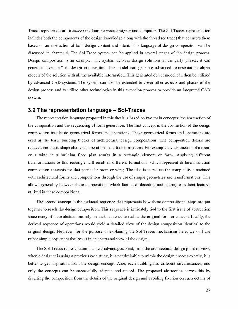
27
Traces representation - a shared medium between designer and computer. The Sol-Traces representation
includes both the components of the design knowledge along with the thread (or trace) that connects them
based on an abstraction of both design content and intent. This language of design composition will be
discussed in chapter 4. The Sol-Trace system can be applied in several stages of the design process.
Design composition is an example. The system delivers design solutions at the early phases; it can
generate “sketches” of design composition. The model can generate advanced representation object
models of the solution with all the available information. This generated object model can then be utilized
by advanced CAD systems. The system can also be extended to cover other aspects and phases of the
design process and to utilize other technologies in this extension process to provide an integrated CAD
system.
3.2 The representation language – Sol-Traces The representation language proposed in this thesis is based on two main concepts; the abstraction of
the composition and the sequencing of form generation. The first concept is the abstraction of the design
composition into basic geometrical forms and operations. These geometrical forms and operations are
used as the basic building blocks of architectural design compositions. The composition details are
reduced into basic shape elements, operations, and transformations. For example the abstraction of a room
or a wing in a building floor plan results in a rectangle element or form. Applying different
transformations to this rectangle will result in different formations, which represent different solution
composition concepts for that particular room or wing. The idea is to reduce the complexity associated
with architectural forms and compositions through the use of simple geometries and transformations. This
allows generality between these compositions which facilitates decoding and sharing of salient features
utilized in these compositions.
The second concept is the deduced sequence that represents how these compositional steps are put
together to reach the design composition. This sequence is intricately tied to the first issue of abstraction
since many of these abstractions rely on such sequence to realize the original form or concept. Ideally, the
derived sequence of operations would yield a detailed view of the design composition identical to the
original design. However, for the purpose of explaining the Sol-Traces mechanisms here, we will use
rather simple sequences that result in an abstracted view of the design.
The Sol-Traces representation has two advantages. First, from the architectural design point of view,
when a designer is using a previous case study, it is not desirable to mimic the design process exactly, it is
better to get inspiration from the design concept. Also, each building has different circumstances, and
only the concepts can be successfully adapted and reused. The proposed abstraction serves this by
diverting the composition from the details of the original design and avoiding fixation on such details of
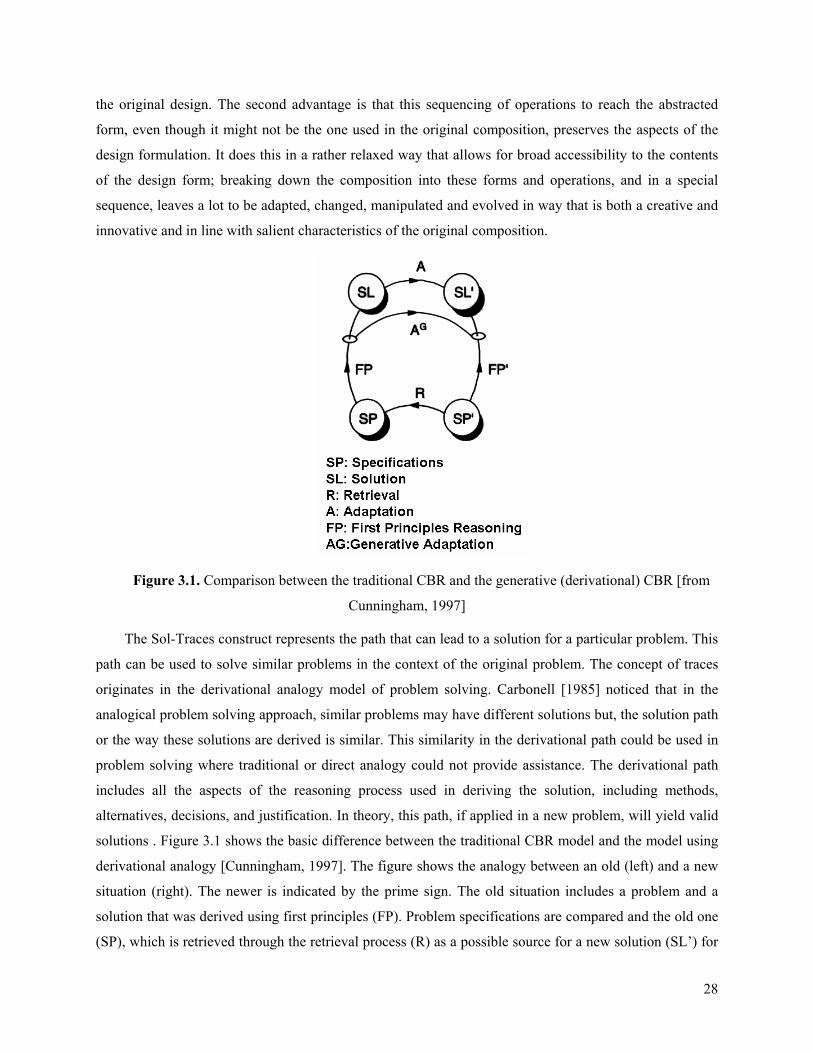
28
the original design. The second advantage is that this sequencing of operations to reach the abstracted
form, even though it might not be the one used in the original composition, preserves the aspects of the
design formulation. It does this in a rather relaxed way that allows for broad accessibility to the contents
of the design form; breaking down the composition into these forms and operations, and in a special
sequence, leaves a lot to be adapted, changed, manipulated and evolved in way that is both a creative and
innovative and in line with salient characteristics of the original composition.
Figure 3.1. Comparison between the traditional CBR and the generative (derivational) CBR [from
Cunningham, 1997]
The Sol-Traces construct represents the path that can lead to a solution for a particular problem. This
path can be used to solve similar problems in the context of the original problem. The concept of traces
originates in the derivational analogy model of problem solving. Carbonell [1985] noticed that in the
analogical problem solving approach, similar problems may have different solutions but, the solution path
or the way these solutions are derived is similar. This similarity in the derivational path could be used in
problem solving where traditional or direct analogy could not provide assistance. The derivational path
includes all the aspects of the reasoning process used in deriving the solution, including methods,
alternatives, decisions, and justification. In theory, this path, if applied in a new problem, will yield valid
solutions . Figure 3.1 shows the basic difference between the traditional CBR model and the model using
derivational analogy [Cunningham, 1997]. The figure shows the analogy between an old (left) and a new
situation (right). The newer is indicated by the prime sign. The old situation includes a problem and a
solution that was derived using first principles (FP). Problem specifications are compared and the old one
(SP), which is retrieved through the retrieval process (R) as a possible source for a new solution (SL’) for

29
the new problem specifications (SP’). A new solution can also be derived using the first principles (FP’),
however a more efficient way is to reuse the analogy to construct a solution from a previous solution to a
similar problem.
There are two models to utilize this analogy; the first is the adaptation (A) of the older solution to fit
the new problem. This includes repairing the older solution in many ways. The analogy here is to the
solution itself. The second model is to look into the problem solving process and reactivate it in the newer
situation. This model is the generative adaptation model (AG) or derivational analogy model. The main
difference is that in the traditional model the adapted solution is reached through the original solution,
whereas in the derivational analogy model the new solution is reached by just reusing the derivational
process. The new solution in the derivational analogy model differs from the old solution, but shares the
derivational process.
Sol-Traces allows for new suggestions, flexible restructuring, and alternatives using the solution
path. If the path was extracted and followed in new circumstances, it would generate a valid solution or
solutions to the new problem. Extracting and representing such a path requires identifying the path along
with all alternatives, decisions, methods, and the reasoning that resulted in this path. We need to represent
the knowledge related to the design problem / solution characteristics (domain knowledge) that allows
activating the trace in the new circumstances. We need to build a system that can read the path from one
problem, apply it within the characteristics of the other problem, and reach decisions and alternatives
using the encoded reasoning in a flexible way. The research approach has been developed to alleviate
these difficulties without losing the benefits of the derivational analogy as described by Carbonell [1985].
The Sol-Traces approach differs from Carbonell’s description in easing the requirements for
structuring these traces and the reasoning encoded within them. There is a semi-representation of that
reasoning or ‘light-weight’ traces. It is a shared approach between the modeled reasoning and the
designer’s actual reasoning and interaction. The derivational path – the Sol-Trace – is a construct that
carries the reasoning process and can be reused - or replayed - to generate a solution for the new problem.
This reuse or replay is achieved through the adaptation/generation mechanisms within the trace, under the
control of the designer. This is carried out in a way that allows different solutions and generations, which
can surprise the designer. Also, similarities between the derivational processes allow them to be
generalized and modeled outside the trace instead of repeating these processes in each trace which makes
the traces less complex whenever possible.
The Sol-Traces representation can be divided into two categories: static representation and
automated (dynamic) representation:

30
1. Static representation: Sol-Traces are represented as static constructs. They can be adjusted,
modified, or adapted, but they remain static in the sense that they will not be reconstructed or
regenerated. The reasoning is stored in the traces as a source of possible alternatives, parameters
that can be changed, or constraints and characteristics of the elements within the trace. The
designer’s input or reasoning is required to complete the process, such as choices or parameters
and the reason behind using them. Sol-Traces are adapted through several processes and new
solutions for the new problem reached through operations such as:
- changing parameters
- adding or deleting elements
- changing locations or topology
- changing constraints or relations
2. Automated representation: Sol-Traces are constructs that can be regenerated. This category
provides deeper reasoning support, which is used in guiding the replay of the trace within the
new problem circumstances. The goal is to have interesting results that are not always easily
predictable by the designer. The regeneration is used to reach a suitable solution for the current
problem and executed to propagate or accommodate changes such as:
- using new parameters, shapes, or location
- accommodating changes in constraints
- replaying with a change in the order of processes, such as sequential, nested, or others
combinations
In the following sections, Sol-Traces are presented with their sources in the architectural domain.
3.3 Design composition with this approach Design composition in architecture involves a wide range of problems and solutions. In this research,
the problem is limited to form generation or design composition. The problem specifications are the
functional requirements and the solution is the assigned form. This problem – solution definition can be
applied to different levels within the architectural design domain, such as the design of a building, a part
of building, or a group of buildings. Architects usually use several different strategies to generate forms.
They master some and continuously learn others throughout their practice. These strategies consist of a
set of tactics, plans, guidelines, or heuristics related to generating or finding these forms.

31
Among the important strategies we focus here on the ones related to the reuse or learning from
previous solutions and the methods or techniques involved in developing them. These embedded methods
and techniques must be identified, extracted, and then adapted to solve new problems. This usually results
in a series of building forms that share some intrinsic characteristics; either generated by the same
designer or by other designers who adopted a similar strategy. In this research, the strategies, the methods,
and techniques, as well as the reasoning they carry are the basis for building Sol-Traces, combining the
representation of strategies for reuse and making use of other strategies found in designs as traces or paths
of the solution. In general, these strategies can be classified as follows:
1. Strategies related to analogies and metaphors: such as direct or indirect analogies to different
kinds of objects or relations
2. Strategies related to shape, geometry and their relationships: shapes such as circle, square,
triangle and relationships such as repetition, similarity, gradation, hierarchy etc.
3. Strategies related to the functional characteristics: such as differentiating between functional
space and circulation space, type of circulation pattern and others
4. Strategies related to type of form organization: such as centralized, linear, radial, clustered, and
grid
5. Strategies related to the use of architectural elements, such as roofs, mass, doors, openings etc.
This research proposes a specific language to capture the essence of these strategies to be used in
representing cases for later reuse and adaptations. These strategies carry the reasoning as rules. They are
applied in cases which provide realizations of these principles or rules. The approach here is to use this
concrete application (cases) and reuse it in similar situation to provide solutions to design problems
without requiring thorough investigation of these rules and details of circumstances for these applications.
The proposed language of composition is based on the work of Wong [Wong, 1993] in his series of
books about principles of form and design. Wong presents a visual language to interpret design. Wong’s
approach is on the formal side of the visual aspects of design; the language and interpretations are based
on systematic thinking with little intuition or emotion. The language proposed here is a subset of Wong’s
visual language elements and operations that are related to form composition. This language provides an
interpretation of the design solutions using basic shapes, geometry, and operations, such as a square as a
shape and gradation of squares in the plan as a design strategy. The interpretation is an abstraction or
reduction of the conceptual idea (or strategy) behind the design solution represented in simple geometrical
shapes and transformations. This abstraction provides the basis for the suggested design composition
model. These components of the language are refined, combined, and further arranged to provide

32
techniques for design composition. The representation is used to index, retrieve, and adapt these
components or their resulting arrangements.
Wong used basic operations such as: Rotation, Reflection, Shifting, Repetition, Gradation, Radiation,
and so on, to describe higher level compositional concepts [Wong, 1993]. This research proposes that any
solution can be generated through variations of these operations. And usually design composition
concepts are translated into these operations. By specifying the design concepts at this lower level of
compositional steps, these concepts can be adapted to fit a new design problem circumstance as if the
original designer was engaged and articulated these modifications. What is lacking in this analogy is that
the original designer does not exist to limit possible alternatives and modifications; hence, more than one
solution can result from these adaptation operations. The system is considered generative in this sense.
3.4 Sol-Traces in architectural design The proposed Sol-Traces can be classified in many different ways. Based on the type of
characteristics that can be extracted from the case, we can distinguish between functional representation,
which deals with the functional characteristics, and the form representation, which deals with form
characteristics. Sol-Traces can be classified into two main types based on the usability or the adaptation
model of the traces. The ‘static’ trace is related to the simple representation and transformational
adaptation. It follows the transformational adaptation model. And the ‘derivational trace’ – or generative
trace is using the derivational analogy model. Other classifications can also be suggested, such as the
dynamic and static types of traces or others to distinguish between the various traces’ characteristics in
this approach. These categories are not exclusive; one trace can carry multiple characteristics from
different categories.
3.4.1 Functional attributes representation A floor plan is a rich representation of many functional aspects of the design as well as other
technical aspects. Not all these aspects can be readily extracted nor are they all suitable for the suggested
visual/attribute-value representation without reduction or abstraction. Functional characteristics are:
• Circulation and use elements: Each space is characterized either as a circulation space or
use space. This abstraction of function plays a crucial role in the composition of a design
solution and provides a design decision and justification. Circulation and use elements can
have several patterns such as linear or circular. Figure 3.2 shows representation of the
circulation and use.
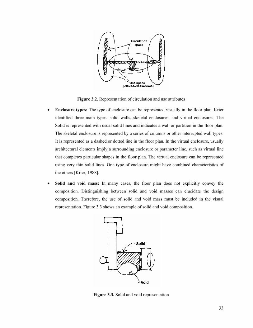
33
Figure 3.2. Representation of circulation and use attributes
• Enclosure types: The type of enclosure can be represented visually in the floor plan. Krier
identified three main types: solid walls, skeletal enclosures, and virtual enclosures. The
Solid is represented with usual solid lines and indicates a wall or partition in the floor plan.
The skeletal enclosure is represented by a series of columns or other interrupted wall types.
It is represented as a dashed or dotted line in the floor plan. In the virtual enclosure, usually
architectural elements imply a surrounding enclosure or parameter line, such as virtual line
that completes particular shapes in the floor plan. The virtual enclosure can be represented
using very thin solid lines. One type of enclosure might have combined characteristics of
the others [Krier, 1988].
• Solid and void mass: In many cases, the floor plan does not explicitly convey the
composition. Distinguishing between solid and void masses can elucidate the design
composition. Therefore, the use of solid and void mass must be included in the visual
representation. Figure 3.3 shows an example of solid and void composition.
Figure 3.3. Solid and void representation

34
• Areas and adjacency: The areas and adjacencies of spaces in the design are abstractions of
the simple geometry that reflects the design elements. Their location preserves their
adjacency in the floor plan. Figures 3.4 show examples of areas and adjacency
representation.
Figure 3.4. Areas and adjacencies representation
• Functional hierarchy and typologies: Two main classifications are proposed for
functional hierarchy: functional hierarchy which represents zonal decomposition of the
design regarding the size and grouping of units and the functional classification of types
without considering any form characteristics. The functional typology is based on
classifications of building typologies such as educational, health, housing etc. The
components of the building model are based on a generic decomposition of building into
spaces, zones, rooms, etc. Also, other classifications such as typological aspects of spaces
can be used such as circulation space vs. use space. Figure 3.5 shows an example of
functional hierarchy representation.
Figure 3.5 Examples of functional hierarchy representations.
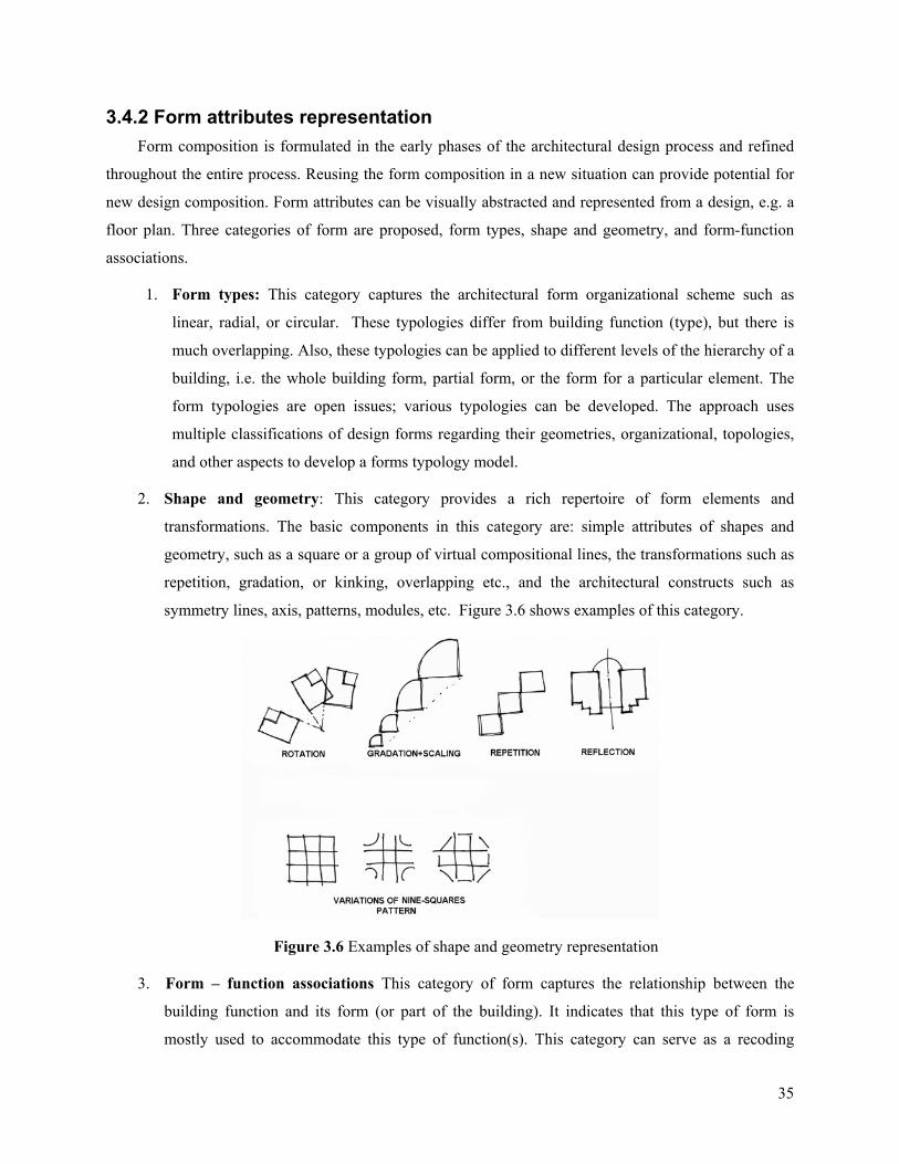
35
3.4.2 Form attributes representation Form composition is formulated in the early phases of the architectural design process and refined
throughout the entire process. Reusing the form composition in a new situation can provide potential for
new design composition. Form attributes can be visually abstracted and represented from a design, e.g. a
floor plan. Three categories of form are proposed, form types, shape and geometry, and form-function
associations.
1. Form types: This category captures the architectural form organizational scheme such as
linear, radial, or circular. These typologies differ from building function (type), but there is
much overlapping. Also, these typologies can be applied to different levels of the hierarchy of a
building, i.e. the whole building form, partial form, or the form for a particular element. The
form typologies are open issues; various typologies can be developed. The approach uses
multiple classifications of design forms regarding their geometries, organizational, topologies,
and other aspects to develop a forms typology model.
2. Shape and geometry: This category provides a rich repertoire of form elements and
transformations. The basic components in this category are: simple attributes of shapes and
geometry, such as a square or a group of virtual compositional lines, the transformations such as
repetition, gradation, or kinking, overlapping etc., and the architectural constructs such as
symmetry lines, axis, patterns, modules, etc. Figure 3.6 shows examples of this category.
Figure 3.6 Examples of shape and geometry representation
3. Form – function associations This category of form captures the relationship between the
building function and its form (or part of the building). It indicates that this type of form is
mostly used to accommodate this type of function(s). This category can serve as a recoding
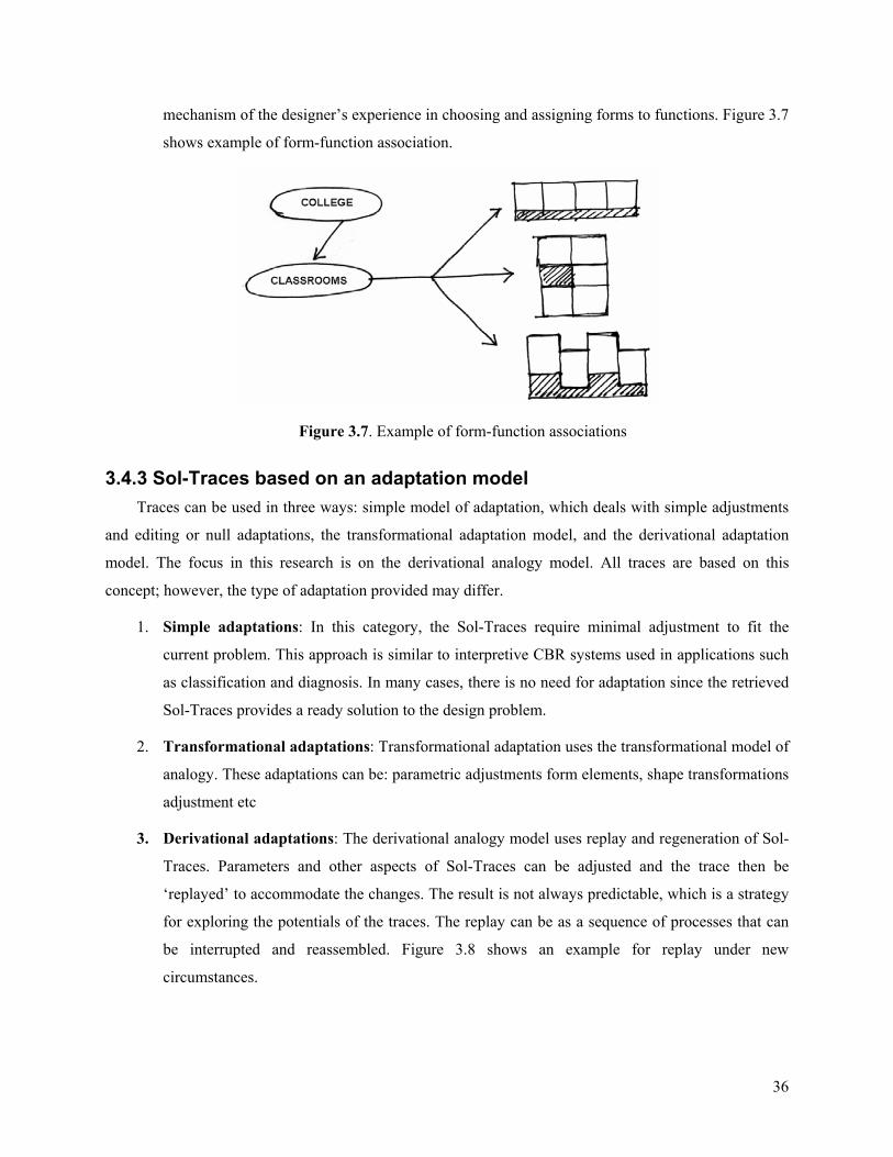
36
mechanism of the designer’s experience in choosing and assigning forms to functions. Figure 3.7
shows example of form-function association.
Figure 3.7. Example of form-function associations
3.4.3 Sol-Traces based on an adaptation model Traces can be used in three ways: simple model of adaptation, which deals with simple adjustments
and editing or null adaptations, the transformational adaptation model, and the derivational adaptation
model. The focus in this research is on the derivational analogy model. All traces are based on this
concept; however, the type of adaptation provided may differ.
1. Simple adaptations: In this category, the Sol-Traces require minimal adjustment to fit the
current problem. This approach is similar to interpretive CBR systems used in applications such
as classification and diagnosis. In many cases, there is no need for adaptation since the retrieved
Sol-Traces provides a ready solution to the design problem.
2. Transformational adaptations: Transformational adaptation uses the transformational model of
analogy. These adaptations can be: parametric adjustments form elements, shape transformations
adjustment etc
3. Derivational adaptations: The derivational analogy model uses replay and regeneration of Sol-
Traces. Parameters and other aspects of Sol-Traces can be adjusted and the trace then be
‘replayed’ to accommodate the changes. The result is not always predictable, which is a strategy
for exploring the potentials of the traces. The replay can be as a sequence of processes that can
be interrupted and reassembled. Figure 3.8 shows an example for replay under new
circumstances.
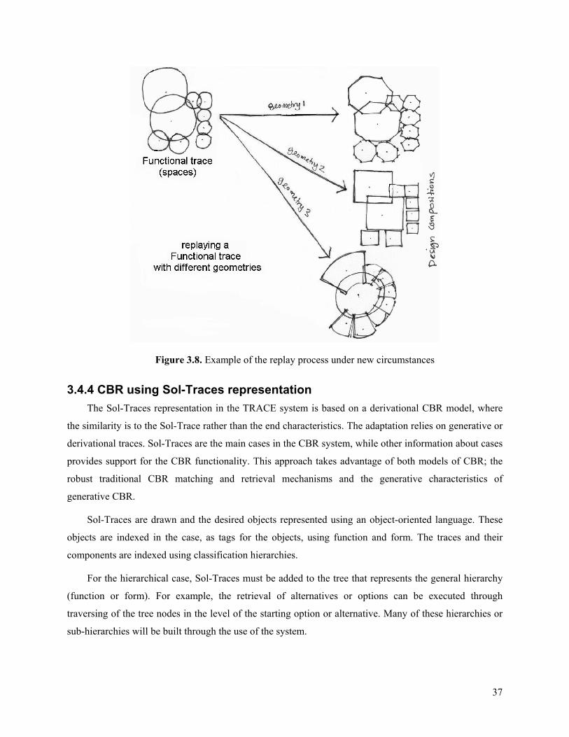
37
Figure 3.8. Example of the replay process under new circumstances
3.4.4 CBR using Sol-Traces representation The Sol-Traces representation in the TRACE system is based on a derivational CBR model, where
the similarity is to the Sol-Trace rather than the end characteristics. The adaptation relies on generative or
derivational traces. Sol-Traces are the main cases in the CBR system, while other information about cases
provides support for the CBR functionality. This approach takes advantage of both models of CBR; the
robust traditional CBR matching and retrieval mechanisms and the generative characteristics of
generative CBR.
Sol-Traces are drawn and the desired objects represented using an object-oriented language. These
objects are indexed in the case, as tags for the objects, using function and form. The traces and their
components are indexed using classification hierarchies.
For the hierarchical case, Sol-Traces must be added to the tree that represents the general hierarchy
(function or form). For example, the retrieval of alternatives or options can be executed through
traversing of the tree nodes in the level of the starting option or alternative. Many of these hierarchies or
sub-hierarchies will be built through the use of the system.
38
The reasoning in Sol-Traces system is divided into two main types: reminding and adaptation.
Reminding is the core function of retrieval in CBR; it is based on general characteristics, functional
characteristics, and form characteristics. The reminding can take place at any time or at any situation
during the use of the system. Reminding can be initiated by the designer or through automated functions.
Reasoning through adaptation can adjust the Sol-Traces in order to fulfill the requirements of the current
problem. This adjustment can be as editing the Sol-Traces, substituting and transforming, or replaying
and regenerating. Sol-Traces must be represented to allow such adaptation. For example, for editing, the
representation provides components and parameters to work on. For replay, the representation provides
trace components that can take certain behavior based on the new circumstances of the replay process.
So far in this chapter, we presented the overview of the Sol-Traces approach in this research. The
chapter starts with presenting a design process model that is envisioned in this research. This is followed
by proposing the aspects of the representation language, the Sol-Traces abstraction. An explanation of
design composition using the approach is presented. The rest of the chapter is devoted to the aspects of
Sol-Traces in architecture. This included the function attribute, the form attributes, adaptation in Sol-
Traces, and finally the integrated CBR using Sol-Traces representation.
39
4. Compositional steps of Sol-Traces
The Sol-Trace approach can be used in many problems in design. The traces contain steps in a
sequence. Since the targeted problem in this thesis is design composition, these steps are referred to as
‘composition steps’. There are many different strategies used in design composition as discussed in the
previous chapters. These strategies are broken down to moves and steps manifested in the process. The
composition steps model these moves in the context of traces. The thesis deals with few of these strategies
as a proof for the use of Sol-Traces in the process. Many other strategies can be modeled using the trace
approach. The strategies used in this thesis are: transformations and formative ideas. Therefore two types
of composition steps are used in traces; the first represents transformation operations and the second
represents formative ideas.
4.1 Transformations Transformations are the first type of composition steps along the trace. Transformations are at the
heart of the abstraction language suggested in this thesis. In design composition transformations provide
mechanism to construct, modify, and adapt design forms. Transformations are used in the context of
traces. The traces approach demands special settings and adaptation of these transformations.
Transformations that can be included in traces are unlimited and traces can be specialized through using a
subset of these transformations. One of the main transformations in traces is the placement process; the
operator ‘add’ which is used frequently in traces to introduce new elements to the composition. Examples
of transformations that can be used in traces are: delete, repeat, shift, rotate, reflect, scale, and grade. Each
composition step from this type carries one of these transformations. These transformations are explained
in the following sections.
4.1.1 Add The add operator is defined as the introduction and placement of a new element to the design. This
element can be either a pre-defined geometrical shape or a user defined shape as a unit form. Add is a
general operation regardless of the specification of the shape to be added. The add operation requires as
parameters two points, as well as the characteristics of the added shape or unit form (parameters). The
first point is defined within the composition plan, and the second point is within the added shape or unit
form. The characteristics of the added shape within the trace are based on the abstraction process of the
case. In the adaptation process, the characteristics of the added shape can be provided either from the
designer or from matching cases that have similar operations. In adaptation, the retrieved shape should

40
match the ratio of the original shape in the case. If it does match within a certain margin, it will be
adjusted by the system before adding. The margin can be defined by the user as a control parameter
within the system.
For example, a focal point in a composition can be a center for adding several shapes. Each shape
has its own insertion point such as its center or corner, or a middle point of an edge or any appropriate
point within the shape. Figure 5.1 illustrates the add operation. It is a case of adding a square shape at the
center of another square, which is selected as a focal point in the composition. The insertion point of the
added square happens to be its center. The characteristics of the added square are derived from the
abstraction of the actual design form. In this case the added square is double the size of the focal square.
A class ‘Add’ accommodates all the aspects of the add operation. Attributes of the class Add and
parameters of the add operator are:
- The shape to be added – including the addition point related to the shape
- The insertion point, either a focal or other point in the composition, or a point on the Sol-
Trace board.
- The area of the shape to be added (if needed)
Figure 4.1. The add adaptation operation
4.1.2 Repeat The repeat operator allows the user to generate duplicates of shapes. It is useful when there are
similar shapes in the design, and unifying them as a repeated shape can enhance the abstraction of the
composition. The class ‘Repeat’ represents the repetition operator. Its attributes and parameters of the
repeat operator are as follows:

41
1. The shape to be repeated. The shape has a special point where the repetition starts from. The
shape must maintain a specific orientation with respect to the repetition axis.
2. Number of repetitions: the number of the generated shapes including the original shape
3. The axis of repetition is defined through the point of repetition and an angle with the positive X
axis.
4. The repetition pitch is the distance between the repetition points and its counterpart in the next
shape along the repetition axis.
In adaptation, the mapped and retrieved repetitions are scaled up or down collectively (including all
their attributes). This enables them to fit the areas specified in the functional diagram of the case.
Retrieving a larger set of repeated shapes may disturb the form composition at hand. Up to a certain
margin this can be acceptable. This margin is defined by the designer as a control variable. In the
mapping process between repetitions, the above mentioned attributes have the following priorities: the
number of repetitions, the angle of axis, the pitch (again, within a margin controlled by the designer),
point of repetition, and shape orientation respectively. Figure 4.9 shows a typical repeat operation for a
set of L-shaped forms. This repetition is along an axis that makes a 30 degree with the X axis. The
orientation of the shapes in this repetition is maintained.
Figure 4.2 The repeat operation
4.1.3 Delete The Delete operator simply erases or eliminates a shape or a component from the design. This
operation takes an argument the component to be deleted, and tracks down all the related effects after the
deletion process. The delete operation is helpful in erasing unnecessary parts that overload the
composition. It is also useful where a certain aspect in the composition is better revealed through the

42
deletion of certain parts. For example, deleting the middle shape of two overlapping squares can reveal
another formation of two L-shaped forms. In some cases new shapes in the formation have to be
identified by the system prior to the delete process. This is done within the abstraction and the trace
building process. In this way, the add operator can be used in detecting emergent shapes with the help of
the abstraction process and the designer’s input. Figure 4.3 shows the deletion process mentioned in this
example.
Figure 4.3 The delete operation
4.1.4 Shift The Shift operator is required to move an element into another location in a parallel movement. Shift
requires as parameters an insertion point in the shape and a new point. It can also be done through a shift
distance or a step and a direction. The shift process differs from repeat in the number of shapes generated.
Usually shift generates no more than two shapes. The default shift is to move the shape but creating
another shifted copy can be requested. The common shifts (or translations) are along the X and Y axes.
The shift process proceeds as follows:
- Calculate the new location in the form of coordinates for the new shape.
- Redraw the adjusted shape.
- If the old shape needs to be retained (a duplicate shifted shape is desired), the process starts
with cloning the old shape and then proceeds as above.
Figure 4.4 shows a typical shift of a square shape. In this case the shift is defined through the old
point and a new translated point. A class ‘Shift’ represents the shift operation and all the required
attributes.
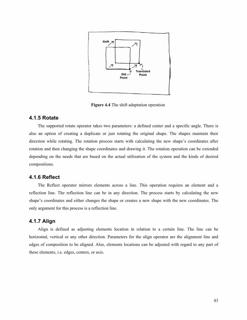
43
Figure 4.4 The shift adaptation operation
4.1.5 Rotate The supported rotate operator takes two parameters: a defined center and a specific angle. There is
also an option of creating a duplicate or just rotating the original shape. The shapes maintain their
direction while rotating. The rotation process starts with calculating the new shape’s coordinates after
rotation and then changing the shape coordinates and drawing it. The rotation operation can be extended
depending on the needs that are based on the actual utilization of the system and the kinds of desired
compositions.
4.1.6 Reflect The Reflect operator mirrors elements across a line. This operation requires an element and a
reflection line. The reflection line can be in any direction. The process starts by calculating the new
shape’s coordinates and either changes the shape or creates a new shape with the new coordinates. The
only argument for this process is a reflection line.
4.1.7 Align Align is defined as adjusting elements location in relation to a certain line. The line can be
horizontal, vertical or any other direction. Parameters for the align operator are the alignment line and
edges of composition to be aligned. Also, elements locations can be adjusted with regard to any part of
these elements, i.e. edges, centers, or axis.
44
4.1.8 Scale Scale can be applied to any element or unit form. It requires as parameters a scaling factor and a base
point. If a base point is not defined, the process will use the center of the shape as the base point. Scaling
can be done in multiple steps. For instance scaling a square into a larger one can proceed through four
intermediate squares. This might be required in some cases to emphasize the scale process in the
composition. New shapes are created as these steps shown or only the modified shape’s coordinates are
being drawn in the composition. Also there is the option of keeping or deleting the original scaled shape.
4.1.9 Grade There are two forms of the grade operator: grading the shape or the size of an element. For instance,
a square can be graded into an octagon though grading its corners into diagonal edges. A segment of line
can be considered as a compressed rectangle and graded into a larger one through increasing the size.
4.2 Formative ideas (F.I.) ‘Formative ideas’ is the strategy used and employed as the second type of compositional step along
the traces. Formative ideas play an important role in building traces. Formative ideas are ideas or concepts
utilized in formulating design compositions [Clark & Pause, 1996]. Usually they reflect a dominant
relationship between parts, specific geometric aspects, configuration patterns or other standing features of
the composition. In design communities, a formative idea is generally referred to as a design concept that
can be found in several similar designs. Generalizing these formative ideas is done by design theoreticians
and presented in design composition text books [Clark & Pause, 1996; Krier, 1988].
To be used in computation of design composition, these formative ideas have to be adapted to the
specific tasks they are intended to perform. In the TRACE system, a set of formative ideas was developed
from Clark and Pause’s book, which provides one of the widest classifications of design precedents,
particularly for compositional aspects [Clark & Pause, 1996]. The set was chosen to match the
functionality of the TRACE system and to best present system capabilities. They are used to perform two
main tasks. Firstly, they are utilized in classifying cases and traces using a vocabulary that most designers
are familiar with. Secondly they are used to provide adaptations of design states at the trace nodes. The
set of formative ideas is an example of classifications that can be used in the TRACE system.
Regarding the participation of formative ideas in form generation and adaptation within traces, they
can be divided into two categories. The first is focused on descriptions for indexing and retrieval of cases
and traces. Examples of this category are: ‘Unit to whole’, ‘symmetry and balance’, and ‘configuration
patterns’. This category can also be used in form generation in some cases. The second category is
intensively used in form generation through substitution with retrieved variations in the trace as options.

45
These options are from the same formative idea. Examples of this category are: ‘geometry and grid’,
‘progression’, and ‘reduction’.
Formative ideas are used to classify design cases. The main categories of formative ideas may have
several levels of sub-categories of design composition ideas. These sub-categories usually group together
close variations of the category at a finer level. For instance the group of geometric formative ideas can
have a sub-group of “square variation” which in turn can be divided into groups such as “2-square”, “4-
square”, and “9-square” formations. A design case that utilizes one formative idea or its sub-categories
will be a member of that category through having a “case-tag” that relates the case to this particular
category.
Cases provide detailed implementations of the concept covered in the formative idea category or
sub-category. This is done through the filled parameters of the formative idea, in other words, through the
use of dimensions and ratios in the cases that reflect this idea. Also, a design case can be a member of one
or more categories or even none of the categories.
The match starts at the last subcategory and propagates up to the main formative idea. For example,
the parameters of a case with 4-square geometry can be retrieved and applied in another situation where
the 4-square geometry is used. If there is no 4-quare match, 9-square geometry might be tried, or even the
general square configuration can be retrieved from other cases. Specific handlers can be used throughout
the formative idea subcategories to assure the applicability of the retrieved match from different levels in
the formative idea hierarchy. However, this might not be needed if the formative idea itself can be
contained in one level of hierarchy.
In the TRACE system, a formative idea can be developed through one or more steps (nodes) along
the trace. In the adaptation/exploration process, when a formative idea is being replaced, all the steps are
replaced at the same time. The location of the start of the formative idea development along the trace is
marked and the replacement should start at that point.
Formative ideas contain handlers to control their interchangeability and to allow for more flexible
and unexpected results. This means that different formative ideas at one level might be exchangeable to a
certain degree, besides the multi-level ideas exchangeability that is mentioned above. Both the trace and
the case indicate the formative ideas that they contain. This facilitates the matching and retrieval process.
Examples of formative ideas are listed below, four of them are descriptive ideas and three are form
generation ideas. For complete and illustrated explanation of formative ideas refer to [Clark and Pause,
1996]:
46
- Unit to whole is a descriptive formative idea relating units or shapes in the composition
and their relation to the whole composition.
- Symmetry and balance is descriptive formative idea detecting the symmetry and balance
relations in the composition.
- Repetitive to unique is a descriptive formative idea detecting the repetitions of forms in the
composition and the unique forms.
- Configuration pattern is a descriptive idea classifying the form patterns.
- Geometry and Grid is a form generation idea. It provides mechanisms for transforming the
underlying schema of the form and to introduce order to the composition
- Reduction is a form generation idea detecting scaling or grading of composition elements.
- Progression is a form generation idea detecting hierarchy, transition, and transformations
in the composition.
Three examples of these formative ideas will be explained in more detail below:
4.2.1 Unit to Whole This F.I. represents the compositional aspects of using a specific unit in the form and its relation to
the whole form. The unit-form is usually a dominant geometric formulation that is manifested in many
views of the whole form. The whole form itself can be a scaled version of the unit-form or doubling or
with other relations.
4.2.2 Repetitive to unique In this F.I. the relationship between the unit-form and the whole is between being unique and
complete repetition. Several compositions can be developed solely by repeating the unit-form in different
ways. Also, a specific unit-form can be added to the composition in order to focus on creation element or
function.
4.2.3 Geometry (and Grid) Geometry is one of the main sources of concepts in form compositions. Geometry covers all the
aspects of the form such as the dominant or embedded geometrical shapes and the underlying grid system.
The geometry can be divided into subcategories such as:
- Basic geometry
- Squares (2, 4, or 9 square geometry), square and circle.
47
- Rectangular overlapped by a circle, 1.4 and 1.6 rectangular.
- Geometric derivatives
- Rotated shifted and overlapped.
- Pinwheel, radial, and Spiral
- Grid
In this chapter the compositional steps of the trace are explained. Two main types of steps are used in
this research. Other type may be added in later developments. These two types represent two main
strategies in design composition. The first type of compositional steps is transformations.
Transformations include the ADD operator and other operators such as REPEAT, SHIFT, and REFLECT.
Each com position step of this type carries one transformation. The second type of steps explained in this
chapter is the formative ideas. These are design concepts utilized in the composition. Each step in this
type carries a specific application of a formative idea. Other variations that can be drawn from the same
formative idea can be found in other traces and can be retrieved and reused. The trace can have any
combination of these compositional steps types and these steps are the building blocks of traces that
represent design compositions.

48
5. Cases and Sol-Traces in the TRACE system
This chapter introduces two central representation structures in TRACE: the case and the Sol-Trace.
Cases in the TRACE system represent design knowledge covering different levels in the design process.
The first level is cases as architectural compositions or solutions for buildings. These cases are presented
as floor plans and other architectural representations. At this level, the design composition is retrieved for
the designer as a complete case. Cases have other characteristics or attributes that are used in matching
and retrieval, such as the type of the building, the size, number of occupants, or form characteristics of the
composition.
The second level of design knowledge represented in the TRACE system is the level of design
composition components and strategies – the Sol-Traces level. Knowledge at this level describes
elements, moves, or processes that are introduced to the composition at each step of the trace. Cases in
this second level are similar situations in the design composition process that can be mapped, retrieved,
and reused in solving or adapting other design compositions.
The following two sections describe cases and their components. Section 5.1 is devoted to the first
level of design knowledge and will be referred to as cases. Section 5.2 deals with the second level – the
Sol-Traces. Section 5.3 discusses how cases are classified and indexed. This will be followed by the
discussion of case abstraction and acquisition processes in 5.4.
5.1. Case representation This section presents cases and their components. The case components are the architectural
representation, case attributes, form and function diagrams, and the Sol-Trace.
Cases and their representation is the core of any CBR system. Each case describes a problem and a
solution. In TRACE, the case describes either a real building or merely a design. The design problem is
represented in the form of desired functional and form characteristics or requirements. The
solution/outcome of a case is the most valuable part of the case. In the TRACE system, the solution is
represented as Sol-Trace. Figure 5.1 shows the elements of a case.
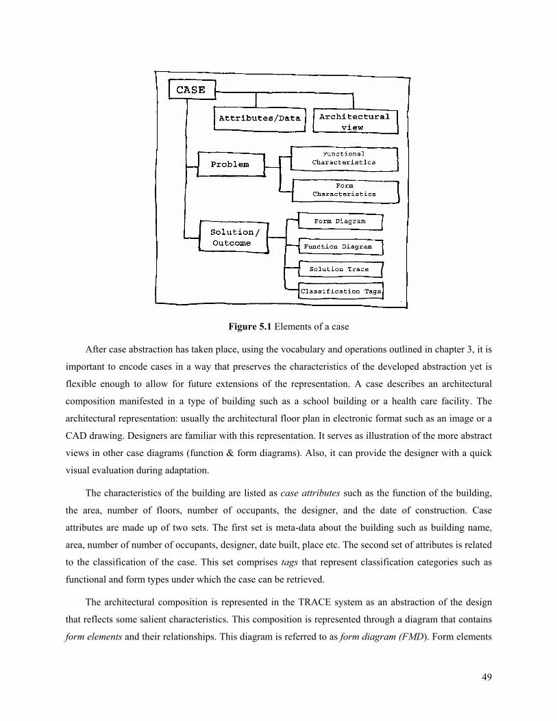
49
Figure 5.1 Elements of a case
After case abstraction has taken place, using the vocabulary and operations outlined in chapter 3, it is
important to encode cases in a way that preserves the characteristics of the developed abstraction yet is
flexible enough to allow for future extensions of the representation. A case describes an architectural
composition manifested in a type of building such as a school building or a health care facility. The
architectural representation: usually the architectural floor plan in electronic format such as an image or a
CAD drawing. Designers are familiar with this representation. It serves as illustration of the more abstract
views in other case diagrams (function & form diagrams). Also, it can provide the designer with a quick
visual evaluation during adaptation.
The characteristics of the building are listed as case attributes such as the function of the building,
the area, number of floors, number of occupants, the designer, and the date of construction. Case
attributes are made up of two sets. The first set is meta-data about the building such as building name,
area, number of number of occupants, designer, date built, place etc. The second set of attributes is related
to the classification of the case. This set comprises tags that represent classification categories such as
functional and form types under which the case can be retrieved.
The architectural composition is represented in the TRACE system as an abstraction of the design
that reflects some salient characteristics. This composition is represented through a diagram that contains
form elements and their relationships. This diagram is referred to as form diagram (FMD). Form elements
50
diagram (FMD) is a diagram that puts the form elements together. It has the geometry that organizes these
elements as well as other form constructs such as lines and grids. The case is classified by the
characteristics of this form diagram and the corresponding functional attributes (see figure 5.2).
Elements in the FMD usually have architectural functions. For each form element, its architectural
function is represented through a proxy element referred to as function element, which carries the
functional characteristics such as the area, the functional type of the element (“classroom” type) and
others. Topological relationships among these functional elements are preserved through a diagram
referred to as the functional diagram (FND) (see figure 5.2) Functional elements diagram (FND) is a
diagram that arranges the functional elements in their original places (in the floor plan) with reference to
their relative positions. The diagram preserves adjacency and other spatial relationships among these
elements. Functional elements are presented through geometric shapes such as circles, lines, and squares.
These simple shapes have centers matching the calculated centers of gravity of the more complex original
shapes that they stand for, and with area equal to the original areas. An element in the FND can represent
several levels of the buildings functional hierarchy, for instance, a single classroom in a college building,
a classroom combined with its services, or a cluster of classrooms. In the case, a class “Case Board”
collects this information. The FND is a virtual representation behind the form representation. It is used for
undertaking any functional related interactions such as query, search, or retrieval. Other characteristics
can be associated with these functional elements such as use vs. circulation, solid and void, virtual, solid,
or skeletal enclosure and others.
The derivation of the design composition in the case is represented through the Sol-Trace. The Sol-
Trace is a construct within the case that enables adaptation and reuse of the design composition. The Sol-
Trace is a sequence of operations and elements introduced step by step ending with the complete case
composition. Steps in the Sol-trace are classified based on their parameters. These steps are subject to
mapping and retrieval between Sol-Traces in different cases.
After retrieving a case, the TRACE system presents a view of the case to the designer. As in Figure
5.2 the case starts with the architectural floor plan and contains the required details. This floor plan allows
the user to clearly understand the abstracted diagrams underneath; the functional diagram (FND) and the
form diagram (FMD). Both these layer diagrams are presented in simple abstracted geometry.
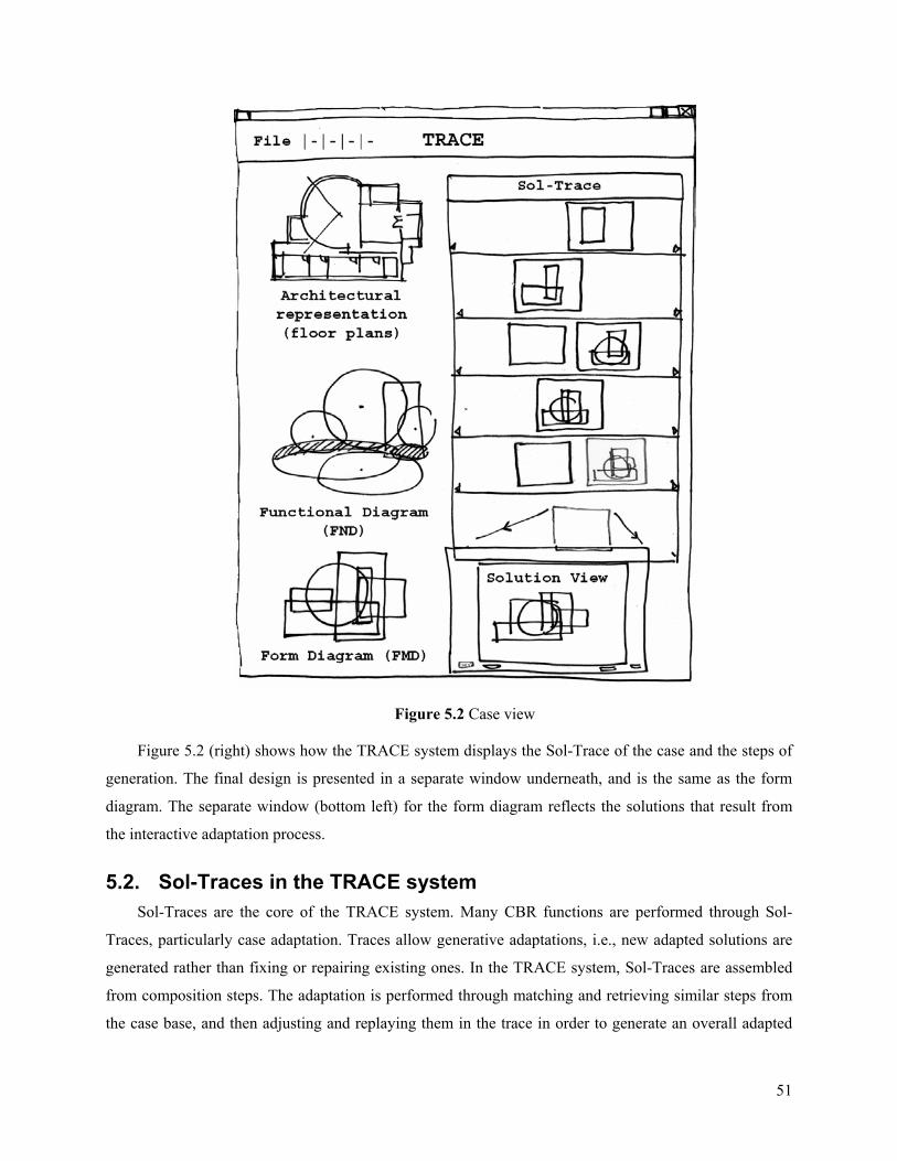
51
Figure 5.2 Case view
Figure 5.2 (right) shows how the TRACE system displays the Sol-Trace of the case and the steps of
generation. The final design is presented in a separate window underneath, and is the same as the form
diagram. The separate window (bottom left) for the form diagram reflects the solutions that result from
the interactive adaptation process.
5.2. Sol-Traces in the TRACE system Sol-Traces are the core of the TRACE system. Many CBR functions are performed through Sol-
Traces, particularly case adaptation. Traces allow generative adaptations, i.e., new adapted solutions are
generated rather than fixing or repairing existing ones. In the TRACE system, Sol-Traces are assembled
from composition steps. The adaptation is performed through matching and retrieving similar steps from
the case base, and then adjusting and replaying them in the trace in order to generate an overall adapted
52
solution. Therefore, the adaptation process is a continuous retrieval and replay of variations of solution
steps. Many adapted solutions can be generated in this process and a solution optimization technique can
then be used to refine the selection of best fit solution.
5.2.1. The concept of Sol-Traces The trace is a path through a sequence of states of the design composition. The trace progresses from
one state to another through composition steps. Each composition step introduces an operation or a
change. The outcome of the step is reflected in the next state. Progress through these steps continues until
a complete abstracted form of the design composition is reached – equivalent to the FMD. The trace is
represented through a tree structure that begins with the root (the start state) and ends with a final state
that represents the completed design composition. Each solution represents a unique generation path
within the tree. Several paths can be generated and stored in the tree.
The essential concept behind the use of traces is that through altering states and/or selecting different
operations, locally at a composition step, the trace generates a different solution. These alterations of
states come from the use of matched or desired options retrieved from mapping this particular step(s) to
similar situations stored in previous solutions. Through this cycle of mapping and retrieval a new solution
is generated that will be better suited for the new design problem. The roots of this concept lie in the
derivational analogy approach where the analogy is not to the solution but to the way it was derived. The
use of this analogy, in the new situation, transfers to the current problem the mechanisms that were used
in similar previous problems to achieve certain objectives. Running these techniques again, under the new
design problem specifications, generates adapted solutions.
Each step of the trace introduces a change to the state of the design. This change can be through the
introduction of a new element, operation, or constraint applied to the state. For example aligning
components to a certain line or axis is an introduced change that affects the composition. The change can
be also through adopting or overlaying a different formative idea such as an underlying grid or module
structure.
5.2.2. Sol-Traces representation The trace is a construct that is built within the case and represents the case’s core composition. It
models how the design solution may have been, or could have been, generated. This does not imply that
the system infers design intent nor does it represent the rationale behind design decisions. Rather, the idea
is to analyze the solution in the case and represent it with a language of operations and elements,
assembled as a sequence of basic components of the trace, which ends with the manifested solution in the
case.
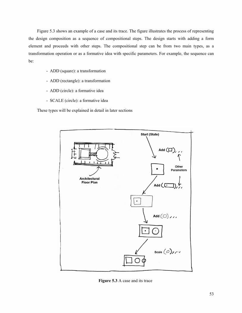
53
Figure 5.3 shows an example of a case and its trace. The figure illustrates the process of representing
the design composition as a sequence of compositional steps. The design starts with adding a form
element and proceeds with other steps. The compositional step can be from two main types, as a
transformation operation or as a formative idea with specific parameters. For example, the sequence can
be:
- ADD (square): a transformation
- ADD (rectangle): a transformation
- ADD (circle): a formative idea
- SCALE (circle): a formative idea
These types will be explained in detail in later sections
Figure 5.3 A case and its trace

54
Computationally, the trace is represented as a tree data structure. As shown in Figure 5.4, the root of the
tree is the starting point of the solution. Edges of the tree represent the specific composition steps of the
trace. The nodes are the results of introducing these steps. Nodes and their branches form tree levels. The
number of levels depends on the length of the sequence of branches and nodes required to generate the
solution. The node can have more than one branch or option branching out of it. The node represents a
design state which is the result of introducing the previous trace step. The trace is the path from root to
the end of the farthest level (a leaf). Each edge can represent a single operation, or a set of operations and
transformations bundled together under a specific description to be called “option”. (The current
implementation is limited to one change or transformation at each step). The tree structure allows for
flexible branching, accommodating different options at the nodes and for generating different solutions
and storing them within the tree.
Figure 5.4 A Sol-Trace diagram
At each node, the trace can proceed with the original step or, alternatively, one of the options stored
within the trace. The designer may introduce a change in one of the following ways:
- Designer adjusts parameters of the operation or constraint.
- Designer applies a different structure (transformation operation or formative idea): in this
case the designer manually chooses between available or applicable structures. This change
55
can range from simple substitution of shapes to completely changing the original
compositional structure.
- Designer asks the system to fill the options according to specified criteria. The criteria can be
introduced automatically by the system identifying a discrepancy between the retrieved case
and the current design problem, or by the designer adjusting the query to fit current needs.
These criteria may be based on functional or form attributes.
5.2.3. Sol-Trace ‘Composition Steps’ Composition steps are the core ingredients of the traces. Each step entering the trace node is
associated with one or more of composition operations. The Sol-Trace is the result of applying the
sequence of these steps. The operation can be extended, added, or redefined to allow building an accurate
and representative trace. As presented in the previous chapter, two types of composition steps are used in
the TRACE system:
• Transformation operations: such as addition, rotation, reflection, shifting and repetition,
gradation, radiation.
• Introducing Formative ideas (F.I): This includes schematic changes such as introducing a
grid or a module system, or overlapping a circle and a rectangle. These formative ideas in
the domain of architectural composition.
5.2.4. Sol-Trace ‘Options’ Options indicate possible inputs that change/alter the design state at each decision point throughout
the Sol-Trace. Options are associated with composition steps of the trace. They can be retrieved from
other traces and incorporated within the current trace at each step. Options simulate the choices that the
designer was facing when developing the original design, or the theoretically available variations for each
step. By exploring these options, the design composition can be adapted to fit new needs which did not
exist at the time of the original design. Retrieving and selecting the options to run within the trace is an
important task in the TRACE system. This task is handled by the Sol-Traces engine (STE) which works
on the Sol-Trace tree and can guide the choice of which options to include and which route the trace
follows between these options.
The Sol-Trace of a case is built from options leading to the solution available in the case. Besides the
options actually used in the trace, other options discovered or identified at the time the trace is built can
also be added to the trace for later use. New solutions can be generated by selecting one or more of the
new options available at the trace nodes or retrieved from the case base. Also, by altering the sequence of
56
the operations, i.e., switching nodes, new solutions can be generated. Options can also be changed or
edited by the designer, which creates new options and generates new solutions. Eventually the trace
representation becomes a path through branches of a tree that holds several paths (solutions). This process
of generating different solutions within the tree and keeping records of them is handled by the Sol-Traces
Engine (STE). New traces that yielded interesting or desired solutions for the problem at hand can be
saved in the case base as new cases if the designer so desires.
There are different ways to incorporate the retrieved or created options in the main replay of the
trace. A first way is to run only one option at a time and record the resulting solution. A second way is to
combine several options, usually selected by the designer or the STE according to specific criteria. A third
way is to run the trace with all possible combinatorial branches, record the solutions, and then select from
them according to specific criteria. A fourth way is that the trace itself can change the sequence of the
branches along the path which can result in rather diverse solutions but with complex tracking of them.
5.2.5. Sol-Trace Handlers In order to utilize a different option at a certain node, the new option must be applicable to the
situation at hand. For example, rotating a form with a certain angle around a center point implies the
presence of a center point in the form at that node. To apply the same operation using another form, that
form must also have a center point available. In the TRACE system, such a center point or other
controlling constructs are called “handlers”. Handlers are present at each trace node to control the
applicability of new or imported options. Handlers organize the application of operations throughout the
trace by providing guides for these operations at each node. Handlers also control the applicability of
options throughout the whole trace. These are called ‘trace’ or ‘global’ handlers.
5.2.6 Sol-Trace root and nodes The trace is represented in a tree structure. The root of the tree carries global information about the
trace, which can be used in retrieving the trace and in quick matching of types of compositional steps on
the trace. For example, if there is a composition step of ‘repetition’, this will be indicated in the trace root.
The trace root then can be scanned quickly to find out if there is a repetition step in its sequence.
The trace root also provides other information that is required when searching and matching for the
overall characteristics of the design form manifested in the trace. These characteristics can be directly
connected to the compositional steps or can be induced from these steps and their attributes. For instance,
if a desired characteristic of a form is to have ‘gradation’, then the trace with a step of gradation in its
sequence should be retrieved. On the other hand, if the desired characteristic of the form was to have a
specific ‘ratio’ then the attributes of all compositional steps of the trace must be checked for that ratio.
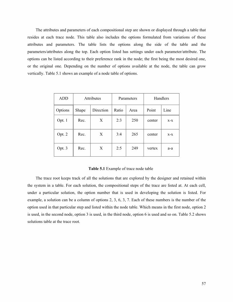
57
The attributes and parameters of each compositional step are shown or displayed through a table that
resides at each trace node. This table also includes the options formulated from variations of these
attributes and parameters. The table lists the options along the side of the table and the
parameters/attributes along the top. Each option listed has settings under each parameter/attribute. The
options can be listed according to their preference rank in the node; the first being the most desired one,
or the original one. Depending on the number of options available at the node, the table can grow
vertically. Table 5.1 shows an example of a node table of options.
Table 5.1 Example of trace node table
The trace root keeps track of all the solutions that are explored by the designer and retained within
the system in a table. For each solution, the compositional steps of the trace are listed at. At each cell,
under a particular solution, the option number that is used in developing the solution is listed. For
example, a solution can be a column of options 2, 3, 6, 3, 7. Each of these numbers is the number of the
option used in that particular step and listed within the node table. Which means in the first node, option 2
is used, in the second node, option 3 is used, in the third node, option 6 is used and so on. Table 5.2 shows
solutions table at the trace root.
ADD Attributes Parameters Handlers
Options Shape Direction Ratio Area Point Line
Opt. 1 Rec. X 2:3 250 center x-x
Opt. 2 Rec. X 3:4 265 center x-x
Opt. 3 Rec. X 2:5 249 vertex a-a
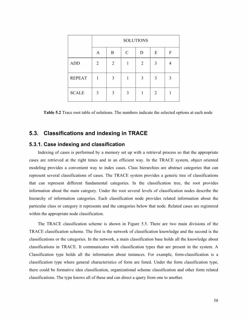
58
Table 5.2 Trace root table of solutions. The numbers indicate the selected options at each node
5.3. Classifications and indexing in TRACE
5.3.1. Case indexing and classification Indexing of cases is performed by a memory set up with a retrieval process so that the appropriate
cases are retrieved at the right times and in an efficient way. In the TRACE system, object oriented
modeling provides a convenient way to index cases. Class hierarchies are abstract categories that can
represent several classifications of cases. The TRACE system provides a generic tree of classifications
that can represent different fundamental categories. In the classification tree, the root provides
information about the main category. Under the root several levels of classification nodes describe the
hierarchy of information categories. Each classification node provides related information about the
particular class or category it represents and the categories below that node. Related cases are registered
within the appropriate node classification.
The TRACE classification scheme is shown in Figure 5.5. There are two main divisions of the
TRACE classification scheme. The first is the network of classification knowledge and the second is the
classifications or the categories. In the network, a main classification base holds all the knowledge about
classifications in TRACE. It communicates with classification types that are present in the system. A
Classification type holds all the information about instances. For example, form-classification is a
classification type where general characteristics of form are listed. Under the form classification type,
there could be formative idea classification, organizational scheme classification and other form related
classifications. The type knows all of these and can direct a query from one to another.
SOLUTIONS
A B C D E F
ADD 2 2 1 2 3 4
REPEAT 1 3 1 3 3 3
SCALE 3 3 3 1 2 1

59
Figure 5.5. Classification scheme in the TRACE system
The classifications or the categories themselves are the second part of the TRACE classification
scheme. They hold all the categories that cases can subscribe to. In this way, they form an indexing
mechanism for cases, which allows direct retrieval of desired cases by searching only in the related
category(s).
Another aspect of the TRACE classification scheme is that case indexing is separate from case
storage. This is for two important reasons. The first is that different indexing schemes allow efficient
retrieval of cases and can be added as needed to the system in later refinements. For example, the
formative ideas modeled in the system are among these classifications. Other formative ideas can be
added later to the system to allow retrievals that are convenient to a particular type of design problems.
The second reason is that these indexes can be built without concern for how and where cases are stored.
This allows the TRACE development to focus on indexes for problem solving rather than convenience for
case storage. Figure 5.5 illustrates the generic tree of classification and the hierarchy of nodes.
60
Cases are classified through an indexing scheme that allows each case to hold tags of its
classification memberships as part of the case attributes. The class Case holds these tags - classification
objects - in an expandable container. Several tags can be assigned to a single case to indicate that the case
belongs in classification hierarchies. Classification hierarchies are related to function, form, or other case
characteristics. These hierarchies (indexes) are encoded into the system by an administrator or librarian.
The user can also introduce new classification categories with their own hierarchies as needed.
A case can be indexed using any of its contents, particularly the form and function diagrams. This
allows the retrieval of the case (or part of it) whenever it is helpful in solving the current design problem.
Matching usually starts at the lowest level within the classification hierarchies, and propagates to upper
levels if no cases match at the same level (nearest neighbor retrieval strategy). Each case knows its
location in a specific hierarchy through hosting a classification object – tag - of the certain ‘type’ in that
particular hierarchy. For example, a college of fine arts in a certain university (i.e. CFA at CMU) has a
classification object of type ‘College’, which knows its location within a hierarchy of educational
building and university building respectively as these are the super-classes of that class of ‘college’
5.3.2. Representation of case classification in TRACE At the top level of TRACE classification scheme, and as shown in Figure 5.5, a main class
“Classifications” represents the classification base and holds the information about any classification
introduced within the system. This class has a container, i.e., a linked list that holds the new objects of
classifications. The class also provides methods to add, modify, or delete a classification. There are also
methods to allow tracking and switching from one classification object to another in order to respond to
certain queries and to synchronize between queries. This class holds the knowledge base for the TRACE
system about the design composition domain and all the related classifications.
Before desired classifications can be added, they must be instantiated from a classification type. The
ClassificationType class – abstract class or interface - provides the general specifications for any
classification desired throughout the TRACE system. Specialized types of classifications extend this
class, for example FormClassifications class, or STSClassifications, or OptionClassifications etc.
Instances of these specialized classifications serve as roots for classification category(s). For instance, as
shown in Figure 5.6, a formative idea classification – such as a nine squares formulation - is an instance
of the FormClassifications class and has a tree of categories underneath. The instances know each other
through the classification network and the top Classifications class holds records of new instantiated
classifications and how to get to them. For example, FormClassifications class can be instantiated more
than once to classify several form related characteristics. The FormClassifications class knows how many
of these instantiated and what their functions are. As shown in the same Figure 5.6, under the root, a
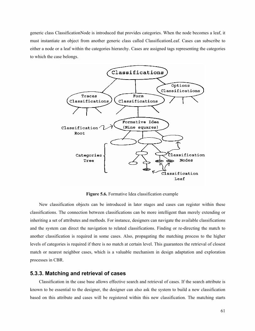
61
generic class ClassificationNode is introduced that provides categories. When the node becomes a leaf, it
must instantiate an object from another generic class called ClassificationLeaf. Cases can subscribe to
either a node or a leaf within the categories hierarchy. Cases are assigned tags representing the categories
to which the case belongs.
Figure 5.6. Formative Idea classification example
New classification objects can be introduced in later stages and cases can register within these
classifications. The connection between classifications can be more intelligent than merely extending or
inheriting a set of attributes and methods. For instance, designers can navigate the available classifications
and the system can direct the navigation to related classifications. Finding or re-directing the match to
another classification is required in some cases. Also, propagating the matching process to the higher
levels of categories is required if there is no match at certain level. This guarantees the retrieval of closest
match or nearest neighbor cases, which is a valuable mechanism in design adaptation and exploration
processes in CBR.
5.3.3. Matching and retrieval of cases Classification in the case base allows effective search and retrieval of cases. If the search attribute is
known to be essential to the designer, the designer can also ask the system to build a new classification
based on this attribute and cases will be registered within this new classification. The matching starts
62
from the exact category. If there are no matching cases, the nearest neighbor will be examined. The
nearest neighbor in this case can be the next leaf or an upper node in the hierarchy. The designer can issue
a query that includes some attributes and parameters of a composition step. The designer can also
introduce changes to these attributes/parameters such as a different area or ratio to fit the new problem. In
future developments of trace, the system can automatically detect discrepancies between the current
problem specifications and the attribute/parameters and adjust the query accordingly.
Although the solutions provided by the system are mainly form compositions, functional
classifications can also be used to retrieve cases. This allows diversity of cases retrieved and ensures
compatibility with functional requirements. The criteria that can be used for matching include:
- Functional elements and their numbers
- Areas – overall and specific elements
- Characteristics of the functional diagram representation itself, which can be linear, widely-
clustered or densely-clustered.
- The average distance between the centers of functional elements.
5.3.4. Classifications of traces As core constructs in the TRACE system, Sol-Traces can be classified according to the
characteristics and behavior they exhibit. Also, Sol-Traces can be classified and indexed using
outstanding characteristics or components related to their options. Sol-Traces can be retrieved directly
from cases (or outside cases) to examine them and potentially use them as a starting point for the design.
Cases can also be retrieved based on their Sol-Traces characteristics. For instance, a particular option on a
Sol-Trace can be used to access several cases that carry Sol-Traces with similar options.
Sol-Traces classifications are instantiated as a ‘Sol-Traces classification type’ object of the class
“STSClassifications”. This main class keeps track of all instances and allows communication between
them. The designer can classify particular traces with a new index, and existing attributes that match the
new index can be used to populate the classification index with Sol-Traces from cases in the case base.
The matched traces are delivered to the designer, as interesting unpredictable results, for further
exploration and possible adaptation and reuse.
5.4. Abstraction of cases and Sol-Traces - case acquisition This process is usually the responsibility of the librarian. In addition, designers, during the use of the
system, can retain new or adapted cases in the case base. This adding and indexing of cases is flexible.
The designer must identify the key compositional features in cases which can be assembled in a dynamic
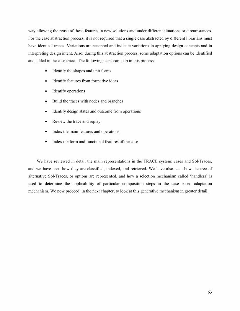
63
way allowing the reuse of these features in new solutions and under different situations or circumstances.
For the case abstraction process, it is not required that a single case abstracted by different librarians must
have identical traces. Variations are accepted and indicate variations in applying design concepts and in
interpreting design intent. Also, during this abstraction process, some adaptation options can be identified
and added in the case trace. The following steps can help in this process:
• Identify the shapes and unit forms
• Identify features from formative ideas
• Identify operations
• Build the traces with nodes and branches
• Identify design states and outcome from operations
• Review the trace and replay
• Index the main features and operations
• Index the form and functional features of the case
We have reviewed in detail the main representations in the TRACE system: cases and Sol-Traces,
and we have seen how they are classified, indexed, and retrieved. We have also seen how the tree of
alternative Sol-Traces, or options are represented, and how a selection mechanism called ‘handlers’ is
used to determine the applicability of particular composition steps in the case based adaptation
mechanism. We now proceed, in the next chapter, to look at this generative mechanism in greater detail.

64
6. Generative adaptation of traces
Adaptation is an essential component of a problem-solving case based reasoning system. The
TRACE system adopts a generative adaptation approach that fits the domain of design composition as
described in chapter 3. Generative adaptation in TRACE is performed through replaying a Sol-Trace to
accommodate changes or adapted steps of the trace. Adaptation of these composition steps is at the core
of this generative approach.
The generative adaptation of the trace in TRACE system is achieved through changes in the design
state along the trace or the solution path. This change is done through design composition strategies or
moves applied at each step. Two strategies with specific attributes and parameters control the design
elements as well as their placement and manipulation. These adaptation strategies can be extended in later
developments.
In the TRACE system, these strategies are the basic blocks for building and adapting traces. In the
adaptation process, these strategies are used in mapping between traces and in retrieving other instances
of these operations from cases. Using these composition steps, TRACE can search for similar situations
that are encountered when solving similar problems – the problem solution is represented as a trace.
These similar situations carry different attributes and parameters that are specific to cases. Matching and
retrieving these situations provide a wealth of adaptations for that particular composition step, and
combinations of these retrieved steps provide possibilities for adapting the solution for the current
problem. In addition, preserving salient characteristics of traces is achieved through maintaining
similarities in retrievals.
In the TRACE system, adaptation strategies are represented using an objected oriented approach.
There is a class for each member of these strategies that includes all possible requirements for
instantiating, adjusting, mapping, and retrieving of similar situations. Also, object oriented representation
allow for polymorphism which enables a strategy related function to perform differently according to the
circumstances of the current solution or solution step.
From the previous discussion, generative adaptations are basically achieved thought the options
along the trace. And these options are controlled by the handlers within the options or the trace. The
following sections explain representation of options and handlers in more details.
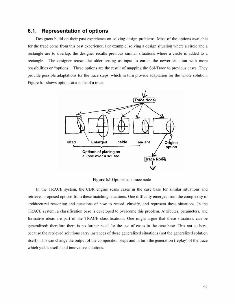
65
6.1. Representation of options Designers build on their past experience on solving design problems. Most of the options available
for the trace come from this past experience. For example, solving a design situation where a circle and a
rectangle are to overlap, the designer recalls previous similar situations where a circle is added to a
rectangle. The designer reuses the older setting as input to enrich the newer situation with more
possibilities or “options’. These options are the result of mapping the Sol-Trace to previous cases. They
provide possible adaptations for the trace steps, which in turn provide adaptation for the whole solution.
Figure 6.1 shows options at a node of a trace.
Figure 6.1 Options at a trace node
In the TRACE system, the CBR engine scans cases in the case base for similar situations and
retrieves proposed options from these matching situations. One difficulty emerges from the complexity of
architectural reasoning and questions of how to record, classify, and represent these situations. In the
TRACE system, a classification base is developed to overcome this problem. Attributes, parameters, and
formative ideas are part of the TRACE classifications. One might argue that these situations can be
generalized; therefore there is no further need for the use of cases in the case base. This not so here,
because the retrieved solutions carry instances of these generalized situations (not the generalized solution
itself). This can change the output of the composition steps and in turn the generation (replay) of the trace
which yields useful and innovative solutions.
66
6.1.1. Types of options The TRACE system trace tree represents options as branches that can be added at each node of the
solution path. Several types of options may be used in the Sol-Trace. There are two main categories of
options based on the way they are developed and used: operational and descriptive options. Operational
options are related to the actual act of introducing or changing something in the composition such as
adding, scaling or shifting components. For example, in a shift operation, possible options are changes to
the parameters of the shift. Many shift situations can be retrieved and a selection process takes place
before deciding on which ones are desired and actually can be applied at that node of the trace.
The second options category is the category of descriptive options. These options capture a change in
the node state. These captured changes are then mapped to similar situations in order to retrieve possible
variations or options. Although these options are descriptive in that they capture or describe a situation,
many of them include operations or placement, which makes them also form-giving options when
included within the sequence of the trace. These descriptions are from the corpus of architectural
composition notations and relations. They are stored in the classification base of concepts such as
formative ideas classification. An example of a composition step of this category is adding a circle to a
rectangle at its corner. This concept of adding a circle to a rectangle is one of the classifying formative
ideas. Other variations can be retrieved as options for this adding operation, such as adding the circle to
the edge of the rectangle, or tangent to its side. So, capturing and describing the situation in this way at a
particular node can be used in the indexing and retrieval of other related options which, at the same time,
provide form-giving alternatives.
Options are usually retrieved at the time when the trace is being used. Some of these options can be
added to the trace when it is built to allow for preserving and revealing salient generative characteristics
of the composition. Options may have different sources; therefore, five types of options can be identified:
1. Options available when building the trace: these options are created when the trace was built.
This type is very important; these are the options that the designer found useful for
understanding, preserving and adapting the trace when the trace was created. There is no better
understanding of the trace than when it was created, and that is the chance to include these
genuine options. These options can be used in the interactive adaptation to retrieve other similar
options from the case base.
2. Options retrieved from other cases. This is the basic workhorse of the traces. This includes
options that are automatically retrieved by the system based on criteria. These criteria can be
selected or weights can be assigned by the designer, or it can be left to the system (STE) to
retrieve useful situations according to the desired criteria and detected situations. This type also
67
includes options that the designer found in other cases (designer-controlled search and retrieval
of options).
3. Options adapted from other options to fit form or functional requirements. These options are
adapted by the designer through changing parameters and other characteristics. The extent of
adaptation is limited to what allows the option to remain valid for replay back into the trace. This
is controlled through the handlers in the option and the trace at that point. The designer can
freeze the option, which may represent a useful design state, and export it to another CAD
system for further development. In this case, the option cannot be re-entered onto the trace.
4. Options that are created by the designer: In this case, the designer has the responsibility to make
sure that the option will run within the trace. Designer must fulfill any required handlers in order
for the option to be used in the trace.
5. Options that are retrieved based on adapted query. These options are different in the way they
are matched and retrieved. The designer adjusts the query to fit the current problem needs. In
other words, the designer overrides some parameters/attributes that are used in the mapping and
retrieval of other options from the case base. This overriding can also be done by the system
detecting discrepancies between the option and the requirements in the current problem. For
example, if an element is being added at a step, the area of that element can be adjusted before
issuing the query to match the new problem. These options can be referred to as forced query
options.
6.1.2. Matching and retrieval of options Options in cases are a source of wealth of generative operations that can be used in adapting design
solutions to new problems. The retrieval process starts with mapping between the trace compositional
steps and other traces with similar steps. A particular step can be selected by the designer or by the
system. Then, similar steps are retrieved. For example, in one step along the trace, a scale operation is
introduced. This operation will match to other scale operations on other traces. The found scale operations
are retrieved to the current step as possible options for the scale operation. However, only a subset of
these scale operations will be useful options. These are the ones that match the requirements of the current
design problem. The requirements are the criteria on which the retrieval and selection are based. These
are the attributes and the descriptive characteristics of the operation, the shape(s), and other aspects at the
compositional step.
Options will be added based on this matching and retrieval process. The designer can assign weights
to the retrieval criteria. Other types of options can be created such as edited options, as described earlier.
68
There is also forced matching, where the designer decides to explore and retrieve similar (or different)
options matching a forced set of requirements (as in type 5 of options mentioned above), or to a chosen
characteristic of a solution. All matching processes are based on the attributes and parameters.
6.1.3. Using handlers with options The selection and the retrieval of an operation to be included within the trace node as an option are
determined by a set of criteria. However, for an option to be incorporated in the replay process of the
trace, it must have the required ‘handlers’ that exist at that node. These handlers control the applicability
of an option to be included within the trace.
Different operations may share the same set of handlers or part of it. This is important when the
handlers work as the only criteria for mapping and retrieval. The result is a multi-operations options that
can help in design exploration. For example a repetition operation requires an axis for the repetition
besides other aspects. An operation such as shift might use the same axis and part of the other aspects.
6.2. Handlers
6.2.1. Definition of handlers Handlers are the main constructs that control the applicability of operations and options at each node
of the trace. They are key elements in compositional steps, without which the step cannot be completed.
Other functions of handlers include synchronizing these steps throughout the trace and participating in
indexing and retrieval of operations and options. Handlers are control objects; therefore, more handlers
imply more restrictions on the kind of options or operations to be used. There should be a balance
between using more handlers and restricting options from being retrieved and used; and using fewer and
allowing a larger number of possibly irrelevant cases to be retrieved. This balance is crucial, particularly
for the TRACE system where adaptation is highly dependent on the retrieved and used options (cases).
Also, too many handlers can result in a limited range of options to be retrieved which in turn limits the
value of the system in generating innovative solutions.
A wide variety of compositional steps requires a large set of handlers. Within these steps, there is a
set of essential handlers for each operation to work properly. Working through these supported
operations, a combined set of handlers is developed. When building a Sol-Trace the minimum subset of
handlers that the operations require is used. Through these handlers, the main features of the composition
can be preserved, at the same time; handlers should allow a degree of openness to apply new operations
that can yield innovative unpredictable solutions.
69
Handlers are presented to the designer in order for the designer to follow the generation process and
to choose, edit, or build options that match the handlers at the current step of the trace. Designers can use
these handlers to search for and retrieve applicable options or operations. They can also introduce
additional restricting handlers to refine their search.
6.2.2. Types of handlers Handlers form the connection or the communication between trace composition steps. They also
allow flexibility in executing the operations without an exact match between the previous operation and
the following one. Each compositional step requires specific handlers within the composition for the step
to be executed. Based on the types of compositional steps, there are two types of handlers:
• Handlers required for the transformation operations, such as the ADD operation. These
handlers describe the key elements required for successful placement. They represent
points, lines, and other elements used in describing relations in the placement process. For
instance, if an ADD step requires an alignment with a line, the line becomes one of the
handlers for that step. And if no lines were identified in the composition, that ADD option
may not be retrieved, selected, or executed. Also some handlers are shared between
operations.
• Handlers required in the description of a concept, such as formative idea. In this case the
shapes and other elements of this concept might become the handlers. For example placing
a circle over a rectangle requires a rectangle shape to be presented in the composition. The
rectangle itself becomes a handler for this formative idea.
Handlers are also used in the selection among operations that can be applied in a certain node. If the
retrieved (or created) option carries the same handlers then it can be used and replayed into the trace. The
main concept is not to be very detailed and most of the time results in no matching cases. Or to change the
composition only marginally, which may result in merely pasting the different operations without
weaving it into the design in a meaningful integrated way.
Handlers can be viewed as specific parameters that allow interchangeability between similar and
different operations on the trace. They are the controlling parameters for the mechanism of the
development of the trace. The following is a list of general handler categories:
Axes: such as reflection axis or repetition axis etc.
Points of interest: such as center for rotation, placement point etc.
Angles: such as angles of rotations or other angles such as site angle
70
Increments and numbers involved in the operations: such as grid steps, modules etc.
Fixed sides: in compositions and operations that require stretching or moving
Alignment lines: for example aligning the composition element to a site line
Grids and governing structures: such as squared or angled grids
Others: can be developed through the use of the system
6.2.3. Trace handlers Trace handlers are a special type of handler. These handlers run through the entire trace. They
resemble global variables in a computer program. These handlers can control the margins of comparisons,
the overlapping allowed, restrictions, or other important aspects that run throughout the trace.
Chapter six focuses on the generative adaptation process in traces. Generative adaptation in traces is
provided mainly through the options mechanism. Options are the alternative settings for a compositional
step along the trace. Through retrieving the appropriate options and running them within the trace, new
adapted solutions are generated. Representation of options, types of options, and their use in traces
comprises the first section of this chapter. The second section is devoted to handlers, which are
mechanisms for controlling and selection of options in trace steps. Concepts presented in chapters so far
are utilized in a CBR system, TRACE. The focus of next chapter is the TRACE system development
process.

71
7. TRACE system operations, diagrams, and engines
Besides retrieving cases, TRACE provides an effective mechanism for retrieving and reusing the
knowledge required for adapting cases through the use of the trace representation. To make this happen,
several representations, operations, and CBR processes are required. Among the main representations in
TRACE are: Sol-Traces and options. Solutions are generated using Sol-Traces. CBR is the core reasoning
in TRACE and is used on several levels including case retrieval, solution options matching, and
adaptation of solution steps. TRACE performs these tasks with the help of the support engines: TRACE
CBR engine (CBRT), Sol-Traces Engine (STE), and the Artificial Intelligence Coordinator (AIC). In this
chapter, these representations and engines, along with the CBR process in TRACE, are explained in more
detail.
The TRACE system is developed using an object oriented modeling approach. ‘Together/J’1 is the
environment used for the design of TRACE. Object diagrams from the TRACE design are also presented
in this chapter. TRACE is implemented in Java using the ‘JBuilder’2 environment.
7.1. TRACE system architecture TRACE has a simple architecture which results from its logical components and their functions. The
TRACE system has three basic engines; the Sol-Traces engine (STE), the case-based reasoning engine
(CBRT), and the artificial intelligence coordinator (AIC). STE is responsible for the Sol-Traces
functionality including interactions with the designer. CBRT is responsible for the functionality of the
case base and the reasoning involved in matching, retrieving, and storing cases. It is also responsible for
maintaining the case base. The AIC works as the provider for intelligence services required in resolving
conflicts or in communicating between the two other engines. Figure 7.1 shows a schematic of the
TRACE system architecture.
1 Together/J is a product from Object International Software Ltd. Version 2.2.2, a white-board edition, is used in
developing TRACE. Together is currently acquired by Borland , USA.
2 Jbuilder is a product from Borland, USA. The version used in implementing TRACE is the FoundationX.

72
Figure 7.1 TRACE system architecture
7.2. Sol-Trace Engine (STE) - Solution generation The traces are the core structures for generating solutions. The main process is to generate solutions
from the trace options. There are different types of solutions within the trace: The original solution, other
developed solutions, and temporary solutions for the current session. Each solution is a series of options
numbered according to their rank at each node. Each trace node has a table of the available options.
Generating a solution runs the selected option at each trace node until the sequence of the trace is
finished. The trace engine (STE) is responsible for this process.
This engine is responsible for verifying the compatibility of the option at the node with the
composition so far. This involves checking the settings, handlers, and relations accompanying the option
against the composition handlers or global constraints. In case of a conflict, the trace delegates the
problem to the Artificial Intelligence Coordinator (AIC) to make a decision or to modify the option to fit
within the trace.
The trace engine is also responsible for building a query to retrieve other options at a particular node.
This query is sent to the CBR engine for execution. The query is built using many aspects including the
designer’s choices, the node settings, and the global required characteristics. In many cases, the AIC can
resolve and refine the query before sending it to the CBRT engine. These options come from different
sources, such as the designer’s choices from abstracted and generalized situations or from cases in the
case base. The STE engine works at each node of the trace to bring other options or alternatives to the
state in a way that matches particular criteria or preferences related to the current problem and set by the
designer or the AIC.
After filling these options, the engine starts composing different solutions through a selection
processes. The options can be refined and many can be excluded from the node table. The process has two
different approaches; the automatic allocation of these options or the designer’s choices. The automatic
allocation is supervised by the AIC controller, which gives suggestions to alter the trace through these
options and generates new solutions. In the current TRACE prototype, only the designer’s selections are
73
supported. In general this process is called replay, and it can be done in many different ways, such as
exhaustively trying all available options or selectively running a set of them as indicated earlier.
The functions of the STE can be summarized as follows:
• Run the trace: Generate a solution that is encoded as a trace. In this process, the STE
verifies the compatibility of options and the proper sequence of composition steps. The STE
might use the AIC to resolve conflicts in options or their handlers in the composition steps
along the trace.
• Respond to designer interactions with the trace: This includes a designer selecting an
option to run, deleting or editing an option, or adding an option. The STE manages the
proper handling of these procedures and maintains the consistency of the trace.
• Add retrieved options: This is the main task that STE performs with communication with
the CBRT. The STE builds and issues a query based on the designer’s choices and other
aspects in the composition step. The STE might use the AIC to participate in formulating
this query whenever there are conflicts or intelligent tasks that the STE cannot handle.
• Store the retrieved options: The STE stores the retrieved options in a table and preserves
their rank. The rank reflects how these options were found in the case base and how closley
they match the criteria in the query.
• Make selections: The STE selects among options within the trace to satisfy the needs of the
designer or as instructed by the AIC.
7.3. CBR engine in TRACE (CBRT) CBR is at the core of the TRACE system. It is used in many ways and at different levels of the
system. The first is for the retrieval of cases from the case base. The second is for the retrieval of cases
based on traces or for the retrieval of traces. The third is for the retrieval of trace options. The CBR
engine is responsible for all CBR activities, including indexing, matching, and retrieval. It also provides
the appropriate case storage and allows the designer to add a new case to the case base.
The main functions of CBRT are:
• Manage and index cases, traces, and options: This includes building classifications to
index cases in the case base. The engine provides internal implementation of classifications
of cases, traces, and options. All aspects of classifications in TRACE are implemented in
CBRT.
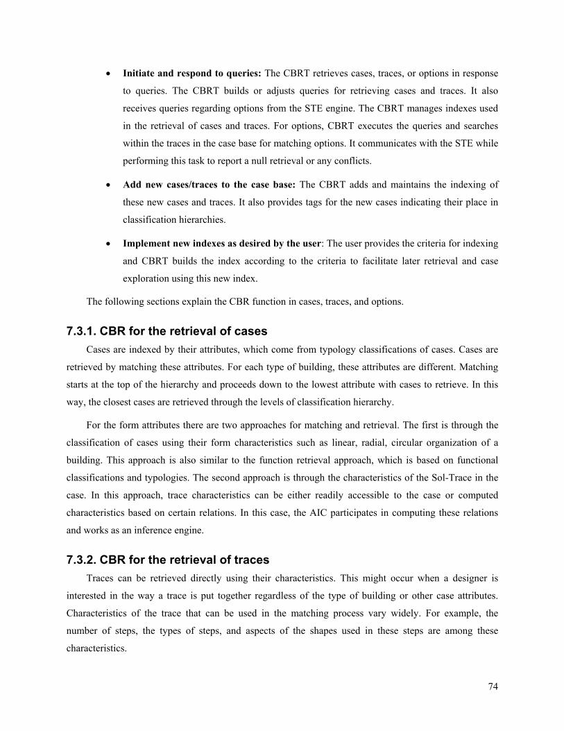
74
• Initiate and respond to queries: The CBRT retrieves cases, traces, or options in response
to queries. The CBRT builds or adjusts queries for retrieving cases and traces. It also
receives queries regarding options from the STE engine. The CBRT manages indexes used
in the retrieval of cases and traces. For options, CBRT executes the queries and searches
within the traces in the case base for matching options. It communicates with the STE while
performing this task to report a null retrieval or any conflicts.
• Add new cases/traces to the case base: The CBRT adds and maintains the indexing of
these new cases and traces. It also provides tags for the new cases indicating their place in
classification hierarchies.
• Implement new indexes as desired by the user: The user provides the criteria for indexing
and CBRT builds the index according to the criteria to facilitate later retrieval and case
exploration using this new index.
The following sections explain the CBR function in cases, traces, and options.
7.3.1. CBR for the retrieval of cases Cases are indexed by their attributes, which come from typology classifications of cases. Cases are
retrieved by matching these attributes. For each type of building, these attributes are different. Matching
starts at the top of the hierarchy and proceeds down to the lowest attribute with cases to retrieve. In this
way, the closest cases are retrieved through the levels of classification hierarchy.
For the form attributes there are two approaches for matching and retrieval. The first is through the
classification of cases using their form characteristics such as linear, radial, circular organization of a
building. This approach is also similar to the function retrieval approach, which is based on functional
classifications and typologies. The second approach is through the characteristics of the Sol-Trace in the
case. In this approach, trace characteristics can be either readily accessible to the case or computed
characteristics based on certain relations. In this case, the AIC participates in computing these relations
and works as an inference engine.
7.3.2. CBR for the retrieval of traces Traces can be retrieved directly using their characteristics. This might occur when a designer is
interested in the way a trace is put together regardless of the type of building or other case attributes.
Characteristics of the trace that can be used in the matching process vary widely. For example, the
number of steps, the types of steps, and aspects of the shapes used in these steps are among these
characteristics.
75
Although the interest here is in the trace (the form structure), building function and other functional
attributes can be used to narrow the search or, on the contrary, to diversify the traces by including traces
that would not have been retrieved under strictly one function. Queries using this tactic can yield diverse
results. In other words, in many situations there is a need to include matching attributes other than the
form characteristics of the trace in the matching query. The other tactic of leaving the query open to all
possible attributes can yield too many cases to be useful.
The retrieved traces are displayed to the designer to choose from. The designer can copy options
from trace to another or modify options on the trace. The designer can also use these traces to access more
information about their cases.
7.3.3. CBR for the retrieval of trace options Retrieval of options is one of the most important use of CBR technology in the TRACE system. It
covers almost all the phases of CBR, starting with indexing, matching, retrieval, and adaptation. The
retrieved options work both as adapted cases and as adaptation strategies.
Matching options starts with the preparation of a matching query. The matching query is constructed
using the choices of the designer from abstracted and generalized options for each particular type of
compositional step in the trace. Using these choices, options in other traces are matched and retrieved.
Options are matched using attributes, parameters, settings and handlers. The designer can assign weights
for these aspects or rank them according to their importance.
The retrieved options are stored in a table at each node. They are given a ranking number indicating
an evaluation of their matching. The table of options is used in building different solutions. The designer
can delete non-preferable options in the table. Also, the designer can change options ranking. Selections
from the table can be subject to other criteria either by the system or by the designer. Among these criteria
are the trace settings and handlers or other constraints imposed by the trace.
7.4. Artificial Intelligence Coordinator (AIC) The AIC is responsible for handling any intelligence related activity in retrieving and adapting cases,
Sol-Traces, and options. The AIC monitors the status of the form generation and the adaptation in the
trace. It takes control whenever there is a problem or undefined or frozen status. It is responsible for
resolving these problems and reporting the unsolved ones to the designer. It plays a role in the design
generation itself, through resolving conflicts and guiding the generation in the valid, possible, or
acceptable directions. It also decides whether to run one option at a time or several together, and whether
to seek help from the designer in this process or rely on the available system possibilities in achieving
desired solutions. In the retrieval process, the AIC decides whether to expand the matching process or not
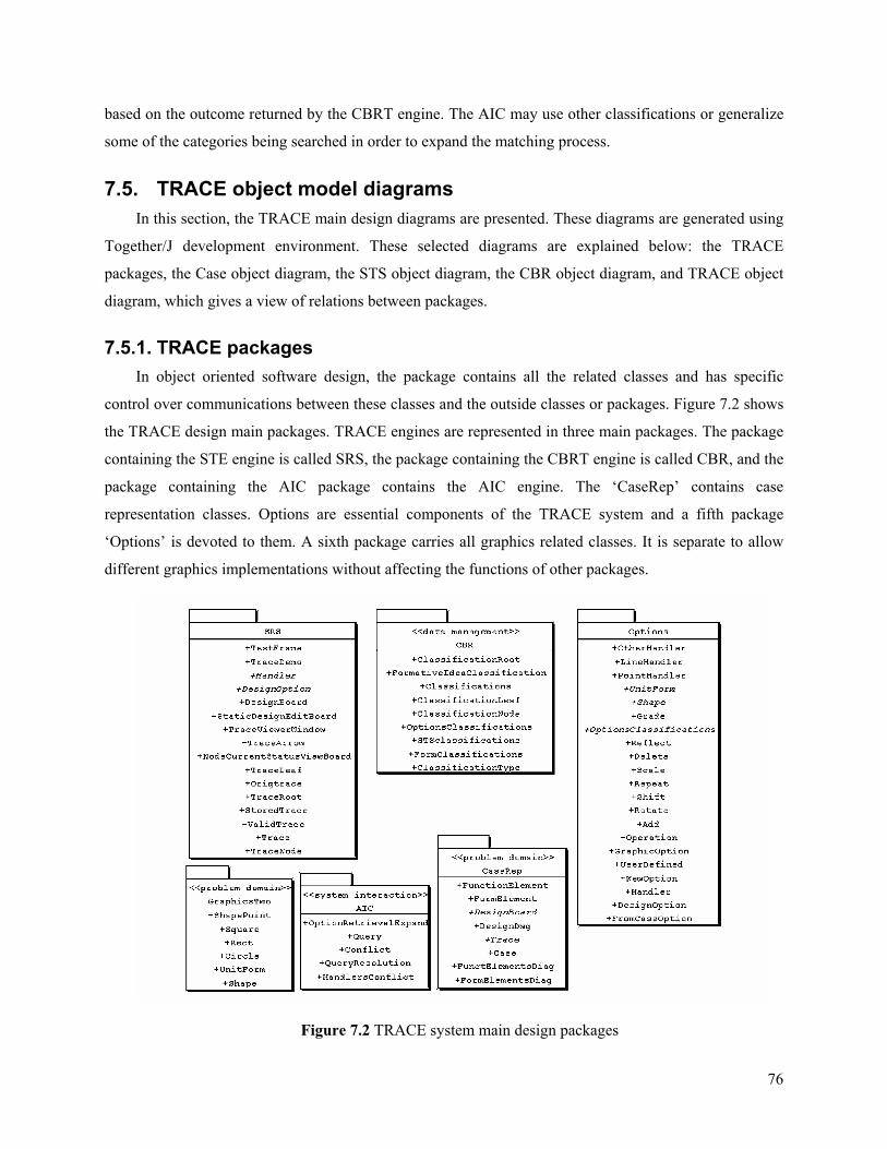
76
based on the outcome returned by the CBRT engine. The AIC may use other classifications or generalize
some of the categories being searched in order to expand the matching process.
7.5. TRACE object model diagrams In this section, the TRACE main design diagrams are presented. These diagrams are generated using
Together/J development environment. These selected diagrams are explained below: the TRACE
packages, the Case object diagram, the STS object diagram, the CBR object diagram, and TRACE object
diagram, which gives a view of relations between packages.
7.5.1. TRACE packages In object oriented software design, the package contains all the related classes and has specific
control over communications between these classes and the outside classes or packages. Figure 7.2 shows
the TRACE design main packages. TRACE engines are represented in three main packages. The package
containing the STE engine is called SRS, the package containing the CBRT engine is called CBR, and the
package containing the AIC package contains the AIC engine. The ‘CaseRep’ contains case
representation classes. Options are essential components of the TRACE system and a fifth package
‘Options’ is devoted to them. A sixth package carries all graphics related classes. It is separate to allow
different graphics implementations without affecting the functions of other packages.
Figure 7.2 TRACE system main design packages
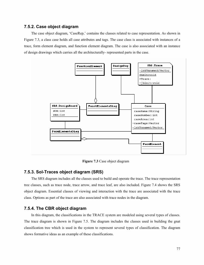
77
7.5.2. Case object diagram The case object diagram, ‘CaseRep,’ contains the classes related to case representation. As shown in
Figure 7.3, a class case holds all case attributes and tags. The case class is associated with instances of a
trace, form element diagram, and function element diagram. The case is also associated with an instance
of design drawings which carries all the architecturally- represented parts in the case.
Figure 7.3 Case object diagram
7.5.3. Sol-Traces object diagram (SRS) The SRS diagram includes all the classes used to build and operate the trace. The trace representation
tree classes, such as trace node, trace arrow, and trace leaf, are also included. Figure 7.4 shows the SRS
object diagram. Essential classes of viewing and interaction with the trace are associated with the trace
class. Options as part of the trace are also associated with trace nodes in the diagram.
7.5.4. The CBR object diagram In this diagram, the classifications in the TRACE system are modeled using several types of classes.
The trace diagram is shown in Figure 7.5. The diagram includes the classes used in building the gnat
classification tree which is used in the system to represent several types of classification. The diagram
shows formative ideas as an example of these classifications.
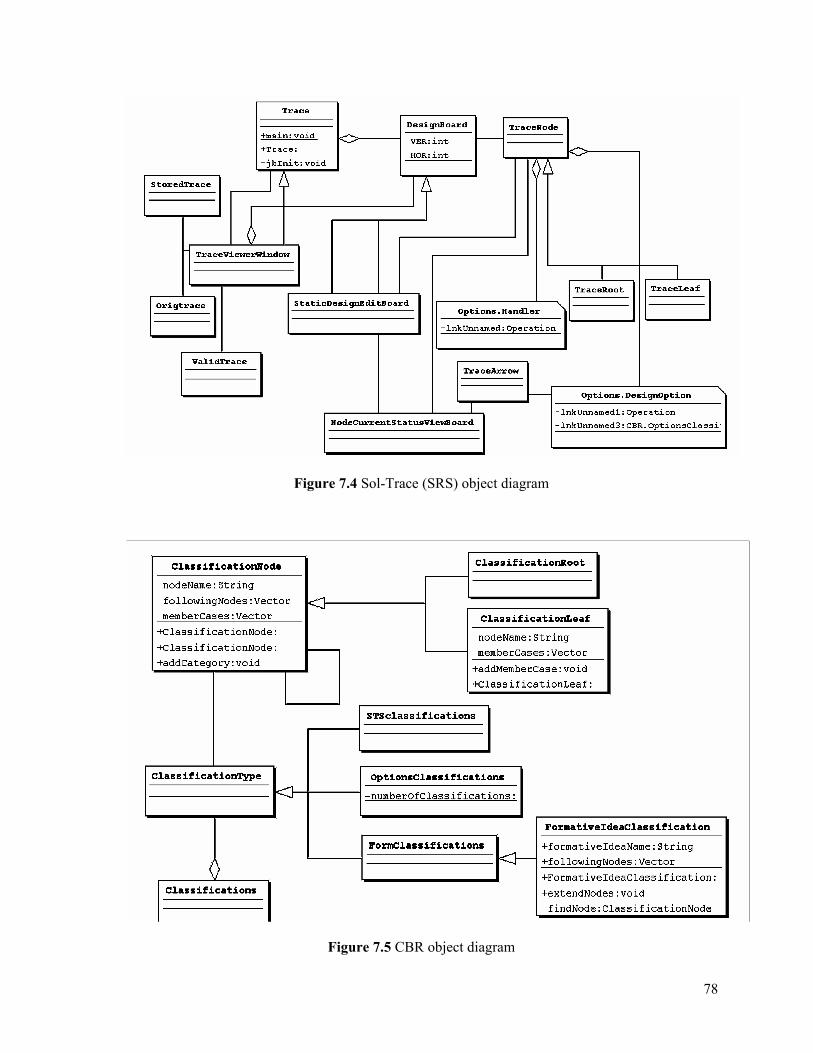
78
Figure 7.4 Sol-Trace (SRS) object diagram
Figure 7.5 CBR object diagram
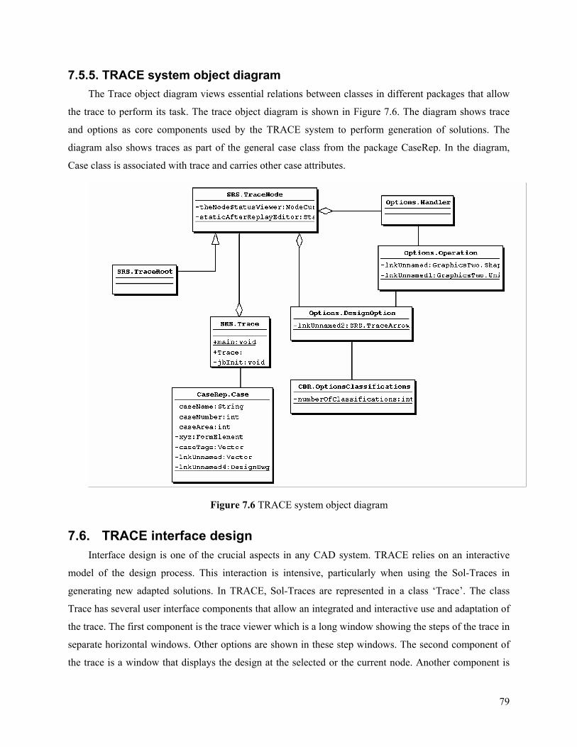
79
7.5.5. TRACE system object diagram The Trace object diagram views essential relations between classes in different packages that allow
the trace to perform its task. The trace object diagram is shown in Figure 7.6. The diagram shows trace
and options as core components used by the TRACE system to perform generation of solutions. The
diagram also shows traces as part of the general case class from the package CaseRep. In the diagram,
Case class is associated with trace and carries other case attributes.
Figure 7.6 TRACE system object diagram
7.6. TRACE interface design Interface design is one of the crucial aspects in any CAD system. TRACE relies on an interactive
model of the design process. This interaction is intensive, particularly when using the Sol-Traces in
generating new adapted solutions. In TRACE, Sol-Traces are represented in a class ‘Trace’. The class
Trace has several user interface components that allow an integrated and interactive use and adaptation of
the trace. The first component is the trace viewer which is a long window showing the steps of the trace in
separate horizontal windows. Other options are shown in these step windows. The second component of
the trace is a window that displays the design at the selected or the current node. Another component is
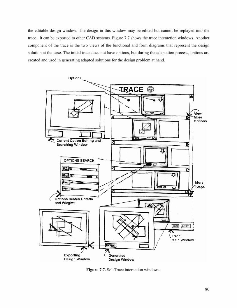
80
the editable design window. The design in this window may be edited but cannot be replayed into the
trace . It can be exported to other CAD systems. Figure 7.7 shows the trace interaction windows. Another
component of the trace is the two views of the functional and form diagrams that represent the design
solution at the case. The initial trace does not have options, but during the adaptation process, options are
created and used in generating adapted solutions for the design problem at hand.
Figure 7.7. Sol-Trace interaction windows
81
As the trace is constructed from a sequence of operations (or states), the trace is viewed in a long
window allowing to the designer to follow the evolution of the trace. This window represents the internal
tree data structure that holds the trace. Figure 7.7 shows that the trace window is divided horizontally with
horizontal sub-windows. Each sub-window shows a trace composition step until the complete
composition is reached. The Sol-Trace can be followed visually by the designer through this stack of
windows. The sub-windows represent a series of frames or viewers of the design state at each node. When
the trace is retrieved before adaptation, there is only one frame at each step. For example in an adding
step, the frame shows the added new shape. These single frames inside each sub-window represent the
current trace composition step. In the adaptation process, at each step, there are more options than the
original option provided by the trace. These options are viewed in frames within the sub-window. The
sub-window can show up to three frames of options and allows for scrolling horizontally to view more of
these frames. The original options of the trace are highlighted so that the designer can choose them again
if needed. The current trace options are indicated with arrows and could be aligned vertically if desired
for verification.
In the adaptation process, the designer can choose a node (a sub-window) along the trace and request
the system to find different options for that particular node. For example, for a repetition process, options
may be other similar repetitions from cases in the case base. These similar options are retrieved and
viewed in the frames. The designer browses these frames and chooses which option to be included in the
trace formulation. Then, the designer issues the command for replaying the trace and he/she evaluates the
result.
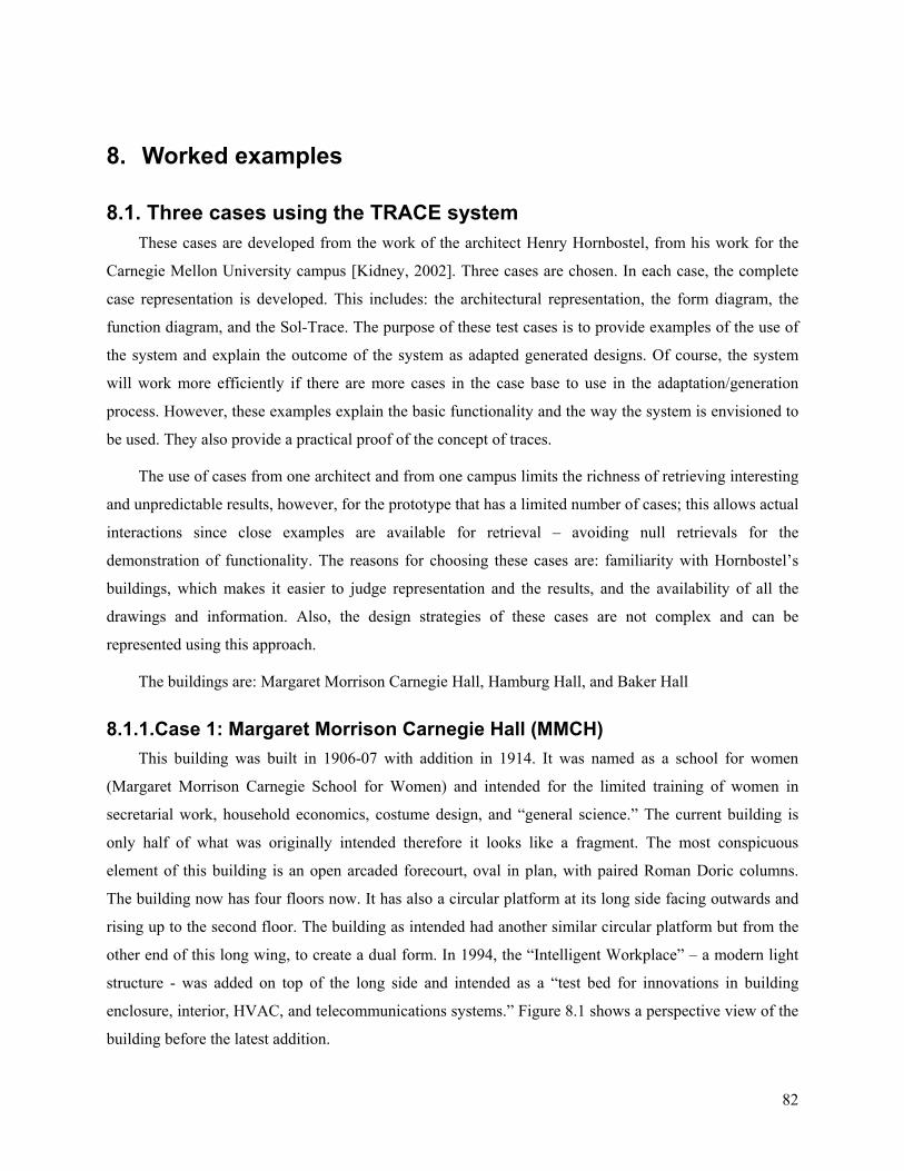
82
8. Worked examples
8.1. Three cases using the TRACE system These cases are developed from the work of the architect Henry Hornbostel, from his work for the
Carnegie Mellon University campus [Kidney, 2002]. Three cases are chosen. In each case, the complete
case representation is developed. This includes: the architectural representation, the form diagram, the
function diagram, and the Sol-Trace. The purpose of these test cases is to provide examples of the use of
the system and explain the outcome of the system as adapted generated designs. Of course, the system
will work more efficiently if there are more cases in the case base to use in the adaptation/generation
process. However, these examples explain the basic functionality and the way the system is envisioned to
be used. They also provide a practical proof of the concept of traces.
The use of cases from one architect and from one campus limits the richness of retrieving interesting
and unpredictable results, however, for the prototype that has a limited number of cases; this allows actual
interactions since close examples are available for retrieval – avoiding null retrievals for the
demonstration of functionality. The reasons for choosing these cases are: familiarity with Hornbostel’s
buildings, which makes it easier to judge representation and the results, and the availability of all the
drawings and information. Also, the design strategies of these cases are not complex and can be
represented using this approach.
The buildings are: Margaret Morrison Carnegie Hall, Hamburg Hall, and Baker Hall
8.1.1.Case 1: Margaret Morrison Carnegie Hall (MMCH) This building was built in 1906-07 with addition in 1914. It was named as a school for women
(Margaret Morrison Carnegie School for Women) and intended for the limited training of women in
secretarial work, household economics, costume design, and “general science.” The current building is
only half of what was originally intended therefore it looks like a fragment. The most conspicuous
element of this building is an open arcaded forecourt, oval in plan, with paired Roman Doric columns.
The building now has four floors now. It has also a circular platform at its long side facing outwards and
rising up to the second floor. The building as intended had another similar circular platform but from the
other end of this long wing, to create a dual form. In 1994, the “Intelligent Workplace” – a modern light
structure - was added on top of the long side and intended as a “test bed for innovations in building
enclosure, interior, HVAC, and telecommunications systems.” Figure 8.1 shows a perspective view of the
building before the latest addition.

83
Figure 8.1 Perspective view of the MMCH building, before the addition at the long wing
Building attributes:
- Type: educational: College
- Floors: 4 floors – 3 basements
- Construction: Brick – steel frame
- Architect: Henry Hornbostel
- Date: 1907 – 1914
- Form: L shape, oval entrance, circle plus rectangle
The architectural representation: Figure 8.1 a perspective view of the building; Figure 8.2 the first
floor plan.
Figure 8.2 First floor plan of MMCH bldg

84
Functional diagram (FND): Figure 8.3 provides example of a functional diagram abstracted from the
first floor. The first floor plan is used in developing this diagram. Spaces are represented with circular or
elliptical shapes with equal areas. The diagram preserves the topology relation between the functional
elements. The diagram shows both use and circulation spaces.
Figure 8.3 The function diagram of the MMCH bldg
Form diagram (FMD): Figure 8.4 provides an example of the form diagram. The form diagram is an
abstraction of the compositional concept manifested in the case. Form elements in the form diagram are
assembled with wide variety of relations. The elements have same areas and can share other attributes
with the function diagram.
Figure 8.4 The form diagram of MMCH building
Sol-Trace: Figure 8.5 shows the Sol-Trace abstraction for MMCH building. There are seven
compositional steps:
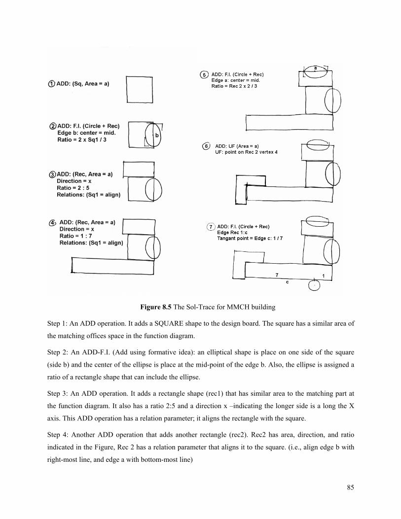
85
Figure 8.5 The Sol-Trace for MMCH building
Step 1: An ADD operation. It adds a SQUARE shape to the design board. The square has a similar area of
the matching offices space in the function diagram.
Step 2: An ADD-F.I. (Add using formative idea): an elliptical shape is place on one side of the square
(side b) and the center of the ellipse is place at the mid-point of the edge b. Also, the ellipse is assigned a
ratio of a rectangle shape that can include the ellipse.
Step 3: An ADD operation. It adds a rectangle shape (rec1) that has similar area to the matching part at
the function diagram. It also has a ratio 2:5 and a direction x –indicating the longer side is a long the X
axis. This ADD operation has a relation parameter; it aligns the rectangle with the square.
Step 4: Another ADD operation that adds another rectangle (rec2). Rec2 has area, direction, and ratio
indicated in the Figure, Rec 2 has a relation parameter that aligns it to the square. (i.e., align edge b with
right-most line, and edge a with bottom-most line)
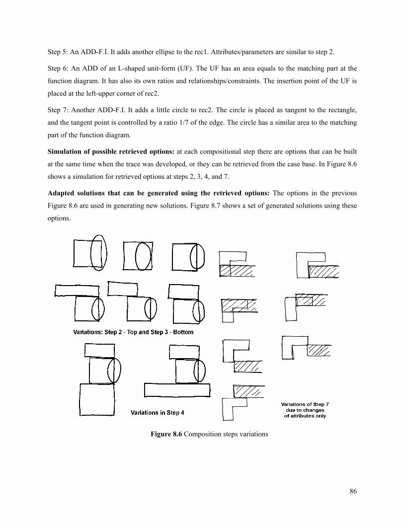
86
Step 5: An ADD-F.I. It adds another ellipse to the rec1. Attributes/parameters are similar to step 2.
Step 6: An ADD of an L-shaped unit-form (UF). The UF has an area equals to the matching part at the
function diagram. It has also its own ratios and relationships/constraints. The insertion point of the UF is
placed at the left-upper corner of rec2.
Step 7: Another ADD-F.I. It adds a little circle to rec2. The circle is placed as tangent to the rectangle,
and the tangent point is controlled by a ratio 1/7 of the edge. The circle has a similar area to the matching
part of the function diagram.
Simulation of possible retrieved options: at each compositional step there are options that can be built
at the same time when the trace was developed, or they can be retrieved from the case base. In Figure 8.6
shows a simulation for retrieved options at steps 2, 3, 4, and 7.
Adapted solutions that can be generated using the retrieved options: The options in the previous
Figure 8.6 are used in generating new solutions. Figure 8.7 shows a set of generated solutions using these
options.
Figure 8.6 Composition steps variations
87
Figure 8.7 Generated alternative solutions
8.1.2. Case 2: Hamburg Hall (HBH) -Hamburg Hall is originally designed as a governmental building for U.S. Bureau of Mines in 1915 -
1917 and designed by Henry Hornbostel. It is simple symmetrical building with three floors and a
distinguished arched entrance. It has a semi-circular lecture hall extended behind the building, on axis
with its main entrance.
Building attributes:
- Type: educational: College
- Floors: 3 floors – 1 basements
- Construction: Brick – steel frame
- Architect: Henry Hornbostel
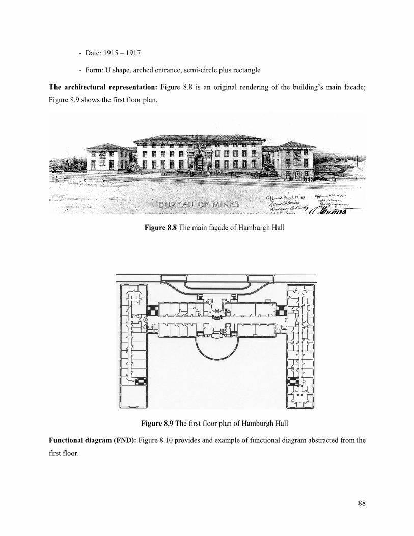
88
- Date: 1915 – 1917
- Form: U shape, arched entrance, semi-circle plus rectangle
The architectural representation: Figure 8.8 is an original rendering of the building’s main facade;
Figure 8.9 shows the first floor plan.
Figure 8.8 The main façade of Hamburgh Hall
Figure 8.9 The first floor plan of Hamburgh Hall
Functional diagram (FND): Figure 8.10 provides and example of functional diagram abstracted from the
first floor.
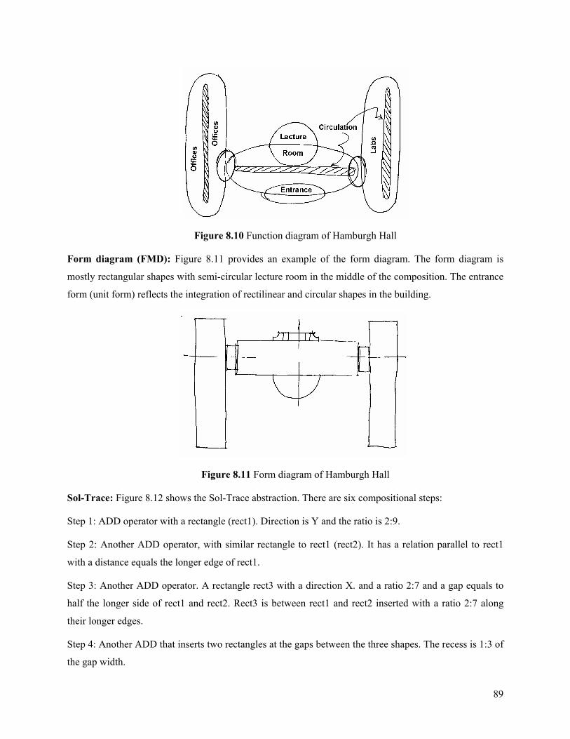
89
Figure 8.10 Function diagram of Hamburgh Hall
Form diagram (FMD): Figure 8.11 provides an example of the form diagram. The form diagram is
mostly rectangular shapes with semi-circular lecture room in the middle of the composition. The entrance
form (unit form) reflects the integration of rectilinear and circular shapes in the building.
Figure 8.11 Form diagram of Hamburgh Hall
Sol-Trace: Figure 8.12 shows the Sol-Trace abstraction. There are six compositional steps:
Step 1: ADD operator with a rectangle (rect1). Direction is Y and the ratio is 2:9.
Step 2: Another ADD operator, with similar rectangle to rect1 (rect2). It has a relation parallel to rect1
with a distance equals the longer edge of rect1.
Step 3: Another ADD operator. A rectangle rect3 with a direction X. and a ratio 2:7 and a gap equals to
half the longer side of rect1 and rect2. Rect3 is between rect1 and rect2 inserted with a ratio 2:7 along
their longer edges.
Step 4: Another ADD that inserts two rectangles at the gaps between the three shapes. The recess is 1:3 of
the gap width.
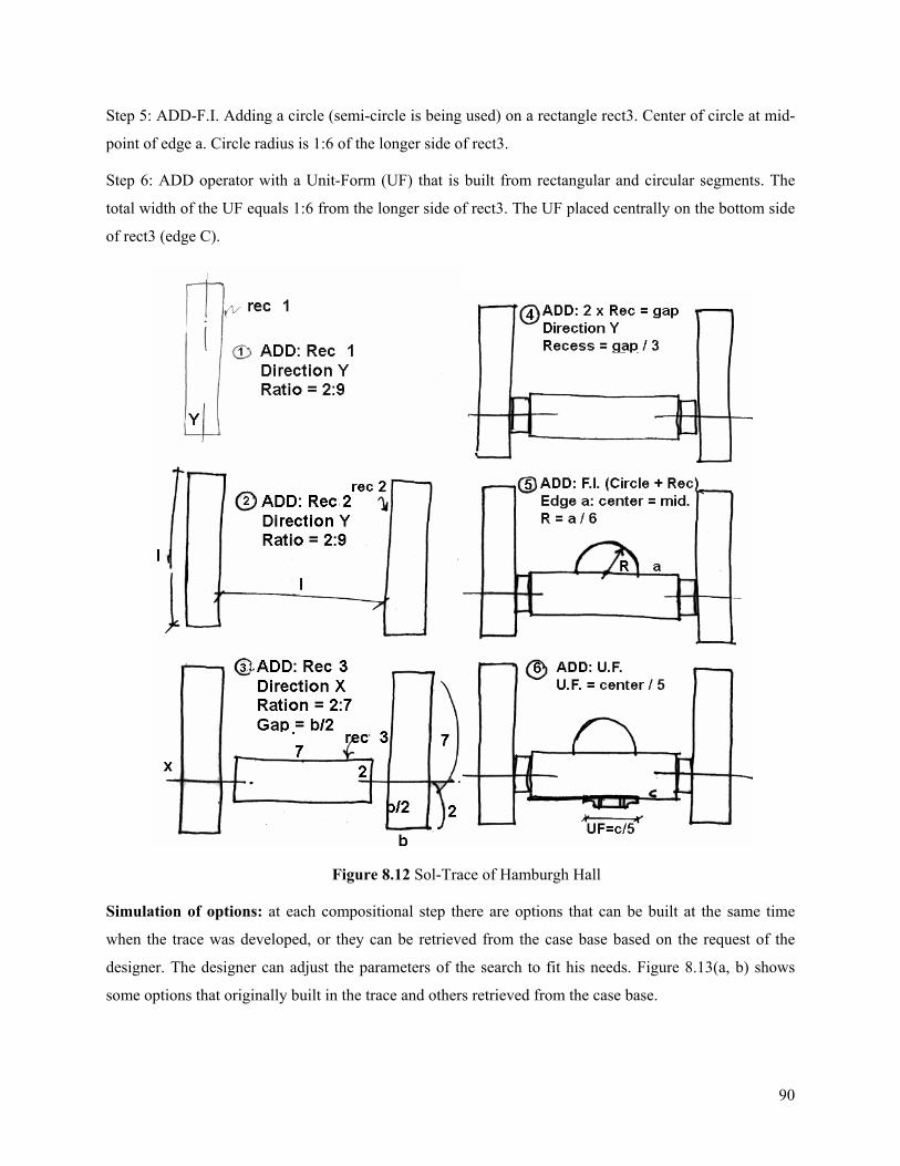
90
Step 5: ADD-F.I. Adding a circle (semi-circle is being used) on a rectangle rect3. Center of circle at mid-
point of edge a. Circle radius is 1:6 of the longer side of rect3.
Step 6: ADD operator with a Unit-Form (UF) that is built from rectangular and circular segments. The
total width of the UF equals 1:6 from the longer side of rect3. The UF placed centrally on the bottom side
of rect3 (edge C).
Figure 8.12 Sol-Trace of Hamburgh Hall
Simulation of options: at each compositional step there are options that can be built at the same time
when the trace was developed, or they can be retrieved from the case base based on the request of the
designer. The designer can adjust the parameters of the search to fit his needs. Figure 8.13(a, b) shows
some options that originally built in the trace and others retrieved from the case base.
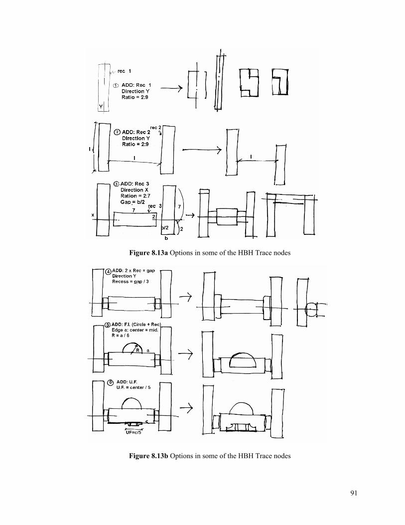
91
Figure 8.13a Options in some of the HBH Trace nodes
Figure 8.13b Options in some of the HBH Trace nodes
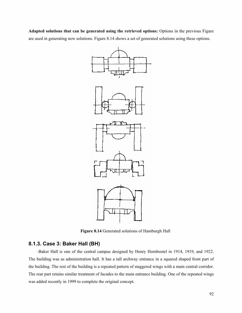
92
Adapted solutions that can be generated using the retrieved options: Options in the previous Figure
are used in generating new solutions. Figure 8.14 shows a set of generated solutions using these options.
Figure 8.14 Generated solutions of Hamburgh Hall
8.1.3. Case 3: Baker Hall (BH) -Baker Hall is one of the central campus designed by Henry Hornbostel in 1914, 1919, and 1922.
The building was as administration hall. It has a tall archway entrance in a squared shaped front part of
the building. The rest of the building is a repeated pattern of staggered wings with a main central corridor.
The rear part retains similar treatment of facades to the main entrance building. One of the repeated wings
was added recently in 1999 to complete the original concept.
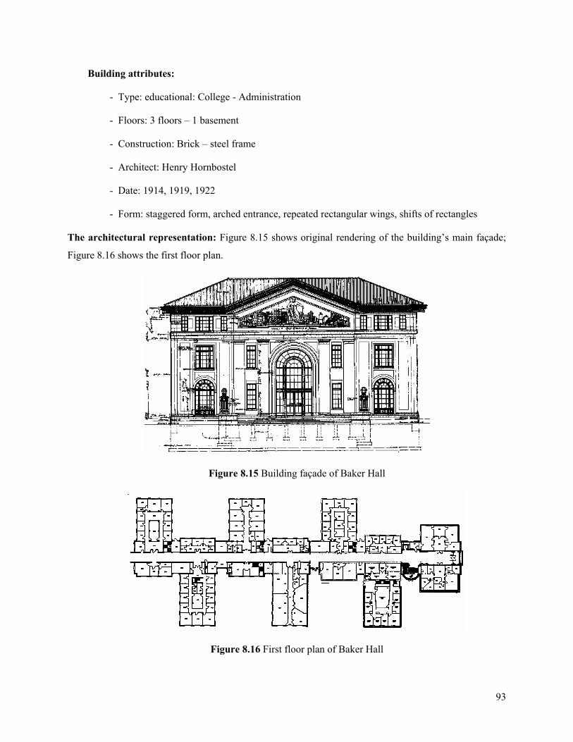
93
Building attributes:
- Type: educational: College - Administration
- Floors: 3 floors – 1 basement
- Construction: Brick – steel frame
- Architect: Henry Hornbostel
- Date: 1914, 1919, 1922
- Form: staggered form, arched entrance, repeated rectangular wings, shifts of rectangles
The architectural representation: Figure 8.15 shows original rendering of the building’s main façade;
Figure 8.16 shows the first floor plan.
Figure 8.15 Building façade of Baker Hall
Figure 8.16 First floor plan of Baker Hall
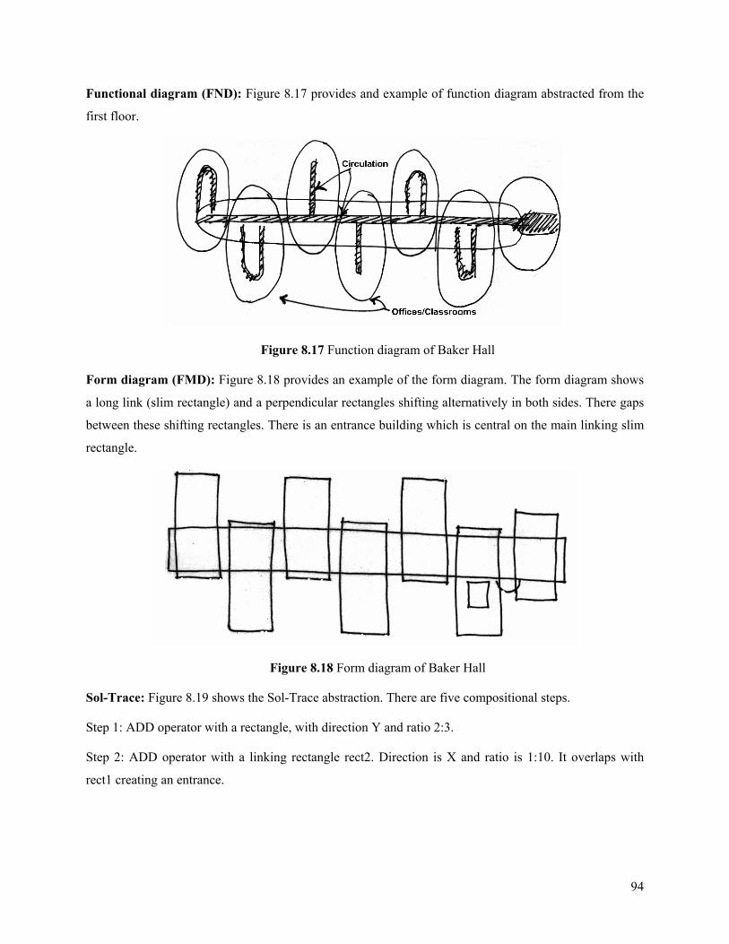
94
Functional diagram (FND): Figure 8.17 provides and example of function diagram abstracted from the
first floor.
Figure 8.17 Function diagram of Baker Hall
Form diagram (FMD): Figure 8.18 provides an example of the form diagram. The form diagram shows
a long link (slim rectangle) and a perpendicular rectangles shifting alternatively in both sides. There gaps
between these shifting rectangles. There is an entrance building which is central on the main linking slim
rectangle.
Figure 8.18 Form diagram of Baker Hall
Sol-Trace: Figure 8.19 shows the Sol-Trace abstraction. There are five compositional steps.
Step 1: ADD operator with a rectangle, with direction Y and ratio 2:3.
Step 2: ADD operator with a linking rectangle rect2. Direction is X and ratio is 1:10. It overlaps with
rect1 creating an entrance.
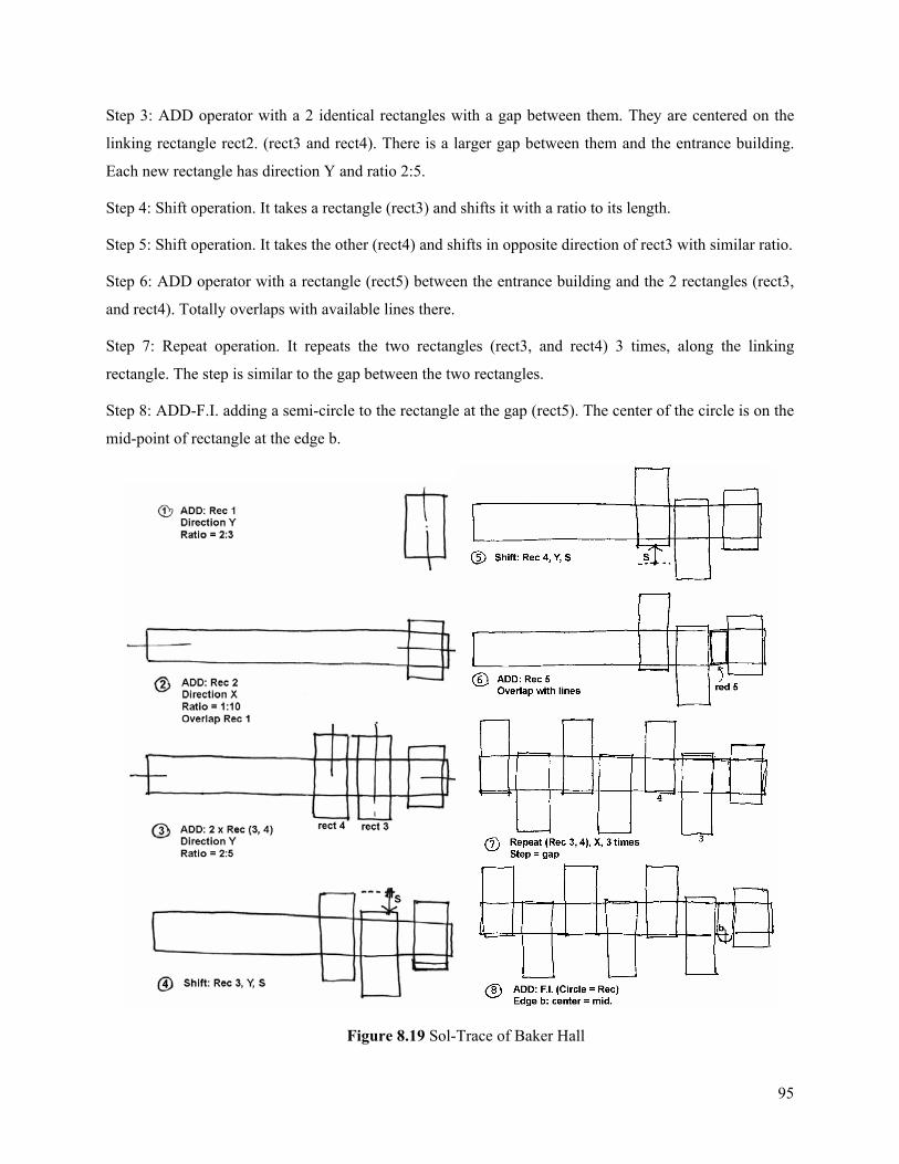
95
Step 3: ADD operator with a 2 identical rectangles with a gap between them. They are centered on the
linking rectangle rect2. (rect3 and rect4). There is a larger gap between them and the entrance building.
Each new rectangle has direction Y and ratio 2:5.
Step 4: Shift operation. It takes a rectangle (rect3) and shifts it with a ratio to its length.
Step 5: Shift operation. It takes the other (rect4) and shifts in opposite direction of rect3 with similar ratio.
Step 6: ADD operator with a rectangle (rect5) between the entrance building and the 2 rectangles (rect3,
and rect4). Totally overlaps with available lines there.
Step 7: Repeat operation. It repeats the two rectangles (rect3, and rect4) 3 times, along the linking
rectangle. The step is similar to the gap between the two rectangles.
Step 8: ADD-F.I. adding a semi-circle to the rectangle at the gap (rect5). The center of the circle is on the
mid-point of rectangle at the edge b.
Figure 8.19 Sol-Trace of Baker Hall
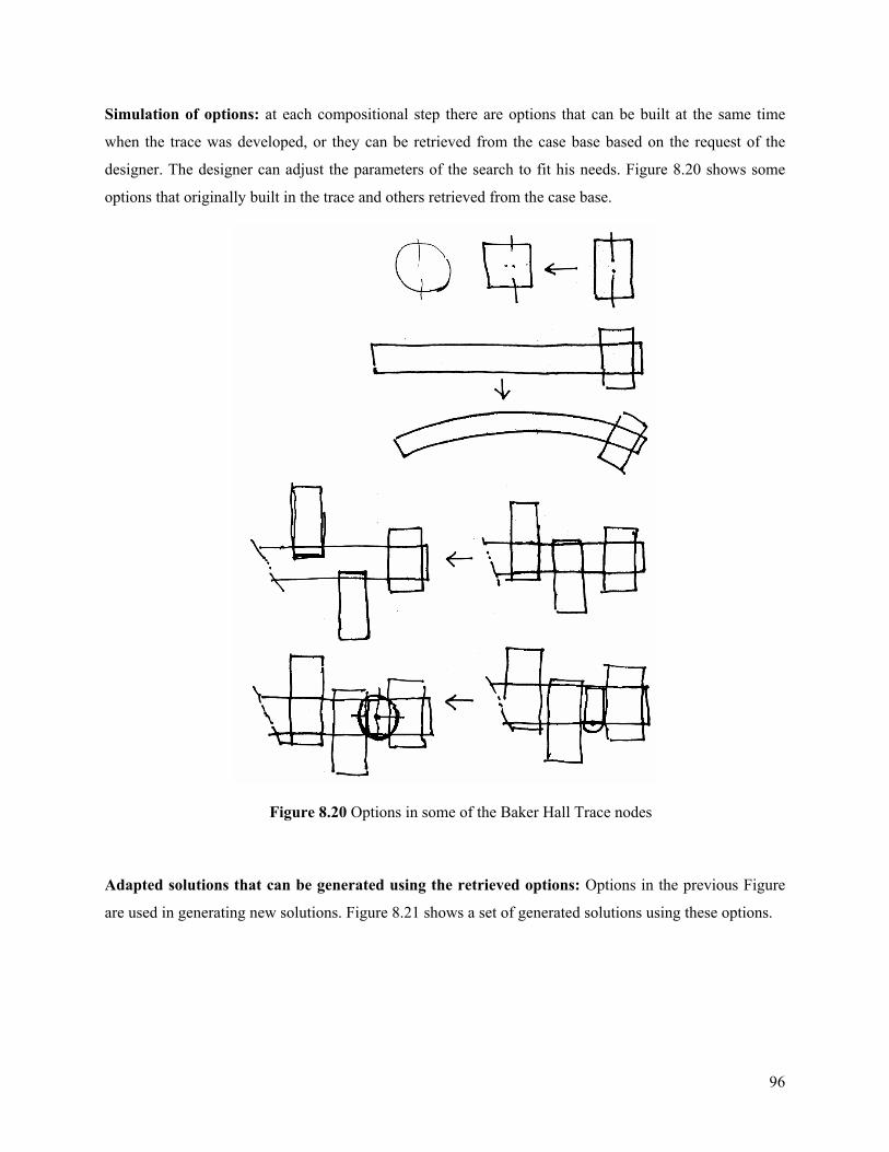
96
Simulation of options: at each compositional step there are options that can be built at the same time
when the trace was developed, or they can be retrieved from the case base based on the request of the
designer. The designer can adjust the parameters of the search to fit his needs. Figure 8.20 shows some
options that originally built in the trace and others retrieved from the case base.
Figure 8.20 Options in some of the Baker Hall Trace nodes
Adapted solutions that can be generated using the retrieved options: Options in the previous Figure
are used in generating new solutions. Figure 8.21 shows a set of generated solutions using these options.
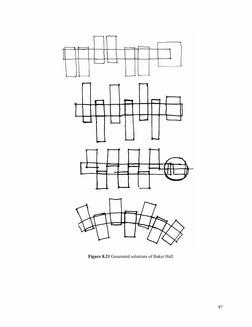
97
Figure 8.21 Generated solutions of Baker Hall
98
8.2. Observations Explain results of the cases that run through the system, as planned or manually run and as
computationally generated.
• It is important to analyze the form thoroughly and not to oversee any details or little aspect.
This should be done before embarking on abstracting the case into form diagram and trace.
• Main features of the composition should be emphasized. There might be required options to
be included that strengthen these features.
• It is very important to make connections between elements, particularly between their main
constructs such as axis, line, and point. These connections are stored as relations in the
composition steps.
• Sol-Traces abstraction needs a learning curve. Building several traces is required before
easy and effective development of traces is expected.
• Form and function diagrams can be used to input the required characteristics that can be
used in the search and retrieval (adaptation). These characteristics are entered by the
designer in order to adapt the trace.
• Adaptations can also be introduced at each composition step before issuing a matching
request. This is mostly done directly by the designer, but in later developments, the system
can automatically search for discrepancies in each step and adjust the matching request
accordingly.
• Sol-Trace abstraction is very effective when shared situations between cases are
maintained. In other words, the use situations can be generalized and shared between
different traces and different types of composition steps. This includes shapes, unit forms,
relations, and others.
• Ratio or proportions is among the feature in the composition when building the traces. In
many cases, proportions are the only dominant feature.
Suggested recipe for abstracting the traces:
1. Start with identifying the general or the main features of the composition
2. Look for options or variations of these features (can be included in the trace). This will help in
elucidating these features.
99
3. Capture or find the strategies of the composition i.e. main operations, transformations etc.
4. Identify the handlers of these elements/features/operations/transformations
5. Connect the identified handlers to the other elements/operations etc.
6. Sketch the composition steps without much details at this time
7. At each step identify the strategy or the operations clearly with possible handlers/parameters
affecting it.
8. Find if there is compositional line or point used through out the composition, or compositional
element (i.e. shape)
9. Sketch the composition steps again with the newly identified aspects
10. Learn the ratios or proportions in the whole composition and within each step. Find connections.
11. Sketch the steps with the proportions
12. Add the other options in each step
13. Make the steps clear with all the required details (parameters/ratios/handlers etc.)
In the presented examples, we are not so concerned to generate the exact form in the case using the
trace; the goal is to develop a construct that can be used in generating new designs. The use of virtual
shapes in the trace can help in many cases, along with other techniques that can alleviate the difficulties
encountered in representing the form using traces. Developing traces within cases required a brief
learning process.
100
9. Conclusions
The goal of this thesis is to support design composition in architecture. In this chapter, we discuss the
main contribution of this research. Future research directions that have emerged through the development
of this thesis will also be presented in this chapter
9.1. Contributions This thesis has contributed at the conceptual level to the field of computational support for early
phases of the design process, particularly design composition. The key idea of this thesis is the use of
design composition processes represented by work such as Clark and Pause, 1996]. Architects learn these
methods early in their studies, and the vocabulary, representations, and processes become familiar. This
thesis creates a computational representation and process for preliminary design that leverages both the
familiarity of this design composition method and its suitability for generative case based reasoning.
The thesis established a new approach for representing and solving design problems computationally
in the conceptual design phase. Based on this approach, this thesis has resulted in two main contributions:
the first is the development of a representation language for design composition and a design process
model using this language. The second is the methodology for generative adaptations in CBR in the
design domain.
9.1.1. The new conceptual approach for supporting design composition This thesis contributes to computational support for the early stages of design by providing a
framework that connects the way designers think with computational reasoning processes. The thesis
presents a language of visual processes, which is codified by designers in their practice and translates this
language into a computationally tractable representation. This framework of borrowing from one domain
to another is one of the important theoretical contributions of this thesis. This framework is used to
provide support for form composition in particular as a dominating process in the early phases of
architectural design.
9.1.2. The representation language for design composition The thesis presents a language for representing design that is computationally tractable. The
language abstracts the design composition into simple geometric forms and transformations can be
assembled using several conceptual schemes or strategies. The language represents the composition as
sequence of steps; each step introduces a change to the design form. Sol-Traces are constructs built from a

101
sequence of these steps. This sequential approach makes it easier to apply computation to design. Sol-
Traces allow computational support for a process that has been computationally inaccessible. This
language is open and capable of accommodating other strategies for design composition. This
contribution will provide new approaches for augmenting computation in the field of design.
9.1.3. Design process model at the early phases Based on the representational language and the concept of Sol-Traces, a new design process model is
presented. This design process model takes advantage of human designers’ superior ability to predict,
evaluate, judge, and select. The representation makes computation tractable by breaking down the process
into steps. The design process model relies on the interaction between the designer and the computer in
adapting these steps and regenerating solutions using Sol-Traces. The thesis provides examples for these
compositional steps and Sol-Traces. This design process model can be utilized by other CAD systems,
and it can facilitate computational support for design problems other than form composition.
9.1.4. Generative adaptation in CBR in design In using CBR in design, adaptation is one of the most difficult tasks that limits the benefits of the
CBR approach. The thesis provides a methodology for adaptation of design using derivational analogy.
The methodology is based on analogy to the techniques or processes used in developing the solution
rather than analogy to the solution itself. The generative adaptation, used in this thesis, provides logical
and acceptable strategies for reusing previous cases in architectural design composition. Adaptation is
achievable through adjusting the steps of Sol-Traces. The strategy relies on the contribution of these steps
in adjusting the overall solution. These steps are mapped against the similar stored steps. This mapping of
solution parts that are assembled is key in simplifying the adaptation process and the generative
mechanism. This approach of simplified generative adaptations adds to the methods and approaches used
to alleviate the burden of the adaptation process and, in turn, makes the adaptation process achievable.
9.2. Future research Important issues that emerged for future research can be summarized as follows:
1. Automatic generation of cases. This can be achieved in the traces by allowing the variation
(options) to be utilized in generating new cases and populating the case base. The generated
cases will be useful even though they are not abstracted from actual buildings. When designers
develop a form, they usually explore many directions that are worth recording. The options that
are created when the trace is built are helpful in this regard.
102
2. Approaches for intelligent retrieval. Intelligent retrieval to achieve better fit and interesting
solutions can be such as:
• Expansion of the search for cases options in order to match certain criteria. This expansion
can be achieved through several approaches. One approach is by providing selectable
categories in the query and a system to add to or expand the members of these categories.
The other approach is to tie the options with a system of classifications that allows several
paths for the expansion. For example, it can expand to include one level up, a neighboring
category, the root category, or accessing another classification hierarchy.
• Utilization of intelligent classifications. Classifications can direct the retrieval by
communicating with other selected classifications
• Selections between classifications such as the intersection or union of classifications.
3. Adding new strategies. New strategies may come from the way designs are generated such as
extrusion of a form, algorithmic forms, and evolutionary generation of forms.
4. Future research enhancements of the TRACE system:
• Apply the TRACE system to multi-story compositions. This can address the problem of
compatibility between floor plans and assure synchronization of the form composition.
• Apply the TRACE system for façade compositions and other 2D-form compositions in
building design such as interior design.
• Add functional-based options to the traces in order to allow alternative solution
compositions based on the function of these components. This strategy can be tested in the
TRACE system.
• Create 3D representation of forms. TRACE deals only with 2D forms and their
compositions. Support of 3D forms can be very beneficial for design composition, even
though it might be complex and require significant extensions to the theory.
• Allow users of the TRACE system to define and add their own adaptation operations and
the handlers to control them. An example of these customized operations could be extrusion
of a specific form or similar operations. However, handlers should be carefully developed to
assure the compatibility with other operations and handlers in the system. This
customization can allow the system to meet the needs of very specialized use.
103
• Expand the ideas and design concepts represented in the TRACE system. These design
concepts represent some of the core components of design composition. More design
concepts can be represented and added to the system. For instance, the axial reflection in the
system can be extended to allow for radial reflections. Further preferred enrichments are
envisioned to be recognized through the extensive utilization of the TRACE system in
generating design compositions.
• The automated detection of problems or discrepancies and automatically retrieving options
as a remedy for these discrepancies. This can be handled by the AIC in the TRACE system
and can provide automatic adaptation feature. Several alternatives can be generated using
the automatically retrieved options and the designer can participate in the final selection
between these alternatives.
• Implementing the functions of the Artificial intelligence coordinator (AIC) in the TRACE
system.
The previous points are intended for extensive future research. It is important to run usability studies
for the TRACE system before embarking on larger extensions. The current prototype of TRACE provides
a starting point for such studies. It is envisioned that TRACE system will evolve into an interesting
widely-used form design tool.
104
10. References
Aamodt, A. and Plaza, E. (1994). “Case-based reasoning: Foundational issues, methodological variations and system approaches.” AI communications, Vol. 7 No. 1, pp. 39-59.
Alexander, Christopher, (1977). A Pattern Language. Oxford University Press; New York.
Aygen, Zeno. (1999), A Hybrid model for case indexing and retrieval in building design, Ph.D. thesis, School of Architecture, Carnegie Mellon University, Pittsburgh, USA.
Baker, G.H. (1993), Design Strategies in Architecture: and approach to the analysis of form, Van Nostrand Reinhold, UK.
Bhatta, S., Goel, A., and Prabhakar, S. (1994) “Innovation in Analogical Design: A Model Based Approach,” Proc. Third Int’l Conf. AI in Design, Kluwer, pp. 57-74.
Bonnardel, N. and R. Megali (1998). “Analogies in Design Activities: A Study of the Evocation of Intra- and Interdomain Sources.” In K. Holyoak, D. Gentner, and B. Kokinov, Advances in Analogy Research: Integration of Theory and Data from the Cognitive, Computational, and Neural Sciences, Bulgaria, pp.336-343.
Borner, K. (1998), “CBR for design.” In Case-Based Reasoning Technology From Foundations to Applications, Lecture Notes in AI, Vol 1400, M. Lenz, B. Bartsch-Sporl, H.D. Burkhard, and S. Wess. eds, Springer-Verlag, New York.
Borner, K. (2002), Visual Interfaces to Digital Libraries, Springer-Verlag, Germany.
Bruton, D. (1997). “Grammars and Art.” In CAAD Futures 1997, Proceedings of the 7th International Conference on Computer Aided Architectural Design Futures, Munich, Germany, pp.71-82.
Carbonell, J.G. (1985). “Derivational Analogy: A Theory of Reconstructive Problem Solving and Expertise Acquisition.” Tech. Report, Computer Science Department, Carnegie-Mellon University, Pittsburgh, PA.
Casakin, H. and G. Goldschmidt (1999). “Expertise and the use of visual analogy: implications for design education.” Design Studies Vol. 20, No. 2, pp. 153-175.
Ching, F. (1979), Architecture: Form, Space and Order, Van Nostrand Reinhold, New York.
Chiu, M-L. and Shih, S-G. (1997). “Analogical Reasoning and Case Adaptation in Architectural Design: Computers vs. Human Designers.” In CAAD Futures 1997, Proceedings of the 7th International Conference on Computer Aided Architectural Design Futures, Munich, Germany, pp.787-800.
Clark, R.H. and M. Pause (1996). Precedents in Architecture, Second Edition, Van Nostrand Reinhold, New York.
Cross, N., Christiaans, H., and Dorst, K. eds., (1996), Analyzing Design Activity, J. Wiley & Sons.
105
Cunningham P., Finn D., and Slattery S. (1994). “Knowledge Engineering Requirements in Derivational Analogy.” In Topics in Case-Based Reasoning, Lecture Notes in Artificial Intelligence, S. Wess, K-D Althoff, M.M. Richter eds., Springer Verlag, pp234-245.
Domeshek, E. and Kolodner, J.L. (1992). “A case-based design aid for Architecture.” Artificial Intelligence in Design ’92, The Netherlands, pp. 497-516.
Domeshek, E.A., Zimring, C.M. and Kolodner, J.L. (1994). “Scaling up is hard to do: Experiences in preparing a case-based design aid prototype for field trial.” ASCE. American Society of Civil Engineers ’94. pp 430 - 437.
Downing, F. (2000). Remembrance and the Design of Place, Texas A&M Press, College Station TX, pp. 144.
Falkenhainer, B., Forbus, K.D., & Gentner, D. (1989). “The structure mapping engine: Algorithm and examples.” Artificial Intelligence, Vol 41, pp.1-63.
Finger, S. (1998). “Design Reuse and Design Research.” Design Reuse, Edited by S. Sivaloganathan and T.M.M. Shahin, Proceedings of Engineering Design Conference ’98, Professional Engineering Publishing Ltd., London, UK, pp.3-9.
Flemming, U. (1987). “More Than the Sum of Parts: The Grammar of Queen Anne House.” Environment and Planning B. Planning and Design, Vol 14,323-350.
Flemming, U., (1990). “Syntactic Structures in Architecture: Teaching Composition with Computer Assistance.” In Mitchell, W. and McCullough, M. eds. The Electronic Design Studio, M.I.T. Press, Cambridge, MA, pp.31-48.
Flemming, U. (1994). “Artificial Intelligence and Design: A Mid-Term Review.” In G. Carrara and Y.E. Kalay, eds., Knowledge-Based Computer-Aided Architectural Design, Elsevier, Netherlands, pp. 1-24.
Flemming, U. (1994a). “ Case-Based design in the SEED System.” in G. Carrara and Y. E. Kalay, eds., Knowledge-Based Computer-Aided Architectural Design, Elsevier, Netherlands, pp. 69-91.
Flemming, U. and Woodbury, R. (1995) Software environment to support early phases in building design: Overview. Journal of Architectural Engineering, Vol 4, No 1, pp 147-152.
Frazer, J. (1995). An Evolutionary Architecture, Architectural Association, London.
Gargus, J. (1994). Ideas of Order: A Formal Approach to Architecture, Kendall/Hunt Publishing Co., Iowa.
Gentner, D., (1983), “Structure mapping: a Theoretical Framework for Analogy.” Cognitive Science, Vol 7, No 2, pp. 155-170.
Gero, J.S. (1990). “Design prototypes: A knowledge representation schema for design.” AI Magazine, II Vol 4, pp. 26-36.
Goldschmidt, G. (1995). “Visual Displays for Design: Imagery, Analogy and Databases of Visual Images.” In Koutamanis A. ed., Visual Databases in Architecture, Avebury, pp.53-74.
106
Gross, M. D. and E. Y. Do (1994). “Using diagrams to access a case library of architectural designs.” In J.S. Gero & F. Sudweeks (eds.), Artificial Intelligence in Design ’94, Kluwer Academic Publisher, Netherlands, pp. 129 – 144.
Hampton, J. A (1998). “The Role of Similarity in How We Categorize The World.” In Holyoak, K., Gentner, D., and Kokinov, B., Advances in Analogy Research: Integration of Theory and Data from the Cognitive, Computational, and Neural Sciences, Bulgaria, pp.19-30.
Harrington, J.L. (2000), Object-Oriented Database Design Clearly Explained, Academic Press, CA.
Hovestadt, L. and Hovestadt, V. (1997). “Armilla 5- Supporting Design, Construction and Management of Complex Buildings.” In CAAD Futures 1997, Proceedings of the 7th International Conference on Computer Aided Architectural Design Futures, Munich, Germany, pp.135-150.
Jakimowicz, A., Barrallo, J., and Gueded, E.M. (1997). “Spatial Computer Abstraction: From Intuition to Genetic Algorithms.” In CAAD Futures 1997, Proceedings of the 7th International Conference on Computer Aided Architectural Design Futures, Munich, Germany, pp.917-926.
Jones, J.C., 1966. “Design Methods Reviewed.” In: S.A. Gregory (ed.), The Design Methods, London, Butterworth, and New York, Plenuum Press, pp. 295-309.
Juris, I.J. (1993). “Representation and Management Issues for Case-Based Reasoning Systems.” Department of Computer Science, University of Toronto, Ontario, Canada.
Kedar-Cabelli, S. (1988). “Analogy-From a Unified Perspective.” In Helman, D.H., ed., Analogical Reasoning: Perspective of Artificial Intelligence, Cognitive Science, and Philosophy, Kluwer Academic publishers, Netherlands, pp.65-103.
Kidney, W. C. (2002). Henry Hornbostel An Architect’s Master Touch, Pittsburgh History & Landmarks Foundation and Roberts Rinehart, Texas, USA.
Knight, T.W., (2001). “Shape grammars applications in architectural design, education, and practice.” Report for the NSF/MIT, Department of architecture, MIT, Cambridge, MA.
Kolarevic, B. (1997). “Regulating Lines and geometric Relations as a Framework for Exploring Shape, Dimension and Geometric Organization in Design.” In CAAD Futures 1997, Proceedings of the 7th International Conference on Computer Aided Architectural Design Futures, Munich, Germany, pp.163-170.
Kolodner, J.L. (1993). Case-based reasoning, Morgan Kaufmann, New York.
Kolodner, J.L. (1996). “Making the Implicit Explicit: Clarifying the Principles of Case-Based Reasoning.” Case-Based Reasoning experiences, Lessons, and Future Directions, D.B. Leake, ed., MIT Press, Cambridge, MA, pp.349-370.
Konar, A. (2000), Artificial Intelligence and Soft Computing: Behavioral and Cognitive Modeling of the Human Brain, CRC Press, Florida.
Krier, R. (1988), Architectural Composition, Rizzoli, New York.
107
Kuhn, C. and Herzog, M. (1994) “Modeling the Representation of Architectural Design Cases.” In Automation Based Creative Design, edited by Tzonis A. and I. White, Elsevier, Netherlands, pp.69-82.
Lauer, D.A. (1985). Design Basics, Second Edition, CBS College Publishing, New York.
Leake, D.B. (1996). ed. Case-Based Reasoning Experiences, Lessons, and Future Directions, MIT Press, Cambridge, MA.
Lee, Ji-Hyun. (2002), Integrating housing design and case-based reasoning, Ph.D. thesis, School of Architecture, Carnegie Mellon University, Pittsburgh, USA
Lenz, M., B. Bartsch-Sporl, H.D. Burkhard, and S. Wess (1998). eds. Case-Based Reasoning Technology From Foundations to Applications, Lecture Notes in AI, Vol 1400, Springer-Verlag, New York.
Leupen, B., C. Grafe, N. Kornig, M. Lampe and P. Zeeuw (1997). Design and Analysis, Van Nostrand Reinhold, New York.
Leusen, V. M. (1995). “Type representations in case-based design.” In Koutamanis A. ed., Visual Databases in Architecture, Avebury, pp.75-88.
McCarter, R. (1991) ed., Frank Lloyd Wright: A Primer on Architectural Principles, Princeton Architectural Press. NY.
Maher, M.L. and Zhang, D.M. (1993). “CADSYN: A Case-based design process model.” In Artificial Intelligence in Engineering Design and Manufacturing (AIEDAM), Vol 7, No 2, pp. 97-110.
Mitchell, W.J., (1977). Computer Aided Architectural Design, Van Nostrand Reinhold, New York.
Mitchell, W.J. (1994). “Artifact Grammars and Architectural Invention.” In Automation Based Creative Design, ed Tzonis A. and I. White, Elsevier, Netherlands, pp.139-159.Mitchell, W.J. (2002), “E-Bodies, E-Building, E-Cities.”. In Leach, Neil, ed. Designing for a Digital World, Wiley-Academy, Italy.
Norberg-Schulz, C. (2000). Architecture: Presence, Language and Place, Skira Editore, Milan, Italy.
Novak, M. (2001) “Liquid~, Trans~, Invisible~: The Ascent and Speciation of the Digital in Architecture. A Story”. In Schmal, P., Digital Real, Birkhauser Pub. Germany, pp. 214 -247.
Oxman, R., Radford, A., Oxman, R. (1987). The Language of Architectural Plans, Royal Australian Institute, Australia.
Oxman, R. and Oxman R. (1994a). “Remembrance of Things Past: Design Precedents in Libraries.” In Automation Based Creative Design, Tzonis A. and I. White, eds Elsevier, Netherlands, pp. 55 - 68.
Oxman, R. and Oxman R. (1994b) “Case-Based Design: Cognitive Models for Case Libraries.” In G. Carrara and Y.E. Kalay, eds., Knowledge-Based Computer-Aided Architectural Design, Elsevier, pp 45-68.
108
Oxman, R. and Oxman R. (1996). “The Computability of Architectural Knowledge.” In The Electronic Design Studio, McCullough M., Mitchell W.J., and Purcell P. eds., The MIT Press, Cambridge, MA, pp.171-185.
Pu, P. (1993). “Introduction: Issues in Case-Based Design Systems.” Artificial Intelligence for Engineering Design, Analysis and Manufacturing, Academic Press Ltd., Vol. 7, No 2, pp. 79-85.
Quin L., and Gero, J. (1992) “A Design Support System Using Analogy,” Proc. Second Int’l Conf. AI in Design, Kluwer Academic Publishers, Dordrecht, The Netherlands, pp. 795 -813.
Raduma, P. (1999). “Designing a CBR Representation Scheme for Architectural Design Reuse.” Arpakannus 1/99, Newsletter of the Finnish Artificial Intelligence Society, Special Issues on the IJCAI’99 affiliate event Networks’99, Espoo, Finland August 8-19.
Raduma, P. (2000). Case Based-Reasoning in Knowledge-Based CAAD: Modeling Case Representation for Architectural Design Reuse. Ph.D. dissertation. Dept. of Architecture, Helsinki University of Technology, Espoo, Finland.
Rivard, H. and Fenves S.J. (2000) “A Representation for Conceptual Design of Buildings.” Journal of Computing in Civil Engineering, Vol. 14 No.3, pp. 151-159.
Rowe, C. (1987), Design Thinking. MIT Press, Cambridge, MA.
Schaaf, J.W. and Voss A. (1995). “Retrieval of Similar Layouts in FABEL using AspecT.” In CAAD Futures ’95, Proceedings of the Fifth Int’l Conf. on Computer-Aided Architectural Design Futures, Singapore, School of Architecture, National University of Singapore.
Schank, R., (1982). Dynamic Memory, Cambridge University Press, Cambridge UK.
Schmitt, G. (1994). “Case-Based design and Creativity.” In Automation Based Creative Design, edited by Tzonis A. & I. White, Elsevier, Netherlands, pp.41-53.
Schmitt, G. (1995). “Architectura cum machina-interaction with architectural cases in a virtual design environment.” In Visual Databases in Architecture, A Koutamanis. ed., Avebury, pp.113-128.
Sergeant, J. (1975). Frank Lloyd Wright’s Usonian Houses: The case for organic architecture, Whitney Library of Design, NY.
Sklar, H.F. (1995). “Opening DOORS: Online access to design resources.” In Visual Databases in Architecture, A Koutamanis. ed., Avebury, pp.53-74.
Smyth, B. and Keane, M.T (1996). “Design a la Deja Vu: Reducing the Adaptation Overhead.” In Case-Based Reasoning experiences, Lessons, and Future Directions, Leake, D.B., ed., MIT Press, Cambridge, MA, pp.151-166.
Stevens, G. (1990), The reasoning architect: mathematics and science in design, International Editions, Architecture Series, McGraw-Hill, New York.
Stonebraker, M., P. Brown and D. Moore, (1999) Object-Relational DBMSs tracking the next great wave, Morgan Kaufmann.
109
Thagard, P. (1988). “Dimensions of Analogy.” In Analogical Reasoning: Perspective of Artificial Intelligence, Cognitive Science, and Philosophy, Helman, D.H., ed., Kluwer Academic Publishers, Netherlands, pp.105-124.
Turner, M. (1988). “Categories and Analogy.” In Analogical Reasoning: Perspective of Artificial Intelligence, Cognitive Science, and Philosophy, Helman, D.H., ed., Kluwer Academic Publishers, Netherlands, pp.3-24.
Watson, I. and S. Perera (1997). “Case-Based Design: A Review and Analysis of Building Design Applications,” Artificial Intelligence for Engineering Design, Analysis and Manufacturing, Cambridge University Press, Vol. 11, pp. 59-87.
Wong, W. (1988). Principles of Two-Dimensional Form, Van Nostrand Reinhold Inc., New York.
Wong, W. (1993). Principles of Form and Design, Van Nostrand Reinhold, New York.