Embed Size (px)
Citation preview
ABSTRACT
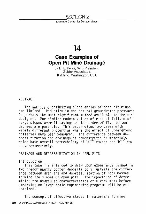
SECTION2 Drainage Control for Surface Mines
14 Case Examples of
Open Pit Mine Drainage by 0. L. Pentz, Vice President,
Golder Associates, Kirkland, Washington, USA
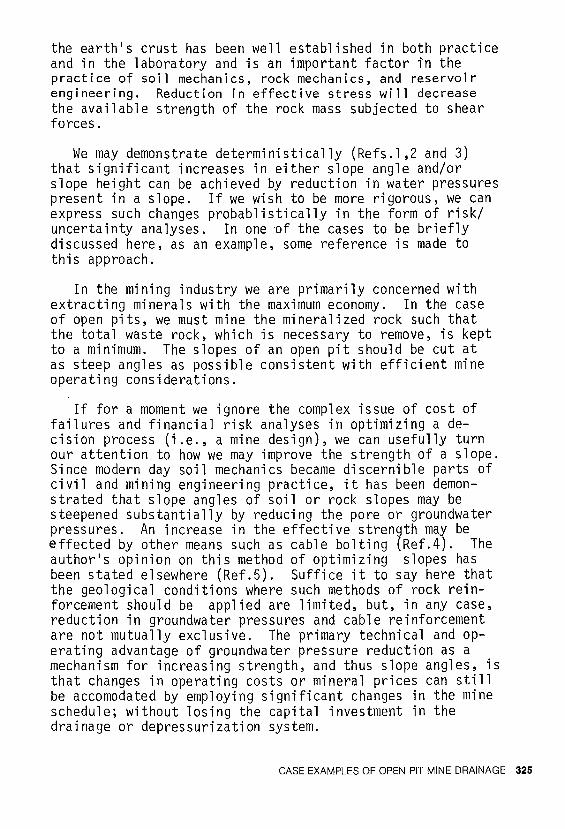
The methods of optimizing slope angles of open pit mines are limited. Reduction in the natural groundwater pressures is perhaps the most significant method available to the mine designer. For similar modest values of risk of failure of large slopes overall savings on the order of five to ten degrees are possible. This paper cites two cases with widely different properties where the effect of underground galleries have been measured. The difference between depressurization and drainage is demons!5ated in materi~2s which have overall permeability of 10 cm/sec and 10 cm/ sec, respectively.
DRAINAGE AND DEPRESSURIZATION IN OPEN PITS
Introduction This paper is intended to draw upon experience gained in
two predominantly copper deposits to illustrate the difference between drainage and depressurization of rock masses forming the slopes of open pits. The importance of determining the hydraulic characteristics of a rock mass before embarking on large-scale engineering programs will be emphasized.
The concept of effective stress in materials forming
324 DRAINAGE CONTROL FOR SURFACE MINES
the earth's crust has been well established in both practice and in the laboratory and is an important factor in the practice of soil mechanics, rock mechanics, and reservoir engineering. Reduction in effective stress will decrease the available strength of the rock mass subjected to shear forces.
We may demonstrate deterministically (Refs.l ,2 and 3) that significant increases in either slope angle and/or slope height can be achieved by reduction in water pressures present in a slope. If we wish to be more rigorous, we can express such changes probablistically in the form of risk/ uncertainty analyses. In one of the cases to be briefly discussed here, as an example, some reference is made to this approach.
In the mining industry we are primarily concerned with extracting minerals with the maximum economy. In the case of open pits, we must mine the mineralized rock such that the total waste rock, \'Jhich is necessary to remove, is kept to a minimum. The slopes of an open pit should be cut at as steep angles as possible consistent with efficient mine operating considerations.
If for a moment we ignore the complex issue of cost of failures and financial risk analyses in optimizing a decision process (i.e., a mine design), we can usefully turn our attention to how we may improve the strength of a slope. Since modern day soil mechanics became discernible parts of civil and mining engineering practice, it has been demonstrated that slope angles of soil or rock slopes may be steepened substantially by reducing the pore or groundwater pressures. An increase in the effective strength may be effected by other means such as cable bolting (Ref.4). The author's opinion on this method of optimizing slopes has been stated elsewhere (Ref.5). Suffice it to say here that the geological conditions where such methods of rock reinforcement should be applied are limited, but, in any case, reduction in groundwater pressures and cable reinforcement are not mutually exclusive. The primary technical and operating advantage of groundwater pressure reduction as a mechanism for increasing strength, and thus slope angles, is that changes in operating costs or mineral prices can still be accomodated by employing significant changes in the mine schedule; without losing the capital investment in the drainage or depressurization system.
CASE EXAMPLES OF OPEN PIT MINE DRAINAGE 325
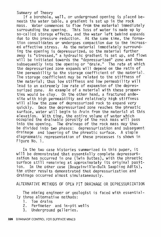
Summary of Theory If a borehole, well, or underground opening is placed be
neath the water table, a gradient is set up in the rock mass. Water commences to fl ow from the materi a 1 immediately surrounding the opening. This loss of water is made up by so-called storage effects, and the water left behind expands due to the pressure reduction. At the same time, the formation consolidates or undergoes compaction due to the increased effective stress. As the material immediately surrounding the opening is depressurized, so the material further away is 11 stressed,u a hydraulic gradient is set up, and flows will be initiated towards the 11 depressurized 11 zone and then subsequently into the opening or 11 drain. 11 The rate at which the depressurized zone expands will depend on the ratio of the permeability to the storage coefficient of the material. The storage coefficient may be related to the stiffness of the material; thus low stiffness and low permeability will lead to an extremely low rate of expansion of the depressurized zone. An example of a material with these properties would be clay. On the other hand, a fractured andesite with high permeability and relatively high stiffness will allow the zone of depressurized rock to expand very quickly. Once the depressurized zone reaches the phreatic surface, water will begin to drain from the material at this elevation. With time, the entire volume of water which occupied the drainable porosity of the rock mass will pass into the opening. The drainage of the rock mass may thus be divided into two phases: depressurization and subsequent drainage and lowering of the phreatic surface. A simple diagrammatic representation of these processes is shown in Figure No. 1.
In the two case histories summarized in this paper, it will be demonstrated that essentially complete depressurization has occurred in one (Twin Buttes), with the phraetic surface still remaining at approximately its original position. In the other case (Bougainville-Bulk Sampling Adits), the other results demonstrated that depressurization and drainage occurred almost simulataneously.
ALTERNATIVE METHODS OF OPEN PIT DRAINAGE OR DEPRESSURIZATION
The mining engineer or geologist is faced with essential-ly three alternative methods:
1. Toedrains 2. Perimeter .and in-pit wells 3. Underground galleries.
326 DRAINAGE CONTROL FOR SURFACE MINES
6 6 DRAINAGE
DISCHARGE
Figure No. l,
\ I \
K varoMI R. \ Ponguno l'r. / _;,----------__ y--- ----
Figure No. 2,
PRESSURE DIAGRAM PRESSURE DECAY DIAGRAM
\\ No Drainage
I\ ,, I \ I \ I \ \ \
\ \ I \
Drain Cock 1/3 open
Drain Cock 2/3 open
Drain Cock fully open
Original Conditions
Rapid Equilibration to New, (Drained) Condition
Drain Cock partially open
DRAINAGE AND DEPRESSURIZATION MODEL
\l \"
PLAN SKETCH OF BOUGAINVILLE DEPOSIT AREA
CASE EXAMPLES OF OPEN PIT MINE DRAINAGE 327
The first and last categories have the advantage of being effectively passive, that is, gravity driven and thus after construction require minimal maintenance. If the rock mass is highly permeable and the hydraulic barriers such as faults are say hundreds of feet apart, then perimeter wells may present a practical solution. However, both toe drains and in-pit wells suffer the disadvantage of interfering with mining operations and require replacement as the pit expands. The toe drains also suffer from a further disadvantage that they cannot be constructed prior to mining the pit slope.
Underground galleries have often been favored for use in high slopes by the author even though the initial capital cost is relatively high because of the efficiency of the system. The possibility also exists to couple an underground gallery system with a surface run-off sump collection system.
The example of the Twin Buttes Mine quoted below indicates that where a real commitment and case is made for optimizing pit slopes, then a drainage gallery system will ensure that an effective depressurization program can be carried out.
Finally, it should be pointed out that while a drainage gallery has many advantages, this does not preclude the use of toe drains and wells in addition. Also, for local potential instability, toe drains have proved to be very successful in halting slides along highways and in some open pits (Ref. l).
CASE HISTORY A - BOUGAINVILLE FEASIBILITY STUDY
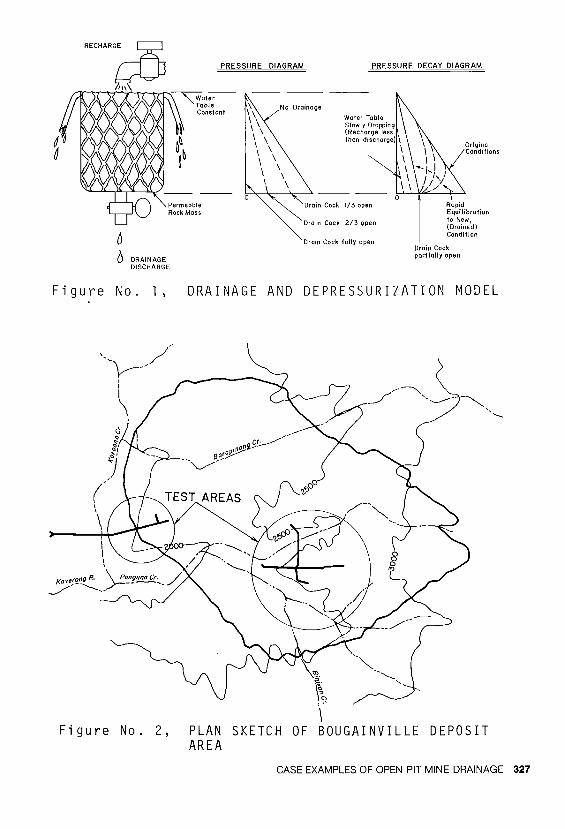
Prior to making a decision on the investment associated with the Bougainville Copper Deposit in Papua and New Guinea, a large scale diamond drilling and bulk sampling program was carried out to determine the nature and limits of the grade distribution (Ref. 6). Associated with this study a large geotechnical program was carried out to evaluate a variety of factors including slope angles. The geotechnical study utilized diamond drillholes for mineral evaluation purposes and some additional special purpose engineering holes. Simple probe tests (inflow) were performed to evaluate permeability in a variety of holes over specified lengths (l to 2 meters). The majority of the groundwater information was, however, obtained from instrumentation of two bulk sampling adits; the Pan Adit and the Western Adit (see Figure No. 2). The effect of.driving these
328 DRAINAGE CONTROL FOR SURFACE MINES
adits on the preexisting groundwater conditions was monitored by measuring the discharge at the portal and several additional points within the adits and by also measuring the response of open holes and sealed piezometers. The piezometers were set in the line of the adits and on either side of centerline of the adits prior to construction.
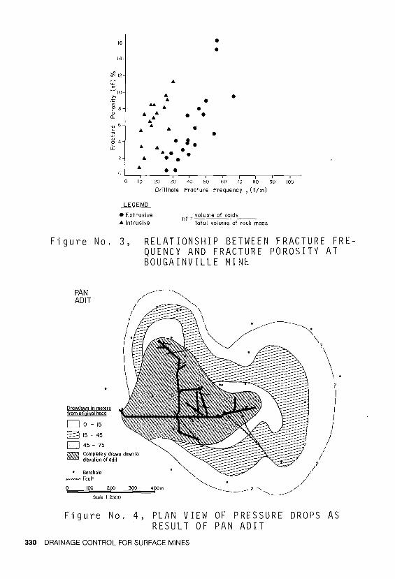
The Bougainville deposit is characterized by a high frequency of jointing in intrusive and extrusive rocks (andeoite and diorites, granodiorites are the predominant rock types). Typically, the rock fractures have a frequency from 10 to 70 fractures per meter and associated high porosity (see Figure No. 3, Ref. 7). The fracturing shows some directional concentrations but this did not preclude joints being measured in exposures in any orientation. The majority of joints were however, measured at angles of greater than 60 degrees. The joints exposed in the test regions of the two adits were open and fresh for the most part. In addition to the joints, the rock mass at Bougainville was found to be interspersed by some predominantly steeply dipping clay filled faults. The results from the two adits may be summarized as follows:
Pan Adit
l. Full drainage occurred almost instantaneously, i.e., there was no discernable depressurization phase. Steady state was reached within 2 to 3 weeks at any point which was monitored.
2. The zone of rock which was drained to approximately the elevation of the adit extended beyond the immediate confines of the underground openings (see Figure No. 4).
3. When clay filled structures were penetrated as mining progressed, sudden responses in piezometric head (see Figure No. 5) were measured accompanied by sudden increases in inflow in the adit.
4. A maximum rate of some 100,000 gallons per CASE EXAMPLES OF OPEN PIT MINE DRAINAGE 329
16
14
~ 12
• • . ' . • • • • • • •
• •
• • •
• •
•
•
0 I 0 20 30 40 50 60 70 BO 90 100
Drill hole Fracture Frequency , ( f/m)
LEGEND
•Extrusive •Intrusive
nf =volume of voids total volume of rock mass
Figure No. 3,
PAN ADJT
Drawdown in meters from original head
Do -15
E8 15 - 45
D 45 - 15
~ ~cit~~e~1 ~da" c1own 1o
• Borehole ............... Fault
0 100 200 300
S<ole L2500
RELATIONSHIP BETWEEN FRACTURE FREQUENCY AND FRACTURE POROSITY AT BOUGAINVILLE MINE
400m
Figure No. 4, PLAN VIEW OF PRESSURE DROPS AS RESULT OF PAN ADIT
330 DRAINAGE CONTROL FOR SURFACE MINES
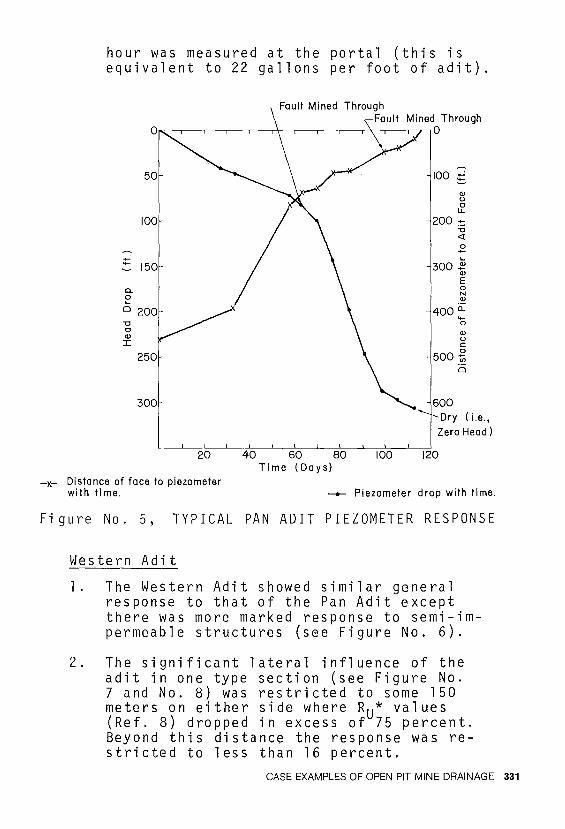
hour was measured at the portal (this is equivalent to 22 gallons per foot of adit) .
50
JOO
...; - J50 ~
0.
~ 0 200 "C c Q)
:r: 250
300
20
-x- Distance of face to piezometer with time.
40 60 80 100 Time (Days)
JOO ...; ~
Q) u c
LL
200 ·-= "C <l'.
.2
300 ~ Q)
E 0 N Q)
400 a:: -0
Q)
u c:
500 ti Ci
Dry. (i.e., Zero Head)
120
--+- Piezometer drop with time.
Figure No. 5, TYPICAL PAN ADIT PIEZOMETER RESPONSE
Western Adit
1. The Western Adit showed similar general response to that of the Pan Adit except there was more marked response to semi-impermeable structures (see Figure No. 6).
2. The significant lateral influence of the adit in one type section (see Figure No. 7 and No. 8) was restricted to some 150 meters on either side where Ru* values (Ref. 8) dropped in excess of 75 percent. Beyond this distance the response was restricted to less than 16 percent.
CASE EXAMPLES OF OPEN PIT MINE DRAINAGE 331
2050
2000
u ~
~1900 N Q)
a:: b c 0
:;: c > Q)
wl800
1700
Elevation of Piezometer
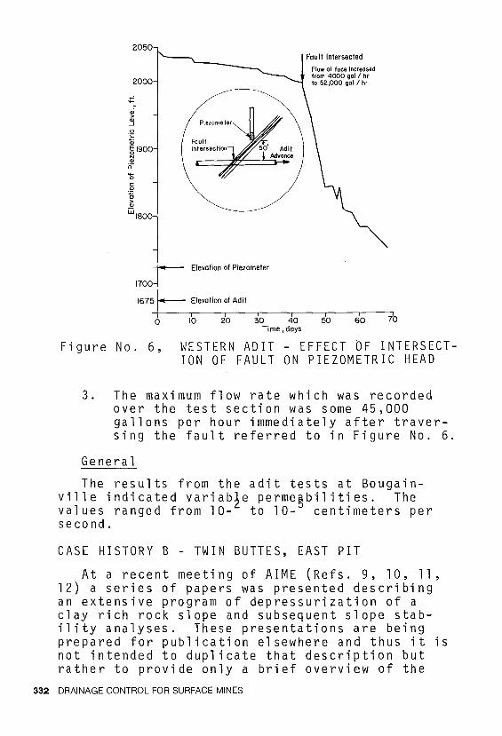
Fau It Intersected
Flow at -face increased from 4000 gol / hr lo 52,000 gol /hr
1675 Elevation of Adit
0 10 20 30 40 50 60 Time, days
70
Figure No. 6, WESTERN ADIT - EFFECT OF INTERSECTION OF FAULT ON PIEZOMETRIC HEAD
3. The maximum flow rate which was recorded over the test section was some 45,000 gallons per hour immediately after traversing the fault referred to in Figure No. 6.
General
The results from the adit tests at Bougainville indicated variab~e perme~bilities. The values ranged from 10- to 10- centimeters per second.
CASE HISTORY B - TWIN BUTTES, EAST PIT
At a recent meeting of AIME (Refs. 9, 10, 11, 12) a series of papers was presented describing an extensive program of depressurization of a clay rich rock slope and subsequent slope stability analyses. These presentations are being prepared for publication elsewhere and thus it is not intended to duplicate that description but rather to provide only a brief overview of the
332 DRAINAGE CONTROL FOR SURFACE MINES
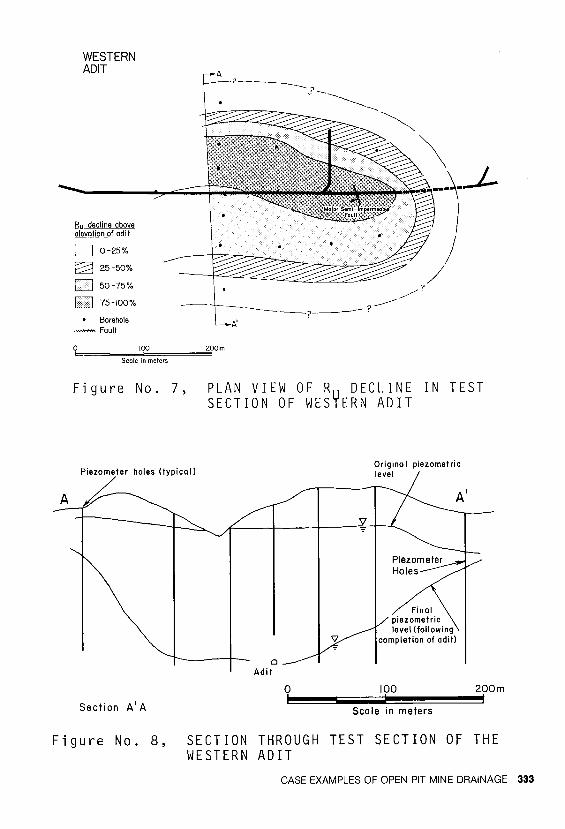
WESTERN ADIT
Bu decline above elevation of adi t
D 0-25%
~ 25-50%
D so-75%
75-100%
• Borehole -Fault
Scale in meters
Figure No. 7,
A -?-------? ,. ~ _________ ___
---~
__ ? ___ ? _______ /
A'
\ ---\-1-
/ J
/ ?
PLAN VIEW OF Ry DECLINE IN TEST SECTION OF WES ERN ADIT
Piezometer holes (typical) Origino I piezometric level
A/-
Section A' A
Figure No. 8,
0 Adil
0 100 200m
Scale in meters
SECTION THROUGH TEST SECTION OF THE WESTERN ADIT
CASE EXAMPLES OF OPEN PIT MINE DRAINAGE 333
salient characteristics of the project.
The east slope of the East Pit of the Twin Buttes Mine in Arizona is geologically characterized by a paleozoic sequence (typically limestones, siltstones) containing the ore and separated by a major fault zone from the waste mesozoics (arkoses and porphyries). This fault zone contains several well defined semivertical clay filled structures and in some 200 feet wide zone. Overlying the bedrock is an alluvium cap which exceeds some 400 feet in vertical thickness.
As a result of several geotechnical and mining considerations, it was decided in 1975 to optimize the slope angles to be formed in the weak and relatively impermeable mesozoics. After several unsuccessful attempts at using toe drains, an extensive underground adit system was driven with some 72 piezometers installed in predominantly surface drilled vertical holes in a manner such that the project could be monitored from a standpoint of reduction in groundwater pressures. A system of installing pneumatic piezometers was developed (Ref. 13) such that up to 4 piezometers could be installed to depths of up to 900 feet.
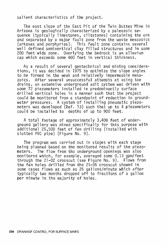
A total footage of approximately 3,400 feet of underground gallery was mined specifically for this purpose with additional 25,500 feet of fan drilling (installed with slotted PVC pipe) (Figure No. 9).
The program was carried out in stages with each stage being planned based on the monitored results of the piezometers. The flow from the underground openings was also monitored which, for example, averaged some 0.13 gpm/feet through the 21-02 crosscut (see Figure No. 9). Flows from the fan holes drilled from the 21-05 crosscut showed in some cases flows as much as 25 gallons/minute which after typically two months dropped off to fractions of a gallon per minute in the majority of holes.
334 DRAINAGE CONTROL FOR SURFACE MINES
•-Surface piezomeler mstallolion
Depressuri.zotion holes
Drill station
Crosscut
Figure No. 9, PLAN OF DEPRESSURIZATION UNDERGROUND LAYOUT
The groundwater pressures response of the rock mass and primary conclusions may be summarized as follows:
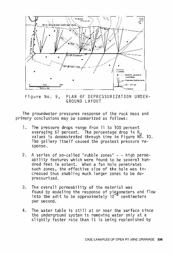
1. The pressure drops range from 11 to 100 percent averaging 67 percent. The percentage drop in R values is demonstrated through time in Figure NH. 10. The gallery itself caused the greatest pressure response.
2. A series of so-called "rubble zones" - - high permeability features which were found to be several hundred feet in extent. When a fan hole penetrates such zones, the effective size of the hole was increased thus enabling much larger zones to be depressurized.
3. The overall permeability of the material was found by modeling the response of pi~5ometers and flow into the adit to be approximately 10 centimeters per second.
4. The water table is still at or near the surface since the underground system is removing water only at a slightly faster rate than it is being replenished by
CASE EXAMPLES OF OPEN PIT MINE DRAINAGE 335
Ru Decline Above 2100 Level
1mm:m::rn 76% - 100%
F<. I 51% - 15%
~::::::::::! 26% - 50%
~ 6% -25%
D 0% -5%
Figure No. 10, Ru PLOTS - FEBRUARY 11' 1978 NOVEMBER 22, 1978
336 DRAINAGE CONTROL FOR SURFACE MINES
2600
(.) 2400 ~ c: -o "'·-
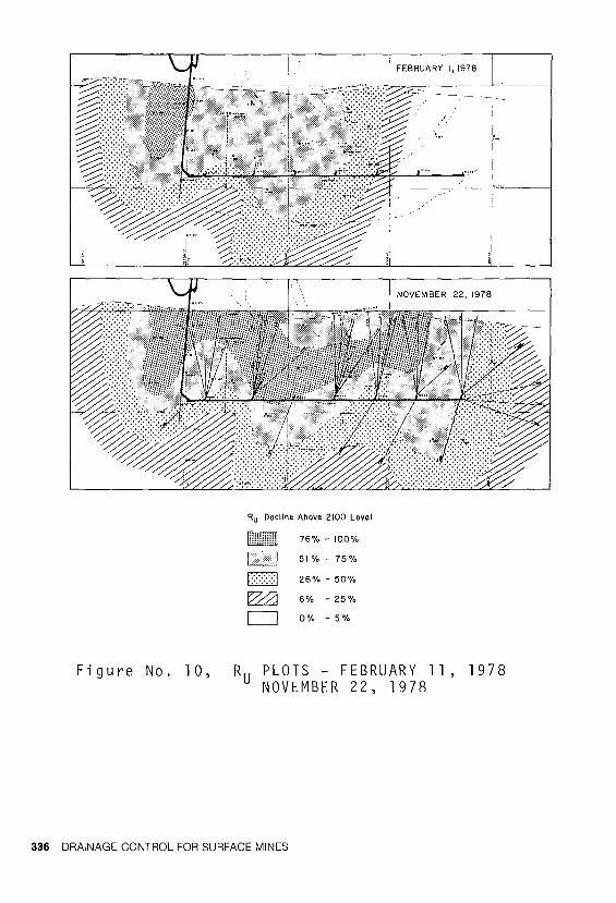
rainfall and infiltration. Accordingly, very slow pressure drops are continuing to be noted, as shown typically in Figure No. 11.
BOREHOLE P-957
Open Hole
P-3
~ 0 2200 N > ~ !j P-2
"' "' o::w P-1
2000,.._ .... .... .... .... .... .... CD CD CD CD "' CD CD .... .... .... .... .... .... .... .... .... .... .... .... .... .... '- '- '- a;. d ~ '- -::::: '- '- '- '- '- -;::: w .... CD - ~ "' "' 'I' "' <!)
Time, months
Figure No. 11, TYPICAL PIEZOMETER RESPONSE TO ADIT SYSTEM
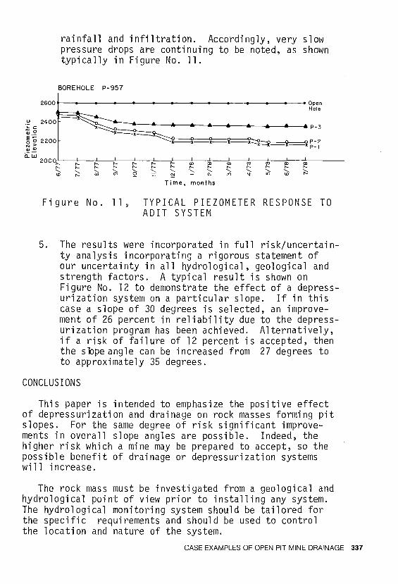
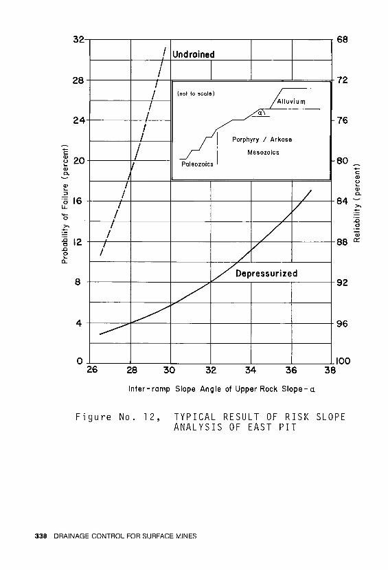
5. The results were incorporated in full risk/uncertainty analysis incorporating a rigorous statement of our uncertainty in all hydrological, geological and strength factors. A typical result is shown on Figure No. 12 to demonstrate the effect of a depressurization system on a particular slope. If in this case a slope of 30 degrees is selected, an improvement of 26 percent in reliability due to the depressurization program has been achieved. Alternatively, if a risk of failure of 12 percent is accepted, then the sbpe angle can be increased from 27 degrees to to approximately 35 degrees.
CONCLUSIONS
This paper is intended to emphasize the positive effect of depressurization and drainage on rock masses forming pit slopes. For the same degree of risk significant improvements in overall slope angles are possible. Indeed, the higher risk which a mine may be prepared to accept, so the possible benefit of drainage or depressurization systems wi 11 increase.
The rock mass must be investigated from a geological and hydrological point of view prior to installing any system. The hydrological monitoring system should be tailored for the specific requirements and should be used to control the location and nature of the system.
CASE EXAMPLES OF OPEN PIT MINE DRAINAGE 337
-c:
32
28
24
~ 20 ..... Q) c.
Q) ..... :::i
'5 16 LL
-g 12 ..c 0 .....
a..
8
4
0
I I
I I
/
26
I Undrained I I
I
~ I (not to scole)
I ~
I I Porphyry I Arkose
I I
Paleozoics I Mesozolcs
I
/ / /
/
/ /
v
Voepressurized
/ ~
28 30 32 34 36
Inter- ramp Slope Ang le of Upper Rock Slope - d.
68
72
76
80 -c: Q) u ..... Q) c.
84:.
..c 0
Q)
88 0:
92
96
100 38
Figure No. 12, TYPICAL RESULT OF RISK SLOPE ANALYSIS OF EAST PIT
338 DRAINAGE CONTROL FOR SURFACE MINES
Finally a plea is made to those geologists and engineers involved in exploration and feasibility studies of mineral deposits to maximize the information gathered from boreholes and bulk sampling adits so that substantially more reliable data may be obtained for evaluating ore as opposed to mineral reserves.
ACKNOWLEDGMENTS
I wish to acknowledge the Conzinc Rio Tinto Company, and in particular, M.R.L. BlackvJell, for his help during the Bougainville Copper Feasibility Studies and also to the staff past and present of Anamax Mining Company for permission to use the data presented on Twin Buttes.
CASE EXAMPLES OF OPEN PIT MINE DRAINAGE 339
REF ERE NC ES
l. Brawner, C.O. 1974. Rock Mechanics in Open Pit Mining. In Advances in Rock Mechanics: Proceedings of the 3rd Congress of the International Society for Rock Mechanics, Denver, V. l, pp. 755-773. Washington, D.C,: National Academy of Sciences.
2. Hoek, E. and J. Bray. 1977. Rock Slope Engineering. Rev. 2nd Ed. London: The Institution of Mining and Metallurgy.
3. Sharp, J.C. and T. Maini. 1972. Fundamental Considerations on the Hydraulic Characteristics of Joints in Rocks. In Proc. Symposium on Percolation Through FTSsured Rock, International Society for Rock Mechanics, Stuttgart, pp. Tl-Fl-Tl-F15.
4. Seegmiller, B. 1974. How Cable Bolt Stabilization may Benefit Open Pit Operations. Mining Engineering, V. 26, No. 12.
5. Pentz, D. and P. Hodges. 1976. Geotechnical Factors in Open Pit Mine Design. In Site Characterization: 17th U.S. SympoSTum on Rock Mechanics, Snowbird, Utah, V. 81, pp.All3-Al20.
6. Stephenson, H.H. ed. (1973). Bougainville -The Establishment of a Copper Mine. Kilda, Australia: Construction, Mining, Engineering Publications.
7. Ashby, J. 1979. Personal Communication.
8. Bishop, A.W. and N. Morgenstern. 1960. Stability Coefficients for Earth Dams. Geotechnique, V. 10, No. 4, pp. 129-150.
9. Miller, I. and G. Deardorff. 1979. Bedrock Geohydrology of East End Fault Zone Slopes at Twin Buttes. Paper presented at the AIME Annual Meeting, New Orleans, Feb. 18-22.
10. Pentz, D. and P. Hodges. 1979. Summary of Objectives and Achievements of Slope Design at
340 DRAINAGE CONTROL FOR SURFACE MINES
Twin Buttes. Paper presented at the AIME Annual Meeting, New Orleans, February 18-22.
11. Byrne, J. and D. Pentz. 1979. Stability Analysis and Mining Implications for Twin Buttes. Paper presented at the AIME Annual Meeting, New Orleans, February 18-22.
12. Rippere, K. and Charles Barter. Engineering Geology of the East End Fault Zone Slope Desing Program at Twin Buttes.
13. Deardorff, G.B., A.M. Lumsden and W.M. Hefferon. 1979. Pneumatic Piezometers: Multiple and Single Installations in Vertical and Inclined Boreholes. Paper submitted for publication.
CASE EXAMPLES OF OPEN PIT MINE DRAINAGE 341