Embed Size (px)
Citation preview
Case studies in steels
Metallurgical detective work after a boiler explosion
Case studies in steels 133
Chapter 13Case studies in steels
Metallurgical detective work after a boiler explosion
The first case study shows how a knowledge of steel microstructures can help us tracethe chain of events that led to a damaging engineering failure.
The failure took place in a large water-tube boiler used for generating steam in achemical plant. The layout of the boiler is shown in Fig. 13.1. At the bottom of theboiler is a cylindrical pressure vessel – the mud drum – which contains water andsediments. At the top of the boiler is the steam drum, which contains water and steam.The two drums are connected by 200 tubes through which the water circulates. Thetubes are heated from the outside by the flue gases from a coal-fired furnace. Thewater in the “hot” tubes moves upwards from the mud drum to the steam drum, andthe water in the “cool” tubes moves downwards from the steam drum to the muddrum. A convection circuit is therefore set up where water circulates around the boilerand picks up heat in the process. The water tubes are 10 m long, have an outsidediameter of 100 mm and are 5 mm thick in the wall. They are made from a steel ofcomposition Fe–0.18% C, 0.45% Mn, 0.20% Si. The boiler operates with a workingpressure of 50 bar and a water temperature of 264°C.
Fig. 13.1. Schematic of water-tube boiler.
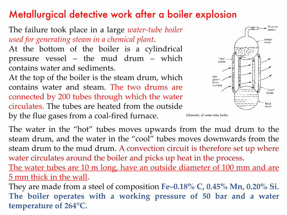
The failure took place in a large water-tube boilerused for generating steam in a chemical plant.At the bottom of the boiler is a cylindricalpressure vessel – the mud drum – whichcontains water and sediments.At the top of the boiler is the steam drum, whichcontains water and steam. The two drums areconnected by 200 tubes through which the watercirculates. The tubes are heated from the outsideby the flue gases from a coal-fired furnace.
The water in the “hot” tubes moves upwards from the mud drum to thesteam drum, and the water in the “cool” tubes moves downwards from thesteam drum to the mud drum. A convection circuit is therefore set up wherewater circulates around the boiler and picks up heat in the process.The water tubes are 10 m long, have an outside diameter of 100 mm and are5 mm thick in the wall.They are made from a steel of composition Fe–0.18% C, 0.45% Mn, 0.20% Si.The boiler operates with a working pressure of 50 bar and a watertemperature of 264°C.
134 Engineering Materials 2
Fig. 13.2. Schematic of burst tube.
In the incident some of the “hot” tubes became overheated, and started to bulge.Eventually one of the tubes burst open and the contents of the boiler were dischargedinto the environment. No one was injured in the explosion, but it took several monthsto repair the boiler and the cost was heavy. In order to prevent another accident, amaterials specialist was called in to examine the failed tube and comment on thereasons for the failure.
Figure 13.2 shows a schematic diagram of the burst tube. The first operation was tocut out a 20 mm length of the tube through the centre of the failure. One of the cutsurfaces of the specimen was then ground flat and tested for hardness. Figure 13.3shows the data that were obtained. The hardness of most of the section was about2.2 GPa, but at the edges of the rupture the hardness went up to 4 GPa. This indicates(see Fig. 13.3) that the structure at the rupture edge is mainly martensite. However,away from the rupture, the structure is largely bainite. Hardness tests done on a spareboiler tube gave only 1.5 GPa, showing that the failed tube would have had a ferrite+ pearlite microstructure to begin with.
In order to produce martensite and bainite the tube must have been overheated to atleast the A3 temperature of 870°C (Fig. 13.4). When the rupture occurred the rapidoutrush of boiler water and steam cooled the steel rapidly down to 264°C. The coolingrate was greatest at the rupture edge, where the section was thinnest: high enough toquench the steel to martensite. In the main bulk of the tube the cooling rate was less,which is why bainite formed instead.
The hoop stress in the tube under the working pressure of 50 bar (5 MPa) is 5 MPa× 50 mm/5 mm = 50 MPa. Creep data indicate that, at 900°C and 50 MPa, the steelshould fail after only 15 minutes or so. In all probability, then, the failure occurred bycreep rupture during a short temperature excursion to at least 870°C.
How was it that water tubes reached such high temperatures? We can give twoprobable reasons. The first is that “hard” feed water will – unless properly treated –
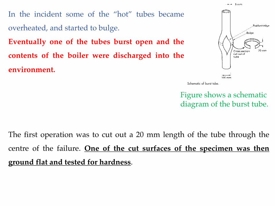
In the incident some of the “hot” tubes became
overheated, and started to bulge.
Eventually one of the tubes burst open and the
contents of the boiler were discharged into the
environment.
The first operation was to cut out a 20 mm length of the tube through the
centre of the failure. One of the cut surfaces of the specimen was then
ground flat and tested for hardness.
Figure shows a schematicdiagram of the burst tube.

Hardness tests done on a spare boiler tube gave only 1.5 GPa, showing
that the failed tube would have had a ferrite + pearlite microstructure to
begin with.
Case studies in steels 135
Fig. 13.3. The hardness profile of the tube.
Fig. 13.4. Part of the iron–carbon phase diagram.
The hardness of most of the
section was about 2.2 GPa, but at
the edges of the rupture the
hardness went up to 4 GPa. This
indicates that the structure at the
rupture edge is mainly martensite.
However, away from the rupture,
the structure is largely bainite

In order to produce martensite and bainite the tube must
have been overheated to at least the A3temperature of 870°C.
When the rupture occurred the rapid outrush of boiler water
and steam cooled the steel rapidly down to 264°C. The
cooling rate was greatest at the rupture edge, where the
section was thinnest: high enough to quench the steel to
martensite. In the main bulk of the tube the cooling rate was
less, which is why bainite formed instead.
Case studies in steels 135
Fig. 13.3. The hardness profile of the tube.
Fig. 13.4. Part of the iron–carbon phase diagram.The hoop stress in the tube under the working pressure of 50 bar (5 MPa) is 5 MPa ×
50 mm/5 mm = 50 MPa.
Creep data indicate that, at 900°C and 50 MPa, the steel should fail after only 15
minutes or so.
In all probability, then, the failure occurred by creep rupture during a short
temperature excursion to at least 870°C.

We can give two probable reasons.
The first is that “hard” feed water will – unless
properly treated – deposit scale inside the tubes.
This scale will help to insulate the metal from the boiler
water and the tube will tend to overheat.
Secondly, water circulation in a natural convection
boiler can be rather hit-and-miss; and the flow in
some tubes can be very slow. Under these conditions
a stable layer of dry steam can form next to the inner
wall of the tube and this, too, can be a very effective
insulator.
136 Engineering Materials 2
Fig. 13.5. Temperature distribution across the water-tube wall.
deposit scale inside the tubes (Fig. 13.5). This scale will help to insulate the metal fromthe boiler water and the tube will tend to overheat. Secondly, water circulation in anatural convection boiler can be rather hit-and-miss; and the flow in some tubes can bevery slow. Under these conditions a stable layer of dry steam can form next to theinner wall of the tube and this, too, can be a very effective insulator.
Welding steels together safely
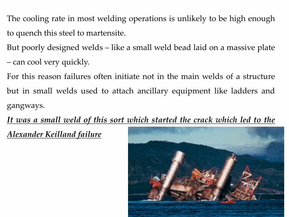
Many steel structures – like bridges, storage tanks, and ships – are held together bywelds. And when incidents arise from fast fractures or fatigue failures they can oftenbe traced to weaknesses in the welds. The sinking of the Alexander Keilland oil plat-form in 1980 is an example.
Figure 13.6 is a schematic of a typical welding operation. An electric arc is struckbetween the electrode (which contains filler metal and flux) and the parent plates. Theheat from the arc melts the filler metal which runs into the gap to form a molten pool.Although the pool loses heat to the surrounding cold metal this is replaced by energyfrom the arc. In fact some of the parent material is melted back as well. But as the arcmoves on, the molten steel that it leaves behind solidifies rapidly, fusing the twoplates together. Figure 13.6 shows how the temperature in the metal varies with dis-tance from the weld pool. Because the electrode moves along the weld, the isotherms
How was it that water tubes reached such high temperatures?

Welding steels together safelyMany steel structures – like bridges, storage tanks, and ships – are held
together by welds. And when incidents arise from fast fractures or
fatigue failures they can often be traced to weaknesses in the welds.
The sinking of the Alexander Keilland oil plat- form in 1980 is an example.Case studies in steels 137
Fig. 13.6. Schematic of a typical welding operation.
bunch up in front of the pool like the bow wave of a ship; behind the pool they arespaced more widely. The passage of this thermal “wave” along the weld leads to veryrapid heating of the metal in front of the weld pool and slightly less rapid cooling of themetal behind (Fig. 13.7). The section of the plate that is heated above ≈650°C has itsmechanical properties changed as a result. For this reason it is called the heat-affectedzone (HAZ).
The most critical changes occur in the part of the HAZ that has been heated abovethe A3 temperature (Fig. 13.7). As the arc moves on, this part of the HAZ can cool asquickly as 100°C s−1. With a fine-grained carbon steel this should not be a problem: theCCR is more than 400°C s−1 (Fig. 12.1) and little, if any, martensite should form. Butsome of the steel in the HAZ goes up to temperatures as high as 1400°C. At suchtemperatures diffusion is extremely rapid, and in only a few seconds significant graingrowth will take place (see Chapter 5). The CCR for this grain-growth zone will be
Fig. 13.7. The left-hand graph shows how the temperature at one point in the parent plate changes as thewelding arc passes by. The point chosen here is quite close to the edge of the plate, which is why it reachesa high peak temperature. A point further away from the edge would not reach such a high peak temperature.
Case studies in steels 137
Fig. 13.6. Schematic of a typical welding operation.
bunch up in front of the pool like the bow wave of a ship; behind the pool they arespaced more widely. The passage of this thermal “wave” along the weld leads to veryrapid heating of the metal in front of the weld pool and slightly less rapid cooling of themetal behind (Fig. 13.7). The section of the plate that is heated above ≈650°C has itsmechanical properties changed as a result. For this reason it is called the heat-affectedzone (HAZ).
The most critical changes occur in the part of the HAZ that has been heated abovethe A3 temperature (Fig. 13.7). As the arc moves on, this part of the HAZ can cool asquickly as 100°C s−1. With a fine-grained carbon steel this should not be a problem: theCCR is more than 400°C s−1 (Fig. 12.1) and little, if any, martensite should form. Butsome of the steel in the HAZ goes up to temperatures as high as 1400°C. At suchtemperatures diffusion is extremely rapid, and in only a few seconds significant graingrowth will take place (see Chapter 5). The CCR for this grain-growth zone will be
Fig. 13.7. The left-hand graph shows how the temperature at one point in the parent plate changes as thewelding arc passes by. The point chosen here is quite close to the edge of the plate, which is why it reachesa high peak temperature. A point further away from the edge would not reach such a high peak temperature.
The passage of this thermal“wave” along the weld leads tovery rapid heating of the metal infront of the weld pool andslightly less rapid cooling of themetal behind. The section of theplate that is heated above ≈ 650°Chas its mechanical propertieschanged as a result. For thisreason it is called the heat-affectedzone (HAZ).
The most critical changes occur in the part of the HAZ that has been heated
above the A3 temperature. As the arc moves on, this part of the HAZ can
cool as quickly as 100°C s−1. With a fine-grained carbon steel this should not
be a problem: the (critical cooling rate, CCR) is more than 400°C s−1 and
little, if any, martensite should form. But some of the steel in the HAZ goes
up to temperatures as high as 1400°C. At such temperatures diffusion is
extremely rapid, and in only a few seconds significant grain growth will take
place.
The CCR for this grain-growth zone will be reduced accordingly. In practice, it
is found that martensite starts to appear in the HAZ when the carbon content is
more than 0.5 to 0.6%.

126 Engineering Materials 2
Fig. 12.1. The effect of carbon content and grain size on the critical cooling rate.
Fig. 12.2. Alloying elements make steels more hardenable.
molybdenum (Mo), manganese (Mn), chromium (Cr) or nickel (Ni) (Fig. 12.2). Numer-ous low-alloy steels have been developed with superior hardenability – the ability toform martensite in thick sections when quenched. This is one of the reasons for addingthe 2–7% of alloying elements (together with 0.2–0.6% C) to steels used for things likecrankshafts, high-tensile bolts, springs, connecting rods, and spanners. Alloys withlower alloy contents give martensite when quenched into oil (a moderately rapidquench); the more heavily alloyed give martensite even when cooled in air. Havingformed martensite, the component is tempered to give the desired combination ofstrength and toughness.
Hardenability is so important that a simple test is essential to measure it. The Jominyend-quench test, though inelegant from a scientific standpoint, fills this need. A bar100 mm long and 25.4 mm in diameter is heated and held in the austenite field. Whenall the alloying elements have gone into solution, a jet of water is sprayed onto oneend of the bar (Fig. 12.3). The surface cools very rapidly, but sections of the bar behind

Quenching and tempering is usually limited to steels containing more than
about 0.1% carbon. These steels must be cooled at rates ranging from 100 to
2000°C s−1 if 100% martensite is to be produced. There is no difficulty in
transforming the surface of a component to martensite – we simply quench
the red-hot steel into a bath of cold water or oil.
But if the component is at all large, the surface layers will tend to insulate
the bulk of the component from the quenching fluid. The bulk will cool more
slowly than the CCR and will not harden properly. Worse, a rapid quench
can create shrinkage stresses which are quite capable of cracking brittle,
untempered martensite.
These problems are overcome by alloying. The entire TTT curve is shifted to
the right by adding a small percentage of the right alloying element to the
steel – usually (Mo), (Mn), (Cr) or (Ni)

Jominy test on a steel of mediumhardenability. M = martensite, B =bainite, F = primary ferrite,P = pearlite.
Jominy test on a steel of high hardenability.
Steels: II – alloy steels 127
Fig. 12.3. The Jominy end-quench test for hardenability.
Fig. 12.4. Jominy test on a steel of high hardenability.
the quenched surface cool progressively more slowly (Fig. 12.3). When the whole baris cold, the hardness is measured along its length. A steel of high hardenability willshow a uniform, high hardness along the whole length of the bar (Fig. 12.4). This isbecause the cooling rate, even at the far end of the bar, is greater than the CCR; and thewhole bar transforms to martensite. A steel of medium hardenability gives quite dif-ferent results (Fig. 12.5). The CCR is much higher, and is only exceeded in the first fewcentimetres of the bar. Once the cooling rate falls below the CCR the steel starts totransform to bainite rather than martensite, and the hardness drops off rapidly.
128 Engineering Materials 2
Fig. 12.5. Jominy test on a steel of medium hardenability. M = martensite, B = bainite, F = primary ferrite,P = pearlite.
Solution hardening
The alloying elements in the low-alloy steels dissolve in the ferrite to form a substitutionalsolid solution. This solution strengthens the steel and gives useful additional strength.The tool steels contain large amounts of dissolved tungsten (W) and cobalt (Co) as well,to give the maximum feasible solution strengthening. Because the alloying elementshave large solubilities in both ferrite and austenite, no special heat treatments areneeded to produce good levels of solution hardening. In addition, the solution-hardeningcomponent of the strength is not upset by overheating the steel. For this reason, low-alloy steels can be welded, and cutting tools can be run hot without affecting thesolution-hardening contribution to their strength.
Precipitation hardening
The tool steels are an excellent example of how metals can be strengthened by precipita-tion hardening. Traditionally, cutting tools have been made from 1% carbon steelwith about 0.3% of silicon (Si) and manganese (Mn). Used in the quenched and tem-pered state they are hard enough to cut mild steel and tough enough to stand up to theshocks of intermittent cutting. But they have one serious drawback. When cuttingtools are in use they become hot: woodworking tools become warm to the touch, butmetalworking tools can burn you. It is easy to “run the temper” of plain carbon

Weldable structural steel to BS 4360 grade 43A
BS 4360 is the structural steel. Grade 43A has the following specifications: C =
0.25%,Mn = 1.60%, Si = 0.50%; σTS
430 to 510 MPa; σy = 240 MPa
The maximum carbon content of 0.25% is well below the 0.5 to 0.6% that
may give HAZ problems. But, in common with all “real” carbon steels,
4360 contains Mn. This is added to react with harmful impurities like S.Any unreacted Mn dissolves in ferrite where it contributes solid-solution
strengthening and gives increased hardenability. But how do we know
whether our 1.6% of manganese is likely to give HAZ problems? Most
welding codes assess the effect of alloying elements from the empirical
formula
138 Engineering Materials 2
reduced accordingly (Fig. 12.1). In practice, it is found that martensite starts to appearin the HAZ when the carbon content is more than 0.5 to 0.6%.
The last thing that is wanted in a weld is a layer of hard, brittle martensite. It canobviously make the weld as a whole more brittle. And it can encourage hydrogencracking. All welds contain quantities of atomic hydrogen (the molten steel in the weldpool rapidly reduces atmospheric moisture to give iron oxide and hydrogen). Becausehydrogen is such a small atom it can diffuse rapidly through steel (even at roomtemperature) and coalesce to give voids which, in a brittle material like martensite,will grow into cracks. These cracks can then extend (e.g. by fatigue) until they are longenough to cause fast fracture.
Example 1: Weldable structural steel to BS 4360 grade 43A
BS 4360 is the structural steel workhorse. Grade 43A has the following specifications:C ! 0.25%, Mn ! 1.60%, Si ! 0.50%; σTS 430 to 510 MPa; σy " 240 MPa.
The maximum carbon content of 0.25% is well below the 0.5 to 0.6% that may giveHAZ problems. But, in common with all “real” carbon steels, 4360 contains man-ganese. This is added to react with harmful impurities like sulphur. Any unreactedmanganese dissolves in ferrite where it contributes solid-solution strengthening andgives increased hardenability. But how do we know whether our 1.6% of manganeseis likely to give HAZ problems? Most welding codes assess the effect of alloyingelements from the empirical formula
CE C
Mn Cr Mo V Ni Cu
= + + + + + +6 5 15
(13.1)
where CE is the carbon equivalent of the steel. The 1.6% Mn in our steel would thus beequivalent to 1.6%/6 = 0.27% carbon in its contribution to martensite formation in theHAZ. The total carbon equivalent is 0.25 + 0.27 = 0.52. The cooling rate in most weld-ing operations is unlikely to be high enough to quench this steel to martensite. Butpoorly designed welds – like a small weld bead laid on a massive plate – can cool veryquickly. For this reason failures often initiate not in the main welds of a structure butin small welds used to attach ancillary equipment like ladders and gangways. (It wasa small weld of this sort which started the crack which led to the Alexander Keillandfailure.)
Example 2: Pressure vessel steel to A 387 grade 22 class 2
A 387–22(2) is a creep-resistant steel which can be used at about 450°C. It is a standardmaterial for pipes and pressure vessels in chemical plants and oil refineries. The speci-fication is: C ! 0.15%, Mn 0.25 to 0.66%, Si ! 0.50%, Cr 1.88 to 2.62%, Mo 0.85 to 1.15%;σTS 515 to 690 MPa; σy " 310 MPa.
The carbon equivalent for the maximum composition figures given is
CE .
.
. . . .= + + + =0 15
0 666
2 62 1 155
1 01 (13.2)
The total carbon equivalent
is 0.25 + 0.27 = 0.52
The cooling rate in most welding operations is unlikely to be high enough
to quench this steel to martensite.
But poorly designed welds – like a small weld bead laid on a massive plate
– can cool very quickly.
For this reason failures often initiate not in the main welds of a structure
but in small welds used to attach ancillary equipment like ladders and
gangways.
It was a small weld of this sort which started the crack which led to the
Alexander Keilland failure
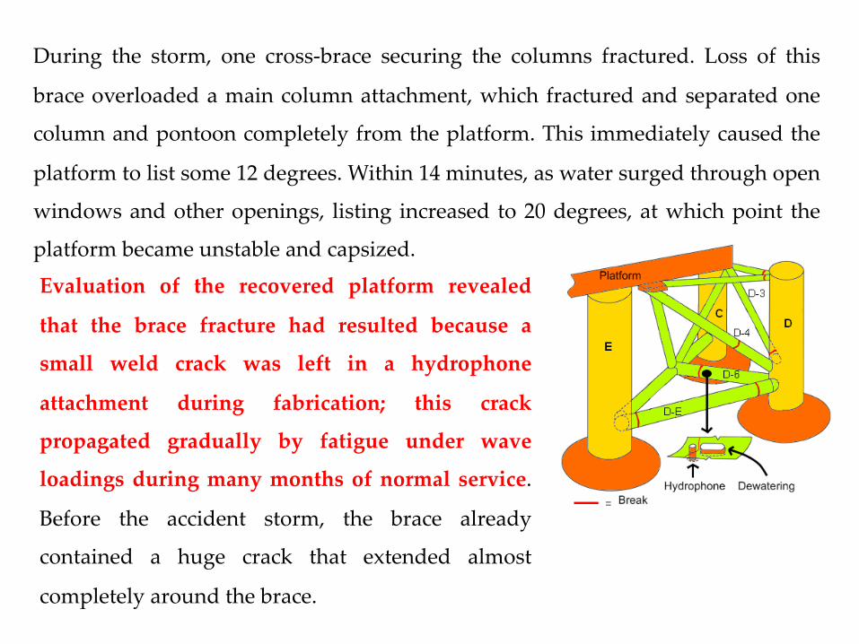
During the storm, one cross-brace securing the columns fractured. Loss of this
brace overloaded a main column attachment, which fractured and separated one
column and pontoon completely from the platform. This immediately caused the
platform to list some 12 degrees. Within 14 minutes, as water surged through open
windows and other openings, listing increased to 20 degrees, at which point the
platform became unstable and capsized.
Evaluation of the recovered platform revealed
that the brace fracture had resulted because a
small weld crack was left in a hydrophone
attachment during fabrication; this crack
propagated gradually by fatigue under wave
loadings during many months of normal service.
Before the accident storm, the brace already
contained a huge crack that extended almost
completely around the brace.

Pressure vessel steel to A 387 grade 22 class 2
A 387–22(2) is a creep-resistant steel which can be used at about 450°C. It is
a standard material for pipes and pressure vessels in chemical plants and
oil refineries. The specification is:
C = 0.15%, Mn 0.25 to 0.66%, Si = 0.50%, Cr 1.88 to 2.62%, Mo 0.85 to 1.15%;
σTS 515 to 690 MPa; σy = 310 MPa.
The carbon equivalent for the maximum composition is
CE = 1.01
The Mn, Cr and Mo in the steel have increased the hardenability
considerably, and martensite is likely to form in the HAZ unless special
precautions are taken.

The cooling rate can be decreased greatly if the parent plate is pre-heated
to ≈350°C before welding starts and slowly cooled after welding, and this
is specified in the relevant welding code.
Imagine yourself, though, as a welder working inside a large pre-heated pressure
vessel: clad in an insulating suit and fed with cool air from outside you can only
stand 10 minutes in the heat before making way for somebody else

The broken hammerDuring breaking up some
concrete slabs with an
hammer a large fragment of
metal broke away. A 1.5 lb
hammer is not heavy enough
for breaking up slabs
The hammer was examined
to see whether the fracture
might have been caused by
faulty heat treatment.
Case studies in steels 139
The Mn, Cr and Mo in the steel have increased the hardenability considerably, andmartensite is likely to form in the HAZ unless special precautions are taken. But thecooling rate can be decreased greatly if the parent plate is pre-heated to ≈350°C beforewelding starts, and this is specified in the relevant welding code. Imagine yourself,though, as a welder working inside a large pre-heated pressure vessel: clad in aninsulating suit and fed with cool air from outside you can only stand 10 minutes in theheat before making way for somebody else!
The case of the broken hammer
The father of one of the authors was breaking up some concrete slabs with an engin-eers’ hammer when a large fragment of metal broke away and narrowly missed hiseye. A 1
12 lb hammer is not heavy enough for breaking up slabs, and he should have
been wearing eye protection, but that is another matter. We examined the hammer tosee whether the fracture might have been caused by faulty heat treatment.
Figure 13.8(a) shows the general shape of the hammer head, and marks the origin ofthe offending fragment. Figure 13.8(b) is a close-up of the crater that the fragment leftbehind when it broke away.
The first thing that we did was to test the hardness of the hammer. The results areshown in Fig. 13.9. The steel is very hard near the striking face and the ball pein, but
Fig. 13.8. (a) General view of hammer head. The origin of the fragment is marked with an arrow.(b) Close-up of crater left by fragment.
140 Engineering Materials 2
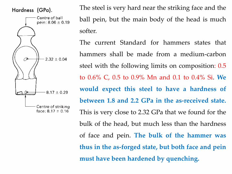
Fig. 13.9. Hardness results for hammer head (GPa).
the main body of the head is much softer. The current Standard for hammers (BS 876,1995) states that hammers shall be made from a medium-carbon forging steel with thefollowing limits on composition: 0.5 to 0.6% C, 0.5 to 0.9% Mn and 0.1 to 0.4% Si. Wewould expect this steel to have a hardness of between 1.8 and 2.2 GPa in the as-received state. This is very close to the figure of 2.32 GPa that we found for the bulk ofthe head, but much less than the hardness of face and pein. The bulk of the hammerwas thus in the as-forged state, but both face and pein must have been hardened byquenching.
We can see from Fig. 11.9 that untempered 0.55% carbon martensite should havea hardness of 8.0 GPa. This is essentially identical to the hardnesses that we foundon the striking face and the ball pein, and suggests strongly that the face had notbeen tempered at all. In fact, the Standard says that faces and peins must be tem-pered to bring the hardness down into the range 5.1 to 6.6 GPa. Presumably experi-ence has shown that this degree of tempering makes the steel tough enough to standup to normal wear and tear. Untempered martensite is far too brittle for hammerheads.
Having solved the immediate problem to our satisfaction we still wondered how themanufacturer had managed to harden the striking faces without affecting the bulk ofthe hammer head. We contacted a reputable maker of hammers who described thesequence of operations that is used. The heads are first shaped by hot forging and thenallowed to cool slowly to room temperature. The striking face and ball pein are finishedby grinding. The striking faces are austenitised as shown in Fig. 13.10 and are thenquenched into cold water. The only parts of the hammers to go above 723°C are theends: so only these parts can be hardened by the quench. The quenched heads are thendried and the ends are tempered by completely immersing the heads in a bath ofmolten salt at 450°C. Finally, the heads are removed from the tempering bath andwashed in cold water. The rather complicated austenitising treatment is needed be-cause the Standard insists that the hardened zone must not extend into the neck of thehammer (Fig. 13.10). You can imagine how dangerous it would be if a hammer brokeclean in two. The neck does not need to be hard, but it does need to be tough.
Hardness (GPa). The steel is very hard near the striking face and the
ball pein, but the main body of the head is much
softer.
The current Standard for hammers states that
hammers shall be made from a medium-carbon
steel with the following limits on composition: 0.5
to 0.6% C, 0.5 to 0.9% Mn and 0.1 to 0.4% Si. We
would expect this steel to have a hardness of
between 1.8 and 2.2 GPa in the as-received state.
This is very close to 2.32 GPa that we found for the
bulk of the head, but much less than the hardness
of face and pein. The bulk of the hammer was
thus in the as-forged state, but both face and pein
must have been hardened by quenching.
Steels: I – carbon steels 119
Fig. 11.8. TTT diagrams for (a) eutectoid, (b) hypoeutectoid and (c) hypereutectoid steels. (b) and (c) show(dashed lines) the C-curves for the formation of primary a and Fe3C respectively. Note that, as the carboncontent increases, both MS and MF decrease.
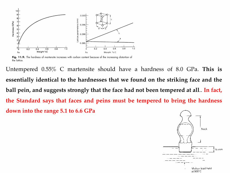
Fig. 11.9. The hardness of martensite increases with carbon content because of the increasing distortion ofthe lattice.
Untempered 0.55% C martensite should have a hardness of 8.0 GPa. This is
essentially identical to the hardnesses that we found on the striking face and the
ball pein, and suggests strongly that the face had not been tempered at all.. In fact,
the Standard says that faces and peins must be tempered to bring the hardness
down into the range 5.1 to 6.6 GPa
Case studies in steels 141
Postscript
Although there is a British Standard for hammers, there is no legislation in the UKwhich compels retailers to supply only standard hammers. It is, in fact, quite difficultto get standard hammers “over the counter”. But reputable makers spot check theirhammers, because they will not knowingly sell improperly heat-treated hammers.
Further reading
K. E. Easterling, Introduction to the Physical Metallurgy of Welding, Butterworth, 1983.D. T. Llewellyn, Steels – Metallurgy and Applications, 2nd edition, Butterworth-Heinemann, 1994.
Problems
13.1 The heat exchanger in a reformer plant consisted of a bank of tubes made froma low-alloy ferritic steel containing 0.2 weight% carbon. The tubes containedhydrocarbon gas at high pressure and were heated from the outside by furnacegases. The tubes had an internal diameter of 128 mm and a wall thickness of7 mm. Owing to a temperature overshoot, one of the tubes fractured and theresulting gas leak set the plant on fire.
When the heat exchanger was stripped down it was found that the tube wallhad bulged over a distance of about 600 mm. In the most expanded region of thebulge, the tube had split longitudinally over a distance of about 300 mm. At theedge of the fracture the wall had thinned down to about 3 mm. Metallurgicalsections were cut from the tube at two positions: (i) immediately next to thefracture surface half-way along the length of the split, (ii) 100 mm away from theend of the split in the part of the tube which, although slightly expanded, wasotherwise intact.
Fig. 13.10. Austenitising a striking face.