Embed Size (px)
Citation preview

www.sgh.com
DES
IGN
IN
VES
TIG
ATE
R
EHA
BILI
TATE
CASE STUDY: 40 STORY BRBF BUILDING LOS ANGELES
Anindya Dutta, Ph.D., S.E. Ronald O. Hamburger, S.E., SECB

Criteria
• Three separate criteria: – CODE DESIGN – PERFORMANCE-BASED DESIGN
• LATBC criteria – PERFORMANCE +
• PEER TBI Guidelines
2

Building Description
• Approximate building floor plan – Tower: 170 ft X 107 ft – Podium
• four levels of basement • plan dimensions of 227 ft X 220 ft
3
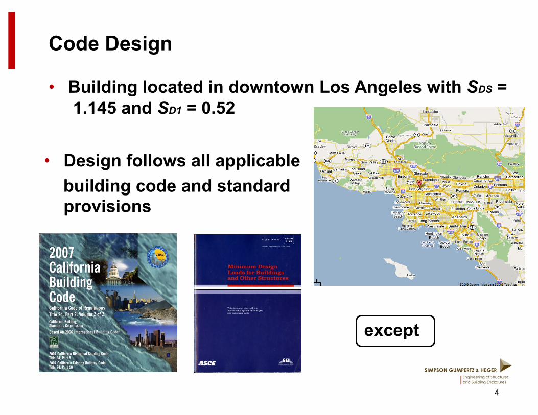
Code Design
• Building located in downtown Los Angeles with SDS = 1.145 and SD1 = 0.52
4
• Design follows all applicable building code and standard
provisions
except

Code Design – Contd.
• Height limitation ignored
5

Code Design
• Gravity framing sized in RAM Structural System
• Lateral Analysis and Design performed in ETABS using 3D response spectrum analysis
6
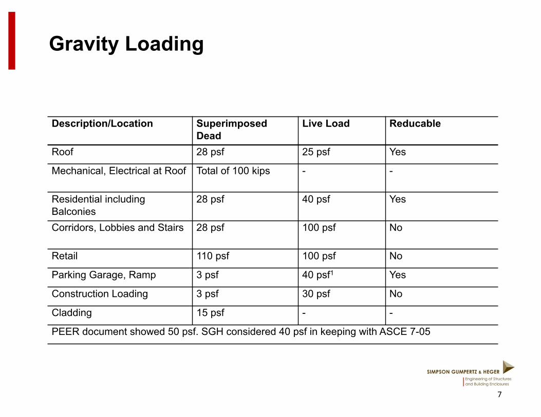
Gravity Loading
7
Description/Location Superimposed Dead
Live Load Reducable
Roof 28 psf 25 psf Yes
Mechanical, Electrical at Roof Total of 100 kips - -
Residential including Balconies
28 psf 40 psf Yes
Corridors, Lobbies and Stairs 28 psf 100 psf No
Retail 110 psf 100 psf No
Parking Garage, Ramp 3 psf 40 psf1 Yes
Construction Loading 3 psf 30 psf No
Cladding 15 psf - -
PEER document showed 50 psf. SGH considered 40 psf in keeping with ASCE 7-05
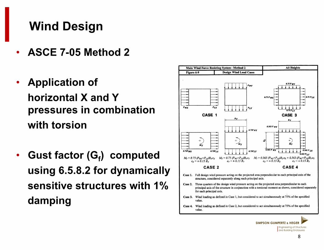
Wind Design
• ASCE 7-05 Method 2
• Application of horizontal X and Y
pressures in combination with torsion
• Gust factor (Gf) computed using 6.5.8.2 for dynamically sensitive structures with 1% damping
8
Wind Design
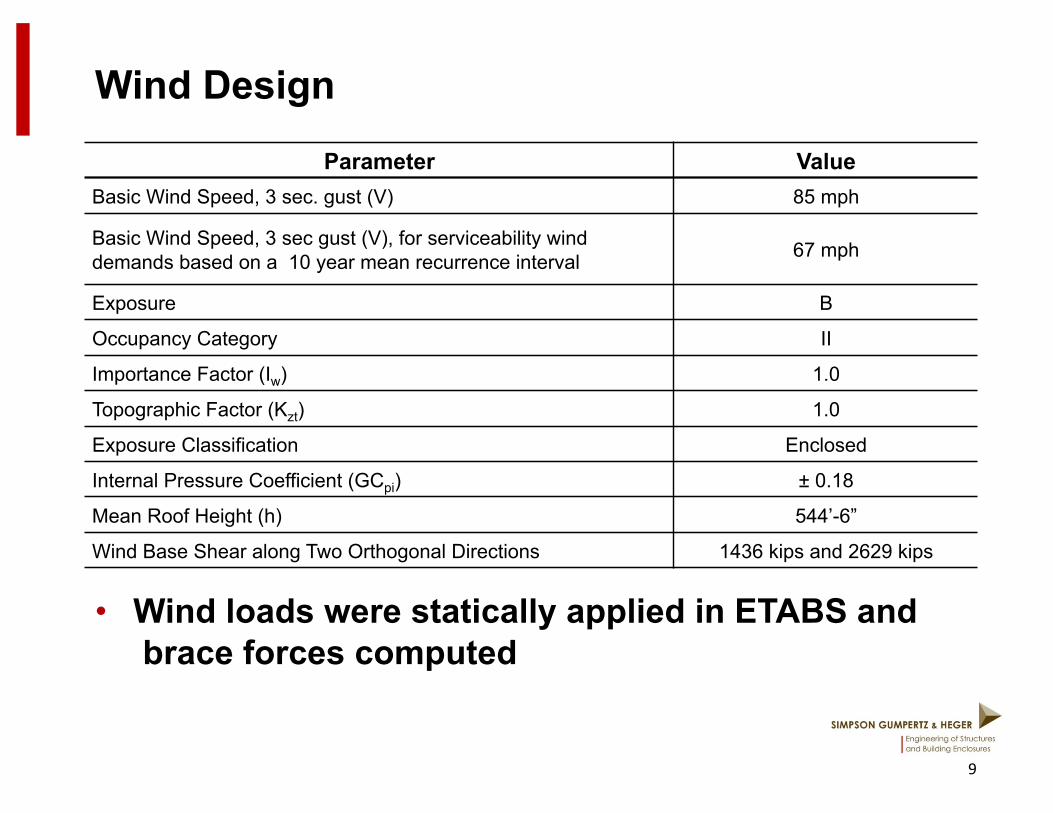
• Wind loads were statically applied in ETABS and brace forces computed
9
Parameter Value Basic Wind Speed, 3 sec. gust (V) 85 mph
Basic Wind Speed, 3 sec gust (V), for serviceability wind demands based on a 10 year mean recurrence interval 67 mph
Exposure B
Occupancy Category II
Importance Factor (Iw) 1.0
Topographic Factor (Kzt) 1.0
Exposure Classification Enclosed
Internal Pressure Coefficient (GCpi) ± 0.18
Mean Roof Height (h) 544’-6”
Wind Base Shear along Two Orthogonal Directions 1436 kips and 2629 kips
Seismic Design
10
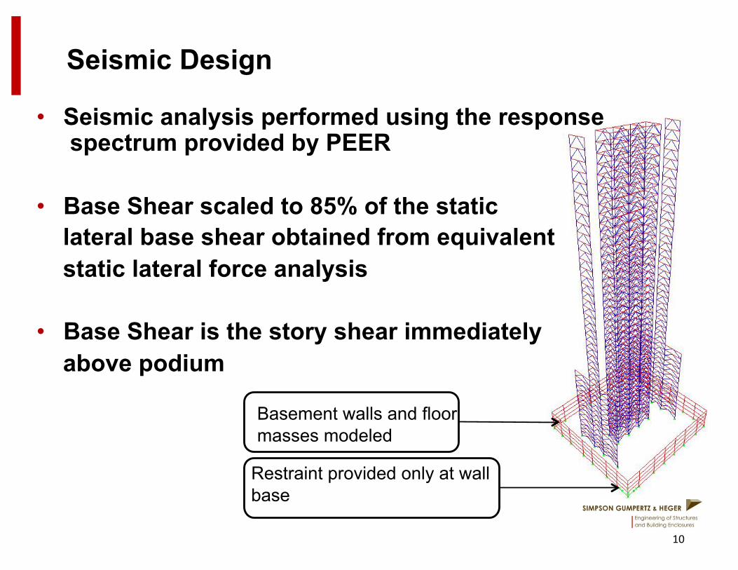
• Seismic analysis performed using the response spectrum provided by PEER
• Base Shear scaled to 85% of the static lateral base shear obtained from equivalent static lateral force analysis
• Base Shear is the story shear immediately above podium
Basement walls and floor masses modeled
Restraint provided only at wall base
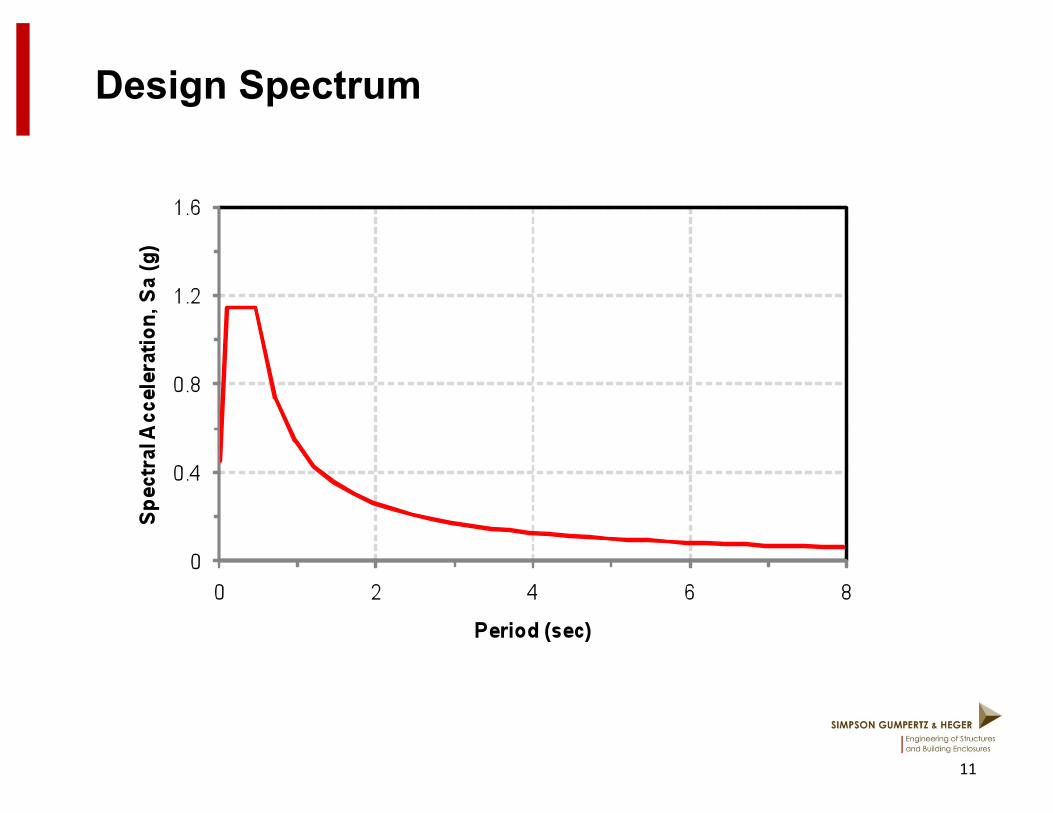
Design Spectrum
11
Seismic Design
12
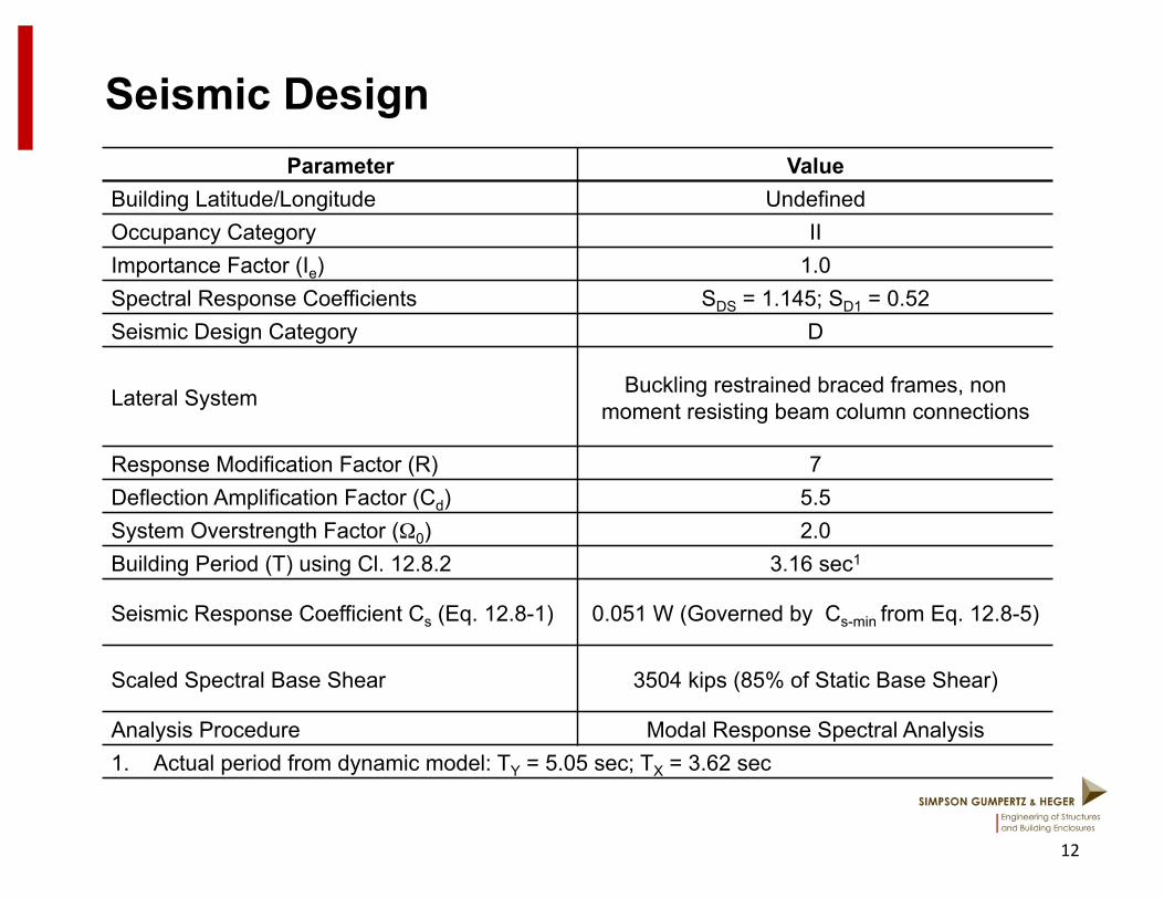
Parameter Value Building Latitude/Longitude Undefined Occupancy Category II Importance Factor (Ie) 1.0 Spectral Response Coefficients SDS = 1.145; SD1 = 0.52 Seismic Design Category D
Lateral System Buckling restrained braced frames, non moment resisting beam column connections
Response Modification Factor (R) 7 Deflection Amplification Factor (Cd) 5.5 System Overstrength Factor (Ω0) 2.0 Building Period (T) using Cl. 12.8.2 3.16 sec1
Seismic Response Coefficient Cs (Eq. 12.8-1) 0.051 W (Governed by Cs-min from Eq. 12.8-5)
Scaled Spectral Base Shear 3504 kips (85% of Static Base Shear)
Analysis Procedure Modal Response Spectral Analysis 1. Actual period from dynamic model: TY = 5.05 sec; TX = 3.62 sec
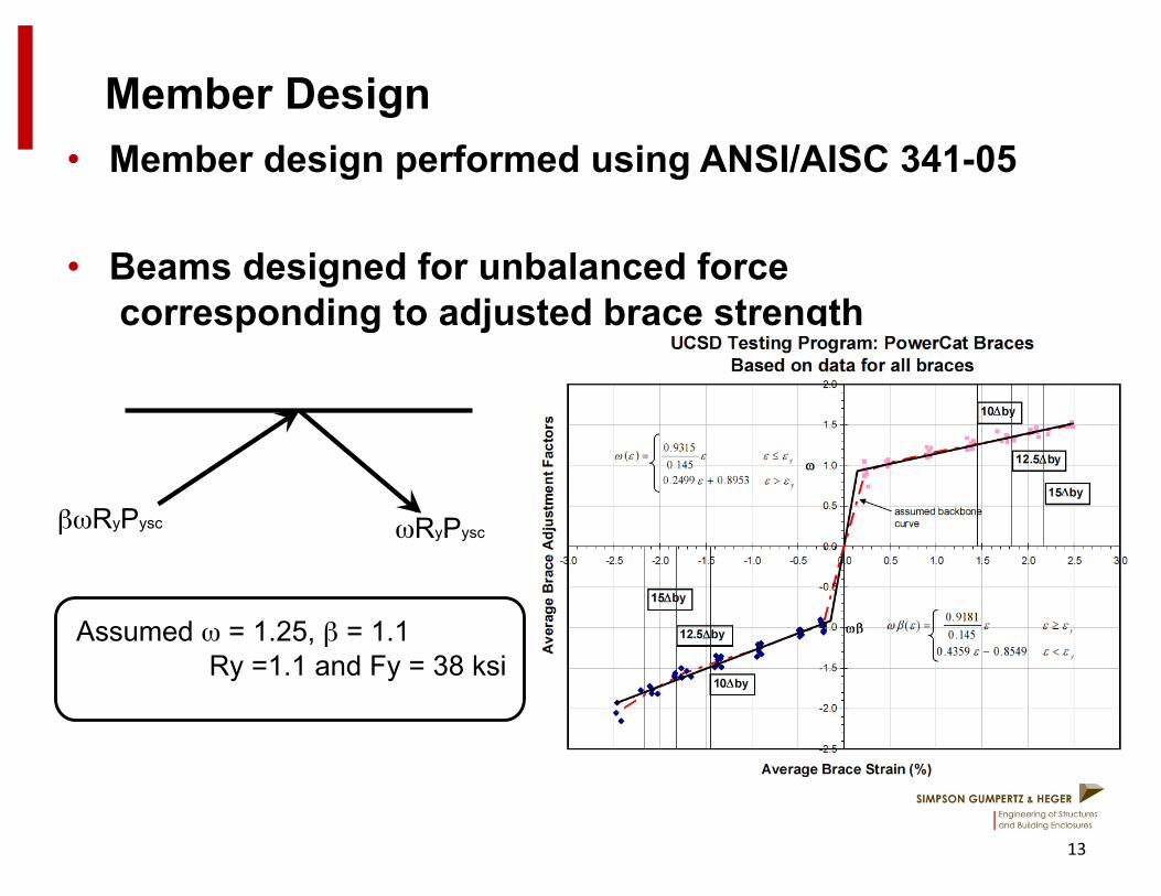
Member Design • Member design performed using ANSI/AISC 341-05
• Beams designed for unbalanced force corresponding to adjusted brace strength
13
βωRyPysc ωRyPysc
Assumed ω = 1.25, β = 1.1 Ry =1.1 and Fy = 38 ksi

Member Design
• Columns designed for accumulated force (sum of vertical components)corresponding to adjusted brace strengths
• Led to large compression and tension design forces for columns and foundations (Note: Attachment of columns to foundations needs to be designed for same forces used for column design)
14
Member Design
15
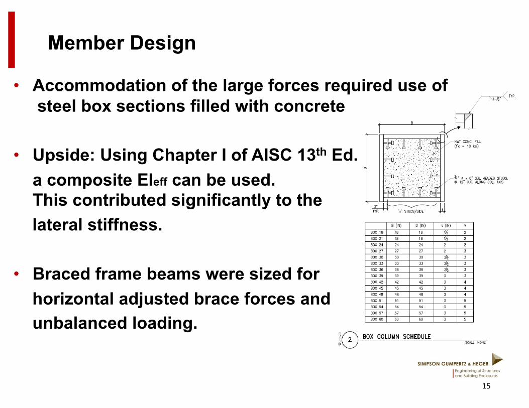
• Accommodation of the large forces required use of steel box sections filled with concrete
• Upside: Using Chapter I of AISC 13th Ed. a composite EIeff can be used. This contributed significantly to the
lateral stiffness.
• Braced frame beams were sized for horizontal adjusted brace forces and unbalanced loading.
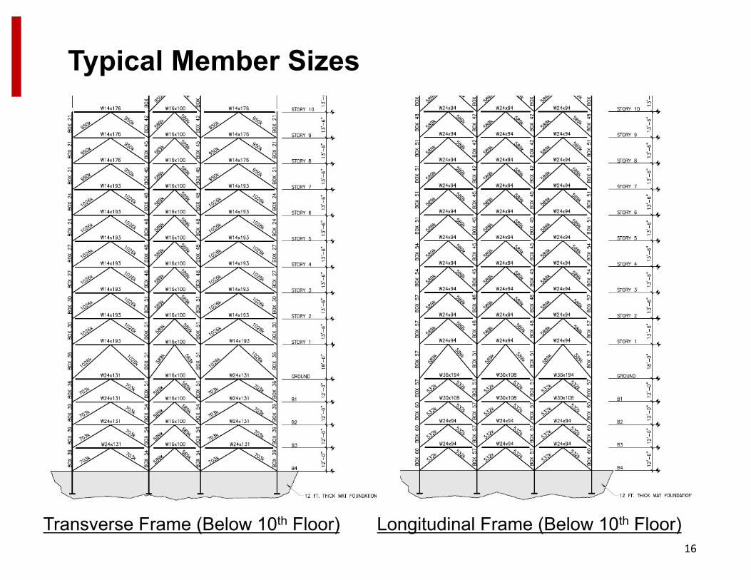
Typical Member Sizes
16
Transverse Frame (Below 10th Floor) Longitudinal Frame (Below 10th Floor)
LATBC-Performance Based Design
17
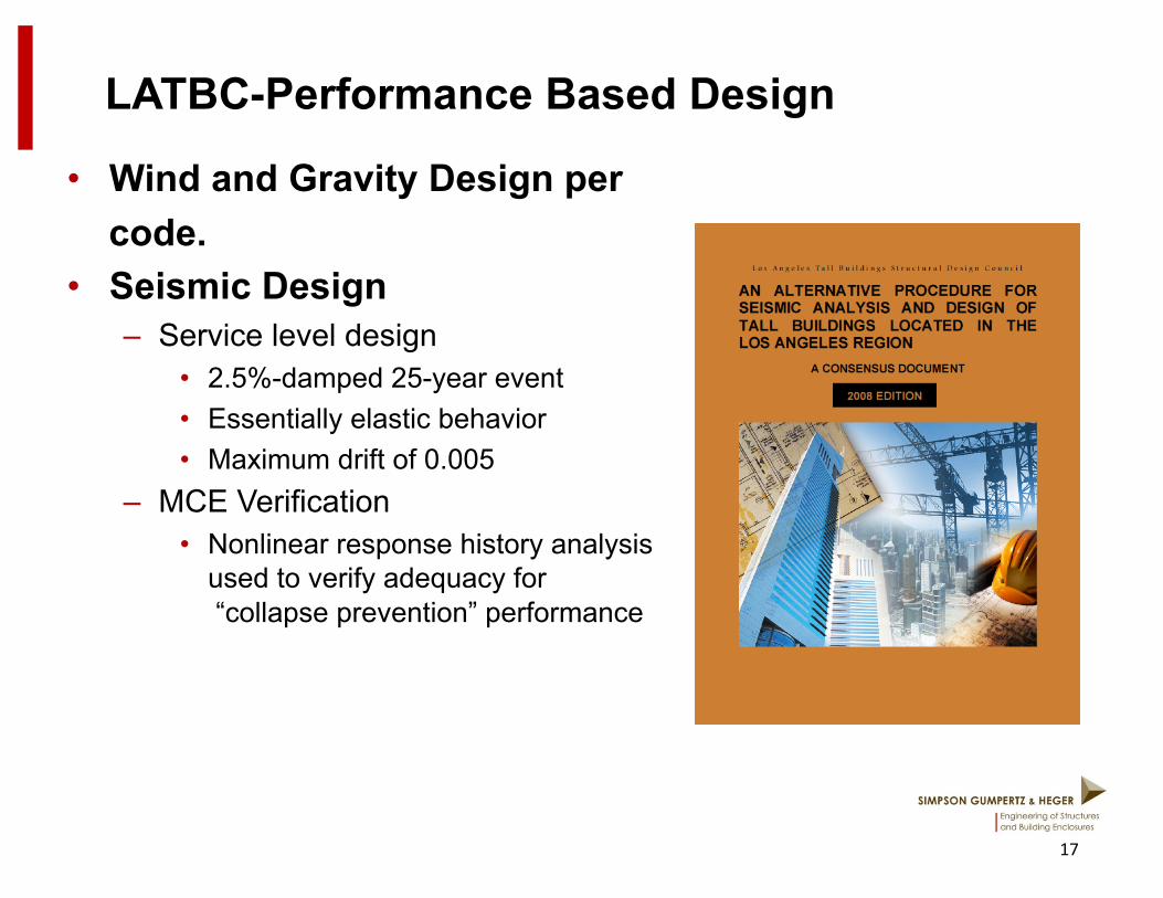
• Wind and Gravity Design per code. • Seismic Design
– Service level design • 2.5%-damped 25-year event • Essentially elastic behavior • Maximum drift of 0.005
– MCE Verification • Nonlinear response history analysis
used to verify adequacy for “collapse prevention” performance
LATBC Design – Service Level
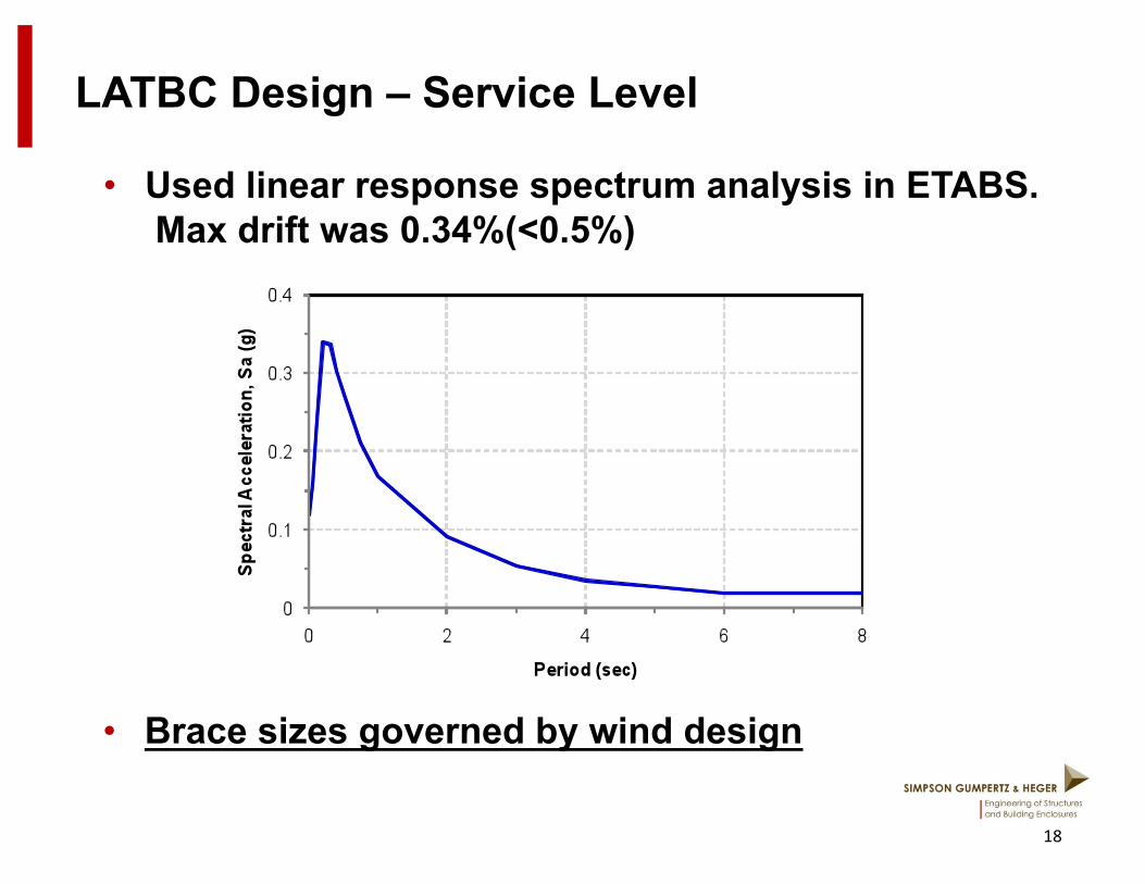
• Used linear response spectrum analysis in ETABS. Max drift was 0.34%(<0.5%)
18
• Brace sizes governed by wind design
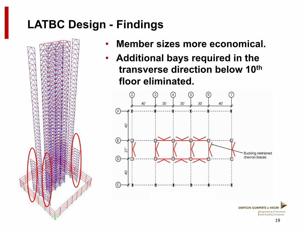
LATBC Design - Findings • Member sizes more economical. • Additional bays required in the
transverse direction below 10th
floor eliminated.
19
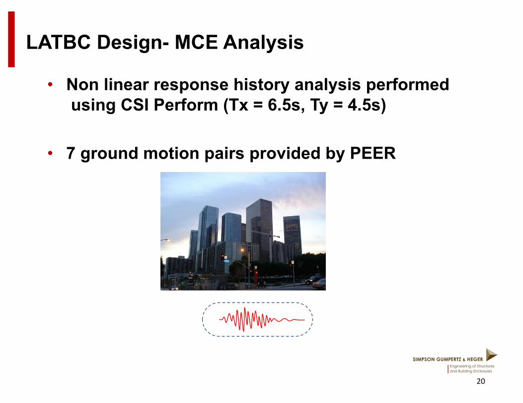
LATBC Design- MCE Analysis
• Non linear response history analysis performed using CSI Perform (Tx = 6.5s, Ty = 4.5s)
• 7 ground motion pairs provided by PEER
20
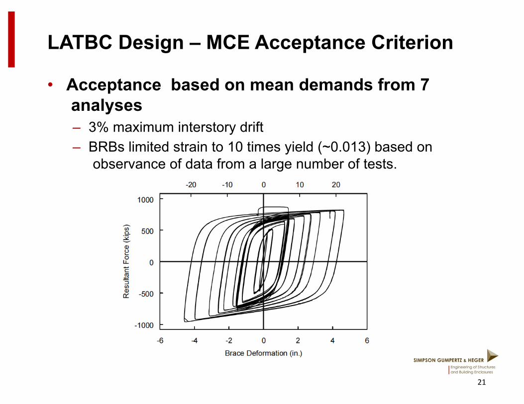
LATBC Design – MCE Acceptance Criterion
• Acceptance based on mean demands from 7 analyses – 3% maximum interstory drift – BRBs limited strain to 10 times yield (~0.013) based on
observance of data from a large number of tests.
21

LATBC Design – MCE Story Drift
22
23
PEER TBI- Performance “+”
• Wind and Gravity Design follow code. • Seismic Design
– Service level – 2.5% damped 43-year spectrum
• Essentially elastic performance • Drift limited to 0.005
– MCE level • Max transient drift <0.03 average
0.045 any single run • Max residual drift < 0.01 average
0.015 any single run • BRB’s respond within range of
acceptable modeling

24
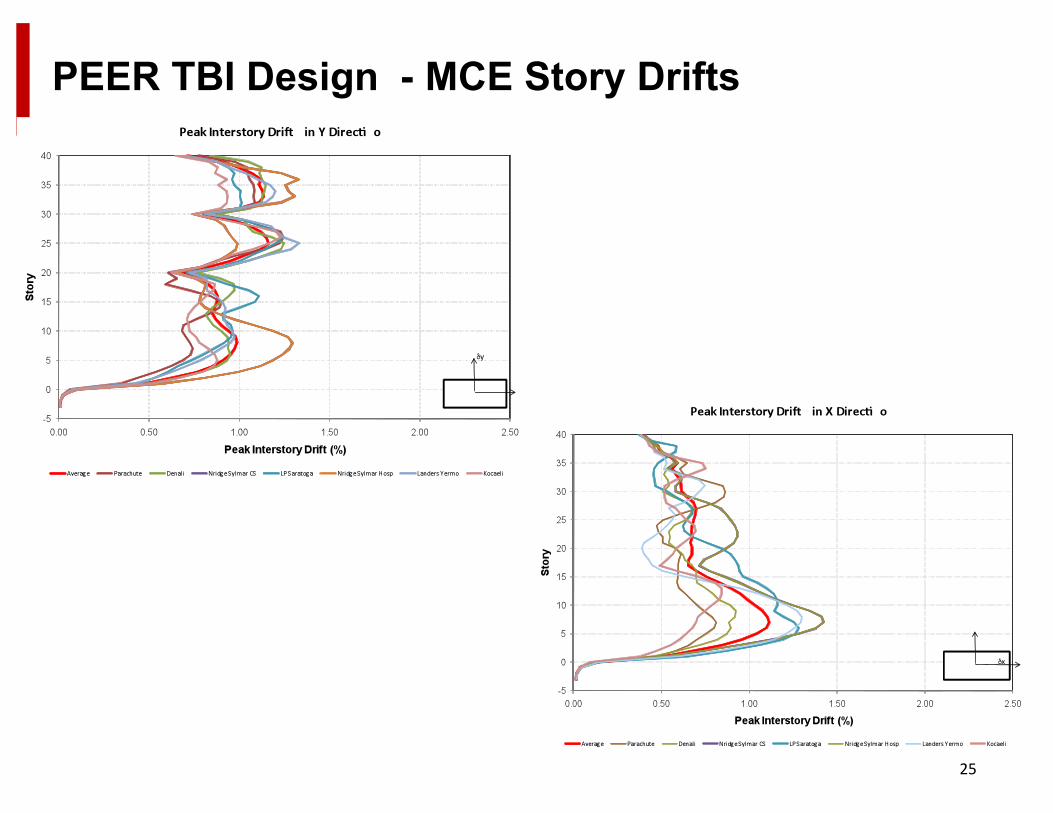
PEER TBI Design
• Started with LATBC design • Drift not satisfied above 30th floor • Addition of outriggers at 40th, 30th and 20th floors to control drift to <0.5% • Upsize some columns & braces
25
PEER TBI Design - MCE Story Drifts
Summary & Conclusions
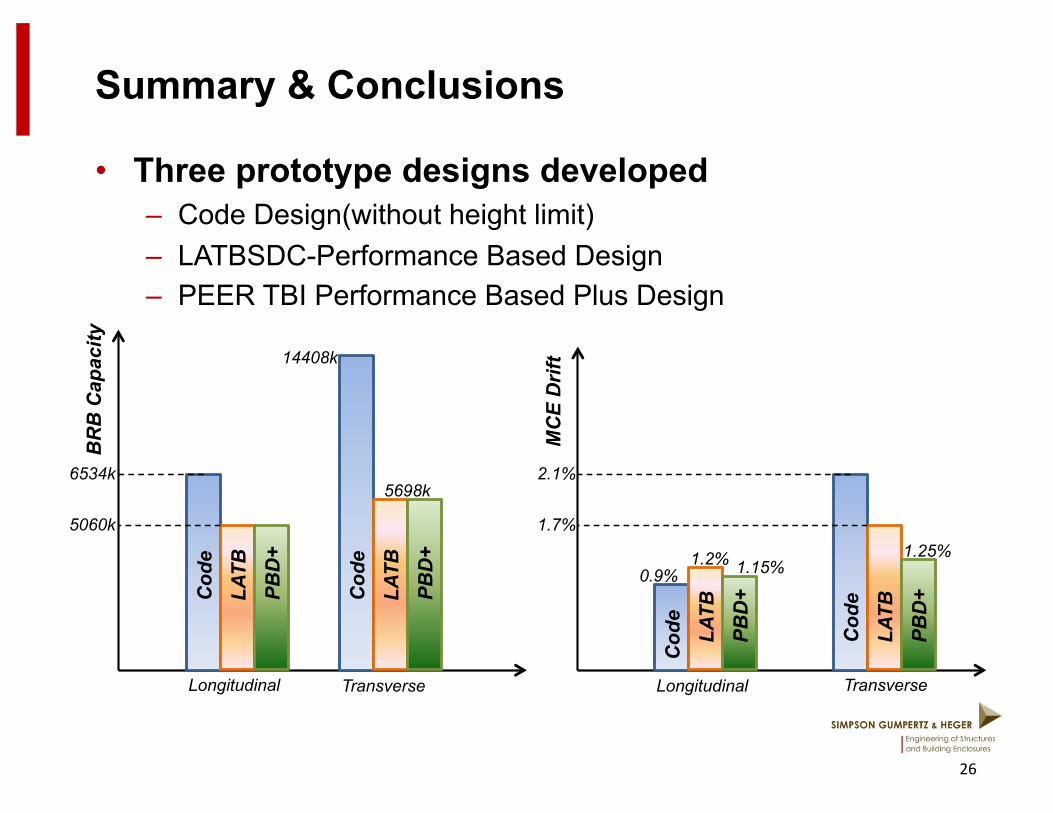
• Three prototype designs developed – Code Design(without height limit) – LATBSDC-Performance Based Design – PEER TBI Performance Based Plus Design
26
Cod
e
PBD
+ LA
TB
6534k
5060k
Cod
e
PBD
+ LA
TB
14408k
5698k
Longitudinal Transverse
BR
B C
apac
ity
Cod
e
PBD
+ LA
TB
2.1%
1.7%
Cod
e
PBD
+ LA
TB 0.9%
Transverse Longitudinal
MC
E D
rift
1.25% 1.2% 1.15%
Summary & Conclusions
• Performance-based Design resulted in more economical member sizes and more practical column base connection
• Building code for BRBs seems to be overly conservative for high rise structures – Assumption that all braces yield simultaneously incorrect
27