Embed Size (px)
Citation preview

IMPORTANT: Please read completely before you begin.
Casement Replacement WindowInstallation Instructions
Installer – Please leave this booklet for thehomeowner after the install is completed.
Part No. 1238676 Item #1012959 Install 245 01/09 © 2009 Weathershield Mfg., Inc.
ii
Casement Replacement Window
START PAGE
Components; General . . . . . . . . . . . . . . . . . . . . . . . . . . . . . . . . . . . . . . . . . . . . . . . . . . . . . . . . . . . . iii
Typical Wood Window Components . . . . . . . . . . . . . . . . . . . . . . . . . . . . . . . . . . . . . . . . . . . . . . . . iv
Safety Alert Symbol; Synthetic Stucco . . . . . . . . . . . . . . . . . . . . . . . . . . . . . . . . . . . . . . . . . . . . . . . v
Sash Removal . . . . . . . . . . . . . . . . . . . . . . . . . . . . . . . . . . . . . . . . . . . . . . . . . . . . . . . . . . . . . . . . . . . 1
Pry Bar, Hammer, Utility Knife, Screwdriver
Opening Preparation . . . . . . . . . . . . . . . . . . . . . . . . . . . . . . . . . . . . . . . . . . . . . . . . . . . . . . . . . . . . . 2
Hammer, Screwdriver, Pry Bar, Fiberglass Insulation, Putty Knife, Level, Tape Measure, Stiff Brush
Window Installation . . . . . . . . . . . . . . . . . . . . . . . . . . . . . . . . . . . . . . . . . . . . . . . . . . . . . . . . . . . . . . 4
Measuring Tape, Hammer, Electric Drill w/Screwdriver Bit, Pry Bar, Shims, Level,
Silicone Sealant, Caulking Gun, Finish Nails, Nail Set, Inside Stops
Apply Optional Aluminum Exterior Trim . . . . . . . . . . . . . . . . . . . . . . . . . . . . . . . . . . . . . . . . . . . . . 9
Measuring Tape, Hacksaw, Silicone Sealant, Caulking Gun, Aluminum Trim Extenders, Tin Snips
Window Operation . . . . . . . . . . . . . . . . . . . . . . . . . . . . . . . . . . . . . . . . . . . . . . . . . . . . . . . . . . . . . . 11
Screen Removal and Reinstall . . . . . . . . . . . . . . . . . . . . . . . . . . . . . . . . . . . . . . . . . . . . . . . . . . . . 12
Sash Removal . . . . . . . . . . . . . . . . . . . . . . . . . . . . . . . . . . . . . . . . . . . . . . . . . . . . . . . . . . . . . . . . . . 13
Sash Reinstall . . . . . . . . . . . . . . . . . . . . . . . . . . . . . . . . . . . . . . . . . . . . . . . . . . . . . . . . . . . . . . . . . . 16
Recommended Finishing Instructions . . . . . . . . . . . . . . . . . . . . . . . . . . . . . . . . . . . . . . . . . . . . . . 18
Painting and Finishing Supplies
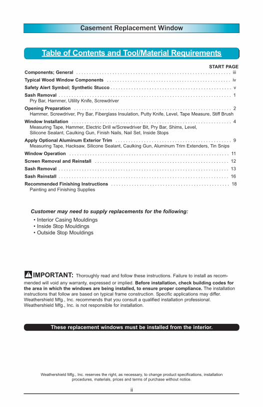
Customer may need to supply replacements for the following:• Interior Casing Mouldings
• Inside Stop Mouldings
• Outside Stop Mouldings
Table of Contents and Tool/Material Requirements
Weathershield Mfg., Inc. reserves the right, as necessary, to change product specifications, installation
procedures, materials, prices and terms of purchase without notice.
IMPORTANT: Thoroughly read and follow these instructions. Failure to install as recom-
mended will void any warranty, expressed or implied. Before installation, check building codes for
the area in which the windows are being installed, to ensure proper compliance. The installation
instructions that follow are based on typical frame construction. Specific applications may differ.
Weathershield Mfg., Inc. recommends that you consult a qualified installation professional.
Weathershield Mfg., Inc. is not responsible for installation.
These replacement windows must be installed from the interior.

iii
Casement Replacement Window
Components
Each Replacement Unit ships with the following standard components:
The sill angle support bracket is provided
with some units. It helps support the win-
dow and fills the gap between the unit’s
sill and the old window sill (FIGURE 1).
Other units may have sills sloped to fit
your specific opening. Sloped sill units do
not require the angle support bracket
(FIGURE 2).
ANGLE
SUPPORT
BRACKET
POSITION TO
ACHIEVE
LEVEL
OLD
SILL
INTERSECTION
OF OLD SILL &
STOOL
STOOLLEVEL at
Level
FIGURE 1 FIGURE 2
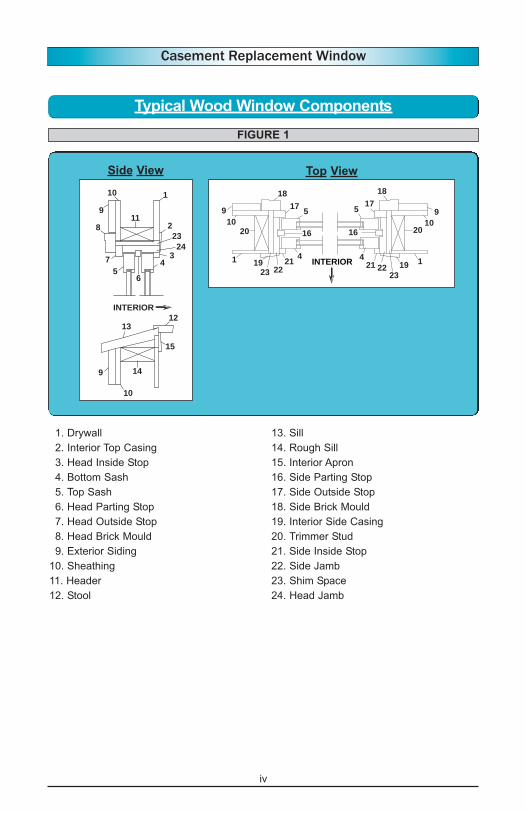
Installing your new Replacement Window
requires removing existing window parts,
test fitting and installing your new unit.
Typical wood window components are
shown on the following page in (FIGURE
1). Refer to this diagram for terms used in
these instructions.
Completely read the installation instructions
before starting any procedure.
IMPORTANT: Wear full protective
clothing including gloves, and safety
glasses.
Optional factory-applied finishes should be
handled with extra care to prevent damage.
General
Qty. Description
1 Window Unit Complete With Sash, Frame and Operating Hardware
32 Installation Shims
8 #8 x 2-1/2" Phillips Bugle Head, Screws
10 Wood Hole Plugs
4 #8 x 1/2" Phillips Pan Head, TEK SS410, Full Thread, Screws
1 Sill Angle Bracket
1 Installation Instruction Booklet
1 Pkg 18' of 1/2" Backer Rod
Optional Contents
1 Set Pre-Cut, Color-Matched Aluminum Trim Extenders
iv
Casement Replacement Window
Typical Wood Window Components
15
10
5
7
9
9
8
4
6
11
14
10
12
1
3
2
23
24
13
INTERIOR
17
18 18
17
20 20
1919
10 10
5 59 9
44
16 16
1 121
2223 232221
INTERIOR
1. Drywall
2. Interior Top Casing
3. Head Inside Stop
4. Bottom Sash
5. Top Sash
6. Head Parting Stop
7. Head Outside Stop
8. Head Brick Mould
9. Exterior Siding
10. Sheathing
11. Header
12. Stool
13. Sill
14. Rough Sill
15. Interior Apron
16. Side Parting Stop
17. Side Outside Stop
18. Side Brick Mould
19. Interior Side Casing
20. Trimmer Stud
21. Side Inside Stop
22. Side Jamb
23. Shim Space
24. Head Jamb
Side View Top View
FIGURE 1

v
Casement Replacement Window
Weight of window and accessories will vary. Use
a reasonable number of people with sufficient
strength to lift, carry and install window unit(s)
and accessories. Always consider site conditions
and use appropriate techniques when installing.
Falling from window opening may result in
serious injury or death. DO NOT leave
openings unattended when children are
present.
Screen will not stop children,
any one or anything from
falling out window.
Keep children and objects
away from open window.
CUT HAZARD
*Non-safety Glass.
*May cause serious
injuries if broken.
*Do not install where
tempered safety glass
is required.
Recognize this symbol. This is the Safety-Alert symbol. When you see this symbol be
alert to the potential for personal injury or product damage.
Safety Alert Symbol
Synthetic Stucco
Serious concerns have been raised about excessive moisture problems in homes and
other buildings that have Exterior Insulation Finish Systems, commonly referred to as EIFS
or Synthetic Stucco.
Many experts agree that a certain amount of water or moisture can be expected to enter
almost any building exterior system. The building system should allow such water and
moisture to escape or “weep” to the exterior, so no damage occurs. However, some EIFS
systems may not allow water or moisture that penetrates the wall system to “weep” to the
exterior. This can cause excessive moisture to accumulate within the wall system, which
can cause serious damage to wall and other building components. It has been reported
that so-called “barrier” EIFS systems are particularly prone to this problem.
Moisture problems in any type of building structure can be reduced by proper design and
construction with appropriate moisture control considerations, taking into account prevail-
ing climate conditions. Examples of moisture control considerations include flashing
and/or sealing of all building exterior penetration points, use of appropriate materials and
construction techniques, adherence to applicable building codes, and general attention to
proper design and workmanship of the entire building system, including allowances for
management of moisture within the wall system.
Determination of proper building design, components and construction, including moisture
management, are the responsibility of the design architect, the contractors, and the manu-
facturer of the exterior wall finish products. Questions and concerns about moisture man-
agement issues should be taken up with these professionals. The window manufacturer is
not responsible for problems or damages caused by deficiencies in building design, con-
struction or maintenance, failure to install our products properly, or use of our products in
systems that do not allow for proper management of moisture within the wall system.

1
Casement Replacement Window
Sash Removal
1. Unlock and raise bottom sash. Prop
sash open with a block of wood.
2. Use a pry bar or stiff putty knife to pry
side (FIGURE 1) and head (FIGURE 2)
inside stop mouldings away from jambs.
Handle carefully as these mouldings canbe reused.
Move sash slowly and
carefully to prevent glass
from shattering. Wear full protective
clothing including gloves and safety
glasses.
3. Lower bottom sash and prop it up so its
bottom edge rests above the stool (Item
12, FIGURE 1, Page iv).
4. Rotate one side of bottom sash inward
(FIGURE 3). Cut sash cord.
5. Work sash toward interior and remove
cord from opposite side.
6. Safely discard bottom sash.
NOTE: If top sash is stationary, remove the
support blocks at the bottom of the
top sash. If sash is “painted-in”,
insert a putty knife between sash
and the side and head parting stops.
Work knife around all sides to break
paint seal.
7. Lower the top sash and prop its bottom
edge slightly above the stool.
8. Use a pry bar or stiff putty knife to pry
side parting stops (FIGURE 4) and head
parting stop (FIGURE 5) away from side
and head jambs. Remove all pieces. The
parting stops will not be reused.
9. Rotate one side of sash inward. Cut
sash cord (FIGURE 6).
10. Work sash toward interior and remove
cord from opposite side.
11. Safely discard top sash.
CUT
SASH
CORD
INTERIOR
FIGURE 1
INTERIOR
FIGURE 2
FIGURE 3
INTERIOR
INTERIOR
FIGURE 5
FIGURE 4
CUT
SASH
CORD
FIGURE 6
Improper use of hand and power tools could
result in personal injury and/or product damage.
Follow equipment manufacturers’ instructions for
safe operation. Always wear safety glasses.

2
Casement Replacement Window
1. Cut sash cords and remove sash weights
from both side jambs (FIGURE 1).
2. Remove screws and pry out sash rope
pulleys (FIGURE 2).
3. Remove sash ropes.
4. Install fiberglass insulation in the sash
weight and pulley rope cavities (FIGURE
3). Do not over pack insulation.5. Examine opening. Remove any objects
that would interfere with new window’s fit.
6. Clean all loose dirt and paint from
opening.
FIGURE 1
FIGURE 2
FIGURE 3
Opening Preparation

3
Casement Replacement Window
Opening Preparation (cont.)
FIGURE 4
OUTSIDE
OF HOME
HEIGHT
FIGURE 5
WIDTH JAMB TO JAMB
OUTSIDE OF HOME
VIEWED FROM THE TOP
FIGURE 7
OPENING WIDTH1/4"
FRAME WIDTH
FR
AM
E H
EIG
HT
OP
EN
ING
HE
IGH
T
1/4"
FIGURE 6
FIGURE 8
7. Check opening for the following:
• Rotted components
• Missing or broken stops
Fix any of these conditions before pro-
ceeding.
8. Check opening for level, plumb, and
square (FIGURE 4). Use a level to
check the sill, head and side jambs.
Measure the opening diagonally from
corner to corner to check for square.
Measure ments must be within 1/4" of
each other. Fix any of these conditions
before proceeding.
9. Measure the height (FIGURE 5) and
width (FIGURE 7) of the opening. Do notinclude the outside stops. Compare these
measurements to the height (FIGURE 6)
and frame width (FIGURE 8) of the new
window.
The replacement window must be ableto fit in the opening and be held fromfalling through by the outside stops onthe sides and head.
Make necessary adjustments to the open-
ing so this support is provided to the new
window.
IMPORTANT: The outside stops
(blind stops) cannot exceed 1/2" in depth
from the outer edge of the stop to the old
window frame (FIGURE 9). Check stops
around entire opening making adjust-
ments to reach the 1/2" maximum depth.
Max.
OUTSIDE
STOP
OLD
WINDOW
FRAME
½"
FIGURE 9

4
Casement Replacement Window
Window Installation
Check Replacement Window Fit
NOTE: Remove all packing. Make sure sash
is fully seated in frame and locked.
Clean all loose material and dirt from
opening. Remove any objects that
would damage new unit or interfere
with proper fit and sash operation.
1. Insert new window unit into opening to
check fit (FIGURE 1). Unit must fit within
the side and head outside stops (FIGURE
2) and sit flush against the stop’s face.
It may be necessary to chisel a relief area
at the bottom of the side outside stops to
provide space for the unit to rotate into a
vertical position (FIGURE 3).
Remove window unit after checking fit.
Make adjustments to the opening/stops to
obtain a good fit. A shim space is needed
on sides and top; none required at the sill.
FIGURE 1
FIGURE 2
OUTSIDE
STOP
STOOL
NEW WINDOW
FITS TIGHT &
FLUSH AGAINST
THIS FACE.
INTERIOR
SIDE
OUTSIDE
STOP
CHISEL OUT
RELIEF FOR
UNIT
FIGURE 3

5
Casement Replacement Window
Window Installation (cont.)
FIGURE 6
Prepare The Opening
1. Measure inside width of the opening
between the side outside stops (FIGURE
4). Cut the aluminum angle support brack-
et to this length.
2. Using a level and the angle support brack-
et, find the location on the old sill that will
provide a level plane between the inter-
section of the stool and old sill and the top
of the angle support bracket (FIGURE 5).
Mark this location across the sill’s width.
3. If attachment holes are not pre-drilled in
the angle support bracket, hold bracket at
the level location and pre-drill holes for the
attachment screws. Space holes evenly
along length of angle support bracket.
If bracket is pre-drilled, skip to Step 4.
4. Attach bracket securely to the old sill using
the included #8 x 1/2" Phillips pan head,
screws (FIGURE 6).
MEASURE HERE
OUTSIDE OF HOME
VIEWED FROM THE TOP
FIGURE 4
FIGURE 5
ANGLE
SUPPORT
BRACKET
POSITION TO
ACHIEVE
LEVEL
OLD
SILL
INTERSECTION
OF OLD SILL &
STOOL
STOOLLEVEL at
Level
6
Casement Replacement Window
Window Installation (cont.)
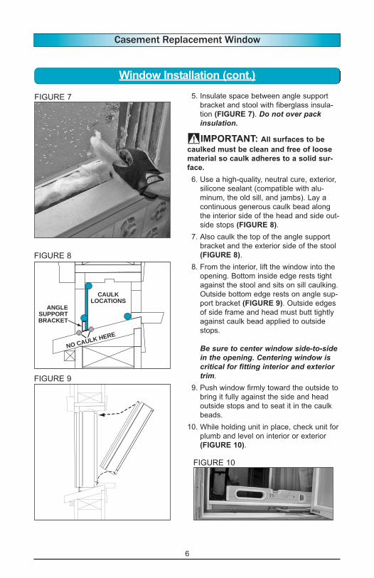
5. Insulate space between angle support
bracket and stool with fiberglass insula-
tion (FIGURE 7). Do not over packinsulation.
IMPORTANT: All surfaces to be
caulked must be clean and free of loose
material so caulk adheres to a solid sur-
face.
6. Use a high-quality, neutral cure, exterior,
silicone sealant (compatible with alu-
minum, the old sill, and jambs). Lay a
continuous generous caulk bead along
the interior side of the head and side out-
side stops (FIGURE 8).
7. Also caulk the top of the angle support
bracket and the exterior side of the stool
(FIGURE 8).
8. From the interior, lift the window into the
opening. Bottom inside edge rests tight
against the stool and sits on sill caulking.
Outside bottom edge rests on angle sup-
port bracket (FIGURE 9). Outside edges
of side frame and head must butt tightly
against caulk bead applied to outside
stops.
Be sure to center window side-to-sidein the opening. Centering window iscritical for fitting interior and exteriortrim.
9. Push window firmly toward the outside to
bring it fully against the side and head
outside stops and to seat it in the caulk
beads.
10. While holding unit in place, check unit for
plumb and level on interior or exterior
(FIGURE 10).
FIGURE 9
FIGURE 7
FIGURE 8
CAULK
LOCATIONS
NO CAULK HERE
ANGLE
SUPPORT
BRACKET
FIGURE 10
7
Casement Replacement Window
Window Installation (cont.)
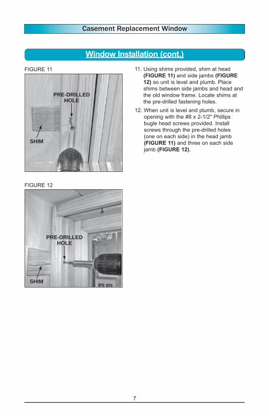
11. Using shims provided, shim at head
(FIGURE 11) and side jambs (FIGURE
12) so unit is level and plumb. Place
shims between side jambs and head and
the old window frame. Locate shims at
the pre-drilled fastening holes.
12. When unit is level and plumb, secure in
opening with the #8 x 2-1/2" Phillips
bugle head screws provided. Install
screws through the pre-drilled holes
(one on each side) in the head jamb
(FIGURE 11) and three on each side
jamb (FIGURE 12).
PRE-DRILLED
HOLE
SHIM
PRE-DRILLED
HOLE
SHIM
FIGURE 11
FIGURE 12
8
Casement Replacement Window
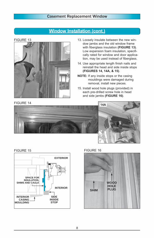
13. Loosely insulate between the new win-
dow jambs and the old window frame
with fiberglass insulation (FIGURE 13).
Low expansion foam insulation, specifi-
cally rated for window and door applica-
tion, may be used instead of fiberglass.
14. Use appropriate length finish nails and
reinstall the head and side inside stops
(FIGURES 14, 14A, & 15).
NOTE: If any inside stops or the casing
mouldings were damaged during
removal, install new pieces.
15. Install wood hole plugs (provided) in
each pre-drilled screw hole in head
and side jambs (FIGURE 16).
FIGURE 13
FIGURE 15
EXTERIOR
INTERIOR
SPACE FOR
INSULATION,
SHIMS AND CAULK
SIDE
INSIDE
STOP
INTERIOR
CASING
MOULDING
Window Installation (cont.)
FIGURE 14
FIGURE 16
WOOD
HOLE
PLUGSHIM
14A

9
Casement Replacement Window
Gaps (FIGURE 1) between the window, and
the siding or brickmould can be covered with
optional color-matched aluminum trim.
Aluminum trim will be factory pre-cut to
nominal length. Each piece will be too long
so it can be adjusted to fit each window
opening.
Trim will be notched at the ends (FIGURE 2)
so it can run past the window cladding and
reach out to the existing siding or casing
mouldings.
The head piece must be applied with
a notch at each end. The side pieces
are cut flat at the top and notched at
the bottom. The sill piece is cut flat on
both ends.
(FIGURE 3) shows the length meas-
uring locations.
Trim width is determined by distance
measured from the exterior accessory
groove to the existing casing mould-
ing or siding and the sill. The X in
(FIGURE 4) shows a typical width
measurement.
EXTERIORX
FIGURE 4
GAPS TO COVER
FIGURE 1
FIGURE 3
Optional Exterior Trim Application
HEAD PIECE LENGTH
ME
AS
UR
E S
IDE
PIE
CE
FR
OM
BO
TT
OM
OF
HE
AD
TR
IM T
O S
ILL
MEASURE SILL PIECE FROM
SIDE PIECE TO SIDE PIECE
FIGURE 2
10
Casement Replacement Window
Optional Exterior Trim Application (cont.)
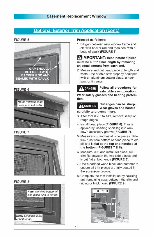
FIGURE 5
GAP SHOULD
BE FILLED WITH
BACKER ROD AND
SEALED WITH CAULK
CAULK
Note: Notched bottom ofside piece runs to old sill.
Note: Sill piece is flatat both ends.
Proceed as follows:
1. Fill gap between new window frame and
old with backer rod and then seal with a
bead of caulk (FIGURE 5).
IMPORTANT: Head notched piece
must be cut to final length by removing
an equal amount from each end.
2. Measure and cut head piece to length and
width. Use a table saw properly equipped
with an aluminum cutting blade, a hack
saw, or tin snips.
Follow all procedures for
safe table saw operation.
Wear safety glasses and hearing protec-
tion.
Cut edges can be sharp.
Wear gloves and handle
carefully to prevent injury.
3. After trim is cut to size, remove sharp or
rough edges.
4. Install head piece (FIGURE 6). Trim is
applied by inserting short leg into win-
dow’s accessory groove (FIGURE 7).
5. Measure, cut and install side pieces. Side
trim runs from bottom of head piece to old
sill and is flat at the top and notched at
the bottom (FIGURES 7 & 8).
6. Measure, cut, and install sill piece. Sill
trim fits between the two side pieces and
is cut flat at both ends (FIGURE 8).
7. Use a padded wood block and hammer to
ensure all trim pieces are fully seated in
the accessory groove.
8. Complete the trim installation by caulking
any remaining gaps between the trim and
siding or brickmould (FIGURE 9).
FIGURE 6
Note: Notched headpiece runs full width.
FIGURE 8
FIGURE 7
FIGURE 9

11
Casement Replacement Window
Window Operation
1. Sash is locked when lock lever is pulled
down against the stop (FIGURE 1).
2. Sash is unlocked when lock lever is lifted
all the way up.
NOTE: Following instructions are for a left-
hinged casement (as viewed from the
outside).
While standing inside and facing window –
3. To open sash move lock lever to unlock
position, turn crank handle in a counter-
clockwise direction (FIGURE 2).
4. To close sash turn crank handle clockwise
until sash is fully shut. Lock window by
moving lock lever fully downward.
NOTE: A right-hinged casement (as viewed
from the outside) would function
opposite – to open – turn handle
counterclockwise to close – turn han-
dle clockwise.
NOTE: A single-arm operator unit’s crank
handle functions opposite of the
above descriptions.
CL
O
SE
OPEN
LOCKED
UNLOCKED
FIGURE 1
FIGURE 2
12
Casement Replacement Window
Screen Removal and Reinstall
Screen Removal
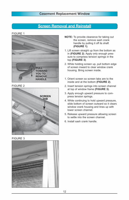
NOTE: To provide clearance for taking out
the screen, remove sash crank
handle by pulling it off its shaft
(FIGURE 1).
1. Lift screen straight up from the bottom as
in (FIGURE 2). Apply only enough pres-
sure to compress tension springs in the
top (FIGURE 3).
2. While holding screen up, pull bottom edge
of screen inward to clear window crank
housing. Bring screen inside.
Screen Reinstall
1. Orient screen so screen tabs are to the
inside and at the bottom (FIGURE 2).
2. Insert tension springs into screen channel
at top of window frame (FIGURE 3).
3. Apply enough upward pressure to com-
press tension springs.
4. While continuing to hold upward pressure,
slide bottom of screen outward so it clears
window crank housing and lines up with
lower screen channel.
5. Release upward pressure allowing screen
to settle into the screen channel.
6. Install sash crank handle.
FIGURE 2
SCREEN
TAB
FIGURE 3
PULL
TOWARD
YOU TO
REMOVE
HANDLE
FIGURE 1
13
Casement Replacement Window
Sash Removal
Sash Removal
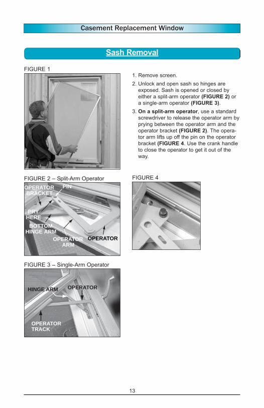
1. Remove screen.
2. Unlock and open sash so hinges are
exposed. Sash is opened or closed by
either a split-arm operator (FIGURE 2) or
a single-arm operator (FIGURE 3).
3. On a split-arm operator, use a standard
screwdriver to release the operator arm by
prying between the operator arm and the
operator bracket (FIGURE 2). The opera-
tor arm lifts up off the pin on the operator
bracket (FIGURE 4. Use the crank handle
to close the operator to get it out of the
way.
FIGURE 1
OPERATOR
BRACKET
PIN
OPERATOR
ARM
BOTTOM
HINGE ARM
OPERATOR
PRY
HERE
FIGURE 2 – Split-Arm Operator FIGURE 4
OPERATORHINGE ARM
OPERATOR
TRACK
FIGURE 3 – Single-Arm Operator
14
Casement Replacement Window
Sash Removal (Cont.)
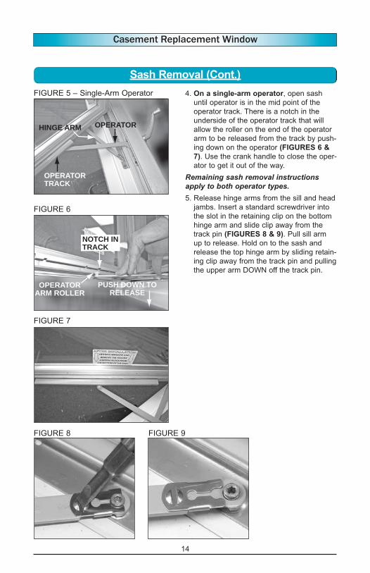
4. On a single-arm operator, open sash
until operator is in the mid point of the
operator track. There is a notch in the
underside of the operator track that will
allow the roller on the end of the operator
arm to be released from the track by push-
ing down on the operator (FIGURES 6 &
7). Use the crank handle to close the oper-
ator to get it out of the way.
Remaining sash removal instructionsapply to both operator types.5. Release hinge arms from the sill and head
jambs. Insert a standard screwdriver into
the slot in the retaining clip on the bottom
hinge arm and slide clip away from the
track pin (FIGURES 8 & 9). Pull sill arm
up to release. Hold on to the sash and
release the top hinge arm by sliding retain-
ing clip away from the track pin and pulling
the upper arm DOWN off the track pin.
FIGURE 6
NOTCH IN
TRACK
OPERATOR
ARM ROLLER
PUSH DOWN TO
RELEASE
FIGURE 7
FIGURE 8 FIGURE 9
OPERATORHINGE ARM
OPERATOR
TRACK
FIGURE 5 – Single-Arm Operator

15
Casement Replacement Window
Sash Removal (Cont.)
6. With both upper and lower hinge arms and
lower operator arm released, carefully
slide the sash along the hinge track
toward the center of the window until
the hinge shoes are free of the tracks
(FIGURES 10 & 10A).
7. The sash is now released, and can be
turned and brought into the building
(FIGURE 11).
SLIDE SASH
TOWARD
CENTER OF
WINDOW
HINGE
TRACK
HINGE
SHOE
HINGE
SHOE
HINGE TRACK
SLIDE TO
REMOVE
10AFIGURE 10
FIGURE 11

16
Casement Replacement Window
Sash Reinstall
The following instructions apply to bothoperator types.1. Orient sash so operator bracket is to the
inside, at the bottom, and closest to the
side jamb. Carefully lift sash through open-
ing. Rest the bottom hinge shoe near the
hinge track pin (FIGURE 1). Start the top
hinge shoe into the top hinge track (FIG-
URE 2). Start the bottom shoe into the bot-
tom hinge track (FIGURE 3). Slide the
sash toward the side jamb so both hinge
shoes slide along with the sash.
2. Place hole in the top hinge arm under the
top track pin. Push up to seat arm on pin.
Place a standard screwdriver into the slot
on the retaining clip and slide toward track
pin until it snaps into place.
3. Place hole in the bottom hinge arm on top
of the bottom track pin (FIGURE 4). Push
down to seat arm on pin. Place a screw-
driver into the slot on the retaining clip and
slide toward track pin until it snaps into
place (FIGURE 5). Test top and bottom
arms to make sure they are securely
attached to their respective track pins.
Leave window partly open for the nextsteps.
FIGURE 2
FIGURE 3
FIGURE 1
HINGE
SHOE
HINGE
TRACK
SLIDE TO INSTALL
HINGE
TRACKHINGE
SHOE
SLIDE TO INSTALL
SLIDE SASH
TOWARD
SIDE JAMB
HINGE
TRACK
HINGE
SHOETRACK
PINOPERATOR
BRACKET
FIGURE 4 FIGURE 5

17
Casement Replacement Window
Sash Reinstall (Cont.)
4. For the split-arm operator, use the crank
handle to open the operator. Align the
operator arm above the pin on the opera-
tor bracket. Push down on the operator
arm to snap the arm onto the pin (FIGURE
6). Once the top and bottom hinge arms
and the bottom operator arm are secured,
the sash can be closed and locked.
5. For the single-arm operator, use the
crank handle to open the operator. Align
the roller at the end of the operator arm
with the arrow embossed on the top of the
operator track at the track’s midpoint. This
arrow will help align the roller with the
notch in the underside of the track
(FIGURE 7). Use the crank handle or
manually adjust sash position to line up
notch. Once notch and roller are aligned
push down slightly on operator arm and
slip roller under the track. Then lift
up on arm to seat roller into guides on
track (FIGURE 8).
Once the top and bottom hinge arms and
the bottom operator arm are secured, the
sash can be closed and locked.
6. Reinstall screen.
FIGURE 6
NOTCH IN
OPERATOR
TRACK
ROLLER ON
OPERATOR
ARM
VIEWED FROM UNDERSIDE OF SASH
FIGURE 7
FIGURE 8

18
Casement Replacement Window
Always follow chemical manufacturers’ safety instructions when using chemicals to avoid
injury or illness.
Recommended Finishing Instructions
Vinyl and aluminum may be cleaned with
mild soap and water. Hard to remove
stains and mineral deposits may be
removed with mineral spirits. Factory-
applied painted surfaces can be cleaned
with mild household detergents and water.
• Do NOT clean any surface with gasoline,
diesel fuel, solvent based, or petrole-
um based products.
• Do NOT use abrasive materials or
strong acidic solutions against vinyl,
aluminum, glass, or factory-applied
finishes.
• Do NOT scrape or use tools that might
damage the surface.
• Do NOT paint vinyl or aluminum sur-
faces.
• Do NOT use mastic-type tapes such as
Duct Tape®.
NOTE: If masking tape is used on any
surface to aid in painting or stain-
ing, remove tape as soon as pos-
sible after use. Tape must be
removed within 24 hours of appli-
cation.
For long term use, such as stucco applica-
tions; use tape that will release, even
when exposed to high temperatures for an
extended period of time. (Examples
include 3M #2080 and #2090 tapes.)
For Bare Wood Surfaces
For best results, wood should be sealed
immediately upon installation or upon
receipt, especially if unit is being stored
for ANY length of time.
1. Remove all construction and adhesive
label residue with mineral spirits before
finishing.
2. Lightly sand surfaces being finished
with 180 grit or finer sandpaper. Be
careful not to scratch the glass.
3. After sanding, clean-off sanding dust
using lacquer thinner applied to a cloth
so the cloth is slightly damp. Let sur-
face dry completely.
-If a painted surface is desired:
• If a wood unit is delivered with factory-
applied primer paint, it may be painted
without repriming, providing the finish
paint coat is applied within six (6)
months of unit installation.
• If a factory-primed wood unit requires
repriming contact your customer service
representative for help in selecting a
primer compatible with the factory
applied material.
• Factory-applied AccentialsTM color sys-
tem finishes in standard, designer or
custom colors do not require additional
painting. For “touch up” paint specifica-
tions contact your customer service rep-
resentative.
1. An unprimed wood unit requires prim-
ing. Use only oil-based primer. Use
compatible oil or water-based finish
coats. Refer to the primer and paint
manufacturers’ instructions.
2. When priming bare wood or repriming,
cover all exposed wood surfaces.
Priming all exposed surfaces helps pre-
vent end splitting, warping and/or
checking.
3. Once primed, apply two (2) coats of
paint (again on all exposed sides) to
each item.
Continued on next page.
19
Casement Replacement Window
Recommended Finishing Instructions (cont.)
-If a stained surface is desired:
If no sealer is applied over
stain, the wood will weath-
er very rapidly and defects will occur.
Apply at least two (2) coats of sealer.
1. Use only oil-based stain. A gel stain is
easier to apply as it does not easily run
or drip. The clear top coats may be oil
or water-based. Apply at least two top
coats of sealer or varnish.
• A pre-stain wood conditioner, applied
before staining, will help softer woods
like pine absorb stain more evenly. Apply
both wood conditioner and desired stain
according to the manufacturers’ instruc-
tions.
2. Apply one (1) coat of sealer to the
stained surface and let dry. Using a
spar (marine) varnish as a sealer pro-
vides extra protection against sunlight
and moisture. Let sealer dry completely.
3. Before applying the next finish coat,
make sure the previous coat is com-
pletely dry. Then lightly sand previous
finish coat with 180 grit or finer sandpa-
per. Clean off all sanding dust and wipe
surfaces with a tack cloth.
4. Apply next coat of desired finish to sur-
face and let dry. Apply only one coat at
a time.
5. For any additional coats of finish,
repeat steps 3 and 4.
-For a clear (natural) finish: Follow Steps
1, 2, and 3 under “Bare Wood” and Steps
2, 3, 4, and 5 under “stained surface”.
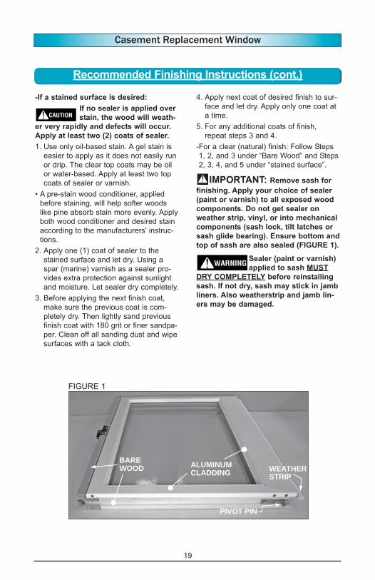
IMPORTANT: Remove sash for
finishing. Apply your choice of sealer
(paint or varnish) to all exposed wood
components. Do not get sealer on
weather strip, vinyl, or into mechanical
components (sash lock, tilt latches or
sash glide bearing). Ensure bottom and
top of sash are also sealed (FIGURE 1).
Sealer (paint or varnish)
applied to sash MUST
DRY COMPLETELY before reinstalling
sash. If not dry, sash may stick in jamb
liners. Also weatherstrip and jamb lin-
ers may be damaged.
ALUMINUM
CLADDING
BARE
WOOD WEATHER
STRIP
PIVOT PIN
FIGURE 1