Embed Size (px)
Citation preview
Casing MaterialsSelection &CorrosionGuidelines
BP Amoco report no. BPA-D-003dated September 1999
Main CDContents
J W Martin
September 1999 Issue 2Section C15 Material Selection and Corrosion Guidelines 15-17
BP AmocoCasing Design Manual BPA-D-003
Page
15.1 Scope 15-1
15.2 Material Selection Process 15-215.2.1 Casing Exposed to Muds and Brines 15-215.2.2 Sour-service Exposed to Produced Fluids 15-3
15.3 Corrosion Control 15-915.3.1 Exploration/Appraisal Wellls 15-1015.3.2 Development Wells 15-11
15.4 External Corrosion 15-14
15.5 Flowchart for Corrosion Control Measures 15-14
Figure
15.1 Material Selection for Casing 15-315.2 Sour Gas Systems 15-415.3 Sour Multiphase Systems 15-415.4 Sulphide Stress Cracking Performance Domain
of Grade P110 Carbon Steel 15-915.5 Sulphide Stress Cracking Performance Domain
of Grade N80 Carbon Steel 15-915.6 Major Corrosion Control Measures for Casing 15-15
September 1999 Issue 2Section C15 Material Selection and Corrosion Guidelines 15-i
September 1999 Issue 2Section C15 Material Selection and Corrosion Guidelines 15-1
BP AmocoCasing Design Manual BPA-D-003
15.1Scope
Two types of service need to be considered when selecting materials forcasing strings:
• Casing strings that will normally only be exposed to completion brines/drilling muds
Materials selection for such strings is covered in Sections 15.1.1 and15.1.2.
• Casing strings that will/may be exposed to production/injection fluidsfor a significant part of their life (eg liners, some dual completion wells)
Materials selection for such items is a complex issue, with manyparameters that need to be taken into account. In addition, materialsfor such components change frequently as new corrosion-resistantoptions come onto the market. For these reasons the selection ofmaterials for such casing strings and for tubular strings are covered ina stand-alone document entitled ‘Guidelines for Selecting DownholeTubular Materials for Oil and Gas Wells’.
This section contains two flow diagrams designed to assist the user in theselection of casing materials and corrosion control requirementsrespectively. These flow diagrams are not intended as exhaustive‘stand-alone’ documents. Rather, the intention is to ‘flag’ the majorconsiderations that need to be taken into account when selectingmaterials and/or corrosion control methods. With the very complexissues that are involved, it is not possible to be certain that nothing hasbeen omitted from these flow diagrams. Therefore it is incumbent uponthe users of the flow diagrams to ensure that all necessary aspects havebeen addressed before making the final selection.
In the flow diagrams, decision points at which it will be necessary toconsult the relevant specialist(s) have been highlighted. If you are unsurewho the relevant specialist is, advice on contacts should be availablefrom one of the Materials/Corrosion Engineers within UTG, BP Amoco.
September 1999 Issue 215-2 Material Selection and Corrosion Guidelines Section C15
BP AmocoBPA-D-003 Casing Design Manual
15.2Materials Selection
Process
For such duties, casing materials are normally carbon or low-alloy steels.There is a wide range of strength grades available for these steels, asindicated in API 5CT/ISO11960. In addition, there are a number ofproprietary grades not contained within the API/ISO Standards, eg 110ksi‘sour-resistant’ grades. Usually, final selection of the strength required willbe based upon the mechanical requirements of the casing design.
Corrosion resistance is not usually a critical issue in the selection ofmaterials for casing strings which are normally only exposed to completionbrines or drilling muds. However, there is one significant exception to thisrule and that is the temporary exposure of the casing string to hydrogensulphide, ie sour conditions. The reason for this is that sulphide stresscorrosion (SSC) cracking, which can result from exposure to sourconditions, can occur very rapidly. In addition, SSC can result in acatastrophic failure, with the material acting in an apparently brittlemanner. If sour conditions are anticipated, the use of an SSC-resistantcasing is often required. Guidelines for materials selection in the case ofsour conditions are discussed in Section 15.1.2.
It is becoming more common within BP Amoco to specify L80 in preferenceto N80 when available. The L80 grade meets the requirements of NACEMR-0175 and is normally no more expensive nor more difficult to sourcethan N80.
The use of API controlled hardness grades for sour-service can lead toextremely thick wall designs for high-pressure wells which requiresour-service casing. As an alternative, the proprietary high strength(eg 110ksi) grades of sour-service casing can be considered. Testing withinBP Amoco has indicated that these proprietary high-strength sour-servicesteel grades cannot be considered fully sour-resistant. However, they areacceptable for slightly sour conditions (refer to Section 15.1.2 for furtherdetails). A BP Amoco specification for the supply of 110ksi gradesour-resistant casing is also available.
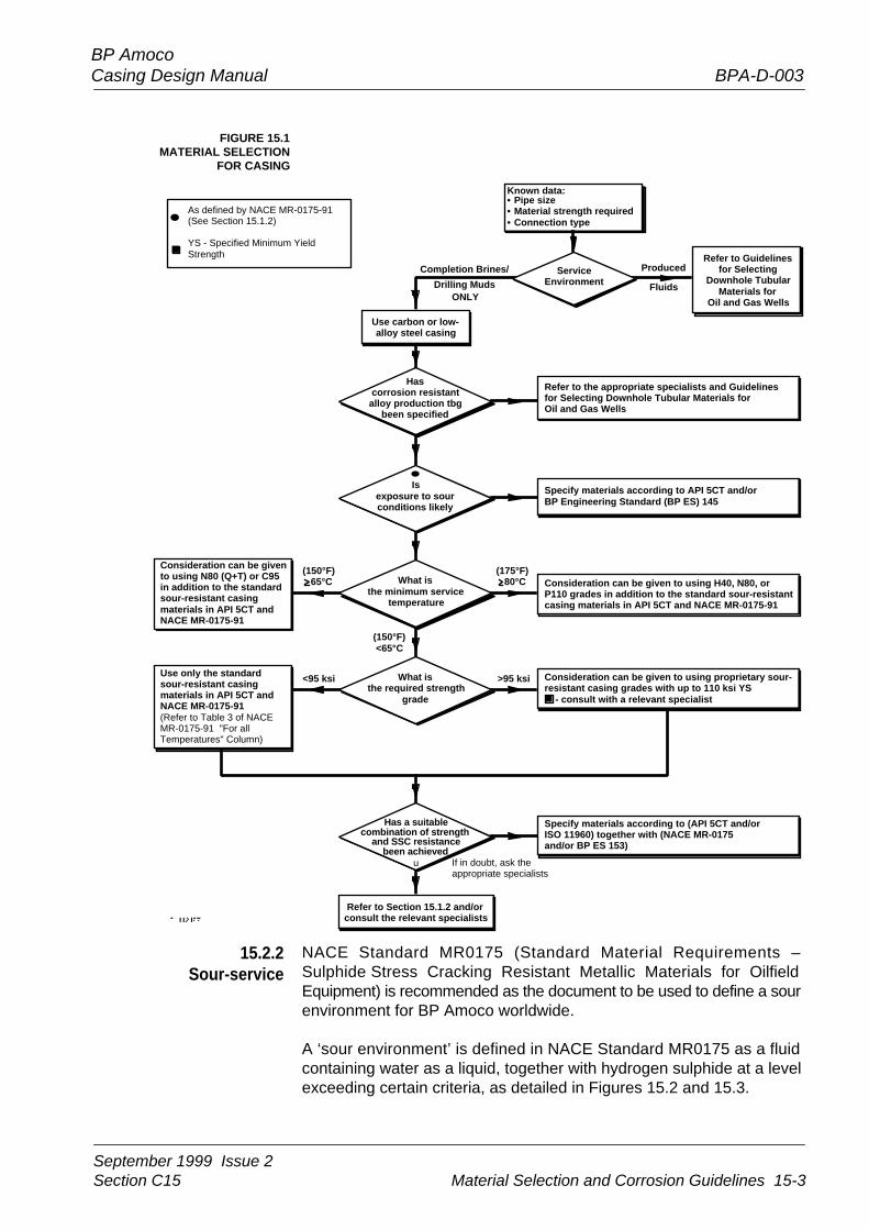
The flowchart in Figure 15.1 can be used when selecting casing materialsthat will be exposed to drilling muds and/or completion brines.
15.2.1Casing Exposed to
Muds and Brines
September 1999 Issue 2Section C15 Material Selection and Corrosion Guidelines 15-3
BP AmocoCasing Design Manual BPA-D-003
FIGURE 15.1MATERIAL SELECTION
FOR CASING
NACE Standard MR0175 (Standard Material Requirements –Sulphide Stress Cracking Resistant Metallic Materials for OilfieldEquipment) is recommended as the document to be used to define a sourenvironment for BP Amoco worldwide.
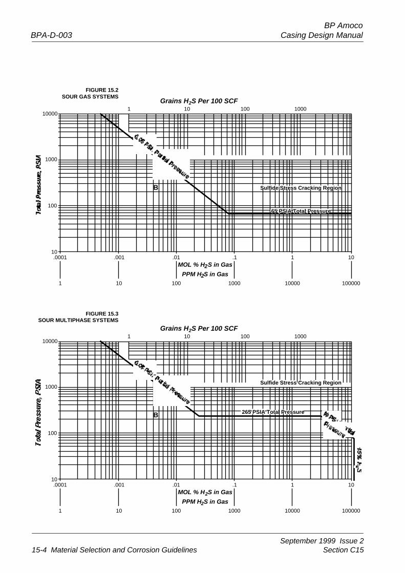
A ‘sour environment’ is defined in NACE Standard MR0175 as a fluidcontaining water as a liquid, together with hydrogen sulphide at a levelexceeding certain criteria, as detailed in Figures 15.2 and 15.3.
15.2.2Sour-service
Known data:•••
Pipe sizeMaterial strength requiredConnection type
ServiceEnvironment
Hascorrosion resistant
alloy production tbgbeen specified
Isexposure to sourconditions likely
What isthe minimum service
temperature
What isthe required strength
grade
Has a suitablecombination of strength
and SSC resistancebeen achieved
Use carbon or low-alloy steel casing
Refer to Guidelinesfor Selecting
Downhole TubularMaterials for
Oil and Gas Wells
Refer to the appropriate specialists and Guidelinesfor Selecting Downhole Tubular Materials forOil and Gas Wells
Specify materials according to API 5CT and/orBP Engineering Standard (BP ES) 145
Consideration can be given to using H40, N80, orP110 grades in addition to the standard sour-resistantcasing materials in API 5CT and NACE MR-0175-91
Consideration can be given to using proprietary sour-resistant casing grades with up to 110 ksi YS - consult with a relevant specialist
Specify materials according to (API 5CT and/orISO 11960) together with (NACE MR-0175and/or BP ES 153)
Consideration can be givento using N80 (Q+T) or C95in addition to the standardsour-resistant casingmaterials in API 5CT andNACE MR-0175-91
Use only the standardsour-resistant casingmaterials in API 5CT andNACE MR-0175-91
Refer to Section 15.1.2 and/orconsult the relevant specialists
As defined by NACE MR-0175-91(See Section 15.1.2)
YS - Specified Minimum YieldStrength
u
Produced
Fluids
Completion Brines/
Drilling MudsONLY
(175°F) 80°C
(150°F) 65°C
<95 ksi >95 ksi
(150°F)<65°C
If in doubt, ask theappropriate specialists
(Refer to Table 3 of NACEMR-0175-91 "For allTemperatures" Column)
September 1999 Issue 215-4 Material Selection and Corrosion Guidelines Section C15
BP AmocoBPA-D-003 Casing Design Manual
FIGURE 15.3SOUR MULTIPHASE SYSTEMS
FIGURE 15.2SOUR GAS SYSTEMS
Sulfide Stress Cracking Region
65 PSIA Total Pressure
10000
1000
100
10.0001 .001 .01 .1 1 10
1 10 100 1000 10000 100000
A
B
Grains H2S Per 100 SCF
MOL % H2S in Gas
PPM H2S in Gas
265 PSIA Total Pressure
Sulfide Stress Cracking Region
10000
1000
100
10.0001 .001 .01 .1 1 10
1 10 100 1000 10000 100000
A
B
Grains H2S Per 100 SCF
MOL % H2S in Gas
PPM H2S in Gas
1 10 100 1000
1 10 100 1000
September 1999 Issue 2Section C15 Material Selection and Corrosion Guidelines 15-5
BP AmocoCasing Design Manual BPA-D-003
From Figures 15.2 and 15.3 it is clear that the definition of sour conditionsis different for gas and oil wells. For the purposes of this definition, anywell with a gas/oil ratio of greater than 5000 standard cubic feet per barrelof oil is taken as a gas well. It is also apparent from these figures that thedefinition of sour conditions is normally based upon the partial pressureof hydrogen sulphide in the gas phase. To determine the partial pressureof hydrogen sulphide in the gas phase, certain field information isrequired.
Considering a gas well, the information required is the bottomholepressure and the mole (or volume) fraction of hydrogen sulphide in thegas. The partial pressure is then calculated simply by multiplying themole fraction of hydrogen sulphide in the gas by the bottomhole pressure.For example, for a 5500m deep gas well with a bottom hole pressure of14,000psi and a hydrogen sulphide content of 5ppm mole, the partialpressure of hydrogen sulphide would be 0.07psia (5/1,000,000*14,000),ie the well would be classified as sour.
For oil wells under circumstances where there is gas present (multiphasewells), the partial pressure of hydrogen sulphide can be estimated bymultiplying the total pressure by the mole fraction of hydrogen sulphide.The situation for oil wells in which there is no gas phase present underdownhole conditions is somewhat different. The partial pressure ofhydrogen sulphide that needs to be calculated is that in a gas phase inequilibrium with that dissolved in the well liquids (oil/water). An alternativedescription of this is the partial pressure of hydrogen sulphide in the gasphase formed at its bubble point. Therefore, a ‘convenient’ method oftenused to calculate the partial pressure is to multiply the bubble pointpressure by the mole fraction of hydrogen sulphide in the gas phase.For example, for a 2000m deep oil well with a bottom hole pressure of2500psi, a bubble point pressure of 1000psia and a hydrogen sulphidecontent of 40ppm mole, the pressure of hydrogen sulphide would be0.04psia, ie the well would be classified as ‘sweet’.
The major concern with sour conditions for casing string is the possibilityof SSC. The mechanism of SSC is described in Appendix 15A. Twoapproaches have been developed to account for SSC in the materialsselection process. These two approaches are described below.
It should be noted that these approaches are only concerned with theresistance of materials to SSC in sour conditions. However, there areother failure mechanisms that may occur in the presence of hydrogensulphide. These need to be borne in mind when selecting materials forsour-service. For example, some steels used in pipelines and vesselsmay suffer from blistering or step-wise cracking as a result of hydrogendamage in sour environments. This aspect is covered for such materialsin BP Guidance for Specification (GS) 136-1. Also, some austeniticstainless steels and highly alloyed materials may suffer from chloridestress corrosion cracking at elevated temperatures (above about 50°C,120°F), this can be aggravated in some circumstances by the presenceof hydrogen sulphide. Again, this aspect is covered to some extent in BPGS 136-1.
September 1999 Issue 215-6 Material Selection and Corrosion Guidelines Section C15
BP AmocoBPA-D-003 Casing Design Manual
TABLE 15.1ACCEPTABLE API
SPECIFICATIONS FORTUBULAR GOODS
NACE Standard MR0175 (Standard Material Requirements – SulphideStress Cracking Resistant Metallic Materials for Oilfield Equipment)
The NACE Standard MR0175 is concerned with the resistance of materialsto SSC in sour conditions. In some countries, such as the United States,the Standard is a legislative requirement, ie it must be applied there. Thisdocument should be referred to for initial information on materials withadequate resistance to SSC for sour conditions.
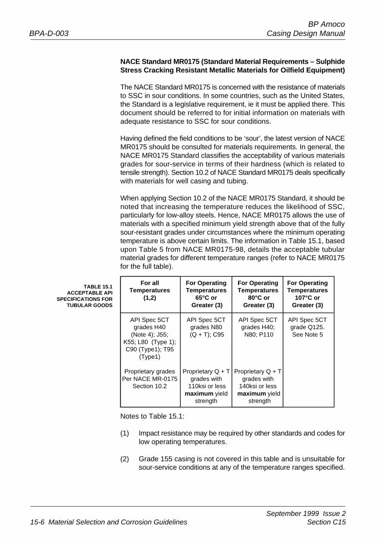
Having defined the field conditions to be ‘sour’, the latest version of NACEMR0175 should be consulted for materials requirements. In general, theNACE MR0175 Standard classifies the acceptability of various materialsgrades for sour-service in terms of their hardness (which is related totensile strength). Section 10.2 of NACE Standard MR0175 deals specificallywith materials for well casing and tubing.
When applying Section 10.2 of the NACE MR0175 Standard, it should benoted that increasing the temperature reduces the likelihood of SSC,particularly for low-alloy steels. Hence, NACE MR0175 allows the use ofmaterials with a specified minimum yield strength above that of the fullysour-resistant grades under circumstances where the minimum operatingtemperature is above certain limits. The information in Table 15.1, basedupon Table 5 from NACE MR0175-98, details the acceptable tubularmaterial grades for different temperature ranges (refer to NACE MR0175for the full table).
For all For Operating For Operating For OperatingTemperatures Temperatures Temperatures Temperatures
(1,2) 65°C or 80°C or 107°C or Greater (3) Greater (3) Greater (3)
API Spec 5CT API Spec 5CT API Spec 5CT API Spec 5CTgrades H40 grades N80 grades H40; grade Q125.
(Note 4); J55; (Q + T); C95 N80; P110 See Note 5K55; L80 (Type 1);C90 (Type1); T95
(Type1)
Proprietary grades Proprietary Q + T Proprietary Q + TPer NACE MR-0175 grades with grades with
Section 10.2 110ksi or less 140ksi or lessmaximum yield maximum yield
strength strength
Notes to Table 15.1:
(1) Impact resistance may be required by other standards and codes forlow operating temperatures.
(2) Grade 155 casing is not covered in this table and is unsuitable forsour-service conditions at any of the temperature ranges specified.
September 1999 Issue 2Section C15 Material Selection and Corrosion Guidelines 15-7
BP AmocoCasing Design Manual BPA-D-003
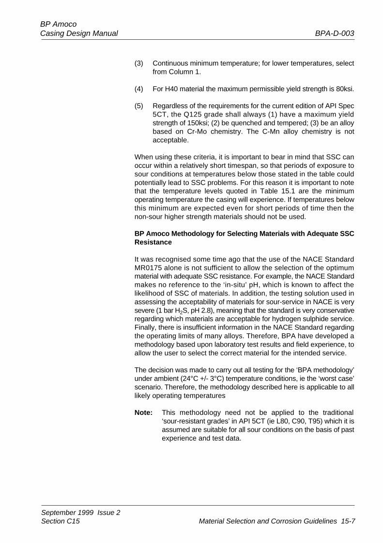
(3) Continuous minimum temperature; for lower temperatures, selectfrom Column 1.
(4) For H40 material the maximum permissible yield strength is 80ksi.
(5) Regardless of the requirements for the current edition of API Spec5CT, the Q125 grade shall always (1) have a maximum yieldstrength of 150ksi; (2) be quenched and tempered; (3) be an alloybased on Cr-Mo chemistry. The C-Mn alloy chemistry is notacceptable.
When using these criteria, it is important to bear in mind that SSC canoccur within a relatively short timespan, so that periods of exposure tosour conditions at temperatures below those stated in the table couldpotentially lead to SSC problems. For this reason it is important to notethat the temperature levels quoted in Table 15.1 are the minimumoperating temperature the casing will experience. If temperatures belowthis minimum are expected even for short periods of time then thenon-sour higher strength materials should not be used.
BP Amoco Methodology for Selecting Materials with Adequate SSCResistance
It was recognised some time ago that the use of the NACE StandardMR0175 alone is not sufficient to allow the selection of the optimummaterial with adequate SSC resistance. For example, the NACE Standardmakes no reference to the ‘in-situ’ pH, which is known to affect thelikelihood of SSC of materials. In addition, the testing solution used inassessing the acceptability of materials for sour-service in NACE is verysevere (1 bar H2S, pH 2.8), meaning that the standard is very conservativeregarding which materials are acceptable for hydrogen sulphide service.Finally, there is insufficient information in the NACE Standard regardingthe operating limits of many alloys. Therefore, BPA have developed amethodology based upon laboratory test results and field experience, toallow the user to select the correct material for the intended service.
The decision was made to carry out all testing for the ‘BPA methodology’under ambient (24°C +/- 3°C) temperature conditions, ie the ‘worst case’scenario. Therefore, the methodology described here is applicable to alllikely operating temperatures
Note: This methodology need not be applied to the traditional‘sour-resistant grades’ in API 5CT (ie L80, C90, T95) which it isassumed are suitable for all sour conditions on the basis of pastexperience and test data.
September 1999 Issue 215-8 Material Selection and Corrosion Guidelines Section C15
BP AmocoBPA-D-003 Casing Design Manual
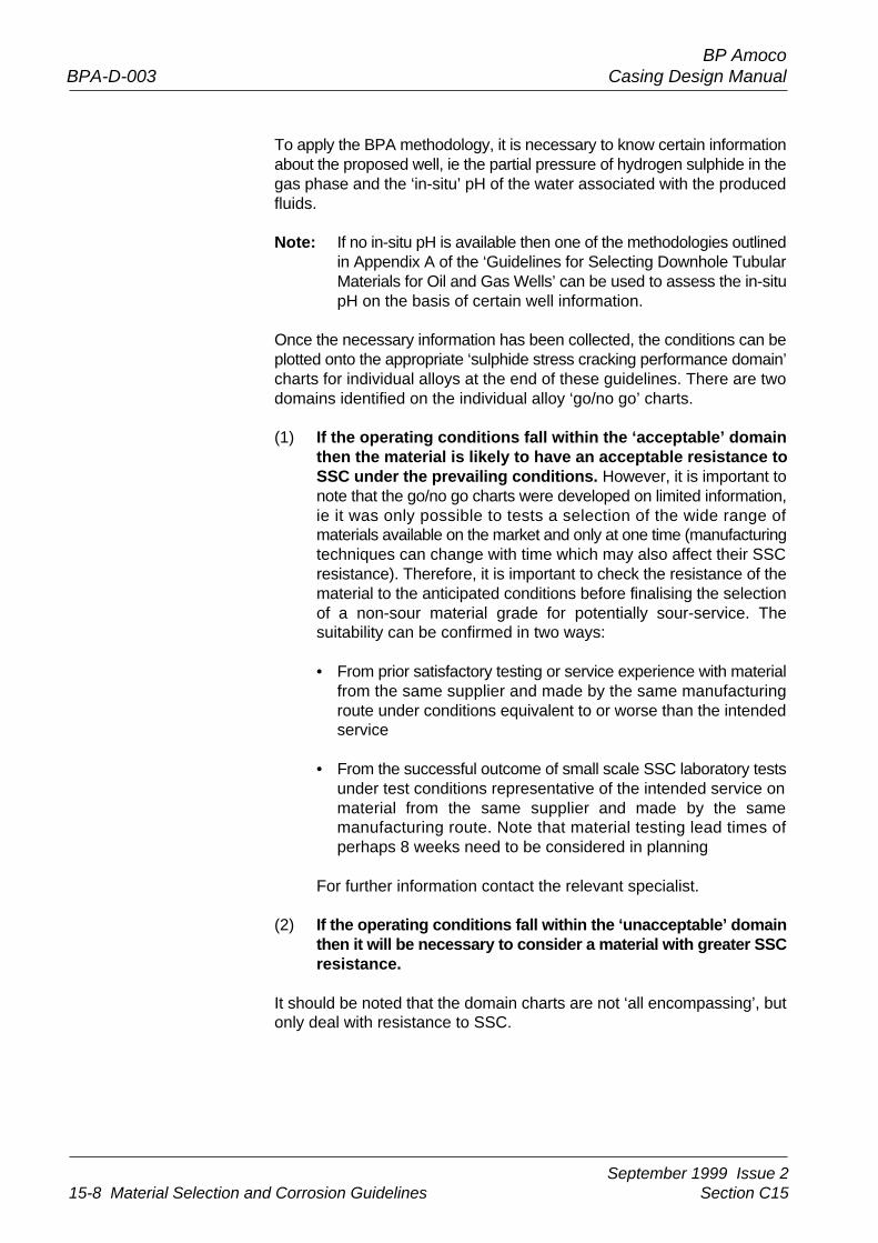
To apply the BPA methodology, it is necessary to know certain informationabout the proposed well, ie the partial pressure of hydrogen sulphide in thegas phase and the ‘in-situ’ pH of the water associated with the producedfluids.
Note: If no in-situ pH is available then one of the methodologies outlinedin Appendix A of the ‘Guidelines for Selecting Downhole TubularMaterials for Oil and Gas Wells’ can be used to assess the in-situpH on the basis of certain well information.
Once the necessary information has been collected, the conditions can beplotted onto the appropriate ‘sulphide stress cracking performance domain’charts for individual alloys at the end of these guidelines. There are twodomains identified on the individual alloy ‘go/no go’ charts.
(1) If the operating conditions fall within the ‘acceptable’ domainthen the material is likely to have an acceptable resistance toSSC under the prevailing conditions. However, it is important tonote that the go/no go charts were developed on limited information,ie it was only possible to tests a selection of the wide range ofmaterials available on the market and only at one time (manufacturingtechniques can change with time which may also affect their SSCresistance). Therefore, it is important to check the resistance of thematerial to the anticipated conditions before finalising the selectionof a non-sour material grade for potentially sour-service. Thesuitability can be confirmed in two ways:
• From prior satisfactory testing or service experience with materialfrom the same supplier and made by the same manufacturingroute under conditions equivalent to or worse than the intendedservice
• From the successful outcome of small scale SSC laboratory testsunder test conditions representative of the intended service onmaterial from the same supplier and made by the samemanufacturing route. Note that material testing lead times ofperhaps 8 weeks need to be considered in planning
For further information contact the relevant specialist.
(2) If the operating conditions fall within the ‘unacceptable’ domainthen it will be necessary to consider a material with greater SSCresistance.
It should be noted that the domain charts are not ‘all encompassing’, butonly deal with resistance to SSC.
September 1999 Issue 2Section C15 Material Selection and Corrosion Guidelines 15-9
BP AmocoCasing Design Manual BPA-D-003
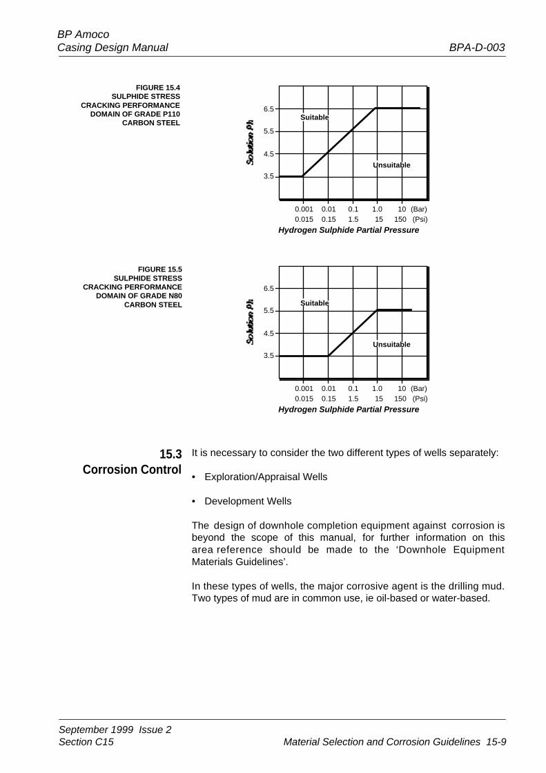
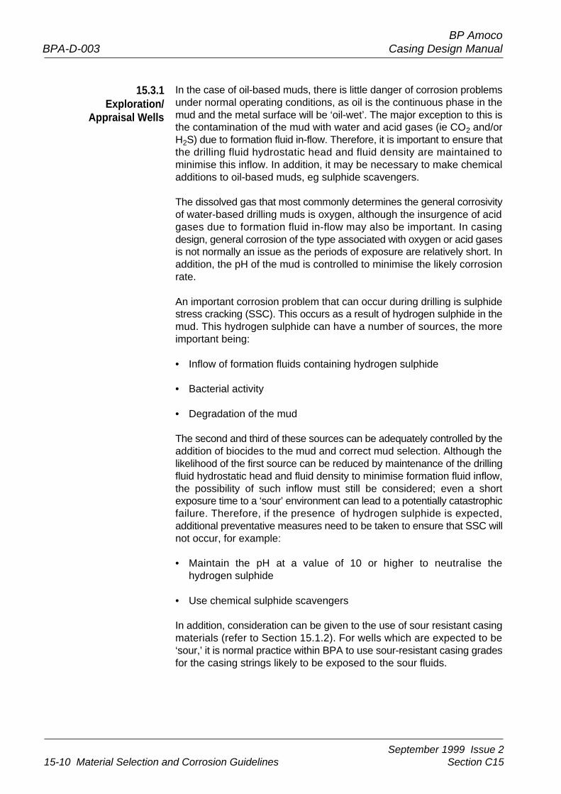
FIGURE 15.4SULPHIDE STRESS
CRACKING PERFORMANCEDOMAIN OF GRADE P110
CARBON STEEL
FIGURE 15.5SULPHIDE STRESS
CRACKING PERFORMANCEDOMAIN OF GRADE N80
CARBON STEEL
15.3Corrosion Control
It is necessary to consider the two different types of wells separately:
• Exploration/Appraisal Wells
• Development Wells
The design of downhole completion equipment against corrosion isbeyond the scope of this manual, for further information on thisarea reference should be made to the ‘Downhole EquipmentMaterials Guidelines’.
In these types of wells, the major corrosive agent is the drilling mud.Two types of mud are in common use, ie oil-based or water-based.
6.5
5.5
4.5
3.5
0.001 0.01 0.1 1.0 10 (Bar)0.015 0.15 1.5 15 150 (Psi)
Hydrogen Sulphide Partial Pressure
Suitable
Unsuitable
6.5
5.5
4.5
3.5
0.001 0.01 0.1 1.0 10 (Bar)0.015 0.15 1.5 15 150 (Psi)
Hydrogen Sulphide Partial Pressure
Suitable
Unsuitable
September 1999 Issue 215-10 Material Selection and Corrosion Guidelines Section C15
BP AmocoBPA-D-003 Casing Design Manual
In the case of oil-based muds, there is little danger of corrosion problemsunder normal operating conditions, as oil is the continuous phase in themud and the metal surface will be ‘oil-wet’. The major exception to this isthe contamination of the mud with water and acid gases (ie CO2 and/orH2S) due to formation fluid in-flow. Therefore, it is important to ensure thatthe drilling fluid hydrostatic head and fluid density are maintained tominimise this inflow. In addition, it may be necessary to make chemicaladditions to oil-based muds, eg sulphide scavengers.
The dissolved gas that most commonly determines the general corrosivityof water-based drilling muds is oxygen, although the insurgence of acidgases due to formation fluid in-flow may also be important. In casingdesign, general corrosion of the type associated with oxygen or acid gasesis not normally an issue as the periods of exposure are relatively short. Inaddition, the pH of the mud is controlled to minimise the likely corrosionrate.
An important corrosion problem that can occur during drilling is sulphidestress cracking (SSC). This occurs as a result of hydrogen sulphide in themud. This hydrogen sulphide can have a number of sources, the moreimportant being:
• Inflow of formation fluids containing hydrogen sulphide
• Bacterial activity
• Degradation of the mud
The second and third of these sources can be adequately controlled by theaddition of biocides to the mud and correct mud selection. Although thelikelihood of the first source can be reduced by maintenance of the drillingfluid hydrostatic head and fluid density to minimise formation fluid inflow,the possibility of such inflow must still be considered; even a shortexposure time to a ‘sour’ environment can lead to a potentially catastrophicfailure. Therefore, if the presence of hydrogen sulphide is expected,additional preventative measures need to be taken to ensure that SSC willnot occur, for example:
• Maintain the pH at a value of 10 or higher to neutralise thehydrogen sulphide
• Use chemical sulphide scavengers
In addition, consideration can be given to the use of sour resistant casingmaterials (refer to Section 15.1.2). For wells which are expected to be‘sour,’ it is normal practice within BPA to use sour-resistant casing gradesfor the casing strings likely to be exposed to the sour fluids.
15.3.1Exploration/
Appraisal Wells
September 1999 Issue 2Section C15 Material Selection and Corrosion Guidelines 15-11
BP AmocoCasing Design Manual BPA-D-003
In the case of high-temperature/high-pressure wells, the situation wassomewhat more complex for UK sector North Sea applications in thepast. Document CSON 59, produced by the Department of Environment,required the operator to provide supporting data that non-sour casingscan be relied upon not to fail catastrophically during:
• A temporary period of exposure to sour reservoir fluid (eg whilstcirculating out a kick or if there is a leak in the test string duringproduction testing) and not subsequently thereafter in the remainderof its service life, or
• The time between first exposure to sour reservoir fluids and completionof evacuation of the drilling installation in the event of total displacementof the well bore contents to such fluids
These requirements have led operators to consider thick-wallsour-resistant casing or proprietary high-strength sour-resistant grades(normally up to 110ksi minimum specified yield strength). These arediscussed in the section on materials selection (Section 15.1) andreference should be made to that section before specifying these typesof material.
Note: CSON 59 has now been superseded by PON13 which imposesno requirement other than notification of expected H2S andincident reporting to PON 11.
Well design should endeavour to contain the corrosive produced fluidswithin the production tubing, eg by the correct selection of tubing materialand the use of tubing strings with premium connections, where necessary.Therefore, the prime consideration in accounting for corrosion in wellcasing design is to ensure the correct selection of the annulus fluid.However, it is recognised that tubing leaks and subsequent pressurisedannuli are possibilities. Therefore, measures need to be taken to ensurethe adequate protection of the casing under such circumstances.These aspects are discussed in this section.
Any part of the casing that is likely to be exposed to the produced fluidsfor a significant length of time should be designed to withstand such anenvironment. This means that when designing such casing, considerationsvery similar to those given for production tubing need to be addressedwhen selecting materials. This area is addressed in the ‘Guidelines forSelecting Downhole Tubular Materials for Oil and Gas Wells’.
15.3.2Development Wells
September 1999 Issue 215-12 Material Selection and Corrosion Guidelines Section C15
BP AmocoBPA-D-003 Casing Design Manual
Corrosion Control in Completion Fluids
Completion fluids can be defined as any borehole fluid placed across theproducing zone prior to bringing on a well. These fluids are field/wellspecific and fulfil many roles. Brine completion fluids are used in welltesting operations, workovers, completions and as packer fluids. Thefunction in a completion is to fill the annulus space between the productiontubing and casing.
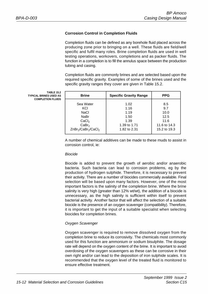
Completion fluids are commonly brines and are selected based upon therequired specific gravity. Examples of some of the brines used and thespecific gravity ranges they cover are given in Table 15.2.
TABLE 15.2TYPICAL BRINES USED AS
COMPLETION FLUIDSBrine Specific Gravity Range PPG
Sea Water 1.02 8.5KCl 1.16 9.7
NaCl 1.19 10.0NaBr 1.50 12.5CaCl2 1.39 11.6CaBr2 1.39 to 1.71 11.6 to 14.3
ZnBr2/CaBr2/CaCl2 1.82 to 2.31 15.2 to 19.3
A number of chemical additives can be made to these muds to assist incorrosion control, ie:
Biocide
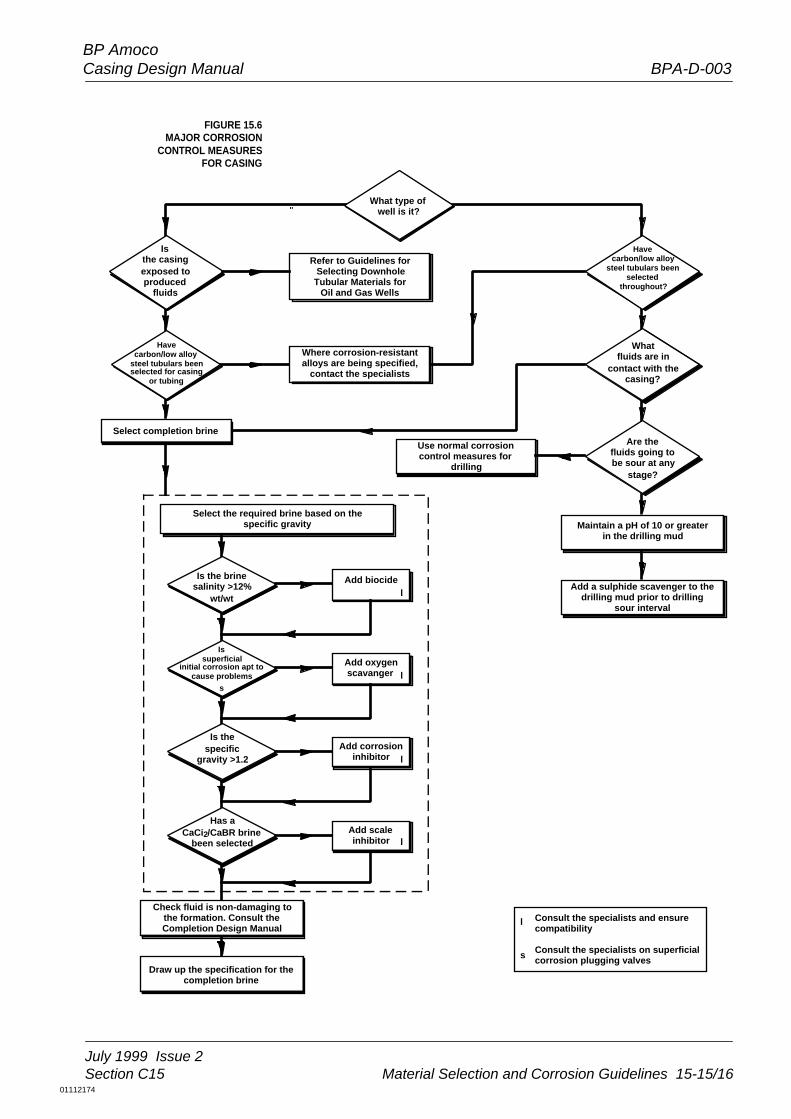
Biocide is added to prevent the growth of aerobic and/or anaerobicbacteria. Such bacteria can lead to corrosion problems, eg by theproduction of hydrogen sulphide. Therefore, it is necessary to preventtheir activity. There are a number of biocides commercially available. Finalselection will be based upon many factors. However, one of the mostimportant factors is the salinity of the completion brine. Where the brinesalinity is very high (greater than 12% wt/wt), the addition of a biocide isunnecessary, as the high salinity is sufficient within itself to preventbacterial activity. Another factor that will affect the selection of a suitablebiocide is the presence of an oxygen scavenger (compatibility). Therefore,it is important to get the input of a suitable specialist when selectingbiocides for completion brines.
Oxygen Scavenger
Oxygen scavenger is required to remove dissolved oxygen from thecompletion brine to reduce its corrosivity. The chemicals most commonlyused for this function are ammonium or sodium bisulphite. The dosagerate will depend on the oxygen content of the brine. It is important to avoidoverdosing of the oxygen scavengers as these can be corrosive in theirown right and/or can lead to the deposition of iron sulphide scales. It isrecommended that the oxygen level of the treated fluid is monitored toensure effective treatment.
September 1999 Issue 2Section C15 Material Selection and Corrosion Guidelines 15-13
BP AmocoCasing Design Manual BPA-D-003
If the completion brines are not deaerated, the available oxygen may inany case be quickly consumed by the superficial corrosion of the carbon/low alloy casing where the two are in contact. Therefore, a decision mustbe made on whether or not an oxygen scavenger is required. This decisionneeds to be based upon a number of factors. For example, even the shortperiod of enhanced corrosion in non-deaerated solutions may producesignificant quantities of corrosion product. There may be concerns thatthis corrosion product dropping to the bottom of the annulus will blockinjection valves. Therefore, future use of the annulus needs to beconsidered. Additionally, if corrosion-resistant alloy (CRA) tubulars arespecified then the presence of oxygen may initiate corrosion, eg pittingcorrosion, crevice corrosion, galvanic corrosion, or even SSC, especiallyif the oxygen is not rapidly consumed by superficial corrosion of carbon/low alloy steel (eg if the fluids are inside the tubing for any reason, areaswhere carbon steel is not present in the region of CRA tubulars). If in anydoubt, the relevant specialists should be consulted.
Corrosion Inhibitor
Some of the high-density brines can be corrosive in their own right(eg zinc bromide). In such circumstances it will often be necessary to usea film-forming corrosion inhibitor to reduce the corrosion rates topermissible levels. There are many corrosion inhibitors available on themarket therefore selection should be made with care. It is recommendedthat due reference is made to the relevant specialists. One corrosioninhibitor commonly used is a quarternary amine, which is dosed at a rateof 5% v/v (50,000ppm). As a rule of thumb, the cut-off point whendeciding whether to consider a corrosion inhibitor or not is a specificgravity of 1.2 (10ppg), with a corrosion inhibitor being given considerationabove this specific gravity. Compatibility with the formation itself shouldalso be considered to avoid formation swelling or blocking.
Scale Inhibitor
This is the final chemical additive in completion brines. It is not added tocontrol the corrosivity, but rather to prevent scales forming when thecompletion brine comes into contact with the formation brine. If acompatible completion brine has been selected, or where the completionbrine will not come into contact with the formation fluids, a scale inhibitoris unnecessary. For example, where a sodium or potassium based brineis used, the high solubility of the products formed by mixing with formationwater means that the addition of a scale inhibitor is unnecessary. Undernormal conditions, scale inhibitors are only necessary in calcium chloride/bromide completion brines. Under such circumstances, it is recommendedthat the relevant specialist be contacted.
September 1999 Issue 215-14 Material Selection and Corrosion Guidelines Section C15
BP AmocoBPA-D-003 Casing Design Manual
To avoid corrosion problems resulting from completion fluids, the use ofalternative ‘non-aqueous’ fluids is sometimes considered, eg diesel oil. Ithas been found that one alternative fluid (bromoil/densoil) can be corrosiveat elevated temperatures (>400°F, 200°C). Therefore, care needs to beexercised when using these types of fluid.
External corrosion of casing can be a problem, especially where thecasing passes through aquifers. If such problems are expected orencountered, consideration may need to be given to external cathodicprotection or cementing across the zone of concern. The design of suchsystems is outside the scope of this manual and reference should be madeto the appropriate specialists.
The purpose of the flow diagram in Figure 15.6 is to assist in deciding thecorrosion control measures required for the fluids normally in contact withthe casing, ie completion brines or drilling muds. When selecting thechemical treatment package for completion brine, it is important to contactthe relevant specialist(s), to ensure the suitability/compatibility of thevarious additives.
15.4External Corrosion
15.5Flowchart for
Corrosion ControlMeasures
September 1999 Issue 2Section C15 Material Selection and Corrosion Guidelines 15-15
BP AmocoCasing Design Manual BPA-D-003
FIGURE 15.6MAJOR CORROSION
CONTROL MEASURESFOR CASING
July 1999 Issue 2Section C15 Material Selection and Corrosion Guidelines 15-15/16
What type ofwell is it?
Havecarbon/low alloy
steel tubulars beenselected
throughout?
Isthe casingexposed toproduced
fluids
Havecarbon/low alloy
steel tubulars beenselected for casing
or tubing
Whatfluids are in
contact with thecasing?
Are thefluids going tobe sour at any
stage?
Is the brinesalinity >12%
wt/wt
Issuperficial
initial corrosion apt tocause problems
Is thespecific
gravity >1.2
Has aCaCi2/CaBR brine
been selected
Refer to Guidelines forSelecting Downhole
Tubular Materials forOil and Gas Wells
Where corrosion-resistantalloys are being specified,
contact the specialists
Use normal corrosioncontrol measures for
drilling
Maintain a pH of 10 or greaterin the drilling mud
Add a sulphide scavenger to thedrilling mud prior to drilling
sour interval
Check fluid is non-damaging tothe formation. Consult theCompletion Design Manual
Draw up the specification for thecompletion brine
Select completion brine
s
Select the required brine based on thespecific gravity
Add biocide
Add oxygenscavanger
Add corrosioninhibitor
Add scaleinhibitor
l
l
l
l
Consult the specialists and ensurecompatibility
Consult the specialists on superficialcorrosion plugging valves
l
s
01112174
September 1999 Issue 2Section C15 Material Selection and Corrosion Guidelines 15A-1
BP AmocoCasing Design Manual BPA-D-003
One of the prerequisites for corrosion to occur is the presence of anaqueous phase, although even a trace of water can lead to corrosion.
Corrosion is an electrochemical process, so that an electrical currentflows during corrosion. For an electrical current to flow, there must be adriving force, ie a voltage source, and a complete electrical circuit.
The voltage source is the metal itself. All metals contain stored energy,eg as a result of refining, mechanical working. This means that metal willadopt an electrical potential when it is put into an aqueous solution,known as the ‘equilibrium potential’.
FIGURE 15A.1DIAGRAMMATICAL
REPRESENTATION OF THECORROSION PROCESS FOR IRON
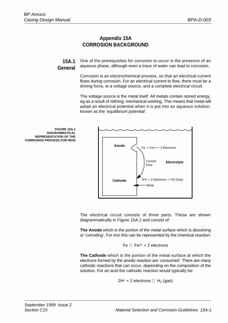
The electrical circuit consists of three parts. These are showndiagrammatically in Figure 15A.1 and consist of:
The Anode which is the portion of the metal surface which is dissolvingor ‘corroding’. For iron this can be represented by the chemical reaction:
Fe ⇒ Fe2+ + 2 electrons
The Cathode which is the portion of the metal surface at which theelectrons formed by the anodic reaction are ‘consumed’. There are manycathodic reactions that can occur, depending on the composition of thesolution. For an acid the cathodic reaction would typically be:
2H+ + 2 electrons ⇒ H2 (gas)
Appendix 15ACORROSION BACKGROUND
15A.1General
Anode
Cathode
Fe -> Fe++ + 2 Electrons
2H+ + 2 Electrons -> H2 (Gas)
CurrentFlow
Electrolyte
Metal
September 1999 Issue 215A-2 Material Selection and Corrosion Guidelines Section C15
BP AmocoBPA-D-003 Casing Design Manual
The Electrolyte which is the electrically conductive solution on the metalsurface through which the electrical current (or electrons) necessary tosupport the corrosion process flows.
In the case where there is no externally applied electrical current, theanodic and cathodic reactions are balanced, ie there will be no ‘total’current flow measured.
The reasons why some areas of the metal surface act as anodes,whereas others act as cathodes, are complex. A major factor isinhomogeneity in the metal surface and/or electrolyte. In general corrosion,the anodes and cathodes will be randomly distributed over the surfaceand will ‘move’ during the corrosion process. In localised corrosion,eg pitting, the anodes will be restricted to certain, small areas.
Many different types of corrosion damage can occur. The more likely tobe experienced by downhole casing can be classified as follows:
(1) General Corrosion
This results in a fairly uniform loss of material across the surfaceof a component, leading to a loss in load carrying capacity, eg theability to contain a pressure, tension, collapse.
(2) Localised Corrosion
This results in uneven wastage of the component eg pittingcorrosion. Pitting corrosion is a particularly damaging form ofcorrosion in which components can fail by perforation with only asmall percentage weight-loss. In addition, pits will act as stress-concentrators, reducing the load-carrying capacity of thecomponent. Alternatively, localised corrosion may occur at particularlocations, eg crevices, mixed metal sites (galvanic attack), areasof high turbulence (erosion-corrosion).
(3) Environment-sensitive Cracking (ESC)
These mechanisms can lead to catastrophic, brittle failures.Cracking can occur rapidly and without the accompaniment ofsignificant material wastage. In addition, the cracks can be veryfine, making them difficult to detect using conventional inspectiontechniques. Examples of ESC are sulphide stress cracking (SSC),chloride stress corrosion cracking (CSC) and corrosion-fatigue.
September 1999 Issue 2Section C15 Material Selection and Corrosion Guidelines 15A-3
BP AmocoCasing Design Manual BPA-D-003
As has already been indicated, there are many mechanisms by whichcorrosion damage can occur. This section covers the corrosion damagethat can be accrued as a result of chemical contaminants and some ofthe other corrosion mechanisms that must be considered in casingdesign.
Carbon dioxide is commonly found associated with well fluids. Carbondioxide dissolved in water forms a weak acid, known as carbonic acid,which can cause corrosion. This is of particular importance for carbonsteel, in which case an iron carbonate film is sometimes formed on themetal surface. CO2 corrosion of carbon steels often occurs at locationswhere the iron carbonate film is deficient, resulting in a particular form oflocalised pitting corrosion, known as ‘mesa’ attack. In circumstanceswhere there is no iron carbonate film, the corrosion will be general.
The rate of CO2 corrosion will be dependent on a number of factors,including CO2 partial pressure, pH, temperature, flow velocity, andthe presence and nature of other chemical species (eg oxygen, chlorides,H2S).
There are numerous guidelines that can be used to predict the severityof CO2 corrosion. Contact relevant specialist.
There are a number of possible sources of hydrogen sulphide indownhole fluids. These include:
• Associated with the well fluids
• Generated as a result of bacterial activity. In this case sulphate-reducingbacteria (SRBs) can reduce sulphates in the fluids to hydrogensulphide
• Breakdown products of chemical species in the fluids. One suchsource could be bisulphites added to remove oxygen frominjection water
Hydrogen sulphide dissolved in water can react with a steel surface,producing an iron sulphide scale. H2S corrosion often results in deep pitsin regions where the iron sulphide scale is not present. In practice, thistype of H2S corrosion has little practical significance unless the H2Scontent is high, ie several mole %.
15A.2Corrosion
Mechanisms
15A.2.1Carbon Dioxide
15A.2.2Hydrogen Sulphide
September 1999 Issue 215A-4 Material Selection and Corrosion Guidelines Section C15
BP AmocoBPA-D-003 Casing Design Manual
Of greater importance, at the relatively low H2S levels often found indownhole fluids, is the mechanism known as ‘sulph ide stress cracking’(SSC). Sulphide stress cracking occurs as a result of the entry of atomichydrogen into the metal. Aqueous corrosion will produce atomic hydrogenwhich would normally tend to recombine via the reaction:
2H+ 2 electrons ⇒ H + H ⇒ H2 (gas)
These hydrogen gas molecules are too large to enter the metal and arethus not harmful to it. However, hydrogen sulphide is thought to discouragethe recombination of hydrogen atoms to form H2 gas and henceencourages the entry of atomic hydrogen into the metal. Once in themetal the atomic hydrogen will diffuse to ‘trap’ sites, where it will lead toa local increase in the stress and/or a reduction in the strength of themetal lattice. For a material under load, there is evidence to suggest thatthe atomic hydrogen will concentrate near stress concentrators and maygive rise to crack initiation at such points, hence leading to a brittle-likefracture. This type of cracking can occur quite rapidly. Thus, even ifmaterials are only to be exposed to sour conditions for short periods oftime, they must be resistant to SSC. This aspect is covered in some detailin Paragraph 15.1 (Materials Selection) of this manual.
The presence of dissolved oxygen can have a marked influence on thecorrosion of oil-field goods. High corrosion rates can result even atrelatively low concentrations of dissolved oxygen (much less than1ppm). In this process iron is converted by a corrosion reaction to oxidesand/or hydroxides. The cathodic reaction in this case is:
O2 + 2H2O + 4 electrons ⇒ 4OH-
The corrosion rate in oxygenated near-neutral solutions is often controlledby the rate at which oxygen can diffuse to the cathodic areas to supportthe corrosion reaction. As such, the corrosion rate will be increased byflow etc.
Oxygen corrosion is not normally a problem with produced fluids, as theycontain no dissolved oxygen. However, it can be a significant issue inwater-based drilling muds, in which case it may be necessary to controlthe dissolved oxygen content using oxygen scavengers. Another areawhere oxygen corrosion can be a significant issue is in injection watersystems, in which case care must be taken to reduce the dissolvedoxygen to acceptable levels, eg using gas stripping or vacuum degassing.
15A.2.3Oxygen
September 1999 Issue 2Section C15 Material Selection and Corrosion Guidelines 15A-5
BP AmocoCasing Design Manual BPA-D-003
Halide ions, eg chloride and bromide ions, are present in many of thefluids likely to be encountered downhole, ie formation waters,injection waters, completion brines, workover fluids, etc.
Halide ions can cause localised corrosion damage to materials used fordownhole equipment in the form of corrosion pitting and/or crevicecorrosion. In addition, they can increase the corrosion damage resultingfrom the effect of other corrodants.
Halide ions can also give rise to stress corrosion cracking (SCC) ofsusceptible materials, principally austenitic stainless steels. This type ofcracking will normally only occur at elevated temperatures, typically above50°C (120°F) for austenitic stainless steels, and under the action oftensile stresses. This can also include residual stresses from mechanicalworking.
Stress corrosion cracking can be defined as crack initiation and growthin an alloy caused by the conjoint action of corrosion and tensile stress.This cracking can occur at stresses well below the yield strength.The mechanism by which this occurs is not fully understood, but itrequires the presence of certain specific alloy/environment combinations,eg austenitic stainless steel in chloride-containing solutions. The result ofSCC is that normally ductile materials can suffer from catastrophic,apparently brittle, failures.
This is the preferential corrosion that can occur to one of the metals, whentwo different metals are electrically coupled in a corrosive environment.In such a couple, one of the metals will act as an anode (ie it will corrodeat an enhanced rate) and the other will act as a cathode (ie there will bea certain degree of protection). The susceptibility of a material coupletowards galvanic corrosion of the ‘anodic’ metal (ie the metal with thelower equilibrium potential) is influenced by a number of factors, such asthe conductivity of the corrosive medium, the relative surface area of thetwo metal components and the difference in the equilibrium potentials ofthe two metals in the corrosive environment.
15A.2.5Galvanic Corrosion
15A.2.4Halide Ions
September 1999 Issue 215A-6 Material Selection and Corrosion Guidelines Section C15
BP AmocoBPA-D-003 Casing Design Manual
There are two types of localised corrosion that are likely to be encountereddownhole, ie corrosion pitting and crevice corrosion. As has alreadybeen indicated, corrosion pitting occurs when certain regions in themetal act as strong anodes. An example of this is the corrosion pitting ofcertain stainless steels in chloride-containing environments. In this case,pitting is enhanced by the presence of dissolved oxygen. The pittingprocess is strongly affected by temperature. There are often temperaturesbelow which corrosion pitting will not occur in a particular environment,this is known as the ‘critical pitting temperature’. Pitting is more damagingthan general corrosion as it can result in penetration in much shortertimes and is more difficult to detect. This is an aspect that should beborne in mind when selecting materials for downhole service, particularlycorrosion-resistant alloys.
Crevice corrosion is the localised damage that can result at a narrow gapor ‘crevice’ between two adjacent components. The crevice may bebetween two similar materials, two different materials (in which galvaniccorrosion may also play a role), or even between a metal and a non-metal(eg elastomers). An important factor in determining whether crevicecorrosion will occur is the size of the gap. Crevice corrosion is oftenexacerbated at higher temperatures. The local environment producedwithin a crevice can be quite different to the bulk fluid environment,leading to corrosion damage which could not be predicted from thegeneral fluid composition.
15A.2.6Localised Corrosion