Embed Size (px)
DESCRIPTION
information about casing calculation in oil well drilling
Citation preview

Copyright 2007, , All rights reserved
Casing String and Suspension
Overview

Copyright 2007, , All rights reserved 2
Casing
Casing String Types
The reasons for running and cementing casing:
– Isolate zones,
– Prevent mud contamination of fresh water aquifers,
– Support well head equipment and BOPs,
– Keep hole open
– Seal off lost circulation zones,
– Control inflow from the producing zone(s),

Copyright 2007, , All rights reserved 3
7” Production casing
Exploration well
5 casings
Development well
4 casings
30”
20”
13-3/8”
Intermediate
9-5/8”
Reservoir
Conductor
Surface casing
20”
13-3/8”
9-5/8”
Offset
data
Intermediate
Example of Casing Series

Copyright 2007, , All rights reserved 4
Casing (1)
Casing String Type: Drive Pipe
– Commonly pile driven or jetted to a shallow depth (e.g. 100 ft),
– The primary purpose is to protect unconsolidated surface soils
from erosion,
– They are typically of large diameter
(more than 20 inches),
– Joints are normally welded together

Copyright 2007, , All rights reserved 5
Casing (2)
Casing String Types: Conductor Pipe
This is the first casing to be run when there is no drive pipe to prevent washing out under the rig,
It is the string on which Divertor or Bell nipple can be set,
It is cemented to surface or seabed. It supports the wellhead and subsequent casing strings and its setting is critical in terms of compressional loading and integrity of the cement,
Common Sizes and Depths:
– 30” - 20” Welded, 20” - 16” Threaded,
– 30’ - 200’ (< 100’ common).
Copyright 2007, , All rights reserved 6
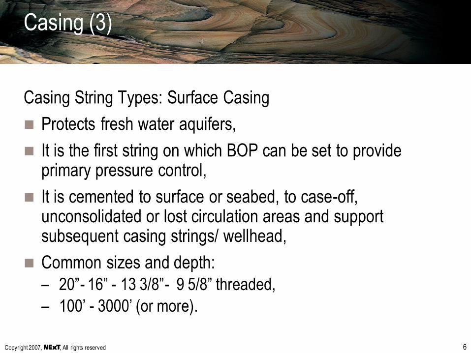
Casing (3)
Casing String Types: Surface Casing
Protects fresh water aquifers,
It is the first string on which BOP can be set to provide primary pressure control,
It is cemented to surface or seabed, to case-off, unconsolidated or lost circulation areas and support subsequent casing strings/ wellhead,
Common sizes and depth:
– 20”- 16” - 13 3/8”- 9 5/8” threaded,
– 100’ - 3000’ (or more).
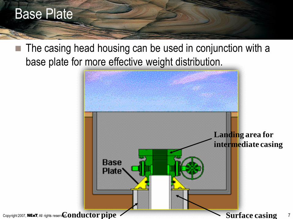
Copyright 2007, , All rights reserved 7Conductor pipe Surface casing
Landing area for
intermediate casing
Base Plate
The casing head housing can be used in conjunction with a
base plate for more effective weight distribution.

Copyright 2007, , All rights reserved 8
Slip-on weld bottom
connection
Threaded bottom
connectionOR
Casing Head on Surface casing (Bottom
Connection)

Copyright 2007, , All rights reserved 9
Casing (4)
Casing String Types: Intermediate Casing
Separates hole into workable sections,
The number of intermediate strings set depends on:– Fracture Pressure last shoe,
– Proximity to a potential reservoir. (It is good practice to set intermediate string above reservoir),
– Hole problems (i.e. lost circulation, salt section, differential sticking, caving, over-pressurized zones),
The casing is normally cemented in the previous shoe or to surface. (could be cemented in two stages),
Common sizes and depths:– 13 3/8”, 10 3/4”, 9 5/8”,
– 3000’ to 10,000’.

Copyright 2007, , All rights reserved 10
Unconsolidated
Swelling
Abrasive
Instability
Fractured
Unsealed fault
Overpressured
Salt layer
Hole problems

Copyright 2007, , All rights reserved 11
Conductor
Surface casing
Intermediate
casing
Landing area
Casing Hangers

Copyright 2007, , All rights reserved 12
Functions of casing hangers
1. Suspends intermediate or production casing string
2. Seals off the casing annulus
3. Centres the casing string in the head (or spool)

Copyright 2007, , All rights reserved 13
SLIPS
BOWL
ELASTOMER
SEAL ELEMENT
Slip type casing hanger
1. Wrap around casing slips with sealing capability
2. Seal energized by casing weight

Copyright 2007, , All rights reserved 14
Second element of the wellhead
Casing Head Spools

Copyright 2007, , All rights reserved 15
Functions of casing head spools
Seals off (packs off) around current (surface casing) string,
Provides support for next casing with hanger
– Provides support for well control equipment (BOP Stack)
– Sealing the well bore from the atmosphere
– Controlling access to the well bore :
• for pressure control
• fluid returns.

Copyright 2007, , All rights reserved 16
Casing series & casing heads / spools

Copyright 2007, , All rights reserved 17
Seals off (packs off)
designed to fit around OD
of current casing
Side outlets
threaded or
studded
Top connection
Landing area for
next Casing Hanger
Bottom connection compatible
with the top connection on the
previous casing head or spool
Description of a spool

Copyright 2007, , All rights reserved 18
Casing (5)
Casing String Types: Production Casing
Final string to be run for production or testing,
The primary purpose is to isolate the production zones thus
allowing proper control of the reservoir,
Cementing is very important to prevent communication in the
annulus,
Covers worn or damaged intermediate string,
Common sizes: 7”, 7 5/8”, & 9 5/8”.

Copyright 2007, , All rights reserved 19
Liners (1)
Purpose:
Mostly same as production casing,
Rig unable to lift long string of casing in Deep Wells,
Types of Liners
Production Liners: Most common to save $$,
Drilling Liners: Cover problem zone or cover worn-out casing
in order to be able to continue drilling,
Common sizes: 4 1/2”, 5”, 7”.

Copyright 2007, , All rights reserved 20
Liners (2)
Production Liner:
Liner Hanger hangs off the liner
in the last casing.
Liner Lap is filled with cement
which provides a seal.
Some Liner Hangers are
equipped with a rubber seal
element,
Liner Hanger Packer Liner
Last casing
Liner
hanger
Liner Lap

Copyright 2007, , All rights reserved 21
Liners (3)
Production Liner:
Tie-Back:
– The integration of the liner with
casing from top of liner to
surface,
– To cover corroded casing or
damaged zone above liner,
– Sometimes cemented in place,
– Additional casing spool required
to suspend tie-back,
– This is often done if production
is still commercially viable.
TIE BACK
STINGER
WITH
SEALS
LINER
PBR
Copyright 2007, , All rights reserved 22
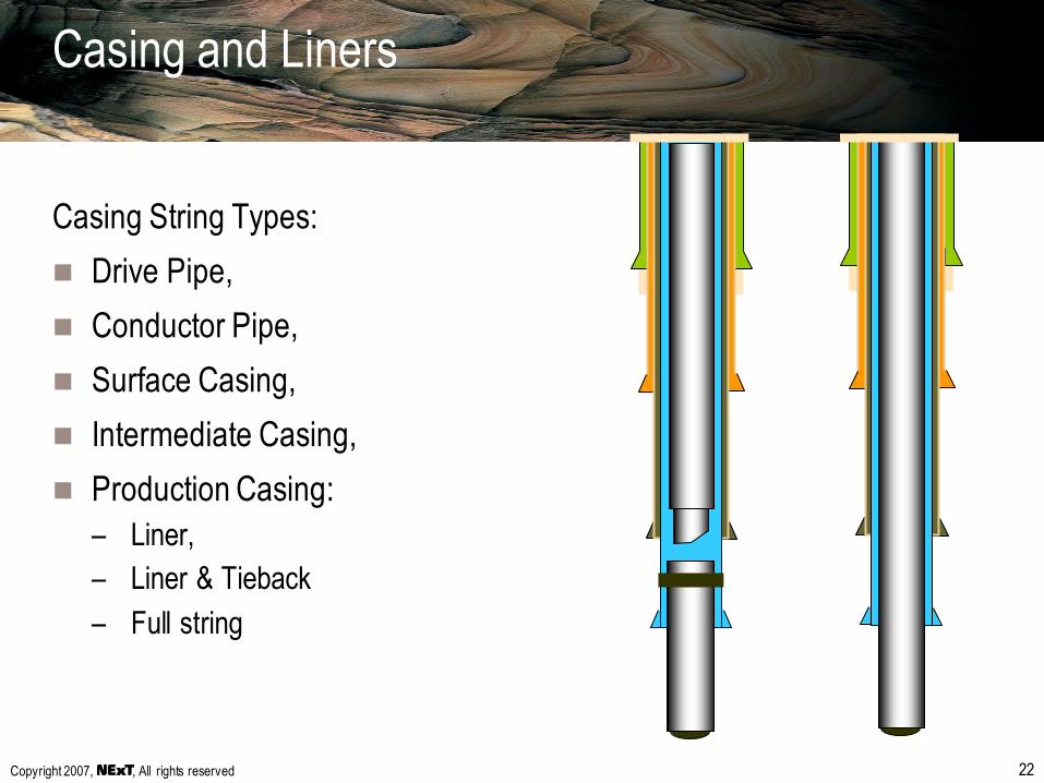
Casing and Liners
Casing String Types:
Drive Pipe,
Conductor Pipe,
Surface Casing,
Intermediate Casing,
Production Casing:
– Liner,
– Liner & Tieback
– Full string

Copyright 2007, , All rights reserved 23
Effects of tubing leak

Copyright 2007, , All rights reserved 24
13 3/8” at
2931 ft
9 5/8” at
5451 ft
Gas Sand
Shale
TOC 2610 ft
Top gas sand 2988 ft
EFFECTS:
prod csg collapse
frac of cement
A B
Source of pressure built-up:
•casing leak
•micro annuli in cement
•poor cementation
Effect of pressure in B or C annulus
Copyright 2007, , All rights reserved 25
Casing Design Considerations
The end product of well design and construction is a
pressure vessel capable of withstanding the expected
internal and external pressures and axial loading,
Casing loads:
– tension
– collapse
– burst
Copyright 2007, , All rights reserved 26
Casing design considerations
Tension:
– Where: highest at top joint
– Design: add bending forces, shock loads
Collapse:
– Where: bottom of string
– Design: empty casing, mud outside, mobile formations, no cement
Burst:
– Where: top of string
– Design: no cement, mud outside, gas filled casing