Embed Size (px)
Citation preview

Service Information
Service Information No. 20/2006 (Version 01) LWL/VK/baj/18.09.06
Page 1/17 20200601SI_gb.doc
After Sales Service International
Appliance Documentation
CASS 1100 from Index 10 (R134a) from Index 50 (CO2)
Cassette for FKDv 3412
Service Information No. 20/2006 (Version 01) CASS 1100 from Index 10 / from Index 50
Page 2/17
Contents 1.0 Operating and control elements 3 2.0 Functions at a glance 3 3.0 Description of appliance 4
3.1 Schematic diagram 4 3.2 CASS 1100-10 5
3.2.1 Design 5 3.2.2 View 5
3.3 CASS 1100-50 6 3.3.1 General information on CO2 6 3.3.2 Vapour-pressure curve for CO2 6 3.3.3 Log p, h diagram for CO2 with transcritical cycle (general) 7 3.3.4 Schematic diagram of refrigeration system 7 3.3.5 Design 8 3.3.6 View 8 3.3.7 Special components 9
3.3.7.1 View of compressor 9 3.3.7.2 View of safety pressure limiter 9
4.0 Control and functional components 10 5.0 Refrigeration circuit 11
5.1 CASS 1100 Index 10 11 5.2 CASS 1100 Index 50 11
6.0 Special features 12 6.1 EMS controller (Energy Management System) 12
6.1.1 Determining the frequency of use 12 6.1.2 Creating the matrix 13 6.1.3 pull-down (= rapid cooling to set operating value) 13 6.1.4 softstart 13
6.2 Delivery options 13 6.3 Operating instructions 13
7.0 Replacement of parts 14 7.1 Cassette disassembly 14 7.2 Changing the electronics and sensor 14 7.3 Changing the interior fan 15 7.4 Changing the condenser fans 15
8.0 Technical data 16 9.0 Checking the cassette 16
9.1 Checking the electrical components 16 9.2 Visual check 16
10.0 Displays on electronic unit 17 10.1 Status display 17 10.2 Readout options (by button combinations) 17

Service Information No. 20/2006 (Version 01) CASS 1100 from Index 10 / from Index 50
Page 3/17
1.0 Operating and control elements
In the fitted condition, the cassette and hence also the electronics are situated behind the plinth. Operation by the customer is not intended and is reserved for authorised persons!
2.0 Functions at a glance
Control: Electronic
Temperature display: Digital
Door alarm: Visual and audible (door switch in FKDv 3412)
Temperature alarm: No
Preset values +2°C for operating mode (during business hours) +6°C for energy-saving mode (outside business hours)
Cooling: Dynamic
Defrosting: Automatic
Refrigerating system: CASS 1100-10 Standard compressor CASS 1100-50 2-stage rolling piston compressor
Operating elements 5 Save button for setting temperature 6 Button for setting temperature lower (also for parameter changes) 7 Button for setting temperature higher (also for parameter changes) 8 Button for initiating a defrosting phase
Function element 9 Infrared sensor
5 6
1
4
3
2
7 8
9
Control elements 1 Display 2 LED for compressor ON 3 LED for interior fan ON 4 LED for overtemperature, condenser

Service Information No. 20/2006 (Version 01) CASS 1100 from Index 10 / from Index 50
Page 4/17
3.0 Description of appliance
The cassette is a mobile cooling unit which can be inserted in the plinth of the FKDv 3412 to cool its interior.
A crossflow fan sucks the air from the interior and through the evaporator and subsequently blows the cold air back into the interior. 3.1 Schematic diagram
Interior fan Evaporator

Service Information No. 20/2006 (Version 01) CASS 1100 from Index 10 / from Index 50
Page 5/17
3.2 CASS 1100-10
3.2.1 Design
3.2.2 View
Note: The guard plate on the left-hand side was discontinued in the course of series production!
Compressor
Condenser
Water evaporation
Intake opening
Evaporator cover
Blow-out opening
Connection for lighting and door switch
Mains connection
Electronics
Sealing strip

Service Information No. 20/2006 (Version 01) CASS 1100 from Index 10 / from Index 50
Page 6/17
3.3 CASS 1100-50
3.3.1 General information on CO2 No ODP (= ozone depletion potential), low GWP (= global warming potential) Nonflammable
⇒ Therefore again of interest as a refrigerant Low critical temperature +31.4°C Comparatively high system pressures for use as refrigerator (low pressure side approx.15 to 20 bar, high
pressure side approx. 120 bar) ⇒ Necessity for specific components / new manufacturing methods (filling stations) with repercussion for customer service: no on-the-spot intervention in the refrigeration circuit! 3.3.2 Vapour-pressure curve for CO2
1
10
100
1000
-80 -60 -40 -20 0 20 40 60 80 100Temperature (Deg.C)
Pres
sure
(bar
-a)
liquid
solid
gaseous
supercritical
triple point 5.2 bar-a
- 56.6 deg.C
critical point
73.6 bar-
31. deg.C
solid - gaseous transition
solid - liquid transition
liquid - gaseous transition

Service Information No. 20/2006 (Version 01) CASS 1100 from Index 10 / from Index 50
Page 7/17
3.3.3 Log p, h diagram for CO2 with transcritical cycle (general)
Note: Due to the low critical temperature of CO2, the cassette operates in the transcritical range on the high pressure side! 3.3.4 Schematic diagram of refrigeration system
The internal heat exchanger cools the refrigerant further with the aid of the suction line!
90 bar
26.5 bar (-10 deg.C)
95 deg.C 35 deg.C Gas cooling
Evaporator
Internal heat exchanger
Safety pressure limiterGas cooler (2nd stage)
1st output
2nd output
1st intake
2nd intakeCapillary
Intermediate gas cooler (1st stage)
Filter
Filter
2-stage rolling piston compressor

Service Information No. 20/2006 (Version 01) CASS 1100 from Index 10 / from Index 50
Page 8/17
3.3.5 Design
3.3.6 View
Gas cooler Compressor
Internal heat exchanger
Filter
The internal heat exchanger is insulated to prevent condensate from forming

Service Information No. 20/2006 (Version 01) CASS 1100 from Index 10 / from Index 50
Page 9/17
3.3.7 Special components Due to the use of the refrigerant CO2, some new refrigeration components are deployed:
- 2-stage rolling piston compressor - 2-stage gas cooler - Safety pressure limiter - Internal heat exchanger - Tubes of increased wall thickness
Note: - Basic structure and design are identical to R134a cassette - Electrical components and electronics are identical to R134a cassette
3.3.7.1 View of compressor
To speed up the evacuation process in production, this process takes place from three sides.
3.3.7.2 View of safety pressure limiter
The safety pressure limiter is fitted between the output of the 2nd stage of the compressor and the input of the 2nd stage of the gas cooler and switches the compressor OFF upon excessive pressure.

Service Information No. 20/2006 (Version 01) CASS 1100 from Index 10 / from Index 50
Page 10/17
4.0 Control and functional components
Temperature control: Position: - Front right (EMS 55 - Elstat controller).
Function: - Switches the compressor ON and OFF (min. standstill time 5 minutes) - Switches the lighting ON and OFF - Generates program for operating or energy-saving mode (see 6.0).
Operating set value: +2°C
Energy-saving set value:
+6°C
Setting range: +1°C to +10°C (by authorised persons only)
Door alarm: Position: - Door switch is fitted in the FKDv 3412.
Function: - Sounds when door is open longer than 2 minutes.
Note: - Cannot be deactivated, but becomes silent automatically after 60 seconds.
If the door is still open afterwards, the compressor switches OFF until the door is closed.
Air sensor: Position: - In the intake duct.
Function: - Controls the interior temperature Operating mode: ON at +3.8°C - OFF at +2°C Energy-saving mode: ON at +9°C - OFF at +6°C
Condenser/gas cooler sensor:
Position: - On the pressure line between compressor and condenser/gas cooler.
Function: - Switches the compressor OFF if the refrigerant is warmer than +120°C at this point.
Defrosting: - A defined standstill time of 15 minutes every 6 hours. - During the standstill time in the transition from operating mode to energy-saving mode
Note: The defrosting phase is suppressed if rapid cooling (pull-down) is required or the interior temperature is warmer than 10°C).
Interior fan: Position: - Behind the evaporator.
Function: - Operates permanently when the compressor is ON - Operates in switching mode (10 mins. ON, 3 mins. OFF) when the compressor is OFF.
Note: - The fan switches OFF when the door is open
3 Exception: Pull-down (rapid cooling) or interior temperature warmer than +15°C
Condenser/gas cooler fans:
Position: - Behind the condenser/gas cooler
Function: - Operate in parallel with the compressor.

Service Information No. 20/2006 (Version 01) CASS 1100 from Index 10 / from Index 50
Page 11/17
5.0 Refrigeration circuit
5.1 CASS 1100 Index 10
Evaporator: Lamellar evaporator
Condenser: Lamellar condenser
Compressor: Standard compressor
Refrigerant: R134a
5.2 CASS 1100 Index 50
Evaporator: Lamellar evaporator
Gas cooler: Lamellar condenser
Compressor: 2-stage rolling piston compressor
Refrigerant: CO2
Service Information No. 20/2006 (Version 01) CASS 1100 from Index 10 / from Index 50
Page 12/17
6.0 Special features
6.1 EMS controller (Energy Management System)
In a learning phase (approx. 9 days), the electronic system notes the times at which door openings take place / the motion detector detects activities.
After this learning phase and taking into consideration additional software parameters, the appliance is switched to energy-saving mode after closing time (the temperature in the interior is increased and the lighting is switched OFF).
The appliance switches back to operating mode in sufficient time before opening hours for cooling to take place (software-defined).
If the appliance is disconnected from the supply (e.g. power failure), the values from the learning phase remain stored for up to 3 days.
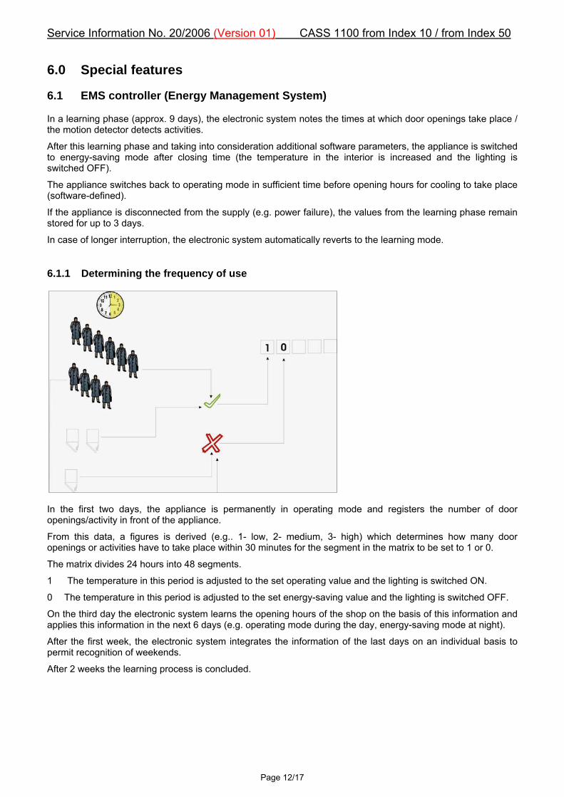
In case of longer interruption, the electronic system automatically reverts to the learning mode. 6.1.1 Determining the frequency of use
In the first two days, the appliance is permanently in operating mode and registers the number of door openings/activity in front of the appliance.
From this data, a figures is derived (e.g.. 1- low, 2- medium, 3- high) which determines how many door openings or activities have to take place within 30 minutes for the segment in the matrix to be set to 1 or 0.
The matrix divides 24 hours into 48 segments.
1 The temperature in this period is adjusted to the set operating value and the lighting is switched ON.
0 The temperature in this period is adjusted to the set energy-saving value and the lighting is switched OFF.
On the third day the electronic system learns the opening hours of the shop on the basis of this information and applies this information in the next 6 days (e.g. operating mode during the day, energy-saving mode at night).
After the first week, the electronic system integrates the information of the last days on an individual basis to permit recognition of weekends.
After 2 weeks the learning process is concluded.

Service Information No. 20/2006 (Version 01) CASS 1100 from Index 10 / from Index 50
Page 13/17
6.1.2 Creating the matrix
Basic principle of the matrix
Individual adaptability of the matrix:
In order that the contents are sufficiently cooled when the shop opens, cooling to the set operating value commences 240 minutes beforehand.
After closing hours, the set energy-saving value is adopted after 60 minutes and the lighting is switched OFF after a further 30 minutes. 6.1.3 pull-down (= rapid cooling to set operating value)
If the interior temperature rises to +20°C (e.g. during loading), cooling takes place with priority, i.e. the compressor and the interior fan run permanently (even when the door is opened) until the switch-off value is reached (pull-down). Any defrosting phase is suppressed if necessary. 6.1.4 softstart
To reduce current peaks, the electric loads start with delay.
The lighting switches on immediately, the compressor and the two condenser/gas cooler fans start after 30 seconds and the interior fan starts after another 20 seconds. 6.2 Delivery options
• FKDv 3412 including CASS 1100 → FKDv 3412-10 (R134a cassette) → FKDv 3412-50 (CO2 cassette)
• FKDv 3412 solo → FKDvg 3412-90
• CASS 1100 solo → CASSP 1100-10 (R134a) → CASSP 1100-50 (CO2) 6.3 Operating instructions
Operating instructions accompany the FKDv. Operating possibilities of the appliance are not described. The reader is informed that certain kinds of work may be carried out by authorised persons only!

Service Information No. 20/2006 (Version 01) CASS 1100 from Index 10 / from Index 50
Page 14/17
7.0 Replacement of parts
7.1 Cassette disassembly
Mounting bracket: Disconnect power line and 5-pin connector. Disengage the mounting brackets and lower them (retaining lugs lower the cassette). Draw the cassette forwards for removal.
7.2 Changing the electronics and sensor
Electronics + sensor: Remove the right-hand side cover of the cassette. Detach the electronic unit and draw it forwards. The sensor cables are directly connected to the electronics. When changing the air sensor, pay attention to the inner and outer seal.
Fig. 7.1 / 1 Cassette fitted Fig. 7.1 / 2 Retaining lugs
Mounting bracket
Mounting bracket
Retaining lugs
Fig. 7.2 / 1 Fig. 7.2 / 2
Interior sensorInner seal
Outer seal
Electronic

Service Information No. 20/2006 (Version 01) CASS 1100 from Index 10 / from Index 50
Page 15/17
7.3 Changing the interior fan
Interior fan: Detach evaporator cover (some screws are under the seal). In order to undo the fastening screws of the fan, it may be necessary to detach the evaporator.
7.4 Changing the condenser fans
Condenser fans: Undo the screws at all 4 corners and raise the entire upper part at the front. Undo the fastening screws of the fan mount.
Fig. 7.3 / 2 Fig. 7.3 / 1 Electronic unit
Interior fan
Fig. 7.4 / 2 Fig. 7.4 / 1
Fan mount

Service Information No. 20/2006 (Version 01) CASS 1100 from Index 10 / from Index 50
Page 16/17
8.0 Technical data
Crossflow fan: Speed: 2000 rpm. Wattage: 40 W Voltage: 230 V
Condenser fans: Speed: 1800 rpm. Wattage: 2x15 W Voltage: 230 V
Sensor: +20°C 12.8 kOhm
9.0 Checking the cassette
9.1 Checking the electrical components
- Cover blow-out opening with wire grid – otherwise risk of injury by interior fan (Fig. 9.1 /1).
- Connect start device.
Procedure: - Electronic unit first displays the software status and then the actual temperature. - Lighting switches ON (see start device). - 30 seconds later the compressor and two condenser/gas cooler fans switch ON. - 20 seconds later the interior fan switches ON. - Actuate the rotary knob (Fig. 9.1 / 2) on the start device to simulate "Door open". “d0“ on the display. - Pay attention to any unusual noise. 9.2 Visual check
- Take cassette out of service (disconnect power plug).
- Detach side covers and check whether the soldered joints show signs of any leakage (e.g. escaping oil) or whether any other irregularities are evident.
Fig. 9.1 / 1 Fig. 9.1 / 2 Start device
Wire grid
Blow-out opening

Service Information No. 20/2006 (Version 01) CASS 1100 from Index 10 / from Index 50
Page 17/17
10.0 Displays on electronic unit
10.1 Status display
E46 On start-up - software status
7.5 Operating mode – actual temperature
--- Stand-by mode
SP Press set button - set temperature
888 Heating mode – actual temperature too low, i.e. < 0°C (compressor OFF – interior fan ON)
dEF Defrosting phase active
dO Door open
rSF Insufficient cooling, i.e. set operating temperature was not reached after 72 hours continuous compressor operation (compressor switches OFF – message has to be acknowledged)
SLO Undervoltage (compressor switches OFF – switches ON again when voltage is OK)
SHI Overvoltage (compressor switches OFF – switches ON again when voltage is OK)
PF Sensor error (compressor switches OFF)
Red LED for HT Condenser too hot (compressor switches OFF – message has to be acknowledged)
10.2 Readout options (by button combinations)
Press "up" and "down" buttons simultaneously.
The codes and associated values are displayed in alternation.
This mode proceeds automatically and ends as soon as the last value was displayed.
HI → 12.9 Warmest interior temperature
LO → 2.3 Coldest interior temperature
At → 5.6 Average interior temperature
DC → 124 Number of door openings
Cnt → 262 Number of persons who passed by
CC → 182 Number of compressor cycles
CH → 1.3 Operating hours of compressor
AF → 3 Identifier for frequency of use
PEr → OFF Set operating value also in stand-by mode
After power failure only the CH value remains stored.