Embed Size (px)
Citation preview

� �
www.mundoclima.com
Cassette 4 Ways Compact FCU DCService manual
EnglishCL04415 to CL04416
MUCS-W7

Compact Four-way Cassette Type DC FCU
1
Compact 4-way cassette FCU
1. External Appearance .......................................................................................................... 2
2. Features .............................................................................................................................. 2
3. Product lineup .................................................................................................................... 3
4. Accessories ........................................................................................................................ 3
5. Specifications ..................................................................................................................... 5
6. Dimension ........................................................................................................................... 6
7. Wiring Diagrams ................................................................................................................. 7
8. Troubleshooting ................................................................................................................. 8
9. Installation .......................................................................................................................... 9

Compact Four-way Cassette Type DC FCU
2
1. External Appearance
2. Features
Capacity range: 300CFM to 500CFM
Compact design, simple installation and easy maintenance
Round blow air supply enables uniform air flow distribution
Comfortable horizontal air discharge reduces draughts and ceiling soiling
Unique design of the centrifugal fan ensures extra-quiet operation and high efficiency
Wireless remote control with LED display, wired control is optional
Built-in drain water pump with 500mm pumping head
Optional extended drainage pan for protecting your ceiling better
Four speed motor with one reserved for more choice
Fresh air provision makes life healthier and more comfortable
Excellent efficiency
Mundoclima DC FCU adopt the brushless DC motor, the DC motor efficiency is up to 90%. In contrast
with the original FCU. DC FCU power consumption can be reduced by more than 30%.
DC and AC motors power contrastPower Inpu t:W
Air Flow:CFM
200
0
50
100
150
200
300 400 500 600 800 1000 1200
DC moto r
AC moto r

Compact Four-way Cassette Type DC FCU
3
DC brushless motor
The motor adopts fully enclosed structure design, it is energy-saving , of high operating efficiency and
durable motor. The motor bearing can operate 80,000 hours continuously, and easy for maintenance.
Low noise
Advanced 3-D spiral fan design reduces air resistance and operating sound. The motor bearing
with unique design makes less operation vibration.
3. Product lineup
Type 14 16
Compact 4-way cassette (MUCS-W7) ● ●
4. Accessories
Standard accessories Accessory name Qty. Shape Usage
Owner’s & installation manual 1 / Installation guide
Installation paper board 1
Tubing& Fittings 2
Soundproof/ insulation sheath
Drainpipe Fittings
1
Out-let pipe
1
Out-let pipe clasp
5 Tightening band
Remote controller& Its Frame
1
Remote controller
R05/BGE-20
1
Frame
2
Mounting screw(ST2.9x10-C-H)
2
Alkaline dry batteries
Remote controller manual 1
2

Compact Four-way Cassette Type DC FCU
4
Optional accessories Accessory name Qty. Shape Usage
Wired controller
KJR-29B 1
Wired control
Wired controller
KJR-12B/D 1
Wired control
Central controller
CCM03 1
Central control
3-way valve 1
(CL92869)
(CL92871)
(CL92905)
Central control Central controller
CCM30
(CL92911)
(CO05506 + CO05509)3-way valve

Compact Four-way Cassette Type DC FCU
5
5. Specifications Model
Air flow H/M/L m
3/h 717/502/359 785/550/393
H/M/L CFM 422/296/211 462/324/231
Cooling
Capacity H/M/L kW 3.93/3.07/2.48 4.24/3.31/2.67
Water flow rate H l/h 676 729
Water pressure drop H/M/L kPa 12.0 9.4
Heating 50℃ Capacity H/M/L kW 5.34/4/3.15 5.77/4.33/3.4
Water pressure drop H kPa 10.6 9.4
Heating 70℃ Capacity H/M/L 8.34/6.26/5.16 9/6.76/5.56
Water pressure drop H kPa 11.9 10.5
Power supply V/Ph/Hz 220-240/1/50
Power input H W 27 32
Sound pressure level H/M/L dB(A) 44.8/36.2/28.8 46.6/37.9/30.3
Fan motor
Type DC motor
Quantity 1
Brand Panasonic Panasonic
Model WZDK37-38G WZDK37-38G
Fan Type Centrifugal, forward-curved Blades
Quantity 1
Coil
Row 2
Max. Working pressure MPa 1.6
Coil length x height mm 1315 x210
Fin spacing mm 1.3
Fin type Hydrophilic aluminium
Number of circuits 6 7
Diameter mm Φ7
Panel
Dimensions W×H×D mm 647×50×647
Packing W×H×D mm 715×123×715
Net weight kg 2.5
Gross weight kg 4.5
Body
Dimensions W×H×D mm 575×261×575
Packing W×H×D mm 655×290×655
Net weight kg 16.5
Gross weight kg 21.5
Pipe connection Water inlet/outlet pipe Inch G3/4
Drain pipe mm ODΦ25
Note:
1. The data is the performance in high speed with relevant static pressure.
2. Cooling Conditions: Entering Water 7°C, Temperature Rise 5°C, Entering Air Temperature 27°C DB,19°CWB.
Heating Conditions: Entering Water 50°C, enter air temperature 20°C, the same water flow as the cooling conditions.
Entering water 70°C, enter air temperature 20°C,△T water 10°C.
3. Noise is tested in full-anechoic test room.
MUCS-14-W7 MUCS-16-W7

Compact Four-way Cassette Type DC FCU
6
6. Dimension
H(mm) 50

Compact Four-way Cassette Type DC FCU
7
7. Wiring Diagrams
MUCS-14-W7
MUCS-16-W7
(Reserved)

Compact Four-way Cassette Type DC FCU
8
8. Troubleshooting Troubles and causes of air conditioner If one of the following malfunctions occur, stop operation, shut off the power, and contact with your dealer.
The operation lamp is flashing rapidly (five times per second),
you disconnect the unit with the power and then connect the unit with the power again after two or three
minutes but the lamps still flash.
Switch operations are erratic.
The fuse is blown frequently or the circuit breaker is tripped frequently.
Foreign matter or water has fallen inside the air conditioner.
Water leaks from the indoor unit.
Other malfunctions.
If the system does not properly operate except the above mentioned cases or the above mentioned
malfunctions is evident, investigate the system according to the following procedures.
Solution
Clean the heat exchanger.
Clean the air filter.
Eliminate all dirties and make air
smooth.
Close doors and windows.
Make curtains in order to shelter from
sunshine.
Reduce heat source.
AC cooling capacity reduces (normal).
Check leakage .
Symptoms Causes
Unit does not start
Air flowing normally butcompletely can't cooling
Units start or stop frequently
Low cooling effect
Low heating effect
Power failure.
Power switch is off.
Fuse of power switch may have burned.
Batteries of remote controller exhausted
or other problem of controller.
Temperature is not setted correctly.�
Air or no concreting gas in the watering
circuit.
three-way valve is malfunction.
Voltage is too high or too low.
System circuit is blocked.
Temperature is not setted correctly.
Indoor unit heat exchanger is dirty.
The air filter is dirty.
Inlet/outlet of indoor units is blocked.
Doors and windows are open
Sunlight directly shine.
Too much heat resource.
Leakage of water .
Wait for the comeback of power.
Switch on the power.
Replace the fuse.
Replace the batteries or check the
controller.
Set the temperature properly.
Vacuum .
Maintenance or change three-way
valve.
Install manostat.
Find reasons and solution.
Use heating device.
Close doors and windows.
Check leakage.
Doors and windows not completely
closed.
Leakage of water.
×
NO. Malfunction Operation Timer Defrost Alarm
1
2
3
4
5
Room temperature sensor checking channel is abnormal
Evaporator sensor checking channel is abnormal
EEPROM malfunction
Water-level switch malfunction
×
× ×
×
×
× ×
×
× × ☆
☆
× × × ☆
☆
(× Extinguish,☆ Flash at 5Hz)
☆ ☆
ON/OFF switch66
Fan failure ☆☆ × ×

Compact Four-way Cassette Type DC FCU
9
9. Installation 9.1 Installation space
The indoor unit should be installed in a location that meets the following requirements:
There is enough room for installation and maintenance.
The ceiling is horizontal, and its structure can endure the weight of the indoor unit.
The outlet and the inlet are not impeded, and the influence of external air is the least.
The air flow can reach throughout the room.
The connecting water pipe and drainpipe could be extracted out easily.
There is no direct radiation from heaters.
Caution:
Keep indoor unit, outdoor unit, power supply wiring and transmission wiring at least 1 meter away from
televisions and radios. This is to prevent image interference and noise in those electrical appliances. (Noise
may be generated depending on the conditions under which the electric wave is generated, even if 1 meter
is kept.)
9.2 Install the main body
A. The existing ceiling (to be horizontal)
a. Cut a quadrangular hole of 880×880mm in the ceiling according to the shape of the installation paper
board.
The center of the hole should be at the same position of that of the air conditioner body.
Determine the lengths and outlets of the connecting pipe, drain pipe and cables.
To balance the ceiling and to avoid vibration, please enforce the ceiling when necessary.
b. Select the position of installation hooks according to the hook holes on the installation board.
Drill four holes of Ø12mm, 50~55mm deep at the selected positions on the ceiling. Then embed the expansible hooks (fittings).
Face the concave side of the installation hooks toward the expansible hooks. Determine the length of the installation hooks from the height of ceiling, and then cut off the unnecessary part.
If the ceiling is extremely high, please determine the length of the installation hook according to facts.
c. Adjust the hexangular nuts on the four installation hooks evenly, to ensure the balance of the body.
If the drainpipe is awry, leakage will be caused by the malfunction of the water-level switch.
Adjust the position to ensure the gaps between the body and the four sides of ceiling are even. The body's lower part should sink into the ceiling for 10~12 mm.
In general, L is half of the screw length of the installation hook.
Locate the air conditioner firmly by wrenching the nuts after having adjusted the body's position well.

Compact Four-way Cassette Type DC FCU
10
B. New built houses and ceilings
a. In the case of new built house, the hook can be embedded in advance (refer to the A.b mentioned
above). But it should be strong enough to bear the indoor unit and will not become loose because of
concrete shrinking.
b. After installing the body, please fasten the installation paper board onto the air conditioner with bolts
(M6*12) to determine in advance the sizes and positions of the hole opening on ceiling.
Please first guarantee the flatness and horizontal of ceiling when installing it.
Refer to the A.a mentioned above for others.
c. Refer to the A.c mentioned above for installation.
d. Remove the installation paper board.
Caution:
After installing the body, the four bolts(M6x12) must be fastened to the air conditioner onto ensure the body
is grounded well.
9.3 Install the Panel
Caution:
Never put the panel face down on floor or against the wall, or on bulgy objects.
Never crash or strike it.
(1) Remove the air inlet grill.
a. Slide two grid switches toward the middle at the same time, and then pull them up.
b. Draw the grid up to an angle of about 45o, and remove it.

Compact Four-way Cassette Type DC FCU
11
(2) Remove the installation covers at the four corners.
Wrench off the bolts, loose the rope of the installation covers, and remove them.
(3) Install the panel
a. Align the swing motor on the panel to the tubing joints of the body properly.
b. Fix hooks of the panel at swing motor and its opposite sides to the hooks of corresponding water
receiver. Then hang the other two panel hooks onto corresponding hangers of the body.
Cautions
Do not coil the wiring of the swing motor into the seal sponge.
c. Adjust the four panel hook screws to keep the panel horizontal, and screw them up to the ceiling evenly.
d. Regulate the panel in the direction of the arrow slightly to fit the panel's center to the center of the
ceiling's opening. Guarantee that hooks of four corners are fixed well.
e. Keep fastening the screws under the panel hooks, until the thickness of the sponge between the body
and the panel's outlet has been reduced to about 4~6mm. The edge of the panel should contact with the
ceiling well.
If the gap between the panel and ceiling still exists after fastening the screws, the height of the indoor unit
should be modified again.
You can modify the height of the indoor unit through the openings on the panel's four corners; if the lift of the
indoor unit and the drainpipe is not influenced.
(4) Hang the air-in grid to the panel, and then connect the lead terminator of the swing motor and that of the control box with corresponding terminators on the body respectively.
(5) Relocate the air-in grid in the procedure of reversed order.
(6) Relocate the installation cover.
a. Fasten the rope of installation cover on the bolt of the installation cover. (Refer to chart 16-left)
b. Press the installation cover into the panel slightly. (Refer to chart 16-right)
9.4 Connect the Drain Pipe
9.4.1 Install the drainpipe
You can use a polyethylene tube as the drainpipe (out-dia. 37~39mm, in-dia. 32mm). It could be bought at local market or from your dealer.
Set the mouth of the drainpipe onto the root of the body's pump-pipe, and clip the drainpipe and the out-let pipe sheath (fittings) together firmly with the out-let pipe clasp (fitting).

Compact Four-way Cassette Type DC FCU
12
Cautions:
Use your strength carefully to prevent the pump-pipe from breaking.
The body's pump pipe and the drainpipe (especially the indoor part) should be covered evenly with the out-let pipe sheath (fittings) and be bound tightly with the constrictor to prevent condensation caused by entered air.
To prevent water from flowing backwards into the air conditioner while the air conditioner stops, please lean the drainpipe down toward outdoor (outlet-side) at a degree of over 1/50. And please avoid any bulge or water deposit. (Refer to the following)
Do not drag the drainpipe violently when connecting to prevent the body from being pulled.
Meanwhile, one support-point should be set every 1~1.5m to prevent the drainpipe from yielding. Or
you can tie the drainpipe with the connecting pipe to fix it.
In the case of prolonged drainpipe, you had better tighten its indoor part with a protection tube to prevent it from loosing.
If the outlet of the drainpipe is higher than the body's pump joint, the pipe should be arranged as vertically as possible. And the lift distance must be less than 500mm, otherwise the water will overflow when the air conditioner stops.
The end of the drainpipe should be over 50mm higher than the ground or the bottom of the drainage chute, and do not immerse it in water. If you discharge the water directly into sewage is sure to make a U-form aqua seal by bending the pipe up to prevent the smelly gas entering the house through the drain pipe.
Cautions:
All the joints of the drain system must be sealed to prevent water leakage.
1. All field piping must be provided by a licensed water technician and must comply with the relevant local and national codes.
2. Do not let air, dust, or other impurities fall in the pipe system during the time of installation.

Compact Four-way Cassette Type DC FCU
13
3. The connecting pipe should not be installed until the indoor and outdoor units have been fixed already.
4. Keep the connecting pipe dry, and do not let moisture in during installation.
Note:
All the pictures in this manual are for explanation purpose only. They may be slightly different from the air
conditioner you purchased (depend on model).The actual shape shall prevail.
9.4.2 Drainage test
Check whether the drainpipe is unhindered.
New built house should have this test done before paving the ceiling.
1. Remove the test cover, and stow water of about 2000ml to the water receiver through the stow tube.
2. Turn on the power, and operate the air conditioner under the "COOLING" mode. Listen to the sound of
the drain pump. Check whether the water is discharged well (a lag of 1min is allowed before discharging,
according to the length of the drain pipe), and check whether water leaks from the joints.
Cautions: If there is any malfunction, please resolve it immediately.
3. Stop the air conditioner for there minutes, check if everything is ok. If the drain hose is located
unreasonable, water overflow will cause the Alarm indicator lamp flashing (For both cooling and heating
type or cooling only type), even the water leak out from the water receiver.
4. Check the drain pump whether drain water immediately when alarm sound for the high water lever. If
the water lever can't come down below to the limited water lever, the air conditioner will stop. Restart it
until turn off the power and drain off all the water.
5. Turn off the power, drain the water away.
The drain plug is used to empty the water-receiver for maintenance of the air conditioner. Please stuff it imposition at all times during operation to avoid leakage.
9.5 Cleaning the air filter The air filter can prevent the dust or other particulate from going inside. In case of blockage of the filter,
the working efficiency of the air conditioner may greatly decrease.
Therefore, the filter must be cleaned once two weeks during long time frequent.
If the accumulated dust is too heavy to be cleaned, please replace the filter with a new one(replaceable
air filter is an optional filter).
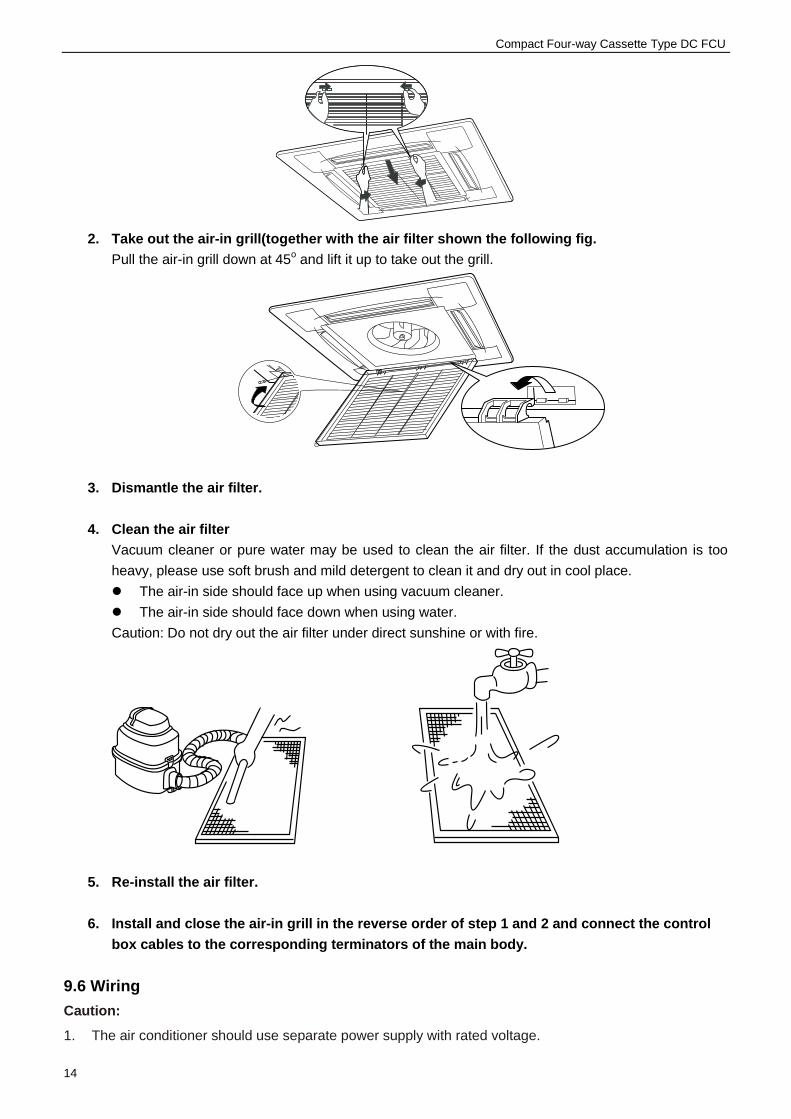
1. Open the air-in grill Push the grill switches towards the middle simultaneously as the following fig. Then pull down the
air-in grill.
The control box cables, which are originally connected with the main body electrical terminators
must be pulled off before doing as indicated above.
Compact Four-way Cassette Type DC FCU
14
2. Take out the air-in grill(together with the air filter shown the following fig.
Pull the air-in grill down at 45o and lift it up to take out the grill.
3. Dismantle the air filter.
4. Clean the air filter Vacuum cleaner or pure water may be used to clean the air filter. If the dust accumulation is too
heavy, please use soft brush and mild detergent to clean it and dry out in cool place.
The air-in side should face up when using vacuum cleaner.
The air-in side should face down when using water.
Caution: Do not dry out the air filter under direct sunshine or with fire.
5. Re-install the air filter.
6. Install and close the air-in grill in the reverse order of step 1 and 2 and connect the control
box cables to the corresponding terminators of the main body.
9.6 Wiring
Caution:
1. The air conditioner should use separate power supply with rated voltage.

Compact Four-way Cassette Type DC FCU
15
2. The external power supply to the air conditioner should have ground wiring, which is linked to the
ground wiring of the indoor and outdoor unit.
3. The wiring work should be done by qualified persons according to circuit drawing.
4. An all-pole disconnection switch having a contract separation of at least 3mm in a pole should be
connected in fixed wiring.
5. Be sure to locate the power wiring and the signal wiring well to avoid cross-disturbance.
6. Do not turn on the power until you have checked carefully after wiring.
Note:
Remark per EMC Directive 89/336/EEC to prevent flicker impressions during the start of the compressor
(technical process), following installation conditions do apply.
1. The power connection for the air conditioner has to be done at the main power distribution. The distribution has to be of a low impedance, normally the required impedance reaches at a 32A fusing point.
2. No other equipment has to be connected with this power line.
3. For detailed installation acceptance please refer to your power supplier, if restrictions do apply for products like washing machines, air conditioners or electrical ovens.
4. For power details of the air conditioner refer to the rating plate of the product.
5. For any question contact your local dealer.
9.6.1 Connect the cable
Dissemble the bolts from the cover.(If there isn't a cover on the outdoor unit, disassemble the bolts from the maintenance board, and pull it in the direction of the arrow to remove the protection board.)
Connect the connective cables to the terminals as identified with their respective matched numbers on the terminal block of indoor and outdoor units.
Re-install the cover or the protection board.
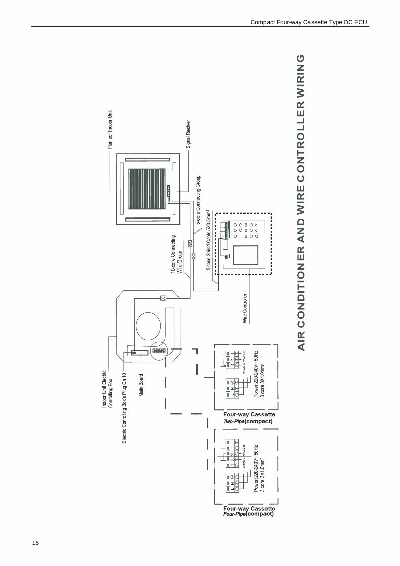
9.6.2 Wiring figure
Compact Four-way Cassette Type DC FCU
16

Compact Four-way Cassette Type DC FCU
17
9.7 Test operation
(1) The test operation must be carried out after the entire installation has been completed. (2) Please confirm the following points before the test operation. The indoor unit and outdoor unit are installed properly.
Tubing and wiring are correctly completed.
The refrigerant pipe system is leakage-checked.
The drainage is unimpeded.
The ground wiring is connected correctly.
The length of the tubing and the added stow capacity of the refrigerant have been recorded.
The power voltage fits the rated voltage of the air conditioner.
There is no obstacle at the outlet and inlet of the outdoor and indoor units.
The gas-side and liquid-side stop values are both opened.
The air conditioner is pre-heated by turning on the power.
(3) According to the user's requirement, install the remote controller when the remote controller's signal can reach the indoor unit smoothly. (4) Test operation Set the air conditioner under the mode of "COOLING" with the remote controller, and check the following
points.
● Whether the switch on the remote controller works well.
● Whether the buttons on the remote controller works well.
● Whether the air flow louver moves normally.
● Whether the room temperature is adjusted well.
● Whether the indicator lights normally.
● Whether the temporary buttons works well.
● Whether the drainage is normal.
● Whether there is vibration or abnormal noise during operation.
● Whether the air conditioner heats well in the case of the HEATING/COOLING type.
9.6.3 Network address set Every air-conditioner in network has only one network address to distinguish each other. Address code of
air-conditioner in LAN is set by code switch on Network Interface Module (NIM), and the set range is 0-63.
S1 ENC1

ASK FOR MORE INFORMATION
Phone: (+34) 93 446 27 81eMail: [email protected]
TECHNICAL ASSISTANCE
Phone: (+34) 93 652 53 57
www.mundoclima.com