Embed Size (px)
DESCRIPTION
ABCommunication Interface Module
Citation preview
Communication Interface Module
Installation Data
Cat. No. 1784-KT/B
The 1784-KT/B Communication Interface Module allows personalcomputers, workstations or terminals to communicate with Allen-Bradleyprocessors and controllers, either through direct connections or over DataHighway Plus networks. For information about using the 1784-KT/B witha specific device, see the device’s user documentation.
ATTENTION: The following provides information forAllen-Bradley Industrial Computer and Communication Group(ICCG) products that have been verified to meet theElectromagnetic Interference (EMI) requirements of the FederalCommunication Commission (FCC) and the CanadianDepartment of Communications for use in a commercialenvironment:
This device complies with Part 15 of the FCC rules. Operationis subject to the following two conditions: (1) this device maynot cause harmful interference, and (2) this device must acceptany interference received, including interference that may causeundesired operation.
ATTENTION: This digital apparatus does not exceed theClass A limits for radio noise emissions from digital apparatusset out in the Radio Interference Regulations of the CanadianDepartment of Communications.
Le présent appareil numérique n’émet pas de bruitsradioélectriques dépassant les limites applicables aux appareilsnumériques de la class A prescrites dans le Règlement sur lebrouillage radioélectrique édicté par le ministère desCommunications du Canada.
Introducing the 1784�KT/BCommunication InterfaceModule
Communication Interface ModuleCat. No. 1784�KT/B
Installation Data
2
We will refer to the 1784-KT/B Communication Interface Module assimply the 1784-KT throughout this document.
This document contains the following sections:
Introducing the 1784-KT Communication Interface Module
Important User Information
Features of the 1784-KT
Compatibility
How the 1784-KT Operates
Handling the 1784-KT Module
1784-KT Configuration Information
Installing the 1784-KT into a Computer
Connecting Your 1784-KT
Ordering Information
The Loopback Test Plug
System Memory and Interrupts
Specifications
Because of the variety of uses for products described in this publication,those responsible for the application and use of this control equipmentmust satisfy themselves that all necessary steps have been taken to assurethat each application and use meets all performance and safetyrequirements, including any applicable laws, regulations, codes andstandards.
The illustrations, charts, sample programs and layout examples shown inthis guide are intended solely for purposes of example. Since there aremany variables and requirements associated with any particularinstallation, Allen-Bradley does not assume responsibility or liability (toinclude intellectual property liability) for actual use based upon theexamples shown in this publication.
Allen-Bradley publication SGI-1.1, “Safety Guidelines for the Application,Installation and Maintenance of Solid State Control” (available from yourlocal Allen-Bradley office) describes some important differences betweensolid-state equipment and electromechanical devices which should betaken into consideration when applying products such as those described inthis publication.
Reproduction of the contents of this copyrighted publication, in whole orin part, without written permission of Allen-Bradley Company, Inc. isprohibited.
What This DocumentContains
Important User Information
Communication Interface ModuleCat. No. 1784�KT/B
Installation Data
3
ATTENTION: With any complex communication system youneed to identify potential application-related communicationproblems and make provisions in the system design to preventhazardous or undesired consequences if a problem occurs.These problems include, but are not necessarily limited to, thepossibility of:
unexpected loss of communicationerroneous or incomplete data being supplied to the networkand passed on to your application
Your 1784-KT Communication Interface Module is an ISA half-size 8-bitcard that can be inserted into any 8- or 16-bit ISA expansion slot. The1784-KT provides the following features:
Makes your personal computer an active node on Data Highway Plusnetworks
Increases application response time by removing the RS-232 bottleneck
Provides single cable connection to a PLC-2 , PLC- 3 , or PLC-5family programmable controller
Is address selectable; may be used with other option boards installed inyour personal computer
When combined with 6001-F1E software or INTERCHANGEsoftware, allows you to create your own custom interface to DataHighway Plus networks
Supported by the following software:
- 6001-FIE software- 6200 software- INTERCHANGE software- Advisor PC (series E or later)- ControlView software
Features of the 1784�KT
Communication Interface ModuleCat. No. 1784�KT/B
Installation Data
4
Operation of the 1784-KT has been verified with the following:
Company: Model:
Allen�Bradley • 1771 Information Processor(1771�DSX2) (requires KT ExpanderModule 1771�DXKT)
• 1784�T35 Industrial Terminal
• 1784�T50 Industrial Terminal
• Allen�Bradley 6121
• Allen�Bradley 6122
• T53 Industrial Programming Terminal6160�T53
• T60 Industrial Workstation6160�PCD2, �PCN2, �PCD4, �PCN4
• T70 Industrial Workstation6170 series
IBM • IBM PC�XT/AT
Compaq • Compaq Portable 286
• Compaq Portable II
• Compaq Portable III
• Compaq Deskpro 286
• Compaq Deskpro 386
Dell • Dell 316 386SX
Samsung • Samsung S550
• Samsung 386
Hewlett�Packard • HP 9000 /700 series
The 1784-KT allows you to:
directly connect to:
- PLC-2 processors- PLC-3 processors
communicate with nodes on Data Highway Plus networks (includingPLC-5 and PLC-5/250 processors)
communicate with SLC processors (requires 1785-KA5 bridge)
The 1784-KT performs data transmission, management, and local DataHighway Plus diagnostics. The interface to the host processor is through aboard-resident dual-port memory that passes preformatted Data HighwayPlus packets.
When the host powers up and downloads module code, it runs diagnosticsto verify the 1784-KT module’s operation. Allen-Bradley interfacesoftware (including 6001-F1E, 6200, Interchange, Advisor PC, andControlView) manages data transmission and reception through theboard-resident dual-port memory.
Compatibility
How the 1784�KT Operates
Communication Interface ModuleCat. No. 1784�KT/B
Installation Data
5
The 1784-KT utilizes CMOS technology, which is highly sensitive toElectro Static Discharge (ESD). ESD may be present whenever you arehandling the 1784-KT. Handling the 1784-KT without any ESD protectioncan cause internal circuit damage that may not be apparent duringinstallation or initial use. A grounding wrist strap has been shipped withthe 1784-KT to be worn during the installation procedure. Instructions foruse of the strap are found on the back of its package.
ATTENTION: The following is a list of precautions to guardagainst ESD damage:
1. Before handling the module, be sure to wear the providedstatic strap and touch a grounded object to discharge anybuilt-up static charge.
2. When selecting your memory and interrupt options, avoidtouching other components on the 1784-KT.
3. Avoid touching the back plane connector or interfaceconnector pins located on the 1784-KT.
4. If the module is not in use, store the 1784-KT in the staticbag that the module was shipped in.
Important: Do not change the (factory set) configuration settings untilyou have read this section.
The 1784-KT comes with preset memory location (D400) and no interrupt.This may not be appropriate for your application. See the section“Installing the 1784-KT into a Computer”, which begins on page 6, forinformation on memory locations and interrupt settings.
ATTENTION: When selecting configuration settings, checkfor conflicts with other interface cards and system memory. Ifthere is a conflict, the system will not operate properly.
Handling the 1784�KT Module
1784�KT ConfigurationInformation
Communication Interface ModuleCat. No. 1784�KT/B
Installation Data
6
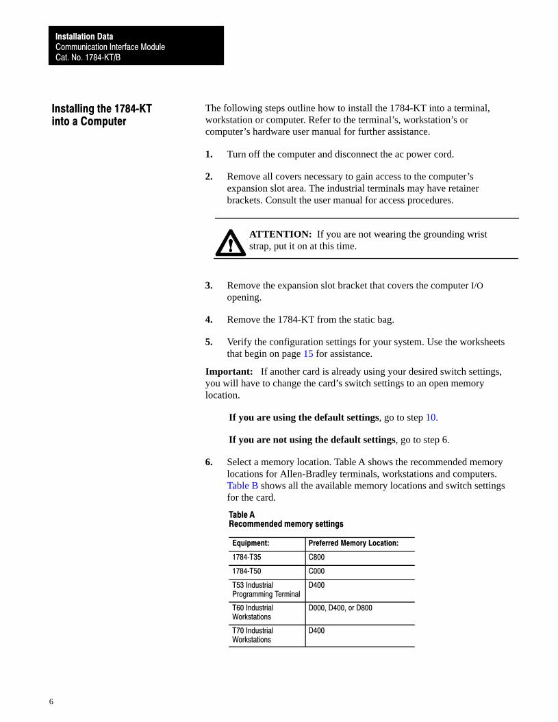
The following steps outline how to install the 1784-KT into a terminal,workstation or computer. Refer to the terminal’s, workstation’s orcomputer’s hardware user manual for further assistance.
1. Turn off the computer and disconnect the ac power cord.
2. Remove all covers necessary to gain access to the computer’sexpansion slot area. The industrial terminals may have retainerbrackets. Consult the user manual for access procedures.
ATTENTION: If you are not wearing the grounding wriststrap, put it on at this time.
3. Remove the expansion slot bracket that covers the computer I/Oopening.
4. Remove the 1784-KT from the static bag.
5. Verify the configuration settings for your system. Use the worksheetsthat begin on page 15 for assistance.
Important: If another card is already using your desired switch settings,you will have to change the card’s switch settings to an open memorylocation.
If you are using the default settings, go to step 10.
If you are not using the default settings, go to step 6.
6. Select a memory location. Table A shows the recommended memorylocations for Allen-Bradley terminals, workstations and computers.Table B shows all the available memory locations and switch settingsfor the card.
Table ARecommended memory settings
Equipment: Preferred Memory Location:
1784�T35 C800
1784�T50 C000
T53 IndustrialProgramming Terminal
D400
T60 IndustrialWorkstations
D000, D400, or D800
T70 IndustrialWorkstations
D400
Installing the 1784�KTinto a Computer
Communication Interface ModuleCat. No. 1784�KT/B
Installation Data
7
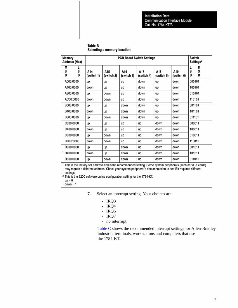
Table BSelecting a memory location
MemoryAddress (Hex)
PCB Board Switch Settings Switch Settings2
M L S S B B
A14(switch 1)
A15(switch 2)
A16(switch 3)
A17(switch 4)
A18(switch 5)
A19(switch 6)
L MS SB B
A000:0000 up up up down up down 000101
A400:0000 down up up down up down 100101
A800:0000 up down up down up down 010101
AC00:0000 down down up down up down 110101
B000:0000 up up down down up down 001101
B400:0000 down up down down up down 101101
B800:0000 up down down down up down 011101
C000:0000 up up up up down down 000011
C400:0000 down up up up down down 100011
C800:0000 up down up up down down 010011
CC00:0000 down down up up down down 110011
D000:0000 up up down up down down 001011
1 D400:0000 down up down up down down 101011
D800:0000 up down down up down down 011011
1 This is the factory�set address and is the recommended setting. Some system peripherals (such as VGA cards) may require a different address. Check your system peripheral's documentation to see if it requires different
settings. 2 This is the 6200 software online configuration setting for the 1784�KT.
up = 0down = 1
7. Select an interrupt setting. Your choices are:
- IRQ3- IRQ4- IRQ5- IRQ7- no interrupt
Table C shows the recommended interrupt settings for Allen-Bradleyindustrial terminals, workstations and computers that usethe 1784-KT.
Communication Interface ModuleCat. No. 1784�KT/B
Installation Data
8
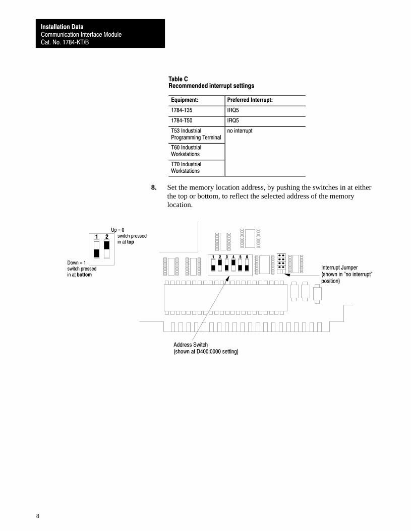
Table CRecommended interrupt settings
Equipment: Preferred Interrupt:
1784�T35 IRQ5
1784�T50 IRQ5
T53 IndustrialProgramming Terminal
no interrupt
T60 IndustrialWorkstations
T70 IndustrialWorkstations
8. Set the memory location address, by pushing the switches in at eitherthe top or bottom, to reflect the selected address of the memorylocation.
Interrupt Jumper(shown in �no interrupt"position)
Address Switch(shown at D400:0000 setting)
Up = 0switch pressedin at top
Down = 1switch pressedin at bottom
Communication Interface ModuleCat. No. 1784�KT/B
Installation Data
9
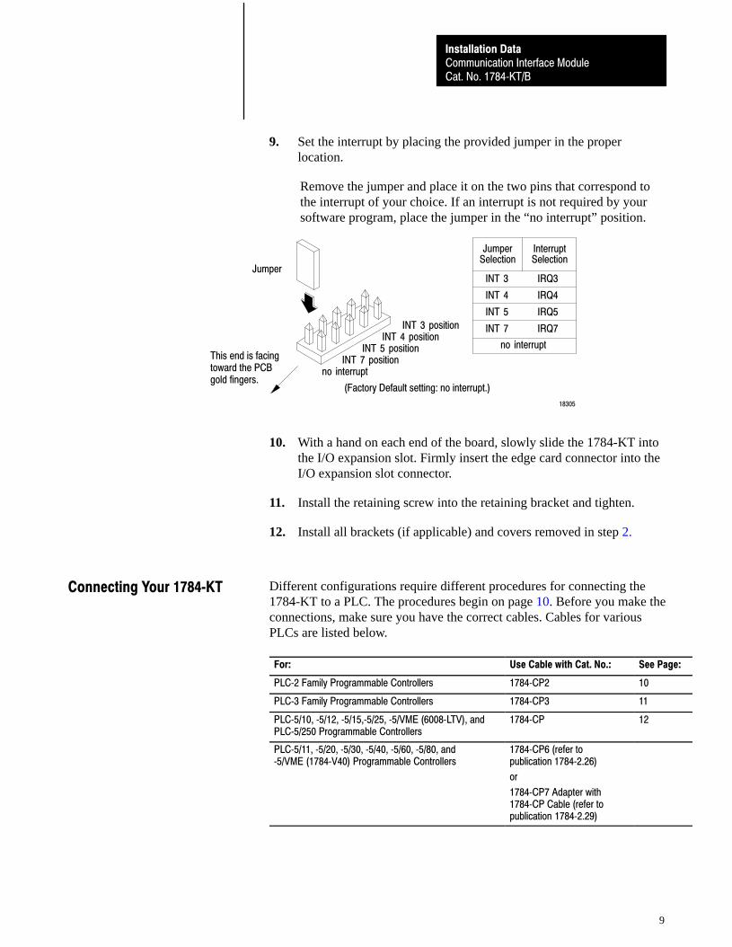
9. Set the interrupt by placing the provided jumper in the properlocation.
Remove the jumper and place it on the two pins that correspond tothe interrupt of your choice. If an interrupt is not required by yoursoftware program, place the jumper in the “no interrupt” position.
Jumper
INT 3 positionINT 4 position
INT 5 positionINT 7 position
no interrupt
JumperSelection
INT 3
INT 4
INT 5
INT 7
InterruptSelection
IRQ3
IRQ4
IRQ5
IRQ7
no interrupt
18305
(Factory Default setting: no interrupt.)
This end is facing toward the PCBgold fingers.
10. With a hand on each end of the board, slowly slide the 1784-KT intothe I/O expansion slot. Firmly insert the edge card connector into theI/O expansion slot connector.
11. Install the retaining screw into the retaining bracket and tighten.
12. Install all brackets (if applicable) and covers removed in step 2.
Different configurations require different procedures for connecting the1784-KT to a PLC. The procedures begin on page 10. Before you make theconnections, make sure you have the correct cables. Cables for variousPLCs are listed below.
For: Use Cable with Cat. No.: See Page:
PLC�2 Family Programmable Controllers 1784�CP2 10
PLC�3 Family Programmable Controllers 1784�CP3 11
PLC�5/10, �5/12, �5/15,�5/25, �5/VME (6008�LTV), andPLC�5/250 Programmable Controllers
1784�CP 12
PLC�5/11, �5/20, �5/30, �5/40, �5/60, �5/80, and�5/VME (1784�V40) Programmable Controllers
1784�CP6 (refer topublication 1784�2.26)
or
1784�CP7 Adapter with1784�CP Cable (refer topublication 1784�2.29)
Connecting Your 1784�KT
Communication Interface ModuleCat. No. 1784�KT/B
Installation Data
10
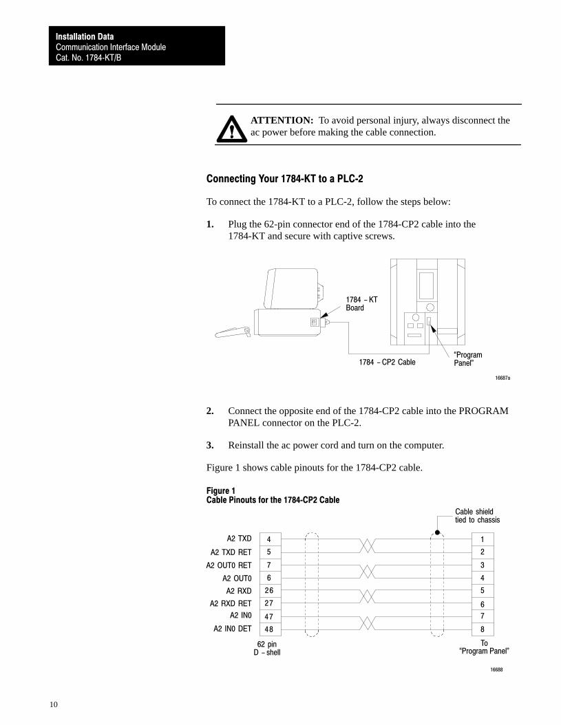
ATTENTION: To avoid personal injury, always disconnect theac power before making the cable connection.
Connecting Your 1784�KT to a PLC�2
To connect the 1784-KT to a PLC-2, follow the steps below:
1. Plug the 62-pin connector end of the 1784-CP2 cable into the1784-KT and secure with captive screws.
1784 - KTBoard
�ProgramPanel"1784 - CP2 Cable
16687a
2. Connect the opposite end of the 1784-CP2 cable into the PROGRAMPANEL connector on the PLC-2.
3. Reinstall the ac power cord and turn on the computer.
Figure 1 shows cable pinouts for the 1784-CP2 cable.
Figure 1Cable Pinouts for the 1784�CP2 Cable
4
5
6
48
7
27
26
1
2
3
4
7
8
A2 TXD
A2 TXD RET
A2 OUT0 RET
A2 OUT0
A2 RXD RET
A2 IN0 DET
A2 RXD
47
6
5
A2 IN0
Cable shieldtied to chassis
62 pinD - shell
16688
To�Program Panel"
Communication Interface ModuleCat. No. 1784�KT/B
Installation Data
11
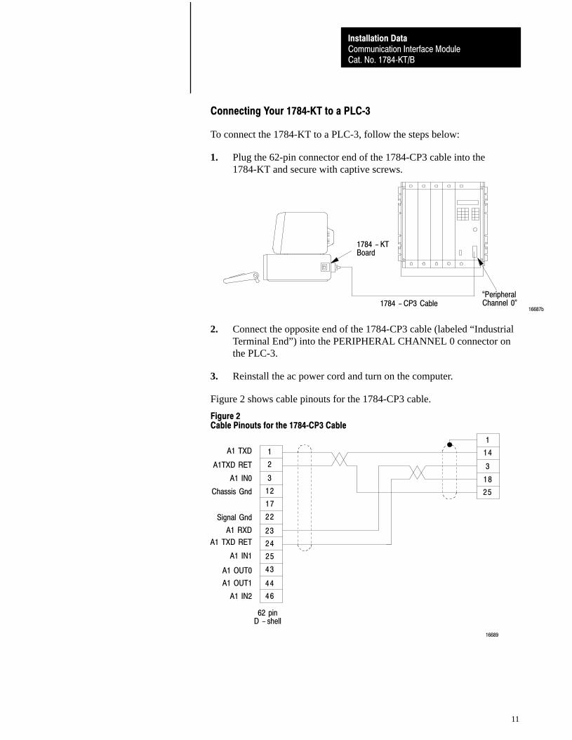
Connecting Your 1784�KT to a PLC�3
To connect the 1784-KT to a PLC-3, follow the steps below:
1. Plug the 62-pin connector end of the 1784-CP3 cable into the1784-KT and secure with captive screws.
1784 - KTBoard
�PeripheralChannel 0"1784 - CP3 Cable
16687b
2. Connect the opposite end of the 1784-CP3 cable (labeled “IndustrialTerminal End”) into the PERIPHERAL CHANNEL 0 connector onthe PLC-3.
3. Reinstall the ac power cord and turn on the computer.
Figure 2 shows cable pinouts for the 1784-CP3 cable.
Figure 2Cable Pinouts for the 1784�CP3 Cable
1
2
12
24
3
22
17
1
14
3
18
A1 TXD
A1TXD RET
A1 IN0
Chassis Gnd
A1 RXD
A1 IN1
Signal Gnd
23
25
A1 TXD RET
62 pinD - shell
46
43
25
44
A1 OUT0
A1 OUT1
A1 IN2
16689
Communication Interface ModuleCat. No. 1784�KT/B
Installation Data
12
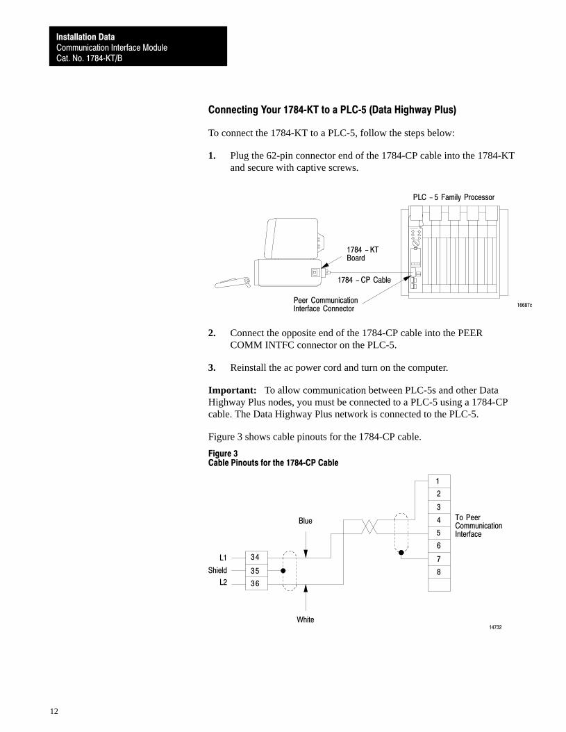
Connecting Your 1784�KT to a PLC�5 (Data Highway Plus)
To connect the 1784-KT to a PLC-5, follow the steps below:
1. Plug the 62-pin connector end of the 1784-CP cable into the 1784-KTand secure with captive screws.
1784 - KTBoard
Peer CommunicationInterface Connector
1784 - CP Cable
PLC - 5 Family Processor
16687c
2. Connect the opposite end of the 1784-CP cable into the PEERCOMM INTFC connector on the PLC-5.
3. Reinstall the ac power cord and turn on the computer.
Important: To allow communication between PLC-5s and other DataHighway Plus nodes, you must be connected to a PLC-5 using a 1784-CPcable. The Data Highway Plus network is connected to the PLC-5.
Figure 3 shows cable pinouts for the 1784-CP cable.
Figure 3Cable Pinouts for the 1784�CP Cable
36
34
1
2
3
4
Shield
L1
35
5
L2
6
7
8
To PeerCommunicationInterface
White
Blue
14732
Communication Interface ModuleCat. No. 1784�KT/B
Installation Data
13
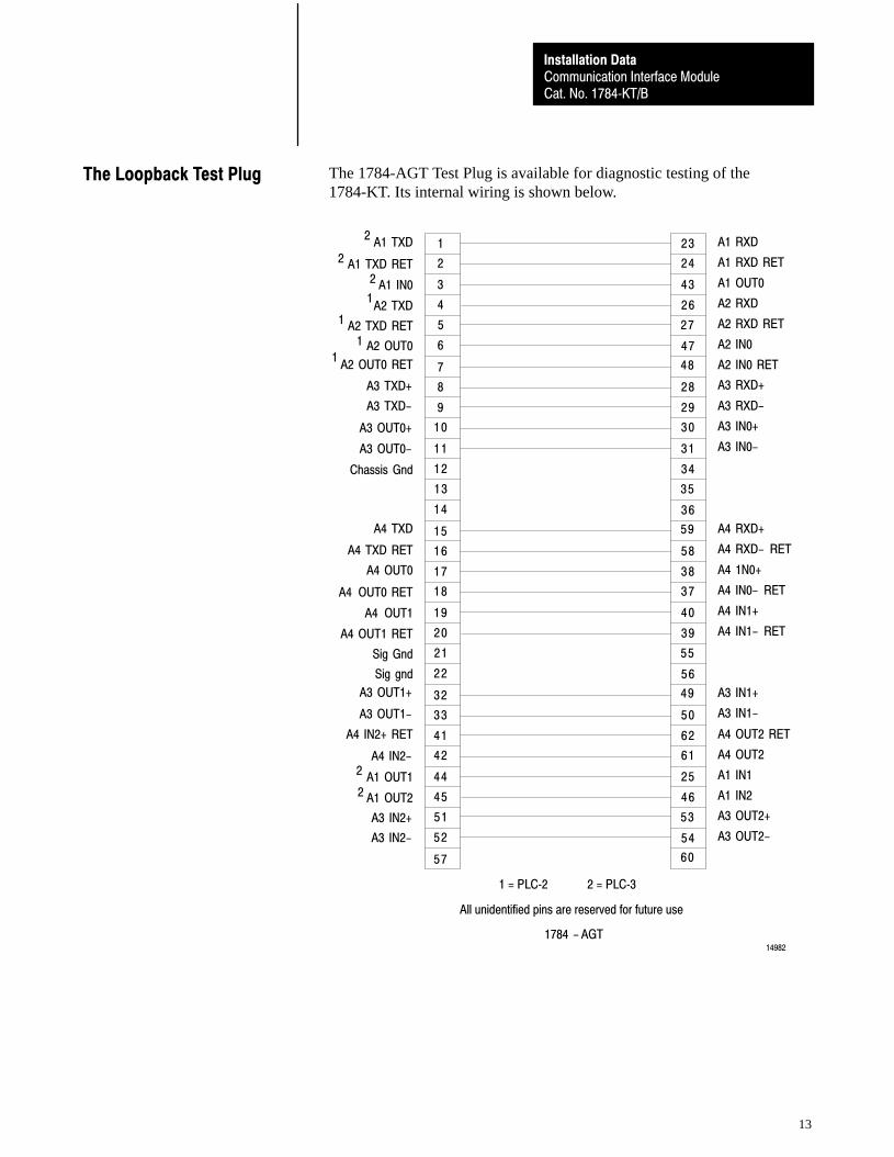
The 1784-AGT Test Plug is available for diagnostic testing of the1784-KT. Its internal wiring is shown below.
1
2
4
8
3
6
5
23
24
43
26
47
28
A1 TXD
A1 TXD RET
A1 IN0
A2 TXD
A2 OUT0
A3 TXD+
A2 TXD RET
7 48
27
A2 OUT0 RET
A1 RXD
A1 RXD RET
A1 OUT0
A2 RXD
A2 RXD RET
A2 IN0
A2 IN0 RET
A3 RXD+
9
10
12
16
11
14
13
15
29
30
31
34
36
58
59
35
17
18
20
33
19
22
21
32
38
37
40
39
56
50
49
55
41
42
45
44
52
51
57
62
61
25
46
54
60
53
A3 RXD-
A3 IN0+
A3 IN0-
A4 RXD+
A4 RXD- RET
A3 TXD-
A3 OUT0+
A3 OUT0-
Chassis Gnd
A4 TXD RET
A4 TXD
A4 1N0+
A4 IN0- RET
A4 IN1+
A4 IN1- RET
A3 IN1+
A3 IN1-
A4 OUT0
A4 OUT0 RET
A4 OUT1
A4 OUT1 RET
Sig gnd
A3 OUT1-
Sig Gnd
A3 OUT1+
A4 OUT2 RET
A4 OUT2
A1 IN1
A1 IN2
A3 OUT2+
A3 OUT2-
A4 IN2+ RET
A4 IN2-
A1 OUT1
A1 OUT2
A3 IN2-
A3 IN2+
1
1
1
1
2
2
2
2
2
1784 - AGT14982
All unidentified pins are reserved for future use
1 = PLC�2 2 = PLC�3
The Loopback Test Plug
Communication Interface ModuleCat. No. 1784�KT/B
Installation Data
14
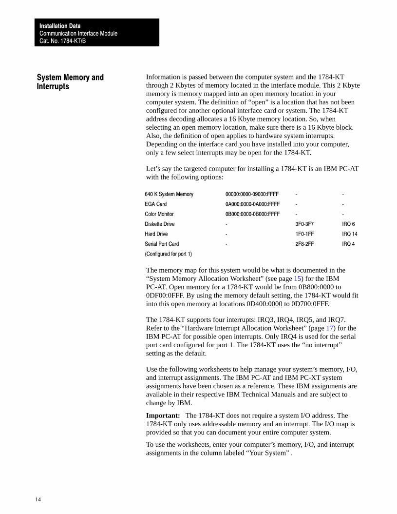
Information is passed between the computer system and the 1784-KTthrough 2 Kbytes of memory located in the interface module. This 2 Kbytememory is memory mapped into an open memory location in yourcomputer system. The definition of “open” is a location that has not beenconfigured for another optional interface card or system. The 1784-KTaddress decoding allocates a 16 Kbyte memory location. So, whenselecting an open memory location, make sure there is a 16 Kbyte block.Also, the definition of open applies to hardware system interrupts.Depending on the interface card you have installed into your computer,only a few select interrupts may be open for the 1784-KT.
Let’s say the targeted computer for installing a 1784-KT is an IBM PC-ATwith the following options:
640 K System Memory 00000:0000�09000:FFFF � �
EGA Card 0A000:0000�0A000:FFFF � �
Color Monitor 0B000:0000�0B000:FFFF � �
Diskette Drive � 3F0�3F7 IRQ 6
Hard Drive � 1F0�1FF IRQ 14
Serial Port Card � 2F8�2FF IRQ 4
(Configured for port 1)
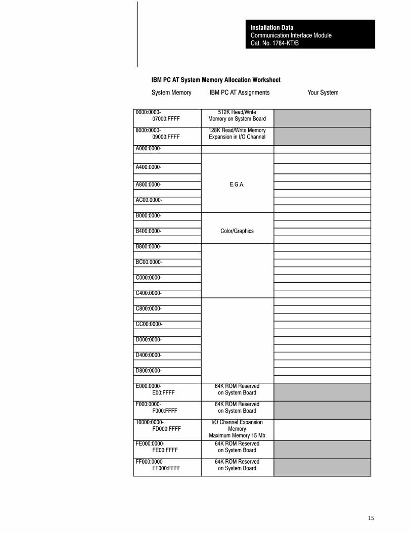
The memory map for this system would be what is documented in the“System Memory Allocation Worksheet” (see page 15) for the IBMPC-AT. Open memory for a 1784-KT would be from 0B800:0000 to0DF00:0FFF. By using the memory default setting, the 1784-KT would fitinto this open memory at locations 0D400:0000 to 0D700:0FFF.
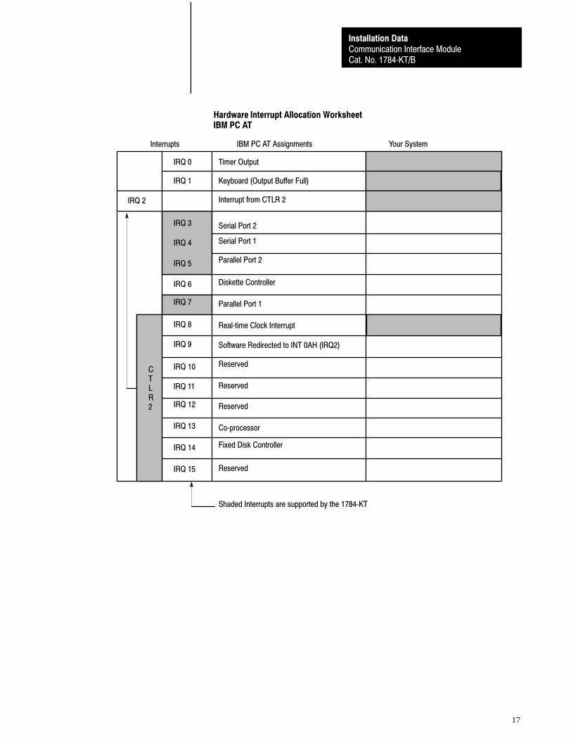
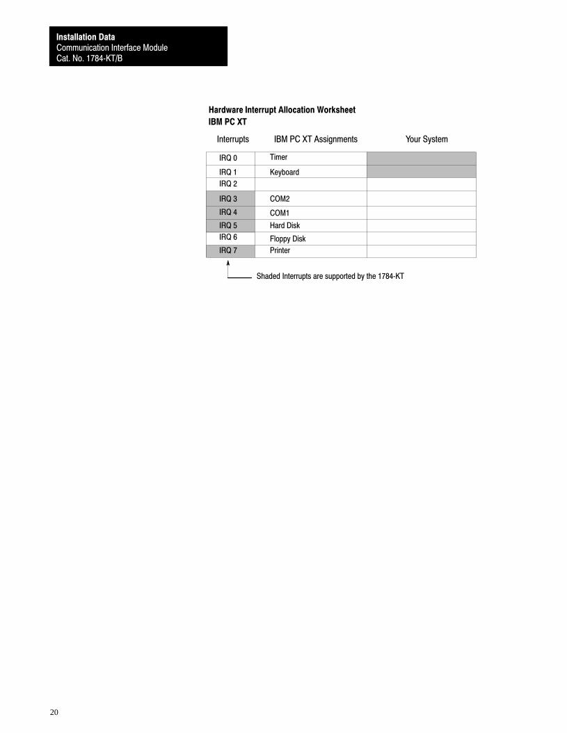
The 1784-KT supports four interrupts: IRQ3, IRQ4, IRQ5, and IRQ7.Refer to the “Hardware Interrupt Allocation Worksheet” (page 17) for theIBM PC-AT for possible open interrupts. Only IRQ4 is used for the serialport card configured for port 1. The 1784-KT uses the “no interrupt”setting as the default.
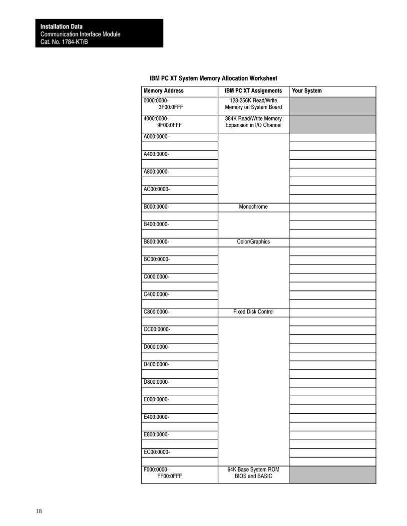
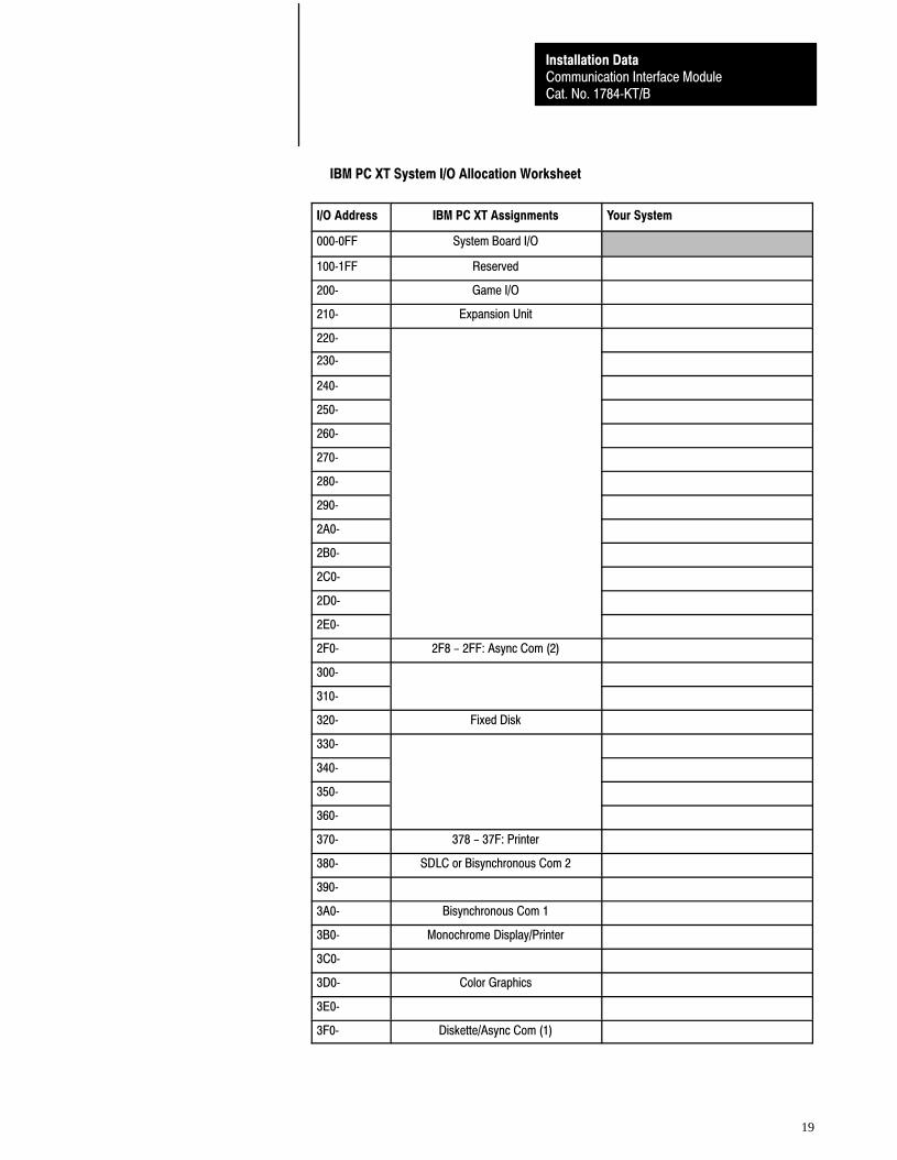
Use the following worksheets to help manage your system’s memory, I/O,and interrupt assignments. The IBM PC-AT and IBM PC-XT systemassignments have been chosen as a reference. These IBM assignments areavailable in their respective IBM Technical Manuals and are subject tochange by IBM.
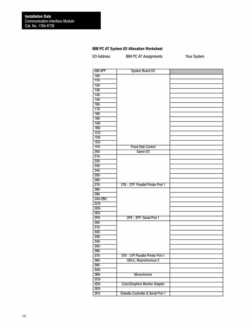
Important: The 1784-KT does not require a system I/O address. The1784-KT only uses addressable memory and an interrupt. The I/O map isprovided so that you can document your entire computer system.
To use the worksheets, enter your computer’s memory, I/O, and interruptassignments in the column labeled “Your System” .
System Memory andInterrupts
Communication Interface ModuleCat. No. 1784�KT/B
Installation Data
15
IBM PC AT System Memory Allocation Worksheet
System Memory IBM PC AT Assignments Your System
0000:0000� 07000:FFFF
512K Read/WriteMemory on System Board
8000:0000� 09000:FFFF
128K Read/Write MemoryExpansion in I/O Channel
��
A000:0000�
A400:0000�
A800:0000� E.G.A.
AC00:0000�
B000:0000�
B400:0000� Color/Graphics
B800:0000�
BC00:0000�
C000:0000�
C400:0000�
C800:0000�
CC00:0000�
D000:0000�
D400:0000�
D800:0000�
E000:0000� E00:FFFF
64K ROM Reservedon System Board
F000:0000� F000:FFFF
64K ROM Reservedon System Board
10000:0000� FD000:FFFF
I/O Channel ExpansionMemory
Maximum Memory 15 Mb
FE000:0000� FE00:FFFF
64K ROM Reservedon System Board
FF000:0000� FF000:FFFF
64K ROM Reservedon System Board
Communication Interface ModuleCat. No. 1784�KT/B
Installation Data
16
IBM PC AT System I/O Allocation Worksheet
I/O Address IBM PC AT Assignments Your System
000�0FF System Board I/O
100�110�
120�
130�
140�
150�
160�
170�
180�
190�
1A0�
1B0�
1C0�
1D0�
1E0�
1F0� Fixed Disk Control
200� Game I/O
210�
220�
230�
240�
250�
260�
270� 278 - 27F: Parallel Printer Port 1
280�
290�
2A0�2B0�
2C0�
2D0�
2E0�
2F0� 2F8 - 2FF: Serial Port 1
300�
310�
320�
330�
340�
350�
360�
370� 378 - 37F:Parallel Printer Port 1
380� SDLC, Bisynchronous 2
390�
3A0�
3B0� Monochrome
3C0�
3D0� Color/Graphics Monitor Adapter
3E0�
3F0� Diskette Controller & Serial Port 1
Communication Interface ModuleCat. No. 1784�KT/B
Installation Data
17
Timer Output
Keyboard (Output Buffer Full)
Interrupt from CTLR 2
Serial Port 2
Serial Port 1
Parallel Port 2
Diskette Controller
Parallel Port 1
Real�time Clock Interrupt
Reserved
Reserved
Reserved
Reserved
Co�processor
Fixed Disk Controller
IRQ 0
IRQ 1
IRQ 2
IRQ 3
IRQ 4
IRQ 5
IRQ 6
IRQ 7
IRQ 8
IRQ 9
IRQ 10
IRQ 11
IRQ 12
IRQ 13
IRQ 14
IRQ 15
CTLR2
Shaded Interrupts are supported by the 1784�KT
Interrupts IBM PC AT Assignments Your System
Hardware Interrupt Allocation WorksheetIBM PC AT
Software Redirected to INT 0AH (IRQ2)
Communication Interface ModuleCat. No. 1784�KT/B
Installation Data
18
IBM PC XT System Memory Allocation Worksheet
Memory Address IBM PC XT Assignments Your System
0000:0000� 3F00:0FFF
128�256K Read/WriteMemory on System Board
4000:0000� 9F00:0FFF
384K Read/Write MemoryExpansion in I/O Channel
A000:0000�
A400:0000�
A800:0000�
AC00:0000�
B000:0000� Monochrome
B400:0000�
B800:0000� Color/Graphics
BC00:0000�
C000:0000�
C400:0000�
C800:0000� Fixed Disk Control
CC00:0000�
D000:0000�
D400:0000�
D800:0000�
E000:0000�
E400:0000�
E800:0000�
EC00:0000�
F000:0000� FF00:0FFF
64K Base System ROMBIOS and BASIC
Communication Interface ModuleCat. No. 1784�KT/B
Installation Data
19
IBM PC XT System I/O Allocation Worksheet
I/O Address IBM PC XT Assignments Your System
000�0FF System Board I/O
100�1FF Reserved
200� Game I/O
210� Expansion Unit
220�
230�
240�
250�
260�
270�
280�
290�
2A0�
2B0�
2C0�
2D0�
2E0�
2F0� 2F8 - 2FF: Async Com (2)
300�
310�
320� Fixed Disk
330�
340�
350�
360�
370� 378 - 37F: Printer
380� SDLC or Bisynchronous Com 2
390�
3A0� Bisynchronous Com 1
3B0� Monochrome Display/Printer
3C0�
3D0� Color Graphics
3E0�
3F0� Diskette/Async Com (1)
Communication Interface ModuleCat. No. 1784�KT/B
Installation Data
20
Hardware Interrupt Allocation Worksheet
IBM PC XT
Interrupts IBM PC XT Assignments Your System
Shaded Interrupts are supported by the 1784�KT
IRQ 7
IRQ 0
IRQ 1
IRQ 2
IRQ 3
IRQ 4
IRQ 5
IRQ 6
Timer
Keyboard
COM2
COM1
Hard Disk
Floppy Disk
Printer
Communication Interface ModuleCat. No. 1784�KT/B
Installation Data
21
Specifications
Module Location
• The 1784�KT/B can be installed in any slot thatsupports ISA 8�bit cards
Module Output Connector
• 62 Pin D�shell
Outputs
• PLC�2 Serial Interface
• PLC�3 Serial Interface
• Data Highway Plus
Module Compatibility
• Allen�Bradley 1771 Information Processor(1771�DSX2) (requires KT Expander Module1771�DXKT)
• Allen�Bradley 1784�T35 Industrial Terminal
• Allen�Bradley 1784�T50 Industrial Terminal
• Allen�Bradley 6121
• Allen�Bradley 6122
• Allen�Bradley T53 Industrial ProgrammingTerminal 6160�T53
• Allen�Bradley T60 Industrial Workstation6160�PCD2, �PCN2, �PCD4, �PCN4
• Allen�Bradley T70 Industrial Workstation6170 series
• IBM�XT/AT, or Compatible
• Compaq Portable 286
• Compaq Portable II
• Compaq Portable III
• Compaq Deskpro 286
• Compaq Deskpro 386
• Dell 316 386SX
• Samsung S550
• Samsung 386
• Hewlett�Packard HP 9000/700 series
Hardware Interrupts
• IRQ3 (Com2)
• IRQ4
• IRQ5
• IRQ7
Baud Rate
• Asynchronous (PLC�2 and PLC�3 Controllers): 9600 19.2 K
• Synchronous (Data Highway Plus): 57.6 K
• PLC�2: 10 ft (3m)
• PLC�3: 10 ft (3m)
• Data Highway Plus
• PLC�3 and PLC�5: 10,000 ft (3,050m) @ 57.6 Kb
Power Requirements
• +5V DC @ .4A (2W)
• �12V DC @ .04 (.48W) respectively
Operating Temperature
• 32 to 1300F (0 to 550C)
Humidity
• 5 to 95% Noncondensing
Specifications for the 1784-KT are listed below.

Communication Interface ModuleCat. No. 1784�KT/B
Installation Data
22
The following are registered trademarks of Allen�Bradley Company, Inc.: PLC, PLC�2, PLC�2/15, PLC�3.The following are trademarks of Allen�Bradley Company, Inc.: Data Highway Plus, PLC�5, ControlView, InterchangeCompaq is a registered trademark of Compaq Computer Corporation.Dell is a registered trademark Dell Computer Corporation.Hewlett�Packard is a registered trademark of Hewlett�Packard Company.HP 9000 is a trademark of Hewlett�Packard Company.IBM, IBM PC AT, IBM PC XT, and IBM PC XT/AT are registered trademarks of International Business Machine Corporation.Advisor PC is a trademark of Dynapro Systems, Inc.
With major offices worldwide.
Algeria • Argentina • Australia • Austria • Bahrain • Belgium • Brazil • Bulgaria • Canada • Chile • China, PRC • Colombia • Costa Rica • Croatia • Cyprus • Czech
Republic • Denmark • Ecuador • Egypt • El Salvador • Finland • France • Germany • Greece • Guatemala • Honduras • Hong Kong • Hungary • Iceland • India •Indonesia • Israel • Italy • Jamaica • Japan • Jordan • Korea • Kuwait • Lebanon • Malaysia • Mexico • New Zealand • Norway • Oman • Pakistan • Peru • Philippines
• Poland • Portugal • Puerto Rico • Qatar • Romania • Russia�CIS • Saudi Arabia • Singapore • Slovakia • Slovenia • South Africa, Republic • Spain • Switzerland •Taiwan • Thailand • The Netherlands • Turkey • United Arab Emirates • United Kingdom • United States • Uruguay • Venezuela • Yugoslavia
World Headquarters, Allen�Bradley, 1201 South Second Street, Milwaukee, WI 53204 USA, Tel: (1) 414 382�2000 Fax: (1) 414 382�4444
Allen�Bradley has been helping its customers improve productivity and quality for 90 years.A�B designs, manufactures and supports a broad range of control and automation productsworldwide. They include logic processors, power and motion control devices, man�machineinterfaces and sensors. Allen�Bradley is a subsidiary of Rockwell International, one of theworld's leading technology companies.
Publication 1784�2.31 August 1993Supersedes Publications 1784�2.31 February 1992 (for 1784�KT/B) and 1784�2.17 May 1991 (for 1784�KT/A)
PN 404637402Copyright 1993 Allen�Bradley Company, Inc. Printed in USA


![INDEX []i...CA(SA), BComm, BComm (Hons), MCom Financial Management Sciences (University of Pretoria), MBA (INSEAD) Independent non-executive director (Appointed: 22 June 2020) Member](https://img.pdfslide.net/doc/110x75/60127f45ff7e0a719c253a49/index-i-casa-bcomm-bcomm-hons-mcom-financial-management-sciences-university.jpg)