Embed Size (px)
Citation preview

International HQ Jerusalem, Israel Tel: + 972 2 535 9666 [email protected]
North American HQ Linden, New Jersey Tel: + 1 908 4862100 [email protected]
German Europe Zurich, Switzerland Tel: + 41 1 455 6220 [email protected]
Italy Rome Tel: + 39 06 8209 7902 [email protected]
www.minicom.com Customer support - [email protected]
5UM30096 V2.1 11/02
CAT5 Smart KVM Extender
User Guide
1
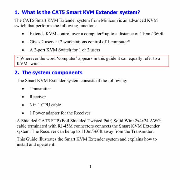
1. What is the CAT5 Smart KVM Extender system? The CAT5 Smart KVM Extender system from Minicom is an advanced KVM switch that performs the following functions:
• Extends KVM control over a computer* up to a distance of 110m / 360ft
• Gives 2 users at 2 workstations control of 1 computer*
• A 2-port KVM Switch for 1 or 2 users
* Wherever the word ‘computer’ appears in this guide it can equally refer to a KVM switch.
2. The system components The Smart KVM Extender system consists of the following:
• Transmitter
• Receiver
• 3 in 1 CPU cable
• 1 Power adapter for the Receiver
A Shielded CAT5 FTP (Foil Shielded Twisted Pair) Solid Wire 2x4x24 AWG cable terminated with RJ-45M connectors connects the Smart KVM Extender system. The Receiver can be up to 110m/360ft away from the Transmitter.
This Guide illustrates the Smart KVM Extender system and explains how to install and operate it.
2
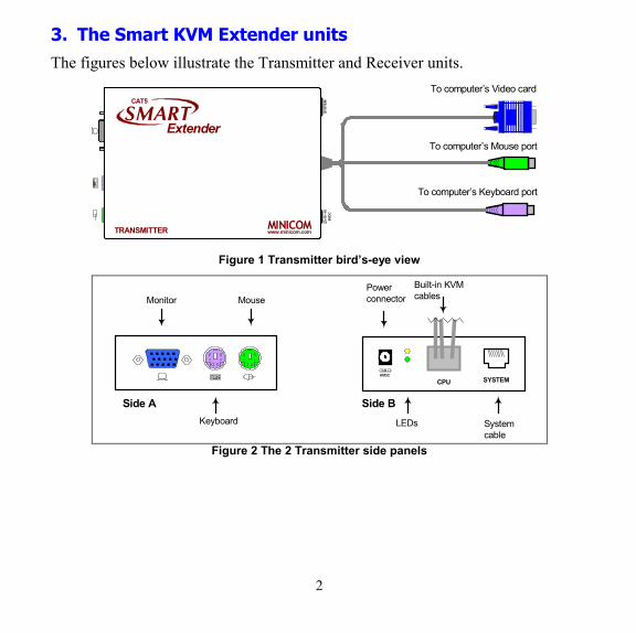
3. The Smart KVM Extender units The figures below illustrate the Transmitter and Receiver units.
CAT5
SMARTExtender
TRANSMITTER MINICOMwww.minicom.com
SYST
EM6V
DC
To computer’s Mouse port
To computer’s Video card
To computer’s Keyboard port
Figure 1 Transmitter bird’s-eye view
SYSTEMCPU
Built-in KVMcables
Systemcable
Powerconnector
6VDC
LEDs
MouseMonitor
Keyboard
Side A Side B
Figure 2 The 2 Transmitter side panels
3
6VDCSYSTEM
CAT5
SMARTExtender
RECEIVER MINICOMwww.minicom.com
PICTURE
SELECT
USER COMPUTER
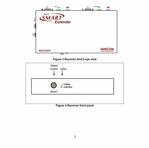
Figure 3 Receiver bird’s-eye view
SELECT
POWERCONTROL
Selectbutton LEDs
Figure 4 Receiver front panel
4
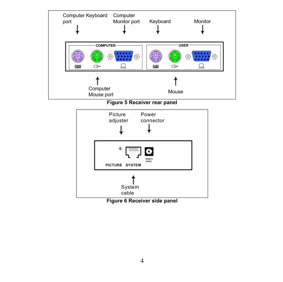
COMPUTER USER
Keyboard
Mouse
Monitor
ComputerMouse port
Computer Keyboardport
ComputerMonitor port
Figure 5 Receiver rear panel
6VDC
SYSTEMPICTURE
Pictureadjuster
Systemcable
Powerconnector
Figure 6 Receiver side panel
5
4. Pre-installation instructions Disconnect all computers from the electrical power supply.
Place cables away from fluorescent lights, air conditioners, and machines that are likely to generate electrical noise.
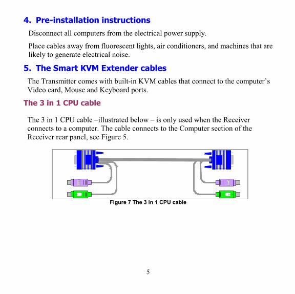
5. The Smart KVM Extender cables The Transmitter comes with built-in KVM cables that connect to the computer’s Video card, Mouse and Keyboard ports.
The 3 in 1 CPU cable
The 3 in 1 CPU cable –illustrated below – is only used when the Receiver connects to a computer. The cable connects to the Computer section of the Receiver rear panel, see Figure 5.
Figure 7 The 3 in 1 CPU cable
6
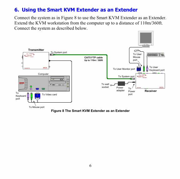
6. Using the Smart KVM Extender as an Extender Connect the system as in Figure 8 to use the Smart KVM Extender as an Extender. Extend the KVM workstation from the computer up to a distance of 110m/360ft. Connect the system as described below.
CAT5
S M A R TExtender
RECEIVER MINICOMwww.minicom.com
CAT5
S M A R TExtender
TRANSMITTERMINICOM
www.minicom.com
6VD
C
To Video card
SD
DESKPRO Ω To wallsocket
SDP110
Computer
ToKeyboardport
To Mouse port
Transmitter
Receiver
To System port
CAT5 FTP cableUp to 110m / 360ft
Poweradapter
ToPowerport
To User Monitor portTo UserKeyboard port
To UserMouseport
To System port
Figure 8 The Smart KVM Extender as an Extender

7
Connecting the Transmitter
Connect the Transmitter built-in cables to the computer as follows:
Connect the purple Mouse connector to the computer’s mouse port.
Connect the green Keyboard connector to the computer’s Keyboard port.
Connect the blue Video connector to the computer’s Video card.
Connecting the CAT FTP System cable
Connect the CAT FTP System cable to the System ports of the 2 Smart Extender units.
Connecting the Receiver
Connect a monitor, keyboard and mouse to the User ports on the Receiver’s rear panel.
7. Power supply Connect the Receiver to the power supply with the Power adapter and Power cord provided. The Transmitter receives it power from the connected computer and does not generally need an external power supply. When cascading Smart Extenders the Transmitter does need an external power supply. See page 19.
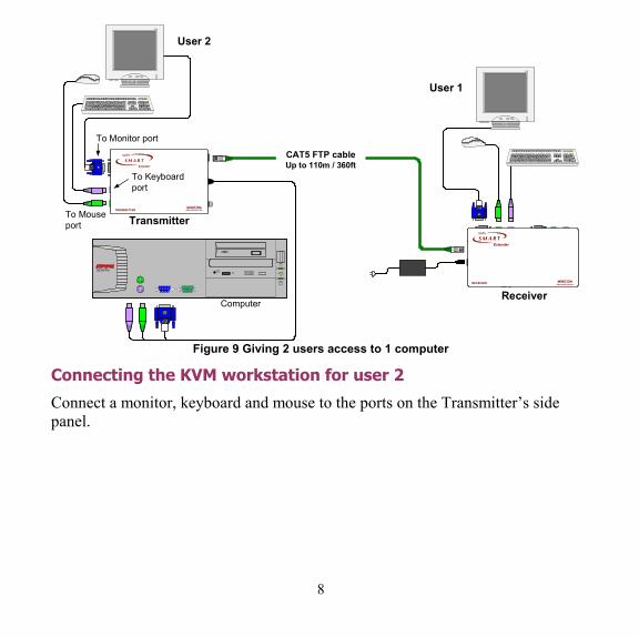
8. Using the Smart KVM Extender to give 2 users access to 1 computer
Connect the system as in Figure 9 to give 2 users access to 1 computer on a first-come-first-served basis. The connections are the same as in Figure 8, with the addition of a KVM workstation for user 2. Connect the workstation for user 2 as described below.
8
CAT5
S M A R TExtender
RECEIVER MINICOMwww.minicom.com
CAT5
S M A R TExtender
TRANSMITTERMINICOM
www.minicom.com6V
DC
SD
DESKPRO Ω
SDP110
Computer
Transmitter
Receiver
CAT5 FTP cableUp to 110m / 360ft
To Monitor port
SDP110
To Keyboardport
To Mouseport
User 1
User 2
Figure 9 Giving 2 users access to 1 computer
Connecting the KVM workstation for user 2
Connect a monitor, keyboard and mouse to the ports on the Transmitter’s side panel.
9
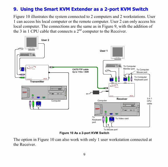
9. Using the Smart KVM Extender as a 2-port KVM Switch Figure 10 illustrates the system connected to 2 computers and 2 workstations. User 1 can access his local computer or the remote computer. User 2 can only access his local computer. The connections are the same as in Figure 9, with the addition of the 3 in 1 CPU cable that connects a 2nd computer to the Receiver.
CAT5
SM A R TExtender
RECEIVER MINICOMwww.minicom.com
CAT5
S M A R TExtender
TRANSMITTERMINICOM
www.minicom.com
6VD
C
SD
DESKPRO Ω
SDP1 10
Computer
Transmitter
Receiver
CAT5 FTP cableUp to 110m / 360ft
SDP110
User 1
User 2
3 in 1CPUcableSD
DESKPRO Ω
To Video cardToKeyboardport
To Mouse port
To ComputerMonitor port
To ComputerKeyboard port
To ComputerMouse port
Computer
Figure 10 As a 2-port KVM Switch
The option in Figure 10 can also work with only 1 user workstation connected at the Receiver.
10
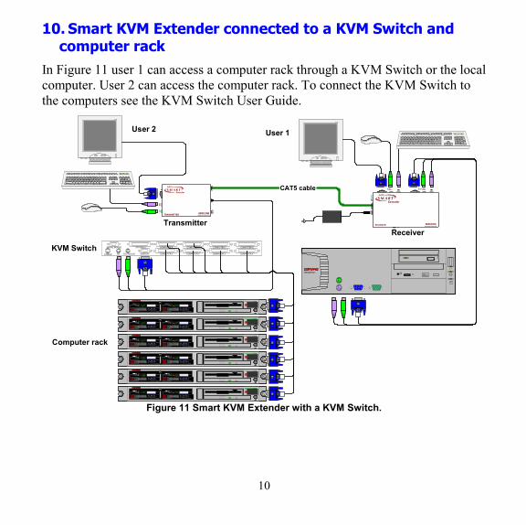
10. Smart KVM Extender connected to a KVM Switch and computer rack
In Figure 11 user 1 can access a computer rack through a KVM Switch or the local computer. User 2 can access the computer rack. To connect the KVM Switch to the computers see the KVM Switch User Guide.
CAT5 cable
6VDCSYS
TEM
CAT5
S M A R TExtender
RECEIVER MINICOMwww.minicom.com
PIC
TURE
SELECT
USER COMPUTER
CAT5S M A R T
Extender
TRANSMITTER MINICOMwww.minicom.com
SYS
TEM
6VD
C
SD
DESKPRO Ω
COMPUTER 1 COMPUTER 2
COMPUTER 6COMPUTER 5STATION 2
SCREENPS/2 MOUSEKBPOWER
SERIAL MOUSE
COMPUTER 3 COMPUTER 4
COMPUTER 8COMPUTER 7KVM Switch
SDP110
ProLiant DL360
9.1 - GB 10kULTRA2 SCSI
9.1 - GB 10kULTRA2 SCSI
ProLiant DL360
9.1 - GB 10kULTRA2 SCSI
9.1 - GB 10kULTRA2 SCSI
ProLiant DL360
9.1 - GB 10kULTRA2 SCSI
9.1 - GB 10kULTRA2 SCSI
ProLiant DL360
9.1 - GB 10kULTRA2 SCSI
9.1 - GB 10kULTRA2 SCSI
ProLiant DL360
9.1 - GB 10kULTRA2 SCSI
9.1 - GB 10kULTRA2 SCSI
ProLiant DL360
9.1 - GB 10kULTRA2 SCSI
9.1 - GB 10kULTRA2 SCSI
TransmitterReceiver
SDP110
Computer rack
User 1User 2
Figure 11 Smart KVM Extender with a KVM Switch.
11
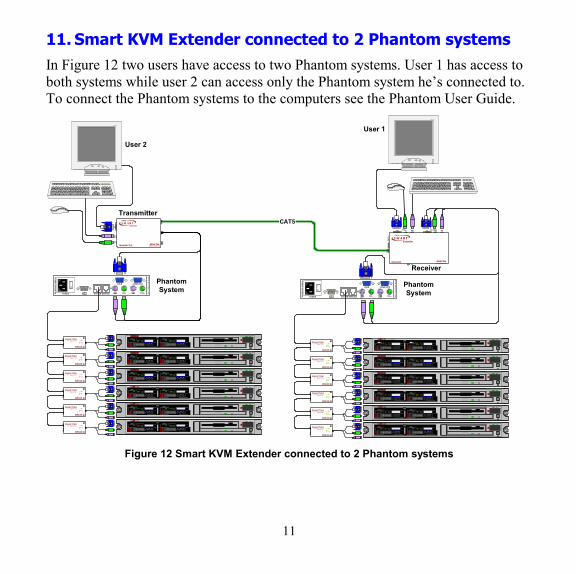
11. Smart KVM Extender connected to 2 Phantom systems In Figure 12 two users have access to two Phantom systems. User 1 has access to both systems while user 2 can access only the Phantom system he’s connected to. To connect the Phantom systems to the computers see the Phantom User Guide.
CAT5
6VDCSYSTEM
CAT5
S M A R TExtender
RECEIVER MINICOMwww.minicom.com
PICTURE
SELECT
USER COMPUTER
CAT5S M A R T
Extender
TRANSMITTER MINICOMwww.minicom.com
SYST
EM6V
DC
ProLiant DL360
9.1 - GB 10kULTRA2 SCSI
9.1 - GB 10kULTRA2 SCSI
ProLiant DL360
9.1 - GB 10kULTRA2 SCSI
9.1 - GB 10kULTRA2 SCSI
ProLiant DL360
9.1 - GB 10kULTRA2 SCSI
9.1 - GB 10kULTRA2 SCSI
ProLiant DL360
9.1 - GB 10kULTRA2 SCSI
9.1 - GB 10kULTRA2 SCSI
ProLiant DL360
9.1 - GB 10kULTRA2 SCSI
9.1 - GB 10kULTRA2 SCSI
ProLiant DL360
9.1 - GB 10kULTRA2 SCSI
9.1 - GB 10kULTRA2 SCSI
ww
w.m
inic
om
.co
m
USER COMPUTER
SYSTEM SERVICEPOWER85-2
65V
AC
50/
60 H
z
L ink
Active
MINICOMwww.m inicom.com
PHANTOMS p e c t e r
OU
TIN
L ink
Active
MINICOMwww.m inicom.com
PHANTOMS p e c t e r
OU
TIN
L ink
Active
MINICOMwww.m inicom.com
PHANTOMS p e c t e r
OU
TIN
L ink
Active
MINICOMwww.m inicom.com
PHANTOMS p e c t e r
OU
TIN
L ink
Active
MINICOMwww.m inicom.com
PHANTOMS p e c t e r
OU
TIN
L ink
Active
MINICOMwww.m inicom.com
PHANTOMS p e c t e r
OU
TIN
PhantomSystem
ProLiant DL360
9.1 - GB 10kULTRA2 SCSI
9.1 - GB 10kULTRA2 SCSI
ProLiant DL360
9.1 - GB 10kULTRA2 SCSI
9.1 - GB 10kULTRA2 SCSI
ProLiant DL360
9.1 - GB 10kULTRA2 SCSI
9.1 - GB 10kULTRA2 SCSI
ProLiant DL360
9.1 - GB 10kULTRA2 SCSI
9.1 - GB 10kULTRA2 SCSI
ProLiant DL360
9.1 - GB 10kULTRA2 SCSI
9.1 - GB 10kULTRA2 SCSI
ProLiant DL360
9.1 - GB 10kULTRA2 SCSI
9.1 - GB 10kULTRA2 SCSI
ww
w.m
inic
om
.co
m
USER COMPUTER
SYSTEM SERVICEPOWER85-2
65VA
C 5
0/60
Hz
L ink
Active
MINICOMwww.m inicom.com
PHANTOMS p e c t e r
OU
TIN
L ink
Active
MINICOMwww.m inicom.com
PHANTOMS p e c t e r
OU
TIN
L ink
Active
MINICOMwww.m inicom.com
PHANTOMS p e c t e r
OU
TIN
L ink
Active
MINICOMwww.m inicom.com
PHANTOMS p e c t e r
OU
TIN
L ink
Active
MINICOMwww.m inicom.com
PHANTOMS p e c t e r
OU
TIN
L ink
Active
MINICOMwww.m inicom.com
PHANTOMS p e c t e r
OU
TIN
PhantomSystem
S DP 1 1 0
Transmitter
Receiver
User 1
User 2
S DP 1 1 0
Figure 12 Smart KVM Extender connected to 2 Phantom systems
12
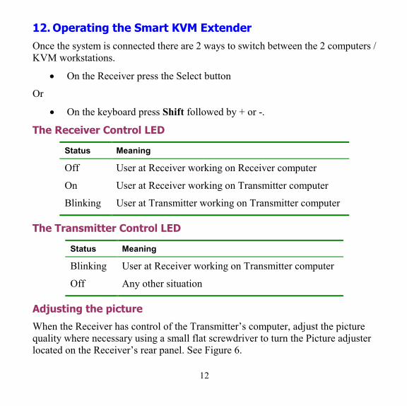
12. Operating the Smart KVM Extender Once the system is connected there are 2 ways to switch between the 2 computers / KVM workstations.
• On the Receiver press the Select button
Or
• On the keyboard press Shift followed by + or -.
The Receiver Control LED
Status Meaning
Off User at Receiver working on Receiver computer
On User at Receiver working on Transmitter computer
Blinking User at Transmitter working on Transmitter computer
The Transmitter Control LED
Status Meaning
Blinking User at Receiver working on Transmitter computer
Off Any other situation
Adjusting the picture
When the Receiver has control of the Transmitter’s computer, adjust the picture quality where necessary using a small flat screwdriver to turn the Picture adjuster located on the Receiver’s rear panel. See Figure 6.
13
Timeout
When there are 2 workstations in the system you can gain control at each workstation when the other workstation is idle for 2 seconds. This timeout period can be altered in the settings mode to between 1-99 seconds, as explained below.
Locking KVM control
When there are 2 users using the system, either user can override the Timeout feature and retain control indefinitely. Do so by locking the system so that only one user has control.
To lock control:
On the keyboard press Shift followed by F12.
To relinquish control:
On the keyboard press Shift followed by Esc.
In the settings mode you can disable the lock control function. This is explained in the Settings mode paragraph below.
13. Smart KVM Extender Settings mode Enter the Settings mode to:
• Change the hotkey
• Change the Timeout period
• Enable/disable lock control
• Make advanced adjustments
• View settings
14
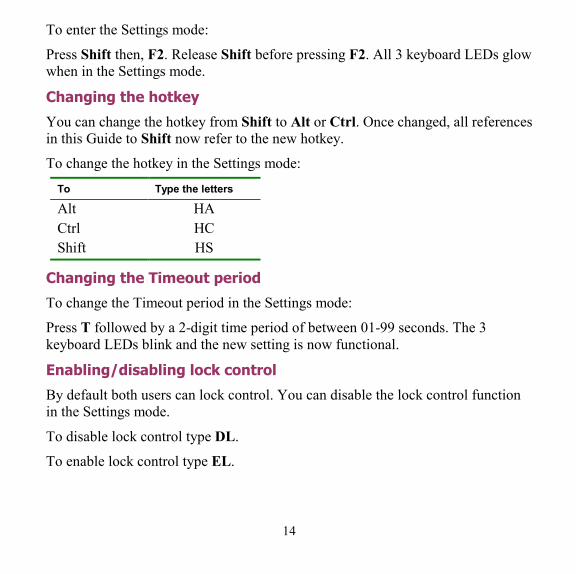
To enter the Settings mode:
Press Shift then, F2. Release Shift before pressing F2. All 3 keyboard LEDs glow when in the Settings mode.
Changing the hotkey
You can change the hotkey from Shift to Alt or Ctrl. Once changed, all references in this Guide to Shift now refer to the new hotkey.
To change the hotkey in the Settings mode:
To Type the letters
Alt HA Ctrl HC Shift HS
Changing the Timeout period
To change the Timeout period in the Settings mode:
Press T followed by a 2-digit time period of between 01-99 seconds. The 3 keyboard LEDs blink and the new setting is now functional.
Enabling/disabling lock control
By default both users can lock control. You can disable the lock control function in the Settings mode.
To disable lock control type DL.
To enable lock control type EL.
15
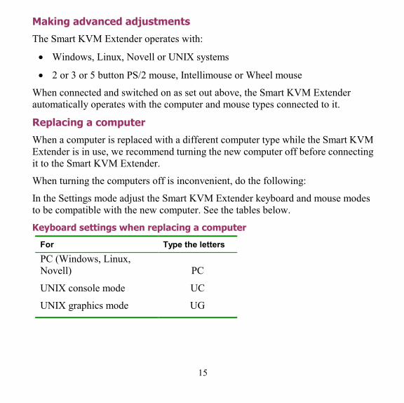
Making advanced adjustments
The Smart KVM Extender operates with:
• Windows, Linux, Novell or UNIX systems
• 2 or 3 or 5 button PS/2 mouse, Intellimouse or Wheel mouse
When connected and switched on as set out above, the Smart KVM Extender automatically operates with the computer and mouse types connected to it.
Replacing a computer
When a computer is replaced with a different computer type while the Smart KVM Extender is in use, we recommend turning the new computer off before connecting it to the Smart KVM Extender.
When turning the computers off is inconvenient, do the following:
In the Settings mode adjust the Smart KVM Extender keyboard and mouse modes to be compatible with the new computer. See the tables below.
Keyboard settings when replacing a computer
For Type the letters PC (Windows, Linux, Novell)
PC
UNIX console mode UC
UNIX graphics mode UG
16
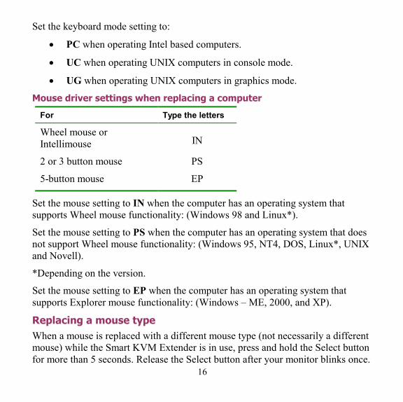
Set the keyboard mode setting to:
• PC when operating Intel based computers.
• UC when operating UNIX computers in console mode.
• UG when operating UNIX computers in graphics mode.
Mouse driver settings when replacing a computer
For Type the letters
Wheel mouse or Intellimouse IN
2 or 3 button mouse PS
5-button mouse EP
Set the mouse setting to IN when the computer has an operating system that supports Wheel mouse functionality: (Windows 98 and Linux*).
Set the mouse setting to PS when the computer has an operating system that does not support Wheel mouse functionality: (Windows 95, NT4, DOS, Linux*, UNIX and Novell).
*Depending on the version.
Set the mouse setting to EP when the computer has an operating system that supports Explorer mouse functionality: (Windows – ME, 2000, and XP).
Replacing a mouse type When a mouse is replaced with a different mouse type (not necessarily a different mouse) while the Smart KVM Extender is in use, press and hold the Select button for more than 5 seconds. Release the Select button after your monitor blinks once.
17
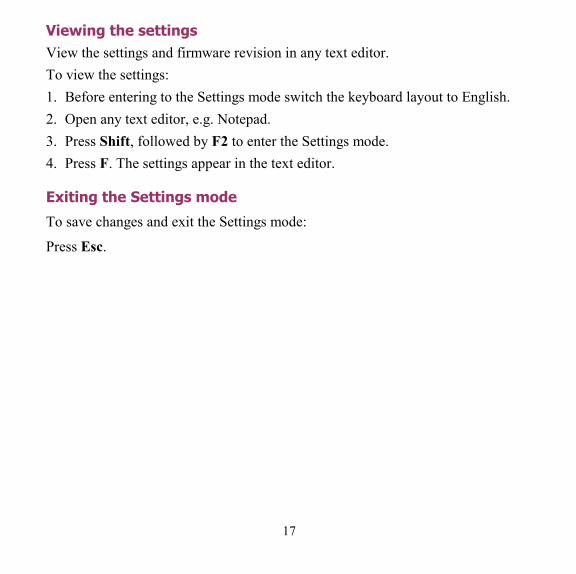
Viewing the settings View the settings and firmware revision in any text editor. To view the settings: 1. Before entering to the Settings mode switch the keyboard layout to English. 2. Open any text editor, e.g. Notepad. 3. Press Shift, followed by F2 to enter the Settings mode. 4. Press F. The settings appear in the text editor.
Exiting the Settings mode
To save changes and exit the Settings mode:
Press Esc.
18
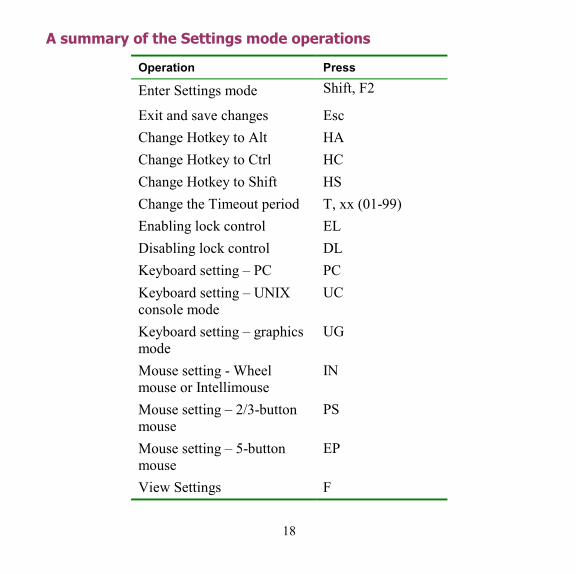
A summary of the Settings mode operations
Operation Press
Enter Settings mode Shift, F2
Exit and save changes Esc Change Hotkey to Alt HA Change Hotkey to Ctrl HC Change Hotkey to Shift HS Change the Timeout period T, xx (01-99) Enabling lock control EL Disabling lock control DL Keyboard setting – PC PC Keyboard setting – UNIX console mode
UC
Keyboard setting – graphics mode
UG
Mouse setting - Wheel mouse or Intellimouse
IN
Mouse setting – 2/3-button mouse
PS
Mouse setting – 5-button mouse
EP
View Settings F
19
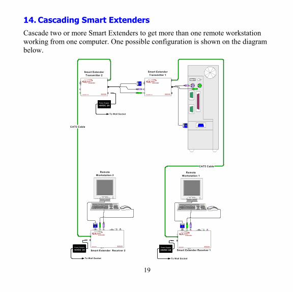
14. Cascading Smart Extenders Cascade two or more Smart Extenders to get more than one remote workstation working from one computer. One possible configuration is shown on the diagram below.
CAT5
S M A R TExtender
TRAN SMITTER MINICOMwww.min icom .com
SYS
TEM
6VDC
S DP 1 1 0
CAT5
S M A R TExtender
TRANSMITTER M INICOMwww. min icom .com
SYS
TEM
6VDC
6VDC
SYSTEM
CAT5
S M A R TExtender
RECEIVER MINICOMwww.mi nico m.co m
PICTURE
SELECT
USER COMPUTER
S D
P 1 1 0
6VDCSYS
TEM
CAT5
S M A R TExtender
REC EIVER MINICOMwww.m inico m.co m
PICTU
RE
SELECT
USER COMPUTER
CAT5 Cable
CAT5 Cable
RemoteWorkstation 2
RemoteWorkstation 1
Smart ExtenderTransmitter 1
Smart ExtenderTransmitter 2
Smart Extender Receiver 2 Smart Extender Receiver 1Power Supply
+6VDC 2A
To Wall Socket
Power Supply
+6VDC 2A
To Wall Socket
Power Supply
+6VDC 2A
To Wall Socket

20
Transmitter Power adapter
To ensure mouse and keyboard functionality connect an external power adapter +6VDC 2A to the second Smart Extender Transmitter unit – see the figure above.
Switching on
Switch the system on in the following order:
1. The second Smart Extender Transmitter unit
2. The rest of the system, including the shared computer.
21
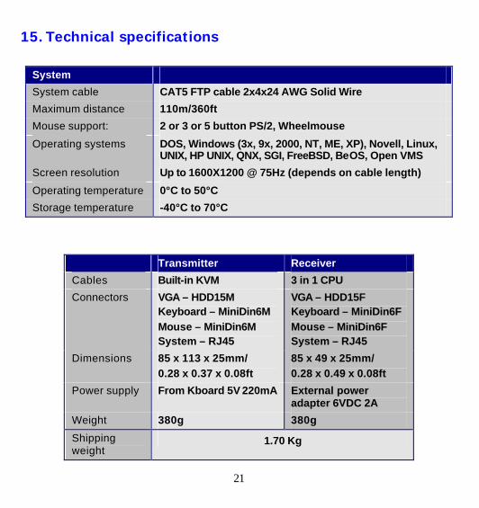
15. Technical specifications
System
System cable CAT5 FTP cable 2x4x24 AWG Solid Wire
Maximum distance 110m/360ft
Mouse support: 2 or 3 or 5 button PS/2, Wheelmouse
Operating systems DOS, Windows (3x, 9x, 2000, NT, ME, XP), Novell, Linux, UNIX, HP UNIX, QNX, SGI, FreeBSD, BeOS, Open VMS
Screen resolution Up to 1600X1200 @ 75Hz (depends on cable length)
Operating temperature 0°C to 50°C
Storage temperature -40°C to 70°C
Transmitter Receiver
Cables Built-in KVM 3 in 1 CPU
Connectors VGA – HDD15M Keyboard – MiniDin6M Mouse – MiniDin6M System – RJ45
VGA – HDD15F Keyboard – MiniDin6F Mouse – MiniDin6F System – RJ45
Dimensions 85 x 113 x 25mm/ 0.28 x 0.37 x 0.08ft
85 x 49 x 25mm/ 0.28 x 0.49 x 0.08ft
Power supply From Kboard 5V 220mA External power adapter 6VDC 2A
Weight 380g 380g
Shipping weight
1.70 Kg