Embed Size (px)
Citation preview
Catalog 580
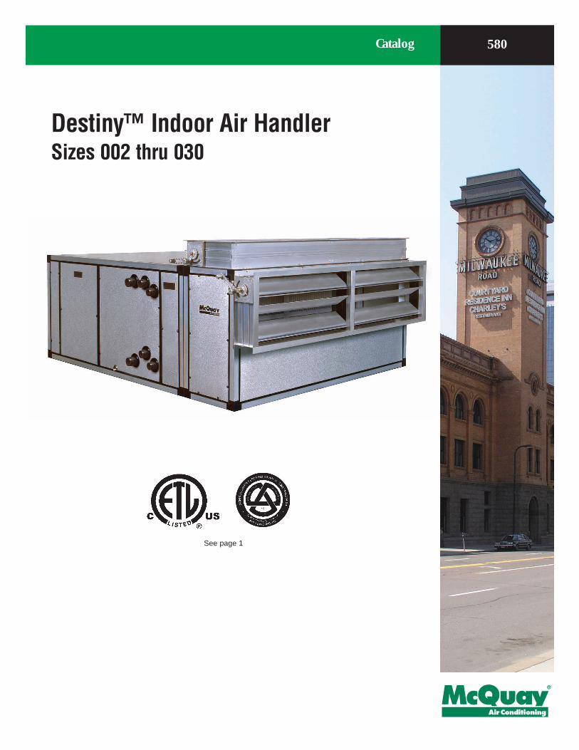
Destiny™ Indoor Air HandlerSizes 002 thru 030
See page 1
NomenclatureARI Certification
Standard size units certified in accor-dance with the central station air han-dling units certification program, which is based on ARI Standard 430.
.
Agency Listed
Smoke-Control and Management Systems
Table of ContentsNomenclature . . . . . . . . . . . . . . . . . . . . . . . . . . . . . .1Agency Listed . . . . . . . . . . . . . . . . . . . . . . . . . . . . . . . . . . . . . . . . . 1Smoke-Control and Management Systems . . . . . . . . . . . . . . . . . . . 1
The Destiny™ Advantage . . . . . . . . . . . . . . . . . . . . .2Features and Benefits . . . . . . . . . . . . . . . . . . . . . . .4Flexibility . . . . . . . . . . . . . . . . . . . . . . . . . . . . . . . . . . . . . . . . . . . . . 4Indoor Air Quality . . . . . . . . . . . . . . . . . . . . . . . . . . . . . . . . . . . . . . . 5
Options . . . . . . . . . . . . . . . . . . . . . . . . . . . . . . . . . . .5Application considerations . . . . . . . . . . . . . . . . . . .6Mounting and access . . . . . . . . . . . . . . . . . . . . . . . . . . . . . . . . . . . . 6Ductwork . . . . . . . . . . . . . . . . . . . . . . . . . . . . . . . . . . . . . . . . . . . . . 6Piping and drain pan traps . . . . . . . . . . . . . . . . . . . . . . . . . . . . . . . . 6Vibration isolation . . . . . . . . . . . . . . . . . . . . . . . . . . . . . . . . . . . . . . 6Sound . . . . . . . . . . . . . . . . . . . . . . . . . . . . . . . . . . . . . . . . . . . . . . . 6
Air supply systems and fan laws. . . . . . . . . . . . . . . . . . . . . . . . . . . 7Fan and motor heat . . . . . . . . . . . . . . . . . . . . . . . . . . . . . . . . . . . . . 7
Engineering and physical data . . . . . . . . . . . . . . . 9Component and Section Weights . . . . . . . . . . . . . . . . . . . . . . . . . . . 9Fan Data . . . . . . . . . . . . . . . . . . . . . . . . . . . . . . . . . . . . . . . . . . . . 10Filter Data . . . . . . . . . . . . . . . . . . . . . . . . . . . . . . . . . . . . . . . . . . . 10Coil Data . . . . . . . . . . . . . . . . . . . . . . . . . . . . . . . . . . . . . . . . . . . . 11
Dimensional data . . . . . . . . . . . . . . . . . . . . . . . . . 12Engineering guide specification . . . . . . . . . . . . . 13PART 1: GENERAL . . . . . . . . . . . . . . . . . . . . . . . . . . . . . . . . . . . . 13PART 2: PRODUCTS . . . . . . . . . . . . . . . . . . . . . . . . . . . . . . . . . . 14PART 3: EXECUTION . . . . . . . . . . . . . . . . . . . . . . . . . . . . . . . . . . 15
"Destiny" and "SelectTOOLS " are trademarks of McQuay International. All rights reserved.© 2003 McQuay International. All rights reserved throughout the world.
Bulletin illustrations cover the general appearance of McQuay International products at the time of publication. We reserve the right to change design and construction specifications at any time without notice.
All standard unitsAll Canadian units
WARNING
Improper smoke or fume air handling can result in severe personal injury or death.A registered Professional Engineer must design and approve the air conditioner and air handler applica-tion to make sure smoke and fume control meet local fire codes and NFPA requirements for the specific building application. Due to the wide variation in building design and ambient operating conditions into which our products can be applied, we do not represent or warrant that our products will be fit and sufficient for smoke and fume control and management purposes. The owner and building designer must consult a registered Pro-fessional Engineer in order to satisfy themselves in this regard.
Document Number: Cat 580
Cat 580 1
The Destiny™ Advantage
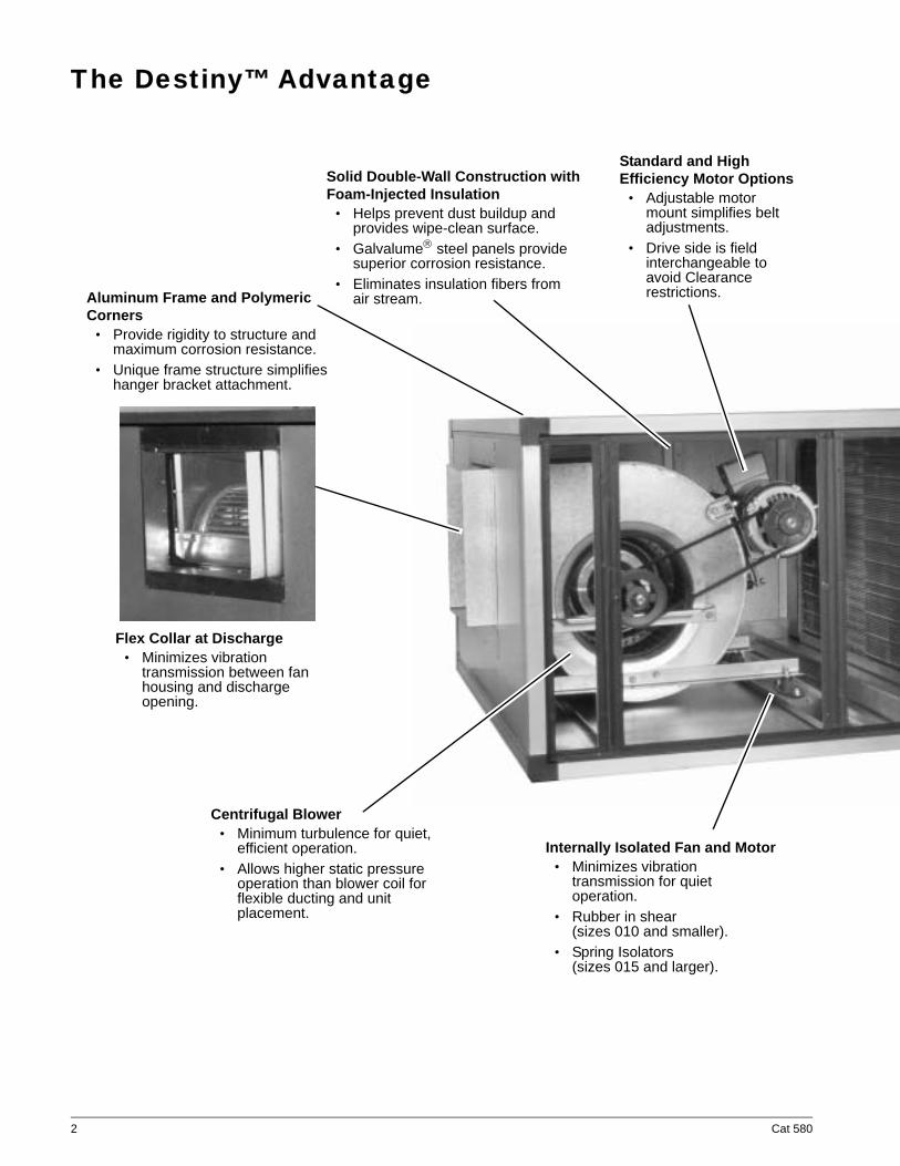
Aluminum Frame and Polymeric Corners
• Provide rigidity to structure and maximum corrosion resistance.
• Unique frame structure simplifies hanger bracket attachment.
Solid Double-Wall Construction with Foam-Injected Insulation
• Helps prevent dust buildup and provides wipe-clean surface.
• Galvalume steel panels provide superior corrosion resistance.
• Eliminates insulation fibers from air stream.
Standard and High Efficiency Motor Options
• Adjustable motor mount simplifies belt adjustments.
• Drive side is field interchangeable to avoid Clearance restrictions.
Internally Isolated Fan and Motor• Minimizes vibration
transmission for quiet operation.
• Rubber in shear (sizes 010 and smaller).
• Spring Isolators (sizes 015 and larger).
Flex Collar at Discharge• Minimizes vibration
transmission between fan housing and discharge opening.
Centrifugal Blower• Minimum turbulence for quiet,
efficient operation.• Allows higher static pressure
operation than blower coil for flexible ducting and unit placement.
2 Cat 580
SD
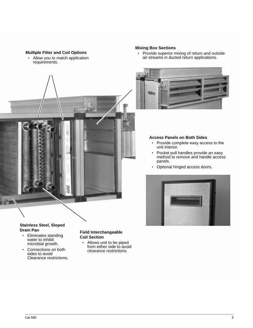
Mixing Box Sections • Provide superior mixing of return and outside
air streams in ducted return applications.
tainless Steel, Sloped rain Pan• Eliminates standing
water to inhibit microbial growth.
• Connections on both sides to avoid Clearance restrictions.
Field Interchangeable Coil Section
• Allows unit to be piped from either side to avoid clearance restrictions.
Multiple Filter and Coil Options• Allow you to match application
requirements.
Access Panels on Both Sides• Provide complete easy access to the
unit interior.• Pocket pull handles provide an easy
method to remove and handle access panels.
• Optional hinged access doors.
Cat 580 3
Features and BenefitsThe McQuay Destiny™ air handler is a full featured, lite air handler that provides a single, economical solution for blower coil and low pressure air handler applica-tions from 600 to 15,000 cfm. Destiny air handlers include many features that make it a superior choice over blower coils and other low pressure air handlers, including:
• Double-wall construction with foam injected insulation for durable construction, easy cleaning and superior IAQ.
• Internally isolated fan and motor assembly with a flex collar on the fan discharge for low vibration and quieter operation.
• ARI Certified fan performance for all sizes.• Capable of higher operating static pressures than
blower coils for greater flexibility in ducting and placement.
• Easy maintenance and service access on both sides.
FlexibilityThe McQuay Destiny™ air handler is available in hori-zontal configurations with chilled water or direct expan-sion (DX) cooling, and hot water, steam or electric heat. Units can be floor mounted or ceiling hung. The coil section is field-interchangeable, allowing the unit to be piped from either side to help avoid obstructions, conserve space and simplify installation. Drain connec-tions on both ends of the stainless steel drain pan fur-ther support this flexibility.
Coil SelectionsCoil selections include:
• Chilled water with 4 or 6 rows and 12 fins per inch
• Direct expansion with 4 or 6 rows and 12 fins per inch
• Hot water with 1 or 2 rows and 12 fins per inch• Steam with 1 or 2 rows and 12 fins per inch
All coils are rated in accordance with ARI Standard 410 and built with copper tubing and corrugated aluminum fins mounted in a galvanized steel casing.
Filter SelectionsFilter selections include:
• 2" or 4" flat filters (30% or 70% efficiency)• 2" angular filters (30% or 70% efficiency)
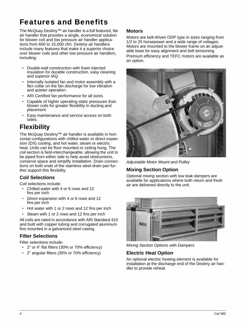
MotorsMotors are belt-driven ODP type in sizes ranging from 1/2 to 25 horsepower and a wide range of voltages. Motors are mounted to the blower frame on an adjust-able base for easy alignment and belt tensioning. Premium efficiency and TEFC motors are available as an option.
Adjustable Motor Mount and Pulley
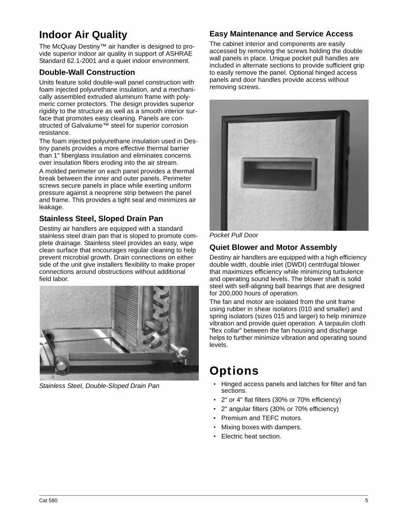
Mixing Section OptionOptional mixing section with low leak dampers are available for applications where both return and fresh air are delivered directly to the unit.
Mixing Section Options with Dampers
Electric Heat OptionAn optional electric heating element is available for installation at the discharge end of the Destiny air han-dler to provide reheat.
4 Cat 580
Indoor Air QualityThe McQuay Destiny™ air handler is designed to pro-vide superior indoor air quality in support of ASHRAE Standard 62.1-2001 and a quiet indoor environment.
Double-Wall ConstructionUnits feature solid double-wall panel construction with foam injected polyurethane insulation, and a mechani-cally assembled extruded aluminum frame with poly-meric corner protectors. The design provides superior rigidity to the structure as well as a smooth interior sur-face that promotes easy cleaning. Panels are con-structed of Galvalume™ steel for superior corrosion resistance. The foam injected polyurethane insulation used in Des-tiny panels provides a more effective thermal barrier than 1" fiberglass insulation and eliminates concerns over insulation fibers eroding into the air stream.A molded perimeter on each panel provides a thermal break between the inner and outer panels. Perimeter screws secure panels in place while exerting uniform pressure against a neoprene strip between the panel and frame. This provides a tight seal and minimizes air leakage.
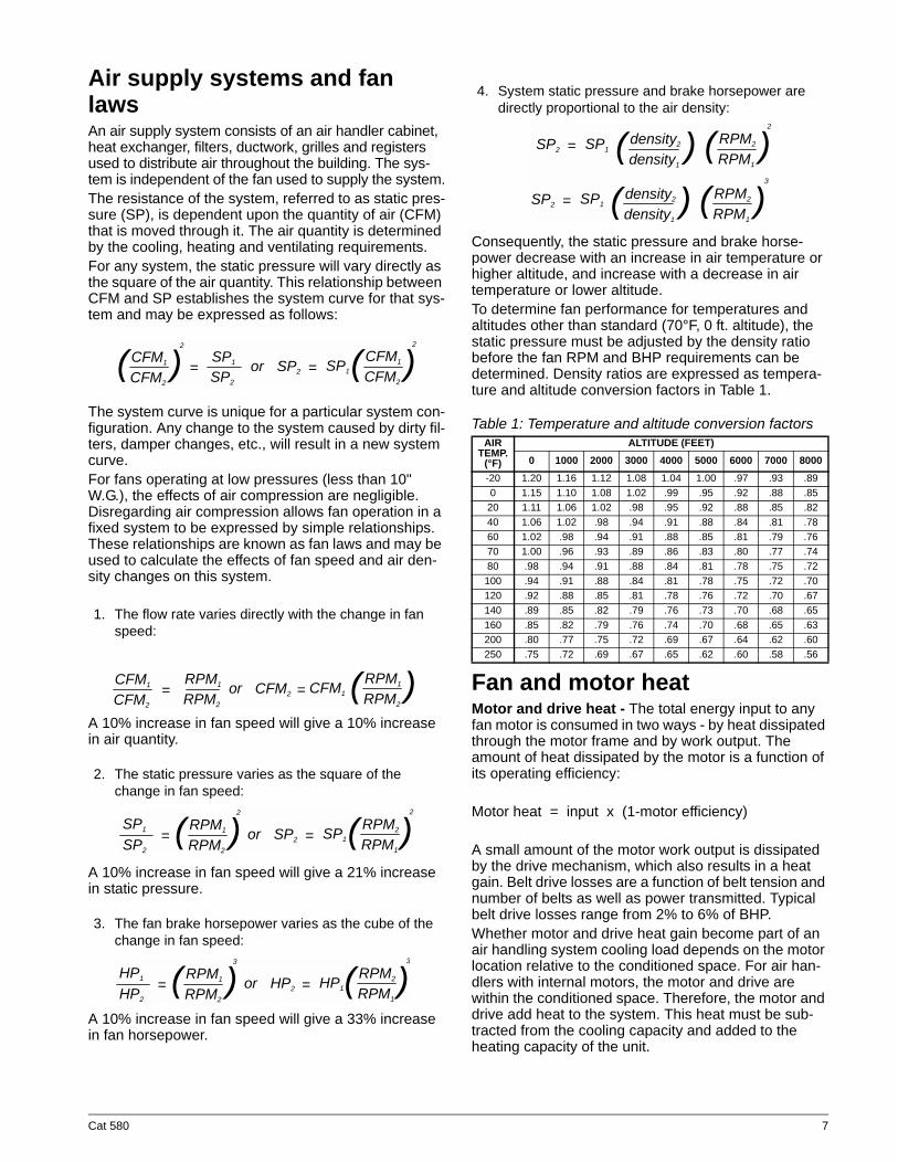
Stainless Steel, Sloped Drain PanDestiny air handlers are equipped with a standard stainless steel drain pan that is sloped to promote com-plete drainage. Stainless steel provides an easy, wipe clean surface that encourages regular cleaning to help prevent microbial growth. Drain connections on either side of the unit give installers flexibility to make proper connections around obstructions without additional field labor.
Stainless Steel, Double-Sloped Drain Pan
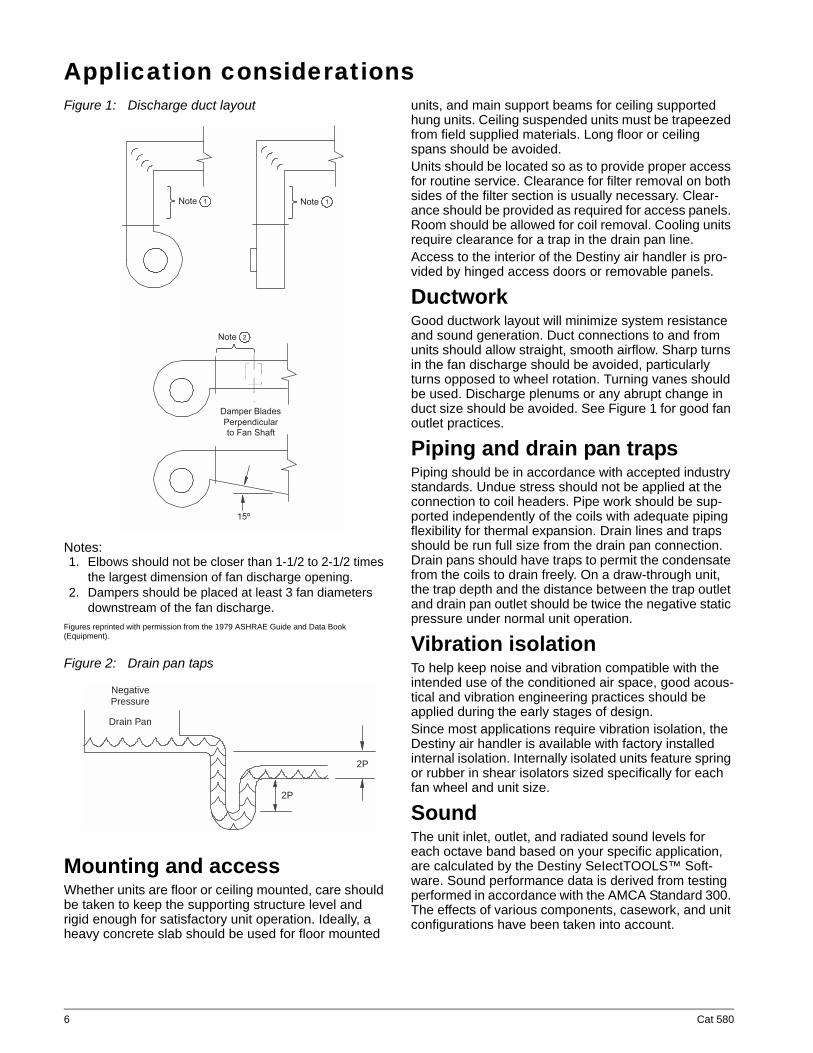
Easy Maintenance and Service AccessThe cabinet interior and components are easily accessed by removing the screws holding the double wall panels in place. Unique pocket pull handles are included in alternate sections to provide sufficient grip to easily remove the panel. Optional hinged access panels and door handles provide access without removing screws.
Pocket Pull Door
Quiet Blower and Motor AssemblyDestiny air handlers are equipped with a high efficiency double width, double inlet (DWDI) centrifugal blower that maximizes efficiency while minimizing turbulence and operating sound levels. The blower shaft is solid steel with self-aligning ball bearings that are designed for 200,000 hours of operation. The fan and motor are isolated from the unit frame using rubber in shear isolators (010 and smaller) and spring isolators (sizes 015 and larger) to help minimize vibration and provide quiet operation. A tarpaulin cloth "flex collar" between the fan housing and discharge helps to further minimize vibration and operating sound levels.
Options• Hinged access panels and latches for filter and fan
sections.• 2" or 4" flat filters (30% or 70% efficiency)• 2" angular filters (30% or 70% efficiency)• Premium and TEFC motors.• Mixing boxes with dampers.• Electric heat section.
Cat 580 5
Application considerationsFigure 1: Discharge duct layout
Notes:1. Elbows should not be closer than 1-1/2 to 2-1/2 times
the largest dimension of fan discharge opening.2. Dampers should be placed at least 3 fan diameters
downstream of the fan discharge.Figures reprinted with permission from the 1979 ASHRAE Guide and Data Book (Equipment).
Figure 2: Drain pan taps
Mounting and accessWhether units are floor or ceiling mounted, care should be taken to keep the supporting structure level and rigid enough for satisfactory unit operation. Ideally, a heavy concrete slab should be used for floor mounted
units, and main support beams for ceiling supported hung units. Ceiling suspended units must be trapeezed from field supplied materials. Long floor or ceiling spans should be avoided.Units should be located so as to provide proper access for routine service. Clearance for filter removal on both sides of the filter section is usually necessary. Clear-ance should be provided as required for access panels. Room should be allowed for coil removal. Cooling units require clearance for a trap in the drain pan line.Access to the interior of the Destiny air handler is pro-vided by hinged access doors or removable panels.
DuctworkGood ductwork layout will minimize system resistance and sound generation. Duct connections to and from units should allow straight, smooth airflow. Sharp turns in the fan discharge should be avoided, particularly turns opposed to wheel rotation. Turning vanes should be used. Discharge plenums or any abrupt change in duct size should be avoided. See Figure 1 for good fan outlet practices.
Piping and drain pan trapsPiping should be in accordance with accepted industry standards. Undue stress should not be applied at the connection to coil headers. Pipe work should be sup-ported independently of the coils with adequate piping flexibility for thermal expansion. Drain lines and traps should be run full size from the drain pan connection. Drain pans should have traps to permit the condensate from the coils to drain freely. On a draw-through unit, the trap depth and the distance between the trap outlet and drain pan outlet should be twice the negative static pressure under normal unit operation.
Vibration isolationTo help keep noise and vibration compatible with the intended use of the conditioned air space, good acous-tical and vibration engineering practices should be applied during the early stages of design.Since most applications require vibration isolation, the Destiny air handler is available with factory installed internal isolation. Internally isolated units feature spring or rubber in shear isolators sized specifically for each fan wheel and unit size.
SoundThe unit inlet, outlet, and radiated sound levels for each octave band based on your specific application, are calculated by the Destiny SeIectTOOLS™ Soft-ware. Sound performance data is derived from testing performed in accordance with the AMCA Standard 300. The effects of various components, casework, and unit configurations have been taken into account.
� � � � � � � � � �
� � � � � � � � � � � �
� � � � � �
� � �
� � � � � � � �
� � � �
Drain Pan
2P
2P
NegativePressure
6 Cat 580
Air supply systems and fan lawsAn air supply system consists of an air handler cabinet, heat exchanger, filters, ductwork, grilles and registers used to distribute air throughout the building. The sys-tem is independent of the fan used to supply the system.The resistance of the system, referred to as static pres-sure (SP), is dependent upon the quantity of air (CFM) that is moved through it. The air quantity is determined by the cooling, heating and ventilating requirements.For any system, the static pressure will vary directly as the square of the air quantity. This relationship between CFM and SP establishes the system curve for that sys-tem and may be expressed as follows:
The system curve is unique for a particular system con-figuration. Any change to the system caused by dirty fil-ters, damper changes, etc., will result in a new system curve.For fans operating at low pressures (less than 10" W.G.), the effects of air compression are negligible. Disregarding air compression allows fan operation in a fixed system to be expressed by simple relationships. These relationships are known as fan laws and may be used to calculate the effects of fan speed and air den-sity changes on this system.
1. The flow rate varies directly with the change in fan speed:
A 10% increase in fan speed will give a 10% increase in air quantity.
2. The static pressure varies as the square of the change in fan speed:
A 10% increase in fan speed will give a 21% increase in static pressure.
3. The fan brake horsepower varies as the cube of the change in fan speed:
A 10% increase in fan speed will give a 33% increase in fan horsepower.
4. System static pressure and brake horsepower are directly proportional to the air density:
Consequently, the static pressure and brake horse-power decrease with an increase in air temperature or higher altitude, and increase with a decrease in air temperature or lower altitude.To determine fan performance for temperatures and altitudes other than standard (70°F, 0 ft. altitude), the static pressure must be adjusted by the density ratio before the fan RPM and BHP requirements can be determined. Density ratios are expressed as tempera-ture and altitude conversion factors in Table 1.
Table 1: Temperature and altitude conversion factors
Fan and motor heatMotor and drive heat - The total energy input to any fan motor is consumed in two ways - by heat dissipated through the motor frame and by work output. The amount of heat dissipated by the motor is a function of its operating efficiency:
Motor heat = input x (1-motor efficiency)
A small amount of the motor work output is dissipated by the drive mechanism, which also results in a heat gain. Belt drive losses are a function of belt tension and number of belts as well as power transmitted. Typical belt drive losses range from 2% to 6% of BHP.Whether motor and drive heat gain become part of an air handling system cooling load depends on the motor location relative to the conditioned space. For air han-dlers with internal motors, the motor and drive are within the conditioned space. Therefore, the motor and drive add heat to the system. This heat must be sub-tracted from the cooling capacity and added to the heating capacity of the unit.
CFM1 CFM1SP1
SP2
SP2 SP1CFM2
2 2
CFM2= =or( () )
CFM1 RPM1RPM1
RPM2
CFM2 CFM1CFM2 RPM2= =or ( )
RPM1 RPM2SP1
SP2
SP2 SP1RPM2
2 2
RPM1= =or( () )
RPM1 RPM2HP1
HP2
HP2 HP1RPM2
3 3
RPM1= =or( () )
AIR TEMP.
(°F)
ALTITUDE (FEET)0 1000 2000 3000 4000 5000 6000 7000 8000
-20 1.20 1.16 1.12 1.08 1.04 1.00 .97 .93 .890 1.15 1.10 1.08 1.02 .99 .95 .92 .88 .85
20 1.11 1.06 1.02 .98 .95 .92 .88 .85 .8240 1.06 1.02 .98 .94 .91 .88 .84 .81 .7860 1.02 .98 .94 .91 .88 .85 .81 .79 .7670 1.00 .96 .93 .89 .86 .83 .80 .77 .7480 .98 .94 .91 .88 .84 .81 .78 .75 .72100 .94 .91 .88 .84 .81 .78 .75 .72 .70120 .92 .88 .85 .81 .78 .76 .72 .70 .67140 .89 .85 .82 .79 .76 .73 .70 .68 .65160 .85 .82 .79 .76 .74 .70 .68 .65 .63200 .80 .77 .75 .72 .69 .67 .64 .62 .60250 .75 .72 .69 .67 .65 .62 .60 .58 .56
RPM2
RPM2
density2
density2
SP2
SP2
SP1
SP1
RPM1
RPM1
2
density1
density1
=
=
((
((
))
))
Cat 580 7
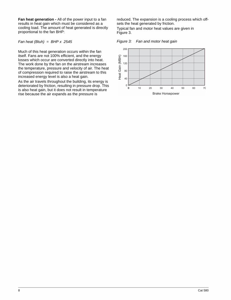
Fan heat generation - All of the power input to a fan results in heat gain which must be considered as a cooling load. The amount of heat generated is directly proportional to the fan BHP:
Fan heat (Btuh) = BHP x 2545
Much of this heat generation occurs within the fan itself. Fans are not 100% efficient, and the energy losses which occur are converted directly into heat. The work done by the fan on the airstream increases the temperature, pressure and velocity of air. The heat of compression required to raise the airstream to this increased energy level is also a heat gain.As the air travels throughout the building, its energy is deteriorated by friction, resulting in pressure drop. This is also heat gain, but it does not result in temperature rise because the air expands as the pressure is
reduced. The expansion is a cooling process which off-sets the heat generated by friction.Typical fan and motor heat values are given in Figure 3.
Figure 3: Fan and motor heat gain
�� ��� � ��!
� " "
� # "
� � "
$ "
% "
"" " � " � " & " % " � " # " ' "
� � ( � � � � � � � � ) � �
8 Cat 580
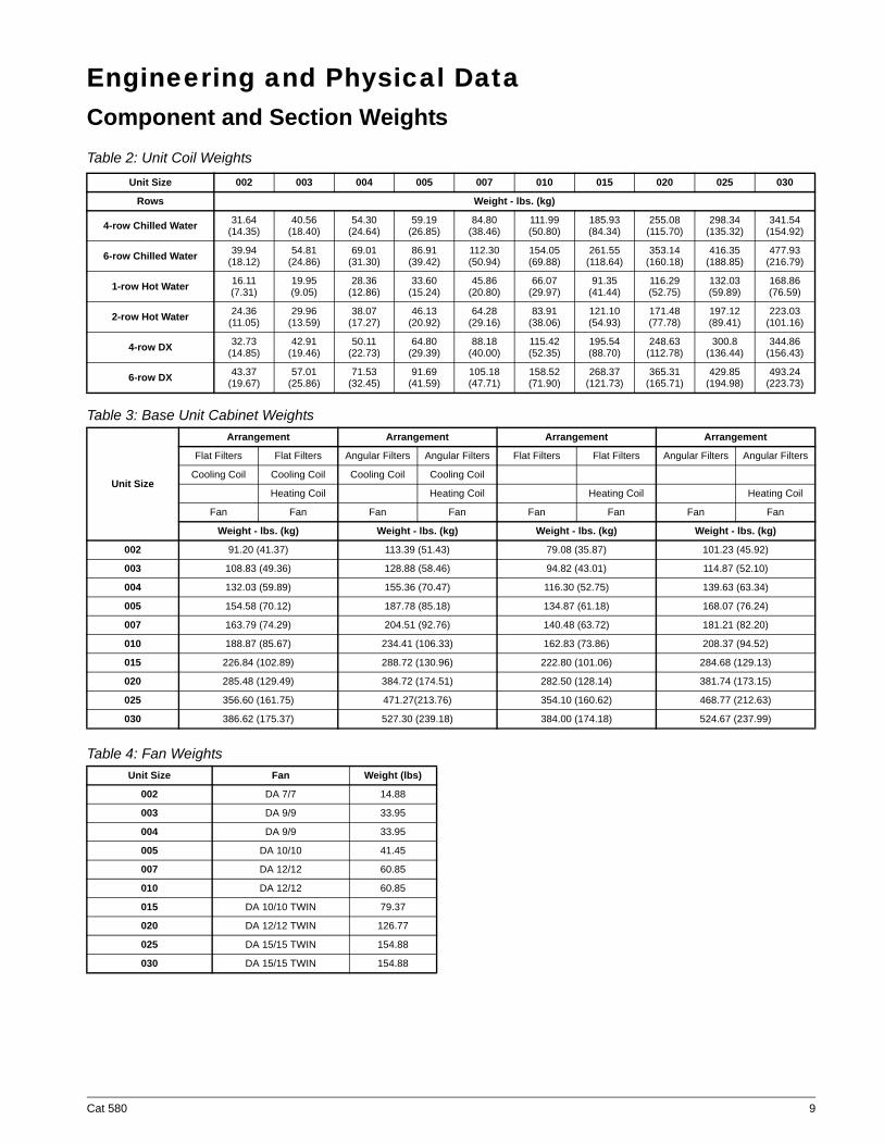
Engineering and Physical DataComponent and Section WeightsTable 2: Unit Coil Weights
Table 3: Base Unit Cabinet Weights
Table 4: Fan Weights
Unit Size 002 003 004 005 007 010 015 020 025 030
Rows Weight - lbs. (kg)
4-row Chilled Water 31.64 (14.35)
40.56 (18.40)
54.30 (24.64)
59.19 (26.85)
84.80 (38.46)
111.99(50.80)
185.93 (84.34)
255.08 (115.70)
298.34 (135.32)
341.54 (154.92)
6-row Chilled Water 39.94 (18.12)
54.81 (24.86)
69.01 (31.30)
86.91 (39.42)
112.30 (50.94)
154.05 (69.88)
261.55 (118.64)
353.14 (160.18)
416.35 (188.85)
477.93 (216.79)
1-row Hot Water 16.11 (7.31)
19.95 (9.05)
28.36 (12.86)
33.60 (15.24)
45.86 (20.80)
66.07 (29.97)
91.35 (41.44)
116.29 (52.75)
132.03 (59.89)
168.86 (76.59)
2-row Hot Water 24.36 (11.05)
29.96 (13.59)
38.07 (17.27)
46.13 (20.92)
64.28 (29.16)
83.91 (38.06)
121.10 (54.93)
171.48 (77.78)
197.12 (89.41)
223.03 (101.16)
4-row DX 32.73 (14.85)
42.91 (19.46)
50.11 (22.73)
64.80 (29.39)
88.18 (40.00)
115.42 (52.35)
195.54 (88.70)
248.63 (112.78)
300.8 (136.44)
344.86 (156.43)
6-row DX 43.37 (19.67)
57.01 (25.86)
71.53 (32.45)
91.69 (41.59)
105.18 (47.71)
158.52 (71.90)
268.37 (121.73)
365.31 (165.71)
429.85 (194.98)
493.24 (223.73)
Unit Size
Arrangement Arrangement Arrangement Arrangement
Flat Filters Flat Filters Angular Filters Angular Filters Flat Filters Flat Filters Angular Filters Angular Filters
Cooling Coil Cooling Coil Cooling Coil Cooling Coil
Heating Coil Heating Coil Heating Coil Heating Coil
Fan Fan Fan Fan Fan Fan Fan Fan
Weight - lbs. (kg) Weight - lbs. (kg) Weight - lbs. (kg) Weight - lbs. (kg)
002 91.20 (41.37) 113.39 (51.43) 79.08 (35.87) 101.23 (45.92)
003 108.83 (49.36) 128.88 (58.46) 94.82 (43.01) 114.87 (52.10)
004 132.03 (59.89) 155.36 (70.47) 116.30 (52.75) 139.63 (63.34)
005 154.58 (70.12) 187.78 (85.18) 134.87 (61.18) 168.07 (76.24)
007 163.79 (74.29) 204.51 (92.76) 140.48 (63.72) 181.21 (82.20)
010 188.87 (85.67) 234.41 (106.33) 162.83 (73.86) 208.37 (94.52)
015 226.84 (102.89) 288.72 (130.96) 222.80 (101.06) 284.68 (129.13)
020 285.48 (129.49) 384.72 (174.51) 282.50 (128.14) 381.74 (173.15)
025 356.60 (161.75) 471.27(213.76) 354.10 (160.62) 468.77 (212.63)
030 386.62 (175.37) 527.30 (239.18) 384.00 (174.18) 524.67 (237.99)
Unit Size Fan Weight (lbs)
002 DA 7/7 14.88
003 DA 9/9 33.95
004 DA 9/9 33.95
005 DA 10/10 41.45
007 DA 12/12 60.85
010 DA 12/12 60.85
015 DA 10/10 TWIN 79.37
020 DA 12/12 TWIN 126.77
025 DA 15/15 TWIN 154.88
030 DA 15/15 TWIN 154.88
Cat 580 9
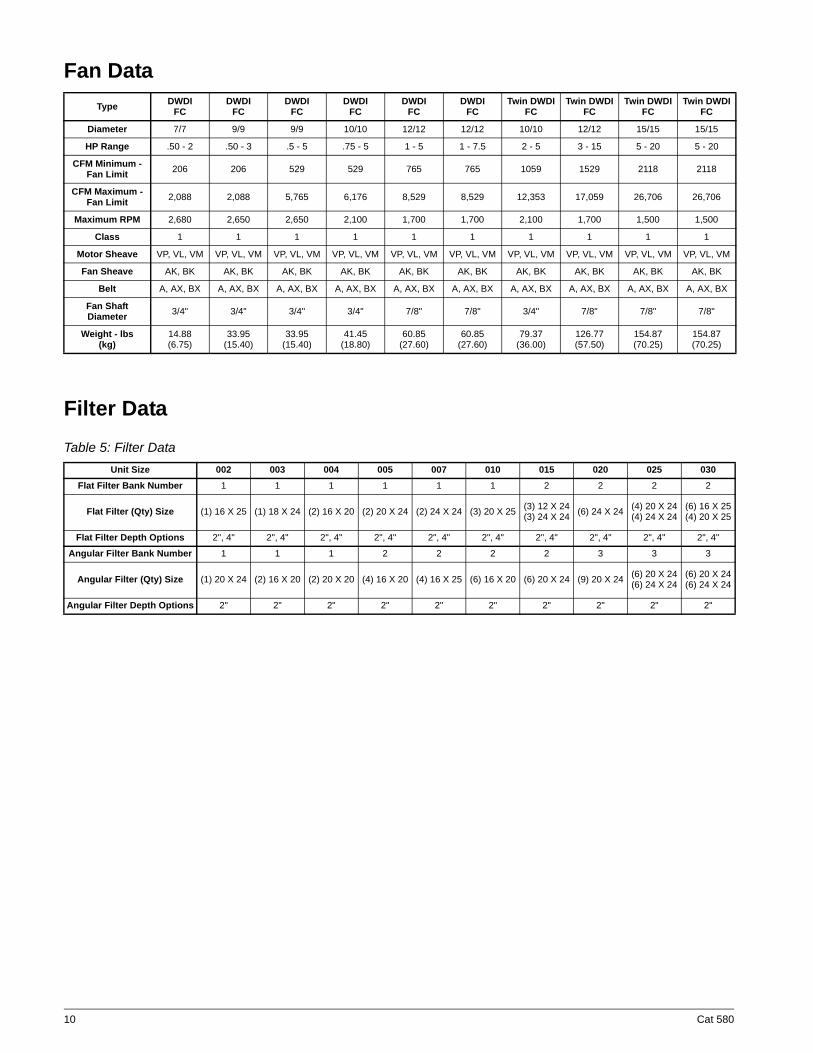
Fan Data
Filter DataTable 5: Filter Data
Type DWDI FC
DWDI FC
DWDI FC
DWDI FC
DWDI FC
DWDI FC
Twin DWDI FC
Twin DWDI FC
Twin DWDI FC
Twin DWDI FC
Diameter 7/7 9/9 9/9 10/10 12/12 12/12 10/10 12/12 15/15 15/15
HP Range .50 - 2 .50 - 3 .5 - 5 .75 - 5 1 - 5 1 - 7.5 2 - 5 3 - 15 5 - 20 5 - 20
CFM Minimum - Fan Limit 206 206 529 529 765 765 1059 1529 2118 2118
CFM Maximum - Fan Limit 2,088 2,088 5,765 6,176 8,529 8,529 12,353 17,059 26,706 26,706
Maximum RPM 2,680 2,650 2,650 2,100 1,700 1,700 2,100 1,700 1,500 1,500
Class 1 1 1 1 1 1 1 1 1 1
Motor Sheave VP, VL, VM VP, VL, VM VP, VL, VM VP, VL, VM VP, VL, VM VP, VL, VM VP, VL, VM VP, VL, VM VP, VL, VM VP, VL, VM
Fan Sheave AK, BK AK, BK AK, BK AK, BK AK, BK AK, BK AK, BK AK, BK AK, BK AK, BK
Belt A, AX, BX A, AX, BX A, AX, BX A, AX, BX A, AX, BX A, AX, BX A, AX, BX A, AX, BX A, AX, BX A, AX, BX
Fan Shaft Diameter 3/4" 3/4" 3/4" 3/4" 7/8" 7/8" 3/4" 7/8" 7/8" 7/8"
Weight - lbs (kg)
14.88 (6.75)
33.95 (15.40)
33.95 (15.40)
41.45 (18.80)
60.85 (27.60)
60.85 (27.60)
79.37 (36.00)
126.77 (57.50)
154.87 (70.25)
154.87(70.25)
Unit Size 002 003 004 005 007 010 015 020 025 030Flat Filter Bank Number 1 1 1 1 1 1 2 2 2 2
Flat Filter (Qty) Size (1) 16 X 25 (1) 18 X 24 (2) 16 X 20 (2) 20 X 24 (2) 24 X 24 (3) 20 X 25 (3) 12 X 24(3) 24 X 24 (6) 24 X 24 (4) 20 X 24
(4) 24 X 24(6) 16 X 25(4) 20 X 25
Flat Filter Depth Options 2", 4" 2", 4" 2", 4" 2", 4" 2", 4" 2", 4" 2", 4" 2", 4" 2", 4" 2", 4"
Angular Filter Bank Number 1 1 1 2 2 2 2 3 3 3
Angular Filter (Qty) Size (1) 20 X 24 (2) 16 X 20 (2) 20 X 20 (4) 16 X 20 (4) 16 X 25 (6) 16 X 20 (6) 20 X 24 (9) 20 X 24 (6) 20 X 24(6) 24 X 24
(6) 20 X 24(6) 24 X 24
Angular Filter Depth Options 2" 2" 2" 2" 2" 2" 2" 2" 2" 2"
10 Cat 580
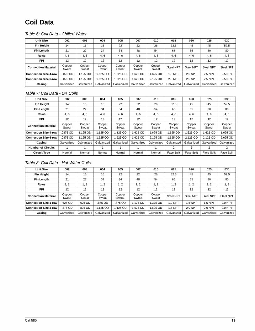
Coil DataTable 6: Coil Data - Chilled Water
Table 7: Coil Data - DX Coils
Table 8: Coil Data - Hot Water Coils
Unit Size 002 003 004 005 007 010 015 020 025 030 Fin Height 14 16 16 22 22 26 32.5 45 45 52.5
Fin Length 21 27 34 34 48 54 65 65 80 80
Rows 4, 6 4, 6 4, 6 4, 6 4, 6 4, 6 4, 6 4, 6 4, 6 4, 6
FPI 12 12 12 12 12 12 12 12 12 12
Connection Material Copper Sweat
Copper Sweat
Copper Sweat
Copper Sweat
Copper Sweat
Copper Sweat Steel NPT Steel NPT Steel NPT Steel NPT
Connection Size 4-row .0875 OD 1.125 OD 1.625 OD 1.625 OD 1.625 OD 1.625 OD 1.5 NPT 2.5 NPT 2.5 NPT 2.5 NPT
Connection Size 6-row .0875 OD 1.125 OD 1.625 OD 1.625 OD 1.625 OD 2.125 OD 2.0 NPT 2.5 NPT 2.5 NPT 2.5 NPT
Casing Galvanized Galvanized Galvanized Galvanized Galvanized Galvanized Galvanized Galvanized Galvanized Galvanized
Unit Size 002 003 004 005 007 010 015 020 025 030 Fin Height 14 16 16 22 22 26 32.5 45 45 52.5
Fin Length 21 27 34 34 48 54 65 65 80 80
Rows 4, 6 4, 6 4, 6 4, 6 4, 6 4, 6 4, 6 4, 6 4, 6 4, 6
FPI 12 12 12 12 12 12 12 12 12 12
Connection Material Copper Sweat
Copper Sweat
Copper Sweat
Copper Sweat
Copper Sweat
Copper Sweat
Copper Sweat
Copper Sweat
Copper Sweat
Copper Sweat
Connection Size 4-row .0875 OD 1.125 OD 1.125 OD 1.125 OD 1.625 OD 1.625 OD 1.625 OD 1.625 OD 1.625 OD 1.625 OD
Connection Size 6-row .0875 OD 1.125 OD 1.625 OD 1.625 OD 1.625 OD 2.125 OD 1.625 OD 2.125 OD 2.125 OD 2.625 OD
Casing Galvanized Galvanized Galvanized Galvanized Galvanized Galvanized Galvanized Galvanized Galvanized Galvanized
Number of Circuits 1 1 1 1 1 1 2 2 2 2
Circuit Type Normal Normal Normal Normal Normal Normal Face Split Face Split Face Split Face Split
Unit Size 002 003 004 005 007 010 015 020 025 030Fin Height 14 16 16 22 22 26 32.5 45 45 52.5
Fin Length 21 27 34 34 48 54 65 65 80 80
Rows 1, 2 1, 2 1, 2 1, 2 1, 2 1, 2 1, 2 1, 2 1, 2 1, 2
FPI 12 12 12 12 12 12 12 12 12 12
Connection Material Copper Sweat
Copper Sweat
Copper Sweat
Copper Sweat
Copper Sweat
Copper Sweat Steel NPT Steel NPT Steel NPT Steel NPT
Connection Size 1-row .625 OD .625 OD .875 OD .875 OD 1.125 OD 1.375 OD 1.0 NPT 1.5 NPT 1.5 NPT 2.0 NPT
Connection Size 2-row .875 OD .875 OD 1.125 OD 1.125 OD 1.625 OD 1.625 OD 1.5 NPT 2.0 NPT 2.0 NPT 2.0 NPT
Casing Galvanized Galvanized Galvanized Galvanized Galvanized Galvanized Galvanized Galvanized Galvanized Galvanized
Cat 580 11
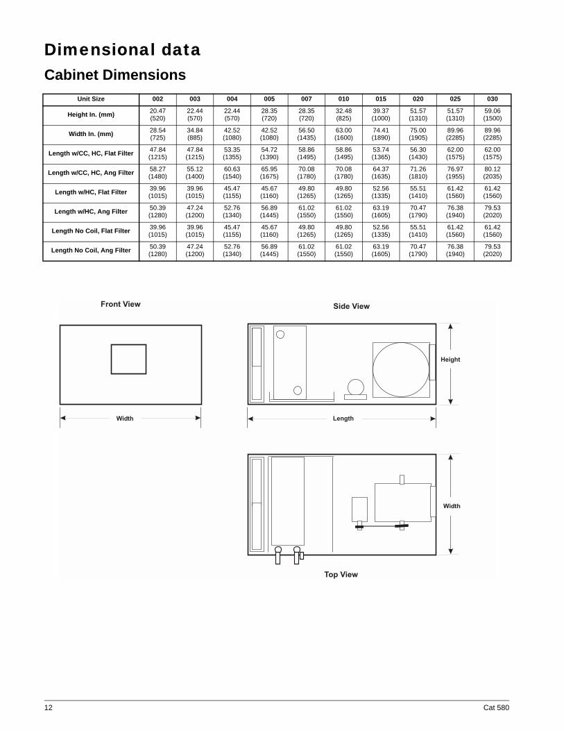
Dimensional dataCabinet Dimensions
Unit Size 002 003 004 005 007 010 015 020 025 030
Height In. (mm) 20.47 (520)
22.44 (570)
22.44 (570)
28.35 (720)
28.35 (720)
32.48 (825)
39.37 (1000)
51.57 (1310)
51.57 (1310)
59.06 (1500)
Width In. (mm) 28.54 (725)
34.84 (885)
42.52 (1080)
42.52 (1080)
56.50 (1435)
63.00 (1600)
74.41 (1890)
75.00 (1905)
89.96 (2285)
89.96 (2285)
Length w/CC, HC, Flat Filter 47.84 (1215)
47.84 (1215)
53.35 (1355)
54.72 (1390)
58.86 (1495)
58.86 (1495)
53.74 (1365)
56.30 (1430)
62.00 (1575)
62.00 (1575)
Length w/CC, HC, Ang Filter 58.27 (1480)
55.12 (1400)
60.63 (1540)
65.95 (1675)
70.08 (1780)
70.08 (1780)
64.37 (1635)
71.26 (1810)
76.97 (1955)
80.12 (2035)
Length w/HC, Flat Filter 39.96 (1015)
39.96 (1015)
45.47 (1155)
45.67 (1160)
49.80 (1265)
49.80 (1265)
52.56 (1335)
55.51 (1410)
61.42 (1560)
61.42 (1560)
Length w/HC, Ang Filter 50.39 (1280)
47.24 (1200)
52.76 (1340)
56.89 (1445)
61.02 (1550)
61.02 (1550)
63.19 (1605)
70.47 (1790)
76.38 (1940)
79.53 (2020)
Length No Coil, Flat Filter 39.96 (1015)
39.96 (1015)
45.47 (1155)
45.67 (1160)
49.80 (1265)
49.80 (1265)
52.56 (1335)
55.51 (1410)
61.42 (1560)
61.42 (1560)
Length No Coil, Ang Filter 50.39 (1280)
47.24 (1200)
52.76 (1340)
56.89 (1445)
61.02 (1550)
61.02 (1550)
63.19 (1605)
70.47 (1790)
76.38 (1940)
79.53 (2020)
Length
Height
Width
Width
Front View Side View
Top View
12 Cat 580
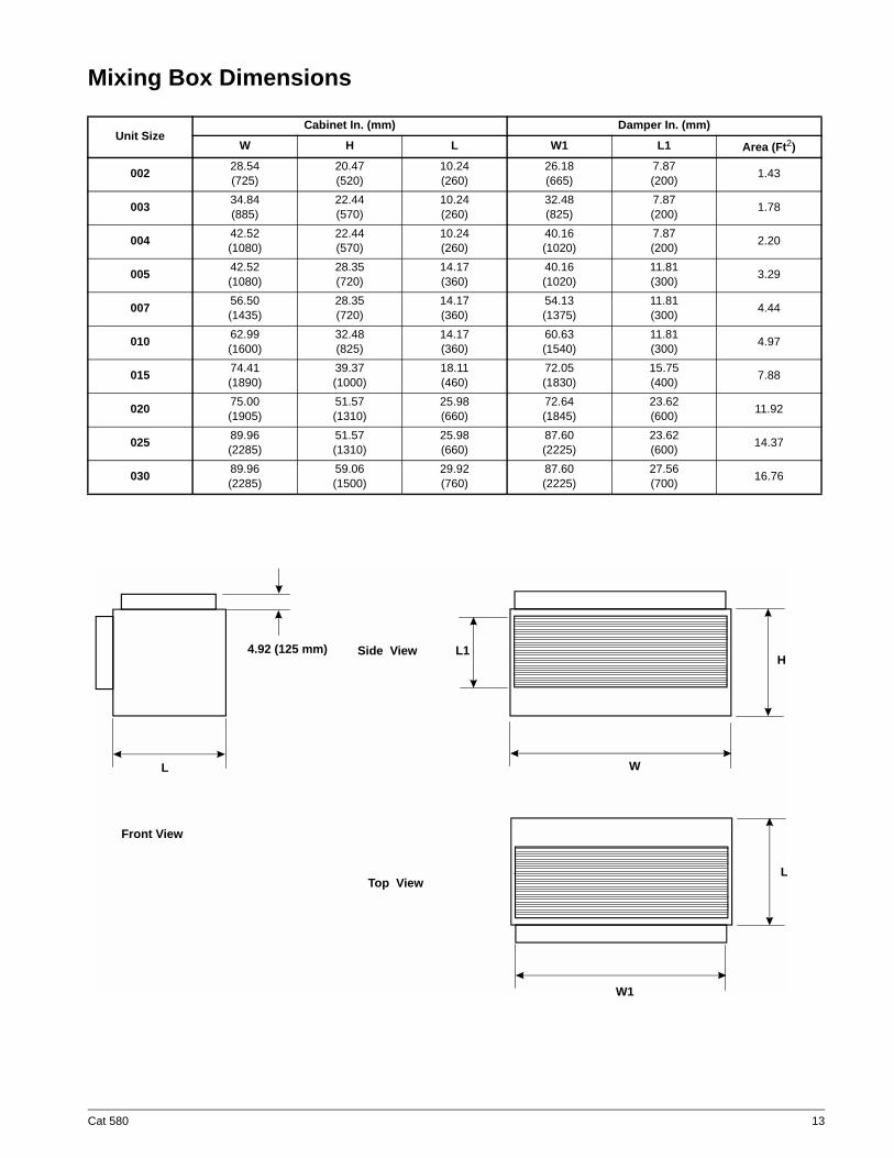
Mixing Box Dimensions
Unit SizeCabinet In. (mm) Damper In. (mm)
W H L W1 L1 Area (Ft2)
002 28.54 (725)
20.47(520)
10.24(260)
26.18(665)
7.87(200) 1.43
003 34.84(885)
22.44(570)
10.24(260)
32.48(825)
7.87(200) 1.78
004 42.52(1080)
22.44(570)
10.24(260)
40.16(1020)
7.87(200) 2.20
005 42.52(1080)
28.35(720)
14.17(360)
40.16(1020)
11.81(300) 3.29
007 56.50(1435)
28.35(720)
14.17(360)
54.13(1375)
11.81(300) 4.44
010 62.99(1600)
32.48(825)
14.17(360)
60.63(1540)
11.81(300) 4.97
015 74.41(1890)
39.37(1000)
18.11(460)
72.05(1830)
15.75(400) 7.88
020 75.00(1905)
51.57(1310)
25.98(660)
72.64(1845)
23.62(600) 11.92
025 89.96(2285)
51.57(1310)
25.98(660)
87.60(2225)
23.62(600) 14.37
030 89.96(2285)
59.06(1500)
29.92(760)
87.60(2225)
27.56(700) 16.76
4.92 (125 mm)
Front View
Side View
Top View
L1
WL
W1
L
H
Cat 580 13
Engineering guide specificationPART 1: GENERAL
1.01 SECTION INCLUDESA. Air handling units.
1.02 REFERENCESA. AFBMA 9 - Load Ratings and Fatigue Life for Ball Bearings.B. AMCA 99 - Standards Handbook.C. AMCA 210 - Laboratory Methods of Testing Fans for Rating Purposes.D. AMCA 300 - Test Code for Sound Rating Air Moving Devices.E. AMCA 500 - Test Methods for Louver, Dampers, and Shutters.F. AG.ARI 430 - Central-Station Air-Handling Units.H. ARI 435 - Application of Central-Station Air-Handling Units.I. ASTMB117 - Standard Practice for Operating Salt Spray ApparatusJ. NEMA MG1 - Motors and Generators.K. NFPA 70 - National Electrical Code.L. SMACNA - HVAC Duct Construction Standards - Metal and Flexible.M. UL 723 - Test for Surface Burning Characteristics of Building MaterialsN. UL 900 - Test Performance of Air Filter Units.O. UL 1995 - Standard for Heating and Cooling EquipmentP. UL 94 - Test for Flammability of Plastic Materials for Parts in Devices and Appliances
1.03 SUBMITTALSA Shop Drawings: Indicate assembly, unit dimensions, weight loading, required clearances, construction details, field
connection details, and electrical characteristics and connection requirements. Computer generated fan curves foreach air handling unit shall be submitted with specific design operating point noted. A computer generated psycho-metric chart shall be submitted for each cooling coil with design points and final operating point clearly noted.
B. Product Data:1.Provide literature that indicates dimensions, weights, capacities, ratings, fan performance, finishes
of materials, and electrical characteristics and connection requirements.2. Provide data of filter media, filter performance data, filter assembly, and filter frames.3. Manufacturer's Installation Instructions.
1.04 OPERATION AND MAINTENANCE DATAA. Maintenance Data: Include instructions for lubrication, filter replacement and motor and drive replacement.
1.05 QUALIFICATIONSA. Manufacturer: Company specializing in manufacturing the Products specified in this section with minimum five
years documented experience, which issues complete catalog data on total product.1.06 DELIVERY, STORAGE, AND HANDLING
A. Deliver, store, protect and handle products to site.B. Accept products on site on factory-installed shipping skids. Inspect for damage.C. Store in clean dry place and protect from weather and construction traffic. Handle carefully to avoid damage to com-
ponents, enclosures, and finish.1.07 ENVIRONMENTAL REQUIREMENTS
A. Do not operate units for any purpose, temporary or permanent, until ductwork is clean, filters are in place, bearingslubricated, and fan has been test run under observation.
14 Cat 580
PART 2: PRODUCTS2.01 MANUFACTURERS
A. The following manufacturers are approved for use. No substitutions will be permitted.1. McQuay2. ETI3. Greenheck
2.02 CASING
A. Unit shall have corrosion resistant casing design consisting of an aluminum frame with 1" thick, double wall panels.Extruded aluminum frame and polymeric corners pieces are required for casing protection and rigidity. Unit panelsshall consist of injected polystyrene insulation sandwiched between Zintro-Alum exterior and interior sheets.Formed "thermal break" panels will have a plastic molded edge to eliminate inner and outer panels from contactingeach other. Panels are fastened to frame with perimeter screws that hold panels in place with a neoprene gasket in-between the panel and the frame to prevent thermal bridging from the interior to the exterior of the unit.
B. Removable Panels on both sides of unit shall provide full access to unit interior. Blower access panels shall includehandle to assist in removing panel [opposite driveside].
C. [Opt.] Hinged Access Doors to fan and filter sections on drive side [Access Doors on both sides of air handler.].Access doors shall have the same construction as air handler panels.
D. Construct drain pans from stainless steel with sloping pitch to drain connection to allow for condensate drainage.Drain Pan is positioned above 1" thick insulated double wall panel. Condensate drain connections shall be providedon both sides of drain pan.
2.03 SUPPLY FAN
A. Provide DWDI forward-curved supply fans. Fan assemblies including fan, motor and sheaves shall be dynamicallybalanced by the manufacturer on all three planes and at all bearing supports. Manufacturer must ensure maximumfan RPM is below the first critical speed.
B. Bearings shall be self-aligning, grease lubricated, ball or roller bearings.
C. Fan and motor assembly shall be mounted on vibration type isolators inside cabinetry.
D. Units shall be certified in accordance with the central station air handling units certification program, which is basedon ARI Standard 430.
2.04 BEARINGS AND DRIVESA. Bearings: Basic load rating computed in accordance with AFBMA - ANSI Standards, L-50 life at 200,000 hours
heavy duty pillow block type, self-aligning, grease-lubricated ball bearings.B. Shafts shall be solid, hot rolled steel, ground and polished, keyed to shaft, and protectively coated with lubricating
oil. Hollow shafts are not acceptable.C. V-Belt drives shall be cast iron or steel sheaves, dynamically balanced, bored to fit shafts and keyed. Variable
and adjustable pitch sheaves selected so required RPM is obtained with sheaves set at mid-position and ratedbased on motor horsepower. Contractor to furnish fixed sheaves at final RPM as determined by balancing con-tractor.
2.05 ELECTRICAL
A. Motors: provide (ODP)(TEFC) type with (EPACT) (premium) efficiency. Electrical characteristics shall be asshown in schedule.
2.07 COOLING AND HEATING COIL SECTIONS
A. Provide access to coils from (opposite connection side) of unit for service and cleaning. Enclose coil headers and returnbends fully within unit casing. Drain and vent connections shall be provided exterior to unit casing. Coil connections mustbe factory sealed with grommets on exterior of unit casing to minimize air leakage and condensation inside panel assem-bly.
Cat 580 15
B. Water Coils:
1. Fins shall have full drawn collars to provide a continuous surface cover over the entire tube for maximum heat trans-fer. Tubes shall be mechanically expanded into the fins to provide a continuous primary to secondary compressionbond over the entire finned length for maximum heat transfer rates. Bare copper tubes shall not be visible betweenfins.
2. Coil tubes shall be seamless copper, expanded into fins, brazed at joints. 3. Water coils shall be provided with headers of seamless copper tubing with intruded tube holes to permit expansion
and contraction without creating undue stress or strain. Coil connections shall be carbon steel or copper with connec-tion size to be determined by manufacturer based upon the most efficient coil circuiting. Vent connections provided atthe highest point to assure proper venting. Drain connections shall be provided at the lowest point for proper drain-age.
4. Coil casings shall be a formed channel frame of galvanized steel.
D. Refrigerant Coils:
1. Coils designed for use with Refrigerant [R-22] [R-134a] [other]. Fins shall be of aluminum with full drawn collars toprovide a continuous surface cover over the entire tube for maximum heat transfer. Tubes shall be mechanicallyexpanded into the fins to provide a continuous primary-to-secondary compression bond over the entire finned lengthfor maximum heat transfer rates. Bare copper tube shall not be visible between fins.
2. Sweat type copper suction connections located at the bottom of the suction headers for gravity oil drainage. Pres-sure type liquid distributors used. Coils shall be tested with 315 pounds air pressure, and suitable for 250 psig work-ing pressure. Coils shall be Underwriters Laboratories, Inc. listed.
2.08 FILTERSA. [Flat] [Angle] arrangement with (2") (4") deep pleated panel filters.B. Filters shall be MERV 6 (30%) [or MERV 8 (70%)]C. Filter media shall be UL 900 listed, Class I or Class II.
2.09 ADDITIONAL SECTIONS[Opt.] Mixing Box consists of the same construction as described for "Unit Casing". Section should include factory mountedoutside and return air dampers with aluminum blades and frame.
PART 3: EXECUTION
3.01 INSTALLATIONA. Install in accordance with manufacturer’s instructions.
16 Cat 580

© 2003 McQuay International • www.mcquay.com • 800-432-1342
This document contains the most current product information as of this printing. For the most up-to-dateproduct information, please go to www.mcquay.com.


![[XLS] · Web view580 580 580 580 580 580 580 580 580 580 580 580 580 580 580 580 580 580 580 580 580 580 580 580 580 580 580 580 580 580 580 580 580 580 580 580 580 580 580 580 580](https://img.pdfslide.net/doc/110x75/5ba1448d09d3f2666b8bff1c/xls-web-view580-580-580-580-580-580-580-580-580-580-580-580-580-580-580-580.jpg)