Embed Size (px)
Citation preview
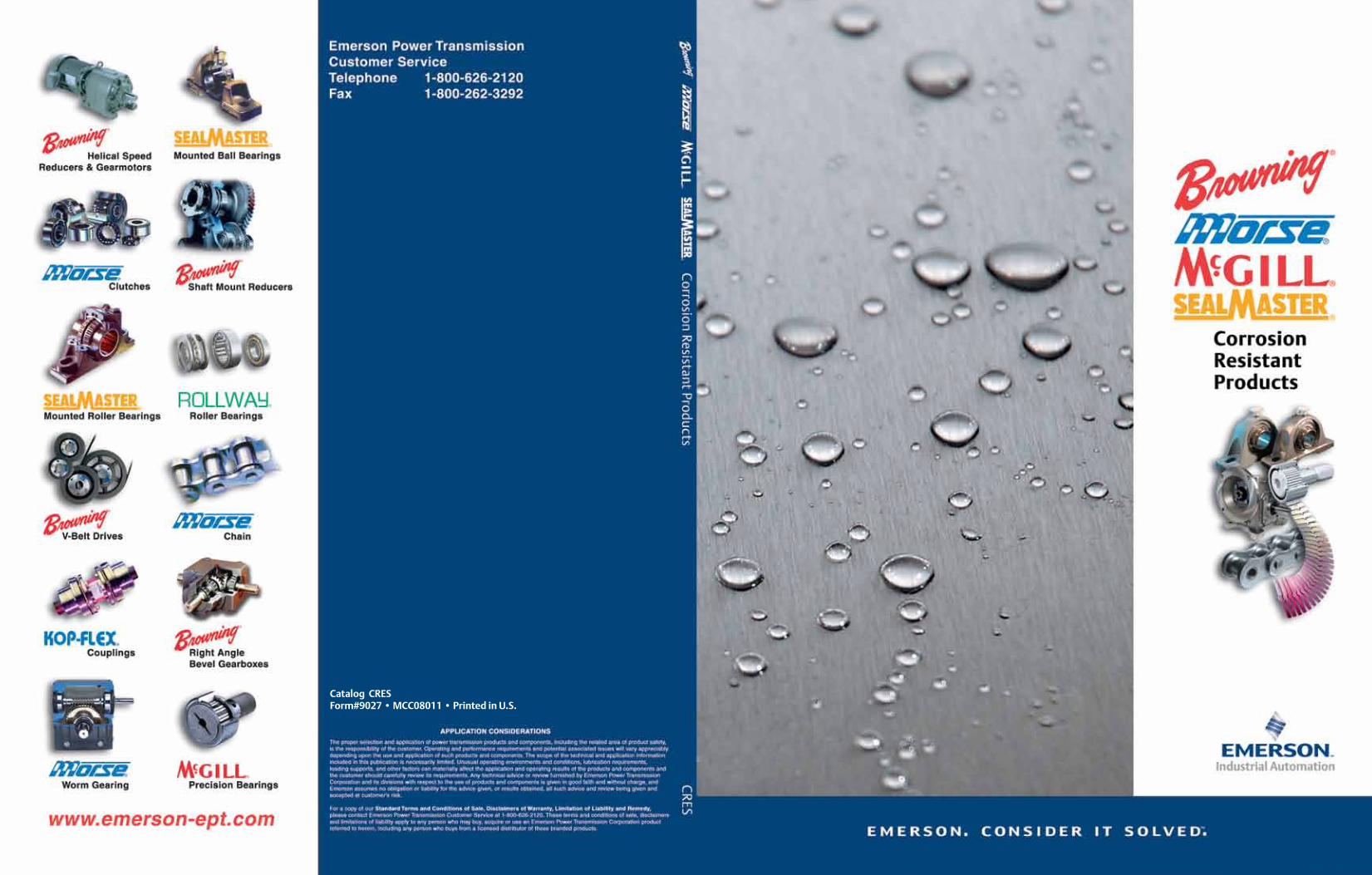
Catalog CRESForm#9027 • MCC08011 • Printed in U.S.

2 3
Corrosion Resistant Engineered Solutions
EMERSON POWER TRANSMISSION
In an environment of increased operational requirements and tough
regulatory guidelines, today’s bearings and power transmission products are
exposed to a host of demanding conditions. Such conditions may include
corrosive cleaning agents, high pressure washdown and a wide array of
environmental factors that can negatively impact performance. Overall, a
balance of material strength and corrosion resistance, sealing and lubrication.
Tough Environments, Durable Solutions
CRES — Corrosion Resistant Engineered Solutions Introducing CRES from Emerson Power Transmission – a comprehensive
line of corrosion resistant power transmission products. CRES products are
engineered to perform in corrosive and contaminated environments.
Topveyor® is a registered trademark of Emerson Power Transmission Manufacturing, L.P.
*The trade names, trademarks and/or registered trademarks of others used herein for comparison purposes, are NOT owned or controlled by Emerson Power Transmission Corporation and are believed to be owned by the following companies: Matveyor: Regina-Emerson, Ultop: UCC Corp.
The Emerson logo is a trademark and a service mark of Emerson Electric Co.© Emerson Power Transmission Manufacturing, L. P. or affiliates 2007. All rights reserved.
CRES PRODUCTS
Bearing ProductsTechnical Overview and Selection ............................. 8-13McGill® CRES Cam Followers ................................... 14-19Sealmaster® CRES Mounted Roller Bearings ............ 20-29Browning® and SealmasterCRES Mounted Ball Bearings ................................... 30-99
Gearing ProductsMorse® Stainless Steel Raider® PlusWorm Gear Reducers ........................................... 90 -119
Expanded, Corrosion-Resistant CoatingsFor Browning Helical Reducers and GearmotorsCorro-Duty Gray and Corro-Duty White ............. 110-111
Component ProductsCRES Components .............................................. 112-120Morse CRES Roller Chain .................................... 114-115Morse CRES Conveying Components .................. 116-117Morse Gripper Chain ........................................... 118-119Browning Torque Overload Device ............................. 120Morse Clutch ............................................................. 120

4 5
Corrosion Resistant Engineered Solutions
EMERSON POWER TRANSMISSION
In an efficient, high speed filling process, product failure can cost thousands of dollars in downtime. Emerson Power Transmission offers solutions that perform in wet environments. This high performance platform, combined with specialized sealing, greases and anti-corrosion materials and coatings, reduces downtime in today’s competitive environment.
Bottling and Canning
Tough Environments, Durable Solutions
Focus Industries • Meat and Poultry • Bakeries and Snack Foods • Bottling and Canning • Pharmaceuticals • Car Washes • Pulp and Paper • Marine
Applications
Meat and PoultryEven the smallest amount of corrosion can shut down production so Emerson
Power Transmission has created specific solutions that are HACCP-
friendly.
Bakeries and Snack FoodsHeat, flour and food particles make for a
tough manufacturing environment.Emerson Power Transmission offers
products with specialized tolerancesto accommodate for the expansion
and contraction of materialscommon to high
temperaturefood
processing.

6 7
Corrosion Resistant Engineered Solutions
BEARINGS
®
®
® CRES Bearings
The Emerson Power Transmission CRES bearing offering addresses various industries and applications by providing multiple solutions utilizing a variety of materials and sealing elements. CRES bearings assist customers in meeting HACCP (Hazardous Analysis and Critical Control Point) procedures and stringent plant cleaning requirements including both CIP (Clean in Place) and SIP (Steam in Place).
CRES Bearings
As environmental and performance requirements change from application to application a single bearing design may not be the most economical choice. Emerson Power Transmission’s family of CRES bearing products can help you align the optimal solution to specific requirements. This flexibility of choice will assist in meeting food safety industry requirements and reduce your total operating cost.
The Sealmaster, Browning and McGill family of CRES bearing products is your answer to your corrosion resistance problems.
CRES — Flexibility of Choice
Bearing ProductsCorrosion Basics ......................................................... 8-9Material Basics ........................................................ 10-11Product Selection ................................................... 12-13
CRES Cam FollowersMcGill CRES CAMROL® ............................................ 14-19
CRES Mounted Roller BearingsSealmaster RPB-CR ................................................. 20-29
CRES Mounted Mounted Ball BearingsSealmaster CR Gold ................................................ 30-35Sealmaster PN Gold™ ............................................. 36-57Browning CRES CZ .................................................. 58-63Browning CRES CS .................................................. 64-69Browning CRES SS .................................................. 70-75Sealing and Sealing Accessories .............................. 76-79Housing Material .................................................... 80-82
Lubrication ............................................................. 94-95Speed and Load Charts ........................................... 96-98

8 9
Corrosion Resistant Engineered Solutions
BEARINGS
®
®
® Corrosion Basics
Standard Chemical pHThe chart below offers general guidelines on the pH level of common foods, beverages and chemicals to help you choose an appropriate bearing material.
Corrosion is the deterioration of a materials properties due to a chemical or electrochemical reaction with it’s environment. Corrosion is a leading cause of bearing problems.
Bearing replacement due to corrosion can be based on visual or performance factors. • Visual factors relate to the aesthetics of the bearing and potential for corrosion runoff onto the
product being processed. In certain applications this is unacceptable due to health or cleanliness standards.
• Performance factors relate to how excessive corrosion may prevent the bearing from rotating properly. The corrosion that occurs can lead to seal degradation, contamination ingress or internal component wear leading to bearing seizure.
Why Does Corrosion Occur?
The rate of corrosion depends on application conditions and material.ChemicalsBoth the chemical composition and/or pH levels can impact the rate of corrosion. Consideration must be given to both process and cleaning materials that come in contact with the bearing.
Contact MethodThe type of contact a material has with the chemical can have a significant impact on the rate of corrosion. Whether a material is exposed to high-pressure spray, light flow or a fog condition, the corrosion rate can vary greatly.
Environment and AtmosphereIncreased levels of humidity, oxygen content and temperature can accelerate corrosion rates. In addition, cycles of equipment operation can impact overall bearing performance.
Strong Acid0-3 pH
Mild Acid4-6 pH
Neutral7 pH
Mild Base8-10 pH
Strong Base11-14 pH
Hydrochloric Acid Tomatoes Distilled Water Seawater AmmoniaHydrofluoric Acid Boric Acid Shrimp Calcium Chloride Sodium Silicate
Battery Acid Hydrogen Sulfide Corn Oil Soaps, Shampoo Sodium CyanideSulfuric Acid Beer Sugar Sodium Acetate Sodium Carbonate
Nitric Acid Ammonium Chloride Trichloroethylene Sodium Bicarbonate Sodium PhosphatePhosphoric Acid Rain Water Acetone Baking Soda Chlorine
Vinegar Coffee Blood Detergents BleachHydrogen Peroxide Meat, Pork, Poultry Sodium Sulphate Sodium Hypochlorite
Acetic Acid Dairy Products Sodium Sulfite Caustic SodaSoft Drinks Sodium Chloride, Salt Magnesium Hydroxide Sodium Hydroxide, LyeCitric Acid Seafood Drain CleanerFruit Juices Fertilizer Potassium HydroxidePickle Brine VegetablesLactic Acid Bread
WineSport DrinksBenzoic Acid

10 11
Corrosion Resistant Engineered Solutions
BEARINGS
®
®
® Material Basics
Materials were exposed for 8 hours to the test chemical followed by a dry period of 16 hours. This test was repeated six times for acid condition and twice for basic condition.
Acid test condition: citric acid, pH 2, 48 hours chemical exposure.Basic test condition: chlorine bleach, 6% concentration, pH 12, 16 hours chemical exposure.
Material Basic TestAcid Test
CRES bearing products utilize a variety of materials and coatings. Each material offers various levels of load capacity and resistance to wear and corrosion. To better understand visual performance characteristics, EPT engineers have tested these materials in various conditions. Shown below are the materials in an untested state and after exposure to an acid and basic chemical.
Material Basics
Material Basic TestAcid Test
*TEFLON is a registered trademark of the DuPont Company.
52100 Bearing Steel • Common bearing material• Good load capacity and wear resistance• Minimal corrosion resistance
Black Oxide• Common bearing steel with oxidized surface• Marginal improvement to corrosion resistance
compared to 52100 bearing steel• Minimal corrosion resistance compared to
coatings or stainless steel
Zinc Dichromate Coating• 52100 bearing steel coated with zinc
dichromate• If scratched or damaged, the coating will
sacrificially corrode to protect the base material• Zinc coatings are more prone to deteriorate
then barrier coatings
Thin Dense Chrome (TDC)• 52100 bearing steel with a thin barrier coating• Good wear and abrasion resistance• May not hold up as well as thicker coatings over
time
Nickel with TEFLON® (PTFE)• 52100 bearing steel with a thin barrier coating
of nickel with thick PTFE overcoat• Holds up better than thinner coatings over
time• If scratched, barrier coating may not protect
base material
Phosphorus Nickel• 52100 bearing steel with a thick barrier
coating of high phosphorus electroless nickel• Holds up better than thinner coatings over
time• If scratched, barrier coatings may not protect
base material
400 Series Stainless Steel• Martensitic stainless steel• Hardens for good load capacity and wear
resistance• Not as durable as 52100 bearing steel or as
corrosion resistant as 300 Series stainless steel
300 Series Stainless Steel• Austenitic stainless steel• Excellent corrosion resistance• Cannot be hardened for improved load
capacity or wear resistance

12 13
Corrosion Resistant Engineered Solutions
BEARINGS
®
®
® Product Selection
Legend: = Worst = Best
Values listed in the mounted ball, mounted roller and cam follower charts are general guidelines to assist in bearing selection, as compared against the other products listed in the range. They are not comparable across product lines. User testing and evaluation is strongly suggested to determine which product will best meet specific conditions and requirements.
*The overall corrosion resistance values listed are general guideline on material performance based on our laboratory testing. Material performance can vary based on the specific chemicals used, contact method and environmental factors and cannot be reliably predicted for every condition combination. For more information please refer to EPT Bearing Application Engineering at 219-465-2211.
For load and speed limitations refer to pages 17 and 19 for cam followers and pages 96-98 for mounted bearings.
(a) RPB Inner Ring 52100 steel.
Cam Follower
Mounted Roller Bearing
Mounted Ball Bearing
Legend: = Worst = Best
b) Industry standard offers a labyrinth seal design.
**Relative load rating for mounted ball and cam followers takes into consideration life adjustments (derate factors) for bearing raceways and rolling element materials. ABMA recommends a material derate factor for 440C stainless steel. For more information on life adjustment factors refer to page 178 of Sealmaster catalog BP-97. Roller bearing relative load rating compares basic dynamic ratings at the same number of theoretical cycles.
ProductMaterial Overall Corrosion Resistance*
Inner and Outer Material
Rolling Element Material Low pH Neutral pH High pH
CAMROL Standard Black Oxide 52100 Steel 52100 Steel P P P
CRES CAMROL 440C Stainless Steel 440C Stainless Steel PPPP PPPP PPPP
ProductMaterial Overall Corrosion Resistance *
Inner and Outer Material (a)
Rolling Element Material
Housing Material Low pH Neutral pH High pH
RPB Series (Tapered Roller)
Black Oxide 52100 Steel Alloy Steel Painted Cast Iron P P P
SPB1000 Series (Spherical Roller) Alloy Steel Alloy Steel Painted Cast Iron P P P
RPB-CR Series (Tapered Roller)
Black Oxide 52100 Steel Alloy Steel Fluropolymer
Coated Cast Iron P P P P P P
ProductMaterial Overall Corrosion Resistance *
Inner and Outer Material (a)
Rolling Element Material Housing Material Low pH Neutral pH High pH
CRES CZ Zinc Dichromate Coated 52100 Steel 52100 Steel High Strength
Composite P P P P P P
CRES CS 440C Stainless Steel
440C Stainless Steel
High Strength Composite PPPP PPPP PPPP
CRES SS 440C Stainless Steel
440C Stainless Steel
304 Stainless Steel PPPP PPPP PPPP
CR GOLD Black Oxide 52100 Steel 52100 Steel 316
Stainless Steel P P P
PN GOLD (Stainless Housing)
Phosphorus Nickel Coated 52100 Steel
440C Stainless Steel
316 Stainless Steel PPPP PPP PPP
PN GOLD (Composite Housing)
Phosphorus Nickel Coated 52100 Steel
440C Stainless Steel
High Strength Composite PPPP PPP PPP
Sealing Effectiveness Unit Performance FactorsPage Number
High Pressure Spray Particle Contaminate Resistance Relative Load Ratings ** Speed Capability
PP PPP PPPPP PPP None
PPPP PPPP PPP PPP Pages 14-19
Sealing Effectiveness (b) Unit Performance FactorsPage NumberHigh Pressure Spray Particle Contaminate
Resistance Relative Load Ratings ** Housing Strength Speed Capability
PP PP PPPP PPP PPP None
P P PP PPP PPPP None
PP PP PPPP PPP PPP Pages 20-29
Sealing Effectiveness Unit Performance FactorsPage NumbersHigh Pressure Spray Particle Contaminate
Resistance Relative Load Ratings ** Housing Strength Speed Capability
PPP PP PPPPP PPP PPP Pages 70-75
PP P PPP PPP PP Pages 76-81
PP P PPP PPPPP PP Pages 82-87
P PPP PPPPP PPPPP PPPP Pages 30-35
PPPPP PPPPP PPPP PPPPP PP Pages 42-49
PPPPP PPPPP PPPP PPP PP Pages 50-57

14 15
Corrosion Resistant Engineered Solutions
BEARINGS
®
1500 PSI water at 2.25 GMP sprayed at bearing face.
02468
1012
Standard LUBRI-DISC+Seal Seal
Water Entry Comparison
Wat
er (g
m)
Cam Follower Bearings
Bearing Races: 400 Series Stainless SteelNeedles: 400 Series Stainless SteelSeal: LUBRI-DISC + Seal*Grease: H1 Food Grade Grease
Components Material
* LUBRI-DISC + Seal is used on bearings with a 1 inch O.D. and larger. Smaller sizes use standard LUBRI-DISC Seals.
440C Stainless Steel: More corrosion resistant than common bearing steel.
Zone Hardened Raceway: Provides a hardened raceway for load capacity and stem ductility for absorbing shock loads.
LUBRI-DISC + Seal: Improved contamination resistance and lubrication retention.
H1 Food Grade Grease: Non-toxic grease with good corrosion resistance and wash out properties.
Features and Benefits
LUBRI-DISC + Seal*Provides up to five times better protection against washdown than standard seals. McGill originally developed this seal to meet the tough demands of aerospace applications.
In addition to the standard McGill cam follower features, CRES CAMROL bearings utilize stainless steel materials. LUBRI-DISC® + seals and H1 food grade grease. This design incorporates aerospace technology to help prolong bearing life in a variety of corrosive environments.
CAMROL Stainless Steel Cam Follower
CRES
Nomenclature:
CFE - 1 1/2 - SB - CR Corrosion Resistant
Suffix S - LUBRI-DISC + Seal* B - Broach (hex hole)
Size Inch Series: O.D. In Inches
Eccentric Bushing
Basic Type, Construction CF, CYR
* LUBRI-DISC + Seal is used on bearings with a 1 inch O.D. and larger. Smaller sizes use standard LUBRI-DISC Seals.

16 17
Corrosion Resistant Engineered Solutions
BEARINGS
®
CF-SB-CR, CFE-SB-CR
(1) Clamping torque is based on lubricated threads. If threads are dry, double the value listed.
(2) Since load, lubrication method, temperature and other factors affect the maximum operating speed, it is impossible to determine precise limiting speeds. The listed limiting speeds are based on lightly loaded bearings having adequate lubrication and are listed only as a design guide. More frequent relubrication is required when operating at higher speeds. Actual bearing testing in the specific application should be conducted if the operating speed approaches the listed limiting speed.
(3) Use track roller dynamic load rating for life calculations. Maximum dynamic load should not exceed 50% of track roller dynamic load rating. If radial load and/or root mean load exceed 50% of track roller dynamic load rating, life calculations must be reviewed by McGill Engineering. If dynamic loads exceed 25% of basic dynamic rating, consideration should be given to use of CYR CRES series CAMROL bearing. For more information please contact EPT bearing engineering at [email protected].
(4) The track roller static load rating is based on stud strength. Exceeding the static load rating may impair subsequent dynamic operation.
Cam Follower Bearings
CF-SB-CR, CFE-SB-CR
Note: For Eccentric stud add an “E”. Example: CFE-1/2-SB-CR *LUBRI-DISC + Seal is used on bearings with 1 inch O.D. and larger. Smaller sizes use standard LUBRI-DISC Seals.Note: For Eccentric stud add an “E”. Example: CFE-1/2-SB-CR
CF-2-SB-CRCF-2-SB-CR Shown*
CFE-2-SB-CRCFE-2-SB-CR Shown*
Standard Stud Eccentric Stud
W SL
C
HD
TL
RD
H
HC
F SD E
W SL
C T L
RD
H
G
F BD EEC C
Description
RD W SD SL C TL
Thread Type
HC HD F
Roller Diameter
+.0000 -.0010
Roller Width +.000 -.005
Stud Diameter
+.001 -.000
Stud Length (Ref.)
Endplate Extension
(Ref.)
Minimum Thread Length
Radial Lub. Hole
Center
Radial Lub. Hole Diameter
Lub. Hole Dia./Lub.
Fitting
CF-1/2-SB-CR .5000 .375 .190 5/8
1/32
1/4 10-32 - - -CF-9/16-SB-CR .5625 - - -CF-5/8-SB-CR .6250 .438 .250 3/4 5/16 1/4-28 - - -CF-11/16-SB-CR .6875 - - -CF-3/4-SB-CR .7500 .500 .375 7/8 3/8 3/8-24
1/4
3/32 3/16
CF-7/8-SB-CR .8750CF-1-SB-CR 1.0000 .625 .438 1 1/2 7/16-20CF-1 1/8-SB-CR 1.1250CF-1 1/4-SB-CR 1.2500 .750 .500 1 1/4 5/8 1/2-20 5/16CF-1 3/8-SB-CR 1.3750CF-1 1/2-SB-CR 1.5000 .875 .625 1 1/2 3/4 5/8-18 3/8CF-1 5/8-SB-CR 1.6250CF-1 3/4-SB-CR 1.7500 1.000 .750 1 3/4 7/8 3/4-16 7/16CF-1 7/8-SB-CR 1.8750CF-2-SB-CR 2.0000 1.250 .875 2 1 7/8-14 1/2 1/8
Mounting Dimensions
Limiting Speed with
Grease (RPM) (2)
Load Ratings
Description
E HHous-
ing Bore Diameter +.0002 -.0003
Eccentric Bushing OnlyClamping
Torque (Lbs.-In.)
(1)
Track Roller
Dynamic Rating
(Lbs.) (3)
Track Roller Static Rating (Lbs.)
(4)
Min. Clamping Diameter
(Ref.)
Hex Wrench
Size
BD G
ECC.
Hous-ing Bore Diameter +/-.001
Diameter +/-.001
Length +.0000 -.0010
19/641/8
.1903 .250 .375 .010 .253 8 11500 610 300 CF-1/2-SB-CR10000 CF-9/16-SB-CR
23/64 .2503 .375 .437 .015 .378 18 9200 860 600 CF-5/8-SB-CR8300 CF-11/16-SB-CR
1/2 3/16 .3753 .500.500
.015 .503 48 6400 1490 1500 C F-3/4-SB-CR5400 CF-7/8-SB-CR
41/641/4
.4378 .625 .030 .628 125 4800 2000 1800 CF-1-SB-CR3400 CF-1 1/8-SB-CR
49/64 .5003 .687 .625 .030 .690 175 3100 3530 2300 CF-1 1/4-SB-CR2800 CF-1 3/8-SB-CR
57/645/16
.6253 .875 .750 .030 .878 325 2500 4350 4000 CF-1 1/2-SB-CR2350 CF-1 5/8-SB-CR
1 3/64 .7503 1.000 .875 .030 1.003 625 2200 5730 6000 CF-1 3/4-SB-CR2000 CF-1 7/8-SB-CR
1 13/64 7/16 .8753 1.187 1.000 .030 1.190 750 1400 7270 8200 CF-2-SB-CR

18 19
Corrosion Resistant Engineered Solutions
BEARINGS
®
CYR-S-CR
Cam Follower Bearings
CYR-2-S-CRCYR-2-S-CR Shown*
CYR-S-CR
*LUBRI-DISC + Seal is used on bearings with 1 inch O.D. and larger. Smaller sizes use standard LUBRI-DISC Seals.
Cam Yoke Roller
(1) Since load, lubricationmethod,temperature and other factors affect the maximum operating speed, it is impossible to determine precise limiting speeds. The listed limiting speeds are based on lightly loaded bearings having adequate lubrication and are listed only as a design guide. More frequent relubrication is required when operating at higher speeds. Actual bearing testing in the specific application should be conducted if the operating speed approaches the listed limiting speed.
(2) Use track roller dynamic load rating for life calculations. Maximum dynamic load should not exceed 50% of track roller dynamic load rating. If radial load and/or root mean load exceed 50% of track roller dynamic load rating, life calculations must be reviewed by McGill Engineering.
W1
W
C
RD
HD
LUB. GR OOVE
B E
Description
RD W B C W1 HD
Roller Diameter +.0000 -.0010
Roller Width +.000 .005
Bore +.0002 -.0004
Endplate Extension (Ref.)
Overall Width +.0050 -.0100
Radial Lub. Hole Diameter
CYR-3/4-S-CR .7500 .500 .2500
1/32
.5625
3/32
CYR-7/8-S-CR .8750CYR-1-S-CR 1.0000 .625 .3125 .6875CYR-1 1/8-S-CR 1.1250
CYR-1 1/4-S-CR 1.2500 .750 .3750 .8125CYR-1 3/8-S-CR 1.3750CYR-1 1/2-S-CR 1.5000 .875 .4375 .9375CYR-1 5/8-S-CR 1.6250CYR-1 3/4-S-CR 1.7500 1.000 .5000 1.0625CYR-1 7/8-S-CR 1.8750
CYR-2-S-CR 2.0000 1.250 .6250 1.3125
Mounting Dimensions
Limiting Speed with Grease (RPM) (1)
Load Ratings
Description
E Shaft DiameterPush Fit Drive Fit Press Fit
Min. Clamping Diameter (Ref.)
Nominal +/-.0002
Nominal +/-.0002
Nominal +/-.0002
Track Roller Dynamic Rating
(Lbs.) (2)
Track Roller Static Rating
(Lbs.)
1/2 .2495 .2501 .2503 6400 1490 2100 CYR-3/4-S-CR5400 CYR-7/8-S-CR
41/64 .3120 .3126 .3128 4800 2000 5400 CYR-1-S-CR3400 CYR-1 1/8-S-CR
49/64 .3745 .3751 .3753 3100 3530 7700 CYR-1 1/4-S-CR2800 CYR-1 3/8-S-CR
57/64 .4370 .4376 .4378 2500 4350 11200 CYR-1 1/2-S-CR2350 CYR-1 5/8-S-CR
1 3/64 .4995 .5001 .5005 2200 5730 14800 CYR-1 3/4-S-CR2000 CYR-1 7/8-S-CR
1 13/64 .6245 .6251 .6251 1400 7270 17600 CYR-2-S-CR

20 21
Corrosion Resistant Engineered Solutions
BEARINGS
® Mounted Roller Bearings
Housing: Fluoropolymer Coated Cast IronOuter Race: Black Oxide 52100 SteelInner Race: 52100 SteelRetainer: Low Carbon SteelSeal: Single Lip Rubber Contact SealWasher: 300 Series Stainless SteelHousing Bolts: Fluoropolymer CoatedGrease Fitting: 300 Series Stainless SteelSet Screws: Black Oxide Steel Diamond Faceted Cup PointLock Collars: Fluoropolymer CoatedGrease: Sealmaster® GoldPlex™-FG
Components Material
InsertTapered Roller Bearing Design: Offers good capacity for radial or combined loading
conditions.
Replaceable Cartridge Insert: Ease of replacement, provides proper roller contact with the races and accommodates +/- 3° static misalignment.
Fluorolpolymer Coated Locking Collars: Improved corrosion resistance.
Single Lip Rubber Contact Seal: Race mounted design for improved resistance to contamination and lubrication retention.
Alignment Pin: Prevents outer race rotation of the cartridge insert.
Positive Lubrication System: Allows direct lubrication into the bearing.
H1 Food Grade Grease: Non-toxic grease with superior corrosion resistance and excellent wash out properties.
HousingFluoropolymer Coated Housing: Non-stick coating offers resistance to chemicals and
performs better than painted or nickel coated housings in our testing.
Cast Iron Split Housing Construction: Allows for replacement of bearing insert.
Fluoropolymer Coated Cap Bolts: Improved corrosion resistance.
Aluminum Nameplate: Brand and nomenclature marking.
Features and Benefits
In addition to the Sealmaster standard platform features, RPB-CR bearings offer a fluoropolymer coating cast iron housing, single lip contact seal and H1 food grade grease.
RPB-CR Mounted Roller Bearings
CRES
Nomenclature:
RPBA - 103 - C2 CR Corrosion Resistant
2 = 2 Bolt Pillow Block 4 = 4 Bolt Pillow Block
Contact Seal
Bore Size in 1/16"
Locking Collar A = Single Locking Collar (Standard has two Collars)
PB = Pillow Block FB = Flange Block
Roller Bearing

22 23
Corrosion Resistant Engineered Solutions
BEARINGS
® Mounted Roller Bearings
Molecular Binder LayerProvides peeling-resistantbond...reduces burrowing/blistering and adds tocorrosion protection.
Fluoropolymerand Binder MatrixHard dense materials that haveexcellent wear and abrasionresistance; resistant to mosthydrocarbon solvents...all but the most concentrated acids...detergents, bases up to PH 11...high temperatures, up to 400°F (204°C)continuous duty...as well as atmosphericcorrosion conditions.
FluoropolymerRich SurfaceNon-stick release layer...resistant to mostchemical attacks.
Fluoropolymer Housing
The chart to the right demonstrates the effectiveness of this corrosion-resistant polymer coating for a variety of atmospheric conditions and other physical qualities, against other popular materials. It is also important to note that SEALMASTER CR Duty Bearings have the housing bores coated
EXCELLENT PPPPGOOD PPP
FAIR PPPOOR P
UNACCEPTABLE -**SHOULD NOT BE USED WITH HIGH PRESSURE SPRAYWASH
* Teflon is a registered trademark of the Du Pont Company.
Contact EPT Customer Service at 1-800-626-2120 for availability on additional configurations such as: RFB, RPBXT and all expansion bearings.
We begin with the best... and then improve the design to the most demanding specific services.The RPB series bearings are used in applications where they may be subjected to moisture, corrosive and abrasive environments.
HOUSING COATING PERFORMANCE CHART
CORROSION CHARACTERISTICS
SEALMASTER CORROSION
DUTYPAINT ELECTRO-
LESS NICKEL CU/NI/CR NYLON TEFLON*
ACID PPPP P PPP PP PPP PPPP
BASE PPPP P PP PP PPP PPPP
WASHDOWN PPPP P PP PP PPP P**ATMOSPHERIC EXPOSURE PPPP PP PP PP PP PPPP
NON-STICK PPPP - - - P PPPP
ADHESION TO CASTING PPPP PPP PPP PPP PPP P
HARDNESS PPP PP PPPP PPPP PPP P
COLOR PPPP P PP PPPP PP PP

24 25
Corrosion Resistant Engineered Solutions
BEARINGS
® Mounted Roller Bearings
J
L
D
G
B
C
A
H
J
L
E
D
TWO BOLT BASE FOUR BOLT BASE
RPB-CR Series Pillow Blocks... Four Bolt BaseRPB-CR Series Pillow Blocks... Two Bolt Base
Two Bolt Base Four Bolt Base
Part Description Shaft Dia. In.
Dimensions in Inches Base Bolts
A B C D E G H J L No. SizeMin. Max.RPB-103-C2 CR RPB-104-C2-CR
1 3/16 1 1/2 6 17/64 4 9/16 4 15/16 1 7/8 - 7/8 3 1/8 2 3/4 2 1/4 2 1/21 1/4RPB-106-C2 CR RPB-107-C2 CR
1 3/8 1 7/8 7/14 5 5/16 5 15/16 2 1/16 - 1 1/8 3 13/16 3 2 5/8 2 1/21 7/16RPB-108-C2 CR 1 1/2
2 1/8 7 3/4 5 9/16 6 7/16 2 5/16 - 1 1/4 4 3/8 3 3/8 2 7/8 2 1/2RPB-110-C2 CR 1 5/8RPB-111-C2 CR 1 11/16RPB-112-C2 CR 1 3/4
2 1/4 8 7/8 6 5/16 7 3/16 2 7/16 - 1 1/4 4 5/8 3 1/2 3 1/4 2 5/8RPB-115-C2 CR 1 15/16RPB-200-C2 CR 2RPB-203-C2 CR 2 3/16 2 1/2 9 5/8 6 11/16 7 15/16 2 9/16 - 1 7/16 5 1/8 3 3/4 3 5/8 2 5/8RPB-204-C2 CR 2 1/4
2 3/4 10 3/8 6 15/16 8 11/16 2 3/4 - 1 5/8 5 5/8 4 3 15/16 2 5/8RPB-207-C2 CR 2 7/16RPB-208-C2 CR 2 1/2RPB-211-C2 CR 2 11/16
3 1/8 11 3/4 8 1/16 9 11/16 3 - 1 3/4 6 3/8 4 33/64 4 45/64 2 3/4RPB-212-C2 CR 2 3/4RPB-215-C2 CR 2 15/16RPB-300-C2 CR 3RPB-303-C2 CR 3 3/16
3 3/4 13 3/4 10 1/8 11 1/4 4 1/8 - 2 1/16 7 3/4 5 1/64 5 7/18 2 7/8RPB-307-C2 CR 3 7/16RPB-308-C2 CR 3 1/2
Part Description Shaft Dia. In.
Dimensions in Inches Base Bolts
A B C D E G H J L No. SizeMin. Max.RPB-204-C4 CR 2 1/4
2 3/4 10 3/8 7 3/4 8 3/4 3 1/2 1 7/8 1 5/8 5 5/8 4 3 15/16 4 5/8RPB-207-C4 CR 2 7/16RPB-208-C4 CR 2 1/2RPB-211-C4 CR 2 11/16
3 1/8 11 3/4 8 3/4 10 3 3/4 2 1/8 1 3/4 6 3/8 4 33/64 4 45/64 4 5/8RPB-212-C4 CR 2 3/4RPB-215-C4 CR 2 15/16RPB-300-C4 CR 3RPB-303-C4 CR 3 3/16
3 3/4 13 3/4 10 9/16 11 1/2 4 1/2 2 3/8 2 1/16 7 3/4 5 1/64 5 7/16 4 5/8RPB-307-C4 CR 3 7/16RPB-308-C4 CR 3 1/2RPB-315-C4 CR 3 15/16 4 1/4 15 1/4 11 13 4 1/2 2 1/4 2 7/16 8 5/8 6 1/4 5 15/16 4 3/4RPB-400-C4 CR 4RPB-407-C4 CR 4 7/16 4 3/4 16 1/2 11 3/4 13 7/8 4 5/8 2 1/2 2 3/4 9 5/8 6 3/4 6 1/2 4 3/4RPB-408-C4 CR 4 1/2RPB-415-C4 CR 4 15/16 5 1/2 18 1/2 13 1/2 15 7/8 5 1/8 2 3/4 3 1/8 11 7 1/4 7 5/16 4 7/8RPB-500-C4 CR 5
26 27
Corrosion Resistant Engineered Solutions
BEARINGS
® Mounted Roller Bearings
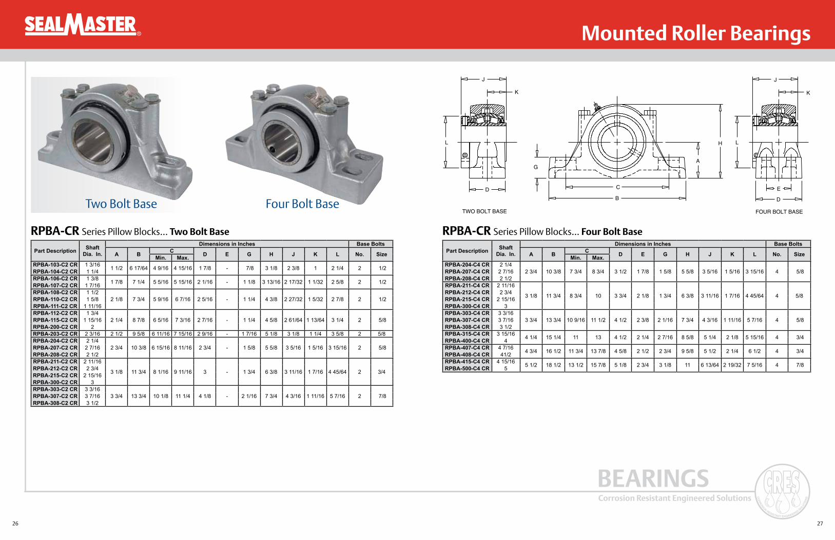
RPBA-CR Series Pillow Blocks... Four Bolt Base
J
K
L
D
G
C
B
A
H L
E
D
J
K
FOUR BOLT BASETWO BOLT BASE
RPBA-CR Series Pillow Blocks... Two Bolt Base
Two Bolt Base Four Bolt Base
Part Description Shaft Dia. In.
Dimensions in Inches Base Bolts
A B C D E G H J K L No. SizeMin. Max.RPBA-103-C2 CR 1 3/16 1 1/2 6 17/64 4 9/16 4 15/16 1 7/8 - 7/8 3 1/8 2 3/8 1 2 1/4 2 1/2RPBA-104-C2 CR 1 1/4RPBA-106-C2 CR 1 3/8 1 7/8 7 1/4 5 5/16 5 15/16 2 1/16 - 1 1/8 3 13/16 2 17/32 1 1/32 2 5/8 2 1/2RPBA-107-C2 CR 1 7/16RPBA-108-C2 CR 1 1/2
2 1/8 7 3/4 5 9/16 6 7/16 2 5/16 - 1 1/4 4 3/8 2 27/32 1 5/32 2 7/8 2 1/2RPBA-110-C2 CR 1 5/8RPBA-111-C2 CR 1 11/16RPBA-112-C2 CR 1 3/4
2 1/4 8 7/8 6 5/16 7 3/16 2 7/16 - 1 1/4 4 5/8 2 61/64 1 13/64 3 1/4 2 5/8RPBA-115-C2 CR 1 15/16RPBA-200-C2 CR 2RPBA-203-C2 CR 2 3/16 2 1/2 9 5/8 6 11/16 7 15/16 2 9/16 - 1 7/16 5 1/8 3 1/8 1 1/4 3 5/8 2 5/8RPBA-204-C2 CR 2 1/4
2 3/4 10 3/8 6 15/16 8 11/16 2 3/4 - 1 5/8 5 5/8 3 5/16 1 5/16 3 15/16 2 5/8RPBA-207-C2 CR 2 7/16RPBA-208-C2 CR 2 1/2RPBA-211-C2 CR 2 11/16
3 1/8 11 3/4 8 1/16 9 11/16 3 - 1 3/4 6 3/8 3 11/16 1 7/16 4 45/64 2 3/4RPBA-212-C2 CR 2 3/4RPBA-215-C2 CR 2 15/16RPBA-300-C2 CR 3RPBA-303-C2 CR 3 3/16
3 3/4 13 3/4 10 1/8 11 1/4 4 1/8 - 2 1/16 7 3/4 4 3/16 1 11/16 5 7/16 2 7/8RPBA-307-C2 CR 3 7/16RPBA-308-C2 CR 3 1/2
Part Description Shaft Dia. In.
Dimensions in Inches Base Bolts
A B C D E G H J K L No. SizeMin. Max.RPBA-204-C4 CR 2 1/4
2 3/4 10 3/8 7 3/4 8 3/4 3 1/2 1 7/8 1 5/8 5 5/8 3 5/16 1 5/16 3 15/16 4 5/8RPBA-207-C4 CR 2 7/16RPBA-208-C4 CR 2 1/2RPBA-211-C4 CR 2 11/16
3 1/8 11 3/4 8 3/4 10 3 3/4 2 1/8 1 3/4 6 3/8 3 11/16 1 7/16 4 45/64 4 5/8RPBA-212-C4 CR 2 3/4RPBA-215-C4 CR 2 15/16RPBA-300-C4 CR 3RPBA-303-C4 CR 3 3/16
3 3/4 13 3/4 10 9/16 11 1/2 4 1/2 2 3/8 2 1/16 7 3/4 4 3/16 1 11/16 5 7/16 4 5/8RPBA-307-C4 CR 3 7/16RPBA-308-C4 CR 3 1/2RPBA-315-C4 CR 3 15/16 4 1/4 15 1/4 11 13 4 1/2 2 1/4 2 7/16 8 5/8 5 1/4 2 1/8 5 15/16 4 3/4RPBA-400-C4 CR 4RPBA-407-C4 CR 4 7/16 4 3/4 16 1/2 11 3/4 13 7/8 4 5/8 2 1/2 2 3/4 9 5/8 5 1/2 2 1/4 6 1/2 4 3/4RPBA-408-C4 CR 41/2RPBA-415-C4 CR 4 15/16 5 1/2 18 1/2 13 1/2 15 7/8 5 1/8 2 3/4 3 1/8 11 6 13/64 2 19/32 7 5/16 4 7/8RPBA-500-C4 CR 5

28 29
Corrosion Resistant Engineered Solutions
BEARINGS
®
RFBA-CR Series Flange Units
Mounted Roller Bearings
B SQ.
D SQ.
DD BOLT CIRCLE DIA.
F
A
C
H
E
JL
RFB RFBA
A
C
H
EE
RFB-CR Series Flange UnitsPart
DescriptionShaft
Dia. In.Dimensions in Inches
A B C D DD E F BOLT H J LRFB-103-C CR 1 3/16 2 13/16 4 2 5/16 2 7/8 4 1/16 1/16 3/8 1 3 1/4 2 1/4RFB-104-C CR 1 1/4RFB-106-C CR 1 3/8 3 1/16 4 5/8 2 9/16 3 1/2 4 15/16 1/16 1/2 1 3 3/4 2 5/8RFB-107-C CR 1 7/16RFB-108-C CR 1 1/2
3 1/2 5 3/8 2 15/16 4 1/8 5 13/16 1/8 1/2 1 3/16 4 1/2 2 7/8RFB-110-C CR 1 5/8RFB-111-C CR 1 11/16RFB-112-C CR 1 3/4
3 5/8 5 5/8 3 1/16 4 3/8 6 3/16 1/8 1/2 1 3/16 4 3/4 3 1/4RFB-115-C CR 1 15/16RFB-200-C CR 2RFB-203-C CR 2 3/16 3 7/8 6 1/4 3 1/4 4 7/8 6 29/32 1/8 5/8 1 3/8 5 1/4 3 5/8RFB-204-C CR 2 1/4
4 3/16 6 7/8 3 9/16 5 3/8 7 39/64 3/16 5/8 1 1/2 5 3/4 3 15/16RFB-207-C CR 2 7/16RFB-208-C CR 2 1/2RFB-211-C CR 2 11/16
4 11/16 7 3/4 3 15/16 6 8 31/64 3/16 3/4 1 5/8 6 1/2 4 23/32RFB-212-C CR 2 3/4RFB-215-C CR 2 15/16RFB-300-C CR 3RFB-303-C CR 3 3/16
5 1/4 9 1/4 4 1/2 7 9 29/32 15/64 3/4 1 7/8 8 5 7/16RFB-307-C CR 3 7/16RFB-308-C CR 3 1/2RFB-315-C CR 3 15/16 6 1/2 10 1/4 5 5/8 7 3/4 10 61/64 1/4 7/8 2 1/8 8 7/8 5 15/16RFB-400-C CR 4
Part Description
Shaft Dia. In.
Dimensions in InchesA B C D DD EE F BOLT H J L
RFBA-103-C CR 1 3/16 2 13/16 4 2 5/16 2 7/8 4 1/16 7/16 3/8 1 3 1/4 2 1/4RFBA-104-C CR 1 1/4RFBA-106-C CR 1 3/8 3 1/16 4 5/8 2 9/16 3 1/2 4 15/16 17/32 1/2 1 3 3/4 2 5/8RFBA-107-C CR 1 7/16RFBA-108-C CR 1 1/2
3 1/2 5 3/8 2 15/16 4 1/8 5 13/16 21/32 1/2 1 3/16 4 1/2 2 7/8RFBA-110-C CR 1 5/8RFBA-111-C CR 1 11/16RFBA-112-C CR 1 3/4
3 5/8 5 5/8 3 1/16 4 3/8 6 3/16 43/64 1/2 1 3/16 4 3/4 3 1/4RFBA-115-C CR 1 15/16RFBA-200-C CR 2RFBA-203-C CR 2 3/16 3 7/8 6 1/4 3 1/4 4 7/8 6 29/32 3/4 5/8 1 3/8 5 1/4 3 5/8RFBA-204-C CR 2 1/4
4 3/16 6 7/8 3 9/16 5 3/8 7 39/64 7/8 5/8 1 1/2 5 3/4 3 15/16RFBA-207-C CR 2 7/16RFBA-208-C CR 2 1/2RFBA-211-C CR 2 11/16
4 11/16 7 3/4 3 15/16 6 8 31/64 1 3/4 1 5/8 6 1/2 4 23/32RFBA-212-C CR 2 3/4RFBA-215-C CR 2 15/16RFBA-300-C CR 3RFBA-303-C CR 3 3/16
5 1/4 9 1/4 4 1/2 7 9 29/32 1 1/16 3/4 1 7/8 8 5 7/16RFBA-307-C CR 3 7/16RFBA-308-C CR 3 1/2RFBA-315-C CR 3 15/16 6 1/2 10 1/4 5 5/8 7 3/4 10 61/64 1 1/4 7/8 2 1/8 8 7/8 5 15/16RFBA-400-C CR 4

30 31
Corrosion Resistant Engineered Solutions
BEARINGS
® Mounted Ball Bearings
In addition to the Sealmaster standard platform features, CR Gold bearings offer a stainless steel housing, black oxide insert, single lip contact seal and H1 food grade grease.
CR Gold Mounted Ball Bearings
CRES Housing: 316 Passivated Stainless SteelBearing Races: Black Oxide 52100 SteelBalls: 52100 SteelRetainer: Unique Metal Land Riding RetainerSeal: Single Lip Rubber Contact SealSet Screws: Black Oxided Steel Diamond Faceted Cup PointGrease Fitting: 303 Stainless SteelGrease: Sealmaster GoldPlex-FG
Components Material
InsertBlack Oxided Races: Marginal improvement to corrosion resistance compared to
52100 steel.
Single Lip Rubber Contact Seal: Contamination avoidance and lubrication retention.
Wide Outer Race Design: Extra grease capacity.
Zone Hardened Inner Race: Improved locking reliability.
Unique Metal Land Riding Retainer: Corrosion resistant, improves lubrication circulation.
Lock Pin and Dimple System: Provides direct lubrication path and +/-2° static misalignment and prevents outer race rotation.
H1 Food Grade Grease: Non-toxic grease with superior corrosion resistance and excellent wash out properties.
Housing316 Passivated Stainless Steel: Highest amount of corrosion resistance currently available
for stainless steel bearing housings.
Advanced Casting Technology: Investment cast process yields a smooth, easy to clean surface.
Solid Construction – Machined Base: Minimal gaps, no fillings, smooth easy to clean surface.
Specialized Laser Identification: Permanent brand and nomenclature marking.
Features and Benefits
Nomenclature:
NP - 16C CR Corrosion Resistant
Contact Seal
Bore Size in 1/16"
Housing Type NP = Pillow Block SFT = 2 Bolt Flange SF = 4 Bolt Flange FB = Flange Bracket

32 33
Corrosion Resistant Engineered Solutions
BEARINGS
® Mounted Ball Bearings
E
M K45°
B
A
J
PD
C
SHOWN WITHOPTIONAL END CAP
J
K
H
AG
E ECB
L
N
D
SHOWN WITHOPTIONAL END CAP
NP-C CR Series Pillow Blocks SFT-C CR Series 2 Bolt FlangeCR Gold
DescriptionShaft Size A B C Max. C. Min. D E G H J K L N Bolt
SizeOpen Cap
Closed Cap
Backside Shield
NP-12C CR 3/4 1 5/16 5 4 1/8 3 3/8 1 1/2 3/4 1/2 2 9/16 1 7/32 23/32 3 9/32 1 41/64 3/8 ECO-12 ECC-12 N/A
NP-16C CR 1 1 7/16 5 1/2 4 1/2 3 3/4 1 1/2 3/4 1/2 2 13/16 1 3/8 13/16 3 15/32 1 47/64 3/8 ECO-16 ECC-16 N/A
NP-19C CR 1 3/16 1 11/16 6 1/2 5 1/16 4 7/16 1 7/8 13/16 9/16 3 3/8 1 1/2 7/8 3 19/32 1 51/64 1/2 ECO-19 ECC-19 N/A
NP-20RC CR 1 1/4 1 11/16 6 1/2 5 1/16' 4 7/16 1 7/8 13/16 9/16 3 3/8 1 1/2 7/8 3 19/32 1 51/64 1/2 ECO-20R ECC-19 N/A
NP-20C CR 1 1/4 1 7/8 6 9/16 5 5/16 4 11/16 1 7/8 13/16 5/8 3 3/4 1 11/16 1 3 27/32 1 59/64 1/2 ECO-20 ECC-23 N/A
NP-23C CR 1 7/16 1 7/8 6 9/16 5 5/16 4 11/16 1 7/8 13/16 5/8 3 3/4 1 11/16 1 3 27/32 1 59/64 1/2 ECO-23 ECC-23 N/A
NP-24C CR 1 1/2 1 15/16 7 1/4 5 7/8 4 7/8 2 1/8 1 11/16 3 15/16 1 15/16 1 3/16 4 7/32 2 7/64 1/2 ECO-24 ECC-24 N/A
NP-27C CR 1 11/16 2 1/8 7 1/2 6 1/16 5 7/16 2 1/8 13/16 11/16 4 1/4 1 15/16 1 3/16 4 7/32 2 1/8 1/2 ECO-27 ECC-27 N/A
NP-31C CR 1 15/16 2 1/4 8 1/8 6 1/2 6 2 3/8 7/8 3/4 4 9/16 2 1/32 1 9/32 4 13/32 2 13/64 5/8 ECO-31 ECC-31 N/A
NP-32C CR 2 2 1/2 8 5/8 7 6 1/2 2 3/8 7/8 3/4 5 2 3/16 1 5/16 4 43/64 2 21/64 5/8 ECO-32 ECC-235 N/A
NP-35C CR 2 3/16 2 1/2 8 5/8 7 6 1/2 2 3/8 7/8 3/4 5 2 3/16 1 5/16 4 43/64 2 21/64 5/8 ECO-35 ECC-35 N/A
NP-39C CR 2 7/16 2 3/4 9 1/2 7 5/8 6 7/8 2 3/4 1 7/8 5 9/16 2 9/16 1 9/16 5 11/64 2 37/64 5/8 ECO-39 ECC-239 N/A
CR Gold Description Shaft Size A B C D E J K M P Bolt Size Open Cap Closed
CapBackside
Shield
SFT-12C CR 3/4 4 13/32 3 17/32 7/16 31/32 1 9/32 2 1/2 1/2 23/32 2 13/64 3/8 ECO-12 ECC-12 2BSS-12
SFT-16C CR 1 4 7/8 3 57/64 17/32 1 5/64 1 7/16 2 3/4 9/16 13/16 2 23/64 7/16 ECO-16 ECC-16 2BSS-16
SFT-19C CR 1 3/16 5 9/16 4 19/32 17/32 1 7/32 1 9/16 3 1/4 5/8 7/8 2 31/64 7/16 ECO-19 ECC-19 2BSS-19
SFT-20RC CR 1 1/4 5 9/16 4 19/32 17/32 1 7/32 1 9/16 3 1/4 5/8 7/8 2 31/64 7/16 ECO-20R ECC-19 2BSS-20R
SFT-20C CR 1 1/4 6 1/8 5 1/8 9/16 1 11/32 1 3/4 3 3/4 11/16 1 2 43/64 1/2 ECO-20 ECC-23 2BSS-20
SFT-23C CR 1 7/16 6 1/8 5 1/8 9/16 1 11/32 1 3/4 3 3/4 11/16 1 2 43/64 1/2 ECO-23 ECC-23 2BSS-23
SFT-24C CR 1 1/2 6 3/4 5 21/32 9/16 1 1/2 2 1/64 4 1/8 3/4 1 3/16 2 15/16 1/2 ECO-24 ECC-24 2BSS-24
SFT-27C CR 1 11/16 7 1/16 5 27/32 9/16 1 9/16 2 3/64 4 3/8 3/4 1 3/16 2 31/32 9/16 ECO-27 EC-27 2BSS-27
SFT-31C CR 1 15/16 7 7/16 6 3/16 9/16 1 9/16 2 5/32 4 9/16 3/4 1 9/32 3 5/64 9/16 ECO-31 ECC-31 2BSS-31
SFT-32C CR 2 8 1/2 7 1/4 13/16 1 3/4 2 5/16 5 1/4 7/8 1 5/16 3 21/64 5/8 ECO-32 ECC-35 N/A
SFT-35C CR 2 3/16 8 1/2 7 1/4 13/16 1 3/4 2 5/16 5 1/4 7/8 1 5/16 3 21/64 5/8 ECO-35 ECC-35 2BSS-35

34 35
Corrosion Resistant Engineered Solutions
BEARINGS
® Mounted Ball Bearings
FB-C CR Series Flange Bracket SF-C CR Series 4 Bolt Flange
EM N
I
45°
H
A
D
F
C
B
O
J
G
SHOWN WITHOPTIONAL END CAP
EM K
B SQ.
A SQ.
C
PD
J
SHOWN WITHOPTIONAL END CAP
CR Gold Description
Shaft Size A B C D E F G H I J M N O Bolt
SizeOpen Cap
Closed Cap
Backside Shield
FB-12C CR 3/4 3 2 3/8 1 1/2 1 11/16 1 11/32 7/8 5/16 4 1/4 2 1/2 1 1/32 23/32 1/2 2 17/64 3/8 ECO-12 ECC-12 N/A
FB-16C CR 1 3 3/8 2 1/2 1 5/8 1 13/16 1 1/2 1 1/8 3/8 4 3/4 2 3/4 1 9/64 13/16 9/16 2 13/32 3/8 ECO-16 ECC-16 N/A
FB-19C CR 1 3/16 3 3/4 2 3/4 1 7/8 2 1/16 1 5/8 1 1/4 3/8 5 3/8 3 1/4 1 9/32 7/8 5/8 2 35/64 3/8 ECO-19 ECC-19 N/A
FB-20RC CR 1 1/4 3 3/4 2 3/4 1 7/8 2 1/16 1 5/8 1 1/4 3/8 5 3/8 3 1/4 1 9/32 7/8 5/8 2 35/64 3/8 ECO-20R ECC-19 N/A
FB-20C CR 1 1/4 4 1/4 3 1/4 2 2 3/8 1 7/8 1 1/4 1/2 6 1/8 3 3/4 1 15/32 1 11/16 2 51/64 1/2 ECO-20 ECC-23 N/A
FB-23C CR 1 7/16 4 1/4 3 1/4 2 2 3/8 1 7/8 1 1/4 1/2 6 1/8 3 3/4 1 15/32 1 11/16 2 51/64 1/2 ECO-23 ECC-23 N/A
CR Gold Description
Shaft Size A B C D E J K M P Bolt
SizeOpen Cap
Closed Cap
Backside Shield
SF-12C CR 3/4 3 3/8 2 1/2 7/16 31/32 1 9/32 2 1/2 1/2 23/32 2 13/64 3/8 ECO-12 ECC-12 4BSS-12
SF-16C CR 1 3 3/4 2 3/4 17/32 1 5/64 1 7/16 2 45/64 9/16 13/16 2 23/64 7/16 ECO-16 ECC-16 4BSS-16
SF-19C CR 1 3/16 4 1/4 3 1/4 17/32 1 7/32 1 9/16 3 13/64 5/8 7/8 2 31/64 7/16 ECO-19 ECC-19 4BSS-19
SF-20RC CR 1 1/4 4 1/4 3 1/4 17/32 1 7/32 1 9/16 3 13/64 5/8 7/8 2 31/64 7/16 ECO-20R ECC-19 4BSS-20R
SF-20C CR 1 1/4 4 5/8 3 5/8 9/16 1 11/32 1 3/4 3 3/4 11/16 1 2 43/64 1/2 ECO-20 ECC-23 4BSS-20
SF-23C CR 1 7/16 4 5/8 3 5/8 9/16 1 11/32 1 3/4 3 3/4 11/16 1 2 43/64 1/2 ECO-23 ECC-23 4BSS-23
SF-24C CR 1 1/2 5 1/8 4 9/16 1 1/2 2 1/64 4 5/64 3/4 1 3/16 2 15/16 1/2 ECO-24 ECC-24 4BSS-24
SF-27C CR 1 11/16 5 3/8 4 1/8 9/16 1 9/16 2 3/64 4 21/64 3/4 1 3/16 2 31/32 9/16 ECO-27 ECC-27 4BSS-27
SF-31C CR 1 5/16 5 5/8 4 3/8 9/16 1 9/16 2 5/32 4 35/64 3/4 1 9/32 3 5/64 9/16 ECO-31 ECC-31 4BSS-31
SF-32C CR 2 6 3/8 5 1/8 13/16 1 3/4 2 5/16 5 3/16 7/8 1 5/16 3 21/64 5/8 ECO-32 ECC-35 4BSS-32
SF-35C CR 2 3/16 6 3/8 5 1/8 13/16 1 3/4 2 5/16 5 3/16 7/8 1 5/16 3 21/64 5/8 ECO-35 ECC-35 4BSS-35
SF-39C CR 2 7/16 6 7/8 5 5/8 13/16 1 15/16 2 25/32 5 7/16 1 1 9/16 3 45/64 5/8 ECO-39 ECC-39 4BSS-39

36 37
Corrosion Resistant Engineered Solutions
BEARINGS
®
PN Gold bearings feature a high phosphorus, electroless nickel coated steel insert and a patented, multiple lip high performance seal. Specially engineered for industries with corrosive wash down environments such as food and beverage, pharmaceuticals and chemical processing. The PN Gold mounted ball bearings provide outstanding performance in demanding corrosive environments.
PN Gold Mounted Ball Bearings
CRES
Housing: 316 Passivated Stainless Steel or High Strength Composite
Bearing Races: High Phosphorus Electroless Nickel Plated 52100 Steel
Balls: 440C Stainless SteelRetainer: Unique Metal Land Riding RetainerSeal: High Performance Seal (HPS)Set Screws: 300 Stainless SteelGrease Fitting: 303 Stainless SteelGrease: Sealmaster GoldPlex-FG
Components Material
InsertHigh Phosphorus Electroless Nickel Plating: Provides exceptional corrosion resistance.
High Performance Seal (HPS): Multi-directional sealing with excellent chemical resistance.
Wide Outer Race: Provides extra grease capacity.
Zone Hardened Inner Race: Provides longer life and quieter operation, improved locking reliability.
Unique Metal Land Riding Retainer: Corrosion resistant, improves lubrication circulation.
Lock Pin and Dimple System: Provides direct lubrication path and +/- 2° static misalignment and prevents outer race rotation.
H1 Food Grade Grease: Non-toxic grease with superior corrosion resistance and excellent wash out properties.
Features and Benefits
Mounted Ball Bearings
Nomenclature:
BCRPS - PN16T RM Reduced Maintenance Suffix T = SKWEZLOC®
S = Plugged, No Lube Fitting
Bore Size = 1/16"
Phosphorus Nickel
Housing Material S = Stainless Steel C = Composite F = Flouropolymer Coated*
Housing Type P = Pillow Block FT = 2 Bolt Flange F = 4 Bolt Flange FB = Flange Bracket TB = Tapped Base
Corrosion Resistant
Machine for Bolt on End Cap*** Not available on all products. Please see page 23 for more information on flouropolymer coating. ** Not available on all products, includes backside shield.

38 39
Corrosion Resistant Engineered Solutions
BEARINGS
®
Features and Benefits
Mounted Ball Bearings
304 Stainless steel seal cage
304 Stainless steel flinger
Grease cavity
Axial lip
Radial lip
Grease cavity
Grease cavity
Sealmaster Patented HPS Seal for Superior Protection • Triple lip contact seal design
provides multi-directional sealing to minimize contamination ingress and retain lubrication
• Highly durable, FKM seal lip material provides good chemical resistance and can withstand high temperatures
• 304 stainless steel shell protects bearing components from incoming contaminants
• 304 stainless steel rotating flinger provides a corrosion resistant wear surface for all three lips and shields seal from contamination and washdown
• Grease cavities in seal assembly are factory filled with lubricant prior to shipment for additional contaminant avoidance
Sealmaster HPS Seal(U.S. Patent Number 6,817,769)
Stainless Steel Housing
Composite Housing
Stainless Steel Housing316 Passivated Stainless Steel: Highest amount of corrosion resistance currently available
for stainless steel bearing housings.
Advanced Casting Technology: Investment cast process yields a smooth, easy to clean surface.
Solid Construction – Machined Base: Minimal gaps, no fillings, smooth easy to clean surface.
Specialized Laser Identification: Permanent brand and nomenclature marking.
Composite HousingHigh Strength Composite: High load capacity.
Solid Construction – Machined Base: Minimal gaps, no filling, smooth easy to clean surface.
Reinforced Stainless Steel Bolt Ferrules: Increased strength around bolt holes.
Specialized Unit Identification: Permanent brand and nomenclature marking.

40 41
Corrosion Resistant Engineered Solutions
BEARINGS
® Mounted Ball Bearings
The key to overall locking performance. The patented SKWEZLOC locking collar puts it a world apart from ordinary shaft locking devices. Six equally-spaced centering surfaces (inner race fingers or extension tabs) grip the shaft and hold it tight, locating it in near-perfect concentricity with the race. Fretting corrosion is reduced. Balancing of the assembly is easier and locking reliability is maintained.
PN Gold with SKWEZLOC Shaft Locking Mechanism
CRES SKWEZLOC Locking Collar Centers the Shaft in the Bearing Bore... Secures the Shaft with Near–Perfect Concentricity
• Quieter smoother operation at higher speeds
• Quickly, easily installed, removed and/or repositioned
• Shaft protected from scoring or burring
• Reduced out-of-balance virbrational forces and fretting corrosion
“Putting the Collar” on Vibration...The design of the unique SKWEZLOC collar and the near–perfect shaft centering greatly reduces out-of-balance vibrational forces that tend to shorten bearing life. Fretting corrosion is also minimized.
“Rings True” – Every Time...Because the SKWEZLOC collar centers the shaft concentricity in the bore of the bearing, the shaft runs truer and you save on bearing maintenance and replacement costs. Because there is no set screw, shaft marring is avoided. Ballpath roundness is maintained.

42 43
Corrosion Resistant Engineered Solutions
BEARINGS
® Mounted Ball Bearings
J J
.06” K K
SKWEZLOCLOCKING
SET SCREWLOCKING
H
A
G
E E
CB
L
N
D
SHOWN WITHOPTIONAL END CAP
CRPS-PN, CRPS-PN T Series Pillow Blocks / Stainless Steel Housings CRPS-PN, CRPS-PN T Series Pillow Blocks / Stainless Steel HousingsSetscrew
DescriptionSKWEZLOC Description Shaft Size A B C Max. C Min. D E G
CRPS-PN12 CRPS-PN12T 3/4 1 5/16 5 4 1/8 3 3/8 1 1/2 3/4 1/2CRPS-PN16 CRPS-PN16T 1 1 7/16 5 1/2 4 1/2 3 3/4 1 1/2 3/4 1/2CRPS-PN19 CRPS-PN19T 1 3/16 1 11/16 6 1/2 5 1/16 4 7/16 1 7/8 13/16 9/16CRPS-PN20R CRPS-PN20RT 1 1/4 1 11/16 6 1/2 5 1/16 4 7/16 1 7/8 13/16 9/16CRPS-PN20 CRPS-PN20T 1 1/4 1 7/8 6 9/16 5 5/16 4 11/16 1 7/8 13/16 5/8CRPS-PN23 CRPS-PN23T 1 7/16 1 7/8 6 9/16 5 5/16 4 11/16 1 7/8 13/16 5/8CRPS-PN24 CRPS-PN24T 1 1/2 1 15/16 7 1/4 5 7/8 4 7/8 2 1/8 1 11/16CRPS-PN27 CRPS-PN27T 1 11/16 2 1/8 7 1/2 6 1/16 5 7/16 2 1/8 13/16 11/16CRPS-PN31 CRPS-PN31T 1 15/16 2 1/4 8 1/8 6 1/2 6 2 3/8 7/8 3/4CRPS-PN32 CRPS-PN32T 2 2 1/2 8 5/8 7 6 1/2 2 3/8 7/8 3/4CRPS-PN35 CRPS-PN35T 2 3/16 2 1/2 8 5/8 7 6 1/2 2 3/8 7/8 3/4CRPS-PN39 CRPS-PN39T 2 7/16 2 3/4 9 1/2 7 5/8 6 7/8 2 3/4 1 7/8
H J K L N Bolt Size Open Cap Closed Cap Backside Shield
Setscrew Description
SKWEZLOC Description
2 9/16 1 7/32 23/32 3 9/32 1 41/64 3/8 ECO-12 ECC-12 N/A CRPS-PN12 CRPS-PN12T2 3/16 1 3/8 13/16 3 15/32 1 47/64 3/8 ECO-16 ECC-16 N/A CRPS-PN16 CRPS-PN16T3 3/8 1 1/2 7/8 3 19/32 1 51/64 1/2 ECO-19 ECC-19 N/A CRPS-PN19 CRPS-PN19T3 3/8 1 1/2 7/8 3 19/32 1 51/64 1/2 ECO-20R ECC-19 N/A CRPS-PN20R CRPS-PN20RT3 3/4 1 11/16 1 3 27/32 1 59/64 1/2 ECO-20 ECC-23 N/A CRPS-PN20 CRPS-PN20T3 3/4 1 11/16 1 3 27/32 1 59/64 1/2 ECO-23 ECC-23 N/A CRPS-PN23 CRPS-PN23T
3 15/16 1 15/16 1 3/16 4 7/32 2 7/64 1/2 ECO-24 ECC-24 N/A CRPS-PN24 CRPS-PN24T4 1/4 1 15/16 1 3/16 4 7/32 2 1/8 1/2 ECO-27 ECC-27 N/A CRPS-PN27 CRPS-PN27T
4 9/16 2 1/32 1 9/32 4 13/32 2 13/64 5/8 ECO-31 ECC-31 N/A CRPS-PN31 CRPS-PN31T5 2 3/16 1 5/16 4 43/64 2 21/64 5/8 ECO-32 ECC-35 N/A CRPS-PN32 CRPS-PN32T5 2 3/16 1 5/16 4 43/64 2 21/64 5/8 ECO-35 ECC-35 N/A CRPS-PN35 CRPS-PN35T
5 9/16 2 9/16 1 9/16 5 11/64 2 37/64 5/8 ECO-39 ECC-39 N/A CRPS-PN39 CRPS-PN39T

44 45
Corrosion Resistant Engineered Solutions
BEARINGS
® Mounted Ball Bearings
CRFTS-PN, CRFTS-PN T Series 2 Bolt Flange / Stainless Steel Housings CRFTS-PN, CRFTS-PN T Series 2 Bolt Flange / Stainless Steel Housings
E E
M MK K.06”
45°
SKWEZLOCLOCKING
SET SCREWLOCKING
J
B
A
P
D
C
SHOWN WITHOPTIONAL END CAP
Setscrew Description
SKWEZLOC Description Shaft Size A B C D E J
CRFTS-PN12 CRFTS-PN12T 3/4 4 13/32 3 17/32 71/6 31/32 1 9/32 2 1/2CRFTS-PN16 CRFTS-PN16T 1 4 7/8 3 57/64 17/32 1 5/64 1 7/16 2 3/4CRFTS-PN19 CRFTS-PN19T 1 3/16 5 9/16 4 19/32 17/32 1 7/32 1 9/16 3 1/4CRFTS-PN20R CRFTS-PN20RT 1 1/4 5 9/16 4 19/32 17/32 1 7/32 1 9/16 3 1/4CRFTS-PN20 CRFTS-PN20T 1 1/4 6 1/8 5 1/8 9/16 1 11/32 1 3/4 3 3/4CRFTS-PN23 CRFTS-PN23T 1 7/16 6 1/8 5 1/8 9/16 1 11/32 1 3/4 3 3/4CRFTS-PN24 CRFTS-PN24T 1 1/2 6 3/4 5 21/32 9/16 1 1/2 2 1/64 4 1/8CRFTS-PN27 CRFTS-PN27T 1 11/16 7 1/16 5 27/32 9/16 1 9/16 2 3/64 4 3/8CRFTS-PN31 CRFTS-PN31T 1 15/16 7 7/16 6 3/16 9/16 1 9/16 2 5/32 4 9/16CRFTS-PN32 CRFTS-PN32T 2 8 1/2 7 1/4 13/16 1 3/4 2 5/16 5 1/4CRFTS-PN35 CRFTS-PN35T 2 3/16 8 1/2 7 1/4 13/16 1 3/4 2 5/16 5 1/4
K M P Bolt Size Open End Cap Closed Cap Backside Shield Setscrew Description
SKWEZLOC Description
1/2 23/32 2 13/64 3/8 ECO-12 ECC-12 2BSS-12 CRFTS-PN12 CRFTS-PN12T9/16 13/16 2 23/64 7/16 ECO-16 ECC-16 2BSS-16 CRFTS-PN16 CRFTS-PN16T5/8 7/8 2 31/64 7/16 ECO-19 ECC-19 2BSS-19 CRFTS-PN19 CRFTS-PN19T5/8 7/8 2 31/64 7/16 ECO-20R ECC-19 2BSS-20R CRFTS-PN20R CRFTS-PN20RT
11/16 1 2 43/64 1/2 ECO-20 ECC-23 2BSS-20 CRFTS-PN20 CRFTS-PN20T11/16 1 2 43/64 1/2 ECO-23 ECC-23 2BSS-23 CRFTS-PN23 CRFTS-PN23T3/4 1 3/16 2 15/16 1/2 ECO-24 ECC-24 2BSS-24 CRFTS-PN24 CRFTS-PN24T3/4 1 3/16 2 31/32 9/16 ECO-27 ECC-27 2BSS-27 CRFTS-PN27 CRFTS-PN27T3/4 1 9/32 3 5/64 9/16 ECO-31 ECC-31 2BSS-31 CRFTS-PN31 CRFTS-PN31T7/8 1 5/16 3 21/64 5/8 ECO-32 ECC-35 N/A CRFTS-PN32 CRFTS-PN32T7/8 1 5/16 3 21/64 5/8 ECO-35 ECC-35 2BSS-35 CRFTS-PN35 CRFTS-PN35T
46 47
Corrosion Resistant Engineered Solutions
BEARINGS
® Mounted Ball Bearings
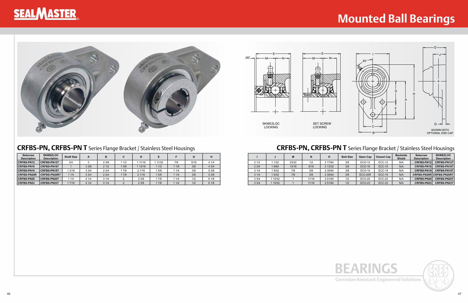
CRFBS-PN, CRFBS-PN T Series Flange Bracket / Stainless Steel Housings CRFBS-PN, CRFBS-PN T Series Flange Bracket / Stainless Steel Housings
E.06” M N
SKWEZLOCLOCKING
SET SCREWLOCKING
E
M NI
45°
C
B
F
D
A
H
O
J
G
SHOWN WITHOPTIONAL END CAP
Setscrew Description
SKWEZLOC Description Shaft Size A B C D E F G H
CRFBS-PN12 CRFBS-PN12T 3/4 3 2 3/8 1 1/2 1 11/16 1 11/32 7/8 5/16 4 1/4CRFBS-PN16 CRFBS-PN16T 1 3 3/8 2 1/2 1 5/8 1 13/16 1 1/2 1 1/8 3/8 4 3/4CRFBS-PN19 CRFBS-PN19T 1 3/16 3 3/4 2 3/4 1 7/8 2 1/16 1 5/8 1 1/4 3/8 5 3/8CRFBS-PN20R CRFBS-PN20RT 1 1/4 3 3/4 2 3/4 1 7/8 2 1/16 1 5/8 1 1/4 3/8 5 3/8CRFBS-PN20 CRFBS-PN20T 1 1/4 4 1/4 3 1/4 2 2 3/8 1 7/8 1 1/4 1/2 6 1/8CRFBS-PN23 CRFBS-PN23T 1 7/16 4 1/4 3 1/4 2 2 3/8 1 7/8 1 1/4 1/2 6 1/8
I J M N O Bolt Size Open Cap Closed Cap Backside Shield
Setscrew Description
SKWEZLOC Description
2 1/2 1 1/32 23/32 1/2 2 17/64 3/8 ECO-12 ECC-12 N/A CRFBS-PN12 CRFBS-PN12T2 3/4 1 9/64 13/16 9/16 2 13/32 3/8 ECO-16 ECC-16 N/A CRFBS-PN16 CRFBS-PN16T3 1/4 1 9/32 7/8 5/8 2 35/64 3/8 ECO-19 ECC-19 N/A CRFBS-PN19 CRFBS-PN19T3 1/4 1 9/32 7/8 5/8 2 35/64 3/8 ECO-20R ECC-19 N/A CRFBS-PN20R CRFBS-PN20RT3 3/4 1 15/32 1 11/16 2 51/64 1/2 ECO-20 ECC-23 N/A CRFBS-PN20 CRFBS-PN20T3 3/4 1 15/32 1 11/16 2 51/64 1/2 ECO-23 ECC-23 N/A CRFBS-PN23 CRFBS-PN23T

48 49
Corrosion Resistant Engineered Solutions
BEARINGS
® Mounted Ball Bearings
CRFS-PN, CRFS-PN T Series 4 Bolt Flange Bracket / Stainless Steel Housings CRFS-PN, CRFS-PN T Series 4 Bolt Flange Bracket / Stainless Steel Housings
E.06 M K
EM K
SKWEZLOCLOCKING
SET SCREWLOCKING B SQ.
A SQ.
P
J
D
C
SHOWN WITHOPTIONAL END CAP
Setscrew Description
SKWEZLOC Description Shaft Size A B C D E J
CRFS-PN12 CRFS-PN12T 3/4 3 3/8 2 1/2 7/16 31/32 1 9/32 2 1/2CRFS-PN16 CRFS-PN16T 1 3 3/4 2 3/4 17/32 1 5/64 1 7/16 2 45/64CRFS-PN19 CRFS-PN19T 1 3/16 4 1/4 3 1/4 17/32 1 7/32 1 9/16 3 13/64CRFS-PN20R CRFS-PN20R 1 1/4 4 1/4 3 1/4 17/32 1 7/32 1 9/16 3 13/64CRFS-PN20 CRFS-PN20T 1 1/4 4 5/8 3 5/8 9/16 1 11/32 1 3/4 3 3/4CRFS-PN23 CRFS-PN23T 1 7/16 4 5/8 3 5/8 9/16 1 11/32 1 3/4 3 3/4CRFS-PN24 CRFS-PN24T 1 1/2 5 1/8 4 9/16 1 1/2 2 1/64 4 5/64CRFS-PN27 CRFS-PN27T 1 11/16 5 3/8 4 1/8 9/16 1 9/16 2 3/64 4 21/64CRFS-PN31 CRFS-PN31T 1 15/16 5 5/8 4 3/8 9/16 1 9/16 2 5/32 4 35/64CRFS-PN32 CRFS-PN32T 2 6 3/8 5 1/8 13/16 1 3/4 2 5/16 5 3/16CRFS-PN35 CRFS-PN35T 2 3/16 6 3/8 5 1/8 13/16 1 3/4 2 5/16 5 3/16CRFS-PN39 CRFS-PN39T 2 7/16 6 7/8 5 5/8 13/16 1 15/16 2 25/32 5 7/16
K M P Bolt Size Open Cap Closed Cap Backside Shield Setscrew De-scription
SKWEZLOC Description
1/2 23/32 2 13/64 3/8 ECO-12 ECC-12 4BSS-12 CRFS-PN12 CRFS-PN12T9/16 13/16 2 23/64 7/16 ECO-16 ECC-16 4BSS-16 CRFS-PN16 CRFS-PN16T5/8 7/8 2 31/64 7/16 ECO-19 ECC-19 4BSS-19 CRFS-PN19 CRFS-PN19T5/8 7/8 2 31/64 7/16 ECO-20R ECC-19 4BSS-20R CRFS-PN20R CRFS-PN20RT
11/16 1 2 43/64 1/2 ECO-20 ECC-23 4BSS-20 CRFS-PN20 CRFS-PN20T11/16 1 2 43/64 1/2 ECO-23 ECC-23 4BSS-23 CRFS-PN23 CRFS-PN23T3/4 1 3/16 2 15/16 1/2 ECO-24 ECC-24 4BSS-24 CRFS-PN24 CRFS-PN24T3/4 1 3/16 2 31/32 9/16 ECO-27 ECC-27 4BSS-27 CRFS-PN27 CRFS-PN27T3/4 1 9/32 3 5/64 9/16 ECO-31 ECC-31 4BSS-31 CRFS-PN31 CRFS-PN31T7/8 1 5/16 3 21/64 5/8 ECO-32 ECC-35 4BSS-32 CRFS-PN32 CRFS-PN32T7/8 1 5/16 3 21/64 5/8 ECO-35 ECC-35 4BSS-35 CRFS-PN35 CRFS-PN35T1 1 9/16 3 45/64 5/8 ECO-39 ECC-39 4BSS-39 CRFS-PN39 CRFS-PN39T

50 51
Corrosion Resistant Engineered Solutions
BEARINGS
® Mounted Ball Bearings
CRPC-PN, CRPC-PN T Series Pillow Blocks / Composite Housings CRPC-PN, CRPC-PN T Series Pillow Blocks / Composite Housings
J
.06” K K
J
SKWEZLOCLOCKING
SET SCREWLOCKING
E
C
B
E
G
A
H
DSHOWN WITH
OPTIONAL END CAP
L
N
Setscrew Description
SKWEZLOC Description Shaft Size A B C Max. C Min. D E G H
CRPC-PN12 CRPC-PN12T 3/4 1 5/16 5 4 1/8 3 3/8 1 1/2 3/4 9/16 2 35/64CRPC-PN16 CRPC-PN16T 1 1 7/16 5 1/2 4 1/2 3 3/4 1 1/2 3/4 9/16 2 13/16CRPC-PN19 CRPC-PN19T 1 3/16 1 11/16 6 1/2 5 1/16 4 7/16 1 7/8 13/16 11/16 3 21/64CRPC-PN20R CRPC-PN20RT 1 1/4 1 11/16 6 1/2 5 1/16 4 7/16 1 7/8 13/16 11/16 3 21/64CRPC-PN20 CRPC-PN20T 1 1/4 1 7/8 6 9/16 5 5/16 4 11/16 1 7/8 13/16 11/16 3 3/4CRPC-PN23 CRPC-PN23T 1 7/16 1 7/8 6 9/16 5 5/16 4 11/16 1 7/8 13/16 11/16 3 3/4CRPC-PN24 CRPC-PN24T 1 1/2 1 15/16 7 1/4 5 11/16 5 1/16 2 1/8 13/16 11/16 4 1/64
J K L N Bolt Size Open Cap Closed Cap Backside Shield
Setscrew Description
SKWEZLOC Description
1 7/32 23/32 3 9/32 1 41/64 3/8 ECO-12 ECC-12 N/A CRPC-PN12 CRPC-PN12T1 3/8 13/16 3 15/32 1 47/64 3/8 ECO-16 ECC-16 N/A CRPC-PN16 CRPC-PN16T1 1/2 7/8 3 19/32 1 51/64 1/2 ECO-19 ECC-19 N/A CRPC-PN19 CRPC-PN19T1 1/2 7/8 3 19/32 1 51/64 1/2 ECO-20R ECC-19 N/A CRPC-PN20R CRPC-PN20RT
1 11/16 1 3 27/32 1 59/64 1/2 ECO-20 ECC-23 N/A CRPC-PN20 CRPC-PN20T1 11/16 1 3 27/32 1 59/64 1/2 ECO-23 ECC-23 N/A CRPC-PN23 CRPC-PN23T1 15/16 1 3/16 4 7/32 2 7/64 1/2 ECO-24 ECC-24 N/A CRPC-PN24 CRPC-PN24T

52 53
Corrosion Resistant Engineered Solutions
BEARINGS
® Mounted Ball Bearings
CRFTC-PN, CRFTC-PN T Series 2 Bolt Flange / Composite Housings CRFTC-PN, CRFTC-PN T Series 2 Bolt Flange / Composite Housings
E
.06” M K
E
M K
SKWEZLOCLOCKING
SET SCREWLOCKING
60°
B
A
J
P
D
C
SHOWN WITHOPTIONAL END CAP
Setscrew Description
SKWEZLOC Description Shaft Size A B C D E J
CRFTC-PN12 CRFTC-PN12T 3/4 4 15/32 3 17/32 7/16 31/32 1 9/32 2 7/16CRFTC-PN16 CRFTC-PN16T 1 4 15/16 3 57/64 17/32 1 5/64 1 7/16 2 23/32CRFTC-PN19 CRFTC-PN19T 1 3/16 5 11/16 4 19/32 17/32 1 7/32 1 9/16 3 1/4CRFTC-PN20R CRFTC-PN20RT 1 1/4 5 11/16 4 19/32 17/32 1 7/32 1 9/16 3 1/4CRFTC-PN20 CRFTC-PN20T 1 1/4 6 21/64 5 1/8 9/16 1 11/32 1 3/4 3 45/64CRFTC-PN23 CRFTC-PN23T 1 7/16 6 21/64 5 1/8 9/16 1 11/32 1 3/4 3 45/64CRFTC-PN24 CRFTC-PN24T 1 1/2 6 29/32 5 21/32 9/16 1 1/2 2 1/64 4 7/64
K M P Bolt Size Open Cap Closed Cap Backside Shield Setscrew Description
SKWEZLOC Description
1/2 23/32 2 13/64 3/8 ECO-12 ECC-12 2BSS-12 CRFTC-PN12 CRFTC-PN12T9/16 13/16 2 23/64 7/16 ECO-16 ECC-16 2BSS-16 CRFTC-PN16 CRFTC-PN16T5/8 7/8 2 31/64 7/16 ECO-19 ECC-19 2BSS-19 CRFTC-PN19 CRFTC-PN19T5/8 7/8 2 31/64 7/16 ECO-20R ECC-19 2BSS-20R CRFTC-PN20R CRFTC-PN20RT
11/16 1 2 43/64 1/2 ECO-20 ECC-23 2BSS-20 CRFTC-PN20 CRFTC-PN20T11/16 1 2 43/64 1/2 ECO-23 ECC-23 2BSS-23 CRFTC-PN23 CRFTC-PN23T3/4 1 3/16 2 15/16 1/2 ECO-24 ECC-24 2BSS-24 CRFTC-PN24 CRFTC-PN24T

54 55
Corrosion Resistant Engineered Solutions
BEARINGS
® Mounted Ball Bearings
CRTBC-PN, CRTBC-PN T Series Tapped Base / Composite Housings CRTBC-PN, CRTBC-PN T Series Tapped Base / Composite Housings
J
.06” K
J
K
SKWEZLOCLocking
Set ScrewLocking
B
C
N
A
H
LP
D
SHOWN WITHOPTIONAL CAP
Setscrew Description
SKWEZLOC Description Shaft Size A B C D H J K
CRTBC-PN12 CRTBC-PN12T 3/4 1 5/16 3 1/8 2 1 1/2 2 9/16 1 7/32 23/32CRTBC-PN16 CRTBC-PN16T 1 1 7/16 3 2 1 1/2 2 13/16 1 3/8 13/16CRTBC-PN19 CRTBC-PN19T 1 3/16 1 11/16 4 3 1 1/2 3 3/8 1 1/2 7/8CRTBC-PN20R CRTBC-PN20RT 1 1/4 1 11/16 4 3 1 1/2 3 3/8 1 1/2 7/8CRTBC-PN20 CRTBC-PN20T 1 1/4 1 7/8 4 1/4 3 1/4 1 7/8 3 3/4 1 11/16 1CRTBC-PN23 CRTBC-PN23T 1 7/16 1 7/8 4 1/4 3 1/4 1 7/8 3 3/4 1 11/16 1CRTBC-PN24 CRTBC-PN24T 1 1/2 1 15/16 4 5/8 3 1/2 1 7/8 3 15/16 1 15/16 1 3/16
L N P Bolt Size Open Cap Closed Cap Backside Shield Set Screw Description
SKWEZLOC Description
3 9/32 1/2 1 41/64 3/8-16 ECO-12 ECC-12 N/A CRTBC-PN12 CRTBC-PN12T3 15/32 1/2 1 47/64 3/8-16 ECO-16 ECC-16 N/A CRTBC-PN16 CRTBC-PN16T3 19/32 5/8 1 51/64 7/16-14 ECO-19 ECC-19 N/A CRTBC-PN19 CRTBC-PN19T3 19/32 5/8 1 51/64 7/16-14 ECO-20R ECC-19 N/A CRTBC-PN20R CRTBC-PN20RT3 27/32 3/4 1 59/64 1/2-13 ECO-20 ECC-23 N/A CRTBC-PN20 CRTBC-PN20T3 27/32 3/4 1 59/64 1/2-13 ECO-23 ECC-23 N/A CRTBC-PN23 CRTBC-PN23T4 7/32 3/4 2 7/64 1/2-13 ECO-24 ECC-24 N/A CRTBC-PN24 CRTBC-PN24T

56 57
Corrosion Resistant Engineered Solutions
BEARINGS
® Mounted Ball Bearings
CRFC-PN, CRFC-PN T Series 4 Bolt Flange / Composite Housings CRFC-PN, CRFC-PN T Series 4 Bolt Flange / Composite Housings
E
.06”
M K
E
M K
SKWEZLOCLOCKING
SET SCREWLOCKING B SQ.
A SQ.
P
D
J
C
SHOWN WITHOPTIONAL CAP
Set Screw Description
SKWEZLOC Description Shaft Size A B C D E J
CRFC-PN12 CRFC-PN12T 3/4 3 7/16 2 1/2 7/16 61/64 1 9/32 2 3/8CRFC-PN16 CRFC-PN16T 1 3 51/64 2 3/4 17/32 1 5/64 1 7/16 2 21/32CRFC-PN19 CRFC-PN19T 1 3/16 4 11/32 3 1/4 17/32 1 13/64 1 9/16 3 3/16CRFC-PN20R CRFC-PN20RT 1 1/4 4 11/32 3 1/4 17/32 1 13/64 1 9/16 3 3/16CRFC-PN20 CRFC-PN20T 1 1/4 4 53/64 3 5/8 9/16 1 11/32 1 3/4 3 21/32CRFC-PN23 CRFC-PN23T 1 7/16 4 53/64 3 5/8 9/16 1 11/32 1 3/4 3 21/32CRFC-PN24 CRFC-PN24T 1 1/2 5 1/4 4 9/16 1 1/2 2 1/64 4 1/64
K M P Bolt Size Open Cap Closed Cap Backside Shield Set Screw Description
SKWEZLOC Description
1/2 23/32 2 13/64 3/8 ECO-12 ECC-12 4BSS-12 CRFC-PN12 CRFC-PN12T 9/16 13/16 2 23/64 7/16 ECO-16 ECC-16 4BSS-16 CRFC-PN16 CRFC-PN16T5/8 7/8 2 15/32 7/16 ECO-19 ECC-19 4BSS-19 CRFC-PN19 CRFC-PN19T 5/8 7/8 2 15/32 7/16 ECO-20R ECC-19 4BSS-20R CRFC-PN20R CRFC-PN20RT
11/16 1 2 43/64 1/2 ECO-20 ECC-23 4BSS-20 CRFC-PN20 CRFC-PN20T 11/16 1 2 43/64 1/2 ECO-23 ECC-23 4BSS-23 CRFC-PN23 CRFC-PN23T 3/4 1 3/16 2 15/16 1/2 ECO-24 ECC-24 4BSS-24 CRFC-PN24 CRFC-PN24T

58 59
Corrosion Resistant Engineered Solutions
BEARINGS
®
Mounted Ball Bearings
CRES CZ bearings offer a composite housing, zinc dichromate coated insert, contact seal with zinc dichromate coated flinger and H1 food grade grease.
CZ Mounted Ball Bearings
CRES Housing: High Strength CompositeBearing Races: Zinc Dichromate Coated 52100 SteelBalls: 52100 SteelRetainer: Nylon Ball RidingSeal: Single Lip Rubber Contact SealFlinger: Zinc Dichromate Coated Stainless SteelSet Screws: 300 Series Stainless SteelGrease Fitting: 303 Stainless SteelGrease: H1 Food Grade Grease
Components Material
InsertZinc Dichromate Coated Outer and Inner: Cost effective, reliable performance.
Wide Inner Race: Greater continuous shaft contact.
Honed Ball Paths: Quite operation with less vibration.
Outer Race Anti-Rotation Device: Prevents outer race slippage in housing.
Molded Nitrile Rubber Contact Seal: Contamination resistance and lubrication retention.
Zinc Dichromate Coated Flinger: Additional barrier against contamination and washdown.
H1 Food Grade Grease: Non-toxic grease with superior corrosion resistance and excellent wash out properties.
HousingHigh Strength Composite: High load capacity.
Solid Construction – Machined Base: Minimal gaps, no fillings, smooth easy to clean surface.
Reinforced Stainless Steel Bolt Ferrules: Increased strength around bolt holes.
Specialized Unit Identification: Permanent brand and nomenclature marking.
Features and Benefits
Interchange
The following trade names, trademarks and/or registered trademarks are used in this material by Emerson Power Transmission Corporation for comparison purposes only, are NOT owned by Emerson Power Trans-mission Corporation and are believed to be owned by the following parties: AMI is a registered trademark of ASAHI Tec Corp. of Japan; MRC is a registered trademark of SKF USA Inc. ; Peer is a registered trademark of Peer Bearing Company.
Nomenclature:
CPS - Z 216 Bore Size in 1/16"
200 Series Insert
Zinc Dichromate Coated Insert
Set Screw
Housing Type P = Pillow Block F2 = 2 Bolt Flange F4 = 4 Bolt Flange TB = Tapped Base
Composite Housing Material
Housing Style Browning AMI® MRC® Peer®
Pillow Block CPS-Z200 UCPPL200-MZ2 CPB100-ZM ZUCP200-PBT4 Bolt Flange CF4S-Z200 UCFPL200-MZ2 C4F100-ZM ZUCF200-PBT2 Bolt Flange CF2S-Z200 UCNFL200-MZ2 C2F100-ZM ZUCFT200-PBTTapped Base CTBS-Z200 UCTBL200-MZ2 CTB100-ZM ZUCPA200-PBT

60 61
Corrosion Resistant Engineered Solutions
BEARINGS
®
Mounted Ball Bearings
CPS-Z NGF Series Pillow Blocks / Composite Housings CF2S-Z NGF Series 2 Bolt Flange / Composite Housings
CRES CZ regreaseable options are available by removing the NGF suffix. CRES CZ regreaseable options are available by removing the NGF suffix.
J
K
E EC
B
GA
H
LN
DSHOWN WITH
OPTIONAL END CAP
E
M K
B
A
J
P
D
CSHOWN WITH
OPTIONAL END CAP
CRES CZ Description
Shaft Size A B C
Max.C
Min. D E G H J K L N Bolt Size
Open Cap
Closed Cap
Backside Shield
CPS-Z212 NGF 3/4 1 5/16 5 4 1/8 3 3/8 1 1/2 3/4 9/16 2 35/64 1 7/32 23/32 3 9/32 1 41/64 3/8 ECO-12 ECC-12 N/A
CPS-Z216 NGF 1 1 7/16 5 1/2 4 1/2 3 3/4 1 1/2 3/4 9/16 2 51/64 1 3/8 13/16 3 15/32 1 47/64 3/8 ECO-16 ECC-16 N/A
CPS-Z219-NGF 1 3/16 1 11/16 6 1/2 5 1/16 4 7/16 1 7/8 13/16 11/16 3 21/64 1 1/2 7/8 3 19/32 1 51/64 1/2 ECO-19 ECC-19 N/A
CPS-Z220S NGF 1 1/4 1 11/16 6 1/2 5 1/16 4 7/16 1 7/8 13/16 11/16 3 21/64 1 1/2 7/8 3 19/32 1 51/64 1/2 ECO-20R ECC-19 N/A
CPS-Z220 NGF 1 1/4 1 7/8 6 9/16 5 5/16 4 11/16 1 7/8 13/16 11/16 3 3/4 1 11/16 1 3 27/32 1 59/64 12 ECO-20 ECC-23 N/A
CPS-Z223-NGF 1 7/16 1 7/8 6 9/16 5 5/16 4 11/16 1 7/8 13/16 11/16 3 3/4 1 11/16 1 3 27/32 1 59/64 1/2 ECO-23 ECC-23 N/A
CPS-Z224 NGF 1 1/2 1 15/16 7 1/4 5 11/16 5 1/16 2 1/8 13/16 11/16 4 1/64 1 15/16 1 3/16 4 7/32 2 7/64 1/2 ECO-24 ECC-24 N/A
CRES CZ Description
Shaft Size A B C D E J K M P Bolt
SizeOpen Cap
Closed Cap
Backside Shield
CF2S-Z212 NGF 3/4 4 15/32 3 17/32 7/16 31/32 1 9/32 2 7/16 1/2 23/32 2 13/64 3/8 ECO-12 ECC-12 2BSS-12
CF2S-Z216 NGF 1 4 15/16 3 57/64 17/32 1 5/64 1 7/16 2 23/32 9/16 13/16 2 23/64 7/16 ECO-16 ECC-16 2BSS-16
CF2S-Z219 NGF 1 3/16 5 11/16 4 19/32 17/32 1 7/32 1 9/16 3 1/4 5/8 7/8 2 31/64 7/16 ECO-19 ECC-19 2BSS-19
CF2S-Z220S NGF 1 1/4 5 11/16 4 19/32 17/32 1 7/32 1 9/16 3 1/4 5/8 7/8 2 31/64 7/16 ECO-20R ECC-19 2BSS-20R
CF2S-Z220 NGF 1 1/4 6 21/64 5 1/8 9/16 1 11/32 1 3/4 3 45/64 11/16 1 2 43/64 1/2 ECO-20 ECC-23 2BSS-20
CF2S-Z223 NGF 1 7/16 6 21/64 5 1/8 9/16 1 11/32 1 3/4 3 45/64 11/16 1 2 43/64 1/2 ECO-23 ECC-23 2BSS-23
CF2S-Z224 NGF 1 1/2 6 29/32 5 21/32 9/16 1 1/2 2 1/64 4 7/64 3/4 1 3/16 2 15/16 1/2 ECO-24 ECC-24 2BSS-24

62 63
Corrosion Resistant Engineered Solutions
BEARINGS
®
Mounted Ball Bearings
CTBS-Z NGF Series Tapped Base / Composite Housings CF4S-Z NGF Series 4 Bolt Flange / Composite Housings
CRES CZ regreaseable options are available by removing the NGF suffix. CRES CZ regreaseable options are available by removing the NGF suffix.
J
K
CB
N
A
H
LP
DSHOWN WITH
OPTIONAL END CAP
E
M K
B SQ.
A SQ.
J
PD
CSHOWN WITH
OPTIONAL END CAP
CRES CZ Description
Shaft Size A B C D H J K L N P Bolt
SizeOpenCap
Closed Cap
Backside Shield
CTBS-Z212 NGF 3/4 1 5/16 3 1/8 2 1 1/2 2 9/16 1 7/32 23/32 3 9/32 1/2 1 41/64 3/8-16 ECO-12 ECC-12 N/A
CTBS-Z216 NGF 1 1 7/16 3 2 1 1/2 2 13/16 1 3/8 13/16 3 15/32 1/2 1 47/64 3/8-16 ECO-16 ECC-16 N/A
CTBS-Z219 NGF 1 3/16 1 11/16 4 3 1 1/2 3 3/8 1 1/2 7/8 3 19/32 5/8 1 51/64 7/16-14 ECO-19 ECC-19 N/A
CTBS-Z220S NGF 1 1/4 1 11/16 4 3 1 1/2 3 3/8 1 1/2 7/8 3 19/32 5/8 1 51/64 7/16-14 ECO-20R ECC-19 N/A
CTBS-Z220 NGF 1 1/4 1 7/8 4 1/4 3 1/4 1 7/8 3 3/4 1 11/16 1 3 27/32 3/4 1 59/64 1/2-13 ECO-20 ECC-23 N/A
CTBS-Z223 NGF 1 7/16 1 7/8 4 1/4 3 1/4 1 7/8 3 3/4 1 11/16 1 3 27/32 3/4 1 59/64 1/2-13 ECO-23 ECC-23 N/A
CTBS-Z224 NGF 1 1/2 1 15/16 4 5/8 3 1/2 1 7/8 3 15/16 1 15/16 1 3/16 4 7/32 3/4 2 7/64 1/2-13 ECO-24 ECC-24 N/A
CRES CZ Description
Shaft Size A B C D E J K M P Bolt
SizeOpen Cap
Closed Cap
Backside Shield
CF4S-Z212 NGF 3/4 3 7/16 2 1/2 7/16 61/64 1 9/32 2 3/8 1/2 23/32 2 13/64 3/8 ECO-12 ECC-12 4BSS-12
CF4S-Z216 NGF 1 3 51/64 2 3/4 17/32 1 5/64 1 7/16 2 21/32 9/16 13/16 2 23/64 7/16 ECO-16 ECC-16 4BSS-16
CF4S-Z219 NGF 1 3/16 4 11/32 3 1/4 17/32 1 13/64 1 9/16 3 3/16 5/8 7/8 2 15/32 7/16 ECO-19 ECC-19 4BSS-19
CF4S-Z220S NGF 1 1/4 4 11/32 3 1/4 17/32 1 13/64 1 9/16 3 3/16 5/8 7/8 2 15/32 7/16 ECO-20R ECC-19 4BSS-20R
CF4S-Z220 NGF 1 1/4 4 53/64 3 5/8 9/16 1 11/32 1 3/4 3 21/32 11/16 1 2 43/64 1/2 ECO-20 ECC-23 4BSS-20
CF4S-Z223 NGF 1 7/16 4 53/64 3 5/8 9/16 1 11/32 1 3/4 3 21/32 11/16 1 2 43/64 1/2 ECO-23 ECC-23 4BSS-23
CF4S-Z224 NGF 1 1/2 5 1/4 4 9/16 1 1/2 2 1/64 4 1/64 3/4 1 3/16 2 15/16 1/2 ECO-24 ECC-24 4BSS-24

64 65
Corrosion Resistant Engineered Solutions
BEARINGS
®
Mounted Ball Bearings
CRES CS bearings offer a composite housing, stainless steel insert, contact seal with stainless steel flinger and H1 food grade grease.
CS Mounted Ball Bearings
CRES Housing: High Strength CompositeBearing Races: 440C Stainless Steel Balls: 440C Stainless SteelRetainer: Nylon Ball RidingSeal: Single Lip Rubber Contact SealFlinger: 302 Stainless SteelSet Screws: 300 Series Stainless SteelGrease Fitting: 303 Stainless SteelGrease: H1 Food Grade Grease
Components Material
Insert440C Stainless Steel: More corrosion resistant steel than common bearing steel.
Outer Race Anti-Rotation Device: Prevents outer race slippage in housing.
Molded Silicone Rubber Contact Seal: Contamination resistance and lubrication retention.
300 Series Stainless Steel Flinger: Additional barrier against contamination and washdown.
H1 Food Grade Grease: Non-toxic grease with good corrosion resistance and wash out properties.
HousingHigh Strength Composite: High load capacity.
Solid Construction – Machined Base: Minimal gaps, no fillings, smooth easy to clean surface.
Reinforced Stainless Steel Bolt Ferrules: Increased strength around bolt holes.
Specialized Unit Identification: Permanent brand and nomenclature marking.
Features and Benefits
Interchange
The following trade names, trademarks and/or registered trademarks are used in this material by Emerson Power Transmission Corporation for comparison purposes only, are NOT owned by Emerson Power Trans-mission Corporation and are believed to be owned by the following parties: AMI is a registered trademark of ASAHI Tec Corp. of Japan; MRC is a registered trademark of SKF USA Inc. ; FYH is a registered trademark of Nippon Pillow Block Sales Co. LTD of Japan; IPTCI is a registered trademark of A Paul E. Robey Company.
Nomenclature:
CPS - S 216 Bore Size in 1/16"
200 Series Insert
Stainless Steel Insert
Set Screw
Housing Type P = Pillow Block F2 = 2 Bolt Flange F4 = 4 Bolt Flange TB = Tapped Base
Composite Housing Material
Housing Style Browning AMI MRC FYH® IPTCI®
Pillow Block CPS-S200 MUCPPL200 CPB100-SS UCP200-S6 PL SUCTP2004 Bolt Flange CF4S-S200 MUCFPL200 C4F100-SS UCF200-S6 PL SUCTF2002 Bolt Flange CF2S-S200 MUCNFL200 C2F100-2S UCFL200-S6 PL SUCTFL200Tapped Base CTBS-S200 MUCTBL200 CTB100-SS UCPAN200-S6 PL SUCTPA200

66 67
Corrosion Resistant Engineered Solutions
BEARINGS
®
Mounted Ball Bearings
CPS-S Series Pillow Blocks / Composite Housings
J
K 45°
E EC
B
GA
H
L
N
DSHOWN WITH
OPTIONAL END CAP
CF2S-S Series 2 Bolt Flange / Composite Housings
60°
E
M K
J
B
A
P
D
CSHOWN WITH
OPTIONAL END CAP
CRES CS Description
Shaft Size A B C Max. C Min. D E G H J K L N Bolt
SizeOpen Cap
Closed Cap
Backside Shield
CPS-S212 3/4 1 5/16 5 4 1/8 3 3/8 1 1/2 3/4 9/16 2 35/64 1 7/32 23/32 3 9/32 1 41/64 3/8 ECO-12 ECC-12 N/A
CPS-S216 1 1 7/16 5 1/2 4 1/2 3 3/4 1 1/2 3/4 9/16 2 51/64 1 11/32 25/32 3 15/32 1 47/64 3/8 ECO-16 ECC-16 N/A
CPS-S219 1 3/16 1 11/16 6 1/2 5 1/16 4 7/16 1 7/8 13/16 11/16 3 21/64 1 1/2 7/8 3 19/32 1 51/64 1/2 ECO-19 ECC-19 N/A
CPS-S220S 1 1/4 1 11/16 6 1/2 5 1/16 4 7/16 1 7/8 13/16 11/16 3 21/64 1 1/2 7/8 3 19/32 1 51/64 1/2 ECO-20R ECC-19 N/A
CPS-S220 1 1/4 1 7/8 6 9/16 5 5/16 4 11/16 1 7/8 13/16 11/16 3 3/4 1 11/16 1 3 27/32 1 59/64 1/2 ECO-20 ECC-23 N/A
CPS-S223 1 7/16 1 7/8 6 9/16 5 5/16 4 11/16 1 7/8 13/16 11/16 3 3/4 1 11/16 1 3 27/32 1 59/64 1/2 ECO-23 ECC-23 N/A
CPS-S224 1 1/2 1 15/16 7 1/4 5 11/16 5 1/16 2 1/8 13/16 11/16 4 1/64 1 15/16 1 3/16 4 7/32 2 7/64 1/2 ECO-24 ECC-24 N/A
CRES CS Description
Shaft Size A B C D E J K M P Bolt
SizeOpen Cap
Closed Cap
Backside Shield
CF2S-S212 3/4 4 15/32 3 17/32 7/16 31/32 1 9/32 2 7/16 1/2 23/32 2 13/64 3/8 ECO-12 ECC-12 2BSS-12
CF2S-S216 1 4 15/16 3 57/64 17/32 1 5/64 1 7/16 2 23/32 9/16 25/32 2 23/64 7/16 ECO-16 ECC-16 2BSS-16
CF2S-S219 1 3/16 5 11/16 4 19/32 17/32 1 7/32 1 9/16 3 1/4 5/8 7/8 2 31/64 7/16 ECO-19 ECC-19 2BSS-19
CF2S-S220S 1 1/4 5 11/16 4 19/32 17/32 1 7/32 1 9/16 3 1/4 5/8 7/8 2 31/64 7/16 ECO-20R ECC-19 2BSS-20R
CF2S-S220 1 1/4 6 21/64 5 1/8 9/16 1 11/32 1 3/4 3 45/64 11/16 1 2 43/64 1/2 ECO-20 ECC-23 2BSS-20
CF2S-S223 1 7/16 6 21/64 5 1/8 9/16 1 11/32 1 3/4 3 45/64 11/16 1 2 43/64 1/2 ECO-23 ECC-23 2BSS-23
CF2S-S224 1 1/2 6 29/32 5 21/32 9/16 1 1/2 2 1/64 4 7/64 3/4 1 3/16 2 15/16 1/2 ECO-24 ECC-24 2BSS-24

68 69
Corrosion Resistant Engineered Solutions
BEARINGS
®
Mounted Ball Bearings
CTBS-S Series Tapped Base / Composite Housings
JK
CB
N
A
H
LP
D
SHOWN WITHOPTIONAL END CAP
E
M K
B SQ.
A SQ.
PD
J
C
SHOWN WITHOPTIONAL END CAP
CF4S-S Series 4 Bolt Flange / Composite HousingsCRES CS
DescriptionShaft Size A B C D H J K L N P Bolt
Size Open Cap Closed Cap
Backside Shield
CTBS-S212 3/4 1 5/16 3 1/8 2 1 1/2 2 9/16 1 7/32 23/32 3 9/32 1/2 1 41/64 3/8-16 ECO-12 ECC-12 N/A
CTBS-S216 1 1 7/16 3 2 1 1/2 2 13/16 1 11/32 25/32 3 15/32 1/2 1 47/64 3/8-16 ECO-16 ECC-16 N/A
CTBS-S219 1 3/16 1 11/16 4 3 1 1/2 3 3/8 1 1/2 7/8 3 19/32 5/8 1 51/64 7/16-14 ECO-19 ECC-19 N/A
CTBS-S220S 1 1/4 1 11/16 4 3 1 1/2 3 3/8 1 1/2 7/8 3 19/32 5/8 1 51/64 7/16-14 ECO-20R ECC-19 N/A
CTBS-S220 1 1/4 1 7/8 4 1/4 3 1/4 1 7/8 3 3/4 1 11/16 1 3 27/32 3/4 1 59/64 1/2-13 ECO-20 ECC-23 N/A
CTBS-S223 1 7/16 1 7/8 4 1/4 3 1/4 1 7/8 3 3/4 1 11/16 1 3 27/32 3/4 1 59/64 1/2-13 ECO-23 ECC-23 N/A
CTBS-S224 1 1/2 1 15/16 4 5/8 3 1/2 1 7/8 3 15/16 1 15/16 1 3/16 4 7/32 3/4 2 7/64 1/2-13 ECO-24 ECC-24 N/A
CRES CS Description
Shaft Size A B C D E J K M P Bolt
SizeOpen Cap
Closed Cap
Backside Shield
CF4S-S212 3/4 3 7/16 2 1/2 7/16 61/64 1 9/32 2 3/8 1/2 23/32 2 13/64 3/8 ECO-12 ECC-12 4BSS-12
CF4S-S216 1 3 51/64 2 3/4 17/32 1 5/64 1 7/16 2 21/32 9/16 25/32 2 23/64 7/16 ECO-16 ECC-16 4BSS-16
CF4S-S219 1 3/16 4 11/32 3 1/4 17/32 1 13/64 1 9/16 3 3/16 5/8 7/8 2 15/32 7/16 ECO-19 ECC-19 4BSS-19
CF4S-S220S 1 1/4 4 11/32 3 1/4 17/32 1 13/64 1 9/16 3 3/16 5/8 7/8 2 15/32 7/16 ECO-20R ECC-19 4BSS-20R
CF4S-S220 1 1/4 4 53/64 3 5/8 9/16 1 11/32 1 3/4 3 21/32 11/16 1 2 43/64 1/2 ECO-20 ECC-23 4BSS-20
CF4S-S223 1 7/16 4 53/64 3 5/8 9/16 1 11/32 1 3/4 3 21/32 11/16 1 2 43/64 1/2 ECO-23 ECC-23 4BSS-23
CF4S-S224 1 1/2 5 1/4 4 9/16 1 1/2 2 1/64 4 1/64 3/4 1 3/16 2 15/16 1/2 ECO-24 ECC-24 4BSS-24

70 71
Corrosion Resistant Engineered Solutions
BEARINGS
®
Mounted Ball Bearings
CRES SS bearings offer a stainless steel housing and insert, contact seal with stainless steel flinger and H1 food grade grease.
SS Mounted Ball Bearings
CRES Housing: 304 Stainless SteelBearing Races: 440C Stainless SteelBalls: 440C Stainless SteelRetainer: 302 Stainless Steel Ball RidingSeal: Single Lip Rubber Contact SealFlinger: 302 Stainless SteelSet Screws: 300 Series Stainless SteelGrease Fitting: 303 Stainless SteelGrease: H1 Food Grade Grease
Components Material
Insert440C Stainless Steel: More corrosion resistant steel than common bearing steel.
Outer Race Anti-Rotation Device: Prevents outer race slippage in housing.
Molded Silicone Rubber Contact Seal: Contamination resistance and lubrication retention.
300 Series Stainless Steel Flinger: Additional barrier against contamination and washdown.
H1 Food Grade Grease: Non-toxic grease with good corrosion resistance and wash out properties.
Housing304 Passivated Stainless Steel: Good corrosion resistance.
Advanced Casting Technology: Investment cast process yields a smooth, easy to clean surface.
Solid Construction – Machined Base: Minimal entrapment points with no fillings.
Specialized Laser Identification: Permanent brand and nomenclature marking.
Features and Benefits
Interchange
The following trade names, trademarks and/or registered trademarks are used in this material by Emerson Power Transmission Corporation for comparison purposes only, are NOT owned by Emerson Power Transmission Corporation and are believed to be owned by the following parties: AMI is a registered trademark of ASAHI Tec Corp. of Japan; MRC is a registered trademark of SKF USA Inc. ; FYH is a registered trademark of Nippon Pillow Block Sales Co. LTD of Japan; IPTCI is a registered trademark of A Paul E. Robey Company; Peer is a registered trademark of Peer Bearing Company.
Nomenclature:
SPS - S 216 Bore Size in 1/16"
200 Series Insert
Stainless Steel Insert
Set Screw
Housing Type P = Pillow Block F2 = 2 Bolt Flange F4 = 4 Bolt Flange TB = Tapped Base
Stainless Steel Housing Material
Housing Style Browning AMI MRC FYH® IPTCI PEERPillow Block SPS-S200 MUCP200 SPB100SS UCSP200-S6 PL SUCSP200 SSUCP2004 Bolt Flange SF4S-S200 MUCF200 S4F100SS UCSF200-S6 PL SUCSF200 SSUCF2002 Bolt Flange SF2S-S200 MUCFL200 S2F100SS UCSFL200-S6 PL SUCSFL200 SSUCFT200Tapped Base STBS-S200 MUCTB200 STB100SS N/A SUCSPA200 SSUCPA200

72 73
Corrosion Resistant Engineered Solutions
BEARINGS
®
Mounted Ball Bearings
SPS-S Series Pillow Blocks / Stainless Steel Housings
J
K
45°
E EC
B
GA
H
D
SF2S-S Series 2 Bolt Flange / Stainless Steel Housings
M KA
B
45°
J
E
D
C
CRES SS Description Shaft Size A B C MAX. C MIN. D E G H J K Bolt Size
SPS-S212 3/4 1 5/16 5 4 3/32 3 7/16 1 1/2 45/64 19/32 2 9/16 1 7/32 23/32 3/8
SPS-S216 1 1 7/16 5 1/2 4 15/32 3 51/64 1 1/2 53/64 5/8 2 51/64 1 11/32 25/32 3/8
SPS-S219 1 3/16 1 11/16 6 1/2 5 3/32 4 7/16 1 7/8 53/64 23/32 3 17/64 1 1/2 7/8 1/2
SPS-S220S 1 1/4 1 11/16 6 1/2 5 3/32 4 7/16 1 7/8 53/64 23/32 3 17/64 1 1/2 7/8 1/2
SPS-S220 1 1/4 1 7/8 6 9/16 5 3/8 4 5/8 1 7/8 7/8 3/4 3 45/64 1 11/16 1 1/2
SPS-S223 1 7/16 1 7/8 6 9/16 5 3/8 4 5/8 1 7/8 7/8 3/4 3 45/64 1 11/16 1 1/2
SPS-S224 1 1/2 1 15/16 7 15/64 5 51/64 5 2 1/8 29/32 3/4 3 15/16 1 15/16 1 3/16 1/2
CRES SS Description Shaft Size A B C D E J K M Bolt Size
SF2S-S212 3/4 4 13/32 3 17/32 7/16 63/64 1 5/16 2 7/16 1/2 23/32 3/8
SF2S-S216 1 4 7/8 3 57/64 33/64 1 3/64 1 13/32 2 11/16 9/16 25/32 3/8
SF2S-S219 1 3/16 5 5/8 4 19/32 33/64 1 3/16 1 37/64 3 9/64 5/8 7/8 1/2
SF2S-S220S 1 1/4 5 5/8 4 19/32 33/64 1 3/16 1 37/64 3 9/64 5/8 7/8 1/2
SF2S-S220 1 1/4 6 5/32 5 1/8 35/64 1 19/64 1 3/4 3 35/64 11/16 1 1/2
SF2S-S223 1 7/16 6 5/32 5 1/8 35/64 1 19/64 1 3/4 3 35/64 11/16 1 1/2
SF2S-S224 1 1/2 6 3/4 5 21/32 35/64 1 27/64 2 1/64 3 15/16 3/4 1 3/16 1/2

74 75
Corrosion Resistant Engineered Solutions
BEARINGS
®
Mounted Ball Bearings
STBS-S Series Tapped Base / Stainless Steel Housings
J
K
45°
BOLT SIZECB
N
A
H
D
SF4S-S Series 4 Bolt Flange / Stainless Steel Housings
M K A SQUARE
B SQUARE
E
D
J
C
VS-S Insert
B
D
E
A
G
H
The following trade names, trademarks and/or registered trademarks are used in this material by Emerson Power Transmission Corporation for comparison purposes only, are NOT owned by Emerson Power Trans-mission Corporation and are believed to be owned by the following parties: AMI is a registered trademark of ASAHI Tec Corp. of Japan; FYH is a registered trademark of Nippon Pillow Block Sales Co. LTD of Japan.
CRES SS Description Shaft Size A B C D H J K N Bolt Size
STBS-S212 3/4 1 5/16 2 7/8 2 1 1/2 2 9/16 1 7/32 23/32 1/2 3/8-16
STBS-S216 1 1 7/16 3 2 1 1/2 2 3/16 1 11/32 25/32 1/2 3/8-16
STBS-S219 1 3/16 1 11/16 4 3 1 1/2 3 3/8 1 1/2 7/8 5/8 7/16-14
STBS-S220S 1 1/4 1 11/16 4 3 1 1/2 3 3/8 1 1/2 7/8 5/8 7/16-14
STBS-S220 1 1/4 1 7/8 4 1/4 3 1/4 1 7/8 3 3/4 1 11/16 1 3/4 1/2-13
STBS-S223 1 7/16 1 7/8 4 1/4 3 1/4 1 7/8 3 3/4 1 11/16 1 3/4 1/2-13
STBS-S224 1 1/2 1 15/16 4 5/8 3 1/2 1 7/8 3 15/16 1 15/16 1 3/16 3/4 1/2-13
CRES SS Description
Shaft Size A B C D E J K M Bolt
SizeSF4S-S212 3/4 3 3/8 2 1/2 7/16 63/64 1 5/16 2 31/64 1/2 23/32 3/8SF4S-S216 1 3 3/4 2 3/4 33/64 1 3/64 1 13/32 2 43/64 9/16 25/32 3/8SF4S-S219 1 3/16 4 1/4 3 1/4 33/64 1 3/16 1 37/64 3 5/32 5/8 7/8 1/2SF4S-S220S 1 1/4 4 1/4 3 1/4 33/64 1 3/16 1 37/64 3 5/32 5/8 7/8 1/2SF4S-S220 1 1/4 4 5/8 3 5/8 35/64 1 19/64 1 3/4 3 35/64 11/16 1 1/2SF4S-S223 1 7/16 4 5/8 3 5/8 35/64 1 19/64 1 3/4 3 35/64 11/16 1 1/2SF4S-S224 1 1/2 5 1/8 4 35/64 1 13/32 2 1/64 3 15/16 3/4 1 3/16 1/2
Description Shaft Size A B D E G H InterchangeAMI FYH
VS-S212 3/4 1.8504 1 7/32 23/32 5/8 13/64 5/32 MUC 204-12 UC 204-12S6VS-S216 1 2.0472 1 11/32 25/32 43/64 7/32 5/32 MUC 205-16 UC-205-16S6VS-S219 1 3/16 2.4409 1 1/2 7/8 3/4 7/32 13/64 MUC 206-19 UC-206-19S6VS-S220S 1 1/4 2.4409 1 1/2 7/8 3/4 7/32 13/64 MUC 206-20 UC-206-20S6VS-S220 1 1/4 2.8346 1 11/16 1 25/32 9/32 7/32 MUC-207-20 UC-207-20S6VS-S223 1 7/16 2.8346 1 11/16 1 25/32 9/32 7/32 MUC-207-23 UC-207-23S6VS-S224 1 1/2 3.1496 1 15/16 1 3/16 53/64 5/16 15/64 MUC-208-24 UC-208-24S6

76 77
Corrosion Resistant Engineered Solutions
BEARINGS
®
® Sealing and Accessories
SealingWith contamination ingress being a leading cause of bearing failure, seals and seal elements are an integral component to the overall performance of a bearing. Over the past seventy years, Sealmaster has stood as the benchmark of sealing design and development. In addition to proven single lip contact seal designs, the new patented High Performance Seal (HPS) offers improved contamination resistance for demanding application conditions.
Sealmaster Single LipSealmaster CR GoldSealmaster RPB-CRSingle lip nitrile rubber fabric washer provides good balance of bearing drag, sealing protection and wear resistance.
Sealmaster HPS Triple LipSealmaster PN GoldTriple lip FKM rubber contact seal design provides multi-direction sealing to minimize contamination ingress and retains lubrication. Stainless steel flinger provides a good surface finish and is corrosion resistance to provide an excellent seal contact surface to minimize lip wear. Flinger directs contamination away from bearing, protects rubber lips from direct high-pressure washdown. Grease cavities in seal assembly are factory filled with lubricant for additional contaminant avoidance.
Browning Single Lip (Nitrile)Browning CRES CZSingle lip nitrile rubber provides good balance of bearing drag and sealing protection. Zinc coated stamping and flinger help guard against contamination and washdown.
Browning Single Lip (Silicone)Browning CRES CSBrowning CRES SSSingle lip silicone rubber provides good balance of bearing drag, sealing protection and chemical resistance. Stainless steel stamping and flinger offer additional barriers against contamination and washdown.
Wet Contamination PerformanceTest method: This graphic illustrates the relative performance of rubber contact seals in a slurry contamination test. The bearing is submerged halfway into a sand, salt and water mixture. The bearing rotates while a separate motor stirs the mixture. The test is stopped when the slurry mixture leaks past the seal.
The following trade names, trademarks and/or registered trademarks are used in this material by Emerson Power Transmission Corporation for comparison purposes only, are NOT owned by Emerson Power Trans-mission Corporation and are believed to be owned by the following parties: AMI is a registered trademark of ASAHI Tec Corp. of Japan; MRC is a registered trademark of SKF USA Inc. ; IPTCI is a registered trademark of A Pual E. Robey Company; Peer is a registered trademark of Peer Bearing Company; Fafnir is a trademark of the Torrington Company; Link Belt is a trademark of Rexnord Corp; Dodge is a trademark of Reliance Electric Company.
Simulation of Slurry Contamination Test
No
rma
lized
Life
Wet Contamination Sealing Performance
Sealmast
er HPSTrip
leLip
Sealmast
er Single
Lip
MRC
DoubleLip
Link Belt
Single
Lip
Fafn
irSin
gleLip
Brow
ning
Single
Lip(N
itrile
)
DodgeSin
gleLip
AMI Sin
glelip
Brow
ning
Single
Lip(S
ilicone)
Peer Single
Lip
IPTCI Sin
gleLip
0
0.5
1.0
1.5
2.0
2.5
10

78 79
Corrosion Resistant Engineered Solutions
BEARINGS
®
® Sealing and Accessories
Sealing and Accessories — Mounted Ball BearingsAdditional sealing accessories are available for enhanced bearing protection. End caps offer better protection against high-pressure wash down and can be used to reduce bearing moisture contact. Backside shield gaskets are mounted between the bearing and the equipment frame to reduce moisture runoff. Backside shields are available for two and four bolt flange mounted ball bearings.
End Caps
Cap Availability
*Note: This applies to PN Gold mounted ball bearings only. Stainless steel open and closed bolt on end
caps available on select 2 bolt and 4 bolt stainless steel housed units – specify B for bolt on cap in nomenclature selection – consult EPT Customer Service for availability.
Example: 1” Shaft Size • 2 Bolt Flange = CRBFTS-PN16 • 4 Bolt Flange = CRBFS-PN16
Note: Shields are 0.092” total thickness.Backside shield not available for Browning CRES SS.
Stainless Steel End Caps304 Stainless Steel: Resistant to corrosion and chemical
attack
Bolts onto Housing: Excellent holding power
Drain Hole: Reduces moisture buildup
Polymer End CapsPolypropylene Material: Resistant to corrosion
Hand Snaps Into Housing: Easy installation
Shielded Drain Hole: Reduces moisture buildup
Note: Also available in open end design.
Product Line Polymer Snap On Stainless Bolt On
CRES CS Y N/A
CRES CZ Y N/A
CRES SS N/A N/A
CR Gold Y N/A
PN Gold Stainless Y Y *
PN Gold Composite Y N/A
Fluropolmer Coated Housings N/A N/A

80 81
Corrosion Resistant Engineered Solutions
BEARINGS
®
®
Backside Shield Part Identification
Backside ShieldNitrile Rubber Gaskets: Reduces bearing
moisture contact
304 Stainless Plate: Improves assembly strength
Drain Slot: Reduces moisture buildup
End Cap Part Identification
* Available on PN Gold mounted ball bearings only. Stainless steel open and closed bolt on end caps available on select 2 bolt and 4 bolt stainless steel housed units - specify B for bolt on cap in nomenclature selection - consult EPT Customer Service for availabilty.
Example: • 2 Bolt Flange = CRBFTS-PN16 • 4 Bolt Flange = CRBFS-PN16
* Available on PN Gold mounted ball bearings only. Stainless steel open and closed bolt on end caps available on select 2 bolt and 4 bolt stainless steel housed units - specify B for bolt on cap in nomenclature selection - consult EPT Customer Service for availabilty.
Shaft Size Polymer Snap On Bolt On 2 Bolt Bolt On 4 Bolt
Closed Open Closed Open Closed
3/4 ECC-12 ECO-12 Not Applicable Not Applicable
1 ECC-16 ECO-16 TEC-16 TEO-16 FEC-16
1 3/16 ECC-19 ECO-19 TEC-19 TEO-19 FEC-19
1 1/4R ECC-19 ECO-20R TEC-19 TEO-20R FEC-19
1 1/4 ECC-23 ECO-20 TEC-23 TEO-20 FEC-23
1 7/16 ECC-23 ECO-23 TEC-23 TEO-23 FEC-23
1 1/2 ECC-24 ECO-24 TEC-24 TEO-24 FEC-24
1 11/16 ECC-27 ECO-27 TEC-27 TEO-27 FEC-27
1 15/16ECC-31 ECO-31 TEC-31 TEO-31 FEC-31
2R
2 ECC-35 ECO-35 TEC-35 TEO-35 FEC-35
2 3/16
2 3/16 ECC-35 ECO-35 TEC-35 TEO-35 FEC-35
2 7/16 ECC-39 ECO-39 Not Applicable Not Applicable
Shaft Size 2 Bolt Flange 4 Bolt Flange
3/4 2BSS-12 4BSS-12
1 2BSS-16 4BSS-16
1 3/16 2BSS-19 4BSS-19
1 1/4R 2BSS-20R 4BSS-20R
1 1/4 2BSS-20 4BSS-20
1 7/16 2BSS-23 4BSS-23
1 1/2 2BSS-24 4BSS-24
1 11/16 2BSS-27 4BSS-27
1 15/16 2BSS-31 4BSS-31
2 N/A 4BSS-32
2 3/16 2BSS-35 4BSS-35
2 7/16 N/A 4BSS-39

82 83
Corrosion Resistant Engineered Solutions
BEARINGS
®
® Housing Material
316 Passivated Stainless Steel: Highest amount of corrosion resistance currently available for stainless steel bearing housings.
Advanced Casting Technology: Investment cast process yields a smooth, easy to clean surface.
Solid Construction – Machined Base: Minimal gaps, no fillings, smooth easy to clean surface.
Specialized Laser Identification: Permanent brand and nomenclature marking.
Sealmaster Stainless Steel
Stainless Steel Housing Technical Information Composite Housing Technical Information
304 Passivated Stainless Steel: Good corrosion resistance.
Advanced Casting Technology: Investment cast process yields a smooth, easy to clean surface.
Solid Construction – Machined Base: Minimal gaps, no fillings, smooth easy to clean surface.
Specialized Laser Identification: Permanent brand and nomenclature marking.
Browning Stainless Steel
Sealmaster and Browning housings offer a machined solid base to reduce entrapment points. The investment cast design minimizes excessive pitting and roughness leaving a smooth easy to clean surface. The Sealmaster 316 material offers improved resistance to pitting corrosion. The housings are passivated to enhance the material surface corrosion resistance.
Stainless steel castings offer higher tensile strength compared to composite housings. The steel material advantage should be considered in application where shock loading, vibration or cycle temperature may be present.
Construction and Casting Technology
Stainless Steel Material Advantage
Competitor Unit CRES Unit
Surface finish ofsand-cast vs investment
Competitor Unit CRES Unit
Nylon 6/6 Fiber Reinforced Composite: High load capacity
Reinforced Stainless Steel Ferrules: Increased strength around bolt holes
Solid Construction: Minimal gaps, no fillings, smooth easy to clean surface
Laser Engraved Identification: Permanent brand and nomenclature marking
Composite
The high strength composite material has a higher tensile strength than some cast iron housings and offers acceptable load capacity for most applications. The housing does not have any dyes or fillers that would reduce the housing strength. Testing has shown that the Emerson Power Transmission offers the highest strength injection molded composite housing in the market today. Housing offers a machined base and solid stainless steel bolt ferrules allowing fewer places for bacteria to grow.
Construction and Material
When you buy a product that works, identification is important. Emerson Power Transmission has developed a unique permanent surface marking process and incorporated it on CRES bearing products. No paper or plastic “fly away” stickers. No “disappearing” ink. The brand and part description will be there when it comes time to reorder.
Laser Engraving(Unit Identification System)
Competitor Unit CRES Unit
CRES Units
16,00014,00012,00010,000
8,0006,0004,0002,000
0Uli
tim
ate
Loa
d(L
bs)
Polymer/Composite Housing Strength 1-7/16” BorePillow Block, Radial Load
IPTCI
Link-B
elt
Polypro
pylene
Link-B
eltPoly
amid
e
Fafn
irM
RC
DodgeAM
I
Sealmast
er
or Brow
ning
Housing Radial Load Break TestThe bearing housing was mounted to a rigid plate. The bearing insert was pulled through the top of the housing until the housing broke and the load was measured.
*Note, tradenames and trademarks can be found on page 89.
Minimum Tensile Strength
80,000
70,000
60,000
50,000
40,000
30,000
20,000
10,000
lbs
per
Sq
uar
e In
ch(p
si)
Stainless Steel - Sealmaster / Browning
Composite - Sealmaster / Browning
Du
ctile
Iro
n
Gra
y Ir
on

84 85
Corrosion Resistant Engineered Solutions
BEARINGS
®
® Lubrication
Sealmaster GoldPlex-FGGoldPlex food grade grease is suitable for mounted bearing lubrication where incidental contact with food products may occur in any application where clean, routine lubrication is required. The performance advantages include:
• USDA H1 category approved • Superior corrosion resistance (ASTM D 1743) • Excellent water washout properties (ASTM D 1264) • Compatible with major thickeners • Superior dropping point 572° F (300° C) • Nonstaining and nontoxic.
Water Washout
Rust Prevention5% Sea WaterArea Rusted
Oil Separation
GoldPlex-FG vs.Al Complex Mineral Oil **
GoldPlex-FG vs.Al Complex Synthetic **
Water Washout
Oil Separation
GoldPlex-FGAl Complex - Synthetic Oil
Rust Prevention5% Sea WaterArea Rusted
4 Ball EP Index - RatioWeld Load - Ratio
10
8
6
4
2
0
10
8
6
4
2
0
Al Complex - Mineral Oil
Product Specifications/GoldPlex-FG
Sealmaster GoldPlex – SPL High Performance LubricatorsSingle point lubricators are designed to automatically lubricate your bearings, which in turn can reduce your overall maintenance costs.
GoldPlex-SPL (V) is used in single bearing direct or remote applications for automatic bearing relubrication. Performance advantages include: • Variable control pad is easy to use for adjusting lubricant
dispensing amounts. There is no need to use and stock a series of activator keys or rubber control rings.
• The 250cc grease capacity allows for extended replacement intervals.
• Purge function can be used when back pressure exists or when the lube is clogged.
• Factory filled with Sealmaster GoldPlex-HP grease (available with food grade Sealmaster GoldPlex-FG grease).
GoldPlex-SPL (EM) is used with a single bearing or up to eight bearings when utilizing a distribution block. Service kits are available which include a grease pouch and new batteries. Performance advantages include: • Variable control pad is easy to use for adjusting lubricant
dispensing amounts. There is no need to use and stock a series of activator keys or rubber control rings.
• 125cc or 250cc grease capacity sized to match your specific lubrication needs.
• Purge function can be used when back pressure exists or when the lube is clogged.
• Clear plastic cover protects the variable control pad from corrosion.
• Factory filled with Sealmaster GoldPlex-HP grease (available with food grade Sealmaster GoldPlex-FG grease).
For more information please refer to Sealmaster brochure PPP-04 or call 1-800-626-2120
Thickener Type Calcium SulfonateTexture SmoothColor White60-Stroke Penetration, ASTM D 217, 77F 265-295Dropping Point, ASTM D 2265, F (C) 572 (300)Oxidation Stability, ASTM D 942 Psi Drop/100 1Rust and Corrosion Protection, ASTM D 1743 PassModified with 5% Synthetic Seawater PassWater Washout, ASTM D 1264, 175F, % 2.75Timken* OK Load, ASTM D 2509 654-Ball EP, ASTM D 2596 Weld Pt. Kg 6204-Ball Wear, ASTM D 2266, Scar Dia. Mm, 40 Kg 0.45Oil Separation, ASTM D 1742, Mass % 0.2Base Oil Viscosity SUS @ 100F 523Base Oil Viscosity cSt @ 100C 10.5Base Oil Viscosity cSt @ 40C 100NLGI # 2Operating Temperature Range -40F to 350F
4 Ball EP Index - RatioWeld Load - Ratio

86 87
Corrosion Resistant Engineered Solutions
BEARINGS
®
® Speed and Load Charts
This chart displays load capacity in pounds for a given L10 life, speed and shaft size. The shaded areas indicate the maximum speed ratings for CR Gold only. The values in the table represent loads at ideal conditions with press fit mounting to the shaft. ABMA recommends applying life adjustments factors for slip fit mounted ball bearings and when using alternative race materials. To obtain de-rated load, divide load in the table by 1.29 (1.36 for CRX-TREME). The values in the table represent equivalent radial loads only. For combined radial and thrust load, the equivalent radial load must be calculated before applying the load in the table.
Load Ratings for Sealmaster CR Gold and PN Gold
Notes:• Not all shaft sizes are available for each product line; refer to the product pages to determine availability.• Typical operating temperature range of CR Gold, PN Gold and CRX-TREME bearings are -20° F to 200° F (0° F to 150° F for composite housings).• For loads, speeds and temperature not listed, contact Application Engineering at 219-465-2211.
This chart displays load capacity in pounds for a given L10 life, speed and shaft size. The values in the table represent loads at ideal conditions with press fit mounting to the shaft. ABMA recommends applying life adjustments factors for slip fit mounted ball bearings and when using alternative race materials. To obtain de-rated load, divide load in the table by 1.29 (1.36 for CRES CS and CRES SS). The values in the table represent equivalent radial loads only. For combined radial and thrust load, the equivalent radial load must be calculated before applying the load in the table.
Load Ratings for Browning CRES CZ
Load Ratings for Browning CRES CS and CRES SSNotes: • Typical operating temperature
range of CRES SS is 0° F to 200° F.
• Typical operating temperature range of CRES CZ and CRES CS is 0° to 150° F.
• For loads, speeds and temperatures not listed, contact Application Engineering at 219-465-2211.
Shaft Size BDR L10 Hrs
RPM50 150 250 500 750 1000 1250 1500 1750 2000 3000 4000 5000 6000
5000 653 653 619 491 429 390 362 341 324 310 270 246 228 2151/2 10000 653 583 491 390 341 310 287 270 257 246 215 195 181 1705/8 2611 30000 583 404 341 270 236 215 199 188 178 170 149 135 126 1183/4 50000 491 341 287 228 199 181 168 158 150 144 126 114 106 100
100000 390 270 228 181 158 144 133 126 119 114 100 91 84 79
1
5000 700 700 664 527 461 418 388 366 347 332 290 264 245 23010000 700 625 527 418 366 332 308 290 276 264 230 209 194 183
2801 30000 625 433 366 290 253 230 214 201 191 183 160 145 135 12750000 527 366 308 245 214 194 180 170 161 154 135 122 114 107100000 418 290 245 194 170 154 143 135 128 122 107 97 90 85
5000 1095 1095 1039 825 720 654 608 572 543 519 454 412 383
1 3/161 1/4R
10000 1095 978 825 654 572 519 482 454 431 412 360 327 3044381 30000 978 678 572 454 396 360 334 315 299 286 250 227 211
50000 825 572 482 383 334 304 282 265 252 241 211 191 178100000 654 454 383 304 265 241 224 211 200 191 167 152 141
5000 1446 1446 1371 1088 951 864 802 755 717 686 599 5441 1/4 10000 1446 1290 1088 864 755 686 636 599 569 544 475 4321 3/8 5782 30000 1290 895 755 599 523 475 441 415 394 377 330 2991 7/16 50000 1088 755 636 505 441 401 372 350 333 318 278 253
100000 864 599 505 401 350 318 295 278 264 253 221 2005000 1835 1835 1741 1381 1207 1096 1018 958 910 870 760 69110000 1835 1638 1381 1096 958 870 808 760 722 691 603 548
1 1/2 7340 30000 1638 1136 958 760 664 603 560 527 501 479 418 38050000 1381 958 808 641 560 509 472 445 422 404 353 321100000 1096 760 641 509 445 404 375 353 335 321 280 254
7901
5000 1975 1975 1874 1487 1299 1180 1096 1031 979 937 8181 5/8 10000 1975 1763 1487 1180 1031 937 870 818 777 744 650
1 11/16 30000 1763 1222 1031 818 715 650 603 567 539 516 4501 3/4 50000 1487 1031 870 690 603 548 509 479 455 435 380
100000 1180 818 690 548 479 435 404 380 361 345 3015000 1972 1972 1871 1485 1297 1178 1094 1029 978 935 817
1 15/162R
10000 1972 1760 1485 1178 1029 935 868 817 776 742 6497889 30000 1760 1221 1029 817 714 649 602 567 538 515 450
50000 1485 1029 868 689 602 547 508 478 454 434 37910000 1178 817 689 547 478 434 403 379 360 345 3015000 2438 2438 2312 1835 1603 1457 1352 1273 1209 1156 1010
22 3/16
10000 2438 2176 1835 1457 1273 1156 1073 1010 959 918 8029752 30000 2176 1509 1273 1010 882 802 744 700 665 636 556
50000 1835 1273 1073 852 744 676 628 591 561 537 469100000 1457 1010 852 676 591 537 498 469 445 426 372
5000 2947 2947 2795 2219 1938 1761 1635 1538 1461 1398
2 1/42 7/16
10000 2947 2631 2219 1761 1538 1398 1298 1221 1160 110911789 30000 2631 1824 1538 1221 1067 969 900 847 804 769
50000 2219 1538 1298 1030 900 817 759 714 678 649100000 1761 1221 1030 817 714 649 602 567 538 515
Shaft Size BDR L10 Hrs RPM
50 150 250 500 750 1000 1250 1500 1750 2000 3000 4000 5000 6000
3/4
5000 653 653 619 491 429 390 362 341 324 310 270 246 228 21510000 653 583 491 390 341 310 287 270 257 246 215 195 181 170
2611 30000 583 404 341 270 236 215 199 188 178 170 149 135 126 11850000 491 341 287 228 199 181 168 158 150 144 126 114 106 100
100000 390 270 228 181 158 144 133 126 119 114 100 91 84 79
1
5000 700 700 664 527 461 418 388 366 347 332 290 264 24510000 700 625 527 418 366 332 308 290 276 264 230 209 194
2801 30000 625 433 366 290 253 230 214 201 191 183 160 145 13550000 527 366 308 245 214 194 180 170 161 154 135 122 114
100000 418 290 245 194 170 154 143 135 128 122 107 97 905000 1095 1095 1039 825 720 654 608 572 543 519 454 412
1 3/161 1/4S
10000 1095 978 825 654 572 519 482 454 431 412 360 3274381 30000 978 678 572 454 396 360 334 315 299 286 250 227
50000 825 572 482 383 334 304 282 265 252 241 211 191100000 654 454 383 304 265 241 224 211 200 191 167 1525000 1446 1446 1371 1088 951 864 802 755 717 686 599 544
1 1/4 10000 1446 1290 1088 864 755 686 636 599 569 544 475 4321 3/8 5782 30000 1290 895 755 599 523 475 441 415 394 377 330 299
1 7/16 50000 1088 755 636 505 441 401 372 350 333 318 278 253100000 864 599 505 401 350 318 295 278 264 253 221 2005000 1835 1835 1741 1381 1207 1096 1018 958 910 870 760
10000 1835 1638 1381 1096 958 870 808 760 722 691 6031 1/2 7340 30000 1638 1136 958 760 664 603 560 527 501 479 418
50000 1381 958 808 641 560 509 472 445 422 404 353100000 1096 760 641 509 445 404 375 353 335 321 280
Shaft Size BDR L10 Hrs. RPM
50 150 250 500 750 1000 1250 1500 1750 2000
3/4
5000 722 722 685 544 475 431 400 377 358 34210000 722 644 544 431 377 342 318 299 284 272
2888 30000 644 447 377 299 261 237 220 207 197 18850000 544 377 318 252 220 200 186 175 166 159
100000 431 299 252 200 175 159 148 139 132 126
1
5000 789 789 748 594 519 471 438 412 391 37410000 789 704 594 471 412 374 347 327 311 297
3156 30000 704 488 412 327 286 259 241 227 215 20650000 594 412 347 276 241 219 203 191 182 174
100000 471 327 276 219 191 174 161 152 144 1385000 1095 1095 1039 825 720 654 608 572 543 519
1 3/161 1/4S
10000 1095 978 825 654 572 519 482 454 431 4124381 30000 978 678 572 454 396 360 334 315 299 286
50000 825 572 482 383 334 304 282 265 252 241100000 654 454 383 304 265 241 224 211 200 1915000 1446 1446 1371 1088 951 864 802 755 717
1 1/4 10000 1446 1290 1088 864 755 686 636 599 5691 3/8 5782 30000 1290 895 755 599 523 475 441 415 394
1 7/16 50000 1088 755 636 505 441 401 372 350 333100000 864 599 505 401 350 318 295 278 2645000 1660 1660 1574 1250 1092 992 921 866
10000 1660 1481 1250 992 866 787 731 6881 1/2 6639 30000 1481 1027 866 688 601 546 507 477
50000 1250 866 731 580 507 460 427 402100000 992 688 580 460 402 365 339 319

88 89
Corrosion Resistant Engineered Solutions
BEARINGS
®
® Speed and Load Charts
This chart displays load capacity in pounds for a given L10 life, speed and shaft size. The values in the table represent equivalent radial loads only. For combined radial and thrust load, the equivalent radial load must be calculated before applying the load in the table.
Load Ratings for Sealmaster RPB-CR
Notes:• Typical operating temperature ranges for standard bearings are -20° F to 200° F.• For loads, speeds outside the rating chart, contact Application Engineering at 219-465-2211.
A Focus on Customer ServiceFrom initial design to production and installation, Emerson Power Transmission creates the finest mounted bearings by paying attention to detail across the entire product creation life cycle. If you have an application that requires special design considerations or have additional technical requirements, contact Emerson Power Transmission Bearing Technical Customer Service at 219-465-2211. Additional information available for:
• Chemical resistance • Installation and maintenance instructions • Load ratings • Interchange information • Component dimensional specification j Grease fitting j Set screw size j Misalignment capabilities
For ordering information, contact your authorized distributor or Emerson Power Transmission Customer Service at: Emerson Power Transmission Telephone: 1-800-626-2120 Fax: 1-800-262-3292
For additional information contact Mounted Bearing Technical Service at 219-465-2211 or email Application Engineers at [email protected].
Shaft Size BDR RPM
L10 Hrs. 50 150 250 500 750 1000 1250 1500 1750 2000 2500 3000 3500 4000
2975
5000 2975 2975 2975 2552 2260 2073 1939 1836 1753 1684 1575 1491 1424 1368
1 3/161 1/4
10000 2975 2975 2552 2073 1836 1684 1575 1491 1424 1368 1279 1211 1156 111130000 2975 2140 1836 1491 1320 1211 1133 1072 1024 984 920 871 832 79950000 2552 1836 1575 1279 1133 1039 972 920 878 844 789 747 714 685100000 2073 1491 1279 1039 920 844 789 747 714 685 641 607 580 557
4760
5000 4760 4760 4760 4084 3616 3317 3102 2937 2804 2694 2520 2386 2278
1 3/81 7/16
10000 4760 4760 4084 3317 2937 2694 2520 2386 2278 2188 2047 1938 185030000 4760 3424 2937 2386 2112 1938 1812 1716 1638 1574 1472 1394 133150000 4084 2937 2520 2047 1812 1662 1555 1472 1406 1350 1263 1196 1142100000 3317 2386 2047 1662 1472 1350 1263 1196 1142 1097 1026 971 927
6140
5000 6140 6140 6140 5268 4664 4279 4002 3789 3617 3475 3250 30771 1/2 10000 6140 6140 5268 4279 3789 3475 3250 3077 2938 2823 2640 25001 5/8 30000 6140 4416 3789 3077 2725 2500 2338 2213 2113 2030 1899 1798
1 11/16 50000 5268 3789 3250 2640 2338 2144 2006 1899 1813 1742 1629 1542100000 4279 3077 2640 2144 1899 1742 1629 1542 1473 1415 1323 1253
8070
5000 8070 8070 8070 6923 6130 5624 5259 4979 4754 4568 42721 3/4 10000 8070 8070 6923 5624 4979 4568 4272 4045 3862 3710 3470
1 15/16 30000 8070 5804 4979 4045 3581 3285 3072 2909 2777 3668 24962 50000 6923 4979 4272 3470 3072 2818 2636 2496 2383 2289 2141
100000 5624 4045 3470 2818 2496 2289 2141 2027 1935 1859 1739
2 3/16 8570
5000 8570 8570 8570 7352 6510 5972 5585 5288 5049 4851 453710000 8570 8570 7352 5972 5288 4851 4537 4295 4101 3940 368530000 8570 6164 5288 4295 3803 3489 3263 3089 2950 2834 265050000 7352 5288 4537 3685 3263 2993 2799 2650 2530 2431 2274100000 5972 4295 3685 2993 2650 2431 2274 2153 2055 1975 1847
9030
5000 9030 9030 9030 7747 6860 6293 5885 5572 5320 51112 1/4 10000 9030 9030 7747 6293 5572 5111 4780 4526 4321 41522 7/16 30000 9030 6495 5572 4526 4007 3676 3438 3255 3108 29862 1/2 50000 7747 5572 4780 3883 3438 3154 2950 2793 2666 2562
100000 6293 4526 3883 3154 2793 2562 2396 2268 2166 2081
2 11/162 3/4
2 15/163
9630
5000 9630 9630 9630 8262 7316 6711 6276 5942 567410000 9630 9630 8262 6711 5942 5451 5098 4826 460830000 9630 6926 5942 4826 4274 3920 3666 3471 331450000 8262 5942 5098 4141 3666 3363 3145 2978 2843100000 6711 4826 4141 3363 2978 2732 2555 2419 2310
15320
5000 15320 15320 15320 13143 11638 10676 9984 94533 3/16 10000 15320 15320 13143 10676 9453 8671 8110 76783 7/16 30000 15320 11018 9453 7678 6799 6237 5833 55223 1/2 50000 13143 9453 8110 6587 5833 5351 5004 4738
100000 10676 7678 6587 5351 4738 4346 4065 3848
20980
5000 20980 20980 20980 17999 15938 14620 13673
3 15/164
10000 20980 20980 17999 14620 12945 11875 1110630000 20980 15089 12945 10515 9311 8541 798850000 17999 12945 11106 9021 7988 7327 6853100000 14620 10515 9021 7327 6488 5952 5566
25750
5000 25750 25750 25750 22091 19561 17944 16782
4 7/164 1/2
10000 25750 25750 22091 17944 15889 14575 1363130000 25750 18520 15889 12906 11427 10483 980450000 22091 15889 13631 11072 9804 8993 8411100000 17944 12906 11072 8993 7963 7305 6832
35520
5000 35520 35520 35520 30473 26983 24752
4 15/165
10000 35520 35520 34073 24752 21917 2010530000 35520 25547 21917 17802 15763 1446050000 30473 21917 18803 15273 13524 12405100000 24752 17802 15273 12405 10985 10076

90 91
Corrosion Resistant Engineered Solutions
GEARING
® CRES Gearing
Gearing ProductsMorse Stainless Steel Raider® PlusWorm Gear Reducers .......................................... 92-109Features and Benefits ............................................. 92-93Ordering and Part Number Configuration ............... 94-95Selection Procedures .............................................. 96-97AGMA Application Classification ............................. 97-98Dimensional Data ................................................ 99-103Accessories......................................................... 104-105Engineering ........................................................ 106-109
Emerson Power Transmission CRES line of gearing products are designed for use in demanding conditions found in washdown environments.Emerson Power Transmission’s enclosed gear offerings include: Morse stainless steel worm gear reducers and a comprehensive line of helical reducer configurations available with two washdown protective coatings.
CRES Gearing
Expanded, Corrosion-Resistant CoatingsFor Browning Helical Reducers and GearmotorsCorro-Duty Gray and Corro-Duty White ............. 110-111

92 93
Corrosion Resistant Engineered Solutions
GEARING
® CRES Stainless Steel Raider Plus
Designed for use in washdown environments, Morse stainless steel Raider Plus worm gear reducers include state-of-the art features built into every gear reducer. A non-metallic quill liner, an auxiliary v-ring seal on the output and food grade oil helps this gear reducer operate in a variety of corrosive applications.
RAIDER Plus Stainless Steel Worm Gear Reducers
CRES Housing • Stainless Steel
Components Material
Premium 316 Stainless Steel Housing: 316 stainless is more resistant than 304 to pitting caused by bleach washdown.
Stainless Steel Shaft Hardware and Accessories: Provide the ultimate in corrosion resistance – stainless hollow and solid output shafts available.
Non-Metallic Quill Liner: Eliminates fretting and allows for easier motor removal.
Bearing Supported Quill Input: Eliminates shaft wobble and increases seal life.
Dual Encapsulated Seals: Helps keep contaminants out and lubricant in.
Stainless Steel Normally Closed Breather: Minimizes pressure build-up and excludes contaminants.
Auxiliary V-Ring Seal on Output: Provides added protection from impurities entering the reducer.
USDA/FDA Compliant Food Grade Oil: Provides lubrication satisfactory for food processing applications.
Features and Benefits
C-face quill Q
C-face quill hollow output QH
Stainless Steel Accessories • Torque Arm Kit • Adjustable Torque Arm Kit • Bushings • Solid Base Kit
Stainless Steel Accessories
Torque Arm Kit Adjustable Torque Arm Kit Bushings Solid Base Kit
Motors and accessories sold separately.
Auxiliary V-Ring Seal on Output
Non-Metallic Quill Liner

94 95
Corrosion Resistant Engineered Solutions
GEARING
® CRES Stainless Steel Raider Plus
How to OrderThe Morse Worm Gear Speed Reducer can easily be sized and ordered by following these instructions.
Basic Unit and Components
This method of ordering is used when versatility and modularity are desired. It is especially convenient for distributors and customers that want to stock the various basic units and components, so that an almost unlimited number of configurations can be put together. When ordering by this method, the basic unit and components will not be assembled, but will be shipped in separate cartons.
Ordering Steps:
1. Find the desired style to be ordered on page s 110 through 113 in this catalog.
2. Go to the dimension table for the specific style desired and find the “Components” section. The basic unit and component part numbers are shaded for easy reference.
3. Complete the basic unit part number by following the foot note instructions.
4. Order the complete basic unit part number along with the indicated component part numbers that will make up the desired SS Raider Plus style.
Example:
A QT Style, 145TC NEMA frame, 30: Ratio, 2.62” C.D., with left output shaft. A standard base kit is also required.
Steps:
1. Go to pages 110 and 111 where style QT will be found.
2. Style Q on page 111 shows basic unit numbers and dimensions. Style QT shows components and dimensions for C-Face Quilled Worm Top.
3. Find the unit size needed which is 262Q140, then complete the Basic Unit part number by adding shaft assembly and ratio symbol to unit size – SS262Q140L30.
4. Basic unit part number and component part numbers required are:
Reducer: SS262Q140L30 Base Kit: SS262S-BK
Part Description Configuration Stainless Steel Center Type of Output Shaft Ratio Distance Input Arrangement SS 175 Q LR 30
1.75”=175 Q = C Face Quilled L = Left Output 5:1 2.06”=206 R = Right Output 10:1 2.62”=262 LR = Left & Right Output 15:1 H = Hollow Output 20:1 25:1 30:1 40:1 50:1 60:1
It is recommended to use the above chart to arrive at the Stainless Steel Raider Plus reducer part description.The above sample part description is SS175Q56LR30. This description does NOT include feet or other available mounting accessories that are available for the SS Raider Plus product. These accessories are sold separately using the part descriptions for the appropriate product. Not all ratios are available in each configuration. Raider units ordered with Hollow Outputs have a stock bore for each C.D. (Bushing kits are available to help reducers fit on shafts that are smaller than the stock bore.)
Accessory DescriptionsBushing Kits SS 203 BU 200 200 = I.D. (2.00”)
BU = Bushing Kit
203 = O.D. (2 3/16”)
Stainless Steel
Torque Arm Kit SS 175 - TAK TAK = Torque Arm Kit
175 = Fits 1.75” C.D. Reducer
Stainless Steel
Adjustable Torque Arm Kit SS 175-262 AT AT = Adjustable Torque Arm
175-262 = Fits Units 1.75” C.D., 2.06 C.D. and 2.62 C.D.
Stainless Steel
Solid Base Kit SS 175 - BK
BK = Base Kit - Solid
175 = Fits 1.75” C.D. Reducer
Stainless Steel

96 97
Corrosion Resistant Engineered Solutions
GEARING
®
1. DETERMINE SERVICE FACTOR
From service factor table no. A-1 determine service factor for the application.
2. DETERMINE THE OVERALL DRIVE RATIO Overall Drive Ratio = RPM of driver RPM of driven
When overall drive ratio is not one of the stock speed reducer ratios shown in tables on pages 110 through 113, a chain, belt, or gear drive with further reduction for the output side will be necessary.
3. DETERMINE EQUIVALENT HP Equivalent HP = Actual Motor HP × Service Factor (Step # 1)
4. DETERMINE THE SIZE OF SPEED REDUCER REQUIRED
Refer to page 107 and select a speed reducer having a mechanical input horsepower equal to or slightly greater than the equivalent HP calculated in Step No. 3 above or use the pre-selection tables on pages 117-119.
5. CHECK THE OVERHUNG LOAD AND THRUST LOADS
Calculate the overhung load for drives to be mounted directly on the reducer shafts by following instructions on this page. Check this and any existing thrust loads against the load values shown on pages 107 and 117 through 119, and if the calculated load is greater than the values in the table, select a larger speed reducer.
NOTE: Refer combined overhung and thrust loads to the Emerson Power Transmission Technical Services.
EXAMPLE NO. 1
Select a worm gear speed reducer for a conveyor in a bakery. The speed reducer will be driven by a 1.0 HP, 1750 RPM, 56 Frame, C-Face Motor. The left reducer output shaft will be directly coupled to the mixer shaft. The conveyor will operate 8 - 10 hours daily and the shaft speed is 58 RPM. The reducer also requires a horizontal mounting base with the worm on top. The conveyor is uniformly fed.
1. DETERMINE THE SERVICE FACTORFrom table no. A-1 note that the service factor for a conveyor operating 3 - 10 hours per day is 1.0.
2. DETERMINE OVERALL DRIVE RATIO
Overall Drive Ratio = RPM OF DRIVER = 1750 = 30.17 RPM OF DRIVEN 58
Since there is not an auxiliary output drive required, the reducer ratio needed is 30:1.
3. DETERMINE EQUIVALENT HORSEPOWER
Multiply Motor HP x Service Factor 1.0 x 1.0 = 1.0 Equivalent HP
4. DETERMINE THE SIZE OF SPEED REDUCER REQUIRED
From page 107 under 1750 RPM Driver - 30:1 Ratio - 58 RPM Output, and under “Input HP” find the rating equal to or greater than the 2 HP given in the example. Note that a 262 reducer has a rating of 1.48 HP. The correct part numbers required are:
Reducer: SS262Q56L30 Base Kit: SS262-BK
Alternate Method From page 117 under 1750 RPM Driver - 30:1 Ratio, 58.3 R.P.M.
Output, select a reducer part number SS262Q56 and motor part number WDP1S2AFCR. Again, the correct part numbers required are:
Reducer: SS262Q56L30 Base Kit: SS262-BK
5. DETERMINE THE MOTOR HORSEPOWER
The motor horsepower is already known to be 1.0 HP. From page 116, select the 1 HP 56C frame motor. The correct
part number for the motor is:
WDP1S2AFCR
6. CHECK OVERHUNG LOAD AND THRUST LOADS
The unit will be coupling connected on the output shaft. Overhung load does not need to be calculated. There is not any thrust on the output shaft. There is neither thrust nor overhung load on the input shaft because it is mated with a C-Face motor. Therefore, the reducer selected is the proper size.
OVERHUNG LOADS
When a speed reducer is driven by any belt, chain or gear drive, or when the speed reducer drives a driven unit through a belt, chain or gear drive, overhung loads must not exceed those shown on page 107. Use the following formula to calculate the overhung loads:
OL = 2TK D
where OL = Overhung Load T = Actual Shaft Torque (inch-pounds) D = P. D. of Sprocket, Sheave , Pulley or Gear K = 1.0 for Chain Drive = 1.25 for Gear Drive = 1.25 for Gearbelt Drive = 1.50 for V-Belt Drive = 2.50 for Flat Belt Drive
No overhung loads are encountered when the speed reducer is coupling connected to the driver and/or driven machine. However, care should be taken in aligning the shafts to avoid pre-loading bearings in misalignment.
Selection Procedure of Stainless Worm Gear Speed Reducers Input Horsepower, Output Torque, Overhung Load and Thrust Load for Stainless Steel Raider Plus Single Reduction Worm Gear Reducers
CRES Stainless Steel Raider Plus
Basic Unit Size. See Assembly Drawings, pages 110-113, to determine components needed and complete the part numbers following the directions on that page.
Above ratings are not applicable when reducer shafts are subjected to combined overhung and thrust loads.Find ratings for input speeds not shown by straight line interpolation.Maximum overhung loads are at center of keyseats and on one end of output shaft only. Overhung loads applied closer to the reducer housing are desirable, but overhung loads farther out on the shaft and overhung loads on both ends of output shaft should be referred to Emerson Power Transmission Technical Services .
Contact Emerson Power Transmission Technical Services at 1-800-626-2093 for the following:
1. High starting torques exceeding 300% of the reducer mechanical rating. 2. Frequent starting or repetitive shock applications. 3. Applications where high energy loads must be absorbed as when stalling.
Unit Size
MECHANICAL THERMAL
MAXIMUMOVERHUNG
LOADLbs.
MAX.THRUST
LOADLbs.
Input HP
Output Torque
Input HP
Output Torque Output Shaft Output
Shaft1750 RPM DRIVER - 5:1 RATIO - 350 RPM OUTPUT
175 2.13 352 1.74 288 663 868206 3.04 510 2.44 409 913 1265262 5.38 909 4.07 687 1295 1596
1750 RPM DRIVER - 10:1 RATIO - 175 RPM OUTPUT175 1.32 429 1.23 399 740 1098206 1.95 636 1.74 568 1078 1580262 3.54 1163 3.02 994 1295 1976
1750 RPM DRIVER - 15:1 RATIO - 116.6 RPM OUTPUT175 0.99 462 0.96 449 740 1253206 1.43 680 1.28 607 1078 1820262 2.61 1252 2.17 1041 1295 2296
1750 RPM DRIVER - 20:1 RATIO - 87.5 RPM OUTPUT175 0.78 473 0.75 452 740 1358206 1.16 706 1.09 663 1078 1980262 2.09 1296 1.82 1127 1295 2536
1750 RPM DRIVER - 25:1 RATIO - 70 RPM OUTPUT175 0.66 472 0.63 446 740 1380206 0.99 706 0.92 662 1078 2143262 1.78 1300 1.55 1129 1295 2748
1750 RPM DRIVER - 30:1 RATIO - 58.3 RPM OUTPUT175 0.55 472 0.51 441 740 1399206 0.82 707 0.76 660 1078 2300262 1.48 1303 1.28 1131 1295 2956
1750 RPM DRIVER - 40:1 RATIO - 43.7 RPM OUTPUT175 0.45 472 0.42 441 740 1399206 0.66 705 0.62 657 1078 2305262 1.19 1295 1.03 1120 1295 3096
1750 RPM DRIVER - 50:1 RATIO - 35 RPM OUTPUT175 0.36 452 0.36 452 740 1399206 0.54 678 0.51 646 1078 2305262 0.96 1250 0.84 1092 1295 3336
1750 RPM DRIVER - 60:1 RATIO - 29.1 RPM OUTPUT175 0.30 426 0.3 426 740 1399206 0.45 641 0.45 641 1078 2305262 0.79 1182 0.71 1064 1295 3410
Unit Size
MECHANICAL THERMAL
MAXIMUMOVERHUNG
LOADLbs.
MAX.THRUST
LOADLbs.
Input HP
Output Torque
Input HP
Output Torque Output Shaft Output
Shaft1160 RPM DRIVER - 5:1 RATIO - 232 RPM OUTPUT
175 1.72 426 1.45 358 740 973206 2.53 632 2.07 518 1078 1415262 4.6 1160 3.59 905 1295 1776
1160 RPM DRIVER - 10:1 RATIO - 116 RPM OUTPUT175 1.01 488 0.99 477 740 1238237 2.34 1137 1.98 960 843 1944262 2.88 1409 2.70 1319 1295 2216
1160 RPM DRIVER - 15:1 RATIO - 77.3 RPM OUTPUT175 0.77 526 0.74 503 740 1399206 1.13 787 1.05 731 1078 2060262 2.11 1497 1.86 1322 1295 2536
1160 RPM DRIVER - 20:1 RATIO - 58 RPM OUTPUT175 0.60 535 0.60 535 740 1399206 0.92 818 0.92 818 1078 2220262 1.71 1561 1.64 1493 1295 2776
1160 RPM DRIVER - 25:1 RATIO - 46.4 RPM OUTPUT175 0.49 533 0.49 533 740 1399206 0.76 814 0.76 814 1078 2305262 1.42 1560 1.34 1467 1295 2978
1160 RPM DRIVER - 30:1 RATIO - 38.6 RPM OUTPUT175 0.43 528 0.43 528 740 1399206 0.66 813 0.65 813 1078 2305262 1.21 1554 1.12 1439 1295 3176
1160 RPM DRIVER - 40:1 RATIO - 29 RPM OUTPUT175 0.35 535 0.35 535 740 1399206 0.53 816 0.53 816 1078 2305262 0.99 1558 0.92 1456 1295 3176
1160 RPM DRIVER - 50:1 RATIO - 23.2 RPM OUTPUT175 0.29 508 0.29 508 740 1309206 0.43 780 0.43 780 1078 2305262 0.80 1485 0.73 1349 1295 3410
1160 RPM DRIVER - 60:1 RATIO - 19.3 RPM OUTPUT175 0.24 477 0.24 477 740 1399206 0.36 734 0.36 734 1078 2305262 0.66 1403 0.60 1284 1295 3410

98 99
Corrosion Resistant Engineered Solutions
GEARING
® CRES Stainless Steel Raider Plus
Service Factors for Enclosed Worm Gear Applications Service Factors for Enclosed Worm Gear Applications
Up to 3-10 Over APPLICATION 3 Hrs. Hrs. 10 Hrs. Day Day Day
AGITATORS (Mixers) Pure Liquids .............................................................................. – 1.00 1.25Liquids and Solids ............................................................................1.00 1.25 1.50 Liquids-Variable Density ..................................................................1.00 1.25 1.50BLOWERS Centrifugal .............................................................................1.00 1.25 – Lobe ......................................................................................1.00 1.25 1.50 Vane – ....................................................................................1.00 1.25BREWING AND DISTILLING Bottling Machinery ................................................................... – 1.00 1.25 Brew Kettles, Continuous Duty ................................................. – 1.00 1.25 Cookers, Continuous Duty ........................................................ – 1.00 1.25 Mash Tubs, Continuous Duty .................................................... – 1.00 1.25 Scale Hopper, Frequent Starts.................................................1.00 1.25 1.50CAN FILLING MACHINES .................................................................... – 1.00 1.25CAR DUMPERS ................................................................................1.25 1.50 1.75CAR PULLERS ...................................................................................1.00 1.25 1.50CLARIFIERS – ....................................................................................1.00 1.25CLASSIFIERS ....................................................................................1.00 1.25 1.50CLAY WORKING MACHINERY Brick Press ..............................................................................1.25 1.50 1.75 Briquette Machine ..................................................................1.25 1.50 1.75 Pug Mill ..................................................................................1.00 1.25 1.50COMPACTORS .................................................................................1.50 1.75 2.00COMPRESSORS Centrifugal ............................................................................... – 1.00 1.25 Lobe ......................................................................................1.00 1.25 1.50 Reciprocating, Multi-Cylinder .................................................1.00 1.25 1.50 Reciprocating, Single-Cylinder ................................................1.25 1.50 1.75CONVEYORS - GENERAL PURPOSE Uniformly Loaded or Fed........................................................... – 1.00 1.25 Not Uniformly Fed ..................................................................1.00 1.25 1.50 Reciprocating or Shaker ..........................................................1.25 1.50 1.75CRANES Dry Dock Main Hoist .....................................................................1.25 1.50 1.75 Auxiliary ........................................................................1.25 1.50 1.75 Boom Hoist ...................................................................1.25 1.50 1.75 Slewing Drive ................................................................1.25 1.50 1.75 Traction Drive ................................................................1.50 1.50 1.50 Container Main Hoist ........................................................................ Refer To Tech. Service Boom Hoist ...................................................................... Refer To Tech. Service Trolley Drive ..................................................................... Refer To Tech. Service (Gantry Drive) (Traction Drive) ................................................................ Refer To Tech. Service Mill Duty Main Hoist ........................................................................ Refer To Tech. Service Auxiliary ........................................................................... Refer To Tech. Service Bridge and Trolley Travel .................................................................... Refer To Tech. Service Industrial Duty Main ..............................................................................1.00 1.25 1.50 Auxiliary ........................................................................... Refer To Tech. Service Bridge and Trolley Travel ................................................... Refer To Tech. ServiceCRUSHER Stone or Ore ...........................................................................1.50 1.75 2.00DREDGES Cable Reels .............................................................................1.00 1.25 1.50 Conveyors ..............................................................................1.00 1.25 1.50 Cutter Head Drives .................................................................1.25 1.50 1.75 Pumps ....................................................................................1.00 1.25 1.50 Screen Drives..........................................................................1.25 1.50 1.75 Stackers ..................................................................................1.00 1.25 1.50 Winches .................................................................................1.00 1.25 1.50ELEVATORS Bucket ....................................................................................1.00 1.25 1.50 Centrifugal Discharge ............................................................... – 1.00 1.25 Escalators .................................................................................. Refer To Tech. Service Freight ....................................................................................... Refer To Tech. Service Gravity Discharge ..................................................................... – 1.00 1.25EXTRUDERS General ..................................................................................1.25 1.25 1.25 Plastics (a) Variable Speed Drive.................................................1.50 1.50 1.50 (b) Fixed Speed Drive .....................................................1.75 1.75 1.75 Rubber (a) Continuous Screw Operation ....................................1.50 1.50 1.50 (b) Intermittent Screw Operation...................................1.75 1.75 1.75
Up to 3-10 Over APPLICATION 3 Hrs. Hrs. 10 Hrs. Day Day Day
FANS Centrifugal ............................................................................... – 1.00 1.25 Cooling Towers .......................................................................... Refer To Tech. Service Forced Draft ...........................................................................1.25 1.25 1.25 Induced Draft .........................................................................1.00 1.25 1.50 Industrial & Mine 1.00 1.25 1.50FEEDERS Apron ....................................................................................... – 1.25 1.50 Belt ......................................................................................1.00 1.25 1.50 Disc ........................................................................................ – 1.00 1.25 Reciprocating .........................................................................1.25 1.50 1.75 Screw .....................................................................................1.00 1.25 1.50FOOD INDUSTRY Cereal Cooker ........................................................................... – 1.00 1.25 Dough Mixer ...........................................................................1.00 1.25 1.50 Meat Grinders.........................................................................1.00 1.25 1.50 Slicers .....................................................................................1.00 1.25 1.50GENERATORS AND EXCITERS ............................................................. – 1.00 1.25HAMMER MILLS ...............................................................................1.50 1.50 1.75HOISTS Heavy Duty ............................................................................1.25 1.50 1.75 Medium Duty .........................................................................1.00 1.25 1.50 Skip Hoist ...............................................................................1.00 1.25 1.50LAUNDRY TUMBLERS .......................................................................1.00 1.25 1.50LAUNDRY WASHERS ........................................................................1.25 1.25 1.50LUMBER INDUSTRY Barkers -Spindle Feed .................................................................1.25 1.25 1.25 - Main Drive ...................................................................1.50 1.50 1.50 Conveyors - Burner.........................................................................1.25 1.25 1.50 - Main or Heavy Duty .....................................................1.50 1.50 1.50 - Main Log ......................................................................1.50 1.50 1.50 - Re-saw, Merry-Go-Round .............................................1.25 1.25 1.50 - Slab .............................................................................1.50 1.50 1.75 - Transfer .......................................................................1.25 1.25 1.50 Chains - Floor ............................................................................1.50 1.50 1.50 - Green ..........................................................................1.50 1.50 1.50 Cut-Off Saws - Chain ..........................................................................1.50 1.50 1.50 - Drag ............................................................................1.50 1.50 1.50 Debarking Drums ...................................................................1.50 1.50 1.75 Feeds - Edger ...........................................................................1.25 1.25 1.50 - Gang ...........................................................................1.50 1.50 1.50 - Trimmer ......................................................................1.25 1.25 1.50 Log Deck ................................................................................1.50 1.50 1.50 Log Hauls-Incline-Well Type ....................................................1.50 1.50 1.50 Log Turning Devices ...............................................................1.50 1.50 1.50 Planer Feed .............................................................................1.25 1.25 1.50 Planer Tilting Hoists ................................................................1.50 1.50 1.50 Rolls-Live-off Brg.-Roll Cases ...................................................1.50 1.50 1.50 Sorting Table ..........................................................................1.25 1.25 1.50 Tipple Hoist ............................................................................1.25 1.25 1.50 Transfers - Chain ...........................................................................1.50 1.50 1.50 - Causeway ....................................................................1.50 1.50 1.50 Tray Drives ..............................................................................1.25 1.25 1.50 Veneer Lathe Drives ................................................................... Refer To Tech. ServiceMETAL MILLS Draw Bench Carriage and Main Drive ......................................1.00 1.25 1.50 Runout Table Non-reversing Group Drives ..............................................................1.00 1.25 1.50 Individual Drives ........................................................1.50 1.50 1.75 Reversing ......................................................................1.50 1.50 1.75 Slab Pushers ...........................................................................1.25 1.25 1.50 Shears ....................................................................................1.50 1.50 1.75 Wire Drawing .........................................................................1.00 1.25 1.50 Wire Winding Machine ...........................................................1.00 1.25 1.50METAL STRIP PROCESSING MACHINERY Bridles ....................................................................................1.25 1.25 1.50 Coilers & Uncoilers ..................................................................1.00 1.00 1.25 Edge Trimmers .......................................................................1.00 1.25 1.50 Flatteners ...............................................................................1.00 1.25 1.50 Loopers(Accumulators) ..........................................................1.00 1.00 1.00 Pinch Rolls ..............................................................................1.00 1.25 1.50 Scrap Choppers ......................................................................1.00 1.25 1.50 Shears ....................................................................................1.50 1.50 1.75 Slitters ....................................................................................1.00 1.25 1.50
Service factors shown apply only if electric or hydraulic motors are used. For single or multi-cylinder engines, see Table A-3 for conversion.
Up to 3-10 Over APPLICATION 3 Hrs. Hrs. 10 Hrs.
Day Day Day
MILLS, ROTARY TYPE Ball & Rod Spur Ring Gear ...............................................................1.50 1.50 1.75 Helical Ring Gear ...........................................................1.50 1.50 1.50 Direct Connected ..........................................................1.50 1.50 1.75 Cement Kilns ..........................................................................1.50 1.50 1.50 Dryers & Coolers .....................................................................1.50 1.50 1.50MIXERS, CONCRETE 1.00 1.25 1.50PAPER MILLSAgitator(Mixer) ................................................................................1.50 1.50 1.50 Agitator for Pure Liquids .........................................................1.25 1.25 1.25 Barking Drums .......................................................................1.75 1.75 1.75 Barkers - Mechanical ...............................................................1.75 1.75 1.75 Beater.....................................................................................1.50 1.50 1.50 Breaker Stack ..........................................................................1.25 1.25 1.25 * Calender .................................................................................1.25 1.25 1.25 Chipper ..................................................................................1.75 1.75 1.75 Chip Feeder ............................................................................1.50 1.50 1.50 Coating Rolls ..........................................................................1.25 1.25 1.25 Conveyors Chip, Bark, Chemical ......................................................1.25 1.25 1.25 Log(Including Slab) ........................................................1.75 1.75 1.75 Couch Rolls .............................................................................1.25 1.25 1.25 Cutter .....................................................................................1.75 1.75 1.75 Cylinder Molds ........................................................................1.25 1.25 1.25 * Dryers Paper Machine ...............................................................1.25 1.25 1.25 Conveyor Type ...............................................................1.25 1.25 1.25 Embosser ...............................................................................1.25 1.25 1.25 Extruder .................................................................................1.50 1.50 1.50 Fourdrinier Rolls (Includes Lump Breaker, Dandy Roll, Wire Turning, and Return Rolls) ............................1.25 1.25 1.25 Jordan ....................................................................................1.25 1.25 1.25 Kiln Drive ................................................................................1.50 1.50 1.50 Mt. Hope Roll .........................................................................1.25 1.25 1.25 Paper Rolls ..............................................................................1.25 1.25 1.25 Platter ....................................................................................1.50 1.50 1.50 Presses- Felt & Suction ............................................................1.25 1.25 1.25 Pulper .....................................................................................1.50 1.50 1.75 Pumps- Vacuum .....................................................................1.50 1.50 1.50 Reel (Surface Type) .................................................................1.25 1.25 1.50 Screens Chip ..............................................................................1.50 1.50 1.50 Rotary ...........................................................................1.50 1.50 1.50 Vibrating .......................................................................1.75 1.75 1.75 Size Press ................................................................................1.25 1.25 1.25 Super Calender (See Note) ......................................................1.25 1.25 1.25 Thickener (AC Motor) ....................................................................1.50 1.50 1.50 (DC Motor) ....................................................................1.25 1.25 1.25 Washer (AC Motor) ....................................................................1.50 1.50 1.50 (DC Motor) ....................................................................1.25 1.25 1.25 Wind and Unwind Stand .........................................................1.00 1.00 1.00 Winders (Surface Type) ..........................................................1.25 1.25 1.25* Yankee Dryers ........................................................................1.25 1.25 1.25PLASTICS INDUSTRY - PRIMARY PROCESSING Intensive Internal Mixers (a) Batch Mixers .............................................................1.75 1.75 1.75 (b) Continuous Mixers....................................................1.50 1.50 1.50 Batch Drop Mill - 2 Smooth Rolls .............................................1.25 1.25 1.25 Continuous Feed, Holding & Blend Mill ...................................1.25 1.25 1.25 Compounding Mills ................................................................1.25 1.25 1.25 Calenders ...............................................................................1.50 1.50 1.50PLASTICS INDUSTRY - SECONDARY PROCESSING Blow Molders ..........................................................................1.50 1.50 1.50 Coating ..................................................................................1.25 1.25 1.25 Film ......................................................................................1.25 1.25 1.25 Pipe ......................................................................................1.25 1.25 1.25 Pre-Plasticizers .......................................................................1.50 1.50 1.50 Rods 1.25...............................................................................1.25 1.25 Sheet ......................................................................................1.25 1.25 1.25 Tubing ....................................................................................1.25 1.25 1.50PULLERS - BARGE HAUL ...................................................................1.00 1.50 1.75PUMPS Centrifugal ............................................................................... – 1.00 1.25 Proportioning .........................................................................1.00 1.25 1.50 Reciprocating Single Acting, 3 or More Cylinders .................................1.00 1.25 1.50 Double Acting, 2 or More Cylinders ...............................1.00 1.25 1.50 Rotary - Gear Type ...................................................................... – 1.00 1.50 - Lobe .............................................................................. – 1.00 1.25 - Vane .............................................................................. – 1.00 1.25RUBBER INDUSTRY Intensive Internal Mixers (a) Batch Mixers ............................................................1.50 1.75 1.75 (b) Continuous Mixers ...................................................1.25 1.50 1.50
Up to 3-10 Over APPLICATION 3 Hrs. Hrs. 10 Hrs.
Day Day Day
RUBBER INDUSTRY (Continuous)Mixing Mill - 2 Smooth Rolls - (If corrugated rolls are used, then use the same service factors that are used for a Cracker-Warmer) ............................1.50 1.50 1.50 Batch Drop Mill - 2 Smooth Rolls .............................................1.50 1.50 1.50 Cracker Warmer - 2 Roll: 1 Corrugated Roll .............................1.75 1.75 1.75 Cracker - 2 Corrugated Rolls ...................................................1.75 1.75 1.75 Holding, Feed & Blend Mill - 2 Rolls .........................................1.25 1.25 1.25 Refiner - 2 Rolls .......................................................................1.50 1.50 1.50 Calenders ...............................................................................1.50 1.50 1.50SAND MILLER 1.00 1.25 1.50 SEWAGE DISPOSAL EQUIPMENT Bar Screens ............................................................................... – 1.00 1.25 Chemical Feeders ..................................................................... – 1.00 1.25SEWAGE DISPOSAL EQUIPMENT (Cont’d.) Dewatering Screens ................................................................1.00 1.25 1.50 Scum Breakers ........................................................................1.00 1.25 1.50 Slow Or Rapid Mixers ..............................................................1.00 1.25 1.50 Sludge Collectors ...................................................................1.00 1.00 1.25 Thickener ...............................................................................1.00 1.25 1.50 Vacuum Filters ........................................................................1.00 1.25 1.50SCREENS Air Washing .............................................................................. – 1.00 1.25 Rotary - Stone Or Gravel .........................................................1.00 1.25 1.50 Traveling Water Intake .............................................................. – 1.00 1.25SUGAR INDUSTRY Beet Slicer ..............................................................................1.50 1.50 1.75 Cane Knives ............................................................................1.50 1.50 1.50 Crushers .................................................................................1.50 1.50 1.50 Mills (Low Speed End) .............................................................1.50 1.50 1.50TEXTILE INDUSTRY Batchers .................................................................................1.00 1.25 1.50 Calenders ...............................................................................1.00 1.25 1.50 Cards 1.00...............................................................................1.25 1.50 Dry Cans .................................................................................1.00 1.25 1.50 Dryers ....................................................................................1.00 1.25 1.50 Dyeing Machinery ..................................................................1.00 1.25 1.50 Looms ....................................................................................1.00 1.25 1.50 Mangles .................................................................................1.00 1.25 1.50 Nappers..................................................................................1.00 1.25 1.50 Pads 1.00...............................................................................1.25 1.50 Slashers ..................................................................................1.00 1.25 1.50 Soapers ..................................................................................1.00 1.25 1.50 Spinners .................................................................................1.00 1.25 1.50 Tenter Frames .........................................................................1.00 1.25 1.50 Washers .................................................................................1.00 1.25 1.50 Winders ..................................................................................1.00 1.25 1.50
* Anti-Friction Bearings Only.
NOTE: A Service Factor Of 1.0 may be applied at the base of a super calender, operating over a speed range where part of the range is constant horsepower and part of the range is constant torque, provided that the constant horsepower part is greater than 1.5 to 1. A service factor of 1.25 is applicable to super calenders operating over the entire speed range at constant torque, or where the constant horsepower speed range is less than 1.5 to 1.
Service factors shown apply only if electric or hydraulic motors are used. For single or multi-cylinder engines, see Table A-3 for conversion.
Service Factors for Electric and Hydraulic Motors(For Service Factors For Single Or Multi-Cylinder Engines, Consult Table A-3)
Table A-2
Duration of Service Uniform Moderate Heavy Extreme(Hours Per Day) Load Shock Shock Shock
Occasional 1/2 Hour – – 1.0 1.25
Less Than 3 Hours 1.0 1.0 1.25 1.50
3 - 10 Hours 1.0 1.25 1.50 1.75
Over 10 Hours 1.25 1.50 1.75 2.00
Conversion Table for Single or Multi-Cylinder Engines tofind Equivalent Single or Multi-Cylinder Service Factors
Table A-3
Hydraulic or Electric Single Cylinder Multi-Cylinder Motor Engines Engines
1.00 1.50 1.25 1.25 1.75 1.50 1.50 2.00 1.75 1.75 2.25 2.00 2.00 2.50 2.25
Load and operating characteristics of both the driver and driven units must be considered throughly when select-ing EPT Speed Reducers. It is essential that all speed reducers be selected for maximum load conditions to be encountered. EPT Worm Gear Speed Reducers will safely transmit momentary starting loads as great as 300% of the mechanical input ratings.
Table A-1

100 101
Corrosion Resistant Engineered Solutions
GEARING
®
Style Q C-Face Quilled Worm Gear Reducers Style Q C-Face Quilled Worm Gear Reducers
Style QT C-Face Quilled Worm Top, Style QB C-Face Quilled Worm Bottom
Style QTWorm Top
PART NUMBER EXPLANATION
SS 175 Q 56 L 30
30:1 Ratio
Left Hand Output
56C Frame
Quill Input
1.75” C.D.
Stainless Steel
Assembly Drawing and Sample of Components
SS175Q56L10 SS175Q56R10 SS175Q56LR10
AA
L
KC.D.
J
H
T8 Holes
EC
A M
P
V FD
B
R
N
U Dia.W Key
Style QC-Face Quilled – Basic Unit
To complete Part No. add shaft assembly (L, R, LR) and ratio symbol to size – for example SS175Q56LR10. Components needed to make assembled reducer must be ordered separately.
CRES Stainless Steel Raider Plus
Part Number C.D. NEMA
FRAME A B C D E F H J K L M N P R
SS175Q56 1.75 56C 4.81 3.38 4.19 2.75 2.09 1.38 2.06 4.38 5.75 2.75 6.72 4.31 3.81 3.25SS175Q140 1.75 143/145TC 4.81 3.38 4.19 2.75 2.09 1.38 2.06 4.38 5.75 2.75 6.72 4.31 3.81 3.25SS206Q56 2.06 56C 5.50 3.75 5.00 2.88 2.50 1.44 2.28 4.75 6.38 3.00 7.29 4.69 4.34 3.25
SS206Q140 2.06 143/145TC 5.50 3.75 5.00 2.88 2.50 1.44 2.28 4.75 6.38 3.00 7.29 4.69 4.34 3.25SS262Q56 2.62 56C 7.12 4.44 6.38 3.38 3.19 1.69 2.94 5.69 8.00 3.69 8.71 5.62 5.57 3.25
SS262Q140 2.62 143/145TC 7.12 4.44 6.38 3.38 3.19 1.69 2.94 5.69 8.00 3.69 8.71 5.62 5.57 3.25
N.E.M.A FRAME
T INPUTOUTPUT SHAFT
STOCK RATIOS MARKED "X" WT. LBS.
Part NumberU
+.000 -.001
VW KEY
SIZE DEEP BORE KEYWAY SQ. LGTH. 5 10 15 20 25 30 40 50 6056C 5/16-18 .61 .625 3/16 X 3/32 .875 1.88 .188 1.38 X X X X X X X X X 27.0 SS175Q56
143/145TC 5/16-18 .61 .875 3/16 X 3/32 .875 1.88 .188 1.38 X X X X X X X X X 27.0 SS175Q14056C 3/8-16 .61 .625 3/16 X 3/32 1.000 2.00 .250 1.75 - X X X X X X X X 32.0 SS206Q56
143/145TC 3/8-16 .61 .875 3/16 X 3/32 1.000 2.00 250 1.75 X X X X - - - - - 32.0 SS206Q14056C 3/8-16 .58 .625 3/16 X 3/32 1.125 2.50 .250 2.00 - X X X X X X X X 50.0 SS262Q56
143/145TC 3/8-16 .58 .875 3/16 X 3/32 1.125 2.50 .250 2.00 - X X X X X X X X 50.0 SS262Q140
PART NUMBER BASE KIT AB BB CB DB EB FB G HB HC KB MB PB PC TB WT.
LBS.SS175Q SS175-BK 7.00 5.56 5.75 4.50 2.88 2.25 .69 2.75 2.63 6.44 7.09 4.50 4.38 .44 28.0SS206Q SS206-BK 7.69 5.76 6.38 4.69 3.19 2.34 .72 3.00 2.75 7.10 7.57 5.06 4.81 .50 33.5SS262Q SS262-BK 9.25 6.50 8.00 5.25 4.00 2.63 .75 3.69 3.19 8.75 8.87 6.31 5.81 .56 52.0
AA
L J
KB
HB
C.D.
EBCB
AB
G
TB4 Holes
PB
VFB
DBBB
MB
U Dia.W Key
R
N
AA
L J
PC
EBCB
AB TB4 Holes
G
KB
C.D.
HC
N
VU Dia.W Key
R
FBDB
BBMB
Style QBWorm Bottom
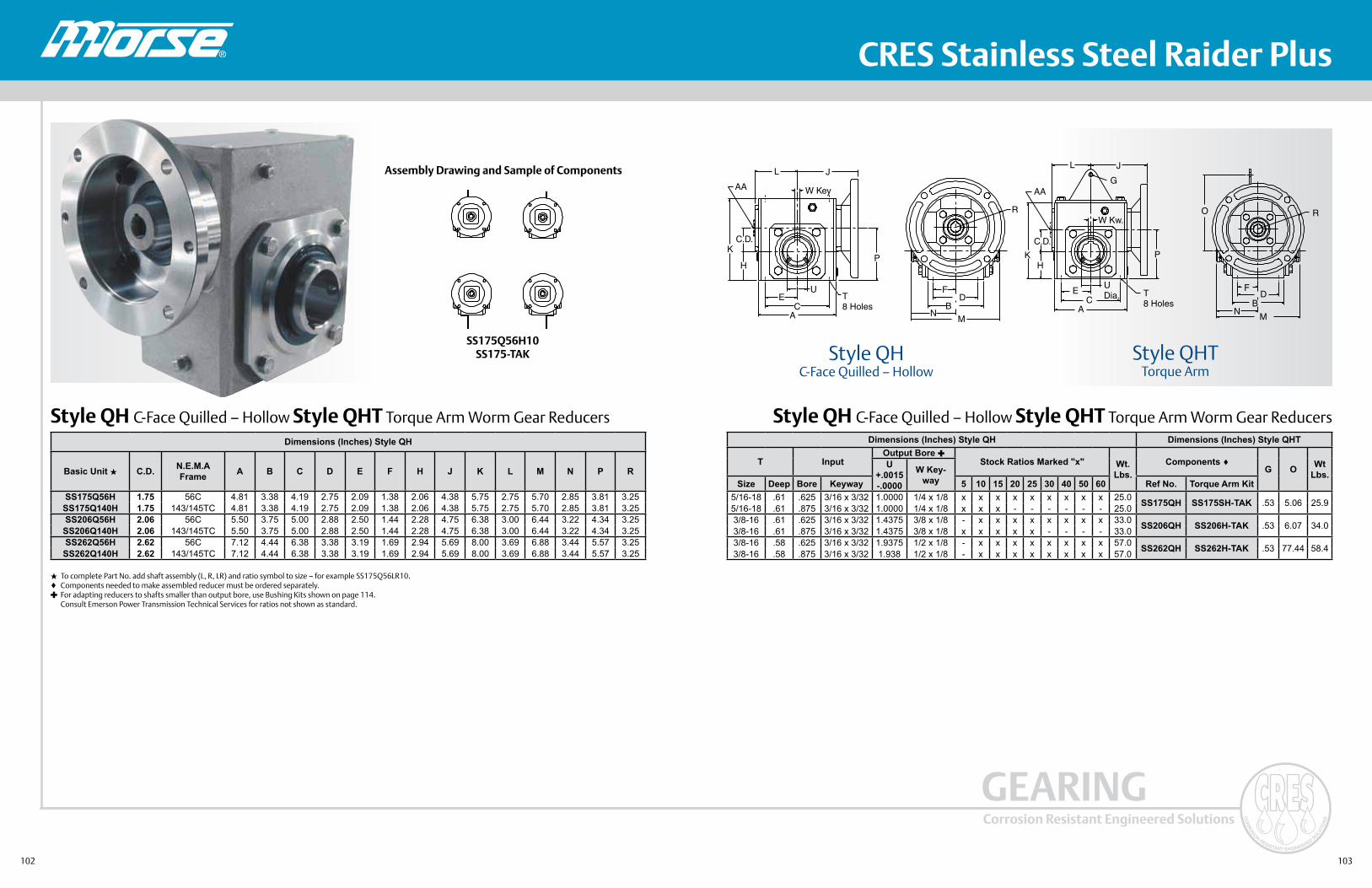
102 103
Corrosion Resistant Engineered Solutions
GEARING
® CRES Stainless Steel Raider Plus
Style QH C-Face Quilled – Hollow Style QHT Torque Arm Worm Gear Reducers
Style QHC-Face Quilled – Hollow
Assembly Drawing and Sample of Components
SS175Q56H10SS175-TAK
Style QH C-Face Quilled – Hollow Style QHT Torque Arm Worm Gear Reducers
To complete Part No. add shaft assembly (L, R, LR) and ratio symbol to size – for example SS175Q56LR10. Components needed to make assembled reducer must be ordered separately. For adapting reducers to shafts smaller than output bore, use Bushing Kits shown on page 114. Consult Emerson Power Transmission Technical Services for ratios not shown as standard.
Dimensions (Inches) Style QH
Basic Unit C.D. N.E.M.A Frame A B C D E F H J K L M N P R
SS175Q56H 1.75 56C 4.81 3.38 4.19 2.75 2.09 1.38 2.06 4.38 5.75 2.75 5.70 2.85 3.81 3.25SS175Q140H 1.75 143/145TC 4.81 3.38 4.19 2.75 2.09 1.38 2.06 4.38 5.75 2.75 5.70 2.85 3.81 3.25SS206Q56H 2.06 56C 5.50 3.75 5.00 2.88 2.50 1.44 2.28 4.75 6.38 3.00 6.44 3.22 4.34 3.25SS206Q140H 2.06 143/145TC 5.50 3.75 5.00 2.88 2.50 1.44 2.28 4.75 6.38 3.00 6.44 3.22 4.34 3.25SS262Q56H 2.62 56C 7.12 4.44 6.38 3.38 3.19 1.69 2.94 5.69 8.00 3.69 6.88 3.44 5.57 3.25SS262Q140H 2.62 143/145TC 7.12 4.44 6.38 3.38 3.19 1.69 2.94 5.69 8.00 3.69 6.88 3.44 5.57 3.25
Dimensions (Inches) Style QH Dimensions (Inches) Style QHT
T InputOutput Bore
Stock Ratios Marked "x" Wt. Lbs.
Components G O Wt
Lbs.U
+.0015-.0000
W Key-waySize Deep Bore Keyway 5 10 15 20 25 30 40 50 60 Ref No. Torque Arm Kit
5/16-18 .61 .625 3/16 x 3/32 1.0000 1/4 x 1/8 x x x x x x x x x 25.0 SS175QH SS175SH-TAK .53 5.06 25.95/16-18 .61 .875 3/16 x 3/32 1.0000 1/4 x 1/8 x x x - - - - - - 25.03/8-16 .61 .625 3/16 x 3/32 1.4375 3/8 x 1/8 - x x x x x x x x 33.0 SS206QH SS206H-TAK .53 6.07 34.03/8-16 .61 .875 3/16 x 3/32 1.4375 3/8 x 1/8 x x x x x - - - - 33.03/8-16 .58 .625 3/16 x 3/32 1.9375 1/2 x 1/8 - x x x x x x x x 57.0 SS262QH SS262H-TAK .53 77.44 58.43/8-16 .58 .875 3/16 x 3/32 1.938 1/2 x 1/8 - x x x x x x x x 57.0
AA
L J
C.D.K
H
EC
A
T8 Holes
U
P
W Key
R
FD
NM
B
AA
L J
G
K
C.D.
P
T8 Holes
UDia.E
CA
W Kw.
F
NM
R
D
O
B
H
Style QHTTorque Arm

104 105
Corrosion Resistant Engineered Solutions
GEARING
® CRES Stainless Steel Raider Plus
SS Raider Plus Stainless Accessories
Table 1 Bushings for SS Raider Plus Hollow Shaft Reducers
Table 2 Dimensions for Torque Arm Kit
Table 3 Dimensions for Adjustable Torque Arm Kit
Table 4 Dimensions for Solid Horizontal One Piece Base
E Dia.
F. Dia.D
B
A C
I
AD
K
L DIA.
M DIA.
J
E
F
HG
B
C
B
G
C
A
H
F DIA
S BOLT
Reducer C.D. Shaft Dia. Shaft Keyseat Bushing Kit No. Wt. Lbs.
1.753/4 3/16 x 3/32 x 1 1 /8 SS100BU012 .37/8 3/16 x 3/32 x 1 1/8 SS100BU014 .1
15/16 1/4 x 1/8 x 1 1/8 SS100BU015 .1
2.06
3/4 3/16 x 3/32 x 2 SS107BU012 1.47/8 3/16 x 3/32 x 2 SS107BU014 1.2
15/16 1/4 x 1/8 x 2 SS107BU015 1.11 1/4 x 1/8 x 2 SS107BU100 1.0
1 11/16 1/4 x 1/8 x 2 SS107BU101 .91 1/8 1/4 x 1/8 x 2 SS107BU102 .81 3/16 1/4 x 1/8 x 2 SS107BU103 .61 1/4 1/4 x 1/8 x 2 SS107BU104 .51 5/16 5/16 x 5/32 x 2 SS107BU105 .4
2.62
15/16 1/4 x 1/8 x 2 1/2 SS115BU015 3.21 1/4 x 1/8 x 2 1/2 SS115BU100 3.1
1 1/6 1/4 x 1/8 x 2 1/2 SS115BU101 3.01 1/8 1/4 x 1/8 x 2 1/2 SS115BU102 2.81 3/16 1/4 x 1/8 x 2 1/2 SS115BU103 2.71 1/4 1/4 x 1/8 x 2 1/2 SS115BU104 2.51 5/16 5/16 x 5/32 x 2 1/2 SS115BU105 2.31 3/8 5/16 x 5/32 x 2 1/2 SS115BU106 2.11 7/16 3/8 x 3/16 x 2 1/2 SS115BU107 1.91 1/2 3/8 x 3/16 x 2 1/2 SS115BU108 1.71 5/8 3/8 x 3/16 x 2 1/2 SS115BU110 1.3
1 11/16 3/8 x 3/16 x 2 1/2 SS115BU111 1.11 3/4 3/8 x 3/16 x 2 1/2 SS115BU112 .8
Part No. A B C D E F Wt./Lbs.SS175-TAK 4.19 2.09 .95 1.38 .53 .344 .9SS206-TAK 5.00 2.50 1.28 1.97 53 .406 1.0SS262-TAK 6.38 3.19 1.131 2.38 .53 .406 1.4
Part No. A B C F G H S Wt./Lbs.SS175-262ATAK 1.38 4.187 .187 .34 4.81 12.00 - 17.50 5/16 2.0
Part No. A B C D E F G H I J K L Dia. M Dia.SS175-BK .62 5.75 7.00 .53 4.50 5.56 1.41 4.19 1.40 2.75 .69 3.8 .44SS206-BK .66 6.38 7.69 .53 4.69 5.76 1.35 5.00 1.44 2.88 .72 .44 .50SS262-BK .63 8.00 9.25 .62 5.25 6.50 1.44 6.38 1.56 3.38 .75 .44 .56

106 107
Corrosion Resistant Engineered Solutions
GEARING
® CRES Stainless Steel Raider Plus
State-of-the-Art Features Built into EveryPaint Free Washdown Motor
Stainless steel frame,thru-bolts, nuts andscrews help prevent rustdue to moisture.
Laser-etched oversized name-plate is easy to readand will not trap food particles or dirt.
Inverter Grade® insulation sys-tem for use with adjustable fre-quency drives enables improved efficiency and control.
T-type drains help prevent need to remove plugs after installa-tion and allow for all-position mounting.
“VBX” Inpro/Seal™ bearing isolator on drive end helps protect against water and contaminants.
303 stainless shaft helps prevent connected drivecomponents from rusting to shaft.
Rust inhibitor on stator and rotor provides added protection against corrosion.
Double-contact, doublesealed ball bearings and moisture-resistant grease helpassure long bearing life.
RTV-sealed exit holes help eliminate a major point of water entry.
Easy-to-read connection leads make wiring easier.
Waterproof nitrile gasket helps prevent moisture and chemi-cals from entering the wiring assembly.
Inverter Grade is a registered trademark of Emerson Electric Co.
C-Face without Base – 1725 RPM
Input Horsepower, Output Torque, Overhung Loads and Thrust Loads for C-Flange Single Reduction Worm Gear Reducers and A.C. Motors
1.00 SFREDUCER PART NUMBER MOTOR HP MOTOR PART NUMBER OUTPUT TORQUE IN.-LBS.
OUTPUT SHAFTMAX. OVERHUNG LOAD
- LBS. MAX. THRUST LOAD - LBS.
1750 R.P.M. Driver - 5:1 Ratio - 350 R.P.M. OutputSS175Q56 1/2 WDP12S2ACR 83 663 868SS175Q56 3/4 WDP34S2ACR 124 663 868SS175Q56 1 WDP1S2AFCR 165 663 868SS175Q140 1 WDP1S2ACR 165 663 868SS175Q56 1 1/2 WDP32S2AFCR 248 663 868SS175Q140 1 1/2 WDP32S2ACR 248 663 868SS206Q56 2 WDP2S2AFCR 335 913 1265SS206Q140 2 WDP2S2ACR 335 913 1265
1750 R.P.M. Driver - 10:1 Ratio - 175 R.P.M. OutputSS175Q56 1/2 WDP12S2ACR 162 740 1098SS206Q56 1/2 WDP12S2ACR 162 1078 1580SS175Q56 3/4 WDP34S2ACR 244 740 1098SS206Q56 3/4 WDP34S2ACR 244 1078 1580SS175Q56 1 WDP1S2AFCR 325 740 1098SS175Q140 1 WDP1S2ACR 325 740 1098SS206Q56 1 1/2 WDP32S2AFCR 489 1078 1580SS206Q140 1 1/2 WDP32S2ACR 489 1078 1580SS262Q56 2 WDP2S2AFCR 657 1295 1976SS262Q140 2 WDP2S2ACR 657 1295 1976
1750 R.P.M. Driver - 15:1 Ratio - 116.6 R.P.M. OutputSS175Q56 1/2 WDP12S2ACR 233 740 1253SS206Q56 1/2 WDP12S2ACR 238 1078 1820SS175Q56 3/4 WDP34S2ACR 350 740 1253SS206Q56 3/4 WDP34S2ACR 357 1078 1820SS206Q56 1 WDP1S2AFCR 475 1078 1820SS206Q140 1 WDP1S2ACR 475 1078 1820SS262Q56 1 1/2 WDP32S2AFCR 719 1295 2296SS262Q140 1 1/2 WDP32S2ACR 719 1295 2296SS262Q56 2 WDP2S2AFCR 959 1295 2296SS262Q140 2 WDP2S2ACR 959 1295 2296
1750 R.P.M. Driver - 20:1 Ratio - 87.5 R.P.M. OutputSS175Q56 1/2 WDP12S2ACR 303 740 1358SS206Q56 1/2 WDP12S2ACR 303 1078 1980SS175Q56 3/4 WDP34S2ACR 455 740 1358SS206Q56 3/4 WDP34S2ACR 455 1078 1980SS206Q56 1 WDP1S2AFCR 609 1078 1980SS206Q140 1 WDP1S2ACR 609 1078 1980SS262Q56 1 1/2 WDP32S2AFCR 930 1295 2536SS262Q140 1 1/2 WDP32S2ACR 930 1295 2536
1750 R.P.M. Driver - 25:1 Ratio - 70 R.P.M. OutputSS175Q56 1/2 WDP12S2ACR 357 740 1380SS206Q56 1/2 WDP12S2ACR 357 1078 2143SS206Q56 3/4 WDP34S2ACR 535 1078 2143SS262Q56 3/4 WDP34S2ACR 548 1295 2748SS262Q56 1 WDP1S2AFCR 730 1295 2748SS262Q140 1 WDP1S2ACR 730 1295 2748SS262Q56 1 1/2 WDP32S2AFCR 1095 1295 2748SS262Q140 1 1/2 WDP32S2ACR 1095 1295 2748
1750 R.P.M. Driver - 30:1 Ratio - 58.3 R.P.M. OutputSS175Q56 1/2 WDP12S2ACR 429 740 1399SS206Q56 1/2 WDP12S2ACR 429 1078 2300SS206Q56 3/4 WDP34S2ACR 647 1078 2300SS262Q56 3/4 WDP34S2ACR 660 1295 2956SS262Q56 1 WDP1S2AFCR 880 1295 2956SS262Q140 1 WDP1S2ACR 880 1295 2956
1750 R.P.M. Driver - 40:1 Ratio - 43.7 R.P.M. OutputSS206Q56 1/2 WDP12S2ACR 534 1078 2305SS262Q56 1/2 WDP12S2ACR 544 1295 3096SS262Q56 3/4 WDP34S2ACR 816 1295 3096SS262Q56 1 WDP1S2AFCR 1088 1295 3096SS262Q140 1 WDP1S2ACR 1088 1295 3096
1750 R.P.M. Driver - 50:1 Ratio - 35 R.P.M. OutputSS206Q56 1/2 WDP12S2ACR 628 1078 2305SS262Q56 1/2 WDP12S2ACR 651 1295 3336SS262Q56 3/4 WDP34S2ACR 976 1295 3336
1750 R.P.M. Driver - 60:1 Ratio - 29.1 R.P.M. OutputSS262Q56 1/2 WDP12S2ACR 748 1295 3410
CATALOG NUMBER HP VOLTS NEMA
FRAME SF AMPS
OVERALL LENGTH
INCLUDING SHAFT
SHAFT DIA. SHAFT LENGTH SHIP WGT
WDP12S2ACR 1/2 208-230/460 56C 1.15 2.0-1.9/0.9 12.2 .625 2.06 36WDP34S2ACR 3/4 208-230/460 56C 1.15 2.8-2.7/1.3 12.2 .625 2.06 37WDP1S2AFCR 1 208-230/460 56C 1.15 3.5-3.4/1.7 13.7 .625 2.06 38WDP1S2ACR 1 208-230/460 145TC 1.15 3.5-3.4/1.7 13.8 .875 2.13 38
WDP32S2AFCR 1 1/2 208-230/460 56C 1.00 4.9-4.8/2.4 13.7 .625 2.06 39WDP32S2ACR 1 1/2 208-230/460 145TC 1.00 4.9-4.8/2.4 13.8 .875 2.13 39WDP2S2AFCR 2 208-230/460 56C 1.15 7.0-7.0/3.5 14.00 .625 1.90 44WDP2S2ACR 2 208-230/460 145TC 1.15 7.0-7.0/3.5 14.10 .875 1.90 44

108 109
Corrosion Resistant Engineered Solutions
GEARING
® CRES Stainless Steel Raider Plus
Input Horsepower, Output Torque, Overhung Loads and Thrust Loads for C-Flange Single Reduction Worm Gear Reducers and A.C. Motors
1.50 SF
Input Horsepower, Output Torque, Overhung Loads and Thrust Loads for C-Flange Single Reduction Worm Gear Reducers and A.C. Motors
2.0 SF
For 1.25 and 1.75 SF contact Emerson Power Transmission Services at 1-800-626-2093.
REDUCER PART NUMBER MOTOR HP MOTOR PART NUMBER OUTPUT TORQUE IN.-
LBS.
OUTPUT SHAFTMAX. OVERHUNG
LOAD - LBS.MAX. THRUST LOAD - LBS.
1750 R.P.M. Driver - 5:1 Ratio - 350 R.P.M. OutputSS175Q56 1/2 WDP12S2ACR 83 663 868SS175Q56 3/4 WDP34S2ACR 124 663 868SS175Q56 1 WDP1S2AFCR 165 663 868
SS175Q140 1 WDP1S2ACR 165 663 868SS206Q140 1 1/2 WDP32S2ACR 251 913 1265SS206Q140 2 WDP2S2ACR 335 913 1265
1750 R.P.M. Driver - 10:1 Ratio - 175 R.P.M. OutputSS175Q56 1/2 WDP12S2ACR 162 740 1098SS206Q56 1/2 WDP12S2ACR 162 1078 1580SS175Q56 3/4 WDP34S2ACR 244 740 1098SS206Q56 3/4 WDP34S2ACR 244 1078 1580SS206Q56 1 WDP1S2AFCR 326 1078 1580
SS206Q140 1 WDP1S2ACR 326 1295 1976SS262Q56 1 1/2 WDP32S2AFCR 493 1295 1976SS262Q140 1 1/2 WDP32S2ACR 493 1295 1976SS262Q56 2 WDP2S2AFCR 657 1295 1976
SS262Q140 2 WDP2S2ACR 657 1295 19761750 R.P.M. Driver - 15:1 Ratio - 116.6 R.P.M. Output
SS175Q56 1/2 WDP12S2ACR 233 740 1253SS206Q56 1/2 WDP12S2ACR 237 1078 1820SS206Q56 3/4 WDP34S2ACR 357 1078 1820SS262Q56 3/4 WDP34S2ACR 360 1295 2296SS262Q56 1 WDP1S2AFCR 480 1295 2296
SS262Q140 1 WDP1S2ACR 480 1295 2296SS262Q56 1 1/2 WDP32S2AFCR 719 1295 2296SS262Q140 1 1/2 WDP32S2ACR 719 1295 2296
1750 R.P.M. Driver - 20:1 Ratio - 87.5 R.P.M. OutputSS175Q56 1/2 WDP12S2ACR 303 740 1358SS206Q56 1/2 WDP12S2ACR 304 1078 1980SS206Q56 3/4 WDP34S2ACR 456 1078 1980SS262Q56 3/4 WDP34S2ACR 465 1295 2536SS262Q56 1 WDP1S2AFCR 620 1295 2536
SS262Q140 1 WDP1S2ACR 620 1295 25361750 R.P.M. Driver - 25:1 Ratio - 70 R.P.M. Output
SS206Q56 1/2 WDP12S2ACR 356 1078 2143SS262Q56 1/2 WDP12S2ACR 365 1295 2748SS262Q56 3/4 WDP34S2ACR 548 1295 2748SS262Q56 1 WDP1S2AFCR 730 1295 2748
SS262Q140 1 WDP1S2ACR 730 1295 27481750 R.P.M. Driver - 30:1 Ratio - 58.3 R.P.M. Output
SS206Q56 1/2 WDP12S2ACR 431 1078 2300SS262Q56 1/2 WDP12S2ACR 440 1295 2956SS262Q56 3/4 WDP34S2ACR 660 1295 2956
1750 R.P.M. Driver - 40:1 Ratio - 43.7 R.P.M. OutputSS262Q56 1/2 WDP12S2ACR 544 1295 3096SS262Q56 3/4 WDP34S2ACR 816 1295 3096
1750 R.P.M. Driver - 50:1 Ratio - 35 R.P.M. OutputSS262Q56 1/2 WDP12S2ACR 651 1295 3336
1750 R.P.M. Driver - 60:1 Ratio - 29.1 R.P.M. OutputSS262Q56 1/2 WDP12S2ACR 748 1295 3410
REDUCER PART NUMBER MOTOR HP MOTOR PART NUMBER OUTPUT TORQUE IN.-
LBS.
OUTPUT SHAFTMAX. OVERHUNG LOAD
- LBS.MAX. THRUST LOAD
- LBS.1750 R.P.M. Driver - 5:1 Ratio - 350 R.P.M. Output
SS175Q56 1/2 WDP12S2ACR 83 663 868SS175Q56 3/4 WDP34S2ACR 124 663 868SS175Q56 1 WDP1S2AFCR 165 663 868
SS175Q140 1 WDP1S2ACR 165 663 868SS206Q140 1 1/2 WDP32S2ACR 252 913 1265SS262Q56 2 WDP2S2AFCR 338 1295 1596
1750 R.P.M. Driver - 10:1 Ratio - 175 R.P.M. OutputSS175Q56 1/2 WDP12S2ACR 162 740 1098SS206Q56 1/2 WDP12S2ACR 162 1078 1580SS206Q56 3/4 WDP34S2ACR 244 1078 1580SS262Q56 1 WDP1S2AFCR 328 1295 1976
SS262Q140 1 WDP1S2ACR 328 1295 1976SS262Q56 1 1/2 WDP32S2AFCR 493 1295 1976
SS262Q140 1 1/2 WDP32S2ACR 493 1295 19761750 R.P.M. Driver - 15:1 Ratio - 116.6 R.P.M. Output
SS206Q56 1/2 WDP12S2ACR 238 1078 1820SS262Q56 1/2 WDP12S2ACR 238 1295 2296SS262Q56 3/4 WDP34S2ACR 360 1295 2296SS262Q56 1 WDP1S2AFCR 480 1295 2296
SS262Q140 1 WDP1S2ACR 480 1295 22961750 R.P.M. Driver - 20:1 Ratio - 87.5 R.P.M. Output
SS206Q56 1/2 WDP12S2ACR 304 1078 1980SS262Q56 1/2 WDP12S2ACR 304 1295 2536SS262Q56 3/4 WDP34S2ACR 465 1295 2536SS262Q56 1 WDP1S2AFCR 620 1295 2536
SS262Q140 1 WDP1S2ACR 620 1295 25361750 R.P.M. Driver - 25:1 Ratio - 58.3 R.P.M. Output
SS262Q56 1/2 WDP12S2ACR 365 1295 2748SS262Q56 3/4 WDP34S2ACR 548 1295 2748
1750 R.P.M. Driver - 30:1 Ratio - 70 R.P.M. OutputSS262Q56 1/2 WDP12S2ACR 440 1295 2956
1750 R.P.M. Driver - 40:1 Ratio - 43.7 R.P.M. OutputSS262Q56 1/2 WDP12S2ACR 544 1295 3096

110 111
Corrosion Resistant Engineered Solutions
GEARING
®
Corrosion – Resistant Coatings
These corrosion-resistant coating options are available today in all sizes for the complete line of Browning and Morse speed reducers and gearmotors. They complement our premium corrosion-resistant engineered solutions, including all the stainless steel Morse Raider Plus offerings for the ultimate in corrosion resistance.
Coatings USDA and FDA Accepted
CRESA rugged, three -step process produces a superb corrosion duty coating that works well in wet, corrosion environments. The metallic gray coating is USDA and FDA accepted with a 316 stainless steel pigment.
316 Stainless Steel Coating – Corro-Duty Gray
This two-step coatings is the traditional food-grade white epoxy often used in demanding, corrosive food and beverage applications and is also USDA and FDA accepted.
White Epoxy Coating – Corro-Duty White
Please specify Corro-Duty Gray or Corro-Duty Whitewhen ordering.
Available on: • Worm Gear Reducers and Gearmotors • Helical In-Line and Right Angle Speed Reducers and
Gearmotors
• Do your applications include food, chemical, or poultry processing?
• Is your equipment outdoors and exposed to the elements?
• Are your gearing products subjected to extreme humidity, washdown, steam, caustic detergents or mild acids?
Call Emerson Power Transmissionfor your Corrosion-Resistant Gearing Solutions.
1-800-626-2120
Expanded, Corrosion-Resistant Coatings
316 Stainless Steel Coating – Corro-Duty Gray
White Epoxy Coating – Corro-Duty White
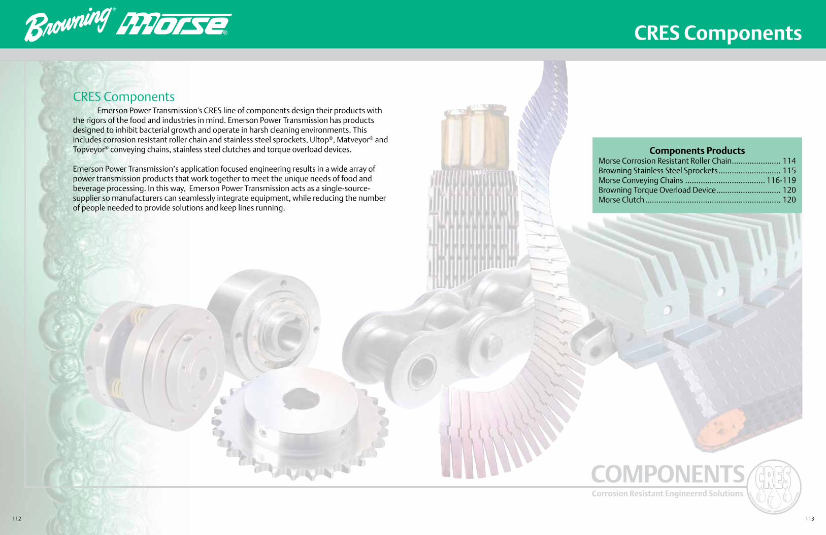
112 113
Corrosion Resistant Engineered Solutions
COMPONENTS
®
®
CRES Components
Components ProductsMorse Corrosion Resistant Roller Chain ...................... 114Browning Stainless Steel Sprockets ............................ 115Morse Conveying Chains .................................... 116-119Browning Torque Overload Device ............................. 120Morse Clutch ............................................................. 120
Emerson Power Transmission's CRES line of components design their products with the rigors of the food and industries in mind. Emerson Power Transmission has products designed to inhibit bacterial growth and operate in harsh cleaning environments. This includes corrosion resistant roller chain and stainless steel sprockets, Ultop®, Matveyor® and Topveyor® conveying chains, stainless steel clutches and torque overload devices.
Emerson Power Transmission’s application focused engineering results in a wide array of power transmission products that work together to meet the unique needs of food and beverage processing. In this way, Emerson Power Transmission acts as a single-source-supplier so manufacturers can seamlessly integrate equipment, while reducing the number of people needed to provide solutions and keep lines running.
CRES Components

114 115
Corrosion Resistant Engineered Solutions
COMPONENTS
®
Morse provides a wide range of high quality roller chain solutions to meet application needs for many different industries. With 100 years of experience in manufacturing domestic chain products that meet or exceed industry standard; Morse delivers exceptional customer value.
Morse offers several corrosion resistant roller chain solutions to help customers with challenging applications in harsh environments.
MORSE Roller Chain
CRES Nickel Plated Roller Chain • High quality nickel plating applied to chain parts prior to assembly
• Outstanding appearance and corrosion resistance
• Many sizes available from stock, with or without attachments – other sizes and special attachments available upon request
Stainless Steel Roller Chain • 300 Series stainless steel for the most corrosive environments
• Stocked in 25 through 120, including popular attachments – other sizes and special attachments also available
Corrosion Resistant Attachment Chain • Available in standard carbon steel, nickel plated, Moisture Guard, stainless steel and custom designs on a
made-to-order basis
Stainless Steel Sprockets • Provides a complete, corrosion resistant chain drive with stainless steel sprockets
• Available in 35 through 80 pitch in A-plate and B-plate styles
• Popular sizes stocked
• Custom sprockets also available to meet the most challenging applications
For customer service, contact the Specialty Chain Center at 1-888-378-7223
For customized chain solutions, contact Application Engineering at 1-800-626-2093or by email at [email protected] to solve your chain corrosion problems
CRES Roller Chain
Moisture Guard® Chain • Corrosion protection with high strength and wear resistance
• Plated before assembly for through corrosion protection
• Custom Moisture Guard chain available for design according to your application needs for materials, platings, coatings and lubricants
• Stocked in 35 through 80 pitch in 10 ft. packages or cut-to-length How to Order: Simply add an MG after the pitch size. For example, order 60MG R for 60 pitch riveted Moisture Guard Chain.
ASTMB-117 • 500 Hour Salt Spray Test
Competitor “Water Proof” Chain Morse Moisture Guard® Chain
Chain TypesMorse provides corrosion resistant materials for most chain styles.

116 117
Corrosion Resistant Engineered Solutions
COMPONENTS
® CRES Conveying Chains
MORSE Conveying Chains
CRES
Morse offers three lines of fully-integrated conveying chains. These high quality, high performance systems handle a multiplicity of tough container handling tasks and offers optimum versatility, variety and value.
1. Ultop Family of Conveyor Chain 2. Matveyor Modular Plastic Chain 3. Topveyor Conveying Chain
Ultop Chain Matveyor Chain Topveyor Chain
Ultop ChainThe ultimate in container handling! Built for speed and smooth performance. To Address today’s Hot Issues in beverage plants.
• Increased speed of production lines
• Improved product stability, even with light weight products
• Dry running, eliminate soap lubricants
• Reduced downtime and maintenance
• Active Transfer Modules for smooth, continuous product transfer at 90 degree corners
Matveyor ChainBrickable width plastic belting with performance materials to match challenging conveying applications.
• Series 1010 Light duty 1" pitch products ideally suited to a wide variety of general package and container handling applications
• Series 3000 Heavy duty 2" pitch belts applicable for larger warmers, coolers, mass accumulation, and general conveying
• Series 5000 Modularity in a turn-style belt ideal for many food production and processing applications
Topveyor ChainThe TOP choice for problem-solving. Tops in interchangeability and specialty chain choices.
• Carbon and stainless steel chains
• Advanced thermoplastic materials
• Straight running, side flexing and multi-flex
• Split and solid sprockets

118 119
Corrosion Resistant Engineered Solutions
COMPONENTS
®
MORSE Gripper Chain
CRES
For your bottle handling applications consider Morse gripper chain. Flexible, rubber grippers maintain their original shape and elasticity and are specifically designed to exert the appropriate amount of force onto containers. The proprietary flight material also decreases forces on chain flights, reducing chain pull and dramatically increasing base chain life. Additionally, stainless steel pins hold grippers to flights, and keep them from coming off during machine jams.
Thermoplastic, Rubber Chain • Flexible, thermoplastic, rubber retains memory so grippers return to their original shape and
consistency
• Grippers available with shorter fingers that exert a higher force on conveyed products — particularly suitable for heavier containers and packaged products
• Fingers flex without increasing force on the product and the conveyor — making it suitable for conveying glass containers
• Some models offers a flat, more continuous contact surface between the rubber and the conveyed product
Base Roller Chain • 3/4" pitch
• Carbon steel for mechanical strength and resistance to elongation
• Stainless steel for mechanical strength and corrosion resistance
Benefit Summary • Gripper chain exerts the right amount of force so container deformation is not an issue
• Pliable rubber grippers retain shape and consistency
• Grippers securely fastened to flight by a stainless steel pin that helps eliminate pop-offs and provides smooth, rapid movement
• Fingers cover a larger area of containers — providing better handling abilities
• Stainless and carbon steel base chain options for mechanical strength and corrosion resistance
• DK flights provide excellent wear resistance, help reduce elongation of stainless steel base chain and result in less dusting
CRES Gripper Chain
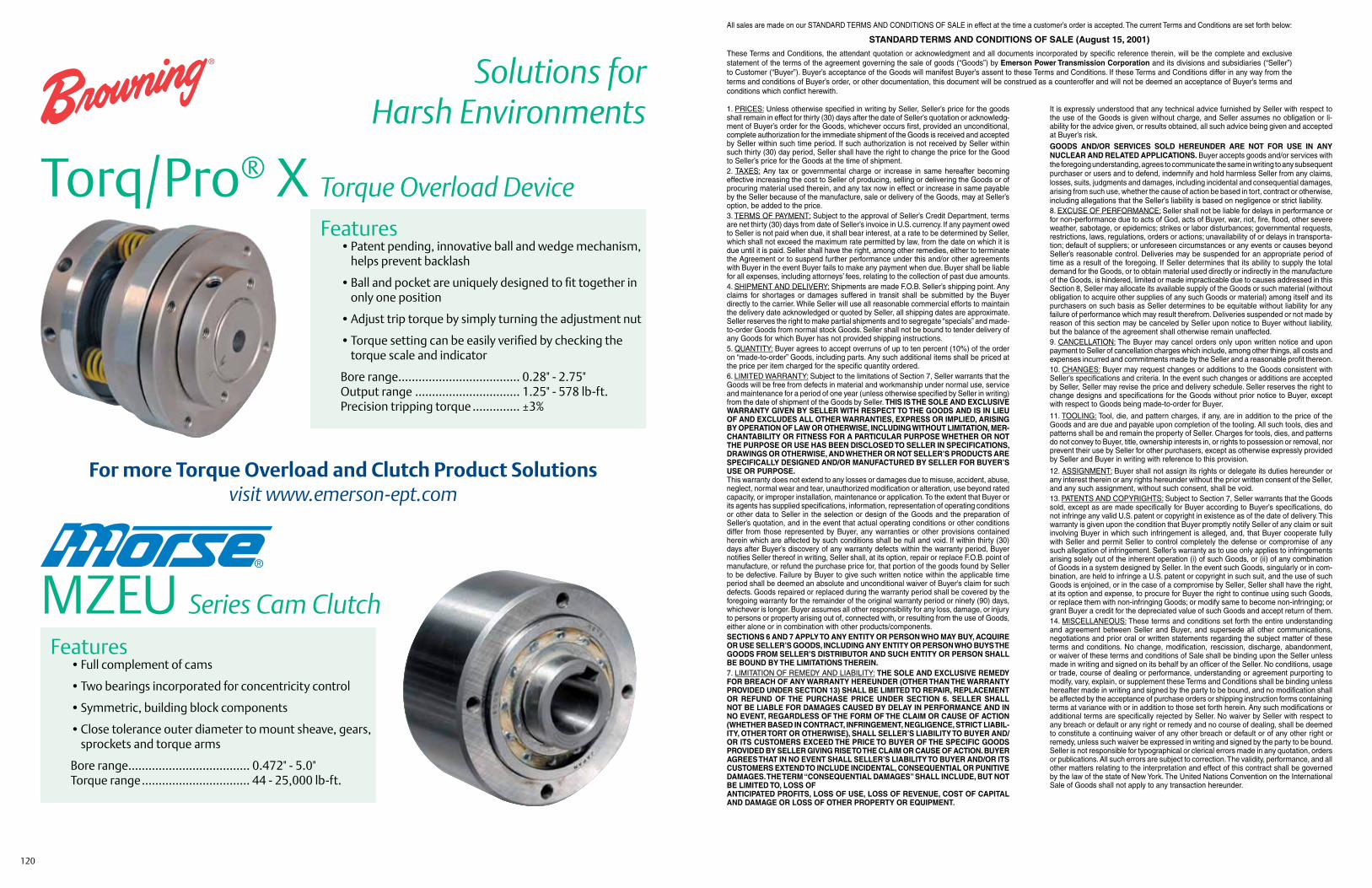
120
Solutions forHarsh Environments
Torq/Pro® X Torque Overload DeviceFeatures • Patent pending, innovative ball and wedge mechanism,
helps prevent backlash
• Ball and pocket are uniquely designed to fit together in only one position
• Adjust trip torque by simply turning the adjustment nut
• Torque setting can be easily verified by checking the torque scale and indicator
Bore range .................................... 0.28" - 2.75" Output range ............................... 1.25" - 578 lb-ft. Precision tripping torque .............. ±3%
MZEU Series Cam Clutch
Features • Full complement of cams
• Two bearings incorporated for concentricity control
• Symmetric, building block components
• Close tolerance outer diameter to mount sheave, gears, sprockets and torque arms
Bore range .................................... 0.472" - 5.0" Torque range ................................ 44 - 25,000 lb-ft.
1. PRICES: Unless otherwise specified in writing by Seller, Seller’s price for the goods shall remain in effect for thirty (30) days after the date of Seller’s quotation or acknowledg-ment of Buyer’s order for the Goods, whichever occurs first, provided an unconditional, complete authorization for the immediate shipment of the Goods is received and accepted by Seller within such time period. If such authorization is not received by Seller within such thirty (30) day period, Seller shall have the right to change the price for the Good to Seller’s price for the Goods at the time of shipment.2. TAXES: Any tax or governmental charge or increase in same hereafter becoming effective increasing the cost to Seller of producing, selling or delivering the Goods or of procuring material used therein, and any tax now in effect or increase in same payable by the Seller because of the manufacture, sale or delivery of the Goods, may at Seller’s option, be added to the price.3. TERMS OF PAYMENT: Subject to the approval of Seller’s Credit Department, terms are net thirty (30) days from date of Seller’s invoice in U.S. currency. If any payment owed to Seller is not paid when due, it shall bear interest, at a rate to be determined by Seller, which shall not exceed the maximum rate permitted by law, from the date on which it is due until it is paid. Seller shall have the right, among other remedies, either to terminate the Agreement or to suspend further performance under this and/or other agreements with Buyer in the event Buyer fails to make any payment when due. Buyer shall be liable for all expenses, including attorneys’ fees, relating to the collection of past due amounts.4. SHIPMENT AND DELIVERY: Shipments are made F.O.B. Seller’s shipping point. Any claims for shortages or damages suffered in transit shall be submitted by the Buyer directly to the carrier. While Seller will use all reasonable commercial efforts to maintain the delivery date acknowledged or quoted by Seller, all shipping dates are approximate. Seller reserves the right to make partial shipments and to segregate “specials” and made-to-order Goods from normal stock Goods. Seller shall not be bound to tender delivery of any Goods for which Buyer has not provided shipping instructions.5. QUANTITY: Buyer agrees to accept overruns of up to ten percent (10%) of the order on “made-to-order” Goods, including parts. Any such additional items shall be priced at the price per item charged for the specific quantity ordered.6. LIMITED WARRANTY: Subject to the limitations of Section 7, Seller warrants that the Goods will be free from defects in material and workmanship under normal use, service and maintenance for a period of one year (unless otherwise specified by Seller in writing) from the date of shipment of the Goods by Seller. THIS IS THE SOLE AND EXCLUSIVE WARRANTY GIVEN BY SELLER WITH RESPECT TO THE GOODS AND IS IN LIEU OF AND EXCLUDES ALL OTHER WARRANTIES, EXPRESS OR IMPLIED, ARISING BY OPERATION OF LAW OR OTHERWISE, INCLUDING WITHOUT LIMITATION, MER-CHANTABILITY OR FITNESS FOR A PARTICULAR PURPOSE WHETHER OR NOT THE PURPOSE OR USE HAS BEEN DISCLOSED TO SELLER IN SPECIFICATIONS, DRAWINGS OR OTHERWISE, AND WHETHER OR NOT SELLER’S PRODUCTS ARE SPECIFICALLY DESIGNED AND/OR MANUFACTURED BY SELLER FOR BUYER’S USE OR PURPOSE.This warranty does not extend to any losses or damages due to misuse, accident, abuse, neglect, normal wear and tear, unauthorized modification or alteration, use beyond rated capacity, or improper installation, maintenance or application. To the extent that Buyer or its agents has supplied specifications, information, representation of operating conditions or other data to Seller in the selection or design of the Goods and the preparation of Seller’s quotation, and in the event that actual operating conditions or other conditions differ from those represented by Buyer, any warranties or other provisions contained herein which are affected by such conditions shall be null and void. If within thirty (30) days after Buyer’s discovery of any warranty defects within the warranty period, Buyer notifies Seller thereof in writing, Seller shall, at its option, repair or replace F.O.B. point of manufacture, or refund the purchase price for, that portion of the goods found by Seller to be defective. Failure by Buyer to give such written notice within the applicable time period shall be deemed an absolute and unconditional waiver of Buyer’s claim for such defects. Goods repaired or replaced during the warranty period shall be covered by the foregoing warranty for the remainder of the original warranty period or ninety (90) days, whichever is longer. Buyer assumes all other responsibility for any loss, damage, or injury to persons or property arising out of, connected with, or resulting from the use of Goods, either alone or in combination with other products/components.SECTIONS 6 AND 7 APPLY TO ANY ENTITY OR PERSON WHO MAY BUY, ACQUIRE OR USE SELLER’S GOODS, INCLUDING ANY ENTITY OR PERSON WHO BUYS THE GOODS FROM SELLER’S DISTRIBUTOR AND SUCH ENTITY OR PERSON SHALL BE BOUND BY THE LIMITATIONS THEREIN.7. LIMITATION OF REMEDY AND LIABILITY: THE SOLE AND EXCLUSIVE REMEDY FOR BREACH OF ANY WARRANTY HEREUNDER (OTHER THAN THE WARRANTY PROVIDED UNDER SECTION 13) SHALL BE LIMITED TO REPAIR, REPLACEMENT OR REFUND OF THE PURCHASE PRICE UNDER SECTION 6. SELLER SHALL NOT BE LIABLE FOR DAMAGES CAUSED BY DELAY IN PERFORMANCE AND IN NO EVENT, REGARDLESS OF THE FORM OF THE CLAIM OR CAUSE OF ACTION (WHETHER BASED IN CONTRACT, INFRINGEMENT, NEGLIGENCE, STRICT LIABIL-ITY, OTHER TORT OR OTHERWISE), SHALL SELLER’S LIABILITY TO BUYER AND/OR ITS CUSTOMERS EXCEED THE PRICE TO BUYER OF THE SPECIFIC GOODS PROVIDED BY SELLER GIVING RISE TO THE CLAIM OR CAUSE OF ACTION. BUYER AGREES THAT IN NO EVENT SHALL SELLER’S LIABILITY TO BUYER AND/OR ITS CUSTOMERS EXTEND TO INCLUDE INCIDENTAL, CONSEQUENTIAL OR PUNITIVE DAMAGES. THE TERM “CONSEQUENTIAL DAMAGES” SHALL INCLUDE, BUT NOT BE LIMITED TO, LOSS OFANTICIPATED PROFITS, LOSS OF USE, LOSS OF REVENUE, COST OF CAPITAL AND DAMAGE OR LOSS OF OTHER PROPERTY OR EQUIPMENT.
It is expressly understood that any technical advice furnished by Seller with respect to the use of the Goods is given without charge, and Seller assumes no obligation or li-ability for the advice given, or results obtained, all such advice being given and accepted at Buyer’s risk.
GOODS AND/OR SERVICES SOLD HEREUNDER ARE NOT FOR USE IN ANY NUCLEAR AND RELATED APPLICATIONS. Buyer accepts goods and/or services with the foregoing understanding, agrees to communicate the same in writing to any subsequent purchaser or users and to defend, indemnify and hold harmless Seller from any claims, losses, suits, judgments and damages, including incidental and consequential damages, arising from such use, whether the cause of action be based in tort, contract or otherwise, including allegations that the Seller's liability is based on negligence or strict liability.8. EXCUSE OF PERFORMANCE: Seller shall not be liable for delays in performance or for non-performance due to acts of God, acts of Buyer, war, riot, fire, flood, other severe weather, sabotage, or epidemics; strikes or labor disturbances; governmental requests, restrictions, laws, regulations, orders or actions; unavailability of or delays in transporta-tion; default of suppliers; or unforeseen circumstances or any events or causes beyond Seller’s reasonable control. Deliveries may be suspended for an appropriate period of time as a result of the foregoing. If Seller determines that its ability to supply the total demand for the Goods, or to obtain material used directly or indirectly in the manufacture of the Goods, is hindered, limited or made impracticable due to causes addressed in this Section 8, Seller may allocate its available supply of the Goods or such material (without obligation to acquire other supplies of any such Goods or material) among itself and its purchasers on such basis as Seller determines to be equitable without liability for any failure of performance which may result therefrom. Deliveries suspended or not made by reason of this section may be canceled by Seller upon notice to Buyer without liability, but the balance of the agreement shall otherwise remain unaffected.9. CANCELLATION: The Buyer may cancel orders only upon written notice and upon payment to Seller of cancellation charges which include, among other things, all costs and expenses incurred and commitments made by the Seller and a reasonable profit thereon.10. CHANGES: Buyer may request changes or additions to the Goods consistent with Seller’s specifications and criteria. In the event such changes or additions are accepted by Seller, Seller may revise the price and delivery schedule. Seller reserves the right to change designs and specifications for the Goods without prior notice to Buyer, except with respect to Goods being made-to-order for Buyer.
11. TOOLING: Tool, die, and pattern charges, if any, are in addition to the price of the Goods and are due and payable upon completion of the tooling. All such tools, dies and patterns shall be and remain the property of Seller. Charges for tools, dies, and patterns do not convey to Buyer, title, ownership interests in, or rights to possession or removal, nor prevent their use by Seller for other purchasers, except as otherwise expressly provided by Seller and Buyer in writing with reference to this provision.
12. ASSIGNMENT: Buyer shall not assign its rights or delegate its duties hereunder or any interest therein or any rights hereunder without the prior written consent of the Seller, and any such assignment, without such consent, shall be void.13. PATENTS AND COPYRIGHTS: Subject to Section 7, Seller warrants that the Goods sold, except as are made specifically for Buyer according to Buyer’s specifications, do not infringe any valid U.S. patent or copyright in existence as of the date of delivery. This warranty is given upon the condition that Buyer promptly notify Seller of any claim or suit involving Buyer in which such infringement is alleged, and, that Buyer cooperate fully with Seller and permit Seller to control completely the defense or compromise of any such allegation of infringement. Seller’s warranty as to use only applies to infringements arising solely out of the inherent operation (i) of such Goods, or (ii) of any combination of Goods in a system designed by Seller. In the event such Goods, singularly or in com-bination, are held to infringe a U.S. patent or copyright in such suit, and the use of such Goods is enjoined, or in the case of a compromise by Seller, Seller shall have the right, at its option and expense, to procure for Buyer the right to continue using such Goods, or replace them with non-infringing Goods; or modify same to become non-infringing; or grant Buyer a credit for the depreciated value of such Goods and accept return of them.14. MISCELLANEOUS: These terms and conditions set forth the entire understanding and agreement between Seller and Buyer, and supersede all other communications, negotiations and prior oral or written statements regarding the subject matter of these terms and conditions. No change, modification, rescission, discharge, abandonment, or waiver of these terms and conditions of Sale shall be binding upon the Seller unless made in writing and signed on its behalf by an officer of the Seller. No conditions, usage or trade, course of dealing or performance, understanding or agreement purporting to modify, vary, explain, or supplement these Terms and Conditions shall be binding unless hereafter made in writing and signed by the party to be bound, and no modification shall be affected by the acceptance of purchase orders or shipping instruction forms containing terms at variance with or in addition to those set forth herein. Any such modifications or additional terms are specifically rejected by Seller. No waiver by Seller with respect to any breach or default or any right or remedy and no course of dealing, shall be deemed to constitute a continuing waiver of any other breach or default or of any other right or remedy, unless such waiver be expressed in writing and signed by the party to be bound. Seller is not responsible for typographical or clerical errors made in any quotation, orders or publications. All such errors are subject to correction. The validity, performance, and all other matters relating to the interpretation and effect of this contract shall be governed by the law of the state of New York. The United Nations Convention on the International Sale of Goods shall not apply to any transaction hereunder.
All sales are made on our STANDARD TERMS AND CONDITIONS OF SALE in effect at the time a customer’s order is accepted. The current Terms and Conditions are set forth below:
STANDARD TERMS AND CONDITIONS OF SALE (August 15, 2001)
These Terms and Conditions, the attendant quotation or acknowledgment and all documents incorporated by specific reference therein, will be the complete and exclusive statement of the terms of the agreement governing the sale of goods (“Goods”) by Emerson Power Transmission Corporation and its divisions and subsidiaries (“Seller”) to Customer (“Buyer”). Buyer’s acceptance of the Goods will manifest Buyer’s assent to these Terms and Conditions. If these Terms and Conditions differ in any way from the terms and conditions of Buyer’s order, or other documentation, this document will be construed as a counteroffer and will not be deemed an acceptance of Buyer’s terms and conditions which conflict herewith.
For more Torque Overload and Clutch Product Solutionsvisit www.emerson-ept.com