Embed Size (px)
Citation preview
AS-i Master for S7-1200Catalog IC 10 N · December 2011
SIRIUS
Answers for industry.
ic10N_asi-master_s7-1200_umschlag_en.indd 1ic10N_asi-master_s7-1200_umschlag_en.indd 1 25.01.2012 14:27:4825.01.2012 14:27:48
© Siemens AG 2012

All product designations may be registered trademarks or product names of Siemens AG or other supplying companies. Third parties using these trademarks or product names for their own purposes may infringe upon the rights of the trademark owners.
Further information about industrial controls:www.siemens.com/sirius
Related catalogs Contents
Registered trademarks Technical Assistance
Industrial Controls IC 10SIRIUS
E86060-K1010-A101-A2-7600
Safety Integrated SI 10Safety Technology forFactory Automation
E86060-K7010-A101-A2-7600
Industrial Communication IK PISIMATIC NET
E86060-K6710-A101-B7-7600
Products for Automation CA 01and DrivesInteractive Catalog
DVD: E86060-D4001-A510-D1-7600
Industry MallInformation and Ordering Platformin the Internet:
www.siemens.com/industrymall
Catalog PDFInternet:
www.siemens.com/automation/infocenter
Industrial communication · Controls · Protection equipment · Load feeders and motor starters · Monitoring and control devices · Safety control devices · Detecting devices · Com-manding and signaling devices · Parameterization, configura-tion and visualization · Transformers and power supplies · Heating controls · Components for charging electric vehicles
Detecting · Evaluation / Communication · Reacting
PROFINET / Industrial Ethernet · PROFIBUS · SIMATIC ET 200 Distributed I/O · SIMATIC Ident Identification Systems · AS-Interface · IO-Link · Industrial Wireless Communication · Industrial Remote Communication · ECOFAST
All products of automation, drives and installation technology, including those in the catalogs listed above.
All products of automation, drives and installation technology, including those in the catalogs listed above.
Information and download center of Industry Automation and Drive Technologies.
Expert technical assistance for Industrial controls:Tel.: +49 (911) 895-5900Fax: +49 (911) 895-5907
E-Mail: [email protected]
IC10N_122011.book Seite 1 Donnerstag, 2. Februar 2012 4:57 16
© Siemens AG 2012

SIRIUSAS-i Master for S7-1200
Catalog IC 10 N · December 2011
For the latest updates of this catalog, please visit our Industry Mall:www.siemens.com/industrymall
Contact your local Siemens sales office for further information
© Siemens AG 2012
The products and sys-tems listed in this cata-log are manufac-tured/distributed using a certified quality man-agement system which complies with EN ISO 9001 (for the Certificate Register Nos. see the Appendix to the catalog IC 10 · 2012). The certifi-cate is recognized in all IQNet countries.
1 Introduction
2 Industrial Communication
3 Controls – Contactors and Contactor Assemblies –for Starting Motors
4 Controls –Contactors and Contactor Assemblies –Special Applications
5 Controls –Contactors and Contactor Assemblies –Contactor Relays and Relays
6 Controls – Soft Starters and Solid-State Switching Devices
7 Protection Equipment
8 Load Feeders and Motor Starters for Operation in the Control Cabinet
9 Motor Starters for Operation in the Field, High Degree of Protection
10 Monitoring and Control Devices
11 Safety Technology
12 Position Switches and Safety Switches
13 Commanding and Signaling Devices
14 Planning, Configuration and Visualizing for SIRIUS
15 Products for Specific Requirements
16 Appendix
IC10N_122011.book Seite 1 Donnerstag, 2. Februar 2012 4:57 16
© Siemens AG 2012

2 Siemens IC 10 N · 12/2011
SelectingFind your products in the structure tree, in the new "Bread-crumb" navigation or with the integral search machine with expert functions. Electronic configurators are also integrated into the Mall. Enter the various characteristic values and the appropriate product will be dis-played with the relevant order numbers. You can save configurations, load them and reset them to their initial status.
OrderingYou can load the products that you have selected in this way into the shopping basket at a click of the mouse. You can create your own tem-plates and you will be informed about the availability of the products in your shopping cart. You can load the completed parts lists directly into Excel or Word.
Delivery statusWhen you have sent the order, you will receive a short e-mail confir-mation which you can print out or save. With a click on "Carrier", you will be directly connected to the website of the carrier where you can easily track the delivery status.
Added value due to additional informationSo you have found your product and want more information about it? In just a few clicks of the mouse, you will arrive at the image data base, manuals and operating instructions. Create your own user documen-tation with My Documentation Manager.Also available are FAQs, software downloads, certificates and technical data sheets as well as our training programs. In the image database you will find, depending on the product, 2D/3D graphics, dimension drawings and exploded drawings, characteristic curves or circuit diagrams which you can download.
Convinced? We look forward to your visit!
Much more than a catalog.The Industry Mall.
You have a catalog in your hands that will serve you well for selecting and ordering your products. But have you heard of the electronic online cata-log (the Industry Mall) and all its benefits? Take a look around it sometime:
www.siemens.com/industrymall
Industry Mall
IC10N_122011.book Seite 2 Donnerstag, 2. Februar 2012 4:57 16
© Siemens AG 2012

3Siemens IC 10 N · 12/2011
Things you should know about Catalog News IC 10 N
The Catalog News IC 10 N contains all selection and order-relevant data.
Delivery time class (DT)
} Preferred type
A 2 working days
B 1 week
C 3 weeks
D 6 weeks
X On request
Preferred types are available immediately from stock, i. e. are dispatched within 24 hours.
Normal quantities of the products are usually deliv-ered within the specified time following receipt of your order at our branch.
In exceptional cases, the actual delivery time may differ from that specified.
The delivery times apply up to the ramp at Siemens AG (products ready for dispatch). The transport times depend on the destination and type of shipping. The standard transport time for Germany is 1 day.
The delivery time classes specified here represent the state of 10/2010. They are permanently optimized. Up-to-date information can be found atwww.siemens.com/sirius/mall.
Price units (PU)
The price unit defines the number of units, sets or meters to which the specified price and weight apply.
Packaging sizes (PS)
The packaging size defines the number, e. g. of units, sets or meters, for outer packaging.
Only the quantity defined by the packaging size or a multiple thereof can be ordered!
For multi-unit packing and reusable packaging see Appendix in IC 10 · 2012.
Price groups (PG)
Each product is assigned to a price group.
Dimensions
All dimensions in mm.
Ordering notes
IC10N_122011.book Seite 3 Donnerstag, 2. Februar 2012 4:57 16
© Siemens AG 2012

4 Siemens IC 10 N · 12/2011
Notes
IC10N_122011.book Seite 4 Donnerstag, 2. Februar 2012 4:57 16
© Siemens AG 2012

Siemens IC 10 N · 12/2011
2
Siemens IC 10 N · 12/2011
2
Price groupsPG 41B, 41H, 42C, 42D, 42F, 42J, 230, 250, 5K1, 5K2, 5N3
2/2 Introduction
AS-InterfaceIntroduction
2/4 Transmission technology2/5 Communication overview
AS-Interface specification2/6 - Specification 2.0, 2.1 and 3.02/7 - AS-i Power24V expansion
MastersMasters for SIMATIC S7
2/8 - CM 1243-2 2/10 - CP 243-22/11 - CP 343-2P / CP 343-2
Power supply units and data decoupling modules
2/13 AS-Interface power supply unitsCh.15 24 V power supply units2/14 S22.5 data decoupling modules
Data decoupling modules for S7-12002/16 - DCM 1271 data decoupling module
1) See Catalog DA 11.1
More information is available on the Internet, see the opening information in IC 10 · 2012, page 16
Industrial Communication
IC10N_122011.book Seite 1 Donnerstag, 2. Februar 2012 4:57 16
© Siemens AG 2012

Industrial Communication
Introduction
2/2 Siemens IC 10 N · 12/2011
2
■ Overview
Order No. Page
AS-Interface: MastersThe AS-Interface master connects SIMATIC control systems to AS-Interface. It automatically organizes the data traffic on the AS-Interface cable and sees not only to processing the sig-nals but also to performing the parameter setting, monitoring and diagnostics functions.
CM 1243-2 for SIMATIC S7-1200
CP 343-2, CP 343-2P for SIMATIC S7-300
CP 243-2 for SIMATIC S7-200
Masters for SIMATIC S7
• Connection of up to 62 AS-Interface slaves
• Connection of up to 496 digital inputs and 496 outputs per master or AS-Interface network
• Integrated analog value transmission
• Simple configuration by adopting the actual configuration on the AS-Interface network
• Easy operation in the input/output address area of the SIMATIC S7 comparable to standard I/O modules
• Monitoring of the control supply voltage on the AS-Interface shaped cable
Your advantage: Easy connection to SIMATIC S7-300, ET 200 M or SIMATIC S7-200 and SIMATIC S7-1200
6GK7
3RK7
2/10
2/10
IC10N_122011.book Seite 2 Donnerstag, 2. Februar 2012 4:57 16
© Siemens AG 2012

Industrial Communication
2/3Siemens IC 10 N · 12/2011
Introduction
2
Note:
AS-Interface: Power supply units and data decoupling modulesAS-Interface power supply units generate a controlled direct voltage of 30 V DC with high stability and low residual ripple in conjunction with data decoupling. They are an integral component of the AS-Interface network and enable the simultaneous transmission of data and energy on one cable.
In conjunction with data decoupling modules, AS-Interface can also be operated with stan-dard power supply units.
IP20, 3 A
IP20, 8 A
AS-Interface power supply units
• With wide performance spectrum from 2.6 to 8 A
• Degree of protection IP20
• Separation of data and energy by means of the integrated data decoupling
• UL/CSA approval means the power supplies can be used worldwide 2.6 A version with output power restricted to max. 100 W (for use in NEC Class 2 circuits)
• Certified for global use
• Integrated ground-fault and overload detection save the need for additional components and makes applications reliable
• Diagnostics memory, remote indication and remote RESET allow fast detection of faults in the system
• The ultra-wide input range enables single- and two-phase applications (8 A version)
Your advantage: Optimum performance for each application
3RX9 2/13
SITOP PSU100M, 24 V DC, 20 A
24 V power supply units
Standard 24 V power supply units (SITOP)
• Performance spectrum 2.5 A to 40 A
• Overload and short-circuit proof in every performance class
• Add-on modules for signaling, redundancy, buffering and UPS
• Single-phase, two-phase and three-phase versions
Your advantage: Economical alternatives in conjunction with data decoupling modules
6EP Ch. 15
S22.5 data decoupling module
S22.5 data decoupling modules
• Degree of protection IP20, narrow design 22.5 mm
• Supply of several AS-i networks with a single power supply unit
• Single and double data decoupling
• Operation with 24 V DC or 30 V DC
Your advantage: Cost-effective installation of AS-i networks in conjunction with standard power supply units
3RK1 2/14
DCM 1271 data decou-pling module
DCM 1271 data decoupling module for SIMATIC S7-1200
• Simple data decoupling in IP 20 design
• Supply of several AS-i networks with a single power supply unit
• Operation with 24 V DC or 30 V DC
Your advantage: Cost-effective installation of AS-i networks in conjunction with standard power supply units in the form of a SIMATIC S7-1200 module
3RK7 2/16
Order No. Page
Screw terminals
Spring-type terminals
Combicon connectors (plug-in screw terminals)
Fast Connect
The terminals are indicated in the selection and ordering data by orange backgrounds.
IC10N_122011.book Seite 3 Donnerstag, 2. Februar 2012 4:57 16
© Siemens AG 2012

AS-InterfaceIntroduction
Transmission technology
2/4 Siemens IC 10 N · 12/2011
2
■ Overview
AS-Interface is an open, international standard according to EN 50295 and IEC 62026-2 for process and field communication. Leading manufacturers of actuators and sensors all over the world support the AS-Interface. Interested companies are pro-vided with the electrical and mechanical specifications by the AS-Interface Association.
AS-Interface is a single master system. For automation systems from Siemens, there are communications processors (CPs) com-munications modules (CMs) and routers (links) that control the process or field communication as masters, and actuators and sensors that are activated as AS-Interface slaves.
■ Benefits
A key feature of AS-Interface technology is the use of a shared two-conductor cable for data transmission and the distribution of auxiliary power to the sensors/actuators. A power supply unit which meets the requirements of the AS-Interface transmission method and has an external data decoupling module if required is used for the distribution of auxiliary power. The AS-Interface cable used for the wiring is mechanically coded and hence pro-tected against polarity reversal and can be easily contacted by the insulation piercing method.
Elaborately wired control cables in the control cabinet and mar-shalling racks can be replaced by AS-Interface.
The AS-Interface cable can be connected to any points thanks to a specially developed cable and connection by the insulation piercing method.
With this concept you become extremely flexible and achieve high savings.
■ Application
I/O data exchange
The AS-i master transmits automatically the inputs and outputs between the control system and the digital and analog AS-Inter-face slaves.
Slave diagnostics information is forwarded to the control system when required.
AS-Interface masters according to the AS-Interface Specifica-tion V2.1 or V3.0 support integrated analog value processing. This means that data exchange with analog AS-Interface slaves is just as easy as with digital slaves.
Command interface
In addition to I/O data exchange with binary and analog AS-Interface slaves the AS-Interface masters provide a number of other functions through the command interface.
Hence it is possible, for example, for slave addresses to be is-sued, parameter values transferred or configuration information read out from user programs.
You can find more information on the Internet at http://support.automation.siemens.com/WW/view/en/51678777
Control andmonitoring system
Telecontrol and substation control
Remote access, e.g. via teleservice
Field device for intrinsically safe area
Coupler
SensorsCompact feeder arrangement
Field devices
Sensors
Compactstarter
Loadfeeder Field device
Power supply
Signalling column
Powersupply
S7 1200 with CP�1242 7
PC/PG/IPC
PROFIBUS PA
Motion ControlSystems
Notebook
SINAMICS
Laptop
SIMOCODE
ASM456
PC
Security
AccessPoint
Link
AccessPoint
Link
AccessPoint
Database Server
ModuleControllerLOGO!
Slaves Slaves
AS-Interface
Link
IWLAN
Control andmonitoring system
Telecontrol and substation control
Remote access, e.g. via teleservice
Field device for intrinsically safe area
Coupler
SensorsCompact feeder arrangement
Field devices
Sensors
Field device
S7 1200 with CP 1242 7
PC/PG/IPC
PROFIBUS PA
Motion ControlSystems
Notebook
SINAMICS
Laptop
SIMOCODE
ASM456
PC
Security
AccessPoint
Link
AccessPoint
Link
AccessPoint
Database Server
Module
IWLAN
G_I
K10
_XX
_200
02
IC10N_122011.book Seite 4 Donnerstag, 2. Februar 2012 4:57 16
© Siemens AG 2012

AS-InterfaceIntroduction
2/5Siemens IC 10 N · 12/2011
Communication overview
2
■ Overview
System components
To implement the communication, a system installation has the following main components: • Master interface modules for central control units such as SI-
MATIC S7, ET 200 M distributed peripherals, or routers from PROFIBUS/PROFINET to AS-Interface
• Power supply units, if required in combination with a data de-coupling module for the power supply to the slaves
• AS-Interface shaped cables
• Network components such as repeaters and extension plugs (cannot be used for AS-i Power24V)
• Modules for connection of standard sensors/actuators• Actuators and sensors with integrated AS-i slave• Safety modules for transmitting safety-oriented data through
AS-Interface• Addressing units for setting the slave addresses during com-
missioning
Example of a configuration with the system components
Features
24 V DCpower supply
AS-Interfacepower supply
AS-Interfacepower supply
Analog and digital K20, K45, K60 field modules
Safe position switch with door interlock
3RK1 safety monitor
3RK3 Modular Safety System
3RA2 load feeders
3RA6 compact starters
SIRIUS M200D motor starters or G110D frequency converters
Load feeders with safe AS-i outputs
Safe EMERGENCY-STOP and field module
Signaling columns
Pushbuttons Indicator lights
Safe and standard control cabinet modules S22.5 and S45
S7-1200 with CM 1243-2
DP/AS-i F-Link
SIMATIC/SIMOTION
DP/AS-i Link AdvancedDP/AS-i Link 20E
S7-300CP343-2(P)
PROFINET
AS-Interface
Industrial EthernetPROFIBUS DP
IE/AS-i Link PN IO
G_I
K10
_XX
_200
27g
S7-300CP343-2(P)
S7-200mit CP243-2
Standard EN 50295 / IEC 62026-2
Topology Line, star or tree structure (same as electrical wiring)
Transmission medium Unshielded two-conductor cable (2 x 1.5 mm2 or 2 x 1.5 mm2) for data and auxiliary power
Connection methods Contacting of the AS-Interface cable by insulation piercing method
Maximum cable length • 100 m without repeater• 200 m with extension plug • 300 m with two repeaters in series connection • 600 m with extension plugs and two repeaters
connected in parallel Larger cable lengths are also possible when additional repeaters are connected in paral-lel
Maximum cycle time • 5 ms in full expansion with standard addresses• 10 ms in full expansion with A/B addresses,
profile-specific for Spec 3.0 slaves
Number of stations per AS-Interface line
• 31 slaves acc. to AS-Interface Spec. V2.0• 62 slaves (A/B technology) acc. to
AS-Interface Spec. V2.1 and V3.0• Integrated analog value transmission
Number of binary sensors and actuators
• Max. 124 DI/124 DO according to Spec. V2.0;• Max. 248 DI/186 DO according to Spec. V2.1• Max. 496 DI/496 DO according to Spec. V3.0
Access control • Cyclic polling master/slave procedure • Cyclic data acceptance from host (PLC, PC)
Error safeguard Identification and repetition of faulty message frames
IC10N_122011.book Seite 5 Donnerstag, 2. Februar 2012 4:57 16
© Siemens AG 2012

AS-InterfaceIntroductionAS-Interface specificationSpecification 2.0, 2.1 and 3.0
2/6 Siemens IC 10 N · 12/2011
2
■ Overview
Scope of the AS-Interface specification
Basic data of AS-Interface Specification 2.0• AS-Interface Specification 2.0 describes a fieldbus system
with an AS-i master and up to 31 AS-i slaves. • Each AS-i slave has up to 4 digital inputs and 4 digital outputs. • With full expansion, the complete transmission of all input/out-
put data requires max. 5 ms cycle time.
Expansions of AS-Interface Specification 2.1
AS-Interface Specification 2.1 enables the number of network stations to be doubled from 31 to 62 as follows: • The standard slaves continue to occupy one AS-i address
(1...31). • Slaves with extended addressing divide an address into an A
address (1A...31A) and a B address (1B...31B). Up to 62 A/B slaves can be connected accordingly to one AS-i network.
• Mixed operation of standard slaves and A/B slaves is possible without difficulty. The AS-i master identifies automatically which type of slave is connected. No special adjustments are required of the user.
Another function of the AS-Interface Specification V2.1 is the in-tegrated analog value transmission function. Access to both an-alog values and digital values is possible without the need for any special function blocks.
Expansions of AS-Interface Specification 3.0• AS-Interface Specification 3.0 enables the connection of a
nearly 1000 digital inputs/outputs (profile S-7.A.A: 8DI/8DO as A/B slave).
• New profiles have also enabled the option of expanded ad-dressing for analog slaves.
• Acceleration of analog value transmission through "Fast Ana-log Profile".
• Variable use of analog modules: Optional parameterization of resolution (12/14 bit) and 1 and 2-channel capability.
• Asynchronous serial protocol 100 baud or 50 baud, bidirec-tional.
AS-Interface masters
To be able to operate A/B slaves on an AS-Interface network you must use master modules that meet the minimum requirements of Specification 2.1.
The AS-i masters for S7-300 / ET 200M and S7-1200 as well all DP/AS-i links and IE/AS-i links comply with AS-Interface Specifi-cation 3.0 and support all new and previous slaves.
The AS-Interface specification relevant for the respective slave is noted in the Selection and ordering data.
For the exact slave profile see AS-Interface system manual.
Communication cycle
Each address is queried in max. 5 ms cycle time. If two A/B slaves are operated on one basic address (e. g. 12A and 12B), a maximum 10 ms will be required for updating the data of both slaves.
Whether an AS-Interface slave is a standard slave or an A/B slave can be seen in the section "Selection and ordering data" or the AS-Interface system manual. All slave types can be mixed and used on a single AS-Interface network.
■ More information
AS-Interface system manual
More information is available in the AS-Interface system manual.The German and English-language AS-Interface System Manual can be downloaded free from the Internet, seehttp://support.automation.siemens.com/WW/view/en/26250840
The AS-Interface system manual is also available in print under the following order number. • German 3RK2 703-3AB02-1AA1• English 3RK2 703-3BB02-1AA1
Internet
More information is available on the Internet, see the opening in-formation in IC 10 · 2012 on page16.
AS-Interface specification Maximum number of slaves Number of digital inputs Number of digital outputs
Digital Analog ASIsafe DI DO
Version 2.0 31 31 31 31 × 4 = 124 31 × 4 = 124
Version 2.1 62 31 31 62 × 4 = 248 62 × 3 = 186
Version 3.0 62 62 31 62 × 8 = 496 62 × 8 = 496
AS-Interface specification Available masters
Version 2.1 CP 243-2 (S7-200)
Version 3.0 CP 343-2, 343-2P (S7-300 / ET 200M), DP/AS-i Link Advanced, DP/AS-i F-Link, DP/AS-Interface Link 20E, IE/AS-i Link PN IO, CM 1243-2
AS-Interface specification Maximum cycle time (digital signals)
Version 2.0 5 ms
Version 2.1 5 ms with 31 slaves 10 ms with 62 slaves
Version 3.0 5 ms with 31 slaves10 ms with 62 slaves, supplementary, up to 20 ms with A/B slaves using 4DI/4DO, up to 40 ms with A/B slaves using 8DI/8DO.
IC10N_122011.book Seite 6 Donnerstag, 2. Februar 2012 4:57 16
© Siemens AG 2012

AS-InterfaceIntroduction
2/7Siemens IC 10 N · 12/2011
AS-Interface specificationAS-i Power24V expansion
2
■ Overview
AS-Interface data decoupling modules for AS-i Power24V, left: S22.5 data decoupling module, right: DCM 1271 data decoupling module for SIMATIC S7-1200
Parallel wiring often dominates still, particularly in applications with very few I/Os. Although AS-Interface is similarly well suited for small applications, its use is often prevented by the cost of the 30 V AS-Interface power supply unit which is required in ad-dition.Through the expansion of AS-Interface with AS-i Power24V and the resulting possibility of using existing standard 24 V DC power supply units in AS-i networks, AS-Interface is now also at-tractive for applications with a very tight budget.
Data and power in standard AS-Interface networks up to nowOne of the great advantages of AS-Interface is the ability to con-vey not only data but also the power needed for the connected slaves and sensors over the same unshielded two-conductor ca-ble. This is owed to the service-proven AS-Interface power sup-ply units which provide integrated data decoupling as well as overload and short-circuit protection and integrated ground fault monitoring.
The new technologyThrough the expansion of AS-Interface with AS-i Power24V it is now also possible to use 24 V standard power supply units in AS-i networks. The communication technology of AS-Interface works at the same high level of quality with an operating voltage of both 30 V DC and 24 V DC.
Requirements for operation of an AS-i Power24V network• The maximum range of 50 m must be observed in order to
reach slaves and sensors with a sufficient level of voltage (at least 20 V).
• The power supply units must comply with the PELV Standard (Protective Extra Low Voltage) and have a residual ripple of < 250 mVpp. We recommend power supply units from the SI-TOP range, see chapter 15 in IC 10 · 2012.
• When used in conjunction with standard 24 V power supply units, each AS-i network requires Power24V-capable data de-coupling with adapted ground fault detection.
• For reliable operation of an AS-i network with 24 V voltage it is important that the masters, slaves and other components are approved for AS-i Power24V. AS-i Power24V-capable AS-i components can also be used without restriction in standard 30 V AS-i networks.
• The use of repeaters or extension plugs in AS-i Power24V net-works is not permitted.
■ Benefits
AS-i Power24V networks incur no additional costs for an AS-In-terface power supply unit because an already existing 24 V power supply unit can be used. This brings the user several ben-efits:• The level of standardization of very small applications can be
increased further.• The additional advantages of a modern communication sys-
tem in terms of commissioning, maintenance and diagnostics can be fully exploited.
■ Application
Construction of an AS-i Power24V network
Construction of an AS-i Power24V network with an AS-Interface DCM 1271 data decoupling module and S7-1200 (simple network)
■ More information
Complete overview of AS-i Power24V-capable units currently available from Siemens seehttp://support.automation.siemens.com/WW/view/en/42806066
Details of AS-i Power24V see the opening information in IC 10 · 2012 on page 16.
Key data of AS-i Power24V
Number of slaves Up to 62 standard slaves and up to 31 safe slaves
Topology Any
Range Up to 50 mComponents • 24V power supply unit with little residual ripple
• AS-i Power24V-capable data decoupling with integrat-ed ground-fault detection
• AS-i Power24V-capable masters, slaves and compo-nents
I/O modules
Up to 50 m
S7-1200 with DCM 1271, CM 1243-2and 24 V standard power supply unit
AS-Interface
PROFINET
NS
B0_
0224
5
IC10N_122011.book Seite 7 Donnerstag, 2. Februar 2012 4:57 16
© Siemens AG 2012

AS-InterfaceMastersMasters for SIMATIC S7CM 1243-2
2/8 Siemens IC 10 N · 12/2011
2
■ Overview
CM 1243-2 communication module for S7-1200
The CM 1243-2 communication module is the AS-Interface mas-ter for the SIMATIC S7-1200 and has the following features:• Connection of up to 62 AS-Interface slaves• Integrated analog value transmission
(Analog Profiles 7.3 and 7.4)• Supports all AS-Interface master functions according to the
AS-Interface Specification V3.0• Indication of the operating state on the front of the device dis-
played via LED• Display of operating mode, AS-Interface voltage faults, con-
figuration faults and peripheral faults via LED behind the front flap
• Compact enclosure in the design of the SIMATIC S7-1200• Suitable for AS-i power 24V: in combination with the optional
DCM 1271 data decoupling module, a standard 24 V power supply unit can be used
• Configuration and diagnostics via the TIA portal
Design
The CM 1243-2 communication module is positioned to the left of the S7-1200 CPU and linked to the S7-1200 via lateral contacts.
It has:• Terminals for two AS-i cables (internally jumpered) via two
screw terminals each respectively• One terminal for connection to the functional ground• LEDs for indication of the operating state and fault statuses of
the connected slaves
The screw terminals (included in delivery) can be removed to fa-cilitate installation.
Function
The CM 1243-2 supports all specified functions of the AS-Inter-face Specification V3.0.
The values of the digital AS-i slaves can be activated via the pro-cess image of the S7-1200. During configuration of the slaves in the TIA Portal, the values of the analog AS-i slaves can also be accessed via process image transfer.
It is also possible to exchange all data of the AS-i master and the connected AS-i slaves with the S7-1200 via the data record in-terface.
Changeover of the operating mode, automatic application of the slave configuration and the re-addressing of a connected AS-i slave can be implemented via the control panel of the CM 1243-2 in the TIA portal.
The optional DCM 1271 data decoupling module has an inte-grated recognition unit for detecting ground faults on the AS-In-terface cable. The integrated overload protection also discon-nects the AS-Interface cable if the drive power required exceeds 4 A.
Configuration
To configure CM 1243-2, you require STEP 7 V11+Servicepack 2 or higher.
You also require the hardware support package for the CM 1243-2, which can be obtained via Siemens Internet Ser-vice&Support.
The software enables user-friendly configuration and diagnos-tics of the AS-i master and any connected slaves.
Alternatively, you can also apply the AS-Interface ACTUAL con-figuration at the "touch of a button" via the control panel inte-grated in the TIA portal/STEP7.
■ Benefits
• More flexibility and versatility in the use of SIMATIC S7-1200 as the result of a significant increase in the number of digital and analog inputs/outputs available
• Very easy configuration and diagnostics of the AS-Interface via STEP7 V11 (TIA portal)
• No need for the AS-i power supply unit with AS-i Power24V: The AS Interface cable assembly is fed through an existing DC 24 V PELV power pack. The AS-i DCM 1271 data decou-pling module is required for decoupling, see page 2/16.
• LEDs for indication of fault statuses for fast diagnostics• Monitoring of AS-Interface voltage facilitates diagnostics
IC10N_122011.book Seite 8 Donnerstag, 2. Februar 2012 4:57 16
© Siemens AG 2012

AS-InterfaceMasters
Masters for SIMATIC S7CM 1243-2
2/9Siemens IC 10 N · 12/2011* You can order this quantity or a multiple thereof.
2
■ Application
The CM 1243-2 is the AS-Interface master connection for the 12x CPUs of the SIMATIC S7-1200. Connection to the AS-Interface greatly increases the number of inputs and outputs available for S7-1200 (max. 496 DI / 496 DO on the AS-Interface per CM).
The integrated analog value processing also makes the analog values available at the AS-Interface for the S7-1200 (per CM up to 31 standard analog slaves, each with up to 4 channels, or up to 62 A/B analog slaves, each with up to 2 channels).
■ Selection and ordering data
■ Accessories
■ More information
The manuals are also available on the Internet athttp://support.automation.siemens.com/WW/view/en/50414115/133300
Version DT Order No. Price €per PU
PU(UNIT,
SET, M)
PS* PG
3RK7 243-2AA30-0XB0
CM 1243-2 communication module A 3RK7 243-2AA30-0XB0 1 1 unit 42C
• AS-Interface masters for SIMATIC S7-1200
• Corresponds to AS-Interface Specification V3.0;
• Dimensions (W × H × D / mm): 30 × 100 × 75
Version DT Order No. Price €per PU
PU(UNIT,
SET, M)
PS* PG
5-pole screw terminal for AS-i CM 1243-2 master and AS-i DCM 1271 data decoupling module
• With screw terminals } 3RK1 901-3MA00 1 1 unit 42C
IC10N_122011.book Seite 9 Donnerstag, 2. Februar 2012 4:57 16
© Siemens AG 2012
AS-InterfaceMastersMasters for SIMATIC S7CP 243-2
2/10 Siemens IC 10 N · 12/2011* You can order this quantity or a multiple thereof.
2
■ Overview
CP 243-2
The CP 243-2 is the AS-Interface master for the SIMATIC S7-200 and has the following features:• Connection of up to 62 AS-Interface slaves • Integrated analog value transmission
(Analog Profiles 7.3 and 7.4)• Supports all AS-Interface master functions according to the
extended AS-Interface specification V2.1• Display of the operating state and readiness for operation of
connected slaves by means of LEDs in the front panel• Fault indications (e. g. AS-Interface voltage fault, configura-
tion fault) by means of LEDs in the front panel• Compact enclosure in the design of the SIMATIC S7-200
Design
The CP 243-2 is connected like an expansion module to the S7-200. It has:• Two screw terminals for direct connection of the AS-Interface
cable• LEDs in the front panel for displaying the operating state and
functional readiness of all connected slaves• Two pushbuttons for displaying the status information of the
slaves, for switching over the operating state and for adopting the existing ACTUAL configuration as the DESIRED configura-tion.
Function
The CP 243-2 supports all specified functions of the extended AS-Interface Specification V2.1.
In the process image of the S7-200 the CP 243-2 occupies one digital input byte (status byte), one digital output byte (control byte), and 8 analog input and 8 analog output words. The CP 243-2 thus occupies two (logic) slots. The operating mode of the CP 243-2 can be set with the status byte and the control byte us-ing the user program. Depending on the operating mode, the CP 243-2 saves either the digital or analog I/O data of the AS-Inter-face slaves or diagnostic values in the analog address area of the S7-200, or it enables master calls (e. g. re-addressing of the slaves).
Configuration
All connected AS-Interface slaves are configured at the press of a button. No further configuration of the CP is required.
■ Benefits
• More flexibility and versatility in the use of SIMATIC S7-200 as the result of the distinct increase in the number of digital and analog inputs/outputs available
• Shorter start-up times through simple configuration at the press of a button
• Reduction of standstill and servicing times in the event of a fault thanks to the LED indicators
• Status of the CP - Display of all the slaves connected and their readiness for
operation- Monitoring of the AS-Interface mains voltage
■ Application
The CP 243-2 is the AS-Interface master connection for the 22x CPUs of the SIMATIC S7-200. Through connection to AS-Inter-face the number of inputs and outputs available for S7-200 is greatly increased (max. 248 DI / 186 DO on the AS-Interface per CP).
Analog values (per CP a maximum of 31 standard analog slaves with up to 4 channels each) also become available on the AS-Interface for the S7-200 thanks to the integrated analog value processing. On the S7-200, up to two CP 243-2 communications processors can be operated simultaneously.
■ Selection and ordering data
■ More information
The manuals are also available on the Internet athttp://support.automation.siemens.com/WW/view/en/10805937/133300
Version DT Screw terminals PU(UNIT,
SET, M)
PS* PG
Order No. Price €per PU
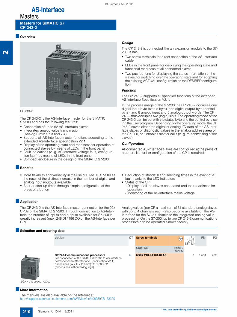
6GK7 243-2AX01-0XA0
CP 243-2 communications processors } 6GK7 243-2AX01-0XA0 1 1 unit 42CFor connection of the SIMATIC S7-200 to AS-Interface;corresponds to AS-Interface Specification V2.1;dimensions (W x H x D / mm): 71 x 80 x 62 (dimensions without fixing lugs)
IC10N_122011.book Seite 10 Donnerstag, 2. Februar 2012 4:57 16
© Siemens AG 2012

AS-InterfaceMasters
2/11Siemens IC 10 N · 12/2011
Masters for SIMATIC S7CP 343-2P, CP 343-2
2
■ Overview
CP 343-2P / CP 343-2
The CP 343-2P is the AS-Interface master for the SIMATIC S7-300 and the ET 200M distributed I/O station, with user-friendly parameterizing options.
The CP 343-2 is the basic version of the same module.
The CP 343-2P / CP 343-2 has the following features:• Connection of up to 62 AS-Interface slaves • Integrated analog value transmission (all analog profiles)• Supports all AS-Interface master functions according to the
AS-Interface Specification V3.0• Status displays of operating states and indication of the read-
iness for operation of connected slaves by means of LEDs in the front panel
• Fault indications (e. g. AS-Interface voltage fault, configura-tion fault) by means of LEDs in the front panel
• Compact enclosure in the design of the SIMATIC S7-300• Suitable for AS-i Power24V (product version 2 and higher /
firmware version 3.1) and standard AS-i (30 V)• Extra with the CP343-2P: Supports detailed configuration of
the AS-Interface-network with STEP 7 V5.2 and higher
Design
The CP 343-2P / CP 343-2 is connected like an I/O module to the S7-300. It has:• Two terminal connections for direct connection of the
AS-Interface cable• LEDs in the front panel for displaying the operating state and
the readiness for operation of all connected and activated slaves
• Pushbuttons for switching over the master operating state and for adopting the existing ACTUAL configuration of the AS-i slave as the DESIRED configuration
Function
The CP 343-2P / CP 343-2 supports all specified functions of the extended AS-Interface Specification V3.0.
The CP 343-2P / CP 343-2 occupies 16 bytes each in the I/O ad-dress area of the SIMATIC S7-300. The digital I/O data of the standard slaves and A slaves are saved in this area. The digital I/O data of the B slaves and the analog I/O data can be ac-cessed with the S7 system functions.
If required, master calls can be performed with the command in-terface,e. g. read/write parameters, read/write configuration.
You can find more information on the Internet athttp://support.automation.siemens.com/WW/view/en/51678777
Configuration
All connected AS-Interface slaves are configured at the press of a button. No further configuration of the CP is required.
Additional features of the CP 343-2P
The CP 343-2P also supports configuring of the AS-Interface network with STEP 7 V5.2 and higher. Specifying the AS-i config-uration in HW-Config facilitates the setting of slave parameters and documentation of the plant. Uploading the ACTUAL config-uration of an already configured AS-Interface network is also supported. The saved configuration cannot be overwritten at the press of a button and is therefore tamper-proof.
■ Benefits
• Shorter start-up times through simple configuration at the press of a button
• Construction of flexible distributed structures by use in the DP-slave ET 200M
• Provides diagnostics of the AS-Interface networks• Well suited also for complex applications thanks to connection
options for 62 slaves and integral analog value processing• Reduction of standstill and servicing times in the event of a
fault thanks to the LED indicators: - Status of the AS-Interface network- Slaves connected and their readiness for operation- Monitoring of the AS-Interface mains voltage
• Lower costs for stock keeping and spare parts because the CP can be used for the SIMATIC S7-300 as well as for the ET 200M
• Extra with the CP 343-2P: Improved plant documentation and support for service assignments thanks to a description of the AS-Interface configuration in the STEP7 project
• No need for the AS-i power supply unit with AS-i Power24V: The AS-Interface cable is supplied through an existing 24 V DC PELV power supply unit. An AS-i data decoupling module (e. g. 3RK1 901-1DE12-1AA0) is required for the decoupling, see page 2/14.
• Operation with AS-Interface power supply (see page 2/13) possible without restrictions.
IC10N_122011.book Seite 11 Donnerstag, 2. Februar 2012 4:57 16
© Siemens AG 2012

AS-InterfaceMastersMasters for SIMATIC S7CP 343-2P, CP 343-2
2/12 Siemens IC 10 N · 12/2011* You can order this quantity or a multiple thereof.
2
■ Application
The CP 343-2P / CP 343-2 is the AS-Interface master connection for the SIMATIC S7-300 and the ET 200M.
Through connection to AS-Interface it is possible to access max. 248 DI/248 DO per CP, using 62 A/B slaves with 4DI/4DO each.
With the integrated analog value processing it is easy to transmit analog signals (per CP up to 62 A/B analog slaves with a maxi-mum of two channels each or up to 31 A/B analog slaves with a maximum of 4 channels each).
The CP 343-2P is the further development of the CP 343-2 and contains its entire functionality. An existing STEP 7 user program for a CP 343-2 can thus be used without restrictions with a CP 343-2P. It is only in STEP 7 HW-Config that the two modules are configured differently, with the CP 343-2P offering additional op-tions. This is why the CP 343-2P is recommended.
■ Selection and ordering data
■ Accessories
■ More information
The manuals are also available on the Internet athttp://support.automation.siemens.com/WW/view/en/14310380/133300.
Information about AS-i Function Block Library for PCS 7 for easy connection of AS-Interface to PCS 7 see • Chapter 14 in IC 10 · 2012• Industry Mall: "Automation" ➞ "Industrial controls" ➞ "Parame-
terization, configuration and visualization for SIRIUS" ➞ "AS-Interface Function Block Library for SIMATIC PCS 7"
Version DT Order No. Price €per PU
PU(UNIT,
SET, M)
PS* PG
6GK7 343-2AH11-0XA0
CP 343-2P communications processors } 6GK7 343-2AH11-0XA0 1 1 unit 42C
For connection of SIMATIC S7-300 and ET 200M to AS-Interface;configuration of the AS-i network using the SET key or STEP 7 (V5.2 and higher);without front connector;corresponds to AS-Interface Specification V3.0;dimensions (W x H x D / mm): 40 x 125 x 120
6GK7 343-2AH01-0XA0
CP 343-2 communications processors } 6GK7 343-2AH01-0XA0 1 1 unit 42C
Basic version for connection of SIMATIC S7-300 and ET 200M to AS-InterfaceConfiguration of the AS-i network using the SET key;without front connector;corresponds to AS-Interface Specification V3.0;dimensions (W x H x D / mm): 40 x 125 x 120
Version DT Order No. Price €per PU
PU(UNIT,
SET, M)
PS* PG
Front connectors, 20-pole
• With screw terminals A 6ES7 392-1AJ00-0AA0 1 1 unit 230
• With spring-type terminals A 6ES7 392-1BJ00-0AA0 1 1 unit 230
IC10N_122011.book Seite 12 Donnerstag, 2. Februar 2012 4:57 16
© Siemens AG 2012

AS-InterfacePower Supply Units and Data Decoupling Modules
AS-Interface power supply units
2/13Siemens IC 10 N · 12/2011* You can order this quantity or a multiple thereof.
2
■ Overview
AS-Interface power supply unit for 3 A
AS-Interface power supply units feed 30 V DC into the AS-Inter-face cable and supply the AS-Interface components. They in-clude power-optimized data decoupling for the separation of communication signals and control supply voltage. As the result, AS-Interface is able to convey both data and power along a sin-gle line. The power supply units are resistant to overloads and short circuits.
Dimensions
AS-Interface power supply units have compact dimensions in widths of 50 / 70 / 120 mm. No distances from other devices need to be observed when mounting the power supply units.
Features• Higher rating: The power supply units deliver currents of 2.6 to
8 A.• Integrated data decoupling: As the result, AS-Interface is able
to convey both data and power along a single line.• Integrated ground-fault detection: The power supply units per-
form the reliable detection and signaling of ground faults ac-cording to IEC 60204-1. The AS-Interface voltage can be dis-connected automatically in the event of a ground fault.
• Integrated overload detection: An output overload is detected and reported over a diagnostics LED.
• Diagnostics memory: Any ground faults or overloads on the output side are stored in a diagnostics memory until the de-vice is reset.
• Remote reset and remote signaling: Using relay contacts, a ground fault can be signaled and evaluated by a central con-troller and/or indicator light.
• Diagnostics LEDs: Three different LEDs indicate the status of the AS-Interface power supply locally at the power supply unit.
• Ultra-wide input range / two-phase connection: The ultra-wide input range of 120 to 500 V of the 8 A version means that the supply units can be used in virtually any network worldwide. In addition, this version dispenses with the need for an N con-ductor as the device can be connected directly between 2 phases of a network.
• Operation with 24 V DC: The 3 A power supply unit is also available as a variant with a 24 V DC input. This power supply unit is suitable for use in battery-powered systems or in sys-tems with UPS (uninterruptible power supply).
• Removable terminal blocks with spring-type connections: For easy exchanging of devices, each power supply unit has three removable terminal blocks: for the input side, for the out-put side and for Signal/Reset connections.
■ Benefits• Complete solution for supplying AS-Interface networks while
making full use of the maximum possible cable length of 100 m or 200 m (with an extension plug) per AS-i Segment
• Only AS-i masters and AS-i slaves need to be connected to the AS-Interface cable in order to operate AS-Interface
• Compact, space-saving dimensions• Reliable power supply even for large numbers of AS-Interface
modules with a high power requirement• Integrated ground-fault and overload detection saves the
need for additional components and enhances safety
• Fast fault detection and reduced downtimes thanks to diag-nostics memory, remote signaling and remote reset
• Reduced downtimes as the result of removable terminal blocks which enable the fast exchanging of devices
• Ultra-wide input range of the 8 A version permits single-phase and two-phase operation and saves the need for an N con-ductor
• Can be used world-wide thanks to for example UL/CSA ap-proval (UL 508)
• With the 2.6 A version the output power is restricted to max. 100 W for use in NEC Class 2 circuits
■ Selection and ordering data
Version DT PU (UNIT,SET, M)
PS* PG
Order No. Price €per PU
3RX9 501-0BA00
3RX9 503-0BA00
AS-Interface power supply units, IP20
• AS-i single output 30 V DC
• With integrated ground-fault detection
• With the 2.6 A version the output power is restricted to max. 100 W (for use in NEC Class 2 circuits)
• Dimensions: Width: 50 mm (3 A / 2.6 A); 70 mm (5 A), 120 mm (8 A); Height: 125 mm; Depth: 125 mm
Output current Input voltage Spring-type terminals
2.6 A / max. 100 W 120 / 230 V AC (selectable) } 3RX9 501-2BA00 1 1 unit 42C
3 A 120 / 230 V AC (selectable) } 3RX9 501-0BA00 1 1 unit 42C
3 A 24 V DC } 3RX9 501-1BA00 1 1 unit 42C
5 A 120 / 230 V AC (selectable) } 3RX9 502-0BA00 1 1 unit 42C
8 A 120/ 230 ... 500 V AC(selectable)
} 3RX9 503-0BA00 1 1 unit 42C
IC10N_122011.book Seite 13 Donnerstag, 2. Februar 2012 4:57 16
© Siemens AG 2012

AS-InterfacePower Supply Units and Data Decoupling Modules
S22.5 data decoupling modules
2/14 Siemens IC 10 N · 12/2011
2
■ Overview
AS-Interface S22.5 double data decoupling modulesLeft: screw terminal version, Right: spring-type terminal version
With the aid of the S22.5 data decoupling module, the AS-Inter-face network can also be supplied with 24 V DC or 30 V DC from a standard power supply unit and the transmission of data and power can be realized along one cable. The combination of data decoupling modules and standard power supply units is therefore a cost-efficient alternative to the service-proven AS-Interface power supply units. The quality of the data signals and the reliable operation of the AS-i network are not negatively affected as the result.
Features of the S22.5 data decoupling module• Degree of protection IP20• Narrow design: 22.5 mm wide• Version with screw or spring-type terminals• Versions for single and double data decoupling• Supply of several AS-i networks with a single power supply
unit• Operation with 24 V DC or 30 V DC, grounded or non-
grounded• Adjustable current limiting up to 2 x 4 A• Integrated ground-fault detection with fault storage• Diagnostics LEDs and signaling contacts• Reset by button or remote reset
Ground-fault detection
The integrated ground-fault detection works with a grounded and non-grounded supply: The connection of negative pole and ground (upstream from the data decoupling module) customary with 24 V DC power supplies is permitted. A ground fault to the negative or positive pole on the AS-Interface network (down-stream from the data decoupling module) is detected and stored as a fault and will be signaled using LEDs and a relay contact.
■ Benefits• Compatible expansion of the AS-Interface system• An existing standard power supply unit with 24 V DC or 30 V
DC can be used for supplying AS-i networks• The AS-Interface system can also be used in tightly budgeted
applications because no AS-Interface power supply unit needs to be purchased
• Applications benefit in addition from the advantages of a modern bus system: - High level of standardization- Additional diagnostics and maintenance information- Faster commissioning
• Easy and cost-efficient construction of single and multiple net-works is possible
■ Application
The AS-Interface data decoupling module is designed for AS-In-terface networks with 30 V supply or 24 V supply (AS-Interface Power24V). Operation of an AS-i network with the data decoupling module and a 30 V DC standard power supply unit is technically equiv-alent to the use of an AS-Interface power supply unit and offers the service-proven features of AS-Interface for all applications.AS-Interface Power24V uses a 24 V DC power supply unit in conjunction with a data decoupling module and is particularly suitable for • Compact machines using AS-Interface
input/output modules • Applications in the control cabinet for AS-Interface integration
of SIRIUS Innovation contactors and compact feeders (3RT2 contactors through 3RA27 function modules or 3RA6 compact feeders through AS-i 3RA69 add-on modules)
When using the double data decoupling module or additional data decoupling modules, several AS-Interface networks can be operated with a single power supply unit. This results in an ad-ditional cost advantage.
Note:
The length of an AS-i Power24V network is restricted to 50 m in order to limit the voltage drop along the cable.
AS-i masters, AS-i slaves and the sensors and actuators sup-plied through the AS-i cable must be designed for the reduced voltage. Sensors and actuators for the standard voltage range of 10 to 30 V can be supplied with sufficient voltage.
The power supply units must comply with the PELV Standard (Protective Extra Low Voltage) and have a residual ripple of < 250 mVpp. We recommend power supply units from the SITOP range, see chapter 15 "Transformers and Power Supplies" in IC 10 · 2012.
IC10N_122011.book Seite 14 Donnerstag, 2. Februar 2012 4:57 16
© Siemens AG 2012
AS-InterfacePower Supply Units and Data Decoupling Modules
S22.5 data decoupling modules
2/15Siemens IC 10 N · 12/2011* You can order this quantity or a multiple thereof.
2
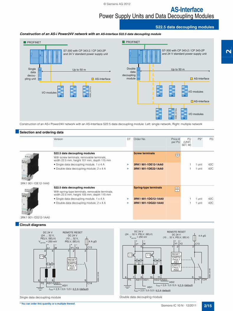
Construction of an AS-i Power24V network with an AS-Interface S22.5 data decoupling module
Construction of an AS-i Power24V network with an AS-Interface S22.5 data decoupling module: Left: single network, Right: multiple network
■ Selection and ordering data
■ Circuit diagrams
Single data decoupling module Double data decoupling module
Version DT Order No. Price €per PU
PU(UNIT,
SET, M)
PS* PG
3RK1 901-1DE12-1AA0
S22.5 data decoupling modules
With screw terminals, removable terminals, width 22.5 mm, height 101 mm, depth 115 mm
Screw terminals
• Single data decoupling module, 1 x 4 A } 3RK1 901-1DE12-1AA0 1 1 unit 42C
• Double data decoupling module, 2 x 4 A } 3RK1 901-1DE22-1AA0 1 1 unit 42C
3RK1 901-1DG12-1AA0
S22.5 data decoupling modules
With spring-type terminals, removable terminals, width 22.5 mm, height 105 mm, depth 115 mm
Spring-type terminals
• Single data decoupling module, 1 x 4 A } 3RK1 901-1DG12-1AA0 1 1 unit 42C
• Double data decoupling module, 2 x 4 A } 3RK1 901-1DG22-1AA0 1 1 unit 42C
I/O modules
I/O modules
Up to 50 mDouble data
decoupling module
S7-300 with CP 343-2 / CP 343-2Pand 24 V standard power supply unit
AS-Interface
AS-Interface
PROFINET
NS
B0_
0219
2a
I/O modules
Up to 50 mSingledata
decou-pling unit
S7-300 with CP 343-2 / CP 343-2Pand 24 V standard power supply unit
AS-Interface
PROFINET
NS
B0_
0219
1a
IC10N_122011.book Seite 15 Donnerstag, 2. Februar 2012 4:57 16
© Siemens AG 2012

AS-InterfacePower Supply Units and Data Decoupling ModulesData decoupling modules for S7-1200DCM 1271 data decoupling module
2/16 Siemens IC 10 N · 12/2011
2
■ Overview
DCM 1271 data decoupling module for SIMATIC S7-1200
Using the DCM 1271 data decoupling unit, the AS-Interface net-work can also be supplied with 24 V DC or 30 V DC from a stan-dard power supply unit and the transmission of data and power can be realized along one cable.The DCM 1271 data decoupling unit has the same enclosure de-sign as the S7-1200 unit and is therefore ideal for combining with the CM 1243-2 AS-i master.
Features of the DCM 1271 data decoupling unit• Design: S7-1200, 30 mm wide, degree of protection IP 20• Detachable terminals (included in delivery)• Single data decoupling• Supply of several AS-i networks with a single power supply
unit• Operation with 24 V DC or 30 V DC, grounded or non-
grounded• Current limiting at 4 A• Integrated ground-fault detection • Diagnostic LEDs for ground faults and overloads• Signaling contact for ground-fault detection
Ground-fault detection
The integrated ground-fault detection works with a grounded and non-grounded supply: The connection of negative pole and ground (upstream from the data decoupling module) customary with 24 V DC power supplies is permitted. A ground connection against minus or plus pole on the AS Interface network (behind the data decoupling unit) is identified and reported via LED and a contact.
■ Benefits
• An existing standard power supply unit with 24 V DC or 30 V DC can be used for supplying AS-i networks
• The AS-Interface system can also be used in tightly budgeted applications because no AS-Interface power supply unit needs to be purchased
• Applications benefit in addition from the advantages of a mod-ern bus system:- High level of standardization- Additional diagnostics and maintenance information- Faster commissioning
■ Application
The AS-Interface data decoupling module is designed for AS-In-terface networks with 30 V supply or 24 V supply (AS-Interface Power24V).
Operation of an AS-i network with the data decoupling module and a 30 V DC standard power supply unit is technically equiv-alent to the use of an AS-Interface power supply unit and offers the service-proven features of AS-Interface for all applications.
AS-Interface Power24V uses a 24 V DC power supply unit in conjunction with a data decoupling module and is particularly suitable for• Compact machines using AS Interface input/output modules• Applications in the control cabinet for AS-Interface integration
of SIRIUS Innovation contactors and compact feeders (3RT2 contactors through 3RA27 function modules or 3RA6 compact feeders through AS-i 3RA69 add-on modules)
Note:
The length of an AS-i Power24V network is restricted to 50 m in order to limit the voltage drop along the cable.
AS-i masters, AS-i slaves and the sensors and actuators sup-plied through the AS-i cable must be designed for the reduced voltage. Sensors and actuators for the standard voltage range of 10 to 30 V can be supplied with sufficient voltage.
The power supply units must comply with the PELV Standard (Protective Extra Low Voltage) and have a residual ripple of < 250 mVpp. We recommend power supply units from the SITOP range, see chapter 15 "Transformers and Power Supplies" in IC 10 · 2012.
Please also continue to observe the requirements specified in the section "Extension of AS-i Power24V" for implementation of AS-i Power24V, see page 2/7.
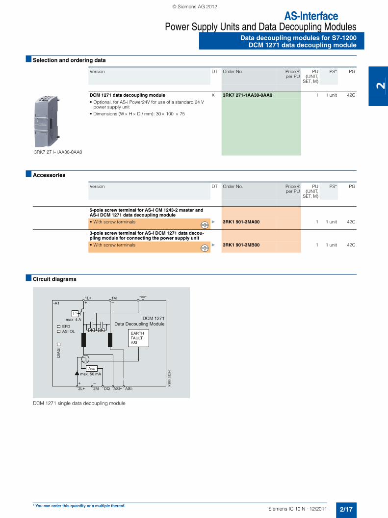
Structure of an AS-i Power24V network with AS Interface DCM 1271 data decoupling module
I/O modules
Up to 50 m
S7-1200 with DCM 1271, CM 1243-2and 24 V standard power supply unit
AS-Interface
PROFINETN
SB
0_02
245
IC10N_122011.book Seite 16 Donnerstag, 2. Februar 2012 4:57 16
© Siemens AG 2012
AS-InterfacePower Supply Units and Data Decoupling Modules
Data decoupling modules for S7-1200DCM 1271 data decoupling module
2/17Siemens IC 10 N · 12/2011* You can order this quantity or a multiple thereof.
2
■ Selection and ordering data
■ Accessories
■ Circuit diagrams
DCM 1271 single data decoupling module
Version DT Order No. Price €per PU
PU(UNIT,
SET, M)
PS* PG
3RK7 271-1AA30-0AA0
DCM 1271 data decoupling module X 3RK7 271-1AA30-0AA0 1 1 unit 42C
• Optional, for AS-i Power24V for use of a standard 24 V power supply unit
• Dimensions (W × H × D / mm): 30 × 100 × 75
Version DT Order No. Price €per PU
PU(UNIT,
SET, M)
PS* PG
5-pole screw terminal for AS-i CM 1243-2 master and AS-i DCM 1271 data decoupling module
• With screw terminals } 3RK1 901-3MA00 1 1 unit 42C
3-pole screw terminal for AS-i DCM 1271 data decou-pling module for connecting the power supply unit
• With screw terminals } 3RK1 901-3MB00 1 1 unit 42C
NS
B0_
0224
4
EARTHFAULTASI
-A11L+
2L+ 2M DQ ASI+ ASI-
EFD
max. 4 A
max. 50 mAmax
ASI OL
DIA
G
+
+
1M
DCM 1271Data Decoupling Module
IC10N_122011.book Seite 17 Donnerstag, 2. Februar 2012 4:57 16
© Siemens AG 2012

AS-InterfacePower Supply Units and Data Decoupling Modules
Notes
2/18 Siemens IC 10 N · 12/2011
2
IC10N_122011.book Seite 18 Donnerstag, 2. Februar 2012 4:57 16
© Siemens AG 2012

CatalogsIndustry Automation, Drive Technologies and Low-Voltage Power Distribution
Further information can be obtained from our branch offices listedin the appendix or at www.siemens.com/automation/partner
Interactive Catalog on DVD Catalogfor Industry Automation, Drive Technologies and Low Voltage Distribution
CA 01
Drive SystemsVariable-Speed DrivesSINAMICS G130 Drive Converter Chassis Units SINAMICS G150 Drive Converter Cabinet Units
D 11
SINAMICS GM150, SINAMICS SM150 Medium-Voltage Converters
D 12
SINAMICS S120 Chassis Format Units and Cabinet Modules SINAMICS S150 Converter Cabinet Units
D 21.3
SINAMICS DCM Converter Units D 23.1SINAMICS and Motors for Single-Axis Drives D 31
Three-phase Induction Motors• H-compact• H-compact PLUS
D 84.1
Asynchronous Motors Standardline D 86.1Synchronous Motors with Permanent-Magnet Technology, HT-direct
D 86.2
DC Motors DA 12SIMOREG DC MASTER 6RA70 Digital Chassis Converters
DA 21.1
SIMOREG K 6RA22 Analog Chassis Converters DA 21.2PDF: SIMOREG DC MASTER 6RM70 Digital Converter
Cabinet UnitsDA 22
SIMOVERT PM Modular Converter Systems DA 45SIEMOSYN Motors DA 48MICROMASTER 420/430/440 Inverters DA 51.2MICROMASTER 411/COMBIMASTER 411 DA 51.3SIMOVERT MASTERDRIVES Vector Control DA 65.10SIMOVERT MASTERDRIVES Motion Control DA 65.11Synchronous and asynchronous servomotors for SIMOVERT MASTERDRIVES
DA 65.3
SIMODRIVE 611 universal and POSMO DA 65.4SIMOTION, SINAMICS S120 and Motors for Production Machines
PM 21
SINUMERIK, SIMODRIVE and Motors for Machine Tools
NC 60
SINUMERIK, SINAMICS S120 and Motors for Machine Tools
NC 61
Low-Voltage Three-Phase-MotorsIEC Squirrel-Cage Motors D 81.1MOTOX Geared Motors D 87.1
Mechanical Driving MachinesFLENDER Standard Couplings MD 10.1FLENDER SIG Standard industrial gear unit MD 30.1
Low-Voltage Power Distribution and Electrical Installation Technology
SENTRON Protection, Switching, Measuring and Monitoring Devices
LV 10.1
SIVACON · ALPHA Switchboards and Distribution Systems
LV 10.2
SIVACON 8PS Busbar Trunking Systems LV 70GAMMA Building Control ET G1PDF: DELTA Switches and Socket Outlets ET D1
PDF: These catalogs are only available as pdf files.
Motion Control Catalog
SINAMICS and Motors for Single-Axis Drives D 31SINUMERIK & SIMODRIVE Automation Systems for Machine Tools
NC 60
SINUMERIK & SINAMICS Equipment for Machine Tools
NC 61
SINUMERIK 828D BASIC T/BASIC M, SINAMICS S120 Combi and 1FK7/1PH8 motors
NC 82
SIMOTION, SINAMICS S120 and Motors for Production Machines
PM 21
Drive and Control Components for Cranes CR 1
Power Supply and System CablingPower supply SITOP KT 10.1System cabling SIMATIC TOP connect KT 10.2
Process Instrumentation and AnalyticsField Instruments for Process Automation FI 01SIREC Recorders and Accessories MP 20SIPART, Controllers and Software MP 31Products for Weighing Technology WT 10PDF: Process Analytical Instruments PA 01PDF: Process Analytics,
Components for the System IntegrationPA 11
Safety IntegratedSafety Technology for Factory Automation SI 10
SIMATIC HMI/PC-based AutomationHuman Machine Interface Systems/PC-based Automation
ST 80/ ST PC
SIMATIC IdentIndustrial Identification Systems ID 10
SIMATIC Industrial Automation SystemsProducts for Totally Integrated Automation and Micro Automation
ST 70
SIMATIC PCS 7 Process Control System ST PCS 7Add-ons for the SIMATIC PCS 7 Process Control System
ST PCS 7.1
PDF: Migration solutions with the SIMATIC PCS 7 Process Control System
ST PCS 7.2
SIMATIC NETIndustrial Communication IK PI
SINVERT PhotovoltaicsInverters and Components for Photovoltaic Installations RE 10
SIRIUS Industrial Controls SIRIUS Industrial Controls IC 10SIRIUS Industrial Controls (selected content from catalog IC 10)
IC 90
SITRAIN Information und Training ITC
System SolutionsApplications and Products for Industry are part of the interactive catalog CA 01
Download-Center
PDF versions of the catalogs are available on the Internet at:www.siemens.com/automation/infocenter
IC10N_122011.book Seite 2 Donnerstag, 2. Februar 2012 4:57 16
© Siemens AG 2012

The information provided in this catalog contains descriptions orcharacteristics of performance which in case of actual use do notalways apply as described or which may change as a result of furtherdevelopment of the products. An obligation to providethe respective characteristics shall only exist if expressly agreed inthe terms of contract. Availability and technical specifications aresubject to change without notice.All product designations may be trademarks or product namesof Siemens AG or supplier companies whose use by thirdparties for their own purposes could violate the rights ofthe owners.www.siemens.com/automation
Subject to change without prior noticePDF only: (E86060-K1010-A131-A1-7600)MP.R3.CP.0000.00.2.24 KG 0112 22 En © Siemens AG 2012
Siemens AGIndustry SectorControl Components and Systems EngineeringPostfach 235590713 FÜRTHGERMANY
Get more information
Control Components and Systems Engineering:www.siemens.com/sirius
ic10N_asi-master_s7-1200_umschlag_en.indd 2ic10N_asi-master_s7-1200_umschlag_en.indd 2 25.01.2012 14:28:1325.01.2012 14:28:13
© Siemens AG 2012