Embed Size (px)
Citation preview
1
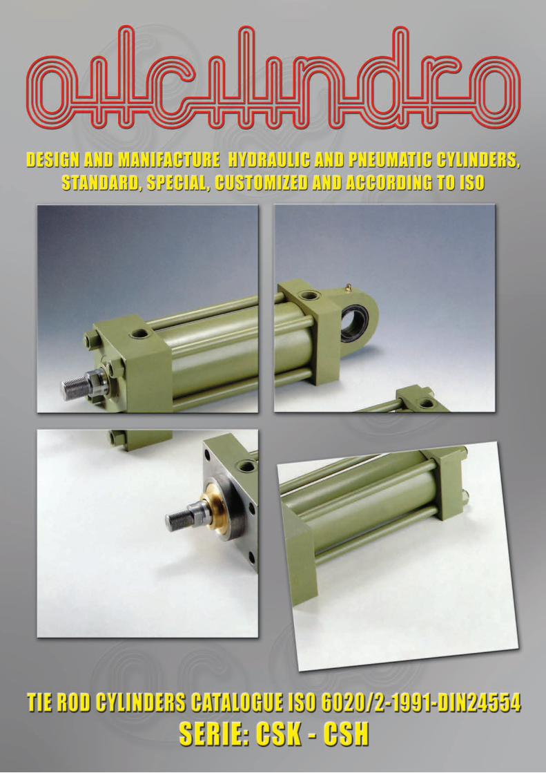
HYDRAULIC HYDRAULIC CYLINDERSCYLINDERS
ACCORDING TO ISO 6020/2-1991-DIN24554CATALOGUE 42.16
SQUARE HEADS WITH TIE-RODS
WITH COUNTERFLANGESFOR LONG STROKES
CSKCSKCSHCSH
• Double acting with or without cushioning• Nominal pressure: 160 bar• Max overload: 210 bar• Max pressure: 250 bar• Operating temperature: –20° C +85° C
• Several mounting options• Several rod options• Single or double rod-strokes up to 5000 mm• Bore available from Ø 25 a Ø 200 mm• Rods available from Ø 12 a Ø 140 mm
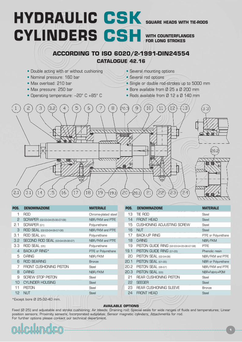
AVAILABLE OPTIONSFixed (Ø 25) and adjustable end stroke cushioning; Air bleeds; Draining rod; Special seals for wide ranges of fluids and temperatures; Linearposition sensors; Proximity sensors; Incorporated subplates; Sensor magnetic cylinders; Attachments for rod.For further options please contact our technical department.
POS. DENOMINAZIONE MATERIALE POS. DENOMINAZIONE MATERIALE
1 ROD Chrome-plated steel
2 SCRAPER (G2-G3-G4-G5-G6-G7-G8) NBR/FKM and PTFE
2.1 SCRAPER (G1) Polyurethane
3 ROD SEAL (G2-G3-G4-G6-G7-G8) NBR/FKM and PTFE
3.1 ROD SEAL (G1) Polyurethane
3.2 SECOND ROD SEAL (G3-G4-G5-G6-G7) NBR/FKM and PTFE
3.3 ROD SEAL (G5) Polyurethane
4 BACK-UP RING* PTFE or Polyurethane
5 O-RING NBR/FKM
6 ROD BEARING Bronze
7 FRONT CUSHIONING PISTON Steel
8 O-RING NBR/FKM
9 SCREW STOP PISTON Steel
10 CYLINDER HOUSING Steel
11 PISTON Steel
12 NUT Steel
13 TIE ROD Steel
14 FRONT HEAD Steel
15 CUSHIONING ADJUSTING SCREW Steel
16 NUT Steel
17 BACK-UP RING PTFE or Polyurethane
18 O-RING NBR/FKM
19 PISTON GUIDE RING (G2-G3-G4-G5-G6-G7-G8) PTFE
19.1 PISTON GUIDE RING (G1-G5) Phenolic resin
20 PISTON SEAL (G2-G4-G8) NBR/FKM and PTFE
20.1 PISTON SEAL (G1-G5) NBR or Polyurethane
20.2 PISTON SEAL (G6-G7) NBR/FKM and PTFE
20.3 PISTON SEAL (G3) NBR+Fabric+POM
21 REAR CUSHIONING PISTON Steel
22 SEEGER Steel
23 REAR CUSHIONING SLEEVE Bronze
24 FRONT HEAD Steel
*Except bore Ø 25-32-40 mm.
SEZ. SEZ. 11.. PRESENTATION
2
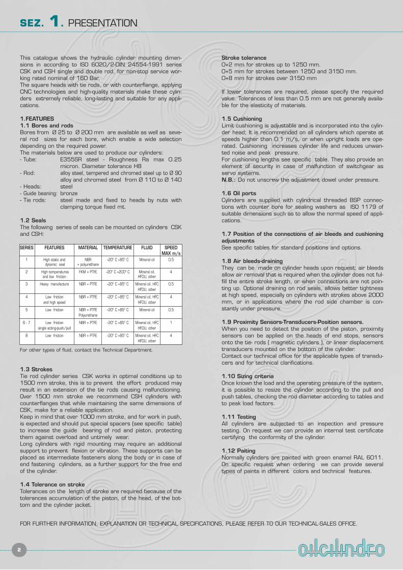
This catalogue shows the hydraulic cylinder mounting dimen-sions in according to ISO 6020/2-DIN 24554-1991 seriesCSK and CSH single and double rod, for non-stop service wor-king rated nominal of 160 Bar.The square heads with tie rods, or with counterflange, applyingCNC technologies and high-quality materials make these cylin-ders extremely reliable, long-lasting and suitable for any appli-cations.
1.FEATURES1.1 Bores and rodsBores from Ø 25 to Ø 200 mm are available as well as seve-ral rod sizes for each bore, which enable a wide selectiondepending on the required power.The materials below are used to produce our cylinders:- Tube: E355SR steel - Roughness Ra max 0.25
micron. Diameter tolerance H8- Rod: alloy steel, tempered and chromed steel up to Ø 90
alloy and chromed steel from Ø 110 to Ø 140- Heads: steel- Guide beaning: bronze- Tie rods: steel made and fixed to heads by nuts with
clamping torque fixed mt.
1.2 SealsThe following series of seals can be mounted on cylinders CSKand CSH:
1.3 StrokesTie rod cylinder series CSK works in optimal conditions up to1500 mm stroke, this is to prevent the effort produced mayresult in an extension of the tie rods causing malfunctioning.Over 1500 mm stroke we recommend CSH cylinders withcounterflanges that while maintaining the same dimensions ofCSK, make for a reliable application.Keep in mind that over 1000 mm stroke, and for work in push,is expected and should put special spacers (see specific table)to increase the guide bearing of rod and piston, protectingthem against overload and untimely wear.Long cylinders with rigid mounting may require an additionalsupport to prevent flexion or vibration. These supports can beplaced as intermediate fasteners along the body or in case ofend fastening cylinders, as a further support for the free endof the cylinder.
1.4 Tolerance on strokeTolerances on the length of stroke are required because of thetolerances accumulation of the piston, of the head, of the bot-tom and the cylinder jacket.
Stroke tolerance0+2 mm for strokes up to 1250 mm.0+5 mm for strokes between 1250 and 3150 mm.0+8 mm for strokes over 3150 mm
If lower tolerances are required, please specify the requiredvalue. Tolerances of less than 0.5 mm are not generally availa-ble for the elasticity of materials.
1.5 CushioningLimit cushioning is adjustable and is incorporated into the cylin-der head; It is recommended on all cylinders which operate atspeeds higher than 0.1 m/s, or when upright loads are ope-rated. Cushioning increases cylinder life and reduces unwan-ted noise and peak pressure. For cushioning lengths see specific table. They also provide anelement of security in case of malfunction of switchgear asservo systems.N.B.: Do not unscrew the adjustment dowel under pressure.
1.6 Oil portsCylinders are supplied with cylindrical threaded BSP connec-tions with counter bore for sealing washers as ISO 1179 ofsuitable dimensions such as to allow the normal speed of appli-cations.
1.7 Position of the connections of air bleeds and cushioningadjustmentsSee specific tables for standard positions and options.
1.8 Air bleeds-drainingThey can be made on cylinder heads upon request; air bleedsallow air removal that is required when the cylinder does not ful-fill the entire stroke length, or when connections are not poin-ting up. Optional draining on rod seals, allows better tightnessat high speed, especially on cylinders with strokes above 2000mm, or in applications where the rod side chamber is con-stantly under pressure.
1.9 Proximity Sensors-Transducers-Position sensors.When you need to detect the position of the piston, proximitysensors can be applied on the heads of end stops, sensorsonto the tie- rods ( magnetic cylinders ), or linear displacementtransducers mounted on the bottom of the cylinder.Contact our technical office for the applicable types of transdu-cers and for technical clarifications.
1.10 Sizing criteriaOnce known the load and the operating pressure of the system,it is possible to resize the cylinder according to the pull andpush tables, checking the rod diameter according to tables andto peak load factors.
1.11 TestingAll cylinders are subjected to an inspection and pressuretesting. On request we can provide an internal test certificatecertifying the conformity of the cylinder.
1.12 PaitingNormally cylinders are painted with green enamel RAL 6011.On specific request when ordering we can provide severaltypes of paints in different colors and technical features.
SERIES FEATURES MATERIAL TEMPERATURE FLUID SPEEDMAX m/s
1 High static and NBR –20° C +85° C Mineral oil 0,5dynamic seal + polyurethane
2 High temperatures FKM + PTFE –20° C +200° C Mineral oil, 4and low friction HFDU, other
3 Heavy manufacture NBR + PTFE –20° C +85° C Mineral oil, HFC 0,5HFDU, other
4 Low friction NBR + PTFE –20° C +85° C Mineral oil, HFC 4and high speed HFDU, other
5 Low friction NBR + PTFE –20° C +85° C Mineral oil 0,5Polyurethane
6 - 7 Low friction NBR + PTFE –20° C +85° C Mineral oil, HFC 1single acting-push/pull HFDU, other
8 Low friction NBR + PTFE –20° C +85° C Mineral oil, HFC 4HFDU, other
FOR FURTHER INFORMATION, EXPLANATION OR TECHNICAL SPECIFICATIONS, PLEASE REFER TO OUR TECHNICAL-SALES OFFICE.
For other types of fluid, contact the Technical Department.
SEZ. SEZ. 22.. MANUFACTURE TYPOLOGY
3
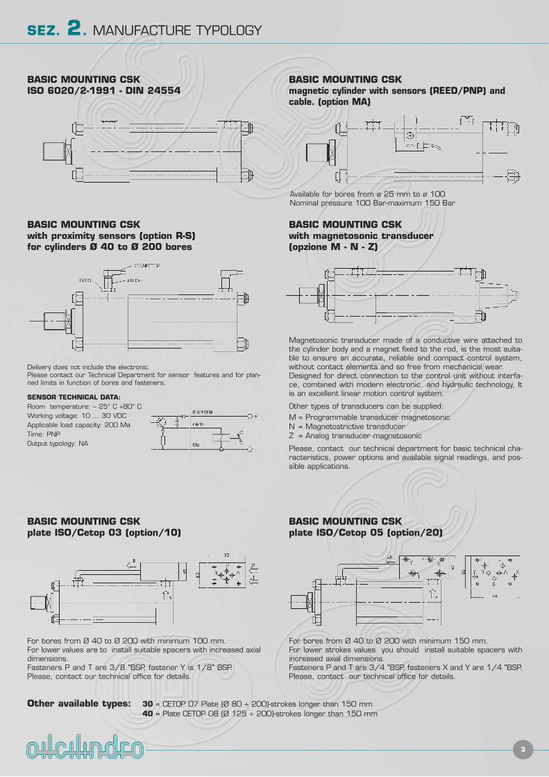
BASIC MOUNTING CSKISO 6020/2-1991 - DIN 24554
BASIC MOUNTING CSKmagnetic cylinder with sensors (REED/PNP) andcable. (option MA)
Available for bores from ø 25 mm to ø 100Nominal pressure 100 Bar-maximum 150 Bar
BASIC MOUNTING CSKplate ISO/Cetop 05 (option/20)
BASIC MOUNTING CSKplate ISO/Cetop 03 (option/10)
For bores from Ø 40 to Ø 200 with minimum 150 mm.For lower strokes values you should install suitable spacers withincreased axial dimensions.Fasteners P and T are 3/4 "BSP, fasteners X and Y are 1/4 "BSP. Please, contact our technical office for details.
For bores from Ø 40 to Ø 200 with minimum 100 mm.For lower values are to install suitable spacers with increased axialdimensions.Fasteners P and T are 3/8 "BSP, fastener Y is 1/8" BSP.Please, contact our technical office for details.
BASIC MOUNTING CSKwith proximity sensors (option R-S)for cylinders Ø 40 to Ø 200 bores
BASIC MOUNTING CSKwith magnetosonic transducer(opzione M - N - Z)
Magnetosonic transducer made of a conductive wire attached tothe cylinder body and a magnet fixed to the rod, is the most suita-ble to ensure an accurate, reliable and compact control system,without contact elements and so free from mechanical wear.Designed for direct connection to the control unit without interfa-ce, combined with modern electronic and hydraulic technology, Itis an excellent linear motion control system.
Other types of transducers can be supplied:M = Programmable transducer magnetosonicN = Magnetostrictive transducerZ = Analog transducer magnetosonic
Please, contact our technical department for basic technical cha-racteristics, power options and available signal readings, and pos-sible applications.
Delivery does not include the electronic.Please contact our Technical Department for sensor features and for plan-ned limits in function of bores and fasteners.
SENSOR TECHNICAL DATA:Room temperature: – 25° C +80° CWorking voltage: 10 ... 30 VDCApplicable load capacity: 200 MaTime: PNPOutput typology: NA
Other available types: 30 = CETOP 07 Plate (Ø 80 ÷ 200)-strokes longer than 150 mm40 = Plate CETOP 08 (Ø 125 ÷ 200)-strokes longer than 150 mm
4
SEZ. SEZ. 33.. SYMBOLOGY, SCHEMATIZATION AND BASIC FORMULAS
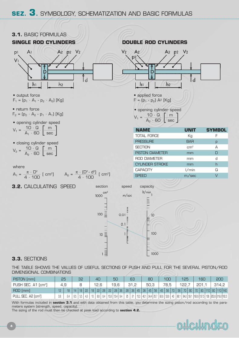
• output force F1 = (p1 · A1 - p2 · A2) [Kg]
• return forceF2 = (p2 · A2 - p1 · A1) [Kg]
• opening cylinder speed
V1 = [ ]10 · QA1 · 60
msec
• closing cylinder speed
V2 = [ ]10 · QA2 · 60
msec
where
A1 = [ cm2]π · D2
4 · 100A2 = [ cm2]π · (D2 - d2)
4 · 100
• applied forceF = (p1 - p2) A2 [Kg]
• opening cylinder speed
V1 = [ ]10 · QA2 · 60
msec
NAME UNIT SYMBOLTOTAL FORCE Kg F
PRESSURE BAR p
SECTION cm2 A
PISTON DIAMETER mm D
ROD DIAMETER mm d
CYLINDER STROKE mm h
CAPACITY l/min Q
SPEED m/sec V
SINGLE ROD CYLINDERS DOUBLE ROD CYLINDERS
3.1. BASIC FORMULAS
3.2. CALCULATING SPEED
3.3. SECTIONS
THE TABLE SHOWS THE VALUES OF USEFUL SECTIONS OF PUSH AND PULL FOR THE SEVERAL PISTON/RODDIMENSIONAL COMBINATIONS
With formulas included in section 3.1 and with data obtained from this table, you determine the sizing piston/rod according to the para-meters system (strength, speed, capacity).The sizing of the rod must then be checked at peak load according to section 4.2.
PISTON [mm] 25 32 40 50 63 80 100 125 160 200PUSH SEC. A1 [cm2] 4,9 8 12,6 19,6 31,2 50,3 78,5 122,7 201,1 314,2ROD [mm] 12 18 14 18 22 18 22 28 22 28 36 28 36 45 36 45 56 45 56 70 56 70 90 70 90 110 90 110 140
PULL SEC. A2 [cm2] 3,8 2,4 6,5 5,5 4,2 10 8,8 6,4 15,8 13,4 9,4 25 21 15,3 40,1 34,4 25,7 62,6 53,9 40 98,1 84,2 59,1 162,6 137,5 106 250,6 219,2 160,3
section speed capacity
5
SEZ. SEZ. 44.. VERIFICATION AT PEAK LOAD
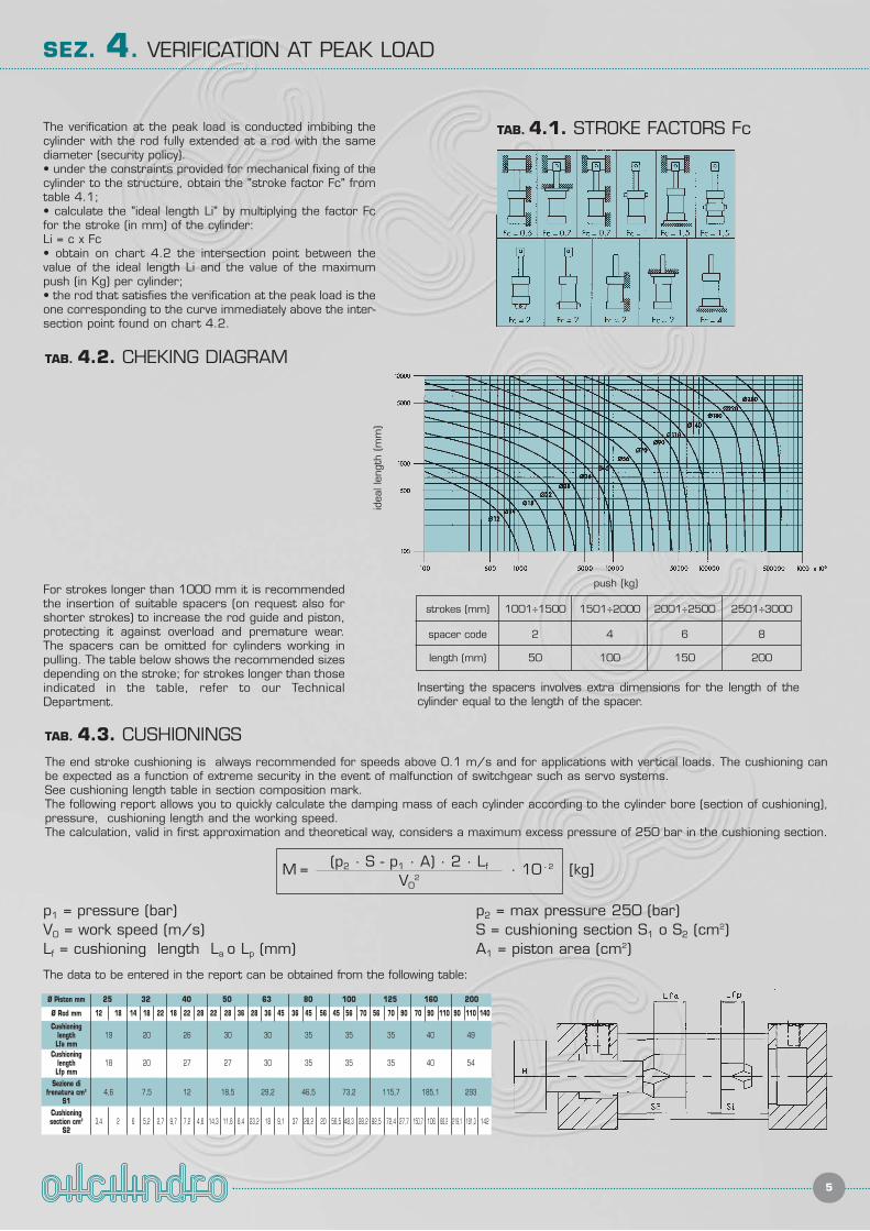
The verification at the peak load is conducted imbibing thecylinder with the rod fully extended at a rod with the samediameter (security policy).• under the constraints provided for mechanical fixing of thecylinder to the structure, obtain the "stroke factor Fc" fromtable 4.1; • calculate the "ideal length Li" by multiplying the factor Fcfor the stroke (in mm) of the cylinder:Li = c x Fc• obtain on chart 4.2 the intersection point between thevalue of the ideal length Li and the value of the maximumpush (in Kg) per cylinder; • the rod that satisfies the verification at the peak load is theone corresponding to the curve immediately above the inter-section point found on chart 4.2.
The end stroke cushioning is always recommended for speeds above 0.1 m/s and for applications with vertical loads. The cushioning canbe expected as a function of extreme security in the event of malfunction of switchgear such as servo systems. See cushioning length table in section composition mark. The following report allows you to quickly calculate the damping mass of each cylinder according to the cylinder bore (section of cushioning),pressure, cushioning length and the working speed.The calculation, valid in first approximation and theoretical way, considers a maximum excess pressure of 250 bar in the cushioning section.
TAB. 4.2. CHEKING DIAGRAM
TAB. 4.3. CUSHIONINGS
TAB. 4.1. STROKE FACTORS Fc
For strokes longer than 1000 mm it is recommendedthe insertion of suitable spacers (on request also forshorter strokes) to increase the rod guide and piston,protecting it against overload and premature wear.The spacers can be omitted for cylinders working inpulling. The table below shows the recommended sizesdepending on the stroke; for strokes longer than thoseindicated in the table, refer to our TechnicalDepartment.
Inserting the spacers involves extra dimensions for the length of thecylinder equal to the length of the spacer.
The data to be entered in the report can be obtained from the following table:
strokes (mm) 1001÷1500 1501÷2000 2001÷2500 2501÷3000
spacer code 2 4 6 8
length (mm) 50 100 150 200
M = [kg]· 10 - 2(p2 · S - p1 · A) · 2 · Lf
V02
p1 = pressure (bar)V0 = work speed (m/s)Lf = cushioning length La o Lp (mm)
p2 = max pressure 250 (bar)S = cushioning section S1 o S2 (cm2)A1 = piston area (cm2)
Ø Piston mm 25 32 40 50 63 80 100 125 160 200
Ø Rod mm 12 18 14 18 22 18 22 28 22 28 36 28 36 45 36 45 56 45 56 70 56 70 90 70 90 110 90 110 140
Cushioninglength 19 20 26 30 30 35 35 35 40 49Lfa mm
Cushioninglength 18 20 27 27 30 35 35 35 40 54Lfp mm
Sezione difrenatura cm2 4,6 7,5 12 18,5 29,2 46,5 73,2 115,7 185,1 293
S1Cushioningsection cm2 3,4 2 6 5,2 2,7 9,7 7,2 4,6 14,3 11,6 6,4 23,2 18 9,1 37 28,2 20 56,5 48,3 28,2 92,5 72,4 27,7 150,7 106 68,2 219,1 181,3 142
S2
idea
l len
gth (m
m)
push (kg)
SEZ. SEZ. 55.. COMPOSITION CODE
6
CYLINDER CODE SERIES CSK - CSH
SPARE SEALS CODE
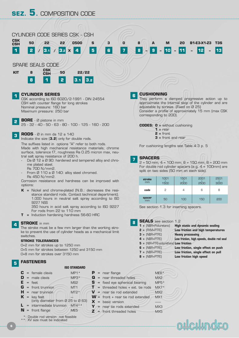
1 CYLINDER SERIESCSK according to ISO 6020/2-1991 - DIN 24554CSH with counter flange for long strokesNominal pressure: 160 barMaximum pressure: 250 bar
2 BORE - Ø pistone in mm25 - 32 - 40 - 50 - 63 - 80 - 100 - 125 - 160 - 200
3 RODS - Ø in mm da 12 a 140Indicate the size (3.2) only for double rods.
The suffixes listed in options "A" refer to both rods.Made with high mechanical resistance materials; chromesurface, tolerance f7, roughness Ra 0.25 micron max, neu-tral salt spray resistance of 200 h.- Da Ø 12 a Ø 90: hardened and tempered alloy and chro-
me plated steel.Rs 700 N/mm2.
- From Ø 110 a Ø 140: alloy steel chromed.Rs 450 N/mm2.
Corrosion resistance and hardness can be improved withoptions:
K = Nickel and chrome-plated (N.B.: decreases the resi-stance standard rods. Contact technical department).1.000 hours in neutral salt spray according to ISO9227 NSS350 hours in acid salt spray according to ISO 9227For rods from 22 to 110 mm
T = Induction hardening hardness 56-60 HRC
4 STROKE in mmThe stroke must be a few mm larger than the working stro-ke to prevent the use of cylinder heads as a mechanical limitswitches.STROKE TOLERANCES0+2 mm for strokes up to 1250 mm0+5 mm for strokes between 1250 and 3150 mm0+8 mm for strokes over 3150 mm
5 FASTENERSISO STANDARD
C = female clevis MP1*D = male clevis MP3*E = feet MS2G = front trunnion MT1H = rear trunnion MT2*K = key feet ---
(only diameter from Ø 25 to Ø 63)L = intermediate trunnion MT4**N = front flange ME5
*: Double rod version not feasible**: XV size must be indicated
7 SPACERS2 = 50 mm; 4 = 100 mm; 6 = 150 mm; 8 = 200 mmFor double rod cylinder spacers (e.g. 4 = 100mm) aresplit on two sides (50 mm on each side).
8 SEALS see section 1.21 = (NBR+Poliuretano) High static and dynamic sealing2 = (FKM+PTFE) Low friction and high temperatures3 = (NBR+PTFE) Heavy processing4 = (NBR+PTFE) Low friction, high speeds, double rod seal5 = (NBR+PTFE+polyurethane) Low friction6 = (NBR+PTFE) Low friction, single effect on push7 = (NBR+PTFE) Low friction, single effect on pull8 = (NBR+PTFE) Low friction high speed
6 CUSHIONINGThey perform a damped progressive action up toapproximate the internal stop of the cylinder and areadjustable by screws. (Fixed on Ø 25)Consider a profile of approximately 15 mm (max CSKcorresponding to 200).
CODES: 0 = without cushioning1 = rear2 = front3 = front and rear
For cushioning lengths see Table 4.3 p. 5
1 2 3.1/
CSKCSH 50 22 22 0500 S 3 0 8
3.2 4 5 6 7 8
A
9
M
10
T3S
12
20
11/ –X
8 1
KIT 8CSKCSH 50 22/22
2 3.1 3.2
stroke 1001 1501 2001 2501mm ÷ ÷ ÷ ÷
1500 2000 2500 3000
code 2 4 6 8
spacermm 50 100 150 200
B1-E3-X1-Z3
13
P = rear flange ME6*Q = rear threaded holes MX2S = fixed eye sphenical bearing MP5*T = threaded holes + ext. tie rods MX7*V = rear tie rod extended MX2W = front + rear tie rod extended MX1X = basic version -------Y = rear tie rods extended MX3Z = front threaded holes MX5
See section 1.3 for inserting spacers.
–– – –
SEZ. SEZ. 55.. CODE COMPOSITION
7
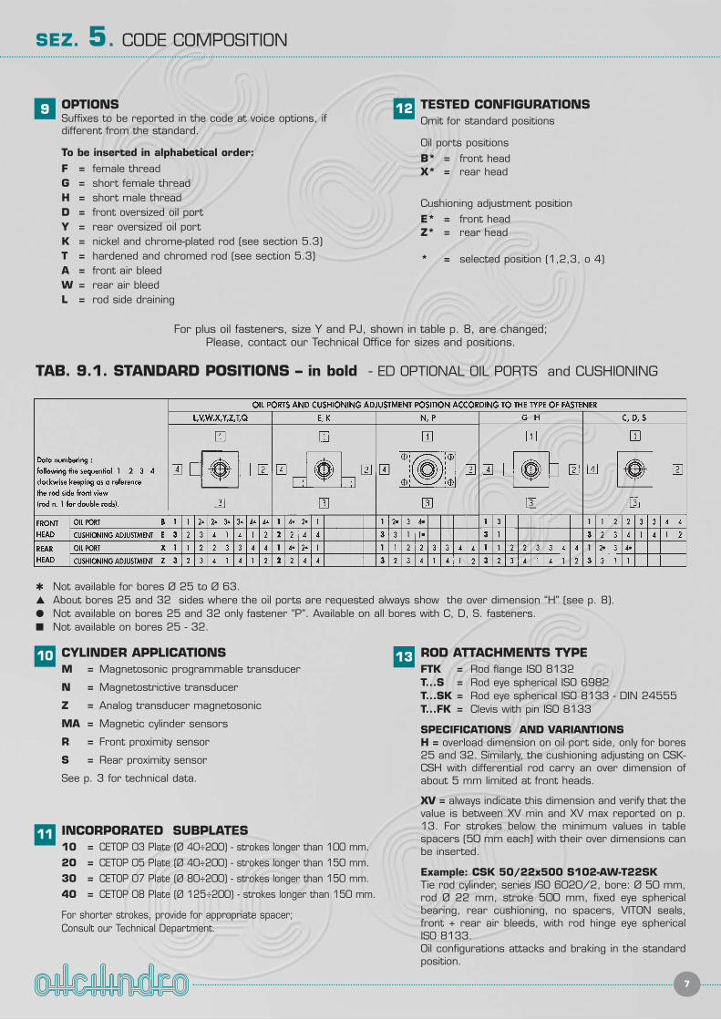
9 OPTIONSSuffixes to be reported in the code at voice options, ifdifferent from the standard.
To be inserted in alphabetical order:
F = female threadG = short female threadH = short male threadD = front oversized oil portY = rear oversized oil portK = nickel and chrome-plated rod (see section 5.3)T = hardened and chromed rod (see section 5.3)A = front air bleedW = rear air bleedL = rod side draining
CYLINDER APPLICATIONSM = Magnetosonic programmable transducer
N = Magnetostrictive transducer
Z = Analog transducer magnetosonic
MA = Magnetic cylinder sensors
R = Front proximity sensor
S = Rear proximity sensor
See p. 3 for technical data.
13 ROD ATTACHMENTS TYPEFTK = Rod flange ISO 8132T...S = Rod eye spherical ISO 6982T...SK = Rod eye spherical ISO 8133 - DIN 24555T...FK = Clevis with pin ISO 8133
SPECIFICATIONS AND VARIANTIONSH = overload dimension on oil port side, only for bores25 and 32. Similarly, the cushioning adjusting on CSK-CSH with differential rod carry an over dimension ofabout 5 mm limited at front heads.
XV = always indicate this dimension and verify that thevalue is between XV min and XV max reported on p.13. For strokes below the minimum values in tablespacers (50 mm each) with their over dimensions canbe inserted.
Example: CSK 50/22x500 S102-AW-T22SKTie rod cylinder, series ISO 6020/2, bore: Ø 50 mm,rod Ø 22 mm, stroke 500 mm, fixed eye sphericalbearing, rear cushioning, no spacers, VITON seals,front + rear air bleeds, with rod hinge eye sphericalISO 8133.Oil configurations attacks and braking in the standardposition.
11 INCORPORATED SUBPLATES10 = CETOP 03 Plate (Ø 40÷200) - strokes longer than 100 mm.
20 = CETOP 05 Plate (Ø 40÷200) - strokes longer than 150 mm.
30 = CETOP 07 Plate (Ø 80÷200) - strokes longer than 150 mm.
40 = CETOP 08 Plate (Ø 125÷200) - strokes longer than 150 mm.
For shorter strokes, provide for appropriate spacer; Consult our Technical Department.
TAB. 9.1. STANDARD POSITIONS – in bold - ED OPTIONAL OIL PORTS and CUSHIONING
For plus oil fasteners, size Y and PJ, shown in table p. 8, are changed;Please, contact our Technical Office for sizes and positions.
� Not available for bores Ø 25 to Ø 63.� About bores 25 and 32 sides where the oil ports are requested always show the over dimension “H” (see p. 8).� Not available on bores 25 and 32 only fastener “P”. Available on all bores with C, D, S. fasteners.� Not available on bores 25 - 32.
12 TESTED CONFIGURATIONSOmit for standard positions
Oil ports positions
B* = front headX* = rear head
Cushioning adjustment position
E* = front headZ* = rear head
* = selected position (1,2,3, o 4)
10
CYLINDERS SERIES CSK
8
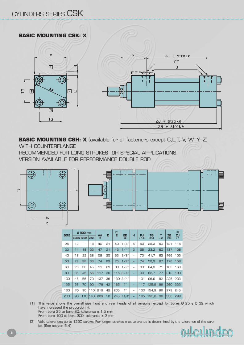
BASIC MOUNTING CSK: X
BASIC MOUNTING CSH: X (available for all fasteners except C,L,T, V, W, Y, Z)WITH COUNTERFLANGERECOMMENDED FOR LONG STROKES OR SPECIAL APPLICATIONSVERSION AVAILABLE FOR PERFORMANCE DOUBLE ROD
BOREØ ROD mm
AA D E EE H PJ TG Y ZB ZJSTANDARD INTERM. DIFFER. RIF. 6g ± 1,5 js13 ± 2 max ± 1
25 12 – 18 40 21 40 1/4” 5 53 28,3 50 121 114
32 14 18 22 47 21 45 1/4” 5 56 33,2 60 137 128
40 18 22 28 59 25 63 3/8” – 73 41,7 62 166 153
50 22 28 36 74 29 75 1/2” – 74 52,3 67 176 159
63 28 36 45 91 29 90 1/2” – 80 64,3 71 185 168
80 36 45 56 117 36 115 3/4” – 93 82,7 77 212 190
100 45 56 70 137 36 130 3/4” – 101 96,9 82 225 203
125 56 70 90 178 42 165 1” – 117 125,9 86 260 232
160 70 90 110 219 42 205 1” – 130 154,9 86 279 245
200 90 110 140 269 52 245 1 1/4” – 165 190,2 98 336 299
(1) This value shows the overall size front and rear heads of all versions, except for bores Ø 25 e Ø 32 which have increased the proportion H.From bore 25 to bore 80, tolerance ± 1,5 mmFrom bore 100 to bore 200, tolerance ± 2 mm
(3) Valid tolerances up to 1250 stroke; For longer strokes max tolerance is determined by the tolerance of the stro-ke. (See section 5.4)
(1) (3)
CYLINDERS SERIES CSK
9
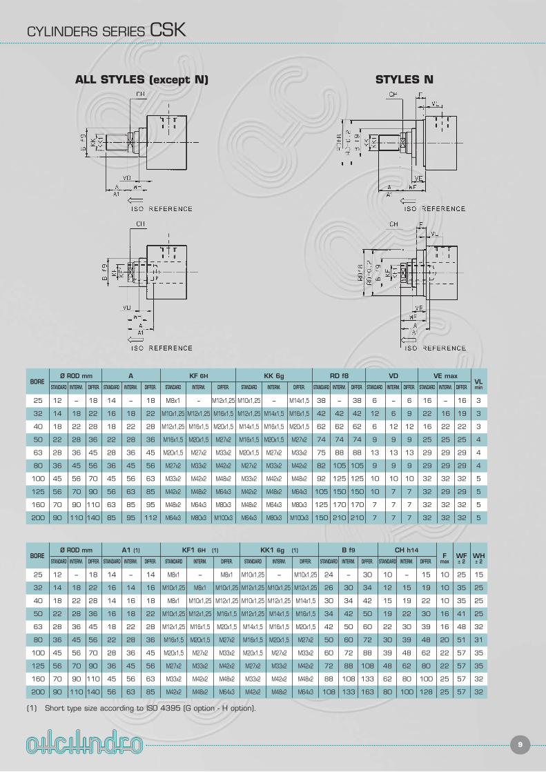
ALL STYLES (except N) STYLES N
A KF 6H KK 6g RD f8 VD VE maxVL
STANDARD INTERM. DIFFER. STANDARD INTERM. DIFFER. STANDARD INTERM. DIFFER. STANDARD INTERM. DIFFER. STANDARD INTERM. DIFFER. STANDARD INTERM. DIFFER. min
14 – 18 M8x1 – M12x1,25 M10x1,25 – M14x1,5 38 – 38 6 – 6 16 – 16 3
16 18 22 M10x1,25 M12x1,25 M16x1,5 M12x1,25 M14x1,5 M16x1,5 42 42 42 12 6 9 22 16 19 3
18 22 28 M12x1,25 M16x1,5 M20x1,5 M14x1,5 M16x1,5 M20x1,5 62 62 62 6 12 12 16 22 22 3
22 28 36 M16x1,5 M20x1,5 M27x2 M16x1,5 M20x1,5 M27x2 74 74 74 9 9 9 25 25 25 4
28 36 45 M20x1,5 M27x2 M33x2 M20x1,5 M27x2 M33x2 75 88 88 13 13 13 29 29 29 4
36 45 56 M27x2 M33x2 M42x2 M27x2 M33x2 M42x2 82 105 105 9 9 9 29 29 29 4
45 56 63 M33x2 M42x2 M48x2 M33x2 M42x2 M48x2 92 125 125 10 10 10 32 32 32 5
56 63 85 M42x2 M48x2 M64x3 M42x2 M48x2 M64x3 105 150 150 10 7 7 32 29 29 5
63 85 95 M48x2 M64x3 M80x3 M48x2 M64x3 M80x3 125 170 170 7 7 7 32 32 32 5
85 95 112 M64x3 M80x3 M100x3 M64x3 M80x3 M100x3 150 210 210 7 7 7 32 32 32 5
BOREØ ROD mm
STANDARD INTERM. DIFFER.
25 12 – 18
32 14 18 22
40 18 22 28
50 22 28 36
63 28 36 45
80 36 45 56
100 45 56 70
125 56 70 90
160 70 90 110
200 90 110 140
A1 (1) KF1 6H (1) KK1 6g (1) B f9 CH h14F WF WH
STANDARD INTERM. DIFFER. STANDARD INTERM. DIFFER. STANDARD INTERM. DIFFER. STANDARD INTERM. DIFFER. STANDARD INTERM. DIFFER. max ± 2 ± 2
14 – 14 M8x1 – M8x1 M10x1,25 – M10x1,25 24 – 30 10 – 15 10 25 15
16 14 16 M10x1,25 M8x1 M10x1,25 M12x1,25 M10x1,25 M12x1,25 26 30 34 12 15 19 10 35 25
14 16 18 M8x1 M10x1,25 M12x1,25 M10x1,25 M12x1,25 M14x1,5 30 34 42 15 19 22 10 35 25
16 18 22 M10x1,25 M12x1,25 M16x1,5 M12x1,25 M14x1,5 M16x1,5 34 42 50 19 22 30 16 41 25
18 22 28 M12x1,25 M16x1,5 M20x1,5 M14x1,5 M16x1,5 M20x1,5 42 50 60 22 30 39 16 48 32
22 28 36 M16x1,5 M20x1,5 M27x2 M16x1,5 M20x1,5 M27x2 50 60 72 30 39 48 20 51 31
28 36 45 M20x1,5 M27x2 M33x2 M20x1,5 M27x2 M33x2 60 72 88 39 48 62 22 57 35
36 45 56 M27x2 M33x2 M42x2 M27x2 M33x2 M42x2 72 88 108 48 62 80 22 57 35
45 56 63 M33x2 M42x2 M48x2 M33x2 M42x2 M48x2 88 108 133 62 80 100 25 57 32
56 63 85 M42x2 M48x2 M64x3 M42x2 M48x2 M64x3 108 133 163 80 100 128 25 57 32
BOREØ ROD mm
STANDARD INTERM. DIFFER.
25 12 – 18
32 14 18 22
40 18 22 28
50 22 28 36
63 28 36 45
80 36 45 56
100 45 56 70
125 56 70 90
160 70 90 110
200 90 110 140
(1) Short type size according to ISO 4395 (G option - H option).
CYLINDERS SERIES CSK
10
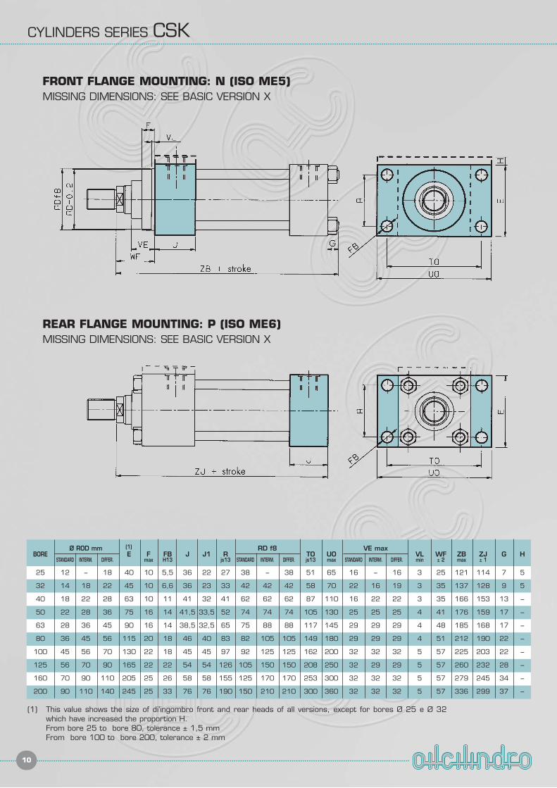
BOREØ ROD mm
E F FB J J1 RRD f8
TO UOVE max
VL WF ZB ZJ G HSTANDARD INTERM. DIFFER. max H13 js13 STANDARD INTERM. DIFFER. js13 max STANDARD INTERM. DIFFER. min ± 2 max ± 1
25 12 – 18 40 10 5,5 36 22 27 38 – 38 51 65 16 – 16 3 25 121 114 7 5
32 14 18 22 45 10 6,6 36 23 33 42 42 42 58 70 22 16 19 3 35 137 128 9 5
40 18 22 28 63 10 11 41 32 41 62 62 62 87 110 16 22 22 3 35 166 153 13 --
50 22 28 36 75 16 14 41,5 33,5 52 74 74 74 105 130 25 25 25 4 41 176 159 17 --
63 28 36 45 90 16 14 38,5 32,5 65 75 88 88 117 145 29 29 29 4 48 185 168 17 --
80 36 45 56 115 20 18 46 40 83 82 105 105 149 180 29 29 29 4 51 212 190 22 --
100 45 56 70 130 22 18 45 45 97 92 125 125 162 200 32 32 32 5 57 225 203 22 --
125 56 70 90 165 22 22 54 54 126 105 150 150 208 250 32 29 29 5 57 260 232 28 --
160 70 90 110 205 25 26 58 58 155 125 170 170 253 300 32 32 32 5 57 279 245 34 --
200 90 110 140 245 25 33 76 76 190 150 210 210 300 360 32 32 32 5 57 336 299 37 --
FRONT FLANGE MOUNTING: N (ISO ME5)MISSING DIMENSIONS: SEE BASIC VERSION X
(1)
REAR FLANGE MOUNTING: P (ISO ME6)MISSING DIMENSIONS: SEE BASIC VERSION X
(1) This value shows the size of di'ingombro front and rear heads of all versions, except for bores Ø 25 e Ø 32 which have increased the proportion H.From bore 25 to bore 80, tolerance ± 1,5 mmFrom bore 100 to bore 200, tolerance ± 2 mm
CYLINDERS SERIES CSK
11
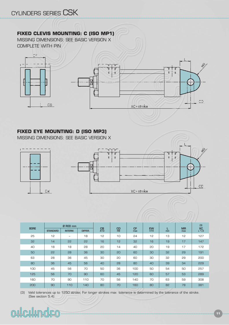
BOREØ ROD mm
CB CD CF EW L MR XCSTANDARD INTERM. DIFFER. A13 H9 max h14 min max ± 1,5
25 12 – 18 12 10 24 12 13 12 127
32 14 22 22 16 12 32 16 19 17 147
40 18 18 28 20 14 40 20 19 17 172
50 22 28 36 30 20 60 30 32 29 191
63 28 36 45 30 20 60 30 32 29 200
80 36 45 56 40 28 80 40 39 34 229
100 45 56 70 50 36 100 50 54 50 257
125 56 70 90 60 45 120 60 57 53 289
160 70 90 110 70 56 140 70 63 59 308
200 90 110 140 80 70 160 80 82 78 381
FIXED CLEVIS MOUNTING: C (ISO MP1)MISSING DIMENSIONS: SEE BASIC VERSION XCOMPLETE WITH PIN
FIXED EYE MOUNTING: D (ISO MP3)MISSING DIMENSIONS: SEE BASIC VERSION X
(3) Valid tolerances up to 1250 stroke; For longer strokes max tolerance is determined by the tolerance of the stroke.(See section 5.4)
(3)
CYLINDERS SERIES CSK
12
FIXED EYE WITH SPHERICAL BEARING MOUTING: S (ISO MP5)MISSING DIMENSIONS: SEE BASIC VERSION X
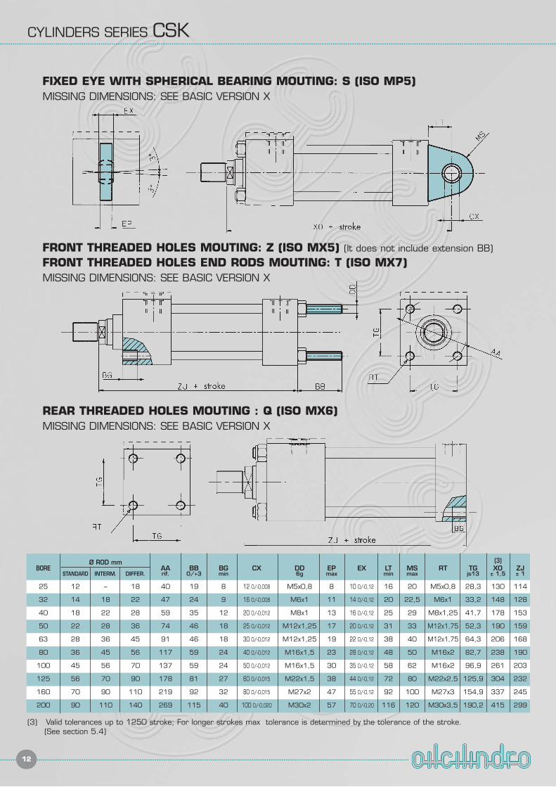
BOREØ ROD mm
AA BB BG CX DD EP EX LT MS RT TG XO ZJSTANDARD INTERM. DIFFER. rif. 0/+3 min 6g max min max js13 ± 1,5 ± 1
25 12 – 18 40 19 8 12 0/-0,008 M5x0,8 8 10 0/-0,12 16 20 M5x0,8 28,3 130 114
32 14 18 22 47 24 9 16 0/-0,008 M6x1 11 14 0/-0,12 20 22,5 M6x1 33,2 148 128
40 18 22 28 59 35 12 20 0/-0,012 M8x1 13 16 0/-0,12 25 29 M8x1,25 41,7 178 153
50 22 28 36 74 46 18 25 0/-0,012 M12x1,25 17 20 0/-0,12 31 33 M12x1,75 52,3 190 159
63 28 36 45 91 46 18 30 0/-0,012 M12x1,25 19 22 0/-0,12 38 40 M12x1,75 64,3 206 168
80 36 45 56 117 59 24 40 0/-0,012 M16x1,5 23 28 0/-0,12 48 50 M16x2 82,7 238 190
100 45 56 70 137 59 24 50 0/-0,012 M16x1,5 30 35 0/-0,12 58 62 M16x2 96,9 261 203
125 56 70 90 178 81 27 60 0/-0,015 M22x1,5 38 44 0/-0,12 72 80 M22x2,5 125,9 304 232
160 70 90 110 219 92 32 80 0/-0,015 M27x2 47 55 0/-0,12 92 100 M27x3 154,9 337 245
200 90 110 140 269 115 40 100 0/-0,020 M30x2 57 70 0/-0,20 116 120 M30x3,5 190,2 415 299
FRONT THREADED HOLES MOUTING: Z (ISO MX5) (It does not include extension BB)
FRONT THREADED HOLES END RODS MOUTING: T (ISO MX7)MISSING DIMENSIONS: SEE BASIC VERSION X
(3) Valid tolerances up to 1250 stroke; For longer strokes max tolerance is determined by the tolerance of the stroke.(See section 5.4)
REAR THREADED HOLES MOUTING : Q (ISO MX6)MISSING DIMENSIONS: SEE BASIC VERSION X
(3)
CYLINDERS SERIES CSK
13
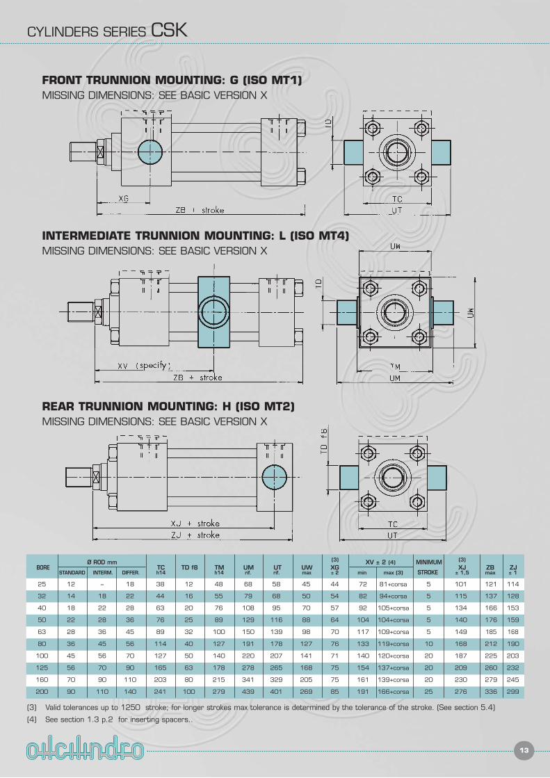
FRONT TRUNNION MOUNTING: G (ISO MT1)MISSING DIMENSIONS: SEE BASIC VERSION X
INTERMEDIATE TRUNNION MOUNTING: L (ISO MT4)MISSING DIMENSIONS: SEE BASIC VERSION X
BOREØ ROD mm
TC TD f8 TM UM UT UW XGXV ± 2 (4) MINIMUM
XJ ZB ZJSTANDARD INTERM. DIFFER. h14 h14 rif. rif. max ± 2 min max (3) STROKE ± 1,5 max ± 1
25 12 – 18 38 12 48 68 58 45 44 72 81+corsa 5 101 121 114
32 14 18 22 44 16 55 79 68 50 54 82 94+corsa 5 115 137 128
40 18 22 28 63 20 76 108 95 70 57 92 105+corsa 5 134 166 153
50 22 28 36 76 25 89 129 116 88 64 104 104+corsa 5 140 176 159
63 28 36 45 89 32 100 150 139 98 70 117 109+corsa 5 149 185 168
80 36 45 56 114 40 127 191 178 127 76 133 119+corsa 10 168 212 190
100 45 56 70 127 50 140 220 207 141 71 140 120+corsa 20 187 225 203
125 56 70 90 165 63 178 278 265 168 75 154 137+corsa 20 209 260 232
160 70 90 110 203 80 215 341 329 205 75 161 139+corsa 20 230 279 245
200 90 110 140 241 100 279 439 401 269 85 191 166+corsa 25 276 336 299
REAR TRUNNION MOUNTING: H (ISO MT2)MISSING DIMENSIONS: SEE BASIC VERSION X
(3) Valid tolerances up to 1250 stroke; for longer strokes max tolerance is determined by the tolerance of the stroke. (See section 5.4)
(4) See section 1.3 p.2 for inserting spacers..
(3) (3)
CYLINDERS SERIES CSK
14
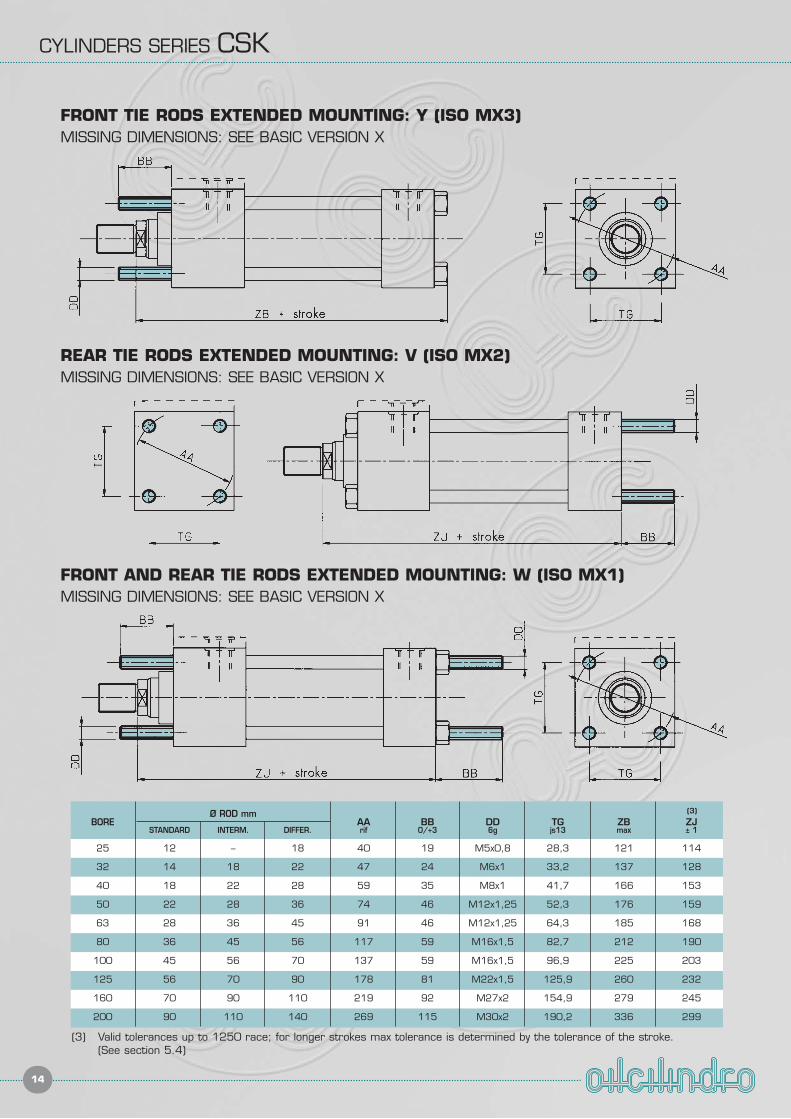
FRONT TIE RODS EXTENDED MOUNTING: Y (ISO MX3)MISSING DIMENSIONS: SEE BASIC VERSION X
FRONT AND REAR TIE RODS EXTENDED MOUNTING: W (ISO MX1)MISSING DIMENSIONS: SEE BASIC VERSION X
BOREØ ROD mm
AA BB DD TG ZB ZJSTANDARD INTERM. DIFFER. rif 0/+3 6g js13 max ± 1
25 12 – 18 40 19 M5x0,8 28,3 121 114
32 14 18 22 47 24 M6x1 33,2 137 128
40 18 22 28 59 35 M8x1 41,7 166 153
50 22 28 36 74 46 M12x1,25 52,3 176 159
63 28 36 45 91 46 M12x1,25 64,3 185 168
80 36 45 56 117 59 M16x1,5 82,7 212 190
100 45 56 70 137 59 M16x1,5 96,9 225 203
125 56 70 90 178 81 M22x1,5 125,9 260 232
160 70 90 110 219 92 M27x2 154,9 279 245
200 90 110 140 269 115 M30x2 190,2 336 299
(3) Valid tolerances up to 1250 race; for longer strokes max tolerance is determined by the tolerance of the stroke.(See section 5.4)
(3)
REAR TIE RODS EXTENDED MOUNTING: V (ISO MX2)MISSING DIMENSIONS: SEE BASIC VERSION X
CYLINDERS SERIES CSK
15
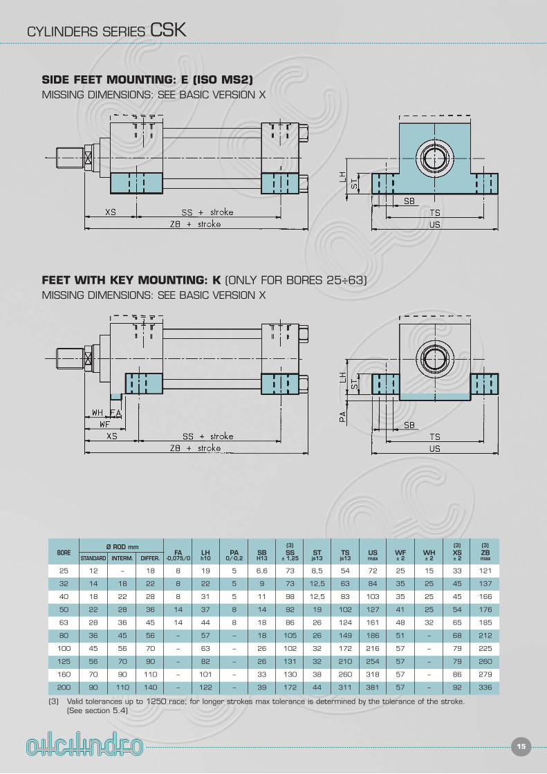
BOREØ ROD mm
FA LH PA SB SS ST TS US WF WH XS ZBSTANDARD INTERM. DIFFER. -0,075/0 h10 0/-0,2 H13 ± 1,25 js13 js13 max ± 2 ± 2 ± 2 max
25 12 – 18 8 19 5 6,6 73 8,5 54 72 25 15 33 121
32 14 18 22 8 22 5 9 73 12,5 63 84 35 25 45 137
40 18 22 28 8 31 5 11 98 12,5 83 103 35 25 45 166
50 22 28 36 14 37 8 14 92 19 102 127 41 25 54 176
63 28 36 45 14 44 8 18 86 26 124 161 48 32 65 185
80 36 45 56 – 57 – 18 105 26 149 186 51 – 68 212
100 45 56 70 – 63 – 26 102 32 172 216 57 – 79 225
125 56 70 90 – 82 – 26 131 32 210 254 57 – 79 260
160 70 90 110 – 101 – 33 130 38 260 318 57 – 86 279
200 90 110 140 – 122 – 39 172 44 311 381 57 – 92 336
(3) Valid tolerances up to 1250 race; for longer strokes max tolerance is determined by the tolerance of the stroke.(See section 5.4)
(3) (3) (3)
SIDE FEET MOUNTING: E (ISO MS2)MISSING DIMENSIONS: SEE BASIC VERSION X
FEET WITH KEY MOUNTING: K (ONLY FOR BORES 25÷63)MISSING DIMENSIONS: SEE BASIC VERSION X
16
CYLINDERS SERIES CSK
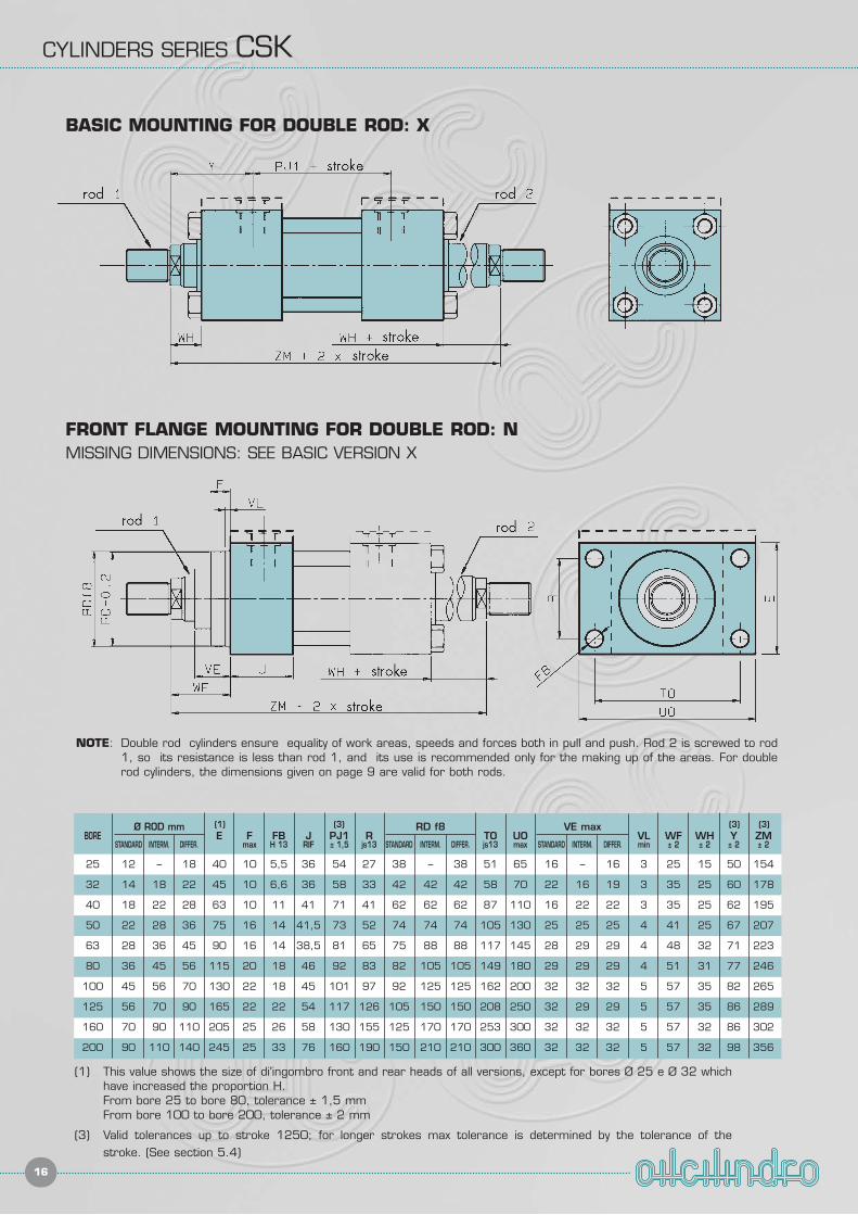
BOREØ ROD mm
E F FB J PJ1 RRD f8
TO UOVE max
VL WF WH Y ZMSTANDARD INTERM. DIFFER. max H 13 RIF ± 1,5 js13 STANDARD INTERM. DIFFER. js13 max STANDARD INTERM. DIFFER. min ± 2 ± 2 ± 2 ± 2
25 12 – 18 40 10 5,5 36 54 27 38 – 38 51 65 16 – 16 3 25 15 50 154
32 14 18 22 45 10 6,6 36 58 33 42 42 42 58 70 22 16 19 3 35 25 60 178
40 18 22 28 63 10 11 41 71 41 62 62 62 87 110 16 22 22 3 35 25 62 195
50 22 28 36 75 16 14 41,5 73 52 74 74 74 105 130 25 25 25 4 41 25 67 207
63 28 36 45 90 16 14 38,5 81 65 75 88 88 117 145 28 29 29 4 48 32 71 223
80 36 45 56 115 20 18 46 92 83 82 105 105 149 180 29 29 29 4 51 31 77 246
100 45 56 70 130 22 18 45 101 97 92 125 125 162 200 32 32 32 5 57 35 82 265
125 56 70 90 165 22 22 54 117 126 105 150 150 208 250 32 29 29 5 57 35 86 289
160 70 90 110 205 25 26 58 130 155 125 170 170 253 300 32 32 32 5 57 32 86 302
200 90 110 140 245 25 33 76 160 190 150 210 210 300 360 32 32 32 5 57 32 98 356
(1) This value shows the size of di'ingombro front and rear heads of all versions, except for bores Ø 25 e Ø 32 whichhave increased the proportion H.From bore 25 to bore 80, tolerance ± 1,5 mmFrom bore 100 to bore 200, tolerance ± 2 mm
(3) Valid tolerances up to stroke 1250; for longer strokes max tolerance is determined by the tolerance of thestroke. (See section 5.4)
(3) (3)(3)
NOTE: Double rod cylinders ensure equality of work areas, speeds and forces both in pull and push. Rod 2 is screwed to rod1, so its resistance is less than rod 1, and its use is recommended only for the making up of the areas. For doublerod cylinders, the dimensions given on page 9 are valid for both rods.
BASIC MOUNTING FOR DOUBLE ROD: X
FRONT FLANGE MOUNTING FOR DOUBLE ROD: NMISSING DIMENSIONS: SEE BASIC VERSION X
(1)
17
CYLINDERS SERIES CSK
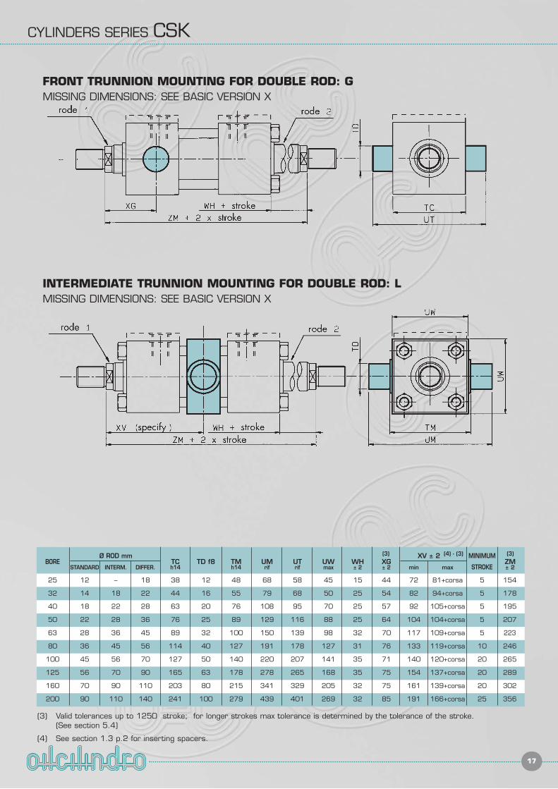
FRONT TRUNNION MOUNTING FOR DOUBLE ROD: GMISSING DIMENSIONS: SEE BASIC VERSION X
INTERMEDIATE TRUNNION MOUNTING FOR DOUBLE ROD: LMISSING DIMENSIONS: SEE BASIC VERSION X
BOREØ ROD mm
TC TD f8 TM UM UT UW WH XGXV ± 2 MINIMUM
ZMSTANDARD INTERM. DIFFER. h14 h14 rif rif max ± 2 ± 2 min max STROKE ± 2
25 12 – 18 38 12 48 68 58 45 15 44 72 81+corsa 5 154
32 14 18 22 44 16 55 79 68 50 25 54 82 94+corsa 5 178
40 18 22 28 63 20 76 108 95 70 25 57 92 105+corsa 5 195
50 22 28 36 76 25 89 129 116 88 25 64 104 104+corsa 5 207
63 28 36 45 89 32 100 150 139 98 32 70 117 109+corsa 5 223
80 36 45 56 114 40 127 191 178 127 31 76 133 119+corsa 10 246
100 45 56 70 127 50 140 220 207 141 35 71 140 120+corsa 20 265
125 56 70 90 165 63 178 278 265 168 35 75 154 137+corsa 20 289
160 70 90 110 203 80 215 341 329 205 32 75 161 139+corsa 20 302
200 90 110 140 241 100 279 439 401 269 32 85 191 166+corsa 25 356
(3) Valid tolerances up to 1250 stroke; for longer strokes max tolerance is determined by the tolerance of the stroke.(See section 5.4)
(4) See section 1.3 p.2 for inserting spacers.
(3) (3)(4) - (3)
CYLINDERS SERIES CSK
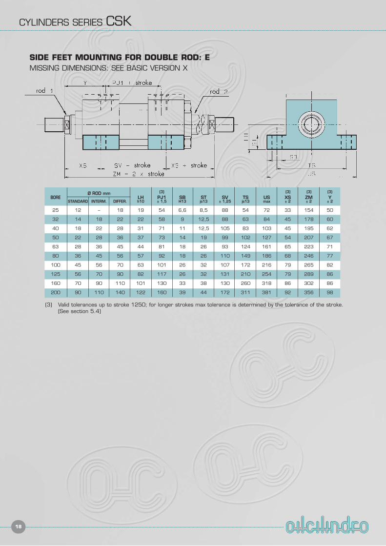
18
BOREØ ROD mm
LH PJ1 SB ST SV TS US XS ZM YSTANDARD INTERM. DIFFER. h10 ± 1,5 H13 js13 ± 1,25 js13 max ± 2 ± 2 ± 2
25 12 – 18 19 54 6,6 8,5 88 54 72 33 154 50
32 14 18 22 22 58 9 12,5 88 63 84 45 178 60
40 18 22 28 31 71 11 12,5 105 83 103 45 195 62
50 22 28 36 37 73 14 19 99 102 127 54 207 67
63 28 36 45 44 81 18 26 93 124 161 65 223 71
80 36 45 56 57 92 18 26 110 149 186 68 246 77
100 45 56 70 63 101 26 32 107 172 216 79 265 82
125 56 70 90 82 117 26 32 131 210 254 79 289 86
160 70 90 110 101 130 33 38 130 260 318 86 302 86
200 90 110 140 122 160 39 44 172 311 381 92 356 98
(3) Valid tolerances up to stroke 1250; for longer strokes max tolerance is determined by the tolerance of the stroke. (See section 5.4)
(3) (3) (3) (3)
SIDE FEET MOUNTING FOR DOUBLE ROD: EMISSING DIMENSIONS: SEE BASIC VERSION X
ATTACHMENTS FOR HYDRAULIC CYLINDERS ISO 6020/2
19
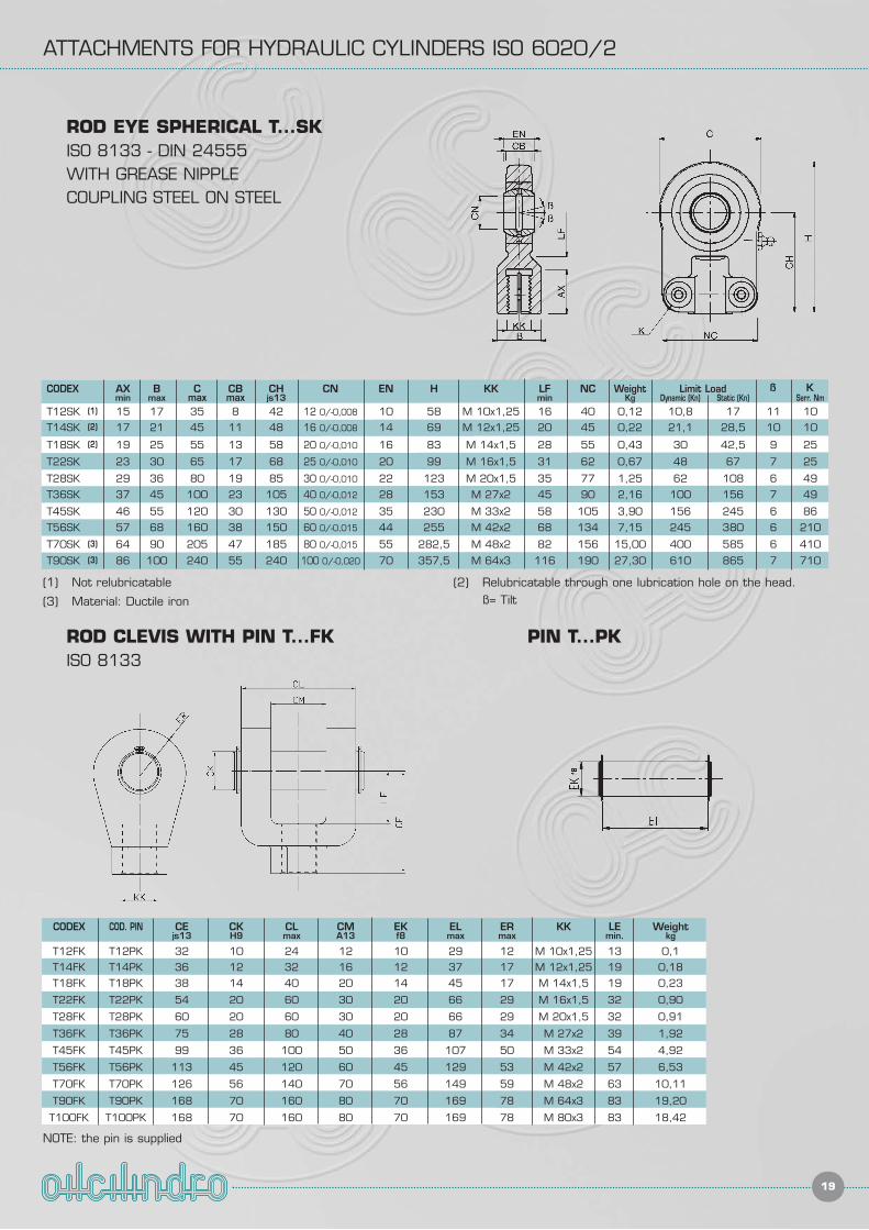
ROD CLEVIS WITH PIN T...FKISO 8133
PIN T...PK
ROD EYE SPHERICAL T...SKISO 8133 - DIN 24555WITH GREASE NIPPLECOUPLING STEEL ON STEEL
CODEX AX B C CB CH CN EN H KK LF NC Weight Limit Load ß K
min max max max js13 min Kg Dynamic (Kn) Static (Kn) Serr. Nm
T12SK 15 17 35 8 42 12 0/-0,008 10 58 M 10x1,25 16 40 0,12 10,8 17 11 10
T14SK 17 21 45 11 48 16 0/-0,008 14 69 M 12x1,25 20 45 0,22 21,1 28,5 10 10
T18SK 19 25 55 13 58 20 0/-0,010 16 83 M 14x1,5 28 55 0,43 30 42,5 9 25
T22SK 23 30 65 17 68 25 0/-0,010 20 99 M 16x1,5 31 62 0,67 48 67 7 25
T28SK 29 36 80 19 85 30 0/-0,010 22 123 M 20x1,5 35 77 1,25 62 108 6 49
T36SK 37 45 100 23 105 40 0/-0,012 28 153 M 27x2 45 90 2,16 100 156 7 49
T45SK 46 55 120 30 130 50 0/-0,012 35 230 M 33x2 58 105 3,90 156 245 6 86
T56SK 57 68 160 38 150 60 0/-0,015 44 255 M 42x2 68 134 7,15 245 380 6 210
T70SK 64 90 205 47 185 80 0/-0,015 55 282,5 M 48x2 82 156 15,00 400 585 6 410
T90SK 86 100 240 55 240 100 0/-0,020 70 357,5 M 64x3 116 190 27,30 610 865 7 710
(1)
(2)
(2)
(3)
(3)
(1) Not relubricatable
(3) Material: Ductile iron
(2) Relubricatable through one lubrication hole on the head.ß= Tilt
CODEX COD. PIN CE CK CL CM EK EL ER KK LE Weightjs13 H9 max A13 f8 max max min. kg
T12FK T12PK 32 10 24 12 10 29 12 M 10x1,25 13 0,1
T14FK T14PK 36 12 32 16 12 37 17 M 12x1,25 19 0,18
T18FK T18PK 38 14 40 20 14 45 17 M 14x1,5 19 0,23
T22FK T22PK 54 20 60 30 20 66 29 M 16x1,5 32 0,90
T28FK T28PK 60 20 60 30 20 66 29 M 20x1,5 32 0,91
T36FK T36PK 75 28 80 40 28 87 34 M 27x2 39 1,92
T45FK T45PK 99 36 100 50 36 107 50 M 33x2 54 4,92
T56FK T56PK 113 45 120 60 45 129 53 M 42x2 57 6,53
T70FK T70PK 126 56 140 70 56 149 59 M 48x2 63 10,11
T90FK T90PK 168 70 160 80 70 169 78 M 64x3 83 19,20
T100FK T100PK 168 70 160 80 70 169 78 M 80x3 83 18,42
NOTE: the pin is supplied
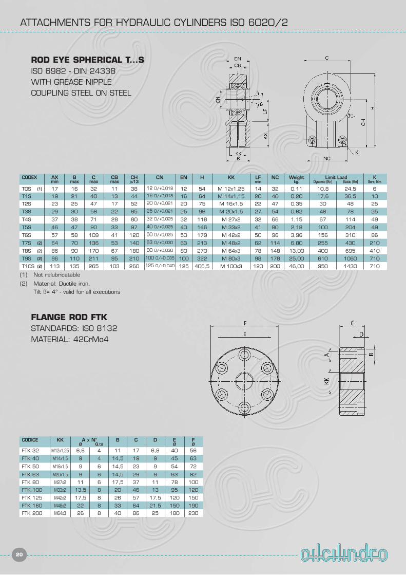
ATTACHMENTS FOR HYDRAULIC CYLINDERS ISO 6020/2
20
ROD EYE SPHERICAL T...SISO 6982 - DIN 24338WITH GREASE NIPPLECOUPLING STEEL ON STEEL
CODEX AX B C CB CH CN EN H KK LF NC Weight Limit Load Kmin max max max js13 min kg. Dynamic (Kn) Static (Kn) Serr. Nm
T0S 17 16 32 11 38 12 0/+0,018 12 54 M 12x1,25 14 32 0,11 10,8 24,5 6
T1S 19 21 40 13 44 16 0/+0,018 16 64 M 14x1,15 20 40 0,20 17,6 36,5 10
T2S 23 25 47 17 52 20 0/+0,021 20 75 M 16x1,5 22 47 0,35 30 48 25
T3S 29 30 58 22 65 25 0/+0,021 25 96 M 20x1,5 27 54 0,62 48 78 25
T4S 37 38 71 28 80 32 0/+0,025 32 118 M 27x2 32 66 1,15 67 114 49
T5S 46 47 90 33 97 40 0/+0,025 40 146 M 33x2 41 80 2,18 100 204 49
T6S 57 58 109 41 120 50 0/+0,025 50 179 M 42x2 50 96 3,96 156 310 86
T7S 64 70 136 53 140 63 0/+0,030 63 213 M 48x2 62 114 6,80 255 430 210
T8S 86 90 170 67 180 80 0/+0,030 80 270 M 64x3 78 148 13,00 400 695 410
T9S 96 110 211 95 210 100 0/+0,035 100 322 M 80x3 98 178 25,00 610 1060 710
T10S 113 135 265 103 260 125 0/+0,040 125 406,5 M 100x3 120 200 46,00 950 1430 710
(1)
(1) Not relubricatable
(2) Material: Ductile iron.Tilt ß= 4° - valid for all executions
(2)
(2)
(2)
(2)
FLANGE ROD FTKSTANDARDS: ISO 8132MATERIAL: 42CrMo4
CODICE KK A x N° B C D E FØ Q.tà Ø Ø
FTK 32 M12x1,25 6,6 4 11 17 6,8 40 56
FTK 40 M14x1,5 9 4 14,5 19 9 45 63
FTK 50 M16x1,5 9 6 14,5 23 9 54 72
FTK 63 M20x1,5 9 6 14,5 29 9 63 82
FTK 80 M27x2 11 6 17,5 37 11 78 100
FTK 100 M33x2 13,5 8 20 46 13 95 120
FTK 125 M42x2 17,5 8 26 57 17,5 120 150
FTK 160 M48x2 22 8 33 64 21,5 150 190
FTK 200 M64x3 26 8 40 86 25 180 230
ATTACHMENTS FOR HYDRAULIC CYLINDERS ISO 6020/2
21
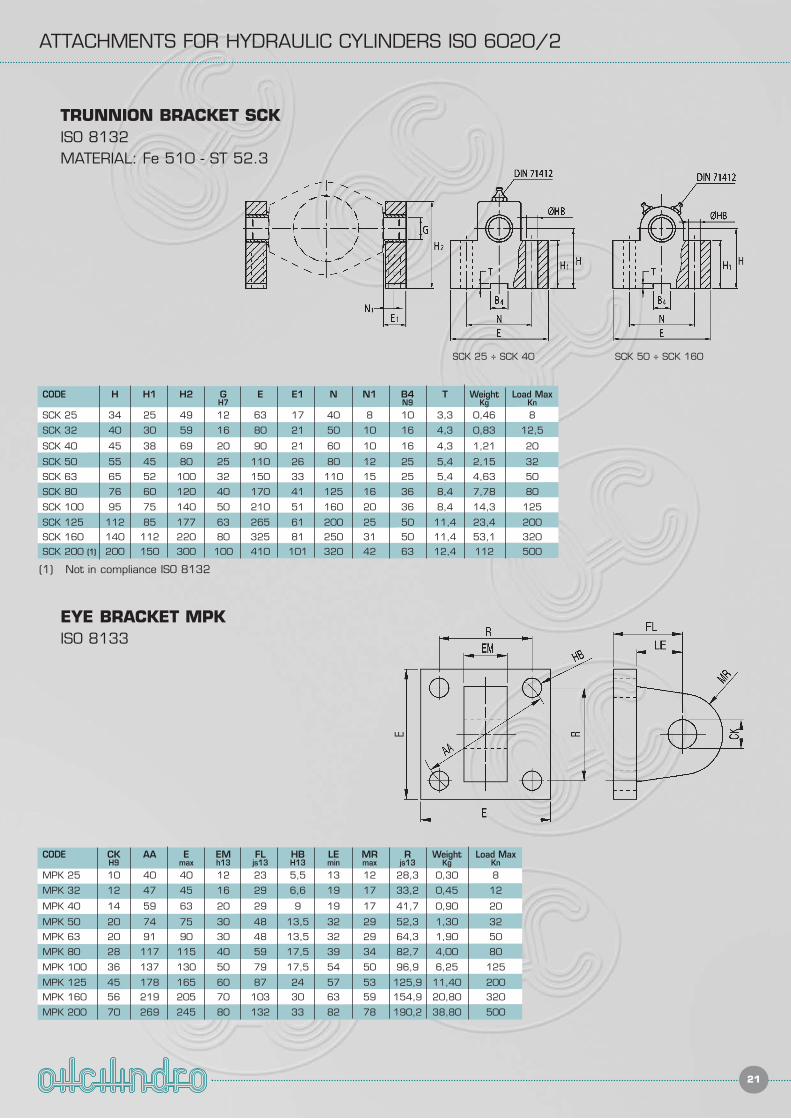
TRUNNION BRACKET SCKISO 8132MATERIAL: Fe 510 - ST 52.3
EYE BRACKET MPKISO 8133
CODE CK AA E EM FL HB LE MR R Weight Load MaxH9 max h13 js13 H13 min max js13 Kg Kn
MPK 25 10 40 40 12 23 5,5 13 12 28,3 0,30 8
MPK 32 12 47 45 16 29 6,6 19 17 33,2 0,45 12
MPK 40 14 59 63 20 29 9 19 17 41,7 0,90 20
MPK 50 20 74 75 30 48 13,5 32 29 52,3 1,30 32
MPK 63 20 91 90 30 48 13,5 32 29 64,3 1,90 50
MPK 80 28 117 115 40 59 17,5 39 34 82,7 4,00 80
MPK 100 36 137 130 50 79 17,5 54 50 96,9 6,25 125
MPK 125 45 178 165 60 87 24 57 53 125,9 11,40 200
MPK 160 56 219 205 70 103 30 63 59 154,9 20,80 320
MPK 200 70 269 245 80 132 33 82 78 190,2 38,80 500
SCK 25 ÷ SCK 40 SCK 50 ÷ SCK 160
CODE H H1 H2 G E E1 N N1 B4 T Weight Load MaxH7 N9 Kg Kn
SCK 25 34 25 49 12 63 17 40 8 10 3,3 0,46 8
SCK 32 40 30 59 16 80 21 50 10 16 4,3 0,83 12,5
SCK 40 45 38 69 20 90 21 60 10 16 4,3 1,21 20
SCK 50 55 45 80 25 110 26 80 12 25 5,4 2,15 32
SCK 63 65 52 100 32 150 33 110 15 25 5,4 4,63 50
SCK 80 76 60 120 40 170 41 125 16 36 8,4 7,78 80
SCK 100 95 75 140 50 210 51 160 20 36 8,4 14,3 125
SCK 125 112 85 177 63 265 61 200 25 50 11,4 23,4 200
SCK 160 140 112 220 80 325 81 250 31 50 11,4 53,1 320
SCK 200 200 150 300 100 410 101 320 42 63 12,4 112 500(1)
(1) Not in compliance ISO 8132
ATTACHMENTS FOR HYDRAULIC CYLINDERS ISO 6020/2
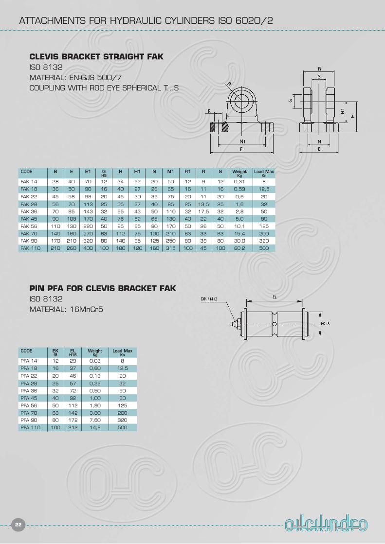
22
CODE B E E1 G H H1 N N1 R1 R S Weight Load MaxH9 Kg Kn
FAK 14 28 40 70 12 34 22 20 50 12 9 12 0,31 8
FAK 18 36 50 90 16 40 27 26 65 16 11 16 0,59 12,5
FAK 22 45 58 98 20 45 30 32 75 20 11 20 0,9 20
FAK 28 56 70 113 25 55 37 40 85 25 13,5 25 1,6 32
FAK 36 70 85 143 32 65 43 50 110 32 17,5 32 2,8 50
FAK 45 90 108 170 40 76 52 65 130 40 22 40 5,0 80
FAK 56 110 130 220 50 95 65 80 170 50 26 50 10,1 125
FAK 70 140 160 270 63 112 75 100 210 63 33 63 15,4 200
FAK 90 170 210 320 80 140 95 125 250 80 39 80 30,0 320
FAK 110 210 260 400 100 180 120 160 315 100 45 100 60,2 500
CLEVIS BRACKET STRAIGHT FAKISO 8132MATERIAL: EN-GJS 500/7COUPLING WITH ROD EYE SPHERICAL T...S
CODE EK EL Weight Load Maxf8 H16 Kg Kn
PFA 14 12 29 0,03 8
PFA 18 16 37 0,60 12,5
PFA 22 20 46 0,13 20
PFA 28 25 57 0,25 32
PFA 36 32 72 0,50 50
PFA 45 40 92 1,00 80
PFA 56 50 112 1,90 125
PFA 70 63 142 3,80 200
PFA 90 80 172 7,60 320
PFA 110 100 212 14,8 500
PIN PFA FOR CLEVIS BRACKET FAKISO 8132MATERIAL: 16MnCr5
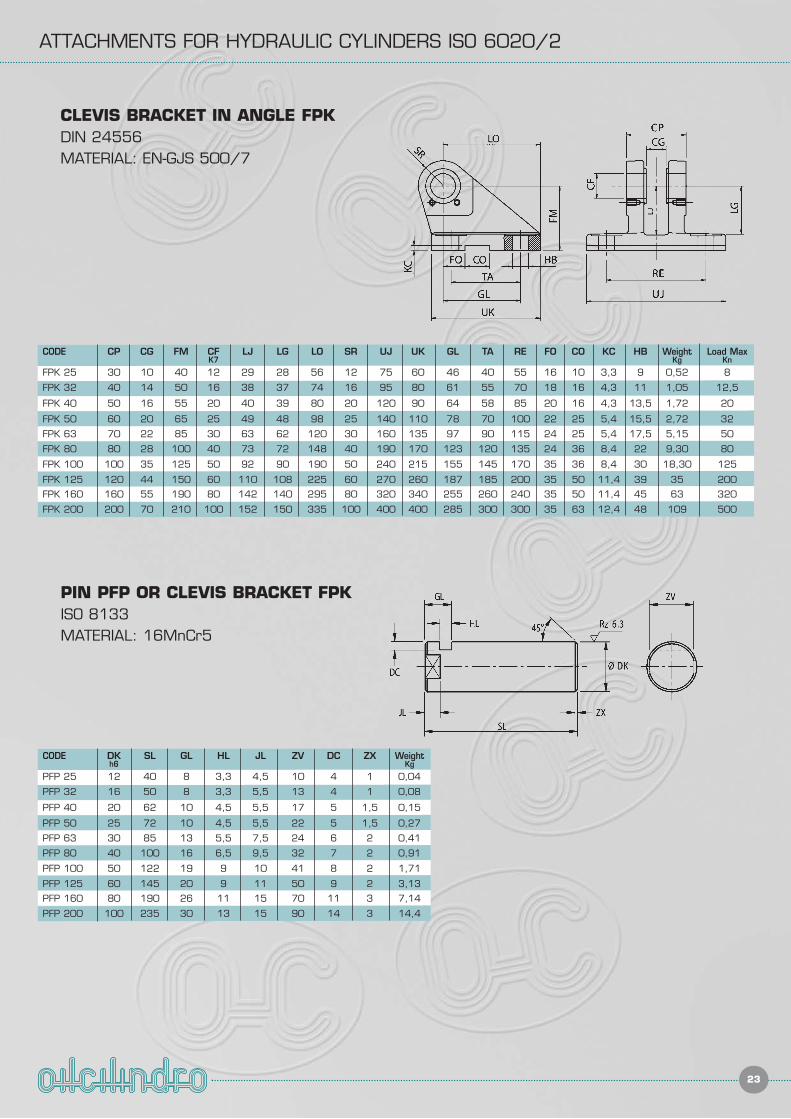
ATTACHMENTS FOR HYDRAULIC CYLINDERS ISO 6020/2
23
CODE CP CG FM CF LJ LG LO SR UJ UK GL TA RE FO CO KC HB Weight Load MaxK7 Kg Kn
FPK 25 30 10 40 12 29 28 56 12 75 60 46 40 55 16 10 3,3 9 0,52 8
FPK 32 40 14 50 16 38 37 74 16 95 80 61 55 70 18 16 4,3 11 1,05 12,5
FPK 40 50 16 55 20 40 39 80 20 120 90 64 58 85 20 16 4,3 13,5 1,72 20
FPK 50 60 20 65 25 49 48 98 25 140 110 78 70 100 22 25 5,4 15,5 2,72 32
FPK 63 70 22 85 30 63 62 120 30 160 135 97 90 115 24 25 5,4 17,5 5,15 50
FPK 80 80 28 100 40 73 72 148 40 190 170 123 120 135 24 36 8,4 22 9,30 80
FPK 100 100 35 125 50 92 90 190 50 240 215 155 145 170 35 36 8,4 30 18,30 125
FPK 125 120 44 150 60 110 108 225 60 270 260 187 185 200 35 50 11,4 39 35 200
FPK 160 160 55 190 80 142 140 295 80 320 340 255 260 240 35 50 11,4 45 63 320
FPK 200 200 70 210 100 152 150 335 100 400 400 285 300 300 35 63 12,4 48 109 500
CLEVIS BRACKET IN ANGLE FPKDIN 24556MATERIAL: EN-GJS 500/7
PIN PFP OR CLEVIS BRACKET FPKISO 8133MATERIAL: 16MnCr5
CODE DK SL GL HL JL ZV DC ZX Weighth6 Kg
PFP 25 12 40 8 3,3 4,5 10 4 1 0,04
PFP 32 16 50 8 3,3 5,5 13 4 1 0,08
PFP 40 20 62 10 4,5 5,5 17 5 1,5 0,15
PFP 50 25 72 10 4,5 5,5 22 5 1,5 0,27
PFP 63 30 85 13 5,5 7,5 24 6 2 0,41
PFP 80 40 100 16 6,5 9,5 32 7 2 0,91
PFP 100 50 122 19 9 10 41 8 2 1,71
PFP 125 60 145 20 9 11 50 9 2 3,13
PFP 160 80 190 26 11 15 70 11 3 7,14
PFP 200 100 235 30 13 15 90 14 3 14,4
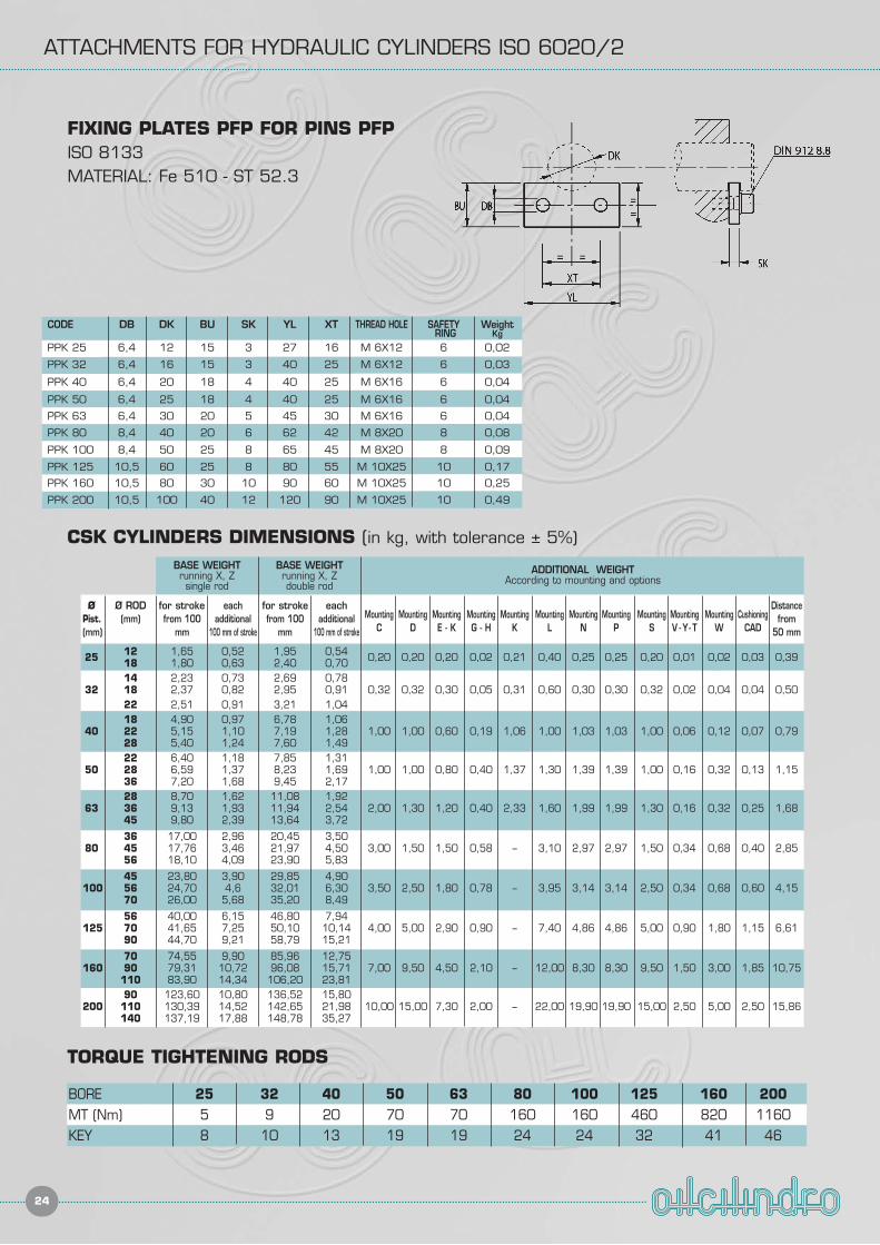
ATTACHMENTS FOR HYDRAULIC CYLINDERS ISO 6020/2
24
CSK CYLINDERS DIMENSIONS (in kg, with tolerance ± 5%)
Ø Ø ROD for stroke each for stroke eachMounting Mounting Mounting Mounting Mounting Mounting Mounting Mounting Mounting Mounting Mounting Cushioning
DistancePist. (mm) from 100 additional from 100 additional
C D E - K G - H K L N P S V - Y- T W CADfrom
(mm) mm 100 mm of stroke mm 100 mm of stroke 50 mm
25 12 1,65 0,52 1,95 0,54 0,20 0,20 0,20 0,02 0,21 0,40 0,25 0,25 0,20 0,01 0,02 0,03 0,3918 1,80 0,63 2,40 0,7014 2,23 0,73 2,69 0,78
32 18 2,37 0,82 2,95 0,91 0,32 0,32 0,30 0,05 0,31 0,60 0,30 0,30 0,32 0,02 0,04 0,04 0,5022 2,51 0,91 3,21 1,0418 4,90 0,97 6,78 1,06
40 22 5,15 1,10 7,19 1,28 1,00 1,00 0,60 0,19 1,06 1,00 1,03 1,03 1,00 0,06 0,12 0,07 0,7928 5,40 1,24 7,60 1,4922 6,40 1,18 7,85 1,31
50 28 6,59 1,37 8,23 1,69 1,00 1,00 0,80 0,40 1,37 1,30 1,39 1,39 1,00 0,16 0,32 0,13 1,1536 7,20 1,68 9,45 2,1728 8,70 1,62 11,08 1,92
63 36 9,13 1,93 11,94 2,54 2,00 1,30 1,20 0,40 2,33 1,60 1,99 1,99 1,30 0,16 0,32 0,25 1,6845 9,80 2,39 13,64 3,72
36 17,00 2,96 20,45 3,5080 45 17,76 3,46 21,97 4,50 3,00 1,50 1,50 0,58 – 3,10 2,97 2,97 1,50 0,34 0,68 0,40 2,85
56 18,10 4,09 23,90 5,83
45 23,80 3,90 29,85 4,90100 56 24,70 4,6 32,01 6,30 3,50 2,50 1,80 0,78 – 3,95 3,14 3,14 2,50 0,34 0,68 0,60 4,15
70 26,00 5,68 35,20 8,49
56 40,00 6,15 46,80 7,94125 70 41,65 7,25 50,10 10,14 4,00 5,00 2,90 0,90 – 7,40 4,86 4,86 5,00 0,90 1,80 1,15 6,61
90 44,70 9,21 58,79 15,21
70 74,55 9,90 85,96 12,75160 90 79,31 10,72 96,08 15,71 7,00 9,50 4,50 2,10 – 12,00 8,30 8,30 9,50 1,50 3,00 1,85 10,75
110 83,90 14,34 106,20 23,8190 123,60 10,80 136,52 15,80
200 110 130,39 14,52 142,65 21,98 10,00 15,00 7,30 2,00 – 22,00 19,90 19,90 15,00 2,50 5,00 2,50 15,86140 137,19 17,88 148,78 35,27
BASE WEIGHTrunning X, Zsingle rod
BASE WEIGHTrunning X, Zdouble rod
ADDITIONAL WEIGHTAccording to mounting and options
TORQUE TIGHTENING RODS
BORE 25 32 40 50 63 80 100 125 160 200MT (Nm) 5 9 20 70 70 160 160 460 820 1160KEY 8 10 13 19 19 24 24 32 41 46
FIXING PLATES PFP FOR PINS PFPISO 8133MATERIAL: Fe 510 - ST 52.3
CODE DB DK BU SK YL XT THREAD HOLE SAFETY WeightRING Kg
PPK 25 6,4 12 15 3 27 16 M 6X12 6 0,02
PPK 32 6,4 16 15 3 40 25 M 6X12 6 0,03
PPK 40 6,4 20 18 4 40 25 M 6X16 6 0,04
PPK 50 6,4 25 18 4 40 25 M 6X16 6 0,04
PPK 63 6,4 30 20 5 45 30 M 6X16 6 0,04
PPK 80 8,4 40 20 6 62 42 M 8X20 8 0,08
PPK 100 8,4 50 25 8 65 45 M 8X20 8 0,09
PPK 125 10,5 60 25 8 80 55 M 10X25 10 0,17
PPK 160 10,5 80 30 10 90 60 M 10X25 10 0,25
PPK 200 10,5 100 40 12 120 90 M 10X25 10 0,49