Embed Size (px)
Citation preview

Pump Systemsand Accessories
Catalogue Drainage and Sewage
Wastewater and SewageLifting Units, PumpsStations
Catalogue C3 - 50 Hz - 2009 C3

7
1
2
3
5
4
6
8
9
10
13
12
11
Wilo-Jet WJ
B1
1
Wilo-Sub TWI 5-SE P & P
B1
2
Wilo-SilentMaster
B1
3
Wilo-Sub TWU 3
B1
4
Wilo-RainSystemAF Comfort
B1
5
Wilo-Comfort-Vario COR
B4
6
Wilo-Comfort-Vario CO 1/MVIE
B4
6
Wilo-StratosECO
A1
7
Wilo-Safe
A1
8
Wilo-Star-Z 15 TT
A1
9
Wilo-DrainLift Con
C3
10
Wilo-Stratos
A1
11
Wilo-Drain TM/TMW 32 Twister
C1
12
Wilo-DrainLift S
C3
13
Series Catalogue
Wilo-EMU KS
C1
1
Wilo-RainSystemAF 150
B1
2
Wilo-Comfort-VarioCOR 4
B4
3
Wilo-Stratos-D
A1
4
Wilo-CronoLine-IL-E
A2
5
Wilo-TOP-Z
A1
6
Wilo-Stratos
A1
7
Wilo-CronoBloc-BL
A3
8
Wilo-CronoBloc-BL
A3
8
Wilo-DrainLift M
C3
9
Wilo-DrainLift WS
C3
10
7
1
2
3
6
5
8
9
10
4
Series Catalogue

2 Subject to change 09/2007 WILO AG
Programme overview and fields of application
Wastewater and sewage lifting units, pumps stations
System type Macera-tor
Floor-mounted installa-tion
Con-cealed floor installa-tion
Main field of application
Page
Condensate/wastewater/drainage
Wilo-DrainLift Con – • – – – – – S/M/C 15
Wilo-DrainLift TMP – • – S – – – – 18
Wilo-DrainLift Box – – • S/M S/M – – – 23
Sewage/faeces
Wilo-DrainLift KH • • – S S S – – 38
Wilo-DrainLift XS-F – • – S S S – – 42
Wilo-DrainLift S – • – S/M S/M S/M – S 47
Wilo-DrainLift M – • – S/M S/M S/M C S/M 54
Wilo-DrainLift L – • – M/C M/C M/C C M/C 63
Wilo-DrainLift XL – • – M/C M/C M/C C M/C 71
Wilo-DrainLift XXL – • – C C C C C 77
Wilo-DrainLift FTS – • – C C C C C 85
Pumps stations
Wilo-DrainLift WS 40-50 • • • S/M/C S/M/C S/M/C C S/M/C 96
Wilo-DrainLift WS 625 • – • S/M/C S/M/C S/M/C C C 97
Wilo-DrainLift WS 900/1100 • – • S/M/C S/M/C S/M/C C C 105
Key: Fields of application:
• Can be used/applicable- Cannot be used/not applicableS Single- and two-family housesM Multi-family houseC Commercial
Wastewater/drainage Production sewage
Wastewater/coarse contaminantsCondensateCalorific value/air-conditioning devices
Sewage/faeces

Wilo-DrainLift XS-F.
Automatic sewage lifting unit.*For front wall installation.
Ideal for the guest bathroom in the basement.For new buildings, renovations
and modernisation.
The Wilo-DrainLift XS-F is the perfect solution for complete guest bathrooms underneath the drainage pipe level, e.g., in the basement. This automatic sewage lifting unit* is used for the disposal of sewage from wall-mounted toilets. Optionally, a wash stand, a showerand a bidet can be connected in the same room. The Wilo-DrainLift XS-F meets all requirementsfor a front wall installation and is thus ideally suited for new buildings, renovations andmodernisation. Flexible? We call this Pumpen Intelligenz.
www.wilo.com
* For limited use in accordance with EN 12050-3 and DIN 1986-100.
3
Contents
Wilo Catalogue C3 - 50 Hz - Wastewater and sewage lifting units, pumps stations
Cond
ensate/w
astewater/
draina
geSe
wag
e/faeces
Pumps
station
sElectrical
accessorie
sWilo
-Drain
General notes and abbreviations 6
Planning guide 8
Condensate/wastewater/drainage 12
Wilo-DrainLift ConWilo-DrainLift TMPWilo-DrainLift Box
Sewage/faeces 28
Wilo-DrainLift KHWilo-DrainLift XS-FWilo-DrainLift SWilo-DrainLift M, L, XLWilo-DrainLift XXLWilo-DrainLift FTS
Pumps stations 94
Wilo-DrainLift WS 40-50Wilo-DrainLift WS 625Wilo-DrainLift WS 900/1100
Electrical accessories Wilo-Drain 118
Recommended accessoriesProduct descriptions

4 Subject to change 09/2008 WILO SE
Condensate/wastewater/drainageContents
Wastewater lifting units
Series overview 12
Wilo-DrainLift Con 15
Wilo-DrainLift TMP 18
Wilo-DrainLift Box 23
Sewage lifting units
Series overview 28
Wilo-DrainLift KH 38
Wilo-DrainLift XS-F 42
Wilo-DrainLift S 47
Wilo-DrainLift M, L, XL 54
Wilo-DrainLift XXL 77
Wilo-DrainLift FTS 85
Pumps stations
Planning guide 92
Series overview 94
Wilo-DrainLift WS 40 Basic, WS 40-50 96
Wilo-DrainLift WS 625 97
Wilo-DrainLift WS 900/1100 105
Electrical accessories Wilo-Drain
Recommended accessories 118
Product descriptions 125
Switchgear Wilo-EC-Drain 1x4,0 125
Switchgear Wilo-EC-Drain 2x4,0 125
Switchgear Wilo-DrainControl PL 1 126
Switchgear Wilo-DrainControl PL 1 WS 126
Switchgear Wilo-DrainControl PL 2 127
Switchgear Wilo-DrainControl PL 2 WS 127
Switchgear Wilo-DrainControl 1/2 128
Small alarm switchgear Wilo KAS 128
Wilo Drain-Alarm 2 128
Alarm switchgears Wilo-AlarmControl 1/2 129
Motor switchgear/motor protection plug CEE 129
Level sensor 129
Float switch MS1 130
Float switch WA 130
Ex-rated cut-off relay 130

5
Condensate/wastewater/drainageContents
Wilo Catalogue C3 - 50 Hz - Wastewater and sewage lifting units, pumps stations
Cond
ensate/w
astewater/
draina
geSe
wag
e/faeces
Pumps
station
sElectrical
accessorie
sWilo
-Drain
Electrical accessories Wilo-Drain (continued)
Breakdown barrier 130
Switch cabinet, outdoor installation for Wilo-DrainControl 131
Flash light 131
Signal horn 131
Dynamic pressure system 131
Bubbling-through system 132
Tripping unit Wilo-SK 545 132

6 Subject to change 09/2008 WILO SE
General notes and abbreviations
Abbreviations and what they mean Material designations and their meanings
Abbreviation Meaning
1~ 1-phase alternating current
1/min Pump speed
3~ 3-phase alternating current
-A Float switch attached
D Direct activation
DI Leakage detection
DM Three-phase motor with direct activation
DN Nominal diameter of the flange connection
EBM Individual run signal
EM Single-phase motor with starting capacitor
ESM Individual fault signal
GRD/GLRD Mechanical seal
H Delivery head
IA Starting current
IN Rated current; current at P2
Inst. Installation: H = horizontal, V = vertical
LB Readiness for delivery (L = stock article, C = available in 2 weeks, K = available in 4 weeks, A = available on request)
P1 Power consumption (power supplied from the mains system)
PN = P2 Rated motor power
PN Pressure class in bar (e.g. PN10 = suitable up to 10 bar)
PTC Positive temperature coefficient (PTC thermistor sensor)
PT 100 Platinum temperature sensor with a resistance value of 100 � at 0 °C
Q (=�) Volume flow
-S Float switch attached
SBM Run signal or collective run signal
SSM Fault signal or collective fault signal
WSK Thermal winding contacts (in motor for monitoring the winding temperature, full motor protection by additional tripping unit)
Y/� Star/delta activation
� Operating mode of double pumps:Individual operation of the respective duty pump
� Operating mode of double pumps:Parallel operation of both pumps
� Number of poles of electric motors:2-pole motor = approx. 2900 1/min with 50 Hz
� Number of poles of electric motors:4-pole motor = approx. 1450 1/min with 50 Hz
� Number of poles of electric motors:6-pole motor = approx. 950 1/min with 50 Hz
Material Meaning
1.4021 Chrome steel X20Cr13
1.4057 Chrome steel X17CrNi16-2
1.4112 Chrome steel X 90 Cr Mo V 18
1.4122 Chrome steel X39CrMo17-1
1.4301 Chrome-nickel steel X5CrNi18-10
1.4305 Chrome-nickel steel X8CrNiS18-9
1.4306 Chrome-nickel steel X2CrNi19-11
1.4308 Chrome-nickel steel GX5CrNi19-10
1.4401 Chrome-nickel-molybdenum steel X5CrNiMo17-12-2
1.4408 Chrome-nickel-molybdenum steel GX5CrNiMo19-11-2
1.4462 Chrome-nickel-molybdenum steel X2CrNiMoN22-5-3
1.4470 Chrome-nickel-molybdenum steel GX2CrNiMoN22-5-3
1.4517 Chrome-nickel-molybdenum steel with copper ad-dition GX2CrNiMoCuN25-6-3-3
1.4541 Chrome-nickel steel with titanium addition X6CrNiTi18-10
1.4542 Chrome-nickel steel with copper and niobium addi-tions X5CrNiCuNb16-4
1.4571 Chrome-nickel steel with titanium additionX6CrNiMoTi17-12-2
1.4581 Chrome-nickel-molybdenum steel with niobium ad-dition GX5CrNiMoNb19-11-2
Abrasite Chilled cast iron material for use in strongly abrasive fluids
Al Light metal material (aluminium)
Al-oxide Aluminium oxide
C Carbon
Ceram Ceramic coating; coating with very high adhesive strength, protection against corrosion and abrasion
Composite High-strength plastic material
Cr Chromium
EN-GJL Cast iron (cast iron with lamellar graphite)
EN-GJS Cast iron (nodular cast iron, also known as spheroidal cast iron)
G-AlSi12 Die-cast aluminium
GFK Fibreglass plastic
GG See EN-GJL
GGG See EN-GJS
Inox Stainless steel
PA 30GF See Composite

7
General notes and abbreviations
Wilo Catalogue C3 - 50 Hz - Wastewater and sewage lifting units, pumps stations
Cond
ensate/w
astewater/
draina
geSe
wag
e/faeces
Pumps
station
sElectrical
accessorie
sWilo
-Drain
Wear and tearPumps or parts of pumps are subject to wear and tear in accordance with the latest technology (DIN 31051/DIN-EN 13306). This wear may vary depending on operating parameters (temperature, pressure, speed, water conditions) and the installation/usage situation and may result in the malfunction or failure at different times of the afore-mentioned products/components, including their electrical/electro-nic circuitry.Wearing parts are all components subject to rotary or dynamic stress, including electronic components under tension, in particular:
- Seals (including mechanical seals), seal rings- Stuffing boxes - Bearings and shafts- Impellers and pump components-Wear rings and counter rings- Stationary wear rings/wear plates-Macerators - Capacitors- Relays/contactors/switches- Electronic circuits, semiconductor components, etc.
With pumps and fluid flow machines (such as submersible mixers and recirculation pumps) and their components that have a coating (cataphoretic coating, 2 K or ceram coating), this coating is subject to constant wear from the abrasive constituents of the fluid. For this reason the coating is also among the wearing parts of these units.
We do not accept any liability for faults or defects arising from natu-ral wear and tear.
Wilo – General Terms of Delivery and ServiceThe latest version of our General Terms of Delivery and Service can be found on the Internet at
www.wilo.com
Material Meaning
PE-HD High-density polyethylene
PP-GF30 Polypropylene, reinforced with 30% fibreglass
PUR Polyurethane
SiC Silicon carbide
St Steel
St.vz. Galvanised steel
V2A (A2) Material group, e.g. 1.4301, 1.4306
V4A (A4) Material group, e.g. 1.4404, 1.4571
8 Subject to change 09/2008 WILO SE
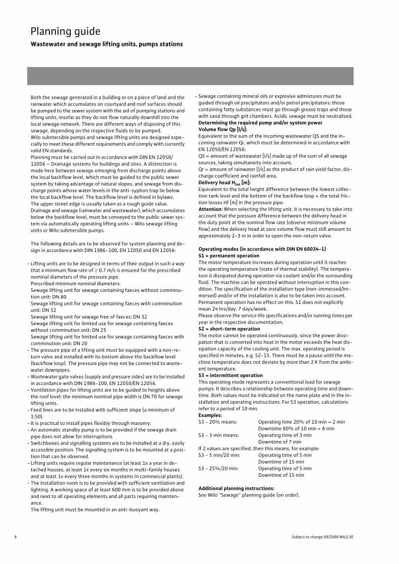
Planning guideWastewater and sewage lifting units, pumps stations
Both the sewage generated in a building or on a piece of land and the rainwater which accumulates on courtyard and roof surfaces should be pumped to the sewer system with the aid of pumping stations and lifting units, insofar as they do not flow naturally downhill into the local sewage network. There are different ways of disposing of this sewage, depending on the respective fluids to be pumped.Wilo submersible pumps and sewage lifting units are designed espe-cially to meet these different requirements and comply with currently valid EN standards.Planning must be carried out in accordance with DIN EN 12050/12056 – Drainage systems for buildings and sites. A distinction is made here between sewage emerging from discharge points above the local backflow level, which must be guided to the public sewer system by taking advantage of natural slopes, and sewage from dis-charge points whose water levels in the anti-syphon trap lie below the local backflow level. The backflow level is defined in bylaws. The upper street edge is usually taken as a rough guide value.Drainage and sewage (rainwater and wastewater), which accumulates below the backflow level, must be conveyed to the public sewer sys-tem via automatically operating lifting units – Wilo sewage lifting units or Wilo submersible pumps.
The following details are to be observed for system planning and de-sign in accordance with DIN 1986-100, EN 12050 and EN 12056:
- Lifting units are to be designed in terms of their output in such a way that a minimum flow rate of � 0.7 m/s is ensured for the prescribed nominal diameters of the pressure pipe.Prescribed minimum nominal diameters:Sewage lifting unit for sewage containing faeces without comminu-tion unit: DN 80 Sewage lifting unit for sewage containing faeces with comminution unit: DN 32Sewage lifting unit for sewage free of faeces: DN 32Sewage lifting unit for limited use for sewage containing faeces without comminution unit: DN 25Sewage lifting unit for limited use for sewage containing faeces with comminution unit: DN 20
-The pressure pipe of a lifting unit must be equipped with a non-re-turn valve and installed with its bottom above the backflow level (backflow loop). The pressure pipe may not be connected to waste-water downpipes.
-Wastewater gate valves (supply and pressure sides) are to be installed in accordance with DIN 1986-100, EN 12050/EN 12056.
-Ventilation pipes for lifting units are to be guided to heights above the roof level; the minimum nominal pipe width is DN 70 for sewage lifting units.
- Feed lines are to be installed with sufficient slope (a minimum of 1:50).
- It is practical to install pipes flexibly through masonry.-An automatic standby pump is to be provided if the sewage drain pipe does not allow for interruptions.
- Switchboxes and signalling systems are to be installed at a dry, easily accessible position. The signalling system is to be mounted at a posi-tion that can be observed.
- Lifting units require regular maintenance (at least 1x a year in de-tached houses, at least 1x every six months in multi-family houses and at least 1x every three months in systems in commercial plants).
-The installation room is to be provided with sufficient ventilation and lighting. A working space of at least 600 mm is to be provided above and next to all operating elements and all parts requiring mainten-ance.The lifting unit must be mounted in an anti-buoyant way.
- Sewage containing mineral oils or explosive admixtures must be guided through oil precipitators and/or petrol precipitators; those containing fatty substances must go through grease traps and those with sand through grit chambers. Acidic sewage must be neutralised.Determining the required pump and/or system powerVolume flow Qp [l/s]:Equivalent to the sum of the incoming wastewater QS and the in-coming rainwater Qr, which must be determined in accordance with EN 12050/EN 12056:QS = amount of wastewater [l/s] made up of the sum of all sewage sources, taking simultaneity into account,Qr = amount of rainwater [l/s] as the product of rain yield factor, dis-charge coefficient and rainfall area.Delivery head Htot [m]:Equivalent to the total height difference between the lowest collec-tion tank level and the bottom of the backflow loop + the total fric-tion losses Hf [m] in the pressure pipe.Attention: When selecting the lifting unit, it is necessary to take into account that the pressure difference between the delivery head in the duty point at the nominal flow rate (observe minimum volume flow) and the delivery head at zero volume flow must still amount to approximately 2-3 m in order to open the non-return valve.
Operating modes (in accordance with DIN EN 60034-1)S1 = permanent operationThe motor temperature increases during operation until it reaches the operating temperature (state of thermal stability). The tempera-ture is dissipated during operation via coolant and/or the surrounding fluid. The machine can be operated without interruption in this con-dition. The specification of the installation type (non-immersed/im-mersed) and/or of the installation is also to be taken into account. Permanent operation has no effect on this. S1 does not explicitly mean 24 hrs/day, 7 days/week.Please observe the service life specifications and/or running times per year in the respective documentation.S2 = short-term operationThe motor cannot be operated continuously, since the power dissi-pation that is converted into heat in the motor exceeds the heat dis-sipation capacity of the cooling unit. The max. operating period is specified in minutes, e.g. S2-15. There must be a pause until the ma-chine temperature does not deviate by more than 2 K from the ambi-ent temperature.S3 = intermittent operationThis operating mode represents a conventional load for sewage pumps. It describes a relationship between operating time and down-time. Both values must be indicated on the name plate and in the in-stallation and operating instructions. For S3 operation, calculations refer to a period of 10 min.Examples:S3 - 20% means: Operating time 20% of 10 min = 2 min
Downtime 80% of 10 min = 8 minS3 - 3 min means: Operating time of 3 min
Downtime of 7 minIf 2 values are specified, then this means, for example:S3 - 5 min/20 min: Operating time of 5 min
Downtime of 15 minS3 - 25%/20 min: Operating time of 5 min
Downtime of 15 min
Additional planning instructions:See Wilo “Sewage” planning guide (on order).

9
Planning guideWastewater and sewage lifting units, pumps stations
Wilo Catalogue C3 - 50 Hz - Wastewater and sewage lifting units, pumps stations
Cond
ensate/w
astewater/
draina
geSe
wag
e/faeces
Pumps
station
sElectrical
accessorie
sWilo
-Drain
Wastewater lifting unit (sewage without faeces) in accordance with EN 12050-2
Double pumps – Wilo-Drain Twister
Double pump drainage station Wilo-Drain Twister1 Submersible pump (2 x)2 Pressure pipe DN 32 with Y-piece3 Non-return valve4 Backflow loop5 Backflow level6 Sewer7 Switchgear8 Float switch for level and alarm control
Configuration of the backflow loopThe backflow loop should not be set up di-rectly in vertical position above the position of the lifting unit, if possible. The rest of the sewage pipe is to be installed on a slope down to the connection to the sewer sys-tem.
Wastewater and sewage lifting unit (sewage with faecal content) in accordance with EN 12050-1
Double system – Wilo-DrainLift XXL
1 Gate valve DN 100 or DN 1502 Flange piece with hose and hose clips
DN 100 or DN 1503 Flexible hose connection for ventila-
tion4 Connection kit, tank with pump, 2 gate
valves and ventilation flange with hose5 Diaphragm hand pump 1 ½"6 Non-return valve DN 80 or DN 1007 Gate valve DN 80 or DN 1008 Flange piece with hose and hose clips
DN 80 or DN 1009 3-way cock10 Y-pipe DN 80 or DN 10011 Microprocessor-controlled switchgear12 KAS, small alarm switchgear with sig-
nalling tone13 Flexible hose connection for diaphragm
hand pump14 Fitting support for weight relief
Rückstauebene(meist Straßen-oberkante)
Zulauf
Entwässerungspumpe
Entlüftung
1
14
2 3
4
5
6
78
9
10
11
12
13
Backflow level(generally upper street edge)
Inlet
Drainage pump
Ventilation

10 Subject to change 09/2008 WILO SE
Planning guideWastewater and sewage lifting units, pumps stations
l
Pressure losses in rigid pipes
30,0
[m] [m]
20,0
10,0
8,0
6,0
4,0
2,0
1,0
0,8
0,6
0,4
0,2
0,1
30,0
20,0
10,0
8,0
6,0
4,0
2,0
1,0
0,8
0,6
0,4
0,2
0,1
0,1 10 20 400,2 1,0 2,0 4,0 100 200 400 [l/s] 1000 2000
0,4 1,0 2,0 4,0 10 20 40 100 200 400 1000 [m³/h] 6000DN
40
DN50
DN65
DN20
DN25
DN32
DN80
DN
100
DN
125
DN
150
DN200
DN250
DN300
DN350
DN
400
DN500
DN600
DN
700
DN800
DN900
DN
1000
0,4 m/s
0,6 m/s
0,8 m/s
1,5 m/s
1,0 m/s
2,0 m/s
3,0 m/s
4,0 m/s
0,4

11
Planning guideWastewater and sewage lifting units, pumps stations
Wilo Catalogue C3 - 50 Hz - Wastewater and sewage lifting units, pumps stations
Cond
ensate/w
astewater/
draina
geSe
wag
e/faeces
Pumps
station
sElectrical
accessorie
sWilo
-Drain

12 Subject to change 09/2008 WILO SE
Condensate/wastewater/drainageWastewater lifting units
Series overview Wilo-DrainLift Con, TMP, Box
14
Series: Wilo-DrainLift Con
>Condensate lifting unit> Application:• Pumping of condensate, can be used in- Condensing boiler technology
(an upstream neutralisation system must be provided for oil-fired boilers)
-Air-conditioning and refrigeration systems(e.g. refrigerators and evaporators)
Series: Wilo-DrainLift TMP
> Wastewater lifting unit> Application:• Automatic drainage for showers, washba-sins, washing machines/dishwashers, etc.
• Pumping of wastewater and drainage water free of faeces, fibres, grease and oil, and pumping of non-aggressive rainwater.
Series: Wilo-DrainLift Box
> Wastewater lifting unit> Application:• For concealed floor installation, can be used to drain-Rooms at risk of flooding-Garage entrances- Basement stairways- Showers, washbasins, washing machines, dishwashers
0 50 100 150 200 250 3000
1
2
3
4
5
H[m
]
Wilo-DrainLift Con
Q [l/h]
Wilo-Drain TMP
2
3
0
5
6
7
8
9
4
1
H [
m]
0 4 82 6 10 Q[m³/h]
0
2
4
6
8
10
12
H[m
]
0 2 4 6 8 10 12 14 Q[m3/h]
Wilo-DrainLift Box

13
Condensate/wastewater/drainageWastewater lifting units
Series overview Wilo-DrainLift Con, TMP, Box
Wilo Catalogue C3 - 50 Hz - Wastewater and sewage lifting units, pumps stations
Cond
ensate/w
astewater/
draina
geSe
wag
e/faeces
Pumps
station
sElectrical
accessorie
sWilo
-Drain
Series: Wilo-DrainLift Con
>Product advantages• Low-noise operation (� 43 dB[A])• 2 inlet openings• Standard-equipped with alarm contact
(NC/NO contact)• Easy to install• The motor unit can be reversed by 180°.• Variable inlets/drains• Suitable for condensates with a pH value of � 2.4
>Additional information: Page• Equipment/function . . . . . . . . . . . . . . 14• Series description . . . . . . . . . . . . . . . . 15• Technical data . . . . . . . . . . . . . . . . . . . 16• Pump curves, dimensions . . . . . . . . . 17
Series: Wilo-DrainLift TMP
>Product advantages• Modern design• Shower drainage is possible from a height of 110 mm (only in conjunction with TMP 32-0,5)
• Low-noise operation • Easy to maintain due to built-in submersible pump (TMP 40)
• Suitable for aggressive fluids (TMP 40/11 HD)
>Additional information: Page• Equipment/function . . . . . . . . . . . . . . 14• Series description . . . . . . . . . . . . . . . . 18• Technical data . . . . . . . . . . . . . . . . . . . 19• Pump curves . . . . . . . . . . . . . . . . . . . . 20• Dimensions . . . . . . . . . . . . . . . . . . . . . . 21• Installation example . . . . . . . . . . . . . . 22
Series: Wilo-DrainLiftBox
>Product advantages• Easy to install due to integrated pump and non-return valve
• Large tank volume• Easy to maintain• Pumps with pressure pipe that can be pulled• Stainless steel tile frame with trap• With extra connection for a second tank
>Additional information: Page• Equipment/function . . . . . . . . . . . . . . 14• Series description . . . . . . . . . . . . . . . . 23• Technical data . . . . . . . . . . . . . . . . . . . 24• Pump curves . . . . . . . . . . . . . . . . . . . . 25• Dimensions . . . . . . . . . . . . . . . . . . . . . . 26

14 Subject to change 09/2008 WILO SE
Condensate/wastewater/drainageWastewater lifting units
Equipment/ function Wilo-DrainLift Con, TMP, Box
Wilo-DrainLift …
Con TMP 32-0,5 TMP 40/8TMP 40/11 Box 32 Box 40
Sealing of pumps/motor
On fluid side: Mechanical seal – – • • •Oil barrier chamber – – – • •
Design
Pump position: Submersible pump in the tank – • • • •Motor components outside the tank • – – – –
Single-pump system • • • • •Vortex impeller • • • • •Open multi-channel impeller – –
-
– –
Patented turbulator – – – • –
Materials
Motor Stainless steel • • • • •Hydraulic housing: Plastic • • PP-GF30 PP-GF30 –
Cast iron – – – – EN-GJL-200
Impeller: Plastic • • • • –
Cast iron – – – – •Tank: Plastic ABS ABS PE PE PE
Equipment
Motor monitoring Temperature (WSK) – – • • •Level control: Float switch • – • • •
Pneumatic pressure sensor – • – – –
Alarm: Independent of mains – – – – –
Potential-free contact • – – – –
Pump cable detachable – – – – –
Ready-to-plug • • • • •Integrated non-return valve • • • • •Inlet seal – – – – –
Kit for pressure pipe connection – • • • •Fixation material • • • – –
Active carbon filter – • – – –
Pressure hose • – – – –
• = available, - = not available
15
Condensate/wastewater/drainageWastewater lifting units
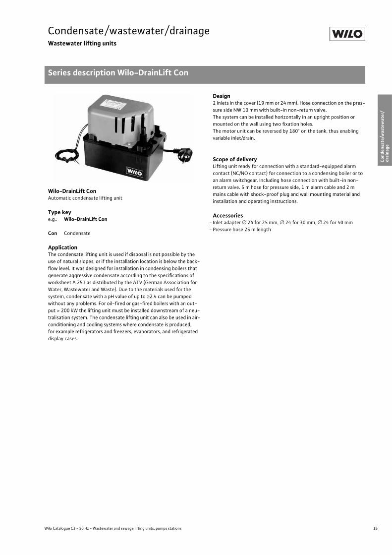
Series description Wilo-DrainLift Con
Wilo Catalogue C3 - 50 Hz - Wastewater and sewage lifting units, pumps stations
Cond
ensate/w
astewater/
draina
geSe
wag
e/faeces
Pumps
station
sElectrical
accessorie
sWilo
-Drain
Wilo-DrainLift ConAutomatic condensate lifting unit
Type keye.g.: Wilo-DrainLift Con
Con Condensate
ApplicationThe condensate lifting unit is used if disposal is not possible by the use of natural slopes, or if the installation location is below the back-flow level. It was designed for installation in condensing boilers that generate aggressive condensate according to the specifications of worksheet A 251 as distributed by the ATV (German Association for Water, Wastewater and Waste). Due to the materials used for the system, condensate with a pH value of up to �2.4 can be pumped without any problems. For oil-fired or gas-fired boilers with an out-put > 200 kW the lifting unit must be installed downstream of a neu-tralisation system. The condensate lifting unit can also be used in air-conditioning and cooling systems where condensate is produced, for example refrigerators and freezers, evaporators, and refrigerated display cases.
Design2 inlets in the cover (19mm or 24 mm). Hose connection on the pres-sure side NW 10mm with built-in non-return valve.The system can be installed horizontally in an upright position or mounted on the wall using two fixation holes. The motor unit can be reversed by 180° on the tank, thus enabling variable inlet/drain.
Scope of deliveryLifting unit ready for connection with a standard-equipped alarm contact (NC/NO contact) for connection to a condensing boiler or to an alarm switchgear. Including hose connection with built-in non-return valve. 5m hose for pressure side, 1 m alarm cable and 2m mains cable with shock-proof plug and wall mounting material and installation and operating instructions.
Accessories- Inlet adapter � 24 for 25mm, � 24 for 30mm, � 24 for 40mm-Pressure hose 25 m length

16 Subject to change 09/2008 WILO SE
Condensate/wastewater/drainageWastewater lifting units
Technical data Wilo-DrainLift Con
Wilo-DrainLift Con
Approved fluids
Charged condensate (pH � 2.4) •
Electrical connection
Mains connection [V] 1~230
Power consumption P1 [kW] 0.08
Nominal current [A] 0.8
Mains frequency [Hz] 50
Cable length from system to switchgear/plug [m] 2
Approved field of application
Operating mode S3 - 15%
Fluid temperature, maximum [°C] 80
Connections
Pressure port [mm] 12
Inlet connection [mm] 19/24
Motor
Protection class IP 20
Dimensions/weights
Gross volume [l] 1.5
Weight [kg] 2
• = available or approved, - = not available or not approved

17
Condensate/wastewater/drainageWastewater lifting units
Pump curve, dimensions Wilo-DrainLift Con
Wilo Catalogue C3 - 50 Hz - Wastewater and sewage lifting units, pumps stations
Cond
ensate/w
astewater/
draina
geSe
wag
e/faeces
Pumps
station
sElectrical
accessorie
sWilo
-Drain
Wilo-DrainLift Con
2-pole, 50 Hz
Dimension drawing
[l/h]0 50 100 150 200 250 300 350
H
0
2
4
3
5
6
1
Q
Wilo-DrainLift Con [m]
21
Ø 12
195
16
9,5
13
0
82
,5

18 Subject to change 09/2008 WILO SE
Condensate/wastewater/drainageWastewater lifting units
Series description Wilo-DrainLift TMP
Wilo-DrainLift TMPWastewater lifting unit (floor-mounted installation)
Type keye.g.: Wilo-DrainLift TMP 32-0,5
TMP Wastewater lifting unit (floor-mounted installation)32 Nominal diameter of the pressure port (DN 32/G 1¼)– 0,5 Nominal motor power [kW]
e.g.: Wilo-DrainLift TMP 40/8
TMP Wastewater lifting unit (floor-mounted installation)40 Nominal diameter of the pressure port (DN 40)/8 Maximum delivery head [m]
ApplicationWastewater lifting unit for the automatic drainage of showers, wash-basins, washing machines/dishwashers, etc., in both old and new buildings where the wastewater cannot be discharged to the sewer system via natural slopes and/or for the disposal of wastewater that accumulates below the backflow level. For pumping non-aggressive wastewater and drainage waters that are free of faeces, fibre, grease and oil. DIN EN 12050-2 as well as DIN 1986-100 are to be observed.Attention:Pumping faeces containing sewage in wastewater lifting units is not permitted. In these cases, it is necessary to use sewage lifting units of the series DrainLift KH32, DrainLift XS-F, DrainLift S to XXL, and FTS.
DesignAutomatically switching wastewater lifting unit ready for connection with all switchgear and control mechanisms required and a built-in non-return valve.
TMP 32Active carbon filter with overflow protection for ventilation and ex-haust, 2 DN 40 inlet connecting pieces at different height levels, DN 32 pressure port (G 1¼). Ventilation can also be performed at roof level by the use of self-sealing plug couplers (external pipe diameter 25mm).
TMP 40Flexible use via feed lines that are possible either at the side or from above (particularly advantageous for retrofitting installation), easy-maintenance system design with built-in Wilo-Drain TMW pump, DN pressure port. Optionally available as TMP 40/11 HD for aggressive fluids.
Scope of deliveryReady-for-connection, automatically switching wastewater lifting unit (with active carbon filter for TMP 32) and installation and oper-ating instructions.

19
Condensate/wastewater/drainageWastewater lifting units
Technical data Wilo-DrainLift TMP
Wilo Catalogue C3 - 50 Hz - Wastewater and sewage lifting units, pumps stations
Cond
ensate/w
astewater/
draina
geSe
wag
e/faeces
Pumps
station
sElectrical
accessorie
sWilo
-Drain
Wilo-DrainLift …
TMP 32-0,5 TMP 40/8 TMP 40/11 HD
Approved fluids
Domestic sewage without faeces • • •Domestic sewage containing faeces – – –
Washing machine soap and water mixture(without long-fibre constituents) • • •
Shower and bath water, unchlorinated • • •Charged condensate – – –
Electrical connection
Mains connection [V] 1~230 1~230 1~230
Power consumption P1 [kW] 0.33 0.45 0.75
Nominal motor power P2 [kW] 0.25 0.37 0.55
Nominal current [A] 1.5 2.1 3.6
Mains frequency [Hz] 50 50 50
Cable length from system to switchgear/plug [m] 1.2 2.5 2.5
Approved field of application
Operating mode S1 (1000 h. max 45 °C)S3 - 10% (max 75 °C) S3 -25% S3 - 25%
Max. switching frequency [1/h] – 60 60
Max. permitted pressure in the pressure pipe [bar] 1.0 1.1 1.1
Fluid temperature, maximum [°C] 45 35 35
Fluid temperature [°C], for short periods 3 min. 75 90 90
Connections
Pressure port [mm] � 32 (G 1¼) � 40 � 40
Inlet connection [mm] 40 (2 x G 1½) 25/32/40 25/32/40
Ventilation [mm] 25 32 32
Motor
Insulation class F F F
Protection class IP 44 IP 67 IP67
Dimensions/weights
Gross volume [l] 17 32 32
Switching volume [l] 2.6 15 15
Weight [kg] 7.1 8.0 8.0
• = available or approved, - = not available or not approved
20 Subject to change 09/2008 WILO SE
Condensate/wastewater/drainageWastewater lifting units
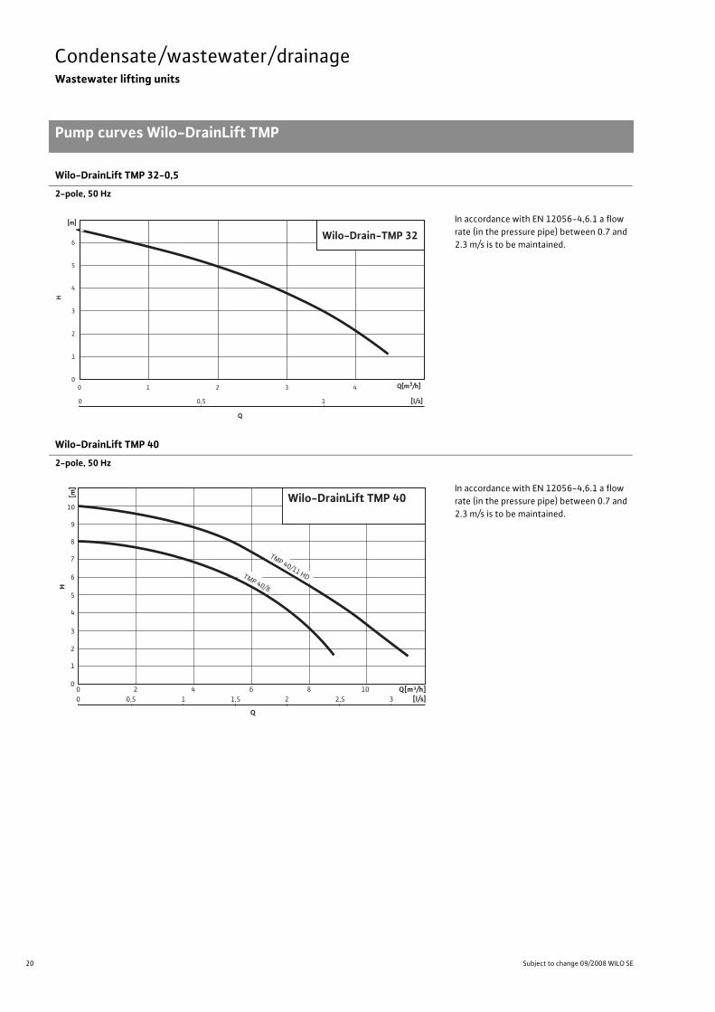
Pump curves Wilo-DrainLift TMP
Wilo-DrainLift TMP 32-0,5
2-pole, 50 Hz
In accordance with EN 12056-4,6.1 a flow rate (in the pressure pipe) between 0.7 and 2.3m/s is to be maintained.
Wilo-DrainLift TMP 40
2-pole, 50 Hz
In accordance with EN 12056-4,6.1 a flow rate (in the pressure pipe) between 0.7 and 2.3m/s is to be maintained.
Wilo-Drain-TMP 32
6
5
4
3
2
1
0 0 1 2 3 4 Q[m3/h]
H
[m]
0 0,5 1
Q
[l/s]
Wilo-DrainLift TMP 40
2
3
0
5
6
7
8
9
10
H
4
1
[m]
0 4 82 6 10
0 1 20,5 1,5 2,5 3
Q[m³/h]
TMP 40/8
TMP 40/11 HD
Q
[l/s]

21
Condensate/wastewater/drainageWastewater lifting units
Dimensions Wilo-DrainLift TMP
Wilo Catalogue C3 - 50 Hz - Wastewater and sewage lifting units, pumps stations
Cond
ensate/w
astewater/
draina
geSe
wag
e/faeces
Pumps
station
sElectrical
accessorie
sWilo
-Drain
Dimension drawings
Wilo-DrainLift TMP 32-0,5
1 = Inlet DN 402 = Inlet DN 40 (shower)3 = Pressure port G 1¼ (DN 32)4 = Ventilation DN 25
Wilo-DrainLift TMP 40/8 and TMP 40/11 HD
1 = Pressure pipe DN 402 = Ventilation DN 323 = Inlet DN 32 (washbasin)4 = Inlet DN 25 (washing machine)5 = Inlet DN 40 (shower)
A B
3
1
198
152
41
145204
2
3
1
300
A
B255,5511
4
268,
5
2
4
385
1
5
3 2
4
310 300
90
300
15078 75
510400
12575

22 Subject to change 09/2008 WILO SE
Condensate/wastewater/drainageWastewater lifting units
Installation example Wilo-DrainLift TMP
Installation example
Wilo-DrainLift TMP 32, 40
1: Pressure pipe 2: Ventilation pipe
� 1200
� 270
(TMP
40/8
)110
(TMP 32
)DN
40
1:50
1:50
2 1
Wilo-Drain TMP 32 - 0,5

23
Condensate/wastewater/drainageWastewater lifting units
Series description Wilo-DrainLift Box
Wilo Catalogue C3 - 50 Hz - Wastewater and sewage lifting units, pumps stations
Cond
ensate/w
astewater/
draina
geSe
wag
e/faeces
Pumps
station
sElectrical
accessorie
sWilo
-Drain
Wilo-DrainLift BoxWastewater lifting unit (concealed floor installation)
Type keye.g.: Wilo-DrainLift Box 32/8
Box Wastewater lifting unit (concealed floor installation)32 Nominal diameter of the pressure port (DN 32, � 40)8 Max. delivery head [m]
ApplicationFor concealed floor installation, can be used to drain
- Rooms at risk of flooding-Garage entrances- Basement stairways- Showers, washbasins, washing machines, dishwashers
DesignAutomatically switching lifting unit with built-in submersible pump and non-return valve. Ready for installation in concealed floor struc-tures. Flexible, due to two inlet options in DN 100 and a connection (DN 100) to a second tank.
Scope of deliveryPump ready for connection with attached float switch in impact-re-sistant plastic container for concealed floor installation. Completely ready for operation with pressure pipe and non-return valve already installed. Pump cable (5 m or 10 m long) with shock-proof plug fitted. Installation and operating instructions.

24 Subject to change 09/2008 WILO SE
Condensate/wastewater/drainageWastewater lifting units
Technical data Wilo-DrainLift Box
Wilo-DrainLift…
Box 32/8 Box 32/11 Box 40/10
Approved fluids
Domestic sewage without faeces • • •Domestic sewage containing faeces – – –
Washing machine soap and water mixture(without long-fibre constituents) • • •
Shower and bath water, unchlorinated • • •Charged condensate – – –
Electrical connection
Mains connection [V] 1~230 1~230 1~230
Power consumption P1 [kW] 0.45 0.75 0.94
Nominal motor power P2 [kW] 0.37 0.55 0.6
Nominal current [A] 2.1 3.6 4.4
Mains frequency [Hz] 50 50 50
Cable length from system to switchgear/plug [m] 10 10 5
Approved field of application
Operating mode S3 -25% S3 -25% S3 -25%
Max. switching frequency [1/h] 60 60 30
Max. permitted pressure in the pressure pipe [bar] 1.1 1.1 1.1
Fluid temperature, maximum [°C] 35 35 35
Fluid temperature [°C], for short periods 3 min. 90 90 –
Connections
Pressure port [mm] � 40 � 40 � 40
Inlet connection [mm] 100 100 100
Ventilation [mm] 100 100 100
Motor
Insulation class F F B
Protection class IP 67 IP 67 IP 67
Dimensions/weights
Gross volume [l] 85 85 85
Switching volume [l] 22 22 30
Weight [kg] 30 32 38
• = available or approved, - = not available or not approved

25
Condensate/wastewater/drainageWastewater lifting units
Pump curves Wilo-DrainLift Box
Wilo Catalogue C3 - 50 Hz - Wastewater and sewage lifting units, pumps stations
Cond
ensate/w
astewater/
draina
geSe
wag
e/faeces
Pumps
station
sElectrical
accessorie
sWilo
-Drain
Wilo-DrainLift Box
2-pole, 50 Hz
1 = DrainLift Box 32/82 = DrainLift Box 32/113 = DrainLift Box 40/10
In accordance with EN 12056-4,6.1 a flow rate (in the pressure pipe) between 0.7 and 2.3m/s is to be maintained.
Pump curves Wilo-DrainLift Box
[m3/h]0 2 4 6 8 10 12 14 16
H
[m]
0
4
8
6
10
12
2
Q
Wilo-DrainLift Box
32
1

26 Subject to change 09/2008 WILO SE
Condensate/wastewater/drainageWastewater lifting units
Dimensions Wilo-DrainLift Box
Dimension drawings
DrainLift Box 32 DrainLift Box 40Dimen-sions Wilo-DrainLift Box
Ø 500
445
760
Ø 40
Ø 50
Ø 295
350
720
110
110
100
DN100
DN100
DN100
100110
300
710
880
730
550
70
500
Ø 500
445
760
Ø 40
Ø 50
Ø 295
350
720
110
110
100
DN100
DN100
DN100
100110
300
710
880
730
550
70
500

Wilo-DrainLift XS-F.
Automatic sewage lifting unit.*For front wall installation.
Ideal for the guest bathroom in the basement.For new buildings, renovations
and modernisation.
The Wilo-DrainLift XS-F is the perfect solution for complete guest bathrooms underneath the drainage pipe level, e.g., in the basement. This automatic sewage lifting unit* is used for the disposal of sewage from wall-mounted toilets. Optionally, a wash stand, a showerand a bidet can be connected in the same room. The Wilo-DrainLift XS-F meets all requirementsfor a front wall installation and is thus ideally suited for new buildings, renovations andmodernisation. Flexible? We call this Pumpen Intelligenz.
www.wilo.com
* For limited use in accordance with EN 12050-3 and DIN 1986-100.

28 Subject to change 09/2008 WILO SE
Sewage/faecesSewage lifting units
Series overview Wilo-DrainLift KH, XS-F, S
12
Series: Wilo-DrainLift KH
>Small sewage lifting unit> Application:• For limited use (in direct connection behind a stand-alone toilet) with macerator for dis-posal of the sewage from an individual toilet in addition to a hand washbasin, a shower or a bidet.
Series: Wilo-DrainLift XS-F
>Small sewage lifting unit> Application:• For limited use (in direct connection to a wall-mounted toilet) for special installation in the front wall for the disposal of sewage from an individual toilet, in addition to a hand washbasin, a shower or a bidet.
Series: Wilo-DrainLift S
>Sewage lifting unit> Application:• Pumping of untreated sewage, which can-not be conveyed to the sewer system via natural slope.
• Drainage of individual rooms.
Q[m3/h]0 1 2 3
H[m
]
0
2
3
4
1
Wilo-DrainLiftKH 32-0,4
Q[m3/h]0 1 2 3 4 5 6 7 8
H[m
]
0
2
1
4
3
5
Wilo-DrainLift XS-F
0
2
4
H[m
]
0 5 10 15 20 25 30Q[m3/h]
Wilo-DrainLift S
29
Sewage/faecesSewage lifting units
Series overview Wilo-DrainLift KH, XS-F, S
Wilo Catalogue C3 - 50 Hz - Wastewater and sewage lifting units, pumps stations
Cond
ensate/w
astewater/
draina
geSe
wag
e/faeces
Pumps
station
sElectrical
accessorie
sWilo
-Drain
Series: Wilo-DrainLift KH
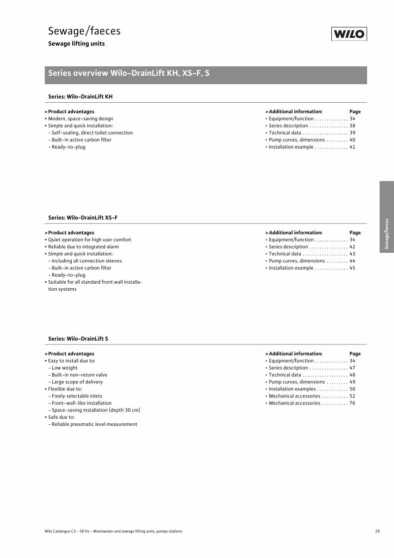
>Product advantages• Modern, space-saving design• Simple and quick installation:- Self-sealing, direct toilet connection- Built-in active carbon filter-Ready-to-plug
>Additional information: Page• Equipment/function . . . . . . . . . . . . . . 34• Series description . . . . . . . . . . . . . . . . 38• Technical data . . . . . . . . . . . . . . . . . . . 39• Pump curves, dimensions . . . . . . . . . 40• Installation example . . . . . . . . . . . . . . 41
Series: Wilo-DrainLift XS-F
>Product advantages• Quiet operation for high user comfort• Reliable due to integrated alarm• Simple and quick installation:- Including all connection sleeves- Built-in active carbon filter-Ready-to-plug
• Suitable for all standard front wall installa-tion systems
>Additional information: Page• Equipment/function . . . . . . . . . . . . . . 34• Series description . . . . . . . . . . . . . . . . 42• Technical data . . . . . . . . . . . . . . . . . . . 43• Pump curves, dimensions . . . . . . . . . 44• Installation example . . . . . . . . . . . . . . 45
Series: Wilo-DrainLift S
>Product advantages• Easy to install due to:- Low weight- Built-in non-return valve- Large scope of delivery
• Flexible due to:- Freely selectable inlets- Front-wall-like installation- Space-saving installation (depth 30 cm)
• Safe due to:-Reliable pneumatic level measurement
>Additional information: Page• Equipment/function . . . . . . . . . . . . . . 34• Series description . . . . . . . . . . . . . . . . 47• Technical data . . . . . . . . . . . . . . . . . . . 48• Pump curves, dimensions . . . . . . . . . 49• Installation examples . . . . . . . . . . . . . 50• Mechanical accessories . . . . . . . . . . . 52• Mechanical accessories . . . . . . . . . . . 76

30 Subject to change 09/2008 WILO SE
Sewage/faecesSewage lifting units
Series overview Wilo-DrainLift M, L, XL
Series: Wilo-DrainLift M 1/8
>Sewage lifting unit> Application:• Pumping of untreated sewage that cannot
be conveyed to the sewer system via natural slope.
• For the drainage of detached houses and non-public buildings
Series: Wilo-DrainLift M 2
>Sewage lifting unit> Application:• Pumping of untreated sewage, which can-not be conveyed to the sewer system via natural slope.
• For the drainage of detached houses and small blocks of buildings.
Series: Wilo-DrainLift L
>Sewage lifting unit> Application:• Pumping of untreated sewage, which can-not be conveyed to the sewer system via natural slope.
• For the drainage of multi-family houses and smaller properties (cafés, etc).
01
2
3
45
6
7
H[m
]
302520151050 Q[m³/h]
Wilo-DrainLift M 1/8
H[m
]
10 20 30 40 500 0
2
4
6
Wilo-DrainLift M2
Q[m3/h]
0 10 20 30 40 500
5
10
15
20
H[m
]
Wilo-DrainLift L
Q [m3/h]

31
Sewage/faecesSewage lifting units
Series overview Wilo-DrainLift M, L, XL
Wilo Catalogue C3 - 50 Hz - Wastewater and sewage lifting units, pumps stations
Cond
ensate/w
astewater/
draina
geSe
wag
e/faeces
Pumps
station
sElectrical
accessorie
sWilo
-Drain
Series: Wilo-DrainLift M 1/8
>Product advantages:• Easy to install due to:-Compact dimensions- Low weight - Large scope of delivery
• Flexible due to:- Freely selectable inlets
• Safe due to:- Integrated mains-independent alarm function - Integrated thermal motor protection-Additional potential-free contact
>Additional information: Page• Equipment/function . . . . . . . . . . . . . . 36• Series description . . . . . . . . . . . . . . . . 54• Technical data . . . . . . . . . . . . . . . . . . . 56• Pump curves . . . . . . . . . . . . . . . . . . . . 57• Dimensions . . . . . . . . . . . . . . . . . . . . . . 58• Inlet areas . . . . . . . . . . . . . . . . . . . . . . . 59• Installation examples . . . . . . . . . . . . . 62• Mechanical accessories . . . . . . . . . . . 76
Series: Wilo-DrainLift M 2
>Product advantages• Easy to install due to:- Low weight- Built-in non-return valve- Large scope of delivery
• Flexible due to:- Freely selectable inlets
• Safe due to:- Large tank volume- Integrated mains-independent alarm function
>Additional information: Page• Equipment/function . . . . . . . . . . . . . . 36• Series description . . . . . . . . . . . . . . . . 55• Technical data . . . . . . . . . . . . . . . . . . . 56• Pump curves . . . . . . . . . . . . . . . . . . . . 57• Dimensions . . . . . . . . . . . . . . . . . . . . . . 60• Inlet areas . . . . . . . . . . . . . . . . . . . . . . . 61• Mechanical accessories . . . . . . . . . . . 76
Series: Wilo-DrainLift L
>Product advantages• Easy to install due to:- Low weight- Built-in non-return valve- Large scope of delivery
• Flexible due to:- Freely selectable inlets-Wide performance range
• Safe due to:- Large tank volume-Mains-independent alarm function-Optional “-C” versions with individual fault signal and follow-up time-Additional potential-free contact
>Additional information: Page• Equipment/function . . . . . . . . . . . . . . 36• Series description . . . . . . . . . . . . . . . . 63• Technical data . . . . . . . . . . . . . . . . . . . 64• Pump curves . . . . . . . . . . . . . . . . . . . . 65• Dimensions . . . . . . . . . . . . . . . . . . . . . 66/68• Inlet areas . . . . . . . . . . . . . . . . . . . . . . . 6769• Installation examples . . . . . . . . . . . . . 70• Mechanical accessories . . . . . . . . . . . 76

32 Subject to change 09/2008 WILO SE
Sewage/faecesSewage lifting units
Series overview Wilo-DrainLift XXL, FTS
Series: Wilo-DrainLift XL
>Sewage lifting unit> Application:• Pumping of untreated sewage, which can-not be conveyed to the sewer system via natural slope.
• For the drainage of large properties (public houses, department stores etc.)
Series: Wilo-DrainLift XXL
>Sewage lifting unit> Application:• Elimination of untreated sewage, which cannot be conveyed to the sewer system via natural slope.
• For the drainage of large blocks of buildings (hotels, hospitals, etc.)
Series: Wilo-DrainLift FTS
>Sewage lifting unit> Application:• Pumping of untreated sewage, which cannot
be conveyed to the sewer system via natural slope.
• For the drainage of large blocks of buildings (hotels, hospitals, etc.)
0 10 20 30 40 500
5
10
15
20
H[m
]
Wilo-DrainLift XL
Q[m3/h]
Q[m3/h]0 20 40 80 10060
H [m
]
0
4
12
16
8
Wilo-DrainLift XXL
25
30
20
15
10
5
0
H[m
]
Q[m³/h]30 40 50 6020100
Wilo-DrainLift FTS

33
Sewage/faecesSewage lifting units
Series overview Wilo-DrainLift XXL, FTS
Wilo Catalogue C3 - 50 Hz - Wastewater and sewage lifting units, pumps stations
Cond
ensate/w
astewater/
draina
geSe
wag
e/faeces
Pumps
station
sElectrical
accessorie
sWilo
-Drain
Series: Wilo-DrainLift XL
>Product advantages• Large tank volume• Mains-independent alarm• Additional potential-free contact• Only one pressure outlet (integrated
Y-pipe)• Built-in non-return valve• Suitable for permanent operation (due to integrated sheath current cooling)
>Additional information: Page• Equipment/function . . . . . . . . . . . . . . 36• Series description . . . . . . . . . . . . . . . . 71• Technical data . . . . . . . . . . . . . . . . . . . 72• Pump curves . . . . . . . . . . . . . . . . . . . . 73• Dimensions . . . . . . . . . . . . . . . . . . . . . . 74• Installation examples . . . . . . . . . . . . . 75• Mechanical accessories . . . . . . . . . . . 76
Series: Wilo-DrainLift XXL
>Product advantages• Large tank volume• Low weight• Wide performance range• Suitable for permanent operation (due to integrated sheath current cooling)
>Additional information: Page• Equipment/function . . . . . . . . . . . . . . 36• Series description . . . . . . . . . . . . . . . . 77• Technical data . . . . . . . . . . . . . . . . . . . 78• Pump curves, dimensions . . . . . . . . . 80• Installation examples . . . . . . . . . . . . . 82• Mechanical accessories . . . . . . . . . . . 83
Series: Wilo-DrainLift FTS
>Product advantages• High efficiency, due to pumps with small free ball passage
• Large delivery heads• System non-susceptible to clogging, due to solids separation
• Large tank volume
>Additional information: Page• Equipment/function . . . . . . . . . . . . . . 36• Series description . . . . . . . . . . . . . . . . 85• Technical data . . . . . . . . . . . . . . . . . . . 86• Pump curves, dimensions . . . . . . . . . 88• System example . . . . . . . . . . . . . . . . . 89• Installation example . . . . . . . . . . . . . . 90

34 Subject to change 09/2008 WILO SE
Sewage/faecesSewage lifting units
Equipment/function Wilo-DrainLift KH, XS-F, S
Wilo-DrainLift…
KH 32-0,4 XS-F S 1/5
Sealing of pumps/motor
On fluid side: Mechanical seal – – •Oil barrier chamber – – •
Design
Pump position: Motor part outside the tank – – •Submersible pump, dry, external – – –
Submersible pump in the tank • • –
Inlet position freely selectable – – •Single-pump system • • •Double-pump system – – –
Single-channel impeller – – –
Vortex impeller • • •Macerator • – –
Materials
Motor housing Stainless steel 1.4301 (AISI 304) 1.4301 (AISI 304) 1.4404 (AISI 316L)
Cast iron – – –
Hydraulics Plastic PP-GF30 PP-GF30 PUR
Cast iron – – –
Tank Plastic ABS ABS PE
Equipment
Sheath current cooling – – –
Motor monitoring : Temperature (WSK) • • •Impermeability – – –
Level control: Float switch – – –
Pneumatic pressure sensor • • •Level sensor – – –
Alarm: Mains-independent – – –
Potential-free contact – • •Pump cable detachable – – •Ready-to-plug • • •Non-return valve • • •Inlet seal • • •Hole saw for inlet borehole – – •Hose connection for ventilation – • •
• = available, - = not available

35
Sewage/faecesSewage lifting units
Equipment/function Wilo-DrainLift KH, XS-F, S
Wilo Catalogue C3 - 50 Hz - Wastewater and sewage lifting units, pumps stations
Cond
ensate/w
astewater/
draina
geSe
wag
e/faeces
Pumps
station
sElectrical
accessorie
sWilo
-Drain
Equipment (continued)
Hose connection for diaphragm hand pump – – •Seal for suction pipe connection for diaphragm hand pump – – –
Kit for pressure pipe connection • • –
Fixation material • • •Soundproofing material – • •Switchgear – – –
Active carbon filter • • –
Wilo-DrainLift…
KH 32-0,4 XS-F S 1/5
• = available, - = not available
36 Subject to change 09/2008 WILO SE
Sewage/faecesSewage lifting units
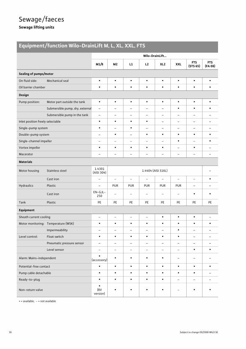
Equipment/function Wilo-DrainLift M, L, XL, XXL, FTS
Wilo-DrainLift…
M1/8 M2 L1 L2 XL2 XXL FTS (STS 65)
FTS (FA 08)
Sealing of pumps/motor
On fluid side: Mechanical seal • • • • • • • •Oil barrier chamber • • • • • • • •
Design
Pump position: Motor part outside the tank • • • • • • • •Submersible pump, dry, external – – – – – • • •Submersible pump in the tank – – – – – – – –
Inlet position freely selectable • • • • – – – –
Single-pump system • – • – – – – –
Double-pump system – • – • • • • •Single-channel impeller – – – – – • – •Vortex impeller • • • • • – • –
Macerator – – – – – – – –
Materials
Motor housing Stainless steel 1.4301 (AISI 304) 1.4404 (AISI 316L) –
Cast iron – – – – – – – •Hydraulics Plastic – PUR PUR PUR PUR PUR – –
Cast iron EN-GJL-250 – – – – – • •
Tank Plastic PE PE PE PE PE PE PE PE
Equipment
Sheath current cooling – – – – • • • –
Motor monitoring: Temperature (WSK) • • • • • • • •Impermeability – – – – – • – –
Level control: Float switch • • • • • • – –
Pneumatic pressure sensor – – – – – – – –
Level sensor – – – – – – • •
Alarm: Mains-independent •(accessory) • • • • – – –
Potential-free contact • • • • • • • •Pump cable detachable • • • • • • • –
Ready-to-plug • • • • • – – –
Non-return valve•
(RVversion)
• • • • – • •
• = available, - = not available

37
Sewage/faecesSewage lifting units
Equipment/function Wilo-DrainLift M, L, XL, XXL, FTS
Wilo Catalogue C3 - 50 Hz - Wastewater and sewage lifting units, pumps stations
Cond
ensate/w
astewater/
draina
geSe
wag
e/faeces
Pumps
station
sElectrical
accessorie
sWilo
-Drain
Equipment (continued)
Inlet seal • • • • – – • •Curve cutter for inlet borehole • • • • – – – –
Hose connection for ventilation • • • • • • – –
Hose connection for diaphragm hand pump • • • • • • – –
Seal for suction pipe connection for diaphragm hand pump • – – – – – – –
Kit for pressure pipe connection • • • • • • – –
Fixation material • • • • • • • •Soundproofing material • • • • – – – –
Switchgear • • • • • • • •Active carbon filter – – – – – – – –
Wilo-DrainLift…
M1/8 M2 L1 L2 XL2 XXL FTS (STS 65)
FTS (FA 08)
• = available, - = not available

38 Subject to change 09/2008 WILO SE
Sewage/faecesSewage lifting units
Series description Wilo-DrainLift KH
Wilo-DrainLift KHSmall sewage lifting unit (floor-mounted installation)
Type keye.g.: Wilo-DrainLift KH 32-0,4
KH Small lifting unit with macerator for sewage containing faeces32 Nominal diameter of the pressure port (DN 25/32)– 0,4 Nominal motor power [KW]
ApplicationSewage lifting unit ready for connection for limited use (in direct connection behind a stand-alone toilet) with macerator for the dis-posal of the sewage from an individual toilet in addition to a hand washbasin, a shower or a bidet, the wastewater/sewage of which cannot be conveyed to the sewer system via natural slope and/or for the disposal of wastewater that accumulates below the backflow level. DIN EN 12050-3 as well as DIN 1986-100 are to be complied with.We recommend using products of the Wilo-DrainLift S to XXL and FTS series when connecting several or different drainage fixtures.
DesignAutomatically operating small lifting unit with macerator, all switch-gears and control units required, built-in non-return valve, active carbon filter, flexible pressure port and connection options for one toilet, two additional drainage fixtures and one ventilation pipe.The DrainLift KH 32 small lifting unit is connected directly to one toi-let basin with a horizontal connection port. The connections for additional drainage fixtures and for the pressure pipe are at the back of the system and can be guide out either to the right or to the left. Odour-free exhaust ventilation into the installa-tion room is implemented by means of an integrated active carbon filter or a ventilation pipe over the roof.
Inlet connection:-DN 100 (direct connection via sealing collar)-2 inlets – DN 40 including blank cover and a non-return valve
Connection on pressure side:Pressure port hose angle DN 25/32 incl. non-return valve
Ventilation:Optionally integrated active carbon filter with overflow protection or connection of a separate ventilation pipe over the roof via self-seal-ing connecting sleeve (outside pipe � 25mm).
Scope of deliveryLifting unit ready for connection with macerator, active carbon filter, flexible pressure port and installation and operating instructions.
Max. pressure pipe lengths DN 32, for optimum operation, the first section of the pressure pipe should be positioned vertically and then the rest continued horizontally if possible (2 bends of 90° and a built-in non-return valve are taken into account).
4,020 m
25 m
30 m
35 m
40 m
50 m
45 m
3,5
3,0
2,5
2,0
1,5
1,0
0
H [m
]

39
Sewage/faecesSewage lifting units
Technical data Wilo-DrainLift KH
Wilo Catalogue C3 - 50 Hz - Wastewater and sewage lifting units, pumps stations
Cond
ensate/w
astewater/
draina
geSe
wag
e/faeces
Pumps
station
sElectrical
accessorie
sWilo
-Drain
Wilo-DrainLift KH 32-0,4
Approved fluids
Domestic sewage without faeces •Domestic sewage containing faeces •Washing machine soap and water mixture(without long-fibre constituents) –
Shower water, unchlorinated •
Electrical connection
Mains connection [V] 1~230
Power consumption P1 [kW] 0.45
Nominal current [A] 2.1
Mains frequency [Hz] 50
Cable length from system to switchgear/plug [m] 1.2
Approved field of application
Operating mode Intermittent operation S3 - 28%/36 sec. in acc. with DIN EN 60034-1
Max. switching frequency [1/h] 100
Activation level (measured from the floor) [mm] 70
Max. permitted pressure in the pressure pipe [bar] 0.7
Fluid temperature, maximum [°C] 35
Ambient temperature, maximum [°C] 35
Connections
Free ball passage [mm] 10
Pressure port [mm] DN 25/32
Inlet connection [mm] 2 x DN 40DN 100
Ventilation [mm] 25
Min. suction head (bottom to the middle of the inlet) [mm] 180
Motor
Insulation class F
Protection class IP 44
Dimensions/weights
Gross volume [l] 17
Switching volume [l] 2.6
Weight [kg] 7.8
• = available or approved, - = not available or not approved

40 Subject to change 09/2008 WILO SE
Sewage/faecesSewage lifting units
Pump curve, dimensions Wilo-DrainLift KH
Wilo-DrainLift KH 32-0,4
2-pole, 50 Hz
In accordance with EN 12056-4,6.1 a flow rate (in the pressure pipe) between 0.7 and 2.3m/s is to be maintained.
Dimension drawing
1 Toilet inlet DN 1002 Inlet DN 403 Pressure pipe connection4 Inlet DN 40 5 Ventilation
[m3/h]0 1 2 3
H
[m]
0
2
1
4
3
5
Q
Wilo-DrainLift KH 32-0,4
A B
3
21
5
198
152
41
145204
4
4
3
2
276,
5
A
B255,5511
5
268,
5
23,5

41
Sewage/faecesSewage lifting units
Installation example Wilo-DrainLift KH
Wilo Catalogue C3 - 50 Hz - Wastewater and sewage lifting units, pumps stations
Cond
ensate/w
astewater/
draina
geSe
wag
e/faeces
Pumps
station
sElectrical
accessorie
sWilo
-Drain
Installation example
* Please observe the information in the installation and operating instructions.
(*11
0)�
180
180
270� 120 0
DN
40
12
1:50DN
40
1:50
1: Pressure pipe2: Ventilation pipe (optional)

42 Subject to change 09/2008 WILO SE
Sewage/faecesSewage lifting units
Series description Wilo-DrainLift XS-F
Wilo-DrainLift XS-FSmall sewage lifting unit (front wall installation)
Type keye.g.: Wilo-DrainLift XS-F
XS Small lifting unit for sewage containing faecesF Front wall
ApplicationSewage lifting unit ready for connection for limited use (directly con-nected to a wall-mounted toilet) for special installation on the front wall. For the sewage disposal of an individual toilet, in addition to a hand washbasin, a shower or bidet, the wastewater/sewage of which can-not be discharged to the sewer system via the natural slope and/or for the disposal of wastewater/sewage that accumulates below the backflow level. DIN EN 12050-3 as well as DIN 1986-100 are to be observed. We recommend using products of the Wilo-DrainLift S to XXL and FTS series when connecting several or different drainage fixtures.
DesignAutomatically operating small lifting unit incl. all switchgear and con-trol units required, included non-return valve, active carbon filter, flexible pressure port and connection options for one toilet, two ad-ditional drainage fixtures and one ventilation pipe. The DrainLift XS-F small lifting unit is connected directly to a wall-mounted toilet. The direct toilet connection as well as connection options for addi-tional drainage fixtures are located on the long sides of the system. The two optional ventilation connection pieces are on the top of the tank. The fluid is discharged through a flexible pressure pipe which can be swivelled. The ventilation pipe is guided into the installation room via an includ-ed active carbon filter (odourless) or is guided over the roof. Any malfunction is indicated quickly by means of an integrated, mains-independent alarm signal. This signal can be passed on via an additional potential-free contact.Inlet connection:
-DN 100 (direct connection)-2 inlets, DN 50
Connection on pressure side:Pressure port incl. DN 32
Ventilation:-2 x DN 50
Optionally via included active carbon filter in the installation room or via pipe above the roof
Scope of deliveryLifting unit ready for connection incl. connection sleeves, non-return valve 1 ¼", adapter DN 32, active carbon filter, insertion screen for ventilation, accessories for the buoyancy safeguards, drain hose with sealing plugs, flexible pressure outlet which can be swivelled and in-stallation and operating instructions.
4,0
DN 32 DN 252 m
11 m
20 m
29 m
39 m
48 m
57 m
3,5
3,0
2,5
2,0
1,5
1,0
0,5
0
H[m
]
65 m
4,0
3 m
7 m
11 m
15 m
19 m
3,5
3,0
2,5
2,0
1,5
1,0
0,5
0
H[m
]
23 m
Max. pressure pipe lengths DN 32/DN 25, for optimum operation, the first section of the pressure pipe should be positioned vertically and then the rest continued horizontally if possible (2 bends of 90° and a built-in non-return valve are taken into account)

43
Sewage/faecesSewage lifting units
Technical data Wilo-DrainLift XS-F
Wilo Catalogue C3 - 50 Hz - Wastewater and sewage lifting units, pumps stations
Cond
ensate/w
astewater/
draina
geSe
wag
e/faeces
Pumps
station
sElectrical
accessorie
sWilo
-Drain
Wilo-DrainLift XS-F
Approved fluids
Domestic sewage without faeces •Domestic sewage containing faeces •Washing machine soap and water mixture(without long-fibre constituents) –
Shower water, unchlorinated •
Electrical connection
Mains connection [V] 1~230
Power consumption P1 [kW] 0.4
Nominal current [A] 1.8
Mains frequency [Hz] 50
Cable length from system to switchgear/plug [m] 1.5
Approved field of application
Operating mode Intermittent operation S3 - 30% (3 min operation/7 min pause)
Max. switching frequency [1/h] 100
Activation level (measured from the floor) [mm] 125
Max. permitted pressure in the pressure pipe [bar] 0.4
Fluid temperature, maximum [°C] 35
Ambient temperature, maximum [°C] 35
Connections
Free ball passage [mm] 25
Pressure port [mm] DN 32
Inlet connection [mm] 2 x DN 501 x DN 100
Ventilation [mm] 2 x DN 50
Min. suction head (bottom to the middle of the inlet) [mm] 220
Motor
Insulation class B
Protection class IP 44
Dimensions/weights
Gross volume [l] 7.9
Switching volume [l] 1.2
Weight [kg] 6.5
• = available or approved, - = not available or not approved
44 Subject to change 09/2008 WILO SE
Sewage/faecesSewage lifting units
Pump curves, dimensions Wilo-DrainLift XS-F
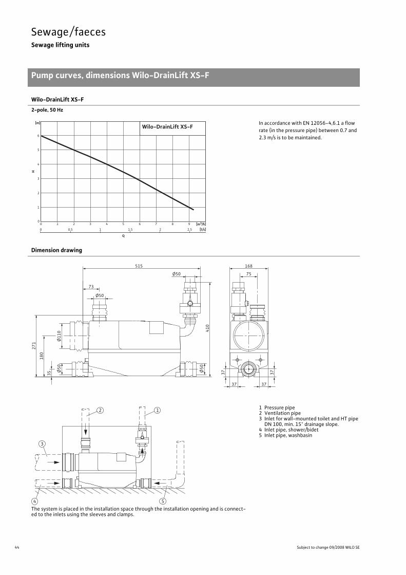
Wilo-DrainLift XS-F
2-pole, 50 Hz
In accordance with EN 12056-4,6.1 a flow rate (in the pressure pipe) between 0.7 and 2.3m/s is to be maintained.
Dimension drawing
The system is placed in the installation space through the installation opening and is connect-ed to the inlets using the sleeves and clamps.
1 Pressure pipe2 Ventilation pipe3 Inlet for wall-mounted toilet and HT pipe DN 100, min. 15° drainage slope.
4 Inlet pipe, shower/bidet5 Inlet pipe, washbasin
[m3/h]0 1 2 3 4 5 6 7 8 9
H
[m]
0
2
1
4
3
5
6
0 0,5 1 1,5 2,52
Q
[l/s]
Wilo-DrainLift XS-F
Ø1
10
Ø50
Ø50 75
168
73
515
Ø5
0
Ø5
0
37
37
37 37
35
18
0
27
1
41
0
4 5
3
12

45
Sewage/faecesSewage lifting units
Installation example Wilo-DrainLift XS-F
Wilo Catalogue C3 - 50 Hz - Wastewater and sewage lifting units, pumps stations
Cond
ensate/w
astewater/
draina
geSe
wag
e/faeces
Pumps
station
sElectrical
accessorie
sWilo
-Drain
Installation example
1 Vertical pressure pipe with non-return valve and loop to be guided over the lo-cally determined backflow level.
2 Pressure pipe, alternatively horizontally installed.
3 Ventilation via active carbon filter in the installation room, or alternatively above the roof
4 Inlet elbow for wall-mounted toilet and HT pipe DN 100, min. 15° drainage slope.
5 Back-up elbow, to be installed as close as possible to the system
Installation information, front wall installation
1 Inspection opening min. 500 x 4002 Use for ventilation with active carbon filter.
3 Ventilation screen (for changing the ac-tive carbon filter, only the ventilation screen has to be removed).
4 Ventilation pipe (HT) DN 50 connection sleeve DN 50
2%
15°
max. 350
min
. 1
80
Ø50
min
. 1
80
22
0> 2
20
5
2
3
1
4
A*
A*
min. 180 min. 550
min
. 3
7
max. 37
85
0
5
1
4
3
2

46 Subject to change 09/2008 WILO SE
Sewage/faecesSewage lifting units
Mechanical accessories Wilo-DrainLift XS-F
Mechanical accessories
Service hatch(frameless tile flap)Installation accessories for frameless tile flap, with concealed suspension technology and release safeguard. Suitable for sizes from 150x150mm up to max. 0.5m².
1 Magnetic angle2 Suspension bracket3 Suspension unit4 Metal strip5 Opening cord
Gate valve setConsisting of gate valve, designed as a cou-pling sleeve slider, female/female thread Rp 1¼" PN 16 RG,
and double nipple Male/male thread 1¼" x 1¼", for mounting the gate valve directly behind the non-re-turn valve (scope of delivery) at the pressure outlet.
2
3
1
4
5
54
1
2
3

47
Sewage/faecesSewage lifting units
Series description Wilo-DrainLift S
Wilo Catalogue C3 - 50 Hz - Wastewater and sewage lifting units, pumps stations
Cond
ensate/w
astewater/
draina
geSe
wag
e/faeces
Pumps
station
sElectrical
accessorie
sWilo
-Drain
Wilo-DrainLift SSewage lifting unit
Type keye.g.: Wilo-DrainLift S
Sewage lifting unit for front-wall-like installation, direct toilet connection or complete room drainage
ApplicationComplete sewage lifting unit ready for connection in accordance with DIN EN 12050-1.For pumping untreated sewage, which cannot be fed to the sewer system via the natural slope.Wilo-DrainLift S fulfils the specifications of DIN EN 12050-1 and DIN EN 12056.Minimum dimensions, combined with space-optimised installation area enable a wide range of different application options for:
- Retrofitting installation of showers, toilets, saunas, etc.- Installation of toilets in basement flats- Expansion/renovation of flats and buildings
Innovative combination of different installation options for sewage lifting units in a single system, e.g.:
-Direct toilet connection-Drainage of individual rooms- Front wall installation/recessed wall installation
Can be used in the following installation types:As conventional sewage lifting unit for connection of a wall-mounted or stand-alone toilet or for complete room drainage.Only minimum space required, due to the compact dimensions of the system.As a sewage lifting unit in conjunction with front wall installation/re-cessed wall installation, as an integrated part of a commercially avail-able front wall installation system, in recessed installation or in a pedestal profile.
Note:It must be possible to both install and remove the system after laying tiles. Observe installation instructions and accessories.
Design
Stainless steel motorProven construction in modern INOX & Composite design, including efficiency-optimised vortex impeller.
Carrying handle and securing strap (for buoyancy safeguard)Easy handling, firm fixation in accordance with applicable standards.
Inlet DN 40For additional inlets from washbasins, bathtubs, etc.
Freely selectable inletsFree areas along both long sides and one front side enable maximum connection flexibility (see illustration below). Observe the minimum suction head of the drainage fixtures.
Installation beadingFor commercially available front-wall installation systems.
Standard insulating matsPrevent structure-borne noise transmission.
Large inspection opening. Inclined collection space for deposit-free, reliable operation. Connection option for a DN 70 ventilation pipe and for a diaphragm hand pump.
Scope of deliverySewage lifting unit ready for connection, including switchgear/plug, non-return valve, intake seal DN 100, hole saw and installation and operating instructions.
Connection flexibility

48 Subject to change 09/2008 WILO SE
Sewage/faecesSewage lifting units
Technical data Wilo-DrainLift S
Wilo-DrainLift …
S 1/5
Approved fluids
Domestic sewage without faeces •Domestic sewage containing faeces •Washing machine soap and water mixture(without long-fibre constituents) •
Shower and bath water, unchlorinated •
Electrical connection
Power consumption P1 at 1~230 V, 50 Hz [kW] 1.25
Power consumption P1 at 3~400 V, 50 Hz [kW] 1.1
Nominal current with 1~230 V, 50 Hz [A] 6.8
Nominal current with 3~400 V, 50 Hz [A] 2.6
Mains frequency 50
Pump speed [1/min] 1450
Cable length from system to switchgear/plug [m] 4
Approved field of application
Operating mode S3 - 15%
Max. switching frequency [1/h] 30
Activation level (measured from the floor) [mm] 180
Max. permitted pressure in the pressure pipe [bar] 1.5
Fluid temperature, maximum [°C] 35
Fluid temperature, temporarily [°C] 60
Ambient temperature, maximum [°C] 40
Connections
Free ball passage [mm] 40
Pressure port [mm] DN 80
Inlet connection [mm] DN 40DN 100
Ventilation [mm] DN 70
Min. suction head (bottom to the middle of the inlet) [mm] 180
Motor
Insulation class H
Protection class (without switchgear) IP 67
Dimensions/weights
Gross volume [l] 45
Switching volume [l] 20
Weight [kg] 30
• = available or approved, – = not available or not approved

49
Sewage/faecesSewage lifting units
Pump curves, dimensions Wilo-DrainLift S
Wilo Catalogue C3 - 50 Hz - Wastewater and sewage lifting units, pumps stations
Cond
ensate/w
astewater/
draina
geSe
wag
e/faeces
Pumps
station
sElectrical
accessorie
sWilo
-Drain
Wilo-DrainLift S
4-pole, 50 Hz
In accordance with EN 12056-4,6.1 a flow rate (in the pressure pipe) between 0.7 and 2.3m/s is to be maintained.
Dimension drawing
1 Ventilation combination pipe 5 Inlet DN 402 Gate valve 6 Ventilation3 Flange piece 7 Pressure switch/alarm contact4 Motor
H
[m]
0
4
2
[m3/h]0 5 10 15 20 25 30
Q
QminDN 100
QminDN 80
Wilo-DrainLift S
7
DN80/100
DN80
3
2
1DN80
350
190
260
392
4
250
180 35
0
250
180 35
0
250
180
150 300799
150340
799637
65
337
300
245
150
100
19378

50 Subject to change 09/2008 WILO SE
Sewage/faecesSewage lifting units
Inlet areas, installation examples Wilo-DrainLift S
Freely selectable inlet areas
Installation examples
Direct toilet connection
60
45
45
290 45 45 45
80
45
60
45
45
250
180

51
Sewage/faecesSewage lifting units
Installation examples Wilo-DrainLift S
Wilo Catalogue C3 - 50 Hz - Wastewater and sewage lifting units, pumps stations
Cond
ensate/w
astewater/
draina
geSe
wag
e/faeces
Pumps
station
sElectrical
accessorie
sWilo
-Drain
Installation examples
Front-wall-like
1 Front wall frame
Diaphragm hand pump connection where necessary Stationary diaphragm hand pump connection
1 1 1
52 Subject to change 09/2008 WILO SE
Sewage/faecesSewage lifting units
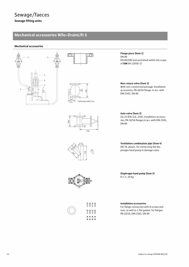
Mechanical accessories Wilo-DrainLift S
Mechanical accessories
Flange piece (item 1)DN 80DN 80/100 (not permitted within the scope of DIN EN 12050-1)
Non-return valve (item 2)With non-constricted passage, installation accessories, PN 10/16 flange, in acc. with DIN 2501, DN 80
Gate valve (item 3)GG 25 (EN-GJL-250), installation accesso-ries, PN 10/16 flanges in acc. with DIN 2501, DN 80
Ventilation combination pipe (item 4)DN 70, plastic, for connecting the dia-phragm hand pump in damage cases
Diaphragm hand pump (item 5)R 1 ½, 16 kg
Installation accessoriesFor flange connection with 8 screws and nuts, as well as 1 flat gasket, for flanges PN 10/16, DIN 2501, DN 80
5
1
3
2
5
4
240*
260
245 * Maß mit Z-Nr.* Dimension with Z no.
295
180
220180
Ø 75
°45

53
Sewage/faecesSewage lifting units
Mechanical accessories Wilo-DrainLift S
Wilo Catalogue C3 - 50 Hz - Wastewater and sewage lifting units, pumps stations
Cond
ensate/w
astewater/
draina
geSe
wag
e/faeces
Pumps
station
sElectrical
accessorie
sWilo
-Drain
Service hatch(frameless tile flap)Installation accessories for frameless tile flap, with concealed suspension technology and release safeguard. Suitable for sizes from 150x150mm up to max. 0.5m².
1 Magnetic angle2 Suspension bracket3 Suspension unit4 Metal strip5 Opening cord
Concealed distribution boxIncluding motor protection, acoustic alarm signal for Wilo-DrainLift S with bare cable end
Wilo KASSmall alarm switchgear with 70 dBA signal-ling tone, signal transmitter (electrode) with 3 m cable, self-charging power supply unit (battery backup approximately 5 h) in ISO plug housing (shock-proof). Protection class IP 30, 230 V~/9 V=; 1.5 VA
Mechanical accessories
2
3
1
4
5
54
1
2
3
Einbautiefe 85 mmInstallation depth 85mm

54 Subject to change 09/2008 WILO SE
Sewage/faecesSewage lifting units
Series description Wilo-DrainLift M1/8
Wilo-DrainLift M1/8Sewage lifting unit
Type keye.g.: Wilo-DrainLift M1/8 (1~)
Wilo-DrainLift M1/8 (1~) incl. non-return valve
DrainLift Sewage lifting unitM1 Single-pump system/8 Max. delivery head(1~) 1~: Single-phase version
3~: Three-phase versionincl. RV Version with non-return valve
(without data, version without non-return valve)
ApplicationSewage lifting unit for the drainage of residential houses and com-mercial buildings (e.g. public houses, department stores, etc.). Un-treated sewage that cannot be conveyed to the sewer system via natural slope and sewage from toilet systems that accumulates be-low the backflow level are, according to DIN EN 12056/DIN 1986-100, to be conveyed to the public sewer system by means of an au-tomatic lifting unit. Sewage containing mineral oils or explosive ad-mixtures must be guided through oil precipitators and/or petrol pre-cipitators; those containing fatty substances must go through grease traps and those with sand through grit chambers. In cases where the inflow to the lifting unit must not be interrupted during normal operation, one lifting unit must be equipped with a second pumping unit with the same capacity that is switched on au-tomatically when needed (DIN EN 12050-1 A1).
DesignFully submersible sewage lifting unit, ready for connection (flooding height: 2mWS, flooding time: 7 days) with a gastight and watertight collection tank that is equipped with buoyancy safeguards. Centrifu-gal pump with vortex impeller.
DrainLift M1/8:Single pump system with single-phase or three-phase motor for au-tomatic operation. Switchgear with shock-proof or CEE plug, poten-tial-free contact, integrated alarm and mains-independent, due to built-in rechargeable battery. RV version with non-return valve included in the scope of delivery.
Scope of deliverySewage lifting unit, ready for connection, including:
• Switchgear (mains-dependent alarm)• Inlet seal DN 100 (for pipe � 110mm)• Hole saw � 124 for inlet DN 100• PVC hose section � 50mm with clamps for inlet connection DN 50• Special lip seal for suction pipe connection of diaphragm hand pump DN 50
• Sleeve for ventilation connection DN 70• Fixation material • Sound absorption strip for insulation of structure-borne noise• Flange piece DN 80/100 with flat gasket, flexible hose section, hose clips, screws and nuts for connecting the DN 100 pressure pipe
• Non-return valve for RV version• Installation and operating instructions
OptionMains-independent alarm via separate 9 V rechargeable block bat-tery (accessory) that is to be plugged into the switchgear board

55
Sewage/faecesSewage lifting units
Series description Wilo-DrainLift M2
Wilo Catalogue C3 - 50 Hz - Wastewater and sewage lifting units, pumps stations
Cond
ensate/w
astewater/
draina
geSe
wag
e/faeces
Pumps
station
sElectrical
accessorie
sWilo
-Drain
Wilo-DrainLift M2Sewage lifting unit
Type keye.g.: Wilo-DrainLift M2 (3~)
DrainLift Sewage lifting unitM2 Double-pump system(3~) 1~: Single-phase version
3~: Three-phase version
ApplicationSewage lifting unit for the drainage of residential houses and com-mercial buildings (e.g. public houses, department stores, etc.). Un-treated sewage that cannot be conveyed to the sewer system via natural slope and sewage from toilet systems that accumulates be-low the backflow level are, according to DIN EN 12056/DIN 1986-100, to be conveyed to the public sewer system by means of an au-tomatic lifting unit. Sewage containing mineral oils or explosive ad-mixtures must be guided through oil precipitators and/or petrol pre-cipitators; those containing fatty substances must go through grease traps and those with sand through grit chambers. In cases where the inflow to the lifting unit must not be interrupted during normal operation, one lifting unit must be equipped with a second pumping unit with the same capacity that is switched on au-tomatically when needed (DIN EN 12050-1 A1).
DesignFully submersible sewage lifting unit, ready for connection (flooding height: 2mWS, flooding time: 7 days) with a gastight and watertight collection tank that is equipped with buoyancy safeguards. Centrifu-gal pump with vortex impeller.
DrainLift M2:Double pump system for automatic operation (with automatic duty cycling, standby and peak load operation). Due to the integrated double non-return valve, only one pressure pipe connection is re-quired. Switchgear with shock-proof or CEE plug, potential-free con-tact, integrated alarm and mains-independent, due to built-in re-chargeable battery.
Scope of deliverySewage lifting unit, ready for connection, including:
• Switchgear (mains-dependent alarm)• Inlet seal DN 100 (for pipe � 110mm)• Hole saw � 124 for inlet DN 100• PVC hose section � 50mm with clamps for inlet connection DN 50• DN 50 hose section with hose clips for suction pipe connection to di-aphragm hand pump or a DN 40 inlet
• Hose connection for diaphragm hand pump• Sleeve for ventilation connection DN 70• Fixation material • Sound absorption strip for insulation of structure-borne noise• DN 80/100 flange piece with flat gasket, flexible hose section, hose clips, screws and nuts for connecting the DN 100 pressure pipe
• Installation and operating instructions
OptionMains-independent alarm via separate 9 V rechargeable block bat-tery (accessory) that is to be plugged into the switchgear board.

56 Subject to change 09/2008 WILO SE
Sewage/faecesSewage lifting units
Technical data Wilo-DrainLift M1/8, M2
Wilo-DrainLift …
M1/8 M2
Approved fluids
Domestic sewage without faeces • •Domestic sewage containing faeces • •Washing machine soap and water mixture(without long-fibre constituents) • •
Shower and bath water, unchlorinated • •
Electrical connection
Power consumption P1 for 1~230 V, 50 Hz [kW] 1.28 1.6
Power consumption P1 for 3~400 V, 50 Hz [kW] 1.15 1.5
Nominal current with 1~230 V, 50 Hz [A] 5.7 7.5
Nominal current with 3~400 V, 50 Hz [A] 2.0 3.0
Mains frequency 50 50
Pump speed [1/min] 2900 1450
Cable length from system to switchgear/plug [m] 4 4
Approved field of application
Operating mode (for each pump) S3-15% S3 - 15%
Max. switching frequency [1/h] 45 60
Activation level (measured from the floor) [mm] 180 180
Max. permitted pressure in the pressure pipe [bar] 1.5 1.5
Fluid temperature, maximum [°C] 40 40
Fluid temperature, temporarily [°C] 60 60
Ambient temperature, maximum [°C] 40 40
Connections
Free ball passage [mm] 40 45
Pressure port [mm] DN 80 DN 65. DN 80
Inlet connection [mm] DN 40. DN 100. DN 150 DN 40. DN 100. DN 150
Ventilation [mm] DN 70 DN 70
Min. suction head (bottom to the middle of the inlet) [mm] 180 180
Motor
Insulation class H H
Protection class (without switchgear) IP 67 IP 67
Dimensions/weights
Gross volume [l] 62 130
Switching volume [l] 24 40
Weight [kg] 40 72
• = available or approved, – = not available or not approved

57
Sewage/faecesSewage lifting units
Pump curves Wilo-DrainLift M
Wilo Catalogue C3 - 50 Hz - Wastewater and sewage lifting units, pumps stations
Cond
ensate/w
astewater/
draina
geSe
wag
e/faeces
Pumps
station
sElectrical
accessorie
sWilo
-Drain
Wilo-DrainLift M1/8
2-pole, 50 Hz
In accordance with EN 12056-4,6.1 a flow rate (in the pressure pipe) between 0.7 and 2.3m/s is to be maintained.
Wilo-DrainLift M2
4-pole, 50 Hz
In accordance with EN 12056-4,6.1 a flow rate (in the pressure pipe) between 0.7 and 2.3m/s is to be maintained.
00
1
2
3
4
5
6
7
8
5 10 15 20 25 30 35 [m³/h]
[m]
H
Q
Wilo-DrainLift M 1/8QminDN 100
QminDN 80
[m3/h] 0 10 20 30 40 50
Q
H
[m]
0
4
6
2
Wilo-DrainLift M 2QminDN 100
Qmin DN 80

58 Subject to change 09/2008 WILO SE
Sewage/faecesSewage lifting units
Dimensions Wilo-DrainLift M1/8
Dimension drawing
Wilo-DrainLift M1/8
550
600
70
70
25
5
58
0
23
0
15
0
13
0
29
0
50
Ø804xM16Ø16070
225
DN50
DN50
DN70
50
5
40
5
16
2
14
7
35
48
0
50
50

59
Sewage/faecesSewage lifting units
Inlet areas Wilo-DrainLift M1/8
Wilo Catalogue C3 - 50 Hz - Wastewater and sewage lifting units, pumps stations
Cond
ensate/w
astewater/
draina
geSe
wag
e/faeces
Pumps
station
sElectrical
accessorie
sWilo
-Drain
Freely selectable inlet areas
Wilo-DrainLift M1/8
82 157,5
85
26
5
145 378
85
18
2
26
5
250
50
50
50
19
8
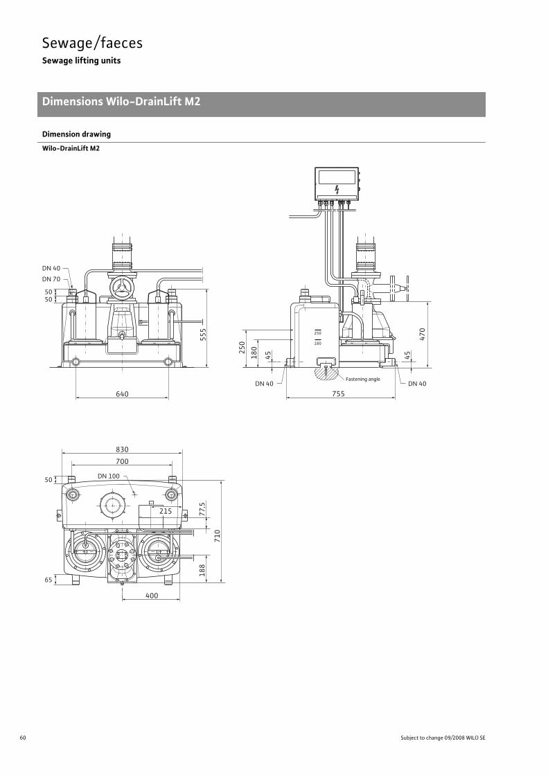
60 Subject to change 09/2008 WILO SE
Sewage/faecesSewage lifting units
Dimensions Wilo-DrainLift M2
Dimension drawing
Wilo-DrainLift M2
250
180
250
180
45
755
470
50
DN 40
DN 40
DN 100
DN 40
DN 70
50
50
65
640
400
700
215
830
45
555
710
188
77,5
Fastening angle

61
Sewage/faecesSewage lifting units
Inlet areas Wilo-DrainLift M2
Wilo Catalogue C3 - 50 Hz - Wastewater and sewage lifting units, pumps stations
Cond
ensate/w
astewater/
draina
geSe
wag
e/faeces
Pumps
station
sElectrical
accessorie
sWilo
-Drain
Freely selectable inlet areas
Wilo-DrainLift M2
85
15 164
30
5
15164
243
85
30
5
15
2
1523515 235
30
58
5
250
180
250
180
250
180

62 Subject to change 09/2008 WILO SE
Sewage/faecesSewage lifting units
Installation example Wilo-DrainLift M1/8
Installation example Wilo-DrainLift M1/8
Wilo-DrainLift M1/8
1 Ventilation pipe (over roof)2 Pressure pipe3 Inlet 4 Gate valve for feed line5 Fitting support for weight
relief6 Gate valve for pressure pipe7 Non-return valve 8 Drainage pipe tank 9 Drainage pipe pump sump 10 Drainage pump11 way valve12 Diaphragm hand pump13 Switchgear EC-Drain LS
EC-D
rain
LS
13
12
10
98765
3
4
2
1
11
Backflow level (generally upper street edge)

63
Sewage/faecesSewage lifting units
Series description Wilo-DrainLift L
Wilo Catalogue C3 - 50 Hz - Wastewater and sewage lifting units, pumps stations
Cond
ensate/w
astewater/
draina
geSe
wag
e/faeces
Pumps
station
sElectrical
accessorie
sWilo
-Drain
Wilo-DrainLift LSewage lifting unit
Type keye.g.: Wilo-DrainLift L1/25 (3~)
DrainLift Sewage lifting unitL1 L1 = Single-pump system
L2 = Double-pump system/25 Max. delivery head [m](3~) 3~: Three-phase version
ApplicationSewage lifting unit for drainage of residential houses and commercial buildings (e.g. public houses, department stores, etc.). Untreated sewage that cannot be conveyed to the sewer system via natural slope and sewage from toilet systems that accumulates below the backflow level are, according to DIN EN 12056/DIN 1986-100, to be conveyed to the public sewer system by means of an automatic lift-ing unit. Sewage containing mineral oils or explosive admixtures must be guided through oil precipitators and/or petrol precipitators; those containing fatty substances must go through grease traps and those with sand through grit chambers. In cases where the inflow to the lifting unit must not be interrupted during normal operation, one lifting unit must be equipped with a second pumping unit with the same capacity that is switched on au-tomatically when needed (DIN EN 12050-1 A1).
DesignFully submersible sewage lifting unit, ready for connection (flooding height: 2mWS, flooding time: 7 days) with a gastight and watertight collection tank that is equipped with buoyancy safeguards. Centrifu-gal pump with vortex impeller.
DrainLift L1:Single pump system with single-phase or three-phase motor for au-tomatic operation. Switchgear with shock-proof or CEE plug, poten-tial-free contact, integrated alarm and mains-independent, due to built-in rechargeable battery.
DrainLift L2:Double pump system for automatic operation (with automatic duty cycling, standby and peak load operation). Due to the integrated double non-return valve, only one pressure pipe connection is re-quired. Switchgear with shock-proof or CEE plug, potential-free con-tact, integrated alarm and mains-independent, due to built-in re-chargeable battery.
OptionDrainLift L1-C, L2-C version: Switchgear with individual fault signal and adjustable follow-up time.
Scope of deliverySewage lifting unit, ready for connection, including:
• Switchgear (mains-dependent alarm)• Inlet seal DN 100 (for pipe � 110mm)• Hole saw � 124 for inlet DN 100• PVC hose section � 50mm with clamps for inlet connection DN 50• DN 50 hose section with hose clips for suction pipe connection to diaphragm hand pump or a DN 40 inlet
• Hose connection for diaphragm hand pump• Sleeve for ventilation connection DN 70• Fixation material • Sound absorption strip for insulation of structure-borne noise• DN 80/100 flange piece with flat gasket, flexible hose section, hose clips, screws and nuts for connecting the DN 100 pressure pipe
• Installation and operating instructions
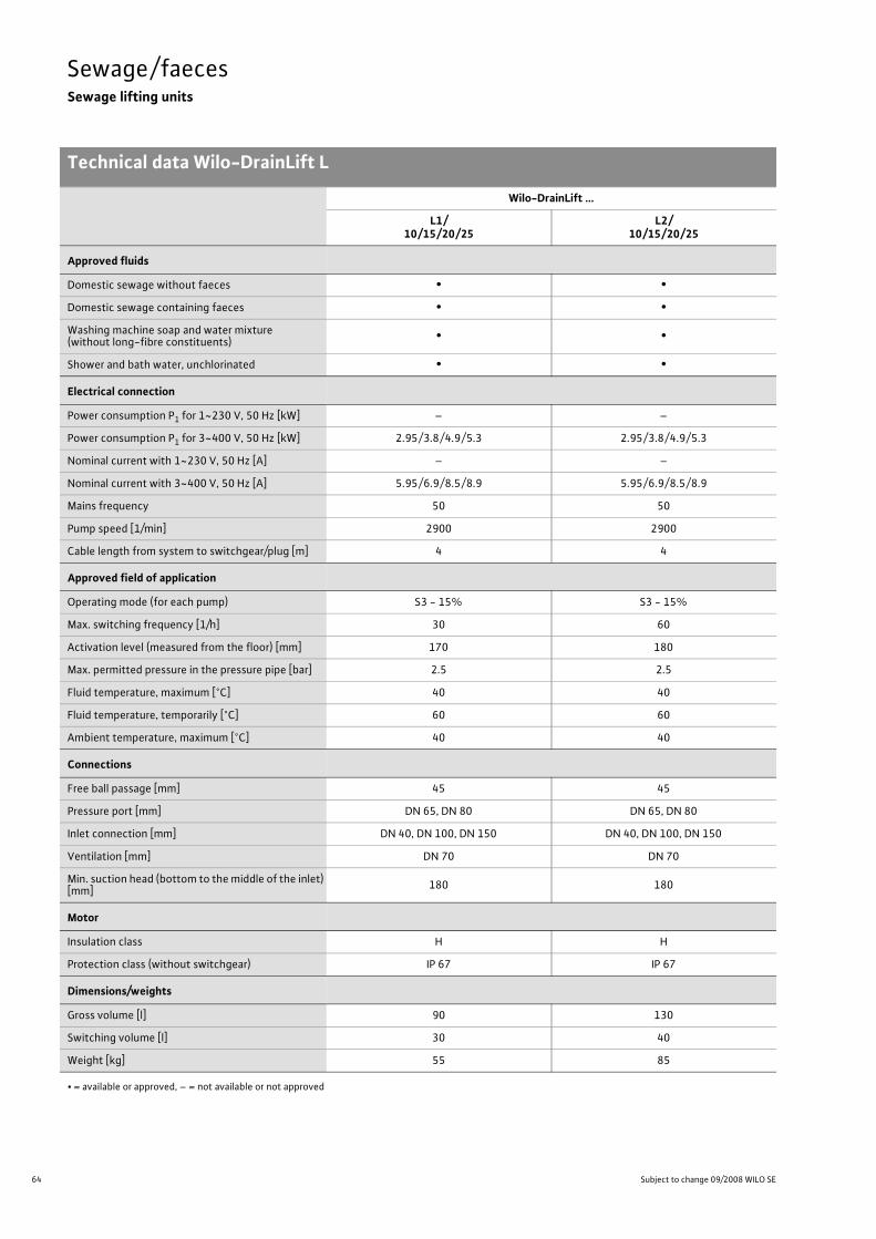
64 Subject to change 09/2008 WILO SE
Sewage/faecesSewage lifting units
Technical data Wilo-DrainLift L
Wilo-DrainLift …
L1/10/15/20/25
L2/10/15/20/25
Approved fluids
Domestic sewage without faeces • •Domestic sewage containing faeces • •Washing machine soap and water mixture(without long-fibre constituents) • •
Shower and bath water, unchlorinated • •
Electrical connection
Power consumption P1 for 1~230 V, 50 Hz [kW] – –
Power consumption P1 for 3~400 V, 50 Hz [kW] 2.95/3.8/4.9/5.3 2.95/3.8/4.9/5.3
Nominal current with 1~230 V, 50 Hz [A] – –
Nominal current with 3~400 V, 50 Hz [A] 5.95/6.9/8.5/8.9 5.95/6.9/8.5/8.9
Mains frequency 50 50
Pump speed [1/min] 2900 2900
Cable length from system to switchgear/plug [m] 4 4
Approved field of application
Operating mode (for each pump) S3 - 15% S3 - 15%
Max. switching frequency [1/h] 30 60
Activation level (measured from the floor) [mm] 170 180
Max. permitted pressure in the pressure pipe [bar] 2.5 2.5
Fluid temperature, maximum [°C] 40 40
Fluid temperature, temporarily [°C] 60 60
Ambient temperature, maximum [°C] 40 40
Connections
Free ball passage [mm] 45 45
Pressure port [mm] DN 65, DN 80 DN 65, DN 80
Inlet connection [mm] DN 40, DN 100, DN 150 DN 40, DN 100, DN 150
Ventilation [mm] DN 70 DN 70
Min. suction head (bottom to the middle of the inlet) [mm] 180 180
Motor
Insulation class H H
Protection class (without switchgear) IP 67 IP 67
Dimensions/weights
Gross volume [l] 90 130
Switching volume [l] 30 40
Weight [kg] 55 85
• = available or approved, – = not available or not approved

65
Sewage/faecesSewage lifting units
Pump curves Wilo-DrainLift L
Wilo Catalogue C3 - 50 Hz - Wastewater and sewage lifting units, pumps stations
Cond
ensate/w
astewater/
draina
geSe
wag
e/faeces
Pumps
station
sElectrical
accessorie
sWilo
-Drain
Wilo-DrainLift L
2-pole, 50 Hz
1 = DrainLift L 1/10 and L 2/102 = DrainLift L 1/15 and L 2/153 = DrainLift L 1/20 and L 2/204 = DrainLift L 1/25 and L 2/25
In accordance with EN 12056-4,6.1 a flow rate (in the pressure pipe) between 0.7 and 2.3m/s is to be maintained.
0
5
0 10 20 30 40 50 60
20
15
10
1
2
3
4
Wilo-DrainLift L
[m3/h]
Q
H
[m]QminDN 100
QminDN 80

66 Subject to change 09/2008 WILO SE
Sewage/faecesSewage lifting units
Dimensions Wilo-DrainLift L1
Dimension drawing
Wilo-DrainLift L1
5055
77
174
715
192,5
630
504
200
565
250
180
45
45
DN40
DN40770
630
250
180
5050
400
555
DN40DN70
Fastening angle

67
Sewage/faecesSewage lifting units
Inlet areas Wilo-DrainLift L1
Wilo Catalogue C3 - 50 Hz - Wastewater and sewage lifting units, pumps stations
Cond
ensate/w
astewater/
draina
geSe
wag
e/faeces
Pumps
station
sElectrical
accessorie
sWilo
-Drain
Freely selectable inlet areas
Wilo-DrainLift L1
174
25318515 15185
15
230
58
5
85
30
5
15
85
30
5
15185
250
180
250
180
250
180

68 Subject to change 09/2008 WILO SE
Sewage/faecesSewage lifting units
Dimensions Wilo-DrainLift L2
Dimension drawing
DrainLift L2
5065
715
193
830
700
400
5050
640
555
DN40DN70
565
250
180
45
45
DN40
DN40 755
630
180
250
Fastening angle

69
Sewage/faecesSewage lifting units
Inlet areas Wilo-DrainLift L2
Wilo Catalogue C3 - 50 Hz - Wastewater and sewage lifting units, pumps stations
Cond
ensate/w
astewater/
draina
geSe
wag
e/faeces
Pumps
station
sElectrical
accessorie
sWilo
-Drain
Freely selectable inlet areas
Wilo-DrainLift L2
85
15 164
30
5
15164
243
85
30
5
15
2
1523515 235
30
58
5
250
180
250
180
250
180

70 Subject to change 09/2008 WILO SE
Sewage/faecesSewage lifting units
Installation examples Wilo-DrainLift L
Installation examples
1 Gate valve DN 100 or DN 150(accessories)
2 Flange piece DN 100 orDN 150 with hose (accessories)
3 Flange piece DN 80/1004 Non-return valve (built into the pres-
sure port)5 Gate valve DN 80 (accessory)6 DrainLift L switchgear7 Diaphragm hand pump (accessory)8 3-way cock (accessory)9 Non-return valve (accessory)10 Drainage pump (Twister) 11 Ventilation connection (DN 70)12 Fitting support for weight relief
1
11
2
3 5
4
8
7
6
9
1012
Backflow level (generally upper street edge)
180 250

71
Sewage/faecesSewage lifting units
Series description Wilo-DrainLift XL
Wilo Catalogue C3 - 50 Hz - Wastewater and sewage lifting units, pumps stations
Cond
ensate/w
astewater/
draina
geSe
wag
e/faeces
Pumps
station
sElectrical
accessorie
sWilo
-Drain
Wilo-DrainLift XLSewage lifting unit
Type keye.g.: Wilo-DrainLift XL 2/25 (3~)
DrainLift Sewage lifting unitXL2 Double-pump system/25 Max. delivery head [m](3~) 3~: Three-phase version
ApplicationSewage lifting unit for the drainage of residential houses and com-mercial buildings (e.g. public houses, department stores, etc.). Un-treated sewage that cannot be conveyed to the sewer system via natural slope and sewage from toilet systems that accumulates be-low the backflow level are, according to DIN EN 12056/DIN 1986-100, to be conveyed to the public sewer system by means of an automatic lifting unit. Sewage containing mineral oils or explosive admixtures must be guided through oil precipitators and/or petrol precipitators; those containing fatty substances must go through grease traps and those with sand through grit chambers. In cases where the inflow to the lifting unit must not be interrupted during normal operation, one lifting unit must be equipped with a second pumping unit with the same capacity that is switched on automatically when needed (DIN EN 12050-1 A1).
DesignFully submersible sewage lifting unit, ready for connection (flooding height: 2mWS, flooding time: 7 days) with a gastight and watertight collection tank that is equipped with buoyancy safeguards. Centrifu-gal pump with vortex impeller.
Double pump system for automatic operation (with automatic duty cycling, standby and peak load operation). Due to the integrated double non-return valve, only one pressure pipe connection is re-quired. Switchgear with shock-proof or CEE plug, potential-free con-tact, integrated alarm and mains-independent, due to built-in re-chargeable battery. Pumps with integrated sheath current cooling.
Scope of deliverySewage lifting unit, ready for connection, including:
• Switchgear (mains-dependent alarm)• DN 50 hose section with hose clips for suction pipe connection to diaphragm hand pump or a DN 40 inlet
• Sleeve for ventilation connection DN 70• Fixation material • Flange piece DN 80/100 with flat gasket, flexible hose section, hose clips, screws and nuts for connecting the DN 100 pressure pipe
• Installation and operating instructions

72 Subject to change 09/2008 WILO SE
Sewage/faecesSewage lifting units
Technical data Wilo-DrainLift XL
Wilo-DrainLift XL10/15/20/25
Approved fluids
Domestic sewage without faeces •Domestic sewage containing faeces •Washing machine soap and water mixture(without long-fibre constituents) •
Shower and bath water, unchlorinated •
Electrical connection
Power consumption P1 for 1~230 V, 50 Hz [kW] –
Power consumption P1 for 3~400 V, 50 Hz [kW] 2.95/3.8/4.9/5.3
Nominal current with 1~230 V, 50 Hz [A] –
Nominal current with 3~400 V, 50 Hz [A] 5.95/6.9/8.5/8.9
Mains frequency 50
Pump speed [1/min] 2900
Cable length from system to switchgear/plug [m] 4
Approved field of application
Operating mode (for each pump) S1S3 - 60%
Max. switching frequency [1/h] 60
Activation level (measured from the floor) [mm] 650
Max. permitted pressure in the pressure pipe [bar] 2.5
Fluid temperature, maximum [°C] 40
Fluid temperature, temporarily [°C] 60
Ambient temperature, maximum [°C] 40
Connections
Free ball passage [mm] 45
Pressure port [mm] DN 65DN 80
Inlet connection [mm] DN 100DN 150
Ventilation [mm] DN 70
Min. suction head (bottom to the middle of the inlet) [mm] 700
Motor
Insulation class H
Protection class (without switchgear) IP 67
Dimensions/weights
Gross volume [l] 440
Switching volume [l] 220
Weight [kg] 135
• = available or approved, – = not available or not approved

73
Sewage/faecesSewage lifting units
Pump curve Wilo-DrainLift XL
Wilo Catalogue C3 - 50 Hz - Wastewater and sewage lifting units, pumps stations
Cond
ensate/w
astewater/
draina
geSe
wag
e/faeces
Pumps
station
sElectrical
accessorie
sWilo
-Drain
Wilo-DrainLift XL
2-pole, 50 Hz
1 = DrainLift XL 2/102 = DrainLift XL 2/15 3 = DrainLift XL 2/20 4 = DrainLift XL 2/25
In accordance with EN 12056-4,6.1 a flow rate (in the pressure pipe) between 0.7 and 2.3m/s is to be maintained.
0
5
0 10 20 30 40 50 60
20
15
10
Wilo-DrainLift XL
4
32
1
[m3/h]
Q
H
[m]QminDN 100
QminDN 80

74 Subject to change 09/2008 WILO SE
Sewage/faecesSewage lifting units
Dimensions Wilo-DrainLift XL
Dimension drawing
5050
680
840
Ø 10
Ø 1
60
1000
900
700
575
50
100
Ø 10 DN 40460
640
640
70
975
975 11
00
990
193
DN 40
DN 70

75
Sewage/faecesSewage lifting units
Installation example Wilo-DrainLift XL
Wilo Catalogue C3 - 50 Hz - Wastewater and sewage lifting units, pumps stations
Cond
ensate/w
astewater/
draina
geSe
wag
e/faeces
Pumps
station
sElectrical
accessorie
sWilo
-Drain
Installation example
1 Gate valve DN 100 or DN 150(accessories)
2 Flange piece DN 100 or DN 150 with hose (accessories)
3 Flange piece DN 80/1004 Non-return valve (built into the pres-
sure port)5 Gate valve DN 80 (accessory)6 Switchgear DrainLift XL7 Diaphragm hand pump (accessory)8 3-way cock (accessory)9 Non-return valve (accessory)10 Drainage pump (e.g. Twister)11 Ventilation connection (DN 70)12 Fitting support for weight relief1
3
5
4
6
10
9
8
7
2
11
12
22
Backflow level (generally upper street edge)

76 Subject to change 09/2008 WILO SE
Sewage/faecesSewage lifting units
Mechanical accessories Wilo-DrainLift S, M, L, XL
Connection accessories
Wilo-DrainLift…
S M L XL
Inlet connection Gate valve * (item 1)
DN 100DN 100
or DN 150
DN L [mm] D [mm]
100 190 220
150 210 285
Flange piece with hose and hose clips * (item 2)
2x DN 100
2x DN 100or
2x DN 150
DN L [mm]
100 190
150 210
Pressure sideconnection
Non-return valve *(item 4)
integratedDN H [mm] D [mm]
80 155 260
Gate valve * (item 5)
DN 80 DN 80 DN 80 DN 80
DN L [mm] D [mm]
80 180 220
Flange piece with hose and hose clips * (item 3)
DN 80 80/100 integratedDN L [mm]
80 180
100 190
Other connec-tions/accessories
Diaphragm hand pump R 1 ½ (item 7)
• • • •
3-way cock (item 8)
– – – –
* Required for installation in accordance with standards/recommendations in force• = available or approved, – = not available or not approved
L
DDN
L
DN
H
L
L
DDN
L
DN
R11/2
246
378500
R11/2

77
Sewage/faecesSewage lifting units
Series description Wilo-DrainLift XXL
Wilo Catalogue C3 - 50 Hz - Wastewater and sewage lifting units, pumps stations
Cond
ensate/w
astewater/
draina
geSe
wag
e/faeces
Pumps
station
sElectrical
accessorie
sWilo
-Drain
Wilo-DrainLift XXLSewage lifting unit
Type keye.g.: Wilo-DrainLift XXL 1080-2/8,4
XXL Sewage lifting unit for large buildings 10(8) Pressure port DN 100(80)80 Total volume 800 l
40 = Total volume 400 l2 Double-pump system8,4 Power P2 per pump [kW]
ApplicationSewage lifting unit for the drainage of residential houses and com-mercial buildings (e.g. public houses, department stores, etc.). Un-treated sewage that cannot be conveyed to the sewer system via natural slope and sewage from toilet systems that accumulates be-low the backflow level are, according to DIN EN 12056/DIN 1986-100, to be conveyed to the public sewer system by means of an au-tomatic lifting unit. Sewage containing mineral oils or explosive ad-mixtures must be guided through oil precipitators and/or petrol pre-cipitators; those containing fatty substances must go through grease traps and those with sand through grit chambers.
DesignFully submersible compact unit ready for connection (flooding height: 2mWS, flooding time: 7 days), with one or two gastight and watertight collection tanks.Equipped with two sewage pumps of the Wilo-Drain TP 80 or TP 100 series (material: Inox and composite). Easy handling due to the low overall weight of the system, e.g. double system with TP 80 pump only 160 kg (heaviest individual weight: pump with 62 kg). Optimal tank drainage due to deep extraction by suction.Attention: The switchgear is not submersible and must therefore be arranged in such a way that it is safe from flooding.
Scope of delivery-Microprocessor-controlled switchgear with automatic duty cycling, standby and peak load operation, potential-free contacts and signal lamps for operation and malfunctions of each pump.
- Flexible hose connection for ventilation DN 70.- Flexible hose connection for connecting a diaphragm hand pump.
Kit for connecting the tank to a pump (including ventilation flange with hose).
- (See also “Equipment/function” table)

78 Subject to change 09/2008 WILO SE
Sewage/faecesSewage lifting units
Technical data Wilo-DrainLift XXL
Wilo-DrainLift XXL…
840-
2/1,
788
0-2/1,
7
840-
2/2,1
880-
2/2,1
1040
-2/3
,910
80-2
/3,9
1040
-2/5
,210
80-2
/5,2
1040
-2/7
,010
80-2
/7,0
1040
-2/8
,410
80-2
/8,4
Approved fluids
Domestic sewage without faeces • • • • • •Domestic sewage containing faeces • • • • • •Washing machine soap and water mixture(without long-fibre constituents) • • • • • •
Shower and bath water, unchlorinated • • • • • •
Electrical connection
Mains connection [V] 3~400 3~400 3~400 3~400 3~400 3~400
Power consumption P1 [kW] 2.3 2.7 4.4 6.2 8.4 10.0
Nominal motor power P2 [kW] 1.7 2.1 3.9 5.2 7.0 8.4
Nominal current [A] 6.7 7.1 10.5 12.8 15.6 18.1
Mains frequency 50 50 50 50 50 50
Pump speed [1/min] 1450 1450 1450 1450 1450 1450
Cable length from system to switchgear/plug [m] 10 10 10 10 10 10
Approved field of application
Operating mode S1. S3 S1. S3 S1. S3 S1. S3 S1. S3 S1. S3
Max. switching frequency [1/h] 60 60 60 60 60 60
Activation level (measured from the floor) [mm] 560 560 560 560 560 560
Max. permitted pressure in the pressure pipe [bar] 2.5 2.5 2.5 2.5 2.5 2.5
Fluid temperature, maximum [°C] 40 40 40 40 40 40
Fluid temperature, temporarily [°C] 65 65 65 65 65 65
Ambient temperature, maximum [°C] 40 40 40 40 40 40
Connections
Free ball passage [mm] 78 78 95 95 95 95
Pressure port [mm] DN 80 DN 80 DN 100 DN 100 DN 100 DN 100
Inlet connection [mm] 3 x DN 100/1501 x DN 100
Ventilation [mm] 70 70 70 70 70 70
Min. suction head (bottom to the middle of the inlet) [mm] 700 700 700 700 700 700
Motor
Insulation class F F F F F F
Protection class (without switchgear) IP 68 IP 68 IP 68 IP 68 IP 68 IP 68
• = available or approved, – = not available or not approved

79
Sewage/faecesSewage lifting units
Technical data Wilo-DrainLift XXL
Wilo Catalogue C3 - 50 Hz - Wastewater and sewage lifting units, pumps stations
Cond
ensate/w
astewater/
draina
geSe
wag
e/faeces
Pumps
station
sElectrical
accessorie
sWilo
-Drain
Dimensions/weights
Gross volume [l] 400/800 400/800 400/800 400/800 400/800 400/800
Switching volume [l] 200/400 200/400 200/400 200/400 200/400 200/400
Tank volume [l] 400/2 x 400 400/2 x 400 400/2 x 400 400/2 x 400 400/2 x 400 400/2 x 400
Weight [kg] 160/195 160/195 195/230 195/230 195/230 195/230
Wilo-DrainLift XXL…
840-
2/1,
788
0-2/1,
7
840-
2/2,1
880-
2/2,1
1040
-2/3
,910
80-2
/3,9
1040
-2/5
,210
80-2
/5,2
1040
-2/7
,010
80-2
/7,0
1040
-2/8
,410
80-2
/8,4
• = available or approved, – = not available or not approved

80 Subject to change 09/2008 WILO SE
Sewage/faecesSewage lifting units
Pump curves, dimensions Wilo-DrainLift XXL
Wilo-DrainLift XXL
4-pole, 50 Hz
1 = DrainLift XXL 840-2/1,7 and 880-2/1,72 = DrainLift XXL 840-2/2,1 and 880-2/2,13 = DrainLift XXL 1040-2/3,9 and 1080-2/3,94 = DrainLift XXL 1040-2/5,2 and 1080-2/5,25 = DrainLift XXL 1040-2/7,0 and 1080-2/7,06 = DrainLift XXL 1040-2/8,4 and 1080-2/8,4
In accordance with EN 12056-4,6.1 a flow rate (in the pressure pipe) between 0.7 and 2.3m/s is to be maintained.
Dimension drawings
Wilo-DrainLift XXL with one tank
160 120 80 40 0
0
20
16
12
4
8
Q
H[m
]
4
5
6
3
21
[m3/h]
QminDN 100
QminDN 80
Wilo-DrainLift XXL
Ø 110/160
Ø 110/160
780
880
500
B170
815
700
31 788 463
200 190
H
GF
E
D
850
200
DN80/DN100
Ø 75
CA
170
Ventilation
Diaphragm hand pump
Connection to diaphragm hand pump � 50
optional inlets
optional inlets

81
Sewage/faecesSewage lifting units
Pump curves, dimensions Wilo-DrainLift XXL
Wilo Catalogue C3 - 50 Hz - Wastewater and sewage lifting units, pumps stations
Cond
ensate/w
astewater/
draina
geSe
wag
e/faeces
Pumps
station
sElectrical
accessorie
sWilo
-Drain
Dimension drawings
Wilo-DrainLift XXL with two tanks
Dimensions
Wilo-DrainLift XXL… Dimensions [mm]
A Bwith 1 tank
Bwith 2 tanks C D E F G HDN 80 HDN 100
840 and 880-2/1,7840 and 880-2/2,1 1965 930 1695 1345 238 500 260 180 1470 1550
1040 and 1080-2/3,91040 and 1080-2/5,21040 and 1080-2/7,01040 and 1080-2/8,4
1990 960 1710 1355 260 547 300 190 – 1650
Ø 110/160
Ø 110/160 Ø 110
880
840
B
170
601620 560
560
700
31 788 463
200 190
H
GF
E
D
850
200
DN80/DN100
Ø 75
CA
170
Ventilation
Diaphragm hand pump
Connection to diaphragm hand pump � 50
optional inlets
optional inlets optional inlets
Tank connection

82 Subject to change 09/2008 WILO SE
Sewage/faecesSewage lifting units
Installation example Wilo-DrainLift XXL
Installation example
Wastewater and sewage lifting unit (sewage with faecal content); double system Wilo-DrainLift XXL
1 Gate valve DN 100 or DN 150(accessories)
2 Flange piece with hose and hose clip3 Flexible hose connection for ventilation4 Connection kit4a Gate valve DN 1005 Diaphragm hand pump (accessory)6 Non-return valve7 Gate valve8 Flange piece with hose and hose clip9 3-way cock (accessory)10 Y-pipe11 Microprocessor-controlled switchgear12 Small alarm switchgear13 Flexible hose connection for diaphragm
hand pump14 Fitting support for weight relief
1
14
2 3
4
5
6
78
9
10
11
12
13
Backflow level (generally upper street edge)
Ventilation
Inlet
Drainage pump

83
Sewage/faecesSewage lifting units
Mechanical accessories Wilo-DrainLift XXL
Wilo Catalogue C3 - 50 Hz - Wastewater and sewage lifting units, pumps stations
Cond
ensate/w
astewater/
draina
geSe
wag
e/faeces
Pumps
station
sElectrical
accessorie
sWilo
-Drain
Connection accessories
Pump curve 1 and 2
Pump: TP 80Pressure port
DN 80
Pump curve3 to 6
Pump: TP 100Pressure port
DN 100
Inlet connection Gate valve * (item 1)
DN 100 or DN 150DN L [mm] D [mm]
100 190 220
150 210 285
Flange piece with hose and hose clips * (item 2)
DN 100 or DN 150DN L [mm]
100 190
150 210
Pressure side connection
Non-return valve * (item 6)
DN 80 (x 2) DN 100 (x 2)DN H [mm] L [mm]
80 155 260
100 170 300
Gate valve * (item 7)
DN 80 (x 2) DN 100 (x 2)
DN H [mm] L [mm]
80 180 180
100 190 190
Flange piece with hose and hose clips * (item 8)
DN 80 (x 2)or
DN 80/100 (2x)
DN 100 (x 2)DN L [mm]
80 180
100 190
80/100 190
Y-pipe (item 10)
DN 80/80/80 DN 100/100/100
DN A [mm] B [mm] Number of tanks
80 500 260 1
100 500 465 1
80 260 2
100 465 2
* Required for installation in accordance with standards/recommendations in force
L
D
DN
L
DN
H
L
L
D
DN
L
DN
A
B

84 Subject to change 09/2008 WILO SE
Sewage/faecesSewage lifting units
Mechanical accessories Wilo-DrainLift XXL
Other connec-tions
Gate valve * (item 4a)(between pump + tank)
DN 100 (x 2)DN L [mm] D [mm]
100 190 220
Diaphragm hand pump R 1 ½ (item 5)
Accessories
Flexible hose connection for ventilation (item 3)
included in the scope of deliveryDN L [mm]
70 130
3-way cock (item 9)
Accessories
Connection accessories
Pump curve 1 and 2
Pump: TP 80Pressure port
DN 80
Pump curve3 to 6
Pump: TP 100Pressure port
DN 100
* Required for installation in accordance with standards/recommendations in forceL
D
DN
R11 /
2
246
378500
R11 /
2
L
DN

85
Sewage/faecesSewage lifting units
Series description Wilo-DrainLift FTS
Wilo Catalogue C3 - 50 Hz - Wastewater and sewage lifting units, pumps stations
Cond
ensate/w
astewater/
draina
geSe
wag
e/faeces
Pumps
station
sElectrical
accessorie
sWilo
-Drain
Wilo-DrainLift FTSSewage lifting unit with solids separation system
Type keye.g.: Wilo-DrainLift FTS MG 750 STS 65/18
FTS Solids separation system for the drainage of large buildings
MG Installation in buildings750 Head to the bottom of the inlet pipe,
tank volume 400 lSTS 65/18 Pump types used
STS65/... or FA08.43E
ApplicationThe DrainLift FTS solids separation system is a sewage lifting unit for the drainage of commercial buildings and blocks of buildings (e.g. hotels, department stores, etc.).Untreated sewage that cannot be conveyed to the sewer system by the natural slope and sewage that accumulates below the backflow level are, according to DIN EN 12056/DIN 1986-100, to be conveyed to the public sewer system by means of an automatic lifting unit. Sewage containing mineral oils or explosive admixtures must be guided through oil precipitators and/or petrol precipitators; those containing fatty substances must go through grease traps and those with sand through grit chambers.
DesignFully submersible sewage lifting unit ready for connection with inte-grated solids separation system. Equipped as a double-pump system with two Wilo-Drain STS 65 or FA08.43E pumps. Due to the use of solids separation tanks, the pumps do not come into contact with the solids. In this way, pumps with optimised effi-ciency can be used for pumping sewage. The dry well installation of the pump and its configuration as redun-dant double-pump system ensures maximum ease of maintenance and operational reliability. The complete system, apart from the pumps and non-return valve, is made of corrosion-resistant PE-HD.Fully submersible compact unit ready for connection with a gastight and watertight collection tank.Easy handling and optimum tank drainage by means of deep extrac-tion by suction.
Attention: The switchgear is not submersible and must therefore be arranged in such a way that it is safe from flooding.
Scope of deliverySewage lifting unit ready for connection with solids separation sys-tem incl. pumps, switchgear, non-return valve and Y-piece.Optional, individual blocking of the solids separation tank.
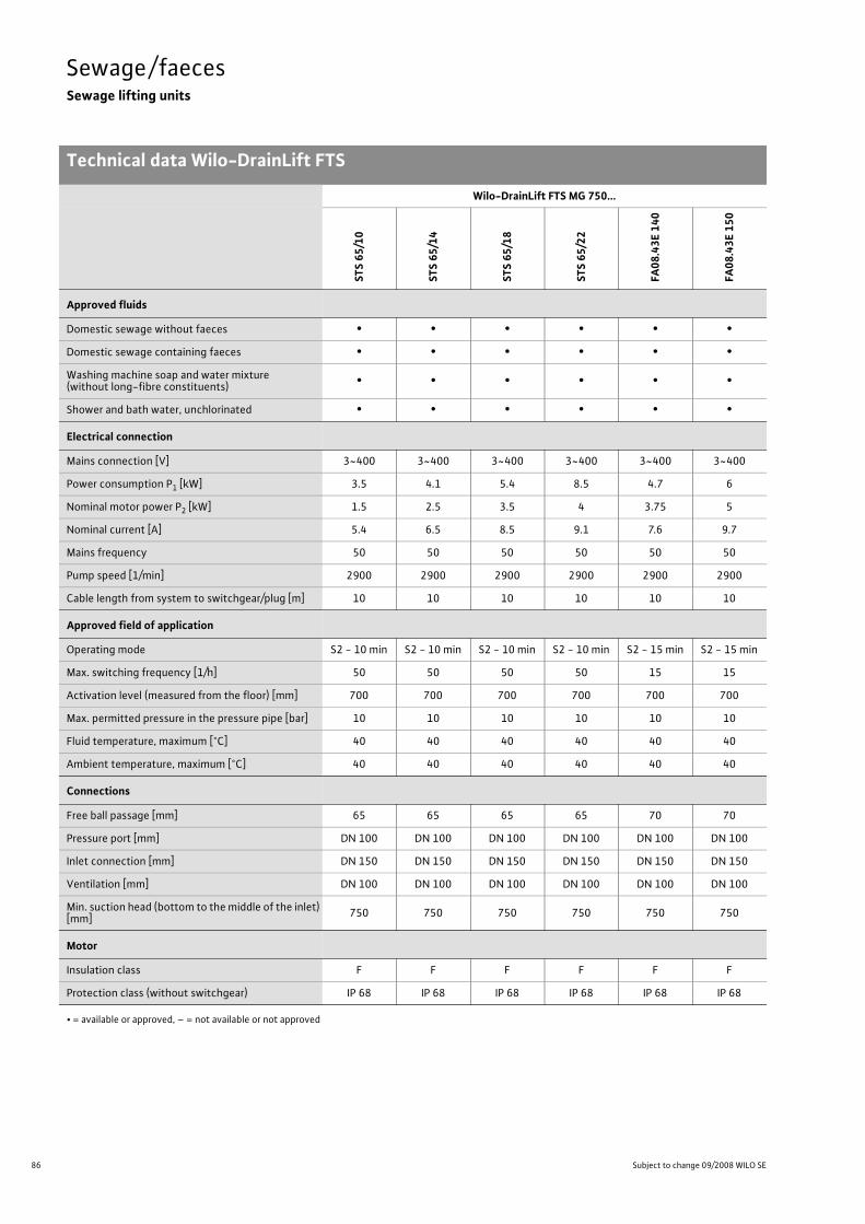
86 Subject to change 09/2008 WILO SE
Sewage/faecesSewage lifting units
Technical data Wilo-DrainLift FTS
Wilo-DrainLift FTS MG 750...
STS
65/10
STS
65/14
STS
65/18
STS
65/22
FA08
.43E
140
FA08
.43E
150
Approved fluids
Domestic sewage without faeces • • • • • •Domestic sewage containing faeces • • • • • •Washing machine soap and water mixture(without long-fibre constituents) • • • • • •
Shower and bath water, unchlorinated • • • • • •
Electrical connection
Mains connection [V] 3~400 3~400 3~400 3~400 3~400 3~400
Power consumption P1 [kW] 3.5 4.1 5.4 8.5 4.7 6
Nominal motor power P2 [kW] 1.5 2.5 3.5 4 3.75 5
Nominal current [A] 5.4 6.5 8.5 9.1 7.6 9.7
Mains frequency 50 50 50 50 50 50
Pump speed [1/min] 2900 2900 2900 2900 2900 2900
Cable length from system to switchgear/plug [m] 10 10 10 10 10 10
Approved field of application
Operating mode S2 - 10 min S2 - 10 min S2 - 10 min S2 - 10 min S2 - 15 min S2 - 15 min
Max. switching frequency [1/h] 50 50 50 50 15 15
Activation level (measured from the floor) [mm] 700 700 700 700 700 700
Max. permitted pressure in the pressure pipe [bar] 10 10 10 10 10 10
Fluid temperature, maximum [°C] 40 40 40 40 40 40
Ambient temperature, maximum [°C] 40 40 40 40 40 40
Connections
Free ball passage [mm] 65 65 65 65 70 70
Pressure port [mm] DN 100 DN 100 DN 100 DN 100 DN 100 DN 100
Inlet connection [mm] DN 150 DN 150 DN 150 DN 150 DN 150 DN 150
Ventilation [mm] DN 100 DN 100 DN 100 DN 100 DN 100 DN 100
Min. suction head (bottom to the middle of the inlet) [mm] 750 750 750 750 750 750
Motor
Insulation class F F F F F F
Protection class (without switchgear) IP 68 IP 68 IP 68 IP 68 IP 68 IP 68
• = available or approved, – = not available or not approved

87
Sewage/faecesSewage lifting units
Technical data Wilo-DrainLift FTS
Wilo Catalogue C3 - 50 Hz - Wastewater and sewage lifting units, pumps stations
Cond
ensate/w
astewater/
draina
geSe
wag
e/faeces
Pumps
station
sElectrical
accessorie
sWilo
-Drain
Dimensions/weights
Gross volume [l] 400 400 400 400 400 400
Switching volume [l] 300 300 300 300 300 300
Tank volume [l] 400 400 400 400 400 400
Weight [kg] 240 242 246 250 292 299
Wilo-DrainLift FTS MG 750...
STS
65/10
STS
65/14
STS
65/18
STS
65/22
FA08
.43E
140
FA08
.43E
150
• = available or approved, – = not available or not approved
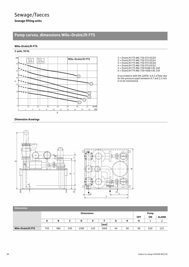
88 Subject to change 09/2008 WILO SE
Sewage/faecesSewage lifting units
Pump curves, dimensions Wilo-DrainLift FTS
Wilo-DrainLift FTS
2-pole, 50 Hz
1 = DrainLift FTS MG 750 STS 65/102 = DrainLift FTS MG 750 STS 65/143 = DrainLift FTS MG 750 STS 65/184 = DrainLift FTS MG 750 STS 65/225 = DrainLift FTS MG 750 FA08.43E 1406 = DrainLift FTS MG 750 FA08.43E 150
In accordance with EN 12056-4,6.1 a flow rate (in the pressure pipe) between 0.7 and 2.3m/s is to be maintained.
Dimension drawings
Dimensions
Dimensions PumpOFF ON ALARM
A B C D E F G K H I J[mm]
Wilo-DrainLift FTS 750 980 330 1380 110 1060 40 60 90 610 125
H
[m]
0
5
10
15
20
25
30
Q
[m³/h]
[l/s]
2010 4030 50 60 700
20 64 108 1412 16 2018
Wilo-DrainLift FTS
1
3
4
5
2
6
Q minDN 80
Q minDN 100
D
A
B
K
E
F
C
HI
J
G

89
Sewage/faecesSewage lifting units
System example Wilo-DrainLift FTS
Wilo Catalogue C3 - 50 Hz - Wastewater and sewage lifting units, pumps stations
Cond
ensate/w
astewater/
draina
geSe
wag
e/faeces
Pumps
station
sElectrical
accessorie
sWilo
-Drain
System example
1 Ventilation and exhaust, DN 100 for KG pipe
2 Pressure pipe PE 110 x 6.63 Filling level sensor4 Non-return valve DN 1005 Solids tank6 Sewage pump7 Collection reservoir8 Floor fixation M169 Inlet DN 150 for KG pipe10 Cleaning opening11 Suction connection ½", male thread
2
1
3
95
75
5
1 6
692
8
8
10
6
4
11
3
7

90 Subject to change 09/2008 WILO SE
Sewage/faecesSewage lifting units
Installation example Wilo-DrainLift FTS
Installation example
� Backflow level (usually street level)1 Ventilation and exhaust2 Pressure pipe3 Filling level sensor4 Non-return valve5 Solids tank6 Sewage pump7 Collection reservoir8 Floor fixation9 Inlet DN 15010 Cleaning opening11 Inlet slide valve (accessory)12 Gate valve (accessory)13 Wilo-Drain switchgear
(see electr. accessories)14 Drainage pump (e.g. Twister)15 Diaphragm hand pump (accessory)16 3-way cock (accessory)17 Small alarm switchgear18 Y-pipe19 Fitting support for weight relief
1713
1
119
19
18
12
3
15
8
6
16
4
5
7
14
2
10

91
Sewage/faecesSewage lifting units
Wilo Catalogue C3 - 50 Hz - Wastewater and sewage lifting units, pumps stations
Cond
ensate/w
astewater/
draina
geSe
wag
e/faeces
Pumps
station
sElectrical
accessorie
sWilo
-Drain

92 Subject to change 09/2008 WILO SE
Planning guidePumps stations
General information:
• Backflow fittings and slide valves are to be generally placed high up in the sump in the pressure pipe since deposits are avoided this way and the fittings are easily accessible for maintenance, cleaning and in-spection.
• Check valves are to be generally provided for maintenance and repair work. These are sometimes required by the standards.
• Pressure pipes are to be dimensioned according to the parameters specified in the relevant standards, e.g. flow rates and pressure stage.
• The pump sump is to be designed as small as possible around the pump.
• At the inlet of the sump, strong surge currents on the pump and components of the level sensors are to be avoided.
• During the building phase, a foundation or earthing strip is to be pro-vided for potential equalisation.
• If the outlet of the pressure pipe lies underneath the suction port of the pump, a ventilator, e.g. vacuum interrupter (accessory) is to be installed in the common pressure pipe to avoid the pump sump being sucked out up to underneath the suction port.
Double-pump pumps station
1 Foot elbow2 Non-return valve3 Gate valve4 Y-piece (Y-pipe)5 Guide pipe6 Inlet7 Pressure outlet8 Empty conduit for cables9 Ventilation pipe
9
58
6
7 4
3
2
1
6
7
4
89

93
Planning guidePumps stations
Wilo Catalogue C3 - 50 Hz - Wastewater and sewage lifting units, pumps stations
Cond
ensate/w
astewater/
draina
geSe
wag
e/faeces
Pumps
station
sElectrical
accessorie
sWilo
-Drain
Determining the volume flowThe accumulated domestic sewage volumes are calculated roughly according to the water consumption of the community in question. They depend on the number of residents “E” as well as the wastewa-ter outflow “a” in litres [l] per resident and day (l/ET, according to ex-perience approx. 120 l/ET). Under the condition that the maximum hourly outflow Qmax is one fourteenth of the average daily outflow, the following results:
When dimensioning the pressure pipe, make sure that the minimum flow rate of 0.7 m/s is maintained. To take the rainwater and ground water into account, which accumulates on the sewage side even when the drainage system is separated, the calculated value is to be increased by 50 - 130%. More information can be found in the “Sew-age technology” planning guide (on order).
Determining the size of the usable suction space of sewage pumping stationsThe usable impoundment volume of the suction space depends on the permissible switching frequency and the volume flow of the larg-est pump installed. With two identical pumps and automatically al-ternating activation, the volume can be cut in half.The permissible switching frequency “S” for each pump is not to be exceeded (depending on the selected pump type, see “Equipment/function”).For higher motor power ratings or switching frequencies, please con-sult Wilo.The volumes indicated in the diagram are minimum values required to ensure smooth pumping operation under unfavourable conditions. This is the case when the inflow for a pump is half of the volume flow. This results in a maximum number of activation operations per hour.For Wilo synthetic sumps WS 40-50, 625, 900, 1100, the usable im-poundment volume is defined as follows, depending on the selected pump type:WS 40-50: 55 - 160 lWS 625: 95 - 150 lWS 900: 110 - 150 lWS 1100: 200 - 280 l
Qmax in [l/s] =E x a
14 x 60 x 60
40
30
4
3
V[m³]
50
20
10
5
2
1
40
30
4
3
20 50 100 200 300 500 1000 2000 3000 5000 Q[Igpm]
20 50 100 200 300 500 1000 2000 3000 5000 Q[Ugpm]
1 2 3 4 5 10 20 30 40 50 100 200 300 400 500 Q[l/s]
V[m³]
50
20
10
5
2
1
5 10 20 30 40 50 100 200 300 500 1000 2000 Q[m³/h]
S=1
S=2
S=3
S=4
S=5
S=6
S=8
S=10
S=12
S=15
S=20
Volume flow

94 Subject to change 09/2008 WILO SE
Pumps stationsWastewater and sewage pumps stations
Series overview Wilo-DrainLift WS
Series: Wilo-DrainLift WS 40-50
>Synthetic pumps station> Application:• Wastewater and sewage pumping station for drainage and pressure drainage:- In the building as lifting unit in accordance with EN 12050
-Outside the building as pumps station in accordance with EN 752
Series: Wilo-DrainLift WS 625
>Synthetic pumps station> Application:• Wastewater and sewage pumping station for drainage and pressure drainage, outside the building as pumps station in accordance with EN 752.
Series: Wilo-DrainLift WS 900/1100
>Synthetic pumps station> Application:• Wastewater and sewage pumping station for drainage and pressure drainage, outside the building as pumps station in accordance with EN 752.
H[m
]
0
25
20
15
10
5
Q[m³/h]8 12 16 20 24 28 32 36 40 44 48 5240
Wilo-DrainLiftWS 40 - WS 50
MTS 40/...
TC 40
TP 65
TP 50
H[m
]
0
25
20
15
10
5
Q[m³/h]6 8 10 12 14 16420
Wilo-DrainLiftWS 625
MTS 40/...STS 40, TC 40TMW 32/11
H[m
]
0
24
32
16
10
Q[m³/h]60 80 10040200
TP80STS65TP65
Wilo-DrainLiftWS 900/1100
MTS40
TP50
TS40

95
Pumps stationsWastewater and sewage pumps stations
Series overview Wilo-DrainLift WS
Wilo Catalogue C3 - 50 Hz - Wastewater and sewage lifting units, pumps stations
Cond
ensate/w
astewater/
draina
geSe
wag
e/faeces
Pumps
station
sElectrical
accessorie
sWilo
-Drain
Series: Wilo-DrainLift WS 40-50
>Product advantages• Freely selectable inlets• Flexible use: As lifting unit inside buildings or as pumps station outside buildings.• Large tank volume (200/400 l)• Flexible installation due to optional sump length extension• Easy installation and maintenance of the pumps due to surface coupling when the Wilo-Drain TP50, TP65, MTS 40/21...27 pumps are used
• Also with macerator pumps Wilo-Drain MTS 40/21...27
>Additional information: Page• Series description . . . . . . . . . . . . . . . . 96• Pump curves . . . . . . . . . . . . . . . . . . . . 98• Dimensions . . . . . . . . . . . . . . . . . . . . . . 99• Inlet areas . . . . . . . . . . . . . . . . . . . . . . . 100• Version example . . . . . . . . . . . . . . . . . 101• Installation example . . . . . . . . . . . . . . 102• Mechanical accessories . . . . . . . . . . . 103
Series: Wilo-DrainLift WS 625
>Product advantages• Smaller sump diameter (625 mm)• Flexible use due to different installation heights• Complete due to integrated fittings and seals• Can be walked on or driven over, depending on the cover (accessories)• Also with macerator pumps Wilo-Drain MTS 40/21...27
>Additional information: Page• Series description . . . . . . . . . . . . . . . . 105• Pump curves, dimensions . . . . . . . . . 106• Dimensions . . . . . . . . . . . . . . . . . . . . . . 107• Installation example . . . . . . . . . . . . . . 108• Mechanical accessories . . . . . . . . . . . 109
Series: Wilo-DrainLift WS 900/1100
>Product advantages• Deposit-free collection space• Maximum strength due to hemispherically shaped sump floor• 2/4 inlets can be selected onsite• V4A stainless steel pipework• Also with macerator pumps Wilo-Drain MTS 40/21...39
>Additional information: Page• Series description . . . . . . . . . . . . . . . . 112• Technical data . . . . . . . . . . . . . . . . . . . 113• Pump curves; dimensions . . . . . . . . . 114• Mechanical accessories . . . . . . . . . . . 115

96 Subject to change 09/2008 WILO SE
Pumps stationsWastewater and sewage pumps stations
Series description Wilo-DrainLift WS 40 Basic
Wilo-DrainLift WS 40 BasicSynthetic pumps station
Type keyExample: Wilo-DrainLift WS 40E/TC40/8 (3~)-BV
WS Synthetic pumps station40 Pressure outlet of the systemE E = Single-pump system
D = Double-pump systemTC 40/8 Selected pump type(3~) Three-phase motorBV Backflow preventer
ApplicationThe Wilo-DrainLift WS 40 Basic is, in accordance with EN 12050-2, an automatically operating wastewater lifting unit for the backflow-proof drainage of sewage that is free of faeces from discharge points under the backflow level in buildings.The system can be installed in buildings as well as outside buildings in the same way as a plastic sump in the ground. The system is ideally suited for applications that involve seasonal wastewater (such as at camping sites, weekend homes, etc.) or in regions where the ground does not freeze to very deep levels.
Built-in pumpTC 40For severely contaminated fluids; 35mm free ball passage.
Design- For supply line in DN 100-Ventilation pipe connection in DN 70-Maximum pressure in the pressure pipe 4 bar- Synthetic pumps station made of recyclable PE-Maximum upward pressure reliability and inherent stability due to finning
- Inlets can be freely selected onsite
In the case of double-pump systems, the pressure line connection must be established onsite.
Scope of delivery-Tank (for single- or double-pump system)- Built-in pipework- Backflow preventer- Pump- Level switching- Switchgear (for three-phase pump or double-pump system)-Cover with seal (can be walked on up to 200 kg)-Hole saw � 124 mm, inlet seal DN 100 (for pipe � 110mm)-1 PVC hose section � 50mm with clamps for connecting a dia-phragm hand pump
- Fixation material for floor fixation- Installation and operating instructions
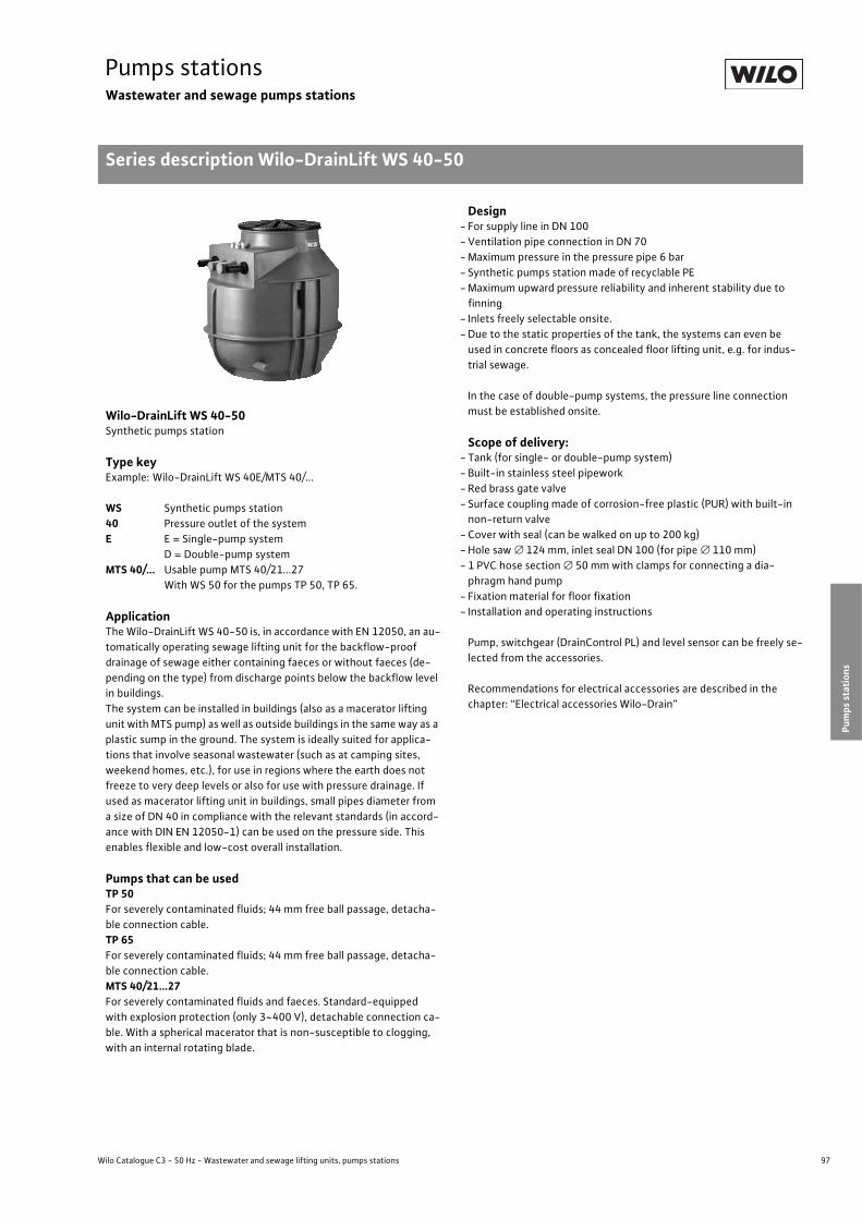
97
Pumps stationsWastewater and sewage pumps stations
Series description Wilo-DrainLift WS 40-50
Wilo Catalogue C3 - 50 Hz - Wastewater and sewage lifting units, pumps stations
Cond
ensate/w
astewater/
draina
geSe
wag
e/faeces
Pumps
station
sElectrical
accessorie
sWilo
-Drain
Wilo-DrainLift WS 40-50Synthetic pumps station
Type keyExample: Wilo-DrainLift WS 40E/MTS 40/...
WS Synthetic pumps station40 Pressure outlet of the systemE E = Single-pump system
D = Double-pump systemMTS 40/... Usable pump MTS 40/21...27
With WS 50 for the pumps TP 50, TP 65.
ApplicationThe Wilo-DrainLift WS 40-50 is, in accordance with EN 12050, an au-tomatically operating sewage lifting unit for the backflow-proof drainage of sewage either containing faeces or without faeces (de-pending on the type) from discharge points below the backflow level in buildings.The system can be installed in buildings (also as a macerator lifting unit with MTS pump) as well as outside buildings in the same way as a plastic sump in the ground. The system is ideally suited for applica-tions that involve seasonal wastewater (such as at camping sites, weekend homes, etc.), for use in regions where the earth does not freeze to very deep levels or also for use with pressure drainage. If used as macerator lifting unit in buildings, small pipes diameter from a size of DN 40 in compliance with the relevant standards (in accord-ance with DIN EN 12050-1) can be used on the pressure side. This enables flexible and low-cost overall installation.
Pumps that can be usedTP 50For severely contaminated fluids; 44 mm free ball passage, detacha-ble connection cable.TP 65For severely contaminated fluids; 44 mm free ball passage, detacha-ble connection cable.MTS 40/21...27For severely contaminated fluids and faeces. Standard-equipped with explosion protection (only 3~400 V), detachable connection ca-ble. With a spherical macerator that is non-susceptible to clogging, with an internal rotating blade.
Design- For supply line in DN 100-Ventilation pipe connection in DN 70-Maximum pressure in the pressure pipe 6 bar- Synthetic pumps station made of recyclable PE-Maximum upward pressure reliability and inherent stability due to finning
- Inlets freely selectable onsite.-Due to the static properties of the tank, the systems can even be used in concrete floors as concealed floor lifting unit, e.g. for indus-trial sewage.
In the case of double-pump systems, the pressure line connection must be established onsite.
Scope of delivery:- Tank (for single- or double-pump system)- Built-in stainless steel pipework- Red brass gate valve- Surface coupling made of corrosion-free plastic (PUR) with built-in non-return valve
- Cover with seal (can be walked on up to 200 kg)-Hole saw � 124 mm, inlet seal DN 100 (for pipe � 110mm)- 1 PVC hose section � 50mm with clamps for connecting a dia-phragm hand pump
- Fixation material for floor fixation- Installation and operating instructions
Pump, switchgear (DrainControl PL) and level sensor can be freely se-lected from the accessories.
Recommendations for electrical accessories are described in the chapter: “Electrical accessories Wilo-Drain”

98 Subject to change 09/2008 WILO SE
Pumps stationsWastewater and sewage pumps stations
Pump curves Wilo-DrainLift WS 40-50
Wilo-DrainLift WS 40-50
Duty chart of pump types that can be used, Wilo-Drain (50 Hz)
For individual pump curves, see the technical data for the selected pump.
In accordance with EN 12056-4 a flow rate (in the pressure pipe)between 0.7 and 2.3m/s is to be maintained.
H[m
]
0
25
20
15
10
5
Q[m³/h]8 12 16 20 24 28 32 36 40 44 48 5240
Wilo-DrainLiftWS 40 - WS 50
MTS 40/...
TC 40
TP 65
TP 50
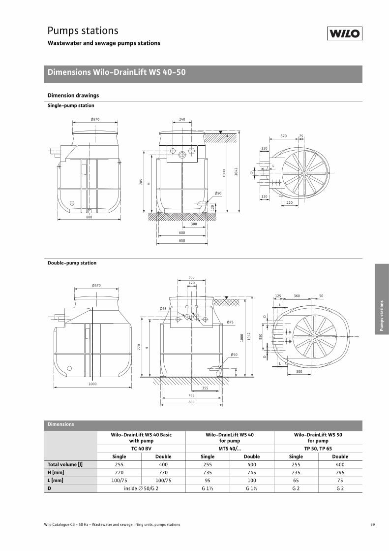
99
Pumps stationsWastewater and sewage pumps stations
Dimensions Wilo-DrainLift WS 40-50
Wilo Catalogue C3 - 50 Hz - Wastewater and sewage lifting units, pumps stations
Cond
ensate/w
astewater/
draina
geSe
wag
e/faeces
Pumps
station
sElectrical
accessorie
sWilo
-Drain
Dimension drawings
Single-pump station
Double-pump station
Dimensions
Wilo-DrainLift WS 40 Basicwith pump
Wilo-DrainLift WS 40for pump
Wilo-DrainLift WS 50for pump
TC 40 BV MTS 40/... TP 50, TP 65Single Double Single Double Single Double
Total volume [l] 255 400 255 400 255 400H [mm] 770 770 735 745 735 745L [mm] 100/75 100/75 95 100 65 75D inside � 50/G 2 G 1½ G 1½ G 2 G 2
800
Ø570 240
600
650
300
78
5
H
10
00
10
42
Ø50
12
0
D
L
120
120
370 75
220
Ø570
1000
350
120
Ø63
Ø75
355
765
800
Ø50
77
0
H
10
00
10
42
35
0D
D
125
L
L
360 50
300

100 Subject to change 09/2008 WILO SE
Pumps stationsWastewater and sewage pumps stations
Inlet areas Wilo-DrainLift WS 40-50
Freely selectable inlet areas
Wilo-DrainLift WS 40-50
min
. 4
50
ma
x.
62
0
min
. 4
50
ma
x.
62
0
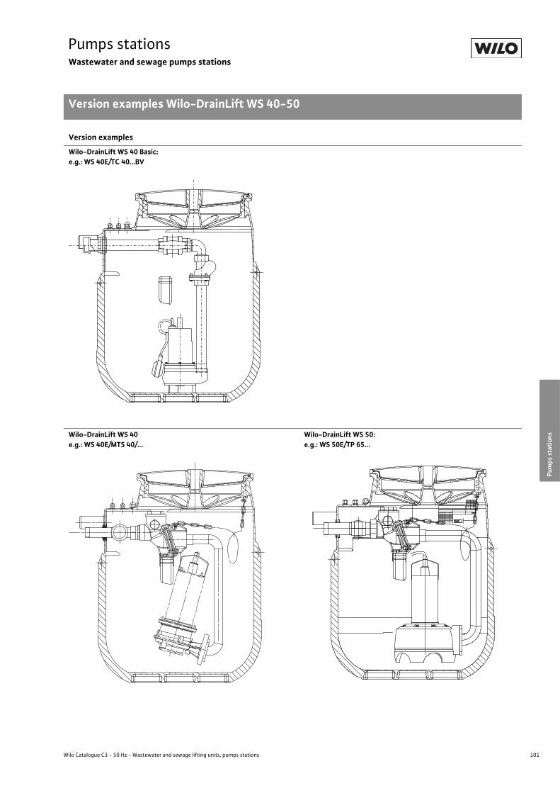
101
Pumps stationsWastewater and sewage pumps stations
Version examples Wilo-DrainLift WS 40-50
Wilo Catalogue C3 - 50 Hz - Wastewater and sewage lifting units, pumps stations
Cond
ensate/w
astewater/
draina
geSe
wag
e/faeces
Pumps
station
sElectrical
accessorie
sWilo
-Drain
Version examples
Wilo-DrainLift WS 40 Basic:e.g.: WS 40E/TC 40...BV
Wilo-DrainLift WS 40e.g.: WS 40E/MTS 40/...
Wilo-DrainLift WS 50:e.g.: WS 50E/TP 65...

102 Subject to change 09/2008 WILO SE
Pumps stationsWastewater and sewage pumps stations
Installation examples Wilo-DrainLift WS 40-50
Installation examples
Floor-mounted installation
� Backflow level (generally street level)
1 Gate valve DN 100 (accessory)2 Flange piece DN 100 (accessory)3 3-way cock (accessory)4 Diaphragm hand pump (accessory)5 Clamp bolting (accessory)6 Pressure pipe to the main collection
pipe.7 Wilo-Drain switchgear (see electr.
accessories)8 Ventilation (DN 70 connection)9 Inlet (DN 100 connection)10 Gate valve (accessory)11 Drainage pump (e.g. Twister)12 Fitting support for weight relief
Concealed floor installation
6 Pressure outlet8 Ventilation (DN 70 connection)9 Inlet (DN 100 connection)13 Sump length extension (accessory)
8
7
4 10
11
31
2
5
9
6
2
12
50
8
6
13
9

103
Pumps stationsWastewater and sewage pumps stations
Mechanical accessories Wilo-DrainLift WS 40-50
Wilo Catalogue C3 - 50 Hz - Wastewater and sewage lifting units, pumps stations
Cond
ensate/w
astewater/
draina
geSe
wag
e/faeces
Pumps
station
sElectrical
accessorie
sWilo
-Drain
Mechanical accessories
Gate valve DN 100 (item 1)for installation in the DN 100 feed line in accordance with applicable standards (incl. fixation material).
Gate valve (item 10)Gate valve 1½" or 2" for pressure outlet.
Flange piece DN 100 (item 2)for connecting the gate valve DN 100 in the feed line.
Inlet seal set DN 100 (for item 9)Seal for pipe � 110mm and hole saw (� 124 mm) for the freelyselectable inlet connection on the sump.
3-way cock (item 3)for connecting a diaphragm hand pump for draining both the system tank and an existing pump sump.
4004238

104 Subject to change 09/2008 WILO SE
Pumps stationsWastewater and sewage pumps stations
Mechanical accessories Wilo-DrainLift WS 40-50
Diaphragm hand pump R 1 ½ (item 4)for draining both the system tank and an existing pump sump.
Clamp bolting (item 5)for connecting the WS 40-50 to a PE pressure pipe:1½" (female thread) for 50mm outer �1½" (female thread) for 63mm outer �2" (female thread) for 63mm outer �2" (female thread) for 75mm outer �
Vacuum interrupter (non-return valve 1")for retrofitting in WS 40-50 when there is an underpressure in the pressure pipe onsite.
Sump length extension (item 12)Extension 300mm with seal and fastening screws. Only one extension per sump possible.
Mechanical accessories
PLASSIM

105
Pumps stationsWastewater and sewage pumps stations
Series description Wilo-DrainLift WS 625
Wilo Catalogue C3 - 50 Hz - Wastewater and sewage lifting units, pumps stations
Cond
ensate/w
astewater/
draina
geSe
wag
e/faeces
Pumps
station
sElectrical
accessorie
sWilo
-Drain
Wilo-DrainLift WS 625Synthetic pumps station
Type keyExample: Wilo-DrainLift WS 625 E/1800 MTS 40
WS Synthetic pumps station625 Inside sump diameterE Single pump sump1800 Sump heightMTS 40/... Selected MTS 40/21...27
ApplicationWilo-DrainLift WS625 is a single pump sump for pumping wastewa-ter and sewage in building services out of rooms and from areas be-low the backflow level (EN 752). It is suitable as a pumps station for pressure drainage and as a pumping station for pressurised drainage. The WS 625 is used in the ground outside the building. A time-saving, easy-to-install, low-cost solution for all planners and build-ing contractors.
Pump types that can be used
TMW 32/Slightly contaminated fluids (free of faeces), 10mm free ball passage.
STS 40 and TC 40For severely contaminated fluids (free of faeces);STS 40: free ball passage 40mmTC 40: free ball passage 35mm
MTS 40/21 ... 27For severely contaminated fluids and faeces. Standard-equipped with explosion protection (only 3~ 400 V), detachable connection cable. With a spherically shaped macerator that is non-susceptible to clogging, with internal rotating blade.
DesignThe Wilo-DrainLift WS 625 is available in 4 lengths, 1200, 1500, 1800 and 2100mm.The sump can be equipped both with a standard cover that can be walked on, and also with covers of class A (can be walked on) or class B/D (can be driven over).
-Maximum pressure in the pressure pipe 6 bar, in conjunction with MTS 40, other pumps 4 bar
- Synthetic pumps station made of recyclable PE-Maximum upward pressure reliability and inherent stability by means of finning up to a ground water level above the entire sump height (upper edge of site)
Scope of delivery:- PE sump with internal pipework including coupling sleeve slider 1¼" and non-return valve (with TMW 32/11 integrated in the pump),
- Seal mounted for inlet DN 100- Seal mounted for ventilation/electrical connection (DN 100).- Seal mounted for pressure pipe (DN 40/� 50).- Pump (for MTS 40 incl. floor support base) with matching discharge pipe,
- Installation and operating instructions.
Switchgear and level sensor can be selected freely as accessories.
Recommendations for electrical accessories are described in the chapter: “Electrical accessories Wilo-Drain”.

106 Subject to change 09/2008 WILO SE
Pumps stationsWastewater and sewage pumps stations
Pump curves, dimensions Wilo-DrainLift WS 625
Wilo-DrainLift WS 625
Duty chart of pump types that can be used, Wilo-Drain (50 Hz)
For individual pump curves, see the technical data for the selected pump.
In accordance with EN 12056-4 a flow rate (in the pressure pipe)between 0.7 and 2.3m/s is to be maintained.
Dimension drawing
Wilo-DrainLift WS 625 E/1200
H[m
]
0
25
20
15
10
5
Q[m³/h]6 8 10 12 14 16420
Wilo-DrainLiftWS 625
MTS 40/...STS 40, TC 40TMW 32/11
Ø625
60
0
Ø5
0
40
0 30
0
Ø715
60
DN
10
0 :
Ø1
10
50
0
B
A
30
°
TMW 32/11 STS 40TC 40

107
Pumps stationsWastewater and sewage pumps stations
Dimensions Wilo-DrainLift WS 625
Wilo Catalogue C3 - 50 Hz - Wastewater and sewage lifting units, pumps stations
Cond
ensate/w
astewater/
draina
geSe
wag
e/faeces
Pumps
station
sElectrical
accessorie
sWilo
-Drain
Dimension drawing
Wilo-DrainLift WS 625 E/1500-2100...
Dimensions
Wilo-DrainLift … DimensionsA [mm] B [mm]
WS 625 E/1200 1260 600WS 625 E/1500 1560 900WS 625 E/1800 1860 1200WS 625 E/2100 2160 1500
Ø625
84
0
Ø5
0
40
0 30
0
Ø715
60
DN
10
0 :
Ø1
10
A
Ø1
10
60
0
B
TMW 32/11 STS 40TC 40

108 Subject to change 09/2008 WILO SE
Pumps stationsWastewater and sewage pumps stations
Installation example Wilo-DrainLift WS 625
Installation example
Concealed floor installation: WS 625
1 Clamp bolting (accessory)2 Pressure pipe (accessory, incl. non-return valve, item 3)3 Non-return valve R 1 ¼4 Gate valve 1¼" (scope of delivery)5 Inlet DN 1006 Ventilation DN 1007 Sump cover (accessory)
6
3
2
5
7
4
1
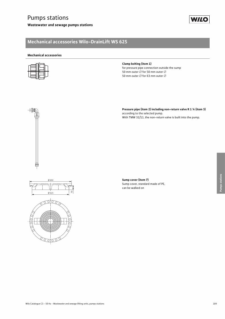
109
Pumps stationsWastewater and sewage pumps stations
Mechanical accessories Wilo-DrainLift WS 625
Wilo Catalogue C3 - 50 Hz - Wastewater and sewage lifting units, pumps stations
Cond
ensate/w
astewater/
draina
geSe
wag
e/faeces
Pumps
station
sElectrical
accessorie
sWilo
-Drain
Mechanical accessories
Clamp bolting (item 1)for pressure pipe connection outside the sump50mm outer � for 50mm outer �50mm outer � for 63mm outer �
Pressure pipe (item 2) including non-return valve R 1 ¼ (item 3)according to the selected pump.With TMW 32/11, the non-return valve is built into the pump.
Sump cover (item 7)Sump cover, standard made of PE,can be walked on
Ø 692
Ø 615 70
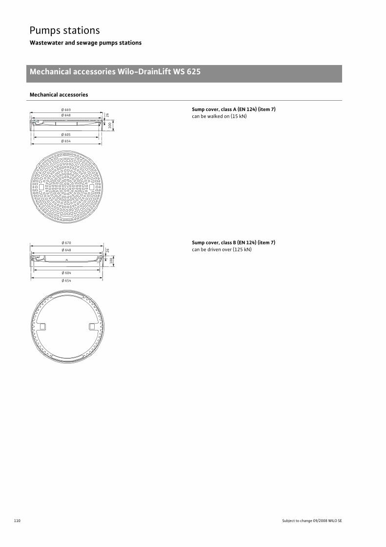
110 Subject to change 09/2008 WILO SE
Pumps stationsWastewater and sewage pumps stations
Mechanical accessories Wilo-DrainLift WS 625
Sump cover, class A (EN 124) (item 7)can be walked on (15 kN)
Sump cover, class B (EN 124) (item 7)can be driven over (125 kN)
Mechanical accessories
26
10
0
Ø 648
Ø 669
Ø 605
Ø 654
Ø 670
Ø 648
Ø 604
Ø 654
26
10
0

111
Pumps stationsWastewater and sewage pumps stations
Mechanical accessories Wilo-DrainLift WS 625
Wilo Catalogue C3 - 50 Hz - Wastewater and sewage lifting units, pumps stations
Cond
ensate/w
astewater/
draina
geSe
wag
e/faeces
Pumps
station
sElectrical
accessorie
sWilo
-Drain
Sump cover, class D (EN 124) (item 7)can be driven over (400 kN)
Mechanical accessories
Ø 707
Ø 684
Ø 680
R331Ø 610
Ø 665
50
60
16
0
810
1107

112 Subject to change 09/2008 WILO SE
Pumps stationsWastewater and sewage pumps stations
Series description Wilo-DrainLift WS 900/1100
Wilo-DrainLift WS 900/1100Synthetic pumps station
Type keyExample: Wilo-DrainLift WS 900 E/MTS 40
WS Synthetic pumps station 900 Sump diameter
900 = 900 mm1100 = 1100 mm
E E = single pumpD = double pump
MTS 40 Selected pump type
ApplicationWilo-DrainLift WS 900/1100 is a single/double pump sump for pumping wastewater and sewage in building services out of rooms and from areas below the backflow level (EN 752). It is suitable as a pumps station that is read for connection for pres-sure drainage and as a pumping station for pressurised drainage.The WS 900/1100 is used in the ground outside the building. A time-saving, easy-to-install, low-cost solution for all planners and build-ing contractors.
Pump types that can be used
TS 40Slightly contaminated fluids (free of faeces), 10mm free ball passage, detachable connection cable.
TP 50For severely contaminated fluids (free of faeces); 44 mm free ball passage, detachable connection cable.
TP 65For severely contaminated fluids (free of faeces); 44 mm free ball passage, detachable connection cable.
STS 65For severely contaminated fluids (containing faeces or free of fae-ces), 65mm free ball passage, detachable connection cable, vortex hydraulics non-susceptible to clogging. For connection to a DN 65 pressure pipe in compliance with DIN EN 12050-2 and EN 12050-1.For connection to a DN 80 pressure pipe in compliance with DIN EN 12050-1 and DIN EN 12050-2.
TP 80For severely contaminated fluids and faeces; 80mm free ball pas-sage. Standard-equipped with explosion protection, detachable con-nection cable (only when used as a single-pump station).
MTS 40For severely contaminated fluids and faeces. Standard-equipped with explosion protection (only 3~400 V), detachable connection ca-ble. With patented macerator:- Internal rotating blade- Spherically formed macerator- Absolutely reliable
Design-Maximum traffic load 5 kN/m2 (in acc. with DIN EN 124, Group 1)-Maximum pressure in the pressure pipe 6 bar- Synthetic pumps station made of recyclable PE-High upward pressure reliability due to 2/4 (WS 900 = 2 x, WS 1100 =
4 x) standard-equipped with lateral fins (no concrete rings required)-2/4 inlets can be selected onsite-Maximum strength due to moulded hemispherical shape of the sump floor, up to an immersion depth of 1.20m into the ground water.
-Wilo-surface-coupling-2 DN 100 connection pieces for ventilation and connection cable- Deposit-free collecting space due to moulded hemispherical shape of the pump sump
- Easy access to the level sensor, due to installation with hinged sup-porting bar
Scope of delivery- Pipework made of stainless steel, from the pump pressure port to ap-prox. 10 cm outside the sump
- Surface coupling system including seals-Non-return valve, gate valve completely mounted- Flush connection G 1½- Stainless steel chain including fastening hook- Supporting bar for level monitoring (level sensor, float switch) includ-ing installation accessoriesDouble pumping stations are each supplied with twice the quantity of surface couplings and fittings.
-Connection material for two DN 150 KG inlet pipes- Installation and operating instructions

113
Pumps stationsWastewater and sewage pumps stations
Technical data Wilo-DrainLift WS 900/1100
Wilo Catalogue C3 - 50 Hz - Wastewater and sewage lifting units, pumps stations
Cond
ensate/w
astewater/
draina
geSe
wag
e/faeces
Pumps
station
sElectrical
accessorie
sWilo
-Drain
Wilo-DrainLift WS 900 with pump Wilo-DrainLift WS 1100 with pump
TS 40 TP 50 TP 65STS 65 MTS 40 TP 50 TP 65/STS 65 TP 80 MTS 40
Single Double Single Single Single Double Single Double Single Single Single Double
Total volume [l] 890 880 890 890 880 1230 1230 1230 1220 1220 1215 1220
Impoundment volume [l](bottom to upper edge of inlet) 300 290 300 300 290 550 540 550 540 520 535 510
Switching volume [l] max. 150 110 140 130 150 270 200 250 200 200 280 250
Inlet [DN] 150 150 150 150 150 150 150 150 150 150 150 150
Pressure outlet 1 ½" 1 ½" 2" 2 ½" 1 ½" 2" 2" 2 ½" 2 ½" DN 80 1 ½" 1 ½"
Ventilation/cable [DN] 100 100 100 100 100 100 100 100 100 100 100 100
Non-return valve GG25 1 ½" 1 ½" 2" 2 ½" 1 ½" 2" 2" 2 ½" 2 ½" DN 80 1 ½" 1 ½"
Gate valve made of material
1½"red
brass
1 ½"red
brass
2"red
brass
2 ½"red
brass
1 ½"red
brass
2"red
brass
2"red
brass
2 ½"red
brass
2 ½"red
brass
DN 80GG25
1 ½"red
brass
1 ½"red
brass
Weight [kg] 70 95 73 75 72 95 113 97 115 125 94 110

114 Subject to change 09/2008 WILO SE
Pumps stationsWastewater and sewage pumps stations
Pump curves, dimensions Wilo-DrainLift WS 900, WS 1100
Wilo-DrainLift WS 900/1100
Duty chart of pump types that can be used, Wilo-Drain (50 Hz)
For individual pump curves, see the technical data for the selected pump.
In accordance with EN 12056-4 a flow rate (in the pressure pipe)between 0.7 and 2.3m/s is to be maintained.
Dimension drawings
Wilo-DrainLift WS 900 - Dimensions for sump length reduction,single-pump station
Wilo-DrainLift WS 1100 - Dimensions for pump length reduction,double-pump station
Dimensions
Wilo-DrainLift WS 900 with pump Wilo-DrainLift WS 1100 with pump
TS 40 TP 50 TP 65STS 65 MTS 40 TP 50 TP 65/STS 65 TP 80 MTS 40
Single Double Single Single Single Double Single Double Single Single Single DoubleHeight of pump “stop” dimension A [mm]
200 354 220 285 200 230 310 260 360 330 220 260
H[m
]
0
24
32
16
10
Q[m³/h]60 80 10040200
TP80STS65TP65
Wilo-DrainLiftWS 900/1100
MTS40
TP50
TS40
A
Ø 840
Ø 740
G 1½
405100
OFF
83
0
Ø856
56
0
18
00
74
0
11
70
A
43
0
31
5
19
5
A
12
60
45
°
2 x DN150
2 x DN100
22
,5°
45
°4
x90
°=3
60
°
4 x DN150
15
00
527
100
OFF
1500
2 x DN100
62
5
18
00
76
5
10
956
75
A
37
5
25
0
12
5
Ø1084
G 1½“
A
A
Ø 840
Ø 740

115
Pumps stationsWastewater and sewage pumps stations
Mechanical accessories Wilo-DrainLift WS 900, WS 1100
Wilo Catalogue C3 - 50 Hz - Wastewater and sewage lifting units, pumps stations
Cond
ensate/w
astewater/
draina
geSe
wag
e/faeces
Pumps
station
sElectrical
accessorie
sWilo
-Drain
Mechanical accessories
Sump length extension made of PE(� 730 x 800mm), incl. installation accessories, seal and supporting bar extension for level sensor (special lengths on request).A maximum of 1 extension per sump is possible.Other extensions are not permitted.
Pump cover made of PE“Standard” � 830mm including non-slip profile on the upper side and two internal locks, can be walked on.
Pump cover made of PE“Overflow-proof” � 960 x 100mm including non-slip profile on the upper side and six exterior locks made of stainless steel, can be walked on.
Clamp bolting made of PEfor pressure pipe connection outside the sump
- 1½" (Rp (female thread)) for 50mm outer �- 1½" (Rp (female thread)) for 63mm outer �- 2" (Rp (female thread)) for 63mm outer �
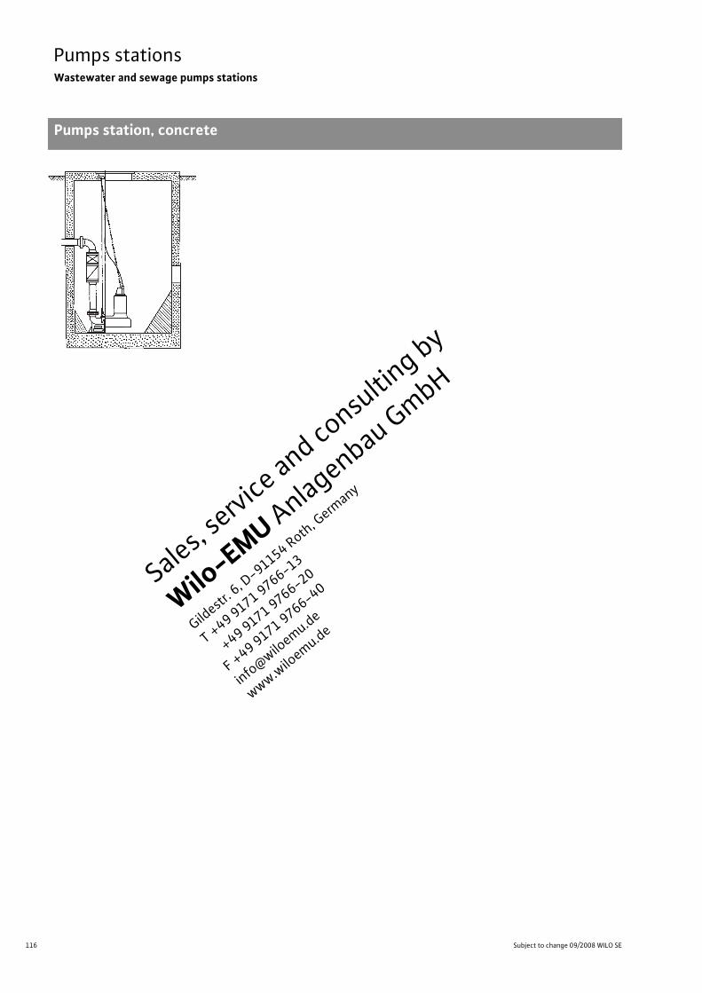
116 Subject to change 09/2008 WILO SE
Pumps stationsWastewater and sewage pumps stations
Pumps station, concrete
Sales,
serv
ice and consulti
ng by
Wilo
-EMU A
nlagenbau G
mbH
Gildest
r. 6, D
-91154 Roth
, Germ
any
T +49 9
171 9766-13
+49 9171 9
766-20
F +49 9
171 9766-40
info
@w
iloem
u.de
ww
w.w
iloem
u.de

Wilo-DrainLift WS 625.
Ready-to-install synthetic sump.
For wastewater and sewage disposal.
Can be walked on and driven over.
Can be operated easily from above.
The Wilo-DrainLift WS 625 wastewater and sewage sump is a pumps station with a small
diameter: optimal for pressurised drainage. Installation is quick and easy: in addition, this
anti-buoyant shaft is easily installed outside of the building in the ground.
In combination with the submersible motor pumps Wilo-Drain TMW 32/11,
TC 40 and MTS 40/ ... , it is perfectly suited for the disposal of wastewater
and sewage which accumulates underneath the backflow level.
Powerful? We call this Pumpen Intelligenz.
www.wilo.com

118 Subject to change 09/2008 WILO SE
Electrical accessories Wilo-DrainWastewater and sewage lifting units, pumps stations
Recommended accessories
Wilo
-EC-
Drain
1x
4,01
)
Wilo
-EC-
Drain
2x
4,02
)
Wilo
-Drain
-Co
ntrol P
L11)
Wilo
-Drain
-Co
ntrol
PL1
WS1
)
Wilo
-Drain
-Co
ntrol P
L22)
Wilo
-Drain
-Co
ntrol
PL2
WS2
)
Wilo
-Drain
-Co
ntrol 1
1)
Wilo
-Drain
-Co
ntrol 2
2)
Lifting units
Wilo-DrainLift Con – – – – – – – –
Wilo-DrainLift TMP – – – – – – – –
Wilo-DrainLiftBox – o – – – – – –
Wilo-DrainLift KH 32 – – – – – – – –
Wilo-DrainLift XS-F – – – – – – – –
Wilo-DrainLift S – – – – – – – –
Wilo-DrainLift M – – – – – – – –
Wilo-DrainLift L – – – – – – – –
Wilo-DrainLift XL – – – – – – – –
Wilo-DrainLift XXL – – – – – – – –
Wilo-DrainLift FTS – – – – – – – –
Pumps stations
Wilo-DrainLift WS 40 Basic – – – – – – – –
Wilo-DrainLift WS 40-50 – – � • � • – –
Wilo-DrainLift WS 625 – – � • � • � �
Wilo-DrainLift WS 900/1100 – – � • � • � �
• = recommended, � = optional, – = not required1) Switchgear for 1 pump, 2) Switchgear for 2 pumps

119
Electrical accessories Wilo-DrainWastewater and sewage lifting units, pumps stations
Recommended accessories
Wilo Catalogue C3 - 50 Hz - Wastewater and sewage lifting units, pumps stations
Cond
ensate/w
astewater/
draina
geSe
wag
e/faeces
Pumps
station
sElectrical
accessorie
sWilo
-Drain
Wilo
KAS
Wilo
-Drain
-Alarm
2
Wilo
-Alarm
-Co
ntrol 1
Wilo
-Alarm
-Co
ntrol 2
Motor
protection
plug
CEE
Leve
l sen
sor
Floa
t switch
MS1
Floa
t switch
WA
Lifting units
Wilo-DrainLift Con – – – – – – – –
Wilo-DrainLift TMP – – � • – – – –
Wilo-DrainLiftBox � � � • – – – �
Wilo-DrainLift KH 32 – – � • – – – –
Wilo-DrainLift XS-F – – – – – – – –
Wilo-DrainLift S � � � � – – – –
Wilo-DrainLift M – – – – – – – –
Wilo-DrainLift L – – – – – – – –
Wilo-DrainLift XL – – – – – – – –
Wilo-DrainLift XXL – – – – – – – –
Wilo-DrainLift FTS � � � � – – – –
Pumps stations
Wilo-DrainLift WS 40 Basic � � � � – – – �
Wilo-DrainLift WS 40-50 � � � � – • � �
Wilo-DrainLift WS 625 � � � � – • � �
Wilo-DrainLift WS 900/1100 � � � � – • � �
• = recommended, � = optional, – = not required

120 Subject to change 09/2008 WILO SE
Electrical accessories Wilo-DrainWastewater and sewage lifting units, pumps stations
Recommended accessories
Dyn
amic
pressure
system
Bubb
ling-
throug
h system
Ex-rated
cut
-off
relay
Brea
kdow
n ba
rrier
Switc
h cabine
t
Flash lig
ht
Sign
al horn
Lifting units
Wilo-DrainLift Con – – – – – � �
Wilo-DrainLift TMP – – – – – � �
Wilo-DrainLiftBox – – – – – � �
Wilo-DrainLift KH 32 – – – – – � �
Wilo-DrainLift XS-F – – – – – � �
Wilo-DrainLift S – – – – – � �
Wilo-DrainLift M – – – – – � �
Wilo-DrainLift L – – – – – � �
Wilo-DrainLift XL – – – – – � �
Wilo-DrainLift XXL – – – – – � �
Wilo-DrainLift FTS – – – � – � �
Pumps stations
Wilo-DrainLift WS 40 Basic – – – – � � �
Wilo-DrainLift WS 40-50 – – � � � � �
Wilo-DrainLift WS 625 � � � � � � �
Wilo-DrainLift WS 900/1100 � � � � � � �
• = recommended, � = optional, – = not required

Wilo factory customer service.
52 customer service technicians.Overwhelming availability.
1 telephone number.Everywhere in Germany.
The Wilo factory customer service technicians are partners who are there for you withtheir practical support in all of Germany 365 days a year. Your personal contact partneron site offers you all conceivable support. This local service works so well thanks to ourunparalleled organisational structure. Everything comes together in our factory-ownedWilo Service Centre. Based on this, every service call is coordinated perfectly via yourpersonal control centre, and the Wilo customer service technician will be on site to giveoptimum support with a lot of useful information. Exemplary? We call this Pumpen Intelligenz.
www.wilo.com

122 Subject to change 09/2008 WILO SE
Electrical accessories Wilo-DrainWastewater and sewage lifting units, pumps stations
Equipment/function
Wilo
-EC-
Drain
1x4,0
Wilo
-EC-
Drain
2x4,0
Wilo
-DrainCo
ntrol
PL 1/P
L 1
WS
Wilo
-DrainCo
ntrol
PL 2/P
L 2
WS
Wilo
-DrainCo
ntrol 1
Wilo
-DrainCo
ntrol 2
Wilo
KAS
Application
Switchgear for controlling pumps • • • • • • –
Alarm switchgear – – – – – – •Number of pumps to be controlled 1 2 1 2 1 2 –
Electrical connection
Direct activation [A] Max. 12 Max. 2 x 12 Max. 12 Max. 2 x 12 Max. 10 Max. 2 x 10 –
Star/delta switching – – – – > 10 A > 10 A –
Design
Microprocessor-controlled – • • • • • –
Electronic • – – – – – •
Housing material
Plastic • • • • • • •Metal – – – – – – –
Equipment
Test run – • • • – – –
Pump starts counter/pulse counter – – • • – – –
LC display – – • • • • –
LED/control lamp • • • • • • –
Main switch • ••
(only withPL 1 WS)
•(only withPL 2 WS)
• • –
Ampere display – – • • • 2) • 2) –
Voltmeter – – – – – – –
Adjustable follow-up time – – • • • • –
Operating hours counter – – • • • • –
Level measurement Float switch • 3) • 3) • 3) • 3) • 3) • 3) –
Pneumatic pressure sensor – – • • – – –
Level sensor (4-20 mA) – – • 4) • 4) • 4) • 4) –
Electrodes – – – – – – •Alarm Mains-dependent • • • • • • –
Built-in (buzzer) • • • • – – •Pump cycling – • – • – • –
1) For other motor power ratings on request2) Only for direct activation devices (up to 4 kW)3) In potentially explosive areas only with ex-rated cut-off relay
4) In potentially explosive areas only with breakdown barrier
• = available, – = not available
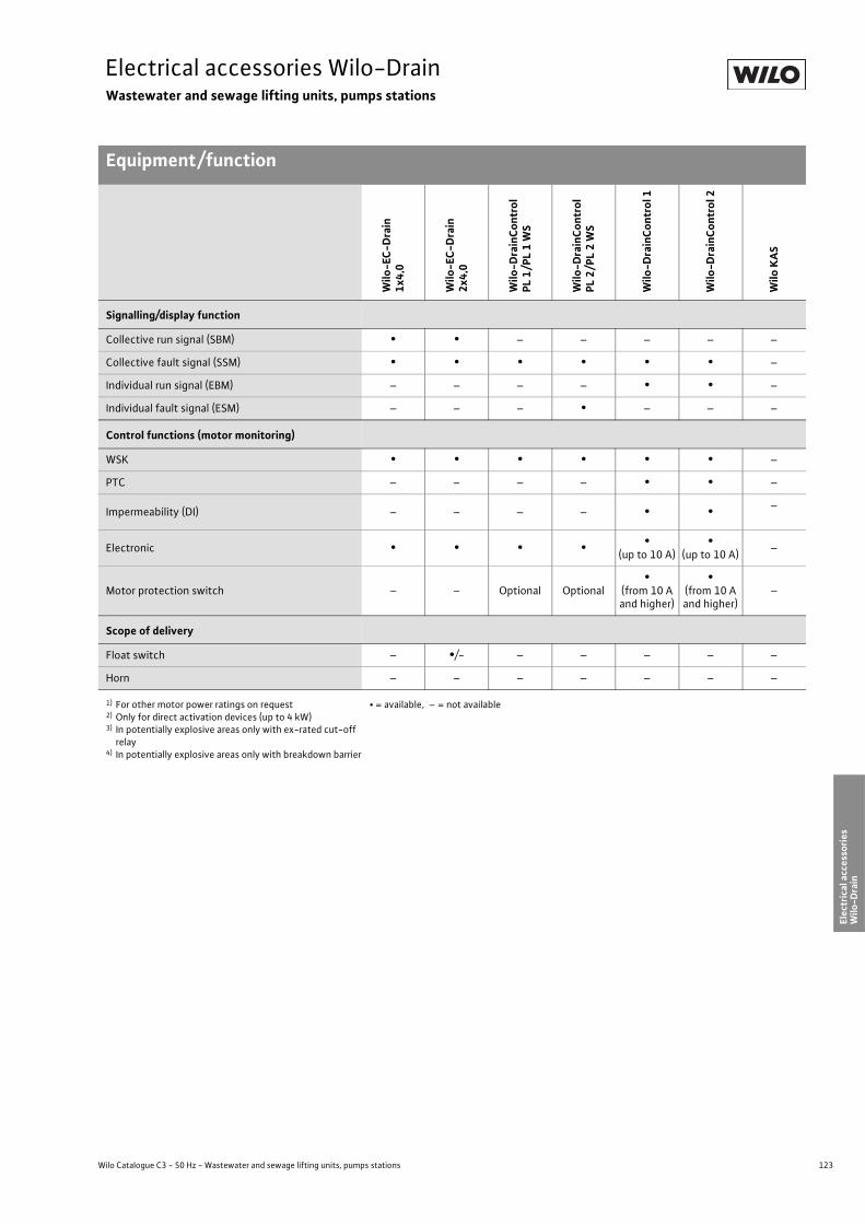
123
Electrical accessories Wilo-DrainWastewater and sewage lifting units, pumps stations
Equipment/function
Wilo Catalogue C3 - 50 Hz - Wastewater and sewage lifting units, pumps stations
Cond
ensate/w
astewater/
draina
geSe
wag
e/faeces
Pumps
station
sElectrical
accessorie
sWilo
-Drain
Signalling/display function
Collective run signal (SBM) • • – – – – –
Collective fault signal (SSM) • • • • • • –
Individual run signal (EBM) – – – – • • –
Individual fault signal (ESM) – – – • – – –
Control functions (motor monitoring)
WSK • • • • • • –
PTC – – – – • • –
Impermeability (DI) – – – – • • –
Electronic • • • • •(up to 10 A)
•(up to 10 A) –
Motor protection switch – – Optional Optional•
(from 10 A and higher)
•(from 10 A and higher)
–
Scope of delivery
Float switch – •/- – – – – –
Horn – – – – – – –
Wilo
-EC-
Drain
1x4,0
Wilo
-EC-
Drain
2x4,0
Wilo
-DrainCo
ntrol
PL 1/P
L 1
WS
Wilo
-DrainCo
ntrol
PL 2/P
L 2
WS
Wilo
-DrainCo
ntrol 1
Wilo
-DrainCo
ntrol 2
Wilo
KAS
1) For other motor power ratings on request2) Only for direct activation devices (up to 4 kW)3) In potentially explosive areas only with ex-rated cut-off relay
4) In potentially explosive areas only with breakdown barrier
• = available, – = not available

124 Subject to change 09/2008 WILO SE
Electrical accessories Wilo-DrainWastewater and sewage lifting units, pumps stations
Equipment/function
• = available, – = not available
Wilo
Drain
-Alarm
2
Wilo
-Alarm
Control 1
Wilo
-Alarm
Control 2
Motor
protection
plug
CEE
Ex-rated
cut
-off
relay
Brea
kdow
n ba
rrier
Flash lig
ht
Sign
al horn
Wilo
SK
545
Application
Switchgear for controlling pumps – – – • – – – – –
Alarm switchgear • • • – – – – – –
Number of pumps to be controlled – – – 1 – – – – 2
Electrical connection
Direct activation [A]
– – – • – – – – –External power section
Star/delta switching
– – – – – – – – –External power section
Design
Electronic • • • – • • • – •Electromechanical – – – • – – – • –
Housing material
Plastic • • • • • • • • •
Equipment
LED/control lamp • – – • • – – – •Level measurement Float switch • • • • • – – – –
Pneumatic pressure sensor – – – – – – – – –
Level sensor (4-20 mA) – – – – – • – – –
Electrodes – – – – – – – – –
Alarm Mains-independent • • • – – – – – –
Mains-dependent • • • – – – – – –
Built-in (buzzer) • • • – – – – – –
Socket 1~230 V – – • – – – – – –
Signalling/display function
Individual fault signal (ESM) • • – – – – – – –
Control functions (motor monitoring)
WSK – – – • – – – – •Impermeability (DI) – – – – – – – – •Motor protection switch – – – • – – – – –

125
Electrical accessories Wilo-DrainWastewater and sewage lifting units, pumps stations
Product descriptions
Wilo Catalogue C3 - 50 Hz - Wastewater and sewage lifting units, pumps stations
Cond
ensate/w
astewater/
draina
geSe
wag
e/faeces
Pumps
station
sElectrical
accessorie
sWilo
-Drain
Switchgear Wilo-EC-Drain 1x4,0
Electronically controlled switchgear for the automatic, transmitter-dependent control of 1 submersible wastewater/sewage pump of the Wilo-Drain series.
• Full motor protection by integrated motor current monitoring and thermal winding contact evaluation.
• Lockable main switch• Transmitter connection for float switch, types WA 65, WA 95• Button for manual operation of the pump• High water alarm• Forced activation with high water• Potential-free fault signal (changeover contact) and potential-free run signal (changeover contact)
• Integrated mains-dependent alarm buzzer• Operation, high water and malfunction display via LEDs on the front panel
Technical data:Operating voltage: 1~230 V, 3~400 V, 3~230 VConnected load P2: 4.0 kWMaximum current: 12 AFrequency: 50/60 HzProtection class: IP 65 (within buildings/switch cabinets)Dimensions (W x H x D): 215 x 220 x 125mm
Attention: Switchgears are not protected against explosions and may only be used outside of potentially explosive areas. Ex-rated cut-off relays are to be provided for controlling pumps in potentially explosive areas.
Switchgear Wilo-EC-Drain 2x4,0
Microprocessor-controlled switchgear for the automatic, transmitter-dependent control of 2 submersible wastewater/sewage pumps of the Wilo-Drain series.
• Motor protection via integrated thermal winding contact evaluation.• Lockable main switch• Transmitter connection for float switch, types WA 65, WA 95 and MS 1• 2 buttons for manual operation of the pumps• Adjustable pump kick function for a pump start of 3 sec. after a downtime of 7 days.• High water alarm• Forced activation with high water• Potential-free fault signal (changeover contact) and potential-free run signal (changeover contact)
• Integrated mains-dependent alarm buzzer• Operation, high water and malfunction display via LEDs on the front panel• Optionally for controlling explosion-protected pumps.
Technical data:Operating voltage: 1~230 V, 3~400 V, 3~230 VConnected load P2: 2 x 4.0 kWMaximum current: 2 x 12 AFrequency: 50/60 HzProtection class: IP 54Dimensions (W x H x D): 300 x 230 x 113mm
Attention: Switchgears are not protected against explosions and may only be used outside of potentially explosive areas. Ex-rated cut-off relays are to be provided for controlling pumps in potentially explosive areas.

126 Subject to change 09/2008 WILO SE
Electrical accessories Wilo-DrainWastewater and sewage lifting units, pumps stations
Product descriptions
Switchgear Wilo-DrainControl PL 1
Switchgear for controlling the level of 1 submersible pump. Level measurement can be carried out using either the bubbling-through system or the dynamic pressure system, with float switches or electronic level sensors.
• LC display• LED for alarm, operation/follow-up time, manual/automatic mode• Input terminals for connecting float switches (WA 65, WA 95 or MS1) or for connecting a level sensor (factory setting: level sensor 0-1 mWS (4-20 mA)). Level sensors from 0-1 mWS to 0-5mWS can be connected as an option. They are set using the switchgear menu.
• Potential-free contacts for collective fault signal and high water alarm• Forced activation of the pump• Pump deactivation with follow-up time• Integrated buzzer• Operating hours counter, pump starts
Technical data:Operating voltage: 1~230 V, 3~400 VFrequency: 50/60 HzProtection class: IP 65 (within buildings/switch cabinets)Dimensions (W x H x D): 180 x 255 x 180mm
Attention: Switchgears are not protected against explosions and may only be used outside of potentially explosive areas. A level sensor in the potentially explosive area (with breakdown barrier!) or a float switch (in the potentially explosive area with ex-rated cut-off relay) is to be provided for controlling the pump.
Switchgear Wilo-DrainControl PL 1 WS
Switchgear for controlling the level of 1 submersible pump. Level measurement can be carried out using either the bubbling-through system or the dynamic pressure system, with float switches or electronic level sensors.
• LC display• LED for alarm, operation/follow-up time, manual/automatic mode• Input terminals for connecting float switches (WA 65, WA 95 or MS1) or for connecting a level sensor (factory setting: level sensor 0-1 mWS (4-20 mA)). Level sensors from 0-1 mWS to 0-5mWS can be connected as an option. They are set using the switchgear menu.
• Potential-free contacts for collective fault signal and high water alarm• Forced activation of the pump• Pump deactivation with follow-up time• Integrated buzzer• Operating hours counter, pump starts• Lockable main switch• 3~mains, no neutral conductor necessary
Technical data:Operating voltage: 1~230 V, 3~400 VFrequency: 50/60 HzProtection class: IP 65 (within buildings/switch cabinets)Dimensions (W x H x D): 180 x 255 x 180mm
Attention: Switchgears are not protected against explosions and may only be used outside of potentially explosive areas. A level sensor in the potentially explosive area (with breakdown barrier!) or a float switch (in the potentially explosive area with ex-rated cut-off relay) is to be provided for controlling the pump.

127
Electrical accessories Wilo-DrainWastewater and sewage lifting units, pumps stations
Product descriptions
Wilo Catalogue C3 - 50 Hz - Wastewater and sewage lifting units, pumps stations
Cond
ensate/w
astewater/
draina
geSe
wag
e/faeces
Pumps
station
sElectrical
accessorie
sWilo
-Drain
Switchgear Wilo-DrainControl PL 2
Switchgear for controlling the levels of 2 submersible pumps. Level measurement can be car-ried out using either the bubbling-through system or the dynamic pressure system, with float switches or electronic level sensors.
• LC display, multi-language switching• LED for alarm, operation/follow-up time, manual/automatic mode• Input terminals for connecting float switches (WA 65, WA 95 or MS1) or for connecting a level sensor (factory setting: level sensor 0-2.5 mWS (4-20 mA)). Level sensors from 0-1 mWS to 0-5 mWS can be connected as an option. They are set using the switchgear menu.
• Potential-free contact for collective fault signal and high water alarm, malfunction pump 1, malfunction pump 2
• Forced activation of the pump• Pump deactivation with follow-up time• Automatic fault-actuated switchover• Integrated buzzer• Operating hours counter, pump starts
Technical data:Operating voltage: 1~230 V, 3~400 VFrequency: 50/60 HzProtection class: IP 65 (within buildings/switch cabinets)Dimensions (W x H x D): 320 x 300 x 120mm
Attention: Switchgears are not protected against explosions and may only be used outside of potentially explosive areas. A level sensor in the potentially explosive area (with breakdown barrier!) or a float switch (in the potentially explosive area with ex-rated cut-off relay) is to be provided for controlling the pump.
Switchgear Wilo-DrainControl PL 2 WS
Switchgear for controlling the levels of 2 submersible pumps. Level measurement can be car-ried out using either the bubbling-through system or the dynamic pressure system, with float switches or electronic level sensors.
• LC display, multi-language switching• LED for alarm, operation/follow-up time, manual/automatic mode• Input terminals for connecting float switches (WA 65, WA 95 or MS1) or for connecting a level sensor (factory setting: level sensor 0-1 mWS (4-20 mA)). Level sensors from 0-1 mWS to 0-5mWS can be connected as an option. They are set using the switchgear menu.
• Potential-free contact for collective fault signal and high water alarm, malfunction pump 1, malfunction pump 2
• Forced activation of the pump• Pump deactivation with follow-up time• Automatic fault-actuated switchover• Integrated buzzer• Operating hours counter, pump starts• Lockable main switch• 3~mains, no neutral conductor necessary
Technical data:Operating voltage: 1~230 V, 3~400 VFrequency: 50/60 HzProtection class: IP 65 (within buildings/switch cabinets)Dimensions (W x H x D): 320 x 300 x 120mm
Attention: Switchgears are not protected against explosions and may only be used outside of potentially explosive areas. A level sensor in the potentially explosive area (with breakdown barrier!) or a float switch (in the potentially explosive area with ex-rated cut-off relay) is to be provided for controlling the pump.
1 2
1 2

128 Subject to change 09/2008 WILO SE
Electrical accessories Wilo-DrainWastewater and sewage lifting units, pumps stations
Product descriptions
Switchgear Wilo-DrainControl 1/2
Microprocessor-controlled switchgear for the fully automatic control of 1 or 2 submersible wastewater/sewage pumps of the Wilo-Drain series.
• Manual-0-Automatic switch via keypad• Two-line LCD-display with 2 x 16 x characters, multilingual, switchable, menu-driven operat-ing option via keypad
• Input terminals for connecting a level sensor- Standard: 0-2.5mWs (4-20mA)-Optional: 0-1 mWs (4-20mA) or 0-5mWs (4-20mA)
• Input terminals for connecting float switches WA 65, WA 95 or MS1• Automatic phase failure and rotating field control• Operating hours counter• Pump cycling (Control 2) after each pumping operation• Potential-free contacts for: -Collective fault signal- Signal horn (NO contact)-Operation of pump 1 (NO contact)-Operation of pump 2 (NO contact) only Control 2
• Main switch• Integrated electronic motor current monitoring• Maximum ambient temperature 40 °C• Housing: Plastic for wall-mounted installation• Starting mode: Direct or star-delta
Technical data:Operating voltage: 1~230 V, 3~400 V, 3~230 VFrequency: 50 HzProtection class: IP 54Dimensions (W x H x D): depend on the model
Attention: Switchgears are not protected against explosions and may only be used outside of potentially explosive areas. A level sensor in the potentially explosive area (with breakdown barrier!) or a float switch (in the potentially explosive area with ex-rated cut-off relay) is to be provided for controlling the pump.
Small alarm switchgear Wilo KAS
Small alarm switchgear with signalling tone 70 dBA, signal transmitter (electrode) with 3m cable, self-charging power supply unit (battery backup approx. 5 hrs) in ISO plug housing (shock-proof), protection class IP 30, 230 V~/9 V=; 1.5 VA.
Wilo Drain-Alarm 2
Alarm switchgear for wall-mounted installation with optical and acoustic alarm signals (buzzer) 85 dBA self-charging power supply unit, potential-free contact, ISO housing, protection class IP 54, 1~230 V. A type WA float switch is required as transmitter.

129
Electrical accessories Wilo-DrainWastewater and sewage lifting units, pumps stations
Product descriptions
Wilo Catalogue C3 - 50 Hz - Wastewater and sewage lifting units, pumps stations
Cond
ensate/w
astewater/
draina
geSe
wag
e/faeces
Pumps
station
sElectrical
accessorie
sWilo
-Drain
Alarm switchgears Wilo-AlarmControl 1/2
Wilo-AlarmControl 1:Mains-independent alarm system with shock-proof plug. Rechargeable battery, acoustic alarm signal (buzzer), mini float switch with 3 m cable mounted on the device. With potential-free contact and ISO housing IP 20.
Wilo-AlarmControl 2:Mains-independent alarm system with shock-proof plug and integrated socket for connecting an appliance, e.g. a washing machine. Rechargeable battery, acoustic alarm signal (buzzer), mini float switch with 3 m cable mounted on the device. With ISO housing IP 20.
Technical data:-Operating voltage: 1~230 V, 50 Hz-Control voltage: 12 VDC (non-stabilised)-Alarm contact for AlarmControl 1: potential-free NO contact,contact load max. 1 A (230 VAC)
- Socket contact: Contact load max. 16 A (250 VAC)- Protection class: IP 20-Housing: ABS-Cable length, mini-float switch: 3m (2 x 0.75mm2)-Max. ambient temperature: + 60 °C-Dimensions (W x H x D): 68 x 112 x 53mm
Attention: Switchgears are not protected against explosions and may only be used outside of potentially explosive areas.
Motor switchgear/motor protection plug CEE
Motor protection plug (only up to a nominal motor power of P2 < 4 kW) with phase inverter and rotation direction indicator, thermal motor protection of the motor. Power ranges:
• 1.2 – 1.8 A• 1.8 – 2.6 A• 2.6 – 3.7 A• 3.7 – 5.5 A• 5.5 – 8 A• 8 – 11.5 A
Optional with TP 80, TP 100: evaluation of thermal motor protection and leakage detection possible.
Level sensor
For level measurement.• Protection class IP 68• Measurement range 0 - 1 mWS; 0 - 2.5mWS• Cable lengths 10. 30 or 50m• Output signal 4 - 20mA• ATEX-certified

130 Subject to change 09/2008 WILO SE
Electrical accessories Wilo-DrainWastewater and sewage lifting units, pumps stations
Product descriptions
Float switch MS1
Cable length 10m, for sewage containing faeces, for connection to a Wilo-DrainControl 1 or 2.
Float switch WA
Cable length 5 m, 10 m, 20 m, 30 m, switching: up ON/down OFF.• WA 65 for fluids up to 60 °C• WA 95 for fluids up to 90 °C
Ex-rated cut-off relay
For the installation of float switches in potentially explosive areas.Suitable for connecting 2 to 5 float switches. Installed in an ISO housing, protection class IP 54, with transparent cover, for wall-mounted installation.Dimensions (W x H x D): 182 x 180 x 165mm
• 2-circuit (connection of 2 float switches possible)• 3-circuit (connection of 3 float switches possible)• 4-circuit (connection of 4 float switches possible)• 5-circuit (connection of 5 float switches possible)
Breakdown barrier
For the installation of a level sensor in potentially explosive areas.Suitable for connecting one level sensor.Protection class IP 40, housing for installation in non-explosive areas.Dimensions (W x H x D): 75 x 150 x 106 mm1 m cable premounted.
1 2
N L 3 4 5 6 7 8

131
Electrical accessories Wilo-DrainWastewater and sewage lifting units, pumps stations
Product descriptions
Wilo Catalogue C3 - 50 Hz - Wastewater and sewage lifting units, pumps stations
Cond
ensate/w
astewater/
draina
geSe
wag
e/faeces
Pumps
station
sElectrical
accessorie
sWilo
-Drain
Switch cabinet, outdoor installation for Wilo-DrainControl
Empty housing for outdoor installation, made of fibreglass-reinforced polyester, with lock, provided with ventilation and exhaust. For pedestal installation. Additional options such as ammeter, voltmeter, heating, etc. are available on request and can be immediately installed in the switch cabinet in conjunction with a Wilo-DrainControl if desired (additional charge).Dimensions (W x H x D): 590 x 875 x 320mm
Flash light
For installation on switch cabinets, outdoor installation, 230 VAC
Signal horn
For connection to Wilo-DrainControl, 230 VAC, 92 dBA
Dynamic pressure system
The pressure sensor (bell) detects changes in the fluid level in the sump. The changes of the pressure value in the bell are transmitted via a leak-proof hose to the Wilo-DrainControl switchgear and evaluated by measuring elements in the switchbox.Scope of delivery: Immersion bell with 10 m hose

132 Subject to change 09/2008 WILO SE
Electrical accessories Wilo-DrainWastewater and sewage lifting units, pumps stations
Product descriptions
Bubbling-through system
Dynamic pressure system with compressed air permanently introduced by small compressor. The immersion bell (dynamic pressure system) is to be ordered separately.Scope of delivery: Small compressor, 3 m hose, with T-piece and non-return valve
Tripping unit Wilo-SK 545
Tripping unit for monitoring a maximum of 2 Wilo submersible pumps TP 80 or 100• Installation in existing switchgears or as a module for switchgears of conventional design,installation on a 35mm top-hat rail
• Monitoring of the rotating field• Leakage detection• Thermal monitoring (WSK)• Operating voltage 3~400 V max. 6 A fuse protection• Potential-free output contacts, max. load 250 V, 1 A• Dimensions (W x H x D): 100 x 72 x 113mm

3 Änderungen vorbehalten. WILO AG 09/2007
Heating, air-conditioning, coolingCirculation pumpsGlandless pumps and accessories, package heat exchanger assembly
Heating, air-conditioning, coolingGlanded pumpsPumps with in-line design and accessories
Heating, air-conditioning, cooling, water supplyMonobloc and norm pumps, axial split case pumpsPumps and accessories
Water supply Domestic water supply, rainwater utilisationPumps, systems and accessories
Water supply Borehole pumps, 3" to 24"Pumps and systems for building services, domestic, municipal and industrial water supply
Water supply High-pressure multistage centrifugal pumpsPumps and accessories
Water supply Pressure boosting systemsSingle-pump and multi-pump systems in dry well installations
Water supply Sprinkler pumps with VdS approvalBorehole pumps and accessories
Drainage and sewageDrainage pumpsSubmersible pumps, self-priming pumps and accessories
Drainage and sewageSewage pumps, DN 32 to DN 600Submersible pumps and accessories for building services, municipal and industrial applications
Drainage and sewageWastewater and sewage lifting units, pumps stationsPump systems and accessories
Drainage and sewageSubmersible mixersMixers, re-circulation pumps, jet cleaners, grit collector pumps and accessories for municipal application in water treatment systems
Catalogue A1
Catalogue A2
Catalogue A3
Catalogue B1
Catalogue B2
Catalogue B3
Catalogue B4
Catalogue B5
Catalogue C1
Catalogue C2
Catalogue C3
Catalogue C4
UMETechnologie
UMETechnologie
UMETechnologie
UMETechnologie
Wat
ersu
pply
Dra
inag
ean
dse
wag
eHe
atin
g,ai
r-co
nditi
onin
g,co
olin
g
Wilo Catalogue Edition 2009
UMETechnologie
id
ll
df
WILO SENortkirchenstraße 10044263 DortmundGermanyT +49 231 4102-0F +49 231 [email protected]
AlgeriaBad Ezzouar, Dar El BeidaT +213 21 [email protected]
Armenia375001 YerevanT +374 10 [email protected]
Bosnia and Herzegovina71000 Sarajevo T +387 33 [email protected]
Georgia0179 TbilisiT +995 32 [email protected]
Macedonia1000 SkopjeT +389 2 [email protected]
Mexico07300 MexicoT +52 55 [email protected]
Moldova2012 ChisinauT +373 2 [email protected]
Rep. MongoliaUlaanbaatarT +976 11 [email protected]
Tajikistan734025 DushanbeT +992 37 [email protected]
Turkmenistan744000 AshgabadT +993 12 [email protected]
Uzbekistan100015 TashkentT +998 71 [email protected]
March 2009
Wilo – International (Subsidiaries)
Wilo – International (Representation offices)
ArgentinaWILO SALMSONArgentina S.A.C1295ABI CiudadAutónoma de Buenos AiresT+ 54 11 4361 [email protected]
AustriaWILO PumpenÖsterreich GmbH1230 WienT +43 507 [email protected]
AzerbaijanWILO Caspian LLC1065 BakuT +994 12 [email protected]
BelarusWILO Bel OOO220035 MinskT +375 17 [email protected]
BelgiumWILO SA/NV1083 GanshorenT +32 2 [email protected]
BulgariaWILO Bulgaria Ltd.1125 SofiaT +359 2 [email protected]
CanadaWILO Canada Inc.Calgary, Alberta T2A 5L4T +1 403 [email protected]
ChinaWILO China Ltd.101300 BeijingT +86 10 [email protected]
CroatiaWILO Hrvatska d.o.o. 10090 ZagrebT +38 51 [email protected]
Czech RepublicWILO Praha s.r.o.25101 CestliceT +420 234 [email protected]
DenmarkWILO Danmark A/S2690 KarlslundeT +45 70 [email protected]
EstoniaWILO Eesti OÜ12618 TallinnT +372 [email protected]
FinlandWILO Finland OY02330 EspooT +358 [email protected]
FranceWILO S.A.S.78390 Bois d'ArcyT +33 1 [email protected]
Great BritainWILO (U.K.) Ltd.DE14 2WJ Burton-Upon-TrentT +44 1283 [email protected]
GreeceWILO Hellas AG14569 Anixi (Attika)T +302 10 [email protected]
HungaryWILO Magyarország Kft2045 Törökbálint(Budapest)T +36 23 [email protected]
IrelandWILO Engineering Ltd.LimerickT +353 61 [email protected]
ItalyWILO Italia s.r.l.20068 PeschieraBorromeo (Milano)T +39 [email protected]
KazakhstanWILO Central Asia050002 AlmatyT +7 727 [email protected]
KoreaWILO Pumps Ltd. 621-807 GimhaeGyeongnamT +82 55 [email protected]
LatviaWILO Baltic SIA1019 RigaT +371 67 [email protected]
LebanonWILO SALMSONLebanon12022030 El MetnT +961 4 [email protected]
LithuaniaWILO Lietuva UAB03202 VilniusT +370 5 [email protected]
The NetherlandsWILO Nederland b.v.1551 NA WestzaanT +31 88 9456 [email protected]
NorwayWILO Norge AS0975 OsloT +47 22 [email protected]
PolandWILO Polska Sp. z.o.o.05-090 RaszynT +48 22 [email protected]
PortugalBombas Wilo-SalmsonPortugal Lda.4050-040 PortoT +351 22 [email protected]
RomaniaWILO Romania s.r.l.077040 Com. ChiajnaJud. IlfovT +40 21 [email protected]
RussiaWILO Rus ooo123592 MoscowT +7 495 [email protected]
Saudi ArabiaWILO ME - RiyadhRiyadh 11465T +966 1 [email protected]
Serbia and MontenegroWILO Beograd d.o.o.11000 BeogradT +381 11 [email protected]
SlovakiaWILO Slovakia s.r.o.82008 Bratislava 28T +421 2 [email protected]
SloveniaWILO Adriatic d.o.o.1000 LjubljanaT +386 1 [email protected]
South AfricaSalmson South Africa1610 EdenvaleT +27 11 [email protected]
SpainWILO Ibérica S.A.28806 Alcalá de Henares(Madrid)T +34 91 [email protected]
SwedenWILO Sverige AB35246 VäxjöT +46 470 [email protected]
SwitzerlandEMB Pumpen AG4310 RheinfeldenT +41 61 [email protected]
TaiwanWILO-EMU Taiwan Co. Ltd.110 TaipehT +886 227 [email protected]
TurkeyWILO Pompa Sistemleri San. ve Tic. A.S.34530 IstanbulT +90 216 [email protected]
UkrainaWILO Ukraina t.o.w.01033 KiewT +38 044 [email protected]
VietnamPompes Salmson VietnamHo Chi Minh-Ville VietnamT +84 8 [email protected]
United Arab EmiratesWILO ME - DubaiDubaiT +971 4 [email protected]
USAWILO-EMU USA LLCThomasville, Georgia 31792T +1 229 [email protected]
USAWILO USA LLC Melrose Park, Illinois 60160T +1 708 [email protected]
Subject to change without prior notice. In appliance of our General Terms of Delivery and Service (see www.wilo.com)
2101004/2T/0809/MP