Embed Size (px)
Citation preview
Reputed Manufacturers and Exporters of
Electrical Power System Protection Relays
and Digital Meters
www.prokdvs.comAn ISO 9001 : 2008 Certified Company
Product CatalogueProduct Catalogue

Prok Devices Private Limited a ISO 9001-2008 Certified Company established in the year 1991,
set up by four highly motivated & experienced professionals in the field of electrical and electronic
engineering. With over eight years of experience in Manufacturing, Quality Control & Inspection /
Testing & Calibration / Design & Development / Sales & Marketing, the company backed with
technical abilities of electrical engineers.Prok Devices ear marked itself as a blue chip company in
Indian & global business scenario within a decade of its establishment.
Prok Devices is reputed for its well trained technical team with an excellent 24x7 service back-up.
The strengths of the technical team relies on its vast & varied field experience gained by number of
electrical & electronic engineers working in Production &Quality Control.
Prok Devices as a brand has functioned with the registered trade mark as a
reputed manufacturer of solid state and micro controller based protection relays and digital meters
used in power system applications. The R&D wing with its in house Design & Development team is
designing & converting most of the existing product line from solid state version to state-of-the art
micro controller based versions.
The reputed brand products are exported to many International destinations
and the company has participated in a number of National & International Exhibitions
Conferences & Seminars having won various awards, grants and certifications.
All our products are approved with reputed and leading Technical Consultants, Electricity Boards,
Public Sectors, OEM’s.. Etc,
Prok Dv’s Products are widely used in Major projects like Mining, Cement, Steel, Oil Refineries,
Software Industries, Sub-Stations, Power Plants, Industries, Commercial & High Rise Buildings,
Residential & Educational Institutions.
The company is in lieu with like minded global partners & JV’s to implement the trend with ongoing
technology in the field of power system protection.
Prok Devices Pvt Ltd which swears by Quality as its maiden name has proven its track record by
obtaining International quality certification & programs. Most of the products are type tested as per
National / International Standards at Authorised Lab’s in INDIA like C.P.R.I , E.T.D.C., L.R.D.E.,
SAMEER ..etc.,
Prok D”
,
UKASQUALITY
MANAGEMENT
008D BNABCB
Excluding Design QM 003
ISO 9001
BUREAU VERITASBUREAU VERITASCertificationCertification
Company Profile
http: www.prokdvs.com2
http: www.prokdvs.com
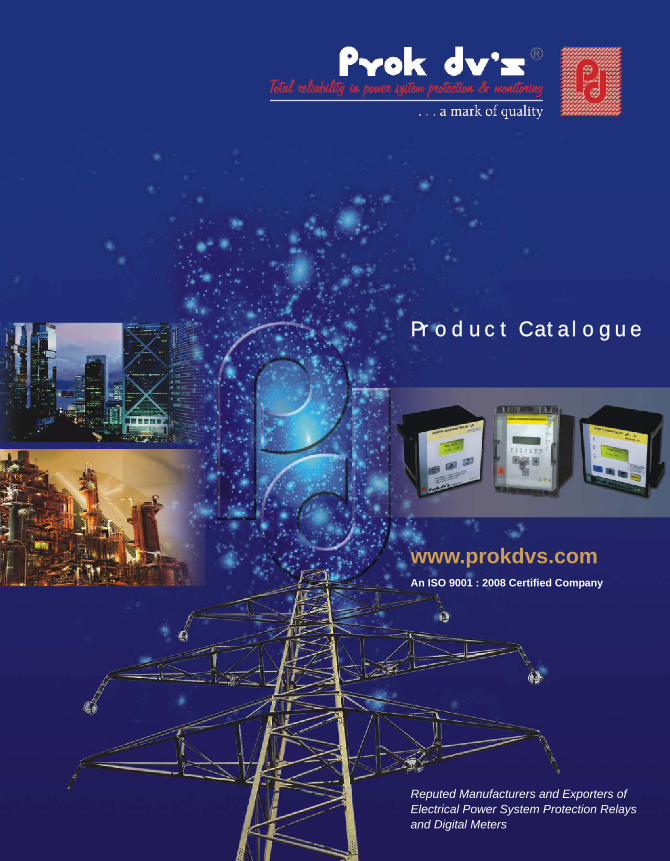
PRODUCT RANGE
DESIGN / PRODUCTS Page STATE - OF - THE - ART No.
A. Microprocessor Based 4 & Solid State
B. Microprocessor Based 6[ DMT, IDMT & Instantaneous ]
[ DMT, IDMT & Instantaneous ]
Solid State 6 [DMT & Instantaneous ]
[ DMT & Instantaneous ]
C. Microprocessor Based 7
D. Microprocessor Based 8[ DMT, IDMT & Instantaneous ]
E. Microprocessor Based 9
F. Microprocessor Based 10
G. Microprocessor Based - LVM Series 12
H. Microprocessor Based 13
I. Microprocessor Based 14
J. Microprocessor Based 15
K. Microprocessor Based - VD Series 16 & Solid State
L. Solid State 18
M. Solid State 19
N. Solid State 20
O. Solid State Counter Type 22
P. Microprocessor Based LCD Type 23
P. Microprocessor Based 25
Q. Microprocessor Based 26
R. Microprocessor Based 27
S. Microprocessor Based 28 [ ACCL ]
T. Solid State 30[ Switch mode power supplies ]
U. 31
n
n
n
n
n
n
n
n
n
n
n
n
n
n
n
n
n
n
n
n
n
n
n
n
n
EARTH LEAKAGE RELAY with CORE BALANCE CURRENT TRANSFORMER
EARTH FAULT RELAY
EARTH FAULT RELAY with CORE BALANCE CURRENT TRANSFORMER
EARTH FAULT RELAY
EARTH FAULT RELAY with CORE BALANCE CURRENT TRANSFORMER
RESTRICTED EARTH FAULT RELAY
OVER CURRENT RELAY
NUMERICAL OVER & UNDER VOLTAGE RELAY
with NEGATIVE PHASE SEQUENCE PROTECTION
NUMERICAL OVER CURRENT & EARTH FAULT RELAY
AC VOLTAGE RELAY
REVERSE POWER RELAY
FREQUENCY RELAY
INTELLIGENT POWER FACTOR CORRECTION RELAY
VOLTAGE RELAY
PHASE FAILURE RELAY
TAP POSITION INDICATOR
DIGITAL METERS
THREE PHASE ENERGY METER
THREE PHASE ENERGY METER
THREE PHASE ENERGY METER DUAL
DUAL ENERGY METER WITH POWER MONITOR
VAF METER
AUTO SOURCE CHANGE OVER CUM CURRENT LIMITER
BATTERY CHARGERS
DIMENSIONAL DRAWINGS
3
E-mail: [email protected]
FEATURESC
for
APPLICATIONS
nnnnnnnn
n
n
nn
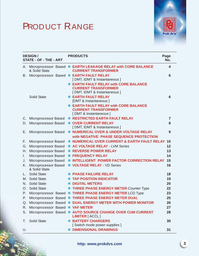
onsistent reliability with accuracyFixed or variable sensitivityDetection of CBCT open(in µP based model only)Continuous monitoring and display of leakage current(in µP based model only)LED/LCD display for visual indication of faultHigh barrier connector at rear end for easy termination and safety standardTest & Reset facility testing healthiness of the relayTamper proof polycarbonate cover in the front
Earth leakage protection for feeders/motors/generators/transformer/mobile operating equipmentsProtection of hazardous sensitive environments like oil refineries/chemical platforms/pulp industries and general electrical distribution.Protection for mining and control engineering.Software and telecom sector
A) Solid state ELRs -EL / DEL Series. ( D stands for-Din mounting)B) Microprocessor ELR MPEL / DMPEL Series ( D stands for-Din mounting)
CLASSIFICATION BASED ON DESIGN:
E-mail: [email protected]
INTRODUCTION: Earth Leakage Currents give rise to generation of heat and results in progressive failure of insulation, which leads to earth faults, sparking flashovers deterioration of earthing and finally results in catastrophic fires which can destroy costly equipments, gadgets and precious lives. It is therefore essential to detect earth leakage currents well below they cross the threshold limits and isolate the circuit in the event of leakages.
Prok dv's make Earth Leakage Relays (ELR) with Core Balance Current Transformer (CBCT) are used to detect leakage currents in electrical power systems. ELR transmits a signal to activate the trip coil of the MCCB/ACB/OCB/CONTACTOR in the event of earth leakage, resulting in automatic isolation of the load.ELR have been widely used and accepted because of field adaptability and are economic.
PRINCIPLE OF OPERATION: ELR employs core balance current transformer(CBCT) to sense the leakage current The (CBCT) is mounted externally and load current carrying cable are passed through the( CBCT). Ideally in a leakage free system the incoming and outgoing currents are equal and opposite in direction, which means that the vector sum of the three phase currents is zero and can be expressed as
Ir + Iy +Ib =0 for 3 phase 3 wire system
Ir + Iy +Ib +In=0 for 3phase 4 wire system.
For the above condition the CBCT produces zero resultant magnetic flux keeping the system healthy.
In case of earth leakage either due to insulation degradation / chemical corrosion etc. the vector sum of currents is not zero and CBCT generates voltage which is fed to the ELR.This signal is compared with the set value of leakage current and trip command is initiated if the leakage current is more than the set values of current and time.It is worthwhile to emphasize that the unequal /unbalanced loading on phases does not effect the vector sum and as such there is no difficulty in the use of ELR on electrical distribution system with unbalanced loading.
Earth leakage relay for IT,BT, UPS application, mining, cement, petroleum & oil refineries, steel , paper& pulping industries :Prok dvs recommends the use of µP based Earth Leakage Relays with CBCT for the above applications for greater Reliability and user friendly.
4
Earth Leakage RelayEarth Leakage RelayIEEE Device Code - 64
http: www.prokdvs.com
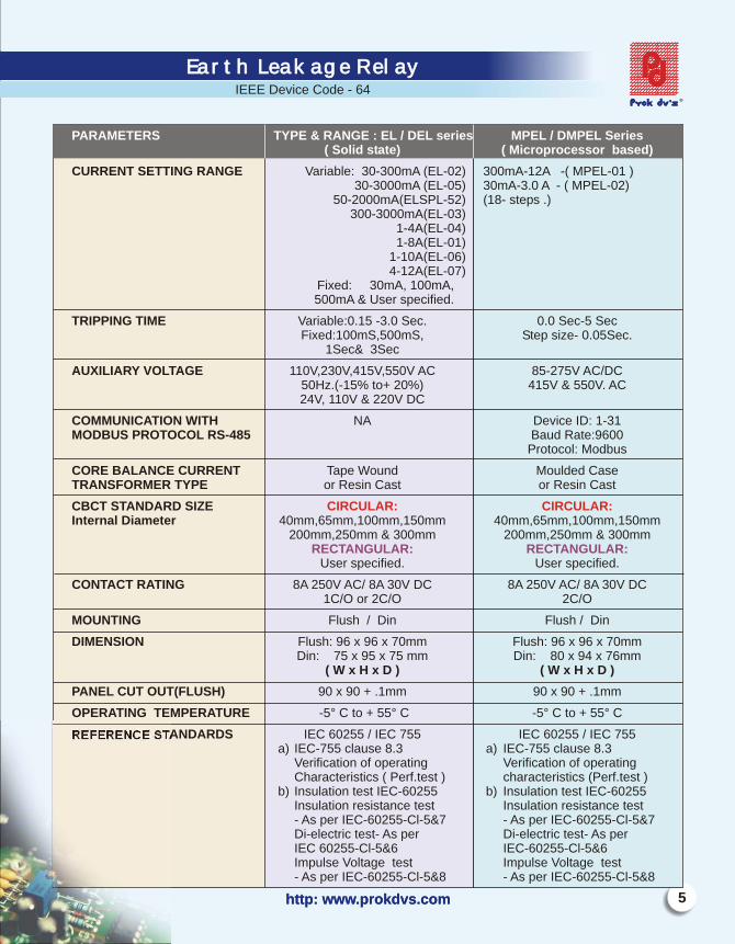
CURRENT SETTING RANGE Variable: 30-300mA (EL-02) 300mA-12A -( MPEL-01 ) 30-3000mA (EL-05) 30mA-3.0 A - ( MPEL-02)
50-2000mA(ELSPL-52) (18- steps .)300-3000mA(EL-03)
1-4A(EL-04)1-8A(EL-01)
1-10A(EL-06)4-12A(EL-07)
Fixed: 30mA, 100mA,500mA & User specified.
TRIPPING TIME Variable:0.15 -3.0 Sec. 0.0 Sec-5 Sec Fixed:100mS,500mS, Step size- 0.05Sec. 1Sec& 3Sec
AUXILIARY VOLTAGE 110V,230V,415V,550V AC 85-275V AC/DC50Hz.(-15% to+ 20%) 415V & 550V. AC24V, 110V & 220V DC
COMMUNICATION WITH NA Device ID: 1-31MODBUS PROTOCOL RS-485 Baud Rate:9600
Protocol: Modbus
CORE BALANCE CURRENT Tape Wound Moulded Case TRANSFORMER TYPE or Resin Cast or Resin Cast
CBCT STANDARD SIZE Internal Diameter 40mm,65mm,100mm,150mm 40mm,65mm,100mm,150mm
200mm,250mm & 300mm 200mm,250mm & 300mm
User specified. User specified.
CONTACT RATING 8A 250V AC/ 8A 30V DC 8A 250V AC/ 8A 30V DC 1C/O or 2C/O 2C/O
MOUNTING Flush / Din Flush / Din
DIMENSION Flush: 96 x 96 x 70mm Flush: 96 x 96 x 70mmDin: 75 x 95 x 75 mm Din: 80 x 94 x 76mm
( W x H x D ) ( W x H x D )
PANEL CUT OUT(FLUSH) 90 x 90 + .1mm 90 x 90 + .1mm
OPERATING TEMPERATURE -5° C to + 55° C -5° C to + 55° C
REFERENCE STANDARDS IEC 60255 / IEC 755 IEC 60255 / IEC 755a) IEC-755 clause 8.3 a) IEC-755 clause 8.3
Verification of operating Verification of operatingCharacteristics ( Perf.test ) characteristics (Perf.test )
b) Insulation test IEC-60255 b) Insulation test IEC-60255Insulation resistance test Insulation resistance test- As per IEC-60255-Cl-5&7 - As per IEC-60255-Cl-5&7Di-electric test- As per Di-electric test- As per IEC 60255-Cl-5&6 IEC-60255-Cl-5&6Impulse Voltage test Impulse Voltage test- As per IEC-60255-Cl-5&8 - As per IEC-60255-Cl-5&8
PARAMETERS TYPE & RANGE : EL / DEL series MPEL / DMPEL Series( Solid state) ( Microprocessor based)
CIRCULAR: CIRCULAR:
RECTANGULAR: RECTANGULAR:
http: www.prokdvs.com
Earth Leakage RelayEarth Leakage RelayIEEE Device Code - 64
5

E-mail: [email protected]: [email protected]
Earth fault RelaY Type : EFSPL / MPEFSPL Type : EFSPL / MPEFSPL Earth fault RelaYIEEE Device code-50N
FEATURES:µP BASED EFR SOLID STATE
Compact Static device IDMT (4 IEC curves) & Definite time Definite timeWide setting ranges Wide setting ranges Fully digital acquisition of data Compact in sizeLCD display of operated current LED indication of Fault R and tropicalized design R tropicalized
Design APPLICATIONS
Feeder/Distributor control panelGenerator control panel
n nn nn nn nn nn n
nn
ugged ugged &
R
N
YB
C.T.
FIG B
EFR
R
Y
B
C.T.s
i1
i2
I3
FIG A FIG C
RYB
EFR
C.B.C.T.
EF
R
RATED CURRENT 1A or 5 A Field selectable 1A or 5 A Factory set
IDMT CURVES IDMT(NI,3.0 SEC,1.3SEC & LTD) Definite time Instantaneous & Definite time Instantaneous
PLUG SETTING RANGE 5% - 80% in steps of 5% 10% - 80% insteps of 10%
TMS 0.1 to 2.0 insteps of 0.05 N A
DEFINITE TIME 00.00 to 20.00sec Insteps 0.15 to 3 sec (6steps)of 00.10sec
INSTANTANEOUS TIME < 40ms <100ms
FREQUENCY 50Hz 50Hz
BURDEN ON CT <0.2VA <0.2VA
AUXILIARY VOLTAGE 85-275V AC/DC 110V/230 V/415AC
CBCT FOR EFR CIRCULAR: CIRCULAR: 40mm,65mm,100mm, 40mm,65mm,100mm
150mm, 200mm,250mm &300mm 150mm, 200mm,250mm &300mmWith secondary 1 Amp only With secondary 1 Amp only
RELAY OUTPUT 2 C/O, 250 V, 8A AC 1 C/O or 2C/O ,250V, 8A AC30 V , 8A DC 30V, 8 A DC
OPERATING TEMPERATURE -5° C to + 55° C -5 ° C to + 55° C
MOUNTING Flush / Din rail Flush / Din rail
DIMENSIONS IN MM FLlUSH:96X96X70mm FLUSH:96x96x70 mm DIN:75X95X75 m m DIN: 80X94X76mm (WXHXD) (WXHXD)
PANEL CUTOUT IN MM (FLUSH) 90X90+0.1mm 90X90+0.1mm
PARAMETERS MPEFSPL/ DMPEFSPL EFSPL/DEFSPL (µP BASED) (Solid state)
http: www.prokdvs.com
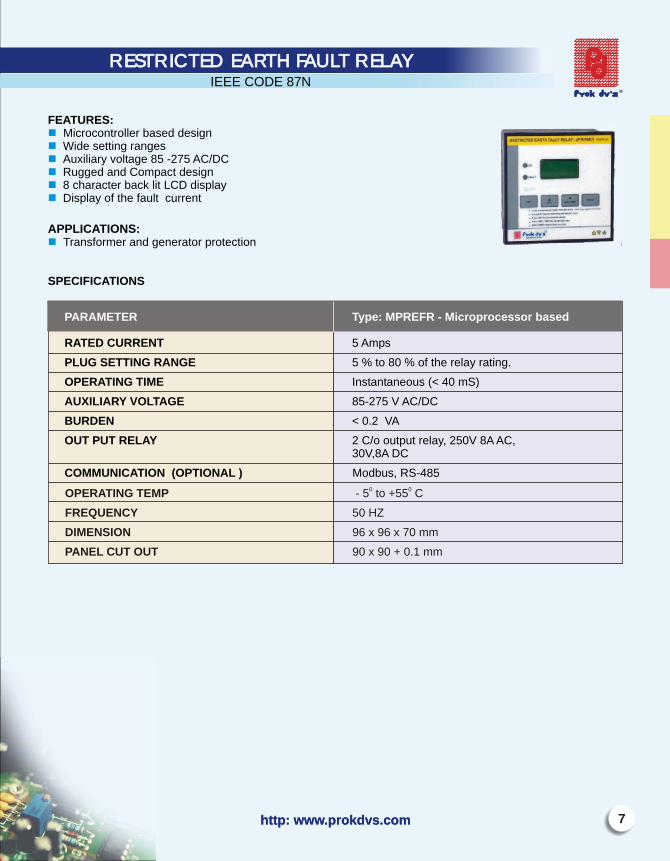
FEATURES:Microcontroller based design Wide setting ranges Auxiliary voltage 85 -275 AC/DCRugged and Compact design 8 character back lit LCD display Display of the fault current
APPLICATIONS:
Transformer and generator protection
SPECIFICATIONS
nnnnnn
n
7http: www.prokdvs.com
RESTRICTED EARTH FAULT RELAY RESTRICTED EARTH FAULT RELAY IEEE CODE 87N
PARAMETER Type: MPREFR - Microprocessor based
RATED CURRENT 5 Amps
PLUG SETTING RANGE 5 % to 80 % of the relay rating.
OPERATING TIME Instantaneous (< 40 mS)
AUXILIARY VOLTAGE 85-275 V AC/DC
BURDEN < 0.2 VA
OUT PUT RELAY 2 C/o output relay, 250V 8A AC,30V,8A DC
COMMUNICATION (OPTIONAL ) Modbus, RS-4850 0OPERATING TEMP - 5 to +55 C
FREQUENCY 50 HZ
DIMENSION 96 x 96 x 70 mm
PANEL CUT OUT 90 x 90 + 0.1 mm

E-mail: [email protected]
SPECIFICATIONS
FEATURES:
Compact IDMT (4 IEC curves) & Definite timeWide setting ranges Fully digital acquisition of dataLCD display of operated currentTropicalized and rugged design
APPLICATIONS
Feeder/Distributor control panelGenerator control panel
nnnnnn
nn
OVER CURRENT RELAY TYPE : MPOCSPLIEEE Device code-50
OVER CURRENT RELAY TYPE : MPOCSPL
PARAMETER MPOCSPL/DMPOCSPL Microprocessor Based
RATED CURRENT 1A or 5 A
IDMT CURVES (IEC) IDMT(NI,3.0 SEC,1.3SEC & LTD) & Definite time / Instantaneous
PLUG SETTING RANGE 50% - 200% in steps of 5%
TMS 0.1 to 2.0 insteps of 0.05
DEFINITE TIME 00.00 to 20.00secInsteps of 00.10sec
INSTANTANEOUS TIME <40ms
RATED FREQUENCY 50Hz
BURDEN ON CT <0.2VA
AUXILIARY VOLTAGE 85-275V AC/DC
RELAY OUTPUT 2 C/O 250 V , 8A AC 30 V 8A DC
OPERATING TEMPERATURE -5 ° C to +55° C
MOUNTING Flush/ Din rail
DIMENSIONS IN MM FLUSH:96X96X70 mm DIN:75X95X75 mm
(WXHXD)
PANEL CUTOUT IN MM 90X90+0.1mm

FEATURES:IDMT & Definite time characteristicsNegative phase sequence detectionHigh Pickup/drop off ratioModular Integrated raw ut ystemNonvolatile memory for data retentionWide range of system voltagesHigh speed feature for under voltages and over voltages2 line,16 character back lit LCD display and key pad.Very low burden on measurement and Aux circuitsAccurate and reliable measurement of voltagesField selectable system voltages
APPLICATIONS: Protection of motor and generatorsMain or backup protectionFor detection of OV& UV in power plants and distribution systemProtection of transformer panel & Capacitor control panel
TRIPPING CHARACTERISTICS: 1.0) IDMT: Over Voltage - t = k / log (ovf) Sec
Under voltage - t = k / log (2-uvf) SecK = time dial setting with range 0.1 to 1.0 Sec in steps of 0.1Ovf = (measured value/set value )x rated voltageUvf = (measured value/ set value) x rated voltage
2.0) Definite Time : (0-300) Sec ( time setting) in steps of 1 sec.
nnnnnnnnnnn
nnnn
D O S
9http: www.prokdvs.com
Numerical Over and Under Voltage relayNumerical Over and Under Voltage relay
Parameter type : PNV NSP
SYSTEM VOLTAGE 380V,400V,415V & 433V- 3Ph 4W
FREQUENCY RANGE 45Hz to 65Hz.
PICK - UP Over Voltage- 101% of set valueUnder Voltage-99% of set value
DROP- OUT Over Voltage 1% below pick- up voltageUnder Voltage-1% above pick -up voltage
RESPONSE TIME < 100ms
SETTING RANGE Under Voltage: Uv< 0.99 to 0.50 Un in steps of 0.01 Uv< <0.99 to 0.50 Un in steps of 0.01(High set)
Over Voltage: Ov> 1.01 to 1.30 Un in steps of 0.01 Ov> >1.01 to 1.30 Un in steps of 0.01(High set)
% OF NEGATIVE SEQUENCE (1-25%) in steps of 1%
NEGATIVE SEQUENCE DEFINITE TIME (0-300) in steps of 1sec
NEGATIVE SEQUENCE INSTANTANEOUS (0.0 -5.0 Sec) in steps of 0.1TIME (NS>>) FOR >25%
TIME FOR HIGH SET (UV<< & OV>>) (0.0 -5.0 Sec) in steps of 0.1
SPECIFICATIONS
SPECIFICATIONS
E-mail: [email protected]
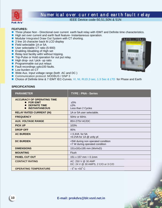
FEATURES:Three phase Non - Directional over current earth fault relay with IDMT and Definite time characteristics.High set over current and earth fault feature- Instantaneous operation.Modular raw ut ystem with CT shorting.2 line 16 character back lit LCD displayField selectable 1A or 5A.User selectable CT ratio (5-900)Enabling /disabling of High setRelay test facility with/ without tripping.Trip-Pulse or Hold operation for out put relay.High drop out / pick up ratioProgrammable out put relaysFault recordings upto100 faults.Low burden on CTWide Aux. Input voltage range (both AC and DC )
Choice of Definite time & 7 IDMT IEC-Curves for Phase and Earth
nnnnnnnnnn nnnnnn , VI, NI, RI,EI,3 sec, 1.3 Sec & LTD
Integrated D O S
- -
Communication protocol: MODBUS / DNP 3
IEEE Device code-50,51,50N & 51N
Numerical over current and earth fault relay Numerical over current and earth fault relay
PARAMETER TYPE : PNA - Series
ACCURACY OF OPERATING TIMEl FOR IDMT ±5%l DEFINITE TIME ±3%
l INSTANTANEOUS Less than 2 Cycles
RELAY RATED CURRENT (IN) 1A or 5A user selectable.
FREQUENCY 50Hz or 60Hz.
AUX. VOLTAGE RANGE 85V-275V AC/DC
PICK UP 103%
DROP OFF 95%
AC BURDEN < 0.4VA for 5A<0.2VA for 1A @ unity pf.
DC BURDEN <5W during non operated condition<7 W during operated condition
DIMENSIONS 151x181x195 mm (WxHxD)
MOUNTING Flush
PANEL CUT OUT 151 x 157 mm + 0.1mm
CONTACT RATING AC: 250 V @ 30 AMP DC: 24 V @ 30 AMPS, 2 C/O or 3 C/O
0 0OPERATING TEMPERATURE - 5 to +55 C

11http: www.prokdvs.com
IEEE Device code-50,51,50N & 51N
Numerical over current and earth fault relay Numerical over current and earth fault relay
Definite Time plug and time settings.
I> phase (0.5-2.0)In 0.01 ( 1-160) Sec 0.1
Ie> Earth (0.05-0.8)In 0.01 ( 1-160) Sec 0.1
Low set (I>) Setting range Step Time setting range Step
RELAY PLUG SETTING RANGES:
Low set range (IDMT)
I> (0.5 to2.0)In. 0.01 t> (0.01-1.6) 0.01
Ie> (0.05 to0.80)In 0.01 t> (0.01-1.6) 0.01
High set range
I>> Phase (2-30)In 0.1 t>> phase (0.0-1.6)Sec 0.1
Ie>> Earth (0.5-16)In 0.1 t>> earth (0.0-1.6)Sec 0.1
Low Set Current(I>) Setting Range Step TMS TMS range TMS Step
High set current (I>>) Setting range Step Time Range Step
E-mail: [email protected]
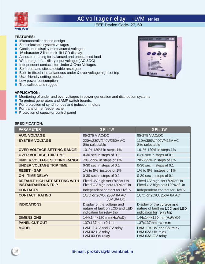
FEATURES: Microcontroller based designSite selectable system voltagesContinuous display of measured voltages16 character 2 line back lit LCD displayAccurate reading for balanced and unbalanced loadWide range of auxiliary input voltages( AC &DC)Independent contacts for Under & Over VoltagesSelf reset and site selectable reset gapBuilt in (fixed ) instantaneous under & over voltage high set tripUser friendly setting modesLow power consumptionTropicalized and rugged
APPLICATION:Monitoring of under and over voltages in power generation and distribution systemsTo protect generators and AMF switch boards.For protection of synchronous and induction motorsFor transformer feeder panelProtection of capacitor control panel
nnnn -nnnnnnnn
nnnnn
SPECIFICATION:
AUX. VOLTAGE 85-275 V AC/DC 85-275 V AC/DC
SYSTEM VOLTAGE 220V/230V/240V/250V AC 110V/380V/400V/415V AC Site selectable Site selectable
OVER VOLTAGE SETTING RANGE 101%-120% in steps 1% 101%-120% in steps 1%
OVER VOLTAGE TRIP TIME 0-30 sec in steps of 0.1 0-30 sec in steps of 0.1
UNDER VOLTAGE SETTING RANGE 70%-99% in steps of 1% 70%-99% in steps of 1%
UNDER VOLTAGE TRIP TIME 0-30 sec in steps of 0.1 0-30 sec in steps of 0.1
RESET - GAP 1% to 5% insteps of 1% 1% to 5% insteps of 1%
ON - TIME DELAY 0-30 sec in steps of 0.1 0-30 sec in steps of 0.1
DEFAULT HIGH SET SETTING WITH Fixed UV high set<70%of Un Fixed UV high set<70%of UnINSTANTANEOUS TRIP Fixed OV high set>120%of Un Fixed OV high set>120%of Un
CONTACTS Independent contact for Uv/Ov Independent contact for Uv/Ov
CONTACT RATING 1C/O or 2C/O, 250V 8A AC 1C/O or 2C/O, 250V 8A AC 30V ,8A DC
INDICATIONS Display of the voltage and Display of the voltage andnature of fault on LCD and LED nature of fault on LCD and LEDindication for relay trip indication for relay trip
DIMENSIONS 144x144x120 mm(HxWxD) 144x144x120 mm(HxWxD)
PANEL CUT OUT 137x137mm +0.1mm 137x137mm +0.1mm
MODEL LVM 11-UV and OV relay LVM 11A-UV and OV relayLVM 02 UV relay LVM 02A UV relayLVM 03-OV relay LVM 03A-OV relay
PARAMETER 3 Ph.4W 3 Ph. 3W
AC voltage relay - LVM seriesAC voltage relay - LVM series
IEEE Device Code- 27, 59
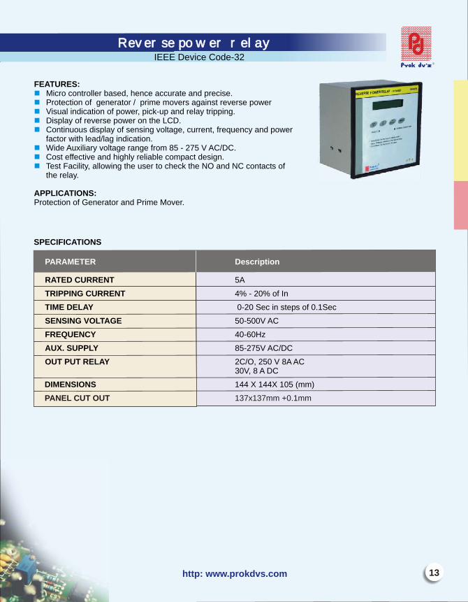
E TU SF A RE :Mi ro c tr l r as , h e c r an r i ec on o le b ed enc ac u ate d p ec s .P ot ti of er tor / p i mo er i t rev e pr ec on gen a r me v s aga ns ers owerV s l ndi a on ower c - p a r a tr p ngi ua i c ti of p , pi k u nd el y i pi .Di pl e s owe on LCD.s ay of rev r e p r theCon nu d s ay of s ns ng ol ag r nt, e c a owe ti ous i pl e i v t e, cur e fr quen y nd p rfa tor wi e a nd c oc th l ad/l g i i ati n. W de u i y t r ge o - 75 Ai A x liar vol age an fr m 85 2 V C/DC.Co ef ti e hi hl r l abl c p t d i .st fec v and g y e i e om ac es gnT s i i l wi he er to c ec NC c t t oe t Fac l ty, al o ng t us h k the NO and on ac s f th ay.e rel
P I A NSAP L C TIO :r tec o f G er tor an r m vP o ti n o en a d P i e Mo er.
nnnnn
nnn
31http: www.prokdvs.com
Reverse power relayReverse power relay
ARAMETE Descr tionP R ip
A ED CU NT 5AR T RRE
TRIP ING RRENT 4% - 0% f InP CU 2 o
TIME DELAY 0-20 Sec in teps 0.1Sec s of
SENSING VOLTAGE 50-500V AC
FREQUENCY 40-60Hz
AUX SUPP Y 85-275V AC/DC. L
OUT UT RELA 2C/O, 0 V 8A AC P Y 25 30V, 8 A DC
ENSI NS 144 X 4X 105 mmDIM O 14 ( )
ANEL CUT UT 137x 37mm +0.1mP O 1 m
SPECIFICATIONS
IEEE Device Code-32

E-mail: [email protected]
FEATURES:
·Microcontroller basedAccurate, reliable and tropicalized designContinuous display of frequencyWide frequency setting rangeWide tripping time rangeWide Aux. input voltage range 85-275 V AC/DC
APPLICATION:
·Generator and captive power plantAs backup protection for mechanical over speed devices to avoid damage to prime moverUnder frequency protection for field winding from excessive current and voltage regulator from over loadServo controllers and invertors
nnnnnn
nn
n
n
Frequency relay Frequency relay
PARAMETER Type : HI-LO
RATED VOLTAGE 230V AC
AUX. SUPPLY 85V-275V AC/DC
FREQUENCY RANGE 40Hz-60Hz insteps of 0.1Hz
POWER SUPPLY BURDEN <3Watts
CONTACTS 250V 8A AC
30V 8A DC Single Change Over
TURN OFF DELAY 0.05 -10 Sec step size 0.05 SecDefinite time
MOUNTING Flush
DIMENSIONS 144x144x120mm
PANEL CUT OUT 137x137mm + 0.1 mm
SPECIFICATIONS
IEEE CODE : 81

APPLICATIONS:
Industrial applications power factor to be maintained at set valueApplications where energy conservation is vital.
To improve system efficency & to avoid PF penalty.
n
n
, Commercial - is Critical &target
15http: www.prokdvs.com
Intelligent power factor correction relay (IPFC)Intelligent power factor correction relay (IPFC)IEEE- Device code-55
SPECIFICATIONS
PARAMETER IPFC
MEASUREMENT True RMS
P.F RANGE 0.8 lag to 0.9lead
RECONNECTION TIME OF THE SAME CAPACITOR BANK 5-150 sec
RATED CURRENT 5A
APACITOR KVAR Auto Detection of KVAR
CT RATIO Manual entry
SWITCHING DELAY programmable
CT POLARITY DETECTION Auto Detection
STAGES 4,6,8,10 &12 stage
OPERATING LIMIT OF CURRENT 0.125 to 6A
OVER LOAD +20 %Ib
SHORT TIME WITH STAND CURRENT 5 Ib for 1Sec.
POWER CONSUMPTION 0.65W
AUX. SUPPLY 230V, 50HZ ±20%
FREQUENCY 50 Hz / 60Hz.
QUADRANT OPERATION 4quadrant operation
LOCK OUT TIME FOLLOWING POWER FAILURE 90 sec lock out time
FAILURE ALARM FOR FAILURE TO ACHIEVE TARGET P.F After 75 switching cycle
ALARM FOR EXCESSIVE HARMONIC DISTURBANCE available
DISPLAY OF VARIOUS PARAMETERS(LCD) Voltage, current, frequency phase angle, cos phi, kva kvar
SERIAL COMMUNICATION RS-485 port Mmodbus protocolDevice ID (1-31)
AUTO/MANUAL OPERATION Yes
OUT PUT RELAY RATING 1C/O, 250V,8A AC, 30V, 8A DC
DIMENSIONS 144 X 144 X 105mm
PANEL CUT OUT 137 X 137 + 0.1mm

Voltage monitoring devices - Volt pro seriesVoltage monitoring devices - Volt pro series
IEEE Device Code- 27,47,59
E-mail: [email protected]
FEATURES:
MPVR Series (µP BASED) VD Series SOLID STATEAccurate Measurements Solid State CircuitryNegative Phase Sequence Detection Negative Phase Sequence Detection Fixed or Variable ime elay Fixed or Variable ime elay8 Char. 2line LCD back lit display Auto ResetAuto Reset Fail afe mechanismFlush/Din rail mounting Din ail ountingLCD indication of Healthy ,Operated LED indication of Healthy & Fault Voltages & Phase ail / hase eversalRS-485 com port.(Optional)
APPLICATIONS
Protection of Synchronous and Induction Motor of any HP ratingProtection of enerators, AMF witch oardTransformer eeder anelDistribution oardsVoltage egulatorsProtection of UPS & ingle hase pplication
n nn nn nn nn nn nn nnn
nnnnnn
T D T D
SR M
F P R
G S BF P
BR
S P A
TYPE VD series Models (Solid State) TYPE MPVR Series Models (µP Based Models)
VD-02 l UV/OV & Ph .fail /Ph. Revs. MPVR-02 l OV(105%-120% of Un )l 100mSec Tripping Time for OV,UV. l UV ( 80%-95% of Un)
l Ph .fail /Ph. Rev,.
VD-03 l UV/OV & Ph .fail /Ph. Revs MPVR-03 l OV(105%-120% of Un ) with Time Delay Trip time ( 0-15) sec l UV ( 80%-95% of Un)
l Trip Time Delay-( 0.5-20) Secl Ph .fail /Ph. Rev.
VD-04 l UV/OV Single Ph MPVR-04 l Single Phasel UV- (160 V-210 V) Step- 10 V l Reset gap-5Vto 20Vl OV-(240V-290V) Step- 10 V l UV- 160V to 210V, step 1% of 230V
l OV- 240V to 290V, step1% of 230Vl UV/OV- Trip Time Delay ( 0.5-20) Sec
VD-05 l UV With Ph. Fail/Phase Rev MPVR-05 l UV-(80%-95% of Un) with time delay Trip time ( 0-15) Sec l Trip Time Delay-( 0.5-20) Sec
l
VD-06 l OV With Ph. Fail/Phase Rev MPVR-06 l OV (105%-120% of Un) with time delay Trip time ( 0-15) Sec l Trip delay-( 0.5-20) Sec
l Ph .fail /Ph. Rev
VD-07 l 90% of Un Fixed UV with Ph. Fail/Ph. MPVR-07 l 90%(Un) Fixed Under Voltage Rev with time delay Trip time ( 0-15) Sec l Trip Time Delay-( 0.5-20) Sec
l Ph .fail /Ph. Rev
Ph .fail /Ph. Rev
SPECIFICATIONS:
http: www.prokdvs.com 17
SPECIFICATIONS:
SYSTEM VOLTAGE 415VAC±20%,50Hz. 3Ø 4W 415V AC ± 20% 50Hz, 3Ø 3W
SENSING AUX. VOLTAGE(UN) 110V/230V/415V AC 20%,50Hz
AUXILIARY VOLTAGE 85-275V AC/DC NA
CONTACTS & RATING: 2 C/O contacts,250V 8 A AC 2 C/O contacts,250V 8 A AC30V,8A DC 30V,8A DC
TRIP VOLTAGE SETTINGS:A)UNDER VOLTAGE 80%-95% of Un Step-1% 80%-95% of Un Step- 3%B)OVER VOLTAGE 105%-120% of Un Step-1% 105%-120% of Un Step- 3%C)PHASE TO PHASE UNBALANCE NA 100V fixed
TRIP TIME DELAYA)PHASE FAIL/PHASE REVERSAL Approx: 2Sec 3Sec - Fixed.B)UNDER/OVER VOLTAGE 0.5-20 Sec, Step-0.5Sec 0-15 Sec ,Step 3Sec
100msec Fixed(Depends on model)
ON - TIME DELAY 0.5 -10Sec, Step size 0.5Sec 3 Sec Fixed.
RESET GAP(MAX):A)UNDER/OVER VOLTAGE 5-20V Step-5V NAB)UNBALANCE VOLTAGE 10V ± 2V 5-10V
RESETTING MODE Auto Auto
INDICATION:A)GREEN LED 1) Phase Fail / Phase Reversal System HealthyB)RED LED 2) Under Voltage trip indication 1) Phase Fai l /Phase
3) Over Voltage trip indication Reversal / Phase Unbalance2) Under Voltage trip indication3) Over Voltage trip indication
INDICATION:LCD
l Phase Voltages ·l Phase Reversall Phase Failure NAl OV/UV Trip Value Indication.
MOUNTING Din & Flush Din mounting
POWER CONSUMPTION <4VA <4VA
INSULATION 2KV, 50Hz for 1min 2KV, 50Hz for 1min.
DIMENSIONA)FLUSH 96*96*70mm(W*H*D) NAB)DIN 80*94*75mm(W*H*D) (75 * 95*75mm)-Din
MODELS: MPVR-02,MPVR-03 ,MPVR-04 VD-02. VD-03 VD-04MPVR-05,MPVR-06,MPVR-07 VD-05,VD-06,VD-07
PARAMETER Type : MPVR Series (µP based) VD series (Solid State)
110V/230V/415V AC 20%,50Hz
DISPLAY :
OPERATING TEMP -5° C to +55° C -5° C to +55° C
Voltage monitoring devicesVoltage monitoring devicesIEEE Device Code- 27,47,59

E-mail: [email protected]
FEATURES:Phase eversal etectionLow ower onsumptionSelectable percentage nbalance ettingsAuto / anual eset Fail afe ystemAccurate, eliable and ropicalized esignDin ounting
APPLICATIONS
Suitable for Motors of any HP ratingPower supply istribution oardsAgriculture ump ontrol anels
nnnnnnn
nnn
R DP C
U S M RS S
R T DM
D BP C P
SPECIFICATION:
PARAMETER PHASE PHEE
SYSTEM VOLTAGE(UN) 415V AC 50 Hz 3 Phase.
TRIPPING DELAY 2.5 sec (Fixed)
UNBALANCED VOLTAGE SETTING 10% or 20% of Un
RESET Manual/Auto
AUXILIARY VOLTAGE 110 / 230 / 415 VAC 50 Hz
RELAY CONTACTS 2C/O potential free contacts250V 8A AC , 30 V 8 A DC
DIMENSIONS 75x95x75mm
MOUNTING Din
OPERATING TEMP -5° C to +55° C
Phase failure relay TYPE: PHASE PHEE Phase failure relay TYPE: PHASE PHEE
IEEE Device code-47
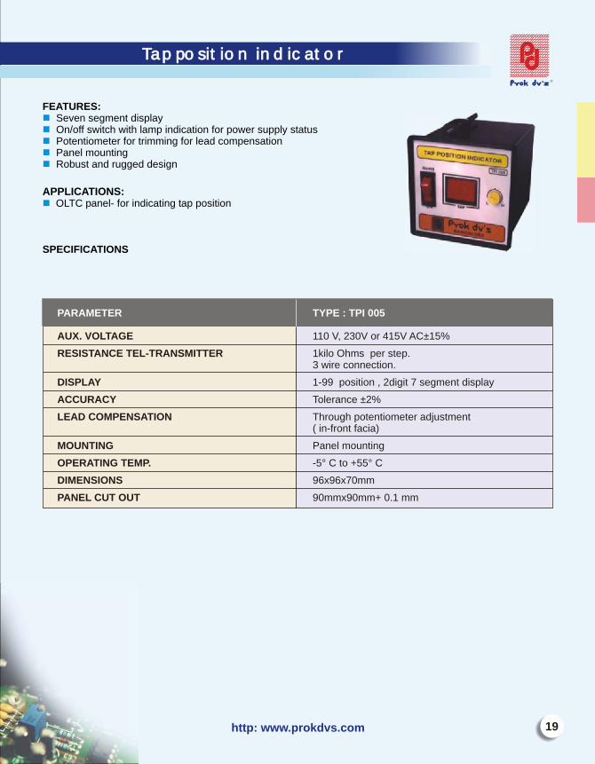
FEATURES:Seven segment displayOn/off switch with lamp indication for power supply statusPotentiometer for trimming for lead compensationPanel mountingRobust and rugged design
APPLICATIONS:
OLTC panel- for indicating tap position
SPECIFICATIONS
nnnnn
n
19http: www.prokdvs.com
Tap position indicator Tap position indicatorIEEE CODE 87N
PARAMETER TYPE : TPI 005
AUX. VOLTAGE 110 V, 230V or 415V AC±15%
RESISTANCE TEL-TRANSMITTER 1kilo Ohms per step.3 wire connection.
DISPLAY 1-99 position , 2digit 7 segment display
ACCURACY Tolerance ±2%
LEAD COMPENSATION Through potentiometer adjustment( in-front facia)
MOUNTING Panel mounting
OPERATING TEMP.
DIMENSIONS 96x96x70mm
PANEL CUT OUT 90mmx90mm+ 0.1 mm
-5° C to +55° C
E-mail: [email protected]
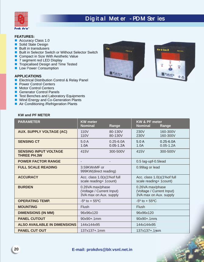
FEATURES:Accuracy Class 1.0Solid tate esignBuilt in transdusersBuilt in Selector Switch or Without Selector SwitchCompact in Size With Aesthetic Value7 segment red LED DisplayTropicalised Design and ime estedLow ower onsumption
APPLICATIONS
Electrical Distribution Control & Relay PanelPower Control CentersMotor Control CentersGenerator Control PanelsTest Benches and Laboratory EquipmentsWind Energy and Co-Generation PlantsAir Conditioning /Refrigeration Plants
nnnnnnnn
nnnnnnn
S D
T TP C
Digital Meter - PDM SeriesDigital Meter - PDM Series
20
KW and PF METER
AUX. SUPPLY VOLTAGE (AC) 110V 80-130V 230V 160-300V110V 80-130V 230V 160-300V
SENSING CT 5.0 A 0.25-6.0A1.0A 0.05-1.2A
SENSING INPUT VOLTAGE 415V 300-500V 415V 300-500VTHREE PH.3W
POWER FACTOR RANGE - - 0.5 lag-upf-0.5lead
FULL SCALE READING 3.59KWxMF or 0.99lag or lead999KW(direct reading)
ACCURACY Acc. class 1.0(±(1%of full Acc. class 1.0(±(1%of fullscale reading+ 1count) scale reading+ 1count)
BURDEN 0.26VA max/phase 0.26VA max/phase(Voltage / Current Input) (Voltage / Current Input)3VA max on Aux. supply 3VA max on Aux. supply
OPERATING TEMP. -5º to + 55ºC -5º to + 55ºC
MOUNTING Flush Flush
DIMENSIONS (IN MM) 96x96x120 96x96x120
PANEL CUTOUT 90x90+.1mm 90x90+.1mm
ALSO AVAILABLE IN DIMENSIONS 144x144x95 144x144x95
PANEL CUT OUT 137x137+.1mm 137x137+.1mm
PARAMETER KW meter KW & PF meterNominal Range Nominal Range
5.0 A 0.25-6.0A1.0A 0.05-1.2A
21http: www.prokdvs.com
Digital Meter - PDM SeriesDigital Meter - PDM Series
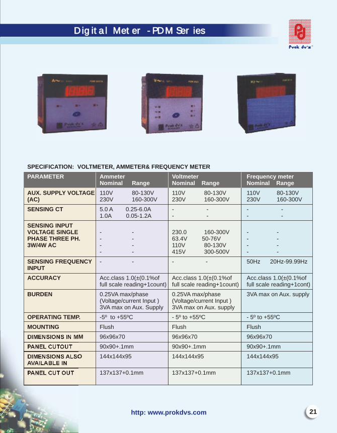
SPECIFICATION: VOLTMETER, AMMETER& FREQUENCY METER
AUX. SUPPLY VOLTAGE 110V 80-130V 110V 80-130V 110V 80-130V(AC) 230V 160-300V 230V 160-300V 230V 160-300V
SENSING CT 5.0 A 0.25-6.0A - - - -1.0A 0.05-1.2A - - - -
SENSING INPUT VOLTAGE SINGLE - - 230.0 160-300V - -PHASE THREE PH. - - 63.4V 50-76V - -3W/4W AC - - 110V 80-130V - -
- - 415V 300-500V - -
SENSING FREQUENCY - - - - 50Hz 20Hz-99.99HzINPUT
ACCURACY Acc.class 1.0(±(0.1%of Acc.class 1.0(±(0.1%of Acc.class 1.0(±(0.1%offull scale reading+1count) full scale reading+1count) full scale reading+1cont)
BURDEN 0.25VA max/phase 0.25VA max/phase 3VA max on Aux. supply(Voltage/current Input ) (Voltage/current Input )3VA max on Aux. Supply 3VA max on Aux. supply
OPERATING TEMP. -5º to +55ºC - 5º to +55ºC - 5º to +55ºC
MOUNTING Flush Flush Flush
DIMENSIONS IN MM 96x96x70 96x96x70 96x96x70
PANEL CUTOUT 90x90+.1mm 90x90+.1mm 90x90+.1mm
DIMENSIONS ALSO 144x144x95 144x144x95 144x144x95AVAILABLE IN
PANEL CUT OUT 137x137+0.1mm 137x137+0.1mm 137x137+0.1mm
PARAMETER Ammeter Voltmeter Frequency meterNominal Range Nominal Range Nominal Range
E-mail: [email protected]
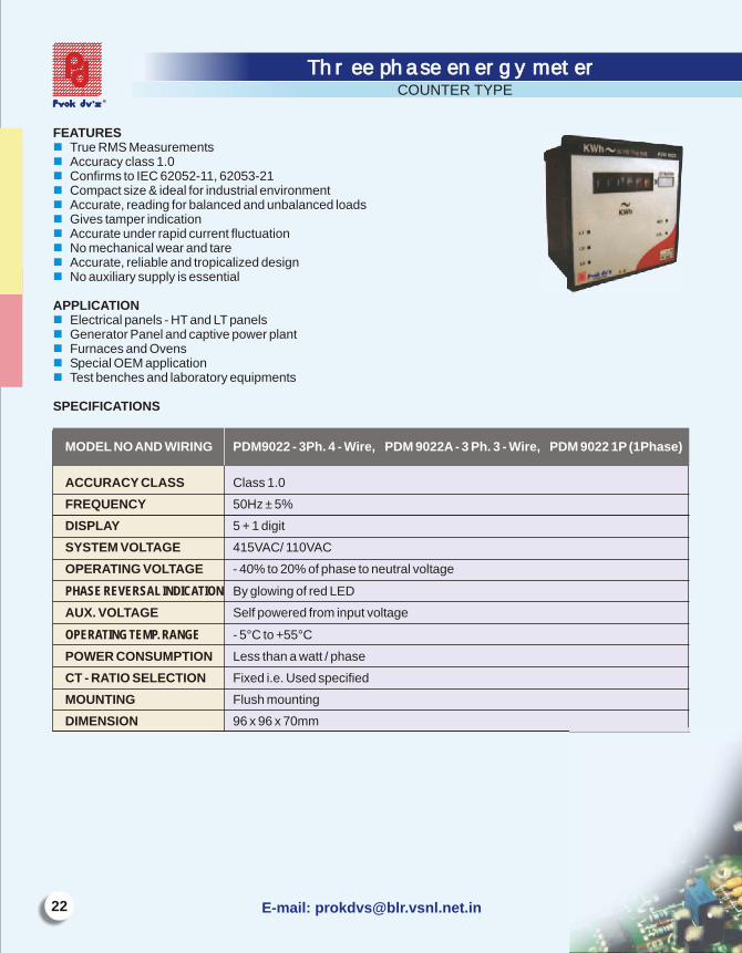
FEATURESTrue RMS MeasurementsAccuracy class 1.0Confirms to IEC 62052-11, 62053-21 Compact size & ideal for industrial environmentAccurate, reading for balanced and unbalanced loadsGives tamper indicationAccurate under rapid current fluctuationNo mechanical wear and tareAccurate, reliable and tropicalized designNo auxiliary supply is essential
APPLICATIONElectrical panels - HT and LT panelsGenerator Panel and captive power plantFurnaces and OvensSpecial OEM applicationTest benches and laboratory equipments
SPECIFICATIONS
nnnnnnnnnn
nnnnn
Three phase energy meterThree phase energy meter
ACCURACY CLASS Class 1.0
FREQUENCY 50Hz ± 5%
DISPLAY 5 + 1 digit
SYSTEM VOLTAGE 415VAC/ 110VAC
OPERATING VOLTAGE - 40% to 20% of phase to neutral voltage
PHASE REVERSAL INDICATION By glowing of red LED
AUX. VOLTAGE Self powered from input voltage
OPERATING TEMP. RANGE - 5°C to +55°C
POWER CONSUMPTION Less than a watt / phase
CT - RATIO SELECTION Fixed i.e. Used specified
MOUNTING Flush mounting
DIMENSION 96 x 96 x 70mm
MODEL NO AND WIRING PDM9022 - 3Ph. 4 - Wire, PDM 9022A - 3 Ph. 3 - Wire, PDM 9022 1P (1Phase)
COUNTER TYPE

23http: www.prokdvs.com
FEATURES:
APPLICATIONS
FEATURES:
nnnnnnnnnnnnn
nnnnn
IEC 62052-11, 62053-21
2 line 16 character
True RMS MeasurementsAccuracy class 1.0Continuous display of the measured - KWHUser selectable CT - ratioConfirms to Compact size & ideal for industrial environmentAccurate reading for balanced and unbalanced loads
back lit LCD displayGives tamper indicationAccurate under rapid current fluctuationDirect reading-CT operatedNo mechanical wear and tareAccurate, reliable and tropicalized design
Electrical panels - HT and LT panelsGenerator Panel and captive power plantFurnaces and OvensSpecial OEM applicationTest benches and laboratory equipments
make PDM - series is the state of the art Three Phase Energy Meter. It uses reliable solid state along with Micro controller and non-volatile memory. All measurements fall with in the accuracy class of 1.0. The design incorporates anti tamper features, which makes the meter dependable in field use. Satisfactory operation is guaranteed in the frequency range %. CT ratio are field programmable. The design is tropicalised and rugged.
50HZ ±5
Three phase energy meterThree phase energy meterLCD TYPE
R
MODEL NO. AND WRING PDM9023-3Ph. 4-Wire, PDM9023A-3PH. 3-Wire, PDM9023RS-RS-485 port3PH 4 Wire, PDM9023RS-RS-485 port 3PH 3 Wire, PDM9023 1P[1Ø]
ACCURACY CLASS Class 1.0
FREQUENCY 50Hz±5%
DISPLAY 6 + 1digit
SYSTEM VOLTAGE 415VAC/110VAC
OPERATING VOLTAGE -40% to 20% of phase to neutral voltage
PHASE REVERSAL INDICATION By glowing of Red LED
AUX. VOLTAGE 230 VAC ,50 HZ
OPERATING TEMPERATURE RANGE -5° C to +55° C
CT-RATIO RANGE /5A & 1A 5/5A......3000/5A- direct reading range1/1A......1000/1A- direct reading range
CT- RATIO SELECTION Field selectable
MOUNTING Flush mounting
DIMENSION 96X96X70mm
E-mail: [email protected]
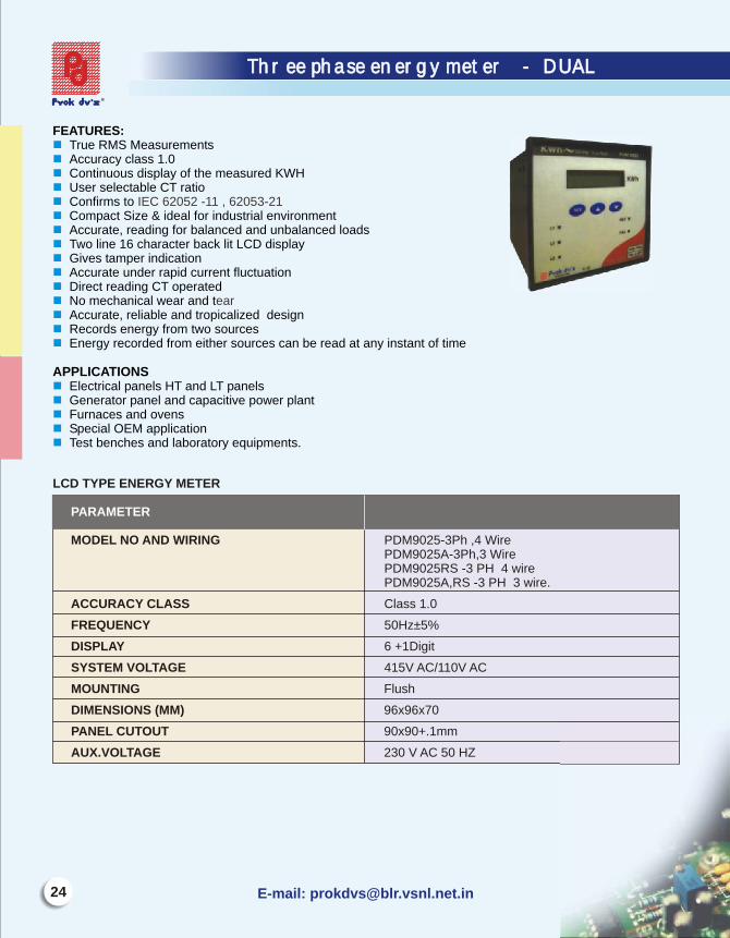
FEATURES:True RMS Measurements Accuracy class 1.0Continuous display of the measured KWHUser selectable CT ratioConfirms to Compact Size & ideal for industrial environment Accurate, reading for balanced and unbalanced loads Two line 16 character back lit LCD displayGives tamper indication Accurate under rapid current fluctuation Direct reading CT operatedNo mechanical wear and t Accurate, reliable and tropicalized design Records energy from two sourcesEnergy recorded from either sources can be read at any instant of time
APPLICATIONS
Electrical panels HT and LT panelsGenerator panel and capacitive power plant Furnaces and ovens Special OEM application Test benches and laboratory equipments.
nnnnnnnnnnnnnnn
nnnnn
IEC 62052 -11 , 62053-21
ear
LCD TYPE ENERGY METER
MODEL NO AND WIRING PDM9025-3Ph ,4 WirePDM9025A-3Ph,3 Wire PDM9025RS -3 PH 4 wire PDM9025A,RS -3 PH 3 wire.
ACCURACY CLASS Class 1.0
FREQUENCY 50Hz±5%
DISPLAY 6 +1Digit
SYSTEM VOLTAGE 415V AC/110V AC
PARAMETER
MOUNTING Flush
DIMENSIONS (MM) 96x96x70
PANEL CUTOUT 90x90+.1mm
AUX.VOLTAGE 230 V AC 50 HZ
IEEE Device code-50,51,50N & 51N
Three phase energy meter - DUAL Three phase energy meter - DUAL
http: www.prokdvs.com
IEEE Device code-50,51,50N & 51N
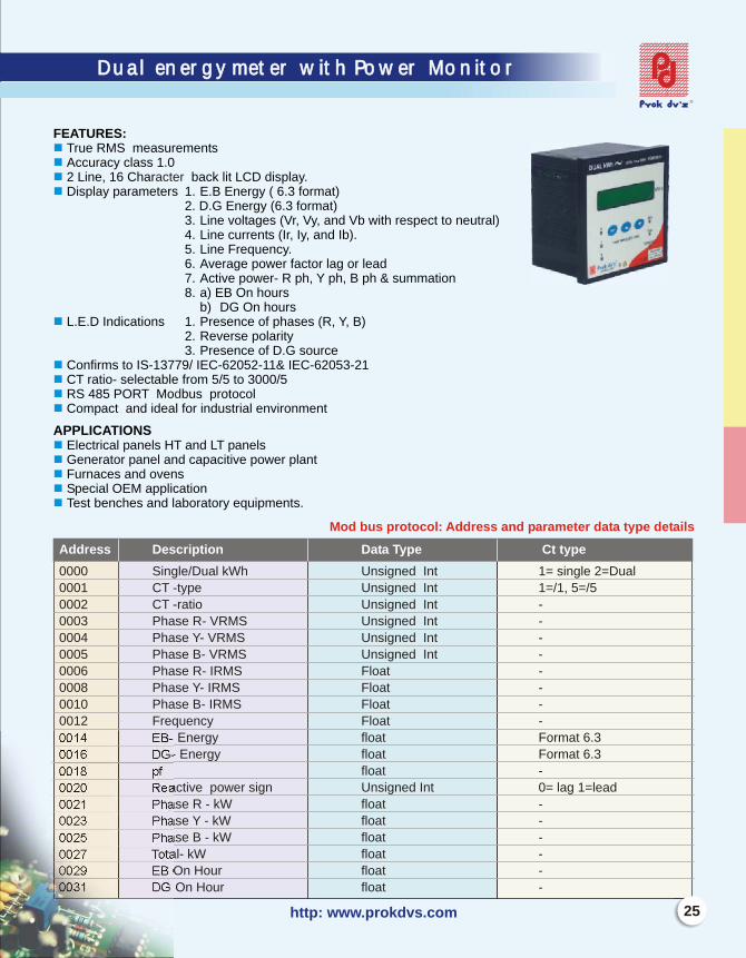
Dual energy meter with Power MonitorDual energy meter with Power Monitor
FEATURES:True RMS measurementsAccuracy class 1.02 Line, 16 Char back lit LCD display.Display parameters 1. E.B Energy ( 6.3 format)
2. D.G Energy (6.3 format)3. Line voltages (Vr, Vy, and Vb with respect to neutral) 4. Line currents (Ir, Iy, and Ib).5. Line Frequency.6. Average power factor lag or lead7. Active power- R ph, Y ph, B ph & summation8. a) EB On hours
b) DG On hoursL.E.D Indications 1. Presence of phases (R, Y, B)
2. Reverse polarity 3. Presence of D.G source
Confirms to IS-13779/ IEC-62052-11& IEC-62053-21CT ratio- selectable from 5/5 to 3000/5RS 485 PORT Mo bus protocolCompact and ideal for industrial environment
APPLICATIONS Electrical panels HT and LT panelsGenerator panel and capacitive power plant Furnaces and ovens Special OEM application Test benches and laboratory equipments.
nnnn
n
nnnn
nnnnn
acter
d
Address Description Data Type Ct type
0000 Single/Dual kWh Unsigned Int 1= single 2=Dual
0001 CT -type Unsigned Int 1=/1, 5=/5
0002 CT -ratio Unsigned Int -
0003 Phase R- VRMS Unsigned Int -
0004 Phase Y- VRMS Unsigned Int -
0005 Phase B- VRMS Unsigned Int -
0006 Phase R- IRMS Float -
0008 Phase Y- IRMS Float -
0010 Phase B- IRMS Float -
0012 Frequency Float -
0014 EB- Energy float Format 6.3
0016 DG- Energy float Format 6.3
0018 pf float -
0020 Reactive power sign Unsigned Int 0= lag 1=lead
0021 Phase R - kW float -
0023 Phase Y - kW float -
0025 Phase B - kW float -
0027 Total- kW float -
0029 EB On Hour float -
0031 DG On Hour float -
Mod bus protocol: Address and parameter data type details
25
E-mail: [email protected]
Dual energy meter with Power MonitorDual energy meter with Power Monitor
SPECIFICATIONS
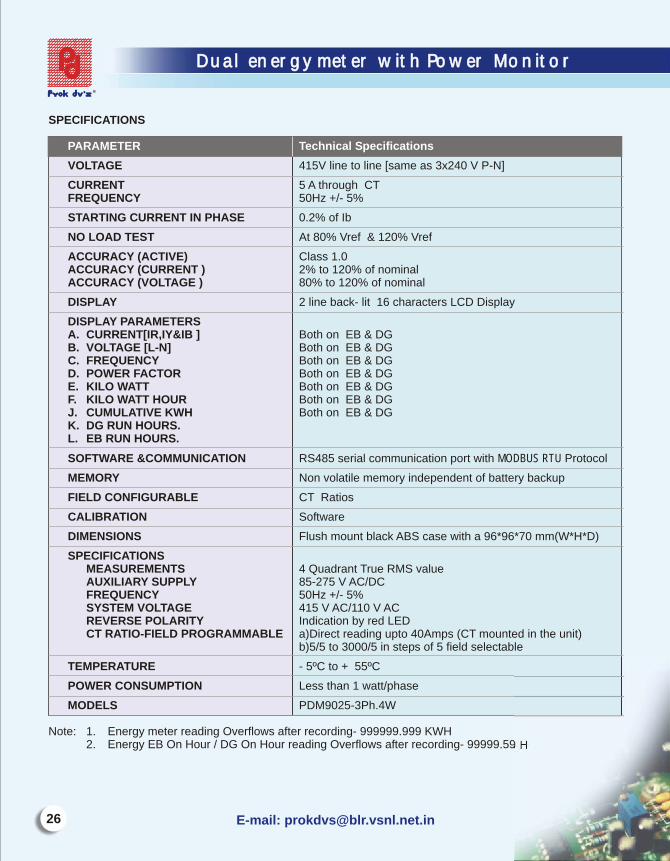
VOLTAGE 415V line to line [same as 3x240 V P-N]
CURRENT 5 A through CTFREQUENCY 50Hz +/- 5%
STARTING CURRENT IN PHASE 0.2% of Ib
NO LOAD TEST At 80% Vref & 120% Vref
ACCURACY (ACTIVE) Class 1.0ACCURACY (CURRENT ) 2% to 120% of nominal ACCURACY (VOLTAGE ) 80% to 120% of nominal
DISPLAY 2 line back- lit 16 characters LCD Display
DISPLAY PARAMETERSA. CURRENT[IR,IY&IB ] Both on EB & DG
B. VOLTAGE [L-N] Both on EB & DGC. FREQUENCY Both on EB & DGD. POWER FACTOR Both on EB & DGE. KILO WATT Both on EB & DGF. KILO WATT HOUR Both on EB & DGJ. CUMULATIVE KWH Both on EB & DGK. DG RUN HOURS. L. EB RUN HOURS.
SOFTWARE &COMMUNICATION RS485 serial communication port with MODBUS RTU Protocol
MEMORY Non volatile memory independent of battery backup
FIELD CONFIGURABLE CT Ratios
CALIBRATION Software
DIMENSIONS Flush mount black ABS case with a 96*96*70 mm(W*H*D)
SPECIFICATIONSMEASUREMENTS 4 Quadrant True RMS valueAUXILIARY SUPPLY 85-275 V AC/DCFREQUENCY 50Hz +/- 5%SYSTEM VOLTAGE 415 V AC/110 V ACREVERSE POLARITY Indication by red LEDCT RATIO-FIELD PROGRAMMABLE a)Direct reading upto 40Amps (CT mounted in the unit)
b)5/5 to 3000/5 in steps of 5 field selectable
TEMPERATURE - 5ºC to + 55ºC
POWER CONSUMPTION Less than 1 watt/phase
MODELS PDM9025-3Ph.4W
Note: 1. Energy meter reading Overflows after recording- 999999.999 KWH2. Energy EB On Hour / DG On Hour reading Overflows after recording- 99999.59 H
PARAMETER Technical Specifications
27http: www.prokdvs.com
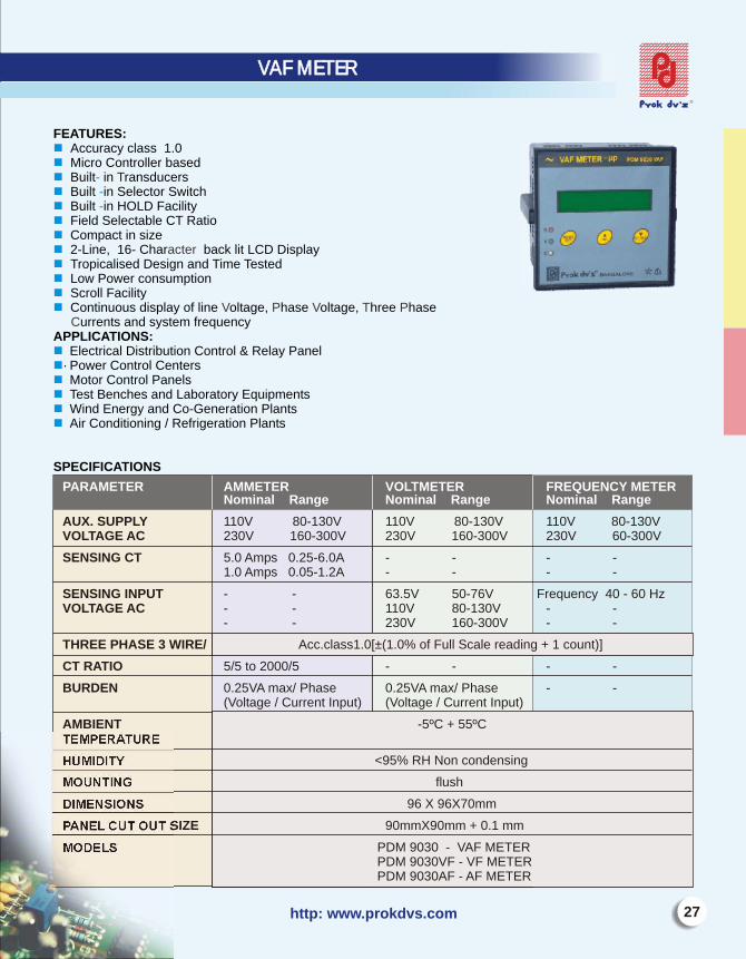
FEATURES: Accuracy class 1.0Micro Controller basedBuilt in ransducersBuilt in Selector SwitchBuilt in HOLD FacilityField Selectable CT RatioCompact in size2-Line, 16- Char back lit LCD DisplayTropicalised Design and Time TestedLow Power consumptionScroll FacilityContinuous display of line oltage, hase oltage, hree hase
urrents and system frequencyAPPLICATIONS:
Electrical Distribution Control & Relay Panel· Power Control CentersMotor Control PanelsTest Benches and Laboratory EquipmentsWind Energy and Co-Generation PlantsAir Conditioning / Refrigeration Plants
SPECIFICATIONS
nnn -n -n -nnnnnnn
nnnnnn
T
acter
V P V T PC
PARAMETER AMMETER VOLTMETER FREQUENCY METER Nominal Range Nominal Range Nominal Range
AUX. SUPPLY 110V 80-130V 110V 80-130V 110V 80-130VVOLTAGE AC 230V 160-300V 230V 160-300V 230V 60-300V
SENSING CT 5.0 Amps 0.25-6.0A - - - -1.0 Amps 0.05-1.2A - - - -
SENSING INPUT - - 63.5V 50-76V Frequency 40 - 60 HzVOLTAGE AC - - 110V 80-130V - -
- - 230V 160-300V - -
THREE PHASE 3 WIRE/ Acc.class1.0[±(1.0% of Full Scale reading + 1 count)]
CT RATIO 5/5 to 2000/5 - - - -
BURDEN 0.25VA max/ Phase 0.25VA max/ Phase - -(Voltage / Current Input) (Voltage / Current Input)
AMBIENT -5ºC + 55ºCTEMPERATURE
HUMIDITY <95% RH Non condensing
MOUNTING flush
DIMENSIONS 96 X 96X70mm
PANEL CUT OUT SIZE 90mmX90mm + 0.1 mm
MODELS PDM 9030 - VAF METER PDM 9030VF - VF METER PDM 9030AF - AF METER
VAF METERVAF METER IEEE Device Code-
E-mail: [email protected]
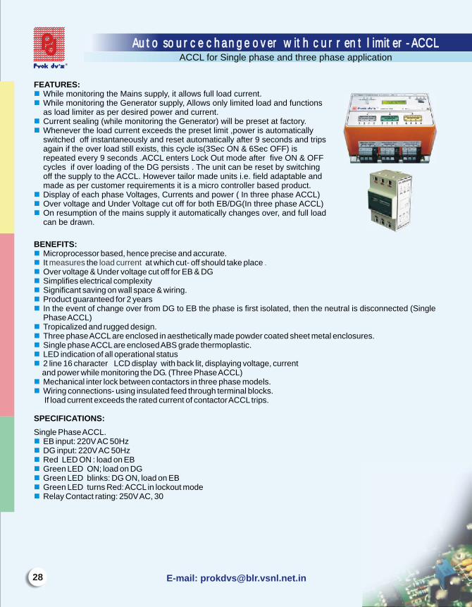
FEATURES:While monitoring the Mains supply, it allows full load current.While monitoring the Generator supply, Allows only limited load and functions as load limiter as per desired power and current.Current sealing (while monitoring the Generator) will be preset at factory.Whenever the load current exceeds the preset limit ,power is automatically switched off instantaneously and reset automatically after 9 seconds and trips again if the over load still exists, this cycle is(3Sec ON & 6Sec OFF) is repeated every 9 seconds .ACCL enters Lock Out mode after five ON & OFF cycles if over loading of the DG persists . The unit can be reset by switching off the supply to the ACCL. However tailor made units i.e. field adaptable and made as per customer requirements it is a micro controller based product. Display of each phase Voltages, Currents and power ( In three phase ACCL)Over voltage and Under Voltage cut off for both EB/DG(In three phase ACCL)On resumption of the mains supply it automatically changes over, and full load can be drawn.
nn
nn
nnn
BENEFITS:Microprocessor based, hence precise and accurate.It the at which cut off should take place Over voltage & Under voltage cut off for EB & DGSimplifies electrical complexity Significant saving on wall space & wiring.Product guaranteed for 2 yearsIn the event of change over from DG to EB the phase is first isolated, then the neutral is disconnected (Single Phase ACCL)Tropicalized and rugged design.Three phase ACCL are enclosed in aesthetically made powder coated sheet metal enclosures.Single phase ACCL are enclosed ABS grade thermoplastic.LED indication of all operational status2 line 16 character LCD display with back lit, displaying voltage, current
and power while monitoring the DG. (Three Phase ACCL)Mechanical inter lock between contactors in three phase models.Wiring connections- using insulated feed through terminal blocks.
If load current exceeds the rated current of contactor ACCL trips.
SPECIFICATIONS:
Single Phase ACCL.EB input: 220V AC 50Hz DG input: 220V AC 50Hz Red LED ON : load on EBGreen LED ON; load on DGGreen LED blinks: DG ON, load on EBGreen LED turns Red: ACCL in lockout modeRelay Contact rating: 250V AC, 30
nn .nnnnn
nnnnn
nn
nnnnnnn
measures load current -
Auto source change over with current limiter- ACCLAuto source change over with current limiter- ACCLACCL for Single phase and three phase application
29http: www.prokdvs.com
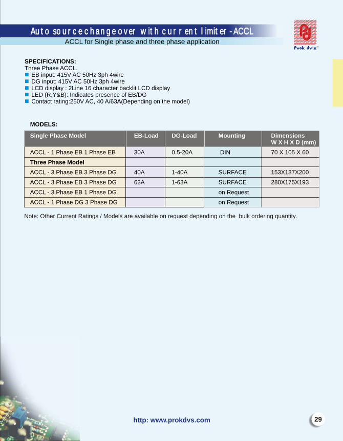
SPECIFICATIONS:Three Phase ACCL.
EB input: 415V AC 50Hz 3ph 4wireDG input: 415V AC 50Hz 3ph 4wireLCD display : 2Line 16 character backlit LCD displayLED (R,Y&B): Indicates presence of EB/DGContact rating:250V AC, 40 A/63A(Depending on the model)
nnnnn
MODELS:
ACCL - 1 Phase EB 1 Phase EB 30A 0.5-20A DIN 70 X 105 X 60
Three Phase Model
ACCL - 3 Phase EB 3 Phase DG 40A 1-40A SURFACE 153X137X200
ACCL - 3 Phase EB 3 Phase DG 63A 1-63A SURFACE 280X175X193
ACCL - 3 Phase EB 1 Phase DG on Request
ACCL - 1 Phase DG 3 Phase DG on Request
Single Phase Model EB-Load DG-Load Mounting DimensionsW X H X D (mm)
Note: Other Current Ratings / Models are available on request depending on the bulk ordering quantity.
Auto source change over with current limiter- ACCLAuto source change over with current limiter- ACCLACCL for Single phase and three phase application
E-mail: [email protected]
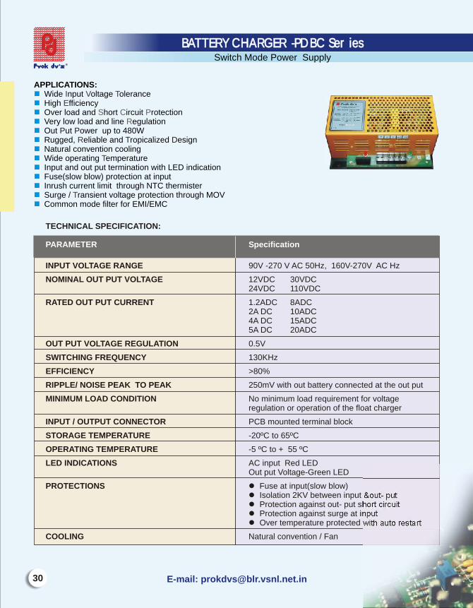
APPLICATIONS:Wide nput oltage oleranceHigh fficiencyOver load and hort ircuit rotectionVery low load and line egulationOut ut ower up to 480WRugged, eliable and ropicalized esignNatural convention coolingWide operating emperature Input and out put termination with LED indicationFuse(slow blow) protection at inputInrush current limit through NTC thermisterSurge / ransient voltage protection through MOVCommon mode filter for EMI/EMC
n nnnnnnnnnnn n
I V TE
R
T
T
S C PR
P PT D
BATTERY CHARGER -PDBC SeriesBATTERY CHARGER -PDBC SeriesSwitch Mode Power Supply
TECHNICAL SPECIFICATION:
INPUT VOLTAGE RANGE 90V -270 V AC 50Hz, 160V-270V AC Hz
NOMINAL OUT PUT VOLTAGE 12VDC 30VDC24VDC 110VDC
RATED OUT PUT CURRENT 1.2ADC 8ADC2A DC 10ADC4A DC 15ADC5A DC 20ADC
OUT PUT VOLTAGE REGULATION 0.5V
SWITCHING FREQUENCY 130KHz
EFFICIENCY >80%
RIPPLE/ NOISE PEAK TO PEAK 250mV with out battery connected at the out put
MINIMUM LOAD CONDITION No minimum load requirement for voltageregulation or operation of the float charger
INPUT / OUTPUT CONNECTOR PCB mounted terminal block
STORAGE TEMPERATURE -20ºC to 65ºC
OPERATING TEMPERATURE -5 ºC to + 55 ºC
LED INDICATIONS AC input Red LEDOut put Voltage-Green LED
PROTECTIONS l Fuse at input(slow blow)l Isolation 2KV between input &out- putl Protection against out- put short circuitl Protection against surge at inputl Over temperature protected with auto restart
COOLING Natural convention / Fan
PARAMETER Specification
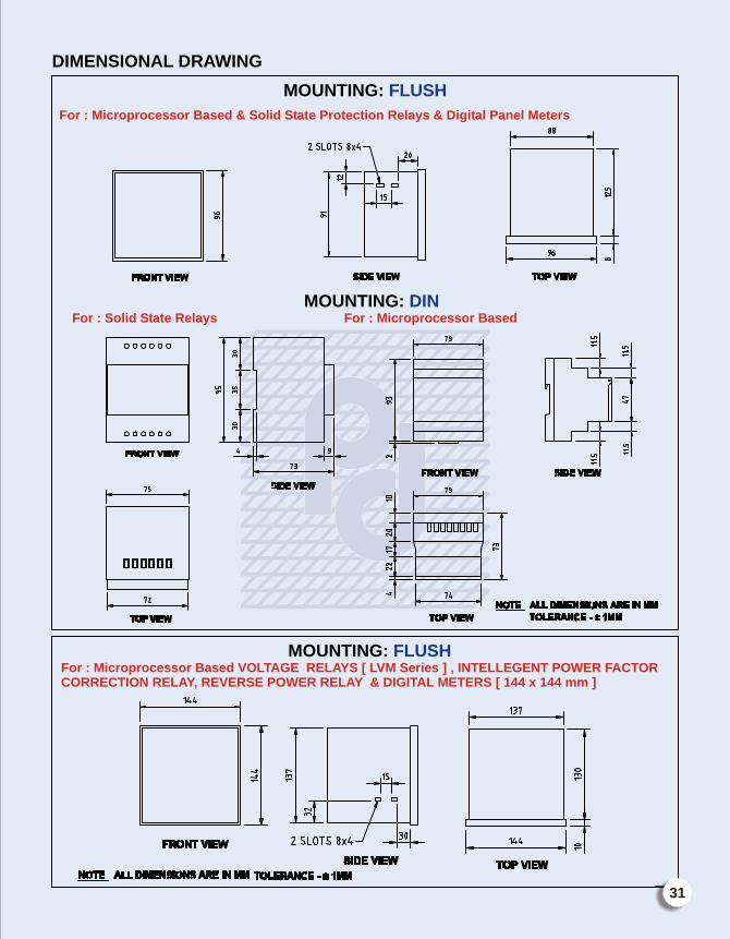
DIMENSIONAL DRAWING
MOUNTING:
FLUSH
For : Microprocessor Based & Solid State Protection Relays & Digital Panel Meters
MOUNTING: DIN For : Solid State Relays For : Microprocessor Based
MOUNTING: FLUSHFor : Microprocessor Based VOLTAGE RELAYS [ LVM Series ] , INTELLEGENT POWER FACTOR CORRECTION RELAY, REVERSE POWER RELAY & DIGITAL METERS [ 144 x 144 mm ]
31
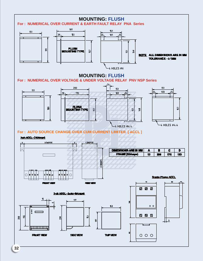
MOUNTING: FLUSH For : NUMERICAL OVER CURRENT & EARTH FAULT RELAY PNA Series
MOUNTING: FLUSH For : NUMERICAL OVER VOLTAGE & UNDER VOLTAGE RELAY PNV NSP Series
For : AUTO SOURCE CHANGE OVER CUM CURRENT LIMITER [ ACCL ]
32
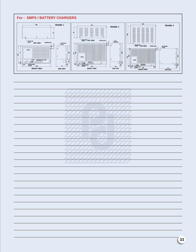
For : SMPS / BATTERY CHARGERS
TOP VIEWTOP VIEW FIXING SLOTFIXING SLOT
M3 HOLESM3 HOLES
3 Nos.3 Nos.
188188
74
74
M3 HOLESM3 HOLES
2 Nos.2 Nos.
44
44
88
88
26
26
88
7474
FRONT VIEWFRONT VIEW
FIXING HOLEFIXING HOLEM3 DIAM3 DIA
114
114
1010
2020
LEDLED TERMINALSTERMINALS LEDLED
188188
FUSEFUSE
SIDE VIEWSIDE VIEW
LOGOLOGO
FRAME- 1FRAME- 1
TOP VIEWTOP VIEW
242242
89
89
M3 HOLESM3 HOLES3 Nos.3 Nos.
M3 HolesM3 Holes2 Nos. 2 Nos.
FIXING SLOTFIXING SLOT
44
44
17
31
73 15
21
52
10
10
1818 FIXING HOLEFIXING HOLEM3 DIAM3 DIA
LOGOLOGO
FRONT VIEWFRONT VIEW
242242
SIDE VIEWSIDE VIEW
8989
88
21
21
15
21
52
TERMINALSTERMINALS
FUSEFUSE
FRAME- 2FRAME- 2
245245
17
41
74
M3 HOLESM3 HOLES3 Nos.3 Nos. FIXING SLOTFIXING SLOT M3 HOLESM3 HOLES
2 Nos.2 Nos.
TOP VIEWTOP VIEW
TERMINALSTERMINALS
FUSEFUSE
FIXING HOLEFIXING HOLEM3 DIAM3 DIA 245245
2020
LOGOLOGO
17
41
74 15
21
52
10
10
2020
174174
22
22
1155
22
FRONT VIEWFRONT VIEW SIDE VIEWSIDE VIEW
FRAME- 3FRAME- 3
33

NotesNotes
34

E-mail: [email protected]
n
n
n
n
n
n
n
n
n
n
n
n
n
n
n
n
n
n
n
n
n
n
n
n
n
n
n
n
n
n
n
n
n
n
n
LARSEN AND TOUBRO LTD
SIEMENS LTD
GE POWER CONTROLS LTD
ABB LTD
CONTROLS & SWITCHGEARS COMPANY LTD
SCHNIEDER ELECTRIC COMPANY
RELIANCE GROUP OF COMPANIES
INFOSYS
WIPRO LTD
ITPL
IBM COMPUTERS
INTEL COMPUTERS
ITC GROUP OF COMPANIES
DEPARTMENT OF SPACE
ONGC
TNEB
JVVN
WESTERN COAL FIELDS LTD
SINGARENI COLLIERIES LTD
HINDUSTAN ZINC LTD
SOUTH EASTERN COAL FIELDS
HUTTI GOLD MINES LTD
I.O.C.L
O.I.L
POWERICA LTD
TYCO ELECTRONICS LTD
MANTRI GROUP
SJR GROUP
H.M.CONSTRUCTIONS
ALPINE HOUSING PVT LTD
PRESTIGE DEVELOPERS
CONCORDE DEVELOPERS
VASWANI BUILDERS AND DEVELOPERS
SOBHA DEVELOPERS
OCEANUS DWELLINGS LTD
SOME IMPORTANT
CLIENT LIST
35
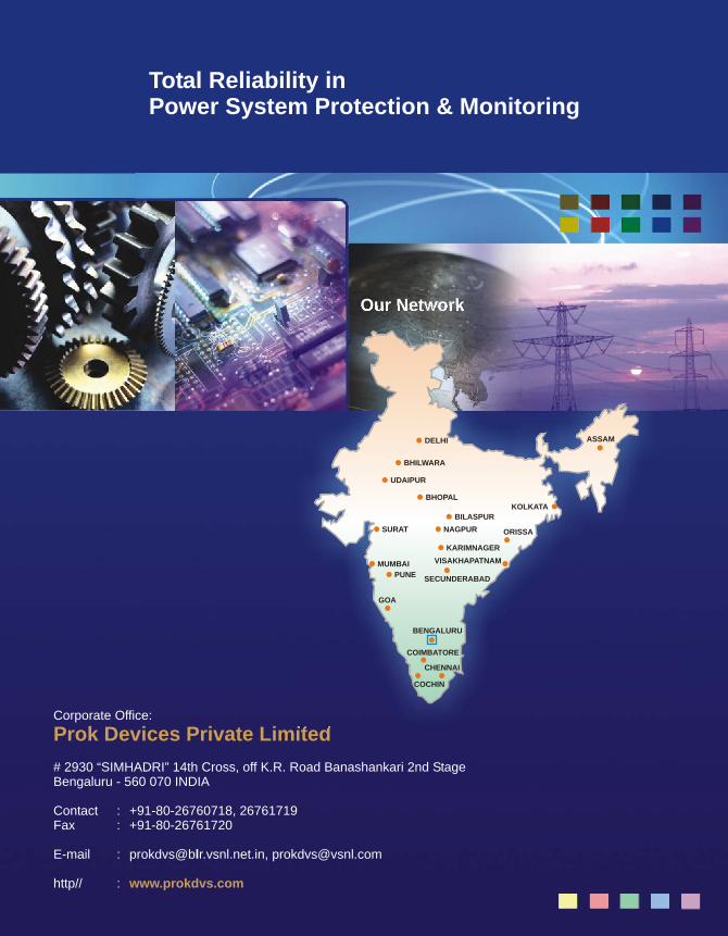
Corporate Office:
# 2930 “SIMHADRI” 14th Cross, off K.R. Road Banashankari 2nd StageBengaluru - 560 070 INDIA
Contact : +91-80-26760718, 26761719Fax : +91-80-26761720
E-mail : [email protected], [email protected]
http// :
Prok Devices Private Limited
www.prokdvs.com
Total Reliability inPower System Protection & Monitoring
Our Network
DELHI ASSAM
BHILWARA
UDAIPUR
BHOPALKOLKATA
BILASPUR
SURAT NAGPUR ORISSA
KARIMNAGER
VISAKHAPATNAM
SECUNDERABAD
MUMBAI
PUNE
GOA
COIMBATORE
CHENNAI
COCHIN
BENGALURU