Embed Size (px)
Citation preview
Catalogue for measuring professionals
Proven and innovativemeasuring technology for compressed airand gases
2018Flow
Dew point
Chart recorder
Pressure
Leakage
Current
Compressed air quality
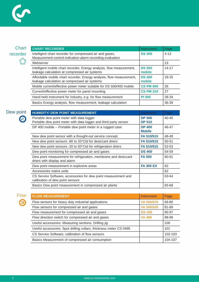
CHART RECORDER Instrument PageIntelligent chart recorder for compressed air and gases, Measurement-control-indication-alarm-recording-evaluation
DS 500 4-13
Webserver 13Intelligent mobile chart recorder, Energy analysis, flow measurement, leakage calculation at compressed air systems
DS 500 mobile
14-17
Affordable mobile chart recorder, Energy analysis, flow measurement, leakage calculation at compressed air systems
DS 400 mobile
18-25
Mobile current/effective power meter suitable for DS 500/400 mobile CS PM 600 26Current/effective power meter for panel mounting CS PM 210 27
Hand-held instrument for industry, e.g. for flow measurement PI 500 28-34
Basics Energy analysis, flow measurement, leakage calculation 36-39
HUMIDITY/ DEW POINT MEASUREMENT Instrument PagePortable dew point meter with data loggerPortable dew point meter with data logger and third party sensor
DP 500DP 510
40-45
DP 400 mobile – Portable dew point meter in a rugged case DP 400 Mobile
46-47
New dew point sensor with a thought-out service concept FA 510/515 48-49New dew point sensors -80 to 20°Ctd for desiccant driers FA 510/515 50-51New dew point sensors -20 to 50°Ctd for refrigeration driers FA 510/515 52-53Dew point monitoring for compressed air and gases DS 400 54-59Dew point measurement for refrigeration, membrane and desiccant driers with display and alarm
FA 500 60-61
Dew point measurement in explosive areas FA 300 EX 62Accessories mains units 62CS Service Software, accessories for dew point measurement and calibration of dew point sensors
63-64
Basics Dew point measurement in compressed air plants 65-68
FLOW MEASUREMENT Instrument Page
Flow sensors for heavy duty industrial applications VA 550/570 69-80Flow sensors for compressed air and gases VA 500/520 81-89Flow measurement for compressed air and gases DS 400 90-97Flow direction switch for compressed air and gases VA 409 98-99
Useful accessories: Measuring sections, Drilling jig 100
Useful accessories: Spot drilling collars, thickness meter CS 0495 101
CS Service Software, calibration of flow sensors 102-103
Basics Measurement of compressed air consumption 104-107
Flow
Chart recorder
Dew point
2 www.cs-instruments.com
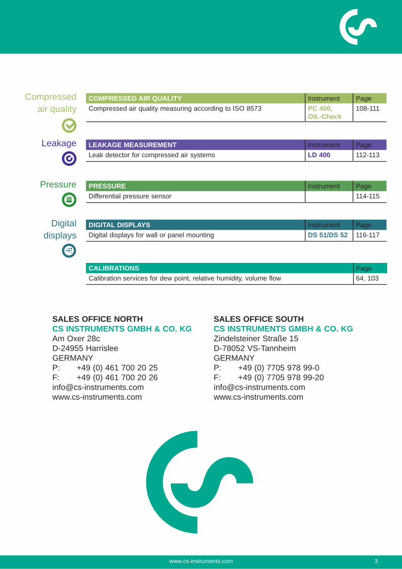
COMPRESSED AIR QUALITY Instrument PageCompressed air quality measuring according to ISO 8573 PC 400,
OIL-Check108-111
LEAKAGE MEASUREMENT Instrument PageLeak detector for compressed air systems LD 400 112-113
DIGITAL DISPLAYS Instrument PageDigital displays for wall or panel mounting DS 51/DS 52 116-117
CALIBRATIONS PageCalibration services for dew point, relative humidity, volume flow 64, 103
Compressed air quality
Leakage
Digital displays
PRESSURE Instrument PageDifferential pressure sensor 114-115
Pressure
SALES OFFICE NORTHCS INSTRUMENTS GMBH & CO. KGAm Oxer 28cD-24955 HarrisleeGERMANYP: +49 (0) 461 700 20 25F: +49 (0) 461 700 20 [email protected]
SALES OFFICE SOUTHCS INSTRUMENTS GMBH & CO. KGZindelsteiner Straße 15D-78052 VS-TannheimGERMANYP: +49 (0) 7705 978 99-0F: +49 (0) 7705 978 [email protected]
www.cs-instruments.com 3
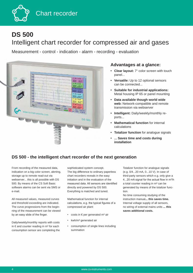
DS 500Intelligent chart recorder for compressed air and gasesMeasurement - control - indication - alarm - recording - evaluation
Advantages at a glance:Clear layout: 7“ color screen with touch panel...
Versatile: Up to 12 optional sensors can be connected...
Suitable for industrial applications: Metal housing IP 65 or panel mounting
Data available though world wide web: Network-compatible and remote transmission via webserver
Intelligent: Daily/weekly/monthly re-ports...
Mathematical function for internal calculations
Totalizer function for analogue signals
... Saves time and costs during installation
DS 500 - the intelligent chart recorder of the next generation
From recording of the measured data, indication on a big color screen, alerting, storage up to remote read-out via webserver... this is all possible with DS 500. By means of the CS Soft Basic software alarms can be sent via SMS or e-mail.
All measured values, measured curves and threshold exceeding are indicated. The curve progressions from the begin-ning of the measurement can be viewed
Daily/weekly/monthly reports with costs in € and counter reading in m³ for each consumption sensor are completing the
sophisticated system concept.The big difference to ordinary paperless chart recorders reveals in the easy initiation and in the evaluation of the
directly and powered by DS 500. Everything is matched and tuned.
Mathematical function for internal
compressed air plant:
costs in € per generated m³ air
kwh/m³ generated air
consumption of single lines including summation
Totalizer function for analogue signals (e.g. 0/4...20 mA, 0...10 V). In case of third-party sensors which e.g. only give a
a total counter reading in m³ can be generated by means of the totalizer func-tion.No time consuming studying of the instruction manual... this saves time. Internal voltage supply of all sensors, no wiring of external mains units ... this saves additional costs.
www.cs-instruments.com4
Chart recorder
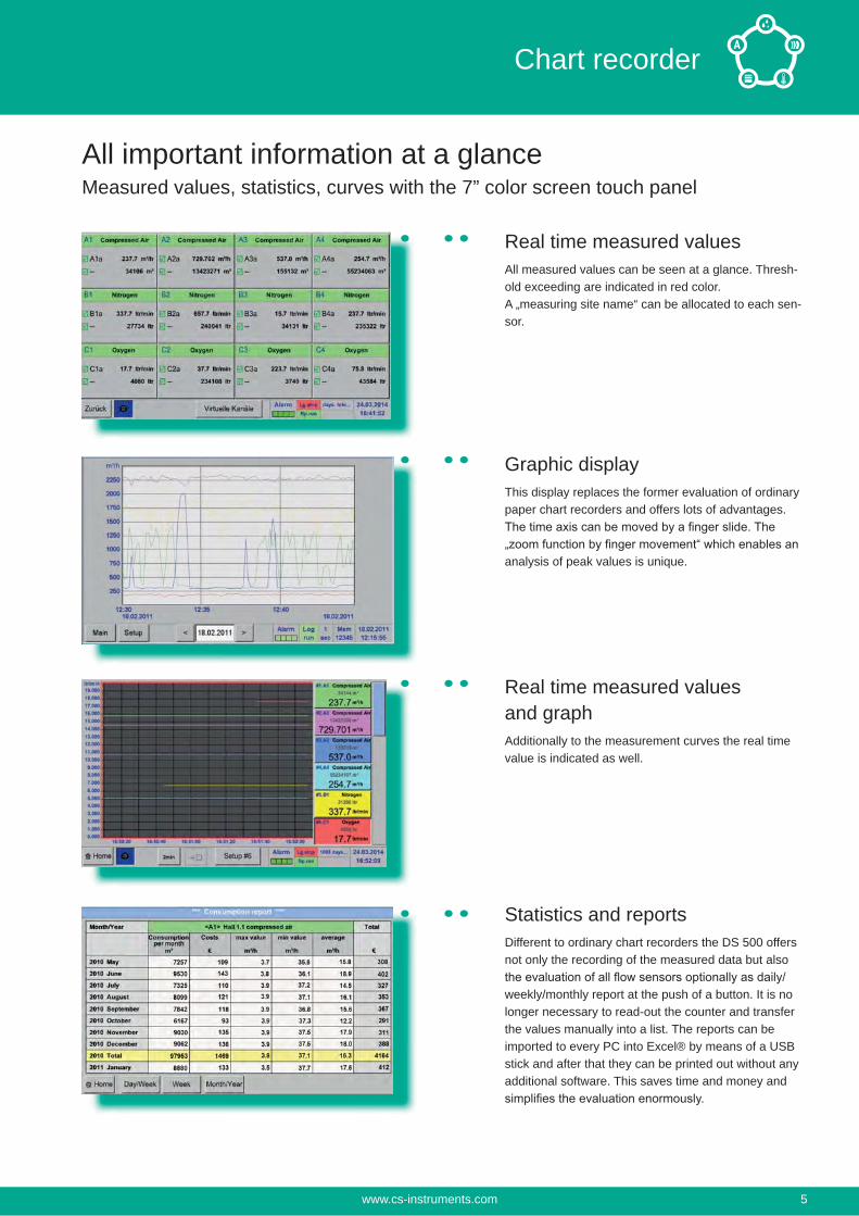
All important information at a glanceMeasured values, statistics, curves with the 7” color screen touch panel
Real time measured valuesAll measured values can be seen at a glance. Thresh-old exceeding are indicated in red color.A „measuring site name“ can be allocated to each sen-sor.
Graphic displayThis display replaces the former evaluation of ordinary paper chart recorders and offers lots of advantages.
analysis of peak values is unique.
Real time measured values and graphAdditionally to the measurement curves the real time value is indicated as well.
Statistics and reportsDifferent to ordinary chart recorders the DS 500 offers not only the recording of the measured data but also
weekly/monthly report at the push of a button. It is no longer necessary to read-out the counter and transfer the values manually into a list. The reports can be imported to every PC into Excel® by means of a USB stick and after that they can be printed out without any additional software. This saves time and money and
www.cs-instruments.com 5
Chart recorder
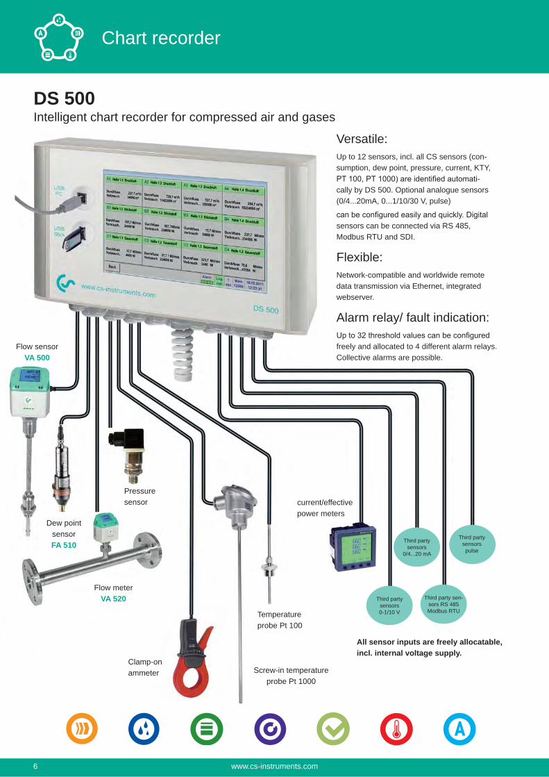
DS 500Intelligent chart recorder for compressed air and gases
Versatile:Up to 12 sensors, incl. all CS sensors (con-sumption, dew point, pressure, current, KTY,
-cally by DS 500. Optional analogue sensors (0/4...20mA, 0...1/10/30 V, pulse)
sensors can be connected via RS 485, Modbus RTU and SDI.
Flexible:Network-compatible and worldwide remote data transmission via Ethernet, integrated webserver.
Alarm relay/ fault indication:
freely and allocated to 4 different alarm relays. Collective alarms are possible.
Flow sensorVA 500
Clamp-on ammeter Screw-in temperature
probe Pt 1000
Temperatureprobe Pt 100
current/effectivepower meters
All sensor inputs are freely allocatable, incl. internal voltage supply.
Third party sensors
0/4...20 mA
Third party sensors0-1/10 V
Third party sen-sors RS 485Modbus RTU
Third party sensorspulse
Dew pointsensorFA 510
Flow meterVA 520
Pressuresensor
www.cs-instruments.com6
Chart recorder
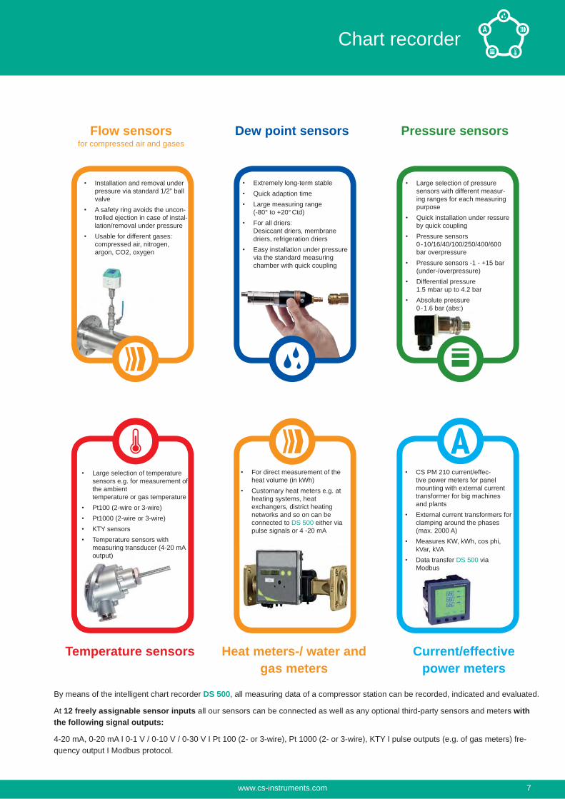
Installation and removal under pressure via standard 1/2” ball valveA safety ring avoids the uncon-trolled ejection in case of instal-lation/removal under pressureUsable for different gases: compressed air, nitrogen, argon, CO2, oxygen
Extremely long-term stableQuick adaption timeLarge measuring range (-80° to +20° Ctd)For all driers: Desiccant driers, membrane driers, refrigeration driersEasy installation under pressure via the standard measuring chamber with quick coupling
Large selection of pressure sensors with different measur-ing ranges for each measuring purposeQuick installation under ressure by quick couplingPressure sensors 0-10/16/40/100/250/400/600 bar overpressurePressure sensors -1 - +15 bar (under-/overpressure)Differential pressure 1.5 mbar up to 4.2 barAbsolute pressure 0-1.6 bar (abs:)
CS PM 210 current/effec-tive power meters for panel mounting with external current transformer for big machines and plantsExternal current transformers for clamping around the phases (max. 2000 A)Measures KW, kWh, cos phi, kVar, kVAData transfer DS 500 via Modbus
For direct measurement of the heat volume (in kWh)Customary heat meters e.g. at heating systems, heat exchangers, district heating networks and so on can be connected to DS 500 either via pulse signals or 4 -20 mA
Large selection of temperature sensors e.g. for measurement of the ambient temperature or gas temperaturePt100 (2-wire or 3-wire)Pt1000 (2-wire or 3-wire)KTY sensorsTemperature sensors with measuring transducer (4-20 mA output)
Flow sensorsfor compressed air and gases
Dew point sensors Pressure sensors
Temperature sensors Heat meters-/ water and gas meters
Current/effective power meters
By means of the intelligent chart recorder DS 500, all measuring data of a compressor station can be recorded, indicated and evaluated.
At 12 freely assignable sensor inputs all our sensors can be connected as well as any optional third-party sensors and meters with the following signal outputs:
4-20 mA, 0-20 mA I 0-1 V / 0-10 V / 0-30 V I Pt 100 (2- or 3-wire), Pt 1000 (2- or 3-wire), KTY I pulse outputs (e.g. of gas meters) fre-quency output I Modbus protocol.
www.cs-instruments.com 7
Chart recorder

Descripation Order No.DS 500 - intelligent chart recorder in basic version (4 sensor inputs) 0500 5000
Option 4 additional sensor inputs for DS 500 Z500 5001
Option 8 additional sensor inputs for DS 500 Z500 5002
Option Integrated webserver Z500 5003
Z500 5004
Option version for panel mounting Z500 5006
Option power supply 24 VDC (instead of 100...240 VAC) Z500 5007
Option „mathematics calculation function“ for 4 freely selectable „virtual“ chan-nels, (mathematical functions: addition, subtraction, division, multiplication)
Z500 5008
Option „Totalizer function for analogue signals“ Z500 5009
Z500 3008
CS Soft Basic - data evaluation in graphic and table form, reading out of the measured data via USB or Ethernet
0554 7040
CS Soft Network - Database Client/Server Solution (up to 5 DS 500) - database (MySQL) to Server - data evaluation via Client-Software
0554 7041
CS Soft Network - Database Client/Server Solution (up to 10 DS 500) - database (MySQL) to Server - data evaluation via Client-Software
0554 7042
CS Soft Network - Database Client/Server Solution (up to 20 DS 500) - database (MySQL) to Server - data evaluation via Client-Software
0554 7043
CS Soft Network - Database Client/Server Solution (> 20 DS 500) - database (MySQL) to Server - data evaluation via Client-Software
0554 7044
Technical data DS 500Dimensions of housing: 280 x 170 x 90 mm, IP 65
Connections: 18 x PG 12 for sensors and supply, alarm relays 1 x RJ 45 Ethernet connection
Version panel mounting: Cutout panel 250 x 156 mm
Weight: 7.3 Kg
Material: Die cast metal, front screen polyester
Sensor inputs: 4/8/12 sensor inputs for analogue and digital sensors freely allocatable. See options Digital CS sensors for dew point and consumption with SDI interface FA/VA series, digital third-party sen-sors RS 485 / Modbus RTU, other bus systems realizable on request.Analogue CS Sensors for pressure, temperature, clamp-on ammeters pre-configured.Analogue third-party sensors 0/4...20 mA, 0...1/10/30V, pulse, Pt 100 / Pt 1000, KTY
Power supply for sensors:
24 VDC, max. 130 mA per sensor, integrated mains unit max. 24 VDC, 25 W. In case of version 8/12 sensor inputs, 2 integrated mains units each max. 24 VDC, 25 W.
Interfaces: USB stick, USB cable, Ethernet / RS 485 Modbus RTU / TCP, SDI other bus systems on request, WEB server optionally
Outputs: 4 relays (changeover contact 230 VAC, 6 A), alarm management, relays freely programmable, collective alarmAnalogue otuput, pulse in case of sensors with own signal output looped, like e.g. VA/FA series
Memory card: Memory size 4 GB SD memory card standard
Power supply: 100...240 VAC / 50-60 Hz, special version 24 VDC
Color screen: 7“ touch panel TFT transmissive, graphics, curves, statistics
Accuracy:Operating temperature: 0...50°C
Storage temperature: -20...70°C
Optionally: Webserver
Optionally: Quick measurement with 10 ms sampling rate for analogue sensors, Max/Min indication per second
Optionally:
Input signalsCurrent signalinternal or exter-nal power supplyMeasuring rangeResolutionAccuracyInput resistance
(0...20mA/ 4...20mA)
0...20 mA0.0001 mA± 0.03 mA ± 0.05 %
Voltage signalMeasuring rangeResolutionAccuracyInput resistance
(0...1 V)0...1 V0.05 mV± 0.2 mV ± 0.05 %
Voltage signalMeasuring rangeResolutionAccuracyInput resistance
(0...10 V / 30 V)0...10 V0.5 mV± 2 mV ± 0.05 %
RTD Pt 100Measuring rangeResolutionAccurancy
-200...850°C0.1°C± 0.2°C (-100...400°C)± 0.3°C (further range)
RTD Pt 1000Measuring rangeResolutionAccuracy
-200...850°C0.1°C± 0.2° (-100...400°C)
PulseMeasuring range
min pulse length 100 μs frequency 0...1 kHzmax. 30 VDC
www.cs-instruments.com8
Chart recorder
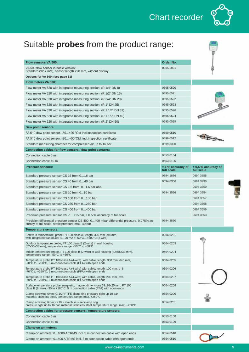
Suitable probes from the product range:
Flow sensors VA 500: Order No.
Standard (92.7 m/s), sensor length 220 mm, without display0695 5001
Options for VA 500: (see page 81)
Pressure sensors: ± 1 % accuracy of full scale
± 0,5 % accuracy of full scale
Standard pressure sensor CS 16 from 0…16 bar 0694 1886 0694 3555
Standard pressure sensor CS 40 from 0…40 bar 0694 0356 0694 3930
Standard pressure sensor CS 1.6 from 0...1.6 bar abs. 0694 3550
Standard pressure sensor CS 10 from 0...10 bar 0694 3556 0694 3554
Standard pressure sensor CS 100 from 0…100 bar 0694 3557
Standard pressure sensor CS 250 from 0…250 bar 0694 3558
Standard pressure sensor CS 400 from 0…400 bar 0694 3559
Precision pressure sensor CS -1...+15 bar, ± 0.5 % accuracy of full scale 0694 3553
Precision differential pressure sensor CS 400, 0...400 mbar differential pressure, 0.075% ac-curacy of full scale, static pressure max. 40 bar
0694 3560
Flow meters VA 520:
Flow meter VA 520 with integrated measuring section, (R 1/4“ DN 8) 0695 0520
Flow meter VA 520 with integrated measuring section, (R 1/2“ DN 15) 0695 0521
Flow meter VA 520 with integrated measuring section, (R 3/4“ DN 20) 0695 0522
Flow meter VA 520 with integrated measuring section, (R 1“ DN 25) 0695 0523
Flow meter VA 520 with integrated measuring section, (R 1 1/4“ DN 32) 0695 0526
Flow meter VA 520 with integrated measuring section, (R 1 1/2“ DN 40) 0695 0524
Flow meter VA 520 with integrated measuring section, (R 2“ DN 50) 0695 0525
Dew point sensors:
0699 0510
0699 0512
Standard measuring chamber for compressed air up to 16 bar 0699 3390
Connection cable 5 m 0553 0104
Connection cable 10 m 0553 0105
Temperature sensors:
Screw-in temperature probe PT 100 class A, length: 300 mm, d=6mm,with integrated transducer 4…20 mA = -50°C…+500°C (2-wire)
0604 0201
Outdoor temperature probe, PT 100 class B (2-wire) in wall housing(82x55x33 mm), temperature range: -50°C to +80°C
0604 0203
Indoor temperature probe, PT 100 class B (2-wire) in wall housing (82x55x33 mm),temperature range: -50°C to +80°C
0604 0204
Temperature probe PT 100 class A (4-wire) with cable, length: 300 mm, d=6 mm,-70°C to +260°C, 5 m connection cable (PFA) with open ends
0604 0205
Temperature probe PT 100 class A (4-wire) with cable, length: 100 mm, d=6-70°C to +260°C, 5 m connection cable (PFA) with open ends
0604 0206
Temperature probe PT 100 class A (4-wire) with cable, length: 200 mm, d=6-70°C to +260°C, 5 m connection cable (PFA) with open ends
0604 0207
Surface temperature probe, magnetic, magnet dimensions 39x26x25 mm, PT 100class B (2-wire), -30 to +180°C, 5 m connection cable (PFA) with open ends
0604 0208
Clamp screwing 6mm; G 1/2“ PTFE clamp ring pressure tight up 10 barmaterial: stainless steel, temperature range: max. +260°C
0554 0200
Clamp screwing 6mm; G 1/2» stainless steel clamp ringpressure tight up to 16 bar, material: stainless steel, temperature range: max. +260°C
0554 0201
Connection cables for pressure sensors / temperature sensors:
Connection cable 5 m 0553 0108
Connection cable 10 m 0553 0109
Clamp-on ammeters:
Clamp-on ammeter 0...1000 A TRMS incl. 5 m connection cable with open ends 0554 0518
Clamp-on ammeter 0...400 A TRMS incl. 3 m connection cable with open ends 0554 0510
www.cs-instruments.com 9
Chart recorder
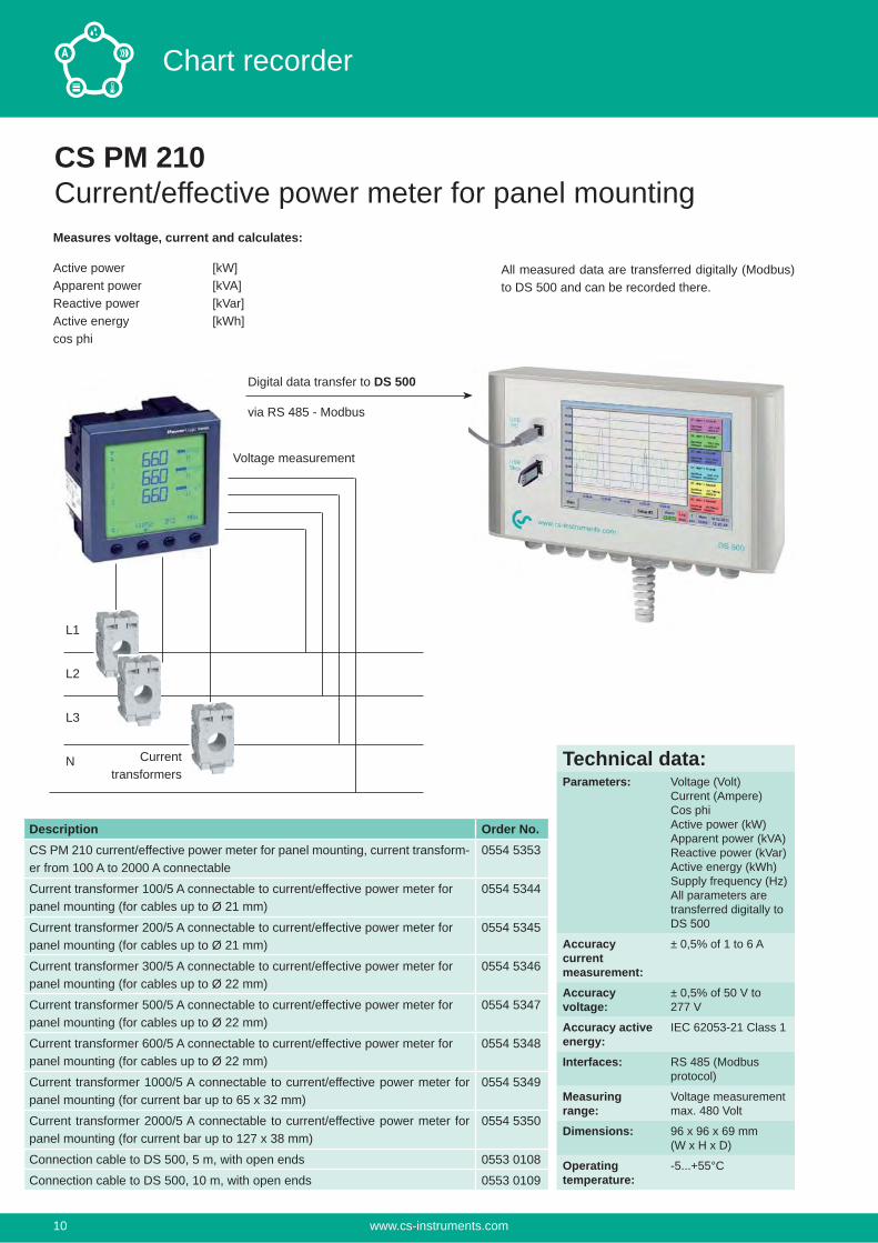
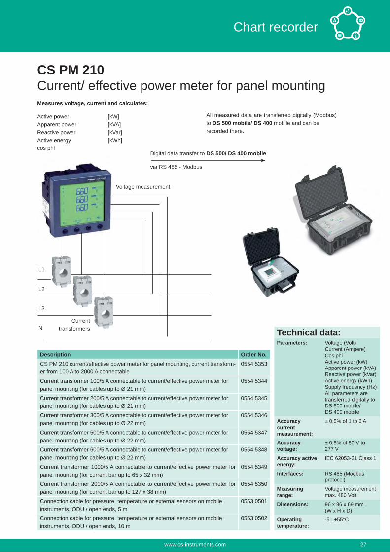
CS PM 210Current/effective power meter for panel mountingMeasures voltage, current and calculates:
Active power [kW]Apparent power [kVA]Reactive power [kVar]Active energy [kWh]cos phi
All measured data are transferred digitally (Modbus) to DS 500 and can be recorded there.
Voltage measurement
L1
L2
L3
N Currenttransformers
Digital data transfer to DS 500
via RS 485 - Modbus
Description Order No.CS PM 210 current/effective power meter for panel mounting, current transform-er from 100 A to 2000 A connectable
0554 5353
Current transformer 100/5 A connectable to current/effective power meter for panel mounting (for cables up to Ø 21 mm)
0554 5344
Current transformer 200/5 A connectable to current/effective power meter for panel mounting (for cables up to Ø 21 mm)
0554 5345
Current transformer 300/5 A connectable to current/effective power meter for panel mounting (for cables up to Ø 22 mm)
0554 5346
Current transformer 500/5 A connectable to current/effective power meter for panel mounting (for cables up to Ø 22 mm)
0554 5347
Current transformer 600/5 A connectable to current/effective power meter for panel mounting (for cables up to Ø 22 mm)
0554 5348
Current transformer 1000/5 A connectable to current/effective power meter for panel mounting (for current bar up to 65 x 32 mm)
0554 5349
Current transformer 2000/5 A connectable to current/effective power meter for panel mounting (for current bar up to 127 x 38 mm)
0554 5350
Connection cable to DS 500, 5 m, with open ends 0553 0108
Connection cable to DS 500, 10 m, with open ends 0553 0109
Technical data:Parameters: Voltage (Volt)
Current (Ampere)Cos phiActive power (kW)Apparent power (kVA)Reactive power (kVar)Active energy (kWh)Supply frequency (Hz)All parameters aretransferred digitally to DS 500
Accuracycurrentmeasurement:
± 0,5% of 1 to 6 A
Accuracyvoltage:
± 0,5% of 50 V to 277 V
Accuracy active energy:
IEC 62053-21 Class 1
Interfaces: RS 485 (Modbus protocol)
Measuring range:
Voltage measurement max. 480 Volt
Dimensions: 96 x 96 x 69 mm(W x H x D)
Operatingtemperature:
-5...+55°C
www.cs-instruments.com10
Chart recorder
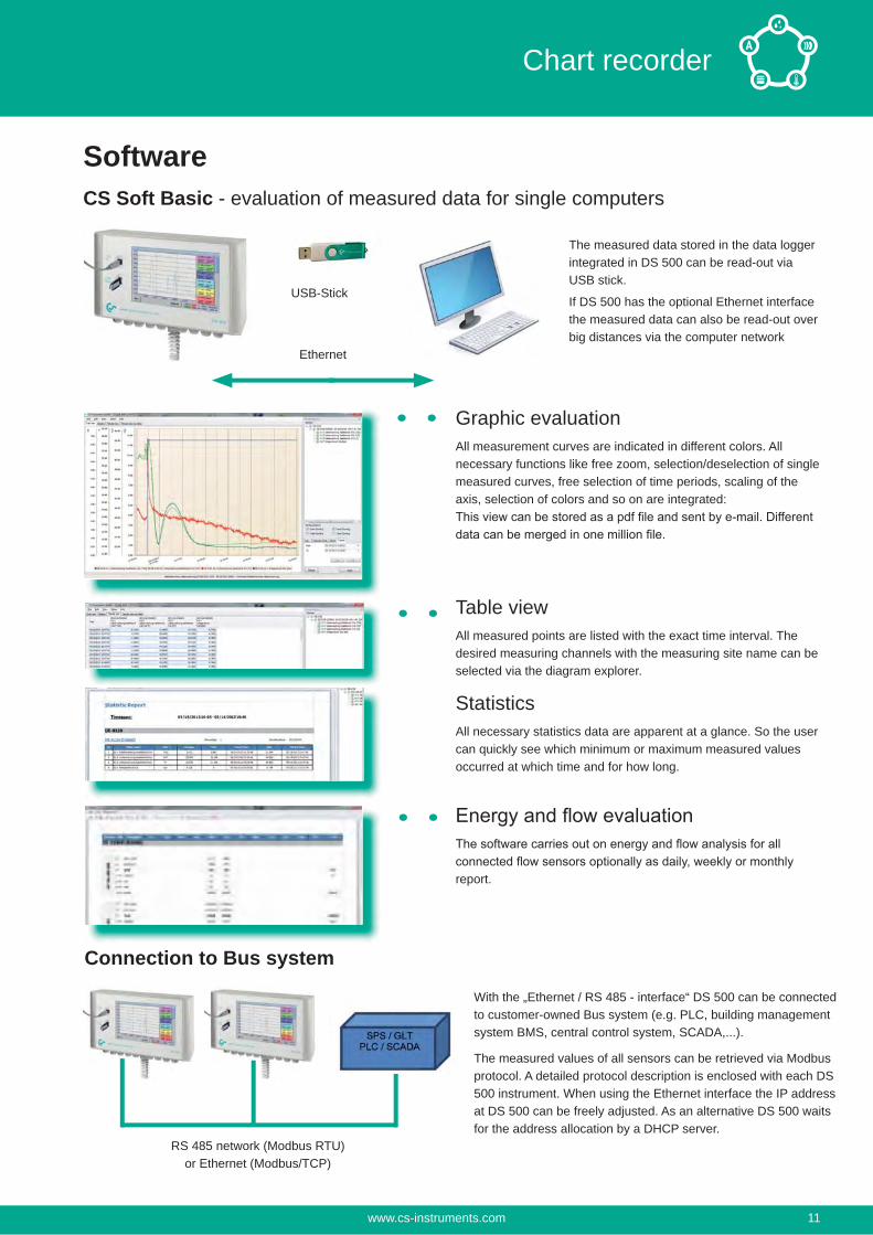
CS Soft Basic - evaluation of measured data for single computers
Graphic evaluationAll measurement curves are indicated in different colors. All necessary functions like free zoom, selection/deselection of single measured curves, free selection of time periods, scaling of the axis, selection of colors and so on are integrated:
Table viewAll measured points are listed with the exact time interval. The desired measuring channels with the measuring site name can be selected via the diagram explorer.
StatisticsAll necessary statistics data are apparent at a glance. So the user can quickly see which minimum or maximum measured values occurred at which time and for how long.
report.
Ethernet
USB-Stick
The measured data stored in the data logger integrated in DS 500 can be read-out via USB stick.
If DS 500 has the optional Ethernet interface the measured data can also be read-out over big distances via the computer network
With the „Ethernet / RS 485 - interface“ DS 500 can be connected to customer-owned Bus system (e.g. PLC, building management system BMS, central control system, SCADA,...).
The measured values of all sensors can be retrieved via Modbus protocol. A detailed protocol description is enclosed with each DS 500 instrument. When using the Ethernet interface the IP address at DS 500 can be freely adjusted. As an alternative DS 500 waits for the address allocation by a DHCP server.
RS 485 network (Modbus RTU)or Ethernet (Modbus/TCP)
Software
Connection to Bus system
www.cs-instruments.com 11
Chart recorder
Load background image
measurement valuesRed measurement values in case of alarm exceeding
Selection of the measuring channels to be indicatedEasy zoom in and zoom outUp to 8 y-axisQuick access to day, week, month view
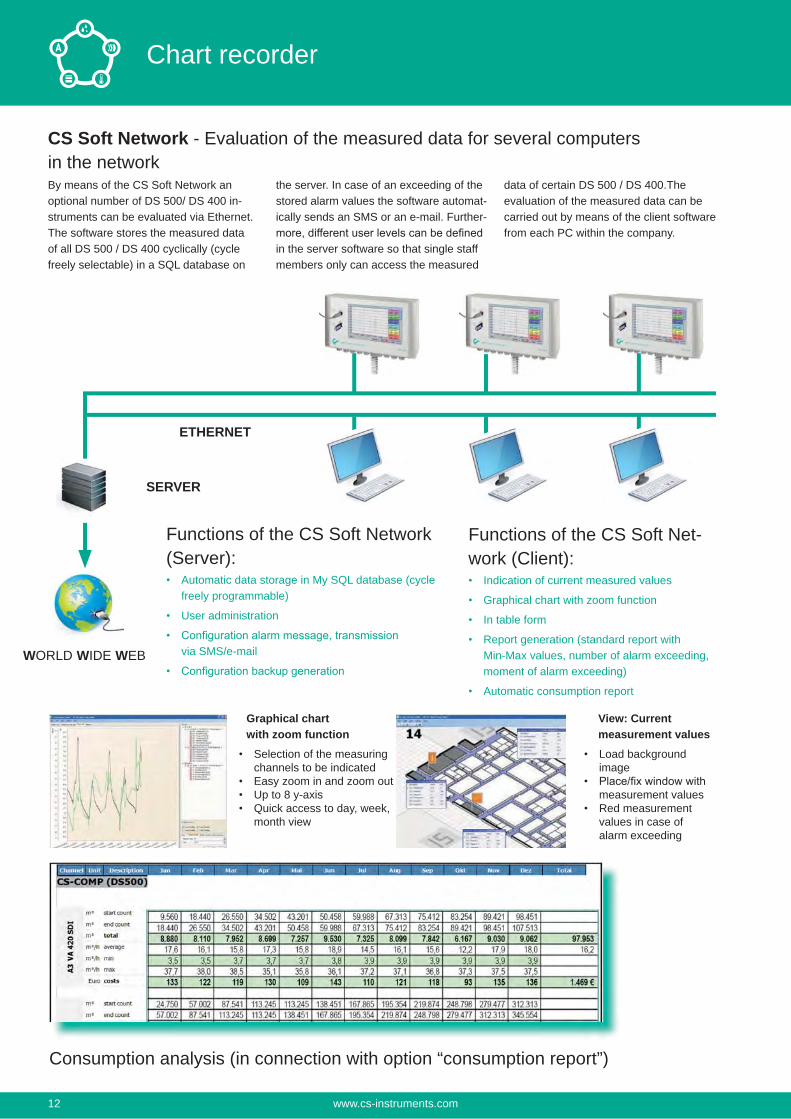
Consumption analysis (in connection with option “consumption report”)
CS Soft Network - Evaluation of the measured data for several computers in the networkBy means of the CS Soft Network an optional number of DS 500/ DS 400 in-struments can be evaluated via Ethernet. The software stores the measured data of all DS 500 / DS 400 cyclically (cycle freely selectable) in a SQL database on
the server. In case of an exceeding of the stored alarm values the software automat-ically sends an SMS or an e-mail. Further-
in the server software so that single staff members only can access the measured
data of certain DS 500 / DS 400.The evaluation of the measured data can be carried out by means of the client software from each PC within the company.
SERVER
ETHERNET
WORLD WIDE WEB
Functions of the CS Soft Network (Server):
Automatic data storage in My SQL database (cycle freely programmable)
User administration
via SMS/e-mail
Functions of the CS Soft Net-work (Client):
Indication of current measured values
Graphical chart with zoom function
In table form
Report generation (standard report with Min-Max values, number of alarm exceeding, moment of alarm exceeding)
Automatic consumption report
Graphical chartwith zoom function
View: Current measurement values
www.cs-instruments.com12
Chart recorder
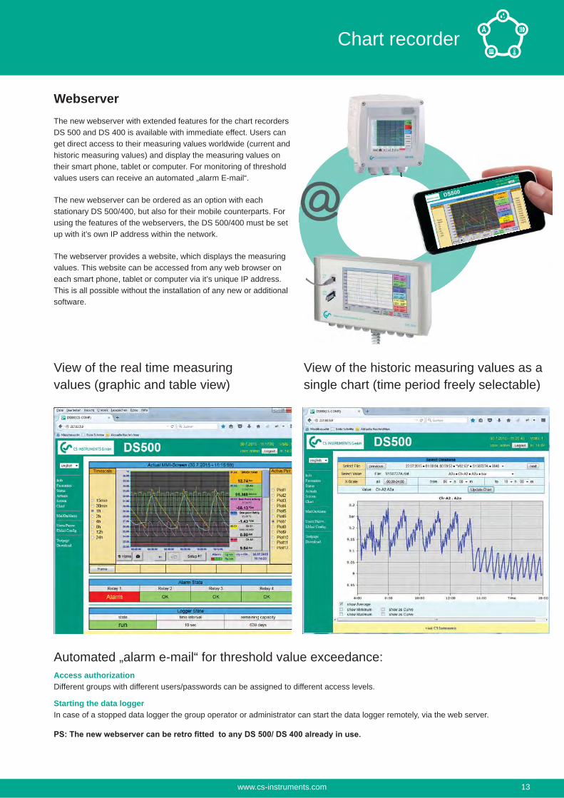
WebserverThe new webserver with extended features for the chart recorders DS 500 and DS 400 is available with immediate effect. Users can get direct access to their measuring values worldwide (current and historic measuring values) and display the measuring values on their smart phone, tablet or computer. For monitoring of threshold values users can receive an automated „alarm E-mail“.
The new webserver can be ordered as an option with each stationary DS 500/400, but also for their mobile counterparts. For using the features of the webservers, the DS 500/400 must be set up with it’s own IP address within the network.
The webserver provides a website, which displays the measuring values. This website can be accessed from any web browser on each smart phone, tablet or computer via it’s unique IP address. This is all possible without the installation of any new or additional software.
View of the real time measuring values (graphic and table view)
View of the historic measuring values as a single chart (time period freely selectable)
Automated „alarm e-mail“ for threshold value exceedance: Access authorizationDifferent groups with different users/passwords can be assigned to different access levels.
Starting the data loggerIn case of a stopped data logger the group operator or administrator can start the data logger remotely, via the web server.
www.cs-instruments.com 13
Chart recorder
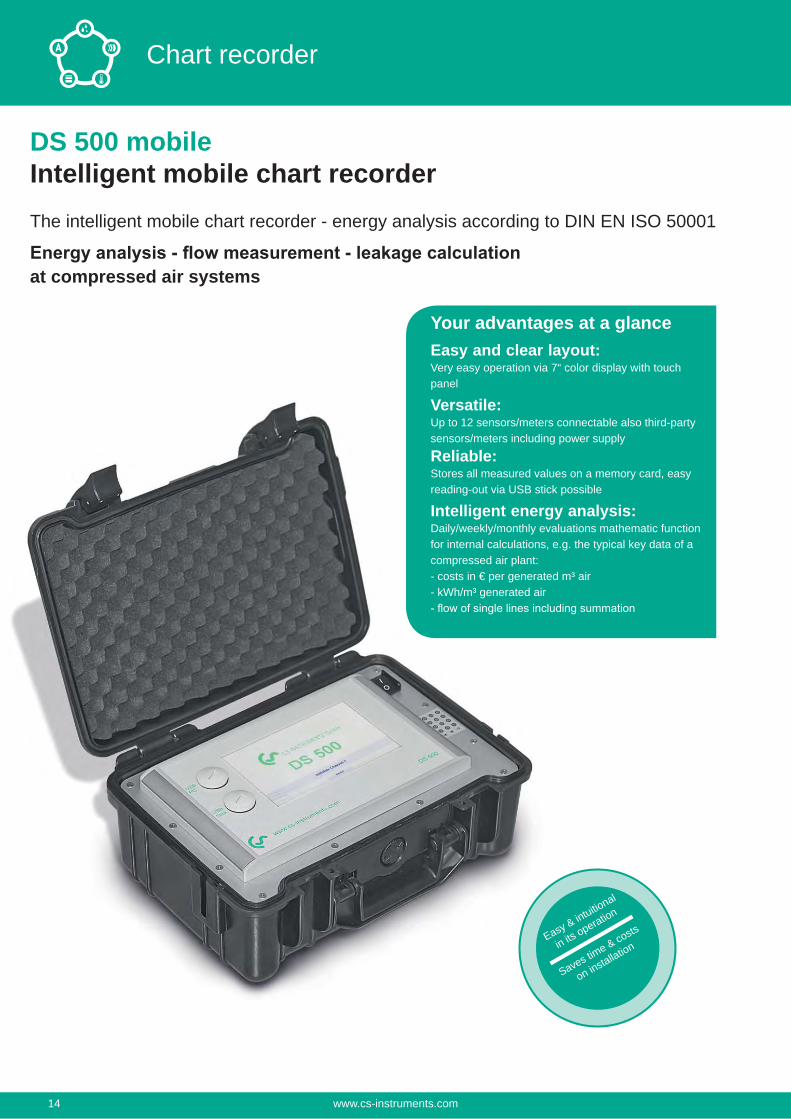
DS 500 mobileIntelligent mobile chart recorderThe intelligent mobile chart recorder - energy analysis according to DIN EN ISO 50001
at compressed air systems
Your advantages at a glanceEasy and clear layout:Very easy operation via 7“ color display with touch panel
Versatile:Up to 12 sensors/meters connectable also third-party sensors/meters including power supply
Reliable: Stores all measured values on a memory card, easy reading-out via USB stick possible
Intelligent energy analysis:Daily/weekly/monthly evaluations mathematic function for internal calculations, e.g. the typical key data of a compressed air plant:- costs in € per generated m³ air- kWh/m³ generated air
Easy & intuitional
in its operation
Saves time & costs
on installation
www.cs-instruments.com14
Chart recorder
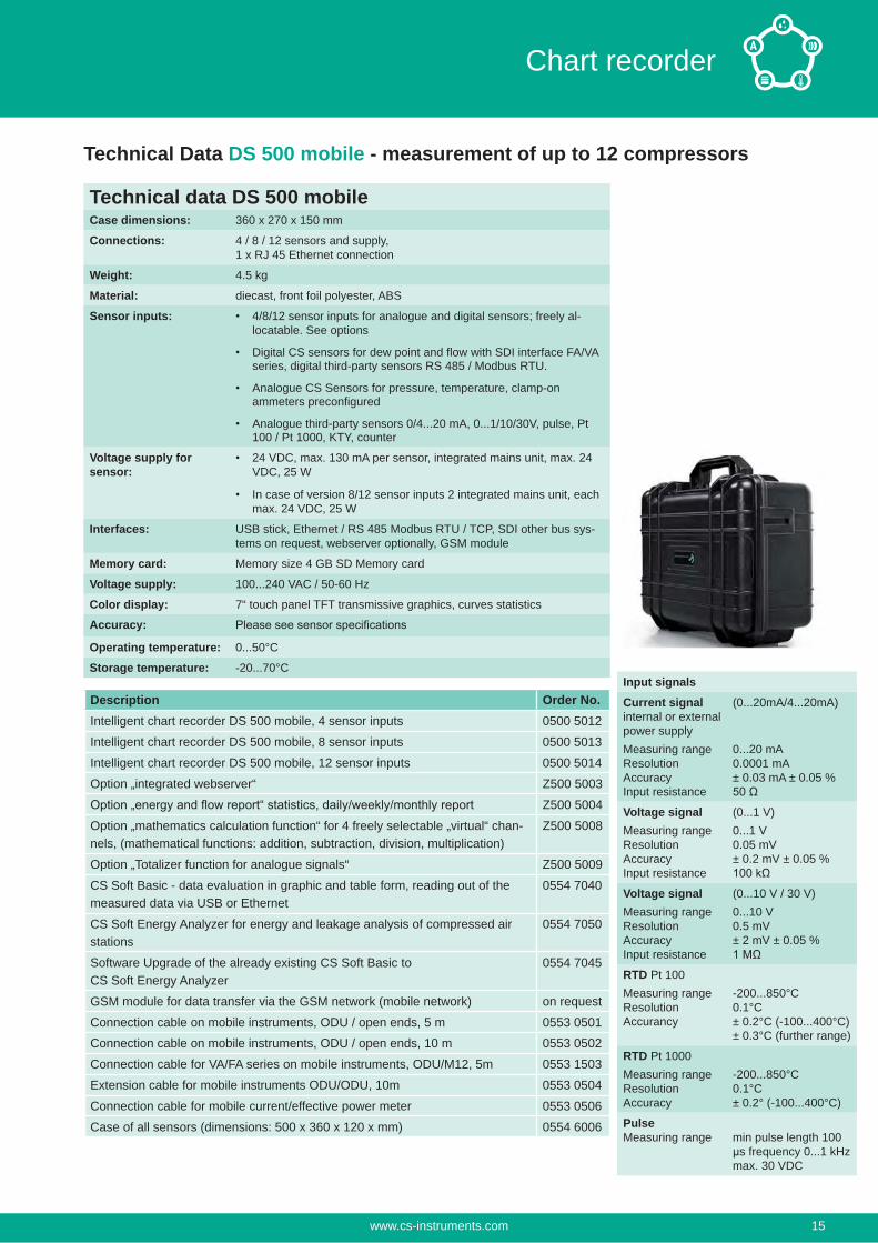
Technical Data DS 500 mobile - measurement of up to 12 compressors
Description Order No.Intelligent chart recorder DS 500 mobile, 4 sensor inputs 0500 5012
Intelligent chart recorder DS 500 mobile, 8 sensor inputs 0500 5013
Intelligent chart recorder DS 500 mobile, 12 sensor inputs 0500 5014
Option „integrated webserver“ Z500 5003
Z500 5004
Option „mathematics calculation function“ for 4 freely selectable „virtual“ chan-nels, (mathematical functions: addition, subtraction, division, multiplication)
Z500 5008
Option „Totalizer function for analogue signals“ Z500 5009
CS Soft Basic - data evaluation in graphic and table form, reading out of the measured data via USB or Ethernet
0554 7040
CS Soft Energy Analyzer for energy and leakage analysis of compressed air stations
0554 7050
Software Upgrade of the already existing CS Soft Basic to CS Soft Energy Analyzer
0554 7045
GSM module for data transfer via the GSM network (mobile network) on request
Connection cable on mobile instruments, ODU / open ends, 5 m 0553 0501
Connection cable on mobile instruments, ODU / open ends, 10 m 0553 0502
Connection cable for VA/FA series on mobile instruments, ODU/M12, 5m 0553 1503
Extension cable for mobile instruments ODU/ODU, 10m 0553 0504
Connection cable for mobile current/effective power meter 0553 0506
Case of all sensors (dimensions: 500 x 360 x 120 x mm) 0554 6006
Technical data DS 500 mobileCase dimensions: 360 x 270 x 150 mm
Connections: 4 / 8 / 12 sensors and supply,1 x RJ 45 Ethernet connection
Weight: 4.5 kg
Material: diecast, front foil polyester, ABS
Sensor inputs: 4/8/12 sensor inputs for analogue and digital sensors; freely al-locatable. See options
Digital CS sensors for dew point and flow with SDI interface FA/VA series, digital third-party sensors RS 485 / Modbus RTU.
Analogue CS Sensors for pressure, temperature, clamp-on ammeters preconfigured
Analogue third-party sensors 0/4...20 mA, 0...1/10/30V, pulse, Pt 100 / Pt 1000, KTY, counter
Voltage supply for sensor:
24 VDC, max. 130 mA per sensor, integrated mains unit, max. 24 VDC, 25 W
In case of version 8/12 sensor inputs 2 integrated mains unit, each max. 24 VDC, 25 W
Interfaces: USB stick, Ethernet / RS 485 Modbus RTU / TCP, SDI other bus sys-tems on request, webserver optionally, GSM module
Memory card: Memory size 4 GB SD Memory card
Voltage supply: 100...240 VAC / 50-60 Hz
Color display: 7“ touch panel TFT transmissive graphics, curves statistics
Accuracy:
Operating temperature: 0...50°C
Storage temperature: -20...70°CInput signalsCurrent signalinternal or external power supplyMeasuring rangeResolutionAccuracyInput resistance
(0...20mA/4...20mA)
0...20 mA0.0001 mA± 0.03 mA ± 0.05 %
Voltage signalMeasuring rangeResolutionAccuracyInput resistance
(0...1 V)0...1 V0.05 mV± 0.2 mV ± 0.05 %
Voltage signalMeasuring rangeResolutionAccuracyInput resistance
(0...10 V / 30 V)0...10 V0.5 mV± 2 mV ± 0.05 %
RTD Pt 100Measuring rangeResolutionAccurancy
-200...850°C0.1°C± 0.2°C (-100...400°C)± 0.3°C (further range)
RTD Pt 1000Measuring rangeResolutionAccuracy
-200...850°C0.1°C± 0.2° (-100...400°C)
PulseMeasuring range min pulse length 100
μs frequency 0...1 kHzmax. 30 VDC
www.cs-instruments.com 15
Chart recorder
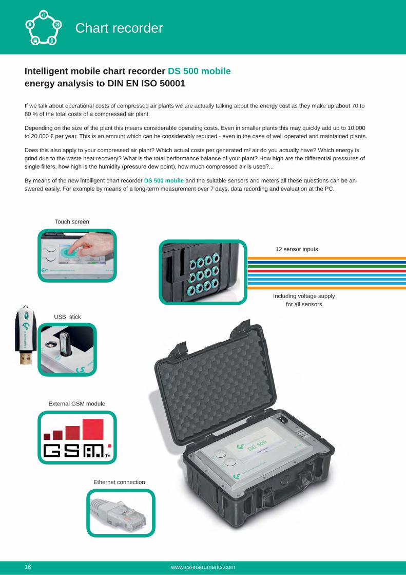
Intelligent mobile chart recorder DS 500 mobileenergy analysis to DIN EN ISO 50001
If we talk about operational costs of compressed air plants we are actually talking about the energy cost as they make up about 70 to 80 % of the total costs of a compressed air plant.
Depending on the size of the plant this means considerable operating costs. Even in smaller plants this may quickly add up to 10.000 to 20.000 € per year. This is an amount which can be considerably reduced - even in the case of well operated and maintained plants.
Does this also apply to your compressed air plant? Which actual costs per generated m³ air do you actually have? Which energy is grind due to the waste heat recovery? What is the total performance balance of your plant? How high are the differential pressures of
By means of the new intelligent chart recorder DS 500 mobile and the suitable sensors and meters all these questions can be an-swered easily. For example by means of a long-term measurement over 7 days, data recording and evaluation at the PC.
Touch screen
USB stick
External GSM module
Ethernet connection
12 sensor inputs
Including voltage supplyfor all sensors
www.cs-instruments.com16
Chart recorder
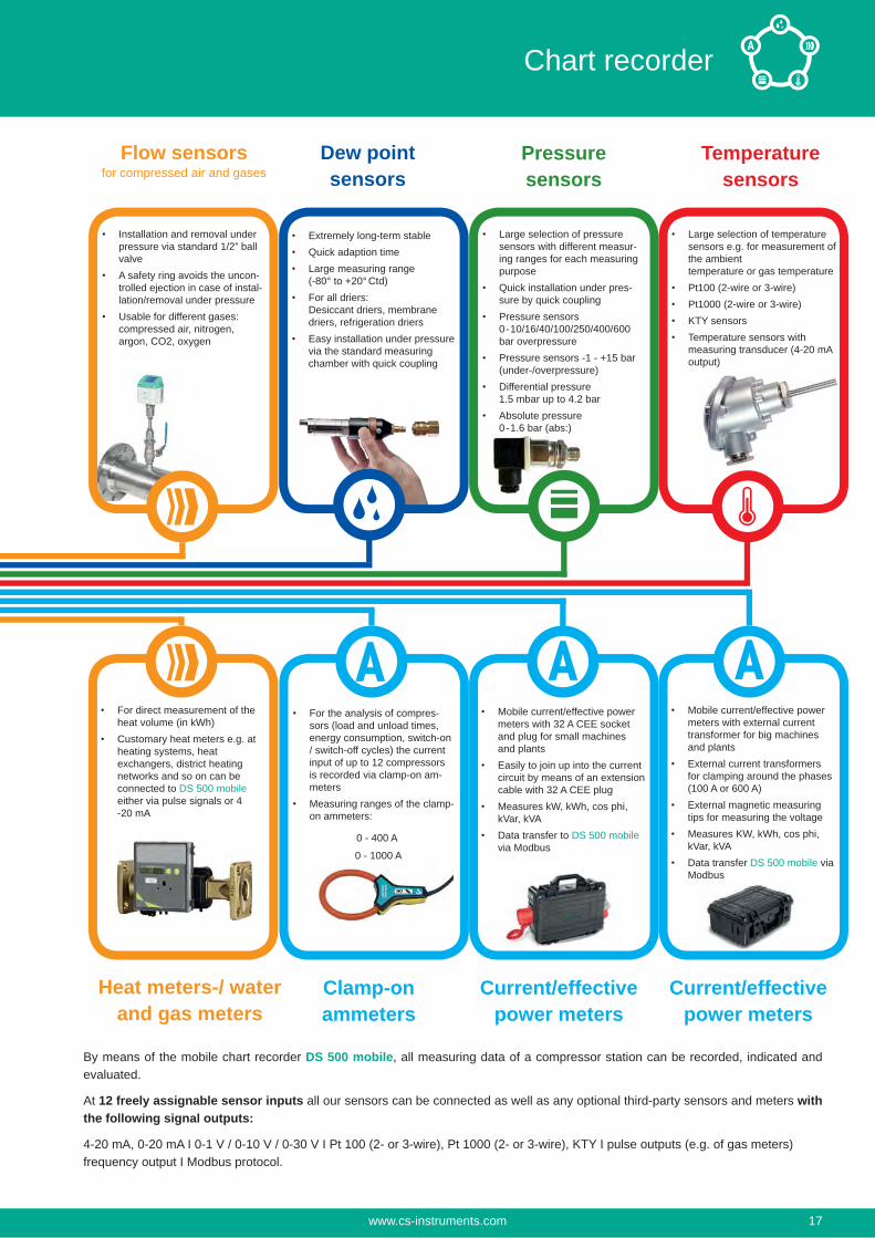
Mobile current/effective power meters with external current transformer for big machines and plantsExternal current transformers for clamping around the phases (100 A or 600 A)External magnetic measuring tips for measuring the voltageMeasures KW, kWh, cos phi, kVar, kVAData transfer DS 500 mobile via Modbus
Installation and removal under pressure via standard 1/2” ball valveA safety ring avoids the uncon-trolled ejection in case of instal-lation/removal under pressureUsable for different gases: compressed air, nitrogen, argon, CO2, oxygen
Flow sensorsfor compressed air and gases
Extremely long-term stableQuick adaption timeLarge measuring range (-80° to +20° Ctd)For all driers: Desiccant driers, membrane driers, refrigeration driersEasy installation under pressure via the standard measuring chamber with quick coupling
Dew point sensors
Large selection of pressure sensors with different measur-ing ranges for each measuring purposeQuick installation under pres-sure by quick couplingPressure sensors 0-10/16/40/100/250/400/600 bar overpressurePressure sensors -1 - +15 bar (under-/overpressure)Differential pressure 1.5 mbar up to 4.2 barAbsolute pressure 0-1.6 bar (abs:)
Pressure sensors
Large selection of temperature sensors e.g. for measurement of the ambient temperature or gas temperaturePt100 (2-wire or 3-wire)Pt1000 (2-wire or 3-wire)KTY sensorsTemperature sensors with measuring transducer (4-20 mA output)
Temperature sensors
For direct measurement of the heat volume (in kWh)Customary heat meters e.g. at heating systems, heat exchangers, district heating networks and so on can be connected to DS 500 mobile either via pulse signals or 4 -20 mA
Heat meters-/ water and gas meters
Current/effective power meters
Current/effective power meters
Clamp-on ammeters
Mobile current/effective power meters with 32 A CEE socket and plug for small machines and plantsEasily to join up into the current circuit by means of an extension cable with 32 A CEE plugMeasures kW, kWh, cos phi, kVar, kVAData transfer to DS 500 mobile via Modbus
For the analysis of compres-sors (load and unload times, energy consumption, switch-on / switch-off cycles) the current input of up to 12 compressors is recorded via clamp-on am-metersMeasuring ranges of the clamp-on ammeters:
0 - 400 A
0 - 1000 A
By means of the mobile chart recorder DS 500 mobile, all measuring data of a compressor station can be recorded, indicated and evaluated.
At 12 freely assignable sensor inputs all our sensors can be connected as well as any optional third-party sensors and meters with the following signal outputs:
4-20 mA, 0-20 mA I 0-1 V / 0-10 V / 0-30 V I Pt 100 (2- or 3-wire), Pt 1000 (2- or 3-wire), KTY I pulse outputs (e.g. of gas meters) frequency output I Modbus protocol.
www.cs-instruments.com 17
Chart recorder
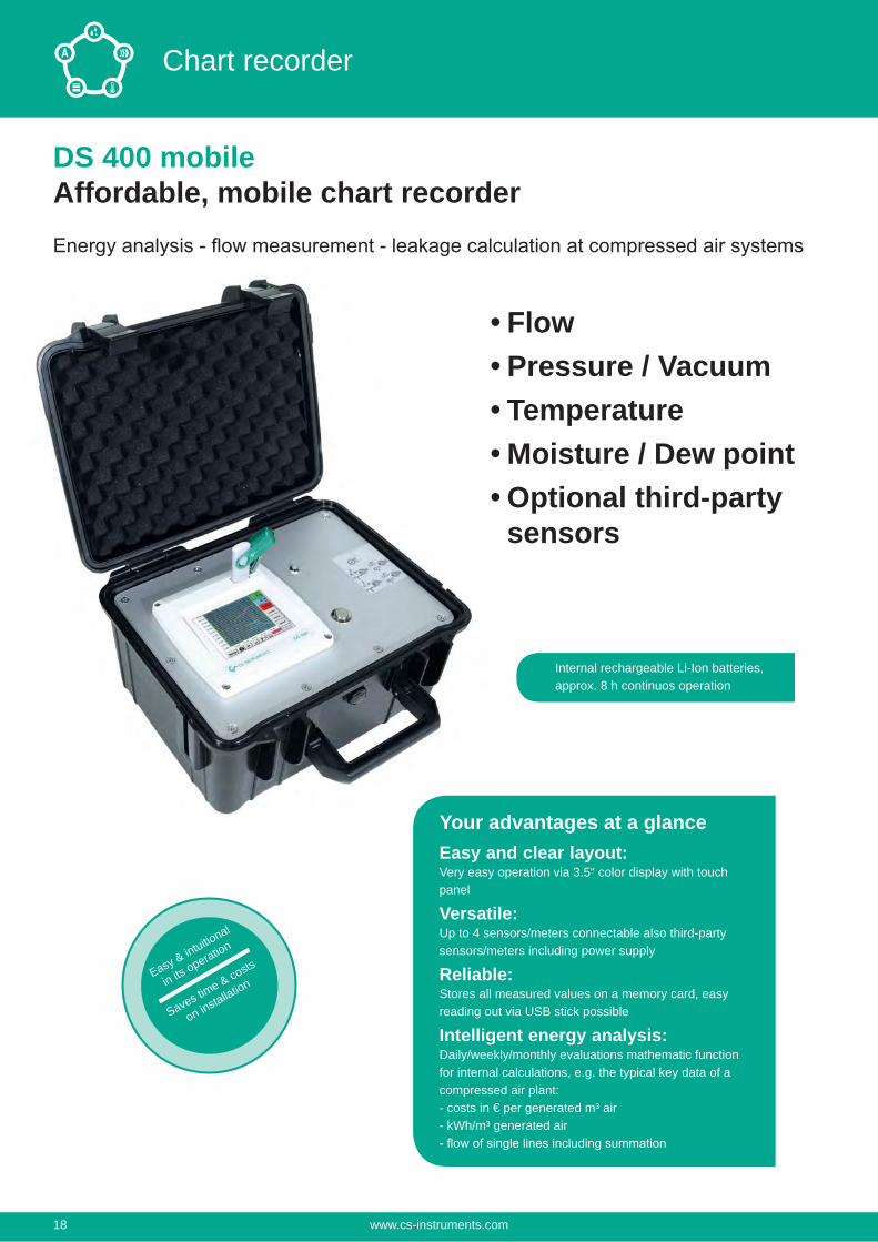
DS 400 mobileAffordable, mobile chart recorder
Your advantages at a glanceEasy and clear layout:Very easy operation via 3.5“ color display with touch panel
Versatile:Up to 4 sensors/meters connectable also third-party sensors/meters including power supply
Reliable:Stores all measured values on a memory card, easy reading out via USB stick possible
Intelligent energy analysis:Daily/weekly/monthly evaluations mathematic function for internal calculations, e.g. the typical key data of a compressed air plant:- costs in € per generated m³ air- kWh/m³ generated air
Internal rechargeable Li-Ion batteries, approx. 8 h continuos operation
FlowPressure / VacuumTemperatureMoisture / Dew pointOptional third-party sensors
Easy & intuitional
in its operation
Saves time & costs
on installation
www.cs-instruments.com18
Chart recorder
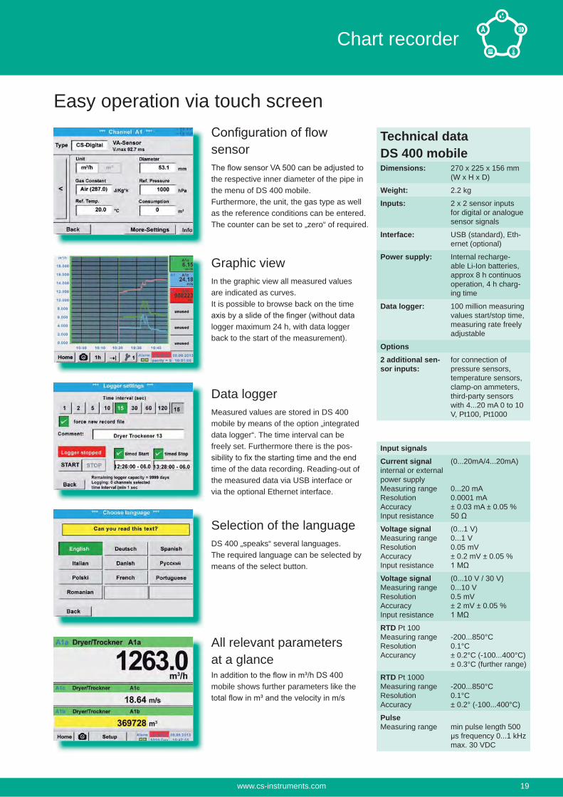
sensor
the respective inner diameter of the pipe in the menu of DS 400 mobile.Furthermore, the unit, the gas type as well as the reference conditions can be entered.The counter can be set to „zero“ of required.
Graphic viewIn the graphic view all measured values are indicated as curves.It is possible to browse back on the time
logger maximum 24 h, with data logger back to the start of the measurement).
Data loggerMeasured values are stored in DS 400 mobile by means of the option „integrated data logger“. The time interval can be freely set. Furthermore there is the pos-
time of the data recording. Reading-out of the measured data via USB interface or via the optional Ethernet interface.
Selection of the languageDS 400 „speaks“ several languages.The required language can be selected by means of the select button.
All relevant parameters at a glance
mobile shows further parameters like the
Easy operation via touch screen
Input signalsCurrent signalinternal or external power supplyMeasuring rangeResolutionAccuracyInput resistance
(0...20mA/4...20mA)
0...20 mA0.0001 mA± 0.03 mA ± 0.05 %
Voltage signalMeasuring rangeResolutionAccuracyInput resistance
(0...1 V)0...1 V0.05 mV± 0.2 mV ± 0.05 %
Voltage signalMeasuring rangeResolutionAccuracyInput resistance
(0...10 V / 30 V)0...10 V0.5 mV± 2 mV ± 0.05 %
RTD Pt 100Measuring rangeResolutionAccurancy
-200...850°C0.1°C± 0.2°C (-100...400°C)± 0.3°C (further range)
RTD Pt 1000Measuring rangeResolutionAccuracy
-200...850°C0.1°C± 0.2° (-100...400°C)
PulseMeasuring range min pulse length 500
μs frequency 0...1 kHzmax. 30 VDC
Technical data DS 400 mobileDimensions: 270 x 225 x 156 mm
(W x H x D)
Weight: 2.2 kg
Inputs: 2 x 2 sensor inputs for digital or analogue sensor signals
Interface: USB (standard), Eth-ernet (optional)
Power supply: Internal recharge-able Li-Ion batteries, approx 8 h continuos operation, 4 h charg-ing time
Data logger: 100 million measuring values start/stop time, measuring rate freely adjustable
Options2 additional sen-sor inputs:
for connection of pressure sensors, temperature sensors, clamp-on ammeters, third-party sensors with 4...20 mA 0 to 10 V, Pt100, Pt1000
www.cs-instruments.com 19
Chart recorder
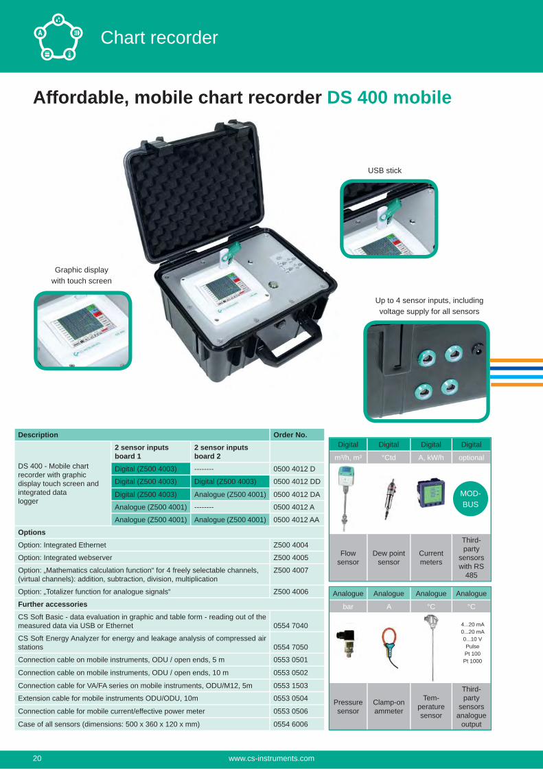
Graphic displaywith touch screen
USB stick
Up to 4 sensor inputs, includingvoltage supply for all sensors
Affordable, mobile chart recorder DS 400 mobile
Description Order No.
DS 400 - Mobile chart recorder with graphic display touch screen and integrated data logger
2 sensor inputs board 1
2 sensor inputs board 2
Digital (Z500 4003) -------- 0500 4012 D
Digital (Z500 4003) Digital (Z500 4003) 0500 4012 DD
Digital (Z500 4003) Analogue (Z500 4001) 0500 4012 DA
Analogue (Z500 4001) -------- 0500 4012 A
Analogue (Z500 4001) Analogue (Z500 4001) 0500 4012 AA
OptionsOption: Integrated Ethernet Z500 4004
Option: Integrated webserver Z500 4005
Option: „Mathematics calculation function“ for 4 freely selectable channels, (virtual channels): addition, subtraction, division, multiplication
Z500 4007
Option: „Totalizer function for analogue signals“ Z500 4006
Further accessoriesCS Soft Basic - data evaluation in graphic and table form - reading out of the measured data via USB or Ethernet 0554 7040
CS Soft Energy Analyzer for energy and leakage analysis of compressed air stations 0554 7050
Connection cable on mobile instruments, ODU / open ends, 5 m 0553 0501
Connection cable on mobile instruments, ODU / open ends, 10 m 0553 0502
Connection cable for VA/FA series on mobile instruments, ODU/M12, 5m 0553 1503
Extension cable for mobile instruments ODU/ODU, 10m 0553 0504
Connection cable for mobile current/effective power meter 0553 0506
Case of all sensors (dimensions: 500 x 360 x 120 x mm) 0554 6006
Digital Digital Digital Digital
m³/h, m³ °Ctd A, kW/h optional
Flow sensor
Dew point sensor
Current meters
Third-party
sensors with RS
485
MOD-BUS
Analogue Analogue Analogue Analogue
bar A °C °C
Pressure sensor
Clamp-on ammeter
Tem-perature sensor
Third-party
sensors analogue
output
4...20 mA 0...20 mA0...10 VPulsePt 100Pt 1000
www.cs-instruments.com20
Chart recorder
Digital Digital Analogue Analogue
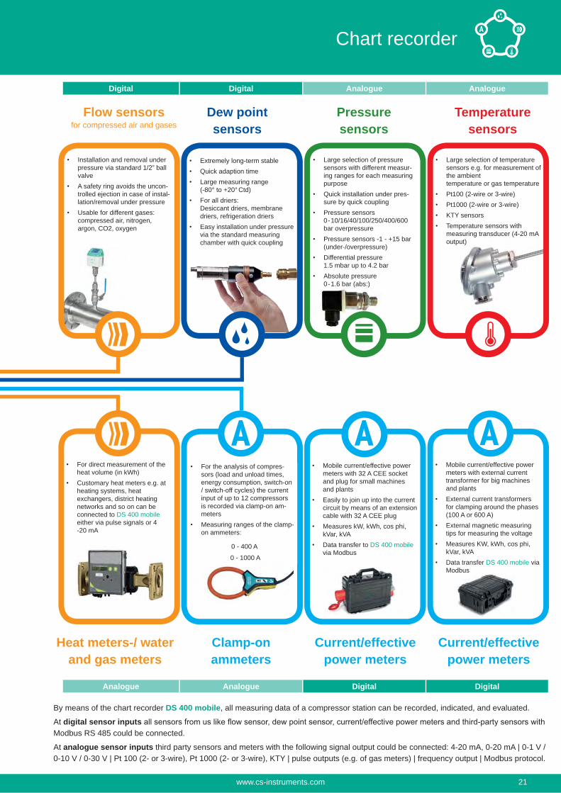
Mobile current/effective power meters with external current transformer for big machines and plantsExternal current transformers for clamping around the phases (100 A or 600 A)External magnetic measuring tips for measuring the voltageMeasures KW, kWh, cos phi, kVar, kVAData transfer DS 400 mobile via Modbus
Installation and removal under pressure via standard 1/2” ball valveA safety ring avoids the uncon-trolled ejection in case of instal-lation/removal under pressureUsable for different gases: compressed air, nitrogen, argon, CO2, oxygen
Flow sensorsfor compressed air and gases
Extremely long-term stableQuick adaption timeLarge measuring range (-80° to +20° Ctd)For all driers: Desiccant driers, membrane driers, refrigeration driersEasy installation under pressure via the standard measuring chamber with quick coupling
Dew point sensors
Large selection of pressure sensors with different measur-ing ranges for each measuring purposeQuick installation under pres-sure by quick couplingPressure sensors 0-10/16/40/100/250/400/600 bar overpressurePressure sensors -1 - +15 bar (under-/overpressure)Differential pressure 1.5 mbar up to 4.2 barAbsolute pressure 0-1.6 bar (abs:)
Pressure sensors
Large selection of temperature sensors e.g. for measurement of the ambient temperature or gas temperaturePt100 (2-wire or 3-wire)Pt1000 (2-wire or 3-wire)KTY sensorsTemperature sensors with measuring transducer (4-20 mA output)
Temperature sensors
For direct measurement of the heat volume (in kWh)Customary heat meters e.g. at heating systems, heat exchangers, district heating networks and so on can be connected to DS 400 mobile either via pulse signals or 4 -20 mA
Heat meters-/ water and gas meters
Current/effective power meters
Current/effective power meters
Clamp-on ammeters
Mobile current/effective power meters with 32 A CEE socket and plug for small machines and plantsEasily to join up into the current circuit by means of an extension cable with 32 A CEE plugMeasures kW, kWh, cos phi, kVar, kVAData transfer to DS 400 mobile via Modbus
For the analysis of compres-sors (load and unload times, energy consumption, switch-on / switch-off cycles) the current input of up to 12 compressors is recorded via clamp-on am-metersMeasuring ranges of the clamp-on ammeters:
0 - 400 A
0 - 1000 A
By means of the chart recorder DS 400 mobile, all measuring data of a compressor station can be recorded, indicated, and evaluated.
At digital sensor inputs Modbus RS 485 could be connected.
At analogue sensor inputs third party sensors and meters with the following signal output could be connected: 4-20 mA, 0-20 mA | 0-1 V / 0-10 V / 0-30 V | Pt 100 (2- or 3-wire), Pt 1000 (2- or 3-wire), KTY | pulse outputs (e.g. of gas meters) | frequency output | Modbus protocol.
Analogue Analogue Digital Digital
www.cs-instruments.com 21
Chart recorder
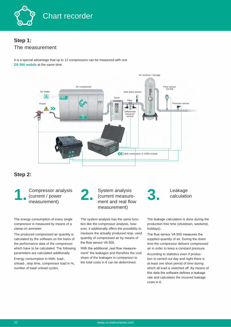
Step 1:The measurement
It is a special advantage that up to 12 compressors can be measured with one DS 500 mobile at the same time.
Step 2:
Air receiver / storage
Flow sensor VA 500
Pressure sensorFilter
Dryer
Dew point sensorAir intake
Power
1. Compressor analysis (current / power measurement)
2. System analysis(current measure-ment and real flow measurement)
3. Leakagecalculation
The energy consumption of every single compressor is measured by means of a clamp-on ammeter.
The produced compressed air quantity is calculated by the software on the basis of the performance data of the compressor which have to be calculated. The following parameters are calculated additionally.
Energy consumption in kWh, load-, unload-, stop time, compressor load in %, number of load/ unload cycles.
The system analysis has the same func-tion like the compressor analysis, how-ever, it additionally offers the possibility to measure the actually produced resp. used quantity of compressed air by means of
-ment“ the leakages and therefore the cost share of the leakages in comparison to the total costs in € can be determined.
The leakage calculation is done during the production free time (shutdown, weekend, holidays).
supplied quantity of air. During the down time the compressor delivers compressed air in order to keep a constant pressure.
According to statistics even if produc-tion is carried out day and night there is at least one short period of time during which all load is switched off. By means of
rate and calculates the incurred leakage costs in €.
Cable connection or GSM module
Air compressor
Differentialpressuresensor
www.cs-instruments.com22
Chart recorder
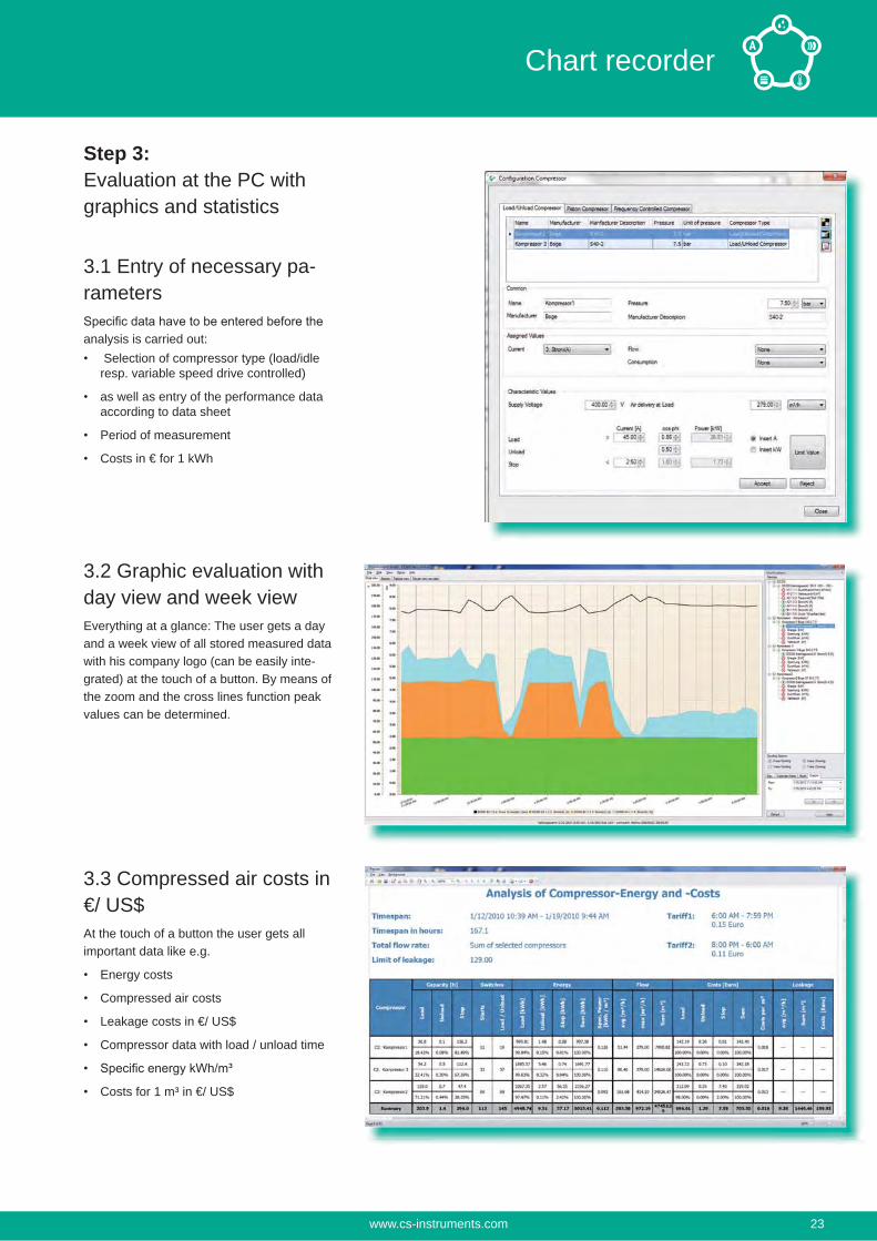
Step 3:Evaluation at the PC withgraphics and statistics
3.1 Entry of necessary pa-rameters
analysis is carried out: Selection of compressor type (load/idle resp. variable speed drive controlled)
as well as entry of the performance data according to data sheet
Period of measurement
Costs in € for 1 kWh
3.2 Graphic evaluation with day view and week viewEverything at a glance: The user gets a day and a week view of all stored measured data with his company logo (can be easily inte-grated) at the touch of a button. By means of the zoom and the cross lines function peak values can be determined.
3.3 Compressed air costs in €/ US$At the touch of a button the user gets all important data like e.g.
Energy costs
Compressed air costs
Leakage costs in €/ US$
Compressor data with load / unload time
Costs for 1 m³ in €/ US$
www.cs-instruments.com 23
Chart recorder
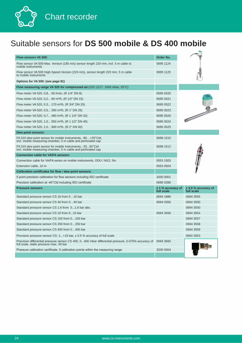
Suitable sensors for DS 500 mobile & DS 400 mobileFlow sensors VA 500: Order No.
Flow sensor VA 500-Max. Version (185 m/s) sensor length 220 mm, incl. 5 m cable to mobile instruments
0695 1124
Flow sensor VA 500 High-Speed Version (224 m/s), sensor length 220 mm, 5 m cable to mobile instruments
0695 1125
Options for VA 500: (see page 81)
Flow measuring range VA 520 for compressed air:(ISO 1217: 1000 mbar, 20°C)
Flow meter VA 520, 0,8... 90 l/min, (R 1/4“ DN 8) 0695 0520
Flow meter VA 520, 0,2... 90 m³/h, (R 1/2“ DN 15) 0695 0521
Flow meter VA 520, 0,3... 170 m³/h, (R 3/4“ DN 20) 0695 0522
Flow meter VA 520, 0,5... 290 m³/h, (R 1“ DN 25) 0695 0523
Flow meter VA 520, 0,7... 480 m³/h, (R 1 1/4“ DN 32) 0695 0526
Flow meter VA 520, 1,0... 550 m³/h, (R 1 1/2“ DN 40) 0695 0524
Flow meter VA 520, 2,0... 900 m³/h, (R 2“ DN 50) 0695 0525
Dew point sensors:
FA 510 dew point sensor for mobile instruments, -80…+20°Ctd,incl. mobile measuring chamber, 5 m cable and perforated cap
0699 1510
FA 510 dew point sensor for mobile instruments, -20...50°Ctdincl. mobile measuring chamber, 5 m cable and perforated cap
0699 1512
Connection cable for VA/FA sensors:
Connection cable for VA/FA series on mobile instruments, ODU / M12, 5m 0553 1503
Extension cable, 10 m 0553 0504
3200 0001
0699 3396
Pressure sensors: ± 1 % accuracy of full scale
± 0,5 % accuracy of full scale
Standard pressure sensor CS 16 from 0…16 bar 0694 1886 0694 3555
Standard pressure sensor CS 40 from 0…40 bar 0694 0356 0694 3930
Standard pressure sensor CS 1.6 from 0...1.6 bar abs. 0694 3550
Standard pressure sensor CS 10 from 0...10 bar 0694 3556 0694 3554
Standard pressure sensor CS 100 from 0…100 bar 0694 3557
Standard pressure sensor CS 250 from 0…250 bar 0694 3558
Standard pressure sensor CS 400 from 0…400 bar 0694 3559
Precision pressure sensor CS -1...+15 bar, ± 0.5 % accuracy of full scale 0694 3553
Precision differential pressure sensor CS 400, 0...400 mbar differential pressure, 0.075% accuracy of full scale, static pressure max. 40 bar
0694 3560
3200 0004
www.cs-instruments.com24
Chart recorder
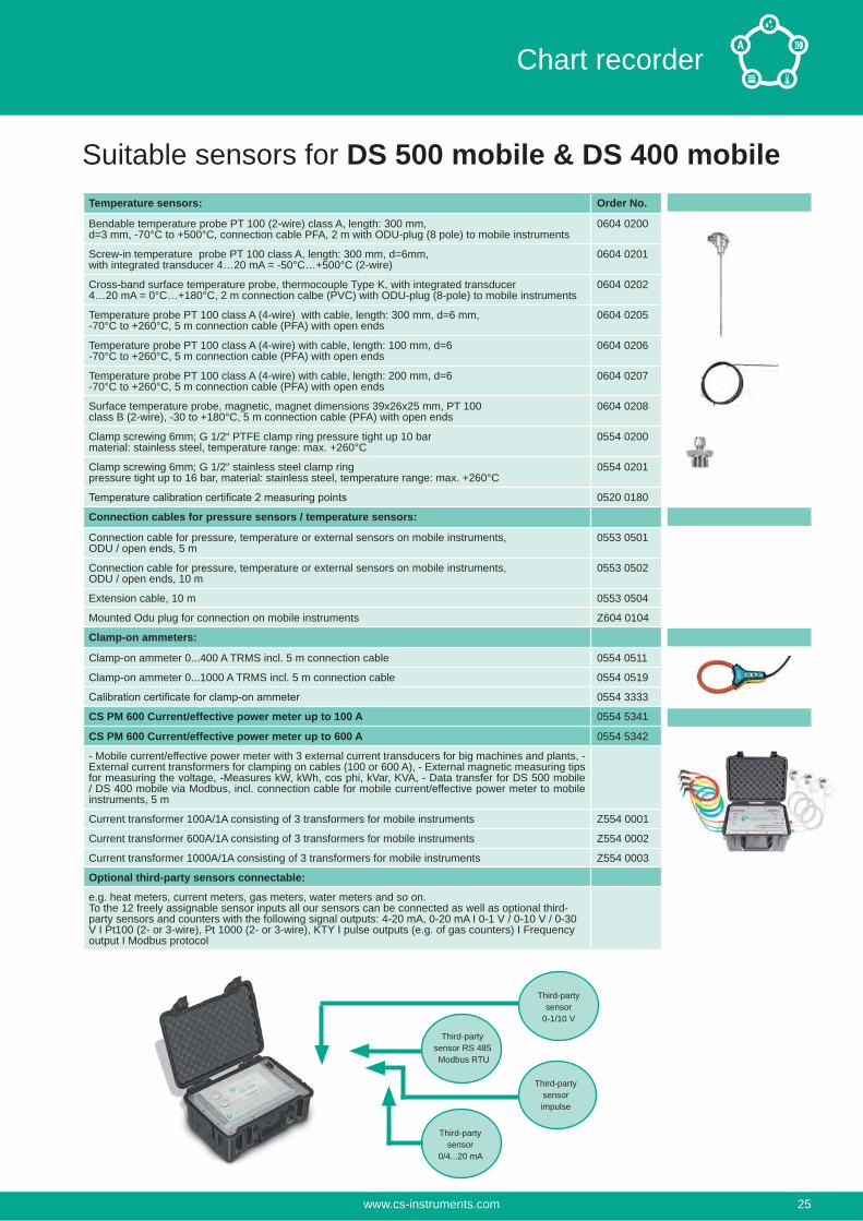
Temperature sensors: Order No.
Bendable temperature probe PT 100 (2-wire) class A, length: 300 mm,d=3 mm, -70°C to +500°C, connection cable PFA, 2 m with ODU-plug (8 pole) to mobile instruments
0604 0200
Screw-in temperature probe PT 100 class A, length: 300 mm, d=6mm,with integrated transducer 4…20 mA = -50°C…+500°C (2-wire)
0604 0201
Cross-band surface temperature probe, thermocouple Type K, with integrated transducer 4…20 mA = 0°C…+180°C, 2 m connection calbe (PVC) with ODU-plug (8-pole) to mobile instruments
0604 0202
Temperature probe PT 100 class A (4-wire) with cable, length: 300 mm, d=6 mm,-70°C to +260°C, 5 m connection cable (PFA) with open ends
0604 0205
Temperature probe PT 100 class A (4-wire) with cable, length: 100 mm, d=6-70°C to +260°C, 5 m connection cable (PFA) with open ends
0604 0206
Temperature probe PT 100 class A (4-wire) with cable, length: 200 mm, d=6-70°C to +260°C, 5 m connection cable (PFA) with open ends
0604 0207
Surface temperature probe, magnetic, magnet dimensions 39x26x25 mm, PT 100class B (2-wire), -30 to +180°C, 5 m connection cable (PFA) with open ends
0604 0208
Clamp screwing 6mm; G 1/2“ PTFE clamp ring pressure tight up 10 barmaterial: stainless steel, temperature range: max. +260°C
0554 0200
Clamp screwing 6mm; G 1/2“ stainless steel clamp ringpressure tight up to 16 bar, material: stainless steel, temperature range: max. +260°C
0554 0201
0520 0180
Connection cables for pressure sensors / temperature sensors:
Connection cable for pressure, temperature or external sensors on mobile instruments, ODU / open ends, 5 m
0553 0501
Connection cable for pressure, temperature or external sensors on mobile instruments, ODU / open ends, 10 m
0553 0502
Extension cable, 10 m 0553 0504
Mounted Odu plug for connection on mobile instruments Z604 0104
Clamp-on ammeters:
Clamp-on ammeter 0...400 A TRMS incl. 5 m connection cable 0554 0511
Clamp-on ammeter 0...1000 A TRMS incl. 5 m connection cable 0554 0519
0554 3333
CS PM 600 Current/effective power meter up to 100 A 0554 5341
CS PM 600 Current/effective power meter up to 600 A 0554 5342
- Mobile current/effective power meter with 3 external current transducers for big machines and plants, - External current transformers for clamping on cables (100 or 600 A), - External magnetic measuring tips for measuring the voltage, -Measures kW, kWh, cos phi, kVar, KVA, - Data transfer for DS 500 mobile / DS 400 mobile via Modbus, incl. connection cable for mobile current/effective power meter to mobile instruments, 5 m
Current transformer 100A/1A consisting of 3 transformers for mobile instruments Z554 0001
Current transformer 600A/1A consisting of 3 transformers for mobile instruments Z554 0002
Current transformer 1000A/1A consisting of 3 transformers for mobile instruments Z554 0003
Optional third-party sensors connectable:
e.g. heat meters, current meters, gas meters, water meters and so on.To the 12 freely assignable sensor inputs all our sensors can be connected as well as optional third-party sensors and counters with the following signal outputs: 4-20 mA, 0-20 mA I 0-1 V / 0-10 V / 0-30 V I Pt100 (2- or 3-wire), Pt 1000 (2- or 3-wire), KTY I pulse outputs (e.g. of gas counters) I Frequency output I Modbus protocol
Suitable sensors for DS 500 mobile & DS 400 mobile
Third-partysensor
0-1/10 V
Third-partysensor
0/4...20 mA
Third-partysensorimpulse
Third-partysensor RS 485 Modbus RTU
www.cs-instruments.com 25
Chart recorder
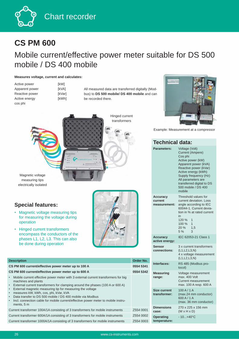
CS PM 600Mobile current/effective power meter suitable for DS 500 mobile / DS 400 mobile
All measured data are transferred digitally (Mod-bus) to DS 500 mobile/ DS 400 mobile and can be recorded there.
Example: Measurement at a compressor
Special features:Magnetic voltage measuring tips for measuring the voltage during operation
Hinged current transformers encompass the conductors of the phases L1, L2, L3. This can also be done during operation
Magnetic voltagemeasuring tips
electrically isolated
Hinged currenttransformers
Measures voltage, current and calculates:
Active power [kW]Apparent power [kVA]Reactive power [kVar]Active energy [kWh]cos phi
Description Order No.CS PM 600 current/effective power meter up to 100 A 0554 5341CS PM 600 current/effective power meter up to 600 A 0554 5342
Mobile current effective power meter with 3 external current transformers for big machines and plantsExternal current transformers for clamping around the phases (100 A or 600 A)External magnetic measuring tip for measuring the voltagemeasures kW, kWh, cos, phi, kVar, kVAData transfer to DS 500 mobile / DS 400 mobile via ModbusIncl. connection cable for mobile current/effective power meter to mobile instru-ments, 5 m
Current transformer 100A/1A consisting of 3 transformers for mobile instruments Z554 0001
Current transformer 600A/1A consisting of 3 transformers for mobile instruments Z554 0002
Current transformer 1000A/1A consisting of 3 transformers for mobile instruments Z554 0003
Technical data:Parameters: Voltage (Volt)
Current (Ampere)Cos phiActive power (kW)Apparent power (kVA)Reactive power (kVar)Active energy (kWh)Supply frequency (Hz)All parameters aretransferred digital to DS 500 mobile / DS 400 mobile
Accuracycurrentmeasurement:
Threshold values for current deviation. Loss angle according to IEC 60044-1. Current devia-tion in % at rated current in120 % 1100 % 120 % 1,55 % 3
Accuracyactive energy:
IEC 62053-21 Class 1
Sensor connections:
3 x current transformers (L1,L2,L3,N)4 x voltage measurement (L1,L2,L3,N)
Interfaces: RS 485 (Modbus pro-tocol)
Measuring range:
Voltage measurement max. 400 VoltCurrent measurement max. 100 A resp. 600 A
Size current transformer:
100 A / 1 A(max.24 mm conductor)600 A / 1 A(max. 36 mm conductor)
Dimensions case:
270 x 225 x 156 mm(W x H x D)
Operating temperature:
- 10...+40°C
www.cs-instruments.com26
Chart recorder
CS PM 210Current/ effective power meter for panel mountingMeasures voltage, current and calculates:
Active power [kW]Apparent power [kVA]Reactive power [kVar]Active energy [kWh]cos phi
All measured data are transferred digitally (Modbus) to DS 500 mobile/ DS 400 mobile and can be recorded there.
Voltage measurement
L1
L2
L3
N Current
transformers
Digital data transfer to DS 500/ DS 400 mobile
via RS 485 - Modbus
Description Order No.CS PM 210 current/effective power meter for panel mounting, current transform-er from 100 A to 2000 A connectable
0554 5353
Current transformer 100/5 A connectable to current/effective power meter for panel mounting (for cables up to Ø 21 mm)
0554 5344
Current transformer 200/5 A connectable to current/effective power meter for panel mounting (for cables up to Ø 21 mm)
0554 5345
Current transformer 300/5 A connectable to current/effective power meter for panel mounting (for cables up to Ø 22 mm)
0554 5346
Current transformer 500/5 A connectable to current/effective power meter for panel mounting (for cables up to Ø 22 mm)
0554 5347
Current transformer 600/5 A connectable to current/effective power meter for panel mounting (for cables up to Ø 22 mm)
0554 5348
Current transformer 1000/5 A connectable to current/effective power meter for panel mounting (for current bar up to 65 x 32 mm)
0554 5349
Current transformer 2000/5 A connectable to current/effective power meter for panel mounting (for current bar up to 127 x 38 mm)
0554 5350
Connection cable for pressure, temperature or external sensors on mobile instruments, ODU / open ends, 5 m
0553 0501
Connection cable for pressure, temperature or external sensors on mobile instruments, ODU / open ends, 10 m
0553 0502
Technical data:Parameters: Voltage (Volt)
Current (Ampere)Cos phiActive power (kW)Apparent power (kVA)Reactive power (kVar)Active energy (kWh)Supply frequency (Hz)All parameters aretransferred digitally to DS 500 mobile/ DS 400 mobile
Accuracycurrentmeasurement:
± 0,5% of 1 to 6 A
Accuracyvoltage:
± 0,5% of 50 V to 277 V
Accuracy active energy:
IEC 62053-21 Class 1
Interfaces: RS 485 (Modbus protocol)
Measuring range:
Voltage measurement max. 480 Volt
Dimensions: 96 x 96 x 69 mm(W x H x D)
Operatingtemperature:
-5...+55°C
www.cs-instruments.com 27
Chart recorder
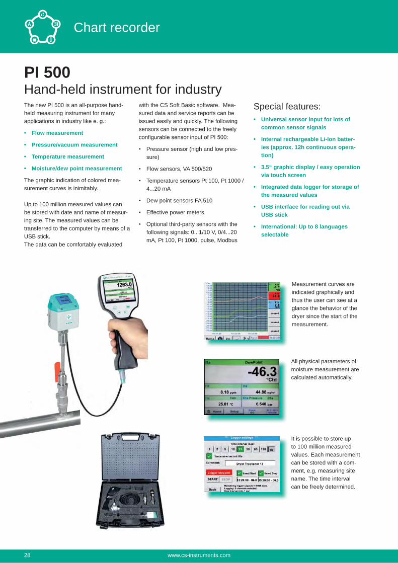
PI 500Hand-held instrument for industry
with the CS Soft Basic software. Mea-sured data and service reports can be issued easily and quickly. The following sensors can be connected to the freely
Pressure sensor (high and low pres-sure)
Flow sensors, VA 500/520
Temperature sensors Pt 100, Pt 1000 / 4...20 mA
Dew point sensors FA 510
Effective power meters
Optional third-party sensors with the following signals: 0...1/10 V, 0/4...20 mA, Pt 100, Pt 1000, pulse, Modbus
Special features:Universal sensor input for lots of common sensor signals
Internal rechargeable Li-Ion batter-ies (approx. 12h continuous opera-tion)
3.5“ graphic display / easy operation via touch screen
Integrated data logger for storage of the measured values
USB interface for reading out via USB stick
International: Up to 8 languages selectable
Measurement curves are indicated graphically and thus the user can see at a glance the behavior of the dryer since the start of the measurement.
All physical parameters of moisture measurement are calculated automatically.
It is possible to store up to 100 million measured values. Each measurement can be stored with a com-ment, e.g. measuring site name. The time interval can be freely determined.
The new PI 500 is an all-purpose hand-held measuring instrument for many applications in industry like e. g.:
Flow measurement
Pressure/vacuum measurement
Temperature measurement
Moisture/dew point measurement
The graphic indication of colored mea-surement curves is inimitably.
Up to 100 million measured values can be stored with date and name of measur-ing site. The measured values can be transferred to the computer by means of a USB stick. The data can be comfortably evaluated
www.cs-instruments.com28
Chart recorder
integratedUSB interface
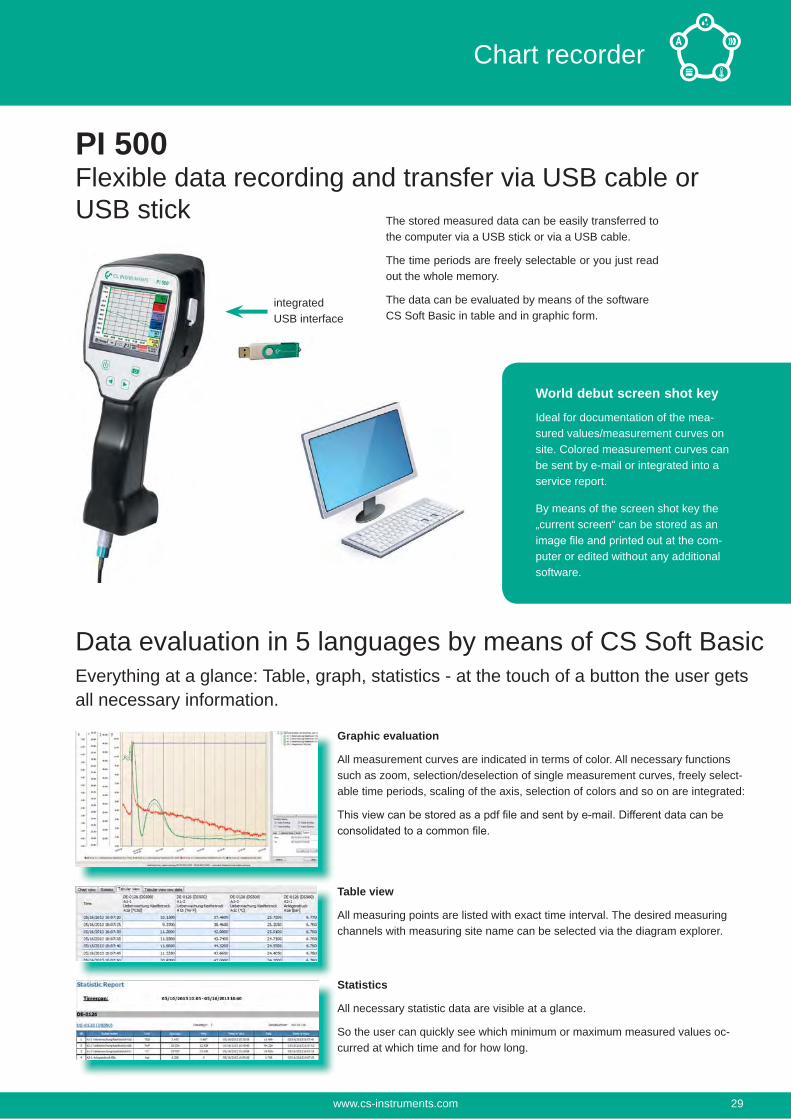
The stored measured data can be easily transferred to the computer via a USB stick or via a USB cable.
The time periods are freely selectable or you just read out the whole memory.
The data can be evaluated by means of the software CS Soft Basic in table and in graphic form.
PI 500Flexible data recording and transfer via USB cable or USB stick
Graphic evaluation
All measurement curves are indicated in terms of color. All necessary functions such as zoom, selection/deselection of single measurement curves, freely select-able time periods, scaling of the axis, selection of colors and so on are integrated:
Table view
All measuring points are listed with exact time interval. The desired measuring channels with measuring site name can be selected via the diagram explorer.
Statistics
All necessary statistic data are visible at a glance.
So the user can quickly see which minimum or maximum measured values oc-curred at which time and for how long.
Data evaluation in 5 languages by means of CS Soft BasicEverything at a glance: Table, graph, statistics - at the touch of a button the user gets all necessary information.
World debut screen shot key
Ideal for documentation of the mea-sured values/measurement curves on site. Colored measurement curves can be sent by e-mail or integrated into a service report.
By means of the screen shot key the „current screen“ can be stored as an
-puter or edited without any additional software.
www.cs-instruments.com 29
Chart recorder
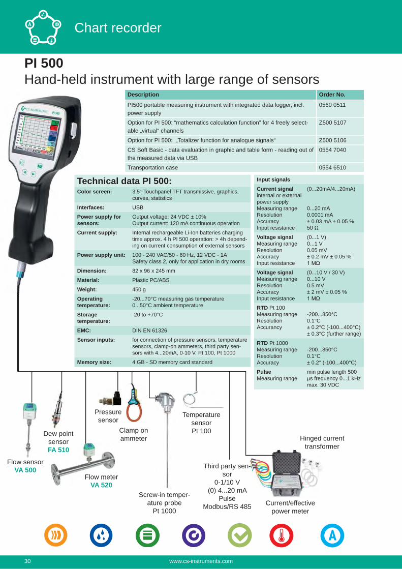
PI 500Hand-held instrument with large range of sensors
Flow meterVA 520
Pressure sensor
Clamp on ammeter
Screw-in temper-ature probe
Pt 1000
Temperature sensorPt 100
Current/effectivepower meter
Hinged current transformer
Flow sensorVA 500 Third party sen-
sor0-1/10 V
(0) 4...20 mAPulse
Modbus/RS 485
Flow meteVA 520
Dew point sensorFA 510
Description Order No.
PI500 portable measuring instrument with integrated data logger, incl. power supply
0560 0511
Option for PI 500: “mathematics calculation function” for 4 freely select-able „virtual“ channels
Z500 5107
Option for PI 500: „Totalizer function for analogue signals“ Z500 5106
CS Soft Basic - data evaluation in graphic and table form - reading out of the measured data via USB
0554 7040
Transportation case 0554 6510
Technical data PI 500:Color screen: 3.5“-Touchpanel TFT transmissive, graphics,
curves, statistics
Interfaces: USB
Power supply for sensors:
Output voltage: 24 VDC ± 10%Output current: 120 mA continuous operation
Current supply: Internal rechargeable Li-Ion batteries charging time approx. 4 h PI 500 operation: > 4h depend-ing on current consumption of external sensors
Power supply unit: 100 - 240 VAC/50 - 60 Hz, 12 VDC - 1ASafety class 2, only for application in dry rooms
Dimension: 82 x 96 x 245 mm
Material: Plastic PC/ABS
Weight: 450 g
Operating temperature:
-20...70°C measuring gas temperature0...50°C ambient temperature
Storage temperature:
-20 to +70°C
EMC: DIN EN 61326
Sensor inputs: for connection of pressure sensors, temperature sensors, clamp-on ammeters, third party sen-sors with 4...20mA, 0-10 V, Pt 100, Pt 1000
Memory size: 4 GB - SD memory card standard
Input signalsCurrent signalinternal or external power supplyMeasuring rangeResolutionAccuracyInput resistance
(0...20mA/4...20mA)
0...20 mA0.0001 mA± 0.03 mA ± 0.05 %
Voltage signalMeasuring rangeResolutionAccuracyInput resistance
(0...1 V)0...1 V0.05 mV± 0.2 mV ± 0.05 %
Voltage signalMeasuring rangeResolutionAccuracyInput resistance
(0...10 V / 30 V)0...10 V0.5 mV± 2 mV ± 0.05 %
RTD Pt 100Measuring rangeResolutionAccurancy
-200...850°C0.1°C± 0.2°C (-100...400°C)± 0.3°C (further range)
RTD Pt 1000Measuring rangeResolutionAccuracy
-200...850°C0.1°C± 0.2° (-100...400°C)
PulseMeasuring range
min pulse length 500 μs frequency 0...1 kHzmax. 30 VDC
www.cs-instruments.com30
Chart recorder
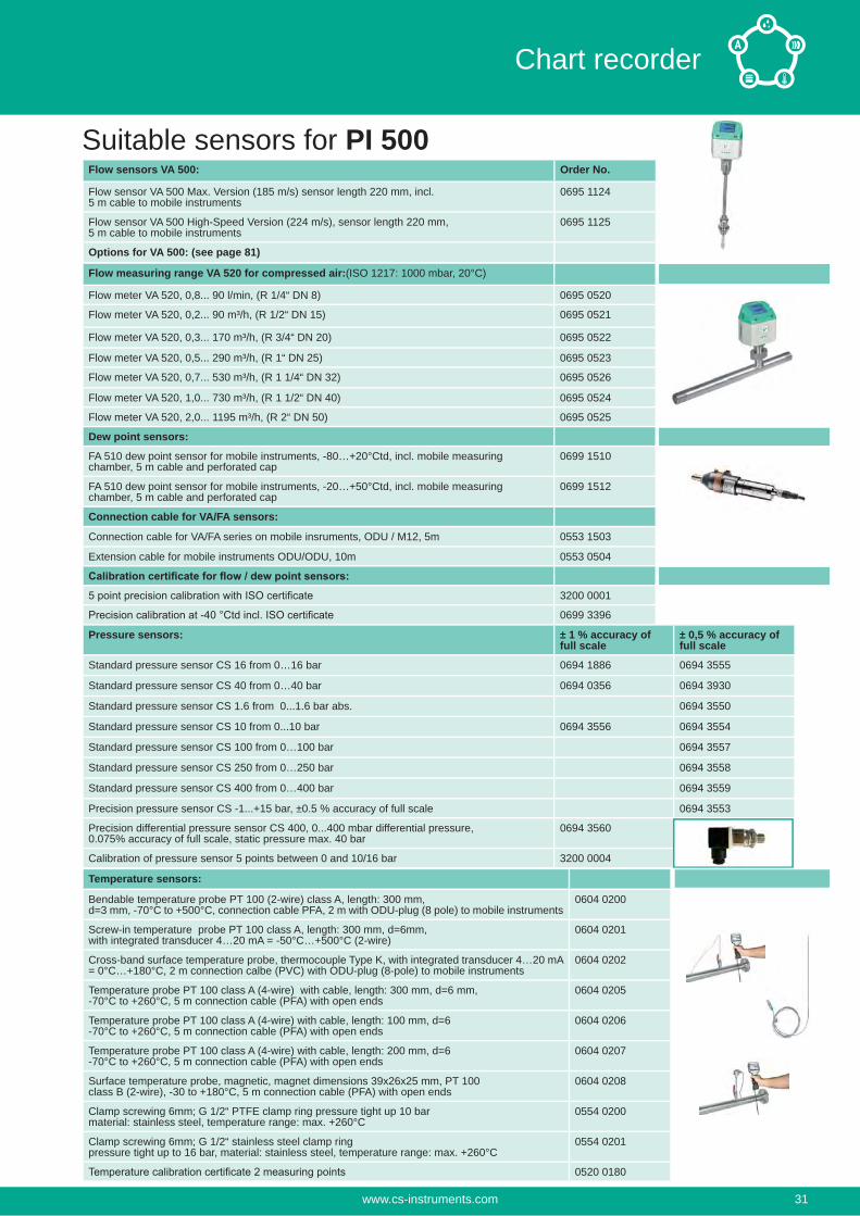
Flow sensors VA 500: Order No.
Flow sensor VA 500 Max. Version (185 m/s) sensor length 220 mm, incl. 5 m cable to mobile instruments
0695 1124
Flow sensor VA 500 High-Speed Version (224 m/s), sensor length 220 mm, 5 m cable to mobile instruments
0695 1125
Options for VA 500: (see page 81)
Flow measuring range VA 520 for compressed air:(ISO 1217: 1000 mbar, 20°C)
Flow meter VA 520, 0,8... 90 l/min, (R 1/4“ DN 8) 0695 0520
Flow meter VA 520, 0,2... 90 m³/h, (R 1/2“ DN 15) 0695 0521
Flow meter VA 520, 0,3... 170 m³/h, (R 3/4“ DN 20) 0695 0522
Flow meter VA 520, 0,5... 290 m³/h, (R 1“ DN 25) 0695 0523
Flow meter VA 520, 0,7... 530 m³/h, (R 1 1/4“ DN 32) 0695 0526
Flow meter VA 520, 1,0... 730 m³/h, (R 1 1/2“ DN 40) 0695 0524
Flow meter VA 520, 2,0... 1195 m³/h, (R 2“ DN 50) 0695 0525
Dew point sensors:
FA 510 dew point sensor for mobile instruments, -80…+20°Ctd, incl. mobile measuring chamber, 5 m cable and perforated cap
0699 1510
FA 510 dew point sensor for mobile instruments, -20…+50°Ctd, incl. mobile measuring chamber, 5 m cable and perforated cap
0699 1512
Connection cable for VA/FA sensors:
Connection cable for VA/FA series on mobile insruments, ODU / M12, 5m 0553 1503
Extension cable for mobile instruments ODU/ODU, 10m 0553 0504
3200 0001
0699 3396
Suitable sensors for PI 500
Pressure sensors: ± 1 % accuracy of full scale
± 0,5 % accuracy of full scale
Standard pressure sensor CS 16 from 0…16 bar 0694 1886 0694 3555
Standard pressure sensor CS 40 from 0…40 bar 0694 0356 0694 3930
Standard pressure sensor CS 1.6 from 0...1.6 bar abs. 0694 3550
Standard pressure sensor CS 10 from 0...10 bar 0694 3556 0694 3554
Standard pressure sensor CS 100 from 0…100 bar 0694 3557
Standard pressure sensor CS 250 from 0…250 bar 0694 3558
Standard pressure sensor CS 400 from 0…400 bar 0694 3559
Precision pressure sensor CS -1...+15 bar, ±0.5 % accuracy of full scale 0694 3553
Precision differential pressure sensor CS 400, 0...400 mbar differential pressure, 0.075% accuracy of full scale, static pressure max. 40 bar
0694 3560
Calibration of pressure sensor 5 points between 0 and 10/16 bar 3200 0004
Temperature sensors:
Bendable temperature probe PT 100 (2-wire) class A, length: 300 mm,d=3 mm, -70°C to +500°C, connection cable PFA, 2 m with ODU-plug (8 pole) to mobile instruments
0604 0200
Screw-in temperature probe PT 100 class A, length: 300 mm, d=6mm,with integrated transducer 4…20 mA = -50°C…+500°C (2-wire)
0604 0201
Cross-band surface temperature probe, thermocouple Type K, with integrated transducer 4…20 mA = 0°C…+180°C, 2 m connection calbe (PVC) with ODU-plug (8-pole) to mobile instruments
0604 0202
Temperature probe PT 100 class A (4-wire) with cable, length: 300 mm, d=6 mm,-70°C to +260°C, 5 m connection cable (PFA) with open ends
0604 0205
Temperature probe PT 100 class A (4-wire) with cable, length: 100 mm, d=6-70°C to +260°C, 5 m connection cable (PFA) with open ends
0604 0206
Temperature probe PT 100 class A (4-wire) with cable, length: 200 mm, d=6-70°C to +260°C, 5 m connection cable (PFA) with open ends
0604 0207
Surface temperature probe, magnetic, magnet dimensions 39x26x25 mm, PT 100class B (2-wire), -30 to +180°C, 5 m connection cable (PFA) with open ends
0604 0208
Clamp screwing 6mm; G 1/2“ PTFE clamp ring pressure tight up 10 barmaterial: stainless steel, temperature range: max. +260°C
0554 0200
Clamp screwing 6mm; G 1/2“ stainless steel clamp ringpressure tight up to 16 bar, material: stainless steel, temperature range: max. +260°C
0554 0201
0520 0180
www.cs-instruments.com 31
Chart recorder
Connection cables for pressure sensors / temperature sensors: Order No.Connection cable for pressure, temperature or external sensors on mobile instruments, ODU / open ends, 5 m
0553 0501
Connection cable for pressure, temperature or external sensors on mobile instruments, ODU / open ends, 10 m
0553 0502
Extension cable for mobile instruments, ODU / ODU, 10 m 0553 0504
Mounted Odu plug for connection on mobile instruments Z604 0104
Clamp-on ammeters:
Clamp-on ammeter 0...400 A TRMS incl. 5 m connection cable 0554 0511
Clamp-on ammeter 0...1000 A TRMS incl. 5 m connection cable 0554 0519
0554 3333
CS PM 600 Current/effective power meter up to 100 A 0554 5341
CS PM 600 Current/effective power meter up to 600 A 0554 5342
Mobile current/effective power meter with 3 external current transducers for big machines and plants xternal current transformers for clamping on cables (100 or 600 A)External magnetic measuring tips for measuring the voltageMeasures kW, kWh, cos phi, kVar, kVA Data transfer to PI 500 via ModbusIncl. connection cable for mobile current/effective power meter to mobile instruments, 5 m
Current transformer 100A/1A consisting of 3 transformers for mobile instruments Z554 0001
Current transformer 600A/1A consisting of 3 transformers for mobile instruments Z554 0002
Current transformer 1000A/1A consisting of 3 transformers for mobile instruments Z554 0003
Optional third-party sensors connectable:
e.g. heat meters, current meters, gas meters, water meters and so on.To the freely assignable sensor input all our sensors can be connected as well as optional third-party sensors and counters with the following signal outputs: 4-20 mA, 0-20 mA I 0-1 V / 0-10 V / 0-30 V I Pt100 (2- or 3-wire), Pt 1000 (2- or 3-wire), KTY I pulse outputs (e.g. of gas counters) I Frequency output I Modbus protocol
Suitable sensors for PI 500
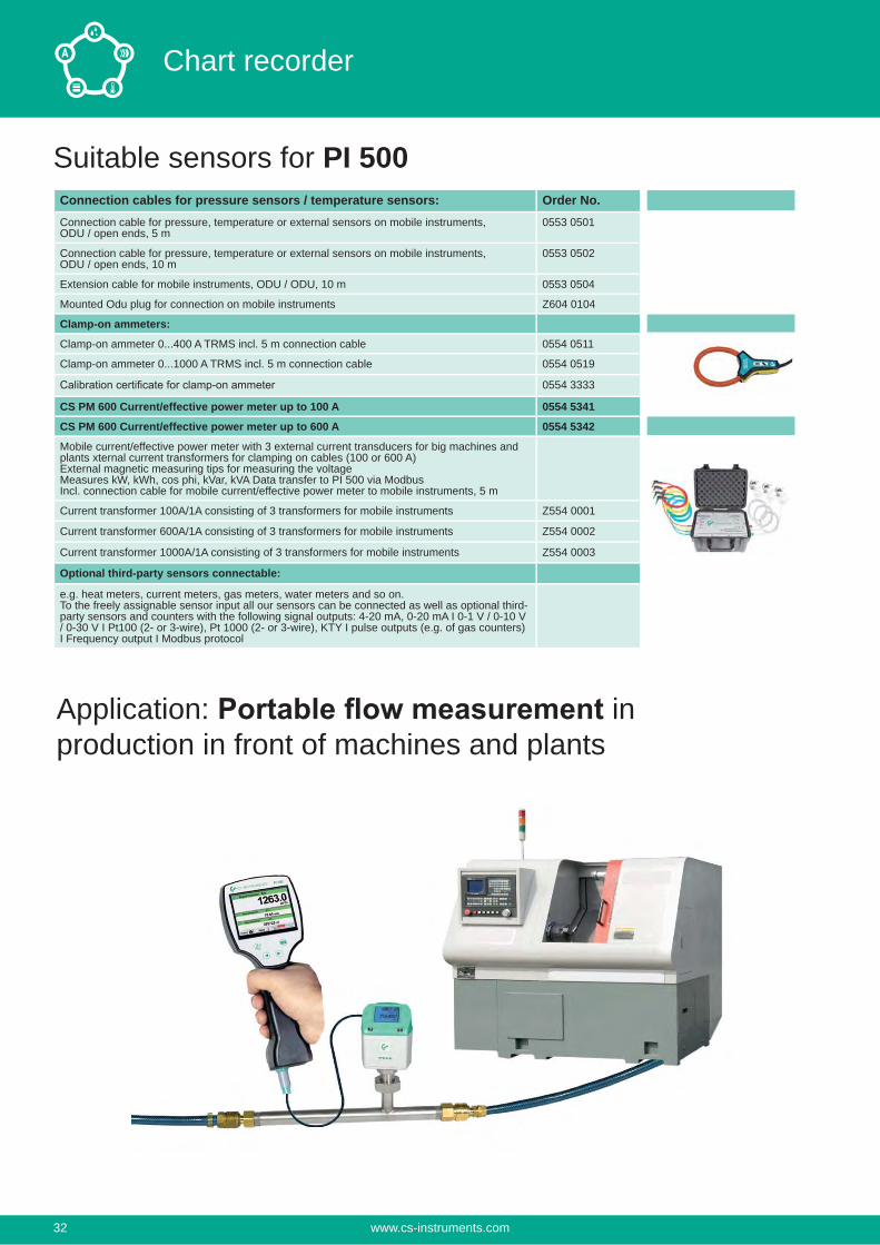
Application: in production in front of machines and plants
www.cs-instruments.com32
Chart recorder
1
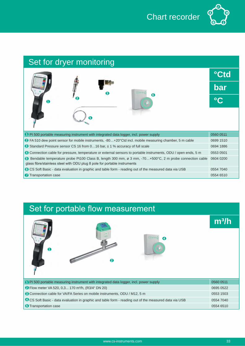
PI 500 portable measuring instrument with integrated data logger, incl. power supply 0560 0511
Flow meter VA 520, 0,3... 170 m³/h, (R3/4“ DN 20) 0695 0522
Connection cable for VA/FA Series on mobile instruments, ODU / M12, 5 m 0553 1503
CS Soft Basic - data evaluation in graphic and table form - reading out of the measured data via USB 0554 7040
Transportation case 0554 6510
m³/h
23
5
6
1
2
4
12
4
5
3
PI 500 portable measuring instrument with integrated data logger, incl. power supply 0560 0511
FA 510 dew point sensor for mobile instruments, -80…+20°Ctd incl. mobile measuring chamber, 5 m cable 0699 1510
Standard Pressure sensor CS 16 from 0…16 bar, ± 1 % accuracy of full scale 0694 1886
Connection cable for pressure, temperature or external sensors to portable instruments, ODU / open ends, 5 m 0553 0501
Bendable temperature probe Pt100 Class B, length 300 mm, ø 3 mm, -70…+500°C, 2 m probe connection cable 0604 0200
CS Soft Basic - data evaluation in graphic and table form - reading out of the measured data via USB 0554 7040
Transportation case 0554 6510
°Ctdbar°C
Set for dryer monitoring
3
4
5
6
7
1
2
www.cs-instruments.com 33
Chart recorder
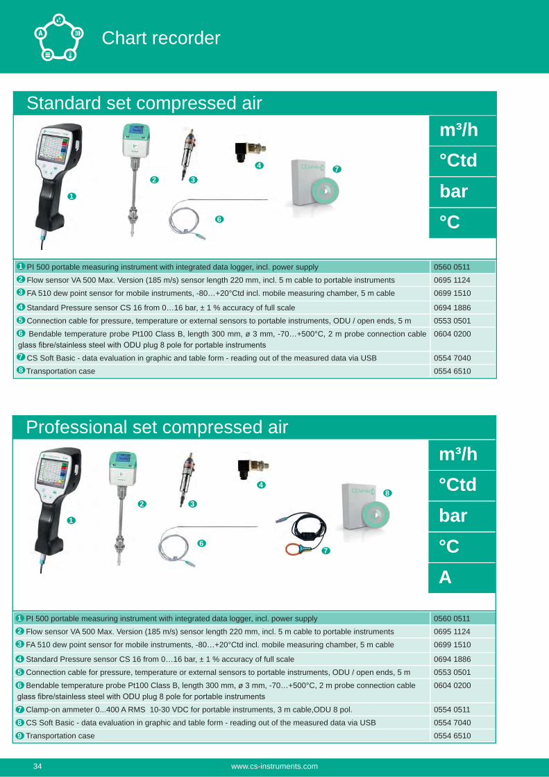
PI 500 portable measuring instrument with integrated data logger, incl. power supply 0560 0511
Flow sensor VA 500 Max. Version (185 m/s) sensor length 220 mm, incl. 5 m cable to portable instruments 0695 1124
FA 510 dew point sensor for mobile instruments, -80…+20°Ctd incl. mobile measuring chamber, 5 m cable 0699 1510
Standard Pressure sensor CS 16 from 0…16 bar, ± 1 % accuracy of full scale 0694 1886
Connection cable for pressure, temperature or external sensors to portable instruments, ODU / open ends, 5 m 0553 0501
Bendable temperature probe Pt100 Class B, length 300 mm, ø 3 mm, -70…+500°C, 2 m probe connection cable 0604 0200
CS Soft Basic - data evaluation in graphic and table form - reading out of the measured data via USB 0554 7040
Transportation case 0554 6510
Standard set compressed air
6
7
1
2
3
4
5
1
6
7
8
32
PI 500 portable measuring instrument with integrated data logger, incl. power supply 0560 0511
Flow sensor VA 500 Max. Version (185 m/s) sensor length 220 mm, incl. 5 m cable to portable instruments 0695 1124
FA 510 dew point sensor for mobile instruments, -80…+20°Ctd incl. mobile measuring chamber, 5 m cable 0699 1510
Standard Pressure sensor CS 16 from 0…16 bar, ± 1 % accuracy of full scale 0694 1886
Connection cable for pressure, temperature or external sensors to portable instruments, ODU / open ends, 5 m 0553 0501
Bendable temperature probe Pt100 Class B, length 300 mm, ø 3 mm, -70…+500°C, 2 m probe connection cable 0604 0200
Clamp-on ammeter 0...400 A RMS 10-30 VDC for portable instruments, 3 m cable,ODU 8 pol. 0554 0511
CS Soft Basic - data evaluation in graphic and table form - reading out of the measured data via USB 0554 7040
Transportation case 0554 6510
Professional set compressed air
6
8
1
2
3
4
5
1
6
7
8
3
4
2
9
7
m³/h°Ctdbar°C
m³/h°Ctdbar°CA
4
www.cs-instruments.com34
Chart recorder
Notes:
www.cs-instruments.com 35
Chart recorder
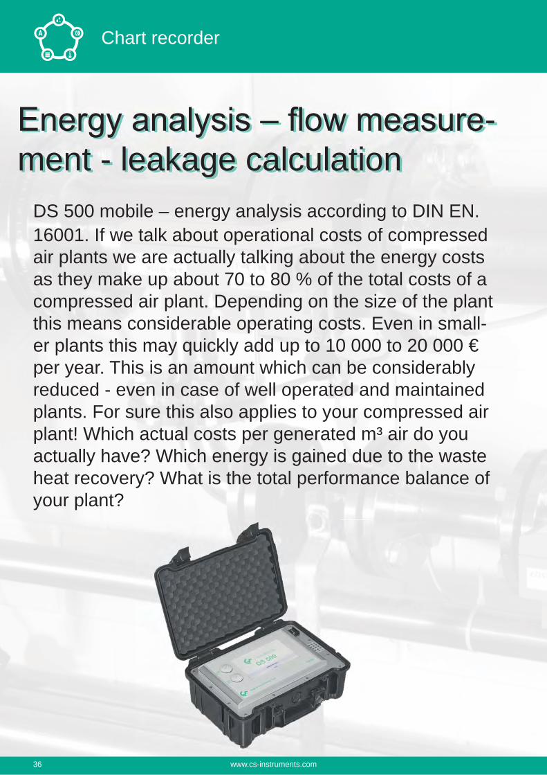
DS 500 mobile – energy analysis according to DIN EN. 16001. If we talk about operational costs of compressed air plants we are actually talking about the energy costs as they make up about 70 to 80 % of the total costs of a compressed air plant. Depending on the size of the plant this means considerable operating costs. Even in small-er plants this may quickly add up to 10 000 to 20 000 € per year. This is an amount which can be considerably reduced - even in case of well operated and maintained plants. For sure this also applies to your compressed air plant! Which actual costs per generated m³ air do you actually have? Which energy is gained due to the waste heat recovery? What is the total performance balance of your plant?
-ment - leakage calculation
www.cs-instruments.com36
Chart recorder
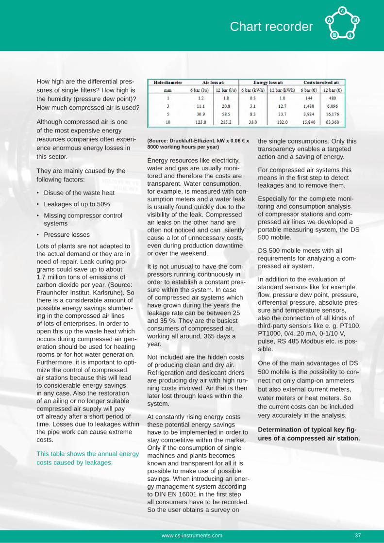
How high are the differential pres-sures of single filters? How high is the humidity (pressure dew point)? How much compressed air is used?
Although compressed air is one of the most expensive energy resources companies often experi-ence enormous energy losses in this sector.
They are mainly caused by the following factors:
Disuse of the waste heat
Leakages of up to 50%
Missing compressor control systems
Pressure losses
Lots of plants are not adapted to the actual demand or they are in need of repair. Leak curing pro-grams could save up to about 1.7 million tons of emissions of carbon dioxide per year. (Source: Fraunhofer Institut, Karlsruhe). So there is a considerable amount of possible energy savings slumber-ing in the compressed air lines of lots of enterprises. In order to open this up the waste heat which occurs during compressed air gen-eration should be used for heating rooms or for hot water generation. Furthermore, it is important to opti-mize the control of compressed air stations because this will lead to considerable energy savings in any case. Also the restoration of an ailing or no longer suitable compressed air supply will pay off already after a short period of time. Losses due to leakages within the pipe work can cause extreme costs.
This table shows the annual energy costs caused by leakages:
8000 working hours per year)
Energy resources like electricity, water and gas are usually moni-tored and therefore the costs are transparent. Water consumption, for example, is measured with con-sumption meters and a water leak is usually found quickly due to the visibility of the leak. Compressed air leaks on the other hand are often not noticed and can „silently“ cause a lot of unnecessary costs, even during production downtime or over the weekend.
It is not unusual to have the com-pressors running continuously in order to establish a constant pres-sure within the system. In case of compressed air systems which have grown during the years the leakage rate can be between 25 and 35 %. They are the busiest consumers of compressed air, working all around, 365 days a year.
Not included are the hidden costs of producing clean and dry air. Refrigeration and desiccant driers are producing dry air with high run-ning costs involved. Air that is then later lost through leaks within the system.
At constantly rising energy costs these potential energy savings have to be implemented in order to stay competitive within the market. Only if the consumption of single machines and plants becomes known and transparent for all it is possible to make use of possible savings. When introducing an ener-gy management system according to DIN EN 16001 in the first step all consumers have to be recorded. So the user obtains a survey on
the single consumptions. Only this transparency enables a targeted action and a saving of energy.
For compressed air systems this means in the first step to detect leakages and to remove them.
Especially for the complete moni-toring and consumption analysis of compressor stations and com-pressed air lines we developed a portable measuring system, the DS 500 mobile.
DS 500 mobile meets with all requirements for analyzing a com-pressed air system.
In addition to the evaluation of standard sensors like for example flow, pressure dew point, pressure, differential pressure, absolute pres-sure and temperature sensors, also the connection of all kinds of third-party sensors like e. g. PT100, PT1000, 0/4..20 mA, 0-1/10 V, pulse, RS 485 Modbus etc. is pos-sible.
One of the main advantages of DS 500 mobile is the possibility to con-nect not only clamp-on ammeters but also external current meters, water meters or heat meters. So the current costs can be included very accurately in the analysis.
Determination of typical key fig-ures of a compressed air station.
www.cs-instruments.com 37
Chart recorder
DS 500 mobile enables an intel-ligent energy analysis in a quick and easy way. The data will be indi-cated immediately in the display.
For this purpose just the costs in € per kWh (please consider day and night tariff) have to be entered.
By means of a mathematical function typical calculations can be carried out like for example
of compressed air
Consumption of single com-pressed air lines including summation
Indication of Min-Max values, average value
If the minimum values rise con-tinuously over the years this is a clear signal that the leakage rate increases. This can easily be deter-mined by carrying out the measure-ments in regular intervals.
Consumption analysis including statistics at the touch of a button
Besides the compressed air also all other energy costs like current, water, vapor etc. can be recorded in this evaluation. This creates transparency.
So all energy and flow meters for compressed air, gas, water, vapor and so on can be recorded and evaluated. The customer gets the costs in €uro. On the big 7“ color display with touch panel all infor-mation are visible at a glance. By means of the evaluation software CS Soft Basic all data can be eval-uated online at the PC via a USB stick or Ethernet. Additionally to the consumption analysis as daily/weekly or monthly report an alarm can be sent by e-mail or SMS in case of an exceeding of the thresh-old values. The measured data can be retrieved all over the world via the webserver, GSM module. How
is this done in practice?
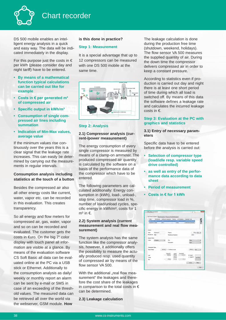
Step 1: Measurement
It is a special advantage that up to 12 compressors can be measured with one DS 500 mobile at the same time.
Step 2: Analysis
2.1) Compressor analysis (cur-rent-/power measurement)
The energy consumption of every single compressor is measured by means of a clamp-on ammeter. The produced compressed air quantity is calculated by the software on a basis of the performance data of the compressor which have to be entered.
The following parameters are cal-culated additionally: Energy con-sumption in (kWh), load-, unload-, stop time, compressor load in %, number of load/unload cycles, spe-cific energy in kWh/m³, costs for 1 m³ in €.
2.2) System analysis (current measurement and real flow mea-surement)
The system analysis has the same function like the compressor analy-sis, however, it additionally offers the possibility to measure the actu-ally produced resp. used quantity of compressed air by means of the flow sensor VA 500.
With the additional „real flow mea-surement“ the leakages and there-fore the cost share of the leakages in comparison to the total costs in € can be determined.
2.3) Leakage calculation
The leakage calculation is done during the production free time (shutdown, weekend, holidays). The flow sensor VA 500 measures the supplied quantity of air. During the down time the compressor delivers compressed air in order to keep a constant pressure.
According to statistics even if pro-duction is carried out day and night there is at least one short period of time during which all load is switched off. By means of this data the software defines a leakage rate and calculates the incurred leakage costs in €.
Step 3: Evaluation at the PC with graphics and statistics
3.1) Entry of necessary param-eters
Specific data have to be entered before the analysis is carried out:
Selection of compressor type (load/idle resp. variable speed drive controlled)
as well as entry of the perfor-mance data according to data sheet
Period of measurement
www.cs-instruments.com38
Chart recorder
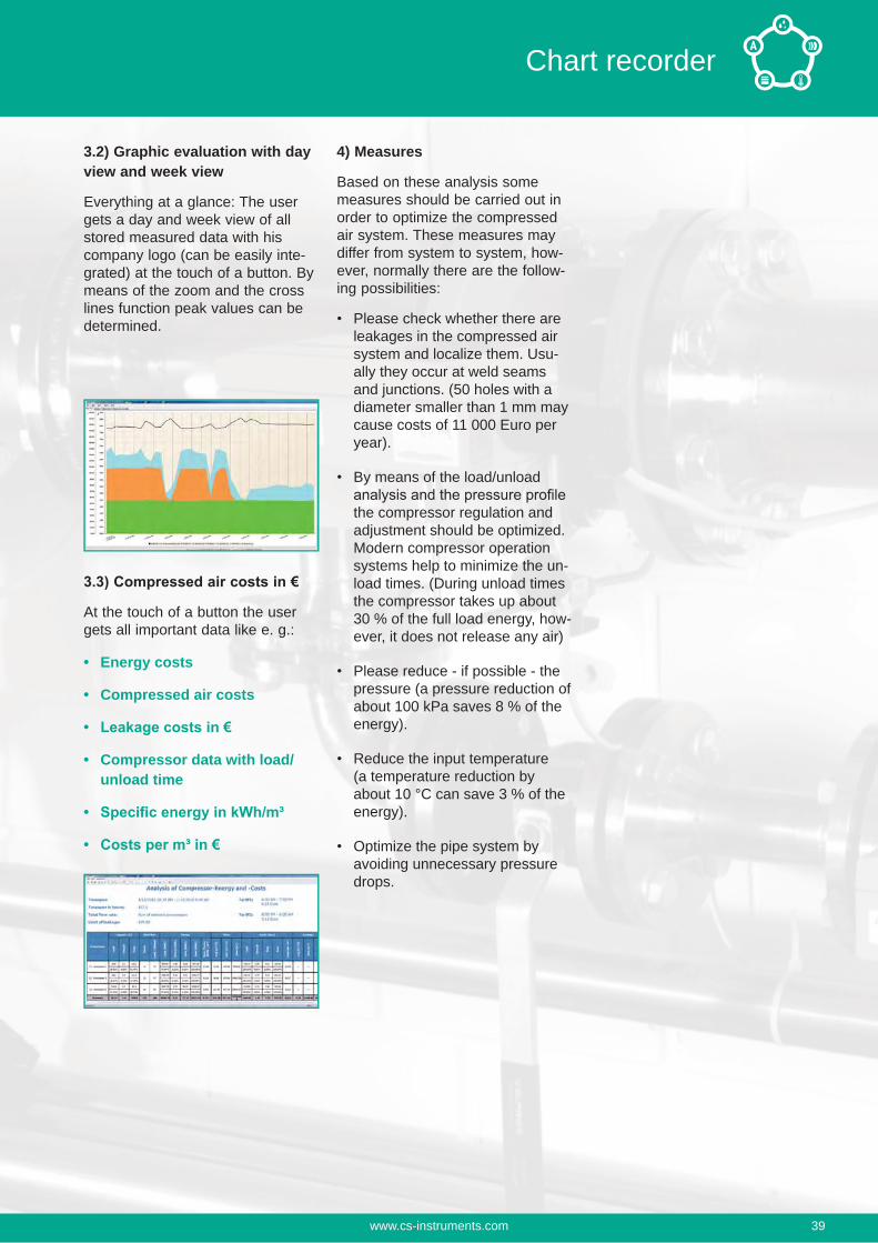
3.2) Graphic evaluation with day view and week view
Everything at a glance: The user gets a day and week view of all stored measured data with his company logo (can be easily inte-grated) at the touch of a button. By means of the zoom and the cross lines function peak values can be determined.
At the touch of a button the user gets all important data like e. g.:
Energy costs
Compressed air costs
Compressor data with load/ unload time
4) Measures
Based on these analysis some measures should be carried out in order to optimize the compressed air system. These measures may differ from system to system, how-ever, normally there are the follow-ing possibilities:
Please check whether there are leakages in the compressed air system and localize them. Usu-ally they occur at weld seams and junctions. (50 holes with a diameter smaller than 1 mm may cause costs of 11 000 Euro per year).
By means of the load/unload
the compressor regulation and adjustment should be optimized. Modern compressor operation systems help to minimize the un-load times. (During unload times the compressor takes up about 30 % of the full load energy, how-ever, it does not release any air)
Please reduce - if possible - the pressure (a pressure reduction of about 100 kPa saves 8 % of the energy).
Reduce the input temperature (a temperature reduction by about 10 °C can save 3 % of the energy).
Optimize the pipe system by avoiding unnecessary pressure drops.
www.cs-instruments.com 39
Chart recorder
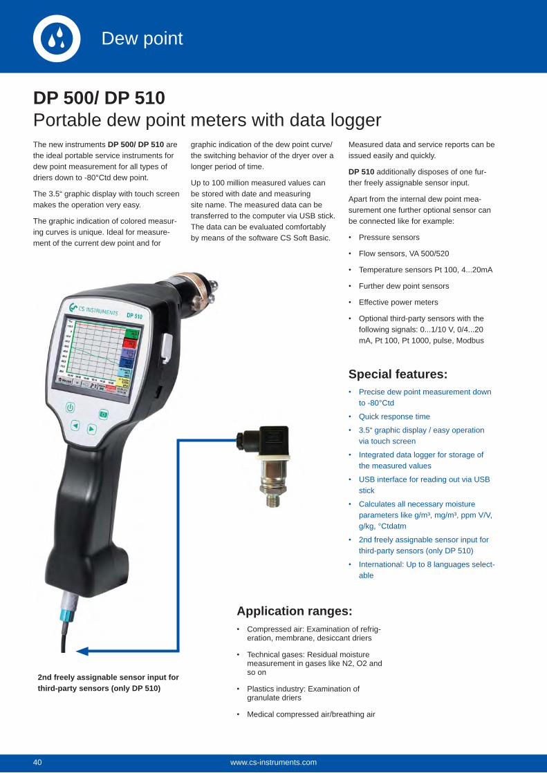
40
DP 500/ DP 510Portable dew point meters with data loggerThe new instruments DP 500/ DP 510 are the ideal portable service instruments for dew point measurement for all types of driers down to -80°Ctd dew point.
The 3.5“ graphic display with touch screen makes the operation very easy.
The graphic indication of colored measur-ing curves is unique. Ideal for measure-ment of the current dew point and for
graphic indication of the dew point curve/ the switching behavior of the dryer over a longer period of time.
Up to 100 million measured values can be stored with date and measuring site name. The measured data can be transferred to the computer via USB stick. The data can be evaluated comfortably by means of the software CS Soft Basic.
Measured data and service reports can be issued easily and quickly.
DP 510 additionally disposes of one fur-ther freely assignable sensor input.
Apart from the internal dew point mea-surement one further optional sensor can be connected like for example:
Pressure sensors
Flow sensors, VA 500/520
Temperature sensors Pt 100, 4...20mA
Further dew point sensors
Effective power meters
Optional third-party sensors with the following signals: 0...1/10 V, 0/4...20 mA, Pt 100, Pt 1000, pulse, Modbus
Special features:Precise dew point measurement down to -80°Ctd
Quick response time
3.5“ graphic display / easy operation via touch screen
Integrated data logger for storage of the measured values
USB interface for reading out via USB stick
Calculates all necessary moisture parameters like g/m³, mg/m³, ppm V/V, g/kg, °Ctdatm
2nd freely assignable sensor input for third-party sensors (only DP 510)
International: Up to 8 languages select-able
Application ranges:Compressed air: Examination of refrig-eration, membrane, desiccant driers
Technical gases: Residual moisture measurement in gases like N2, O2 and so on
Plastics industry: Examination of granulate driers
Medical compressed air/breathing air
2nd freely assignable sensor input for third-party sensors (only DP 510)
www.cs-instruments.com40
Dew point
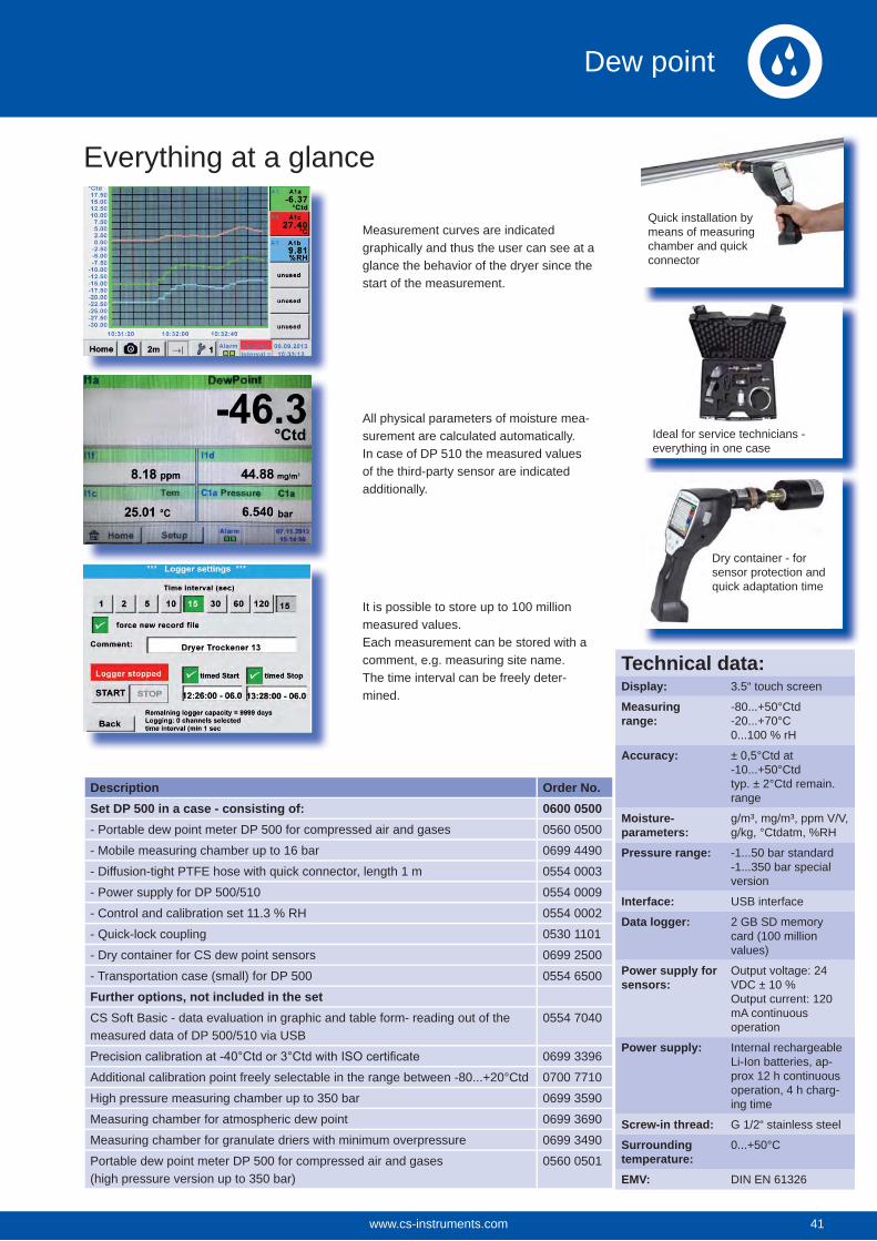
Everything at a glance
Measurement curves are indicated graphically and thus the user can see at a glance the behavior of the dryer since the start of the measurement.
All physical parameters of moisture mea-surement are calculated automatically. In case of DP 510 the measured values of the third-party sensor are indicated additionally.
It is possible to store up to 100 million measured values.Each measurement can be stored with a comment, e.g. measuring site name.The time interval can be freely deter-mined.
Description Order No.Set DP 500 in a case - consisting of: 0600 0500- Portable dew point meter DP 500 for compressed air and gases 0560 0500
- Mobile measuring chamber up to 16 bar 0699 4490
- Diffusion-tight PTFE hose with quick connector, length 1 m 0554 0003
- Power supply for DP 500/510 0554 0009
- Control and calibration set 11.3 % RH 0554 0002
- Quick-lock coupling 0530 1101
- Dry container for CS dew point sensors 0699 2500
- Transportation case (small) for DP 500 0554 6500
Further options, not included in the setCS Soft Basic - data evaluation in graphic and table form- reading out of the measured data of DP 500/510 via USB
0554 7040
0699 3396
Additional calibration point freely selectable in the range between -80...+20°Ctd 0700 7710
High pressure measuring chamber up to 350 bar 0699 3590
Measuring chamber for atmospheric dew point 0699 3690
Measuring chamber for granulate driers with minimum overpressure 0699 3490
Portable dew point meter DP 500 for compressed air and gases (high pressure version up to 350 bar)
0560 0501
Quick installation by means of measuring chamber and quick connector
Ideal for service technicians - everything in one case
Dry container - for sensor protection and quick adaptation time
Technical data:Display: 3.5“ touch screen
Measuring range:
-80...+50°Ctd-20...+70°C0...100 % rH
Accuracy: ± 0,5°Ctd at-10...+50°Ctdtyp. ± 2°Ctd remain.range
Moisture- parameters:
g/m³, mg/m³, ppm V/V, g/kg, °Ctdatm, %RH
Pressure range: -1...50 bar standard-1...350 bar special version
Interface: USB interface
Data logger: 2 GB SD memory card (100 million values)
Power supply for sensors:
Output voltage: 24 VDC ± 10 % Output current: 120 mA continuous operation
Power supply: Internal rechargeable Li-Ion batteries, ap-prox 12 h continuous operation, 4 h charg-ing time
Screw-in thread: G 1/2“ stainless steel
Surrounding temperature:
0...+50°C
EMV: DIN EN 61326
41www.cs-instruments.com 41
Dew point
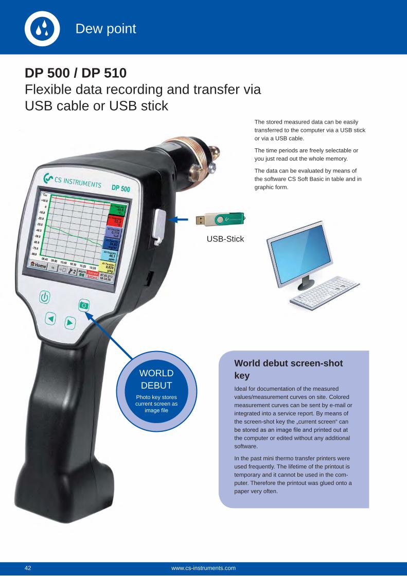
42
DP 500 / DP 510Flexible data recording and transfer via USB cable or USB stick
The stored measured data can be easily transferred to the computer via a USB stick or via a USB cable.
The time periods are freely selectable or you just read out the whole memory.
The data can be evaluated by means of the software CS Soft Basic in table and in graphic form.
USB-Stick
WORLD DEBUT
Photo key stores current screen as
World debut screen-shot keyIdeal for documentation of the measured values/measurement curves on site. Colored measurement curves can be sent by e-mail or integrated into a service report. By means of the screen-shot key the „current screen“ can
the computer or edited without any additional software.
In the past mini thermo transfer printers were used frequently. The lifetime of the printout is temporary and it cannot be used in the com-puter. Therefore the printout was glued onto a paper very often.
www.cs-instruments.com42
Dew point
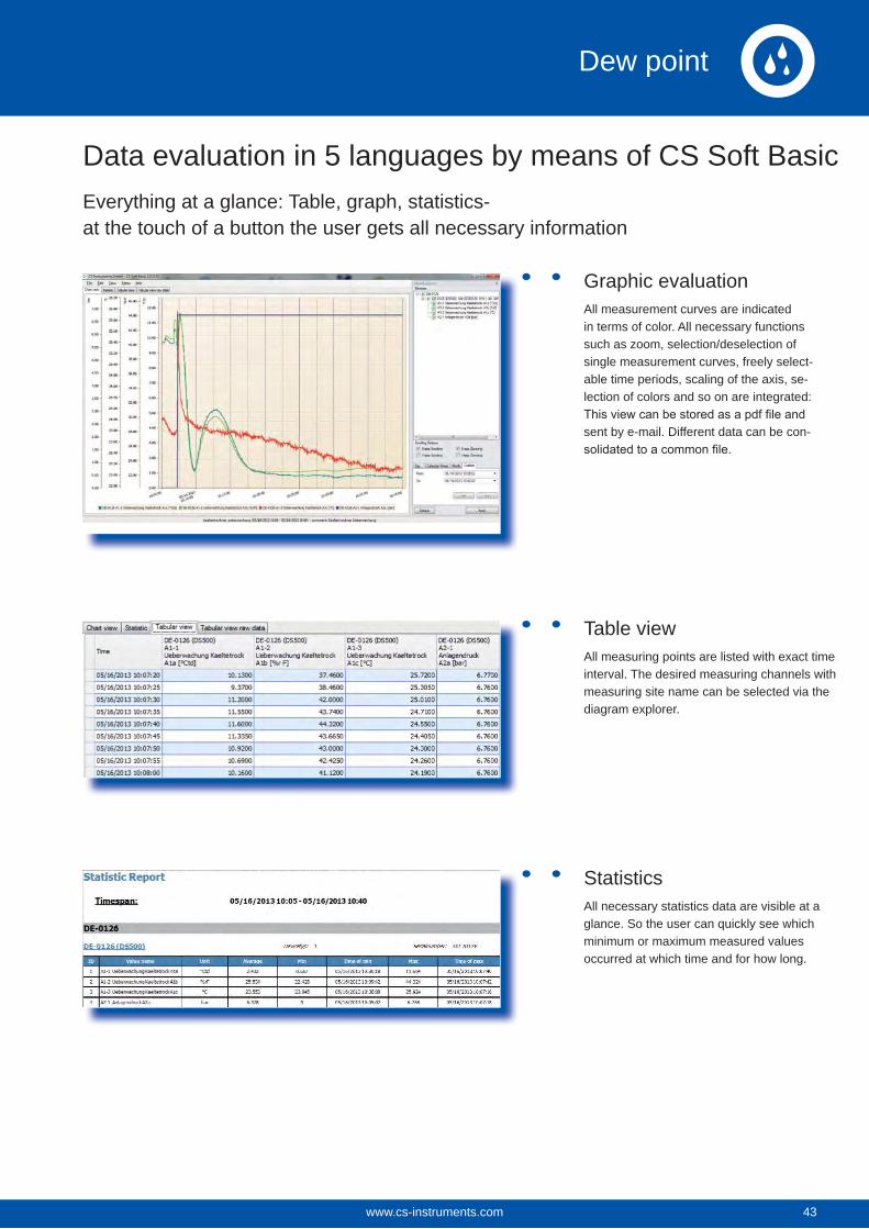
Data evaluation in 5 languages by means of CS Soft BasicEverything at a glance: Table, graph, statistics-at the touch of a button the user gets all necessary information
Graphic evaluationAll measurement curves are indicated in terms of color. All necessary functions such as zoom, selection/deselection of single measurement curves, freely select-able time periods, scaling of the axis, se-lection of colors and so on are integrated:
sent by e-mail. Different data can be con-
Table viewAll measuring points are listed with exact time interval. The desired measuring channels with measuring site name can be selected via the diagram explorer.
StatisticsAll necessary statistics data are visible at a glance. So the user can quickly see which minimum or maximum measured values occurred at which time and for how long.
43www.cs-instruments.com 43
Dew point
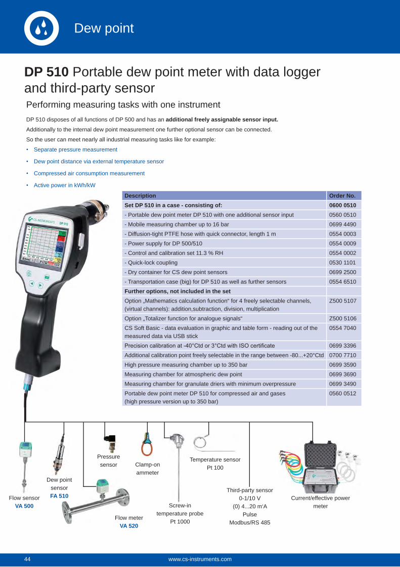
44
DP 510 Portable dew point meter with data logger and third-party sensor
Description Order No.Set DP 510 in a case - consisting of: 0600 0510- Portable dew point meter DP 510 with one additional sensor input 0560 0510
- Mobile measuring chamber up to 16 bar 0699 4490
- Diffusion-tight PTFE hose with quick connector, length 1 m 0554 0003
- Power supply for DP 500/510 0554 0009
- Control and calibration set 11.3 % RH 0554 0002
- Quick-lock coupling 0530 1101
- Dry container for CS dew point sensors 0699 2500
- Transportation case (big) for DP 510 as well as further sensors 0554 6510
Further options, not included in the setOption „Mathematics calculation function“ for 4 freely selectable channels, (virtual channels): addition,subtraction, division, multiplication
Z500 5107
Option „Totalizer function for analogue signals“ Z500 5106
CS Soft Basic - data evaluation in graphic and table form - reading out of the measured data via USB stick
0554 7040
0699 3396
Additional calibration point freely selectable in the range between -80...+20°Ctd 0700 7710
High pressure measuring chamber up to 350 bar 0699 3590
Measuring chamber for atmospheric dew point 0699 3690
Measuring chamber for granulate driers with minimum overpressure 0699 3490
Portable dew point meter DP 510 for compressed air and gases (high pressure version up to 350 bar)
0560 0512
Third-party sensor0-1/10 V
(0) 4...20 m‘APulse
Modbus/RS 485
Dew pointsensorFA 510Flow sensor
VA 500
Flow meterVA 520
Pressure sensor Clamp-on
ammeter
Screw-in temperature probe
Pt 1000
Temperature sensorPt 100
Current/effective power meter
Performing measuring tasks with one instrumentDP 510 disposes of all functions of DP 500 and has an additional freely assignable sensor input.
Additionally to the internal dew point measurement one further optional sensor can be connected.
So the user can meet nearly all industrial measuring tasks like for example:
Separate pressure measurement
Dew point distance via external temperature sensor
Compressed air consumption measurement
Active power in kWh/kW
www.cs-instruments.com44
Dew point
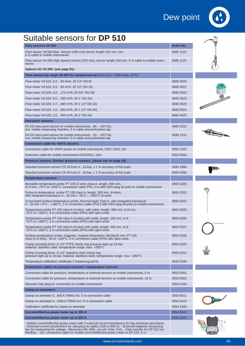
Suitable sensors for DP 510Flow sensors VA 500: Order No.
Flow sensor VA 500 Max. Version (185 m/s) sensor length 220 mm, incl. 5 m cable to mobile instruments
0695 1124
Flow sensor VA 500 High-Speed Version (224 m/s), sensor length 220 mm, 5 m cable to mobile instru-ments
0695 1125
Options for VA 500: (see page 81)
Flow measuring range VA 520 for compressed air:(ISO 1217: 1000 mbar, 20°C)
Flow meter VA 520, 0,8... 90 l/min, (R 1/4“ DN 8) 0695 0520
Flow meter VA 520, 0,2... 90 m³/h, (R 1/2“ DN 15) 0695 0521
Flow meter VA 520, 0,3... 170 m³/h, (R 3/4“ DN 20) 0695 0522
Flow meter VA 520, 0,5... 290 m³/h, (R 1“ DN 25) 0695 0523
Flow meter VA 520, 0,7... 480 m³/h, (R 1 1/4“ DN 32) 0695 0526
Flow meter VA 520, 1,0... 550 m³/h, (R 1 1/2“ DN 40) 0695 0524
Flow meter VA 520, 2,0... 900 m³/h, (R 2“ DN 50) 0695 0525
Dew point sensors:
FA 510 dew point sensor for mobile instruments, -80…+20°Ctd,incl. mobile measuring chamber, 5 m cable and perforated cap
0699 1510
FA 510 dew point sensor for mobile instruments, -20…+50°Ctd, incl. mobile measuring chamber, 5 m cable and perforated cap
0699 1512
Connection cable for VA/FA sensors:
Connection cable for VA/FA series on mobile instruments, ODU / M12, 5m 0553 1503
Extension cable for mobile instruments ODU/ODU, 10m 0553 0504
Pressure sensors: (further pressure sensors, please see on page 24)
Standard pressure sensor CS 16 from 0…16 bar, ± 1 % accuracy of full scale 0694 1886
Standard pressure sensor CS 40 from 0…40 bar, ± 1 % accuracy of full scale 0694 0356
Temperature sensors:
Bendable temperature probe PT 100 (2-wire) class A, length: 300 mm,d=3 mm, -70°C to +500°C, connection cable PFA, 2 m with ODU-plug (8 pole) to mobile instruments
0604 0200
Screw-in temperature probe PT 100 class A, length: 300 mm, d=6mm,with integrated transducer 4…20 mA = -50°C…+500°C (2-wire)
0604 0201
Cross-band surface temperature probe, thermocouple Type K, with integrated transducer 4…20 mA = 0°C…+180°C, 2 m connection calbe (PVC) with ODU-plug (8-pole) to mobile instruments
0604 0202
Temperature probe PT 100 class A (4-wire) with cable, length: 300 mm, d=6 mm,-70°C to +260°C, 5 m connection cable (PFA) with open ends
0604 0205
Temperature probe PT 100 class A (4-wire) with cable, length: 100 mm, d=6-70°C to +260°C, 5 m connection cable (PFA) with open ends
0604 0206
Temperature probe PT 100 class A (4-wire) with cable, length: 200 mm, d=6-70°C to +260°C, 5 m connection cable (PFA) with open ends
0604 0207
Surface temperature probe, magnetic, magnet dimensions 39x26x25 mm, PT 100class B (2-wire), -30 to +180°C, 5 m connection cable (PFA) with open ends
0604 0208
Clamp screwing 6mm; G 1/2“ PTFE clamp ring pressure tight up 10 barmaterial: stainless steel, temperature range: max. +260°C
0554 0200
Clamp screwing 6mm; G 1/2“ stainless steel clamp ringpressure tight up to 16 bar, material: stainless steel, temperature range: max. +260°C
0554 0201
0520 0180
Connection cables for pressure sensors / temperature sensors:
Connection cable for pressure, temperature or external sensors on mobile instruments, 5 m 0553 0501
Connection cable for pressure, temperature or external sensors on mobile instruments, 10 m 0553 0502
Mounted Odu plug for connection on mobile instruments Z604 0104
Clamp-on ammeters:
Clamp-on ammeter 0...400 A TRMS incl. 5 m connection cable 0554 0511
Clamp-on ammeter 0...1000 A TRMS incl. 5 m connection cable 0554 0519
0554 3333
Current/effective power meter up to 100 A 0554 5341
Current/effective power meter up to 600 A 0554 5342
- Mobile current/effective power meter with 3 external current transducers for big machines and plants, - External current transformers for clamping on cables (100 or 600 A), - External magnetic measuring tips for measuring the voltage, -Measures kW, kWh, cos phi, kVar, KVA, - Data transfer for DP 510 via Modbus, - incl. connection cable for mobile current/effective power meter to DP 510, 5 m
45www.cs-instruments.com 45
Dew point
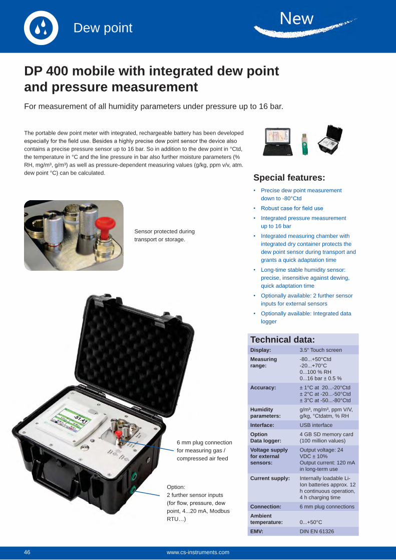
46
DP 400 mobile with integrated dew point and pressure measurementFor measurement of all humidity parameters under pressure up to 16 bar.
The portable dew point meter with integrated, rechargeable battery has been developed
contains a precise pressure sensor up to 16 bar. So in addition to the dew point in °Ctd, the temperature in °C and the line pressure in bar also further moisture parameters (% RH, mg/m³, g/m³) as well as pressure-dependent measuring values (g/kg, ppm v/v, atm. dew point °C) can be calculated. Special features:
Precise dew point measurement down to -80°Ctd
Integrated pressure measurement up to 16 bar
Integrated measuring chamber with integrated dry container protects the dew point sensor during transport and grants a quick adaptation time
Long-time stable humidity sensor: precise, insensitive against dewing, quick adaptation time
Optionally available: 2 further sensor inputs for external sensors
Optionally available: Integrated data logger
Sensor protected during transport or storage.
Technical data:Display: 3.5“ Touch screen
Measuring range:
-80...+50°Ctd-20...+70°C0...100 % RH0...16 bar ± 0.5 %
Accuracy: ± 1°C at 20...-20°Ctd± 2°C at -20...-50°Ctd± 3°C at -50...-80°Ctd
Humidity parameters:
g/m³, mg/m³, ppm V/V, g/kg, °Ctdatm, % RH
Interface: USB interface
OptionData logger:
4 GB SD memory card(100 million values)
Voltage supply for external sensors:
Output voltage: 24VDC ± 10% Output current: 120 mA in long-term use
Current supply: Internally loadable Li-Ion batteries approx. 12 h continuous operation, 4 h charging time
Connection: 6 mm plug connections
Ambient temperature: 0...+50°C
EMV: DIN EN 61326
6 mm plug connection for measuring gas / compressed air feed
Option:2 further sensor inputs
point, 4...20 mA, Modbus RTU…)
www.cs-instruments.com46
Dew point
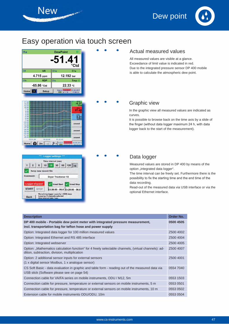
Description Order No.DP 400 mobile - Portable dew point meter with integrated pressure measurement, 0500 4505
Option: Integrated data logger for 100 million measured values Z500 4002
Option: Integrated Ethernet and RS 485 interface Z500 4004
Option: Integrated webserver Z500 4005
Option: „Mathematics calculation function“ for 4 freely selectable channels, (virtual channels): ad-dition, subtraction, division, multiplication
Z500 4007
Option: 2 additional sensor inputs for external sensors (1 x digital sensor Modbus, 1 x analogue sensor)
Z500 4001
CS Soft Basic - data evaluation in graphic and table form - reading out of the measured data via USB stick (Software please see on page 54)
0554 7040
Connection cable for VA/FA series on mobile instruments, ODU / M12, 5m 0553 1503
Connection cable for pressure, temperature or external sensors on mobile instruments, 5 m 0553 0501
Connection cable for pressure, temperature or external sensors on mobile instruments, 10 m 0553 0502
Extension cable for mobile instruments ODU/ODU, 10m 0553 0504
Actual measured valuesAll measured values are visible at a glance. Exceedance of limit value is indicated in red.Due to the integrated pressure sensor DP 400 mobileis able to calculate the atmospheric dew point.
Graphic viewIn the graphic view all measured values are indicated as curves.It is possible to browse back on the time axis by a slide of
logger back to the start of the measurement).
Data loggerMeasured values are stored in DP 400 by means of the option „integrated data logger“. The time interval can be freely set. Furthermore there is the
data recording. Read-out of the measured data via USB interface or via the optional Ethernet interface.
Easy operation via touch screen
47www.cs-instruments.com 47
Dew point
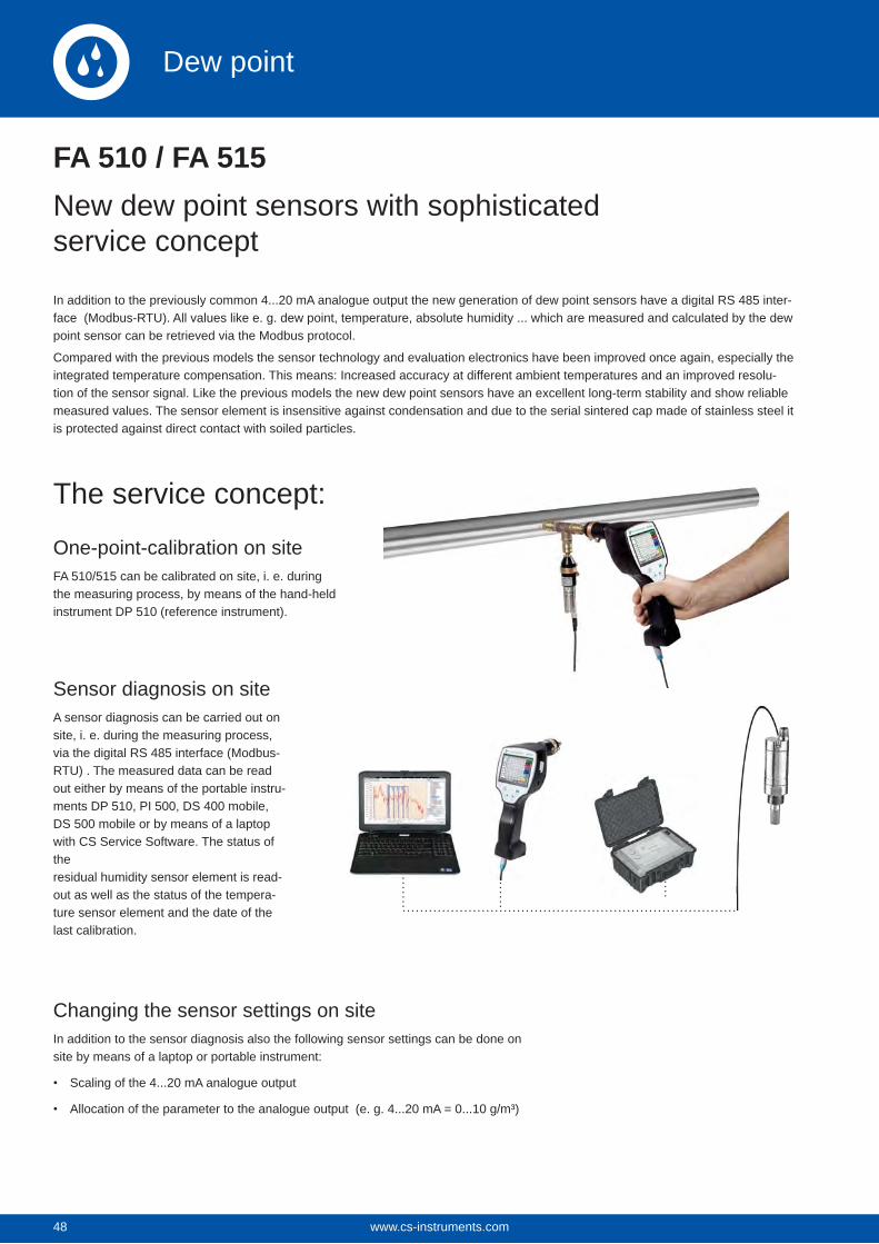
48
FA 510 / FA 515New dew point sensors with sophisticated service concept
In addition to the previously common 4...20 mA analogue output the new generation of dew point sensors have a digital RS 485 inter-face (Modbus-RTU). All values like e. g. dew point, temperature, absolute humidity ... which are measured and calculated by the dew point sensor can be retrieved via the Modbus protocol.
Compared with the previous models the sensor technology and evaluation electronics have been improved once again, especially the integrated temperature compensation. This means: Increased accuracy at different ambient temperatures and an improved resolu-tion of the sensor signal. Like the previous models the new dew point sensors have an excellent long-term stability and show reliable measured values. The sensor element is insensitive against condensation and due to the serial sintered cap made of stainless steel it is protected against direct contact with soiled particles.
One-point-calibration on siteFA 510/515 can be calibrated on site, i. e. during the measuring process, by means of the hand-held instrument DP 510 (reference instrument).
The service concept:
Sensor diagnosis on siteA sensor diagnosis can be carried out on site, i. e. during the measuring process, via the digital RS 485 interface (Modbus-RTU) . The measured data can be read out either by means of the portable instru-ments DP 510, PI 500, DS 400 mobile, DS 500 mobile or by means of a laptop with CS Service Software. The status of the residual humidity sensor element is read-out as well as the status of the tempera-ture sensor element and the date of the last calibration.
Changing the sensor settings on siteIn addition to the sensor diagnosis also the following sensor settings can be done on site by means of a laptop or portable instrument:
Scaling of the 4...20 mA analogue output
Allocation of the parameter to the analogue output (e. g. 4...20 mA = 0...10 g/m³)
www.cs-instruments.com48
Dew point
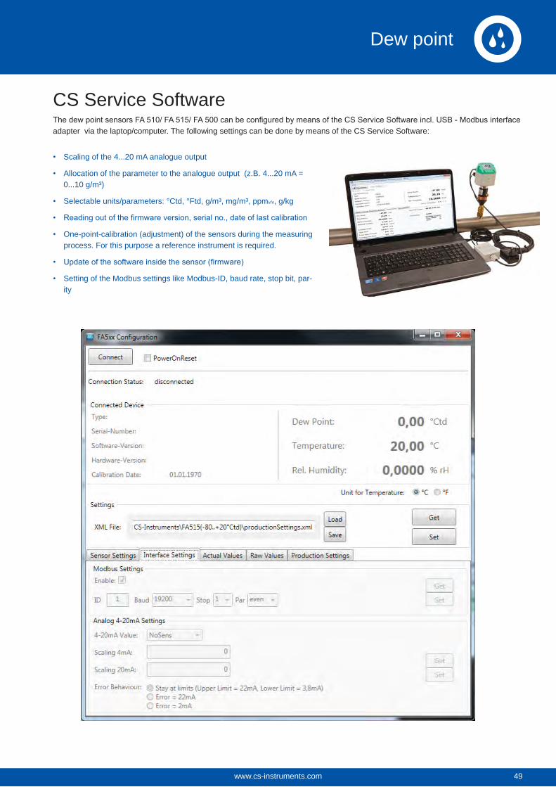
CS Service Softwareadapter via the laptop/computer. The following settings can be done by means of the CS Service Software:
Scaling of the 4...20 mA analogue output
Allocation of the parameter to the analogue output (z.B. 4...20 mA = 0...10 g/m³)
Selectable units/parameters: °Ctd, °Ftd, g/m³, mg/m³, ppmv/v, g/kg
One-point-calibration (adjustment) of the sensors during the measuring process. For this purpose a reference instrument is required.
Setting of the Modbus settings like Modbus-ID, baud rate, stop bit, par-ity
49www.cs-instruments.com 49
Dew point
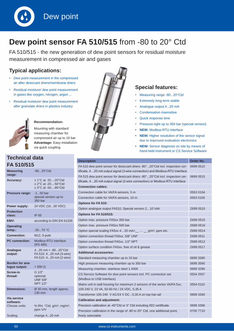
50
Special features:Measuring range -80...20°Ctd
Extremely long-term stable
Analogue output 4...20 mA
Condensation insensitive
Quick response time
Pressure-tight up to 350 bar (special version)
NEW: Modbus-RTU interface
NEW: Higher resolution of the sensor signal due to improved evaluation electronics
NEW: Sensor diagnosis on site by means of hand-held instrument or CS Service Software
Description Order No.FA 510 dew point sensor for desiccant driers -80°...20°Ctd incl. inspection cer- 0699 0510
FA 515 dew point sensor for desiccant driers -80°...20°Ctd incl. inspection cer- 0699 0515
Connection cables:
Connection cable for VA/FA sensors, 5 m 0553 0104
Connection cable for VA/FA sensors, 10 m 0553 0105
Options for FA 510:Option analogue output FA510, Special version 2…10 Volt Z699 0510
Options for FA 510/515:
Option max. pressure FA5xx 350 bar Z699 0515
Option max. pressure FA5xx 500 bar Z699 0516
Option special scaling FA5xx 4…20 mA=__ … __ g/m³, ppm etc. Z699 0514
Option connection thread FA5xx, 5/8” UNF Z699 0511
Option connection thread FA5xx, 1/2“ NPT Z699 0512
Option surface condition FA5xx, free of oil & grease Z699 0517
Additional accessories:Standard measuring chamber up to 16 bar 0699 3390
High pressure measuring chamber up to 350 bar 0699 3590
Measuring chamber, stainless steel 1.4305 0699 3290
CS Service Software for dew point sensors incl. PC connection set (Modbus to USB Interface)
0554 2007
Mains unit in wall housing for maximum 2 sensors of the series VA/FA 5xx,100-240 V, 23 VA, 50-60 Hz / 24 VDC, 0.35 A
0554 0110
Transformer 100-240 V AC/24 V DC , 0,35 A on top-hat rail 0699 3340
Calibration and adjustment:0699 3396
Precision calibration in the range of -80 to 20° Ctd, one additional point, freely selectable
0700 7710
Dew point sensor FA 510/515 from -80 to 20° CtdFA 510/515 - the new generation of dew point sensors for residual moisture measurement in compressed air and gases
Typical applications:Dew point measurement in the compressed air after desiccant driers/membrane driers
Residual moisture/ dew point measurement in gases like oxygen, nitrogen, argon ...
Residual moisture/ dew point measurement after granulate driers in plastics industry
Recommendation:
Mounting with standard measuring chamber for compressed air up to 16 barAdvantage: Easy installation via quick coupling
Technical dataFA 510/515Measuring range:
-80...20°Ctd
Accuracy: ± 1°C at 20...-20°Ctd± 2°C at -20...-50°Ctd± 3°C at -50...-80°Ctd
Pressure range: -1...50 barspecial version up to350 bar
Power supply: 24 VDC (16...30 VDC)
Protection class: IP 65
EMV: according to DIN EN 61326
Operating temp.: -20...70 °C
Connection: M12, 5-pole
PC connection: Modbus-RTU interface (RS 485)
Analogue output:
4...20 mA = -80...20°Ctd FA 510: 4...20 mA (3-wire)FA 515: 4...20 mA (2-wire)
Burden for ana-logue output:Screw-in thread:
G 1/2“optional:UNF 5/8“NPT 1/2“
Dimensions: Ø 30 mm, length approx. 130 mm
Via service software:Choose units:
Scaling:
% RH, °Ctd, g/m³, mg/m³, ppm V/V
change 4...20 mA
www.cs-instruments.com50
Dew point
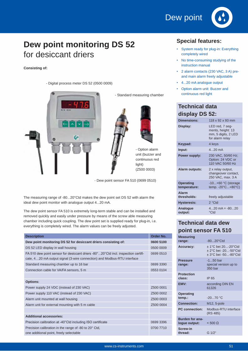
Description Order No.Dew point monitoring DS 52 for desiccant driers consisting of: 0600 5100DS 52 LED display in wall housing 0500 0009
-cate, 4…20 mA output signal (3-wire connection) and Modbus-RTU interface
0699 0510
Standard measuring chamber up to 16 bar 0699 3390
Connection cable for VA/FA sensors, 5 m 0553 0104
Options:Power supply 24 VDC (instead of 230 VAC) Z500 0001
Power supply 110 VAC (instead of 230 VAC) Z500 0002
Alarm unit mounted at wall housing Z500 0003
Alarm unit for external mounting with 5 m cable Z500 0004
Additional accessories:0699 3396
Precision calibration in the range of -80 to 20° Ctd, one additional point, freely selectable
0700 7710
Special features:System ready for plug-in: Everything completely wired
No time-consuming studying of the instruction manual
2 alarm contacts (230 VAC, 3 A) pre- and main alarm freely adjustable
4...20 mA analogue output
Option alarm unit: Buzzer and continuous red light
Consisting of:
The measuring range of -80...20°Ctd makes the dew point set DS 52 with alarm the ideal dew point monitor with analogue output 4...20 mA.
The dew point sensor FA 510 is extremely long-term stable and can be installed and removed quickly and easily under pressure by means of the screw able measuring chamber including quick coupling. The dew point set is supplied ready for plug-in, i.e. everything is completely wired. The alarm values can be freely adjusted.
- Standard measuring chamber
- Dew point sensor FA 510 (0699 0510)
- Option alarm unit (buzzer and continuous red light)(Z500 0003)
- Digital process meter DS 52 (0500 0009)
Dew point monitoring DS 52 for desiccant driers
Technical data display DS 52:Dimensions: 118 x 92 x 93 mm
Display: LED red, 7 seg-ments, height: 13 mm, 5 digits, 2 LED for alarm relay
Keypad: 4 keys
Input: 4...20 mA
Power supply: 230 VAC, 50/60 Hz; Option: 24 VDC or 110 VAC 50/60 Hz
Alarm outputs: 2 x relay output, changeover contact, 250 VAC, max. 3 A
Operating temperature:
-10...+60 °C (storage temp. -20°C...+80°C)
Alarmthresholds: freely adjustable
Hysteresis: 2 °Ctd
Analogue output:
4...20 mA = -80...20 °Ctd
Technical data dew point sensor FA 510Measuring range: -80...20°Ctd
Accuracy: ± 1°C bei 20...-20°Ctd± 2°C bei -20...-50°Ctd± 3°C bei -50...-80°Ctd
Pressure range:
-1...50 barspecial version up to 350 bar
Protection class: IP 65
EMV: according DIN EN 61326
Operating temp.: -20...70 °C
Connection: M12, 5-pole
PC connection: Modbus-RTU interface (RS 485)
Burden for ana-logue output:Screw-in thread: G 1/2“
51www.cs-instruments.com 51
Dew point
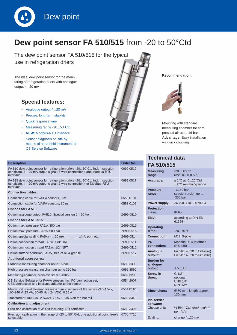
52
Recommendation:The ideal dew point sensor for the moni-toring of refrigeration driers with analogue output 4...20 mA
Mounting with standard measuring chamber for com-pressed air up to 16 barAdvantage: Easy installation via quick coupling
Description Order No.FA 510 dew point sensor for refrigeration driers -20...50°Ctd incl. inspection
interface
0699 0512
FA 515 dew point sensor for refrigeration driers -20...50°Ctd incl. inspection
interface
0699 0517
Connection cables:
Connection cable for VA/FA sensors, 5 m 0553 0104
Connection cable for VA/FA sensors, 10 m 0553 0105
Options for FA 510:Option analogue output FA510, Special version 2…20 Volt Z699 0510
Options for FA 510/515:Option max. pressure FA5xx 350 bar Z699 0515
Option max. pressure FA5xx 500 bar Z699 0516
Option special scaling FA5xx 4…20 mA=__ … __ g/m³, ppm etc. Z699 0514
Option connection thread FA5xx, 5/8“ UNF Z699 0511
Option connection thread FA5xx, 1/2“ NPT Z699 0512
Option surface condition FA5xx, free of oil & grease Z699 0517
Additional accessories:Standard measuring chamber up to 16 bar 0699 3390
High pressure measuring chamber up to 350 bar 0699 3590
Measuring chamber, stainless steel 1.4305 0699 3290
CS Service Software for FA/VA sensors incl. PC connection set, USB connection and interface adapter to the sensor
0554 2007
Mains unit in wall housing for maximum 2 sensors of the series VA/FA 5xx,100-240 V, 23 VA, 50-60 Hz / 24 VDC, 0.35 A
0554 0110
Transformer 100-240 V AC/24 V DC , 0,35 A on top-hat rail 0699 3340
Calibration and adjustment:0699 3396
Precision calibration in the range of -20 to 50° Ctd, one additional point, freely selectable
0700 7710
Dew point sensor FA 510/515 from -20 to 50°CtdThe dew point sensor FA 510/515 for the typical use in refrigeration driers
Special features:Analogue output 4...20 mA
Precise, long-term stability
Quick response time
Measuring range -20...50°Ctd
NEW: Modbus-RTU interface
Sensor diagnosis on site by means of hand-held instrument or CS Service Software
Technical dataFA 510/515Measuring range:
-20...50°Ctdresp. 0...100% rF
Accuracy: ± 1°C at 0...20°Ctd± 2°C remaining range
Pressure range:
-1...50 barspecial version up to 350 bar
Power supply: 24 VDC (10...30 VDC)
Protection class: IP 65
EMV: according to DIN EN 61326
Operating temp.: -20...70 °C
Connection: M12, 5-pole
PC connection:
Modbus-RTU interface (RS 485)
Analogue output:
FA 510: 4...20 mA (3-wire)FA 515: 4...20 mA (2-wire)
Burden for analogue output:Screw-in thread:
G 1/2“optional:UNF 5/8“NPT 1/2“
Dimensions: Ø 30 mm, length approx. 130 mm
Via service software:Choose units:
Scaling:
% RH, °Ctd, g/m³, mg/m³, ppm V/V
change 4...20 mA
www.cs-instruments.com52
Dew point
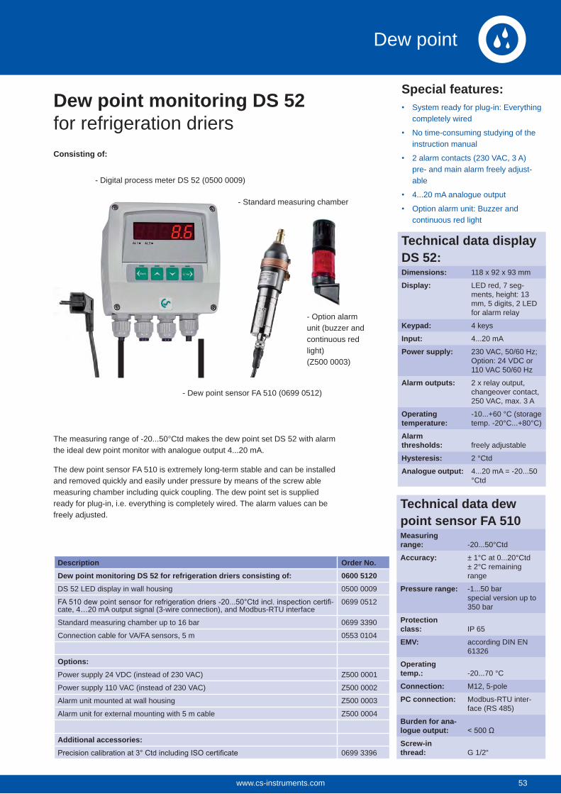
Description Order No.Dew point monitoring DS 52 for refrigeration driers consisting of: 0600 5120DS 52 LED display in wall housing 0500 0009
-cate, 4…20 mA output signal (3-wire connection), and Modbus-RTU interface
0699 0512
Standard measuring chamber up to 16 bar 0699 3390
Connection cable for VA/FA sensors, 5 m 0553 0104
Options:Power supply 24 VDC (instead of 230 VAC) Z500 0001
Power supply 110 VAC (instead of 230 VAC) Z500 0002
Alarm unit mounted at wall housing Z500 0003
Alarm unit for external mounting with 5 m cable Z500 0004
Additional accessories:0699 3396
Special features:System ready for plug-in: Everything completely wired
No time-consuming studying of the instruction manual
2 alarm contacts (230 VAC, 3 A) pre- and main alarm freely adjust-able
4...20 mA analogue output
Option alarm unit: Buzzer and continuous red light
Consisting of:
The measuring range of -20...50°Ctd makes the dew point set DS 52 with alarm the ideal dew point monitor with analogue output 4...20 mA.
The dew point sensor FA 510 is extremely long-term stable and can be installed and removed quickly and easily under pressure by means of the screw able measuring chamber including quick coupling. The dew point set is supplied ready for plug-in, i.e. everything is completely wired. The alarm values can be freely adjusted.
- Standard measuring chamber
Dew point monitoring DS 52 for refrigeration driers
- Dew point sensor FA 510 (0699 0512)
- Digital process meter DS 52 (0500 0009)
- Option alarm unit (buzzer and continuous red light)(Z500 0003)
Technical data display DS 52:Dimensions: 118 x 92 x 93 mm
Display: LED red, 7 seg-ments, height: 13 mm, 5 digits, 2 LED for alarm relay
Keypad: 4 keys
Input: 4...20 mA
Power supply: 230 VAC, 50/60 Hz; Option: 24 VDC or 110 VAC 50/60 Hz
Alarm outputs: 2 x relay output, changeover contact, 250 VAC, max. 3 A
Operating temperature:
-10...+60 °C (storage temp. -20°C...+80°C)
Alarmthresholds: freely adjustable
Hysteresis: 2 °Ctd
Analogue output: 4...20 mA = -20...50 °Ctd
Technical data dew point sensor FA 510Measuring range: -20...50°Ctd
Accuracy: ± 1°C at 0...20°Ctd± 2°C remaining range
Pressure range: -1...50 barspecial version up to 350 bar
Protection class: IP 65
EMV: according DIN EN 61326
Operating temp.: -20...70 °C
Connection: M12, 5-pole
PC connection: Modbus-RTU inter-face (RS 485)
Burden for ana-logue output:Screw-in thread: G 1/2“
53www.cs-instruments.com 53
Dew point
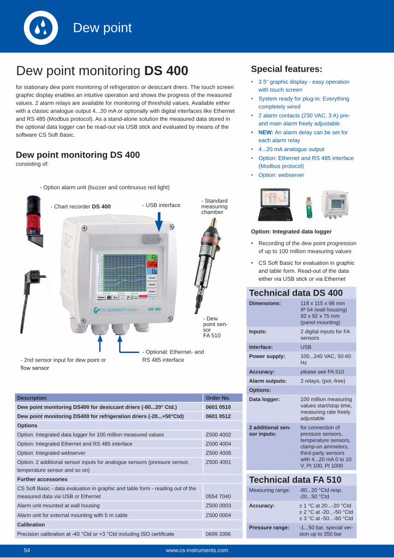
54
for stationary dew point monitoring of refrigeration or desiccant driers. The touch screen graphic display enables an intuitive operation and shows the progress of the measured values. 2 alarm relays are available for monitoring of threshold values. Available either with a classic analogue output 4...20 mA or optionally with digital interfaces like Ethernet and RS 485 (Modbus protocol). As a stand-alone solution the measured data stored in the optional data logger can be read-out via USB stick and evaluated by means of the software CS Soft Basic.
Special features:3.5“ graphic display - easy operation with touch screenSystem ready for plug-in: Everything completely wired2 alarm contacts (230 VAC, 3 A) pre- and main alarm freely adjustableNEW: An alarm delay can be set for each alarm relay4...20 mA analogue outputOption: Ethernet and RS 485 interface (Modbus protocol)Option: webserver
Description Order No.Dew point monitoring DS400 for desiccant driers (-80...20° Ctd.) 0601 0510Dew point monitoring DS400 for refrigeration driers (-20...+50°Ctd) 0601 0512OptionsOption: Integrated data logger for 100 million measured values Z500 4002
Option: Integrated Ethernet and RS 485 interface Z500 4004
Option: Integrated webserver Z500 4005
Option: 2 additional sensor inputs for analogue sensors (pressure sensor, temperature sensor and so on)
Z500 4001
Further accessoriesCS Soft Basic - data evaluation in graphic and table form - reading out of the measured data via USB or Ethernet 0554 7040
Alarm unit mounted at wall housing Z500 0003
Alarm unit for external mounting with 5 m cable Z500 0004
Calibration
0699 3396
- Standard measuring chamber
- Optional: Ethernet- and RS 485 interface
- Option alarm unit (buzzer and continuous red light)
- 2nd sensor input for dew point or
- USB interface- Chart recorder DS 400
Dew point monitoring DS 400consisting of:
- Dew point sen-sor FA 510
Option: Integrated data logger
Recording of the dew point progression of up to 100 million measuring values
CS Soft Basic for evaluation in graphic and table form. Read-out of the data either via USB stick or via Ethernet
Dew point monitoring DS 400
Technical data DS 400Dimensions: 118 x 115 x 98 mm
IP 54 (wall housing)92 x 92 x 75 mm(panel mounting)
Inputs: 2 digital inputs for FA sensors
Interface: USB
Power supply: 100...240 VAC, 50-60 Hz
Accuracy: please see FA 510
Alarm outputs: 2 relays, (pot.-free)
Options:Data logger: 100 million measuring
values start/stop time, measuring rate freely adjustable
2 additional sen-sor inputs:
for connection of pressure sensors, temperature sensors, clamp-on ammeters, third-party sensors with 4...20 mA 0 to 10 V, Pt 100, Pt 1000
Technical data FA 510Measuring range: -80...20 °Ctd resp.
-20...50 °Ctd
Accuracy: ± 1 °C at 20...-20 °Ctd± 2 °C at -20...-50 °Ctd± 3 °C at -50...-80 °Ctd
Pressure range: -1...50 bar, special ver-sion up to 350 bar
www.cs-instruments.com54
Dew point
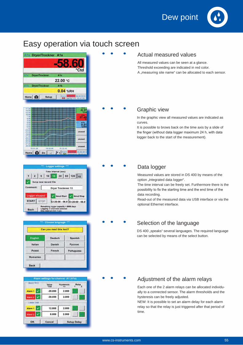
Actual measured valuesAll measured values can be seen at a glance.Threshold exceeding are indicated in red color.A „measuring site name“ can be allocated to each sensor.
Graphic viewIn the graphic view all measured values are indicated as curves.It is possible to brows back on the time axis by a slide of
logger back to the start of the measurement).
Data loggerMeasured values are stored in DS 400 by means of the option „integrated data logger“. The time interval can be freely set. Furthermore there is the
data recording. Read-out of the measured data via USB interface or via the optional Ethernet interface.
Selection of the languageDS 400 „speaks“ several languages. The required language can be selected by means of the select button.
Adjustment of the alarm relaysEach one of the 2 alarm relays can be allocated individu-ally to a connected sensor. The alarm thresholds and the hysteresis can be freely adjusted.NEW: It is possible to set an alarm delay for each alarm relay so that the relay is just triggered after that period of time.
Easy operation via touch screen
55www.cs-instruments.com 55
Dew point
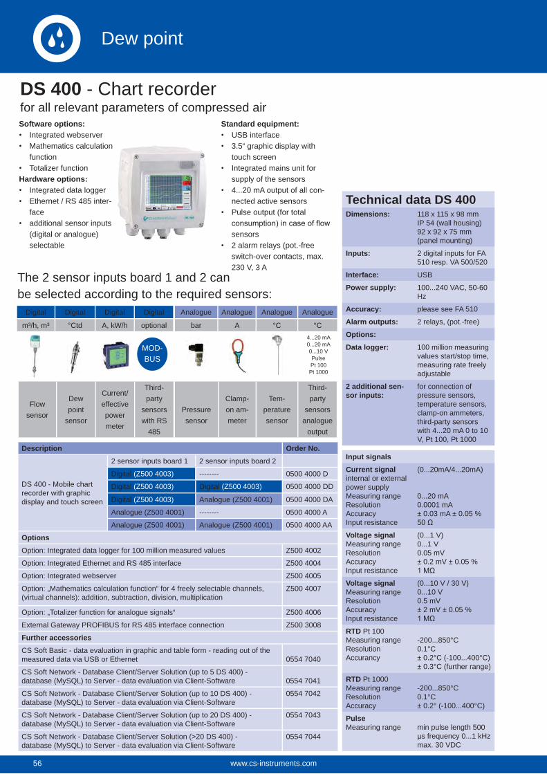
56
Software options:Integrated webserverMathematics calculation functionTotalizer function
Hardware options:Integrated data loggerEthernet / RS 485 inter-faceadditional sensor inputs (digital or analogue) selectable
Standard equipment:USB interface3.5“ graphic display with touch screenIntegrated mains unit for supply of the sensors4...20 mA output of all con-nected active sensorsPulse output (for total
sensors2 alarm relays (pot.-free switch-over contacts, max. 230 V, 3 A
Description Order No.
DS 400 - Mobile chart recorder with graphic display and touch screen
2 sensor inputs board 1 2 sensor inputs board 2
Digital (Z500 4003) -------- 0500 4000 D
Digital (Z500 4003) Digital (Z500 4003) 0500 4000 DD
Digital (Z500 4003) Analogue (Z500 4001) 0500 4000 DA
Analogue (Z500 4001) -------- 0500 4000 A
Analogue (Z500 4001) Analogue (Z500 4001) 0500 4000 AA
OptionsOption: Integrated data logger for 100 million measured values Z500 4002
Option: Integrated Ethernet and RS 485 interface Z500 4004
Option: Integrated webserver Z500 4005
Option: „Mathematics calculation function“ for 4 freely selectable channels, (virtual channels): addition, subtraction, division, multiplication
Z500 4007
Option: „Totalizer function for analogue signals“ Z500 4006
External Gateway PROFIBUS for RS 485 interface connection Z500 3008
Further accessoriesCS Soft Basic - data evaluation in graphic and table form - reading out of the measured data via USB or Ethernet 0554 7040
CS Soft Network - Database Client/Server Solution (up to 5 DS 400) - database (MySQL) to Server - data evaluation via Client-Software 0554 7041
CS Soft Network - Database Client/Server Solution (up to 10 DS 400) - database (MySQL) to Server - data evaluation via Client-Software
0554 7042
CS Soft Network - Database Client/Server Solution (up to 20 DS 400) - database (MySQL) to Server - data evaluation via Client-Software
0554 7043
CS Soft Network - Database Client/Server Solution (>20 DS 400) - database (MySQL) to Server - data evaluation via Client-Software
0554 7044
Digital Digital Digital Digital
m³/h, m³ °Ctd A, kW/h optional
Flow sensor
Dew point
sensor
Current/effective power meter
Third- party
sensors with RS
485
Analogue Analogue Analogue Analogue
bar A °C °C
Pressure sensor
Clamp- on am-meter
Tem-perature sensor
Third-party
sensors analogue
output
4...20 mA 0...20 mA0...10 VPulsePt 100Pt 1000
DS 400 - Chart recorderfor all relevant parameters of compressed air
MOD-BUS
The 2 sensor inputs board 1 and 2 canbe selected according to the required sensors:
Input signalsCurrent signalinternal or external power supplyMeasuring rangeResolutionAccuracyInput resistance
(0...20mA/4...20mA)
0...20 mA0.0001 mA± 0.03 mA ± 0.05 %
Voltage signalMeasuring rangeResolutionAccuracyInput resistance
(0...1 V)0...1 V0.05 mV± 0.2 mV ± 0.05 %
Voltage signalMeasuring rangeResolutionAccuracyInput resistance
(0...10 V / 30 V)0...10 V0.5 mV± 2 mV ± 0.05 %
RTD Pt 100Measuring rangeResolutionAccurancy
-200...850°C0.1°C± 0.2°C (-100...400°C)± 0.3°C (further range)
RTD Pt 1000Measuring rangeResolutionAccuracy
-200...850°C0.1°C± 0.2° (-100...400°C)
PulseMeasuring range min pulse length 500
μs frequency 0...1 kHzmax. 30 VDC
Technical data DS 400Dimensions: 118 x 115 x 98 mm
IP 54 (wall housing)92 x 92 x 75 mm(panel mounting)
Inputs: 2 digital inputs for FA 510 resp. VA 500/520
Interface: USB
Power supply: 100...240 VAC, 50-60 Hz
Accuracy: please see FA 510
Alarm outputs: 2 relays, (pot.-free)
Options:Data logger: 100 million measuring
values start/stop time, measuring rate freely adjustable
2 additional sen-sor inputs:
for connection of pressure sensors, temperature sensors, clamp-on ammeters, third-party sensors with 4...20 mA 0 to 10 V, Pt 100, Pt 1000
www.cs-instruments.com56
Dew point
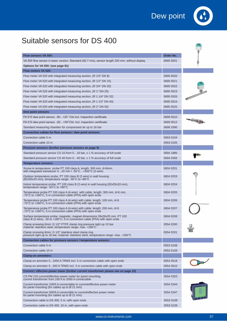
Suitable sensors for DS 400
Flow sensors VA 500: Order No.
0695 5001
Options for VA 500: (see page 81)Flow meters VA 520:
Flow meter VA 520 with integrated measuring section, (R 1/4“ DN 8) 0695 0520
Flow meter VA 520 with integrated measuring section, (R 1/2“ DN 15) 0695 0521
Flow meter VA 520 with integrated measuring section, (R 3/4“ DN 20) 0695 0522
Flow meter VA 520 with integrated measuring section, (R 1“ DN 25) 0695 0523
Flow meter VA 520 with integrated measuring section, (R 1 1/4“ DN 32) 0695 0526
Flow meter VA 520 with integrated measuring section, (R 1 1/2“ DN 40) 0695 0524
Flow meter VA 520 with integrated measuring section, (R 2“ DN 50) 0695 0525
Dew point sensors:
0699 0510
0699 0512
Standard measuring chamber for compressed air up to 16 bar 0699 3390
Connection cable 5 m 0553 0104
Connection cable 10 m 0553 0105
Pressure sensors: (further pressure sensors on page 9)
Standard pressure sensor CS 16 from 0…16 bar, ± 1 % accuracy of full scale 0694 1886
Standard pressure sensor CS 40 from 0…40 bar, ± 1 % accuracy of full scale 0694 0356
Temperature sensors:
Screw-in temperature probe PT 100 class A, length: 300 mm, d=6mm,with integrated transducer 4…20 mA = -50°C…+500°C (2-wire)
0604 0201
Outdoor temperature probe, PT 100 class B (2-wire) in wall housing(82x55x33 mm), temperature range: -50°C to +80°C
0604 0203
Indoor temperature probe, PT 100 class B (2-wire) in wall housing (82x55x33 mm),temperature range: -50°C to +80°C
0604 0204
Temperature probe PT 100 class A (4-wire) with cable, length: 300 mm, d=6 mm,-70°C to +260°C, 5 m connection cable (PFA) with open ends
0604 0205
Temperature probe PT 100 class A (4-wire) with cable, length: 100 mm, d=6-70°C to +260°C, 5 m connection cable (PFA) with open ends
0604 0206
Temperature probe PT 100 class A (4-wire) with cable, length: 200 mm, d=6-70°C to +260°C, 5 m connection cable (PFA) with open ends
0604 0207
Surface temperature probe, magnetic, magnet dimensions 39x26x25 mm, PT 100class B (2-wire), -30 to +180°C, 5 m connection cable (PFA) with open ends
0604 0208
Clamp screwing 6mm; G 1/2“ PTFE clamp ring pressure tight up 10 barmaterial: stainless steel, temperature range: max. +260°C
0554 0200
Clamp screwing 6mm; G 1/2“ stainless steel clamp ringpressure tight up to 16 bar, material: stainless steel, temperature range: max. +260°C
0554 0201
Connection cables for pressure sensors / temperature sensors:
Connection cable 5 m 0553 0108
Connection cable 10 m 0553 0109
Clamp-on ammeters:
Clamp-on ammeter 0...1000 A TRMS incl. 5 m connection cable with open ends 0554 0518
Clamp-on ammeter 0...400 A TRMS incl. 3 m connection cable with open ends 0554 0510
Current / effective power meter (further current transformer please see on page 10)
CS PM 210 current/effective power meter for panel mounting, current transformer from 100 A to 2000 A connectable
0554 5353
Current transformer 100/5 A connectable to current/effective power meter for panel mounting (for cables up to Ø 21 mm)
0554 5344
Current transformer 500/5 A connectible to current/effective power meter for panel mounting (for cables up to Ø 21 mm)
0554 5347
Connection cable to DS 400, 5 m, with open ends 0553 0108
Connection cable to DS 400, 10 m, with open ends 0553 0109
57www.cs-instruments.com 57
Dew point
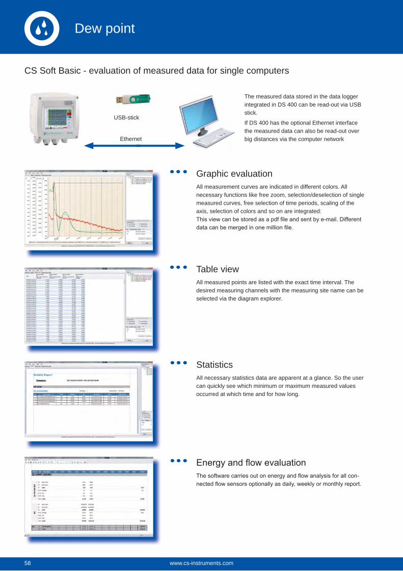
58
CS Soft Basic - evaluation of measured data for single computers
Graphic evaluationAll measurement curves are indicated in different colors. All necessary functions like free zoom, selection/deselection of single measured curves, free selection of time periods, scaling of the axis, selection of colors and so on are integrated:
Table viewAll measured points are listed with the exact time interval. The desired measuring channels with the measuring site name can be selected via the diagram explorer.
StatisticsAll necessary statistics data are apparent at a glance. So the user can quickly see which minimum or maximum measured values occurred at which time and for how long.
-
Ethernet
USB-stick
The measured data stored in the data logger integrated in DS 400 can be read-out via USB stick.
If DS 400 has the optional Ethernet interface the measured data can also be read-out over big distances via the computer network
www.cs-instruments.com58
Dew point
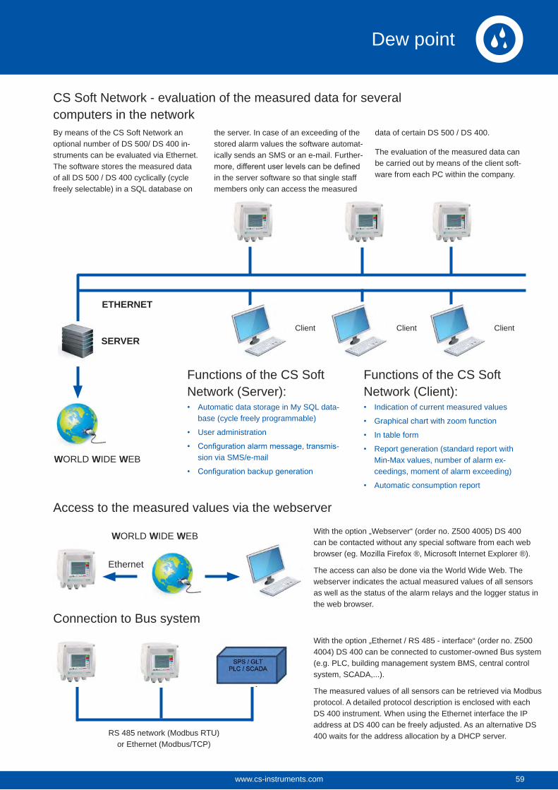
Client
CS Soft Network - evaluation of the measured data for several computers in the networkBy means of the CS Soft Network an optional number of DS 500/ DS 400 in-struments can be evaluated via Ethernet. The software stores the measured data of all DS 500 / DS 400 cyclically (cycle freely selectable) in a SQL database on
the server. In case of an exceeding of the stored alarm values the software automat-ically sends an SMS or an e-mail. Further-
in the server software so that single staff members only can access the measured
data of certain DS 500 / DS 400.
The evaluation of the measured data can be carried out by means of the client soft-ware from each PC within the company.
SERVER
ETHERNET
WORLD WIDE WEB
Functions of the CS Soft Network (Server):
Automatic data storage in My SQL data-base (cycle freely programmable)
User administration
-sion via SMS/e-mail
Functions of the CS Soft Network (Client):
Indication of current measured values
Graphical chart with zoom function
In table form
Report generation (standard report with Min-Max values, number of alarm ex-ceedings, moment of alarm exceeding)
Automatic consumption report
WORLD WIDE WEB With the option „Webserver“ (order no. Z500 4005) DS 400 can be contacted without any special software from each web browser (eg. Mozilla Firefox ®, Microsoft Internet Explorer ®).
The access can also be done via the World Wide Web. The webserver indicates the actual measured values of all sensors as well as the status of the alarm relays and the logger status in the web browser.
With the option „Ethernet / RS 485 - interface“ (order no. Z500 4004) DS 400 can be connected to customer-owned Bus system (e.g. PLC, building management system BMS, central control system, SCADA,...).
The measured values of all sensors can be retrieved via Modbus protocol. A detailed protocol description is enclosed with each DS 400 instrument. When using the Ethernet interface the IP address at DS 400 can be freely adjusted. As an alternative DS 400 waits for the address allocation by a DHCP server.RS 485 network (Modbus RTU)
or Ethernet (Modbus/TCP)
Access to the measured values via the webserver
Connection to Bus system
Client Client
Ethernet
59www.cs-instruments.com 59
Dew point
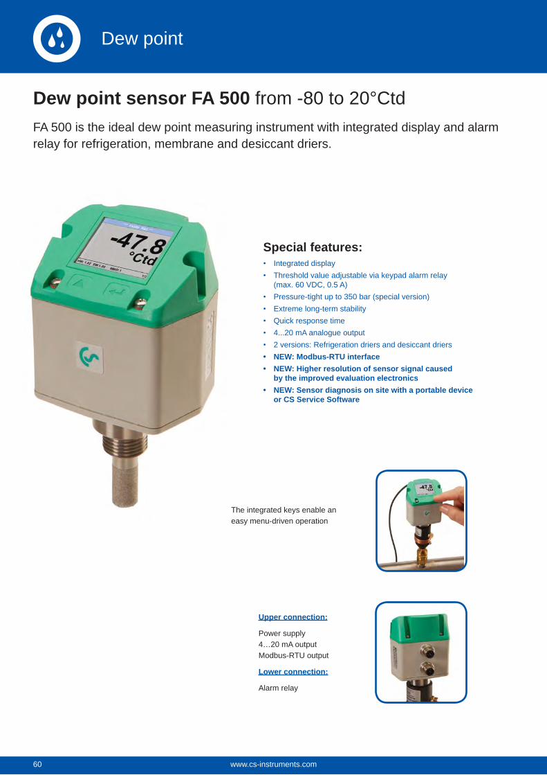
60
Special features:Integrated displayThreshold value adjustable via keypad alarm relay (max. 60 VDC, 0.5 A)Pressure-tight up to 350 bar (special version)Extreme long-term stabilityQuick response time4...20 mA analogue output2 versions: Refrigeration driers and desiccant driersNEW: Modbus-RTU interfaceNEW: Higher resolution of sensor signal caused by the improved evaluation electronicsNEW: Sensor diagnosis on site with a portable device or CS Service Software
Dew point sensor FA 500 from -80 to 20°CtdFA 500 is the ideal dew point measuring instrument with integrated display and alarmrelay for refrigeration, membrane and desiccant driers.
The integrated keys enable an easy menu-driven operation
Upper connection:
Power supply4…20 mA outputModbus-RTU output
Lower connection:
Alarm relay
www.cs-instruments.com60
Dew point
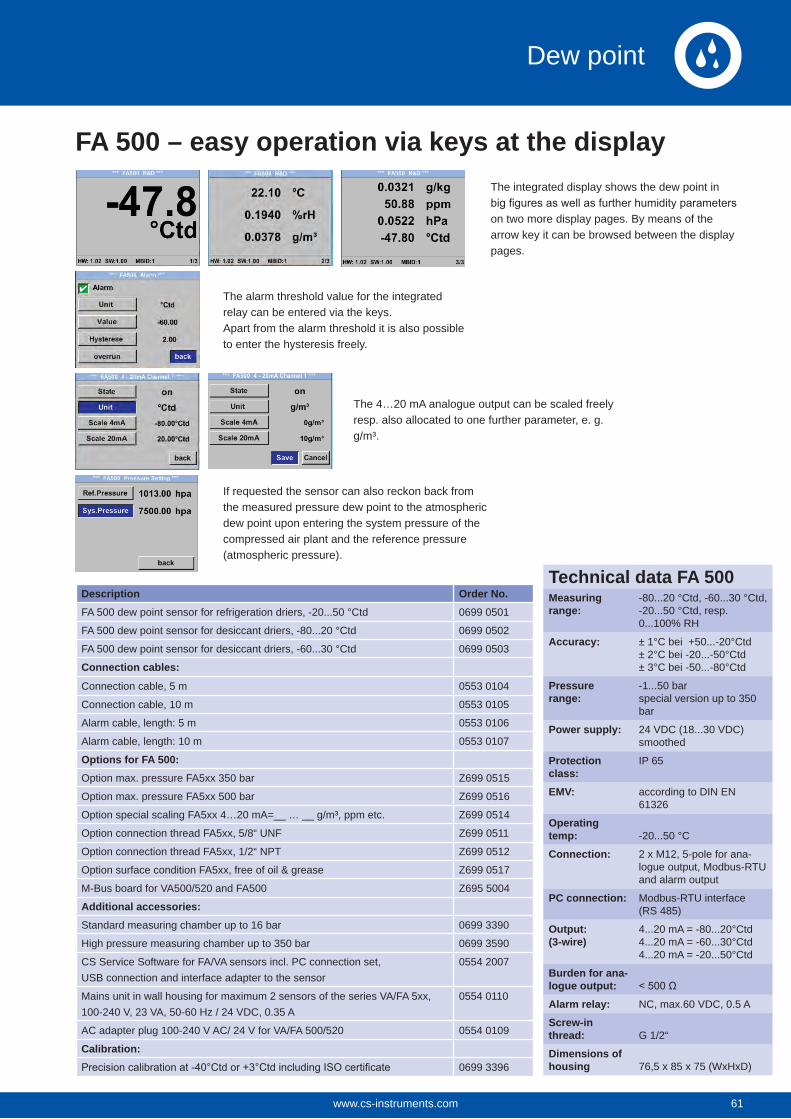
Description Order No.FA 500 dew point sensor for refrigeration driers, -20...50 °Ctd 0699 0501
FA 500 dew point sensor for desiccant driers, -80...20 °Ctd 0699 0502
FA 500 dew point sensor for desiccant driers, -60...30 °Ctd 0699 0503
Connection cables:
Connection cable, 5 m 0553 0104
Connection cable, 10 m 0553 0105
Alarm cable, length: 5 m 0553 0106
Alarm cable, length: 10 m 0553 0107
Options for FA 500:Option max. pressure FA5xx 350 bar Z699 0515
Option max. pressure FA5xx 500 bar Z699 0516
Option special scaling FA5xx 4…20 mA=__ … __ g/m³, ppm etc. Z699 0514
Option connection thread FA5xx, 5/8“ UNF Z699 0511
Option connection thread FA5xx, 1/2“ NPT Z699 0512
Option surface condition FA5xx, free of oil & grease Z699 0517
M-Bus board for VA500/520 and FA500 Z695 5004
Additional accessories:Standard measuring chamber up to 16 bar 0699 3390
High pressure measuring chamber up to 350 bar 0699 3590
CS Service Software for FA/VA sensors incl. PC connection set, USB connection and interface adapter to the sensor
0554 2007
Mains unit in wall housing for maximum 2 sensors of the series VA/FA 5xx,100-240 V, 23 VA, 50-60 Hz / 24 VDC, 0.35 A
0554 0110
AC adapter plug 100-240 V AC/ 24 V for VA/FA 500/520 0554 0109
Calibration:0699 3396
The integrated display shows the dew point in
on two more display pages. By means of the arrow key it can be browsed between the displaypages.
The alarm threshold value for the integrated relay can be entered via the keys.Apart from the alarm threshold it is also possibleto enter the hysteresis freely.
The 4…20 mA analogue output can be scaled freely resp. also allocated to one further parameter, e. g. g/m³.
If requested the sensor can also reckon back fromthe measured pressure dew point to the atmosphericdew point upon entering the system pressure of the compressed air plant and the reference pressure(atmospheric pressure).
FA 500 – easy operation via keys at the display
Technical data FA 500Measuring range:
-80...20 °Ctd, -60...30 °Ctd,-20...50 °Ctd, resp. 0...100% RH
Accuracy: ± 1°C bei +50...-20°Ctd± 2°C bei -20...-50°Ctd± 3°C bei -50...-80°Ctd
Pressure range:
-1...50 barspecial version up to 350 bar
Power supply: 24 VDC (18...30 VDC) smoothed
Protection class:
IP 65
EMV: according to DIN EN 61326
Operating temp: -20...50 °C
Connection: 2 x M12, 5-pole for ana-logue output, Modbus-RTU and alarm output
PC connection: Modbus-RTU interface(RS 485)
Output:(3-wire)
4...20 mA = -80...20°Ctd 4...20 mA = -60...30°Ctd4...20 mA = -20...50°Ctd
Burden for ana-logue output:Alarm relay: NC, max.60 VDC, 0.5 A
Screw-in thread: G 1/2“
Dimensions of housing 76,5 x 85 x 75 (WxHxD)
61www.cs-instruments.com 61
Dew point
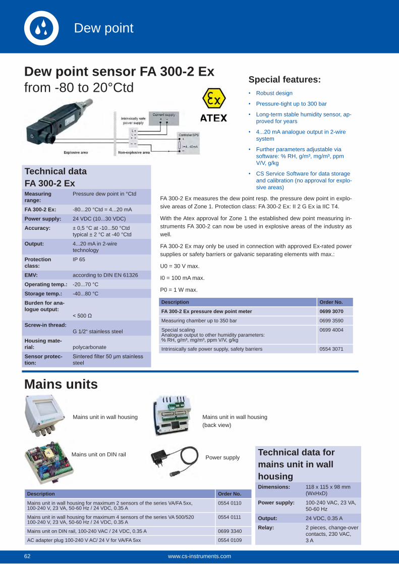
62
Description Order No.
Mains unit in wall housing for maximum 2 sensors of the series VA/FA 5xx,100-240 V, 23 VA, 50-60 Hz / 24 VDC, 0.35 A
0554 0110
Mains unit in wall housing for maximum 4 sensors of the series VA 500/520100-240 V, 23 VA, 50-60 Hz / 24 VDC, 0.35 A
0554 0111
Mains unit on DIN rail, 100-240 VAC / 24 VDC, 0.35 A 0699 3340
AC adapter plug 100-240 V AC/ 24 V for VA/FA 5xx 0554 0109
Special features:Robust design
Pressure-tight up to 300 bar
Long-term stable humidity sensor, ap-proved for years
4...20 mA analogue output in 2-wire system
Further parameters adjustable via software: % RH, g/m³, mg/m³, ppm V/V, g/kg
CS Service Software for data storage and calibration (no approval for explo-sive areas)
FA 300-2 Ex measures the dew point resp. the pressure dew point in explo-sive areas of Zone 1. Protection class: FA 300-2 Ex: II 2 G Ex ia IIC T4.
With the Atex approval for Zone 1 the established dew point measuring in-struments FA 300-2 can now be used in explosive areas of the industry as well.
FA 300-2 Ex may only be used in connection with approved Ex-rated power supplies or safety barriers or galvanic separating elements with max.:
U0 = 30 V max.
I0 = 100 mA max.
P0 = 1 W max.
Description Order No.
FA 300-2 Ex pressure dew point meter 0699 3070
Measuring chamber up to 350 bar 0699 3590
Special scalingAnalogue output to other humidity parameters:% RH, g/m³, mg/m³, ppm V/V, g/kg
0699 4004
Intrinsically safe power supply, safety barriers 0554 3071
Mains unit in wall housing
Mains unit on DIN rail
Mains unit in wall housing(back view)
Power supply
Dew point sensor FA 300-2 Ex from -80 to 20°Ctd
Mains units
Technical dataFA 300-2 ExMeasuring range:
Pressure dew point in °Ctd
FA 300-2 Ex: -80...20 °Ctd = 4...20 mA
Power supply: 24 VDC (10...30 VDC)
Accuracy: ± 0,5 °C at -10...50 °Ctdtypical ± 2 °C at -40 °Ctd
Output: 4...20 mA in 2-wiretechnology
Protection class:
IP 65
EMV: according to DIN EN 61326
Operating temp.: -20...70 °C
Storage temp.: -40...80 °C
Burden for ana-logue output:
Screw-in thread:G 1/2“ stainless steel
Housing mate-rial: polycarbonate
Sensor protec-tion: steel
Technical data for mains unit in wall housingDimensions: 118 x 115 x 98 mm
(WxHxD)
Power supply: 100-240 VAC, 23 VA, 50-60 Hz
Output: 24 VDC, 0.35 A
Relay: 2 pieces, change-over contacts, 230 VAC, 3 A
www.cs-instruments.com62
Dew point
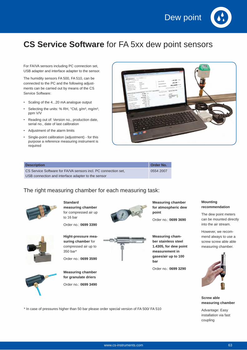
For FA/VA sensors including PC connection set, USB adapter and interface adapter to the sensor.
The humidity sensors FA 500, FA 510, can be connected to the PC and the following adjust-ments can be carried out by means of the CS Service Software:
Scaling of the 4...20 mA analogue output
Selecting the units: % RH, °Ctd, g/m³, mg/m³, ppm V/V
Reading out of: Version no., production date, serial no., date of last calibration
Adjustment of the alarm limits
Single-point calibration (adjustment) - for this purpose a reference measuring instrument is required
The right measuring chamber for each measuring task:
Standard measuring chamber for compressed air up to 16 bar
Order no.: 0699 3390
Hight-pressure mea-suring chamber for compressed air up to 350 bar*
Order no.: 0699 3590
Measuring chamber for granulate driers
Order no.: 0699 3490
Measuring chamber for atmospheric dew point
Order no.: 0699 3690
Mounting recommendation
The dew point meters can be mounted directly into the air stream.
However, we recom-mend always to use a screw screw able able measuring chamber.
Screw able measuring chamber
Advantage: Easy installation via fast coupling
Measuring cham-ber stainless steel 1.4305, for dew point measurement in gases/air up to 100 bar
Order no.: 0699 3290
CS Service Software for FA 5xx dew point sensors
* In case of pressures higher than 50 bar please order special version of FA 500/ FA 510
Description Order No.CS Service Software for FA/VA sensors incl. PC connection set, USB connection and interface adapter to the sensor
0554 2007
63www.cs-instruments.com 63
Dew point
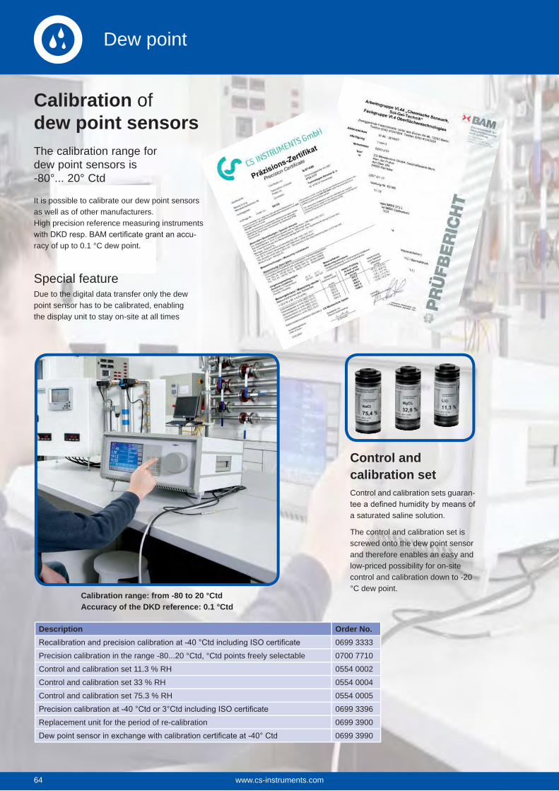
64
The calibration range for dew point sensors is -80°... 20° Ctd
Control and calibration setControl and calibration sets guaran-
a saturated saline solution.
The control and calibration set is screwed onto the dew point sensor and therefore enables an easy and low-priced possibility for on-site control and calibration down to -20 °C dew point.
Calibration range: from -80 to 20 °CtdAccuracy of the DKD reference: 0.1 °Ctd
Description Order No.0699 3333
Precision calibration in the range -80...20 °Ctd, °Ctd points freely selectable 0700 7710
Control and calibration set 11.3 % RH 0554 0002
Control and calibration set 33 % RH 0554 0004
Control and calibration set 75.3 % RH 0554 0005
0699 3396
Replacement unit for the period of re-calibration 0699 3900
0699 3990
Calibration of dew point sensors
It is possible to calibrate our dew point sensors as well as of other manufacturers. High precision reference measuring instruments
-racy of up to 0.1 °C dew point.
Special featureDue to the digital data transfer only the dew point sensor has to be calibrated, enabling the display unit to stay on-site at all times
www.cs-instruments.com64
Dew point
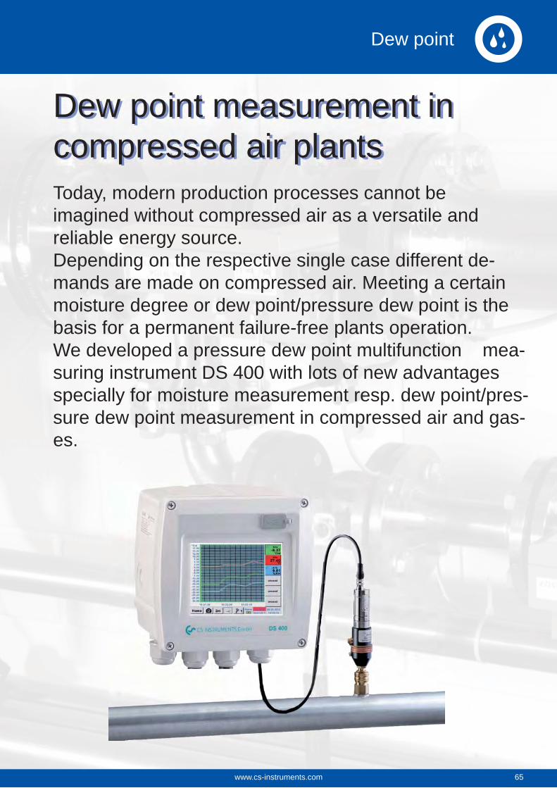
Today, modern production processes cannot be imagined without compressed air as a versatile and reliable energy source.Depending on the respective single case different de-mands are made on compressed air. Meeting a certain moisture degree or dew point/pressure dew point is the basis for a permanent failure-free plants operation. We developed a pressure dew point multifunction mea-suring instrument DS 400 with lots of new advantages specially for moisture measurement resp. dew point/pres-sure dew point measurement in compressed air and gas-es.
Dew point measurement in compressed air plants
65www.cs-instruments.com 65
Dew point
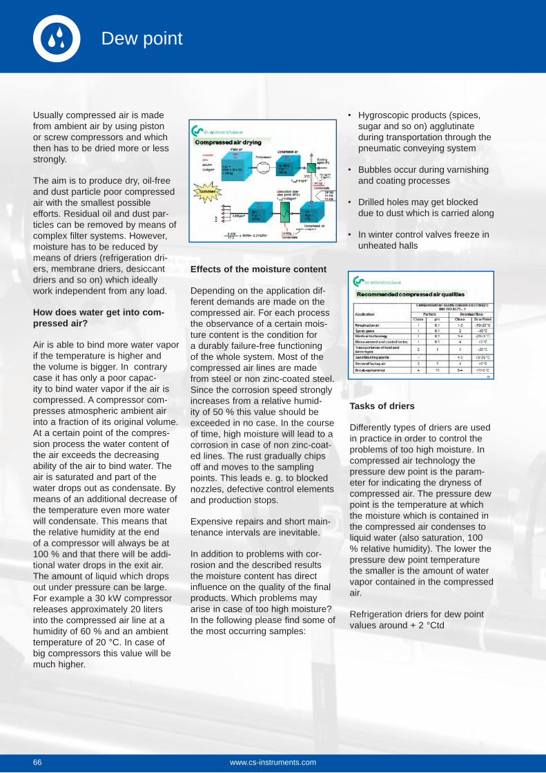
66
Usually compressed air is made from ambient air by using piston or screw compressors and which then has to be dried more or less strongly.
The aim is to produce dry, oil-free and dust particle poor compressed air with the smallest possible efforts. Residual oil and dust par-ticles can be removed by means of complex filter systems. However, moisture has to be reduced by means of driers (refrigeration dri-ers, membrane driers, desiccant driers and so on) which ideally work independent from any load.
How does water get into com-pressed air?
Air is able to bind more water vapor if the temperature is higher and the volume is bigger. In contrary case it has only a poor capac-ity to bind water vapor if the air is compressed. A compressor com-presses atmospheric ambient air into a fraction of its original volume. At a certain point of the compres-sion process the water content of the air exceeds the decreasing ability of the air to bind water. The air is saturated and part of the water drops out as condensate. By means of an additional decrease of the temperature even more water will condensate. This means that the relative humidity at the end of a compressor will always be at 100 % and that there will be addi-tional water drops in the exit air. The amount of liquid which drops out under pressure can be large. For example a 30 kW compressor releases approximately 20 liters into the compressed air line at a humidity of 60 % and an ambient temperature of 20 °C. In case of big compressors this value will be much higher.
Effects of the moisture content
Depending on the application dif-ferent demands are made on the compressed air. For each process the observance of a certain mois-ture content is the condition for a durably failure-free functioning of the whole system. Most of the compressed air lines are made from steel or non zinc-coated steel. Since the corrosion speed strongly increases from a relative humid-ity of 50 % this value should be exceeded in no case. In the course of time, high moisture will lead to a corrosion in case of non zinc-coat-ed lines. The rust gradually chips off and moves to the sampling points. This leads e. g. to blocked nozzles, defective control elements and production stops.
Expensive repairs and short main-tenance intervals are inevitable.
In addition to problems with cor-rosion and the described results the moisture content has direct influence on the quality of the final products. Which problems may arise in case of too high moisture? In the following please find some of the most occurring samples:
Hygroscopic products (spices, sugar and so on) agglutinate during transportation through the pneumatic conveying system
Bubbles occur during varnishing and coating processes
Drilled holes may get blocked due to dust which is carried along
In winter control valves freeze in unheated halls
Tasks of driers
Differently types of driers are used in practice in order to control the problems of too high moisture. In compressed air technology the pressure dew point is the param-eter for indicating the dryness of compressed air. The pressure dew point is the temperature at which the moisture which is contained in the compressed air condenses to liquid water (also saturation, 100 % relative humidity). The lower the pressure dew point temperature the smaller is the amount of water vapor contained in the compressed air.
Refrigeration driers for dew point values around + 2 °Ctd
www.cs-instruments.com66
Dew point
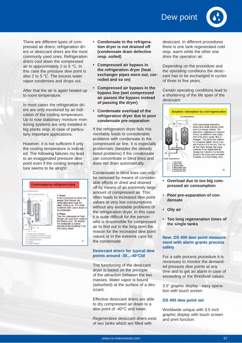
There are different types of com-pressed air driers; refrigeration dri-ers or desiccant driers are the most commonly used ones. Refrigeration driers cool down the compressed air to approximately 2 to 5 °C. In this case the pressure dew point is also 2 to 5 °C. The excess water vapor condenses and drops out.
After that the air is again heated up to room temperature.
In most cases the refrigeration dri-ers are only monitored by an indi-cation of the cooling temperature. Up to now stationary moisture mon-itoring systems are only installed in big plants resp. in case of particu-larly important applications.
However, it is not sufficient if only the cooling temperature is indicat-ed. The following failures my lead to an exaggerated pressure dew point even if the cooling tempera-ture seems to be alright:
Condensate in the refrigera-tion dryer is not drained off (condensate drain defective resp. soiled)
Compressed air bypass in the refrigeration dryer (heat exchanger pipes worn out, cor-roded and so on)
Compressed air bypass in the bypass line (wet compressed air passes the bypass instead of passing the dryer)
Condensate overload of the refrigeration dryer due to poor condensate pre-separation
If the refrigeration dryer fails this inevitably leads to considerable problems with condensate in the compressed air line. It is especially problematic (besides the already listed problems) if the condensate can concentrate in blind lines and does not drain automatically.
Condensate in blind lines can only be removed by means of consider-able efforts or dried and drained off by means of an extremely large amount of compressed air. This often leads to increased dew point values at very low consumptions without any avoidable problems of the refrigeration dryer. In this case it is quite difficult for the person who is responsible for compressed air to find out in the long-term the reason for the increased dew point values or in the extreme case for the condensate
Desiccant driers for typical dew points around -30...-40°Ctd
The functioning of the desiccant dryer is based on the principle of the attraction between the two masses. Water vapor is bound (adsorbed) at the surface of a des-iccant.
Effective desiccant driers are able to dry compressed air down to a dew point of -40°C and lower.
Regenerative desiccant driers exist of two tanks which are filled with
desiccant. In different procedures there is one tank regenerated cold resp. warm while the other one dries the operation air.
Depending on the procedure and the operating conditions the desic-cant has to be exchanged in cycles of three to five years.
Certain operating conditions lead to a shortening of the life span of the desiccant:
Overload due to too big com-pressed air consumption
Poor pre-separation of con-densate
Oily air
Too long regeneration times of the single tanks
New: DS 400 dew point measure-ment with alarm grants process safety
For a safe process procedure it is necessary to monitor the demand-ed pressure dew points at any time and to get an alarm in case of exceeding of the threshold values.
3.5” graphic display - easy opera-tion with touch screen
DS 400 dew point set
Worldwide unique with 3.5 inch graphic display with touch screen and print function
67www.cs-instruments.com 67
Dew point
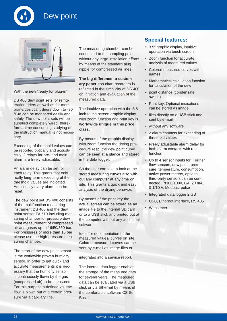
www.cs-instruments.com68
Dew point
With the new ”ready for plug-in”
DS 400 dew point sets for refrig-eration driers as well as for mem-brane/desiccant driers down to -80 °Ctd can be monitored easily and safely. The dew point sets will be supplied completely wired, there-fore a time consuming studying of the instruction manual is not neces-sary.
Exceeding of threshold values can be reported optically and acousti-cally. 2 relays for pre- and main alarm are freely adjustable.
An alarm delay can be set for each relay. This grants that only really long-term exceeding of the threshold values are indicated. Additionally every alarm can be reset.
The dew point set DS 400 consists of the multifunction measuring instrument DS 400 and the dew point sensor FA 510 including mea-suring chamber for pressure dew point measurement of compressed air and gases up to 16/50/350 bar. For pressures of more than 16 bar please use the high-pressure mea-suring chamber.
The heart of the dew point sensor is the worldwide proven humidity sensor. In order to get quick and accurate measurements it is nec-essary that the humidity sensor is continuously flown by the gas (compressed air) to be measured. For this purpose a defined volume flow is blown out at a certain pres-sure via a capillary line.
The measuring chamber can be connected to the sampling point without any large installation efforts by means of the standard plug nipple for compressed air lines.
The big difference to custom-ary paperless chart recorders is reflected in the simplicity of DS 400 on initiation and evaluation of the measured data.
The intuitive operation with the 3.5 inch touch screen graphic display with zoom function and print key is worldwide unique in this price class.
By means of the graphic display with zoom function the drying pro-cedure resp. the dew point curve can be seen at a glance and stored in the data logger.
So the user can take a look at the stored measuring curves also with-out any computer at any time on site. This grants a quick and easy analysis of the drying behavior.
By means of the print key the actual screen can be stored as an image file to the internal SD card or to a USB stick and printed out at the computer without any additional software.
Ideal for documentation of the measured values/ curves on site. Colored measured curves can be sent by e-mail as image files or
integrated into a service report.
The internal data logger enables the storage of the measured data for several years. The measured data can be evaluated via a USB stick or via Ethernet by means of the comfortable software CS Soft Basic.
Special features:3.5“ graphic display, intuitive operation via touch screen
Zoom function for accurate analysis of measured values
Colored measured curves with names
Mathematical calculation function for calculation of the dew
point distance (condensate switch)
Print key: Optional indications can be stored as image
sent by e-mail
without any software
2 alarm contacts for exceeding of threshold values
Freely adjustable alarm delay for both alarm contacts with reset function
Up to 4 sensor inputs for: Further -
sure, temperature, consumption, active power meters, optional third-party sensors can be con-nected: Pt100/1000, 0/4..20 mA, 0-1/10 V, Modbus, pulse
Integrated data logger 2 GB
USB, Ethernet interface, RS 485
Webserver
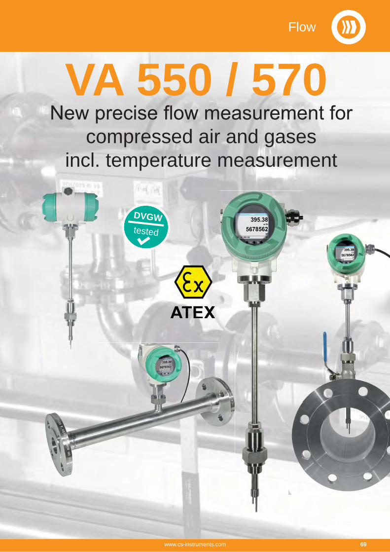
Flow
69www.cs-instruments.com
compressed air and gases
incl. temperature measurement
VA 550 / 570
DVGWtested
69

VA 550
compressed air and gases
pressure compensation is not necessary.
Due to its robust design, the aluminum die cast housing, the robust sensor tip made from stainless steel 1,4571, the new VA 550/ 570 -
ment e. g. of natural gas there is a version with a DVGW admission.
Contrary to the previously used bridge circuit the newly developed evaluation electronics records all measured values digitally. This allows very precise and fast measurements with a wide temperature range of up to 180 °C. The measuring span is 1...1000 and
VA 550/ 570 has an integrated Modbus output as a standard with which all parameters like Nm³/h, Nm³, Nm/s, Nl/min, Nl/s, kg/h, kg/min, ft/min, °C etc. can be transferred. All parameters can be adjusted directly at the instrument (via display) or via the PI 500 hand-held measuring instrument resp. the Service Software. Of course there are also 1 x 4...20 mA analogue output available for the
A remote diagnosis can be carried out via Modbus and all relevant parameters can be checked and changed if necessary. So it is -
sion in case of changed process conditions.
Via remote diagnosis and status update e. g. temperature exceeding, failures of the sensor or the calibration date can be determined.
Applicable in all sectors like e. g.:
Chemistry, petrol chemistryNatural gas, methane...Pharmaceutical industryFood production BreweriesDiariesPower plantsSemiconductor/ electronicsAutomotive industry
Application range:
Ideal also for the outdoor area
Compressed air measurement and distribution
Leakage measurement of compressed air and gases
Flow measurement of gases like e. g. nitrogen, argon, carbon dioxide, oxygen and so on
Flow measurement in vacuum systems
Flow measurement of explosive gases like natural gas, methane, pro-pane, hydrogen with ATEX approval
Flow measurement of corrosive, acid gases like e. g. biogas with dif-ferent gas mixtures
Measurement of oxygen and natural gas at gas burners
Flow measurement of gas mixtures like e. g. forming gas
DVGWtestedVA 550
immersionsensor * German Technical and
Scientific Association for Gas and Water
Available with option: Ethernet Modbus/TCP
Flow
70 www.cs-instruments.com
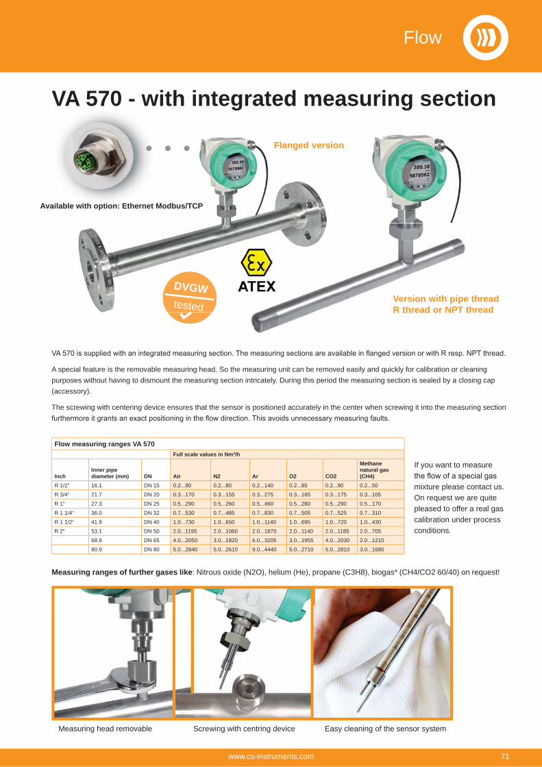
A special feature is the removable measuring head. So the measuring unit can be removed easily and quickly for calibration or cleaning purposes without having to dismount the measuring section intricately. During this period the measuring section is sealed by a closing cap (accessory).
The screwing with centering device ensures that the sensor is positioned accurately in the center when screwing it into the measuring section
VA 570 - with integrated measuring section
Measuring ranges of further gases like: Nitrous oxide (N2O), helium (He), propane (C3H8), biogas* (CH4/CO2 60/40) on request!
Flow measuring ranges VA 570Full scale values in Nm³/h
InchInner pipe diameter (mm) DN Air N2 Ar O2 CO2
Methanenatural gas (CH4)
R 1/2“ 16.1 DN 15 0.2...90 0.2...80 0.2...140 0.2...85 0.2...90 0.2...50
R 3/4“ 21.7 DN 20 0.3...170 0.3...155 0.3...275 0.3...165 0.3...175 0.3...105
R 1“ 27.3 DN 25 0.5...290 0.5...260 0.5...460 0.5...280 0.5...290 0.5...170
R 1 1/4“ 36.0 DN 32 0.7...530 0.7...485 0.7...830 0.7...505 0.7...525 0.7...310
R 1 1/2“ 41.9 DN 40 1.0...730 1.0...650 1.0...1140 1.0...695 1.0...720 1.0...430
R 2“ 53.1 DN 50 2.0...1195 2.0...1060 2.0...1870 2.0...1140 2.0...1185 2.0...705
68.9 DN 65 4.0...2050 3.0...1820 6.0...3205 3.0...1955 4.0...2030 2.0...1210
80.9 DN 80 5.0...2840 5.0...2610 9.0...4440 5.0...2710 5.0...2810 3.0...1680
If you want to measure
mixture please contact us. On request we are quite pleased to offer a real gas calibration under process conditions.
Version with pipe threadR thread or NPT thread
Flanged version
Measuring head removable Screwing with centring device Easy cleaning of the sensor system
Flanged vers
DVGWtested
Version with pipe R thread or NPT th
Available with option: Ethernet Modbus/TCP
Flow
71www.cs-instruments.com
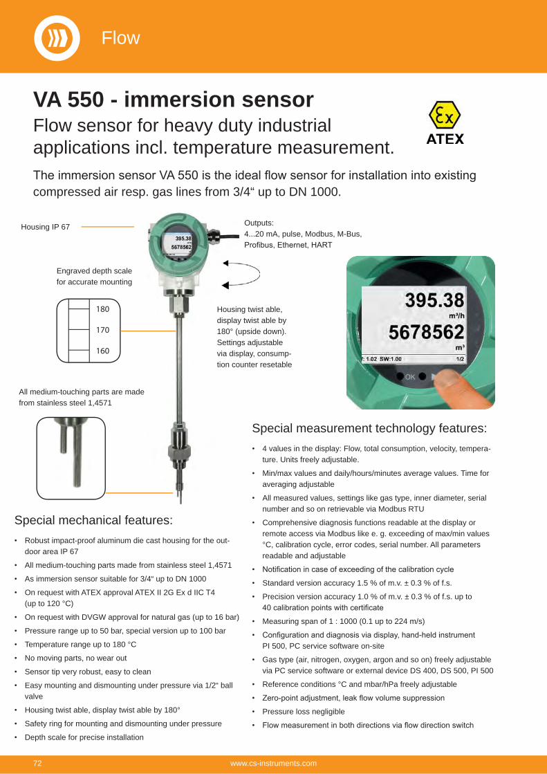
compressed air resp. gas lines from 3/4“ up to DN 1000.
VA 550 - immersion sensorFlow sensor for heavy duty industrial applications incl. temperature measurement.
Special mechanical features:Robust impact-proof aluminum die cast housing for the out-door area IP 67
All medium-touching parts made from stainless steel 1,4571
As immersion sensor suitable for 3/4“ up to DN 1000
On request with ATEX approval ATEX II 2G Ex d IIC T4 (up to 120 °C)
On request with DVGW approval for natural gas (up to 16 bar)
Pressure range up to 50 bar, special version up to 100 bar
Temperature range up to 180 °C
No moving parts, no wear out
Sensor tip very robust, easy to clean
Easy mounting and dismounting under pressure via 1/2“ ball valve
Housing twist able, display twist able by 180°
Safety ring for mounting and dismounting under pressure
Depth scale for precise installation
Housing IP 67 Outputs:4...20 mA, pulse, Modbus, M-Bus,
Housing twist able, display twist able by 180° (upside down).Settings adjustable via display, consump-tion counter resetable
Special measurement technology features:4 values in the display: Flow, total consumption, velocity, tempera-ture. Units freely adjustable.
Min/max values and daily/hours/minutes average values. Time for averaging adjustable
All measured values, settings like gas type, inner diameter, serial number and so on retrievable via Modbus RTU
Comprehensive diagnosis functions readable at the display or remote access via Modbus like e. g. exceeding of max/min values °C, calibration cycle, error codes, serial number. All parameters readable and adjustable
Standard version accuracy 1.5 % of m.v. ± 0.3 % of f.s.
Precision version accuracy 1.0 % of m.v. ± 0.3 % of f.s. up to
Measuring span of 1 : 1000 (0.1 up to 224 m/s)
PI 500, PC service software on-site
Gas type (air, nitrogen, oxygen, argon and so on) freely adjustable via PC service software or external device DS 400, DS 500, PI 500
Reference conditions °C and mbar/hPa freely adjustable
Pressure loss negligible
All medium-touching parts are made from stainless steel 1,4571
180
170
160
Engraved depth scale for accurate mounting
Flow
72 www.cs-instruments.com
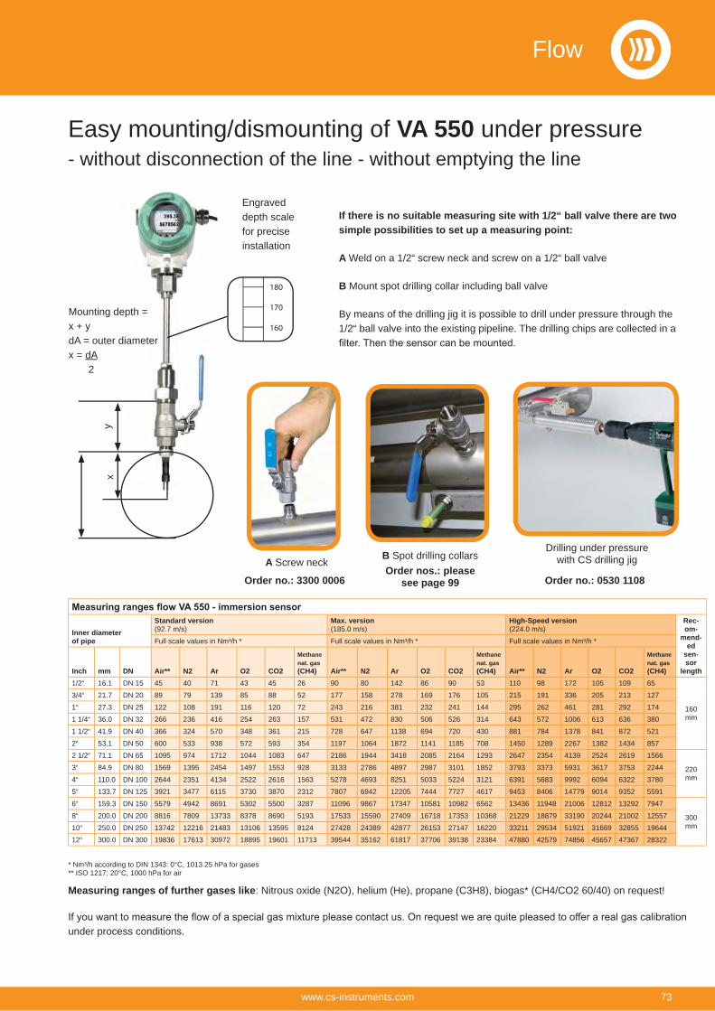
If there is no suitable measuring site with 1/2“ ball valve there are two simple possibilities to set up a measuring point:
A Weld on a 1/2“ screw neck and screw on a 1/2“ ball valve
B Mount spot drilling collar including ball valve
By means of the drilling jig it is possible to drill under pressure through the 1/2“ ball valve into the existing pipeline. The drilling chips are collected in a
Drilling under pressure with CS drilling jigA Screw neck
B Spot drilling collars
Mounting depth = x + ydA = outer diameterx = dA 2
yx
Measuring ranges of further gases like: Nitrous oxide (N2O), helium (He), propane (C3H8), biogas* (CH4/CO2 60/40) on request!
Order no.: 3300 0006Order nos.: please
see page 99
Inner diameterof pipe
Standard version(92.7 m/s)
Max. version(185.0 m/s)
High-Speed version(224.0 m/s)
Rec-om-
mend-ed
sen-sor
length
Full scale values in Nm³/h * Full scale values in Nm³/h * Full scale values in Nm³/h *
Inch mm DN Air** N2 Ar O2 CO2
Methanenat. gas (CH4) Air** N2 Ar O2 CO2
Methanenat. gas (CH4) Air** N2 Ar O2 CO2
Methanenat. gas (CH4)
1/2“ 16.1 DN 15 45 40 71 43 45 26 90 80 142 86 90 53 110 98 172 105 109 65
160 mm
3/4“ 21.7 DN 20 89 79 139 85 88 52 177 158 278 169 176 105 215 191 336 205 213 127
1“ 27.3 DN 25 122 108 191 116 120 72 243 216 381 232 241 144 295 262 461 281 292 174
1 1/4“ 36.0 DN 32 266 236 416 254 263 157 531 472 830 506 526 314 643 572 1006 613 636 380
1 1/2“ 41.9 DN 40 366 324 570 348 361 215 728 647 1138 694 720 430 881 784 1378 841 872 521
2“ 53.1 DN 50 600 533 938 572 593 354 1197 1064 1872 1141 1185 708 1450 1289 2267 1382 1434 857
2 1/2“ 71.1 DN 65 1095 974 1712 1044 1083 647 2186 1944 3418 2085 2164 1293 2647 2354 4139 2524 2619 1566
220 mm
3“ 84.9 DN 80 1569 1395 2454 1497 1553 928 3133 2786 4897 2987 3101 1852 3793 3373 5931 3617 3753 2244
4“ 110.0 DN 100 2644 2351 4134 2522 2616 1563 5278 4693 8251 5033 5224 3121 6391 5683 9992 6094 6322 3780
5“ 133.7 DN 125 3921 3477 6115 3730 3870 2312 7807 6942 12205 7444 7727 4617 9453 8406 14779 9014 9352 5591
6“ 159.3 DN 150 5579 4942 8691 5302 5500 3287 11096 9867 17347 10581 10982 6562 13436 11948 21006 12812 13292 7947
300 mm
8“ 200.0 DN 200 8816 7809 13733 8378 8690 5193 17533 15590 27409 16718 17353 10368 21229 18879 33190 20244 21002 12557
10“ 250.0 DN 250 13742 12216 21483 13106 13595 8124 27428 24389 42877 26153 27147 16220 33211 29534 51921 31669 32855 19644
12“ 300.0 DN 300 19836 17613 30972 18895 19601 11713 39544 35162 61817 37706 39138 23384 47880 42579 74856 45657 47367 28322
Order no.: 0530 1108
under process conditions.
180
170
160
Engraved depth scale for precise installation
Easy mounting/dismounting of VA 550 under pressure- without disconnection of the line - without emptying the line
* Nm³/h according to DIN 1343: 0°C, 1013.25 hPa for gases** ISO 1217: 20°C, 1000 hPa for air
Flow
73www.cs-instruments.com
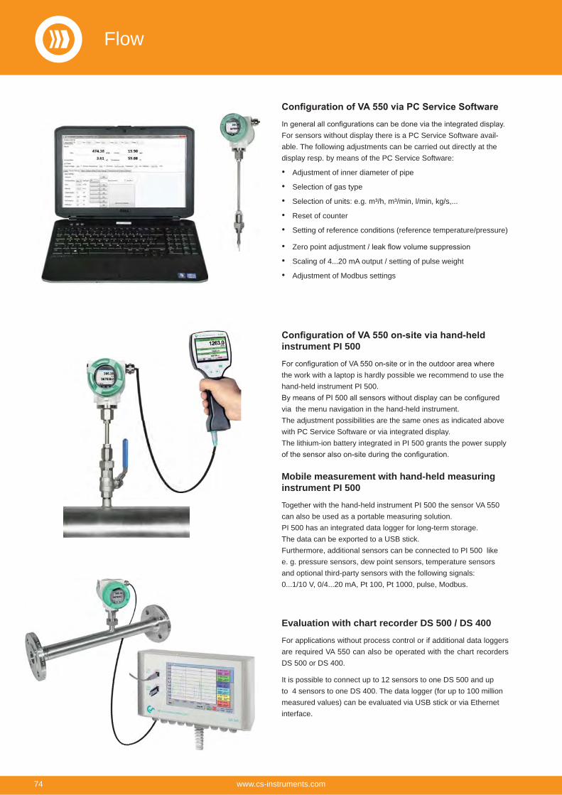
For sensors without display there is a PC Service Software avail-able. The following adjustments can be carried out directly at the display resp. by means of the PC Service Software:
Adjustment of inner diameter of pipe
Selection of gas type
Selection of units: e.g. m³/h, m³/min, l/min, kg/s,...
Reset of counter
Setting of reference conditions (reference temperature/pressure)
Zero point adjustment /
Scaling of 4...20 mA output / setting of pulse weight
Adjustment of Modbus settings
instrument PI 500
the work with a laptop is hardly possible we recommend to use the hand-held instrument PI 500.
via the menu navigation in the hand-held instrument. The adjustment possibilities are the same ones as indicated above with PC Service Software or via integrated display. The lithium-ion battery integrated in PI 500 grants the power supply
Mobile measurement with hand-held measuring instrument PI 500
Together with the hand-held instrument PI 500 the sensor VA 550 can also be used as a portable measuring solution. PI 500 has an integrated data logger for long-term storage.The data can be exported to a USB stick.Furthermore, additional sensors can be connected to PI 500 like e. g. pressure sensors, dew point sensors, temperature sensors and optional third-party sensors with the following signals: 0...1/10 V, 0/4...20 mA, Pt 100, Pt 1000, pulse, Modbus.
Evaluation with chart recorder DS 500 / DS 400
For applications without process control or if additional data loggers are required VA 550 can also be operated with the chart recorders DS 500 or DS 400.
It is possible to connect up to 12 sensors to one DS 500 and up to 4 sensors to one DS 400. The data logger (for up to 100 million measured values) can be evaluated via USB stick or via Ethernet interface.
Flow
74 www.cs-instruments.com
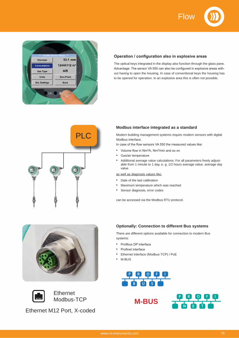
The optical keys integrated in the display also function through the glass pane. -
out having to open the housing. In case of conventional keys the housing has to be opened for operation. In an explosive area this is often not possible.
Modbus interface integrated as a standard
Modern building management systems require modern sensors with digital Modbus interface.
Gas/air temperatureAdditional average value calculations: For all parameters freely adjust-able from 1 minute to 1 day, e. g. 1/2 hours average value, average day value
as well as diagnosis values like:
Date of the last calibrationMaximum temperature which was reachedSensor diagnosis, error codes
can be accessed via the Modbus RTU protocol.
Optionally: Connection to different Bus systems
There are different options available for connection to modern Bus systems:
Ethernet interface (Modbus-TCP) / PoEM-BUS
PLC
P R O F I
N E T
P R O F I
B U S
EthernetModbus-TCP M-BUS
Ethernet M12 Port, X-coded
Flow
75www.cs-instruments.com
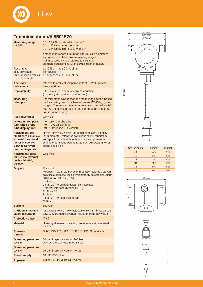
134,8(max.)(Ex Version)
H (m
ax.)
99,8 (max.)
L
156(max.)
Sensor length L [mm] H [mm]C1 220 441
C2 300 521C3 400 621C4 500 721C5 600 821C7 160 361
Technical data VA 550/ 570Measuring rangeVA 550:
0.1...92,7 Nm/s, standard version*0.1...185 Nm/s, max. version*0.1...224 Nm/s, high speed version*
* measuring ranges Nm³/h for different pipe diameters
* all measured values referred to DIN 1343 standard conditions 0 °C and 1013 mbar ex factory
Accuracy: accuracy class (m.v.: of meas. value)(f.s.: of full scale)
± 1.5 % of m.v. ± 0.3 % of f.s. on request± 1.0 % of m.v. ± 0.3 % of f.s.
Accuracy indications
referred to ambient temperature 22°C ± 2°C, system pressure 6 bar
Repeatability: 0.25 % of m.v. in case of correct mounting (mounting aid, position, inlet section)
Measuring principle: on the cooling down of a heated sensor PT 45 by bypass-
ing gas. The ambient temperature is measured with a PT 100. An additional pressure and temperature compensa-tion is not necessary.
Response time: t90 < 3 s
Operating tempera-ture range probe tube/display unit:
-40...180 °C probe tube-40...70°C display unit -40...120°C for ATEX version
Adjustment pos-sibilities via display, external hand-held meter PI 500, PC Service Software, remote diagnosis:
Nm³/h, Nm³/min, Nl/min, l/s, ft/min, cfm, kg/h, kg/min, inner diameter, reference conditions °C/°F, mbar/hPa,
scaling of analogue output 4...20 mA, pulse/alarm, error codes and so on
Adjustment possi-bilities via external device DS 400, DS 500
Gas type
Outputs: Standard:Modbus RTU, 4...20 mA activ (not galv. isolated), galvani-cally isolated pulse (pulse weight freely selectable), alarm relais (max. 48 VDC, 0.5A)Optional:2 x 4...20 mA outputs galvanically isolatedEthernet Interface (Modbus/TCP)
2 x 4...20 mA outputs passiveM-Bus
Burden: 500 Ohm
Additional average value calculation:
for all parameters freely adjustable from 1 minute up to 1 day, e. g. 1/2 hours average value, average day value
Protection class : IP 67
Material: Housing aluminium die cast, probe tube stainless steel 1,4571
Screw-inthread:
G 1/2“ ISO 228, NPT 1/2“, R 1/2“, PT 1/2“ available
Operating pressureVA 550:
50 bar; in special version 100 bar(For DVGW approval max. 16 bar)
Operating pressureVA 570: 16 bar; in special version 40 bar
Power supply: 18...36 VDC, 5 W
Approval: ATEX II 2G Ex d IIC T4, DVGW
Flow
76 www.cs-instruments.com
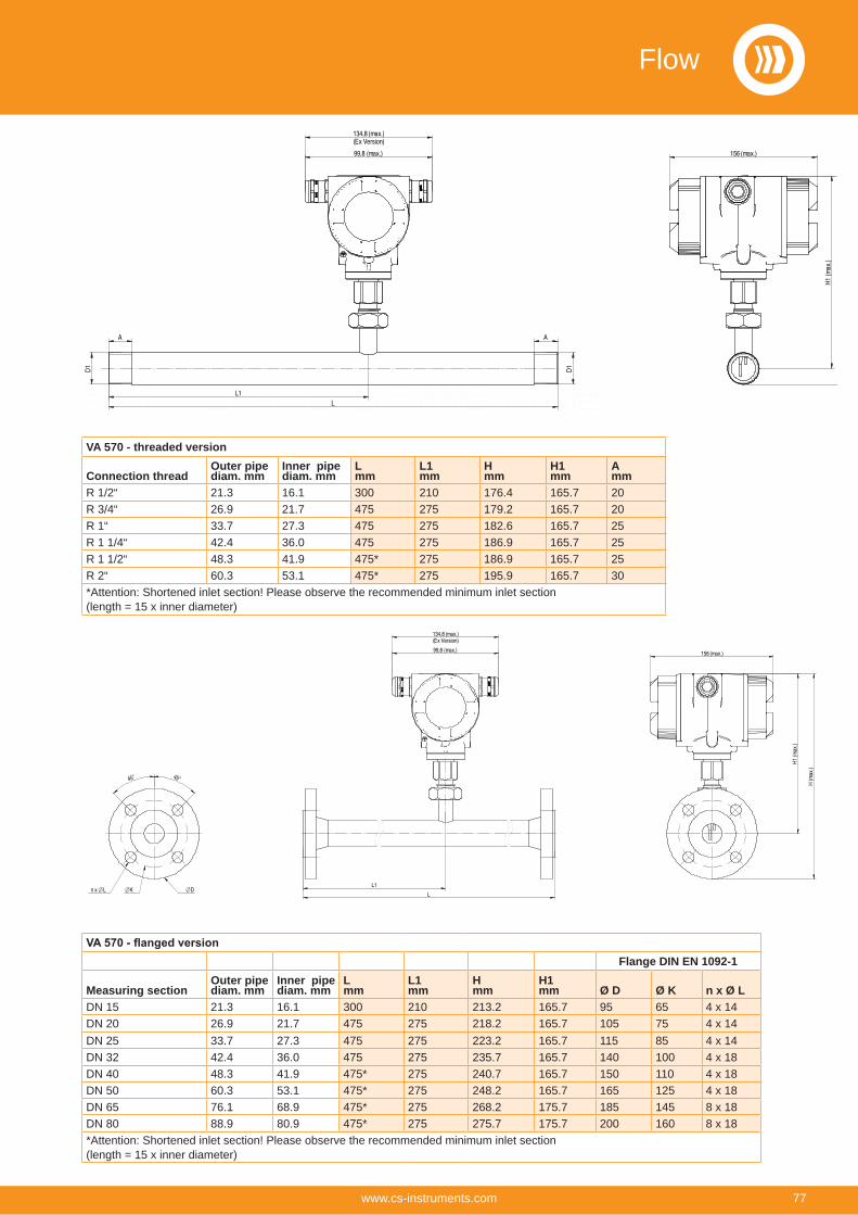
VA 570 - threaded version
Connection threadOuter pipe diam. mm
Inner pipe diam. mm
Lmm
L1mm
Hmm
H1mm
Amm
R 1/2“ 21.3 16.1 300 210 176.4 165.7 20R 3/4“ 26.9 21.7 475 275 179.2 165.7 20R 1“ 33.7 27.3 475 275 182.6 165.7 25R 1 1/4“ 42.4 36.0 475 275 186.9 165.7 25R 1 1/2“ 48.3 41.9 475* 275 186.9 165.7 25R 2“ 60.3 53.1 475* 275 195.9 165.7 30*Attention: Shortened inlet section! Please observe the recommended minimum inlet section (length = 15 x inner diameter)
Flange DIN EN 1092-1
Measuring sectionOuter pipe diam. mm
Inner pipe diam. mm
Lmm
L1mm
Hmm
H1mm Ø D Ø K n x Ø L
DN 15 21.3 16.1 300 210 213.2 165.7 95 65 4 x 14DN 20 26.9 21.7 475 275 218.2 165.7 105 75 4 x 14DN 25 33.7 27.3 475 275 223.2 165.7 115 85 4 x 14DN 32 42.4 36.0 475 275 235.7 165.7 140 100 4 x 18DN 40 48.3 41.9 475* 275 240.7 165.7 150 110 4 x 18DN 50 60.3 53.1 475* 275 248.2 165.7 165 125 4 x 18DN 65 76.1 68.9 475* 275 268.2 175.7 185 145 8 x 18DN 80 88.9 80.9 475* 275 275.7 175.7 200 160 8 x 18*Attention: Shortened inlet section! Please observe the recommended minimum inlet section (length = 15 x inner diameter)
134,8(max.)(Ex Version)
99,8 (max.) 156(max.)
H1 (m
ax.)
A A
D1
L1L
D1
45° 45°
K D n x LL1
L
134,8(max.)(Ex Version)
99,8 (max.)
H1 (m
ax.)
H (m
ax.)
156(max.)
Flow
77www.cs-instruments.com
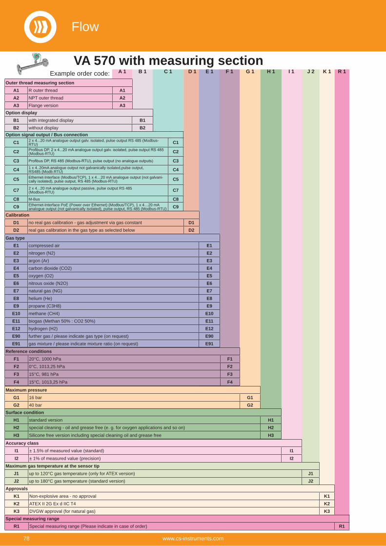
R 1J 2G 1 K 1B 1A 1 C 1 D 1 E 1 I 1H 1F 1
Outer thread measuring sectionA1 R outer thread A1A2 NPT outer thread A2A3 Flange version A3
Option displayB1 with integrated display B1B2 without display B2
Option signal output / Bus connectionC1 2 x 4...20 mA analogue output galv. isolated, pulse output RS 485 (Modbus-
RTU) C1
C2 (Modbus-RTU) C2
C3 C3
C4 1 x 4..20mA analogue output not galvanically isolated,pulse output,RS485 (Modb.RTU) C4
C5 Ethernet-Interface (Modbus/TCP), 1 x 4…20 mA analogue output (not galvani-cally isolated), pulse output, RS 485 (Modbus-RTU) C5
C7 2 x 4...20 mA analogue output passive, pulse output RS 485 (Modbus-RTU) C7
C8 M-Bus C8C9 Ethernet-Interface PoE (Power over Ethernet) (Modbus/TCP), 1 x 4…20 mA
analogue output (not galvanically isolated), pulse output, RS 485 (Modbus-RTU) C9
CalibrationD1 no real gas calibration - gas adjustment via gas constant D1D2 real gas calibration in the gas type as selected below D2
Gas typeE1 compressed air E1E2 nitrogen (N2) E2E3 argon (Ar) E3E4 carbon dioxide (CO2) E4E5 oxygen (O2) E5E6 nitrous oxide (N2O) E6E7 natural gas (NG) E7E8 helium (He) E8E9 propane (C3H8) E9E10 methane (CH4) E10E11 biogas (Methan 50% : CO2 50%) E11E12 hydrogen (H2) E12E90 further gas / please indicate gas type (on request) E90E91 gas mixture / please indicate mixture ratio (on request) E91
ApprovalsK1 Non-explosive area - no approval K1K2 ATEX II 2G Ex d IIC T4 K2K3 DVGW approval (for natural gas) K3
Reference conditionsF1 20°C, 1000 hPa F1F2 0°C, 1013,25 hPa F2F3 15°C, 981 hPa F3F4 15°C, 1013,25 hPa F4
Maximum pressureG1 16 bar G1G2 40 bar G2
Surface conditionH1 standard version H1H2 special cleaning - oil and grease free (e. g. for oxygen applications and so on) H2H3 Silicone free version including special cleaning oil and grease free H3
Accuracy classI1 ± 1.5% of measured value (standard) I1I2 ± 1% of measured value (precision) I2
Maximum gas temperature at the sensor tipJ1 up to 120°C gas temperature (only for ATEX version) J1J2 up to 180°C gas temperature (standard version) J2
Example order code:VA 570 with measuring section
Special measuring rangeR1 Special measuring range (Please indicate in case of order) R1
Flow
78 www.cs-instruments.com
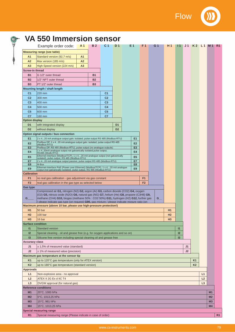
M 1J 1D 1B 2 C 1 F 1 G 1 H 1 L 1K 2 E 1 I 1
Screw-in threadB1 G 1/2“ outer thread B1B2 1/2“ NPT outer thread B2B3 PT 1/2“ outer thread B3
Mounting length / shaft lengthC1 220 mm C1C2 300 mm C2C3 400 mm C3C4 500 mm C4C5 600 mm C5C7 160 mm C7
Option displayD1 with integrated display D1D2 without display D2
Option signal outputs / bus connectionE1 2 x 4...20 mA analogue output galv. isolated, pulse output RS 485 (Modbus-RTU) E1
E2 (Modbus-RTU) E2E3 E3E4 1 x 4..20mA analogue output not galvanically isolated,pulse output,
RS485 (Modb.RTU) E4
E5 Ethernet-Interface (Modbus/TCP), 1 x 4…20 mA analogue output (not galvanically isolated), pulse output, RS 485 (Modbus-RTU) E5
E7 2 x 4...20 mA analogue output passive, pulse output RS 485 (Modbus-RTU) E7E8 M-Bus E8E9 Ethernet-Interface PoE (Power over Ethernet) (Modbus/TCP), 1 x 4…20 mA analogue
output (not galvanically isolated), pulse output, RS 485 (Modbus-RTU) E9
ApprovalsL1 Non-explosive area - no approval L1L2 ATEX II 2G Ex d IIC T4 L2L3 DVGW approval (for natural gas) L3
Maximum gas temperature at the sensor tipK1 up to 120°C gas temperature (only for ATEX version) K1K2 up to 180°C gas temperature (standard version) K2
A 1
Measuring range (see table)A1 Standard version (92,7 m/s) A1A2 Max version (185 m/s) A2A3 High-Speed version (224 m/s) A3
Surface conditionI1 Standard version I1I2 Special cleaning - oil and grease free (e.g. for oxygen applications and so on) I2I3 Silicone free version including special cleaning oil and grease free I3
CalibrationF1 no real gas calibration - gas adjustment via gas constant F1F2 real gas calibration in the gas type as selected below F2
Gas type
G____
Compressed air G1, nitrogen (N2) G2, argon (Ar) G3, carbon dioxide (CO2) G4, oxygen (O2) G5, nitrous oxide (N2O) G6, natural gas (NG) G7, helium (He) G8, propane (C3H8) G9, methane (CH4) G10, biogas (methane 50% : CO2 50%) G11, hydrogen (H2) G12, further gas / please indicate gas type (on request) G90, gas mixture / please indicate mixture ratio (on request) G91
G__
Accuracy classJ1 ± 1,5% of measured value (standard) J1J2 ± 1% of measured value (precision) J2
Maximum pressure (above 10 bar, please use high-pressure protection!)H1 50 bar H1H2 100 bar H2H3 16 bar H3
Reference conditionsM1 20°C, 1000 hPa M1M2 0°C, 1013,25 hPa M2M3 15°C, 981 hPa M3M4 15°C, 1013,25 hPa M4
Example order code:VA 550 Immersion sensor
R1
Special measuring rangeR1 Special measuring range (Please indicate in case of order) R1
Flow
79www.cs-instruments.com
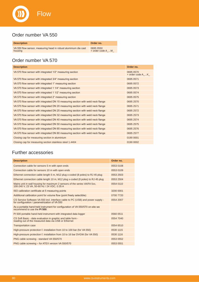
Description Order no.
housing0695 0550+ order code A_...M_
Description Order no.
0695 0570+ order code A_...K_
0695 0571
0695 0572
0695 0573
0695 0574
0695 0575
0695 2570
0695 2571
0695 2572
0695 2573
0695 2574
0695 2575
0695 2576
0695 2577
Closing cap for measuring section in aluminium 0190 0001
Closing cap for measuring section stainless steel 1.4404 0190 0002
Order number VA 550
Order number VA 570
Description Order no.
Connection cable for sensors 5 m with open ends 0553 0108
Connection cable for sensors 10 m with open ends 0553 0109
Ethernet connection cable length 5 m, M12 plug x-coded (8 poles) to RJ 45 plug 0553 2503
Ethernet connection cable length 10 m, M12 plug x-coded (8 poles) to RJ 45 plug 0553 2504
Mains unit in wall housing for maximum 2 sensors of the series VA/FA 5xx,100-240 V, 23 VA, 50-60 Hz / 24 VDC, 0.35 A
0554 0110
3200 0001
0700 7720
CS Service Software VA 550 incl. interface cable to PC (USB) and power supply - 0554 2007
recommend to use the PI 500:
PI 500 portable hand-held instrument with integrated data logger 0560 0511
CS Soft Basic - data evaluation in graphic and table form - reading out of the measured data via USB or Ethernet
0554 7040
Transportation case 0554 6510
High-pressure protection f. installation from 10 to 100 bar (for VA 550) 0530 1115
High-pressure protection f. installation from 10 to 16 bar DVGW (for VA 550) 0530 1116
PNG cable screwing - standard VA 550/570 0553 0552
PNG cable screwing – for ATEX version VA 550/570 0553 0551
Further accessories
Flow
80 www.cs-instruments.com
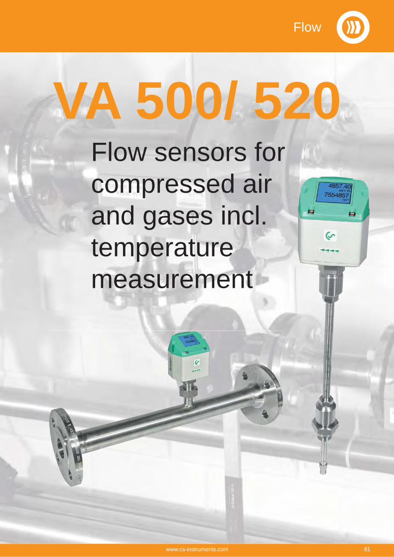
Flow sensors for compressed air and gases incl.temperature measurement
VA 500/ 520Flow
81www.cs-instruments.com
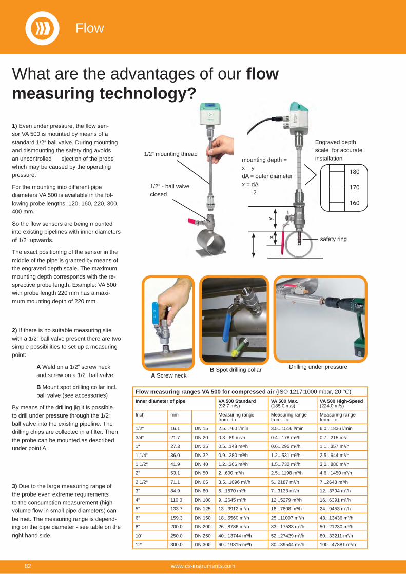
What are the advantages of our flow measuring technology?
Flow measuring ranges VA 500 for compressed air (ISO 1217:1000 mbar, 20 °C)Inner diameter of pipe VA 500 Standard
(92.7 m/s)VA 500 Max.(185.0 m/s)
VA 500 High-Speed(224.0 m/s)
Inch mm Measuring range from to
Measuring range from to
Measuring range from to
1/2“ 16.1 DN 15 2.5...760 l/min 3.5...1516 l/min 6.0...1836 l/min
3/4“ 21.7 DN 20 0.3...89 m³/h 0.4...178 m³/h 0.7...215 m³/h
1“ 27.3 DN 25 0.5...148 m³/h 0.6...295 m³/h 1.1...357 m³/h
1 1/4“ 36.0 DN 32 0.9...280 m³/h 1.2...531 m³/h 2.5...644 m³/h
1 1/2“ 41.9 DN 40 1.2...366 m³/h 1.5...732 m³/h 3.0...886 m³/h
2“ 53.1 DN 50 2...600 m³/h 2.5...1198 m³/h 4.6...1450 m³/h
2 1/2“ 71.1 DN 65 3.5...1096 m³/h 5...2187 m³/h 7...2648 m³/h
3“ 84.9 DN 80 5...1570 m³/h 7...3133 m³/h 12...3794 m³/h
4“ 110.0 DN 100 9...2645 m³/h 12...5279 m³/h 16...6391 m³/h
5“ 133.7 DN 125 13...3912 m³/h 18...7808 m³/h 24...9453 m³/h
6“ 159.3 DN 150 18...5560 m³/h 25...11097 m³/h 43...13436 m³/h
8“ 200.0 DN 200 26...8786 m³/h 33...17533 m³/h 50...21230 m³/h
10“ 250.0 DN 250 40...13744 m³/h 52...27429 m³/h 80...33211 m³/h
12“ 300.0 DN 300 60...19815 m³/h 80...39544 m³/h 100...47881 m³/h
1) -sor VA 500 is mounted by means of a standard 1/2“ ball valve. During mounting and dismounting the safety ring avoids an uncontrolled ejection of the probe which may be caused by the operating pressure.
For the mounting into different pipe diameters VA 500 is available in the fol-lowing probe lengths: 120, 160, 220, 300, 400 mm.
into existing pipelines with inner diameters of 1/2“ upwards.
The exact positioning of the sensor in the middle of the pipe is granted by means of the engraved depth scale. The maximum mounting depth corresponds with the re-sprective probe length. Example: VA 500 with probe length 220 mm has a maxi-mum mounting depth of 220 mm.
1/2“ mounting thread
1/2“ - ball valve closed
2) If there is no suitable measuring site with a 1/2“ ball valve present there are two simple possibilities to set up a measuring point:
A Weld on a 1/2“ screw neck and screw on a 1/2“ ball valve
B Mount spot drilling collar incl. ball valve (see accessories)
By means of the drilling jig it is possible to drill under pressure through the 1/2“ ball valve into the existing pipeline. The
the probe can be mounted as described under point A.
Drilling under pressureA Screw neck
B Spot drilling collar
3) Due to the large measuring range of the probe even extreme requirements to the consumption measurement (high
be met. The measuring range is depend-ing on the pipe diameter - see table on the right hand side.
mounting depth = x + ydA = outer diameterx = dA 2
yx
180
170
160
Engraved depth scale for accurate installation
safety ring
Flow
82 www.cs-instruments.com
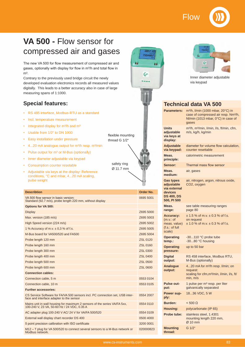
m³.Contrary to the previously used bridge circuit the newly developed evaluation electronics records all measured values digitally. This leads to a better accuracy also in case of large measuring spans of 1:1000.
Special features:RS 485 interface, Modbus-RTU as a standard
Incl. temperature measurement
Integrated display for m³/h and m³
Usable from 1/2“ to DN 1000
Easy installation under pressure
4...20 mA analogue output for m³/h resp. m³/min
Pulse output for m³ or M-Bus (optionally)
Inner diameter adjustable via keypad
Consumption counter resetable
Adjustable via keys at the display: Reference conditions, °C and mbar, 4...20 mA scaling, pulse weight
Inner diameter adjustable via keypad
thread G 1/2“
safety ringØ 11.7 mm
VA 500 - Flow sensor for compressed air and gases
Describtion Order No.
Standard (92.7 m/s), probe length 220 mm, without display0695 5001
Options for VA 500:
Display Z695 5000
Max. version (185 m/s) Z695 5003
High Speed version (224 m/s) Z695 5002
1 % Accuracy of m.v. ± 0,3 % of f.s. Z695 5005
M-Bus board for VA500/520 and FA500 Z695 5004
Probe length 120 mm ZSL 0120
Probe length 160 mm ZSL 0160
Probe length 300 mm ZSL 0300
Probe length 400 mm ZSL 0400
Probe length 500 mm ZSL 0500
Probe length 600 mm ZSL 0600
Connection cables:
Connection cable, 5 m 0553 0104
Connection cable, 10 m 0553 0105
Further accessories:
CS Service Software for FA/VA 500 sensors incl. PC connection set, USB inter-face and interface adapter to the sensor
0554 2007
Mains unit in wall housing for maximum 2 sensors of the series VA/FA 5xx,100-240 V, 23 VA, 50-60 Hz / 24 VDC, 0.35 A
0554 0110
AC adapter plug 100-240 V AC/ 24 V for VA/FA 500/520 0554 0109
External wall display chart recorder DS 400 0500 4000
3200 0001
M12 – T plug for VA 500/520 to connect several sensors to a M-Bus network or Modbus network.
020000823
Technical data VA 500Parameters: m³/h, l/min (1000 mbar, 20°C) in
case of compressed air resp. Nm³/h, Nl/min (1013 mbar, 0°C) in case of gases
Units adjustable via keys at display:
m³/h, m³/min, l/min, l/s, ft/min, cfm, m/s, kg/h, kg/min
Adjustable via keypad: counter resettable
Meas. principle:
calorimetric measurement
Sensor:Meas. medium:
air, gases
Gas types adjustable via external devices DS 400, DS 500, PI 500
air, nitrogen, argon, nitrous oxide, CO2, oxygen
Meas. range:
see table measuring ranges page 80
Accuracy: (m.v.: of meas. value)(f.s.: of full scale)
± 1.5 % of m.v. ± 0.3 % of f.s.on request± 1.0 % of m.v. ± 0.3 % of f.s.
Operating temp.:
-30...110 °C probe tube-30...80 °C housing
Operating pressure:
up to 50 bar
Digital output:
RS 458 interface, Modbus RTU,M-Bus (optionally)
Analogue output:
4...20 mA for m³/h resp. l/min; on request:scaling for cfm,m³/min, l/min, l/s, ft/min, m/s
Pulse out-put:
1 pulse per m³ resp. per liter galvanically separated
Power sup-ply:
18...36 VDC, 5 W
Burden:Housing: polycarbonate (IP 65)
Probe tube: stainless steel, 1.4301 mounting length 220 mm,Ø 10 mm
Mounting thread:
G 1/2“
Flow
83www.cs-instruments.com
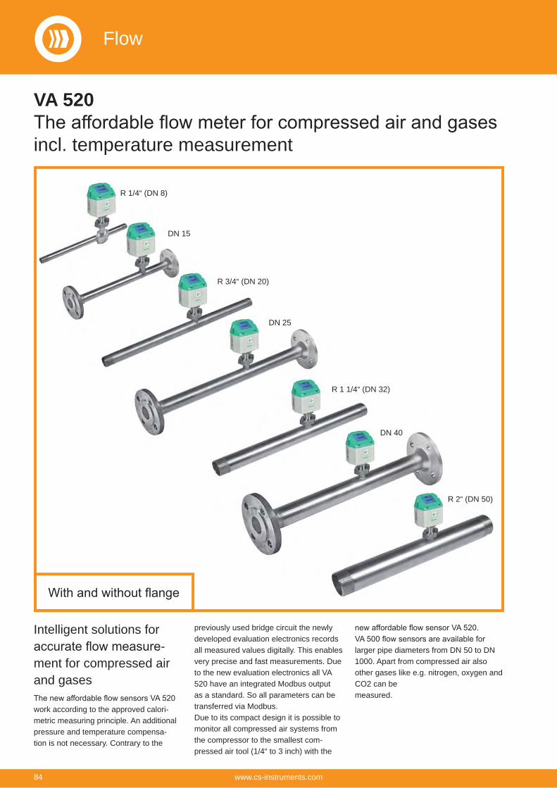
Intelligent solutions for -
ment for compressed air and gases
work according to the approved calori-metric measuring principle. An additional pressure and temperature compensa-tion is not necessary. Contrary to the
previously used bridge circuit the newly developed evaluation electronics records all measured values digitally. This enables very precise and fast measurements. Due to the new evaluation electronics all VA 520 have an integrated Modbus output as a standard. So all parameters can be transferred via Modbus.Due to its compact design it is possible to monitor all compressed air systems from the compressor to the smallest com-pressed air tool (1/4“ to 3 inch) with the
larger pipe diameters from DN 50 to DN 1000. Apart from compressed air also other gases like e.g. nitrogen, oxygen and CO2 can be measured.
R 1/4“ (DN 8)
DN 15
R 3/4“ (DN 20)
DN 25
R 1 1/4“ (DN 32)
DN 40
R 2“ (DN 50)
VA 520
incl. temperature measurement
Flow
84 www.cs-instruments.com
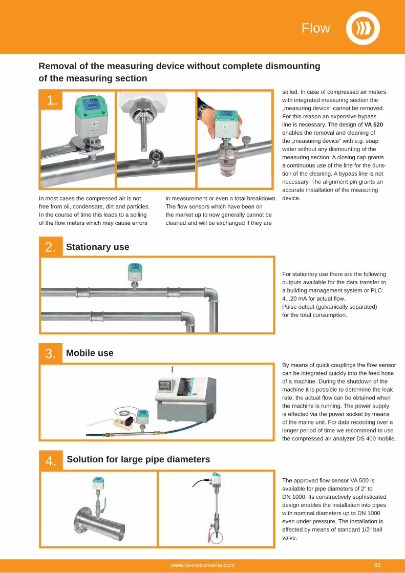
Removal of the measuring device without complete dismounting of the measuring section
In most cases the compressed air is not free from oil, condensate, dirt and particles. In the course of time this leads to a soiling
in measurement or even a total breakdown.
the market up to now generally cannot be cleaned and will be exchanged if they are
soiled. In case of compressed air meters with integrated measuring section the „measuring device“ cannot be removed. For this reason an expensive bypass line is necessary. The design of VA 520 enables the removal and cleaning of the „measuring device“ with e.g. soap water without any dismounting of the measuring section. A closing cap grants a continuous use of the line for the dura-tion of the cleaning. A bypass line is not necessary. The alignment pin grants an accurate installation of the measuring device.
Stationary use
For stationary use there are the following outputs available for the data transfer to a building management system or PLC:
Pulse output (galvanically separated) for the total consumption.
can be integrated quickly into the feed hose of a machine. During the shutdown of the machine it is possible to determine the leak
the machine is running. The power supply is effected via the power socket by means of the mains unit. For data recording over a longer period of time we recommend to use the compressed air analyzer DS 400 mobile.
available for pipe diameters of 2“ to DN 1000. Its constructively sophisticated design enables the installation into pipes with nominal diameters up to DN 1000 even under pressure. The installation is effected by means of standard 1/2“ ball valve.
Mobile use
Solution for large pipe diameters
1.
2.
3.
4.
Flow
85www.cs-instruments.com
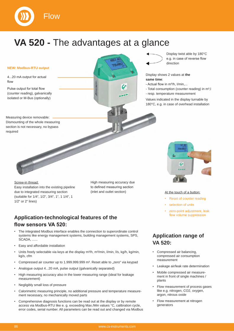
VA 520 - The advantages at a glance
Display shows 2 values at the same time:
- Total consumption (counter reading) in m³,l- resp. temperature measurement
Values indicated in the display turnable by 180°C, e.g. in case of overhead installation
4...20 mA output for actual
(counter reading), galvanically isolated or M-Bus (optionally)
Screw-in thread:Easy installation into the existing pipeline due to integrated measuring section (suitable for 1/4“, 1/2“, 3/4“, 1“, 1 1/4“, 1 1/2“ or 2“ lines)
High measuring accuracy due
(inlet and outlet section) At the touch of a button:
Reset of counter reading
selection of units
zero-point adjustment, leak
Application-technological features of the
The integrated Modbus interface enables the connection to superordinate control systems like energy management systems, building management systems, SPS, SCADA, ......
Easy and affordable installation
Units freely selectable via keys at the display m³/h, m³/min, l/min, l/s, kg/h, kg/min, kg/s, cfm
Compressed air counter up to 1.999.999.999 m³. Reset able to „zero“ via keypad
Analogue output 4...20 mA, pulse output (galvanically separated)
High measuring accuracy also in the lower measuring range (ideal for leakage measurement)
Negligibly small loss of pressure
Calorimetric measuring principle, no additional pressure and temperature measure-ment necessary, no mechanically moved parts
Comprehensive diagnosis functions can be read out at the display or by remote access via Modbus-RTU like e. g. exceeding Max./Min values °C, calibration cycle, error codes, serial number. All parameters can be read out and changed via Modbus
Application range ofVA 520:
Compressed air balancing, compressed air consumption measurement
Leakage air/leak rate determination
Mobile compressed air measure-ment in front of single machines / plants
Flow measurement of process gases like e.g. nitrogen, CO2, oxygen, argon, nitrous oxide
Flow measurement at nitrogen generators
Measuring device removable:Dismounting of the whole measuring section is not necessary, no bypass required
Display twist able by 180°C
directionNEW: Modbus-RTU output
Flow
86 www.cs-instruments.com
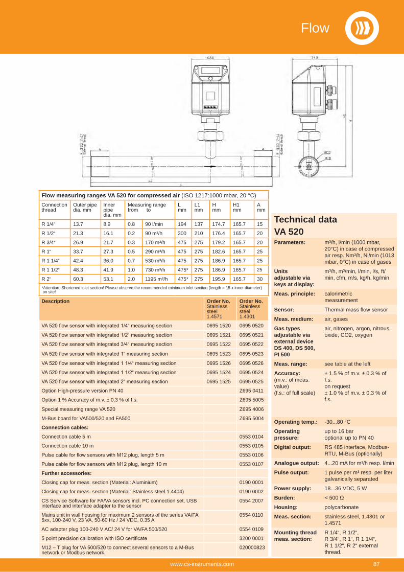
Description Order No.Stainless steel1.4571
Order No.Stainless steel1.4301
0695 1520 0695 0520
0695 1521 0695 0521
0695 1522 0695 0522
0695 1523 0695 0523
0695 1526 0695 0526
0695 1524 0695 0524
0695 1525 0695 0525
Option High-pressure version PN 40 Z695 0411
Option 1 % Accuracy of m.v. ± 0,3 % of f.s. Z695 5005
Special measuring range VA 520 Z695 4006
M-Bus board for VA500/520 and FA500 Z695 5004
Connection cables:
Connection cable 5 m 0553 0104
Connection cable 10 m 0553 0105
0553 0106
0553 0107
Further accessories:
Closing cap for meas. section (Material: Aluminium) 0190 0001
Closing cap for meas. section (Material: Stainless steel 1.4404) 0190 0002
CS Service Software for FA/VA sensors incl. PC connection set, USB interface and interface adapter to the sensor
0554 2007
Mains unit in wall housing for maximum 2 sensors of the series VA/FA 5xx, 100-240 V, 23 VA, 50-60 Hz / 24 VDC, 0.35 A
0554 0110
AC adapter plug 100-240 V AC/ 24 V for VA/FA 500/520 0554 0109
3200 0001
M12 – T plug for VA 500/520 to connect several sensors to a M-Bus network or Modbus network.
020000823
Flow measuring ranges VA 520 for compressed air (ISO 1217:1000 mbar, 20 °C)Connectionthread
Outer pipedia. mm
Inner pipe dia. mm
Measuring rangefrom to
Lmm
L1mm
Hmm
H1mm
Amm
R 1/4“ 13.7 8.9 0.8 90 l/min 194 137 174.7 165.7 15
R 1/2“ 21.3 16.1 0.2 90 m³/h 300 210 176.4 165.7 20
R 3/4“ 26.9 21.7 0.3 170 m³/h 475 275 179.2 165.7 20
R 1“ 33.7 27.3 0.5 290 m³/h 475 275 182.6 165.7 25
R 1 1/4“ 42.4 36.0 0.7 530 m³/h 475 275 186.9 165.7 25
R 1 1/2“ 48.3 41.9 1.0 730 m³/h 475* 275 186.9 165.7 25
R 2“ 60.3 53.1 2.0 1195 m³/h 475* 275 195.9 165.7 30*Attention: Shortened inlet section! Please observe the recommended minimum inlet section (length = 15 x inner diameter) on site!
Technical dataVA 520Parameters: m³/h, l/min (1000 mbar,
20°C) in case of compressed air resp. Nm³/h, Nl/min (1013 mbar, 0°C) in case of gases
Units adjustable via keys at display:
m³/h, m³/min, l/min, l/s, ft/min, cfm, m/s, kg/h, kg/min
Meas. principle: calorimetric measurement
Sensor:Meas. medium: air, gases
Gas types adjustable via external device DS 400, DS 500, PI 500
air, nitrogen, argon, nitrous oxide, CO2, oxygen
Meas. range: see table at the left
Accuracy: (m.v.: of meas. value)(f.s.: of full scale)
± 1.5 % of m.v. ± 0.3 % of f.s.on request± 1.0 % of m.v. ± 0.3 % of f.s.
Operating temp.: -30...80 °C
Operating pressure:
up to 16 baroptional up to PN 40
Digital output: RS 485 interface, Modbus-RTU, M-Bus (optionally)
Analogue output: 4...20 mA for m³/h resp. l/min
Pulse output: 1 pulse per m³ resp. per liter galvanically separated
Power supply: 18...36 VDC, 5 W
Burden:Housing: polycarbonate
Meas. section: stainless steel, 1.4301 or 1.4571
Mounting thread meas. section:
R 1/4“, R 1/2“,R 3/4“, R 1“, R 1 1/4“,R 1 1/2“, R 2“ external thread.
Flow
87www.cs-instruments.com
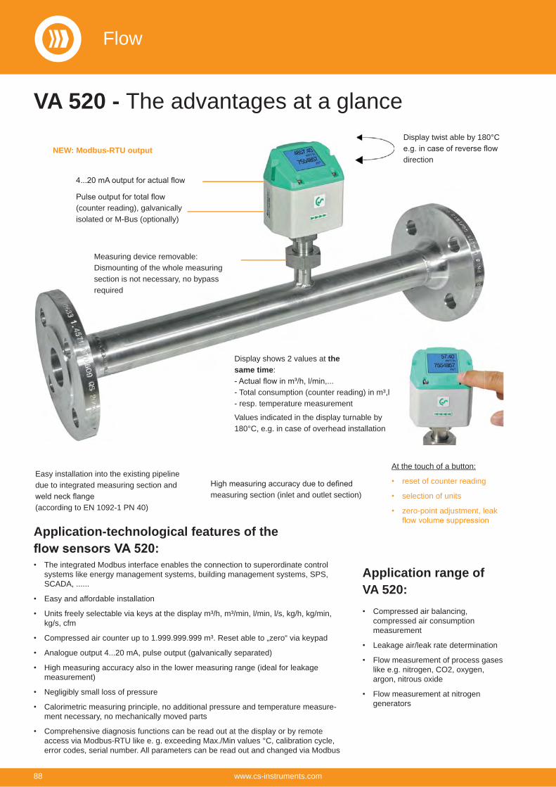
VA 520 - The advantages at a glance
Display shows 2 values at the same time:
- Total consumption (counter reading) in m³,l- resp. temperature measurement
Values indicated in the display turnable by 180°C, e.g. in case of overhead installation
(counter reading), galvanically isolated or M-Bus (optionally)
Easy installation into the existing pipeline due to integrated measuring section and
(according to EN 1092-1 PN 40)measuring section (inlet and outlet section)
At the touch of a button:
reset of counter reading
selection of units
zero-point adjustment, leak
Application-technological features of the
The integrated Modbus interface enables the connection to superordinate control systems like energy management systems, building management systems, SPS, SCADA, ......
Easy and affordable installation
Units freely selectable via keys at the display m³/h, m³/min, l/min, l/s, kg/h, kg/min, kg/s, cfm
Compressed air counter up to 1.999.999.999 m³. Reset able to „zero“ via keypad
Analogue output 4...20 mA, pulse output (galvanically separated)
High measuring accuracy also in the lower measuring range (ideal for leakage measurement)
Negligibly small loss of pressure
Calorimetric measuring principle, no additional pressure and temperature measure-ment necessary, no mechanically moved parts
Comprehensive diagnosis functions can be read out at the display or by remote access via Modbus-RTU like e. g. exceeding Max./Min values °C, calibration cycle, error codes, serial number. All parameters can be read out and changed via Modbus
Application range ofVA 520:
Compressed air balancing, compressed air consumption measurement
Leakage air/leak rate determination
Flow measurement of process gases like e.g. nitrogen, CO2, oxygen, argon, nitrous oxide
Flow measurement at nitrogen generators
Measuring device removable:Dismounting of the whole measuring section is not necessary, no bypass required
Display twist able by 180°C
directionNEW: Modbus-RTU output
Flow
88 www.cs-instruments.com
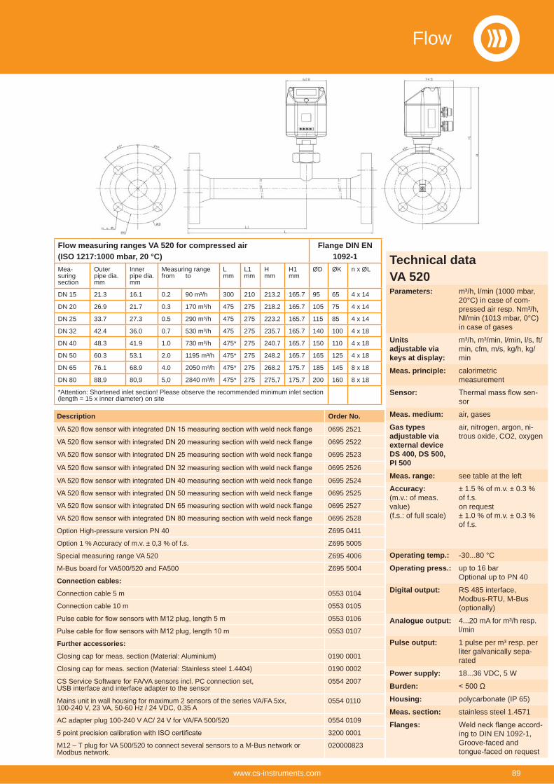
Description Order No.
0695 2521
0695 2522
0695 2523
0695 2526
0695 2524
0695 2525
0695 2527
0695 2528
Option High-pressure version PN 40 Z695 0411
Option 1 % Accuracy of m.v. ± 0,3 % of f.s. Z695 5005
Special measuring range VA 520 Z695 4006
M-Bus board for VA500/520 and FA500 Z695 5004
Connection cables:
Connection cable 5 m 0553 0104
Connection cable 10 m 0553 0105
0553 0106
0553 0107
Further accessories:
Closing cap for meas. section (Material: Aluminium) 0190 0001
Closing cap for meas. section (Material: Stainless steel 1.4404) 0190 0002
CS Service Software for FA/VA sensors incl. PC connection set, USB interface and interface adapter to the sensor
0554 2007
Mains unit in wall housing for maximum 2 sensors of the series VA/FA 5xx,100-240 V, 23 VA, 50-60 Hz / 24 VDC, 0.35 A
0554 0110
AC adapter plug 100-240 V AC/ 24 V for VA/FA 500/520 0554 0109
3200 0001
M12 – T plug for VA 500/520 to connect several sensors to a M-Bus network or Modbus network.
020000823
Flow measuring ranges VA 520 for compressed air (ISO 1217:1000 mbar, 20 °C)
Flange DIN EN 1092-1
Mea-suring section
Outer pipe dia. mm
Inner pipe dia. mm
Measuring rangefrom to
Lmm
L1mm
Hmm
H1mm
ØD ØK n x ØL
DN 15 21.3 16.1 0.2 90 m³/h 300 210 213.2 165.7 95 65 4 x 14
DN 20 26.9 21.7 0.3 170 m³/h 475 275 218.2 165.7 105 75 4 x 14
DN 25 33.7 27.3 0.5 290 m³/h 475 275 223.2 165.7 115 85 4 x 14
DN 32 42.4 36.0 0.7 530 m³/h 475 275 235.7 165.7 140 100 4 x 18
DN 40 48.3 41.9 1.0 730 m³/h 475* 275 240.7 165.7 150 110 4 x 18
DN 50 60.3 53.1 2.0 1195 m³/h 475* 275 248.2 165.7 165 125 4 x 18
DN 65 76.1 68.9 4.0 2050 m³/h 475* 275 268.2 175.7 185 145 8 x 18
DN 80 88,9 80,9 5,0 2840 m³/h 475* 275 275,7 175,7 200 160 8 x 18
*Attention: Shortened inlet section! Please observe the recommended minimum inlet section (length = 15 x inner diameter) on site
Technical dataVA 520Parameters: m³/h, l/min (1000 mbar,
20°C) in case of com-pressed air resp. Nm³/h, Nl/min (1013 mbar, 0°C) in case of gases
Units adjustable via keys at display:
m³/h, m³/min, l/min, l/s, ft/min, cfm, m/s, kg/h, kg/min
Meas. principle: calorimetricmeasurement
Sensor: -sor
Meas. medium: air, gases
Gas types adjustable via external device DS 400, DS 500, PI 500
air, nitrogen, argon, ni-trous oxide, CO2, oxygen
Meas. range: see table at the left
Accuracy: (m.v.: of meas. value)(f.s.: of full scale)
± 1.5 % of m.v. ± 0.3 % of f.s.on request± 1.0 % of m.v. ± 0.3 % of f.s.
Operating temp.: -30...80 °C
Operating press.: up to 16 barOptional up to PN 40
Digital output: RS 485 interface, Modbus-RTU, M-Bus (optionally)
Analogue output: 4...20 mA for m³/h resp. l/min
Pulse output: 1 pulse per m³ resp. per liter galvanically sepa-rated
Power supply: 18...36 VDC, 5 W
Burden:Housing: polycarbonate (IP 65)
Meas. section: stainless steel 1.4571
Flanges: -ing to DIN EN 1092-1, Groove-faced and tongue-faced on request
Flow
89www.cs-instruments.com
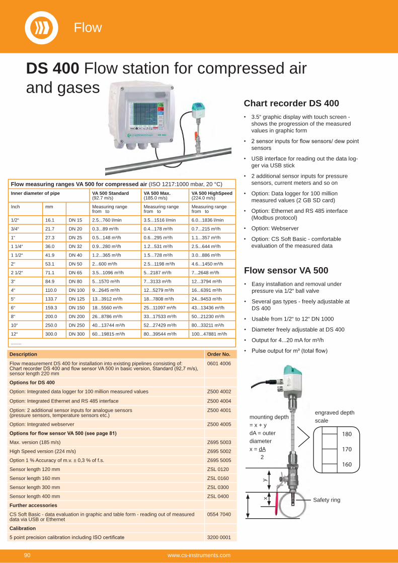
DS 400 Flow station for compressed airand gases
Description Order No.
Flow measurement DS 400 for installation into existing pipelines consisting of:
sensor length 220 mm
0601 4006
Options for DS 400
Option: Integrated data logger for 100 million measured values Z500 4002
Option: Integrated Ethernet and RS 485 interface Z500 4004
Option: 2 additional sensor inputs for analogue sensors(pressure sensors, temperature sensors etc.)
Z500 4001
Option: Integrated webserver Z500 4005
Max. version (185 m/s) Z695 5003
High Speed version (224 m/s) Z695 5002
Option 1 % Accuracy of m.v. ± 0,3 % of f.s. Z695 5005
Sensor length 120 mm ZSL 0120
Sensor length 160 mm ZSL 0160
Sensor length 300 mm ZSL 0300
Sensor length 400 mm ZSL 0400
Further accessories
CS Soft Basic - data evaluation in graphic and table form - reading out of measured data via USB or Ethernet
0554 7040
Calibration
3200 0001
Flow measuring ranges VA 500 for compressed air (ISO 1217:1000 mbar, 20 °C)Inner diameter of pipe VA 500 Standard
(92.7 m/s)VA 500 Max.(185.0 m/s)
VA 500 HighSpeed(224.0 m/s)
Inch mm Measuring rangefrom to
Measuring rangefrom to
Measuring rangefrom to
1/2“ 16.1 DN 15 2.5...760 l/min 3.5...1516 l/min 6.0...1836 l/min
3/4“ 21.7 DN 20 0.3...89 m³/h 0.4...178 m³/h 0.7...215 m³/h
1“ 27.3 DN 25 0.5...148 m³/h 0.6...295 m³/h 1.1...357 m³/h
1 1/4“ 36.0 DN 32 0.9...280 m³/h 1.2...531 m³/h 2.5...644 m³/h
1 1/2“ 41.9 DN 40 1.2...365 m³/h 1.5...728 m³/h 3.0...886 m³/h
2“ 53.1 DN 50 2...600 m³/h 2.5...1198 m³/h 4.6...1450 m³/h
2 1/2“ 71.1 DN 65 3.5...1096 m³/h 5...2187 m³/h 7...2648 m³/h
3“ 84.9 DN 80 5...1570 m³/h 7...3133 m³/h 12...3794 m³/h
4“ 110.0 DN 100 9...2645 m³/h 12...5279 m³/h 16...6391 m³/h
5“ 133.7 DN 125 13...3912 m³/h 18...7808 m³/h 24...9453 m³/h
6“ 159.3 DN 150 18...5560 m³/h 25...11097 m³/h 43...13436 m³/h
8“ 200.0 DN 200 26...8786 m³/h 33...17533 m³/h 50...21230 m³/h
10“ 250.0 DN 250 40...13744 m³/h 52...27429 m³/h 80...33211 m³/h
12“ 300.0 DN 300 60...19815 m³/h 80...39544 m³/h 100...47881 m³/h
........
Chart recorder DS 4003.5“ graphic display with touch screen - shows the progression of the measured values in graphic form
sensors
USB interface for reading out the data log-ger via USB stick
2 additional sensor inputs for pressure sensors, current meters and so on
Option: Data logger for 100 million measured values (2 GB SD card)
Option: Ethernet and RS 485 interface (Modbus protocol)
Option: Webserver
Option: CS Soft Basic - comfortable evaluation of the measured data
Flow sensor VA 500Easy installation and removal under pressure via 1/2“ ball valve
Several gas types - freely adjustable at DS 400
Usable from 1/2“ to 12“ DN 1000
Diameter freely adjustable at DS 400
Output for 4...20 mA for m³/h
mounting depth = x + ydA = outer diameterx = dA 2
yx
180
170
160
engraved depth scale
Safety ring
Flow
90 www.cs-instruments.com
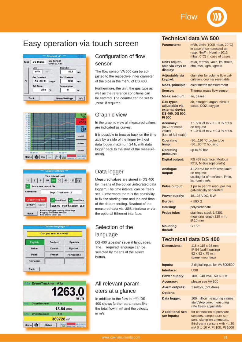
Easy operation via touch screen
sensor-
justed to the respective inner diameter of the pipe in the menu of DS 400.
Furthermore, the unit, the gas type as well as the reference conditions can be entered. The counter can be set to „zero“ if required.
Graphic viewIn the graphic view all measured values are indicated as curves.
It is possible to browse back on the time
data logger maximum 24 h, with data logger back to the start of the measure-ment).
Data loggerMeasured values are stored in DS 400 by means of the option „integrated data logger“. The time interval can be freely set. Furthermore there is the possibility
of the data recording. Readout of the measured data via USB interface or via the optional Ethernet interface.
Selection of the languageDS 400 „speaks“ several languages. The required language can be selected by means of the select button.
All relevant param-eters at a glance
400 shows further parameters like
in m/s.
Technical data DS 400Dimensions: 118 x 115 x 98 mm
IP 54 (wall housing)92 x 92 x 75 mm(panel mounting)
Inputs: 2 digital inputs for VA 500/520
Interface: USB
Power supply: 100...240 VAC, 50-60 Hz
Accuracy: please see VA 500
Alarm outputs: 2 relays, (pot.-free)
Options:Data logger: 100 million measuring values
start/stop time, measuring rate freely adjustable
2 additional sen-sor inputs:
for connection of pressure sensors, temperature sen-sors, clamp-on ammeters, third-party sensors with 4...20 mA 0 to 10 V, Pt 100, Pt 1000
Technical data VA 500Parameters: m³/h, l/min (1000 mbar, 20°C)
in case of compressed air resp. Nm³/h, Nl/min (1013 mbar, 0°C) in case of gases
Units adjust-able via keys at display:
m³/h, m³/min, l/min, l/s, ft/min, cfm, m/s, kg/h, kg/min
Adjustable via keypad:
-culation, counter resettable
Meas. principle: calorimetric measurement
Sensor:Meas. medium: air, gases
Gas types adjustable via external device DS 400, DS 500, PI 500
air, nitrogen, argon, nitrous oxide, CO2, oxygen
Accuracy: (m.v.: of meas. value)(f.s.: of full scale)
± 1.5 % of m.v. ± 0.3 % of f.s.on request± 1.0 % of m.v. ± 0.3 % of f.s.
Operating temp.:
-30...110 °C probe tube-30...80 °C housing
Operating pressure:
up to 50 bar
Digital output: RS 458 interface, Modbus RTU, M-Bus (optionally)
Analogue output:
4...20 mA for m³/h resp.l/min; on request:scaling for cfm,m³/min, l/min, l/s, ft/min, m/s
Pulse output: 1 pulse per m³ resp. per liter galvanically separated
Power supply: 18...36 VDC, 5 W
Burden:Housing: polycarbonate
Probe tube: stainless steel, 1.4301 mounting length 220 mm,Ø 10 mm
Mounting thread:
G 1/2“
Flow
91www.cs-instruments.com
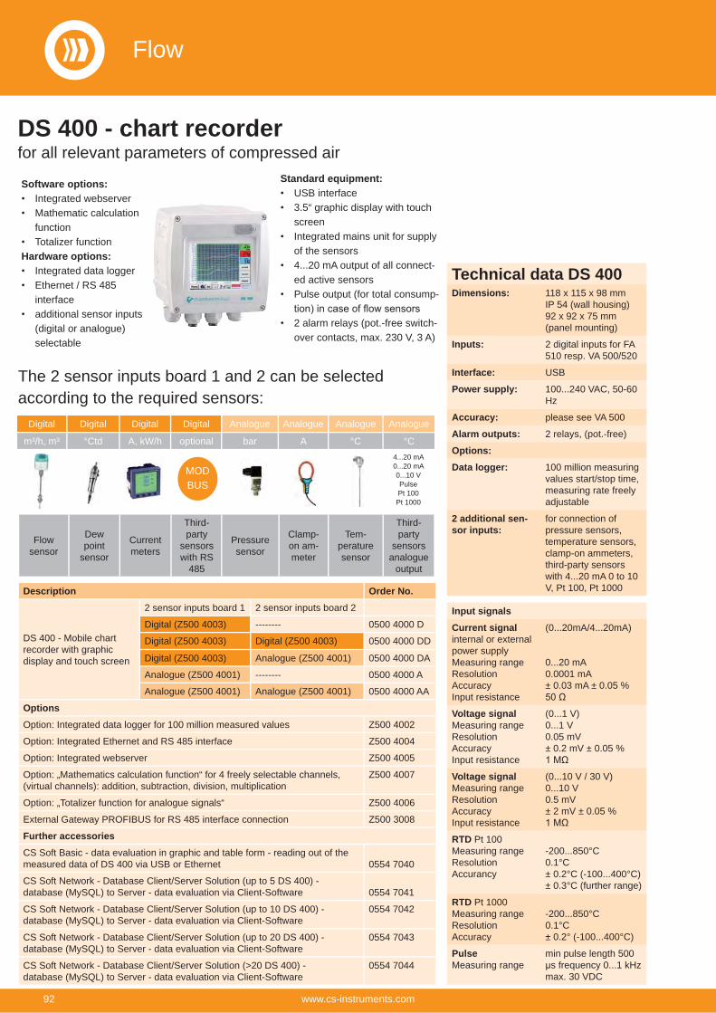
Description Order No.
DS 400 - Mobile chart recorder with graphic display and touch screen
2 sensor inputs board 1 2 sensor inputs board 2
Digital (Z500 4003) -------- 0500 4000 D
Digital (Z500 4003) Digital (Z500 4003) 0500 4000 DD
Digital (Z500 4003) Analogue (Z500 4001) 0500 4000 DA
Analogue (Z500 4001) -------- 0500 4000 A
Analogue (Z500 4001) Analogue (Z500 4001) 0500 4000 AA
OptionsOption: Integrated data logger for 100 million measured values Z500 4002
Option: Integrated Ethernet and RS 485 interface Z500 4004
Option: Integrated webserver Z500 4005
Option: „Mathematics calculation function“ for 4 freely selectable channels, (virtual channels): addition, subtraction, division, multiplication
Z500 4007
Option: „Totalizer function for analogue signals“ Z500 4006
External Gateway PROFIBUS for RS 485 interface connection Z500 3008
Further accessoriesCS Soft Basic - data evaluation in graphic and table form - reading out of the measured data of DS 400 via USB or Ethernet 0554 7040
CS Soft Network - Database Client/Server Solution (up to 5 DS 400) - database (MySQL) to Server - data evaluation via Client-Software 0554 7041
CS Soft Network - Database Client/Server Solution (up to 10 DS 400) - database (MySQL) to Server - data evaluation via Client-Software
0554 7042
CS Soft Network - Database Client/Server Solution (up to 20 DS 400) - database (MySQL) to Server - data evaluation via Client-Software
0554 7043
CS Soft Network - Database Client/Server Solution (>20 DS 400) - database (MySQL) to Server - data evaluation via Client-Software
0554 7044
Digital Digital Digital Digital
m³/h, m³ °Ctd A, kW/h optional
MODBUS
Flow sensor
Dew point
sensor
Current meters
Third-party
sensors with RS
485
Analogue Analogue Analogue Analogue
bar A °C °C
Pressure sensor
Clamp-on am-meter
Tem-perature sensor
Third-party
sensors analogue
output
4...20 mA 0...20 mA0...10 VPulsePt 100Pt 1000
DS 400 - chart recorderfor all relevant parameters of compressed air
Software options:Integrated webserverMathematic calculation functionTotalizer function
Hardware options:Integrated data loggerEthernet / RS 485 interfaceadditional sensor inputs (digital or analogue) selectable
Standard equipment:USB interface3.5“ graphic display with touch screenIntegrated mains unit for supply of the sensors4...20 mA output of all connect-ed active sensorsPulse output (for total consump-
2 alarm relays (pot.-free switch-over contacts, max. 230 V, 3 A)
The 2 sensor inputs board 1 and 2 can be selected according to the required sensors:
Input signalsCurrent signalinternal or external power supplyMeasuring rangeResolutionAccuracyInput resistance
(0...20mA/4...20mA)
0...20 mA0.0001 mA± 0.03 mA ± 0.05 %
Voltage signalMeasuring rangeResolutionAccuracyInput resistance
(0...1 V)0...1 V0.05 mV± 0.2 mV ± 0.05 %
Voltage signalMeasuring rangeResolutionAccuracyInput resistance
(0...10 V / 30 V)0...10 V0.5 mV± 2 mV ± 0.05 %
RTD Pt 100Measuring rangeResolutionAccurancy
-200...850°C0.1°C± 0.2°C (-100...400°C)± 0.3°C (further range)
RTD Pt 1000Measuring rangeResolutionAccuracy
-200...850°C0.1°C± 0.2° (-100...400°C)
PulseMeasuring range
min pulse length 500 μs frequency 0...1 kHzmax. 30 VDC
Technical data DS 400Dimensions: 118 x 115 x 98 mm
IP 54 (wall housing)92 x 92 x 75 mm(panel mounting)
Inputs: 2 digital inputs for FA 510 resp. VA 500/520
Interface: USB
Power supply: 100...240 VAC, 50-60 Hz
Accuracy: please see VA 500
Alarm outputs: 2 relays, (pot.-free)
Options:Data logger: 100 million measuring
values start/stop time, measuring rate freely adjustable
2 additional sen-sor inputs:
for connection of pressure sensors, temperature sensors, clamp-on ammeters, third-party sensors with 4...20 mA 0 to 10 V, Pt 100, Pt 1000
Flow
92 www.cs-instruments.com
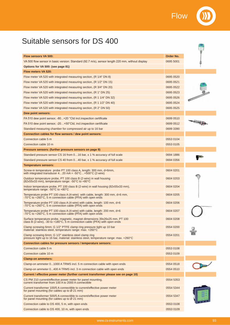
Suitable sensors for DS 400
Flow sensors VA 500: Order No.
0695 5001
Options for VA 500: (see page 81)Flow meters VA 520:
Flow meter VA 520 with integrated measuring section, (R 1/4“ DN 8) 0695 0520
Flow meter VA 520 with integrated measuring section, (R 1/2“ DN 15) 0695 0521
Flow meter VA 520 with integrated measuring section, (R 3/4“ DN 20) 0695 0522
Flow meter VA 520 with integrated measuring section, (R 1“ DN 25) 0695 0523
Flow meter VA 520 with integrated measuring section, (R 1 1/4“ DN 32) 0695 0526
Flow meter VA 520 with integrated measuring section, (R 1 1/2“ DN 40) 0695 0524
Flow meter VA 520 with integrated measuring section, (R 2“ DN 50) 0695 0525
Dew point sensors:
0699 0510
0699 0512
Standard measuring chamber for compressed air up to 16 bar 0699 3390
Connection cable 5 m 0553 0104
Connection cable 10 m 0553 0105
Pressure sensors: (further pressure sensors on page 9)
Standard pressure sensor CS 16 from 0…16 bar, ± 1 % accuracy of full scale 0694 1886
Standard pressure sensor CS 40 from 0…40 bar, ± 1 % accuracy of full scale 0694 0356
Temperature sensors:
Screw-in temperature probe PT 100 class A, length: 300 mm, d=6mm,with integrated transducer 4…20 mA = -50°C…+500°C (2-wire)
0604 0201
Outdoor temperature probe, PT 100 class B (2-wire) in wall housing(82x55x33 mm), temperature range: -50°C to +80°C
0604 0203
Indoor temperature probe, PT 100 class B (2-wire) in wall housing (82x55x33 mm),temperature range: -50°C to +80°C
0604 0204
Temperature probe PT 100 class A (4-wire) with cable, length: 300 mm, d=6 mm,-70°C to +260°C, 5 m connection cable (PFA) with open ends
0604 0205
Temperature probe PT 100 class A (4-wire) with cable, length: 100 mm, d=6-70°C to +260°C, 5 m connection cable (PFA) with open ends
0604 0206
Temperature probe PT 100 class A (4-wire) with cable, length: 200 mm, d=6-70°C to +260°C, 5 m connection cable (PFA) with open ends
0604 0207
Surface temperature probe, magnetic, magnet dimensions 39x26x25 mm, PT 100class B (2-wire), -30 to +180°C, 5 m connection cable (PFA) with open ends
0604 0208
Clamp screwing 6mm; G 1/2“ PTFE clamp ring pressure tight up 10 barmaterial: stainless steel, temperature range: max. +260°C
0554 0200
Clamp screwing 6mm; G 1/2“ stainless steel clamp ringpressure tight up to 16 bar, material: stainless steel, temperature range: max. +260°C
0554 0201
Connection cables for pressure sensors / temperature sensors:
Connection cable 5 m 0553 0108
Connection cable 10 m 0553 0109
Clamp-on ammeters:
Clamp-on ammeter 0...1000 A TRMS incl. 5 m connection cable with open ends 0554 0518
Clamp-on ammeter 0...400 A TRMS incl. 3 m connection cable with open ends 0554 0510
Current / effective power meter (further current transformer please see on page 10)
CS PM 210 current/effective power meter for panel mounting, current transformer from 100 A to 2000 A connectible
0554 5353
Current transformer 100/5 A connectible to current/effective power meter for panel mounting (for cables up to Ø 21 mm)
0554 5344
Current transformer 500/5 A connectible to current/effective power meter for panel mounting (for cables up to Ø 21 mm)
0554 5347
Connection cable to DS 400, 5 m, with open ends 0553 0108
Connection cable to DS 400, 10 m, with open ends 0553 0109
Flow
93www.cs-instruments.com
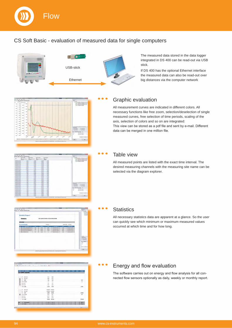
CS Soft Basic - evaluation of measured data for single computers
Graphic evaluationAll measurement curves are indicated in different colors. All necessary functions like free zoom, selection/deselection of single measured curves, free selection of time periods, scaling of the axis, selection of colors and so on are integrated:
Table viewAll measured points are listed with the exact time interval. The desired measuring channels with the measuring site name can be selected via the diagram explorer.
StatisticsAll necessary statistics data are apparent at a glance. So the user can quickly see which minimum or maximum measured values occurred at which time and for how long.
-
Ethernet
USB-stick
The measured data stored in the data logger integrated in DS 400 can be read-out via USB stick.
If DS 400 has the optional Ethernet interface the measured data can also be read-out over big distances via the computer network
Flow
94 www.cs-instruments.com

Client
CS Soft Network - evaluation of the measured data for several computers in the networkBy means of the CS Soft Network an optional number of DS 500/ DS 400 in-struments can be evaluated via Ethernet. The software stores the measured data of all DS 500 / DS 400 cyclically (cycle freely selectable) in a SQL database on
the server. In case of an exceeding of the stored alarm values the software automat-ically sends an SMS or an e-mail. Further-
in the server software so that single staff members only can access the measured
data of certain DS 500 / DS 400.
The evaluation of the measured data can be carried out by means of the client soft-ware from each PC within the company.
SERVER
ETHERNET
WORLD WIDE WEB
Functions of the CS Soft Network (Server):
Automatic data storage in My SQL data-base (cycle freely programmable)
User administration
-sion via SMS/e-mail
Functions of the CS Soft Network (Client):
Indication of current measured values
Graphical chart with zoom function
In table form
Report generation (standard report with Min-Max values, number of alarm ex-ceedings, moment of alarm exceeding)
Automatic consumption report
WORLD WIDE WEB With the option „Webserver“ (order no. Z500 4005) DS 400 can be contacted without any special software from each web browser (eg. Mozilla Firefox ®, Microsoft Internet Explorer ®).
The access can also be done via the World Wide Web. The webserver indicates the actual measured values of all sensors as well as the status of the alarm relays and the logger status in the web browser.
With the option „Ethernet / RS 485 - interface“ (order no. Z500 4004) DS 400 can be connected to customer-owned Bus system (e.g. PLC, building management system BMS, central control system, SCADA,...).
The measured values of all sensors can be retrieved via Modbus protocol. A detailed protocol description is enclosed with each DS 400 instrument. When using the Ethernet interface the IP address at DS 400 can be freely adjusted. As an alternative DS 400 waits for the address allocation by a DHCP server.RS 485 network (Modbus RTU)
or Ethernet (Modbus/TCP)
Access to the measured values via the webserver
Connection to Bus system
Client Client
Ethernet
Flow
95www.cs-instruments.com
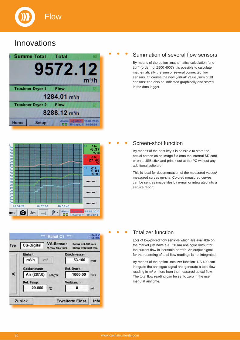
Totalizer function
the market just have a 4...20 mA analogue output for
By means of the option „totalizer function“ DS 400 can
menu at any time.
By means of the option „mathematics calculation func-tion“ (order no. Z500 4007) it is possible to calculate
sensors. Of course the new „virtual“ value „sum of all sensors“ can also be indicated graphically and stored in the data logger.
Screen-shot functionBy means of the print key it is possible to store the
or on a USB stick and print it out at the PC without any additional software.
This is ideal for documentation of the measured values/ measured curves on-site. Colored measured curves
service report.
Innovations
Flow
96 www.cs-instruments.com
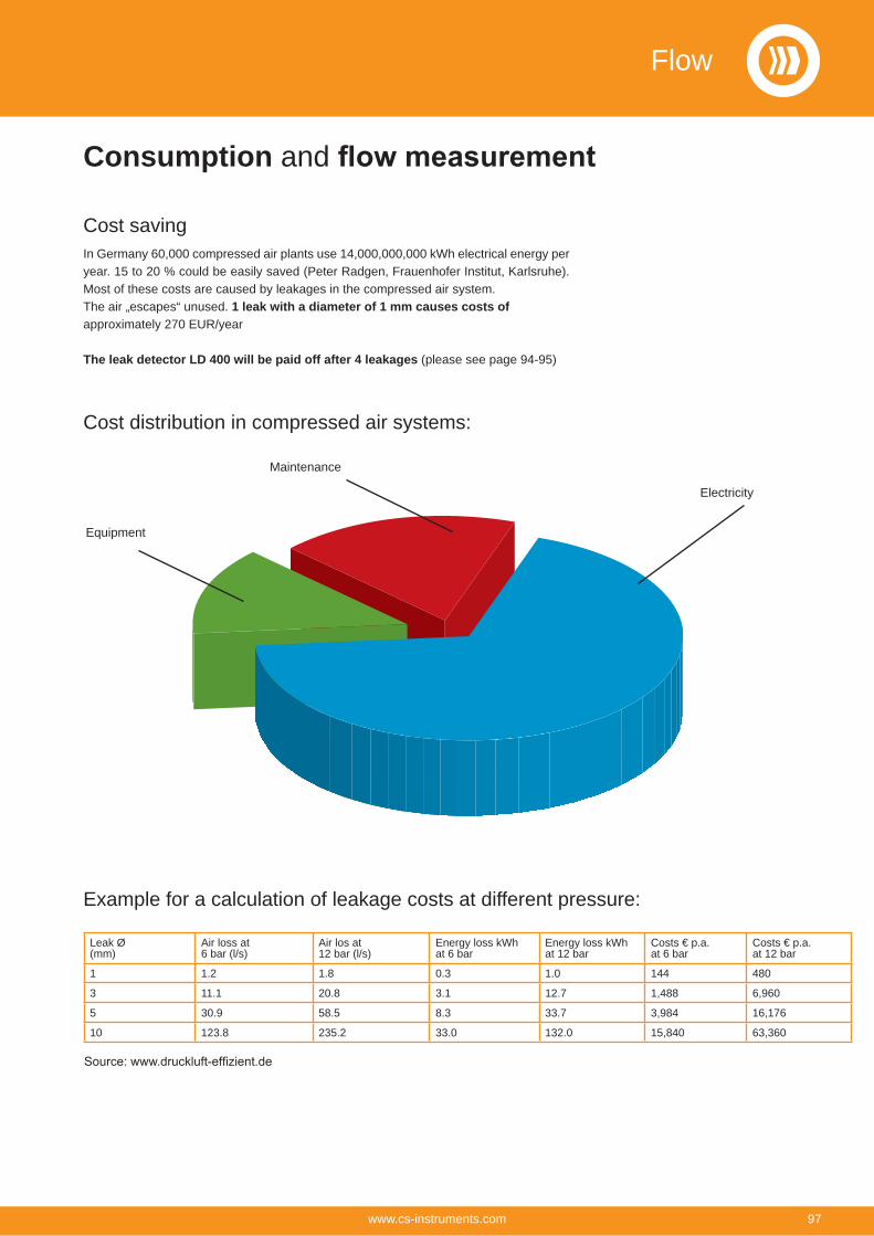
Cost savingIn Germany 60,000 compressed air plants use 14,000,000,000 kWh electrical energy per year. 15 to 20 % could be easily saved (Peter Radgen, Frauenhofer Institut, Karlsruhe). Most of these costs are caused by leakages in the compressed air system.The air „escapes“ unused. 1 leak with a diameter of 1 mm causes costs of approximately 270 EUR/year
The leak detector LD 400 will be paid off after 4 leakages (please see page 94-95)
Cost distribution in compressed air systems:
Equipment
Maintenance
Electricity
Consumption and
Example for a calculation of leakage costs at different pressure:
Leak Ø(mm)
Air loss at 6 bar (l/s)
Air los at 12 bar (l/s)
Energy loss kWhat 6 bar
Energy loss kWhat 12 bar
Costs € p.a.at 6 bar
Costs € p.a.at 12 bar
1 1.2 1.8 0.3 1.0 144 480
3 11.1 20.8 3.1 12.7 1,488 6,960
5 30.9 58.5 8.3 33.7 3,984 16,176
10 123.8 235.2 33.0 132.0 15,840 63,360
Flow
97www.cs-instruments.com
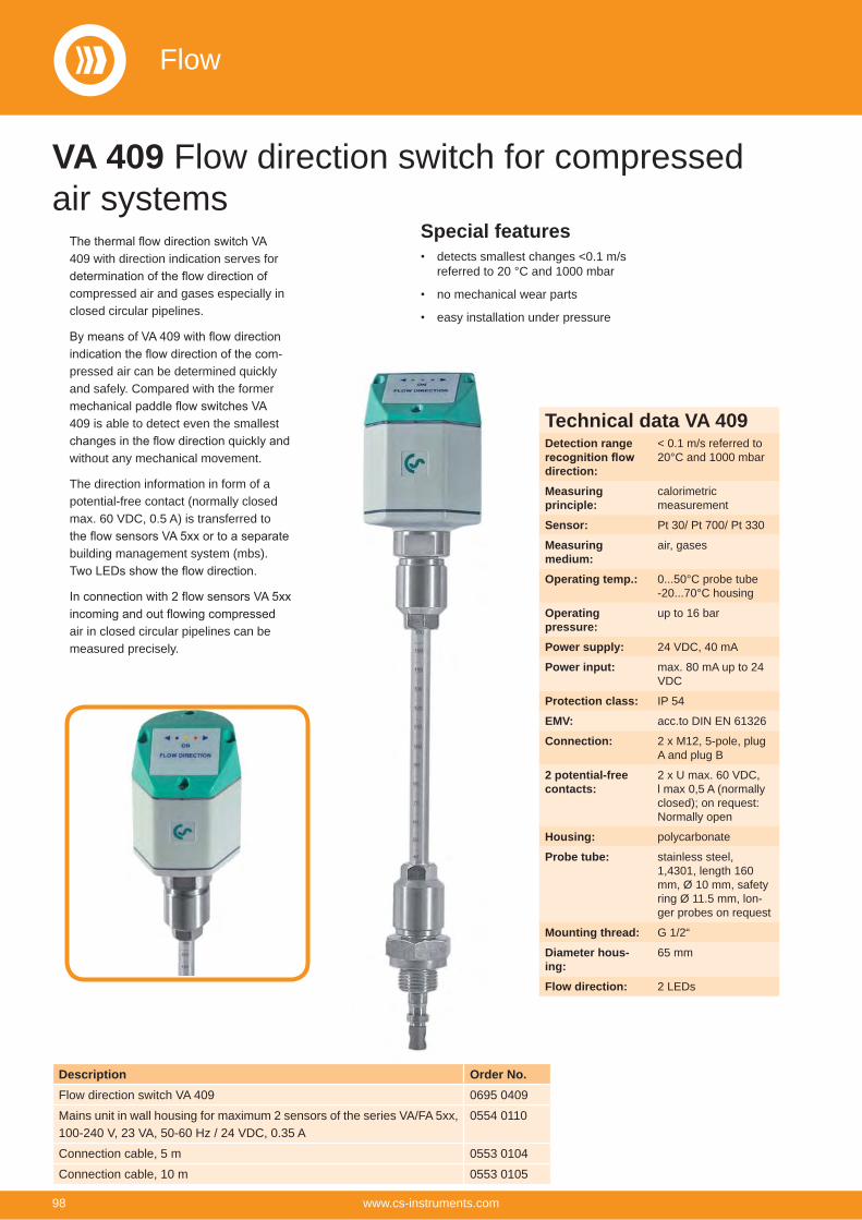
VA 409 Flow direction switch for compressed air systems
Description Order No.Flow direction switch VA 409 0695 0409
Mains unit in wall housing for maximum 2 sensors of the series VA/FA 5xx,100-240 V, 23 VA, 50-60 Hz / 24 VDC, 0.35 A
0554 0110
Connection cable, 5 m 0553 0104
Connection cable, 10 m 0553 0105
409 with direction indication serves for
compressed air and gases especially in closed circular pipelines.
-pressed air can be determined quickly and safely. Compared with the former
409 is able to detect even the smallest
without any mechanical movement.
The direction information in form of a potential-free contact (normally closed max. 60 VDC, 0.5 A) is transferred to
building management system (mbs).
air in closed circular pipelines can be measured precisely.
Special featuresdetects smallest changes <0.1 m/s referred to 20 °C and 1000 mbar
no mechanical wear parts
easy installation under pressure
Technical data VA 409Detection range
direction:
< 0.1 m/s referred to 20°C and 1000 mbar
Measuring principle:
calorimetricmeasurement
Sensor: Pt 30/ Pt 700/ Pt 330
Measuringmedium:
air, gases
Operating temp.: 0...50°C probe tube-20...70°C housing
Operatingpressure:
up to 16 bar
Power supply: 24 VDC, 40 mA
Power input: max. 80 mA up to 24 VDC
Protection class: IP 54
EMV: acc.to DIN EN 61326
Connection: 2 x M12, 5-pole, plug A and plug B
2 potential-free contacts:
2 x U max. 60 VDC, l max 0,5 A (normally closed); on request: Normally open
Housing: polycarbonate
Probe tube: stainless steel, 1,4301, length 160 mm, Ø 10 mm, safety ring Ø 11.5 mm, lon-ger probes on request
Mounting thread: G 1/2“
Diameter hous-ing:
65 mm
Flow direction: 2 LEDs
Flow
98 www.cs-instruments.com
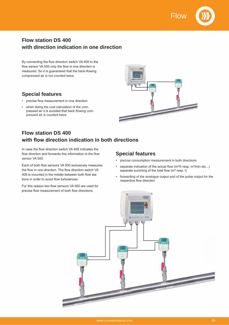
Flow station DS 400with direction indication in one direction
compressed air is not counted twice.
Special features
when doing the cost calculation of the com--
pressed air is counted twice
Flow station DS 400
sensor VA 500.
-
Special featuresprecise consumption measurement in both directions
forwarding of the analogue output and of the pulse output for the
Flow
99www.cs-instruments.com
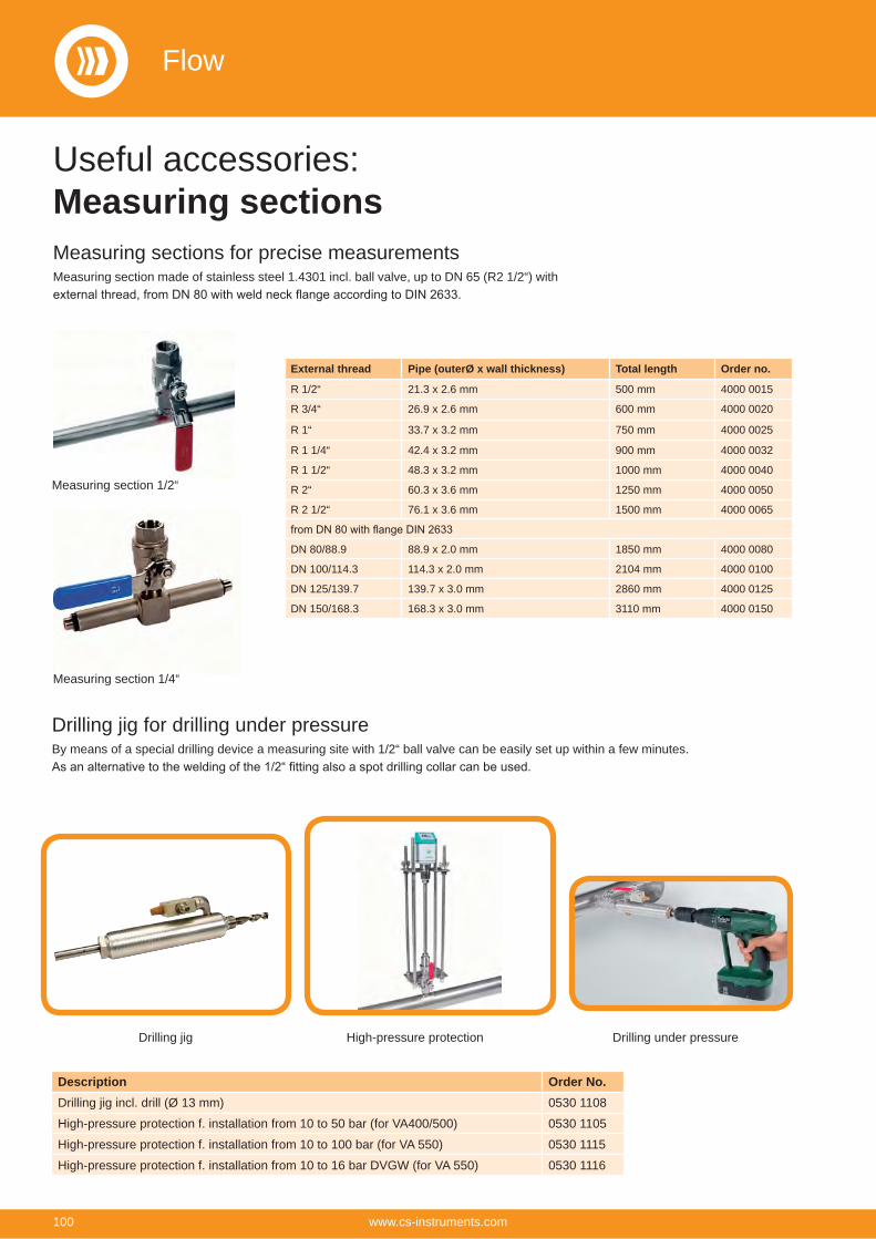
Useful accessories:Measuring sections
Measuring section 1/2“
Measuring section 1/4“
Measuring sections for precise measurementsMeasuring section made of stainless steel 1.4301 incl. ball valve, up to DN 65 (R2 1/2“) with
Drilling jig for drilling under pressureBy means of a special drilling device a measuring site with 1/2“ ball valve can be easily set up within a few minutes.
Drilling jig High-pressure protection Drilling under pressure
Description Order No.Drilling jig incl. drill (Ø 13 mm) 0530 1108
High-pressure protection f. installation from 10 to 50 bar (for VA400/500) 0530 1105
High-pressure protection f. installation from 10 to 100 bar (for VA 550) 0530 1115
High-pressure protection f. installation from 10 to 16 bar DVGW (for VA 550) 0530 1116
External thread Pipe (outerØ x wall thickness) Total length Order no.
R 1/2“ 21.3 x 2.6 mm 500 mm 4000 0015
R 3/4“ 26.9 x 2.6 mm 600 mm 4000 0020
R 1“ 33.7 x 3.2 mm 750 mm 4000 0025
R 1 1/4“ 42.4 x 3.2 mm 900 mm 4000 0032
R 1 1/2“ 48.3 x 3.2 mm 1000 mm 4000 0040
R 2“ 60.3 x 3.6 mm 1250 mm 4000 0050
R 2 1/2“ 76.1 x 3.6 mm 1500 mm 4000 0065
DN 80/88.9 88.9 x 2.0 mm 1850 mm 4000 0080
DN 100/114.3 114.3 x 2.0 mm 2104 mm 4000 0100
DN 125/139.7 139.7 x 3.0 mm 2860 mm 4000 0125
DN 150/168.3 168.3 x 3.0 mm 3110 mm 4000 0150
Flow
100 www.cs-instruments.com

Useful accessories:Spot drilling collars for compressed air pipesIf there is no measuring site with 1/2“ ball valve present it can be set up by means of spot drilling collars.
The spot drilling collar is imposed onto the pipe and tightened via thread rods. The enveloping rubber gasket is pressure-tight up to 10 bar. By means of the drilling jig it is possible to drill through the 1/2“ ball valve into the existing pipe.
Important: Please indicate the exact outer diameter of the existing pipe when placing the order resp. please select the suitable spot drilling collar from the adjoining list.
Spot drilling collar
Thickness meterCS 0495
Description Order No.Thickness meter CS 0495 including case and calibration block 0560 0495
The entry of the correct inner diameter is es-sential for an accurate consumption measurement.
The thickness meter CS 0495 enables a quick, easy and accurate measurement of the wall thickness of pipes. So the determination of the inner diameter becomes very easy.
*inkl. 1/2“ ball valve*not applicable for copper and plastic piping
Description DN Order no.Spot drilling collar for pipe Ø 032 - 036 mm, Length: 100 mm* 0500 0446
Spot drilling collar for pipe Ø 036 - 040 mm, Length: 100 mm* 0500 0448
Spot drilling collar for pipe Ø 040 - 044 mm, Length: 150 mm* 0500 0449
Spot drilling collar for pipe Ø 044 - 051 mm, Length: 200 mm* 0500 0610
Spot drilling collar for pipe Ø 048 - 055 mm, Length: 200 mm* 40 0500 0611
Spot drilling collar for pipe Ø 052 - 059 mm, Length: 200 mm* 0500 0612
Spot drilling collar for pipe Ø 057 - 064 mm, Length: 200 mm* 50 0500 0613
Spot drilling collar for pipe Ø 063 - 070 mm, Length: 200 mm* 0500 0614
Spot drilling collar for pipe Ø 070 - 077 mm, Length: 200 mm* 65 0500 0615
Spot drilling collar for pipe Ø 075 - 083 mm, Length: 200 mm* 0500 0616
Spot drilling collar for pipe Ø 082 - 090 mm, Length: 200 mm* 0500 0617
Spot drilling collar for pipe Ø 087 - 097 mm, Length: 200 mm* 80 0500 0618
Spot drilling collar for pipe Ø 095 - 104 mm, Length: 200 mm* 0500 0619
Spot drilling collar for pipe Ø 102 - 112 mm, Length: 200 mm* 0500 0620
Spot drilling collar for pipe Ø 108 - 118 mm, Length: 200 mm* 100 0500 0621
Spot drilling collar for pipe Ø 118 - 128 mm, Length: 200 mm* 0500 0622
Spot drilling collar for pipe Ø 125 - 135 mm, Length: 200 mm* 0500 0623
Spot drilling collar for pipe Ø 133 - 144 mm, Length: 200 mm* 125 0500 0624
Spot drilling collar for pipe Ø 145 - 155 mm, Length: 250 mm* 0500 0625
Spot drilling collar for pipe Ø 151 - 161 mm, Length: 250 mm* 150 0500 0626
Spot drilling collar for pipe Ø 159 - 170 mm, Length: 250 mm* 0500 0627
Spot drilling collar for pipe Ø 168 - 180 mm, Length: 250 mm* 0500 0628
Spot drilling collar for pipe Ø 180 - 191 mm, Length: 250 mm* 175 0500 0629
Spot drilling collar for pipe Ø 193 - 203 mm, Length: 300 mm* 0500 0630
Spot drilling collar for pipe Ø 200 - 210 mm, Length: 300 mm* 0500 0631
Spot drilling collar for pipe Ø 209 - 220 mm, Length: 300 mm* 200 0500 0632
Technical data CS 0495Meas. range: 1.5...200 mm, 0.06...8
Inch
Meas. principle: ultrasonic
Measuredmaterials:
steel, cast iron, aluminium, copper, brass, zinc, quartz glass, polyethylene, PVC, grey iron, nodu-lar cast iron
Calibration block:
included in shipment
Resolution: 0.1 mm
Accuracy: ± (0.5 % n+ 0.1)
Power supply: 4 x 1.5 V AA (UM-3) batteries
Dimensions: 160 x 68 x 32 mm
Weight: 208 g
Flow
101www.cs-instruments.com
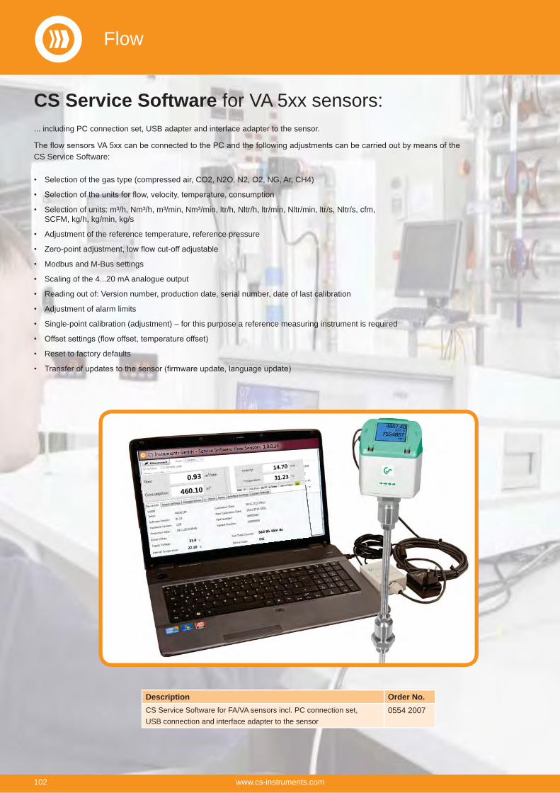
CS Service Software for VA 5xx sensors:... including PC connection set, USB adapter and interface adapter to the sensor.
CS Service Software:
Selection of the gas type (compressed air, CO2, N2O, N2, O2, NG, Ar, CH4)
Selection of units: m³/h, Nm³/h, m³/min, Nm³/min, ltr/h, Nltr/h, ltr/min, Nltr/min, ltr/s, Nltr/s, cfm, SCFM, kg/h, kg/min, kg/s
Adjustment of the reference temperature, reference pressure
Modbus and M-Bus settings
Scaling of the 4...20 mA analogue output
Reading out of: Version number, production date, serial number, date of last calibration
Adjustment of alarm limits
Single-point calibration (adjustment) – for this purpose a reference measuring instrument is required
Reset to factory defaults
Description Order No.CS Service Software for FA/VA sensors incl. PC connection set, USB connection and interface adapter to the sensor
0554 2007
Flow
102 www.cs-instruments.com
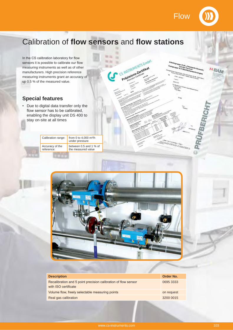
Calibration of flow sensors and flow stations
measuring instruments as well as of other manufacturers. High precision reference measuring instruments grant an accuracy of up 0.5 % of the measured value.
Special featuresDue to digital data transfer only the
enabling the display unit DS 400 to stay on-site at all times
Calibration range: from 0 to 4,000 m³/hunder pressure
Accuracy of the reference:
between 0.5 and 1 % of the measured value
Description Order No.0695 3333
on request
Real gas calibration 3200 0015
Flow
103www.cs-instruments.com
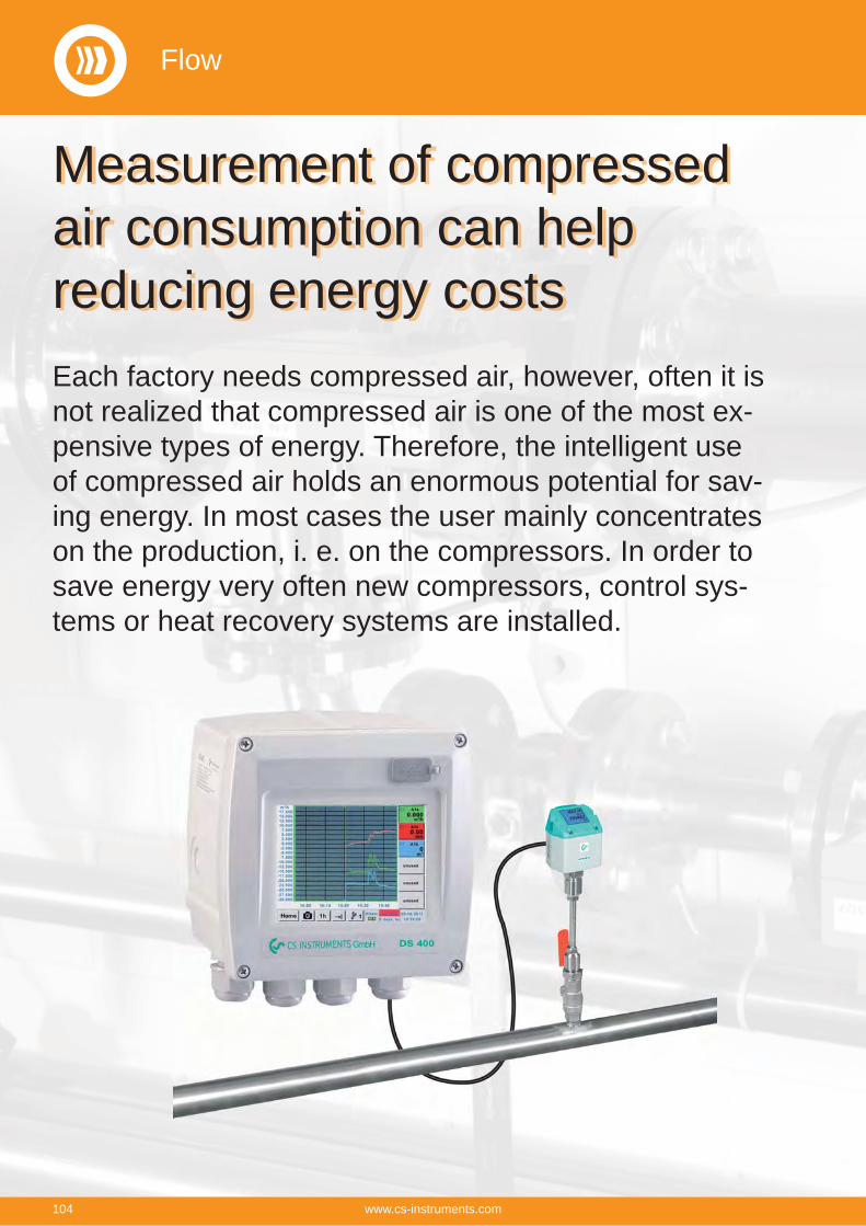
Each factory needs compressed air, however, often it is not realized that compressed air is one of the most ex-pensive types of energy. Therefore, the intelligent use of compressed air holds an enormous potential for sav-ing energy. In most cases the user mainly concentrates on the production, i. e. on the compressors. In order to save energy very often new compressors, control sys-tems or heat recovery systems are installed.
Measurement of compressed air consumption can help reducing energy costs
Flow
104 www.cs-instruments.com
If we talk about operational costs of compressed air plants we are actu-ally talking about the energy costs as they make up about 70 to 80 % of the total costs of a compressed air plant.
Depending on the size of the plant this means considerable operat-ing costs. Even in smaller plants this may quickly add up to 10,000 to 20,000 € per year. This is an amount which can be consider-ably reduced – even in case of well operated and maintained plants.
In case of a three shift operation with 200 kW compressor perfor-mance a bad compressed air distri-bution can create redundant energy costs of more than 50,000 € per year.
This mainly concerns to the elimi-nation of leakages and the correct diameters of the compressed air lines for minimization of the pres-sure losses.
Energy resources like electricity, water or gas are usually monitored and therefore the costs are trans-parent.
Contrary to compressed air, a water leak is usually found quickly due to the visibility of the leak and therefore they are eliminated imme-diately. Compressed air leaks are often not noticed and can ”silently” cause a lot of unnecessary costs, even during production downtime or over the weekend.
Also during that time compressors are running continuously in order to establish a constant pressure within the system. In case of compressed air systems which have grown dur-ing the years the leakage rate can be between 25 and 35 per cent.
They are the busiest consumers of compressed air, working all around 365 days a year.
Not included are the hidden costs of producing clean and dry com-pressed air. Refrigeration and des-
iccant driers are producing dry air with high running costs involved. Air that is then later lost through leaks within the system.
At constantly rising energy costs these potential energy savings have to be implemented in order to stay competitive within the mar-ket. Only if the consumption of single machines or plants becomes known and transparent for all it is possible to make use of possible savings.
However, often any knowledge about the leak ratio is missing. In the following we show you how you can easily determine the leakage amounts in your company.
Formerly the simple but inac-curate container method was applied very often
A simplified determination of the leakages is possible by means of the emptying of the tank.
For carrying out this measure-ment you just need a clock and a manometer.
Furthermore you should know the storage volume of the tank as well as of the compressed air system.
For measurement first the tank and the compressed air system are set to the upper cut-out pressure value. All compressed air consumers have to be switched off.
Then the compressor is switched off and there will be no compressed air feeding into the system.
Now the time T is measured which passes by until there is a pressure drop of 1 to 2 bar due to the leak-ages.
The pressure drop between which the measurement is taking place can be selected freely.
However, in practice the described method is very time-consuming, not adequate and inaccurate due to the following reasons:
Storage volume, distribution pipe-lines cannot be determined exactly.
The accuracy of the differential pressure measurement and time measurement has to be observed
During pressure drop the com-pressed air volume cools down and therefore it changes the volume flow reference value
An online measurement with con-sumption record is not possible
This method belongs to the so-called indirect measurements, like also the method of the load and unload measurement during which the current intake is measured by means of clamp-on ammeters and calculated back to the volume flow over the technical data of the com-pressor.
These indirect methods are anti-quated and not suitable to detect leakages in the lower measuring range.
Determination of compressed air leakages with modern flow meters
A modern compressed air con-sumption measurement resp. leak-age measurement should be able to measure the real compressed air flow and also the smallest leakages quickly and reliably and record them.
Flow
105www.cs-instruments.com
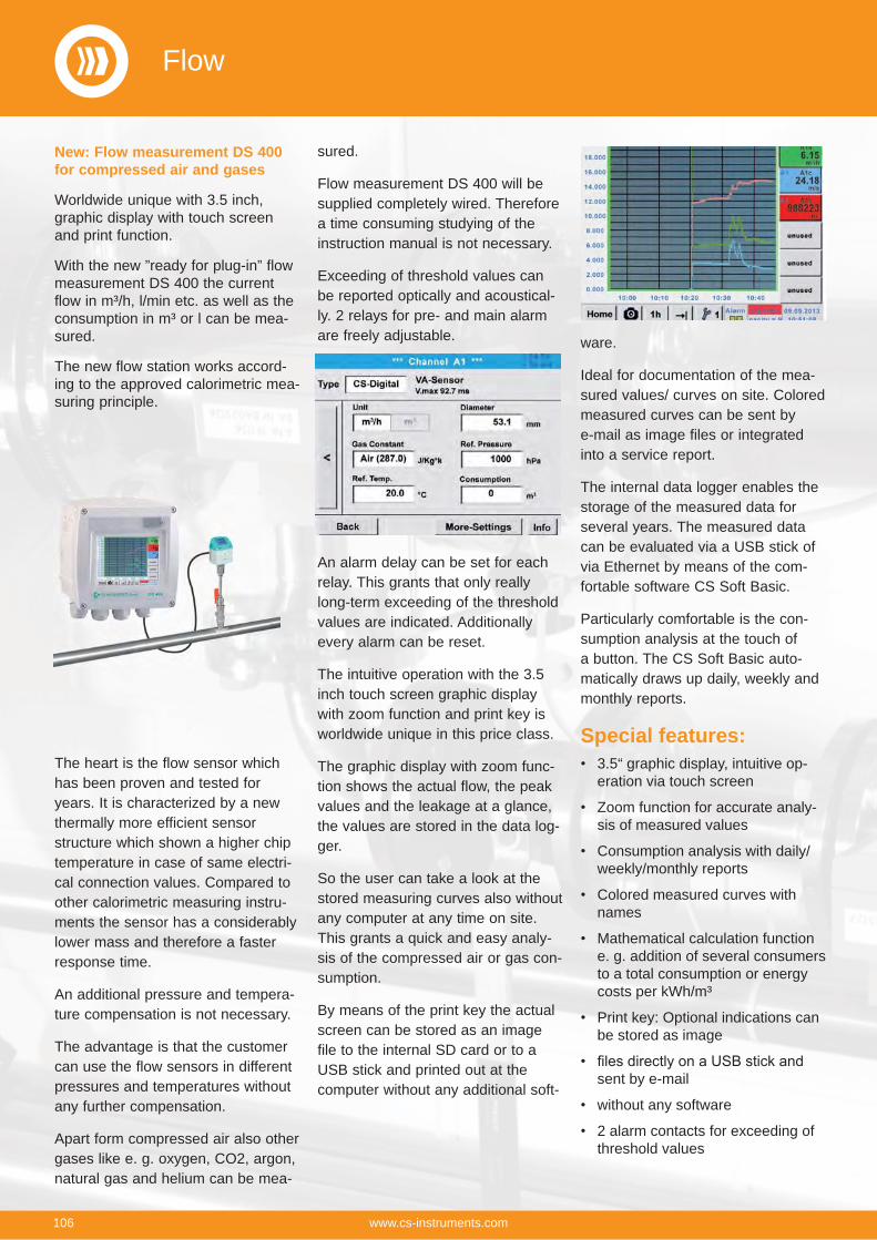
The heart is the flow sensor which has been proven and tested for years. It is characterized by a new thermally more efficient sensor structure which shown a higher chip temperature in case of same electri-cal connection values. Compared to other calorimetric measuring instru-ments the sensor has a considerably lower mass and therefore a faster response time.
An additional pressure and tempera-ture compensation is not necessary.
The advantage is that the customer can use the flow sensors in different pressures and temperatures without any further compensation.
Apart form compressed air also other gases like e. g. oxygen, CO2, argon, natural gas and helium can be mea-
sured.
Flow measurement DS 400 will be supplied completely wired. Therefore a time consuming studying of the instruction manual is not necessary.
Exceeding of threshold values can be reported optically and acoustical-ly. 2 relays for pre- and main alarm are freely adjustable.
An alarm delay can be set for each relay. This grants that only really long-term exceeding of the threshold values are indicated. Additionally every alarm can be reset.
The intuitive operation with the 3.5 inch touch screen graphic display with zoom function and print key is worldwide unique in this price class.
The graphic display with zoom func-tion shows the actual flow, the peak values and the leakage at a glance, the values are stored in the data log-ger.
So the user can take a look at the stored measuring curves also without any computer at any time on site. This grants a quick and easy analy-sis of the compressed air or gas con-sumption.
By means of the print key the actual screen can be stored as an image file to the internal SD card or to a USB stick and printed out at the computer without any additional soft-
New: Flow measurement DS 400 for compressed air and gases
Worldwide unique with 3.5 inch,graphic display with touch screen and print function.
With the new ”ready for plug-in” flow measurement DS 400 the current flow in m³/h, l/min etc. as well as the consumption in m³ or l can be mea-sured.
The new flow station works accord-ing to the approved calorimetric mea-suring principle.
ware.
Ideal for documentation of the mea-sured values/ curves on site. Colored measured curves can be sent by e-mail as image files or integrated into a service report.
The internal data logger enables the storage of the measured data for several years. The measured data can be evaluated via a USB stick of via Ethernet by means of the com-fortable software CS Soft Basic.
Particularly comfortable is the con-sumption analysis at the touch of a button. The CS Soft Basic auto-matically draws up daily, weekly and monthly reports.
Special features:3.5“ graphic display, intuitive op-eration via touch screen
Zoom function for accurate analy-sis of measured values
Consumption analysis with daily/weekly/monthly reports
Colored measured curves with names
Mathematical calculation function e. g. addition of several consumers to a total consumption or energy costs per kWh/m³
Print key: Optional indications can be stored as image
sent by e-mail
without any software
2 alarm contacts for exceeding of threshold values
Flow
106 www.cs-instruments.com
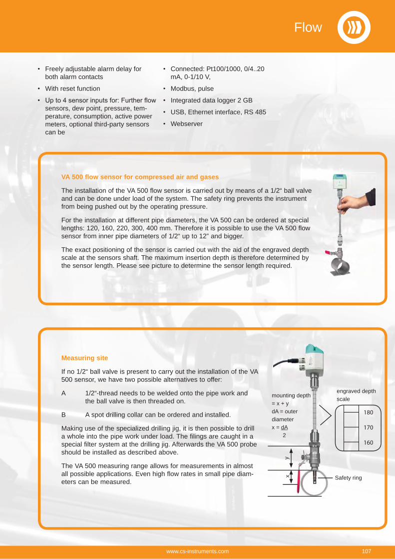
VA 500 flow sensor for compressed air and gases
The installation of the VA 500 flow sensor is carried out by means of a 1/2“ ball valve and can be done under load of the system. The safety ring prevents the instrument from being pushed out by the operating pressure.
For the installation at different pipe diameters, the VA 500 can be ordered at special lengths: 120, 160, 220, 300, 400 mm. Therefore it is possible to use the VA 500 flow sensor from inner pipe diameters of 1/2“ up to 12” and bigger.
The exact positioning of the sensor is carried out with the aid of the engraved depth scale at the sensors shaft. The maximum insertion depth is therefore determined by the sensor length. Please see picture to determine the sensor length required.
Measuring site
If no 1/2“ ball valve is present to carry out the installation of the VA 500 sensor, we have two possible alternatives to offer:
A 1/2“-thread needs to be welded onto the pipe work and the ball valve is then threaded on.
B A spot drilling collar can be ordered and installed.
Making use of the specialized drilling jig, it is then possible to drill a whole into the pipe work under load. The filings are caught in a special filter system at the drilling jig. Afterwards the VA 500 probe should be installed as described above.
The VA 500 measuring range allows for measurements in almost all possible applications. Even high flow rates in small pipe diam-eters can be measured.
Freely adjustable alarm delay for both alarm contacts
With reset function
sensors, dew point, pressure, tem-perature, consumption, active power meters, optional third-party sensors can be
Connected: Pt100/1000, 0/4..20 mA, 0-1/10 V,
Modbus, pulse
Integrated data logger 2 GB
USB, Ethernet interface, RS 485
Webserver
mounting depth = x + ydA = outer diameterx = dA 2
yx
180
170
160
engraved depth scale
Safety ring
Flow
107www.cs-instruments.com
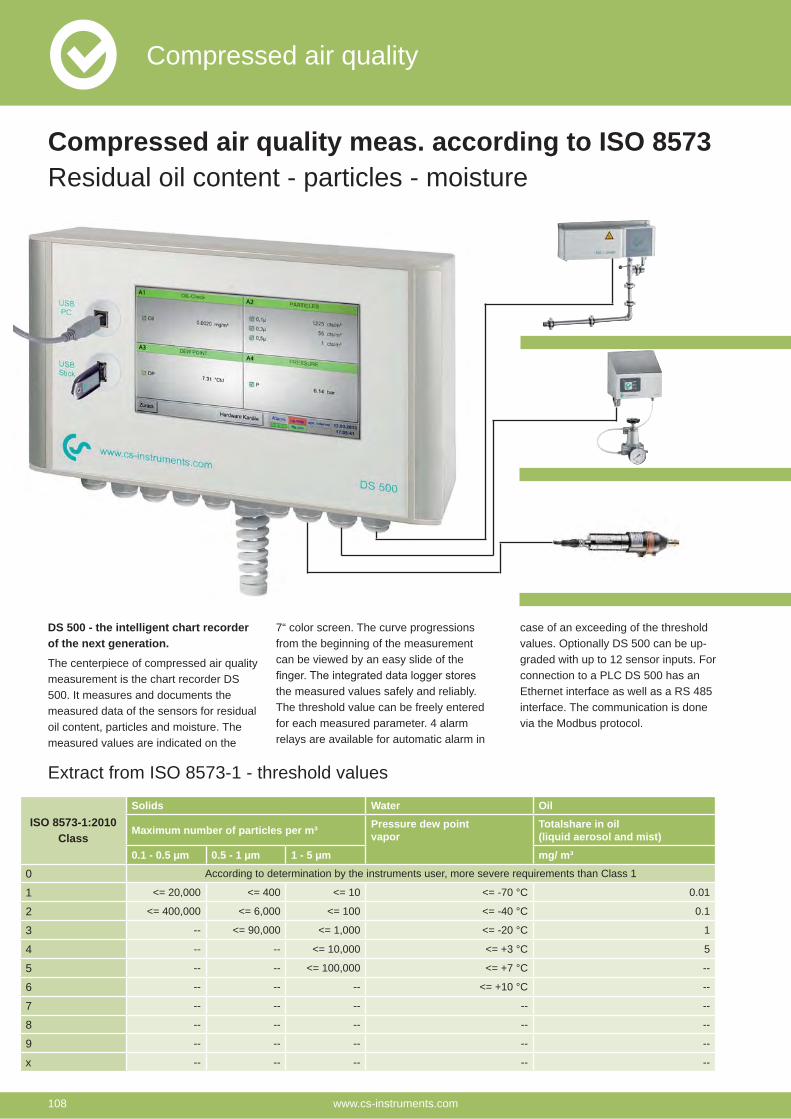
DS 500 - the intelligent chart recorder of the next generation.
The centerpiece of compressed air quality measurement is the chart recorder DS 500. It measures and documents the measured data of the sensors for residual oil content, particles and moisture. The measured values are indicated on the
7“ color screen. The curve progressions from the beginning of the measurement can be viewed by an easy slide of the
the measured values safely and reliably. The threshold value can be freely entered for each measured parameter. 4 alarm relays are available for automatic alarm in
case of an exceeding of the threshold values. Optionally DS 500 can be up-graded with up to 12 sensor inputs. For connection to a PLC DS 500 has an Ethernet interface as well as a RS 485 interface. The communication is done via the Modbus protocol.
Extract from ISO 8573-1 - threshold values
ISO 8573-1:2010Class
Solids Water Oil
Maximum number of particles per m³ Pressure dew pointvapor
Totalshare in oil (liquid aerosol and mist)
0.1 - 0.5 μm 0.5 - 1 μm 1 - 5 μm mg/ m³
0 According to determination by the instruments user, more severe requirements than Class 1
1 <= 20,000 <= 400 <= 10 <= -70 °C 0.01
2 <= 400,000 <= 6,000 <= 100 <= -40 °C 0.1
3 -- <= 90,000 <= 1,000 <= -20 °C 1
4 -- -- <= 10,000 <= +3 °C 5
5 -- -- <= 100,000 <= +7 °C --
6 -- -- -- <= +10 °C --
7 -- -- -- -- --
8 -- -- -- -- --
9 -- -- -- -- --
x -- -- -- -- --
Compressed air quality meas. according to ISO 8573 Residual oil content - particles - moisture
Compressed air quality
www.cs-instruments.com108
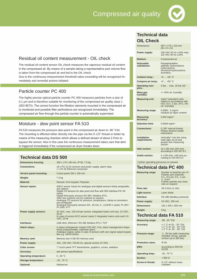
Residual oil content measurement - OIL checkThe residual oil content sensor OIL check measures the vaporous residual oil content
is taken from the compressed air and led to the OIL check.Due to the continuous measurement threshold value exceeding will be recognized im-mediately and remedial actions initiated.
Particle counter PC 400The highly precise optical particle counter PC 400 measures particles from a size of 0.1 μm and is therefore suitable for monitoring of the compressed air quality class 1
Moisture - dew point sensor FA 510FA 510 measures the pressure dew point in the compressed air down to -80 °Ctd. The mounting is effected either directly into the pipe via the G 1/2“ thread or better by
bypass the sensor. Also in this case the continuous measurement takes care that alert is triggered immediately if the compressed air dryer breaks down.
Technical data OIL CheckDimensions: 487 x 170 x 120 mm
(W x H x D)
Power supply: 230 VAC 50 Hz ±10% resp. 115 VAC 60 Hz ±10%
Medium: Compressed air
Noticeablesubstances aliphatic hydrocarbons
hydrocarbonsfunctional hydrocarbonsaromatics
Ambient temp.: +5 ... +45 °C
Compres.air temp.: +5 ... +55 °C
Operating over-pres.:
3 bar ... max. 16 bar (ü)*
Meas.gas humidity:
<= 40% rel. humidity
Measuring unit: mg/m³ (standard cubic meters in accordance with ISO 1217; 1 bar, 20°C, 0% rel. humidity)
Measuring range: 0,0006 - 5 mg/m³residual oil vapor content
Measuring accuracy:
0.003 mg/m³
Detection limit: 0.0006 mg/m³
Connections: G 3/8“ internal thread. Please observe install. instructions
Installation requirements:
Vertically** into the rising main pipe via oil and grease free measuring section
Inlet section: 10 x DN (min.200 mm)according to ISO 8573-2
Outlet section: 3 x DN (min. 100 mm) ac-cording to ISO 8573-2
* further operating pressures on request** horizontal mounting on requestTechnical data PC 400Measuring range: Number of particles per m³
Particle size channels:0.1...0.5 μm, 0.5...1 μm,1...5 μmFurther particle size chan-nels on request
Flow rate: 28.3 l/min (1 cfm)
Light source: Laser diode
Interface: RS 485 (Modbus protocol)
Power supply: 24 VDC, 300 mA
Dimensions: 150 x 200 x 300 mm
Weight: 8 kg
Technical data FA 510Measuring range: -80...20 °Ctd
Accuracy: ± 1 °C at 20...-20 °Ctd± 2 °C at -20...-50 °Ctd± 3 °C at -50...-80 °Ctd
Pressure range: -1...50 bar (with measuring chamber 16 bar, special version up to 350 bar)
Protection class: IP 65
EMV: according to DIN EN 61326
Operating temp.: -20...70 °C
Burden:
Screw-in thread: G 1/2“ without meas.chamber
Technical data DS 500Dimensions housing: 280 x 170 x 90 mm, IP 65, 7.3 kg
Connections: 18 x PG 12 for sensors and power supply, alarm relay1 x RJ 45 Ethernet connection
Version panel mounting: Cutout panel 250 x 156 mm
Weight: 7.3 kg
Material: Diecast, front keypad: Polyester
Sensor inputs: 4/8/12 sensor inputs for analogue and digital sensors freely assignable, see options.
series.Digital third-party sensors RS 485 / Modbus RTU,other bus systems can be realized on request.Analogue CS sensors for pressure, temperature, clamp-on ammeters
Analogue third-party sensors 0/4...20 mA, 0...1/10/30 V, pulse, Pt 100 / Pt 1000, KTY
Power supply sensors: 24 VDC, max. 130 mA per sensor, integrated mains unit max. 24 VDC, 25 WIn case of version 8/12 sensor inputs 2 integrated mains units each 24 VDC, 25 W
Interfaces: USB stick, Ethernet / RS 485 Modbus RTU / TCP
Alarm relays: 4 relays (changeover contact 230 VAC, 6 A), alarm management relays freely programmable, collective alarm.Analogue output, pulse in case of sensors with own signal output looped, like e.g. VA/FA Series
Memory card: Memory size 4 GB SD memory card
Power supply: 100...240 VAC / 50-60 Hz, special version 24 VDC
Color screen: 7“ touch panel TFT transmissive, graphics, curves, statistics
Accuracy:
Operating temperature: 0...50 °C
Storage temperature: -20...70 °C
Optional: Webserver
Compressed air quality
www.cs-instruments.com 109
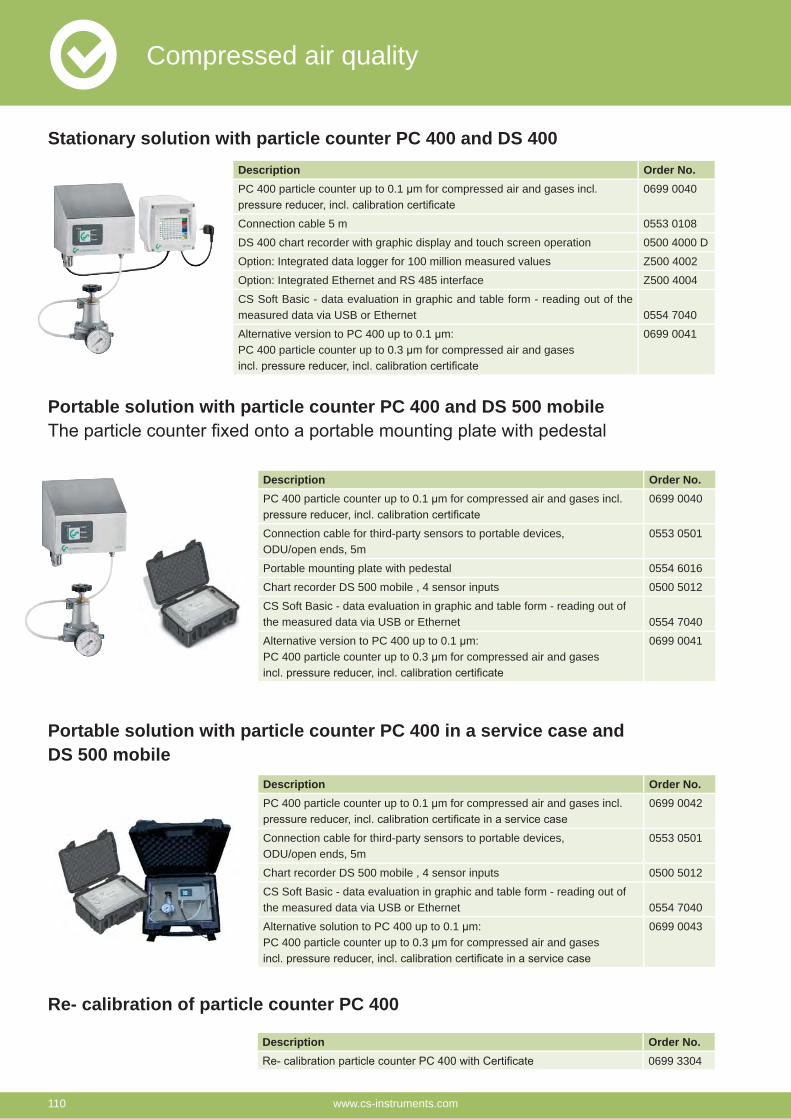
Description Order No.PC 400 particle counter up to 0.1 μm for compressed air and gases incl. 0699 0040
Connection cable 5 m 0553 0108
DS 400 chart recorder with graphic display and touch screen operation 0500 4000 D
Option: Integrated data logger for 100 million measured values Z500 4002
Option: Integrated Ethernet and RS 485 interface Z500 4004
CS Soft Basic - data evaluation in graphic and table form - reading out of the measured data via USB or Ethernet 0554 7040
Alternative version to PC 400 up to 0.1 μm:PC 400 particle counter up to 0.3 μm for compressed air and gases
0699 0041
Description Order No.PC 400 particle counter up to 0.1 μm for compressed air and gases incl. 0699 0040
Connection cable for third-party sensors to portable devices, ODU/open ends, 5m
0553 0501
Portable mounting plate with pedestal 0554 6016
Chart recorder DS 500 mobile , 4 sensor inputs 0500 5012
CS Soft Basic - data evaluation in graphic and table form - reading out of the measured data via USB or Ethernet 0554 7040
Alternative version to PC 400 up to 0.1 μm:PC 400 particle counter up to 0.3 μm for compressed air and gases
0699 0041
Description Order No.PC 400 particle counter up to 0.1 μm for compressed air and gases incl. 0699 0042
Connection cable for third-party sensors to portable devices, ODU/open ends, 5m
0553 0501
Chart recorder DS 500 mobile , 4 sensor inputs 0500 5012
CS Soft Basic - data evaluation in graphic and table form - reading out of the measured data via USB or Ethernet 0554 7040
Alternative solution to PC 400 up to 0.1 μm:PC 400 particle counter up to 0.3 μm for compressed air and gases
0699 0043
Stationary solution with particle counter PC 400 and DS 400
Portable solution with particle counter PC 400 and DS 500 mobile
Portable solution with particle counter PC 400 in a service case and DS 500 mobile
Re- calibration of particle counter PC 400
Description Order No.0699 3304
Compressed air quality
www.cs-instruments.com110
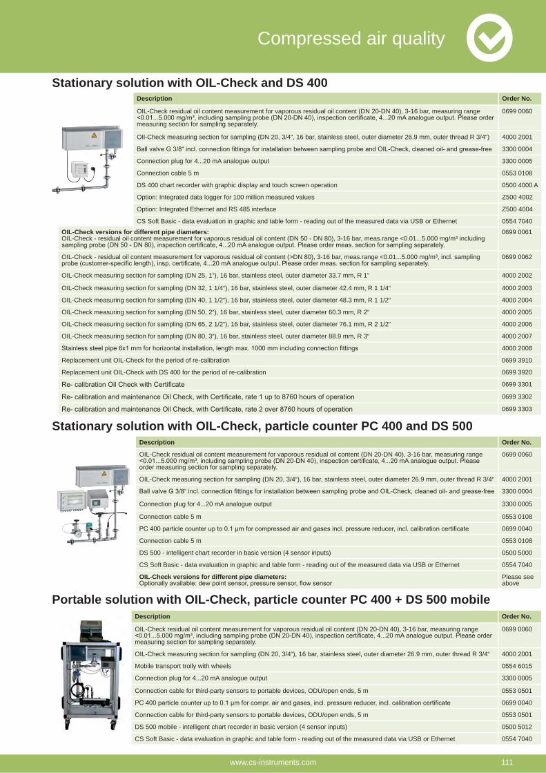
Stationary solution with OIL-Check and DS 400
Description Order No.
OIL-Check residual oil content measurement for vaporous residual oil content (DN 20-DN 40), 3-16 bar, measuring range
order measuring section for sampling separately.
0699 0060
OIL-Check measuring section for sampling (DN 20, 3/4“), 16 bar, stainless steel, outer diameter 26.9 mm, outer thread R 3/4“ 4000 2001
3300 0004
Connection plug for 4...20 mA analogue output 3300 0005
Connection cable 5 m 0553 0108
0699 0040
Connection cable 5 m 0553 0108
DS 500 - intelligent chart recorder in basic version (4 sensor inputs) 0500 5000
CS Soft Basic - data evaluation in graphic and table form - reading out of the measured data via USB or Ethernet 0554 7040
OIL-Check versions for different pipe diameters: Please see above
Portable solution with OIL-Check, particle counter PC 400 + DS 500 mobile
OIL-Check versions for different pipe diameters:OIL-Check - residual oil content measurement for vaporous residual oil content (DN 50 - DN 80), 3-16 bar, meas.range <0.01...5.000 mg/m³ including
0699 0061
OIL-Check - residual oil content measurement for vaporous residual oil content (>DN 80), 3-16 bar, meas.range <0.01...5.000 mg/m³, incl. sampling 0699 0062
OIL-Check measuring section for sampling (DN 25, 1“), 16 bar, stainless steel, outer diameter 33.7 mm, R 1“ 4000 2002
OIL-Check measuring section for sampling (DN 32, 1 1/4“), 16 bar, stainless steel, outer diameter 42.4 mm, R 1 1/4“ 4000 2003
OIL-Check measuring section for sampling (DN 40, 1 1/2“), 16 bar, stainless steel, outer diameter 48.3 mm, R 1 1/2“ 4000 2004
OIL-Check measuring section for sampling (DN 50, 2“), 16 bar, stainless steel, outer diameter 60.3 mm, R 2“ 4000 2005
OIL-Check measuring section for sampling (DN 65, 2 1/2“), 16 bar, stainless steel, outer diameter 76.1 mm, R 2 1/2“ 4000 2006
OIL-Check measuring section for sampling (DN 80, 3“), 16 bar, stainless steel, outer diameter 88.9 mm, R 3“ 4000 2007
4000 2008
Replacement unit OIL-Check for the period of re-calibration 0699 3910
Replacement unit OIL-Check with DS 400 for the period of re-calibration 0699 3920
0699 3301
0699 3302
0699 3303
Stationary solution with OIL-Check, particle counter PC 400 and DS 500
Description Order No.
OIL-Check residual oil content measurement for vaporous residual oil content (DN 20-DN 40), 3-16 bar, measuring range
measuring section for sampling separately.
0699 0060
OIL-Check measuring section for sampling (DN 20, 3/4“), 16 bar, stainless steel, outer diameter 26.9 mm, outer thread R 3/4“ 4000 2001
Mobile transport trolly with wheels 0554 6015
Connection plug for 4...20 mA analogue output 3300 0005
Connection cable for third-party sensors to portable devices, ODU/open ends, 5 m 0553 0501
0699 0040
Connection cable for third-party sensors to portable devices, ODU/open ends, 5 m 0553 0501
DS 500 mobile - intelligent chart recorder in basic version (4 sensor inputs) 0500 5012
CS Soft Basic - data evaluation in graphic and table form - reading out of the measured data via USB or Ethernet 0554 7040
Description Order No.
OIL-Check residual oil content measurement for vaporous residual oil content (DN 20-DN 40), 3-16 bar, measuring range
measuring section for sampling separately.
0699 0060
OIl-Check measuring section for sampling (DN 20, 3/4“, 16 bar, stainless steel, outer diameter 26.9 mm, outer thread R 3/4“) 4000 2001
3300 0004
Connection plug for 4...20 mA analogue output 3300 0005
Connection cable 5 m 0553 0108
DS 400 chart recorder with graphic display and touch screen operation 0500 4000 A
Option: Integrated data logger for 100 million measured values Z500 4002
Option: Integrated Ethernet and RS 485 interface Z500 4004
CS Soft Basic - data evaluation in graphic and table form - reading out of the measured data via USB or Ethernet 0554 7040
Compressed air quality
www.cs-instruments.com 111
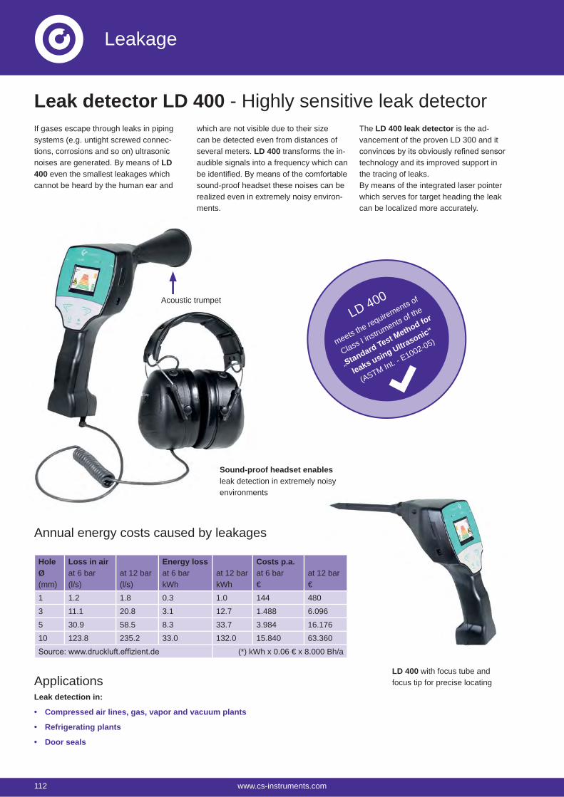
Leakage
If gases escape through leaks in piping systems (e.g. untight screwed connec-tions, corrosions and so on) ultrasonic noises are generated. By means of LD 400 even the smallest leakages which cannot be heard by the human ear and
The LD 400 leak detector is the ad-vancement of the proven LD 300 and it
technology and its improved support in the tracing of leaks.By means of the integrated laser pointer which serves for target heading the leak can be localized more accurately.
which are not visible due to their size can be detected even from distances of several meters. LD 400 transforms the in-audible signals into a frequency which can
sound-proof headset these noises can be realized even in extremely noisy environ-ments.
Sound-proof headset enablesleak detection in extremely noisy environments
Acoustic trumpet
LD 400 with focus tube and focus tip for precise locating
Annual energy costs caused by leakages
ApplicationsLeak detection in:
Compressed air lines, gas, vapor and vacuum plants
Refrigerating plants
Door seals
Leak detector LD 400 - Highly sensitive leak detector
LD 400
meets the requirements of
Class I instruments of the
„Standard Test Method for
leaks using Ultrasonic“
(ASTM Int. - E1002-05)
HoleØ(mm)
Loss in airat 6 bar(l/s)
at 12 bar(l/s)
Energy lossat 6 barkWh
at 12 barkWh
Costs p.a.at 6 bar€
at 12 bar€
1 1.2 1.8 0.3 1.0 144 480
3 11.1 20.8 3.1 12.7 1.488 6.096
5 30.9 58.5 8.3 33.7 3.984 16.176
10 123.8 235.2 33.0 132.0 15.840 63.360
(*) kWh x 0.06 € x 8.000 Bh/a
112 www.cs-instruments.com
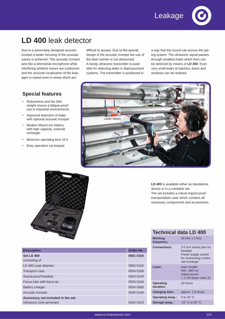
Leakage
Description Order No.Set LD 400consisting of:
0601 0104
LD 400 Leak detector 0560 0104
Transport case 0554 0106
Sound-proof headset 0554 0104
Focus tube with focus tip 0530 0104
Battery charger 0554 0009
Acoustic trumpet 0530 0109
Accessory, not included in the set:Ultrasonic tone generator 0554 0103
Due to a particularly designed acoustic trumpet a better focusing of the acoustic waves is achieved. This acoustic trumpet acts like a directional microphone while interfering ambient noises are cushioned and the accurate localization of the leak-ages is eased even in areas which are
a way that the sound can access the pip-ing system. The ultrasonic signal passes through smallest holes which then can be detected by means of LD 400. Even very small leaks at hatches, doors and windows can be realized.
design of the acoustic trumpet the use of the laser pointer is not obstructed. A handy ultrasonic transmitter is avail-able for detecting leaks in depressurized systems. The transmitter is positioned in
Laser beam
LD 400 is available either as standalone device or in a complete set.The set includes a robust impact-proof transportation case which contains all necessary components and accessories.
LD 400 leak detector
Special featuresRobustness and the little weight ensure a fatigue-proof use in industrial environments
Improved detection of leaks with optional acoustic trumpet
Modern lithium-ion battery with high capacity, external recharger
Minimum operating time 10 h
Easy operation via keypad
Technical data LD 400Workingfrequency:
40 kHz ± 2 kHz
Connections: 3.5 mm stereo jack for headsetPower supply socket for connecting a exter-nal recharger
Laser: wave length:645...660 nmoutput power:< 1 nW (laser class 2)
Operatingduration:
10 hours
Charging time: approx. 1.5 hours
Operating temp.: 0 to 40 °C
Storage temp.: -10 °C to 50 °C
www.cs-instruments.com 113
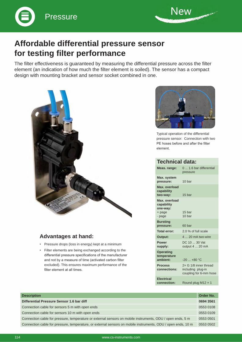
Pressure
Description Order No.Differential Pressure Sensor 1.6 bar diff 0694 3561Connection cable for sensors 5 m with open ends 0553 0108
Connection cable for sensors 10 m with open ends 0553 0109
Connection cable for pressure, temperature or external sensors on mobile instruments, ODU / open ends, 5 m 0553 0501
Connection cable for pressure, temperature, or external sensors on mobile instruments, ODU / open ends, 10 m 0553 0502
Affordable differential pressure sensor for testing filter performanceThe filter effectiveness is guaranteed by measuring the differential pressure across the filter element (an indication of how much the filter element is soiled). The sensor has a compact design with mounting bracket and sensor socket combined in one.
Technical data:Meas. range: 0 ... 1.6 bar differential
pressure
Max. system pressure: 10 bar
Max. overload capability two-way: 15 bar
Max. overload capability one-way:+ page- page
15 bar10 bar
Bursting pressure: 60 bar
Total error: 2.0 % of full scale
Output: 4 ... 20 mA two-wire
Power supply:
DC 10 ... 30 Vat output 4 ... 20 mA
Operating temperature ambient: -20 ... +80 °C
Process connections:
2× G 1/8 inner thread including plug-in coupling for 6-mm hose
Electricalconnection: Round plug M12 × 1
Typical operation of the differential pressure sensor: Connection with two
element.
Advantages at hand:Pressure drops (loss in energy) kept at a minimum
Filter elements are being exchanged according to the
excluded). This ensures maximum performance of the
114 www.cs-instruments.com
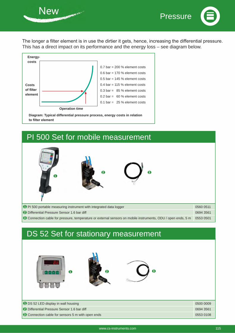
Pressure
12 3
PI 500 portable measuring instrument with integrated data logger 0560 0511
Differential Pressure Sensor 1.6 bar diff 0694 3561
Connection cable for pressure, temperature or external sensors on mobile instruments, ODU / open ends, 5 m 0553 0501
PI 500 Set for mobile measurement
3
1
2
1 2 3
DS 52 LED display in wall housing 0500 0009
Differential Pressure Sensor 1.6 bar diff 0694 3561
Connection cable for sensors 5 m with open ends 0553 0108
DS 52 Set for stationary measurement
3
1
2
This has a direct impact on its performance and the energy loss – see diagram below.
0.7 bar = 200 % element costs
0.6 bar = 170 % element costs
0.5 bar = 145 % element costs
0.4 bar = 115 % element costs
0.3 bar = 85 % element costs
0.2 bar = 60 % element costs
0.1 bar = 25 % element costs
Operation time
Costs
element
Energy-costs
Diagram: Typical differential pressure process, energy costs in relation
www.cs-instruments.com 115
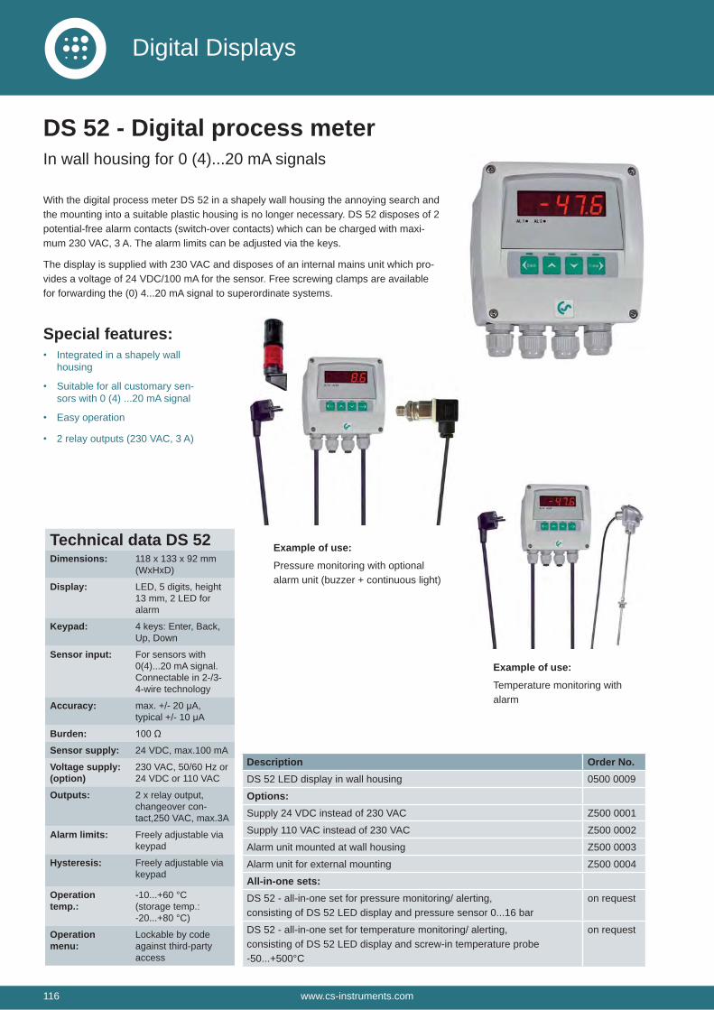
With the digital process meter DS 52 in a shapely wall housing the annoying search and the mounting into a suitable plastic housing is no longer necessary. DS 52 disposes of 2 potential-free alarm contacts (switch-over contacts) which can be charged with maxi-mum 230 VAC, 3 A. The alarm limits can be adjusted via the keys.
The display is supplied with 230 VAC and disposes of an internal mains unit which pro-vides a voltage of 24 VDC/100 mA for the sensor. Free screwing clamps are available for forwarding the (0) 4...20 mA signal to superordinate systems.
Special features:Integrated in a shapely wall housing
Suitable for all customary sen-sors with 0 (4) ...20 mA signal
Easy operation
2 relay outputs (230 VAC, 3 A)
Example of use:
Pressure monitoring with optional alarm unit (buzzer + continuous light)
Example of use:
Temperature monitoring with alarm
Description Order No.DS 52 LED display in wall housing 0500 0009
Options:Supply 24 VDC instead of 230 VAC Z500 0001
Supply 110 VAC instead of 230 VAC Z500 0002
Alarm unit mounted at wall housing Z500 0003
Alarm unit for external mounting Z500 0004
All-in-one sets:DS 52 - all-in-one set for pressure monitoring/ alerting, consisting of DS 52 LED display and pressure sensor 0...16 bar
on request
DS 52 - all-in-one set for temperature monitoring/ alerting,consisting of DS 52 LED display and screw-in temperature probe -50...+500°C
on request
DS 52 - Digital process meterIn wall housing for 0 (4)...20 mA signals
Technical data DS 52Dimensions: 118 x 133 x 92 mm
(WxHxD)
Display: LED, 5 digits, height 13 mm, 2 LED for alarm
Keypad: 4 keys: Enter, Back, Up, Down
Sensor input: For sensors with 0(4)...20 mA signal. Connectable in 2-/3-4-wire technology
Accuracy: max. +/- 20 μA,typical +/- 10 μA
Burden:Sensor supply: 24 VDC, max.100 mA
Voltage supply: (option)
230 VAC, 50/60 Hz or 24 VDC or 110 VAC
Outputs: 2 x relay output, changeover con-tact,250 VAC, max.3A
Alarm limits: Freely adjustable via keypad
Hysteresis: Freely adjustable via keypad
Operation temp.:
-10...+60 °C(storage temp.: -20...+80 °C)
Operation menu:
Lockable by code against third-party access
116 www.cs-instruments.com
Digital Displays
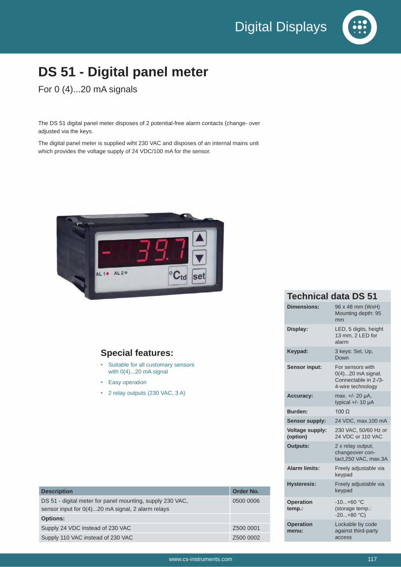
The DS 51 digital panel meter disposes of 2 potential-free alarm contacts (change- over adjusted via the keys.
The digital panel meter is supplied wiht 230 VAC and disposes of an internal mains unit which provides the voltage supply of 24 VDC/100 mA for the sensor.
Special features:Suitable for all customary sensors with 0(4)...20 mA signal
Easy operation
2 relay outputs (230 VAC, 3 A)
DS 51 - Digital panel meterFor 0 (4)...20 mA signals
Technical data DS 51Dimensions: 96 x 48 mm (WxH)
Mounting depth: 95 mm
Display: LED, 5 digits, height 13 mm, 2 LED for alarm
Keypad: 3 keys: Set, Up, Down
Sensor input: For sensors with 0(4)...20 mA signal. Connectable in 2-/3-4-wire technology
Accuracy: max. +/- 20 μA,typical +/- 10 μA
Burden:Sensor supply: 24 VDC, max.100 mA
Voltage supply: (option)
230 VAC, 50/60 Hz or 24 VDC or 110 VAC
Outputs: 2 x relay output, changeover con-tact,250 VAC, max.3A
Alarm limits: Freely adjustable via keypad
Hysteresis: Freely adjustable via keypad
Operation temp.:
-10...+60 °C(storage temp.: -20...+80 °C)
Operation menu:
Lockable by code against third-party access
Description Order No.DS 51 - digital meter for panel mounting, supply 230 VAC,sensor input for 0(4)...20 mA signal, 2 alarm relays
0500 0006
Options:Supply 24 VDC instead of 230 VAC Z500 0001
Supply 110 VAC instead of 230 VAC Z500 0002
www.cs-instruments.com 117
Digital Displays

Notes:
118 www.cs-instruments.com

Notes:
www.cs-instruments.com 119

SALES OFFICE NORTHCS INSTRUMENTS GMBH & CO. KGAm Oxer 28cD-24955 HarrisleeGERMANYP: +49 (0) 461 700 20 25F: +49 (0) 461 700 20 [email protected]
SALES OFFICE SOUTHCS INSTRUMENTS GMBH & CO. KGZindelsteiner Straße 15D-78052 VS-TannheimGERMANYP: +49 (0) 7705 978 99-0F: +49 (0) 7705 978 [email protected]
V02
www.cs-instruments.com