Embed Size (px)
Citation preview

4-1
Catalogue HY11-3500/UK
Parker Hannifin GmbH & Co. KGHydraulic Controls DivisionKaarst, Germany
content04.INDD CM
4
ContentsChapter 4:Pressure Valves
More check valves are presented in the following chapters:Chapter 7: Sandwich ValvesChapter 8: Slip-In Cartridge ValvesChapter 9: SAE Flange ValvesChapter 10: Valves for Pipe Mounting
SeriesDescription Size Mounting Operation Page
Parker Denison
Parker StandardDIN / ISO
06 1006 10 25 32 S
ubpl
ate
Scr
ew-in
Dire
ct
Pilo
t
Pressure relief valves,manual operation
VSVBVBYEVSAR/RSDSDU
––––
R4V/R6V–
For high secondary pressureFor high secondary pressure
With German certificate (TÜV)
• •
•••
••
••
••
••
•••
••
•
••
••
••
4-34-7
4-134-194-234-35
Pressure relief valves,proportional operation
RE06M*WRE06M*TRE*WRE*TVBY*K
4VP01–
R4V/R6VR4V/R6V
– For high secondary pressure
••
•
•••
••
••
•••••
••
•••
4-394-434-494-574-67
Unloading and sequencevalves, manual operation
UR/USS
R4UR4S
••
••
••
••
••
4-734-83
Pressure reducing valves,manual operation
VMPR
–R4R
•• • •
••
••
4-874-93
Pressure reducing valves,proportional operation
VMYPE*W
–R4R
•• • •
••
••
4-974-103
AccessoriesPlug-in connectorsMounting patterns
4-109

4-2
content04.INDD CM
Catalogue HY11-3500/UK
Parker Hannifin GmbH & Co. KGHydraulic Controls DivisionKaarst, Germany
4
Notes

Direct Operated Pressure Relief ValveSeries VS
4-3
Catalogue HY11-3500/UK
Parker Hannifin GmbH & Co. KGHydraulic Controls DivisionKaarst, Germany
VS_UK.INDD CM
4
Characteristics / Ordering Code
Function• Spool type valve
• Subplate mounting according to ISO 6264
• 5 pressure stages
• 2 adjustment modes
• Gauge port
The pressure relief valve VS*06 is a direct operated spoolvalve for subplate mounting with internal drain to port T.The connection and function is according to ISO 6264.
Ordering code
Technical data
GeneralDesign Direct operated relief valves spool type
Nominal size DIN NG06 / CETOP03 / NFPA D03
Interface Subplate mounting according to ISO 6264
Mounting position unrestricted
Ambient temperature [°C] -20...+80
Weight [kg] 1.3
HydraulicsMax. operating pressure [bar] Port P 350, Port T depressurized
Pressure stages [bar] 25, 64, 160, 210, 350
Nominal flow [l/min] 25
Fluid Hydraulic oil according to DIN 51524...525
Fluid temperature [°C] Recommended +30...+50, permitted -20...+70
Viscosity permitted [cSt] /recommended [cSt] /
[mm²/s][mm²/s]
20...38030...50
Filtration ISO 4406 (1999); 18/16/13
Code Pressure stages
025 up to 25 bar
064 up to 64 bar160 up to 160 bar210 up to 210 bar350 up to 350 bar
Pressurestages
Adjustmentscrew
withhexagonsocket
Nominalsize
FPMSeals
Designseries
(not requiredfor ordering)
VS
LockGaugeport
G1/4“
VA 06
Pressurereliefvalve
Code Lock
omit NormalZ * DIN lock
* not pictured
G

Direct Operated Pressure Relief ValveSeries VS
4-4
VS_UK.INDD CM
Catalogue HY11-3500/UK
Parker Hannifin GmbH & Co. KGHydraulic Controls DivisionKaarst, Germany
4
p/Q performance curves
Pressure stage 25 bar
Characteristic Curves
Pressure stage 64 bar
Pressure stage 160, 210 and 350 bar

Direct Operated Pressure Relief ValveSeries VS
4-5
Catalogue HY11-3500/UK
Parker Hannifin GmbH & Co. KGHydraulic Controls DivisionKaarst, Germany
VS_UK.INDD CM
4
Dimensions
Mounting pattern ISO 6264, code 6264-03-04-*-97
Surface finishBolt kit DIN 912 12.9 FPM
SK-M5x30-4pcs7.6 Nm±15%
SK-VB/VM/VS-A06V

4-6
VS_UK.INDD CM
Catalogue HY11-3500/UK
Parker Hannifin GmbH & Co. KGHydraulic Controls DivisionKaarst, Germany
4
Notes

4-7
Catalogue HY11-3500/UK
Parker Hannifin GmbH & Co. KGHydraulic Controls DivisionKaarst, Germany
VB_UK.INDD CM
Direct Operated Pressure Relief ValveSeries VB
4
VB*A06
Characteristics / Ordering Code
Features• Spool type valve
• Subplate mounting according to ISO 5781
• 5 pressure stages at NG06
• 3 pressure stages at NG10
• 2 adjustment modes
Direct operated pressure relief valve with manual adjust-ment. The series VB can also be used as a pressuresequence valve, because of the high pressure capabilityin the outlet port and the external drain port.
VB*A06 VB*A10
Ordering code
Pressurestages
Adjustmentscrew
with hexa-gon socket
Nominalsize
FPMSeals
Designseries
(not requiredfor ordering)
VB
LockGaugeport
VA
1) only NG 062) only NG 10
VB*A10
VB*A10
Pressurereliefvalve
Code Pressure stages
025 1) up to 25 bar
064 up to 64 bar125 2) up to 125 bar160 1) up to 160 bar210 up to 210 bar
350 1) up to 350 bar
Code Lock
omit NormalZ DIN lock
Code Nominal size
06 NG 0610 NG 10
Code Gauge port
G 1) G 1/4”M 2) M12x1.5

4-8
VB_UK.INDD CM
Catalogue HY11-3500/UK
Parker Hannifin GmbH & Co. KGHydraulic Controls DivisionKaarst, Germany
Direct Operated Pressure Relief ValveSeries VB
4
Technical Data
Technical data p/Q perfmeasured at t = 50°C and
GeneralDesign Direct operated sequence valve, spool type
Nominal size NG 06 (CETOP 03 / NFPA D03) NG 10 (CETOP 05 / NFPA D05)Interface Subplate mounting according to ISO 5781
Mounting position unrestricted
Ambient temperature [°C] -20...+80
Weight [kg] 1.3 3.7
HydraulicMax. operating pressure [bar] Port P and A 350
Port T depressurizedPort A and B 315
Port Y depressurized
Pressure stages [bar] 25, 64, 160, 210, 350 64, 125, 210
Nominal flow [l/min] 25 60
Fluid Hydraulic oil according to DIN 51524...525
Fluid temperature [°C] -20...+70
Viscosity recommended [cSt] /permitted [cSt] /
[mm²/s][mm²/s]
30...5020...380
Filtration ISO 4406 (1999) 18/16/13
4-9
Catalogue HY11-3500/UK
Parker Hannifin GmbH & Co. KGHydraulic Controls DivisionKaarst, Germany
VB_UK.INDD CM
Direct Operated Pressure Relief ValveSeries VB
4
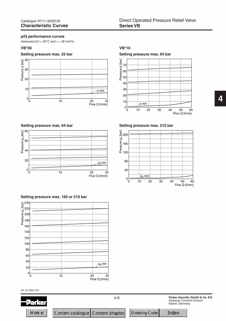
p/Q performance curvesmeasured at t = 50°C and ν = 36 mm²/s
VB*10
Characteristic Curves
Setting pressure max. 160 or 210 bar
Setting pressure max. 25 bar
Setting pressure max. 64 bar Setting pressure max. 210 bar
Setting pressure max. 64 bar
VB*06

4-10
VB_UK.INDD CM
Catalogue HY11-3500/UK
Parker Hannifin GmbH & Co. KGHydraulic Controls DivisionKaarst, Germany
Direct Operated Pressure Relief ValveSeries VB
4
Dimensions
Mounting pattern ISO 5781-03-04-0-00
NG06
Surface finishBolt kit DIN 912 12.9 FPM
SK-M5x30-4pcs7.6 Nm±15%
SK-VB/VM/VS-A06V

4-11
Catalogue HY11-3500/UK
Parker Hannifin GmbH & Co. KGHydraulic Controls DivisionKaarst, Germany
VB_UK.INDD CM
Direct Operated Pressure Relief ValveSeries VB
4
Dimensions
NG10
Surface finishBolt kit DIN 912 12.9 FPM
BK-M10x50-4pcs63 Nm±15%
SK-VB/VM-A10V
Mounting pattern ISO 5781-06-07-0-00

4-12
VB_UK.INDD CM
Catalogue HY11-3500/UK
Parker Hannifin GmbH & Co. KGHydraulic Controls DivisionKaarst, Germany
4
Notes

4-13
Catalogue HY11-3500/UK
Parker Hannifin GmbH & Co. KGHydraulic Controls DivisionKaarst, Germany
VBY_UK.INDD CM
Pilot Operated Pressure Relief ValveSeries VBY
4
Characteristics
Pilot operated relief valves of the series VBY consist of apilot with manual adjustment and a spool type main stage.The valves need to be externally drained.
The series VBY can also be used as pressure sequencevalve, because of the high pressure capability in the outletport and the external drain port.
Features• Subplate mounting acc. to ISO 5781
• Main stage spool type
• Pilot stage seated type
• 4 pressure stages
• 2 adjustment modes
- screw with hexagon socket
- DIN lock
VBY*A06 VBY*A10
VBY*A06 VBY*A10
VBY*A06 VBY*A10
* Port B for remote control, otherwise to be blocked * Port X for remote control, otherwise to be blocked

4-14
VBY_UK.INDD CM
Catalogue HY11-3500/UK
Parker Hannifin GmbH & Co. KGHydraulic Controls DivisionKaarst, Germany
Pilot Operated Pressure Relief ValveSeries VBY
4
Ordering Code / Technical Data
Nominalsize
VBY
Pressuresequence
valve
Pressurestages
Adjustment Seals
Ordering code
Designseries
(not requiredfor ordering)
Technical data
Nominal size NG06 NG10Design Pilo operated sequence valve, spool type
Interface Subplate mounting according to ISO 5781
Mounting position unrestricted
Ambient temperature [°C] -20...+80
Max. operating pressure [bar] P, A, B 315 A, B, X 315
External drain port pressure [bar] T 100 Y 100
Pressure stages [bar] 64, 160, 210, 315
Fluid temperature [°C] -20...+70
Viscosity, recommended [cSt] /permitted [cSt] /
[mm²/s][mm²/s]
30...5020...380
Filtration ISO 4406 (1999) 18/16/13
Nominal flow [l/min] See p/Q curves
Pilot oil flow [cm³/min] approx. 500 approx. 1000
Weight [kg] 2.4 4.5
Code Seals
N NBRV FPM
Code Adjustment
AScrew with
hexagon socket
HTurning knobwith DIN lock
Code Pressure stages
064 up to 64 bar160 up to 160 bar210 up to 210 bar315 up to 315 bar
Code Nominal size
06 NG0610 NG10

4-15
Catalogue HY11-3500/UK
Parker Hannifin GmbH & Co. KGHydraulic Controls DivisionKaarst, Germany
VBY_UK.INDD CM
Pilot Operated Pressure Relief ValveSeries VBY
4
Characteristic Curves
p/Q performance curves VBYmeasured at t = 50°C and ν = 36 mm²/s
NG06
Max. 64 bar NG06 Max. 64 bar NG10
Max. 160 bar NG06
Max. 210 bar NG06
Max. 315 bar NG06
Max. 210 bar NG10
Max. 160 bar NG10
Max. 315 bar NG10
NG10
* for all pressure stages
* for all pressure stages

4-16
VBY_UK.INDD CM
Catalogue HY11-3500/UK
Parker Hannifin GmbH & Co. KGHydraulic Controls DivisionKaarst, Germany
Pilot Operated Pressure Relief ValveSeries VBY
4
Dimensions Dimensions
NG10NG06
Mounting pattern ISO 5781-06-07-0-00
Mounting pattern ISO 5781-03-04-0-00
Surface finishBolt kit DIN 912 12.9 FPM
BK-M5x30-4pcs7.6 Nm±15%
SK-VBY-A06V

4-17
Catalogue HY11-3500/UK
Parker Hannifin GmbH & Co. KGHydraulic Controls DivisionKaarst, Germany
VBY_UK.INDD CM
Pilot Operated Pressure Relief ValveSeries VBY
4
Dimensions
NG10
Mounting pattern ISO 5781-06-07-0-00
Surface finishBolt kit DIN 912 12.9 FPM
BK-M10x50-4pcs63 Nm±15%
SK-VB/VM-A10V

4-18
VBY_UK.INDD CM
Catalogue HY11-3500/UK
Parker Hannifin GmbH & Co. KGHydraulic Controls DivisionKaarst, Germany
4
Notes

Direct Operated Pressure Relief ValveSeries EVSA
4-19
Catalogue HY11-3500/UK
Parker Hannifin GmbH & Co. KGHydraulic Controls DivisionKaarst, Germany
EVSA_UK.INDD CM
4
The direct operated pressure relief valve series EVSA isa seated type valve for screw-in mounting. It is availablein two sizes and three pressure stages.
FunctionWhen the pressure in port P exceeds the setting pressurethe cone opens to port T and thus limits the pressure inport P to the adjusted level.
The integrated damping spool prevents pressure fluctua-tions in the transition region. The pressure is set by theadjusting screw, which is locked by the clamping screw.The setting can optionally be secured by a cylinder lock(DIN lock).
Features• Seated type valve
• Screw-in mounting
• 3 pressure stages
• 2 adjustment modes- screw with lock nut- DIN lock
Characteristics / Ordering Code
Technical data
NoteThe spring must be unloaded when the EVSA is screwedout of the manifold.
Nominalsize / thread
type
EVSA A 1
Pressurerelief valve
Pressurestages
Adjustmentscrew
with hex.socket
FPMSeals
Designseries
(not requiredfor ordering)
Lock
Ordering code
Code Pressure stages
064 up to 64 bar160 up to 160 bar350 up to 350 bar
Code Lock
omit NormalZ DIN lock
Code Nominal size
06 NG06, M28x1.510 NG10, M35x1.5
GeneralDesign Direct operated relief valve, seated typeNominal size NG06 NG10Interface Screw-in mountingMounting position unrestrictedAmbient temperature [°C] -20...+80Weight [kg] 0.3 0.45HydraulicsMax. operating pressure [bar] Port P 350, Port T depressurizedPressure stages [bar] 64, 160, 350Nominal flow [l/min] 40 (NG06), 80 (NG10)Fluid Hydraulic oil according to DIN 51524...525Fluid temperature [°C] Recommended +30...+50, permitted -20...+70Viscosity permitted [cSt] /
recommended [cSt] /[mm²/s][mm²/s]
20...38030...50
Filtration ISO 4406 (1999); 18/16/13

Direct Operated Pressure Relief ValveSeries EVSA
4-20
EVSA_UK.INDD CM
Catalogue HY11-3500/UK
Parker Hannifin GmbH & Co. KGHydraulic Controls DivisionKaarst, Germany
4
Characteristic Curves Dimensions
∆p/Q performance curvesmeasured at t = 50°C and υ = 36 mm²/s
NG06
Pressure stage 64 bar
NG10
Pressure stage 64 bar
Pressure stage 160 bar Pressure stage 160 bar
Pressure stage 350 bar Pressure stage 350 bar

Direct Operated Pressure Relief ValveSeries EVSA
4-21
Catalogue HY11-3500/UK
Parker Hannifin GmbH & Co. KGHydraulic Controls DivisionKaarst, Germany
EVSA_UK.INDD CM
4
Dimensions
EVSA NG10
EVSA NG06
Installation dimensions
Size M D1 D2 D3 D4 D5 L1 L2 L3 L4 L5 L6
NG06 M28 x 1.5 Ø24.8 Ø15 Ø6.8 Ø25H9 Ø6.8 15 19 30 35 45 65
NG10 M35 x 1.5 Ø31.8 Ø18.5 Ø10 Ø32H9 Ø10 18 23 35 41 - 46 52 80
SK-EVSAA0613
SK-EVSAA1013

4-22
EVSA_UK.INDD CM
Catalogue HY11-3500/UK
Parker Hannifin GmbH & Co. KGHydraulic Controls DivisionKaarst, Germany
4
Notes

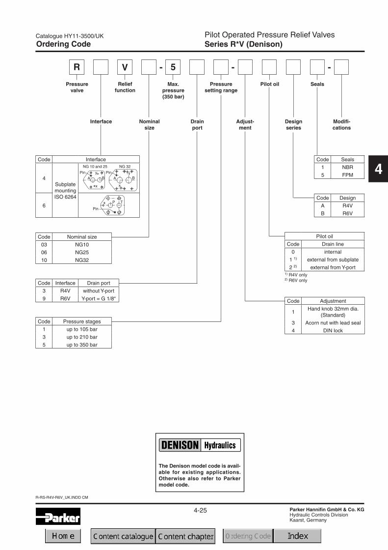
Pilot Operated Pressure Relief ValvesSeries R / RS (Parker), R*V (Denison)
4-23
Catalogue HY11-3500/UK
Parker Hannifin GmbH & Co. KGHydraulic Controls DivisionKaarst, Germany
R-RS-R4V-R6V_UK.INDD CM
4
Pilot operated pressure relief valves are available withboth Parker (series R/RS) and Denison (series R4V/R6V)model codes.
A manually adjusted pilot stage controls a seated typemain stage.
A vent function with a solenoid operated directional valveis available for circulation at minimum pressure.
Features• Pilot operated with manual adjustment• 2 interfaces
- Subplate ISO 6264 (DIN 24340 Form D)with VV01 vent valve
- Subplate ISO 6264 (DIN 24340 Form E)with Cetop 03 vent valve
• 4 pressure stages• 3 adjustment modes
- hand knob- acorn nut with lead seal- DIN lock
• Remote control via port X
Characteristics
Function:Series R
System pressure in port P is applied via the X gallery tothe spring loaded cone in the pilot head. The pilot headcontrols the pressure in the Z area on top of the maincartridge which is additionally kept close by the mainspring.
If the pilot pressure exceeds the setting pressure the pilotcone opens and thus limits the pilot pressure.
When the system pressure exceeds the pilot pressureplus the spring force, the main cartridge opens to port Tand limits the pressure in port P to the adjusted level.
Series RS
Additionally to the relief function of series R, a solenoidoperated vent valve connects the Z area to tank. Thisallows oil circulation from P to T at minimum pressuredrop. The vent valve can either be a standard Cetop 03valves (mounting form E) or a sandwich unit (mountingform D). For both types the vent position can be either atthe energized or de-energized solenoid.
RS25R
R25R RS25R
RS25M
Code 1 Code 9

R-RS-R4V-R6V_UK.INDD CM
4-24
Catalogue HY11-3500/UK
Parker Hannifin GmbH & Co. KGHydraulic Controls DivisionKaarst, Germany
Pilot Operated Pressure Relief ValvesSeries R (Parker)
4
Code Pressure stages
07 up to 70 bar
17 up to 175 bar
25 up to 250 bar
35 up to 350 bar
Code Nominal size
10 NG10
25 NG25
32 NG32
Ordering Code
Adjust-ment
R
Pressurerelief valve
Nominalsize
Pilot oil
S
Poppetspring
Seals
Interface Designseries
(not requiredfor ordering)
Pressurestages
Code Seals
N NBR
V FPM
Code Adjustment
SHand knob(Standard)
L DIN lock
AAcorn nut with
lead seal
Pilot oil
Code Pilot Drain
1 Internal External
4 Internal Internal
Code Interface
R 1)
SubplatemountingISO 6264
M
1) drain line with pipe only
The Parker model code shouldbe used for all new applications.Otherwise also refer to Denisonmodel code.
4-25
Catalogue HY11-3500/UK
Parker Hannifin GmbH & Co. KGHydraulic Controls DivisionKaarst, Germany
R-RS-R4V-R6V_UK.INDD CM
Pilot Operated Pressure Relief ValvesSeries R*V (Denison)
4
Code Pressure stages
1 up to 105 bar
3 up to 210 bar
5 up to 350 bar
Ordering Code
Drainport
R
Pressurevalve
Pilot oil
Designseries
Seals
Interface Modifi-cations
Max.pressure(350 bar)
Code Interface
4SubplatemountingISO 6264
6
Adjust-ment
Relieffunction
V
Nominalsize
Pressuresetting range
5- -
Code Nominal size
03 NG10
06 NG25
10 NG32
Code Interface Drain port
3 R4V without Y-port
9 R6V Y-port = G 1/8“
Pilot oil
Code Drain line
0 internal
1 1) external from subplate
2 2) external from Y-port1) R4V only2) R6V only
Code Adjustment
1Hand knob 32mm dia.
(Standard)
3 Acorn nut with lead seal
4 DIN lock
-
Code Seals
1 NBR
5 FPM
Code Design
A R4V
B R6V
The Denison model code is avail-able for existing applications.Otherwise also refer to Parkermodel code.
R-RS-R4V-R6V_UK.INDD CM
4-26
Catalogue HY11-3500/UK
Parker Hannifin GmbH & Co. KGHydraulic Controls DivisionKaarst, Germany
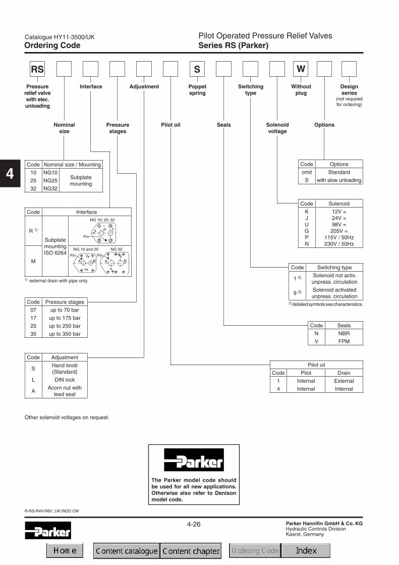
Pilot Operated Pressure Relief ValvesSeries RS (Parker)
4
Ordering Code
RS
Switchingtype
Solenoidvoltage
S
AdjustmentPressurerelief valvewith elec.unloading
Nominalsize
Interface
Pressurestages
Pilot oil
Poppetspring
Seals Options
Withoutplug
W
Code Nominal size / Mounting
10 NG10Subplatemounting
25 NG25
32 NG32
Code Interface
R 1)
SubplatemountingISO 6264
M
1) external drain with pipe only
Code Pressure stages
07 up to 70 bar
17 up to 175 bar
25 up to 250 bar
35 up to 350 bar
Code Solenoid
KJUGPN
12V =24V =98V =205V =
115V / 50Hz230V / 50Hz
Pilot oil
Code Pilot Drain
1 Internal External
4 Internal Internal
2) detailedsymbolsseecharacteristics.
Code Switching type
1 2) Solenoid not activ.unpress. circulation
9 2) Solenoid activatedunpress. circulation
Code Seals
N NBR
V FPM
Other solenoid voltages on request.
Code Options
omit Standard
S with slow unloading
Code Adjustment
SHand knob(Standard)
L DIN lock
AAcorn nut with
lead seal
Designseries
(not requiredfor ordering)
The Parker model code shouldbe used for all new applications.Otherwise also refer to Denisonmodel code.

4-27
Catalogue HY11-3500/UK
Parker Hannifin GmbH & Co. KGHydraulic Controls DivisionKaarst, Germany
R-RS-R4V-R6V_UK.INDD CM
Pilot Operated Pressure Relief ValvesR*V with Vent Function (Denison)
4
Ordering Code
R
Pilot oil
Ventvalve
function
Max.Pressure(350 bar)
Pressurevalve
Interface Nominalsize
Drainport
Pressuresettingrange
Adjust-ment
Designseries
Solenoidvoltage
SealsRelieffunction
Modifi-cations
V 5-
Code Seals
1 NBR
5 FPM
Code Voltage
G0RG0QGARGAGW06W07
12V =24V =98V =
205V =115V / 50 Hz230V / 50 Hz
Code Vent valve
09 3) Solenoid not activ.unpress. circulation
11 4) Solenoid activatedunpress. circulation
3) Solenoid de-energized: open to tankSolenoid energized: vent line blocked
4) Solenoid de-energized: vent line blockedSolenoid energized: open to tank
Pilot oil
Code Drain line
0 internal
1 1) external from subplate
2 2) external from Y-port1) R4V only2) R6V only
Code Adjustment
1 Hand knob (Standard)
3 Acorn nut with lead seal
4 DIN lock
---- -
Designseries
(not requiredor ordering)
Code Interface
4SubplatemountingISO 6264
6
Code Pressure stages
1 up to 105 bar
3 up to 210 bar
5 up to 350 bar
Code Interface Drain port
3 R4V without Y-port
9 R6V Y-port = G 1/8“
Code Nominal size
03 NG10
06 NG25
10 NG32
Code Design
A R4V
B R6V
The Denison model code is avail-able for existing applications.Otherwise also refer to Parkermodel code.

R-RS-R4V-R6V_UK.INDD CM
Pilot Operated Pressure Relief ValvesSeries R / RS (Parker), R*V (Denison)
4-28
Catalogue HY11-3500/UK
Parker Hannifin GmbH & Co. KGHydraulic Controls DivisionKaarst, Germany
4
Technical Data
R / R*V
General
Nominal size 10 25 32Interface Subplate mounting acc. ISO 6264
Mounting position as desired, horizontal mounting prefered
Ambient temperature [°C] -20...+80
Weight Series R*R / R6VSeries R*M / R4V
[kg][kg]
4.52.7
5.84.5
7.86.0
Hydraulic
Max. operating pressure [bar] Ports P (or A) and X up to 350, Port T (or B) and Y depressurized
Pressure stages [bar] 75, 175, 250, 350 (series R) : 105, 210, 350 (series R*V)
Nominal flow Series R*R / R6VSeries R*M / R4V
[l/min][l/min]
250150
500350
650650
Fluid Hydraulic oil according to DIN 51524 ... 525
Viscosity, recommended [cSt] /permitted [cSt] /
[mm²/s][mm²/s]
30 ... 5020 ... 380
Fluid temperature [°C] -20 ... +70
Filtration ISO 4406 - (1999) ; 18/16/13
RS / R*V with vent function
General
Nominal size 10 25 32Interface Subplate mounting acc. ISO 6264
Mounting position as desired, horizontal mounting prefered
Ambient temperature [°C] -20...+80
Weight Series RS*R / R6VSeries RS*M / R4V
[kg][kg]
5.94.4
7.26.2
9.27.7
Hydraulic
Max. operating pressure [bar] Ports P (or A) and X 350, port T (or B) and Y depressurized
Pressure stages [bar] 75, 175, 250, 350 (series R) : 105, 210, 350 (series R*V)
Nominal flow Series RS*R / R6VSeries RS*M / R4V
[l/min][l/min]
250150
500350
650650
Fluid Hydraulic oil according to DIN 51524 ... 525
Viscosity, recommended [cSt] /permitted [cSt] /
[mm²/s][mm²/s]
30 ... 5020 ... 380
Fluid temperature [°C] -20 ... +70
Filtration ISO 4406 - (1999) ; 18/16/13
Electrical
Duty ratio [%] 100 ED; CAUTION: coil temperature up to 180 °C possible
Max. switching frequency [1/h] 16000 (DC), 7200 (AC)
Protection class IP 65 in according with EN 60529 (plugged and mounted)
Code Denison / Code Parker
Supply voltage
Tolerance supply voltage
Power consumption hold
in rush
[V]
[%]
[W]
[W]
G0R / K G0Q / J GAR / U GAG / G W06 / P W07 / N
12V = 24V = 98V = 205V = 150 at 50Hz 230 at 50Hz
+5...-10 +5...-10 +5...-10 +5...-10 +5...-10 +5...-10
31 31 31 31 78 78
31 31 31 31 264 264
Solenoid connection Connector as per EN 175301-803
Wiring min. [mm2] 3 x 1.5 recommended
Wiring length max. [m] 50 recommended

Pilot Operated Pressure Relief ValvesSeries R / RS (Parker), R*V (Denison)
4-29
Catalogue HY11-3500/UK
Parker Hannifin GmbH & Co. KGHydraulic Controls DivisionKaarst, Germany
R-RS-R4V-R6V_UK.INDD CM
4
Characteristic Curves
p/Q performance curveSeries R/RS*R/R6V 1)
p/Q performance curveSeries R/RS*M / R4V 1) Minimum pressure curve
Minimum pressure curve
1) The performance curves are measured with external drain.For internal drain the tank pressure has to be added to curve.

R-RS-R4V-R6V_UK.INDD CM
Pilot Operated Pressure Relief ValvesSeries R / RS (Parker), R*V (Denison)
4-30
Catalogue HY11-3500/UK
Parker Hannifin GmbH & Co. KGHydraulic Controls DivisionKaarst, Germany
4
Dimensions
R*R / R6V
NG ISO-code d1max d2max d3 t3 d4 t4 d5 d610 6264-06-09-*-97 14.7 4.8 7.5 10 M12 20 13.5 20
25 6264-08-13-*-97 23.4 6.3 7.5 10 M16 27 17.5 25
32 6264-10-17-*-97 32 6.3 7.5 10 M18 28 20 30
NG ISO-code Bolt kit - DIN912 12.9 Surface finishNBR FPM
10 6264-06-09-*-97 BK-M12 x 45-4pcs 108 Nm ±15% SK-R10RN50 SK-R10RV50
25 6264-08-13-*-97 BK-M16 x 70-4pcs 264 Nm ±15% SK-R25RN50 SK-R25RV50
32 6264-10-17-*-97 BK-M18 x 75-4pcs 398 Nm ±15% SK-R32RN50 SK-R32RV50
Y: external drain port G 1/8“
NG ISO-code x1 x2 x3 x4 x5 x6 x7 y1 y2 y3 y4 y5 y610 6264-06-09-*-97 53.8 47.5 0 – 22.1 – 22.1 53.8 – 26.9 – – –
25 6264-08-13-*-97 66.7 55.6 23.8 – 11.1 – 33.4 70 – 35 – – –
32 6264-10-17-*-97 88.9 76.2 31.8 – 12.7 – 44.5 82.6 – 41.3 – – –
Tolerance at X and Y pin holes and screw holes ±0.1, at port holes ±0.2.
NG ISO-code B1 B2 H1 H2 H3 H4 H5 H6 L1 L2 L3 L4 L5 L610 6264-06-09-*-97 80 26.9 114 27 88 20.5 25 52.5 118.5 141 180 29.5
25 6264-08-13-*-97 100 35 117.5 45.5 91.5 – 25 12 37.9 124.5 141 – 180 36.5
32 6264-10-17-*-97 120 41.3 123 52 97 26.5 13.5 45 153 141 180 46.5

Pilot Operated Pressure Relief ValvesSeries R / RS (Parker), R*V (Denison)
4-31
Catalogue HY11-3500/UK
Parker Hannifin GmbH & Co. KGHydraulic Controls DivisionKaarst, Germany
R-RS-R4V-R6V_UK.INDD CM
4
RS*R / R6V with vent function
Dimensions
NG ISO-code x1 x2 x3 x4 x5 x6 x7 y1 y2 y3 y4 y5 y610 6264-06-09-*-97 53.8 47.5 0 – 22.1 – 22.1 53.8 – 26.9 – – –
25 6264-08-13-*-97 66.7 55.6 23.8 – 11.1 – 33.4 70 – 35 – – –
32 6264-10-17-*-97 88.9 76.2 31.8 – 12.7 – 44.5 82.6 – 41.3 – – –
Tolerance at X and Y pin holes and screw holes ±0.1, at port holes ±0.2.
NG ISO-code B1 B2 H1 H2 H3 H4 H5 H6 L1 L2 L3 L4 L5 L610 6264-06-09-*-97 80 26.9 206 27 88 136.5 25 12 52.5 118.5 163.8 180 36.5
25 6264-08-13-*-97 100 35 210 45.5 91.5 140 25 12 37.9 124.5 163.8 – 180 36.5
32 6264-10-17-*-97 120 41.3 215.5 52 97 145.5 25 12 45 153 163.8 180 36.5
NG ISO-code d1max d2max d3 t3 d4 t4 d5 d610 6264-06-09-*-97 14.7 4.8 7.5 10 M12 20 13.5 20
25 6264-08-13-*-97 23.4 6.3 7.5 10 M16 27 17.5 25
32 6264-10-17-*-97 32 6.3 7.5 10 M18 28 20 30
Y: external drain port G 1/8“
NG ISO-code Bolt kit - DIN912 12.9 Surface finishNBR FPM
10 6264-06-09-*-97 BK-M12 x 45-4pcs 108 Nm ±15% SK-RS10RN50 SK-RS10RV50
25 6264-08-13-*-97 BK-M16 x 70-4pcs 264 Nm ±15% SK-RS25RN50 SK-RS25RV50
32 6264-10-17-*-97 BK-M18 x 75-4pcs 398 Nm ±15% SK-RS32RN50 SK-RS32RV50

R-RS-R4V-R6V_UK.INDD CM
Pilot Operated Pressure Relief ValvesSeries R / RS (Parker), R*V (Denison)
4-32
Catalogue HY11-3500/UK
Parker Hannifin GmbH & Co. KGHydraulic Controls DivisionKaarst, Germany
4
Dimensions
NG ISO-code x1 x2 x3 x4 x5 x6 x7 y1 y2 y3 y4 y5 y610 6264-06-07-*-97 42.9 35.8 21.5 – 7.2 21.5 0 66.7 58.8 33.4 7.9 14.3 –
25 6264-08-11-*-97 60.3 49.2 39.7 – 11.1 20.6 0 79.4 73 39.7 6.4 15.9 –
32 6264-10-15-*-97 84.2 67.5 59.5 42.1 16.7 24.6 0 96.8 92.8 48.4 3.8 21.4 –
NG ISO-code B1 B2 H1 H2 H3 H4 H5 H6 L1 L2 L3 L4 L5 L610 6264-06-07-*-97 87.3 33.35 83 21 – – 62.5 – 29 94.8 – 143 181 144.8
25 6264-08-11-*-97 105 39.7 109.5 29 – – 89 – 34.7 126.8 – 143 181 144.8
32 6264-10-15-*-97 120 48.4 120 29 – – 99.5 – 30.6 144.3 – 143 181 144.8
NG ISO-code d1max d2max d3 t3 d4 t4 d5 d610 6264-06-07-*-97 15 7 7.1 8 M10 16 10.8 17
25 6264-08-11-*-97 23.4 7.1 7.1 8 M10 18 10.8 17
32 6264-10-15-*-97 32 7.1 7.1 8 M10 20 10.8 17
Tolerance at X and Y pin holes and screw holes ±0.1, at port holes ±0.2.
R*M / R4V
NG ISO-code Bolt kit - DIN912 12.9 Surface finishNBR FPM
10 6264-06-07-*-97 BK-M10 x 35-4pcs 63 Nm ±15% SK-R10MN50 SK-R10MV50
25 6264-08-11-*-97 BK-M10 x 45-4pcs 63 Nm ±15% SK-R25MN50 SK-R25MV50
32 6264-10-15-*-97 BK-M10 x 45-6pcs 63 Nm ±15% SK-R32MN50 SK-R32MV50

Pilot Operated Pressure Relief ValvesSeries R / RS (Parker), R*V (Denison)
4-33
Catalogue HY11-3500/UK
Parker Hannifin GmbH & Co. KGHydraulic Controls DivisionKaarst, Germany
R-RS-R4V-R6V_UK.INDD CM
4
RS*M / R4V with vent function
Dimensions
NG ISO-code x1 x2 x3 x4 x5 x6 x7 y1 y2 y3 y4 y5 y610 6264-0-07-*-97 42.9 35.8 21.5 – 7.2 21.5 0 66.7 58.8 33.4 7.9 14.3 –
25 6264-08-11-*-97 60.3 49.2 39.7 – 11.1 20.6 0 79.4 73 39.7 6.4 15.9 –
32 6264-10-15-*-97 84.2 67.5 59.5 42.1 16.7 24.6 0 96.8 92.8 48.4 3.8 21.4 –
NG ISO-code B1 B2 B3 H1 H2 H3 H4 H6 L1 L2 L3 L4 L5 L6 L710 6264-06-07-*-97 87.3 33.35 70 130 21 68.5 109.5 – 29 94.8 – 143 181 165.6 144.8
25 6264-08-11-*-97 105 39.7 70 156.5 29 95 136 – 34.7 126.8 – 143 181 165.6 144.8
32 6264-10-15-*-97 120 48.4 70 167 29 105.5 146.5 – 30.6 144.3 – 143 181 165.6 144.8
NG ISO-code d1max d2max d3 t3 d4 t4 d5 d6
10 6264-06-07-*-97 15 7 7.1 8 M10 16 10.8 17
25 6264-08-11-*-97 23.4 7.1 7.1 8 M10 18 10.8 17
32 6264-10-15-*-97 32 7.1 7.1 8 M10 20 10.8 17
Tolerance at X and Y pin holes and screw holes ±0.1, at port holes ±0.2.
NG ISO-code Bolt kit - DIN912 12.9 Surface finishNBR FPM
10 6264-06-07-*-97 BK-M10 x 35-4pcs 63 Nm ±15% SK-RS10MN50 SK-RS10MV50
25 6264-08-11-*-97 BK-M10 x 45-4pcs 63 Nm ±15% SK-RS25MN50 SK-RS25MV50
32 6264-10-15-*-97 BK-M10 x 45-6pcs 63 Nm ±15% SK-RS32MN50 SK-RS32MV50

R-RS-R4V-R6V_UK.INDD CM
4-34
Catalogue HY11-3500/UK
Parker Hannifin GmbH & Co. KGHydraulic Controls DivisionKaarst, Germany
4
Notes

Pilot Operated Pressure Relief ValveSeries DSDU
4-35
Catalogue HY11-3500/UK
Parker Hannifin GmbH & Co. KGHydraulic Controls DivisionKaarst, Germany
DSDU_UK.INDD CM
4
Characteristics / Technical Data
The pilot operated pressure relief valves series DSDUlimit the system pressure by opening the pressure portto the tank. They are mostly used for accumulator pres-sure relief. The valve is set and sealed by the Germantechnical monitoring association TÜV.The valve deliveryincludes a copy of the TÜV certificate.
Features• TÜV certificate
• Subplate mounting acc. to ISO 6264
• Nominal size 25
• Remote control via port X
DSDU*P20
Other TÜV approved pressure relief valves on request.
GeneralSize 25
Interface Subplate mounting according to ISO 6264
Mounting position as desired, horizontal mounting prefered
Ambient temperature [°C] -20...+80
Weight [kg] 4.5
HydraulicMax. operating pressure [bar] Ports A and X 350, B and Y depressurized
Pilot Internal / internal
Adjustment pressure [bar] See ordering code
Nominal flow [l/min] See ordering code
Fluid Hydraulic oil according to DIN 51524 ... 525
Viscosity, recommended [cSt] /permitted [cSt] /
[mm²/s][mm²/s]
30 ... 5012 ... 230
Fluid temperature [°C] -5 ... +70
Filtration ISO 4406 (1999), 18/16/13
Technical data

Pilot Operated Pressure Relief ValveSeries DSDU
4-36
DSDU_UK.INDD CM
Catalogue HY11-3500/UK
Parker Hannifin GmbH & Co. KGHydraulic Controls DivisionKaarst, Germany
4
p/Q curve
Ordering Code / p/Q Curve
Ordering code
Ordering Examples
DSDU 578 P20 - 120bar matches Qmax 240 l/min, opening pressure 120bar
DSDU P578 P20 - 150bar matches Qmax 265 l/min, opening pressure 150bar
Code Seals
omit NBRV FPM
Seals
DSDU TÜV
Pressurelimitingvalve
Desired openingpressure in bar(please specify)
Typecode
Pressurestage
Type Code 578 P20Pressure
stage
Openingpressure ranges
[bar]Qmax [l/min] depending.on opening pressure
220 B 50 - 75
240265
E76 - 125126 - 175
300320
G176 - 200201 - 250
345370
K251 - 300301 - 350

Pilot Operated Pressure Relief ValveSeries DSDU
4-37
Catalogue HY11-3500/UK
Parker Hannifin GmbH & Co. KGHydraulic Controls DivisionKaarst, Germany
DSDU_UK.INDD CM
4
DSDU*P20
Dimensions
Mounting pattern ISO 6264-08-11-*-97
Tolerance at pin holes and screw holes ±0.1, at port holes ±0.2.
Size Bolt kit - DIN 912 12.9NBR FPM
P20 BK-M10 x 40-4pcs63 Nm±15%
SK-DSDU5P20 SK-DSDU5P20V

4-38
DSDU_UK.INDD CM
Catalogue HY11-3500/UK
Parker Hannifin GmbH & Co. KGHydraulic Controls DivisionKaarst, Germany
4
Notes

4-39
Catalogue HY11-3500/UK
Parker Hannifin GmbH & Co. KGHydraulic Controls DivisionKaarst, Germany
RE06MW-4VP01_UK.INDD CM
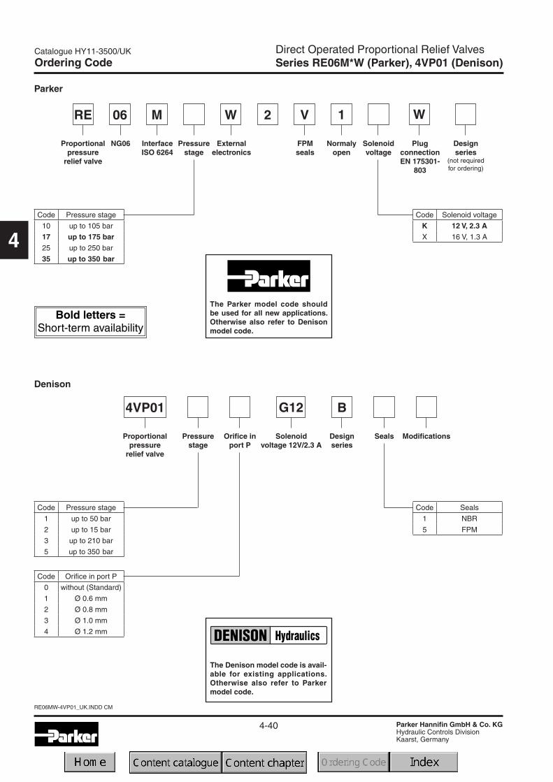
Direct Operated Proportional Relief ValvesSeries RE06M*W (Parker), 4VP01 (Denison)
4
Characteristics / Technical Data
Direct operated proportional pressure relief valves areavailable with both Parker (series RE06M*W) and Deni-son (series 4VP01) model codes.
FunctionWhen the pressure in port P (or A for RE06*M) exeeds thepressure setting at the solenoid, the cone opens to port Tand limits the pressure in port P to the adjusted level.The optimum performance can be achieved in combina-tion with the digital amplifier module PCD00A-400.
Features• Direct operated by proportional solenoid• Very low pressure adjustment of pmin
• 2 pressure ports, A and P for RE06M*W• 1 pressure port for 4VP01• Subplate mounting according to ISO 6264• 4 pressure stages
NoteThe RE06M*W series is equipped with two pressure ports(port P and A).The solenoid is located on the B port sideof the mounting pattern.
The 4VP01 series is equipped with one pressure port(port P).The solenoid is located on the A port side of themounting pattern.
Technical data
GeneralNominal size DIN NG06 / CETOP03 / NFPA D03
Interface Subplate mounting according to ISO 6264
Mounting position as desired, horizontale mounting prefered
Ambient temperature [°C] -20 ... +70
Weight [kg] 1.8
HydraulicMax. operating pressure [bar] Ports P (and A) up to 350; port T depressurized
Pressure stages [bar] 105, 175, 250, 350
Nominal flow [l/min] See p/Q curves
Fluid Hydraulic oil as per DIN 51524 ... 525
Viscosity, recommended [cSt] /permitted [cSt] /
[mm²/s][mm²/s]
30 ... 8012 ... 380
Fluid temperature [°C] -20 ... +60
Filtration ISO 4406 (1999), 18/16/13
Linearity [%] ±2.8
Repeatability [%] <±1
Hysteresis [%] ±1.5 of pmax
ElectricalDuty ratio [%] 100 ED
Protection class IP 65 in accordance with EN 60529 (plugged and mounted)
Nominal voltage [V] 12 (2.3 A max. current), 16 (1.3 A max. current)
Coil resistance [Ohm] 4 at 20°C
Solenoid connection Connector as per EN 175301-803
Power amplifier, recommended PCD00A-400
RE06M*W
Port A onlyfor RE06M*W
RE06M*W
4-40
RE06MW-4VP01_UK.INDD CM
Catalogue HY11-3500/UK
Parker Hannifin GmbH & Co. KGHydraulic Controls DivisionKaarst, Germany
Direct Operated Proportional Relief ValvesSeries RE06M*W (Parker), 4VP01 (Denison)
4
Ordering Code
p/Q curPressure sta
FPMseals
Pressurestage
Solenoidvoltage
PlugconnectionEN 175301-
803
W1W 2RE M06 V
Designseries
(not requiredfor ordering)
Normalyopen
Code Pressure stage
10 up to 105 bar
17 up to 175 bar25 up to 250 bar
35 up to 350 bar
Externalelectronics
InterfaceISO 6264
NG06Proportionalpressure
relief valve
Code Solenoid voltage
K 12 V, 2.3 AX 16 V, 1.3 A
SealsPressurestage
Orifice inport P
Solenoidvoltage 12V/2.3 A
G12 B4VP01
Designseries
Code Pressure stage
1 up to 50 bar
2 up to 15 bar
3 up to 210 bar
5 up to 350 bar
Proportionalpressure
relief valve
Code Seals
1 NBR
5 FPM
Modifications
Code Orifice in port P
0 without (Standard)
1 Ø 0.6 mm
2 Ø 0.8 mm
3 Ø 1.0 mm
4 Ø 1.2 mm
Denison
Parker
The Denison model code is avail-able for existing applications.Otherwise also refer to Parkermodel code.
The Parker model code shouldbe used for all new applications.Otherwise also refer to Denisonmodel code.

4-41
Catalogue HY11-3500/UK
Parker Hannifin GmbH & Co. KGHydraulic Controls DivisionKaarst, Germany
RE06MW-4VP01_UK.INDD CM
Direct Operated Proportional Relief ValvesSeries RE06M*W (Parker), 4VP01 (Denison)
4
p/Q curvesPressure stage 105bar
Characteristic Curves
Pressure stage 350bar
Min. adjusted pressurePressure stage 105bar
Pressure/signal curvePressure stage 105bar Pressure stage 350bar
Pressure stage 350bar

4-42
RE06MW-4VP01_UK.INDD CM
Catalogue HY11-3500/UK
Parker Hannifin GmbH & Co. KGHydraulic Controls DivisionKaarst, Germany
Direct Operated Proportional Relief ValvesSeries RE06M*W (Parker), 4VP01 (Denison)
4
Mounting pattern ISO 6264-03-04-*-97
Dimensions
RE06M*W
Surface finish Bolt kit - DIN 912 12.9NBR FPM
BK-4xM5x30-4pcs7.6 Nm±15%
SK-RE06MNW SK-RE06MVW
4VP01
RE06M*W:Port B: O-ring recess diameteron valve body.
4VP01:Without ports A and B

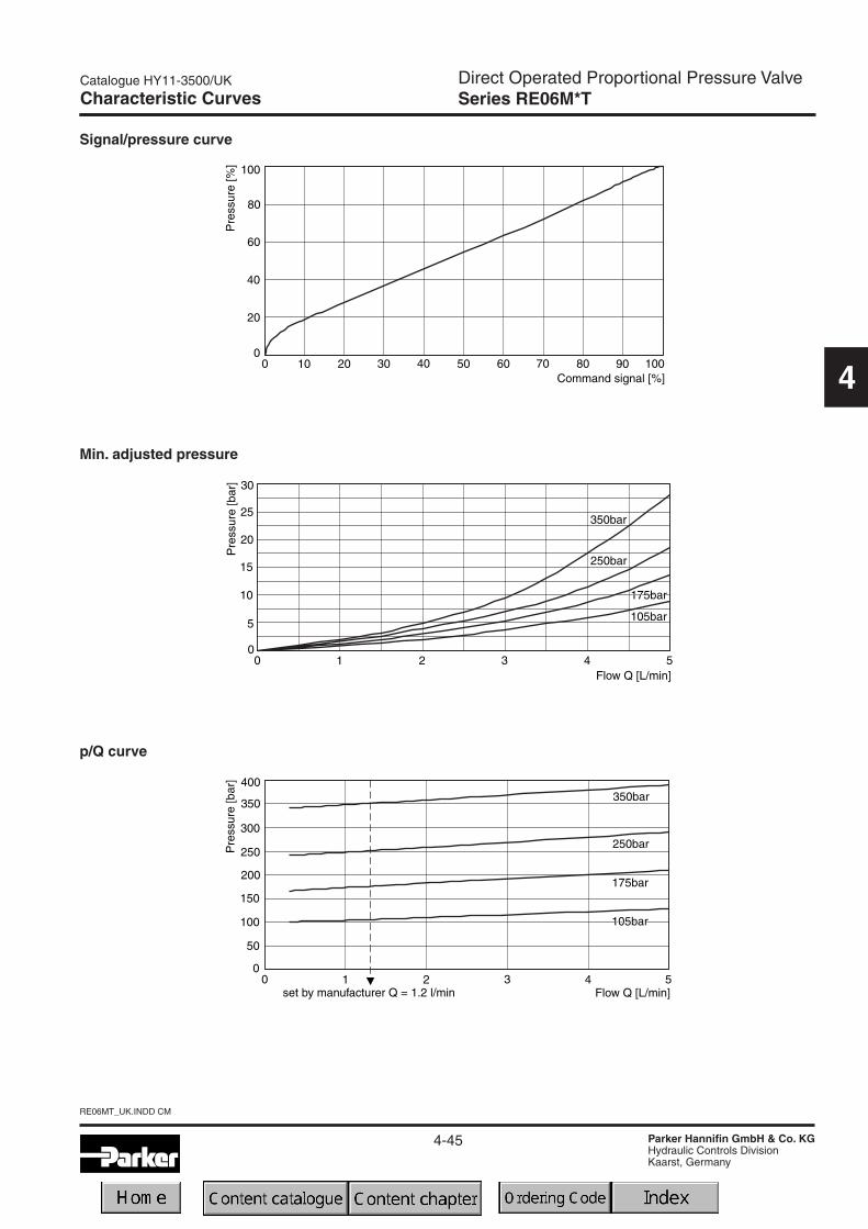
Direct Operated Proportional Pressure ValveSeries RE06M*T
4-43
Catalogue HY11-3500/UK
Parker Hannifin GmbH & Co. KGHydraulic Controls DivisionKaarst, Germany
RE06MT_UK.INDD CM
4
Characteristics / Ordering Code
The proportional pressure relief valve series RE06M*T isdirect operated seated type valve for subplate mountingwith on-board electronics.
FunctionWhen the pressure in port P or A exeeds the pressuresetting at the solenoid, the cone opens to port T and limitsthe inlet pressure to the adjusted level.
The pressure adjustment is effected by applying currentto the solenoid. The control signal is modulated to thesolenoid current by the electronics.
Features• Direct operated pressure relief valve
• Onboard electronics
• Ramp line adjustment
• Characteristics linearized
• Very low pressure adjustment of pmin
• Subplate mounting acc. to ISO 6264
• 4 pressure stages
• 2 pressure inlet ports A and P
FPMseals
Pressurestages
Commandsignal
Electronicattachment
01T 2RE M06 V
Designseries
(not requiredfor ordering)
Normalyopen
Code Pressure stages
10 105bar
17 175bar25 250bar
35 350bar
Onboardelectronics
InterfaceISO 6264
NG06Proportionalpressure
relief valve
Ordering code
Code Command signal
F
Voltage input0...+10V with
reference output+10V
GCurrent input
0...20mA

Direct Operated Proportional Pressure ValveSeries RE06M*T
4-44
RE06MT_UK.INDD CM
Catalogue HY11-3500/UK
Parker Hannifin GmbH & Co. KGHydraulic Controls DivisionKaarst, Germany
4
Technical Data
GeneralNominal size DIN NG06 / CETOP03 / NFPA D03
Interface Subplate mounting according to ISO 6264
Mounting position as desired, horizontal mounting prefered
Ambient temperature [°C] -20...+80
Weight [kg] 2.2
HydraulicMax. operating pressure [bar] Ports A and P 350, connection T depressurized
Pressure stages [bar] 105, 175, 250, 350
Nominal flow [l/min] See p/Q curves
Fluid Hydraulic oil according to DIN 51524 ... 525
Viscosity,recommended [cSt] /permitted [cSt] /
[mm²/s][mm²/s]
30 ... 8012 ... 380
Fluid temperature [°C] -20 ... +60
Filtration ISO 4406 (1999), 18/16/13
Linearity [%] See curve
Repeatability [%] <±1
Hysteresis [%] ±1.5 of pmax
ElectricalDuty ratio [%] 100 ED
Protection class IP65 according to EN 60529 (plugged and mounted)
Supply voltage [V] 14.5...30
Ripple in supply voltage [%] max. 5
Current consumption [A] 2.8
Input range
voltage input [V] 0...+10 max. / 10kOhm
current input [mA] 0...+20 / 500Ohm
Adjustment range of ramp time [s] 0...5
Installation cross-section Min. 1mm² shielded
Cable length [m] Max. 50
Electrical connection No. 5004072; 6pole + PE / connector EN 175201-804 / cableØ 8...10mm
Direct Operated Proportional Pressure ValveSeries RE06M*T
4-45
Catalogue HY11-3500/UK
Parker Hannifin GmbH & Co. KGHydraulic Controls DivisionKaarst, Germany
RE06MT_UK.INDD CM
4
Signal/pressure curve
Characteristic Curves
Min. adjusted pressure
p/Q curve
Direct Operated Proportional Pressure ValveSeries RE06M*T
4-46
RE06MT_UK.INDD CM
Catalogue HY11-3500/UK
Parker Hannifin GmbH & Co. KGHydraulic Controls DivisionKaarst, Germany
4
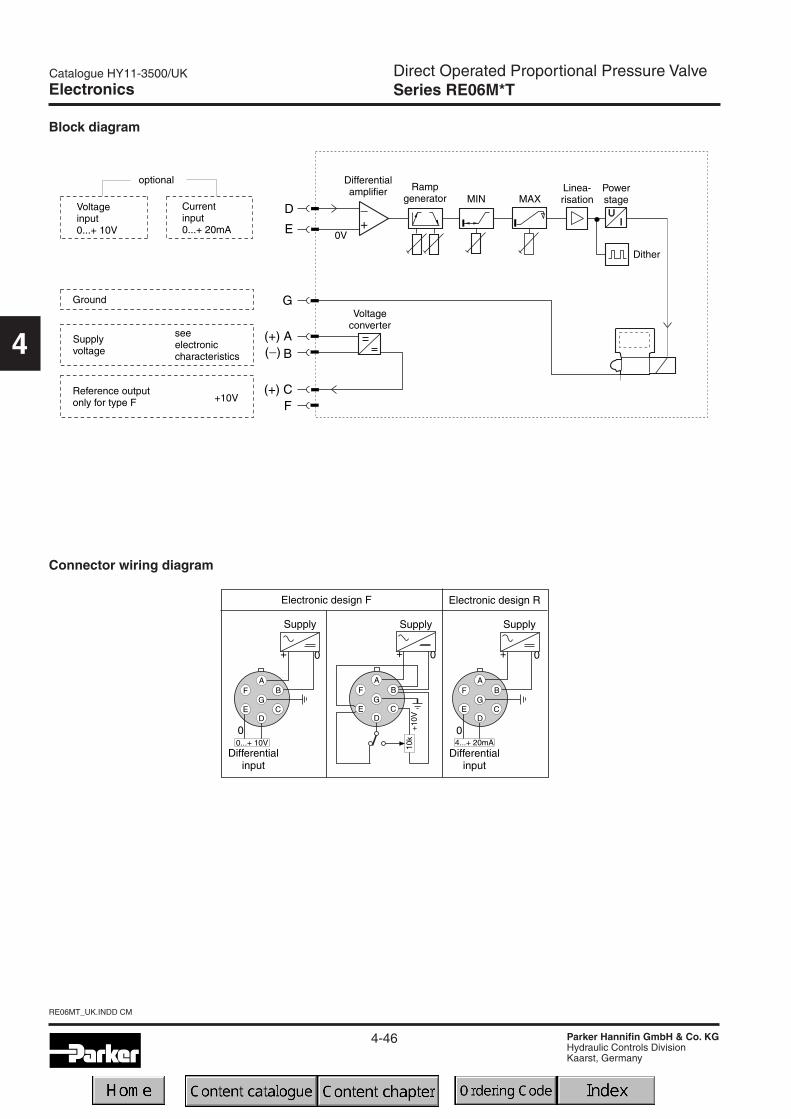
Block diagram
Connector wiring diagram
Electronics

Direct Operated Proportional Pressure ValveSeries RE06M*T
4-47
Catalogue HY11-3500/UK
Parker Hannifin GmbH & Co. KGHydraulic Controls DivisionKaarst, Germany
RE06MT_UK.INDD CM
4
Mounting pattern ISO 6264-03-04-*-97
Dimensions
Surface finish Bolt kit - DIN 912 12.9NBR FPM
BK-M5x30-4pcs7.6 Nm±15%
SK-RE06MNT SK-RE06MVT
Port B:
O-ring recess diameteron valve body.

4-48
RE06MT_UK.INDD CM
Catalogue HY11-3500/UK
Parker Hannifin GmbH & Co. KGHydraulic Controls DivisionKaarst, Germany
4
Notes

4-49
Catalogue HY11-3500/UK
Parker Hannifin GmbH & Co. KGHydraulic Controls DivisionKaarst, Germany
REW_R4V-R6V_UK.INDD CM
Pilot Operated Pressure Relief ValvesSeries RE*W (Parker), R*V (Denison)
4
Characteristics
Proportional pressure relief valves for external electronicsare available with both Parker (series RE*W) and Denison(series R*V) model codes.
A proportionally adjusted pilot stage controls a seatedtype main stage.The valves are equipped with a mechani-cal maximum pressure stage (optional for RE*R*W).
The optimum performance can be achieved in combina-tion with the digital amplifier module PCD00A-400.
Features• Pilot operated with proportional solenoid
• Continuous adjustment by proportional solenoid
• 2 interfaces: subplate, ISO 6264 (DIN 24340 Form D+ Form E)
• 4 pressure stages
• Optional mechanical maximum pressure adjustment(for RE*R*W)
RE*R*W RE*M*W
RE25M*WRE25R*W
mechanicalmaximumpressureadjustment

4-50
REW_R4V-R6V_UK.INDD CM
Catalogue HY11-3500/UK
Parker Hannifin GmbH & Co. KGHydraulic Controls DivisionKaarst, Germany
Pilot Operated Pressure Relief ValveSeries RE*W (Parker)
4
Ordering Code
W 1 WRE S
Normalyopen
Solenoidvoltage
Off-boardelectronics
Proportionalpressure
relief valve
Nominalsize
Interface
Pressurestages
Pilot oil
Poppetspring
Seals Options
Withoutplug
Designseries
(not requiredfor ordering)
Code Nominal size
10 NG10
25 NG25
32 NG32
Code Interface
R 1)
SubplatemountingISO 6264
M
1) external drain with pipe only
Pilot oil
Code Pilot Drain
1 Internal External
4 Internal Internal
Code Seals
N NBR
V FPM
2) not for R*M
Code Pressure stages
10 up to 105 bar
17 up to 175 bar
25 up to 250 bar
35 up to 350 bar
Code Options
omit 2) Standard
M Mech. max. adjust.
Code Solenoid
K 12V, 2.3A
X 16V, 1.3A
The Parker model code shouldbe used for all new applications.Otherwise also refer to Denisonmodel code.

4-51
Catalogue HY11-3500/UK
Parker Hannifin GmbH & Co. KGHydraulic Controls DivisionKaarst, Germany
REW_R4V-R6V_UK.INDD CM
Pilot Operated Pressure Relief ValvesSeries R*V (proportional) (Denison)
4
Ordering Code
R
Pilot oil
Options
Max.Pressure(350 bar)
Pressurevalve
Interface Nominalsize
Drainport
Pressurestages
Mechanicaladjustment
Designseries
Solenoidvoltage
12V/2.3A
A
SealsRelieffunction
Modifi-cations
V 5-
Code Options
P2With mech. max.
adjustment
PS 4) w/o mech. max.adjustment
4) not for R4V
Pilot oil
Code Drain line
0 internal
1 2) external fromsubplate
2 3) external Y-port2) R4V only3) R6V only
Code InterfaceMechanicaladjustment
P 1) R6VHexagon screw
with lock nut
1 R4V Hand knob
3 R4VAcorn nut with
lead seal1) Use code P also for valve w/o mechanical
adjustment
Code Nominal size
03 NG10
06 NG25
10 NG32
Code Interface Drain port
3 R4V without Y-port
9 R6V Y-port = G 1/8“
Code Seals
1 NBR
5 FPM
Code Pressure stages
1 up to 105 bar
3 up to 210 bar
5 up to 350 bar
---- -
Code Interface
4SubplatemountingISO 6264
6
The Denison model code is avail-able for existing applications.Otherwise also refer to Parkermodel code.

4-52
REW_R4V-R6V_UK.INDD CM
Catalogue HY11-3500/UK
Parker Hannifin GmbH & Co. KGHydraulic Controls DivisionKaarst, Germany
Pilot Operated Pressure Relief ValvesSeries RE*W (Parker), R*V (Denison)
4
GeneralNominal size 10 25 32Interface Subplate mounting acc. ISO 6264
Mounting position as desired, horizontal mounting prefered
Ambient temperature [°C] -20...+80
Weight Series RE*R [kg] 5.2 6.4 8.3
Series RE*M [kg] 4.5 6.3 7.8
Series RE*E [kg] — — —
HydraulicMax. operating pressure [bar] Ports P (or A) and X 350, port T (or B), B and Y depressurized
Pressure stages [bar] 105, 175, 250, 350 (series RE*W), 105, 210, 350 (series R*V)
Nominal flow Series RE*R [l/min] 250 500 650
Series RE*M [l/min] 150 350 650
Fluid Hydraulic oil according to DIN 51524 ... 525
Viscosity, recommended [cSt] /permitted [cSt] /
[mm²/s][mm²/s]
30 ... 5020 ... 380
Fluid temperature [°C] -20 ... +70
Filtration ISO 4406 (1999); 18/16/13
Electrical (prop. solenoid)Duty ratio [%] 100 ED
Protection class IP65 in accordance with EN 60529 (plugged and mounted)
Nominal voltage [V] 12 (max. current 2.3A), 16 (max. current 1.3A)
Coil resistance [Ohm] 4 at 20°C
Solenoid connectors Connector as per EN 175301-803
Power amplifier, recommended PCD00A-400
RE*W
Technical Data

4-53
Catalogue HY11-3500/UK
Parker Hannifin GmbH & Co. KGHydraulic Controls DivisionKaarst, Germany
REW_R4V-R6V_UK.INDD CM
Pilot Operated Pressure Relief ValvesSeries RE*W (Parker), R*V (Denison)
4
Characteristic Curves
RE*R*W/R6VSignal/pressure curve
p/Q performance curves 1)
Minimum pressure curves 1)
1) The performance curves are measured with external drain.For internal drain the tank pressure has to be added to curve.

4-54
REW_R4V-R6V_UK.INDD CM
Catalogue HY11-3500/UK
Parker Hannifin GmbH & Co. KGHydraulic Controls DivisionKaarst, Germany
Pilot Operated Pressure Relief ValvesSeries RE*W (Parker), R*V (Denison)
4
p/Q performance curves 1)
Minimum pressure curves 1)
Characteristic Curves
RE*M*W/R4VSignal/pressure curve
1) The performance curves are measured with external drain.For internal drain the tank pressure has to be added to curve.

4-55
Catalogue HY11-3500/UK
Parker Hannifin GmbH & Co. KGHydraulic Controls DivisionKaarst, Germany
REW_R4V-R6V_UK.INDD CM
Pilot Operated Pressure Relief ValvesSeries RE*W (Parker), R*V (Denison)
4
NG ISO-code B1 B2 H1 H2 H3 H4 H5 H6 L1 L2 L3 L4 L5 L610 6264-06-09-*-97 80 26.9 158.7 27 88 – 20.5 25 52.5 118.5 182.3 14.4 29.5
25 6264-08-13-*-97 100 35 161.2 45.5 91.5 – 25 12 37.9 124.5 182.3 14.4 – 36.5
32 6264-10-17-*-97 120 41.3 166.7 52 97 – 26.5 13.5 45 153 182.3 14.4 46.5
NG ISO-code d1max d2max d3 t3 d4 t4 d5 d610 6264-06-09-*-97 14.7 4.8 7.5 10 M12 20 13.5 20
25 6264-08-13-*-97 23.4 6.3 7.5 10 M16 27 17.5 25
32 6264-10-17-*-97 32 6.3 7.5 10 M18 28 20 30
RE*R*W/R6V
Dimensions
NG ISO-code x1 x2 x3 x4 x5 x6 x7 y1 y2 y3 y4 y5 y610 6264-06-09-*-97 53.8 47.5 0 – 22.1 – 22.1 53.8 – 26.9 – – –
25 6264-08-13-*-97 66.7 55.6 23.8 – 11.1 – 33.4 70 – 35 – – –
32 6264-10-17-*-97 88.9 76.2 31.8 – 12.7 – 44.5 82.6 – 41.3 – – –
Tolerance at X and Y pin holes and screw holes ±0.1, at port holes ±0.2.
Y: external drain port G 1/8“
NG ISO-code Bolt kit - DIN912 12.9 Surface finishNBR FPM
10 6264-06-09-*-97 BK-M12 x 45-4pcs 108 Nm ±15% SK-RE10RN50 SK-RE10RV50
25 6264-08-13-*-97 BK-M16 x 70-4pcs 264 Nm ±15% SK-RE25RN50 SK-RE25RV50
32 6264-10-17-*-97 BK-M18 x 75-4pcs 398 Nm ±15% SK-RE32RN50 SK-RE32RV50

4-56
REW_R4V-R6V_UK.INDD CM
Catalogue HY11-3500/UK
Parker Hannifin GmbH & Co. KGHydraulic Controls DivisionKaarst, Germany
Pilot Operated Pressure Relief ValvesSeries RE*W (Parker), R*V (Denison)
4
RE*M*W
NG ISO-code d1max d2max d3 t3 d4 t4 d5 d610 6264-06-07-*-97 15 7 7.1 8 M10 16 10.8 17
25 6264-08-11-*-97 23.4 7.1 7.1 8 M10 18 10.8 17
32 6264-10-15-*-97 32 7.1 7.1 8 M10 20 10.8 17
Dimensions
NG ISO-code B1 B2 B3 H1 H2 H3 H4 H6 L1 L2 L3 L4 L5 L610 6264-06-07-*-97 87.3 33.35 71 130 21 68.5 109.5 – 29 94.8 – 143 144.8 164.8
25 6264-08-11-*-97 105 39.7 71 156.5 29 95 136 – 34.7 126.8 – 143 144.8 164.8
32 6264-10-15-*-97 120 48.4 71 167 29 105.5 146.5 – 30.6 144.3 – 143 144.8 164.8
NG ISO-code x1 x2 x3 x4 x5 x6 x7 y1 y2 y3 y4 y5 y610 6264-06-07-*-97 42.9 35.8 21.5 – 7.2 21.5 0 66.7 58.8 33.4 7.9 14.3 –
25 6264-08-11-*-97 60.3 49.2 39.7 – 11.1 20.6 0 79.4 73 39.7 6.4 15.9 –
32 6264-10-15-*-97 84.2 67.5 59.5 42.1 16.7 24.6 0 96.8 92.8 48.4 3.8 21.4 –
Tolerance at X and Y pin holes and screw holes ±0.1, at port holes ±0.2.
NG ISO-code Bolt kit - DIN912 12.9 Surface finishNBR FPM
10 6264-06-07-*-97 BK-M10 x 35-4pcs 63 Nm ±15% SK-RE10MN50 SK-RE10MV50
25 6264-08-11-*-97 BK-M10 x 45-4pcs 63 Nm ±15% SK-RE25MN50 SK-RE25MV50
32 6264-10-15-*-97 BK-M10 x 45-4pcs 63 Nm ±15% SK-RE32MN50 SK-RE32MV50

4-57
Catalogue HY11-3500/UK
Parker Hannifin GmbH & Co. KGHydraulic Controls DivisionKaarst, Germany
RET_R4V-R6V_UK.INDD CM
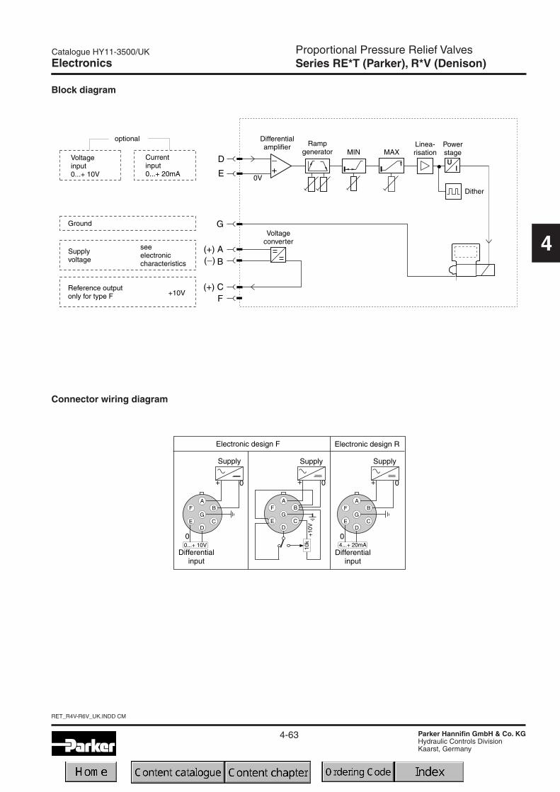
Proportional Pressure Relief ValvesSeries RE*T (Parker), R*V (Denison)
4
Characteristics
RE25M*T
Proportional pressure relief valves with onboard elec-tronics are available with both Parker (series RE*T) andDenison (series R*V) model codes.
The proportional solenoid operated pilot stage with inte-grated electronics controls a seated type main stage.
Features• Pilot operated pressure relief valve
• Onboard electronics
• Factory set
• Ramp time adjustment
• Linearized characteristics
• 4 pressure stages
• 2 interfaces: subplate, ISO 6264 (DIN 24340 Form D+ Form E)
• Optional mechanical maximum pressure adjustment
R25R*T

RET_R4V-R6V_UK.INDD CM
4-58
Catalogue HY11-3500/UK
Parker Hannifin GmbH & Co. KGHydraulic Controls DivisionKaarst, Germany
Proportional Pressure Relief ValvesSeries RE*T (Parker)
4
Ordering Code
Commandsignal
Pressurerelief valvewith elec.unloading
Electronicattach-ments
SRE 01T
Normalyopen
On-boardelectronics
Nominalsize
Interface
Pressurestages
Pilot oil
Poppetspring
Seals Options
Designseries
(not requiredfor ordering)
Code Nominal size
10 NG10
25 NG25
32 NG32
Code Interface
R 1)
SubplatemountingISO 6264
M
1) external drain with pipe only
Code Pressure stages
10 up to 105 bar
17 up to 175 bar
25 up to 250 bar
35 up to 350 bar
Code Options
omit Standard
M Mech. max. adjust.
Pilot oil
Code Pilot Drain
1 Internal External
4 Internal Internal
Code Seals
N NBR
V FPM
Code Command signal
FVoltage input0...+10V with
ref. output +10V
RCurrent input
4...20mA
The Parker model code shouldbe used for all new applications.Otherwise also refer to Denisonmodel code.

4-59
Catalogue HY11-3500/UK
Parker Hannifin GmbH & Co. KGHydraulic Controls DivisionKaarst, Germany
RET_R4V-R6V_UK.INDD CM
Proportional Pressure Relief ValvesSeries R*V (Onboard Electronics) (Denison)
4
R
Pilot oil
Options
Max.Pressure(350 bar)
Pressurevalve
Interface Nominalsize
Drainport
Pressuresettingrange
Proportionaloperation
Designseries
Commandsignal
A
SealsRelieffunction
Modifi-cations
V 5-
Code Options
PNw/o mech. max.
adjustment
PMWith mech. max.
adjustment
Code Command signal
10V0...10V
(ref. output +10V)
4MA 4...20mA
Pilot oil
Code Drain line
0 internal
1 1) external fromsubplate
2 2) external Y-port1) R4V only2) R6V only
Code Nominal size
03 NG10
06 NG25
10 NG32
Code Interface Drain port
3 R4V without Y-port
9 R6V Y-port = G 1/8“
Code Pressure stages
1 up to 105 bar
3 up to 210 bar
5 up to 350 bar
Code Seals
1 NBR
5 FPM
---- -
Code Interface
4SubplatemountingISO 6264
6
Ordering Code
P
The Denison model code is avail-able for existing applications.Otherwise also refer to Parkermodel code.

RET_R4V-R6V_UK.INDD CM
4-60
Catalogue HY11-3500/UK
Parker Hannifin GmbH & Co. KGHydraulic Controls DivisionKaarst, Germany
Proportional Pressure Relief ValvesSeries RE*T (Parker), R*V (Denison)
4
RE*R/M/E*T
Technical Data Characteristic Cur
RE*R*T/R6VCommand/pressure curGeneral
Nominal size 10 25 32Interface Subplate mounting acc. ISO 6264
Mounting position as desired, horizontal mounting prefered
Ambient temperature [°C] -20...+80
Weight Series RE*R [kg] 5.4 6.6 8.6
Series RE*M [kg] 4.5 6.3 7.8
Series RE*E [kg] — — —
HydraulicMax. operating pressure [bar] Ports P (or A) and X 350, port T (or B) and Y depressurized
Pressure stages [bar] 105, 175, 250, 350 (series RE*T), 105, 210, 350 (series R*V)
Nominal flow Series RE*R [l/min] 250 500 650
Series RE*M [l/min] 150 350 650
Fluid Hydraulic oil according to DIN 51524 ... 525
Viscosity, recommended [cSt] /permitted [cSt] /
[mm²/s][mm²/s]
30 ... 5020 ... 380
Fluid temperature [°C] -20 ... +70
Filtration ISO 4406 (1999); 18/16/13
Electrical (prop. solenoid)Duty ratio [%] 100 ED
Protection class IP65 in accordance with EN 60529 (plugged and mounted)
Supply voltage [V] 14.5...30
Ripple in supply voltage [%] max. 5
Current consumption [A] max. 2.8
Input rangevoltage inputcurrent input
[V][mA]
0...+10 max. / 10kOhm0...+20 / 500Ohm
Adjustm. range of ramp time [s] 0...5
Installation cross-section Min. 1mm² shielded
Cable length [m] Max. 50
Electrical connection No. 5004072; 6pole + PE / connector EN 175201-804 / cableØ 8...10mm

4-61
Catalogue HY11-3500/UK
Parker Hannifin GmbH & Co. KGHydraulic Controls DivisionKaarst, Germany
RET_R4V-R6V_UK.INDD CM
Proportional Pressure Relief ValvesSeries RE*T (Parker), R*V (Denison)
4
Characteristic Curves
RE*R*T/R6VCommand/pressure curve
Minimum pressure curves 1)
p/Q performance curves 1)
1) The performance curves are measured with external drain.For internal drain the tank pressure has to be added to curve.

RET_R4V-R6V_UK.INDD CM
4-62
Catalogue HY11-3500/UK
Parker Hannifin GmbH & Co. KGHydraulic Controls DivisionKaarst, Germany
Proportional Pressure Relief ValvesSeries RE*T (Parker), R*V (Denison)
4
Characteristic Curves
RE*M*T/R4VCommand/pressure curve
Minimum pressure curves 1)
p/Q performance curves 1)
1) The performance curves are measured with external drain.For internal drain the tank pressure has to be added to curve.
4-63
Catalogue HY11-3500/UK
Parker Hannifin GmbH & Co. KGHydraulic Controls DivisionKaarst, Germany
RET_R4V-R6V_UK.INDD CM
Proportional Pressure Relief ValvesSeries RE*T (Parker), R*V (Denison)
4
Block diagram
Connector wiring diagram
Electronics

RET_R4V-R6V_UK.INDD CM
4-64
Catalogue HY11-3500/UK
Parker Hannifin GmbH & Co. KGHydraulic Controls DivisionKaarst, Germany
Proportional Pressure Relief ValvesSeries RE*T (Parker), R*V (Denison)
4
RE*R*T/R6V
Dimensions
Y: external drain port G 1/8“
NG ISO-code B1 B2 H1 H2 H3 H4 H5 H6 L1 L2 L3 L4 L5 L610 6264-06-09-*-97 80 26.9 189.6 27 88 142.5 20.5 25 52.5 118.5 182.3 14.4 – 29.5
25 6264-08-13-*-97 100 35 193.1 45.5 91.5 146 25 12 37.9 124.5 182.3 14.4 – 36.5
32 6264-10-17-*-97 120 41.3 198.6 52 97 151.5 26.5 13.5 45 153 182.3 14.4 – 46.5
NG ISO-code d1max d2max d3 t3 d4 t4 d5 d610 6264-06-09-*-97 14.7 4.8 7.5 10 M12 20 13.5 20
25 6264-08-13-*-97 23.4 6.3 7.5 10 M16 27 17.5 25
32 6264-10-17-*-97 32 6.3 7.5 10 M18 28 20 30
NG ISO-code x1 x2 x3 x4 x5 x6 x7 y1 y2 y3 y4 y5 y610 6264-06-09-*-97 53.8 47.5 0 – 22.1 – 22.1 53.8 – 26.9 – – –
25 6264-08-13-*-97 66.7 55.6 23.8 – 11.1 – 33.4 70 – 35 – – –
32 6264-10-17-*-97 88.9 76.2 31.8 – 12.7 – 44.5 82.6 – 41.3 – – –
Tolerance at X and Y pin holes and screw holes ±0.1, at port holes ±0.2.
NG ISO-code Bolt kit - DIN912 12.9 Surface finishNBR FPM
10 6264-06-09-*-97 BK-M12 x 45-4pcs 108 Nm ±15% SK-RE10RN50 SK-RE10RV50
25 6264-08-13-*-97 BK-M16 x 70-4pcs 264 Nm ±15% SK-RE25RN50 SK-RE25RV50
32 6264-10-17-*-97 BK-M18 x 75-4pcs 398 Nm ±15% SK-RE32RN50 SK-RE32RV50

4-65
Catalogue HY11-3500/UK
Parker Hannifin GmbH & Co. KGHydraulic Controls DivisionKaarst, Germany
RET_R4V-R6V_UK.INDD CM
Proportional Pressure Relief ValvesSeries RE*T (Parker), R*V (Denison)
4
RE*M*T/R4V
Dimensions
NG ISO-code x1 x2 x3 x4 x5 x6 x7 y1 y2 y3 y4 y5 y610 6264-06-07-*-97 42.9 35.8 21.5 – 7.2 21.5 0 66.7 58.8 33.4 7.9 14.3 –
25 6264-08-11-*-97 60.3 49.2 39.7 – 11.1 20.6 0 79.4 73 39.7 6.4 15.9 –
32 6264-10-15-*-97 84.2 67.5 59.5 42.1 16.7 24.6 0 96.8 92.8 48.4 3.8 21.4 –
Tolerance at X and Y pin holes and screw holes ±0.1, at port holes ±0.2.
NG ISO-code B1 B2 H1 H2 H3 H4 H5 H6 L1 L2 L3 L4 L5 L610 6264-06-07-*-97 87.3 33.35 204.8 21 60 102 156.5 30 28.3 94.1 164.2 4.5 – –
25 6264-08-11-*-97 105 39.7 231.3 29 86.5 128.5 183 30 34 126.1 164.2 4.5 – –
32 6264-10-15-*-97 120 48.4 241.8 29 97 139 193.5 30 29.9 143.6 164.2 4.5 – –
NG ISO-code d1max d2max d3 t3 d4 t4 d5 d610 6264-06-07-*-97 15 7 7.1 8 M10 16 10.8 17
25 6264-08-11-*-97 23.4 7.1 7.1 8 M10 18 10.8 17
32 6264-10-15-*-97 32 7.1 7.1 8 M10 20 10.8 17
NG ISO-code Bolt kit - DIN912 12.9 Surface finishNBR FPM
10 6264-06-07-*-97 BK-M10 x 35-4pcs 63 Nm ±15% SK-RE10MN50 SK-RE10MV50
25 6264-08-11-*-97 BK-M10 x 45-4pcs 63 Nm ±15% SK-RE25MN50 SK-RE25MV50
32 6264-10-15-*-97 BK-M10 x 45-6pcs 63 Nm ±15% SK-RE32MN50 SK-RE32MV50
RET_R4V-R6V_UK.INDD CM
4-66
Catalogue HY11-3500/UK
Parker Hannifin GmbH & Co. KGHydraulic Controls DivisionKaarst, Germany
4
Notes
4-67
Catalogue HY11-3500/UK
Parker Hannifin GmbH & Co. KGHydraulic Controls DivisionKaarst, Germany
VBYK_UK.INDD CM
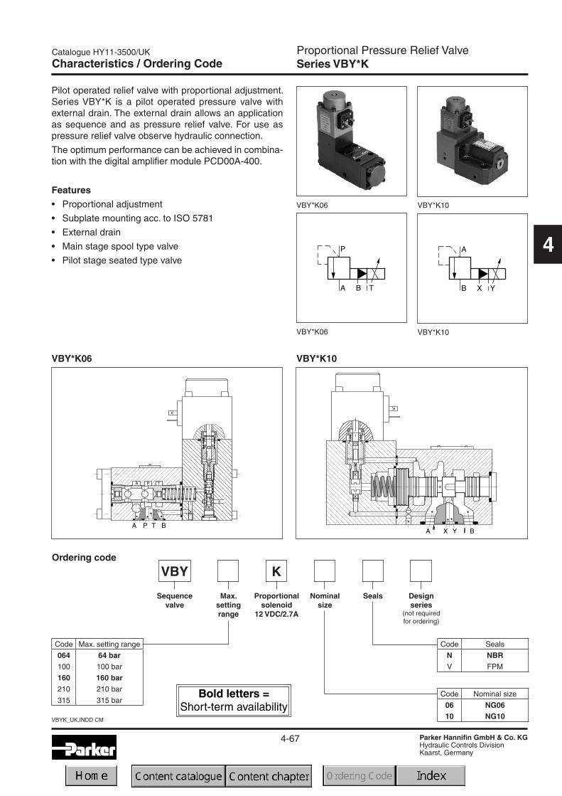
Proportional Pressure Relief ValveSeries VBY*K
4
VBY*K10
Features• Proportional adjustment
• Subplate mounting acc. to ISO 5781
• External drain
• Main stage spool type valve
• Pilot stage seated type valve
Pilot operated relief valve with proportional adjustment.Series VBY*K is a pilot operated pressure valve withexternal drain. The external drain allows an applicationas sequence and as pressure relief valve. For use aspressure relief valve observe hydraulic connection.
The optimum performance can be achieved in combina-tion with the digital amplifier module PCD00A-400.
Ordering code
Characteristics / Ordering Code
VBY*K06
VBY*K10VBY*K06
VBY*K10VBY*K06
Nominalsize
VBY
Sequencevalve
Max.settingrange
Proportionalsolenoid
12 VDC/2.7A
Seals
Code Seals
N NBRV FPM
Code Max. setting range
064 64 bar100 100 bar
160 160 bar210 210 bar
315 315 barCode Nominal size
06 NG0610 NG10
K
Designseries
(not requiredfor ordering)

4-68
VBYK_UK.INDD CM
Catalogue HY11-3500/UK
Parker Hannifin GmbH & Co. KGHydraulic Controls DivisionKaarst, Germany
Proportional Pressure Relief ValveSeries VBY*K
4
Technical data
GeneralDesign Proportional pressure valve
Nominal size NG06 NG10Interface Subplate mounting according to ISO 5781
Actuation Proportional solenoid
Mounting position unrestricted
Ambient temperature [°C] -20 ... +70
Weight [kg] 5
HydraulicsMax. operating pressure [bar] Ports P and A 315; Port T depressurized Ports A and B 315; Port Y depressurized
Nominal flow [l/min] 40 160
Adjustment range [bar] up to 64, 100, 160, 210, 315
Fluid Hydraulic oil as per DIN 51 524 ... 525
Viscosity recommended [cSt] /maximum [cSt] /
[mm²/s][mm²/s]
30 ... 5020 ... 380
Pressure medium temperaturerecommendedmaximum
[°C][°C]
30 ... 50-20 ... +70
Permitted contamination ISO 4406 (1999); 18/16/13
Linearity [%] ±3.5 at > 15% pnom.
Repeatability [%] <±2
Hysteresis [%] ±1.5 to pmax
Response time [ms] <150 <200
Manufacturing tolerance [%] ±5 to pmax
ElectricalDuty ratio [%] 100 ED
Protection class IP65 at EN 60529 (plugged and mounted)
Nominal voltage [VDC] 12
Max. current [A] 2.7
Ambient temperature [°C] -20...+70
Coil resistance [Ohm] 21 at 20°C
Solenoid connection Connector as per EN 175301-803
Power amplifier PCD00A-400
Characteristic pressure curves for NG06 p = f (Uset)
Setting range max. 64 bar Setting range max. 210 bar
Technical Data / Characteristic Curves Characteristic Cur

4-69
Catalogue HY11-3500/UK
Parker Hannifin GmbH & Co. KGHydraulic Controls DivisionKaarst, Germany
VBYK_UK.INDD CM
Proportional Pressure Relief ValveSeries VBY*K
4
Setting range max. 315 bar
Setting range max. 64 bar
p/Q characteristicsmeasured at t = 50°C and ν = 35 mm²/s
Setting range max. 210 barSetting range max. 160 bar
Setting range max. 100 bar
Characteristic Curves
NG06

4-70
VBYK_UK.INDD CM
Catalogue HY11-3500/UK
Parker Hannifin GmbH & Co. KGHydraulic Controls DivisionKaarst, Germany
Proportional Pressure Relief ValveSeries VBY*K
4
Characteristic Curves
Step response signal
Setting range max. 210 bar
Setting range max. 64 bar
p/Q characteristicsmeasured at t = 50°C and ν = 35 mm²/s
Setting range max. 100 bar
Setting range max. 160 bar Setting range max. 210 bar
NG10
NG06

4-71
Catalogue HY11-3500/UK
Parker Hannifin GmbH & Co. KGHydraulic Controls DivisionKaarst, Germany
VBYK_UK.INDD CM
Proportional Pressure Relief ValveSeries VBY*K
4
Dimensions
NG06
Mounting pattern ISO 5781-03-04-0-00
The connectionB must be lockedonto the subplatefor standard ap-plications.
Surface finish Bolt kit - DIN 912 12.9NBR FPM
BK-M5x30-4pcs7.6 Nm±15%
SK-VMY-L06-N SK-VMY-L06-V

4-72
VBYK_UK.INDD CM
Catalogue HY11-3500/UK
Parker Hannifin GmbH & Co. KGHydraulic Controls DivisionKaarst, Germany
Proportional Pressure Relief ValveSeries VBY*K
4
Dimensions
NG10
Mounting pattern ISO 5781-06-07-0-00
Surface finish Bolt kit - DIN 912 12.9FPM
BK-M10x50-4pcs63 Nm±15%
SK-VB/VM-A10V

Unloading ValvesSeries UR / US (Parker), R4U (Denison)
4-73
Catalogue HY11-3500/UK
Parker Hannifin GmbH & Co. KGHydraulic Controls DivisionKaarst, Germany
UR-US-R4U_UK.INDD CM
4
Characteristics
Subplate mounted unloading valves are available withboth Parker (series UR/US) and Denison (series R4U)model codes.
These valves are used to unload a circuit at low pressure.The mechanically adjustable pressure signal to unloadthe main stage has to be applied to port X.The pressuredifferential between opening and closing is nominal 15or 28 % of the setting pressure.
28 % for pressure stages bar 70, 175
15 % for pressure stages bar 250, 350
Typical applications are unloading of pumps in an ac-cumulator circuit or unloading of the low pressure stageof a double pump.
In addition, the US series is vented by electrical operation.
Features• Pilot operated unloading valve
• Interface- subplate mounting to ISO 5781
• 4 pressure stages
• 2 switching types (series US)
• 3 adjustment modes- hand knob- acorn nut with lead seal- DIN lock
UR25MR4U06
UR US
US25MR4U06 with vent function

4-74
UR-US-R4U_UK.INDD CM
Catalogue HY11-3500/UK
Parker Hannifin GmbH & Co. KGHydraulic Controls DivisionKaarst, Germany
Unloading ValvesSeries UR (Parker) Ordering Code
4
Ordering Code
Code Pressure stages
07 up to 70 bar
17 up to 175 bar
25 up to 250 bar
35 up to 350 bar
Code Nominal size
10 NG10
25 NG25
32 NG32
Adjust-ment
Unloadingvalve
Nominalsize
Pilot oil
S
Poppetspring
Seals
Interface Designseries
(not requiredfor ordering)
Pressurestages
Code Seals
N NBR
V FPM
Code Adjustment
SHand knob(Standard)
L DIN lock
AAcorn nut with
lead seal
Pilot oil
Code Pilot Drain
1 Internal External
4 Internal Internal
Code Interface
MSubplatemountingISO 5781
UR
The Parker model code shouldbe used for all new applications.Otherwise also refer to Denisonmodel code.
4-75
Catalogue HY11-3500/UK
Parker Hannifin GmbH & Co. KGHydraulic Controls DivisionKaarst, Germany
UR-US-R4U_UK.INDD CM
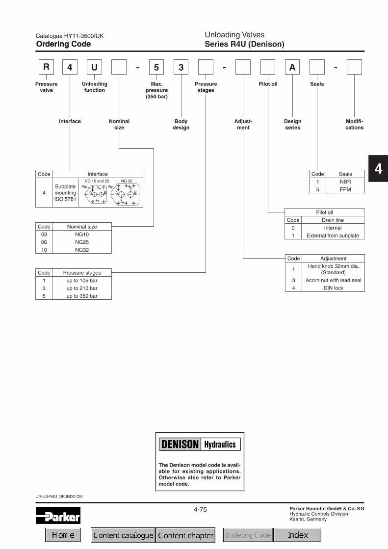
Ordering CodeUnloading ValvesSeries R4U (Denison)
4
Code Pressure stages
1 up to 105 bar
3 up to 210 bar
5 up to 350 bar
Ordering Code
Bodydesign
R
Pressurevalve
U 5
Pilot oil
Designseries
34
Seals
Interface Modifi-cations
Max.pressure(350 bar)
Code Interface
4SubplatemountingISO 5781
Adjust-ment
Code Seals
1 NBR
5 FPM
Unloadingfunction
Nominalsize
Pressurestages
Code Nominal size
03 NG10
06 NG25
10 NG32
- -
Code Adjustment
1Hand knob 32mm dia.
(Standard)
3 Acorn nut with lead seal
4 DIN lock
-
Pilot oil
Code Drain line
0 Internal
1 External from subplate
A
The Denison model code is avail-able for existing applications.Otherwise also refer to Parkermodel code.

4-76
UR-US-R4U_UK.INDD CM
Catalogue HY11-3500/UK
Parker Hannifin GmbH & Co. KGHydraulic Controls DivisionKaarst, Germany
Unloading ValvesSeries US (Parker)
4Code Nominal size
10 NG10
25 NG25
32 NG32
US
Switchingtype
Solenoid
S W
Adjust-ment
Unloadingvalve with
elec.unloading
Nominalsize
Interface
Pressurestages
Pilot
Poppetspring
Seals Options
Withoutplug
Designseries
(not requiredfor ordering)
Ordering Code Ordering Code
Code Interface
MSubplatemountingISO 5781
Code Pressure stages
07 up to 70 bar
17 up to 175 bar
25 up to 250 bar
35 up to 350 bar
Code Switching type
1Solenoid not activ.unpress. circulation
9Solenoid activatedunpress. circulation
Code Solenoid
KJUGPN
12V =24V =98V =205V =
115V/50 Hz230V/50 Hz
Pilot oil
Code Pilot Drain
1 Internal External
4 Internal Internal
Code Seals
N NBR
V FPM
Code Options
omit Standard
S with slow unloading
Code Adjustment
SHand knob(Standard)
L DIN lock
AAcorn nut with
lead seal
The Parker model code shouldbe used for all new applications.Otherwise also refer to Denisonmodel code.

4-77
Catalogue HY11-3500/UK
Parker Hannifin GmbH & Co. KGHydraulic Controls DivisionKaarst, Germany
UR-US-R4U_UK.INDD CM
Unloading ValvesSeries R4U with Vent Function (Denison)
4
Ordering Code
Pilot oil
Ventvalve
function
Pressurevalve
Interface Nominalsize
Pressurestages
Adjust-ment
Designseries
Solenoidvoltage
A
SealsRelieffunction
Modifi-cations
5-
Pilot oil
Code Drain line
0 internal
1 external from subplate
Code Vent valve
09 1) Solenoid not activ.unpress. circulation
11 2) Solenoid activatedunpress. circulation
1) Solenoid de-energized: open to tankSolenoid energized: vent line blocked
2) Solenoid de-energized: vent line blockedSolenoid energized: open to tank
Code Seals
1 NBR
5 FPM
Code Adjustment
1 Hand knob (Standard)
3 Acorn nut with lead seal
4 DIN lock
----
Code Nominal size
03 NG10
06 NG25
10 NG32
Code Pressure stages
1 up to 105 bar
3 up to 210 bar
5 up to 350 bar
-
Code Interface
4SubplatemountingISO 5781
R U4
Unloadingfunction
3
Bodydesign
Code Voltage
G0RG0QGARGAGW06W07
12V =24V =98V =205V =
115V / 50 Hz230V / 50 Hz
The Denison model code is avail-able for existing applications.Otherwise also refer to Parkermodel code.

4-78
UR-US-R4U_UK.INDD CM
Catalogue HY11-3500/UK
Parker Hannifin GmbH & Co. KGHydraulic Controls DivisionKaarst, Germany
Unloading ValvesSeries UR / US (Parker), R4U (Denison)
4
GeneralNominal size 10 25 32Interface Subplate mounting acc. ISO 5781
Mounting position as desired, horizontal mounting prefered
Ambient temperature [°C] -20...+80
Weight [kg] 4.4 6.2 7.7
HydraulicMax. operating pressure [bar] Ports A and X 350, Ports B and Y depressurized
Pressure stages [bar] 75, 175, 250, 350
Pressure differential 28 % (for pressure stages 75 bar and 175 bar); 15% (for pressure stages 250 bar and 350 bar)
Nominal flow [l/min] 150 350 650
Fluid Hydraulic oil according to DIN 51524 ... 525
Viscosity,recommended [cSt] /permitted [cSt] /
[mm²/s][mm²/s]
30 ... 5020...380
Fluid temperature [°C] -20 ... +70
Filtration ISO 4406 (1999); 18/16/13
Electrical (solenoid)Duty ratio [%] 100 ED; CAUTION: coil temperature up to 180 °C possible
Max. switching frequency 160000 (DC), 7200 (AC)
Protection class IP65 in according with EN 60529 (plugged and mounted)
Code Denison / Code Parker] Code
Supply voltage
Tolerance supply voltage
Power consumption hold
in rush
[V]
[%]
[W]
[W]
Solenoid connection Connector as per EN 175301-803
Wiring min. [mm2] 3 x 1.5 recommended
Wiring length max. [m] 50 recommended
Technical Data
GeneralNominal size 10 25 32Interface Subplate mounting acc. ISO 5781
Mounting position as desired, horizontal mounting prefered
Ambient temperature [°C] -20...+80
Weight [kg] 2.7 4.5 6.0
HydraulicMax. operating pressure [bar] Ports A and X 350, Ports B and Y depressurized
Pressure stages [bar] 75, 175, 250, 350
Pressure differential 28 % (for pressure stages 75 bar and 175 bar); 15% (for pressure stages 250 bar and 350 bar)
Nominal flow [l/min] 150 350 650
Fluid Hydraulic oil according to DIN 51524 ... 525
Viscosity,recommended [cSt] /permitted [cSt] /
[mm²/s][mm²/s]
30 ... 5020...380
[mm²/s] 20 ... 380
Fluid temperature [°C] -20 ... +70
Filtration ISO 4406 (1999); 18/16/13
UR / R4U
US / R4U with vent function
G0R / K G0Q / J GAR / U GAG / G W06 / P W07 / N
12V = 24V = 98V = 205V = 150 at 50Hz 230 at 50Hz
+5...-10 +5...-10 +5...-10 +5...-10 +5...-10 +5...-10
31 31 31 31 78 78
31 31 31 31 264 264

4-79
Catalogue HY11-3500/UK
Parker Hannifin GmbH & Co. KGHydraulic Controls DivisionKaarst, Germany
UR-US-R4U_UK.INDD CM
Unloading ValvesSeries UR / US (Parker), R4U (Denison)
4
Characteristic Curves
p/Q performance curveUR/US 1) Minimum pressure curve
1) The performance curves are measured with external drain.For internal drain the tank pressure has to be added to curve.
4-80
UR-US-R4U_UK.INDD CM
Catalogue HY11-3500/UK
Parker Hannifin GmbH & Co. KGHydraulic Controls DivisionKaarst, Germany
Unloading ValvesSeries UR / US (Parker), R4U (Denison)
4
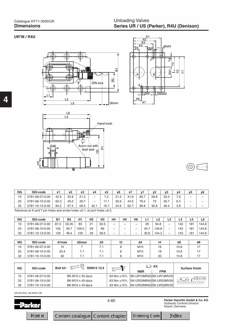
UR*M / R4U
NG ISO-code x1 x2 x3 x4 x5 x6 x7 y1 y2 y3 y4 y5 y610 5781-06-07-0-00 42.9 35.8 21.5 – 7.2 21.5 31.8 66.7 58.8 33.4 7.9 – –
25 5781-08-10-0-00 60.3 49.2 39.7 – 11.1 20.6 44.5 79.4 73 39.7 6.4 – –
32 5781-10-13-0-00 84.2 67.5 59.5 42.1 16.7 24.6 62.7 96.8 92.8 48.4 3.8 – –
Tolerance at X and Y pin holes and screw holes ±0.1, at port holes ±0.2.
NG ISO-code B1 B2 H1 H2 H3 H4 H5 H6 L1 L2 L3 L4 L5 L610 5781-06-07-0-00 87.3 33.35 83 21 62.5 – – – 29 94.8 – 143 181 144.8
25 5781-08-10-0-00 105 39.7 109.5 29 89 – – – 34.7 126.8 – 143 181 144.8
32 5781-10-13-0-00 120 48.4 120 29 99.5 – – – 30.6 144.3 – 143 181 144.8
NG ISO-code d1max d2max d3 t3 d4 t4 d5 d610 5781-06-07-0-00 15 7 7.1 8 M10 16 10.8 17
25 5781-08-10-0-00 23.4 7.1 7.1 8 M10 18 10.8 17
32 5781-10-13-0-00 32 7.1 7.1 8 M10 20 10.8 17
Dimensions
NG ISO-code Bolt kit - DIN912 12.9 Surface finishNBR FPM
10 5781-06-07-0-00 BK-M10 x 35-4pcs 63 Nm ±15% SK-UR10MN50 SK-UR10MV50
25 5781-08-10-0-00 BK-M10 x 45-4pcs 63 Nm ±15% SK-UR25MN50 SK-UR25MV50
32 5781-10-13-0-00 BK-M10 x 45-6pcs 63 Nm ±15% SK-UR32MN50 SK-UR32MV50

4-81
Catalogue HY11-3500/UK
Parker Hannifin GmbH & Co. KGHydraulic Controls DivisionKaarst, Germany
UR-US-R4U_UK.INDD CM
Unloading ValvesSeries UR / US (Parker), R4U (Denison)
4
US*M / R4Uwith vent function
NG ISO-code x1 x2 x3 x4 x5 x6 x7 y1 y2 y3 y4 y5 y610 5781-06-07-0-00 42.9 35.8 21.5 – 7.2 21.5 31.8 66.7 58.8 33.4 7.9 – –
25 5781-08-10-0-00 60.3 49.2 39.7 – 11.1 20.6 44.5 79.4 73 39.7 6.4 – –
32 5781-10-13-0-00 84.2 67.5 59.5 42.1 16.7 24.6 62.7 96.8 92.8 48.4 3.8 – –
Tolerance at X and Y pin holes and screw holes ±0.1, at port holes ±0.2.
NG ISO-code B1 B2 B3 H1 H2 H3 H4 H5 H6 L1 L2 L3 L4 L5 L610 5781-06-07-0-00 87.3 33.35 70 130 21 68.5 109.5 – – 29 94.8 – 143 181 165.6
25 5781-08-10-0-00 105 39.7 70 156.5 29 95 136 – – 34.7 126.8 – 143 181 165.6
32 5781-10-13-0-00 120 48.4 70 167 29 105.5 146.5 – – 30.6 144.3 – 143 181 165.6
NG ISO-code d1max d2max d3 t3 d4 t4 d5 d610 5781-06-07-0-00 15 7 7.1 8 M10 16 10.8 17
25 5781-08-10-0-00 23.4 7.1 7.1 8 M10 18 10.8 17
32 5781-10-13-0-00 32 7.1 7.1 8 M10 20 10.8 17
Dimensions
NG ISO-code Bolt kit - DIN912 12.9 Surface finishNBR FPM
10 5781-06-07-0-00 BK-M10 x 35-4pcs 63 Nm ±15% SK-RS10RN50 SK-RS10RV50
25 5781-08-10-0-00 BK-M10 x 45-4pcs 63 Nm ±15% SK-RS25RN50 SK-RS25RV50
32 5781-10-13-0-00 BK-M10 x 45-6pcs 63 Nm ±15% SK-RS32RN50 SK-RS32RV50

4-82
UR-US-R4U_UK.INDD CM
Catalogue HY11-3500/UK
Parker Hannifin GmbH & Co. KGHydraulic Controls DivisionKaarst, Germany
4
Notes

Pilot Operated Sequence ValvesSeries S (Parker), R4S (Denison)
4-83
Catalogue HY11-3500/UK
Parker Hannifin GmbH & Co. KGHydraulic Controls DivisionKaarst, Germany
S-R4S_UK.INDD CM
4
Characteristics / Technical Data
Subplate mounted sequence valves are available withboth Parker (series S) and Denison (series R4S) modelcodes.
These valves enable a hydraulic system to operate in apressure sequence. When the system pressure reachesthe setting pressure the valve opens and permits flow tothe secondary sub-system.
Features• Pilot operated sequence valve
• Subplate mounting acc. to ISO 5781
• 4 pressure stages
• 3 adjustment modes
- hand knob
- acorn nut with lead seal
- DIN knob
Technical data S/R4S
GeneralNominal size 10 25 32Interface Subplate mounting acc. ISO 5781
Mounting position as desired, horizontal mounting prefered
Ambient temperature [°C] -20...+80
Weight Series S/R4S [kg] 2.7 4.5 6.0
HydraulicMax. operating pressure [bar] Ports A, B and X 350, port Y depressurized
Pressure stages [bar] 75, 175, 250, 350 (series S), 105, 210, 350 (series R45)
Nominal flow [l/min] 150 350 650
Fluid Hydraulic oil according to DIN 51524 ... 525
Viscosity, recommended [cSt] /permitted [cSt] /
[mm²/s][mm²/s]
30 ... 5020 ... 380
Fluid temperature [°C] -20 ... +70
Filtration ISO 4406 (1999); 18/16/13

Pilot Operated Sequence ValvesSeries S (Parker), R4S (Denison)
4-84
S-R4S_UK.INDD CM
Catalogue HY11-3500/UK
Parker Hannifin GmbH & Co. KGHydraulic Controls DivisionKaarst, Germany
4
Ordering Code
Typical pressure c
P1 = setting pressureP2 = operating pressure
US
Adjust-ment
Sequencevalve
Nominalsize
Interface Pressurestages
Externaldrain fromsubplate
Poppetspring
Seals Designseries
(not requiredfor ordering)
M
Code Interface
MSubplatemountingISO 5781
Code Pressure stages
07 up to 70 bar
17 up to 175 bar
25 up to 250 bar
35 up to 350 bar
Code Seals
N NBR
V FPM
Code Nominal size
10 NG10
25 NG25
32 NG32
Code Adjustment
SHand knob(Standard)
L DIN lock
AAcorn nut with
lead seal
Code Pressure stages
1 up to 105 bar
3 up to 210 bar
5 up to 350 bar
R
Plaincap
Pressurevalve
S 5
Externaldrainfrom
subplate
Designseries
SealsInterface
4
Max.pressure(350 bar)
Code Interface
4SubplatemountingISO 5781
Adjust-ment
Code Seals
1 NBR
5 FPM
Relieffunction
Nominalsize
Pressurestages
– –
Code Nominal size
03 NG10
06 NG25
10 NG32
Code Adjustment
1Hand knob 32mm dia.
(Standard)
3 Acorn nut with lead seal
4Adjusting device
with key lock
3
Parker
Denison
1
1 A
The Denison model code is avail-able for existing applications.Otherwise also refer to Parkermodel code.
The Parker model code shouldbe used for all new applications.Otherwise also refer to Denisonmodel code.

Pilot Operated Sequence ValvesSeries S (Parker), R4S (Denison)
4-85
Catalogue HY11-3500/UK
Parker Hannifin GmbH & Co. KGHydraulic Controls DivisionKaarst, Germany
S-R4S_UK.INDD CM
4
Typical pressure characteristics at closing point
P1 = setting pressureP2 = operating pressure
Characteristics Curve
Time and pressure underlap depend on the characteristics of the specific system.
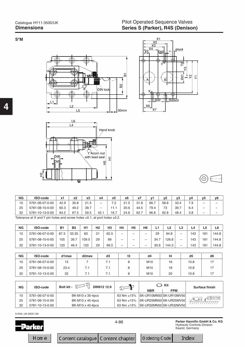
Pilot Operated Sequence ValvesSeries S (Parker), R4S (Denison)
4-86
S-R4S_UK.INDD CM
Catalogue HY11-3500/UK
Parker Hannifin GmbH & Co. KGHydraulic Controls DivisionKaarst, Germany
4
Dimensions
S*M
NG ISO-code x1 x2 x3 x4 x5 x6 x7 y1 y2 y3 y4 y5 y610 5781-06-07-0-00 42.9 35.8 21.5 – 7.2 21.5 31.8 66.7 58.8 33.4 7.9 – –
25 5781-08-10-0-00 60.3 49.2 39.7 – 11.1 20.6 44.5 79.4 73 39.7 6.4 – –
32 5781-10-13-0-00 84.2 67.5 59.5 42.1 16.7 24.6 62.7 96.8 92.8 48.4 3.8 – –
Tolerance at X and Y pin holes and screw holes ±0.1, at port holes ±0.2.
NG ISO-code B1 B2 H1 H2 H3 H4 H5 H6 L1 L2 L3 L4 L5 L6
10 5781-06-07-0-00 87.3 33.35 83 21 62.5 – – – 29 94.8 – 143 181 144.8
25 5781-08-10-0-00 105 39.7 109.5 29 89 – – – 34.7 126.8 – 143 181 144.8
32 5781-10-13-0-00 120 48.4 120 29 99.5 – – – 30.6 144.3 – 143 181 144.8
NG ISO-code d1max d2max d3 t3 d4 t4 d5 d6
10 5781-06-07-0-00 15 7 7.1 8 M10 16 10.8 17
25 5781-08-10-0-00 23.4 7.1 7.1 8 M10 18 10.8 17
32 5781-10-13-0-00 32 7.1 7.1 8 M10 20 10.8 17
NG ISO-code Bolt kit - DIN912 12.9 Surface finishNBR FPM
10 5781-06-07-0-00 BK-M10 x 35-4pcs 63 Nm ±15% SK-UR10MN50 SK-UR10MV50
25 5781-08-10-0-00 BK-M10 x 45-4pcs 63 Nm ±15% SK-UR25MN50 SK-UR25MV50
32 5781-10-13-0-00 BK-M10 x 45-6pcs 63 Nm ±15% SK-UR32MN50 SK-UR32MV50

Direct Operated Pressure Reducing ValveSeries VM
4-87
Catalogue HY11-3500/UK
Parker Hannifin GmbH & Co. KGHydraulic Controls DivisionKaarst, Germany
VM_UK.INDD CM
4
NG06 NG10
Characteristics
NG06
Features• Spool type valve
• Subplate mounting acc. to ISO 5781
• 4 pressure stages at NG06
• 3 pressure stages at NG10
• 2 adjustment modes
Direct operated pressure reducing valve with manual ad-justment. Series VM is a direct-controlled, spring loaded3 way pressure reducing valve, that is open in neutralposition. The valve closes the connection from P to A(NG06) or B to A (NG10) when the pre-set pressure isexceeded.
If the pressure increases due to an external influence inconnection A, the spool moves and opens the connec-tion from A to T (NG06) or A toY (NG10) until the pre-setpressure is reached.
NG10
NG06 NG10

Direct Operated Pressure Reducing ValveSeries VM
4-88
VM_UK.INDD CM
Catalogue HY11-3500/UK
Parker Hannifin GmbH & Co. KGHydraulic Controls DivisionKaarst, Germany
4
Ordering Code / Technical Data
Technical data
GeneralDesign Pressure reducing valve, direct operated, spool type
Nominal size NG 06 (CETOP 03 / NFPA D03) NG 10 (CETOP 05 / NFPA D05)Interface Subplate mounting according to ISO 5781
Mounting position unrestricted
Ambient temperature [°C] -20...+80
Weight [kg] 1.3 3.7
HydraulicsMax. operating pressure [bar] Port P and A 350
Port T depressurizedPort A and B 210
Port Y depressurized
Pressure stages [bar] 25; 64; 160; 210; 350 64; 125; 210
Nominal flow [l/min] 25 60
Fluid Hydraulic oil according to DIN 51524...525
Fluid temperature [°C] -20...+70
Viscosity recommended [cSt] /permitted [cSt] /
[mm²/s][mm²/s]
30...5020...380
Filtration ISO 4406 (1999); 18/16/13
Ordering code NG06Setting pressure max.
Pressurestages
Adjustmentscrew
withhexagonsocket
Nominalsize
FPMSeals
Designseries
(not requiredfor ordering)
VM
LockGaugeport
VA
Pressurereliefvalve
Code Pressure stages
025 1) up to 25 bar
064 up to 64 bar125 2) up to 125 bar160 1) up to 160 bar210 up to 210 bar
350 1) up to 350 bar
Code Lock
omit NormalZ DIN lock
1) only NG 062) only NG 10
Code Nominal size
06 NG 0610 NG 10
Code Gauge port
G 1) G 1/4”M 2) M18x1.5
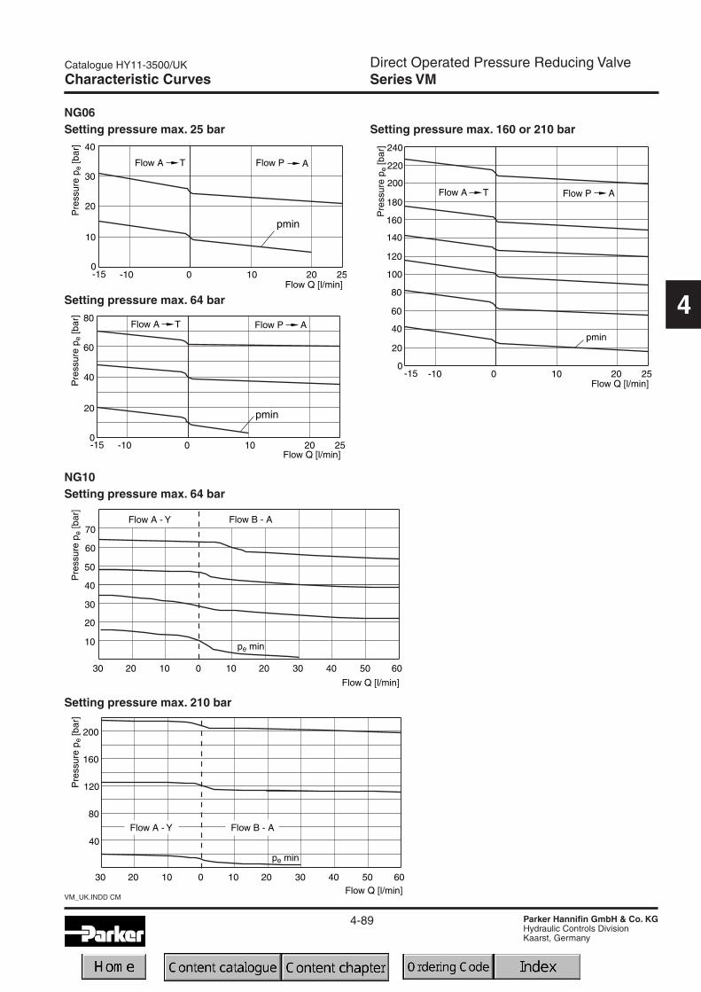
Direct Operated Pressure Reducing ValveSeries VM
4-89
Catalogue HY11-3500/UK
Parker Hannifin GmbH & Co. KGHydraulic Controls DivisionKaarst, Germany
VM_UK.INDD CM
4
Characteristic Curves
NG06Setting pressure max. 25 bar
Setting pressure max. 64 bar
Setting pressure max. 160 or 210 bar
NG10Setting pressure max. 64 bar
Setting pressure max. 210 bar

Direct Operated Pressure Reducing ValveSeries VM
4-90
VM_UK.INDD CM
Catalogue HY11-3500/UK
Parker Hannifin GmbH & Co. KGHydraulic Controls DivisionKaarst, Germany
4
Dimensions
NG06
Mounting pattern ISO 5781-03-04-0-00
Surface finishBolt kit DIN 912 12.9 FPM
BK-M5x30-4pcs7.6 Nm±15%
SK-VB/VM/VS-A06V

Direct Operated Pressure Reducing ValveSeries VM
4-91
Catalogue HY11-3500/UK
Parker Hannifin GmbH & Co. KGHydraulic Controls DivisionKaarst, Germany
VM_UK.INDD CM
4
Dimensions
NG10
Mounting pattern ISO 5781-06-07-0-00
Surface finishBolt kit DIN 912 12.9 FPM
BK-M10x50-4pcs63 Nm±15%
SK-VB/VM-A10V

4-92
VM_UK.INDD CM
Catalogue HY11-3500/UK
Parker Hannifin GmbH & Co. KGHydraulic Controls DivisionKaarst, Germany
4
Notes

Pilot Operated Pressure Reducing ValvesSeries PR (Parker), R4R (Denison)
4-93
Catalogue HY11-3500/UK
Parker Hannifin GmbH & Co. KGHydraulic Controls DivisionKaarst, Germany
PR-R4R_UK.INDD CM
4
Characteristics / Technical Data
Subplate mounted pressure reducing valves are availablewith both Parker (series PR) and Denison (series R4R)model codes.
These valves are used to control the pressure in the sec-ondary part of the hydraulic system. Independent of theprimary pressure the secondary pressure is reduced tothe pressure setting. In order to avoid undesired motionthe valves are normally closed.
Features• Pilot operated with manual adjustment
• Subplate mounting acc. to ISO 5781
• Normally closed to avoid unintended motion
• 4 pressure stages
• 3 adjustment modes
- hand knob
- acorn nut with lead seal
- DIN lock
GeneralNominal size 10 25 32Interface Subplate mounting acc. ISO 5781
Mounting position as desired, horizontal mounting prefered
Ambient temperature [°C] -20...+80
Weight [kg] 4.8 7.2 13.5
HydraulicMax. operating pressure [bar] Ports A, B and X 350, port Y depressurized
Pressure stages [bar] 105, 175, 250, 350 (series PR), 105, 210, 350 (series R4R)
Nominal flow [l/min] 150 350 650
Fluid Hydraulic oil according to DIN 51524 ... 525
Viscosity, recommended [cSt] /permitted [cSt] /
[mm²/s][mm²/s]
30 ... 5020 ... 380
Fluid temperature [°C] -20 ... +70
Filtration ISO 4406 (1999); 18/16/13
Technical data
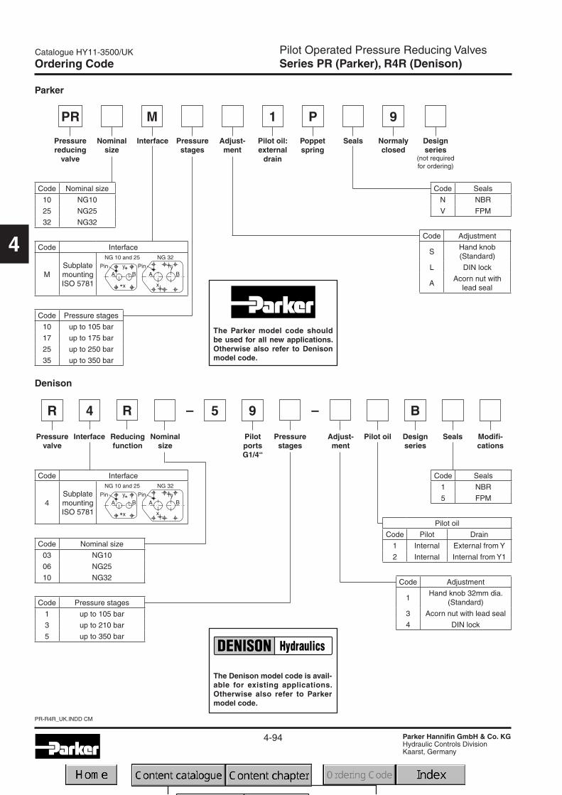
Pilot Operated Pressure Reducing ValvesSeries PR (Parker), R4R (Denison)
4-94
PR-R4R_UK.INDD CM
Catalogue HY11-3500/UK
Parker Hannifin GmbH & Co. KGHydraulic Controls DivisionKaarst, Germany
4
Ordering Code
PR M P
Adjust-ment
Pressurereducing
valve
Nominalsize
Interface Pressurestages
Pilot oil:external
drain
Poppetspring
Seals Designseries
(not requiredfor ordering)
Code Interface
MSubplatemountingISO 5781
Code Pressure stages
10 up to 105 bar
17 up to 175 bar
25 up to 250 bar
35 up to 350 bar
Code Seals
N NBR
V FPM
Code Nominal size
10 NG10
25 NG25
32 NG32
Code Adjustment
SHand knob(Standard)
L DIN lock
AAcorn nut with
lead seal
R
PilotportsG1/4“
Pressurevalve
R 5
Pilot oil Designseries
Seals
91
Interface
4
Adjust-ment
Reducingfunction
Nominalsize
Pressurestages
– –9
Parker
Denison
Normalyclosed
B
Modifi-cations
Code Pressure stages
1 up to 105 bar
3 up to 210 bar
5 up to 350 bar
Code Interface
4SubplatemountingISO 5781
Code Seals
1 NBR
5 FPM
Code Nominal size
03 NG10
06 NG25
10 NG32 Code Adjustment
1Hand knob 32mm dia.
(Standard)
3 Acorn nut with lead seal
4 DIN lock
Pilot oil
Code Pilot Drain
1 Internal External from Y
2 Internal Internal from Y1
The Denison model code is avail-able for existing applications.Otherwise also refer to Parkermodel code.
The Parker model code shouldbe used for all new applications.Otherwise also refer to Denisonmodel code.

Pilot Operated Pressure Reducing ValvesSeries PR (Parker), R4R (Denison)
4-95
Catalogue HY11-3500/UK
Parker Hannifin GmbH & Co. KGHydraulic Controls DivisionKaarst, Germany
PR-R4R_UK.INDD CM
4
Characteristic Curves
Reduced pressure pA versus flow QPR10M 1)
Reduced pressure pA versus flow QPR25M 1)
Reduced pressure pA versus flow QPR32M 1)
Minimum pressure curve
1) Measured at 350 bar primary pressure pB.
Minimum pressure curve
Minimum pressure curve

Pilot Operated Pressure Reducing ValvesSeries PR (Parker), R4R (Denison)
4-96
PR-R4R_UK.INDD CM
Catalogue HY11-3500/UK
Parker Hannifin GmbH & Co. KGHydraulic Controls DivisionKaarst, Germany
4
Dimensions
PR*M
NG ISO-code x1 x2 x3 x4 x5 x6 x7 y1 y2 y3 y4 y5 y610 5781-06-07-0-00 42.9 35.8 21.5 – 7.2 – 31.8 66.7 – 33.4 7.9 – –
25 5781-08-10-0-00 60.3 49.2 39.7 – 11.1 – 44.5 79.4 – 39.7 6.4 – –
32 5781-10-13-0-00 84.2 67.5 59.5 42.1 16.7 – 62.7 96.8 – 48.4 3.8 – –
Tolerance for all dimensions ±0.2
NG ISO-code B1 B2 H1 H2 H3 H4 H5 H6 L1 L2 L3 L4 L5 L6 L710 5781-06-07-0-00 87.3 33.35 83 21 62.5 – – – 29 94.8 60.8 143 181 144.8 38.6
25 5781-08-10-0-00 105 39.7 109.5 29 89 – – – 34.7 126.8 60.8 143 181 144.8 38.6
32 5781-10-13-0-00 120 48.4 120 29 99.5 – – – 30.6 144.3 60.8 143 181 144.8 38.6
NG ISO-code d1max d2max d3 t3 d4 t4 d5 d610 5781-06-07-0-00 15 7 7.1 8 M10 16 10.8 17
25 5781-08-10-0-00 23.4 7.1 7.1 8 M10 18 10.8 17
32 5781-10-13-0-00 32 7.1 7.1 8 M10 20 10.8 17
X1: G 1/4“
Y1: G 1/4“
NG ISO-code Bolt kit - DIN912 12.9 Surface finishNBR FPM
10 5781-06-07-0-00 BK-M10 x 35-4pcs 63 Nm ±15% SK-PR10MN50 SK-PR10MV50
25 5781-08-10-0-00 BK-M10 x 45-4pcs 63 Nm ±15% SK-PR25MN50 SK-PR25MV50
32 5781-10-13-0-00 BK-M10 x 45-6pcs 63 Nm ±15% SK-PR32MN50 SK-PR32MV50

Pilot Operated Proportional Reducing ValveSeries VMY
4-97
Catalogue HY11-3500/UK
Parker Hannifin GmbH & Co. KGHydraulic Controls DivisionKaarst, Germany
VMY_UK.INDD CM
4
Characteristics / Ordering Code
Proportional pressure reducing valves of the series VMYallow the variable adjustment of the reduced pressurefrom 0 bar up to the nominal pressure.
The valve consists of a spool type main stage and aproportionally operated pilot stage.The desired pressurecan be variably set corresponding to the command signalspecified on the amplifier.The proportional solenoid con-verts the current of the amplifier into force on the valvepoppet of the pilot stage.
Typical applications are pressure systems, test equip-ment, or counterweight systems.
The optimum performance can be achieved in combina-tion with the digital amplifier module PCD00A-400 foropen loop systems or with PWDXXA-40* for closed loopsystems.
FunctionWith the proportional solenoids de-energized the mainspring forces the main spool into the neutral position.PortA is connected to port T.Thus the reduced pressure onlydepends on the back pressure in the external drain pipeand/or the tank pressure and can accordingly be reduceddown to 0 bar.The pressure present in the P line deliversthe pilot oil to the pilot stage via a flow control valve.
When the proportional solenoid is energized, the pilotpressure is increased in the pilot pressure area, and themain spool moves against the spring until the connectionP - A opens. The regulation of the reduced pressure onconnection A takes place by the constant comparison ofthe actual pressure and the reference pressure of thepilot stage.
1) connection on port Y2) pmin = 0 bar possible
Ordering code
Pressurestages
Proportionalsolenoid9V/2.5A
Nominalsize
NG06
Highpressurechannel
Designseries
(not requiredfor ordering)
Pilot
PKVMY
Reducingvalve
Code Pressure stages
064 up to 64 bar100 up to 100 bar160 up to 160 bar210 up to 210 bar315 up to 315 bar
06
FPMSeals
V
Pilot oil
Code Pilot Drain
N 1) Internal External 2)
T Internal Internal
Port B has to be blocked

Pilot Operated Proportional Reducing ValveSeries VMY
4-98
VMY_UK.INDD CM
Catalogue HY11-3500/UK
Parker Hannifin GmbH & Co. KGHydraulic Controls DivisionKaarst, Germany
4
Technical Data
GeneralDesign 3 way proportional reducing valve, pilot operated, spool design
Nominal size 06 (DIN NG06 / CETOP 03 / NFPA D03)
Interface Subplate mounting according to ISO 5781
Actuation Proportional solenoid
Mounting position unrestricted
Ambient temperature [°C] -20 ... +80
Weight [kg] 2.8
HydraulicsMax. operating pressure [bar] Ports P, A 315; Port T, Y depressurized; port B has to be blocked
Pressure stages [bar] 64, 100, 160, 210, 315
Nominal flow [l/min] 40
Fluid Hydraulic oil as per DIN 51 524 ... 535
Viscosity recommended [cSt] /permitted [cSt] /
[mm²/s][mm²/s]
30 ... 5020 ... 380
Fluid temperature [°C] -20 ... +70
Filtration ISO 4406 (1999); 18/16/13
Linearity [%] See characteristic pressure curves
Repeatability [%] <±2
Hysteresis [%] ±1.5 to pmax
Response time [ms] <150
ElectricalDuty ratio [%] 100 ED
Protection class IP65 in accordance with EN 60529 (plugged and mounted)
Nominal voltage [VDC] 9
Max. current [A] 2.7
Ambient temperature [°C] -20...+70
Coil resistance [Ohm] -2.1 (at 20°C)
Solenoid connection Connector as per EN 175301-803
Power amplifier, recommended PCD00A-400

Pilot Operated Proportional Reducing ValveSeries VMY
4-99
Catalogue HY11-3500/UK
Parker Hannifin GmbH & Co. KGHydraulic Controls DivisionKaarst, Germany
VMY_UK.INDD CM
4
Characteristic Curves
Characteristic pressure lines p = f (Uset)
Setting range max. 210 barSetting range max. 64 bar

Pilot Operated Proportional Reducing ValveSeries VMY
4-100
VMY_UK.INDD CM
Catalogue HY11-3500/UK
Parker Hannifin GmbH & Co. KGHydraulic Controls DivisionKaarst, Germany
4
Characteristic Curves
p/Q characteristicsmeasured at t = 50°C and ν 0 35 mm²/s
Setting range max. 64 bar
Setting range max. 100 bar
Setting range max. 160 bar
Setting range max. 210 bar

Pilot Operated Proportional Reducing ValveSeries VMY
4-101
Catalogue HY11-3500/UK
Parker Hannifin GmbH & Co. KGHydraulic Controls DivisionKaarst, Germany
VMY_UK.INDD CM
4
Characteristic Curves
Setting range max. 315 bar
p/Q characteristicsmeasured at t = 50°C and ν 0 35 mm²/s
Step responseTypical curve

Pilot Operated Proportional Reducing ValveSeries VMY
4-102
VMY_UK.INDD CM
Catalogue HY11-3500/UK
Parker Hannifin GmbH & Co. KGHydraulic Controls DivisionKaarst, Germany
4
Dimensions
Mounting pattern ISO 5781-03-04-0-00
The connectionB must be lockedonto the subplatefor standard ap-plications.
Surface finishBolt kit DIN 912 12.9 FPM
BK-M5x30-4pcs7.6 Nm±15%
SK-VMY-L06-V
Port Y: G1/4

Proportional Pressure Reducing ValvesSeries PE*W (Parker), R4R (Denison)
4-103
Catalogue HY11-3500/UK
Parker Hannifin GmbH & Co. KGHydraulic Controls DivisionKaarst, Germany
PEW-R4R_UK.INDD CM
4
Characteristics / Technical Data
Subplate mounted proportional pressure reducing valvesare available with both Parker (series PE*W) and Denison(series R4R) model codes.
These valves have a proportional solenoid operated pilotstage and a cartridge main stage.
The optimum performance can be achieved in combina-tion with the digital amplifier module PCD00A-400.
Features• Pilot operated with proportional solenoid
• Continuous adjustment by proportional solenoid
• Subplate mounting according to ISO 5781
• 4 pressure stages
• Mechanical maximum pressure adjustment
GeneralNominal size 10 25 32Interface Subplate mounting acc. ISO 5781
Mounting position as desired, horizontal mounting prefered
Ambient temperature [°C] -20...+80
Weight [kg] 2.7 4.5 6.0
HydraulicMax. operating pressure [bar] Ports A and X 350, ports B and Y depressurized
Pressure stages [bar] 105, 250, 350
Nominal flow [l/min] 150 350 650
Fluid Hydraulic oil according to DIN 51524 ... 525
Viscosity recommended [cSt] /permitted [cSt] /
[mm²/s][mm²/s]
30 ... 5020 ... 380
Fluid temperature [°C] -20 ... +70
Filtration ISO 4406 (1999); 18/16/13
ElectricalDuty ratio [%] 100 ED
Protection class IP65 in accordance with EN 60529 (plugged and mounted)
Nominal voltage [V] 12
Max. current [A] 2.3
Coil resistance [Ohm] 4 at 20°C
Solenoid connection Connector as per EN 175301-803
Power amplifier, recommended PCD00A-400
Technical data

Proportional Pressure Reducing ValvesSeries PE*W (Parker), R4R (Denison)
4-104
PEW-R4R_UK.INDD CM
Catalogue HY11-3500/UK
Parker Hannifin GmbH & Co. KGHydraulic Controls DivisionKaarst, Germany
4
The Denison model code is avail-able for existing applications.Otherwise also refer to Parkermodel code.
Parker
PE M P
Off-board
electronics
Proportionalpressurereducing
valve
Nominalsize
Interface Pressurestages
Pilot oil:external
drain
Poppetspring
Seals Designseries
(not requiredfor ordering)
Code Interface
MSubplatemountingISO 5781
Code Seals
N NBR
V FPM
Code Nominal size
10 NG10
25 NG25
32 NG32
Code Pressure stages
10 up to 105 bar
21 up to 210 bar
35 up to 350 bar
91
Normalyclosed
W K
Solenoid12V, 2.3A
Plugconnection
EN 175301-803
W
Ordering Code
5RR
PilotportsG1/4“
B9
Pressurevalve
Pilot oil
Designseries
Seals
Interface
4
Max.pressure350 bar Adjust-
ment
GORP2
Reducingfunction
Nominalsize
Pressurestages
– –
Denison
Modifi-cations
Code Pressure stages
1 up to 105 bar
3 up to 210 bar
5 up to 350 bar
Code Interface
4SubplatemountingISO 5781
Code Seals
1 NBR
5 FPM
Code Nominal size
03 NG10
06 NG25
10 NG32
Code Adjustment
1Hand knob 32mm dia.
(Standard)
3 Acorn nut with lead seal
Pilot oil
Code Pilot Drain
1 Internal External from Y
2 Internal External from Y1
–
Prop.operation
Solenoidvoltage
12V, 2.3A
The Parker model code shouldbe used for all new applications.Otherwise also refer to Denisonmodel code.
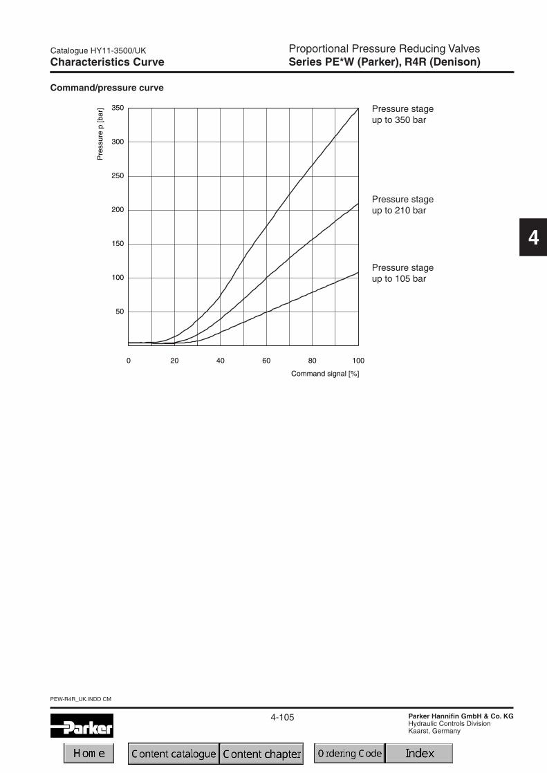
Proportional Pressure Reducing ValvesSeries PE*W (Parker), R4R (Denison)
4-105
Catalogue HY11-3500/UK
Parker Hannifin GmbH & Co. KGHydraulic Controls DivisionKaarst, Germany
PEW-R4R_UK.INDD CM
4
Characteristics Curve
Command/pressure curve
Pressure stageup to 350 bar
Pressure stageup to 210 bar
Pressure stageup to 105 bar

Proportional Pressure Reducing ValvesSeries PE*W (Parker), R4R (Denison)
4-106
PEW-R4R_UK.INDD CM
Catalogue HY11-3500/UK
Parker Hannifin GmbH & Co. KGHydraulic Controls DivisionKaarst, Germany
4
Characteristic Curves
Reduced pressure pA versus flow QPE10M*W / R4R03 1)
Reduced pressure pA versus flow QPE10M*W / R4R06 1)
Reduced pressure pA versus flow QPE10M*W / R4R10 1)
Minimum pressure curve
1) Measured at 350 bar primary pressure pB.
Minimum pressure curve
Minimum pressure curve
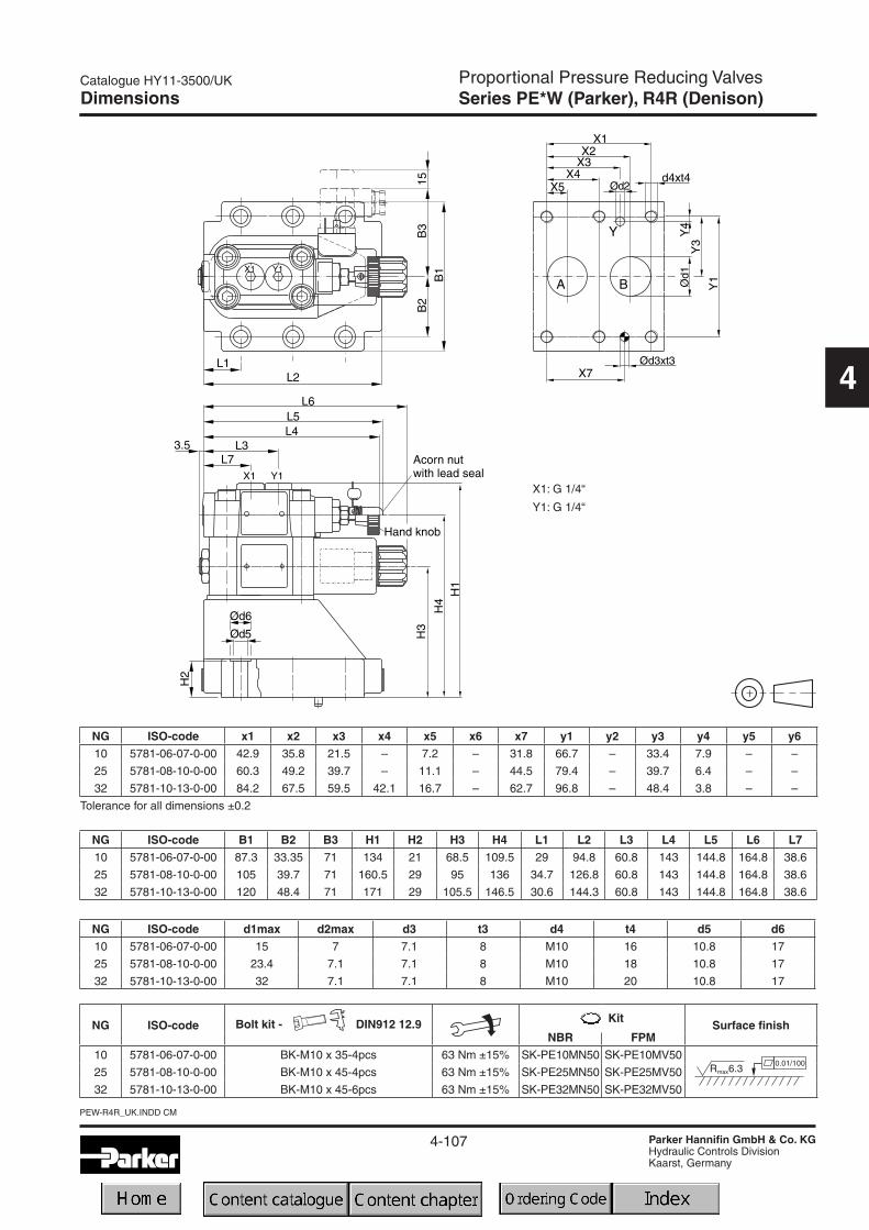
Proportional Pressure Reducing ValvesSeries PE*W (Parker), R4R (Denison)
4-107
Catalogue HY11-3500/UK
Parker Hannifin GmbH & Co. KGHydraulic Controls DivisionKaarst, Germany
PEW-R4R_UK.INDD CM
4
Dimensions
NG ISO-code x1 x2 x3 x4 x5 x6 x7 y1 y2 y3 y4 y5 y610 5781-06-07-0-00 42.9 35.8 21.5 – 7.2 – 31.8 66.7 – 33.4 7.9 – –
25 5781-08-10-0-00 60.3 49.2 39.7 – 11.1 – 44.5 79.4 – 39.7 6.4 – –
32 5781-10-13-0-00 84.2 67.5 59.5 42.1 16.7 – 62.7 96.8 – 48.4 3.8 – –
Tolerance for all dimensions ±0.2
NG ISO-code B1 B2 B3 H1 H2 H3 H4 L1 L2 L3 L4 L5 L6 L710 5781-06-07-0-00 87.3 33.35 71 134 21 68.5 109.5 29 94.8 60.8 143 144.8 164.8 38.6
25 5781-08-10-0-00 105 39.7 71 160.5 29 95 136 34.7 126.8 60.8 143 144.8 164.8 38.6
32 5781-10-13-0-00 120 48.4 71 171 29 105.5 146.5 30.6 144.3 60.8 143 144.8 164.8 38.6
NG ISO-code d1max d2max d3 t3 d4 t4 d5 d610 5781-06-07-0-00 15 7 7.1 8 M10 16 10.8 17
25 5781-08-10-0-00 23.4 7.1 7.1 8 M10 18 10.8 17
32 5781-10-13-0-00 32 7.1 7.1 8 M10 20 10.8 17
X1: G 1/4“
Y1: G 1/4“
NG ISO-code Bolt kit - DIN912 12.9 Surface finishNBR FPM
10 5781-06-07-0-00 BK-M10 x 35-4pcs 63 Nm ±15% SK-PE10MN50 SK-PE10MV50
25 5781-08-10-0-00 BK-M10 x 45-4pcs 63 Nm ±15% SK-PE25MN50 SK-PE25MV50
32 5781-10-13-0-00 BK-M10 x 45-6pcs 63 Nm ±15% SK-PE32MN50 SK-PE32MV50

4-108
PEW-R4R_UK.INDD CM
Catalogue HY11-3500/UK
Parker Hannifin GmbH & Co. KGHydraulic Controls DivisionKaarst, Germany
4
Notes

4-109
Catalogue HY11-3500/UK
Parker Hannifin GmbH & Co. KGHydraulic Controls DivisionKaarst, Germany
access04_UK.INDD CM
4
Pressure ValvesAccessories
DescriptionThreaded cable
jointBody colour
codingFigures
switchingOrder no.
Plug DIN 43650, design type AF, protection class IP 65Voltages up to 250 V
PG 9black, Bgrey, A
Fig. 150017105001711
PG11black, Bgrey, A
Fig. 15001716*5001717*
Plug with LED insert 24 V PG11black, Bgrey, A
Fig.1 andFig. 3
50015715001572
Plug with lamp insert 110 V PG11black, Bgrey, A
Fig.1 andFig. 4
50015735001574
Plug with lamp insert 220 V PG11black, Bgrey, A
Fig.1 andFig. 4
50015755001576
Plug with LED insert 24V and suppressing circuitry PG11black, Bgrey, A
Fig.1 andFig. 5
50017085001709
Plug with rectifier. Rectifier with 4 silicon diodes in bridgecircuit. Varistor in alternating current side to protect thediodes against power peaks
PG11black, Bgrey, A
Fig.1 andFig. 6
50017375001738
Plug with pull relief and translucent cover PG11black, Bgrey, A
Fig. 250017235001724
Application with bridge rectifier suitable for 5001723 and5001724
— —Fig. 2 and
Fig. 75001727
Application with bridge rectifier and lamp suitable for5001723 and 5001724
— —Fig. 2 and
Fig. 85001734
* If not ordered otherwise, valves with code P are supplied with these connectors.
Plugs

4-110
access04_UK.INDD CM
Catalogue HY11-3500/UK
Parker Hannifin GmbH & Co. KGHydraulic Controls DivisionKaarst, Germany
4
Central connector
Description Order No.
DIN 43563 6+PE 5004072
Pressure ValvesAccessoriesPlugs
![Catalogue HY11-2500/UK Chapter 4: Contents Pressure …cairohydraulic.com/products/1- Parker New/Parker Industrial... · Hydraulics Working pressure [bar] ... Catalogue HY11-2500/UK](https://img.pdfslide.net/doc/110x75/5af164717f8b9abc788e6097/catalogue-hy11-2500uk-chapter-4-contents-pressure-parker-newparker-industrialhydraulics.jpg)


![HY11 Results presentation.PPTX [Read-Only]€¦ · Financial results for the half year ended 31 December 2010 Product HY11 %Δ Factors Motor 1,262 4.7 Solid premium and net written](https://img.pdfslide.net/doc/110x75/600be3c6dcaba94db7324485/hy11-results-read-only-financial-results-for-the-half-year-ended-31-december-2010.jpg)