Embed Size (px)
Citation preview

Volume 4 • Issue 2 • 1000107J Adv Chem EngISSN: 2090-4568 ACE an open access journal
Review Article Open Access
Vaccaro and Malangone, J Adv Chem Eng 2014, 4:2 DOI: 10.4172/2090-4568.1000107
IntroductionThe general idea which supports the coupling between exothermic
and endothermic reactions relies on the possibility to make a system which is energetically self-sustaining; that is the exothermic reaction should provide the necessary heat to carry out the endothermic one. Such a coupling design is not straightforward to realize because several are the constraints to cope with; these include the limits imposed by the reaching of the equilibrium conditions at the prevailing temperature of the system, the proper adjusting of the inlet streams in order to, hopefully, correctly balance and synchronize the amounts of heat which are produced, transferred and absorbed inside the reactor and the attainment of working conditions able to avoid or reduce the onset of undesired side reactions. Furthermore, also the choice and the design of stable catalysts able to favour both endo- and exo-thermic reactions and the need to obtain high-purity or easy to separate products, which should be also not toxic and not dangerous for the environment, represent additional constraints.
The technique of taking advantage of the coupling of an exothermic source with an endothermic sink has, potentially, very broad applications and reactor configurations are reported in the literature to perform such a matching. According to the classification provided by Rahimpour et al. [1] direct, regenerative and recuperative coupling can be considered. In directly coupled systems the exothermic and endothermic reactions occur at the same time in the same vessel: in this case major concerns rely on the proper choice of the catalyst, which has to favour both the reactions, and on the purification of the outlet stream which includes products originated by both reactions. In the regenerative flow reactors (reported also as reverse-flow reactors) the exothermic and endothermic reactions take place in a single reactor but not at the same time: they occur alternatively in such a way that the latter occurs in a catalytic bed which has already been heated up by a previous exothermic step. The continuous switching between heating and cooling makes the temperature control of such a system complex and prone to the formation of hot spots, which may lead to a rapid decrease of the catalyst efficiency and to mechanical damages of the reactor walls [2]. To further complicate the system dynamics, washing operations may be needed in order to limit the presence of contaminants in the outlet streams. In recuperative coupling, the exothermic and endothermic reactions take place in adjacent chambers of the same reactor separated by conductive walls through which the heat is transferred from the energy-producing to the energy-consuming reaction. Due to its design, the recuperative heat exchange can operate both in counter-current and in co-current mode according to the relative direction of the flow of the reactant streams and offers several advantages with respect to the two previous configurations:
• The output streams from the endothermic and exothermicreactions are not mixed together;
• For the combustion reaction air can be used instead of oxygen,excluding, therefore the need to remove nitrogen from theproduct mixture;
• The choice of the operating parameters of the inlet streams,such as their flow rate, concentration and temperature and
the selection of reactant and catalyst types can be made independently for each stream.
This paper aims to provide a review of past and recent research activities performed to combine endothermic and exothermic reactions. Attention has been focused on the recuperative and direct coupling employed to process fuels in order to obtain hydrogen, especially for a distributed use as feed for small scale fuel cells systems. Moreover, information about reactors performance obtained in the two configurations is reported along with the methods used to remove CO and separate hydrogen or other high-value products through the use of membranes. In this context, techniques employed by researchers to study these reactors along with the role that modelling has in the development process are also described.
Recuperative Coupling ReactorsDesign
In this kind of reactor the exothermic and the endothermic reactions occur in adjacent chambers, separated by conductive walls. In this way heat produced in the exothermic channel may be directly transferred to the contiguous one where the endothermic reaction takes place.
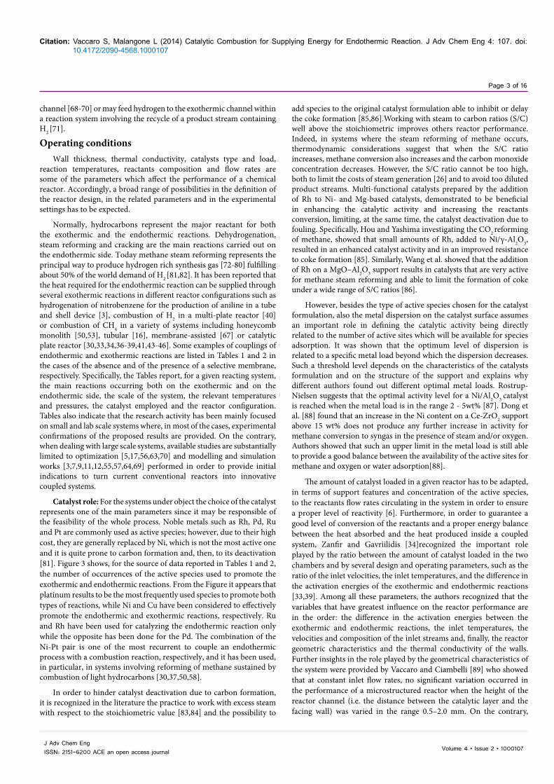
Recuperative coupling has been proposed in the literature both as a potential configuration to reduce the size and increase the productivity of existing conventional industrial reactors, and as a design strategy to develop small and very small scale systems aiming to work as portable devices to produce energy. It has been reported that the performance of some large scale reactors having a tube and shell heat exchanger [3-11] (Figure 1) or a concentric tubular configuration may be significantly increased by turning them into a recuperative configuration [12-17]. Here, the endothermic reaction generally occurs in the tube side and the exothermic reaction in the shell side, which, additionally, may include a multi-pass configuration for heat recovering and fuel pre-heating [15]. The catalyst inside this kind of devices can be supported on foam but it is, generally, arranged as fixed bed on both sides [16]. However, a fluidized bed configuration to reduce heat and mass transport limitations has been also considered [8-10,18]. The application of the recuperative configuration on small scale has led to the development of micro-reactors and micro-structured plate reactors. According to their name, they denote devices developed to pursue a process intensification strategy aiming at marked ly reducing the size of the reacting system achieving, at the same time, a given production objective [19].
*Corresponding author: Salvatore Vaccaro, Università degli Studi di Salerno, Via Ponte don Melillo, 84084 Fisciano (SA) Italy, Tel: +39-089-965-143; Fax: +39-089-964-057; E-mail: [email protected]
Received February 21, 2014; Accepted May 05, 2014; Published May 12, 2014
Citation: Vaccaro S, Malangone L (2014) Catalytic Combustion for SupplyingEnergy for Endothermic Reaction. J Adv Chem Eng 4: 107. doi: 10.4172/2090-4568.1000107
Copyright: © 2014 Vaccaro S, et al. This is an open-access article distributed under the terms of the Creative Commons Attribution License, which permits unrestricted use, distribution, and reproduction in any medium, provided the original author and source are credited.
Catalytic Combustion for Supplying Energy for Endothermic ReactionSalvatore Vaccaro* and Luca MalangoneUniversità degli Studi di Salerno, Via Giovanni Paolo II, 132, 84084 Fisciano (SA) Italy
Journal of Advanced Chemical EngineeringJo
urna
l of A
dvanced Chemical Engineering
ISSN: 2090-4568

Citation: Vaccaro S, Malangone L (2014) Catalytic Combustion for Supplying Energy for Endothermic Reaction. J Adv Chem Eng 4: 107. doi: 10.4172/2090-4568.1000107
Page 2 of 16
Volume 4 • Issue 2 • 1000107J Adv Chem EngISSN: 2151-6200 ACE an open access journal
Consequently, applied micro-technology gave the possibility to realize relatively low-weight portable devices able to combine several processes inside a single system [20-24].
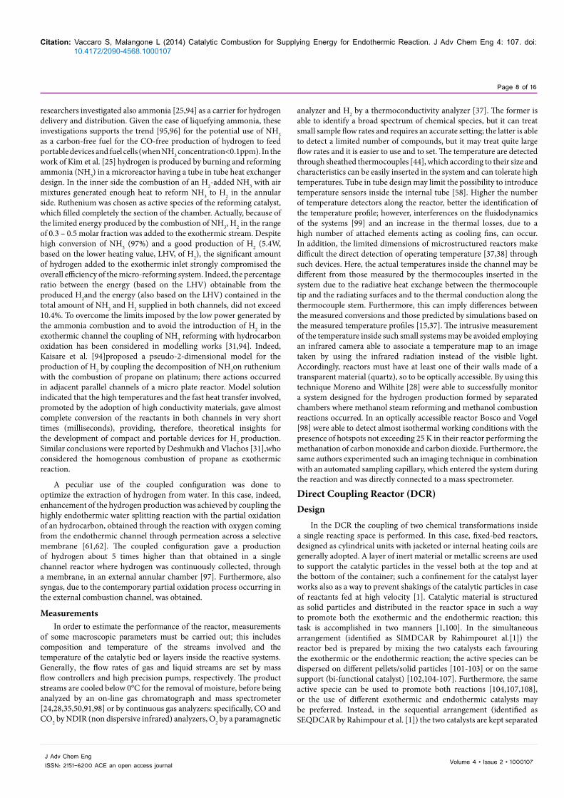
Literature references indicate that micro-reactors and micro-structured plate reactors differ substantially for the shape. The former are designed as cylindrical devices where heat produced by an inner combustor sustains the endothermic reaction occurring in a thin annular space surrounding it [25-27] or, may be constituted by the joining of several rectangular micro-channels arranged in such a way to form a network where the reforming channels are interspersed with the combustion ones [28,29]. The micro-structured plate reactor configuration (Figure 2) is, instead, generally formed by parallel thin plates delimiting chambers where exothermic and endothermic reactions occur simultaneously but separately in space [30-46]. Micro-structured reactors have, generally, inner dimension lower than one millimetre, and more specifically between ten and a hundred micrometers. Moreover, their design has to make possible the introduction/substitution of the catalytic materials and, in some cases, the insertion of a selective membrane, and must have, at the same time, low costs of manufacture. The main feature of these systems, in comparison with ordinary chemical reactors, is a much higher surface to volume ratio. This factor, along with the choice of materials with high thermal conductivity, allows for a high heat-exchange rate able to limit the formation of hot spots and to favour the dissipation of the heat produced in the exothermic channel. The catalysts for the heat absorbing reaction (for instance: reforming) and for the heat generating one (for instance: combustion) are, generally, wash coated [23,35,37,44,45] on the opposite faces of metallic slabs delimiting the chambers of the reactor. Therefore, the actual reactor space is the slab over which both mass and heat transfer and chemical reactions occur while the channel acts only as a duct. In many cases before of the coating treatment, the metallic slabs are properly processed [47-49] to favour the adhesion of the catalytic layer. In these systems, a multi-pass configuration for the pre-heating of the streams entering the reactor [44] along with a design able to enhance the control of the temperature inside the reforming chamber has been also employed. Specifically, Venkataraman et al. [44] adopted a reactor configuration where the endothermic channel is longer than the exothermic one: this is helpful in decreasing the downstream temperatures so to enhance the conversion of side reactions occurring in this channel (i.e., water gas shift reaction).
The micro-structured plate configuration can be easily scaled-up
just repeating, in space, the single unit shown in Figure 2; in this way the advantage of an invariant performance of the system with the capacity is obtained in front of a linear increase in the cost for the scaling-up [24,44,48]. Monolithic catalytic reactors [50-53] represent another possible configuration for such systems. They have a tubular jacketed design in which the catalyst is wash coated on a metallic honeycomb monolith, both in the tube and in the shell space. With respect to conventional fixed bed catalytic arrangements, they are characterized by a negligible pressure drop and by a very limited transport resistance inside the catalytic pore structure. However, high costs and complications for loading, packaging, sealing and unloading make their use quite limited [54]. A design enhancement in the recuperative coupling configuration is the inclusion of a selective membrane, which allows the increase of the yield of the desired products and/or enhances the conversion of a reactant even above the equilibrium value. A selective membrane gives the advantage to operate a continuous removal of one of the reaction products, shifting, at the same time, the equilibrium of the reaction towards its formation: i.e. this way of proceeding may be useful for obtaining a high-purity hydrogen stream from the endothermic side of a system and/or for removing carbon dioxide so to increase the conversion of CO in the water gas shift reaction. The membrane separates the channel containing the products stream from another channel (permeate side) in which the product of interest is collected. An auxiliary gas stream (sweep gas), generally N2 or Ar, flows in the permeate channel of the system to carry outside the recovered species. As the flow rate of the sweep gas is increased, the partial pressure of the product inside the permeate channel decreases; this leads to an increment in the driving force across the membrane and, therefore, to an enhancement in the species recovery. However, apart from the disadvantage to obtain an increasingly dilution of the product in the sweep gas stream, it is not useful to increase indefinitely the flow rate of the latter because beyond a certain value the permeation rate of H2 remains unchanged [55,56]. Alternative ways to increase the productivity may include: lowering the pressure in the permeate side below that of the reacting side [57,58] and/or removal of one of the secondary products from the products stream [59,60].
A typical single membrane-assisted configuration for hydrogen production consists of a concentric three tube reactor: in the inner tube the exothermic reaction occurs, the intermediate channel is employed for the endothermic reaction while the external channel is used for hydrogen recovery since the wall separating the intermediate and the external channel functions as an hydrogen selective membrane [18,55-57,61-67]. An alternative to this kind of arrangement considers the exothermic and the endothermic reactions in external and intermediate chambers, respectively, and hydrogen recovery from the inner tube [58]. A more complex configuration is employed for a double membrane-assisted reactor, which is a concentric four tube reactor: with respect to the previous one it includes also an internal additional tube that, across a membrane wall, may receive water permeating from the exothermic
Endothermic feed
Exothermic feed
Endothermic products
Exothermic products
Figure 1: Recuperative coupling configuration for a tube and shell reactor configuration. Adapted from [5].
Reforming Channel
Combustion Channel
Combustion Catalyst
Reforming Catalyst
Solid wall
Figure 2: Recuperative coupling configuration for a micro-structured plate reactor. Adapted from [30].
Citation: Vaccaro S, Malangone L (2014) Catalytic Combustion for Supplying Energy for Endothermic Reaction. J Adv Chem Eng 4: 107. doi: 10.4172/2090-4568.1000107
Page 3 of 16
Volume 4 • Issue 2 • 1000107J Adv Chem EngISSN: 2151-6200 ACE an open access journal
channel [68-70] or may feed hydrogen to the exothermic channel within a reaction system involving the recycle of a product stream containing H2 [71].
Operating conditionsWall thickness, thermal conductivity, catalysts type and load,
reaction temperatures, reactants composition and flow rates are some of the parameters which affect the performance of a chemical reactor. Accordingly, a broad range of possibilities in the definition of the reactor design, in the related parameters and in the experimental settings has to be expected.
Normally, hydrocarbons represent the major reactant for both the exothermic and the endothermic reactions. Dehydrogenation, steam reforming and cracking are the main reactions carried out on the endothermic side. Today methane steam reforming represents the principal way to produce hydrogen rich synthesis gas [72-80] fulfilling about 50% of the world demand of H2 [81,82]. It has been reported that the heat required for the endothermic reaction can be supplied through several exothermic reactions in different reactor configurations such as hydrogenation of nitrobenzene for the production of aniline in a tube and shell device [3], combustion of H2 in a multi-plate reactor [40] or combustion of CH4 in a variety of systems including honeycomb monolith [50,53], tubular [16], membrane-assisted [67] or catalytic plate reactor [30,33,34,36-39,41,43-46]. Some examples of couplings of endothermic and exothermic reactions are listed in Tables 1 and 2 in the cases of the absence and of the presence of a selective membrane, respectively. Specifically, the Tables report, for a given reacting system, the main reactions occurring both on the exothermic and on the endothermic side, the scale of the system, the relevant temperatures and pressures, the catalyst employed and the reactor configuration. Tables also indicate that the research activity has been mainly focused on small and lab scale systems where, in most of the cases, experimental confirmations of the proposed results are provided. On the contrary, when dealing with large scale systems, available studies are substantially limited to optimization [5,17,56,63,70] and modelling and simulation works [3,7,9,11,12,55,57,64,69] performed in order to provide initial indications to turn current conventional reactors into innovative coupled systems.
Catalyst role: For the systems under object the choice of the catalyst represents one of the main parameters since it may be responsible of the feasibility of the whole process. Noble metals such as Rh, Pd, Ru and Pt are commonly used as active species; however, due to their high cost, they are generally replaced by Ni, which is not the most active one and it is quite prone to carbon formation and, then, to its deactivation [81]. Figure 3 shows, for the source of data reported in Tables 1 and 2, the number of occurrences of the active species used to promote the exothermic and endothermic reactions. From the Figure it appears that platinum results to be the most frequently used species to promote both types of reactions, while Ni and Cu have been considered to effectively promote the endothermic and exothermic reactions, respectively. Ru and Rh have been used for catalyzing the endothermic reaction only while the opposite has been done for the Pd. The combination of the Ni-Pt pair is one of the most recurrent to couple an endothermic process with a combustion reaction, respectively, and it has been used, in particular, in systems involving reforming of methane sustained by combustion of light hydrocarbons [30,37,50,58].
In order to hinder catalyst deactivation due to carbon formation, it is recognized in the literature the practice to work with excess steam with respect to the stoichiometric value [83,84] and the possibility to
add species to the original catalyst formulation able to inhibit or delay the coke formation [85,86].Working with steam to carbon ratios (S/C) well above the stoichiometric improves others reactor performance. Indeed, in systems where the steam reforming of methane occurs, thermodynamic considerations suggest that when the S/C ratio increases, methane conversion also increases and the carbon monoxide concentration decreases. However, the S/C ratio cannot be too high, both to limit the costs of steam generation [26] and to avoid too diluted product streams. Multi-functional catalysts prepared by the addition of Rh to Ni- and Mg-based catalysts, demonstrated to be beneficial in enhancing the catalytic activity and increasing the reactants conversion, limiting, at the same time, the catalyst deactivation due to fouling. Specifically, Hou and Yashima investigating the CO2 reforming of methane, showed that small amounts of Rh, added to Ni/γ-Al2O3, resulted in an enhanced catalyst activity and in an improved resistance to coke formation [85]. Similarly, Wang et al. showed that the addition of Rh on a MgO–Al2O3 support results in catalysts that are very active for methane steam reforming and able to limit the formation of coke under a wide range of S/C ratios [86].
However, besides the type of active species chosen for the catalyst formulation, also the metal dispersion on the catalyst surface assumes an important role in defining the catalytic activity being directly related to the number of active sites which will be available for species adsorption. It was shown that the optimum level of dispersion is related to a specific metal load beyond which the dispersion decreases. Such a threshold level depends on the characteristics of the catalysts formulation and on the structure of the support and explains why different authors found out different optimal metal loads. Rostrup-Nielsen suggests that the optimal activity level for a Ni/Al2O3 catalyst is reached when the metal load is in the range 2 - 5wt% [87]. Dong et al. [88] found that an increase in the Ni content on a Ce-ZrO2 support above 15 wt% does not produce any further increase in activity for methane conversion to syngas in the presence of steam and/or oxygen. Authors showed that such an upper limit in the metal load is still able to provide a good balance between the availability of the active sites for methane and oxygen or water adsorption[88].
The amount of catalyst loaded in a given reactor has to be adapted, in terms of support features and concentration of the active species, to the reactants flow rates circulating in the system in order to ensure a proper level of reactivity [6]. Furthermore, in order to guarantee a good level of conversion of the reactants and a proper energy balance between the heat absorbed and the heat produced inside a coupled system, Zanfir and Gavriilidis [34]recognized the important role played by the ratio between the amount of catalyst loaded in the two chambers and by several design and operating parameters, such as the ratio of the inlet velocities, the inlet temperatures, and the difference in the activation energies of the exothermic and endothermic reactions [33,39]. Among all these parameters, the authors recognized that the variables that have greatest influence on the reactor performance are in the order: the difference in the activation energies between the exothermic and endothermic reactions, the inlet temperatures, the velocities and composition of the inlet streams and, finally, the reactor geometric characteristics and the thermal conductivity of the walls. Further insights in the role played by the geometrical characteristics of the system were provided by Vaccaro and Ciambelli [89] who showed that at constant inlet flow rates, no significant variation occurred in the performance of a microstructured reactor when the height of the reactor channel (i.e. the distance between the catalytic layer and the facing wall) was varied in the range 0.5–2.0 mm. On the contrary,

Citation: Vaccaro S, Malangone L (2014) Catalytic Combustion for Supplying Energy for Endothermic Reaction. J Adv Chem Eng 4: 107. doi: 10.4172/2090-4568.1000107
Page 4 of 16
Volume 4 • Issue 2 • 1000107J Adv Chem EngISSN: 2151-6200 ACE an open access journal
at constant inlet velocities higher channel height resulted in lower conversion and smoother temperature profile along the reactor.
Homogeneous vs. heterogeneous exothermic source: In some cases the catalytic combustion of a fuel is replaced by a homogeneous combustion. This substitution has the advantage to eliminate the deactivation and regeneration issues related to the catalyst use and to provide a heat source which is, potentially, more efficient than a heterogeneous process. By direct ignition, homogeneous combustion may reach, almost instantly, very high temperature without any pre-heating step, typical of the catalyzed processes; this, in a coupled reactor configuration, strongly reduces the time needed for the endothermic reaction to reach the desired conversion [31]. However, in this kind of systems difficulties in setting the position of the flame in a desired area
of the combustor may arise: this matter makes the thermal coupling with the endothermic channel quite complex and requires accurate adjustment of the inlet conditions of the fuel (i.e. flow rate and mixing) [25]. A further difficulty is the instability of a homogeneous confined flame when, for relatively small reactors, the surface to volume ratio is too high and leads to a strong cooling of the flame.
Actually, the effect of the molar flow rate of the exothermic inlet on the thermal behaviour of the reactor can be extended also to catalytic reactors, noting that variations in this parameter may affect the position and the formation of hot spots along the reactor length. In addition, in an heterogeneous coupled system also the inlet temperatures of the reactants need to be carefully set both to assure high reactor performance and to limit the reaching of too high temperatures inside
*T denotes the temperatures inside the reactive chamber or the inlet or wall value, where specifiedS and L stand for small and large, respectivelyExo and End stand for exothermic and endothermic, respectively
Table 1: Examples of recuperative coupling reactors.
No Type Reactions Scale T(K)* P Catalyst System Ref.
1
Exo Combustion of hydrogen:H2 + 0.5O2 →H2O
S
1073 (inlet) 13 atm Pt
Multi-plate reactor [40]Endo
Methane steam reforming:CH4 + H2O ↔ CO + 3H2CO + H2O ↔ CO2 + H2
- Ni/Al2O3
2
Exo Combustion of methane:CH4 +2O2 → CO2 +2H2O
S
986-1139 1 atm LaFe0.5Mg 0.5O3/Al2O3/ FeCrAl
Metallic monolith reactor [50]Endo
Reforming of methane with CO2:CH4 +CO2↔2CO + 2H2CO2 +H2↔ H2O + CO
1 atm Ni/SBA-15/ Al2O3/FeCrAl
3
Exo Combustion of methane:CH4 +2O2 → CO2 +2H2O
L
773-1073 - Ni
Ceramic monolith reactor [53]
Endo
Methane steam reforming:CH4 + H2O ↔ CO + 3H2CH4 + 2H2O ↔ CO2 + 4H2CO + H2O ↔ CO2 + H2
773-1073 - Ni
4Exo
Methane and hydrogen com-bustion:CH4 +2O2 → CO2 +2H2OH2 + 0.5O2→ H2O S
800 1 bar LaCoO3/La-γ- Al2O3/Ni-Cr
Tubular foam reactor [16]
Endo Methane steam reforming:CH4 + H2O ↔ CO + 3H2
374 -538 (inlet) 1 bar Ni
5
Exo Combustion of methane:CH4 +2O2 → CO2 +2H2O
S
820 (inlet) 1 atm Pt
Plate reactor [37]
Endo
Methane steam reforming:CH4 + H2O ↔ CO + 3H2CH4 + 2H2O ↔ CO2 + 4H2CO + H2O ↔ CO2 + H2
820 (inlet) 1 atm Ni
6Exo Combustion of methane:
CH4 +2O2 → CO2 +2H2O S803 (inlet) 1 bar -
Plate reactor [43]
Endo Methane steam reforming:CH4 + H2O ↔ CO + 3H2
803 (inlet) 1 bar -
7
Exo Combustion of methane:CH4 +2O2 → CO2 +2H2O
S
298 (inlet) 1.3 atm Pt
Plate reactor [44]Endo
Methane steam reforming:CH4 + H2O ↔ CO + 3H2CO + H2O ↔ CO2 + H2
873 (inlet) 1 atm Rh/ platinum-ceria
8Exo
Methane and hydrogen com-bustion:CH4 +2O2 → CO2 +2H2OH2 + 0.5O2 → H2O
S673-873 (inlet) 1.4 bar PdOx
Plate reactor [45]
Endo Methane steam reforming:CH4 + H2O ↔ CO + 3H2
673-873 (inlet) 1.4 bar Rh
9Exo Propane combustion:
C3H8 + AirS
298 (inlet) 1 atm Homogeneous, spark-ignited combustion
Micro-reactor [27]Endo Ammonia splitting:
2NH3 ↔ 3H2 + N2298 (inlet) 1 atm Ru

Citation: Vaccaro S, Malangone L (2014) Catalytic Combustion for Supplying Energy for Endothermic Reaction. J Adv Chem Eng 4: 107. doi: 10.4172/2090-4568.1000107
Page 5 of 16
Volume 4 • Issue 2 • 1000107J Adv Chem EngISSN: 2151-6200 ACE an open access journal
the reactor potentially able to cause catalyst deactivation by sintering [10].
Temperature control and autothermal behaviour: One of the main issues when coupling exothermic and endothermic reactions in such systems is the proper reaching of a desired level of temperature in order to promote the endothermic and exothermic reactions; this task can be better accomplished if some expedients to recover heat and to minimize thermal losses are applied. The pre-heating of the inlet stream by the hot exhaust stream is one of the most common technique adopted to purse this target; in this case the addition of multiple passes enables the preheating of the inlet combustion gases by the hot combustion exhausted stream [15]. Furthermore, the need to have different temperature levels inside the same chamber of a coupled system poses additional requests in term of optimization design. Outlet streams of endothermic channels in which steam reforming of hydrocarbons occur are characterized by the presence of carbon monoxide the amount
0
2
4
6
8
10
Pt Ni Cu Ru Pd Rh Others
Exothermic Endotermic
Figure 3: Number of occurrences of the active species considered in the coupled reactions reported in Tables 1 and 2. Others stand for: Mg, Co, Fe, Zn, Si, Ce, Re, Sn.
*T denotes the temperatures inside the reactive chamber or the inlet or wall value, where specifiedS and L stand for small and large, respectivelyExo and End stand for exothermic and endothermic, respectively
Table 2: Some examples of recuperative coupling with membrane.
No Type Reactions Scale T(K)* P Catalyst System Ref.
1Exo
Methanol synthesis: CO + 2H2 ↔ CH3OHCO2 + 3H2 ↔ CH3OH + H2OCO2 + H2 ↔ CO + H2O
L503 (inlet) 1 atm
76.98 bar
CuO/ZnO/ Al2O3(35% Copper, 15–50% Zinc,4–20% Aluminum).
Three-concentric tube reactor
[57][55]
End Cyclohexane dehydrogenation:C6H12 → C6H6 + 3H2
503 (inlet) 1 atm Pt/Al2O3
2Exo Ethane dehydrogenation:
C2H6 → C2H4 + H2 S- - -
Tube in tube reactor [62]End Water splitting:
H2O ↔ H2+0.5O2 973 -1073 2 atm -
3
Exo Combustion of methane: CH4 +2O2 → CO2 +2H2O
S
873 – 973 - Pt/ Al2O3
Three-concentric tube reactor [58]
End
Methane steam reforming: CH4 + H2O ↔ CO + 3H2CH4 + 2H2O ↔ CO2 + 4H2CO + H2O ↔ CO2 + H2
- 10 bar Ni/ Al2O3
4
Exo
Fischer–Tropsch synthesis:CO + 3H2 → CH4 + H2O2CO + 4H2 → C2H4 + 2 H2O2CO + 5H2 → C2H6 + 2 H2O3CO + 7H2 → C3H6 +2 H2O4CO + 9H2 → n-C4H10 + 4H2O4CO + 9H2 → i-C4H10 + 4H2O6.05CO + 12.23H2 →C 6.05 H 12:36 (C
5+ )+6.05H2OCO + H2O →CO2 + H2O
L
538(inlet) 1 bar
metalpart: 100Fe 21SiO2, acidicpart:SiO2 Al2O3 = 28 Three- and four concentric
tube reactor[70][64]
EndoDehydrogenation of decalin to naphthalene:Cis-Decalin / Trans-Decalin ↔ Tetralin+3H2 Tetralin ↔ Naphthalene + 5H2
614.28(inlet)
23 bar Pt-Sn/γ- Al2O3
5Exo
Methanol synthesis:CO + 2H2 ↔ CH3OHCO2 + 3H2 ↔ CH3OH + H2OCO2 + H2 ↔ CO + H2O
L500 76.98 bar CuO/ZnO/Al2O3 Three- and four concentric
tube reactor[63][69]
Endo Dehydrogenation of cyclohexane to benzene:C6H12→ C6H6 + H2
423–523 101.3 kPa Pt/ Al2O3
6Exo Dehydrogenation of methanol
2CH3OH→CH3OCH3 + H2O L500 76.98 bar CuO/ZnO/Al2O3 Three-concentric tube
reactor [56]
Endo Dehydrogenation of cyclohexane to benzene:C6H12→ C6H6 + H2
423–523 101.3 kPa Pt/ Al2O3
7Exo Partial oxidation of methane:
CH4 + 0.5O2 ↔ CO + 2H2 S- - -
Three-concentric tube reactor [61]
Endo Water splitting:H2O → 1/2O2 + H2
1073-1223 1 atm Ni/ Al2O3

Citation: Vaccaro S, Malangone L (2014) Catalytic Combustion for Supplying Energy for Endothermic Reaction. J Adv Chem Eng 4: 107. doi: 10.4172/2090-4568.1000107
Page 6 of 16
Volume 4 • Issue 2 • 1000107J Adv Chem EngISSN: 2151-6200 ACE an open access journal
of which is regulated by the competing reaction, which involves the conversion of CO to CO2 (water gas shift reaction). Unlike the steam reforming, the water gas shift reaction is favoured at lower temperature, meaning its conversion is always limited at the ordinary temperature the endothermic chamber works. The lengthening of just the terminal part of the endothermic channel allows to create a section, which is cooler than the previous part of the channel being thermally detached by the rest of the reactor, favouring, in this way, the water–gas shift reaction. This strategy was used by Venkataraman et al. [44] to increase the H2/CO ratio in an experimental reactor performing methane steam reforming on rhodium coupled with methane combustion on platinum: the downstream temperature in the reforming channel fell down to 200°C and the H2/CO ratio raised up to 42/1 with a S/C molar ratio of 4/1. A similar design improvement was proposed by Wanat et al. [35] in a lab-scale reactor in which the steam reforming of ethanol on rhodium was coupled with the methane combustion on platinum: in this way the
H2/CO ratio passed from 3/1 in the conventional reactor to 30/1 in the extended configuration.
In order to prevent excessive temperatures, further refinements in the reactor design may involve the use of an inert material in some section of the system in substitution of the catalytic bed. This way of proceeding gives the possibility to locally balance and control the equilibrium between the generated and consumed heat. However, how pointed out by some authors [14], the behaviour of a reactor may be different in steady state and transient mode (e.g. start-up conditions) when the maximum temperature value in the exothermic channel may be higher than that reached under steady state conditions: this makes the thermal control procedure complex, and the process feasible only if it complies with the operating conditions of both regimes.
The use of relatively high thermal conductivity materials (e.g. stainless steel) to build reactive systems may have positive and negative
No Type Reactions Scale T(K)* P Catalyst System Ref.
1
ExoCombustion of methane:CH4 +2O2 → CO2 +2H2OCH4 +0.5O2 → CO +2H2
S 1123(wall) 0.1 MPa
Pt/Al2O3
Pt-Ni/ Al2O3
SIMDCAR [104]
EndoReforming of methane with CO2:CH4 +CO2↔2CO + 2H2CO2 +H2↔ H2O + CO
2Exo Hydrogenation nitrobenzene to aniline
C6H5NO2 + 3H2→C6H5NH2 + 2H2O S 470-580 1 atm Cu/MgO SIMDCAR [105]Endo 1,4-butanediol to γ-butyroloctane dehydrogena-
tion: C4H10O2 → C4H6O2 + 2H2
3Exo Hydrogenation of benzene to cyclohexane:
C6H6 + 3H2 → C6H12 L 873 128.7 kPa FeNi SIMDCAR [103]
Endo Dehydrogenation of ethylbenzene to styrene:C6H5CH2 ↔ C6H5CHCH2 + H2
4Exo
Hydrogenation of maleic anhydride to tetrahydro-furan: C4H2O3 + 5H2 → C4H8O + 2H2O
S 493-553 1 MPa Cu-Zn-Ce SIMDCAR [106]
Endo Dehydrogenation of n-butanol to butylaldehyde:C4H9OH → C3H7CHO + H2
5Exo Gasoline combustion
S 1043 5 bar Ni SIMDCAR [108]Endo Gasoline reforming
6
Exo Methane oxidation:CH4 +2O2 → CO2 +2H2O
L 800and
640-665
2.9 and 2.5 atm
Pt/δ-Al2O3and
Ni/MgO-Al2O3
SIMDCAR and SEQDCAR [101]
Endo
Methane steam reforming and side reactions::CH4 + H2O ↔ CO + 3H2CH4 + 2H2O ↔ CO2 + 4H2CO + H2O ↔ CO2 + H2CH4 ↔ C + 2H2
7
ExoMethane and methanol oxidation:CH3OH +1.5O2 ↔ CO2 + 2H2OCH4 +2O2 → CO2 +2H2O S 590-720 -
Pt/Al2O3 and Ni/MgO
Pt0.2-Ni2.5/ Al2O3
SIMDCAR and SEQDCAR [102]
Endo
Methane and methanol steam reforming::CH3OH + H2O ↔ CO2 + 3H2CH4 + H2O ↔ CO + 3H2CO + H2O ↔ CO2 + H2
8Exo Hydrogenation of nitrobenzene to aniline:
C6H5NO2 + 3H2 ↔ C6H5NH2 + 2 H2O - 300-700 0.01-0.5 MPaPd/Al2O3
Fe2O3/γ-Al2O3,ZSM-5,Pt/AC
SIMDCAR [144][145]
Endo Dehydrogenation of ethylbenzene to styrene:C6H5C2H5 ↔ C6H5C2H3 + H2
9
Exo Oxidation of methanol to dimethoxymethane:3CH3OH + 0.5O2 → CH3OCH2OCH3 + 2H2O - 403-443 1 atm V2O5/TiO2
V2O5/TiO2–H2SO4SIMDCAR [107]
EndoCondensation of formaldehyde and methanol:HCHO + 2CH3OH → CH3OCH2OCH3 + H2OCH3OH + 0.5O2 → HCHO + H2O
*T denotes the temperatures inside the reactive chamber or the inlet or wall value, where specifiedS and L stand for small and large, respectivelyExo and End stand for exothermic and endothermic, respectively
Table 3: Some examples of direct coupling.

Citation: Vaccaro S, Malangone L (2014) Catalytic Combustion for Supplying Energy for Endothermic Reaction. J Adv Chem Eng 4: 107. doi: 10.4172/2090-4568.1000107
Page 7 of 16
Volume 4 • Issue 2 • 1000107J Adv Chem EngISSN: 2151-6200 ACE an open access journal
effects on the operation of high temperature reactors considering their relatively fast reaching of the thermal equilibrium [28]. On one hand, systems manufactured in this way operate almost under isothermal conditions, limiting, therefore, the formation of hot-spots [90,91]. On the other hand, the metallic high-conductive structure of these systems increases the heat losses. The higher the energy produced by the combustion side of the reactor, the higher the energy lost by dissipation to the surrounding. This consideration strongly limits the reactor potentialities and reduces the possibility for the system to reach autothermal conditions, i.e. able to sustain itself without the aid of external heat sources. In addition, extra heat has to be added to the whole energy balance of the system; in fact, just because the endothermic and exothermic reactions need to be carried out at high temperature so to favour high reaction rates and reactant conversions, the system is generally fed with already pre-heated streams. Yin et al.[50] experimentally verified the difficulty to operate under autothermal conditions considering the coupling of the methane combustion with the methane reforming with CO2. For such a system, although energy balances would allow the reforming of more than 3 moles of methane per mole of CH4 burned, the authors showed that the system was unable to accomplish a proper thermal coupling between the reactions without supplying external additional heat. Only working in combination with an electric heater operating at815°C, the whole performance of the reactor largely increased, reaching conversions of methane and CO2 in the reforming channel higher than 90% and with heat efficiency greater than 80%.The same authors in a previous work investigated the system performance through modelling: in that case the monolith reactor was able to realize the coupling between the exothermic and endothermic reactions by suitably adjusting the operating conditions [51].
An autothermal behaviour was accomplished in a membrane reformer for hydrogen generation operating with methane as reactant for combustion and steam reforming [58], and in a ceramic microchannel reactor performing the coupling of steam reforming and combustion of methanol [28]. In the first case the autothermal behaviour was accomplished by using an excess flow rate of exothermic stream with respect to the stoichiometric amount. Instead, in the second case the autothermicity was favoured by the use of a construction material with high insulating characteristics, which sensibly reduced the thermal dissipations.
The difficulty in evaluating the thermal losses is still a crucial problem and this topic is reported as one of the main issue to comply with since the first works dealing with recuperative reactors [53]. For instance, Frauhammer et al. [53], using a ceramic honeycomb monolith, in which methane was employed as reactant for the combustion and reforming, pointed out how the heat losses were significant, showing that the peak temperatures registered in the experiments were smaller compared to that predicted in the simplified simulations, which assumed the reactor as adiabatic. In order to face such issues, recommendations to reduce thermal losses, have been suggested. They include: reduction of the surface to volume ratio, use of high insulating materials [37,58], operation under vacuum [23,92] and use of low emissivity or high reflectance materials to reduce heat losses by radiation.
Co-current vs. counter-current flow: Relative co-current and counter-current flows [24] between the exothermic and the endothermic channel also affect the reactor behaviour. Simulations of counter-current operation showed that a potential lack of control of the heat produced by the combustion reaction [46,93] may exist due to the difficulty in matching the heat flux consumed and generated. In fact,
in this case, the ingress region of the combustion channel corresponds to the hottest area of the system due to the high rate of conversion resulting from the high reactant concentration. On the reforming side such an available heat cannot be fully utilized by the endothermic stream since it may absorb such a energy only before exiting, with the consequence that its residence time at high temperature becomes too short, so limiting the possibility to reach high conversions. The opposite occurs in correspondence of the exit of the combustion stream, where only the coolest part of the exothermic channel heats an entering endothermic stream having high concentrations. Thus, the design of a counter-current reactor may be more prone to the formation of hot and cold spots and alternative solutions are needed to balance the heat flux generated and consumed, especially if high outlet conversions are desired. These may include optimization of the relative position of the catalyst layers at endothermic and exothermic sides, optimization of catalyst distribution in the combustion channel, or optimization of fuel distribution along the reactor [93]. Reactants conversion changes according to the flow orientation being generally lower for the counter-current mode [38]. The higher conversions of co-current reactors with respect to the counter-current mode are consequence of the behaviours reported above that give rise to higher average temperatures and, then, to higher reaction rates [38,57].
Optimization technique: According to what reported in the previous paragraphs, it appears evident how complex may be to take into account all the parameters affecting the reactor performance. An optimization of the system that considers each of them is impracticable and, therefore, a preliminary screening analysis may be usefully applied. One of the currently applied techniques is the Differential Evolution (DE) method, which optimizes a problem by considering some constraints on the system parameters and calculates the solution that has the best score or fitness on the optimization problem at hand. Generally, when applying the DE method, the concentration of the desired species in the reactor outlet represents the objective function and the remaining parameters, such the maximum inlet temperatures, the pressure and the inlet molar flow rates, are varied within the applicable operative range of the system. In this context Khademi et al. [7] optimized the synthesis of methanol and benzene from cyclohexane dehydrogenation considering the methanol and benzene mole fractions as desired constraints and varying the inlet molar flow rate of the endothermic stream and the inlet temperatures of the exothermic and endothermic streams. Rahimpour et al. [17] maximized the yield of gasoline produced in a reactor in which the Fischer–Tropsch synthesis reactions and the endothermic dehydrogenation of cyclohexane to benzene took place: optimal value of the inlet molar flow rate and inlet temperatures of exothermic and endothermic streams and pressure of exothermic side were calculated.
The DE optimization strategy was successfully adopted also in membrane-assisted recuperative coupling reactors [56,63,66,68-71]. In particular, Rahimpour et al. proposed this technique to optimize the performance of a double membrane reactor: an water selective membrane was inserted to remove water from the exothermic side so to increase the productivity of gasoline synthesized from syngas and a Pd-Ag membrane was added to the endothermic side to separate H2 produced from dehydrogenation of decalin [17,68,70,71]. However, in order to scale up such a process to an industrial level, authors pointed out that some issues remain to be addressed such as the ageing of the catalysts and the difficulty to produce a cheap leak-free membrane.
Alternative to fossil fuels: As alternative to the use of conventional hydrocarbons and due mainly to its high hydrogen release capacity, some
Citation: Vaccaro S, Malangone L (2014) Catalytic Combustion for Supplying Energy for Endothermic Reaction. J Adv Chem Eng 4: 107. doi: 10.4172/2090-4568.1000107
Page 8 of 16
Volume 4 • Issue 2 • 1000107J Adv Chem EngISSN: 2151-6200 ACE an open access journal
researchers investigated also ammonia [25,94] as a carrier for hydrogen delivery and distribution. Given the ease of liquefying ammonia, these investigations supports the trend [95,96] for the potential use of NH3 as a carbon-free fuel for the CO-free production of hydrogen to feed portable devices and fuel cells (when NH3 concentration<0.1ppm). In the work of Kim et al. [25] hydrogen is produced by burning and reforming ammonia (NH3) in a microreactor having a tube in tube heat exchanger design. In the inner side the combustion of an H2-added NH3 with air mixtures generated enough heat to reform NH3 to H2 in the annular side. Ruthenium was chosen as active species of the reforming catalyst, which filled completely the section of the chamber. Actually, because of the limited energy produced by the combustion of NH3, H2 in the range of 0.3 – 0.5 molar fraction was added to the exothermic stream. Despite high conversion of NH3 (97%) and a good production of H2 (5.4W, based on the lower heating value, LHV, of H2), the significant amount of hydrogen added to the exothermic inlet strongly compromised the overall efficiency of the micro-reforming system. Indeed, the percentage ratio between the energy (based on the LHV) obtainable from the produced H2and the energy (also based on the LHV) contained in the total amount of NH3 and H2 supplied in both channels, did not exceed 10.4%. To overcome the limits imposed by the low power generated by the ammonia combustion and to avoid the introduction of H2 in the exothermic channel the coupling of NH3 reforming with hydrocarbon oxidation has been considered in modelling works [31,94]. Indeed, Kaisare et al. [94]proposed a pseudo-2-dimensional model for the production of H2 by coupling the decomposition of NH3on ruthenium with the combustion of propane on platinum; there actions occurred in adjacent parallel channels of a micro plate reactor. Model solution indicated that the high temperatures and the fast heat transfer involved, promoted by the adoption of high conductivity materials, gave almost complete conversion of the reactants in both channels in very short times (milliseconds), providing, therefore, theoretical insights for the development of compact and portable devices for H2 production.Similar conclusions were reported by Deshmukh and Vlachos [31],who considered the homogenous combustion of propane as exothermic reaction.
A peculiar use of the coupled configuration was done to optimize the extraction of hydrogen from water. In this case, indeed, enhancement of the hydrogen production was achieved by coupling the highly endothermic water splitting reaction with the partial oxidation of an hydrocarbon, obtained through the reaction with oxygen coming from the endothermic channel through permeation across a selective membrane [61,62]. The coupled configuration gave a production of hydrogen about 5 times higher than that obtained in a single channel reactor where hydrogen was continuously collected, through a membrane, in an external annular chamber [97]. Furthermore, also syngas, due to the contemporary partial oxidation process occurring in the external combustion channel, was obtained.
MeasurementsIn order to estimate the performance of the reactor, measurements
of some macroscopic parameters must be carried out; this includes composition and temperature of the streams involved and the temperature of the catalytic bed or layers inside the reactive systems. Generally, the flow rates of gas and liquid streams are set by mass flow controllers and high precision pumps, respectively. The product streams are cooled below 0°C for the removal of moisture, before being analyzed by an on-line gas chromatograph and mass spectrometer [24,28,35,50,91,98] or by continuous gas analyzers: specifically, CO and CO2 by NDIR (non dispersive infrared) analyzers, O2 by a paramagnetic
analyzer and H2 by a thermoconductivity analyzer [37]. The former is able to identify a broad spectrum of chemical species, but it can treat small sample flow rates and requires an accurate setting; the latter is able to detect a limited number of compounds, but it may treat quite large flow rates and it is easier to use and to set. The temperature are detected through sheathed thermocouples [44], which according to their size and characteristics can be easily inserted in the system and can tolerate high temperatures. Tube in tube design may limit the possibility to introduce temperature sensors inside the internal tube [58]. Higher the number of temperature detectors along the reactor, better the identification of the temperature profile; however, interferences on the fluidodynamics of the systems [99] and an increase in the thermal losses, due to a high number of attached elements acting as cooling fins, can occur. In addition, the limited dimensions of microstructured reactors make difficult the direct detection of operating temperature [37,38] through such devices. Here, the actual temperatures inside the channel may be different from those measured by the thermocouples inserted in the system due to the radiative heat exchange between the thermocouple tip and the radiating surfaces and to the thermal conduction along the thermocouple stem. Furthermore, this can imply differences between the measured conversions and those predicted by simulations based on the measured temperature profiles [15,37]. The intrusive measurement of the temperature inside such small systems may be avoided employing an infrared camera able to associate a temperature map to an image taken by using the infrared radiation instead of the visible light. Accordingly, reactors must have at least one of their walls made of a transparent material (quartz), so to be optically accessible. By using this technique Moreno and Wilhite [28] were able to successfully monitor a system designed for the hydrogen production formed by separated chambers where methanol steam reforming and methanol combustion reactions occurred. In an optically accessible reactor Bosco and Vogel [98] were able to detect almost isothermal working conditions with the presence of hotspots not exceeding 25 K in their reactor performing the methanation of carbon monoxide and carbon dioxide. Furthermore, the same authors experimented such an imaging technique in combination with an automated sampling capillary, which entered the system during the reaction and was directly connected to a mass spectrometer.
Direct Coupling Reactor (DCR)Design
In the DCR the coupling of two chemical transformations inside a single reacting space is performed. In this case, fixed-bed reactors, designed as cylindrical units with jacketed or internal heating coils are generally adopted. A layer of inert material or metallic screens are used to support the catalytic particles in the vessel both at the top and at the bottom of the container; such a confinement for the catalyst layer works also as a way to prevent shakings of the catalytic particles in case of reactants fed at high velocity [1]. Catalytic material is structured as solid particles and distributed in the reactor space in such a way to promote both the exothermic and the endothermic reaction; this task is accomplished in two manners [1,100]. In the simultaneous arrangement (identified as SIMDCAR by Rahimpouret al.[1]) the reactor bed is prepared by mixing the two catalysts each favouring the exothermic or the endothermic reaction; the active species can be dispersed on different pellets/solid particles [101-103] or on the same support (bi-functional catalyst) [102,104-107]. Furthermore, the same active specie can be used to promote both reactions [104,107,108], or the use of different exothermic and endothermic catalysts may be preferred. Instead, in the sequential arrangement (identified as SEQDCAR by Rahimpour et al. [1]) the two catalysts are kept separated

Citation: Vaccaro S, Malangone L (2014) Catalytic Combustion for Supplying Energy for Endothermic Reaction. J Adv Chem Eng 4: 107. doi: 10.4172/2090-4568.1000107
Page 9 of 16
Volume 4 • Issue 2 • 1000107J Adv Chem EngISSN: 2151-6200 ACE an open access journal
being disposed as alternating layers in the reactor vessel and then the endothermic and the exothermic reactions occur in a consecutive manner [101,102,109].
Operating conditions
Direct coupling reactors have been extensively studied. This type of reactor has several advantages such as operational simplicity [110], mitigation of thermodynamic limitations [111], reduction of the thermal losses due to the direct heat exchange between the endothermic and the exothermic processes [19], eco-friendly operations [112] and enhanced products selectivity [110,113]. Some examples of direct coupling configurations, along with the main operating conditions, are listed in Table 3. When the SIMDCAR configuration is adopted, the mixing of two different catalysts for the exo- and endo-thermic reactions is more frequent and more efficient [102] than the choice to have the same active specie to promote both reactions. Furthermore, some of the reactions occurring in this kind of device take the advantages of bi-functional catalysts [107,114]. There are, indeed, numerous cases where this choice revealed to be more efficient in terms of performance than systems operating with a mixture of two conventional catalysts [19].
As shown in Table 3, in analogy to the recuperative reactors, most of the papers deal with experimental works performed on small scale devices, while, large scale applications recur mainly in simulation activities carried out to analyze and propose potential performance improvements in existing plants via direct coupling. Most of the applications proposed in literature adopted a SIMDCAR approach. Therefore, the applications of the SEQDCAR configuration are less numerous [101,102,109] and one of them include the autothermal reformer (ATR) to produce hydrogen from the steam reforming of natural gas [109]. This situation may also derive from the comparison of the performance of the SIMDCAR and of SEQDCAR configurations applied at the same process from which it appears that the first is better than the second. For instance, Avci et al. [101] investigated, through a series of simulations, the effect of the two typical catalytic bed configurations on the performance of a directly coupled reactor performing combustion and steam reforming of methane for the production of hydrogen. When the two catalysts were mixed together to form a single catalytic bed, improved performance were accomplished with respect to that obtained with the configuration in which they were arranged as two consecutive layers; authors argued that this result was due to a more facilitated heat transport between the endothermic and exothermic reactions occurring with the first configuration.
The autothermal reforming of methane and methanol to hydrogen was studied in a similar way by Ma and Trimm [102]: the authors investigated the coupled oxidation and reforming reactions in a system where three different catalyst bed configurations were analyzed: a) two catalysts mixed in the same bed; b) two catalysts arranged as two consecutive different beds and c) two catalysts dispersed on the same support (bi-functional). Also in this case, the authors found that the best reactor performance was reached when the two catalysts were arranged as a single bed. Furthermore, even improved product yields were reached when a bi-functional catalyst was used. The mixed bed configuration makes the heat transfer between the exothermic and the endothermic reactions faster, achieving improvements in the conversion of methane and in the hydrogen selectivity (up to 65% and 85% respectively) [102].
SIMDCAR was proposed as a valid reactor configuration since the first industrial application dealing with methane steam reforming coupled with the production of ammonia [115] and with the production
of HCN from methane and ammonia coupled with the combustion of hydrogen produced in the endothermic reaction [2]. It was also used to couple the methane steam reforming with the catalytic oxidation of CH4 [101,102]. The SIMDCAR configuration was tested also with higher hydrocarbons with negative results. Specifically, Moon et al. [116] obtained unsatisfactoryselectivity to H2 and CO2 when investigated the autothermal reforming of isooctane. Furthermore, the risk connected with the use of higher hydrocarbons derives also from the possibility to have alkenes in the product stream: they may favour the deactivation of the catalyst in the downstream devices used for processing such outlet streams in order to remove carbon monoxide by water gas shift or oxidation reactions [117]. Such an issue was found by Ayabeet al. [118] who found ethylene in the products stream when performing the autothermal reforming of propane.
The main concern related to the use of complex fuels, such as gasoline or diesel is the elevated temperatures necessary to reach high conversions (>850°C) and the catalyst deactivation due to the coke formation especially when low cost Ni-based reforming catalysts are used. To avoid such issues, preliminary processes (pre-reforming) such as pyrolysis and cracking can be carried out [119]. Therefore, the fuel generally processed in the autothermal reactor consists of lighter hydrocarbons generated in these previous steps. Chen et al. [108] performed the ATR of gasoline with and without the pre-reforming steps under the same operating conditions: they found an almost complete conversion of gasoline associated with a very high selectivity to hydrogen in the first case, while the nickel-based catalyst resulted fouled with coke after a short time in the absence of the preliminary reforming steps.
Measurements
Dealing with cylindrical fixed bed reactor, the monitoring of the variable affecting the system performance may consist of temperature sensors and sampling probes equipped with valves mounted along the reactor length; this gives the possibility to detect the concentration and the temperature profiles when non-isothermal conditions are present [120]. Most of the systems analyzed refer to lab-scale reactors where the subsisting of plug flow conditions make thermal gradient in radial direction negligible. However, within actual fixed bed reactors undesired thermal radial gradients, which adversely affect the temperature control throughout the reactor, exist. In this case, the identification of the wall heat transfer coefficient is not trivial. It is commonly assumed that wall effects take place up to 1-1.5 particle diameters away from the wall and temperature readings through thermocouples in a region so close to the reactor wall could be affected by conductive error making the detected values unreliable [121]. The introduction of the reactants and the analysis of the product streams are performed in the same way of the recuperative reactors, i.e. mass flow controllers, precision pumps for liquid streams and on-line gas chromatographs connected to data acquisition systems. Because the concentration measurements are expensive and time consuming, due to the gas chromatography limits, only very few concentration measurements are generally performed in the most relevant positions.
Modelling
The description of the reactive systems proposed above evidences numerous ways and possibilities to realize a chemical reactor by varying the design, the geometrical configurations, the operating conditions and the type of catalyst. Despite such differences, the way in which these catalytic systems work can be re-conducted to general mechanisms involving the momentum, energy, and mass transport. Reactants flow

Citation: Vaccaro S, Malangone L (2014) Catalytic Combustion for Supplying Energy for Endothermic Reaction. J Adv Chem Eng 4: 107. doi: 10.4172/2090-4568.1000107
Page 10 of 16
Volume 4 • Issue 2 • 1000107J Adv Chem EngISSN: 2151-6200 ACE an open access journal
through the reactor chambers and come in contact with the catalytic material, generally arranged as porous structures; here the species, according to the operating conditions, adsorb and react forming the products that desorb and, then, leave the system. Generally, diffusion rather than convection regulates the mass transport inside the porous structure where catalytic heterogeneous reactions occur. However, depending on the temperatures involved, homogeneous reactions might also take place in the system. The temperature distribution along the reactor depends on many factors such as the heat released or absorbed by the chemical reactions, the heat and mass transport by convection and conduction in the fluid, theheat transport across the solid materials forming the reactor and the contributes due to the radiative heat exchanges. Considering also the unavoidable heat losses from the reactor walls, a temperature distribution along the reacting system will be established, which will affect in a complex way the behaviour of the whole reactive system [122].
Governing equations
The Navier-Stokes equations (1) in combination with the general principle of mass conservation (2) provide the resolution of the flow field inside a given system [123]. The Navier-Stokes equations form a system of three equations, for the x, y and z component, in four unknowns, i.e. pressure (p) and the three components of the velocity field v. Equation 2 is the fourth equation to solve the whole system.
[ ]τ∇ ∇ ∇∂
ρ ρ ρ∂
v =v + v × ×p -t
- + g (1)
∂∇
∂τñ + ×(ñv) = 0 (2)
In equation (1) τ is the stress tensor and g is the gravitational acceleration. Equation (1) is formally able to describe any flow condition (laminar and turbulent) in any geometric confinement. However, limits in the numerical resolution of the Navier-Stokes equations arise in turbulent conditions. In this case, in order to catch the strong time and spatial variations which characterize such a flow regime, a very detailed representation of the physical space where the process occurs has to be rendered by the inclusion of very numerous grid points. Currently, limited computational resources hinder the direct numerical resolution of the equation (1) under turbulent conditions and, therefore, additional model for the description of the turbulent contributes has been formulated. This means that a sort of filtering is imposed to the Navier-Stokes equations in order to be able to couple them with additional equations forming sub-models specifically tailored for the (simplified) resolution of only a part of the whole phenomenon. In particular, the k-ε model [124] adds, to the equations 1, two partial differential equations to model the turbulent kinetic energy, k, and the dissipation rate, ε; the Large Eddy Simulation model [125], instead, consider the direct application of the equations 1 for the numerical resolution on the large scales, and a turbulence model (e.g. k-ε model) for the resolution of the flow field at smaller scales.
The mixing of the chemical species (i) in the bulk phase due to convection and diffusion is described by the equation (3) [123]:
∂∇
∂ρ ∇ i
ii iY ) = -( JY( + v ×
t)+ r×
(3)
Where Yi is the mass fraction of the i species and ri is the related rate of production or of consumption due to the chemical reactions. Ji represents the diffusive mass flux of the species i which, for practical application, may be assumed to depend on concentration gradient only [36,123].
According to the domain where the fluid flows, meaning bulk or porous catalytic region, and considering that, generally, such processes
involve a multi-component mass transport, different approaches, more or less sophisticated, can be considered to express Ji . When assuming a Fick-like behaviour, valid under very diluted conditions (Yi<<1), each diffusive mass flux is not dependent on the flux of the other species and can be easily expressed in the bulk and in the porous domain by the equations (4) and (5), respectively:
ρ ∇ii iMDJ = - Y
where
j
iMi
ijj,j#i j
YY /
1DM ( M D )
−=
∑ (4)
ρ ∇Mieff,i iJ - D= Y where: 1/2
i,k porei
TD 48.5d ( )M
= (5)
M and Mj are the molecular weight of the mixture and of the species j, respectively, Dij is the binary diffusion coefficient, εp and τ are the porosity and tortuosity, respectively and T is the temperature. Diffusion processes within a pore involves two mechanisms: molecular and Knudsen diffusion. Molecular diffusion is dominant for large pore sizes and high system pressures while Knudsen diffusion becomes significant when the mean-free path of the molecular species is comparable with or larger than the pore size. The Knudsen diffusion coefficient is expressed as [126]:
1/2i,k pore
i
TD 48.5d ( )M
= (6)
When operating under undiluted conditions, more complex models should be employed. The Maxwell-Stefan model and the Dusty gas model describe the species transport in the gas and porous domain, respectively. They consider the diffusive flux of each species as dependent on that of the others, meaning that Ji cannot be expressed directly as a function of a concentration gradient. For their practical use, the most common form of the molar flux Ni (NiMi=Ji) according to the Maxwell-Stefan and the Dusty gas models is represented by the equations (7) and (8), respectively [127-129]:
Nj i
ji j ij
X X 1 PD RT≠
−= − ∇
∑ i jN N
(7)
j i 0i ii
i,K ij i,K
i,j i,
N
i
j i,K i,K
j
X X B PN XP X P 1D ,eff D eff RT RTì , D ,eff
where: D ,eff = D D ,ef Dô ô
; fε ε
≠
−= − ∇ − ∇ +
ρ=
+
ρ
∑ i jN N
(8)
Where X is the molar fraction, P is the pressure, Pj is the partial pressure of the j species, µis the viscosity, B0 is the permeability of the catalyst bed and R is the gas constant. N in the equation (7) is the diffusive molar flux, while N in the equation (8) includes also the convective contribute [4], which, therefore, has not to be added as additional term in the equation (3).In order to simplify the resolution of the differential equation system, arising by combining the equation (3) with the flux expressions given by relationships (7) and (8), only n-1 equations may be written since N
i i 1X =∑ [6].
The energy transport equation due to convection, conduction and mass diffusion can be expressed as[123]:
τρ
∂ ρ ∂ ∇ ∇ ∇
TC + v. =T q - [ :- vt
] + S
(9)
where Cρ is the specific heat, [ ]: vτ ∇ is the viscous dissipation term, S is the heat source due to the chemical reactions and q is the heat transport due to heat conduction and mass diffusion[122], i.e.:
λ∇ ∑ i iiq = - T + h J (10)
where, λ is the thermal conductivity of the mixture and hi is the specific enthalpy of species i. Balance equations are closed by relationships

Citation: Vaccaro S, Malangone L (2014) Catalytic Combustion for Supplying Energy for Endothermic Reaction. J Adv Chem Eng 4: 107. doi: 10.4172/2090-4568.1000107
Page 11 of 16
Volume 4 • Issue 2 • 1000107J Adv Chem EngISSN: 2151-6200 ACE an open access journal
defining the fluid behaviour (i.e. ideal gas law). Furthermore, initial and boundary conditions expressing the initial and/or the boundary settings need to be specified.
Kinetics
The generation terms in the mass and the energy transport equations (eq. (3) and (9)) due to the chemical reactions depend on the kinetic term. The broad use of methane as fuel for steam reforming justified the numerous studies dealing with this topic. Most authors, when investigating this kinetics, identified a molecular mechanism leading to a dependence of the first order with respect to methane concentration, but the related activation energies spanned a wide range of values, probably due to experimental faults due to transport (diffusion and heat transfer) restrictions [130]. For instance, extensive studies of the intrinsic kinetics of the methane steam reforming and the water-gas shift reactions were performed by Xu and Froment [131] and Hou and Hughes[132]; the first two authors investigated methane steam reforming over Ni/MgAl2O4 catalyst in a tubular reactor, while the latter authors performed their experiments with a catalyst containing 15-17% NiO supported on α-Al2O3. To formulate their models, both assumed a Langmuir-Hinshelwood mechanism. Comparison of the capability of the two kinetic models to describe experimental results obtained with a specific reacting system operating at atmospheric pressure was recently proposed [36]. It showed that the Hou and Hughes kinetics was more suitable in predicting reactor performance in terms of methane conversion on the reforming side being the other kinetics more appropriate for describing results obtained with reactors operating at high pressure. The limit of both models relies on the consideration that they were obtained from results of experiments where a small amount of hydrogen was fed together with the main reactants (CH4 and H2O) to protect the catalyst from re-oxidation by steam, and/or to prevent the formation of coke on the catalyst surface. Under real feeding conditions, when the H2 stream is absent or almost negligible, the rate of disappearance of methane calculated by the Xu-Froment kinetics may be too high and generates an abrupt change of CH4 molar fraction at the reactor inlet: such a variation is more pronounced with respect to that predicted by the Hou-Hughes kinetics affecting the ability of the model to correctly describe the experimental data [36].
Literature survey
The coupling of the Navier-Stokes equations with the energy and mass balances wasconsideredto simulate the behaviour of several reacting systems. They include the use of methane as fuel both for the steam reforming and combustion reactions [36,38,45,51,67,89], the dehydrogenation of ethane associated with the combustion of methane [34] and the combustion of hydrogen coupled with the steam reforming of methane [40]. Several modelling works dealing with the methane steam reforming occurring in plate reactors are reported in the literature [30,34,42,53,99,101,133]; additionally, Zanfir and Gavriidilis [30] proposed a quite exhaustive study on the combination of exothermic and endothermic reactions both from an experimental and a modelling perspective.
Models simplification strategies: The coupling of the balance equations reported in the previous paragraph may require intensive computational resources and, therefore, simulations may require long times to finish especially when applied to three-dimensional domains. As suggested by Deutschmann [122] simplifications can be applied by neglecting some terms in the transport equations when the fluid behaviour can be described as parabolic (i.e., predominantly in one direction) instead of elliptical. Under this circumstances (boundary-
layer approximation) a laminar flow regime in 2D can be described by a simplified form of the Navier-Stokes equations: in this case the streamline component of the velocity field (u) strongly prevails on the normal one (v) and the variations of u with respect to the stream direction (x) result much lower than those respect to the normal direction (y). Accordingly, the y component of the Navier-Stokes equations can be neglected along with the spatial derivatives of u with respect to the x direction [134-136].
The plug flow assumption is another way to simplify modelling of flows in ducts: it neglects concentration and temperature gradients in the radial direction and has been adopted in plate-type reactors [42,99,101] to study the temperature profiles along the axis and in reactor configurations including permeating selective membranes [55,57,66,67,137]. However, a one-dimension approach may fail in correctly predict the reactant conversion rates in systems where the mass transport is the rate-limiting stage of the process [134]. In these cases the use of 2D models wasshown to be beneficial [30,34,99]; furthermore, it has also the advantage to investigate the effect of geometric parameter (such as the wall thickness and the channel height) on the reactor performance and to substitute the calculation of the heat and mass transfer coefficients with the direct resolution of the fundamental transport equation [36-38,89]. However, Zanfir and Gavriilidis [30] showed that a reactive system can be successfully modelled considering a mixed dimensional approach: two dimensions for describing variations occurring in the gas phase and in the solid walls and one dimension to model the temperature change in the catalyst layers, which due to their small thickness, were assumed isothermal in the direction normal to that of the fluid stream.
When dealing with reactors formed by the coupling of repeated units such as in the honeycomb-like structures a simplified approach, which considers the modelling of only one of the channels by assuming that all of them behave in the same way, can be used [51]. In the approach of Mazumder and Sengupta [138] the issue related to the different length scales characterizing the system was approached. Mass transport inside the porous structure occurs at length scales orders of magnitude smaller than the size of the system; therefore, the computational mesh, which subdivides the domain where the chemical reactions occurred, was much finer than that defined in the rest of the system. In this way experimental data, obtained from full-scale catalytic converters involving ignition of hydrogen-air mixtures and hydrogen-methane-air mixture, were successfully reproduced by the model. Actually, the need to define different meshes to describe the different physics involved in a reactive system, which evolve at different length scales, is a procedure currently adopted in modelling activity; this practice is favoured by the use of the current computational software packages, which gives the possibility to finely adjust and combine different meshes defined in different parts of a system geometry [38]. A further simplified approach is based on the consideration that the different physics occurring in the same system may reach steady-state conditions in different times: when, for instance, the time a system takes to reach steady temperature profiles is much longer than the time needed to reach stationary flow field profiles, a transient heat balance was combined with a steady-state calculation of the Navier-Stokes equations [139,140].
In fixed bed reactors the ratio between the reactor width and the pellet diameter becomes critic in defining the proper model to adopt. In most of the situations such a ratio becomes sufficiently large that the combination of a porous model, for the mass balance, and a momentum equation, to provide the pressure drop (i.e. Ergun equation) along the reactor, are sufficient to describe the system [3,6,7,12,103]. Accordingly,

Citation: Vaccaro S, Malangone L (2014) Catalytic Combustion for Supplying Energy for Endothermic Reaction. J Adv Chem Eng 4: 107. doi: 10.4172/2090-4568.1000107
Page 12 of 16
Volume 4 • Issue 2 • 1000107J Adv Chem EngISSN: 2151-6200 ACE an open access journal
Abashar [103], used a direct configuration fixed-bed reactor formed by the mixing of the two types of catalytic particles to investigate the endothermic production of styrene from the dehydrogenation of ethylbenzene coupled with the exothermic production of cyclohexane from the hydrogenation of benzene. The dusty gas model was used and the equilibrium of the endothermic reaction forming styrene was shifted towards the formation of the product by the direct consumption of the produced hydrogen in the exothermic reaction.
Boundary conditions: In setting the boundary conditions, continuity in mass and energy transport is usually imposed between contiguous computational domains. Difficulties may arise when it is necessary to impose constraints at the external borders of the analyzed system: for instance the temperature on the boundary. It is quite recurrent the assumption of an adiabatic behaviour [51,55,57] of the reactor or the establishment of an external flux exchanged with the surrounding evaluated through specific transport coefficients. Such simplifications were removed by Vaccaro et al. [36-38] who recently proposed both 2D and 3D models for the predictions of performance of systems under object. They assumed as boundary condition the temperature profile over the external surfaces of the reactor, as obtained by experimental measurements. The authors showed that in the case of a non-adiabatic reactor a two-dimensional model, although much less time-consuming, cannot describe with confidence the reactor performance. This is possible under the assumption of adiabatic operation since only in this case the 2D and 3D models yield practically the same results [38].
Transient vs. steady-state behaviour: Modelling investigations about transient and startup behaviour remain still limited [37,45,100,139]. Transient may give rise to a peculiar behaviour of the system whose modelling is often impracticable. Vaccaro et al. [37]showed that for an experimental small scale catalytic plate reactor, performing the coupling of methane steam reforming and combustion, the temperature distributions within the system may register different transients according to different areas of the reactor. In particular, the authors experienced that the time took by the whole system to reach thermal steady state conditions (about 100 min) was longer than the time necessary to have a constant product distribution in the outlet stream (about 40 min). The authors justified such a behaviour considering that the conversion of the reactants was determined by the temperature of the catalytic zone, which reached the steady temperature much faster than the whole system.
Catalyst design: Information from predictive models revealed to be very useful to know the temperature profiles inside plate and microchannel reactors where the direct detection through the insertion of temperature probes is limited due to the small dimensions [37]. Knowing how the temperature changes inside a reactor is essential in order to properly design the catalyst shape and distribution. In micro-structured reactors, where flow is mostly laminar [31,34,36,38,44,89], directed, and highly symmetric, the catalytic material is arranged as washcoat layers on the wall of the reactor channels. Several studies were carried out to figure out the effect of the configuration of the washcoat on theprocess rate [141-143] pointing out that its thickness may greatly influence the rate of the mass transport and, then, the rate of the process [143]. Such a consideration highlights the importance of considering the diffusion of species inside the layer of solid catalyst [36,38,89] without the approximation that the catalytic layer has zero thickness and the reaction occurs only on the flat external surface [45,139]. On the other hand, deep washcoats may result unnecessary. This aspect was analyzed by Vaccaro and Ciambelli [89] who evaluated the influence
of the catalyst thickness on the performance of a catalytic plate reactor for methane steam reforming supported by methane combustion. Results showed that for the typical characteristics of a catalyst layer (i.e.: porosity, tortuosity, etc) a thickness beyond 50 μm resulted useless being in both the oxidation and the reforming catalyst the reactants concentration negligible at distances from the interface with the gas phase higher than such a value.
Conclusions and OutlookOn the basis of the description of the relevant studies present
in the literature on the coupling of exothermic and endothermic reactions within the same reactor, several considerations can be done. First, generally, it is not possible to combine a priori a given reactor configuration to a specific couple of exothermic and endothermic reactions, even though particular cases verify. This because such an association may depends on various variables. These include the scale of the process, the final usage of the reaction products, the desired purity of the products, often related to the previous item, the operating conditions and if the main reactants for the exothermic and the endothermic reactions are or not the same. Recuperative and direct coupling offer different opportunities in this context; in the first case numerous arrangements and designs are possible and several advantages can be ascribed to the recuperative coupling due to limited needs of products separation, the possibility to obtain carbon free hydrogen (ammonia decomposition) even using hydrocarbons for the exothermic reaction, insertion of a membrane to enhance the productivity of a desired species and miniaturization possibilities. For instance, significant efforts have been made in the field of the micro-reactor technology for the design of portable hydrogen generating devices aiming to be manufactured and commercialized. However, despite the advantages and the potential positive implications of the reactions coupling to realize new apparatus or to revamp existing ones, too limited are, nowadays, the real applications which adopt such a technology.
Given the number of parameters affecting the reactor performance, the information provided by a parametric study may be very useful in supporting the individuation of the proper design and operating conditions. Modelling represents a powerful tool to study the coupling of exothermic and endothermic catalytic reactions and it is also very useful to explore design details. It is able to accurately describe mixing of species in a system and mass transport within the porous catalytic structures. Complications, however, arise when both species transport and chemical reactions with high heat of reaction occur simultaneously in the porous solid phase. In this case the presence of generation terms in the mass and energy balances makes strongly non-linear the whole set of governing equations. This may induce instabilities in the numerical calculation that can seriously hinder the possibility to get reliable numerical solutions of the model equations set. This aspect still deserves investigations.
Acknowledgements
The authors wish to thank Regione Campania for the financial support given to this work in the context of POR CAMPANIA Rete di Eccellenza FSE. Progetto “Tecnologie e monitoraggio ambientale per la sostenibilità delle Aree Vaste” (TEMASAV), cod Ufficio 4-17-11, cod. CUP B25B09000090009.
References 1. Rahimpour MR, Dehnavi MR, Allahgholipour F, Iranshahi D, Jokar SM (2012)
Assessment and comparison of different catalytic coupling exothermic and endothermic reactions: A review. Applied Energy 99: 496-512.
2. Agar DW (1999) Multifunctional reactors: Old preconceptions and new dimensions. Chemical Engineering Science 54: 1299-1305.

Citation: Vaccaro S, Malangone L (2014) Catalytic Combustion for Supplying Energy for Endothermic Reaction. J Adv Chem Eng 4: 107. doi: 10.4172/2090-4568.1000107
Page 13 of 16
Volume 4 • Issue 2 • 1000107J Adv Chem EngISSN: 2151-6200 ACE an open access journal
3. Aboosadi ZA, Rahimpour MR, Jahanmiri A (2011) A novel integrated thermally coupled configuration for methane-steam reforming and hydrogenation of nitrobenzene to aniline. International Journal of Hydrogen Energy 36: 2960-2968.
4. Vakili R, Pourazadi E, Setoodeh P, Eslamloueyan R, Rahimpour MR (2011) Direct dimethyl ether (DME) synthesis through a thermally coupled heat exchanger reactor. Applied Energy 88: 1211-1223.
5. Khademi MH, Farsi M, Rahimpour MR, Jahanmiri A (2011) DME synthesis and cyclohexane dehydrogenation reaction in an optimized thermally coupled reactor. Chemical Engineering and Processing 50: 113-123.
6. Farsi M, Khademi MH, Jahanmiri A, Rahimpour MR (2010) Novel Recuperative Configuration for Coupling of Methanol Dehydration to Dimethyl Ether with Cyclohexane Dehydrogenation to Benzene. Industrial & Engineering Chemistry Research 49: 4633-4643.
7. Khademi MH, Setoodeh P, Rahimpour MR, Jahanmiri A (2009) Optimization of methanol synthesis and cyclohexane dehydrogenation in a thermally coupled reactor using differential evolution (DE) method. International Journal of Hydrogen Energy 34: 6930-6944.
8. Lu W-Z, Teng L-H, Xiao W-D (2003) Theoretical Analysis of Fluidized-Bed Reactor for Dimethyl Ether Synthesis from Syngas. International Journal of Chemical Reactor Engineering 1.
9. Rahimpour MR, Vakili R, Pourazadi E, Iranshahi D, Paymooni K (2011) A novel integrated, thermally coupled fluidized bed configuration for catalytic naphtha reforming to enhance aromatic and hydrogen productions in refineries. International Journal of Hydrogen Energy 36: 2979-2991.
10. Vakili R, Setoodeh P, Pourazadi E, Iranshahi D, Rahimpour MR (2011) Utilizing differential evolution (DE) technique to optimize operating conditions of an integrated thermally coupled direct DME synthesis reactor. Chemical Engineering Journal 168: 321-332.
11. Iranshahi D, Pourazadi E, Bahmanpour AM, Rahimpour MR (2011) A comparison of two different flow types on performance of a thermally coupled recuperative reactor containing naphtha reforming process and hydrogenation of nitrobenzene. International Journal of Hydrogen Energy 36: 3483-3495.
12. Rahimpour MR, Vakili R, Pourazadi E, Bahmanpour AM, Iranshahi D (2011) Enhancement of hydrogen production via coupling of MCH dehydrogenation reaction and methanol synthesis process by using thermally coupled heat exchanger reactor. International Journal of Hydrogen Energy 36: 3371-3383.
13. Iranshahi D, Bahmanpour AM, Pourazadi E, Rahimpour MR (2010) Mathematical modeling of a multi-stage naphtha reforming process using novel thermally coupled recuperative reactors to enhance aromatic production. International Journal of Hydrogen Energy 35: 10984-10993.
14. Ramaswamy RC, Ramachandran PA, Dudukovic MP (2006) Recuperative coupling of exothermic and endothermic reactions. Chemical Engineering Science 61: 459-472.
15. Venkataraman K, Redenius JM, Schmidt LD (2002) Millisecond catalytic wall reactors: dehydrogenation of ethane. Chemical Engineering Science 57: 2335-2343.
16. Ismagilov ZR, Pushkarev VV, Podyacheva OY, Koryabkina NA, Veringa H (2001) A catalytic heat-exchanging tubular reactor for combining of high temperature exothermic and endothermic reactions. Chemical Engineering Journal 82: 355-360.
17. Rahimpour MR, Khademi MH, Bahmanpour AM (2010) A comparison of conventional and optimized thermally coupled reactors for Fischer-Tropsch synthesis in GTL technology. Chemical Engineering Science 65: 6206-6214.
18. Rahimpour MR, Bayat M (2011) Production of ultrapure hydrogen via utilizing fluidization concept from coupling of methanol and benzene synthesis in a hydrogen-permselective membrane reactor. International Journal of Hydrogen Energy 36: 6616-6627.
19. Dautzenberg FM, Mukherjee M (2001) Process intensification using multifunctional reactors. Chemical Engineering Science 56: 251-267.
20. Shah K, Besser RS (2007) Key issues in the microchemical systems-based methanol fuel processor: Energy density, thermal integration, and heat loss mechanisms. Journal of Power Sources 166: 177-193.
21. Sahoo HR, Kralj JG, Jensen KF (2007) Multistep continuous-flow microchemical synthesis involving multiple reactions and separations. Angewandte Chemie-International Edition 46: 5704-5708.
22. Wilhite BA, Jensen KF, Hill TF, Velasquez-Garcia LF, Epstein AH, et al. (2008) Design of a silicon-based microscale trickle-bed system for singlet-oxygen production. Aiche Journal 54: 2441-2455.
23. Terazaki T, Nomura M, Takeyama K, Nakamura O, Yamamoto T (2005) Development of multi-layered microreactor with methanol reformer for small PEMFC. Journal of Power Sources 145: 691-696.
24. Pan LW, Wang SD (2005) Methanol steam reforming in a compact plate-fin reformer for fuel-cell systems. International Journal of Hydrogen Energy 30: 973-979.
25. Kim JH, Um DH, Kwon OC (2012) Hydrogen production from burning and reforming of ammonia in a microreforming system. Energy Conversion and Management 56: 184-191.
26. Seo Y-S, Seo D-J, Seo Y-T, Yoon W-L (2006) Investigation of the characteristics of a compact steam reformer integrated with a water-gas shift reactor. Journal of Power Sources 161: 1208-1216.
27. Kim JH, Kwon OC (2011) A micro reforming system integrated with a heat-recirculating micro-combustor to produce hydrogen from ammonia. International Journal of Hydrogen Energy 36: 1974-1983.
28. Moreno AM, Wilhite BA (2010) Autothermal hydrogen generation from methanol in a ceramic microchannel network. Journal of Power Sources 195: 1964-1970.
29. Arzamendi G, Dieguez PM, Montes M, Odriozola JA, Sousa-Aguiar EF, et al. (2009) Methane steam reforming in a microchannel reactor for GTL intensification: A computational fluid dynamics simulation study. Chemical Engineering Journal 154: 168-173.
30. Zanfir M, Gavriilidis A (2003) Catalytic combustion assisted methane steam reforming in a catalytic plate reactor. Chemical Engineering Science 58: 3947-3960.
31. Deshmukh SR, Vlachos DG (2005) CFD simulations of coupled, countercurrent combustor/reformer microdevices for hydrogen production. Industrial & Engineering Chemistry Research 44: 4982-4992.
32. Reuse P, Renken A, Haas-Santo K, Gorke O, Schubert K (2004) Hydrogen production for fuel cell application in an autothermal micro-channel reactor. Chemical Engineering Journal 101: 133-141.
33. Zanfir M, Gavriilidis A (2002) An investigation of catalytic plate reactors by means of parametric sensitivity analysis. Chemical Engineering Science 57: 1653-1659.
34. Zanfir M, Gavriilidis A (2001) Modelling of a catalytic plate reactor for dehydrogenation-combustion coupling. Chemical Engineering Science 56: 2671-2683.
35. Wanat EC, Venkataraman K, Schmidt LD (2004) Steam reforming and water-gas shift of ethanol on Rh and Rh-Ce catalysts in a catalytic wall reactor. Applied Catalysis a-General 276: 155-162.
36. Vaccaro S, Malangone L (2012) Influence of the kinetic sub-model on the performance of a comprehensive model of a micro-scale catalytic reactor. International Journal of Chemical Reactor Engineering 10.
37. Vaccaro S, Malangone L, Ciambelli P (2010) Micro-Scale Catalytic Reactor for Syngas Production. Industrial & Engineering Chemistry Research 49: 10924-10933.
38. Vaccaro S, Malangone L, Ciambelli P (2010) Modelling of a Catalytic Micro-Reactor Coupling Endothermic Methane Reforming and Combustion. International Journal of Chemical Reactor Engineering 8.
39. Zanfir M, Gavriilidis A (2002) Parametric sensitivity in catalytic plate reactors with first-order endothermic-exothermic reactions. Chemical Engineering Journal 86: 277-286.
40. Kirillov VA, Fadeev SI, Kuzin NA, Shigarov AB (2007) Modeling of a heat-coupled catalytic reactor with co-current oxidation and conversion flows. Chemical Engineering Journal 134: 131-137.
41. Baldea M, Daoutidis P (2007) Dynamics and control of autothermal reactors for the production of hydrogen. Chemical Engineering Science 62: 3218-3230.
42. Kolios G, Frauhammer J, Eigenberger G (2002) Efficient reactor concepts for coupling of endothermic and exothermic reactions. Chemical Engineering Science 57: 1505-1510.
43. Polman EA, Der Kinderen JM, Thuis FMA (1999) Novel compact steam
Citation: Vaccaro S, Malangone L (2014) Catalytic Combustion for Supplying Energy for Endothermic Reaction. J Adv Chem Eng 4: 107. doi: 10.4172/2090-4568.1000107
Page 14 of 16
Volume 4 • Issue 2 • 1000107J Adv Chem EngISSN: 2151-6200 ACE an open access journal
reformer for fuel cells with heat generation by catalytic combustion augmented by induction heating. Catalysis Today 47: 347-351.
44. Venkataraman K, Wanat EC, Schmidt LD (2003) Steam reforming of methane and water-gas shift in catalytic wall reactors. Aiche Journal 49: 1277-1284.
45. Robbins FA, Zhu HY, Jackson GS (2003) Transient modeling of combined catalytic combustion/CH4 steam reforming. Catalysis Today 83: 141-156.
46. Zanfir M, Gavriilidis A (2004) Influence of flow arrangement in catalytic plate reactors for methane steam reforming. Chemical Engineering Research & Design 82: 252-258.
47. Hwang S-M, Kwon OJ, Kim JJ (2007) Method of catalyst coating in micro-reactors for methanol steam reforming. Applied Catalysis a-General 316: 83-89.
48. Srinivas S, Dhingra A, Im H, Gulari E (2004) A scalable silicon microreactor for preferential CO oxidation: performance comparison with a tubular packed-bed microreactor. Applied Catalysis a-General 274: 285-293.
49. Ugues D, Specchia S, Saracco G (2004) Optimal microstructural design of a catalytic premixed FeCrAlloy fiber burner for methane combustion. Industrial & Engineering Chemistry Research 43: 1990-1998.
50. Yin F, Ji S, Mei H, Zhou Z, Li C (2009) Coupling of highly exothermic and endothermic reactions in a metallic monolith catalyst reactor: A preliminary experimental study. Chemical Engineering Journal 155: 285-291.
51. Mei H, Li C, Ji S, Liu H (2007) Modeling of a metal monolith catalytic reactor for methane steam reforming-combustion coupling. Chemical Engineering Science 62: 4294-4303.
52. Groppi G, Tronconi E (2005) Honeycomb supports with high thermal conductivity for gas/solid chemical processes. Catalysis Today 105: 297-304.
53. Frauhammer J, Eigenberger G, von Hippel L, Arntz D (1999) A new reactor concept for endothermic high-temperature reactions. Chemical Engineering Science 54: 3661-3670.
54. Boger T, Heibel AK, Sorensen CM (2004) Monolithic catalysts for the chemical industry. Industrial & Engineering Chemistry Research 43: 4602-4611.
55. Khademi MH, Jahanmiri A, Rahimpour MR (2009) A novel configuration for hydrogen production from coupling of methanol and benzene synthesis in a hydrogen-permselective membrane reactor. International Journal of Hydrogen Energy 34: 5091-5107.
56. Farsi M, Khademi MH, Jahanmiri A, Rahimpour MR (2011) Optimal conditions for hydrogen production from coupling of dimethyl ether and benzene synthesis. International Journal of Hydrogen Energy 36: 299-310.
57. Rahimpour MR, Pourazadi E (2011) A comparison of hydrogen and methanol production in a thermally coupled membrane reactor for co-current and counter-current flows. International Journal of Energy Research 35: 863-882.
58. Simakov DSA, Sheintuch M (2009) Demonstration of a scaled-down autothermal membrane methane reformer for hydrogen generation. International Journal of Hydrogen Energy 34: 8866-8876.
59. Balachandran U, Lee TH, Dorris SE (2007) Hydrogen production by water dissociation using mixed conducting dense ceramic membranes. International Journal of Hydrogen Energy 32: 451-456.
60. Balachandran U, Lee TH, Wang S, Dorris SE (2004) Use of mixed conducting membranes to produce hydrogen by water dissociation. International Journal of Hydrogen Energy 29: 291-296.
61. Jiang H, Wang H, Werth S, Schiestel T, Caro J (2008) Simultaneous Production of Hydrogen and Synthesis Gas by Combining Water Splitting with Partial Oxidation of Methane in a Hollow-Fiber Membrane Reactor. Angewandte Chemie-International Edition 47: 9341-9344.
62. Jiang H, Cao Z, Schirrmeister S, Schiestel T, Caro J (2010) A Coupling Strategy to Produce Hydrogen and Ethylene in a Membrane Reactor. Angewandte Chemie-International Edition 49: 5656-5660.
63. Khademi MH, Rahimpour MR, Jahanmiri A (2010) Differential evolution (DE) strategy for optimization of hydrogen production, cyclohexane dehydrogenation and methanol synthesis in a hydrogen-permselective membrane thermally coupled reactor. International Journal of Hydrogen Energy 35: 1936-1950.
64. Rahimpour MR, Mirvakili A, Paymooni K (2011) Hydrogen as an energy carrier: A comparative study between decalin and cyclohexane in thermally coupled membrane reactors in gas-to-liquid technology. International Journal
of Hydrogen Energy 36: 6970-6984.
65. Abo-Ghander NS, Logist F, Grace JR, Van Impe JFM, Elnashaie SSEH, et al. (2010) Optimal design of an autothermal membrane reactor coupling the dehydrogenation of ethylbenzene to styrene with the hydrogenation of nitrobenzene to aniline. Chemical Engineering Science 65: 3113-3127.
66. Rahimpour MR, Bahmanpour AM (2011) Optimization of hydrogen production via coupling of the Fischer-Tropsch synthesis reaction and dehydrogenation of cyclohexane in GTL Technology. Applied Energy 88: 2027-2036.
67. Patel KS, Sunol AK (2007) Modeling and simulation of methane steam reforming in a thermally coupled membrane reactor. International Journal of Hydrogen Energy 32: 2344-2358.
68. Rahimpour MR, Mirvakili A, Paymooni K (2011) Simultaneous hydrogen production and utilization via coupling of Fischer-Tropsch synthesis and decalin dehydrogenation reactions in GTL technology. International Journal of Hydrogen Energy 36: 2992-3006.
69. Bayat M, Rahimpour MR (2011) Simultaneous utilization of two different membranes for intensification of ultrapure hydrogen production from recuperative coupling autothermal multitubular reactor. International Journal of Hydrogen Energy 36: 7310-7325.
70. Rahimpour MR, Mirvakili A, Paymooni K (2011) Differential evolution (DE) strategy for optimization of hydrogen production and utilization in a thermally coupled membrane reactor for decalin dehydrogenation and Fischer-Tropsch synthesis in GTL technology. International Journal of Hydrogen Energy 36: 4917-4933.
71. Rahimpour MR, Rahmani F, Bayat M, Pourazadi E (2011) Enhancement of simultaneous hydrogen production and methanol synthesis in thermally coupled double-membrane reactor. International Journal of Hydrogen Energy 36: 284-298.
72. Elnashaie S, Abashar MEE (1993) Steam Reforming and Methanation Effectiveness Factors Using the Dusty Gas-Model Under Industrial Conditions. Chemical Engineering and Processing 32: 177-189.
73. Abashar MEE, Alhumaizi KI, Adris AM (2003) Investigation of methane-steam reforming in fluidized bed membrane reactors. Chemical Engineering Research & Design 81: 251-258.
74. Abashar MEE, Alhabdan FM, Elnashaie SSEH (2007) Staging distribution of oxygen in circulating fast fluidized-bed membrane reactors for the production of hydrogen. Industrial & Engineering Chemistry Research 46: 5493-5502.
75. Basile A, Paturzo L, Vazzana A (2003) Membrane reactor for the production of hydrogen and higher hydrocarbons from methane over Ru/Al2O3 catalyst. Chemical Engineering Journal 93: 31-39.
76. Gallucci F, Paturzo L, Basile A (2004) A simulation study of the steam reforming of methane in a dense tubular membrane reactor. International Journal of Hydrogen Energy 29: 611-617.
77. Abashar MEE (2004) Coupling of steam and dry reforming of methane in catalytic fluidized bed membrane reactors. International Journal of Hydrogen Energy 29: 799-808.
78. Yu W, Ohmori T, Kataoka S, Yamamoto T, Endo A, et al. (2008) A comparative simulation study of methane steam reforming in a porous ceramic membrane reactor using nitrogen and steam as sweep gases. International Journal of Hydrogen Energy 33: 685-692.
79. Ye G, Xie D, Qiao W, Grace JR, Lim CJ (2009) Modeling of fluidized bed membrane reactors for hydrogen production from steam methane reforming with Aspen Plus. International Journal of Hydrogen Energy 34: 4755-4762.
80. Gallucci F, Basile A (2008) Pd-Ag membrane reactor for steam reforming reactions: A comparison between different fuels. International Journal of Hydrogen Energy 33: 1671-1687.
81. Barbieri G, Violante V, DiMaio FP, Criscuoli A, Drioli E (1997) Methane steam reforming analysis in a palladium-based catalytic membrane reactor. Industrial & Engineering Chemistry Research 36: 3369-3374.
82. Bhat SA, Sadhukhan J (2009) Process Intensification Aspects for Steam Methane Reforming: An Overview. Aiche Journal 55: 408-422.
83. Oh YS, Roh HS, Jun KW, Baek YS (2003) A highly active catalyst, Ni/Ce-ZrO2/theta-Al2O3, for on-site H-2 generation by steam methane reforming: pretreatment effect. International Journal of Hydrogen Energy 28: 1387-1392.
84. Hou ZY, Chen P, Fang HL, Zheng XM, Yashima T (2006) Production of synthesis

Citation: Vaccaro S, Malangone L (2014) Catalytic Combustion for Supplying Energy for Endothermic Reaction. J Adv Chem Eng 4: 107. doi: 10.4172/2090-4568.1000107
Page 15 of 16
Volume 4 • Issue 2 • 1000107J Adv Chem EngISSN: 2151-6200 ACE an open access journal
gas via methane reforming with CO2 on noble metals and small amount of noble-(Rh-) promoted Ni catalysts. International Journal of Hydrogen Energy 31: 555-561.
85. Hou ZY, Yashima T (2003) Small amounts of Rh-promoted Ni catalysts for methane reforming with CO2. Catalysis Letters 89: 193-197.
86. Wang Y, Chin YH, Rozmiarek RT, Johnson BR, Gao Y, et al. (2004) Highly active and stable Rh/MgO-Al2O3 catalysts for methane steam reforming. Catalysis Today 98: 575-581.
87. Rostrup-Nielsen JR (1984) Catalytic Steam Reforming. Catalysis 5: 1-117.
88. Dong WS, Roh HS, Jun KW, Park SE, Oh YS (2002) Methane reforming over Ni/Ce-ZrO2 catalysts: effect of nickel content. Applied Catalysis a-General 226: 63-72.
89. Vaccaro S, Ciambelli P (2008) Modelling of Surface-bed Reactor for Endothermic and Exothermic Reactions Coupling. Recent Advances in Modelling and Simulation.
90. Ronney PD (2003) Analysis of non-adiabatic heat-recirculating combustors. Combustion and Flame 135: 421-439.
91. Shao ZP, Yang WS, Cong Y, Dong H, Tong JH, et al. (2000) Investigation of the permeation behavior and stability of a Ba0.5Sr0.5Co0.8Fe0.2O3-delta oxygen membrane. Journal of Membrane Science 172: 177-188.
92. Arana LR, Schaevitz SB, Franz AJ, Schmidt MA, Jensen KF (2003) A microfabricated suspended-tube chemical reactor for thermally efficient fuel processing. Journal of Microelectromechanical Systems 12: 600-612.
93. Kolios G, Frauhammer J, Eigenberger G (2001) A simplified procedure for the optimal design of autothermal reactors for endothermic high-temperature reactions. Chemical Engineering Science 56: 351-357.
94. Kaisare NS, Stefanidis GD, Vlachos DG (2009) Millisecond Production of Hydrogen from Alternative, High Hydrogen Density Fuels in a Cocurrent Multifunctional Microreactor. Industrial & Engineering Chemistry Research 48: 1749-1760.
95. Ganley JC, Seebauer EG, Masel RI (2004) Development of a microreactor for the production of hydrogen from ammonia. Journal of Power Sources 137: 53-61.
96. Choudhary TV, Sivadinarayana C, Goodman DW (2003) Production of COx-free hydrogen for fuel cells via step-wise hydrocarbon reforming and catalytic dehydrogenation of ammonia. Chemical Engineering Journal 93: 69-80.
97. Naito H, Arashi H (1995) Hydrogen-Production from Direct Water-Splitting at High-Temperatures Using A Zro2-Tio2-Y2o3 Membrane. Solid State Ionics 79: 366-370.
98. Bosco M, Vogel F (2006) Optically accessible channel reactor for the kinetic investigation of hydrocarbon reforming reactions. Catalysis Today 116: 348-353.
99. Cao CS, Wang Y, Rozmiarek RT (2005) Heterogeneous reactor model for steam reforming of methane in a microchannel reactor with microstructured catalysts. Catalysis Today 110: 92-97.
100. Ramaswamy RC, Ramachandran PA, Dudukovic MP (2008) Coupling exothermic and endothermic reactions in adiabatic reactors. Chemical Engineering Science 63: 1654-1667.
101. Avci AK, Trimm DL, Onsan ZI (2001) Heterogeneous reactor modeling for simulation of catalytic oxidation and steam reforming of methane. Chemical Engineering Science 56: 641-649.
102. Ma L, Trimm DL (1996) Alternative catalyst bed configurations for the autothermic conversion of methane to hydrogen. Applied Catalysis a-General 138: 265-273.
103. Abashar MEE (2004) Coupling of ethylbenzene dehydrogenation and benzene hydrogenation reactions in fixed bed catalytic reactors. Chemical Engineering and Processing 43: 1195-1202.
104. Tomishige K, Kanazawa S, Ito S, Kunimori K (2003) Catalyst development for direct heat supply from combustion to reforming in methane reforming with CO2 and O-2. Applied Catalysis a-General 244: 71-82.
105. Reddy KHP, Rahul R, Reddy SSV, Raju BD, Rao KSR (2009) Coupling of 1,4-butanediol dehydrogenation reaction with the hydrogenation of nitrobenzene over Cu/MgO catalysts. Catalysis Communications 10: 879-883.
106. Zhang D, Yin H, Zhang R, Xue J, Jiang T (2008) Gas phase hydrogenation of maleic anhydride to gamma-butyrolactone by Cu-Zn-Ce catalyst in the presence of n-butanol. Catalysis Letters 122: 176-182.
107. Lu X, Qin Z, Dong M, Zhu H, Wang G, et al. (2011) Selective oxidation of methanol to dimethoxymethane over acid-modified V2O5/TiO2 catalysts. Fuel 90: 1335-1339.
108. Chen Y, Xu H, Jin X, Xiong G (2006) Integration of gasoline prereforming into autothermal reforming for hydrogen production. Catalysis Today 116: 334-340.
109. Ondrey G (2003) Autothermal reformer promises to lower investment costs for making syngas. Chemical Engineering 17.
110. Zheng H-Y, Zhu Y-L, Huang L, Zeng Z-Y, Wan H-J, et al. (2008) Study on Cu-Mn-Si catalysts for synthesis of cyclohexanone and 2-methylfuran through the coupling process. Catalysis Communications 9: 342-348.
111.Towler G, Lynn S (1994) NOVEL APPLICATIONS OF REACTION COUPLING - USE OF CARBON-DIOXIDE TO SHIFT THE EQUILIBRIUM OF DEHYDROGENATION REACTIONS. Chemical Engineering Science 49: 2585-2591.
112. Zhu YL, Xiang HW, Wu GS, Bai L, Li YW (2002) A novel route for synthesis of gamma-butyrolactone through the coupling of hydrogenation and dehydrogenation. Chemical Communications: 254-255.
113. Zhu YL, Yang J, Dong GQ, Zheng HY, Zhang HH, et al. (2005) An environmentally benign route to gamma-butyrolactone through the coupling of hydrogenation and dehydrogenation. Applied Catalysis B-Environmental 57: 183-190.
114. Antos GJ, Aitani AM, Parera JM (1995) Catalytic Naphtha Refining.: Marcel Dekker Inc, New York.
115. Twigg V (1996) Steam reforming. Catalyst handbook. Manson Publishing, Limited, London.
116. Moon DJ, Sreekumar K, Lee SD, Lee BG, Kim HS (2001) Studies on gasoline fuel processor system for fuel-cell powered vehicles application. Applied Catalysis a-General 215: 1-9.
117. Pasel J, Cremer P, Wegner B, Peters R, Stolten D (2004) Combination of autothermal reforming with water-gas-shift reaction - small-scale testing of different water-gas-shift catalysts. Journal of Power Sources 126: 112-118.
118. Ayabe S, Omoto H, Utaka T, Kikuchi R, Sasaki K, et al. (2003) Catalytic autothermal reforming of methane and propane over supported metal catalysts. Applied Catalysis a-General 241: 261-269.
119. Ranzi E, Dente M, Goldaniga A, Bozzano G, Faravelli T (2001) Lumping procedures in detailed kinetic modeling of gasification, pyrolysis, partial oxidation and combustion of hydrocarbon mixtures. Progress in Energy and Combustion Science 27: 99-139.
120. Suwanprasop S, Eftaxias A, Stuber F, Polaert I, Julcour-Lebigue C, et al. (2005) Scale-up and modeling of fixed-bed reactors for catalytic phenol oxidation over adsorptive active carbon. Industrial & Engineering Chemistry Research 44: 9513-9523.
121. von Scala C, Wehrli M, Gaiser G (1999) Heat transfer measurements and simulation of KATAPAK-M (R) catalyst supports. Chemical Engineering Science 54: 1375-1381.
122. Deutschmann O (2011) Computational fluid dynamics simulation of catalytic reactors. Wiley Online Library.
123. Bird RB, Stewart WE, Lightfoot EN (2006) Transport Phenomena. (2nd edn), John Wiley & Sons Inc, New York.
124. Launder BE, Spalding DB (1972) Lectures in mathematical models of turbulence. Academic Press, New York.
125. Lesieur M (2005) Large-Eddy Simulations of Turbulence. Cambridge University Press, New York
126. Perry RH, Green DW (2007) Perry’s Chemical Engineers’ Handbook. (8th edn), McGraw-Hill Professional Publishing.
127. Solsvik J, Jakobsen HA (2012) A Survey of Multicomponent Mass Diffusion Flux Closures for Porous Pellets: Mass and Molar Forms. Transport in Porous Media 93: 99-126.
128. Whitaker S (2009) Derivation and Application of The Stefan-Maxwell Equations. Revista Mexicana De Ingenieria Quimica 8: 213-243.

Citation: Vaccaro S, Malangone L (2014) Catalytic Combustion for Supplying Energy for Endothermic Reaction. J Adv Chem Eng 4: 107. doi: 10.4172/2090-4568.1000107
Page 16 of 16
Volume 4 • Issue 2 • 1000107J Adv Chem EngISSN: 2151-6200 ACE an open access journal
129. Suwanwarangkul R, Croiset E, Fowler MW, Douglas PL, Entchev E et al. (2003) Performance comparison of Fick’s, dusty-gas and Stefan-Maxwell models to predict the concentration overpotential of a SOFC anode. Journal of Power Sources 122: 9-18.
130. Xu JG, Froment GF (1989) Methane Steam Reforming: II. Diffusional Limitations and Reactor Simulation. Aiche Journal 35: 97-103.
131. Xu JG, Froment GF (1989) METHANE STEAM REFORMING, METHANATION AND WATER-GAS SHIFT .1. INTRINSIC KINETICS. Aiche Journal 35: 88-96.
132. Hou KH, Hughes R (2001) The kinetics of methane steam reforming over a Ni/alpha-Al2O catalyst. Chemical Engineering Journal 82: 311-328.
133. Kolios G, Gritsch A, Glockler B, Sorescu G, Frauhammer J (2004) Novel reactor concepts for thermally efficient methane steam reforming: Modeling and simulation. Industrial & Engineering Chemistry Research 43: 4796-4808.
134. Raja LL, Kee RJ, Deutschmann O, Warnatz J, Schmidt LD (2000) A critical evaluation of Navier-Stokes, boundary-layer, and plug-flow models of the flow and chemistry in a catalytic-combustion monolith. Catalysis Today 59: 47-60.
135. Kee RJ, Coltrin ME, Glarborg P (2003) Chemically Reacting Flow: Theory and Practice. John Wiley & Sons, New Jersey.
136. Anderson JD (2005) Ludwig Prandtl’s boundary layer. Physics Today 58: 42-48.
137. Abo-Ghander NS, Grace JR, Elnashaie SSEH, Lim CJ (2008) Modeling of
a novel membrane reactor to integrate dehydrogenation of ethylbenzene to styrene with hydrogenation of nitrobenzene to aniline. Chemical Engineering Science 63: 1817-1826.
138. Mazumder S, Sengupta D (2002) Sub-grid scale modeling of heterogeneous chemical reactions and transport in full-scale catalytic converters. Combustion and Flame 131: 85-97.
139. Tischer S, Correa C, Deutschmann O (2001) Transient three-dimensional simulations of a catalytic combustion monolith using detailed models for heterogeneous and homogeneous reactions and transport phenomena. Catalysis Today 69: 57-62.
140. Tischer S, Deutschmann O (2005) Recent advances in numerical modeling of catalytic monolith reactors. Catalysis Today 105: 407-413.
141. Papadias D, Edsberg L, Bjornbom P (2000) Simplified method of effectiveness factor calculations for irregular geometries of washcoats - A general case in a 3D concentration field. Catalysis Today 60: 11-20.
142. Hayes RE, Liu B, Votsmeier M (2005) Calculating effectiveness factors in non-uniform washcoat shapes. Chemical Engineering Science 60: 2037-2050.
143. Hayes RE, Liu B, Moxom R, Votsmeier M (2004) The effect of washcoat geometry on mass transfer in monolith reactors. Chemical Engineering Science 59: 3169-3181.