Embed Size (px)
Citation preview
Catalytic, Conductive Bipolar Membrane Interfacesthrough Layer-by-Layer Deposition for the Design of
Membrane-Integrated Artificial Photosynthesis Systems
The MIT Faculty has made this article openly available. Please share how this access benefits you. Your story matters.
Citation McDonald, Michael et al. "Catalytic, Conductive Bipolar MembraneInterfaces through Layer-by-Layer Deposition for the Designof Membrane-Integrated Artificial Photosynthesis Systems."ChemSusChem 10, 22 (November 2017): 4599-4609 © 2017 Wiley-VCH Verlag GmbH & Co. KGaA, Weinheim
As Published http://dx.doi.org/10.1002/cssc.201701397
Publisher Wiley
Version Author's final manuscript
Citable link https://hdl.handle.net/1721.1/125789
Terms of Use Creative Commons Attribution-Noncommercial-Share Alike
Detailed Terms http://creativecommons.org/licenses/by-nc-sa/4.0/
FULL PAPER
Catalytic, Conductive Bipolar Membrane Interfaces via
Layer-by-Layer Deposition for the Design of Membrane-
Integrated Artificial Photosynthesis Systems
Michael B. McDonald,[a] Michael S. Freund*[b] and Paula T. Hammond*[a]
Abstract: In the presence of an electric field, bipolar membranes (BPMs) are capable of initiating water disassociation
(WD) within the interfacial region, which can make water splitting for renewable energy in the presence of a pH gradient
possible. In addition to WD catalytic efficiency, there is also need for electronic conductivity in this region for membrane-
integrated artificial photosynthesis (AP) systems. Graphene oxide (GO) has been shown to catalyze WD and to be
controllably reduced, resulting in electronic conductivity. Layer-by-layer (LbL) film deposition has been employed to
improve GO film uniformity in the interfacial region to enhance WD catalysis and, through the addition of a conducting
polymer in the process, add electronic conductivity in a hybrid film. Three different deposition methods were tested in
order to optimize conducting polymer synthesis with oxidant in a metastable solution and yield the best film properties. It
was found that an approach that includes substrate dipping in a solution containing the expected final monomer-oxidant
ratio provides the most predictable film growth and smoothest films (by UV-visible spectroscopy and AFM/SEM,
respectively), while dipping when the oxidant is in excess or co-spraying the oxidant and monomer produce
heterogeneous films. Optimized films are electronically conductive, producing a membrane ohmic drop that is acceptable
for AP applications. Films were integrated into the interfacial region of BPMs and reveal superior WD efficiency ( 1.4 V
@10 mA/cm2) for thinner films (< 10 bilayers ≈ 100 nm) compared to both pure GO catalyst and conducting polymer
individually, indicating that there is a synergistic effect between these materials in the structure configured by the LbL
method.
[a] Dr. M. B, McDonald, Prof. P. T. Hammond*
Department of Chemical Engineering
Massachusetts Institute of Technology
77 Massachusetts Ave. Cambridge, MA 02139 (USA)
E-mail: [email protected]
[b] Prof. M. S. Freund*
Department of Chemistry
Florida Institute of Technology
150 W. University Blvd. Melbourne, FL 32901 (USA)
E-mail: [email protected]
Supporting information for this article is given via a link at the end of
the document.
FULL PAPER
Introduction
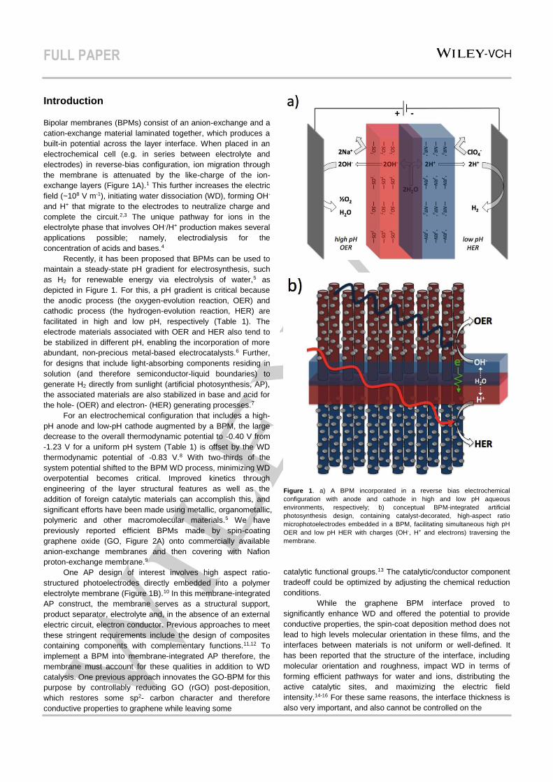
Bipolar membranes (BPMs) consist of an anion-exchange and a
cation-exchange material laminated together, which produces a
built-in potential across the layer interface. When placed in an
electrochemical cell (e.g. in series between electrolyte and
electrodes) in reverse-bias configuration, ion migration through
the membrane is attenuated by the like-charge of the ion-
exchange layers (Figure 1A).1 This further increases the electric
field (~108 V m-1), initiating water dissociation (WD), forming OH-
and H+ that migrate to the electrodes to neutralize charge and
complete the circuit.2,3 The unique pathway for ions in the
electrolyte phase that involves OH-/H+ production makes several
applications possible; namely, electrodialysis for the
concentration of acids and bases.4
Recently, it has been proposed that BPMs can be used to
maintain a steady-state pH gradient for electrosynthesis, such
as H2 for renewable energy via electrolysis of water,5 as
depicted in Figure 1. For this, a pH gradient is critical because
the anodic process (the oxygen-evolution reaction, OER) and
cathodic process (the hydrogen-evolution reaction, HER) are
facilitated in high and low pH, respectively (Table 1). The
electrode materials associated with OER and HER also tend to
be stabilized in different pH, enabling the incorporation of more
abundant, non-precious metal-based electrocatalysts.6 Further,
for designs that include light-absorbing components residing in
solution (and therefore semiconductor-liquid boundaries) to
generate H2 directly from sunlight (artificial photosynthesis, AP),
the associated materials are also stabilized in base and acid for
the hole- (OER) and electron- (HER) generating processes.7
For an electrochemical configuration that includes a high-
pH anode and low-pH cathode augmented by a BPM, the large
decrease to the overall thermodynamic potential to -0.40 V from
-1.23 V for a uniform pH system (Table 1) is offset by the WD
thermodynamic potential of -0.83 V.8 With two-thirds of the
system potential shifted to the BPM WD process, minimizing WD
overpotential becomes critical. Improved kinetics through
engineering of the layer structural features as well as the
addition of foreign catalytic materials can accomplish this, and
significant efforts have been made using metallic, organometallic,
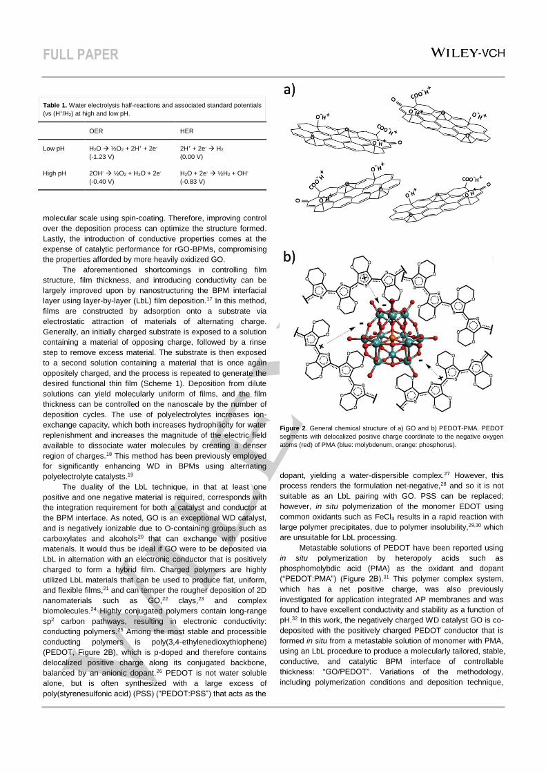
polymeric and other macromolecular materials.5 We have
previously reported efficient BPMs made by spin-coating
graphene oxide (GO, Figure 2A) onto commercially available
anion-exchange membranes and then covering with Nafion
proton-exchange membrane.9
One AP design of interest involves high aspect ratio-
structured photoelectrodes directly embedded into a polymer
electrolyte membrane (Figure 1B).10 In this membrane-integrated
AP construct, the membrane serves as a structural support,
product separator, electrolyte and, in the absence of an external
electric circuit, electron conductor. Previous approaches to meet
these stringent requirements include the design of composites
containing components with complementary functions.11,12 To
implement a BPM into membrane-integrated AP therefore, the
membrane must account for these qualities in addition to WD
catalysis. One previous approach innovates the GO-BPM for this
purpose by controllably reducing GO (rGO) post-deposition,
which restores some sp2- carbon character and therefore
conductive properties to graphene while leaving some
Figure 1. a) A BPM incorporated in a reverse bias electrochemical
configuration with anode and cathode in high and low pH aqueous
environments, respectively; b) conceptual BPM-integrated artificial
photosynthesis design, containing catalyst-decorated, high-aspect ratio
microphotoelectrodes embedded in a BPM, facilitating simultaneous high pH
OER and low pH HER with charges (OH-, H+ and electrons) traversing the
membrane.
catalytic functional groups.13 The catalytic/conductor component
tradeoff could be optimized by adjusting the chemical reduction
conditions.
While the graphene BPM interface proved to
significantly enhance WD and offered the potential to provide
conductive properties, the spin-coat deposition method does not
lead to high levels molecular orientation in these films, and the
interfaces between materials is not uniform or well-defined. It
has been reported that the structure of the interface, including
molecular orientation and roughness, impact WD in terms of
forming efficient pathways for water and ions, distributing the
active catalytic sites, and maximizing the electric field
intensity.14-16 For these same reasons, the interface thickness is
also very important, and also cannot be controlled on the
FULL PAPER
Table 1. Water electrolysis half-reactions and associated standard potentials
(vs (H+/H2) at high and low pH.
OER HER
Low pH H2O → ½O2 + 2H+ + 2e-
(-1.23 V)
2H+ + 2e- → H2
(0.00 V)
High pH 2OH- → ½O2 + H2O + 2e-
(-0.40 V)
H2O + 2e- → ½H2 + OH-
(-0.83 V)
molecular scale using spin-coating. Therefore, improving control
over the deposition process can optimize the structure formed.
Lastly, the introduction of conductive properties comes at the
expense of catalytic performance for rGO-BPMs, compromising
the properties afforded by more heavily oxidized GO.
The aforementioned shortcomings in controlling film
structure, film thickness, and introducing conductivity can be
largely improved upon by nanostructuring the BPM interfacial
layer using layer-by-layer (LbL) film deposition.17 In this method,
films are constructed by adsorption onto a substrate via
electrostatic attraction of materials of alternating charge.
Generally, an initially charged substrate is exposed to a solution
containing a material of opposing charge, followed by a rinse
step to remove excess material. The substrate is then exposed
to a second solution containing a material that is once again
oppositely charged, and the process is repeated to generate the
desired functional thin film (Scheme 1). Deposition from dilute
solutions can yield molecularly uniform of films, and the film
thickness can be controlled on the nanoscale by the number of
deposition cycles. The use of polyelectrolytes increases ion-
exchange capacity, which both increases hydrophilicity for water
replenishment and increases the magnitude of the electric field
available to dissociate water molecules by creating a denser
region of charges.18 This method has been previously employed
for significantly enhancing WD in BPMs using alternating
polyelectrolyte catalysts.19
The duality of the LbL technique, in that at least one
positive and one negative material is required, corresponds with
the integration requirement for both a catalyst and conductor at
the BPM interface. As noted, GO is an exceptional WD catalyst,
and is negatively ionizable due to O-containing groups such as
carboxylates and alcohols20 that can exchange with positive
materials. It would thus be ideal if GO were to be deposited via
LbL in alternation with an electronic conductor that is positively
charged to form a hybrid film. Charged polymers are highly
utilized LbL materials that can be used to produce flat, uniform,
and flexible films,21 and can temper the rougher deposition of 2D
nanomaterials such as GO,22 clays,23 and complex
biomolecules.24 Highly conjugated polymers contain long-range
sp2 carbon pathways, resulting in electronic conductivity:
conducting polymers.25 Among the most stable and processible
conducting polymers is poly(3,4-ethylenedioxythiophene)
(PEDOT, Figure 2B), which is p-doped and therefore contains
delocalized positive charge along its conjugated backbone,
balanced by an anionic dopant.26 PEDOT is not water soluble
alone, but is often synthesized with a large excess of
poly(styrenesulfonic acid) (PSS) (“PEDOT:PSS”) that acts as the
Figure 2. General chemical structure of a) GO and b) PEDOT-PMA. PEDOT
segments with delocalized positive charge coordinate to the negative oxygen
atoms (red) of PMA (blue: molybdenum, orange: phosphorus).
dopant, yielding a water-dispersible complex.27 However, this
process renders the formulation net-negative,28 and so it is not
suitable as an LbL pairing with GO. PSS can be replaced;
however, in situ polymerization of the monomer EDOT using
common oxidants such as FeCl3 results in a rapid reaction with
large polymer precipitates, due to polymer insolubility,29,30 which
are unsuitable for LbL processing.
Metastable solutions of PEDOT have been reported using
in situ polymerization by heteropoly acids such as
phosphomolybdic acid (PMA) as the oxidant and dopant
(“PEDOT:PMA”) (Figure 2B).31 This polymer complex system,
which has a net positive charge, was also previously
investigated for application integrated AP membranes and was
found to have excellent conductivity and stability as a function of
pH.32 In this work, the negatively charged WD catalyst GO is co-
deposited with the positively charged PEDOT conductor that is
formed in situ from a metastable solution of monomer with PMA,
using an LbL procedure to produce a molecularly tailored, stable,
conductive, and catalytic BPM interface of controllable
thickness: “GO/PEDOT”. Variations of the methodology,
including polymerization conditions and deposition technique,
FULL PAPER
are explored to optimize the WD catalysis efficiency in an
electrochemical system.
Results and Discussion
Evaluation of LbL Deposition. The procedure for formation of
GO/PEDOT films by LbL involves the in situ synthesis of
PEDOT-PMA, for which variables such as reaction time and
monomer-oxidant ratios must also be considered. Therefore,
three different LbL procedures were designed and tested to find
the optimal conditions, which ultimately are determined by the
resulting WD catalytic performances and are affected by the
quality and controllability of the films formed. First, reaction time
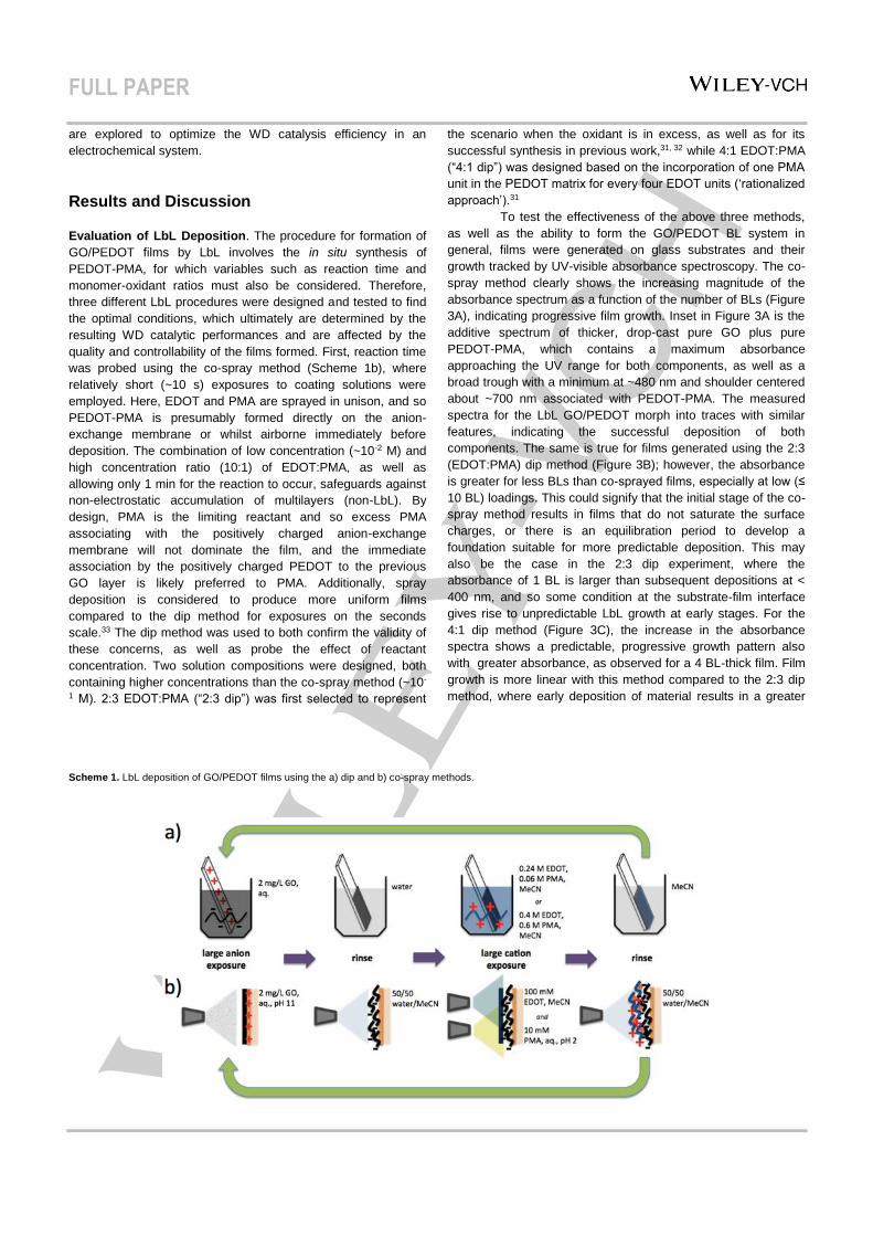
was probed using the co-spray method (Scheme 1b), where
relatively short (~10 s) exposures to coating solutions were
employed. Here, EDOT and PMA are sprayed in unison, and so
PEDOT-PMA is presumably formed directly on the anion-
exchange membrane or whilst airborne immediately before
deposition. The combination of low concentration (~10-2 M) and
high concentration ratio (10:1) of EDOT:PMA, as well as
allowing only 1 min for the reaction to occur, safeguards against
non-electrostatic accumulation of multilayers (non-LbL). By
design, PMA is the limiting reactant and so excess PMA
associating with the positively charged anion-exchange
membrane will not dominate the film, and the immediate
association by the positively charged PEDOT to the previous
GO layer is likely preferred to PMA. Additionally, spray
deposition is considered to produce more uniform films
compared to the dip method for exposures on the seconds
scale.33 The dip method was used to both confirm the validity of
these concerns, as well as probe the effect of reactant
concentration. Two solution compositions were designed, both
containing higher concentrations than the co-spray method (~10-
1 M). 2:3 EDOT:PMA (“2:3 dip”) was first selected to represent
the scenario when the oxidant is in excess, as well as for its
successful synthesis in previous work,31, 32 while 4:1 EDOT:PMA
(“4:1 dip”) was designed based on the incorporation of one PMA
unit in the PEDOT matrix for every four EDOT units (‘rationalized
approach’).31
To test the effectiveness of the above three methods,
as well as the ability to form the GO/PEDOT BL system in
general, films were generated on glass substrates and their
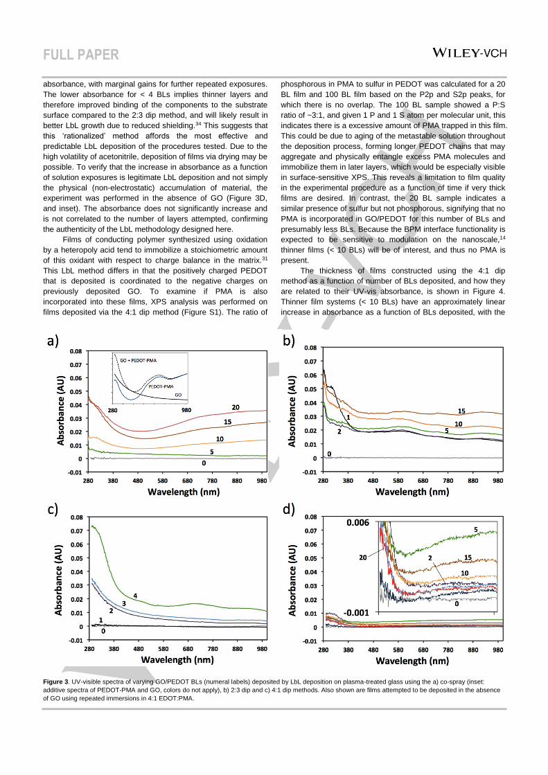
growth tracked by UV-visible absorbance spectroscopy. The co-
spray method clearly shows the increasing magnitude of the
absorbance spectrum as a function of the number of BLs (Figure
3A), indicating progressive film growth. Inset in Figure 3A is the
additive spectrum of thicker, drop-cast pure GO plus pure
PEDOT-PMA, which contains a maximum absorbance
approaching the UV range for both components, as well as a
broad trough with a minimum at ~480 nm and shoulder centered
about ~700 nm associated with PEDOT-PMA. The measured
spectra for the LbL GO/PEDOT morph into traces with similar
features, indicating the successful deposition of both
components. The same is true for films generated using the 2:3
(EDOT:PMA) dip method (Figure 3B); however, the absorbance
is greater for less BLs than co-sprayed films, especially at low (≤
10 BL) loadings. This could signify that the initial stage of the co-
spray method results in films that do not saturate the surface
charges, or there is an equilibration period to develop a
foundation suitable for more predictable deposition. This may
also be the case in the 2:3 dip experiment, where the
absorbance of 1 BL is larger than subsequent depositions at <
400 nm, and so some condition at the substrate-film interface
gives rise to unpredictable LbL growth at early stages. For the
4:1 dip method (Figure 3C), the increase in the absorbance
spectra shows a predictable, progressive growth pattern also
with greater absorbance, as observed for a 4 BL-thick film. Film
growth is more linear with this method compared to the 2:3 dip
method, where early deposition of material results in a greater
Scheme 1. LbL deposition of GO/PEDOT films using the a) dip and b) co-spray methods.
FULL PAPER
absorbance, with marginal gains for further repeated exposures.
The lower absorbance for < 4 BLs implies thinner layers and
therefore improved binding of the components to the substrate
surface compared to the 2:3 dip method, and will likely result in
better LbL growth due to reduced shielding.34 This suggests that
this ‘rationalized’ method affords the most effective and
predictable LbL deposition of the procedures tested. Due to the
high volatility of acetonitrile, deposition of films via drying may be
possible. To verify that the increase in absorbance as a function
of solution exposures is legitimate LbL deposition and not simply
the physical (non-electrostatic) accumulation of material, the
experiment was performed in the absence of GO (Figure 3D,
and inset). The absorbance does not significantly increase and
is not correlated to the number of layers attempted, confirming
the authenticity of the LbL methodology designed here.
Films of conducting polymer synthesized using oxidation
by a heteropoly acid tend to immobilize a stoichiometric amount
of this oxidant with respect to charge balance in the matrix.31
This LbL method differs in that the positively charged PEDOT
that is deposited is coordinated to the negative charges on
previously deposited GO. To examine if PMA is also
incorporated into these films, XPS analysis was performed on
films deposited via the 4:1 dip method (Figure S1). The ratio of
phosphorous in PMA to sulfur in PEDOT was calculated for a 20
BL film and 100 BL film based on the P2p and S2p peaks, for
which there is no overlap. The 100 BL sample showed a P:S
ratio of ~3:1, and given 1 P and 1 S atom per molecular unit, this
indicates there is a excessive amount of PMA trapped in this film.
This could be due to aging of the metastable solution throughout
the deposition process, forming longer PEDOT chains that may
aggregate and physically entangle excess PMA molecules and
immobilize them in later layers, which would be especially visible
in surface-sensitive XPS. This reveals a limitation to film quality
in the experimental procedure as a function of time if very thick
films are desired. In contrast, the 20 BL sample indicates a
similar presence of sulfur but not phosphorous, signifying that no
PMA is incorporated in GO/PEDOT for this number of BLs and
presumably less BLs. Because the BPM interface functionality is
expected to be sensitive to modulation on the nanoscale,14
thinner films (< 10 BLs) will be of interest, and thus no PMA is
present.
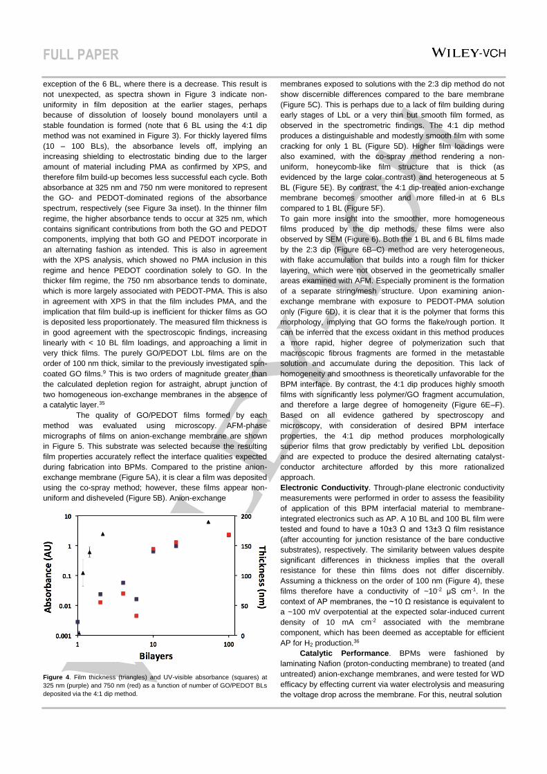
The thickness of films constructed using the 4:1 dip
method as a function of number of BLs deposited, and how they
are related to their UV-vis absorbance, is shown in Figure 4.
Thinner film systems (< 10 BLs) have an approximately linear
increase in absorbance as a function of BLs deposited, with the
Figure 3. UV-visible spectra of varying GO/PEDOT BLs (numeral labels) deposited by LbL deposition on plasma-treated glass using the a) co-spray (inset:
additive spectra of PEDOT-PMA and GO, colors do not apply), b) 2:3 dip and c) 4:1 dip methods. Also shown are films attempted to be deposited in the absence
of GO using repeated immersions in 4:1 EDOT:PMA.
FULL PAPER
exception of the 6 BL, where there is a decrease. This result is
not unexpected, as spectra shown in Figure 3 indicate non-
uniformity in film deposition at the earlier stages, perhaps
because of dissolution of loosely bound monolayers until a
stable foundation is formed (note that 6 BL using the 4:1 dip
method was not examined in Figure 3). For thickly layered films
(10 – 100 BLs), the absorbance levels off, implying an
increasing shielding to electrostatic binding due to the larger
amount of material including PMA as confirmed by XPS, and
therefore film build-up becomes less successful each cycle. Both
absorbance at 325 nm and 750 nm were monitored to represent
the GO- and PEDOT-dominated regions of the absorbance
spectrum, respectively (see Figure 3a inset). In the thinner film
regime, the higher absorbance tends to occur at 325 nm, which
contains significant contributions from both the GO and PEDOT
components, implying that both GO and PEDOT incorporate in
an alternating fashion as intended. This is also in agreement
with the XPS analysis, which showed no PMA inclusion in this
regime and hence PEDOT coordination solely to GO. In the
thicker film regime, the 750 nm absorbance tends to dominate,
which is more largely associated with PEDOT-PMA. This is also
in agreement with XPS in that the film includes PMA, and the
implication that film build-up is inefficient for thicker films as GO
is deposited less proportionately. The measured film thickness is
in good agreement with the spectroscopic findings, increasing
linearly with < 10 BL film loadings, and approaching a limit in
very thick films. The purely GO/PEDOT LbL films are on the
order of 100 nm thick, similar to the previously investigated spin-
coated GO films.9 This is two orders of magnitude greater than
the calculated depletion region for astraight, abrupt junction of
two homogeneous ion-exchange membranes in the absence of
a catalytic layer.35
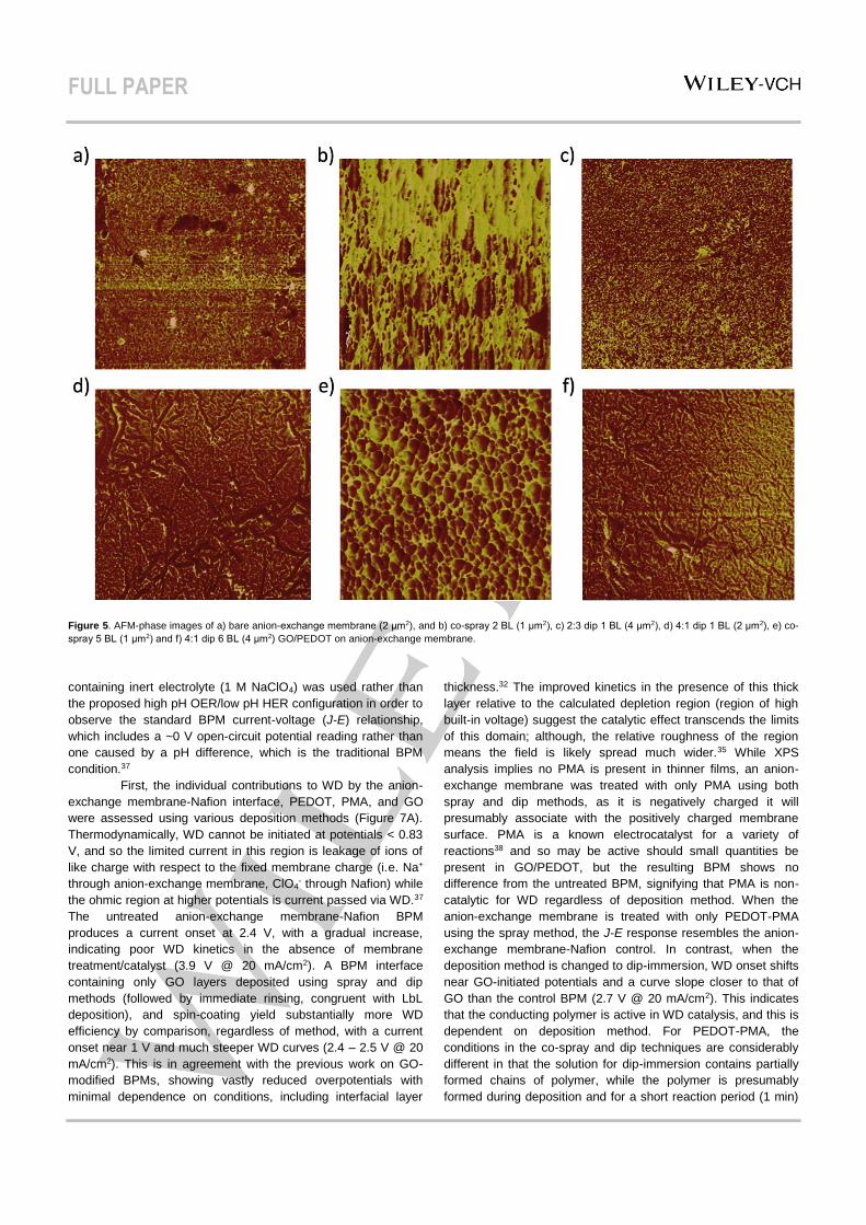
The quality of GO/PEDOT films formed by each
method was evaluated using microscopy. AFM-phase
micrographs of films on anion-exchange membrane are shown
in Figure 5. This substrate was selected because the resulting
film properties accurately reflect the interface qualities expected
during fabrication into BPMs. Compared to the pristine anion-
exchange membrane (Figure 5A), it is clear a film was deposited
using the co-spray method; however, these films appear non-
uniform and disheveled (Figure 5B). Anion-exchange
Figure 4. Film thickness (triangles) and UV-visible absorbance (squares) at
325 nm (purple) and 750 nm (red) as a function of number of GO/PEDOT BLs
deposited via the 4:1 dip method.
membranes exposed to solutions with the 2:3 dip method do not
show discernible differences compared to the bare membrane
(Figure 5C). This is perhaps due to a lack of film building during
early stages of LbL or a very thin but smooth film formed, as
observed in the spectrometric findings. The 4:1 dip method
produces a distinguishable and modestly smooth film with some
cracking for only 1 BL (Figure 5D). Higher film loadings were
also examined, with the co-spray method rendering a non-
uniform, honeycomb-like film structure that is thick (as
evidenced by the large color contrast) and heterogeneous at 5
BL (Figure 5E). By contrast, the 4:1 dip-treated anion-exchange
membrane becomes smoother and more filled-in at 6 BLs
compared to 1 BL (Figure 5F).
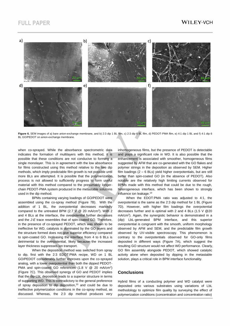
To gain more insight into the smoother, more homogeneous
films produced by the dip methods, these films were also
observed by SEM (Figure 6). Both the 1 BL and 6 BL films made
by the 2:3 dip (Figure 6B–C) method are very heterogeneous,
with flake accumulation that builds into a rough film for thicker
layering, which were not observed in the geometrically smaller
areas examined with AFM. Especially prominent is the formation
of a separate string/mesh structure. Upon examining anion-
exchange membrane with exposure to PEDOT-PMA solution
only (Figure 6D), it is clear that it is the polymer that forms this
morphology, implying that GO forms the flake/rough portion. It
can be inferred that the excess oxidant in this method produces
a more rapid, higher degree of polymerization such that
macroscopic fibrous fragments are formed in the metastable
solution and accumulate during the deposition. This lack of
homogeneity and smoothness is theoretically unfavorable for the
BPM interface. By contrast, the 4:1 dip produces highly smooth
films with significantly less polymer/GO fragment accumulation,
and therefore a large degree of homogeneity (Figure 6E–F).
Based on all evidence gathered by spectroscopy and
microscopy, with consideration of desired BPM interface
properties, the 4:1 dip method produces morphologically
superior films that grow predictably by verified LbL deposition
and are expected to produce the desired alternating catalyst-
conductor architecture afforded by this more rationalized
approach.
Electronic Conductivity. Through-plane electronic conductivity
measurements were performed in order to assess the feasibility
of application of this BPM interfacial material to membrane-
integrated electronics such as AP. A 10 BL and 100 BL film were
tested and found to have a 10±3 Ω and 13±3 Ω film resistance
(after accounting for junction resistance of the bare conductive
substrates), respectively. The similarity between values despite
significant differences in thickness implies that the overall
resistance for these thin films does not differ discernibly.
Assuming a thickness on the order of 100 nm (Figure 4), these
films therefore have a conductivity of ~10-2 μS cm-1. In the
context of AP membranes, the ~10 Ω resistance is equivalent to
a ~100 mV overpotential at the expected solar-induced current
density of 10 mA cm-2 associated with the membrane
component, which has been deemed as acceptable for efficient
AP for H2 production.36
Catalytic Performance. BPMs were fashioned by
laminating Nafion (proton-conducting membrane) to treated (and
untreated) anion-exchange membranes, and were tested for WD
efficacy by effecting current via water electrolysis and measuring
the voltage drop across the membrane. For this, neutral solution
FULL PAPER
Figure 5. AFM-phase images of a) bare anion-exchange membrane (2 μm2), and b) co-spray 2 BL (1 μm2), c) 2:3 dip 1 BL (4 μm2), d) 4:1 dip 1 BL (2 μm2), e) co-
spray 5 BL (1 μm2) and f) 4:1 dip 6 BL (4 μm2) GO/PEDOT on anion-exchange membrane.
containing inert electrolyte (1 M NaClO4) was used rather than
the proposed high pH OER/low pH HER configuration in order to
observe the standard BPM current-voltage (J-E) relationship,
which includes a ~0 V open-circuit potential reading rather than
one caused by a pH difference, which is the traditional BPM
condition.37
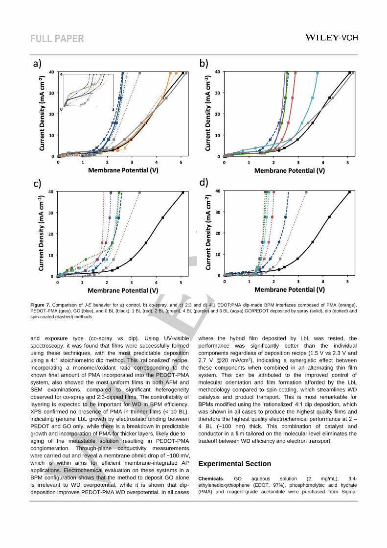
First, the individual contributions to WD by the anion-
exchange membrane-Nafion interface, PEDOT, PMA, and GO
were assessed using various deposition methods (Figure 7A).
Thermodynamically, WD cannot be initiated at potentials < 0.83
V, and so the limited current in this region is leakage of ions of
like charge with respect to the fixed membrane charge (i.e. Na+
through anion-exchange membrane, ClO4- through Nafion) while
the ohmic region at higher potentials is current passed via WD.37
The untreated anion-exchange membrane-Nafion BPM
produces a current onset at 2.4 V, with a gradual increase,
indicating poor WD kinetics in the absence of membrane
treatment/catalyst (3.9 V @ 20 mA/cm2). A BPM interface
containing only GO layers deposited using spray and dip
methods (followed by immediate rinsing, congruent with LbL
deposition), and spin-coating yield substantially more WD
efficiency by comparison, regardless of method, with a current
onset near 1 V and much steeper WD curves (2.4 – 2.5 V @ 20
mA/cm2). This is in agreement with the previous work on GO-
modified BPMs, showing vastly reduced overpotentials with
minimal dependence on conditions, including interfacial layer
thickness.32 The improved kinetics in the presence of this thick
layer relative to the calculated depletion region (region of high
built-in voltage) suggest the catalytic effect transcends the limits
of this domain; although, the relative roughness of the region
means the field is likely spread much wider.35 While XPS
analysis implies no PMA is present in thinner films, an anion-
exchange membrane was treated with only PMA using both
spray and dip methods, as it is negatively charged it will
presumably associate with the positively charged membrane
surface. PMA is a known electrocatalyst for a variety of
reactions38 and so may be active should small quantities be
present in GO/PEDOT, but the resulting BPM shows no
difference from the untreated BPM, signifying that PMA is non-
catalytic for WD regardless of deposition method. When the
anion-exchange membrane is treated with only PEDOT-PMA
using the spray method, the J-E response resembles the anion-
exchange membrane-Nafion control. In contrast, when the
deposition method is changed to dip-immersion, WD onset shifts
near GO-initiated potentials and a curve slope closer to that of
GO than the control BPM (2.7 V @ 20 mA/cm2). This indicates
that the conducting polymer is active in WD catalysis, and this is
dependent on deposition method. For PEDOT-PMA, the
conditions in the co-spray and dip techniques are considerably
different in that the solution for dip-immersion contains partially
formed chains of polymer, while the polymer is presumably
formed during deposition and for a short reaction period (1 min)
FULL PAPER
Figure 6. SEM images of a) bare anion-exchange membrane, and b) 2:3 dip 1 BL film, c) 2:3 dip 6 BL film, d) PEDOT-PMA film, e) 4:1 dip 1 BL and f) 4:1 dip 6
BL GO/PEDOT on anion-exchange membrane.
when co-sprayed. While the absorbance spectrometric data
indicates the formation of multilayers with this method, it is
possible that these conditions are not conducive to forming a
single monolayer. This is in agreement with the low absorbance
for films constructed using this method relative to the two dip
methods, which imply predictable film growth is not possible until
more BLs are attempted. It is possible that the polymerization
process is not allowed to sufficiently progress to form useful
material with this method compared to the presumably longer-
chain PEDOT-PMA system produced in the metastable solutions
used in the dip method.
BPMs containing varying loadings of GO/PEDOT were
assembled using the co-spray method (Figure 7B). With the
addition of 1 BL, the overpotential decreases markedly
compared to the untreated BPM (2.7 V @ 20 mA/cm2). With 2
and 4 BLs at the interface, the overpotential further decreases
and the J-E trace resembles that of spin-coated GO. Therefore,
in the presence of co-sprayed PEDOT, which was shown to be
ineffective for WD, catalysis is dominated by the GO layers and
the structure formed does not give superior efficiency compared
to spin-coated GO. Increasing the interface from 4 to 6 BLs is
detrimental to the overpotential, likely because the increased
layer thickness suppresses ion transport.
When the deposition method was switched from spray
to dip, first with the 2:3 EDOT:PMA recipe, WD on 1 BL
GO/PEDOT considerably further improves upon the co-sprayed
analog, with a lower overpotential than both the dipped PEDOT-
PMA and spin-coated GO references (1.8 V @ 20 mA/cm2)
(Figure 7C). This observed synergy of GO and PEDOT implies
that the dip-LbL deposition leads to a superior structure in terms
of supporting WD. This is contradictory to the general preference
of spray deposition to dip deposition,33 and could be due to
ineffective polymerization conditions in the co-spray method, as
discussed. Whereas, the 2:3 dip method produces very
inhomogeneous films, but the presence of PEDOT is detectable
and plays a significant role in WD. It is also possible that the
enhancement is associated with smoother, homogeneous films
suggested by AFM that are co-generated with the GO flakes and
polymer strings in the deposition as observed by SEM. Higher
film loadings (2 – 6 BLs) yield higher overpotentials, but are still
better than spin-coated GO (in the absence of PEDOT). Also
notable are the relatively high limiting currents observed for
BPMs made with this method that could be due to the rough,
heterogeneous interface, which has been shown to strongly
influence ion leakage.19
When the EDOT:PMA ratio was adjusted to 4:1, the
overpotential is the same as the 2:3 dip method for 1 BL (Figure
7D). However, with higher film loadings the overpotential
decreases further and is optimal with 2 and 4 BLs (1.5 V @20
mA/cm2). Again, the synergistic behavior is demonstrated in a
(dip) LbL-generated BPM interface, and this superior
overpotential is congruent with the smooth, uniform morphology
observed by AFM and SEM, and the predictable film growth
observed by UV-visible spectroscopy. This phenomenon is
contrary to the overpotentials observed for GO-only films
deposited in different ways (Figure 7A), which suggest the
resulting GO structure would not affect WD performance. Clearly,
GO film assembly alongside PEDOT, which showed catalytic
activity alone when deposited by dipping in the metastable
solution, plays a critical role in BPM interface functionality.
Conclusions
Hybrid films of a conducting polymer and WD catalyst were
deposited onto various substrates using variations of LbL
methodology to optimize film quality by surveying the effect of
polymerization conditions (concentration and concentration ratio)
FULL PAPER
Figure 7. Comparison of J-E behavior for a) control, b) co-spray, and c) 2:3 and d) 4:1 EDOT:PMA dip-made BPM interfaces composed of PMA (orange),
PEDOT-PMA (grey), GO (blue), and 0 BL (black), 1 BL (red), 2 BL (green), 4 BL (purple) and 6 BL (aqua) GO/PEDOT deposited by spray (solid), dip (dotted) and
spin-coated (dashed) methods.
and exposure type (co-spray vs dip). Using UV-visible
spectroscopy, it was found that films were successfully formed
using these techniques, with the most predictable deposition
using a 4:1 stoichiometric dip method. This ‘rationalized’ recipe,
incorporating a monomer/oxidant ratio corresponding to the
known final amount of PMA incorporated into the PEDOT-PMA
system, also showed the most uniform films in both AFM and
SEM examinations, compared to significant heterogeneity
observed for co-spray and 2:3-dipped films. The controllability of
layering is expected to be important for WD in BPM efficiency.
XPS confirmed no presence of PMA in thinner films (< 10 BL),
indicating genuine LbL growth by electrostatic binding between
PEDOT and GO only, while there is a breakdown in predictable
growth and incorporation of PMA for thicker layers, likely due to
aging of the metastable solution resulting in PEDOT-PMA
conglomeration. Through-plane conductivity measurements
were carried out and reveal a membrane ohmic drop of ~100 mV,
which is within aims for efficient membrane-integrated AP
applications. Electrochemical evaluation on these systems in a
BPM configuration shows that the method to deposit GO alone
is irrelevant to WD overpotential, while it is shown that dip-
deposition improves PEDOT-PMA WD overpotential. In all cases
where the hybrid film deposited by LbL was tested, the
performance was significantly better than the individual
components regardless of deposition recipe (1.5 V vs 2.3 V and
2.7 V @20 mA/cm2), indicating a synergistic effect between
these components when combined in an alternating thin film
system. This can be attributed to the improved control of
molecular orientation and film formation afforded by the LbL
methodology compared to spin-coating, which streamlines WD
catalysis and product transport. This is most remarkable for
BPMs modified using the ‘rationalized’ 4:1 dip deposition, which
was shown in all cases to produce the highest quality films and
therefore the highest quality electrochemical performance at 2 –
4 BL (~100 nm) thick. This combination of catalyst and
conductor in a film tailored on the molecular level eliminates the
tradeoff between WD efficiency and electron transport.
Experimental Section
Chemicals. GO aqueous solution (2 mg/mL), 3,4-
ethylenedioxythiophene (EDOT, 97%), phosphomolybic acid hydrate
(PMA) and reagent-grade acetonitrile were purchased from Sigma-
FULL PAPER
Aldrich and used without further purification. Water purified by in-house
reverse osmosis was sourced for all experimental steps.
LbL Film Fabrication. Natively uncharged substrates such as glass
(microscope slides, VWR) and Si (wafers, 1-0-0 orientation, N-doped,
WaferPro) were initially cleaned with soap and water, dried under N2
stream, and placed in a O2 PDC-32G Plasma Cleaner (Harrick) at 400
mTorr for 15 min. The positively charged Neosepta AHA anion-exchange
membrane (Ameridia) substrates were rinsed with water and dried in air
without further treatment. Films were constructed on the substrate using
the dip or co-spray methods illustrated in Scheme 1. For PEDOT-PMA
baths, metastable solutions of PEDOT-PMA were made by first
dissolving PMA in 25 mL of acetonitrile under brief sonication, followed
by addition of EDOT in the ratios of 2:3 and 4:1 [EDOT]:[PMA]. For the
dip methods, the baths containing GO were used as-received. Thinner
films (≤ 6 bilayers) (BLs) were fabricated manually, while thicker films
were fabricated automatically using a HMS Series Programmable Slide
Stainer (Carl Zeiss) by immersing the substrate in the alternating baths of
GO and PEDOT/PMA for 1 min, separated by two rinse steps (20 s and
10 s, respectively) in separate solvent-only baths (water for GO,
acetonitrile for PEDOT-PMA), as many times necessary to achieve the
desired number of BLs. For the co-spray method, a custom-built LbL
spray instrument consisting of a rotating stage for the substrate and four
airbrush nozzles controlled manually or by a programmable relay was
used. Four nozzle-compatible containers, each with suction straws, were
filled with: (1) a rinse solution of 50/50 v/v water/ acetonitrile; (2) as-
received GO solution with pH adjusted to 11 using 1 M NaOH; (3) 100
mM EDOT in acetonitrile; and (4) 10 mM PMA in water with pH adjusted
to 2 using 1 M H2SO4. The substrate was mounted on a PTFE rotating
stage and the nozzles were sprayed in the cycle order of: GO, rinse,
EDOT and PMA in concert, rinse, and was repeated as many times
necessary to achieve the desired number of BLs. The approximate time
for each spray was 5 – 10 s for the coating solutions, and 15 – 20 s for
rinsing. After each EDOT/PMA spray, there was a 1 min pause to allow
polymerization.
LbL Film Characterization. BL accumulation was monitored by
intermittently measuring the UV-visible light absorbance of films
deposited on glass substrates using a DU 800 spectrophotometer
(Beckman Coulter). Atomic force microscopy (AFM) studies of films
deposited on anion-exchange membrane were carried out on a
Nanoscope V with a Dimension 3100 D3005-1 detector (Veeco) in
tapping mode using a 6 N/m cantilever (Bruker). Scanning electron
microscopy (SEM) of films on anion-exchange membrane utilized a
6010LA instrument (JEOL) with SEI detector at 20 kV. Film thicknesses
were measured using a 633 nm wavelength variable angle ellipsometer
(Gaertner Scientific) on FTO (on glass) substrates with the glass
backside painted with red nail polish,39 and assuming a thickness of 340
nm and an index of refraction of 2.4 for the specific FTO product used.40
X-ray photoelectron spectroscopy (XPS) was collected on a Versaprobe
II (Phi Physical Electronics) instrument. Electronic conductivities of films
produced by the 4:1 dip method were measured by depositing the film on
> 1 cm2 of 1 × 3 cm FTO-glass substrates and clamping a pristine FTO-
glass piece of the same dimensions perpendicularly to form a 1 cm2
contact area. The exposed pristine FTO terminals were connected to a
263A Potentiostat/Galvanostat (Princeton Applied Research) in a 2-
electrode configuration and voltage was scanned between 0 and 10 V
(Figure S2). The slope of the resulting current-voltage relationships was
used to derive the electrical resistance, and then used with the
known/estimated dimensions of the film to calculate the conductivity
values over several samples.
BPM Fabrication. In-house BPMs were fabricated similar to previously
described.9, 13 LbL-modified (and unmodified) anion-exchange
membranes (4 × 4 cm) were fastened to glass substrates using electrical
tape. A protective layer of Nafion (5 wt% in water/alcohols, Sigma-
Aldrich) was spin-coated on the film at 2000 rpm for 5 min using a SCS
6800 Spin Coater (SCS Coatings) and heated at 100°C on a hotplate for
10 min. Following, several drops of Nafion solution (10 wt% in water,
Sigma-Aldrich) were placed on the previous Nafion protective layer to
form an adhesion layer with a fully hydrated, pre-formed Nafion NR-211
sheet (Ion Power Inc.), which was draped over the surface to form the
cation-exchange side of the BPM. BPMs were dried overnight in ambient
conditions.
Electrochemical Evaluation. BPMs were removed from the glass
substrates and cut out of the electrical tape frame with shears.
Membranes were placed between two symmetric custom glass chambers
outfitted with Luggin capillaries and custom gaskets formed by casting
liquid electrical tape on the flanges (Department of Chemistry Glass
Shop, University of Manitoba), and bound tightly with a bar clamp to form
an H-cell. Two platinum working electrodes were fabricated using 1 cm2
Pt foil (0.05 mm, 99.9%, Sigma-Aldrich) fixed to copper wire with silver
epoxy (Grainger), sealed in glass tubing with epoxy (Devcon), and placed
in the outer H-cell chambers as current generators. Saturated calomel
reference electrodes (CH Instruments) were placed in the inner Luggin
compartments to measure membrane voltage. Both chambers were filled
with 1 M NaClO4 aqueous electrolyte and allowed to soak into the
membranes for at least 5 hr. The current density-voltage relationship was
discerned by passing galvanostatic currents using a 263A
Potentiostat/Galvanostat (Princeton Applied Research) in increments of
30 min progressive steps between 0 and 80 mA/cm2, corrected for an
exposed membrane area of 2.54 cm2, with 20 min breaks (no applied
current) in between to equilibrate voltage.
Acknowledgements
This work was supported by NSF under the NSF CCI Solar
Fuels Program under Grant No. CHE-1305124.
Keywords: bipolar membranes • layer-by-layer • artificial
photosynthesis • solar fuels • graphene oxide • conducting
polymers • PEDOT • heteropoly acid • phosphomolybdic acid
1. T. W. Xu, Resour., Conserv. Recycl. 2002, 37, 1-22.
2. R. Simons, Electrochim. Acta 1985, 30, 275-282.
3. P. Ramirez, H. J. Rapp, S. Reichle, H. Strathmann, S. Mafe, J. Appl.
Phys. 1992, 72, 259-264.
4. H. Strathmann, Desalination 2010, 264, 268-288.
5. M. B. McDonald, S. Ardo, N. S. Lewis, M. S. Freund, ChemSuSchem
2014, 7, 3021-3027.
6. H. Gerischer, J. Electroanal. Chem. Interfacial Electrochem. 1977, 82,
133-143.
7. M. G. Walter, E. L. Warren, J. R. McKone, S. W. Boettcher, Q. X. Mi, E.
A. Santori, N. S. Lewis, Chem. Rev. 2010, 110, 6446-6473.
8. R. Elmoussaoui, G. Pourcelly, M. Maeck, H. D. Hurwitz, C. Gavach, J.
Membr. Sci. 1994, 90, 283-292.
9. M. B. McDonald, M. S. Freund, ACS Appl. Mater. Interfaces 2014, 6,
13790-13797.
10. H. B. Gray, Nat. Chem. 2009, 1, 7.
11. S. L. McFarlane, B. A. Day, K. McEleney, M. S. Freund, N. S. Lewis,
Energy Environ. Sci. 2011, 4, 1700-1703.
12. J. Y. Liu, N. R. Davis, D. S. Liu, P. T. Hammond, J. Mater. Chem. 2012,
22, 15534-15539.
13. M. B. McDonald, J. P. Bruce, K. McEleney, M. S. Freund,
Chemsuschem 2015, 8, 2645-2654.
14. J. Balster, S. Srinkantharajah, R. Sumbharaju, I. Punt, R. G. H.
Lammertink, D. F. Stamatialis, M. Wessling, J. Membr. Sci. 2010, 365,
389-398.
15. S. Mafe, P. Ramirez, A. Alcaraz, Chem. Phys. Lett. 1998, 294, 406-412.
FULL PAPER
16. H. Strathmann, J. J. Krol, H. J. Rapp, G. Eigenberger, J. Membr. Sci.
1997, 125, 123-142.
17. K. Ariga, J. P. Hill, Q. M. Ji, Phys. Chem. Chem. Phys. 2007, 9, 2319-
2340.
18. M. S. Kang, Y. J. Choi, S. H. Kim, S. H. Moon, J. Membr. Sci. 2004,
229, 137-146.
19. S. Abdu, K. Sricharoen, J. E. Wong, E. S. Muljadi, T. Melin, M.
Wessling, ACS Appl. Mater. Interfaces 2013, 5, 10445-10455.
20. S. Mao, H. H. Pu, J. H. Chen, RSC Advances 2012, 2, 2643-2662.
21. P. T. Hammond Adv. Mater. 2004, 16, 1271-1293.
22. S. H. Lee, J. R. Harding, D. S. Liu, J. M. D'Arcy, Y. Shao-Horn, P. T.
Hammond, Chem. Mater. 2014, 26, 2579-2585.
23. P. Podsiadlo, B. S. Shim, N. A. Kotov, Coord. Chem. Rev. 2009, 253,
2835-2851.
24. S. Correa, K. Y. Choi, E. C. Dreaden, K. Renggli, A. Shi, L. Gu, K. E.
Shopsowitz, M. A. Quadir, E. Ben-Akiva, P. T. Hammond, Adv. Funct.
Mater. 2016, 26, 991-1003.
25. M. S. Freund, B. A. Deore in Self-Doped Conducting Polymers. John
Wiley & Sons, Ltd, Chichester, UK, 2007, pp. 338.
26. S. Kirchmeyer, K. Reuter, J. Mater. Chem. 2005, 15, 2077-2088.
27. H. Shi, C. C. Liu, Q. L. Jiang, J. K. Xu, Adv. Electron. Mater. 2015, 1,
16.
28. D. Wakizaka, T. Fushimi, H. Ohkita, S. Ito, Polymer 2004, 45, 8561-
8565.
29. A. M. Osterholm, J. F. Ponder, J. A. Kerszulis, J. R. Reynolds, ACS
Appl. Mater. Interfaces 2016, 8, 13492-13498.
30. E. Bravo-Grimaldo, S. Hachey, C. G. Cameron, M. S. Freund, 2007, 40,
7166-7170.
31. S. L. McFarlane, B. A. Deore, N. Svenda, M. S. Freund,
Macromolecules 2010, 43, 10241-10245.
32. M. B. McDonald, M. S. Freund, ACS Appl. Mater. Interfaces 2011, 3,
1003-1008.
33. A. Izquierdo, A.; S. S. Ono, J. C. Voegel, P. Schaaf, G. Decher,
Langmuir 2005, 21, 7558-7567.
34. B. N. Balzer, S. Micciulla, S. Dodoo, M. Zerball, M. Gallei, M. Rehahn,
R. von Klitzing, T. Hugel, ACS Appl. Mater. Interfaces 2013, 5, 6300-
6306.
35. M. Unlu, J. F. Zhou, P. A. Kohl, J. Phys. Chem. C 2009, 113, 11416-
11423.
36. S. Chabi, K. M. Papadantonakis, N. S. Lewis, M. S. Freund, Energy
Environ. Sci. 2017, 10, 1320-1338.
37. F. G. Wilhelm, I. Punt, N. F. A. van der Vegt, M. Wessling, H.
Strathmann, J. Membr. Sci. 2001, 182, 13-28.
38. D. E. Katsoulis, Chem. Rev. 1998, 98, 359-387.
39. R. A. Synowicki, Phys. Status Solidi C 2008, 5, 1085-1088.
40. K. vonRottkay, M. Rubi in Optical indices of pyrolytic tin-oxide glass,
Symposium on Thin Films for Photovoltaic and Related Device
Applications, Materials Research Society, San Francisco, CA, 1996, pp.
449-454.
FULL PAPER
FULL PAPER
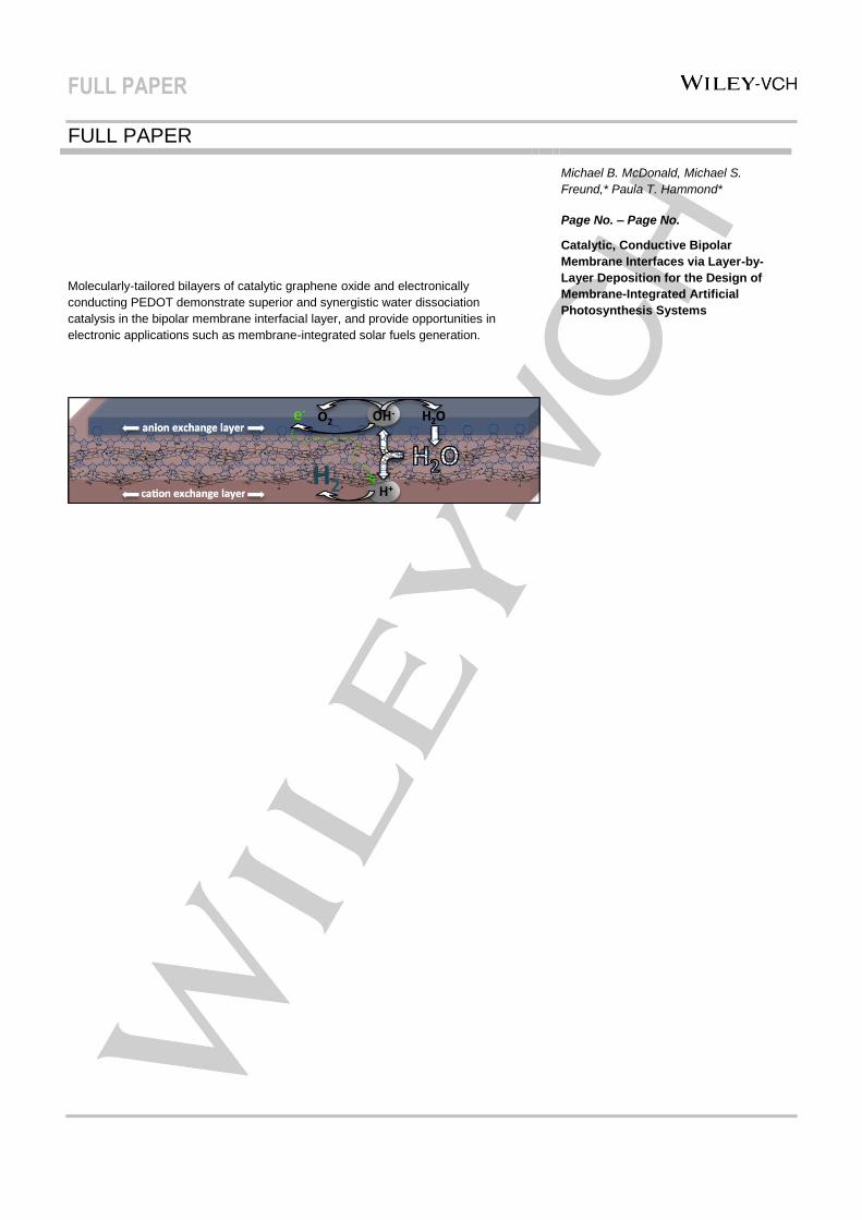
Molecularly-tailored bilayers of catalytic graphene oxide and electronically
conducting PEDOT demonstrate superior and synergistic water dissociation
catalysis in the bipolar membrane interfacial layer, and provide opportunities in
electronic applications such as membrane-integrated solar fuels generation.
Michael B. McDonald, Michael S.
Freund,* Paula T. Hammond*
Page No. – Page No.
Catalytic, Conductive Bipolar
Membrane Interfaces via Layer-by-
Layer Deposition for the Design of
Membrane-Integrated Artificial
Photosynthesis Systems