Embed Size (px)
Citation preview

CATEGORIZATION OF EUROPEAN GASIFICATION TECHNOLOGIES
This project has received funding from the European Union´s Horizon 2020 research and innovation programme under grant agreement N° 857804. The sole responsibility for the content of this document lies with the authors. It does not necessarily reflect the opinion of the EU.
AUTHOR: FRANZ KIRCHMEYR (AKBOE)

2
This project has received funding from the European Union´s Horizon 2020 research and innovation programme under grant agreement N° 857804. The sole responsibility for the content of this document lies with the authors. It does not necessarily reflect the opinion of the EU.
EXECUTIVE SUMMARY OF D2.2
The following document provides an overview of existing European gasification technologies and the main gasification processes.
After the introductory section on biomass conversion processes, the text follows the logic of the wood gas production process, progressing from the various gasifier technologies to feedstock specifics, storage, and necessary pre-treatment. Special, detailed chapters on issues of particular relevance for all gasification plants are included (e.g. on measurement, control and regulation technologies).
Due to the amount of existing information available on this topic, it may be the case that not everything is included or considered extensively. This document is intended as a solid starting point in learning about gasification. It cannot replace specialised training courses or professional planning. Some additional technologies and applications relevant for gasification have already been outlined in the document ‘Overview and Categorisation of European Biogas Technologies focusing on Anaerobic Digestion’.
The detailed descriptions of certain technologies do not imply any preference for a specific technology, service provider or device. Similarly, pictures showing company names are included for visualisation purposes only and should not be seen as an endorsement of any specific company or technology.

3
This project has received funding from the European Union´s Horizon 2020 research and innovation programme under grant agreement N° 857804. The sole responsibility for the content of this document lies with the authors. It does not necessarily reflect the opinion of the EU.
SUMMARY OF THE DIBICOO PROJECT
The Digital Global Biogas Cooperation (DiBiCoo) project is part of the EU’s Horizon 2020 Societal Challenge ‘Secure, clean and efficient energy’, under the heading ‘Market Uptake Support’.
The target emerging and developing importing countries are Argentina, Ethiopia, Ghana, South Africa and Indonesia. Additionally, the project involves partners from Germany, Austria, Belgium and Latvia. The project started in October 2019 with a 33-month timeline and a budget of 3 Million Euros. It is implemented by the consortium and coordinated by the German Society for International Cooperation (Deutsche Gesellschaft für Internationale Zusammenarbeit, or GIZ) GmbH.
The overall objective of the project is to prepare markets in developing and emerging countries for the import of sustainable biogas/biomethane technologies from Europe. DiBiCoo aims to benefit both importing and exporting countries by facilitating dialogue between European biogas industries and biogas stakeholders or developers from emerging and developing markets. The consortium is working to advance knowledge transfer and experience sharing, with the aim of improving local policies so as to allow increased market uptake by target countries. This is facilitated via a digital matchmaking platform and classical capacity development mechanisms for improved networking, information sharing and technical/financial competencies. Furthermore, DiBiCoo will identify five demo cases up to the investment stages in the 5 importing countries. In this way, the project will help to mitigate GHG emissions and increase the share of renewable energy generation in the global energy mix. The project also contributes to the UN Sustainable Development Goals (SDG 7) for ‘Affordable and clean energy’, among others.
Further information can be found on the DiBiCoo website: www.dibicoo.org.

4
This project has received funding from the European Union´s Horizon 2020 research and innovation programme under grant agreement N° 857804. The sole responsibility for the content of this document lies with the authors. It does not necessarily reflect the opinion of the EU.
CONTENT
Executive Summary of D2.2 2
Summary of the DiBiCoo Project 3
Content 4
List of abbreviations 5
List of figures 6
List of pictures 7
List of tables 8
1. Introduction to gasification 9
1.1 General description of biomass conversion processes 12
1.2 Why the gasification of wooden biomass? 17
2. Differentiation and characterisation of different gasification processes 18
2.1 Fixed bed gasifier 19
2.1.1 Fixed bed downdraft gasifier 23
2.1.2 Fixed bed updraft gasifier 23
2.1.3 Special designs: double staged fixed bed gasifier 24
2.2 Fluidised bed gasifier 26
2.2.1 Stationary fluidised bed 26
2.2.2 Circulating fluidised bed 26
3. Feedstocks: specification, storage, pretreatment and handling 28
3.1 Feedstock specifications and characteristics 28
3.1.1 Main components 28
3.1.2 Ash melting point 29
3.1.3 Energy content and the influence of water content 29
3.2 Feedstock requirements for use in gasifiers 32
3.2.1 Feedstock size and fine dust 32
3.2.2 Water content 34
4. Products of gasification 36
4.1 Wood gas 36
4.2 Ash and/or charcoal 41
5. MCR: measurement, control and regulation techniques and safety equipment 44
References 47
5
This project has received funding from the European Union´s Horizon 2020 research and innovation programme under grant agreement N° 857804. The sole responsibility for the content of this document lies with the authors. It does not necessarily reflect the opinion of the EU.
LIST OF ABBREVIATIONS
Combined heat and power unit
Heating value inferior or caloric valueChemical bound energy in fuel which can be set free through afull combustion process where the temperature of exhaust gas has 25 °C and possible vapor is not condensed.[MJHi kg-1; MJHi l
-1]
Heating value superior or gross calorific valueChemical bound energy in fuel which can be set free through afull combustion process where the temperature of exhaust gashas 25 °C and possible vapor is condensed.[MJHs kg-1; MJHs l
-1]
Lambda or excess air figure:ratio between added air to a combustion process to the neededair for a full stoichiometric combustion of all combustible elements.lambda = 1: exactly amount of air is added to the combustionprocess which is needed for full stoichiometric combustion of allcombustible elementsLambda > 1: more oxygen is added to the combustion processas needed for combustion of all combustible elements
Low Calorific Value Gas
m³ at:temperature: 0°Cpressure: 1 013 mbar
CHP
Hi
Hs
λ
LCV
Nm³

6
This project has received funding from the European Union´s Horizon 2020 research and innovation programme under grant agreement N° 857804. The sole responsibility for the content of this document lies with the authors. It does not necessarily reflect the opinion of the EU.
LIST OF FIGURESFigure 1: Development of the efficiency (η) of new wood fired boilers during type approval expressed in [%]; © Baumgartner, 2020. 10
Figure 2: Development of carbon monoxide emissions of new wood fired boilers during type approval expressed in CO emissions [mgCO Nm-3] © Baumgartner, 2020. 11
Figure 3: Development of particulate matter emissions in new wood fired boilers [mgPM MJ-1] © Schwarz, 2019. 11
Figure 4: Theory of full combustion of wooden biomass. 14
Figure 5: Theory of energy flow within a gasification process. Input thermal energy can come from part-ly combustion of wooden biomass (autothermal) or can be delivered from external source (allothermal). The thickness of arrows shows the main flows. 16
Figure 6: Theory of the energy flow within a pyrolysis process. 17
Figure 7: Types of gasifier techniques and their usual range of performance © IEA, 2014. 19
Figure 8: Process steps of gasification © Sikarwar, 2016. 20
Figure 9: Scheme of a downdraft fixed bed gasifier © A. Gandhi, 2012. 23
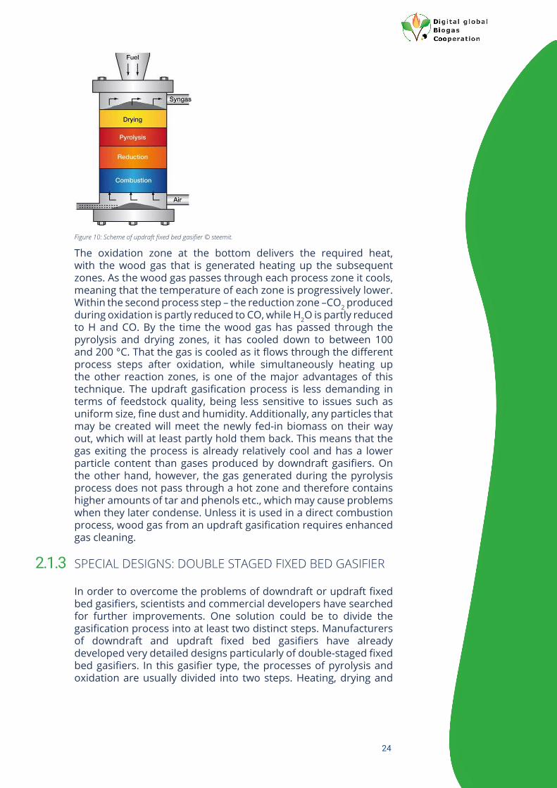
Figure 10: Scheme of updraft fixed bed gasifier © steemit. 24
Figure 11 :Double staged gasification process; left: updraft pyrolysis; right updraft floating bed reactor © syncraft. 25
Figure 12: Types of different fluidized bed gasifiers © boilersinfo.com, 2018. 27
Figure 13: Schema of Fast Internally Circulating Fluidized Bed gasification (FICFB gasification) process © Hofbauer H. 2002. 27
Figure 14: Firing temperature of wooden biomass depending on water content and excess air content © Nußbaumer, 2000. 34
Figure 15: Typical concentrations of contaminants within wood gas © Aranda Almansa, 2019. 38

7
This project has received funding from the European Union´s Horizon 2020 research and innovation programme under grant agreement N° 857804. The sole responsibility for the content of this document lies with the authors. It does not necessarily reflect the opinion of the EU.
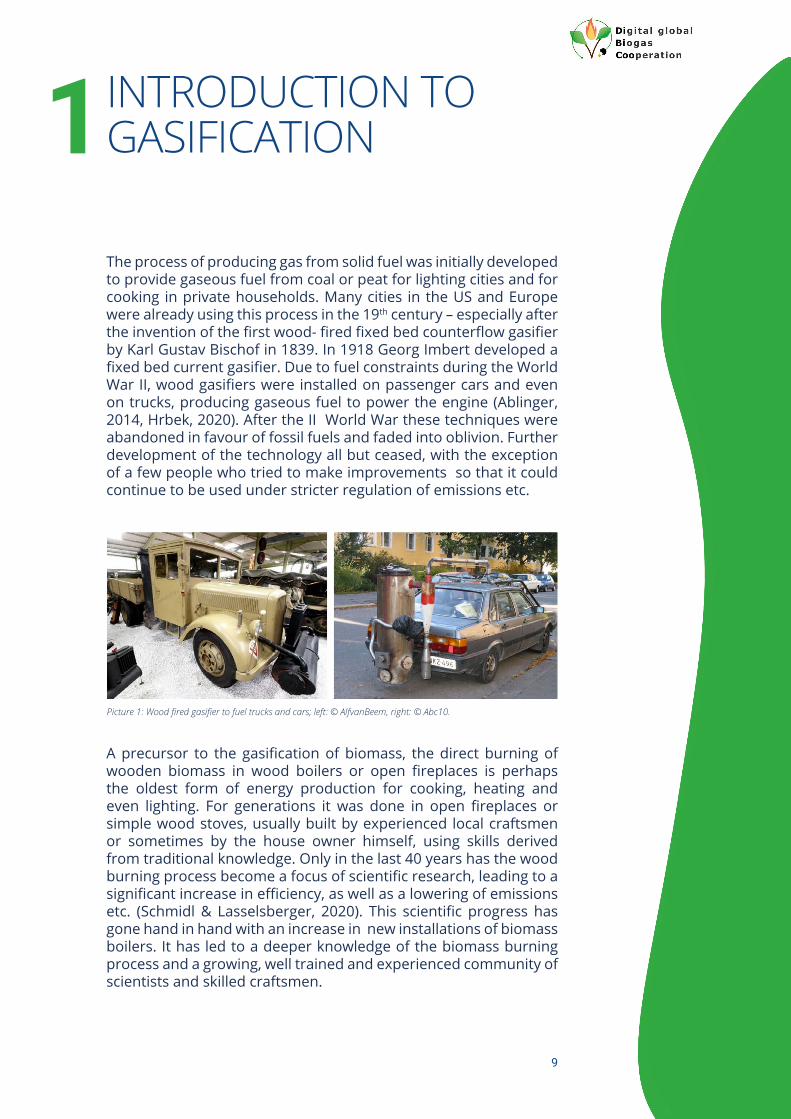
LIST OF PICTURESPicture 1: Wood fired gasifier to fuel trucks and cars; left: © AlfvanBeem, right: © Abc10. 9
Picture 2: Biomass burning in open fireplaces. 10
Picture 3: Process steps of biomass combustion: left: gaseous fuel passes out of heated up wooden biomass; right: burning of gaseous fuel. 14
Picture 4: Process steps of biomass combustion. Differentiated supply of primary and secondary air for full com-bustion of gaseous fuel (primary air below stochiometric conditions, secondary air over stochiometric conditions). 15
Picture 5: Process steps of biomass combustion: remaining charcoal combusts with a short light blue flame and at least without any flame like barbecue coal does. 15
Picture 6: Gasification and combustion of wooden biomass 16
Picture 7: Safety devices upfront of the gasifier: top left: double valves; top right: combination of slider and air cushion; bottom left: double slider; bottom right auger screw into gasifier. 20
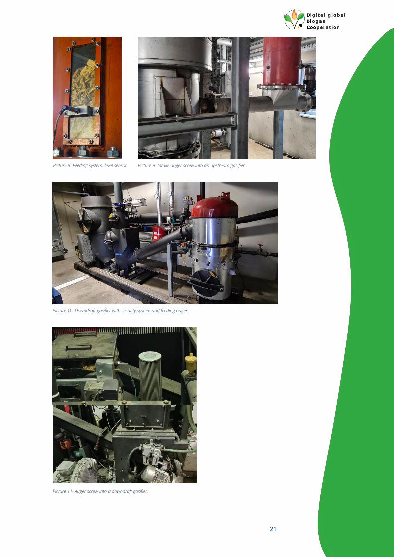
Picture 8: Feeding system: level sensor. 21
Picture 9: Intake auger screw into an upstream gasifier. 21
Picture 10: Downdraft gasifier with security system and feeding auger. 21
Picture 11: Auger screw into a downdraft gasifier. 21
Picture 12: View of fixed bed gasifier; left: 50 kWel. right: 150 kWel. (only bottom part). 22
Picture 13: Downdraft fixed bed gasifier: left: coat of gasifier with air pipes; right: insight from
bottom. 22
Picture 14: Rotating grate of a fixed bed downstream gasifier: left: taken apart; righ: assembled. 22
Picture 15: Left updraft pyrolysis with auger screw to move biomass upwards, drop shaft and floating bed reactor; right: bottom of floating bed reactor with oxidation flame and impurities disposal at the base. 25
Picture 16: Fast Internally Circulating Fluidized Bed gasification plant in Güssing, Austria: left: whole plant; right: bottom of gasifier and autothermic bed recirculation chamber. 27
Picture 17: Different piles of chipped wood before sieving. 33
Picture 18: Left: fine dust, right: oversized particles after sieving. 33
Picture 19: Sieved wood chips. 33
Picture 20: Drum sieve. 33
Picture 21: Auger with welded on knife of an auger chipper. 34
Picture 22: Left: grate dryer with sliding floor and air pipes, right: perforated floor. 35
Picture 23: Belt dryer. 35
Picture 24: From left to right: cyclone, single cartridge of a cartridge filter, cartridge filter with automatic cleaning device, baghouse filter. 40
Picture 25: CHP unit to produce combined heat and power from wood gas. 41
Picture 26: Left: ash of full combusted wood; right: raw charcoal. 42
Picture 27: From left to right: ash transporting device with double security valve, humidification device avoiding dust and self-ignition, humidified ash, hot dry ash. 43
Picture 28: Untreated charcoal, charcoal can with labelling, filling station for charcoal into big bags. 43
Picture 29: Sensor to check the filling level and to secure the feedstock conveying system. 44
Picture 30: Left: delinking of ambient air to the gasifier via water barrier, right: torch. 45
Picture 31: Sensor to check the gasification process. 45
Picture 32: Visualisation of the measurement, control and regulation unit. 45
Picture 33: Hazard Plan. 46
Picture 34: Fix installed safety devices (gas and flame detection). 46
Picture 35: Handheld safety device to detect different types of gases (toxic, explosive). 46

8
This project has received funding from the European Union´s Horizon 2020 research and innovation programme under grant agreement N° 857804. The sole responsibility for the content of this document lies with the authors. It does not necessarily reflect the opinion of the EU.
LIST OF TABLESTable 1: Products of different biomass conversion technologies depending on excess air, Hi: Heating value inferior © Kaltschmitt, 2008. 13
Table 2: Process differentiation exotherm vs. endotherm reaction © Kaltschmitt, 2016. 13
Table 3: Process steps of biomass combustion, conditions, products and contribution to the reached energy out-put © Kaltschmitt, 2016. 13
Table 4: Differentiation of different types of gasification technologies. 18
Table 5: Main ingredients of biomass fuel [%m, w=0] © Beckmann, 2007; Kaltschmitt, 2016; Obern-berger, 2001; Eltrop, 2014. 29
Table 6: Ash melting points of different feedstocks © Eltrop, 2014; Kaltschmitt 2016. 29
Table 7: Difference in reference base between water content and moisture content. 30
Table 8: Energy content of different types of biomass feedstock, Hi: heating value inferior, Hs: heating value superior © Obernberger, 2001; Kaltschmitt, 2016. 30
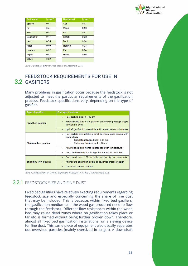
Table 9: Density of different wood species © Kaltschmitt, 2016. 32
Table 10: Requirement on biomass dependent on gasifier technique © IEA bioenergy, 2019. 32
Table 11: General influence of gasification medium to energy, hydrogen and atmospheric nitrogen content of wood gas © Eltrop, 2014. 37
Table 12: Typical composition and energy content of dry wood gas depending on gasification me-dium, values in column = average © Kaltschmitt, 2016; FNR, 2014; Nilsson, 2011. 37
Table 13: Typical ingredients of wood gas divided in components including energy content and without © Kalt-schmitt, 2016. 37
Table 14: Composition of wood gas depending on feedstock at the GoBiGas plant in Sweden © Hrbek, Larsson 2017. 38
Table 15: Usual particle and tar content of raw wood gas depending on gasification type © Kaltsch-mitt, 2016. 39
Table 16: Usual requirement of internal combustion engines running on wood gas © Eltrop, 2014. 39
Table 17: Performance of different types of gas cleaning techniques © Kaltschmitt 2016, Eltrop 2014. 40
Table 18: Composition of different feedstock and received ashes after treatment in large scale gasifier © Fryda, 2015. 41
Table 19: Composition of different types of ashes, their nutrient and heavy metal content and their distribution in bottom ash, cyclone ash and cartridge filter ash © Eltrop 2014. 42
9
INTRODUCTION TO GASIFICATION 1The process of producing gas from solid fuel was initially developed to provide gaseous fuel from coal or peat for lighting cities and for cooking in private households. Many cities in the US and Europe were already using this process in the 19th century – especially after the invention of the first wood- fired fixed bed counterflow gasifier by Karl Gustav Bischof in 1839. In 1918 Georg Imbert developed a fixed bed current gasifier. Due to fuel constraints during the World War II, wood gasifiers were installed on passenger cars and even on trucks, producing gaseous fuel to power the engine (Ablinger, 2014, Hrbek, 2020). After the II World War these techniques were abandoned in favour of fossil fuels and faded into oblivion. Further development of the technology all but ceased, with the exception of a few people who tried to make improvements so that it could continue to be used under stricter regulation of emissions etc.
A precursor to the gasification of biomass, the direct burning of wooden biomass in wood boilers or open fireplaces is perhaps the oldest form of energy production for cooking, heating and even lighting. For generations it was done in open fireplaces or simple wood stoves, usually built by experienced local craftsmen or sometimes by the house owner himself, using skills derived from traditional knowledge. Only in the last 40 years has the wood burning process become a focus of scientific research, leading to a significant increase in efficiency, as well as a lowering of emissions etc. (Schmidl & Lasselsberger, 2020). This scientific progress has gone hand in hand with an increase in new installations of biomass boilers. It has led to a deeper knowledge of the biomass burning process and a growing, well trained and experienced community of scientists and skilled craftsmen.
Picture 1: Wood fired gasifier to fuel trucks and cars; left: © AlfvanBeem, right: © Abc10.

10
The burning of wooden biomass has progressed from a simple process with a single, uncontrolled air inlet, to a staged combustion process with 2 or even more separately-located inlets for combustion-air, a specially designed combustion chamber and even specialist heat exchangers. This has vastly increased efficiency as well as greatly reducing emissions. If the heat exchangers are designed to condense the vapor contained in the exhaust gas, it is even possible to achieve combustion efficiencies above 100 %. These developments have also decreased emissions of carbon monoxide and particulate matter by over 90%, compared to emissions from boilers produced in the 1980s (Schmidl & Lasselsberger 2020).
Picture 2: Biomass burning in open fireplaces.
Figure 1: Development of the efficiency (η) of new wood fired boilers during type approval expressed in [%]; © Baumgartner, 2020.

11
These advances have been closely associated with discussions on air pollution and climate change. The ever increasing focus on the reduction of greenhouse gas emissions led to, amongst other outcomes, the first renewable energy directive of the European Union. The latest major legislative act is the Paris Agreement 2015, which has been signed by 195 nations so far.
Because early discussions about increasing the share of renewable energies focused predominantly on renewable electricity, the biomass industry started to consider ways of using biomass for electricity production. Alongside other options, further development of gasification techniques was looked at as one possible solution. The continued growth in biomass boiler installations indirectly supported the development of gasification technology, through the broad scientific community and craftsmen with specialist knowledge of wooden biomass burning processes.
Although electricity from wooden biomass can also be produced using steam or organic Rankine cycle processes, this report focuses specifically on biomass gasification processes.
Figure 2: Development of carbon monoxide emissions of new wood fired boilers during type approval expressed in CO emissions [mgCO Nm-3] © Baumgartner, 2020.
Figure 3: Development of particulate matter emissions in new wood fired boilers [mgPM MJ-1] © Schwarz, 2019.
12
GENERAL DESCRIPTION OF BIOMASS CONVERSION PROCESSES
Alongside its great potential for use in construction, interiors and furniture etc., wooden biomass, with its renewable carbon content, is a great renewable energy source. As the energy is chemically bound it can also be seen as great resource for energy storage. According to the European Commission’s 2020 statistical pocketbook, renewables reached a share of 13.5% of the worldwide energy supply in 2018. Within renewables the share of biomass reached 68%, making it by far the most important renewable energy source worldwide in 2018 (European Commission, 2020). Although so far, most wooden biomass for energy production is still used directly for heating and cooking via the combustion process, the gasification of wooden biomass has made huge progress within the last decade.
Categorisation of different biomass conversion technologies depending on excess air figure (lambda):
Within a direct combustion process the principal goal is to combust fully the wooden biomass and thus convert the chemically stored energy within the biomass into thermal energy, with high efficiency and very low emissions. This means that organic carbon should be converted as much as possible into CO2 and exhaust gas should include the lowest possible levels of combustible compounds. The remaining ash should be made up of non-combustible elements like nutrients, trace elements etc. and not contain any further combustible organic carbon. Besides other factors, such as
• temperature• turbulence• time
this is achieved by providing at least 100% of the oxygen needed for complete oxidation of all combustible compounds. Usually, the required oxygen comes from the combustion air. The ratio between the actual combustion air supplied and the minimum combustion air required for full oxidation is called the excess air figure (lambda). A lambda value of 1 signifies that the amount of oxygen within the combustion air exactly matches the amount required to convert fully all combustible elements. Lambda > 1 is when excess combustion air is given to the conversion process (all combustion processes generally run above lambda 1). Lambda < 1 is when not enough oxygen is provided to convert fully all combustible elements (as in gasification or even pyrolysis). This process is used to produce a calorific gas – the wood gas – which can be used in a further combustion process e.g., within a CHP to produce heat and power.
1.1

13
A) Combustion
Even during a straightforward combustion process, wooden biomass does not burn directly as a solid fuel: it is broken down by heat into gases which then combust. When wooden biomass is heated, free and cell-bound water will first be released as vapour. At a temperature of around 150 °C, gaseous fuel will be formed through a pyrolytic process. During this process, macromolecules will be broken down by the heat. Depending on the process conditions, the gaseous fuel produced is usually a gas rich in CO2, CH4, H4 and CO. This gaseous fuel will generally then be ignited but this is still an endothermic process, meaning that the energy released at this stage is too low to keep the process going. At around 250 °C and above, the combustion becomes an exothermic reaction, in which enough energy is released to keep the process going.
Table 1: Products of different biomass conversion technologies depending on excess air, Hi: Heating value inferior © Kaltschmitt, 2008.
Table 2: Process differentiation exotherm vs. endotherm reaction © Kaltschmitt, 2016.
Table 3: Process steps of biomass combustion, conditions, products and contribution to the reached energy out-put © Kaltschmitt, 2016.

14
For a full combustion of wooden biomass, lambda needs to remain above 1 for the duration of the process. Typical modern log wood boilers create a staged combustion process by dividing the required air into primary and secondary air. Primary air is drawn in in sub-stoichiometric conditions, meaning that it is enough to start and maintain the process, but is not sufficient to fully convert all combustible elements. Any fuel gas that is generated during this first step will then be fed into a special combustion chamber where it meets the secondary air to fully combust all combustible elements and produce heat. To reach the highest possible efficiency and to avoid emissions containing combustible compounds, primary and secondary combustion air will always be higher than the theoretically needed 100 % (i.e. lambda > 1). Each additional percentage of excess air must be heated up but does not increase the amount of energy produced, meaning that too much excess air lowers the efficiency of the combustion process. Well-developed combustion processes therefore try to keep the total amount of input air close to lambda 1 (Schmidl; 2020, Kaltschmitt, 2016).
Figure 4: Theory of full combustion of wooden biomass.
Picture 3: Process steps of biomass combustion: left: gaseous fuel passes out of heated up wooden biomass; right: burning of gaseous fuel.

15
The usual goal of wooden biomass combustion is to produce heat for cooking and heating or even to produce steam.
B) Gasification
The combustion of wooden biomass aims to produce heat through a full combustion process. The gasification process, on the other hand, uses an incomplete biomass combustion process to produce a calorific gas which can later be fully combusted. Depending on the process, charcoal may also be produced as a by-product. Gasification can be achieved by lowering the oxygen intake under the amount required for the full combustion of all combustible compounds (lambda λ < 1), meaning that the process stays endothermic. In an endothermic process the activation energy required to start the process exceeds the energy released directly during the process. As a result, without further external energy supply the process would stop. The energy required to continue the process can be supplied through the partial burning of feedstock or generated gas (autothermal) or through external supply of energy (allothermal)
Picture 4: Process steps of biomass combustion. Differentiated supply of primary and secondary air for full com-bu-stion of gaseous fuel (primary air below stochiometric conditions, secondary air over stochiometric conditions).
Picture 5: Process steps of biomass combustion: remaining charcoal combusts with a short light blue flame and at least without any flame like barbecue coal does.

16
like vapour or heated gasification sand etc. The full oxidation of the gas produced will be carried out at a later stage (after gas cleaning) to produce heat, steam, combined heat and power (CHP) or even, after another technical process, biomethane that can be injected into the gas grid. For the partial oxidisation of the wooden biomass that takes place as part of the gasification process, different types of gasification medium can be used. The most common gasification medium is usually air but oxygen or vapour are alternative options. This part of the gasification process is initially endothermic but thereafter strongly exothermic (the energy released is greater than the initial activation energy).
Charcoal, the possible by-product of gasification, is mainly used as a soil conditioner and as activated carbon. It includes nearly all the nutrients originally contained in the feedstock, along with the non-combusted carbon.
Compared to the straightforward combustion of wooden biomass, which plays an age-old and important role in energy supply, gasification has had a patchier history. Interest in the process peaked in the interwar period and during World War II, but then receded. However, it is now seeing a very significant resurgence (Graph 1: Cumulative worldwide capacity of gasification technique © Hrbek, 2020).
Figure 5: Theory of energy flow within a gasification process. Input thermal energy can come from partly combu-stion of wooden biomass (autothermal) or can be delivered from external source (allothermal). The thickness of arrows shows the main flows.
Picture 6: Gasification and combustion of wooden biomass.

17
C) Pyrolysis
The main difference between combustion and gasification in terms of pyrolysis technique is that in gasification processes, the pyrolysis is performed only by applying heat, without any additional external oxygen (lambda = 0). The main products of pyrolysis differ depending on the chosen process, temperature and pressure. The macromolecules of wooden biomass are broken down, producing liquid and gaseous fuels, both of which can then be cleaned, upgraded and used for energy production or new bio-based products.
WHY THE GASIFICATION OF WOODEN BIOMASS?
During recent decades scientists, companies and interested parties have searched for ways to extend the use of wooden biomass for energy purposes. One major goal was to remove the combustion process from the place where the heat is required. In private households etc. this can be done by installing a central heating system and distributing the generated heat via heated air or water-borne central heating, as opposed to using tiled stoves in each room. By installing a district-wide heating system, the location of the boiler to combust wooden biomass can even be moved to the outskirts of a settlement. Another possibility, however, is to only partly combust the wooden biomass, producing a low calorific wood gas. This can be used as a combustible gas at a different location, or to produce heat and electricity in a combined cycle called CHP.
Graph 1: Cumulative worldwide capacity of gasification technique © Hrbek, 2020.
Figure 6: Theory of the energy flow within a pyrolysis process.
1.2

18
DIFFERENTIATION AND CHARACTERISATION OF DIFFERENT GASIFICATION PROCESSES
2In contrast to straightforward combustion, gasification produces a transportable, combustible gas which can then be used at a different location. Although this gas is technically seen as a lower calorific value gas, it offers several opportunities. For example, if the goal is to produce electricity, using gasification can raise the electrical efficiency relative to a conventional steam process (© IEA bioenergy 2014). The gas generated by gasification can be transported; it can be upgraded and used as a renewable natural gas substitute to be injected into the gas grid, or it can be transformed to produce a renewable oil substitute. Gasification is not a better biomass conversion process than combustion per se, but it opens up new possibilities and end-use applications. In recent decades, several different types of gasification technique have been developed, which vary according to size, feedstock and gasifier medium. Furthermore, the endothermic part of the process can be subdivided into designs with an autothermic energy supply, in which the used feedstock is partially combusted to supply the necessary thermal energy, and designs with an allothermal energy supply, in which the necessary thermal energy is supplied externally via vapour, gasification sand etc.
Table 4: Differentiation of different types of gasification technologies.

19
A variety of gasifier designs are described in the sections below, distinguished first and foremost by the different ways in which the feedstock flows through the gasifier. A very wide range of technologies is already available on the market; this report concentrates on fixed bed and fluidised gasifiers, but it is important to note that a broader spectrum of gasification technologies is currently in use.
FIXED BED GASIFIER
In a fixed bed gasifier, the wooden biomass is usually fed into one side of the gasification chamber, where it is broken down, exiting as ash on the opposite site. The flow of biomass is not driven by the oxidant flow etc. If the production of charcoal is also desirable, then the solid end product can be charcoal instead of ash. This is achieved by adjusting the amount of oxidant: the less oxidant, the less thermal energy outcome and the more energy in the wood gas and/or charcoal. In order to be able to control the oxygen level accurately in significantly sub-stoichiometric conditions, the feeding system is usually airtight. This is most commonly achieved via a double slide system – a combination of a slide and an air bellow or a rotary valve. In all cases, safety devices (which detect, for example, a rise in temperature, the filling level etc.) are installed between the two parts of the double slide system. The biomass passes into the gasification chamber under the force of gravity, if fed from above, or by use of an auger screw, if fed from below. Within the gasification chambers the biomass will go through several process steps, namely:
• Heating and drying• Pyrolysis• Oxidation• Reduction
If the biomass flow is from top to bottom, it usually relies on the force of gravity. The opposite direction of flow can be achieved
Figure 7: Types of gasifier techniques and their usual range of performance © IEA, 2014.
2.1

20
by using an auger screw or similar. The gasification medium and also the wood gas produced can flow in the same direction as the biomass. This is then called a downdraft gasifier. If the flow direction of the gasification medium and the wood gas goes against the biomass flow, then it is referred to as an updraft gasifier. A general description of these different styles of gasifier is given under the subheadings below. Depending on the goal of the gasification process, carbon from wooden biomass can be almost fully or only partly oxidised. Partial oxidation produces a charcoal which can be used for other purposes.
Figure 8: Process steps of gasification © Sikarwar, 2016.
Picture 7: Safety devices upfront of the gasifier: top left: double valves; top right: combination of slider and air cushion; bottom left: double slider; bottom right auger screw into gasifier.
21
Picture 8: Feeding system: level sensor. Picture 9: Intake auger screw into an upstream gasifier.
Picture 10: Downdraft gasifier with security system and feeding auger.
Picture 11: Auger screw into a downdraft gasifier.

22
Picture 12: View of fixed bed gasifier; left: 50 kWel. right: 150 kWel. (only bottom part).
Picture 13: Downdraft fixed bed gasifier: left: coat of gasifier with air pipes; right: insight from bottom.
Picture 14: Rotating grate of a fixed bed downstream gasifier: left: taken apart; righ: assembled.

23
FIXED BED DOWNDRAFT GASIFIER
The principle of a fixed bed downdraft gasifier is that wood chips and wood gas have the same flow direction through the gasification process. After entering the gasifier, wood chips are heated up and dried followed by the pyrolysis process at over 150 °C, before the oxidant is injected. On injection of the oxidant (usually air), the process heats up to ≥ 1000 °C. The last step is then a reduction process where partly formed tar or pyrolysis oil from the pyrolysis process is broken down into gaseous fuel. Any wood gas generated by the process should be dry, with minimal tar or pyrolysis oil. This can be achieved by avoiding wet biomass, so biomass is always dried prior to gasification. As tar and pyrolysis oil will be released during the pyrolysis stage, it is important that this then passes through a hot oxidation process followed by a reduction zone. Product flows must be managed in such a way as to ensure that all of the process material undergoes oxidation and reduction. The formation of ‘dead zones’ –compression zones without gas flow– can be avoided by using homogenous wood chips without fine dust or oversize parts. The greater the diameter of the gasifier, the higher the risk that dead zones will form, so the size of the gasifier and therefore the process performance are restricted to within safe limits. (Figure 7: Types of gasifier technique and their usual range of performance ©IEA, 2014).
FIXED BED UPDRAFT GASIFIER
The gas in an updraft gasifier, on the other hand, flows in a contrary direction to the biomass. The oxidant usually enters at the bottom and reacts first with the biomass lying directly above the grate. The gas generated at this stage flows upwards and goes through the following process steps:
• Reduction• Pyrolysis• Drying
Figure 9: Scheme of a downdraft fixed bed gasifier © A. Gandhi, 2012.
2.1.1
2.1.2
24
The oxidation zone at the bottom delivers the required heat, with the wood gas that is generated heating up the subsequent zones. As the wood gas passes through each process zone it cools, meaning that the temperature of each zone is progressively lower. Within the second process step – the reduction zone –CO2 produced during oxidation is partly reduced to CO, while H2O is partly reduced to H and CO. By the time the wood gas has passed through the pyrolysis and drying zones, it has cooled down to between 100 and 200 °C. That the gas is cooled as it flows through the different process steps after oxidation, while simultaneously heating up the other reaction zones, is one of the major advantages of this technique. The updraft gasification process is less demanding in terms of feedstock quality, being less sensitive to issues such as uniform size, fine dust and humidity. Additionally, any particles that may be created will meet the newly fed-in biomass on their way out, which will at least partly hold them back. This means that the gas exiting the process is already relatively cool and has a lower particle content than gases produced by downdraft gasifiers. On the other hand, however, the gas generated during the pyrolysis process does not pass through a hot zone and therefore contains higher amounts of tar and phenols etc., which may cause problems when they later condense. Unless it is used in a direct combustion process, wood gas from an updraft gasification requires enhanced gas cleaning.
SPECIAL DESIGNS: DOUBLE STAGED FIXED BED GASIFIER
In order to overcome the problems of downdraft or updraft fixed bed gasifiers, scientists and commercial developers have searched for further improvements. One solution could be to divide the gasification process into at least two distinct steps. Manufacturers of downdraft and updraft fixed bed gasifiers have already developed very detailed designs particularly of double-staged fixed bed gasifiers. In this gasifier type, the processes of pyrolysis and oxidation are usually divided into two steps. Heating, drying and
Figure 10: Scheme of updraft fixed bed gasifier © steemit.
2.1.3

25
pyrolysis take place in the first step, to produce wood gas and charcoal. The following step consists of an oxidation and reduction process, used to reduce tar which may form within the wood gas and to further oxidate carbon within the charcoal. The division into two distinct steps makes it possible to inject the gasification gases at two different rates or even to use a different gasification gas for each step, such as vapour and air, thus reducing the level of nitrogen dioxide within the wood gas.
Figure 11 :Double staged gasification process; left: updraft pyrolysis; right updraft floating bed reactor © syncraft.
Picture 15: Left updraft pyrolysis with auger screw to move biomass upwards, drop shaft and floating bed reactor; right: bottom of floating bed reactor with oxidation flame and impurities disposal at the base.

26
FLUIDISED BED GASIFIER
In fixed bed gasifiers, the wooden biomass flows slowly through the gasifier and passes through one process step after another, each separate from the next and with its own individual temperature zone and chemical process. In a fluidised bed gasifier, however, the biomass is fed into a gasifier bed where it comes into direct contact with the heated gasifier bed medium. The gasifier bed medium allows fast, intense gasification. The gasifier bed material can be quartz sand or one of a number of materials which have additional catalytic properties, such as limestone, dolomite etc. The gasifier bed material is lifted up and suspended by the gasifier medium, which is usually air, oxygen or vapour: in order to achieve this, the the gasifier medium must be injected with the appropriate vector and velocity to lift and fluidise the bed material. This fluidisation of the bed material enhances the level of contact with the feedstock and gives rise to a much faster gasification process than that which takes place in a fixed bed gasifier. For this reason, fluidised bed gasifiers usually have a higher capacity than fixed bed gasifiers. The capacity can be further increased by pressurising the process, but requires a greater initial investment and also increases operating costs. In order to achieve a high level of contact between bed material and wooden biomass, the wooden biomass in a fluidised bed gasifier must be much smaller than in a fixed bed gasifier. The gasification temperature must be below the ash melting point of the feedstock but high enough to avoid any unwanted increase of tar components in the gas (above about 700 °C). Any ash particles which exit the gasifier in the wood gas stream will be separated out by a cyclone separator. The heat contained in the wood gas needs to be recovered via a heat exchanger (© 2020 IEA bioenergy).
STATIONARY FLUIDISED BED
The stationary fluidised bed is achieved by managing the input velocity of the gasification medium (air, oxygen, vapor…), so that it raises the gasification bed material and allows it to start fluidising but does not take it out of the gasifier. The density of the bed material and the velocity of the gasifier medium are both key to this process, with one directly impacting on the other. The height of the fluidised bed is usually 1 to 2 m, depending on the geometry of the gasifier. Again, this style of gasification ensures a high level of contact between the fluidised bed material and the newly fed-in biomass.
CIRCULATING FLUIDISED BED
In contrast to stationary fluidised bed gasifiers, the input velocity of the gasification medium in circulating fluidised bed gasifiers is such that the bed material is not only lifted and fluidised, but also carried out of the gasifier with the wood gas produced. The bed material is then recovered in the cyclone separator.
2.2
2.2.1
2.2.2

27
This project has received funding from the European Union´s Horizon 2020 research and innovation programme under grant agreement N° 857804. The sole responsibility for the content of this document lies with the authors. It does not necessarily reflect the opinion of the EU.
Figure 12: Types of different fluidized bed gasifiers © boilersinfo.com, 2018.
Figure 13: Schema of Fast Internally Circulating Fluidized Bed gasification (FICFB gasification) process © Hofbauer H. 2002.
Picture 16: Fast Internally Circulating Fluidized Bed gasification plant in Güssing, Austria: left: whole plant; right: bottom of gasifier and autothermic bed recirculation chamber.

28
FEEDSTOCKS: SPECIFICATION, STORAGE, PRETREATMENT AND HANDLING
3The wide range of gasification technologies available makes it possible to gasify a wide range of feedstocks. From all kinds of solid fossil carbon to renewable carbon like wooden or agricultural biomass, gasification technology provides a broad range of options. Feedstock types derived from wooden biomass are the primary focus here, in keeping with the technologies outlined in this report.
FEEDSTOCK SPECIFICATIONS AND CHARACTERISTICS
MAIN COMPONENTS
Carbon is the main component of wooden biomass and, together with cell-bound hydrogen, is the energy source within these feedstocks. The third important component is oxygen, which plays an important role during the gasification or combustion process as it delivers a part of the oxygen required for oxidation of the feedstock. The carbon content of wooden biomass is higher than that of the different kinds of grasses or cereals (~50%DM) and the nutrient content is lower. Chlorine should only be present in very low quantitiers in any feedstock, as it may cause corrosion. The ash content (incombustible component) in wooden biomass is very low (~0.5%DM), whereas the ash content of bark is significantly higher. Consequently, wooden biomass with a smaller diameter produces a larger amount of ash, because the ratio of bark to wood is higher (Table 5). As well as the impact on possible emissions, the nutrient content plays an important role in determining the ash melting point (see below).
3.1.1
3.1

29
ASH MELTING POINT
Different feedstocks have different ash melting points, depending on their make-up. Whereas calcium can help raise the ash melting point, potassium and magnesia lower the ash melting point. Exceeding the ash melting point during the gasification process might cause the melted ash to build up on the technical equipment. This could then damage the grate, cyclone separator or exhaust exchanger; at the very least, it would lead to increased maintenance requirements etc. It is therefore important not to reach a temperature above the relevant ash melting point (© Kaltschmitt, 2016).
ENERGY CONTENT AND THE INFLUENCE OF WATER CONTENT
Water content vs. moisture content: Water is an essential element for life and wooden biomass does not occur completely dry. Usually, the water content in the fresh
Table 5: Main ingredients of biomass fuel [%m, w=0] © Beckmann, 2007; Kaltschmitt, 2016; Obernberger, 2001; Eltrop, 2014.
Table 6: Ash melting points of different feedstocks © Eltrop, 2014; Kaltschmitt 2016.
3.1.2
3.1.3

30
biomass is around 50%. In calculating the water content, it is important to distinguish between the various terms which may be used and their associated equations. Water content is calculated based on the fresh mass of the biomass, whereas moisture content is calculated using the dry mass. Water content is a more commonly used figure than moisture content.
Equation to calculate the water content:
Equation to [MJHi kg-1] calculate the moisture content:
w = water contentmW = mass of watermB = mass of biomassu = moisture content
Energy contentThe energy content of biomass depends mainly on its carbon and hydrogen content. In practice, the water content also plays an important role. Based on dry mass, the variations in the energy content of wooden biomass are relatively small. Conifer softwood has a slightly higher energy content than hardwood, due to the amount of resin it contains. Overall, however, the energy content of wood biomass lies, with only slight variations, between 18 and 19 MJHi kgDM
-1.
Table 7: Difference in reference base between water content and moisture content.
Table 8: Energy content of different types of biomass feedstock, Hi: heating value inferior, Hs: heating value superior © Obernberger, 2001; Kaltschmitt, 2016.

31
Equation to calculate the energy content at a given water content:
Hi (w)= inferior heating value at given water content [MJ kgFM-1]
Hi (wf)= inferior heating value of wood species based on dry mass [MJ kgDM-1]
w = water content [%]
2.443 = enthalpy of vaporisation of water based on 25 °C starting temperature [MJ kgH2O
-1]
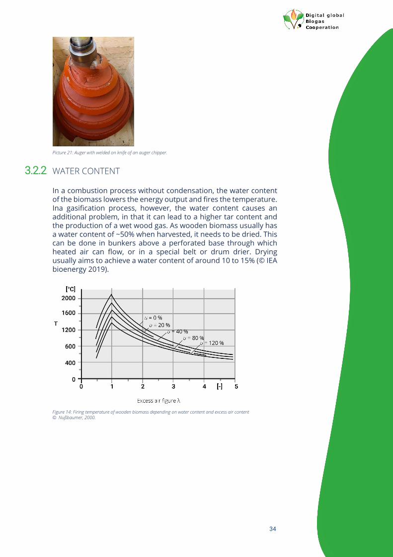
The need to heat up and vaporise water during the gasification or combustion process creates an energy demand. In a process without condensation, the energy demand for the vaporisation of water is significant, at 2,26 MJ kgH2O
-1, while the heating up of water requires only 0.004 MJ kgH2O
-1 °C-1.
Wood densityVariations in the densities of the different wood species and the associated differences in energy content per kgDM should also be taken into consideration. Further disparities between types and species of wood arise due to growth conditions such as climate, weather, height above sea level, availability of nutrients, water and sunlight availability etc.
Graph 2: Heating value inferior of wooden biomass related to water content and moisture content, © Eltrop, 2014.
32
FEEDSTOCK REQUIREMENTS FOR USE IN GASIFIERS
Many problems in gasification occur because the feedstock is not adjusted to meet the particular requirements of the gasification process. Feedstock specifications vary, depending on the type of gasifier.
FEEDSTOCK SIZE AND FINE DUST
Fixed bed gasifiers have relatively exacting requirements regarding feedstock size and especially concerning the share of fine dust that may be included. This is because, within fixed bed gasifiers, the gasification medium and the wood gas produced need to flow through the feedstock. Different flow resistances within the wood bed may cause dead zones where no gasification takes place or tar etc. is formed without being further broken down. Therefore, almost all fixed bed gasification installations run a sieving device for fine dust. This same piece of equipment also usually separates out oversized particles (mainly oversized in length). A downdraft
Table 9: Density of different wood species © Kaltschmitt, 2016.
Table 10: Requirement on biomass dependent on gasifier technique © IEA bioenergy, 2019.
3.2
3.2.1

33
This project has received funding from the European Union´s Horizon 2020 research and innovation programme under grant agreement N° 857804. The sole responsibility for the content of this document lies with the authors. It does not necessarily reflect the opinion of the EU.
fixed bed gasifier requires the use of chunkier wooden biomass – something that is sometimes achieved via a special woodchipper, which employs an auger chipping device instead of a drum chipping device.
Picture 17: Different piles of chipped wood before sieving.
Picture 20: Drum sieve.
Picture 19: Sieved wood chips.
Picture 18: Left: fine dust, right: oversized particles after sieving.
34
WATER CONTENT
In a combustion process without condensation, the water content of the biomass lowers the energy output and fires the temperature. Ina gasification process, however, the water content causes an additional problem, in that it can lead to a higher tar content and the production of a wet wood gas. As wooden biomass usually has a water content of ~50% when harvested, it needs to be dried. This can be done in bunkers above a perforated base through which heated air can flow, or in a special belt or drum drier. Drying usually aims to achieve a water content of around 10 to 15% (© IEA bioenergy 2019).
Picture 21: Auger with welded on knife of an auger chipper.
Figure 14: Firing temperature of wooden biomass depending on water content and excess air content © Nußbaumer, 2000.
3.2.2

35
Picture 23: Belt dryer.
Picture 22: Left: grate dryer with sliding floor and air pipes, right: perforated floor.

36
PRODUCTS OF GASIFICATION 4The main aim of the gasification of wooden biomass is to produce a calorific gas: to date, this has chiefly been used as a fuel for CHP, but it could also be upgraded to produce renewable methane and thus become a natural gas substitute. The secondary product of gasification is the residual ash. Depending on the gasification process, the latter may include organic carbon or may be limited to inert substances from the feedstock, such as nutrients, trace elements and any impurities.
WOOD GAS
There are many different possible compositions of wood gas.The numerous factors which have an influence on the make up of the generated wood gas include:
• Feedstock – size, moisture content, chemical composition of wooden biomass
• Catalytic additives• Gasifier type• Gasification temperature• Gasification medium – air, oxygen, vapour...• Pressure within the gasifier• Retention time within the reactive zone
The kind of gasification medium –whether ambient air, oxygen, vapour or CO2– influences the composition of the wood gas mainly in terms of the atmospheric nitrogen content and the hydrogen content. Air as a gasification medium produces a wood gas with a relatively high share of atmospheric nitrogen. Overall, wood gas is usually a gas with a Low Calorific Value (LCV). By changing the gasification medium to oxygen or vapour, the hydrogen content and the energy content can be significantly raised. Some gasifiers use different gasification media at different stages of the process,for example injecting oxygen or vapour in the first stage to produce a wood gas with no atmospheric nitrogen in it, but using ambient air in the second process step to fully oxidise the remaining carbon and produce the heat required to maintain the endothermic first process step. The exhaust gas of the second process step then contains a high levels of CO2 and athmospheric nitrogen.
4.1

37
Depending on the intended use of the wood gas produced, manufacterers can steer the wood gas composition to some extent in the appropriate direction. The main components delivering the energy content are carbon monoxide, hydrogen and methane, while carbon dioxide, vapor and atmospheric nitrogen are the principal inert components in the gas composition.
Table 11: General influence of gasification medium to energy, hydrogen and atmospheric nitrogen content of wood gas © Eltrop, 2014.
Table 12: Typical composition and energy content of dry wood gas depending on gasification medium, values in column = average © Kaltschmitt, 2016; FNR, 2014; Nilsson, 2011.
Table 13: Typical ingredients of wood gas divided in components including energy content and without © Kalt-sch-mitt, 2016.

38
The choice of feedstock also plays an important role in determining the make-up of the wood gas. In order to evaluate the performance of different feedstock streams within gasification, the GoBiGas plant in Gothenburg did some trials with different biomass feedstocks while keeping other criteria as constant as possible. The plant used was a double fluidised bed gasifier.
One important criterion is to produce a relatively clean gas, which does not require too intensive a pretreatment before being used in a CHP. Some feedstocks, such as straw, can be a source of HCL and S, both of which can cause corrosion; choosing the right feedstock is therefore very important. Excessive fine dust and tar content in the gas produced causes major problems and in the worst cases can can completely impede any further use of the gas. Producing a wood gas with low fine dust and tar content is therefore key. This can be achieved by ensuring that the water content and fine dust content of the feedstock are low, by avoidingdead zones in fixed bed gasifiers, and by including a reduction process zone in the gasification process.
Alongside other factors, the choice of technology also influences the particle and tar content of the wood gas produced, and therefore also affects the further cleaning steps that will be required.
Table 14: Composition of wood gas depending on feedstock at the GoBiGas plant in Sweden © Hrbek, Larsson 2017.
Figure 15: Typical concentrations of contaminants within wood gas © Aranda Almansa, 2019.

39
A combination of gas cleaning devices, however, should enable the wood gas to be successfully used in CHP plants. The manufacturers of these cleaning devices all have their own specifications in terms of fine dust, tar and other gas impurities.
In order to achieve an application-friendly gas, the wood gas is usually pre-treated before being cleaned in several process steps, such as
• Cyclone separator• Hot gas filter• Cooler• Scrubber
The equipment that can be used for these steps and its technical set up differ substantially between manufacturers. Cleaning should also ensure that pipes, valves and other components are not clogged by tar, dust or condensed water. If the plant is running constantly at peak load, blockages of this sort are unlikely to pose a problem, but after a period of standstill, pipes clogged with tar etc. can be a major issue.
Particles will be usually separated out with a cyclone separator, a hot gas filter, an electrostatic air filter or a scrubber. An electrostatic filter or a scrubber will also remove most of the tar: the advantage of these two devices and in particular the electrostatic filter is the potential to remove both particles and tar with one piece of equipment.
Table 15: Usual particle and tar content of raw wood gas depending on gasification type © Kaltschmitt, 2016.
Table 16: Usual requirement of internal combustion engines running on wood gas © Eltrop, 2014.

40
This project has received funding from the European Union´s Horizon 2020 research and innovation programme under grant agreement N° 857804. The sole responsibility for the content of this document lies with the authors. It does not necessarily reflect the opinion of the EU.
Table 17: Performance of different types of gas cleaning techniques © Kaltschmitt 2016, Eltrop 2014.
Picture 24: From left to right: cyclone, single cartridge of a cartridge filter, cartridge filter with automatic cleaning device, baghouse filter.

41
ASH AND/OR CHARCOAL
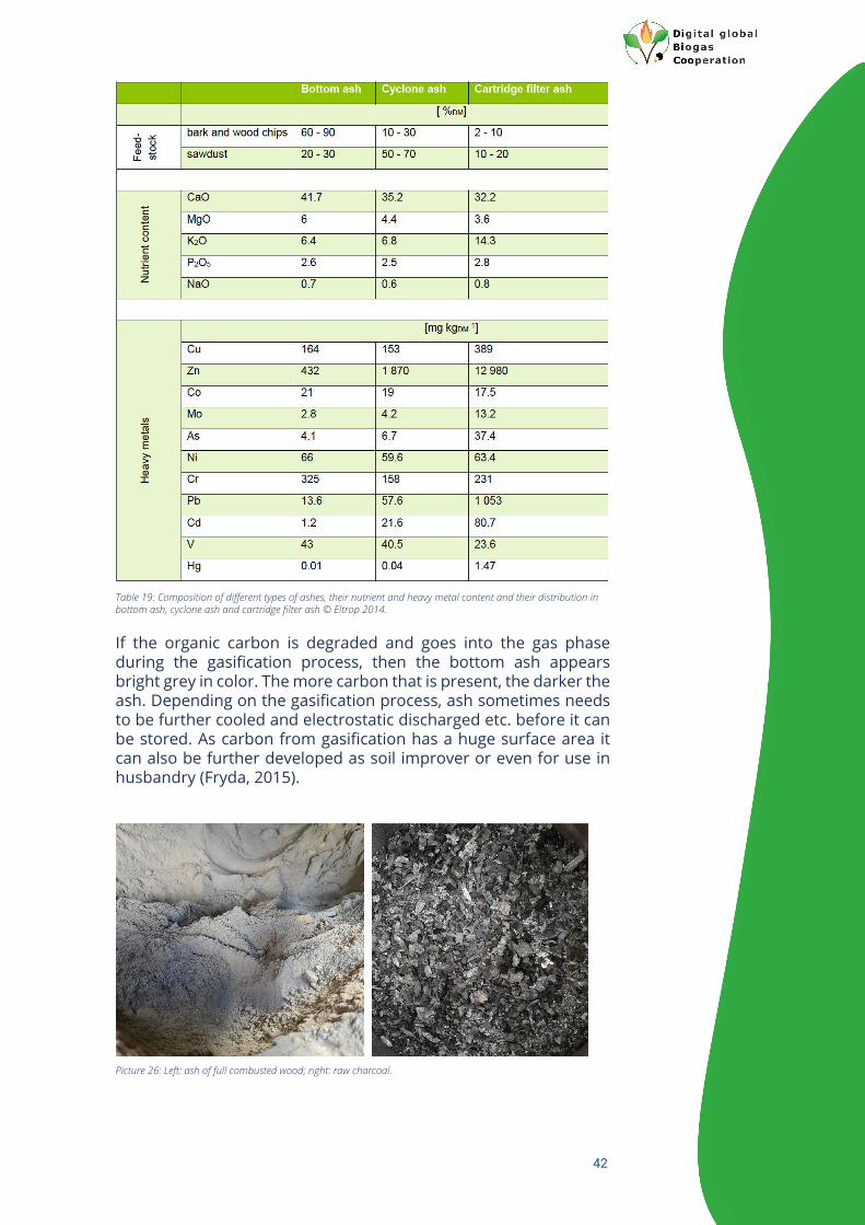
Depending on the gasification process and how it is managed, the ash will principally contain nutrients and trace elements, in some cases accompanied by impurities and heavy metals. It can also contain a certain amount of un-combusted carbon, however, which can be used to produce soil improver. The amount of ash generated depends on the feedstock. Wood generates only around 0.5%DM ash, while bark may produce 5 to 8%DM ash and straw even more, at around 10% (© Meyer, 2009). The types of ash can be divided up into bottom ash, cyclone ash and ash from the electrostatic or cartridge filter. Some levels of heavy metals will usually be found in the latter two types, whereas the bottom ash is usually not polluted. Depending on the recycling rate of the bed material, ash from fluidised bed gasifiers can also contain bed material. The heavy metal content in the ash differs depending on the source (the type of feedstock and whether treated or untreated), geological background and regional air pollution.
Picture 25: CHP unit to produce combined heat and power from wood gas.
Table 18: Composition of different feedstock and received ashes after treatment in large scale gasifier © Fryda, 2015.
4.2
42
If the organic carbon is degraded and goes into the gas phase during the gasification process, then the bottom ash appears bright grey in color. The more carbon that is present, the darker the ash. Depending on the gasification process, ash sometimes needs to be further cooled and electrostatic discharged etc. before it can be stored. As carbon from gasification has a huge surface area it can also be further developed as soil improver or even for use in husbandry (Fryda, 2015).
Table 19: Composition of different types of ashes, their nutrient and heavy metal content and their distribution in bottom ash, cyclone ash and cartridge filter ash © Eltrop 2014.
Picture 26: Left: ash of full combusted wood; right: raw charcoal.

43
This project has received funding from the European Union´s Horizon 2020 research and innovation programme under grant agreement N° 857804. The sole responsibility for the content of this document lies with the authors. It does not necessarily reflect the opinion of the EU.
Picture 27: From left to right: ash transporting device with double security valve, humidification device avoiding dust and self-ignition, humidified ash, hot dry ash.
Picture 28: Untreated charcoal, charcoal can with labelling, filling station for charcoal into big bags.

44
MCR: MEASUREMENT, CONTROL AND REGULATION TECHNIQUES AND SAFETY EQUIPMENT
5Most gasification plants are constructed and built by a general contractor. These companies deliver the whole plant, covering the processes from feedstock drying and the necessary feedstock pretreatment, through the gasification itself and up to and including the treatment of the wood gas produced. One component, which is integrated with all stages of the gasification process, is the MCR (measurement, control and regulation) technology. The MCR unit collates data from each part of the plant, records the information, analyses it and uses it to optimise the gasification process and ensure that it is safe and stable. Depending on the gasification type and the MCR control strategy, the following data might be collected (alongside the manually checked and recorded data):
• Pressure • Temperature• Filling levels• Different gas levels – Oxygen, Hydrogen, Methane, Carbon
Dioxide, Carbon Monoxide• Optical barrier• Position of valves and sliders etc.• Energy produced
In order to guarantee that none of the generated gas flows back into the process, the pressure is usually monitored from the feedstock conveying system right up to the use of the wood gas within the CHP. Temperature sensors are mainly used in the gasification process and gas cooling devices but can also be used as safety devices. Additionally, by measuring the temperature in the different sections of the gasifier, the process can be monitored and controlled.
Picture 29: Sensor to check the filling level and to secure the feedstock conveying system.

45
This project has received funding from the European Union´s Horizon 2020 research and innovation programme under grant agreement N° 857804. The sole responsibility for the content of this document lies with the authors. It does not necessarily reflect the opinion of the EU.
Picture 30: Left: delinking of ambient air to the gasifier via water barrier, right: torch.
Picture 31: Sensor to check the gasification process.
Picture 32: Visualisation of the measurement, control and regulation unit.

46
This project has received funding from the European Union´s Horizon 2020 research and innovation programme under grant agreement N° 857804. The sole responsibility for the content of this document lies with the authors. It does not necessarily reflect the opinion of the EU.
Picture 33: Hazard Plan.
Picture 34: Fix installed safety devices (gas and flame detection).
Picture 35: Handheld safety device to detect different types of gases (toxic, explosive).

47
Ablinger, D., & Aschl, T. (2014). Gaserzeugung aus Holz. Wels: FH OOE.
Anerud, E., Krigstin, S., Routa , J., Brännström, H., Arshadi, M., Helmeste, C., Egnell, G. (2019). Dry matter losses during biomass storage. Paris: IEA.
Aranda Almansa, G., Mourao Vilela, C., & Vregdenhil, B. (2018). Gas analysis in gasification of biomass and waste, doc 1. Paris: IEA bioenergy.
Aranda Almansa, G., Mourao Vilela, C., & Vreugdenhi, B. (2018). Gas analysis in gasification of biomass and waste report I. Paris: IEA bioenergy.
Aranda Almansa, G., Mourao Vilela, C., & Vreugdenhil, B. (2018). Gas analysis in gasification of biomass and waste report II. Paris: IEA bioenergy.
Aranda Almansa, G., Mourao, V. C., & Vreugdenhil, B. (2018). Gas analysis in gasification of biomass and waste, doc 2. Paris: IEA bioenergy.
Baumgartner, H., & Lasselsberger, L. (2020). Factsheet saubere Verbrennung. Vienna: Wärme aus holz.
Beckmann, M., & Ncube, S. (2007). Charakterisierung von Ersatzbrennstoffen hinsichtlich brenntechnischer Eigenschaften. Witzenhausen: Witzenhausen.
Bioenergy, I. (2014). Producer Gas as engine fuel. Paris: IEA.
Bioenergy, I. (2014). Selection of Gasification technology. Paris: IEA.
Böhning, D., & Beckmann, M. (2009). Dezentrale Biomassevergasung - Teerabbau durch primäre und sekundäre Maßnahmen. Neuruppin: Erneuerbare Energien.
Bräkow, d. (2018). Analytic, Checks, Tests and Examples of Coal containing residues and by products out of small scale thermo chemical wood gasification CHP plants. Berlin: FEE.
Eltrop, L., Poboss, N., Scheffknecht, G., Hartmann, H., Härdtlein, M., Jenssen, T., Özdemir, D. (2014). Leitfaden Feste Biomasse. Gülzow: FNR.
European Commission. (2020). Statistical pocketbook 2020 - Energy. Luxembourg: European Commission.
Fryda, L., & Visser, R. (2015). Biochar for Soil Improvement. Petten: ECN.
Held, J. (2018). System study of small scale thermochemical conversion of lignocellulosic feedstock to biomethane. Lund: Renewable Energy Technology International AB.
Held, J., & Olofsson, J. (2018). System study of small scale thermochemical conversion of lignocellulosic feedstock to biomethane. Lund: Renewable Energy Technology International AB.
Hofbauer, H., Kaltschmitt, M., & Wilk, V. (2016). Thermo chemische Umwandlungsprozesse. Berlin: Springer.
REFERENCES

48
Hrbek, J. (2018). Thermal gasification based hybrid systems. Vienna: IEA bioenergy.
Hrbek, J. (2019). Status report on thermal gasification of biomass and waste. Vienna: IEA bioenergy.
Hrbek, J., & Vreugdenhil, B. (2020). The past, present and future of gasification. online semiar: IEA task 33.
Kaltschmitt, M., & Hartmann, H. (2008). Energie aus Biomasse. Berlin: Springer.
Lamers, F., Cremers, M., Matschegg, D., & Schmidl, C. (2018). Options for increased use of ash from biomass combustion and co firing. Paris: IEA.
Lasselsberger, L. (2007). Energie aus fester pflanzlicher Biomasse. wien: BMLRT.
Liptay, P., & Pfemeter, C. (2019). Holzgas: Strom, Kraftstoff, Erdgasersatz. Vienna: Biomasseverband.
Meyer, B., Krzack, S., Schreiner, M., & Boblenz, K. (2010). Aschen der Biomassevergasung. Freiberg: Bergakademie Freiberg.
Nußbaumer, T. (2000). Holzenergie. Zürich: ETH.
Nwokolo, N., Mampheli, S., & Makaka, G. (21. 12 2016). Analytical and thermal evaluation of carbon particles recovered at the cyclone of a downdraft gasfication. Sustainability.
Obernberger, I., & Thek, G. (2008). Combustion and Gasification of solid biomass for heat and power production . Vilamoura: 8th European Conference on Industrial Furnaces and Boilers.
Rothermel, N. (2017). Erzeugung eines wasserstoffreichen Produktgases aus Biomasse mittels Wasserdampfvergasung und anschließender CO2 Abscheidung. Stuttgart.
Schmidl, C., Aigenbauer, S., Moser , W., & Lasselsberger, L. (2020). Neue Öfen 2020. Wien: FFG.
Schwarz, M., & Strasser, C. (2019). Factsheet Staubemissionen. Vienna: BEST.
Sikarwar, V., Zhao, M., Clough, P., & Fennell, P. (30. March 2016). An overview of advances in biomass gasification. Energy & Environmental Science.
Stapf, D., Ceceri, G., Johannson, I., & Whitty, K. (2018). Biomass pretratment for bioenergy: case study 3. Paris: IEA.
Thiffault, E., Sokhansanj, S., Ebadian, M., Rezaei, H., Yazdanpanah, F., Asikainen, A., & Routa, J. (2018). Biomass pretreatment for bioenergy: case study 2. Paris: IEA.
Wild, M., & Visser, L. (2018). Biomass pretreatment for bioenergy: case study 1. Paris: IEA.

49
This project has received funding from the European Union´s Horizon 2020 research and innovation programme under grant agreement N° 857804. The sole responsibility for the content of this document lies with the authors. It does not necessarily reflect the opinion of the EU.
THE DiBiCoo CONSORTIUM

50
This project has received funding from the European Union´s Horizon 2020 research and innovation programme under grant agreement N° 857804. The sole responsibility for the content of this document lies with the authors. It does not necessarily reflect the opinion of the EU.
Author(s) Franz Kirchmeyr, Austrian Compost & Biogas Association, Vienna, Austria.
Review Frank Hofmann (FVB), Mieke Dekorte (EBA), Angela Sainz (EBA), Dr. Wondwossen (ICEADDIS),Ann-Kathrin van Laere (GIZ), Dr. Johannes Anhorn (GIZ), Dominik Rutz (WIP), FelixColmorgen (WIP).
Photo credits/sources The author(s) if not otherwise stated (Name/Partner Acronym).
Disclaimer Neither the author(s), or GIZ, nor any other consortium member will accept any liability at anytime for any kind of damage or loss that might occur to anybody from referring to this document.In addition, neither the European Commission nor the Agencies (or any person actingon their behalf) can be held responsible for the use made of the information provided in thisdocument.
URL links Responsibility for the content of external websites linked in this publication always lies withtheir respective publishers. The author(s) expressly dissociates themselves from such content.
Vienna, 2021
Dr. Johannes Anhorn Deutsche Gesellschaft für Internationale Zusammenarbeit (GIZ) GmbH
www.giz.de
Wielinger Straße 52 82340 Feldafing, Germany
Project website: www.dibicoo.org
PROJECT COORDINATOR CONTACT

Dr. Johannes Anhorn Deutsche Gesellschaft für Internationale Zusammenarbeit (GIZ) GmbH
www.giz.de
Wielinger Straße 52 82340 Feldafing, Germany
Project website: www.dibicoo.org
PROJECT COORDINATOR CONTACT
About DiBiCoo
We facilitate collaboration between European biogas industries & stakeholders from emerging and developing markets through the development and application of innovative digital and non-digital support tools, knowledge transfer and capacity building.