Embed Size (px)
Citation preview
Easy
Safe
Light
Smart
Quick
High performance, multi function and easy use, all advanced.
2011/5AC ServoMINAS A5 series Catalog
2011 / 5
Cautions for Proper Use
Repa i r
URL
Consult to the dealer from whom you have purchased this product for details of repair work. When the product is incorporated to the machine you have purchased, consult to the machine manufacturer or its dealer.
Electric data of this product (Instruction Manual, CAD data) can be download from the following web site; <http://industrial.panasonic.com/ww/i_e/25000/motor_fa_e/motor_fa_e.html
Contact to :
1-1 Morofuku 7-chome, Daito, Osaka 574-0044, JapanTel : +81-72-871-1212Fax: +81-72-870-3151
The contents of this catalog apply to the products as of May 1, 2011.
• Practical considerations for exporting the product or assembly containing the product When the end user of the product or end use of the product is associated with military affair or weapon, its export may be
controlled by the Foreign Exchange and Foreign Trade Control Law. Complete review of the product to be exported and export formalities should be practiced.
• This product is intended to be used with a general industrial product, but not designed or manufactured to be used in a machine or system that may cause personal death when it is failed.
• Installation, wiring, operation, maintenance, etc., of the equipment should be done by qualified and experienced personnel. • Apply adequate tightening torque to the product mounting screw by taking into consideration strength of the screw and the
characteristics of material to which the product is installed. Overtightening can damage the screw and/or material; undertightening can result in loosening.
Example) Steel screw (M5) into steel section: 2.7-3.3 N·m. • Install a safety equipments or apparatus in your application, when a serious accident or loss of property is expected due to the
failure of this product. • Consult us if the application of this product is under such special conditions and environments as nuclear energy control,
aerospace, transportation, medical equipment, various safety equipments or equipments which require a lesser air contamination.
• We have been making the best effort to ensure the highest quality of the products, however, application of exceptionally larger external noise disturbance and static electricity, or failure in input power, wiring and components may result in unexpected action. It is highly recommended that you make a fail-safe design and secure the safety in the operative range.
• If the motor shaft is not electrically grounded, it may cause an electrolytic corrosion to the bearing, depending on the condition of the machine and its mounting environment, and may result in the bearing noise. Checking and verification by customer is required.
• Failure of this product depending on its content, may generate smoke of about one cigarette. Take this into consideration when the application of the machine is clean room related.
• Please be careful when using in an environment with high concentrations of sulfur or sulfric gases, as sulfuration can lead to disconnection from the chip resistor or a poor contact connection.
• Take care to avoid inputting a supply voltage which significantly exceeds the rated range to the power supply of this product. Failure to heed this caution may result in damage to the internal parts, causing smoking and/or a fire and other trouble.
• The user is responsible for matching between machine and components in terms of configuration, dimensions, life expectancy, characteristics, when installing the machine or changing specification of the machine. The user is also responsible for complying with applicable laws and regulations.
• The product will not be guaranteed when it is used outside its specification limits. • Parts are subject to minor change to improve performance. • Read and observe the instruction manual without fail for proper usage of the products.
• Printed colors may be slightly different from the actual products.• Specifications and design of the products are subject to change without notice for the product improvement.
AC
Servo
<MIN
AS A5 Series>
<11.05 S >
ISO14001 Certificate division CERTIFICATE OF APPROVAL ISO14001
ISO9001 Certificate division CERTIFICATE OF APPROVAL ISO9001
Phone: 800.894.0412 - Fax: 888.723.4773 - Web: www.ctiautomation.net - Email: [email protected]
1
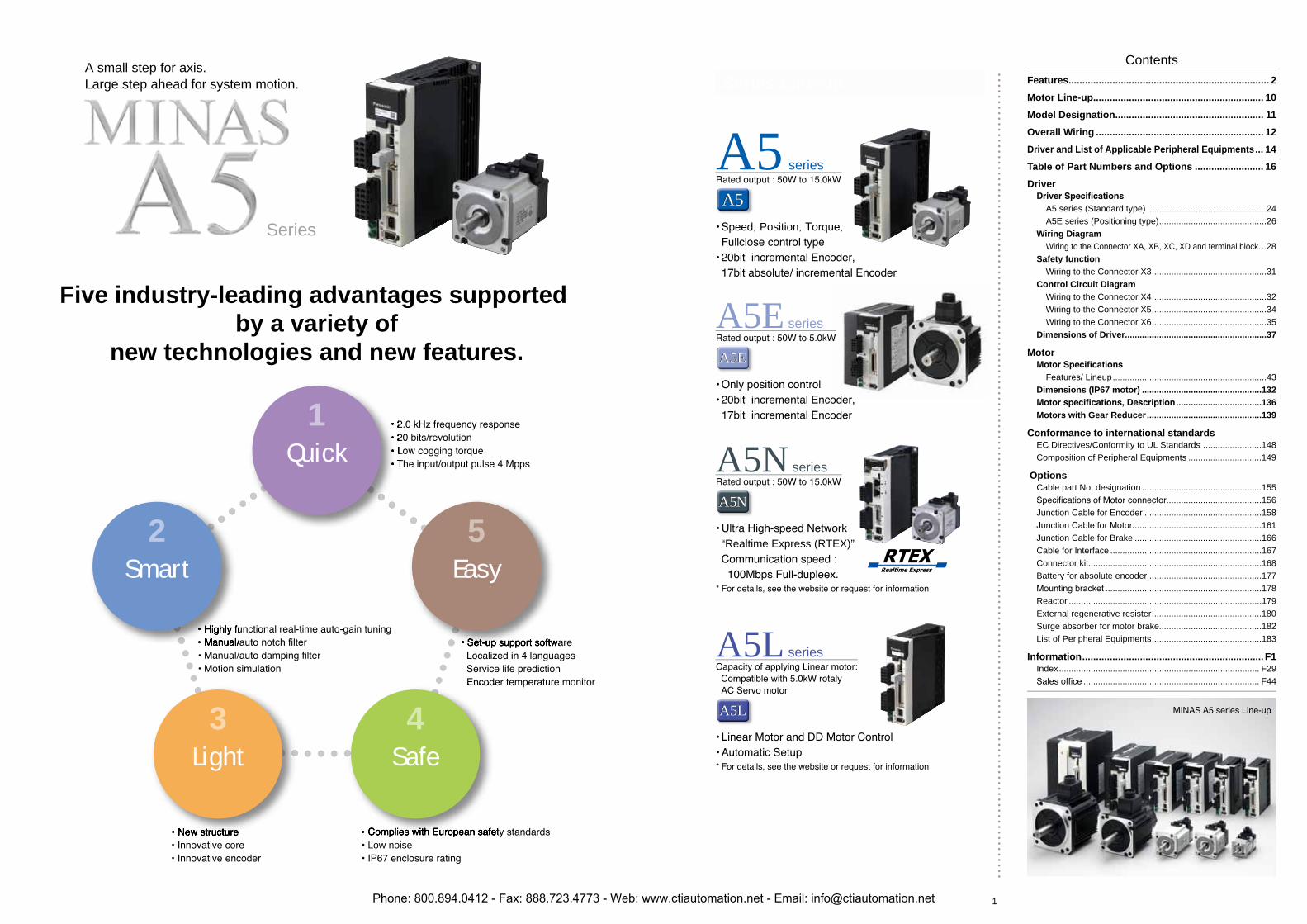
A small step for axis.Large step ahead for system motion.
Five industry-leading advantages supported by a variety of
new technologies and new features.
Series
Low noise
Quick1
Smart2
Light3
Safe4
Easy5
Series Line-up
A5 series
, Position, ,
A5E series
A5EA5E
A5N series
“Realtime Express (RTEX)”
A5LA5L
A5NA5N
A5L series
A5A5
ContentsFeatures......................................................................... 2
Motor Line-up.............................................................. 10
Model Designation...................................................... 11
Overall Wiring ............................................................. 12
Driver and List of Applicable Peripheral Equipments... 14
Table of Part Numbers and Options ......................... 16
Driver
A5 series (Standard type) .................................................24 A5E series (Positioning type)............................................26
Wiring Diagram Wiring to the Connector XA, XB, XC, XD and terminal block...28
Safety function Wiring to the Connector X3...............................................31
Control Circuit Diagram Wiring to the Connector X4...............................................32 Wiring to the Connector X5...............................................34 Wiring to the Connector X6...............................................35
Dimensions of Driver..........................................................37
Motor
Features/ Lineup...............................................................43Dimensions (IP67 motor) .................................................132
...................................136Motors with Gear Reducer...............................................139
Conformance to international standardsEC Directives/Conformity to UL Standards ........................148Composition of Peripheral Equipments ..............................149
OptionsCable part No. designation .................................................155
.......................................156Junction Cable for Encoder ................................................158
.....................................................161Junction Cable for Brake ....................................................166Cable for Interface ..............................................................167Connector kit.......................................................................168Battery for absolute encoder...............................................177
................................................................178Reactor ...............................................................................179External regenerative resister.............................................180Surge absorber for motor brake..........................................182List of Peripheral Equipments.............................................183
Information..................................................................F1Index.................................................................................. F29
........................................................................ F44
Phone: 800.894.0412 - Fax: 888.723.4773 - Web: www.ctiautomation.net - Email: [email protected]
2 3
Features
Example application Semiconductor production equipment, packaging, etc.
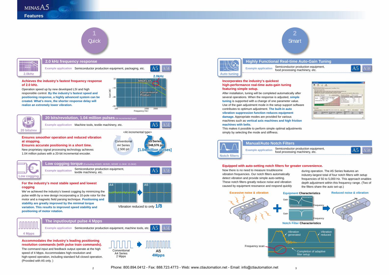
2.0 kHz frequency response
Achieves the industry’s fastest frequency response of 2.0 kHz.Operation speed up by new developed LSI and high responsible control. By the industry’s fastest speed and positioning response, a highly advanced system can be created. What’s more, the shorter response delay will realize an extremely lower vibration.
Incorporates the industry’s quickest high-performance real-time auto-gain tuning featuring simple setup.After installation, tuning will be completed automatically after several operations. When the response is adjusted, simpletuning is supported with a change of one parameter value. Use of the gain adjustment mode in the setup support software contributes to optimum adjustment. The built-in auto vibration suppression function reduces equipment damage. Appropriate modes are provided for various machines such as vertical axis machines and high friction machines with belts.This makes it possible to perform simple optimal adjustments simply by selecting the mode and stiffness.
Example application
Highly Functional Real-time Auto-Gain Tuning
Example application
Manual/Auto Notch Filters
Ensures smoother operation and reduced vibration at stopping.Ensures accurate positioning in a short time.New proprietary signal processing technology achieves 1.04 million pulses with a 20-bit incremental encoder.
For the industry’s most stable speed and lowest coggingWe’ve achieved the industry’s lowest cogging by minimizing the pulse width by a new design incorporating a 10-pole rotor for the motor and a magnetic field parsing technique. Positioning and stability are greatly improved by the minimal torque variation. This results to improved speed stability and positioning of motor rotation.
Example application Machine tools, textile machinery, etc.
ConventionalA4 Series2,500 p/r
ConventionalA4 Series2 Mpps
A5 Series1,048,576 p/r
[1.04 million pulses]
A5 Series1,048,576 p/r
[1.04 million pulses]
A54Mpps
Example application
Accommodates the industry’s leading positioning resolution commands (with pulse train commands).The command input and feedback output operate at the high speed of 4 Mpps. Accommodates high-resolution and high-speed operation, including standard full closed operation. (Provided with A5 only. )
Example application Semiconductor production equipment, machine tools, etc.
Vibration reduced to only 1/8
A4 A5
Notch Filter Characteristics
Equipment CharacteristicsExcessive noise & vibration Reduced noise & vibration
Gain
Gain
Frequency
Frequency
Resonance
Antiresonance
Frequency scan
10
Frequency(Hz)G
ain(
dB)
100 20001000
MINAS A5
ConventionalProductConventionalProduct
MINAS A5
Vibrationreduced
Vibrationgenerated
Completion of adaptivefilter setup
2.0kHz
Low cogging torque (Excluding MSMD, MHMD, MDME 11.0kW. 15.0kW)
20 bits/revolution, 1.04 million pulses (At incremental type)
The input/output pulse 4 Mpps
A4A5
Equipped with auto-setting notch filters for greater convenience.Now there is no need to measure troublesome vibration frequencies. Our notch filters automatically detect vibration and provide simple auto-setting. These notch filters greatly reduce noise and vibration caused by equipment resonance and respond quickly
A5
ConventionalProduct
during operation. The A5 Series features an industry-largest total of four notch filters with setup frequencies of 50 to 5,000 Hz. This approach enables depth adjustment within this frequency range. (Two of the filters share the auto set-up.)
Quick1
Smart2
4 Mpps
Low cogging
20 bits/rev
2.0kHz Auto tuning
Notch filters
A5EA5EA5A5
A5EA5E
A5EA5E
A5EA5E
A5A5
A5A5
A5A5
Semiconductor production equipment, textile machinery, etc.
A5EA5EA5A5
A5EA5EA5A5Semiconductor production equipment, food processing machinery, etc.
Semiconductor production equipment, food processing machinery, etc.
<At incremental type>
Phone: 800.894.0412 - Fax: 888.723.4773 - Web: www.ctiautomation.net - Email: [email protected]
4 5
Frequency MHz
dB
Features
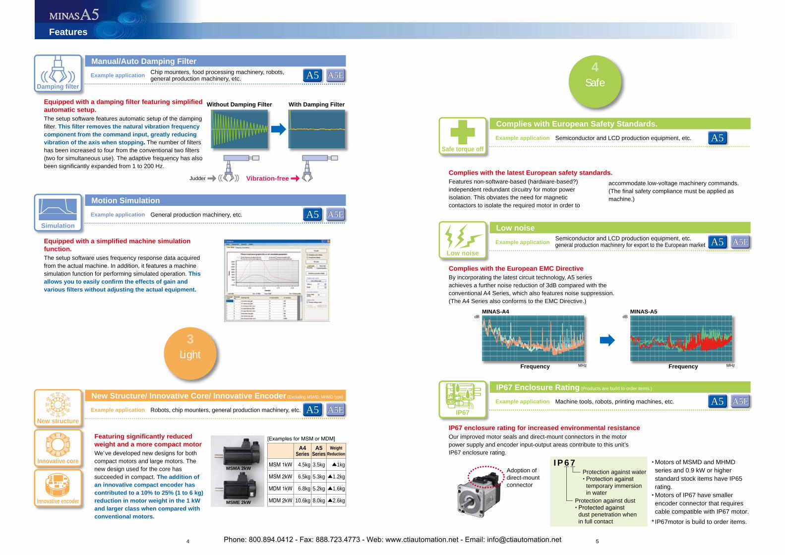
Without Damping Filter With Damping Filter
Judder
Frequency MHz
dB
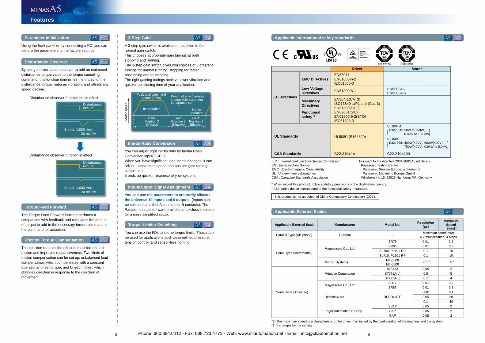
I P 6 7
Protection against dust
dust penetration when in full contact
Protection against water
temporary immersion in water
Adoption of direct-mountconnector
IP67 enclosure rating for increased environmental resistanceOur improved motor seals and direct-mount connectors in the motor power supply and encoder input-output areas contribute to this unit’sIP67 enclosure rating.
Vibration-freeComplies with the latest European safety standards.Features non-software-based (hardware-based?) independent redundant circuitry for motor power isolation. This obviates the need for magnetic contactors to isolate the required motor in order to
accommodate low-voltage machinery commands. (The final safety compliance must be applied as machine.)
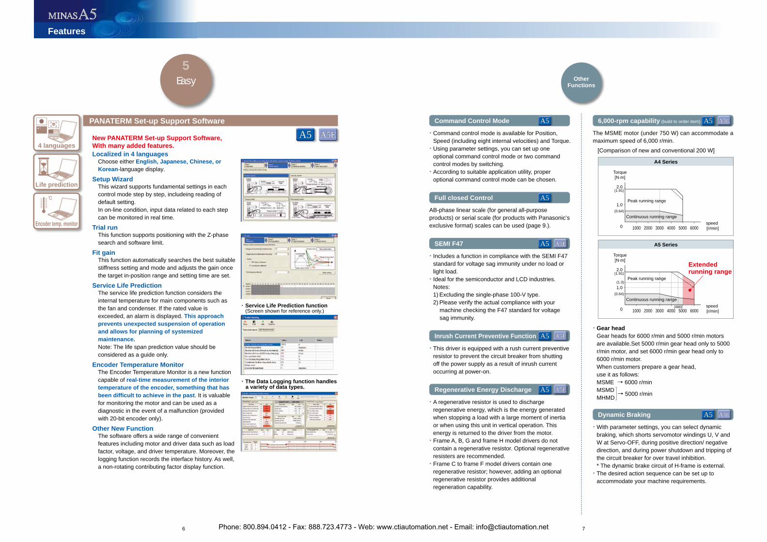
MINAS-A4 MINAS-A5
Light3
Safe4
Equipped with a damping filter featuring simplified automatic setup.The setup software features automatic setup of the damping filter. This filter removes the natural vibration frequency component from the command input, greatly reducing vibration of the axis when stopping. The number of filters has been increased to four from the conventional two filters (two for simultaneous use). The adaptive frequency has also been significantly expanded from 1 to 200 Hz.
Example application
Manual/Auto Damping FilterChip mounters, food processing machinery, robots, general production machinery, etc.
Complies with the European EMC DirectiveBy incorporating the latest circuit technology, A5 series achieves a further noise reduction of 3dB compared with the conventional A4 Series, which also features noise suppression. (The A4 Series also conforms to the EMC Directive.)
Example application
Low noiseSemiconductor and LCD production equipment, etc.general production machinery for export to the European marketEquipped with a simplified machine simulation
function.The setup software uses frequency response data acquired from the actual machine. In addition, it features a machine simulation function for performing simulated operation. Thisallows you to easily confirm the effects of gain and various filters without adjusting the actual equipment.
Example application
Motion Simulation
General production machinery, etc.
Example application
IP67 Enclosure Rating (Products are build to order items.)
Machine tools, robots, printing machines, etc.
Featuring significantly reduced weight and a more compact motorWe’ve developed new designs for both compact motors and large motors. The new design used for the core has succeeded in compact. The addition of an innovative compact encoder has contributed to a 10% to 25% (1 to 6 kg) reduction in motor weight in the 1 kW and larger class when compared with conventional motors.
Example application
New Structure/ Innovative Core/ Innovative Encoder (Excluding MSMD, MHMD type)
Robots, chip mounters, general production machinery, etc.
Example application
Complies with European Safety Standards.
Semiconductor and LCD production equipment, etc.
Safe torque off
Low noise
IP67
Damping filter
Simulation
New structure
Innovative core
Innovative encoder
A5EA5EA5A5
A5EA5EA5A5
A5EA5EA5A5
A5A5
A5EA5EA5A5
A5EA5EA5A5
Motors of MSMD and MHMD series and 0.9 kW or higher standard stock items have IP65 rating.Motors of IP67 have smaller encoder connector that requires cable compatible with IP67 motor.
* IP67motor is build to order items.
A4Series
A5Series
Weight Reduction
4.5kg 3.5kg ▲1kg
6.5kg 5.3kg ▲1.2kg
6.8kg 5.2kg ▲1.6kg
10.6kg 8.0kg ▲2.6kg
MSMA 2kW
MSME 2kW
Phone: 800.894.0412 - Fax: 888.723.4773 - Web: www.ctiautomation.net - Email: [email protected]
6 7
A5A5
A5EA5EA5A5
A5EA5EA5A5
A5EA5EA5A5
A5EA5EA5A5
Easy5
Features
℃
・ Service Life Prediction function (Screen shown for reference only.)
・ The Data Logging function handles a variety of data types.
New PANATERM Set-up Support Software, With many added features.Localized in 4 languages Choose either English, Japanese, Chinese, or
Korean-language display.Setup Wizard
This wizard supports fundamental settings in each control mode step by step, includeing reading of default setting.
In on-line condition, input data related to each step can be monitored in real time.
Trial runThis function supports positioning with the Z-phase search and software limit.
Fit gainThis function automatically searches the best suitable stiffness setting and mode and adjusts the gain once the target in-position range and setting time are set.
Service Life PredictionThe service life prediction function considers the internal temperature for main components such as the fan and condenser. If the rated value is exceeded, an alarm is displayed. This approach prevents unexpected suspension of operation and allows for planning of systemized maintenance.
Note: The life span prediction value should be considered as a guide only.
Encoder Temperature MonitorThe Encoder Temperature Monitor is a new function capable of real-time measurement of the interior temperature of the encoder, something that has been difficult to achieve in the past. It is valuable for monitoring the motor and can be used as a diagnostic in the event of a malfunction (provided with 20-bit encoder only).
Other New FunctionThe software offers a wide range of convenient features including motor and driver data such as load factor, voltage, and driver temperature. Moreover, the logging function records the interface history. As well, a non-rotating contributing factor display function.
PANATERM Set-up Support Software
4 languages
Life prediction
Encoder temp. monitor
Command Control Mode
• Command control mode is available for Position, Speed (including eight internal velocities) and Torque.• Using parameter settings, you can set up one
optional command control mode or two command control modes by switching.• According to suitable application utility, proper
optional command control mode can be chosen.
SEMI F47
• Includes a function in compliance with the SEMI F47 standard for voltage sag immunity under no load or light load.• Ideal for the semiconductor and LCD industries.
Notes:1) Excluding the single-phase 100-V type.2) Please verify the actual compliance with your
machine checking the F47 standard for voltage sag immunity.
A5EA5EA5A5Inrush Current Preventive Function
• This driver is equipped with a rush current preventive resistor to prevent the circuit breaker from shutting off the power supply as a result of inrush current occurring at power-on.
Full closed Control
AB-phase linear scale (for general all-purpose products) or serial scale (for products with Panasonic’sexclusive format) scales can be used (page 9.).
6,000-rpm capability (build to order item)
The MSME motor (under 750 W) can accommodate a maximum speed of 6,000 r/min. [Comparison of new and conventional 200 W]
OtherFunctions
(0.64)
(1.91)
Torque[N·m]
Peak running range
Continuous running rangespeed[r/min]
2.0
1.0
0 1000 2000 3000 4000 5000 6000
(0.64)
(1.91)
Torque[N·m]
Peak running range
Continuous running rangespeed[r/min]
2.0
(1.3)
(4600)
1.0
0 1000 2000 3000 4000 5000 6000
A4 Series
Extendedrunning range
A5 Series
A5EA5EA5A5
A5A5
Regenerative Energy Discharge
• A regenerative resistor is used to discharge regenerative energy, which is the energy generated when stopping a load with a large moment of inertia or when using this unit in vertical operation. This energy is returned to the driver from the motor.• Frame A, B, G and frame H model drivers do not
contain a regenerative resistor. Optional regenerative resisters are recommended.• Frame C to frame F model drivers contain one
regenerative resistor; however, adding an optional regenerative resistor provides additional regeneration capability.
Dynamic Braking
• With parameter settings, you can select dynamic braking, which shorts servomotor windings U, V and W at Servo-OFF, during positive direction/ negative direction, and during power shutdown and tripping of the circuit breaker for over travel inhibition.
* The dynamic brake circuit of H-frame is external.• The desired action sequence can be set up to
accommodate your machine requirements.
• Gear head Gear heads for 6000 r/min and 5000 r/min motors
are available.Set 5000 r/min gear head only to 5000 r/min motor, and set 6000 r/min gear head only to 6000 r/min motor.
When customers prepare a gear head, use it as follows: MSME → 6000 r/min MSMD → 5000 r/min MHMD
Phone: 800.894.0412 - Fax: 888.723.4773 - Web: www.ctiautomation.net - Email: [email protected]
8 9
A5EA5EA5A5 A5EA5EA5A5 A5EA5EA5A5
A5A5
A5EA5EA5A5
A5EA5EA5A5
A5EA5EA5A5
A5EA5EA5A5
A5EA5EA5A5
A5EA5EA5A5
Features
Disturbance observer function not in effect
Disturbance observer function in effect
* When export this product, follow statutory provisions of the destination country.* A5E series doesn't correspond to the functional safety *1 standard.
This product is not an object of China Compulsory Certification (CCC).
IEC : International Electrotechnical CommissionEN : Europaischen NormenEMC : Electromagnetic CompatibilityUL : Underwriters LaboratoriesCSA : Canadian Standards Association
Pursuant to the directive 2004/108/EC, article 9(2) Panasonic Testing Centre Panasonic Service Europe, a division of Panasonic Marketing Europe GmbH Winsbergring 15, 22525 Hamburg, F.R. Germany
Driver Motor
EMC DirectivesEN55011EN61000-6-2IEC61800-3
IEC61326-3-1
—
Low-VoltageDirectives EN61800-5-1 EN60034-1
EN60034-5
Functionalsafety *1
MachineryDirectives
EN954-1(CAT3)ISO13849-1(PL c,d) (Cat. 3)EN61508(SIL2)EN62061(SIL2)EN61800-5-2(STO)
—
UL508C (E164620)
UL1004-1 E327868: 50W to 750W,( 6.0kW to 15.0kW)UL1004 E327868: 400W(400V), 600W(400V),( 750W(400V), 0.9kW to 5.0kW)
C22.2 No.14 C22.2 No.100
EC Directives
CSA Standards
UL Standards
Disturbanceoccurs
Speed: 1,000 r/min20 ms/div
Disturbanceoccurs
Speed: 1,000 r/min20 ms/div
Mot
or s
peed
Gain:Position 2Effective
Gain:Position 3Effective
Period of effectivenesschangeable accordingto parameters.
Positional commandspeed [r/min]
Not inoperation
In operation
Gain:Position 1Effective
Parameter Initialization
Using the front panel or by connecting a PC, you can restore the parameters to the factory settings.
Disturbance Observer
By using a disturbance observer to add an estimated disturbance torque value to the torque canceling command, this function diminishes the impact of the disturbance torque, reduces vibration, and offsets any speed decline.
Torque Feed Forward
Applicable international safety standards
Applicable External ScalesThe Torque Feed Forward function performs a comparison with feedback and calculates the amount of torque to add to the necessary torque command in the command for actuation.
3-Step Gain
A 3-step gain switch is available in addition to the normal gain switch.This chooses appropriate gain tunings at both stopping and running.The 3-step gain switch gives you choices of 3 different tunings for normal running, stopping for faster positioning and at stopping. The right gaining tunings achieve lower vibration and quicker positioning time of your application.
Inertia Ratio Conversion
You can adjust right inertia ratio by Inertia Ratio Conversion input(J-SEL).When you have significant load inertia changes, it can adjust unbalanced speed and position gain turning combination.It ends up quicker response of your system.
Input/Output Signal Assignment
You can use the parameters to arbitrarily allocate the universal 10 inputs and 6 outputs. (Inputs can be selected as either A contacts or B contacts). The Panaterm setup software provides an exclusive screen for a more simplified setup.
Torque Limiter Switching
You can use the I/Os to set up torque limits. These can be used for applications such as simplified pressure, tension control, and sensor-less homing.Friction Torque Compensation
This function reduces the effect of machine-related friction and improves responsiveness. Two kinds of friction compensation can be set up: unbalanced load compensation, which compensates with a constant operational offset torque; and kinetic friction, which changes direction in response to the direction of movement.
(A5 series) (A5E series)
Applicable External Scale Manufacturer Model No.Resolution Maximum
Speed (m/s)*2
Parallel Type (AB-phase) General —
Serial Type (Incremental)
SR75 0.01 3.3SR85 0.01 3.3
SL700, PL101-RP 0.1 10SL710, PL101-RP 0.1 10
0.1*3 5*3
Serial Type (Absolute)
AT573A 0.05 2ST771A(L) 0.5 5ST773A(L) 0.1 4
SR77 0.01 3.3SR87 0.01 3.3
Renishaw plc RESOLUTE0.001 0.40.05 200.1 40
Fagor Automation S.CoopSVAP 0.05 2SAP 0.05 2GAP 0.05 2
*3: It changes by the setting.
Phone: 800.894.0412 - Fax: 888.723.4773 - Web: www.ctiautomation.net - Email: [email protected]
10 11
Motor Line-upMotor Line-up Model Designation
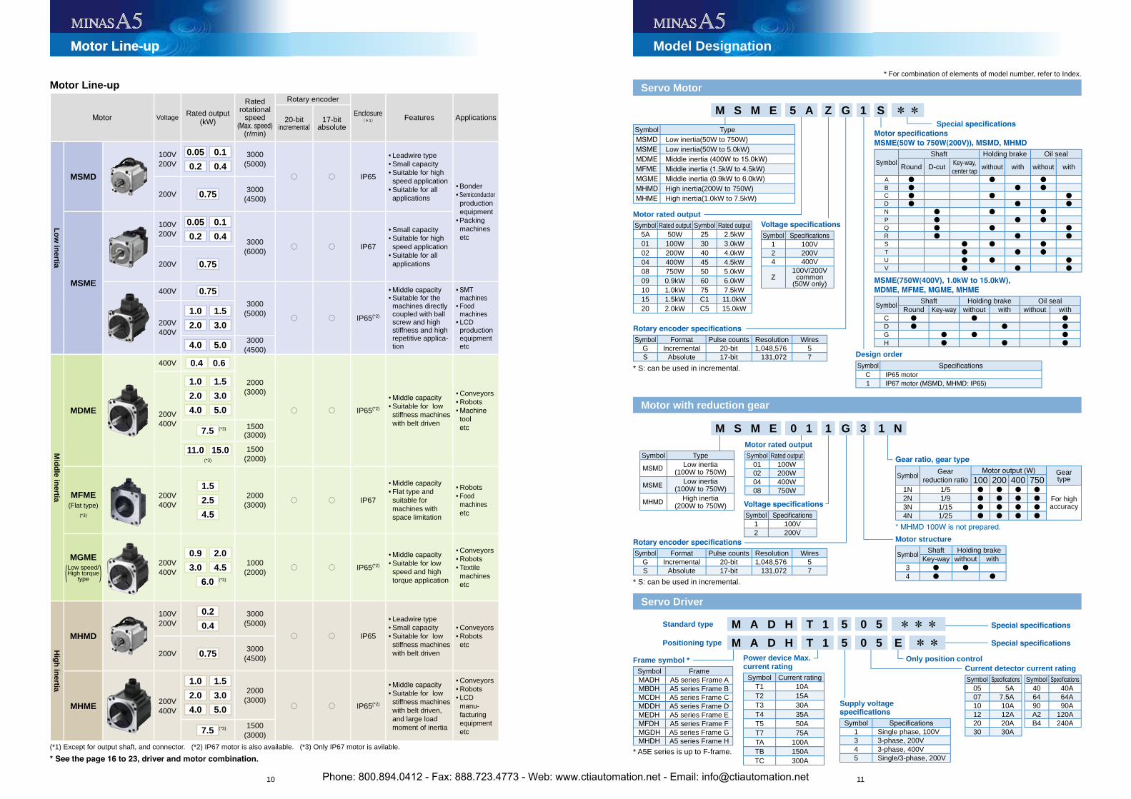
Motor Line-up
Voltage Rated output (kW)
Ratedrotational
speed
(r/min)
Rotary encoder
Enclosure(*1) Features Applications20-bit
incremental17-bit
absolute
Lo
w in
ertia
MSMD
100V200V
0.05 0.1
0.2 0.43000
(5000)○ ○ IP65
• Leadwire type• Small capacity• Suitable for high
speed application• Suitable for all
applications• Bonder• Semiconductor
productionequipment• Packing
machines etc
200V 0.75 3000(4500)
MSME
100V200V
0.05 0.1
0.2 0.4 3000(6000) ○ ○ IP67
• Small capacity• Suitable for high
speed application• Suitable for all
applications200V 0.75
400V 0.753000
(5000) ○ ○ IP65(*2)
• • Suitable for the
machines directly coupled with ball screw and high stiffness and high repetitive applica-tion
• machines• Food
machines• LCD
productionequipment
etc
200V400V
1.0 1.5
2.0 3.0
4.0 5.0 3000(4500)
Mid
dle in
ertia
MDME
400V 0.4 0.6
2000(3000)
○ ○ IP65(*2)
• • Suitable for low
stiffness machines with belt driven
• Conveyors• Robots•
tool etc
200V400V
1.0 1.5
2.0 3.0
4.0 5.0
7.5 (*3) 1500(3000)
11.0 15.0(*3)
1500(2000)
MFME(Flat type)
(*3)
200V400V
1.5
2.5
4.5
2000(3000) ○ ○ IP67
• • Flat type and
suitable for machines with space limitation
• Robots• Food
machines etc
MGMELow speed/High torque( type ) 200V
400V
0.9 2.0
3.0 4.5
6.0 (*3)
1000(2000) ○ ○ IP65(*2)
• • Suitable for low
speed and high torque application
• Conveyors• Robots• Textile
machines etc
Hig
h in
ertia
MHMD
100V200V
0.2
0.43000
(5000)○ ○ IP65
• Leadwire type• Small capacity• Suitable for low
stiffness machines with belt driven
• Conveyors• Robots etc
200V 0.75 3000(4500)
MHME200V400V
1.0 1.5
2.0 3.0
4.0 5.0
2000(3000)
○ ○ IP65(*2)
• • Suitable for low
stiffness machines with belt driven, and large load moment of inertia
• Conveyors• Robots• LCD
manu-facturingequipment
etc7.5 (*3) 1500(3000)
(*1) Except for output shaft, and connector. (*2) IP67 motor is also available. (*3) Only IP67 motor is avilable.
Servo Motor
Motor with reduction gear
Servo Driver
M S M E 5 A Z G 1 S **
Motor rated outputSymbol Rated output Symbol Rated output
5A 50W 25 2.5kW01 100W 30 3.0kW02 200W 40 4.0kW04 400W 45 4.5kW08 750W 50 5.0kW09 0.9kW 60 6.0kW10 1.0kW 75 7.5kW15 1.5kW C1 11.0kW20 2.0kW C5 15.0kW
Special
SymbolShaft Holding brake Oil seal
Round D-cut Key-way, center tap without with without with
A ● ● ●B ● ● ●C ● ● ●D ● ● ●N ● ● ●P ● ● ●Q ● ● ●R ● ● ●S ● ● ●T ● ● ●U ● ● ●V ● ● ●
Symbol Shaft Holding brake Oil sealRound Key-way without with without with
C ● ● ●D ● ● ●G ● ● ●H ● ● ●Symbol Format Pulse counts Resolution Wires
G Incremental 20-bit 1,048,576 5S Absolute 17-bit 131,072 7
* S: can be used in incremental.
Symbol1 100V2 200V
Symbol Gearreduction ratio
Geartype100 200 400 750
1N 1/5 ● ● ● ●For high accuracy
2N 1/9 ● ● ● ●3N 1/15 ● ● ● ●4N 1/25 ● ● ● ●
Motor structure
Symbol Shaft Holding brakeKey-way without with
3 ● ●4 ● ●
Symbol Format Pulse counts Resolution WiresG Incremental 20-bit 1,048,576 5S Absolute 17-bit 131,072 7
* S: can be used in incremental.
Symbol1 100V2 200V4 400V
Z100V/200V
common(50W only)
M S M E 0 1 1 G 3 1 N
Frame symbol *Symbol Frame
A5 series Frame AA5 series Frame BA5 series Frame CA5 series Frame DA5 series Frame EA5 series Frame FA5 series Frame GA5 series Frame H
Power device Max. current rating
Symbol Current ratingT1 10AT2 15AT3 30AT4 35AT5 50AT7 75ATA 100ATB 150ATC 300A
Supply voltage
Symbol1 Single phase, 100V3 3-phase, 200V4 3-phase, 400V5 Single/3-phase, 200V
Current detector current ratingSymbol Symbol
05 5A 40 40A07 7.5A 64 64A10 10A 90 90A12 12A A2 120A20 20A B4 240A30 30A
Only position control
Standard type M A D H T 1 5 0 5 ***Positioning type M A D H T 1 5 0 5 E **
Symbol TypeLow inertia(50W to 750W)Low inertia(50W to 5.0kW)
High inertia(200W to 750W)High inertia(1.0kW to 7.5kW)
Motor rated outputSymbol Rated output
01 100W02 200W04 400W08 750W
Design orderSymbol
C IP65 motor1
Symbol TypeLow inertia
(100W to 750W)Low inertia
(100W to 750W)High inertia
(200W to 750W)
* A5E series is up to F-frame.
* For combination of elements of model number, refer to Index.
Phone: 800.894.0412 - Fax: 888.723.4773 - Web: www.ctiautomation.net - Email: [email protected]
12 13
<Note>Initial setup of rotational direction: positive = CCW and negative = CW.Pay an extra attention.
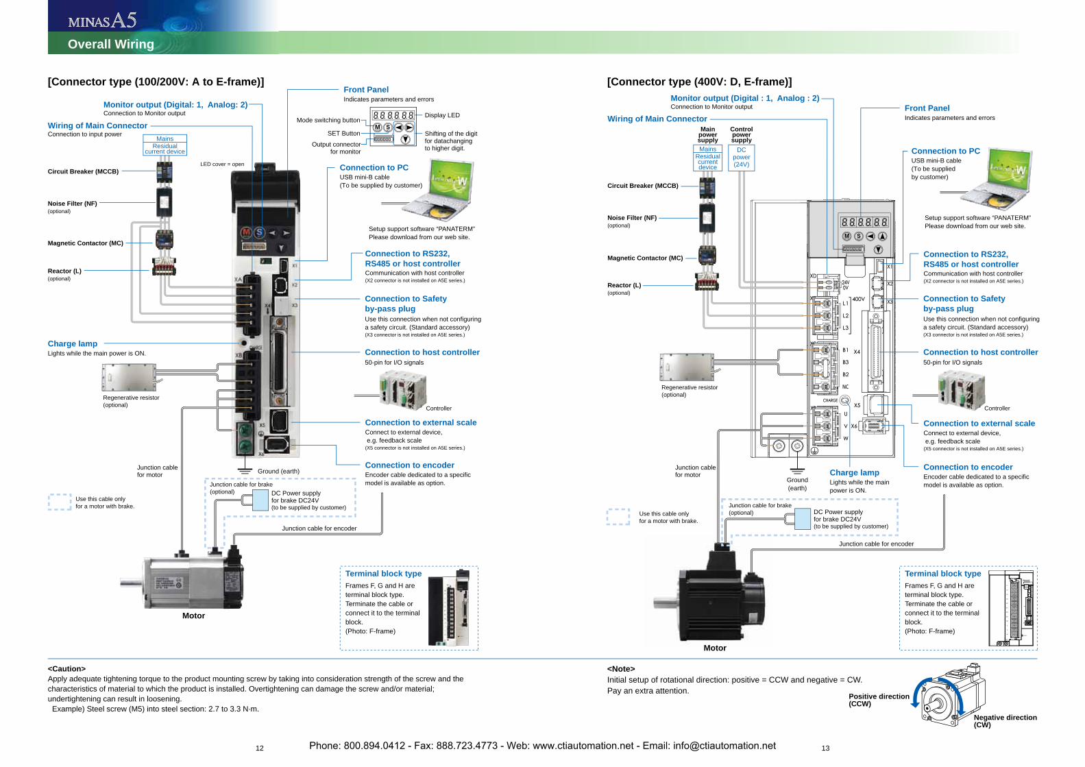
Overall Wiring
Setup support software “PANATERM”Please download from our web site.
Regenerative resistor (optional)
Encoder cable dedicated to a specific model is available as option.
DC Power supply for brake DC24V(to be supplied by customer)
Connect to external device, e.g. feedback scale(X5 connector is not installed on A5E series.)
Communication with host controller(X2 connector is not installed on A5E series.)
Connection to PCUSB mini-B cable(To be supplied by customer)
Connection to PCUSB mini-B cable(To be supplied by customer)
Lights while the main power is ON.
Controller
Junction cablefor motor
Junction cablefor motor
Junction cable for encoder
Connection to RS232, RS485 or host controller
Communication with host controller(X2 connector is not installed on A5E series.)
Connection to RS232, RS485 or host controller
Connection to external scaleConnect to external device, e.g. feedback scale(X5 connector is not installed on A5E series.)
Connection to external scale
Connection to encoderEncoder cable dedicated to a specific model is available as option.
Connection to encoder
Connection to Monitor outputMonitor output (Digital: 1, Analog: 2) Connection to Monitor output
Monitor output (Digital : 1, Analog : 2)
Connection to input powerWiring of Main Connector
Wiring of Main Connector
Use this connection when not configuring a safety circuit. (Standard accessory)(X3 connector is not installed on A5E series.)
Connection to Safety by-pass plug
Use this connection when not configuring a safety circuit. (Standard accessory)(X3 connector is not installed on A5E series.)
Connection to Safety by-pass plug
50-pin for I/O signalsConnection to host controller
50-pin for I/O signalsConnection to host controller
Indicates parameters and errorsFront Panel
Indicates parameters and errorsFront Panel
Charge lamp
Motor
Regenerative resistor (optional)
Junction cable for brake(optional)
Junction cable for brake(optional)
Use this cable only for a motor with brake.
[Connector type (100/200V: A to E-frame)] [Connector type (400V: D, E-frame)]
Reactor (L)
Magnetic Contactor (MC)
Noise Filter (NF)
Circuit Breaker (MCCB)
(optional)
LED cover = open
(optional)
Ground (earth)
<Caution>Apply adequate tightening torque to the product mounting screw by taking into consideration strength of the screw and the characteristics of material to which the product is installed. Overtightening can damage the screw and/or material; undertightening can result in loosening. Example) Steel screw (M5) into steel section: 2.7 to 3.3 N·m.
MainsResidual
current device
Setup support software “PANATERM”Please download from our web site.
DC Power supply for brake DC24V(to be supplied by customer)
Lights while the main power is ON.
Controller
Junction cable for encoder
Charge lamp
Motor
Use this cable only for a motor with brake.
Reactor (L)
Magnetic Contactor (MC)
Noise Filter (NF)
Circuit Breaker (MCCB)
Mainpowersupply
Controlpowersupply
(optional)
(optional)
Ground(earth)
DCpower(24V)
MainsResidualcurrentdevice
Positive direction (CCW)
Negative direction (CW)
Shifting of the digit for datachanging to higher digit.
Display LEDMode switching button
SET ButtonOutput connector
for monitor
6 1
Terminal block type Frames F, G and H are terminal block type. Terminate the cable or connect it to the terminal block.(Photo: F-frame)
Terminal block type Frames F, G and H are terminal block type. Terminate the cable or connect it to the terminal block.(Photo: F-frame)
Phone: 800.894.0412 - Fax: 888.723.4773 - Web: www.ctiautomation.net - Email: [email protected]
14 15
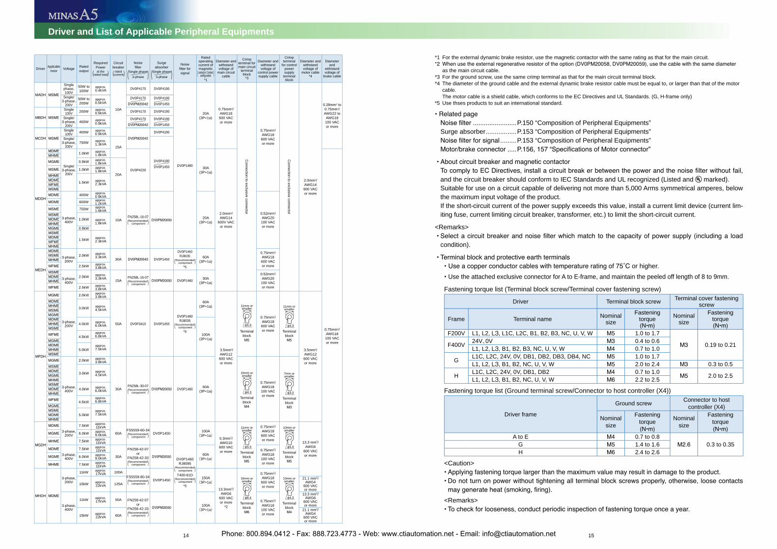
Driver and List of Applicable Peripheral Equipments
*1 For the external dynamic brake resistor, use the magnetic contactor with the same rating as that for the main circuit.
as the main circuit cable.*3 For the ground screw, use the same crimp terminal as that for the main circuit terminal block.*4 The diameter of the ground cable and the external dynamic brake resistor cable must be equal to, or larger than that of the motor
cable.The motor cable is a shield cable, which conforms to the EC Directives and UL Standards. (G, H-frame only)
*5 Use thses products to suit an international standard.
........................P.150 “Composition of Peripheral Equipments”Surge absorber.................P.153 “Composition of Peripheral Equipments”
.........P.153 “Composition of Peripheral Equipments”.....
and the circuit breaker should conform to IEC Standards and UL recognized (Listed and marked).Suitable for use on a circuit capable of delivering not more than 5,000 Arms symmetrical amperes, below the maximum input voltage of the product.If the short-circuit current of the power supply exceeds this value, install a current limit device (current lim-iting fuse, current limiting circuit breaker, transformer, etc.) to limit the short-circuit current.
<Remarks>
condition).
or higher.Use the attached exclusive connector for A to E-frame, and maintain the peeled off length of 8 to 9mm.
Fastening torque list (Terminal block screw/Terminal cover fastening screw)
Driver Terminal block screw Terminal cover fastening screw
Frame Terminal name Nominalsize
Fasteningtorque Nominal
sizeFastening
torque
F200V L1, L2, L3, L1C, L2C, B1, B2, B3, NC, U, V, W 1.0 to 1.7
0.19 to 0.21F400V 24V、0V 0.4 to 0.6L1, L2, L3, B1, B2, B3, NC, U, V, W 0.7 to 1.0
G L1C, L2C, 24V, 0V, DB1, DB2, DB3, DB4, NC 1.0 to 1.7L1, L2, L3, B1, B2, NC, U, V, W 2.0 to 2.4 0.3 to 0.5
H L1C, L2C, 24V, 0V, DB1, DB2 0.7 to 1.0 2.0 to 2.5L1, L2, L3, B1, B2, NC, U, V, W 2.2 to 2.5
Fastening torque list (Ground terminal screw/Connector to host controller (X4))
Driver frame
Ground screw Connector to host controller (X4)
Nominalsize
Fasteningtorque Nominal
size
Fasteningtorque
A to E 0.7 to 0.80.3 to 0.35G 1.4 to 1.6
H 2.4 to 2.6
<Caution>
<Remarks>
Driver Applicablemotor Voltage Rated
output
RequiredPowerat the(rated load)
Circuitbreaker
rated (current)
Noise
(Single phase3-phase )
Surgeabsorber
(Single phase3-phase )
Noise
signal
Ratedoperatingcurrent of magneticcontactor Contact( )
*1
Diameter and withstandvoltage of
main circuit cable
Crimpterminal for main circuit
terminalblock
*3
Diameter and withstandvoltage of
control power supply cable
Crimpterminal
for control powersupply
terminalblock
Diameter and withstandvoltage of
motor cable*4
Diameterand
withstandvoltage of
brake cable
Singlephase,100V
50W to 100W
approx.0.4kVA
10A
DV0P4170 DV0P4190
DV0P1460
20A(3P+1a)
0.75mm2/AWG18600 VACor more
Connection to exclusive connector
0.75mm2/AWG18600 VACor more
Connection to exclusive connector
2.0mm2/AWG14600 VACor more
0.28mm2 to 0.75mm2/AWG22 to
AWG18100 VACor more
Single/3-phase,
200V50W to 200W
approx.0.5kVA
DV0P4170 DV0P4190DV0P1450
Single100V 200W approx.
0.5kVA DV0P4170 DV0P4190
Single/3-phase,
200V400W approx.
0.9kVADV0P4170 DV0P4190
DV0P1450Single100V 400W approx.
0.9kVA DV0P4190
Single/3-phase,
200V750W approx.
1.3kVA15A
DV0P4190DV0P1450Single/
3-phase,200V
1.0kW approx.1.8kVA
DV0P4220 30A(3P+1a)
2.0mm2/AWG14
600V VACor more
0.75mm2/AWG18100 VACor more
0.9kW approx.1.8kVA
20A1.0kW approx.
1.8kVA
1.5kW approx.2.3kVA
3-phase,400V
400W approx.0.9kVA
10AFN258L-16-07Recommended( component )
20A(3P+1a)
0.52mm2/AWG20100 VACor more
600W approx.1.2kVA
750W approx.1.6kVA
1.0kW approx.1.8kVA
0.9kW
1.5kW approx.2.3kVA
3-phase,200V
2.0kW approx.3.3kVA 30A DV0P1450
DV0P1460RJ8035
Recommended( component )*5
60A(3P+1a)
0.75mm2/AWG18600 VACor more2.5kW approx.
3.8kVA
3-phase,400V
2.0kW approx.3.3kVA 15A
FN258L-16-07Recommended( component ) DV0P1460 30A
(3P+1a)
0.52mm2/AWG20100 VACor more2.5kW approx.
3.8kVA
3-phase,200V
2.0kW approx.3.8kVA
50A DV0P3410 DV0P1450
DV0P1460RJ8035
Recommended( component )*5
60A(3P+1a)
3.5mm2/AWG12600 VACor more
11mm orsmaller
Terminalblock
0.75mm2/AWG18600 VACor more
11mm orsmaller
Terminalblock
3.5mm2/AWG12600 VACor more
3.0kW approx.4.5kVA
4.0kW approx.6.0kVA
100A(3P+1a)4.5kW
approx.6.8kVA
approx.7.5kVA5.0kW
3-phase,400V
2.0kW approx.3.8kVA
30AFN258L-30-07Recommended( component ) DV0P1460 60A
(3P+1a)
10mm orsmaller
Terminalblock
0.75mm2/AWG18100 VACor more
7mm orsmaller
Terminalblock
3.0kW approx.4.5kVA
4.0kW approx.6.0kVA
4.5kWapprox.6.8kVA
approx.7.5kVA5.0kW
3-phase,200V
7.5kW approx.11kVA
60AFS5559-60-34
Recommended( component ) DV0P1450
DV0P1460RJ8095
Recommended( component )T400-61D
Recommended( component )*5
100A(3P+1a)
5.3mm2/AWG10600 VACor more
11mm orsmaller
Terminalblock
0.75mm2/AWG18600 VACor more
10mm orsmaller
Terminalblock
13.3 mm2/AWG6
600 VACor more
6.0kW approx.9.0kVA
7.5kW approx.11kVA
3-phase,400V
7.5kW approx.11kVA
30A
FN258-42-07or
FN258-42-33Recommended( component )
60A(3P+1a)
0.75mm2/AWG18100 VACor more
6.0kW approx.9.0kVA
7.5kW approx.11kVA
3-phase,200V
11kW approx.17kVA 100A
FS5559-80-34Recommended( component ) DV0P1450 150A
(3P+1a)
13.3mm2/AWG6
600 VACor more
*2
16mm orsmaller
Terminalblock
0.75mm2/AWG18600 VACor more
10mm orsmaller
Terminalblock
15kW approx.22kVA 125A
21.1 mm2/AWG4
600 VACor more
3-phase,400V
11kW approx.17kVA 50A FN258-42-07
orFN258-42-33Recommended( component )
100A(3P+1a)
0.75mm2/AWG18100 VACor more
13.3 mm2/AWG6
600 VACor more
15kW approx.22kVA 60A
21.1 mm2/AWG4
600 VACor more
Phone: 800.894.0412 - Fax: 888.723.4773 - Web: www.ctiautomation.net - Email: [email protected]
16 17
Driver
Mo
tor
Op
tion
sIn
form
ation
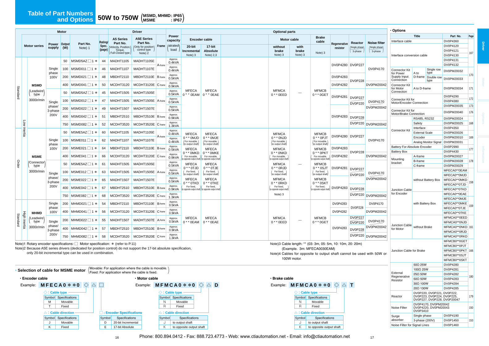
Table of Part Numbersand Options 50W to 750W (MSMD, MHMD: IP65
MSME : IP67)D
river
Title Part No. Page
Interface cable DV0P4360
167Interface conversion cable
DV0P4120DV0P4121DV0P4130DV0P4131DV0P4132
Connector Kit for Power Supply Input Connection
A to D-frame
Single row type DV0PM20032
170Double row type DV0PM20033
Connector Kit for Motor Connection
A to D-frame DV0PM20034 171
Connector Kit for Motor/Encoder Connection
DV0P4290172
DV0P4380DV0PM20035 173
Connector Kit for Motor/Brake Connection DV0PM20040 176
Connector Kit
RS485, RS232 DV0PM20024168Safety DV0PM20025
Interface DV0P4350External Scale DV0PM20026
169Encoder DV0PM20010Analog Monitor Signal DV0PM20031
Battery For Absolute Encoder DV0P2990177
Battery Box DV0P4430
Mountingbracket
A-frame DV0PM20027178B-frame DV0PM20028
C-frame DV0PM20029
Junction Cable for Encoder
without Battery Box
MFECA0**0EAM
158
MFECA0**0MJDMFECA0**0MKDMFECA0**0TJDMFECA0**0TKD
with Battery Box
MFECA0**0EAEMFECA0**0MJE
159MFECA0**0MKEMFECA0**0TJEMFECA0**0TKE
Junction Cable for Motor without Brake
MFMCA0**0EED
161MFMCA0**0NJDMFMCA0**0NKDMFMCA0**0RJDMFMCA0**0RKD
Junction Cable for Brake
MFMCB0**0GET
166MFMCB0**0PJTMFMCB0**0PKTMFMCB0**0SJTMFMCB0**0SKT
ExternalRegenerativeResistor
DV0P4280
180
DV0P4281DV0P4282DV0P4283DV0P4284DV0P4285
ReactorDV0P220, DV0P221, DV0P222, DV0P223, DV0P224, DV0P225, DV0P227, DV0P228, DV0P20047
179
Noise FilterDV0P4170, DV0PM20042DV0P4220, DV0PM20043DV0P3410
150
Surgeabsorber
Single phase DV0P41901533-phase (200V) DV0P1450
Noise Filter for Signal Lines DV0P1460
Motor DriverPower
capacity
atrated( load )
Optional parts
Motor series Powersupply
Output(W)
Part No.Note) 1
Rating/Spec.(page)
A5 Series Part No.
Velocity, Position,Torque,( Full-Closed type )
A5E Series Part No.
Only for position( control type )Note) 2
Frame
Encoder cable Motor cableBrakecable
Regenerativeresistor
Reactor
(Single phase3-phase ) (Single phase
3-phase )20-bitIncremental
Note) 3
17-bitAbsoluteNote) 2,3
withoutbrakeNote) 3
withbrakeNote) 3
Note) 3
Standard
Low inertia
MSMD
Leadwire( type )3000r/min
Singlephase100V
50 MSMD5AZ□ 1* 44 MADHT1105 MADHT1105EA-frame
Approx.0.4kVA
MFECA0 * * 0EAM
MFECA0 * * 0EAE
MFMCA0 * * 0EED — MFMCB
0 * * 0GET
DV0P4280 DV0P227DV0P4170100 MSMD011□ 1* 46 MADHT1107 MADHT1107E Approx.
0.4kVA
200 MSMD021□ 1* 48 MBDHT2110 MBDHT2110E B-frameApprox.0.5kVA DV0P4283
DV0P228400 MSMD041□ 1* 50 MCDHT3120 MCDHT3120E C-frame
Approx.0.9kVA DV0P4282 DV0PM20042
Singlephase/
3-phase200V
50 MSMD5AZ□ 1* 45 MADHT1505 MADHT1505E
A-frame
Approx.0.5kVA
DV0P4281 DV0P227DV0P220 DV0P4170
DV0PM20042
100 MSMD012□ 1* 47 MADHT1505 MADHT1505E Approx.0.5kVA
200 MSMD022□ 1* 49 MADHT1507 MADHT1507E Approx.0.5kVA
DV0P4283400 MSMD042□ 1* 51 MBDHT2510 MBDHT2510E B-frameApprox.0.9kVA DV0P228
DV0P220750 MSMD082□ 1* 52 MCDHT3520 MCDHT3520E C-frameApprox.1.3kVA DV0PM20042
Order
MSME
Connector( type )3000r/min
Singlephase100V
50 MSME5AZ□ 1* 60 MADHT1105 MADHT1105EA-frame
Approx.0.4kVA MFECA
0 * * 0MJDFor movable,(to output shaft)MFECA
0 * * 0MKDFor movable,(to opposite output shaft)MFECA
0 * * 0TJDFor fixed,(to output shaft)
MFECA0 * * 0TKD
For fixed,(to opposite output shaft)
MFECA0 * * 0MJE
For movable,(to output shaft)MFECA
0 * * 0MKEFor movable,(to opposite output shaft)MFECA
0 * * 0TJEFor fixed,(to output shaft)
MFECA0 * * 0TKE
For fixed,(to opposite output shaft)
MFMCA0 * * 0NJDFor movable,(to output shaft)MFMCA
0 * * 0NKDFor movable,(to opposite output shaft)MFMCA
0 * * 0RJDFor fixed,(to output shaft)
MFMCA0 * * 0RKD
For fixed,(to opposite output shaft)Note) 3
—
MFMCB0 * * 0PJTFor movable,(to output shaft)MFMCB
0 * * 0PKTFor movable,(to opposite output shaft)MFMCB
0 * * 0SJTFor fixed,(to output shaft)
MFMCB0 * * 0SKT
For fixed,(to opposite output shaft)
DV0P4280 DV0P227DV0P4170100 MSME011□ 1* 62 MADHT1107 MADHT1107E Approx.
0.4kVA
200 MSME021□ 1* 64 MBDHT2110 MBDHT2110E B-frameApprox.0.5kVA DV0P4283
DV0P228400 MSME041□ 1* 66 MCDHT3120 MCDHT3120E C-frame
Approx.0.9kVA DV0P4282 DV0PM20042
Singlephase/
3-phase200V
50 MSME5AZ□ 1* 61 MADHT1505 MADHT1505E
A-frame
Approx.0.5kVA
DV0P4281 DV0P227DV0P220 DV0P4170
DV0PM20042
100 MSME012□ 1* 63 MADHT1505 MADHT1505E Approx.0.5kVA
200 MSME022□ 1* 65 MADHT1507 MADHT1507E Approx.0.5kVA
DV0P4283400 MSME042□ 1* 67 MBDHT2510 MBDHT2510E B-frameApprox.0.9kVA DV0P228
DV0P220750 MSME082□ 1* 68 MCDHT3520 MCDHT3520E C-frameApprox.1.3kVA DV0PM20042
Standard
High inertia
MHMD
Leadwire( type )3000r/min
Singlephase100V
200 MHMD021□ 1* 54 MBDHT2110 MBDHT2110E B-frameApprox.0.5kVA
MFECA0 * * 0EAM
MFECA0 * * 0EAE
MFMCA0 * * 0EED — MFMCB
0 * * 0GET
DV0P4283DV0P228
DV0P4170
400 MHMD041□ 1* 56 MCDHT3120 MCDHT3120E C-frameApprox.0.9kVA DV0P4282 DV0PM20042
Singlephase/
3-phase200V
200 MHMD022□ 1* 55 MADHT1507 MADHT1507E A-frameApprox.0.5kVA
DV0P4283
DV0P227DV0P220 DV0P4170
DV0PM20042400 MHMD042□ 1* 57 MBDHT2510 MBDHT2510E B-frameApprox.0.9kVA DV0P228
DV0P220750 MHMD082□ 1* 58 MCDHT3520 MCDHT3520E C-frameApprox.1.3kVA DV0PM20042
□ * (refer to P.11) Note)2 Because A5E series drivers (dedicated for position control) do not support the 17-bit absolute specification,
only 20-bit incremental type can be used in combination.
Note)3
Note)4
◇:Cable type
SymbolM MovableT Fixed
△:Cable direction
SymbolJ MovableK Fixed
Selection of cable for MSME motor( )
M F E C A 0**0 ◇ △ □◇:Cable type
SymbolN MovableR Fixed
△:Cable direction
SymbolJ to output shaftK to opposite output shaft
M F M C A 0**0 ◇ △ D◇:Cable type
SymbolN MovableR Fixed
△:Cable direction
SymbolJ to output shaftK to opposite output shaft
M F M C A 0**0 ◇ △ T
□Symbol
D 20-bit IncrementalE 17-bit Absolute
Phone: 800.894.0412 - Fax: 888.723.4773 - Web: www.ctiautomation.net - Email: [email protected]
18 19
Driver
Mo
tor
Op
tion
sIn
form
ation
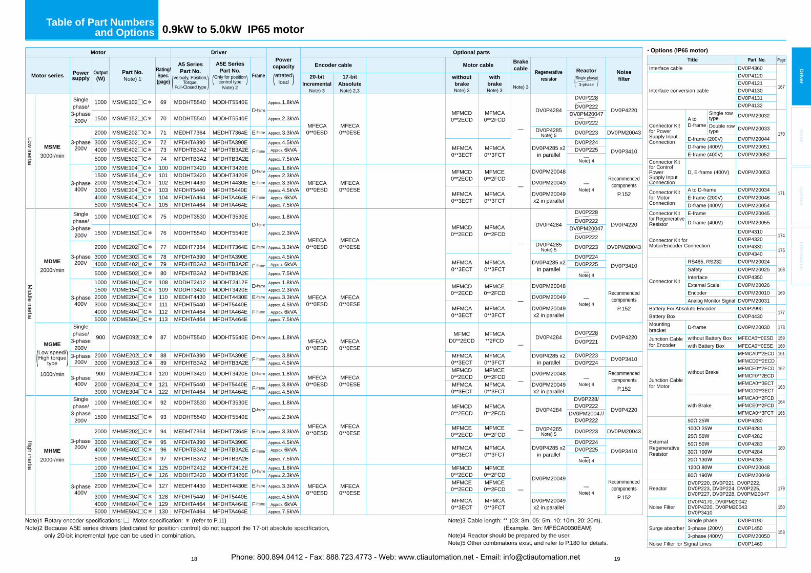
Table of Part Numbersand Options 0.9kW to 5.0kW IP65 motor
□ * (refer to P.11) Note)2 Because A5E series drivers (dedicated for position control) do not support the 17-bit absolute specification, only 20-bit incremental type can be used in combination.
Motor DriverPower
capacity
atrated( load )
Optional parts
Motor series Powersupply
Output(W)
Part No.Note) 1
Rating/Spec.(page)
A5 Series Part No.
Velocity, Position,Torque,( Full-Closed type )
A5E Series Part No.
Only for position( control type )Note) 2
Frame
Encoder cable Motor cableBrakecable
Regenerativeresistor
Reactor
(Single phase3-phase )
Noise20-bit
IncrementalNote) 3
17-bitAbsoluteNote) 2,3
withoutbrakeNote) 3
withbrakeNote) 3
Note) 3
Low inertia
MSME
3000r/min
Singlephase/
3-phase200V
1000 MSME102□C* 69 MDDHT5540 MDDHT5540ED-frame
Approx. 1.8kVA
MFECA0**0ESD
MFECA0**0ESE
MFMCD0**2ECD
MFMCA0**2FCD
—
DV0P4284
DV0P228DV0P222 DV0P4220
1500 MSME152□C* 70 MDDHT5540 MDDHT5540E Approx. 2.3kVADV0PM20047
DV0P222
3-phase200V
2000 MSME202□C* 71 MEDHT7364 MEDHT7364E E-frame Approx. 3.3kVA DV0P4285Note) 5 DV0P223 DV0PM20043
3000 MSME302□C* 72 MFDHTA390 MFDHTA390EF-frame
Approx. 4.5kVAMFMCA0**3ECT
MFMCA0**3FCT
DV0P4285 x2 in parallel
DV0P224DV0P34104000 MSME402□C* 73 MFDHTB3A2 MFDHTB3A2E Approx. 6kVA DV0P225
5000 MSME502□C* 74 MFDHTB3A2 MFDHTB3A2E Approx. 7.5kVA —Note) 4
3-phase400V
1000 MSME104□C* 100 MDDHT3420 MDDHT3420E D-frameApprox. 1.8kVA
MFECA0**0ESD
MFECA0**0ESE
MFMCD0**2ECD
MFMCE0**2FCD
—
DV0PM20048
—Note) 4
Recommendedcomponents
P.152
1500 MSME154□C* 101 MDDHT3420 MDDHT3420E Approx. 2.3kVA2000 MSME204□C* 102 MEDHT4430 MEDHT4430E E-frame Approx. 3.3kVA DV0PM200493000 MSME304□C* 103 MFDHT5440 MFDHT5440E
F-frameApprox. 4.5kVA
MFMCA0**3ECT
MFMCA0**3FCT
DV0PM20049x2 in parallel4000 MSME404□C* 104 MFDHTA464 MFDHTA464E Approx. 6kVA
5000 MSME504□C* 105 MFDHTA464 MFDHTA464E Approx. 7.5kVA
Middle inertia
MDME
2000r/min
Singlephase/
3-phase200V
1000 MDME102□C* 75 MDDHT3530 MDDHT3530ED-frame
Approx. 1.8kVA
MFECA0**0ESD
MFECA0**0ESE
MFMCD0**2ECD
MFMCA0**2FCD
—
DV0P4284
DV0P228DV0P222 DV0P4220
1500 MDME152□C* 76 MDDHT5540 MDDHT5540E Approx. 2.3kVADV0PM20047
DV0P222
3-phase200V
2000 MDME202□C* 77 MEDHT7364 MEDHT7364E E-frame Approx. 3.3kVA DV0P4285Note) 5 DV0P223 DV0PM20043
3000 MDME302□C* 78 MFDHTA390 MFDHTA390EF-frame
Approx. 4.5kVAMFMCA0**3ECT
MFMCA0**3FCT
DV0P4285 x2 in parallel
DV0P224DV0P34104000 MDME402□C* 79 MFDHTB3A2 MFDHTB3A2E Approx. 6kVA DV0P225
5000 MDME502□C* 80 MFDHTB3A2 MFDHTB3A2E Approx. 7.5kVA —Note) 4
3-phase400V
1000 MDME104□C* 108 MDDHT2412 MDDHT2412E D-frameApprox. 1.8kVA
MFECA0**0ESD
MFECA0**0ESE
MFMCD0**2ECD
MFMCE0**2FCD
—
DV0PM20048
—Note) 4
Recommendedcomponents
P.152
1500 MDME154□C* 109 MDDHT3420 MDDHT3420E Approx. 2.3kVA2000 MDME204□C* 110 MEDHT4430 MEDHT4430E E-frame Approx. 3.3kVA DV0PM200493000 MDME304□C* 111 MFDHT5440 MFDHT5440E
F-frameApprox. 4.5kVA
MFMCA0**3ECT
MFMCA0**3FCT
DV0PM20049x2 in parallel4000 MDME404□C* 112 MFDHTA464 MFDHTA464E Approx. 6kVA
5000 MDME504□C* 113 MFDHTA464 MFDHTA464E Approx. 7.5kVA
MGME
Low speed/High torque( type )1000r/min
Singlephase/
3-phase200V
900 MGME092□C* 87 MDDHT5540 MDDHT5540E D-frame Approx. 1.8kVAMFECA0**0ESD
MFECA0**0ESE
MFMCD0**2ECD
MFMCA**2FCD
—DV0P4284
DV0P228DV0P221
DV0P4220
3-phase200V
2000 MGME202□C* 88 MFDHTA390 MFDHTA390E F-frameApprox. 3.8kVA MFMCA
0**3ECTMFMCA0**3FCT
DV0P4285 x2 in parallel
DV0P223 DV0P34103000 MGME302□C* 89 MFDHTB3A2 MFDHTB3A2E Approx. 4.5kVA DV0P224
3-phase400V
900 MGME094□C* 120 MDDHT3420 MDDHT3420E D-frame Approx. 1.8kVAMFECA0**0ESD
MFECA0**0ESE
MFMCD0**2ECD
MFMCE0**2FCD
—DV0PM20048
—Note) 4
Recommendedcomponents
P.1522000 MGME204□C* 121 MFDHT5440 MFDHT5440E F-frame
Approx. 3.8kVA MFMCA0**3ECT
MFMCA0**3FCT
DV0PM20049x2 in parallel3000 MGME304□C* 122 MFDHTA464 MFDHTA464E Approx. 4.5kVA
High inertia
MHME
2000r/min
Singlephase/
3-phase200V
1000 MHME102□C* 92 MDDHT3530 MDDHT3530ED-frame
Approx. 1.8kVA
MFECA0**0ESD
MFECA0**0ESE
MFMCD0**2ECD
MFMCA0**2FCD
—
DV0P4284
DV0P228/DV0P222
DV0P42201500 MHME152□C* 93 MDDHT5540 MDDHT5540E Approx. 2.3kVA DV0PM20047/
DV0P222
3-phase200V
2000 MHME202□C* 94 MEDHT7364 MEDHT7364E E-frame Approx. 3.3kVA MFMCE0**2ECD
MFMCE0**2FCD
DV0P4285Note) 5 DV0P223 DV0PM20043
3000 MHME302□C* 95 MFDHTA390 MFDHTA390EF-frame
Approx. 4.5kVAMFMCA0**3ECT
MFMCA0**3FCT
DV0P4285 x2 in parallel
DV0P224DV0P34104000 MHME402□C* 96 MFDHTB3A2 MFDHTB3A2E Approx. 6kVA DV0P225
5000 MHME502□C* 97 MFDHTB3A2 MFDHTB3A2E Approx. 7.5kVA —Note) 4
3-phase400V
1000 MHME104□C* 125 MDDHT2412 MDDHT2412E D-frameApprox. 1.8kVA
MFECA0**0ESD
MFECA0**0ESE
MFMCD0**2ECD
MFMCE0**2FCD
—
DV0PM20049—
Note) 4
Recommendedcomponents
P.152
1500 MHME154□C* 126 MDDHT3420 MDDHT3420E Approx. 2.3kVA
2000 MHME204□C* 127 MEDHT4430 MEDHT4430E E-frame Approx. 3.3kVA MFMCE0**2ECD
MFMCE0**2FCD
3000 MHME304□C* 128 MFDHT5440 MFDHT5440EF-frame
Approx. 4.5kVAMFMCA0**3ECT
MFMCA0**3FCT
DV0PM20049x2 in parallel4000 MHME404□C* 129 MFDHTA464 MFDHTA464E Approx. 6kVA
5000 MHME504□C* 130 MFDHTA464 MFDHTA464E Approx. 7.5kVA
Title Part No. Page
Interface cable DV0P4360
167Interface conversion cable
DV0P4120DV0P4121DV0P4130DV0P4131DV0P4132
Connector Kitfor Power Supply Input Connection
A to D-frame
Single row type DV0PM20032
170Double row type DV0PM20033
E-frame (200V) DV0PM20044D-frame (400V) DV0PM20051E-frame (400V) DV0PM20052
Connector Kitfor Control PowerSupply Input Connection
D, E-frame (400V) DV0PM20053
171Connector Kitfor Motor Connection
A to D-frame DV0PM20034E-frame (200V) DV0PM20046D-frame (400V) DV0PM20054
Connector Kitfor Regenerative Resistor
E-frame DV0PM20045
D-frame (400V) DV0PM20055
Connector Kit for Motor/Encoder Connection
DV0P4310174
DV0P4320DV0P4330
175DV0P4340
Connector Kit
RS485, RS232 DV0PM20024168Safety DV0PM20025
Interface DV0P4350External Scale DV0PM20026
169Encoder DV0PM20010Analog Monitor Signal DV0PM20031
Battery For Absolute Encoder DV0P2990177
Battery Box DV0P4430Mountingbracket D-frame DV0PM20030 178
Junction Cable for Encoder
without Battery Box MFECA0**0ESD 159with Battery Box MFECA0**0ESE 160
Junction Cable for Motor
without Brake
MFMCA0**2ECD 161MFMCD0**2ECD
162MFMCE0**2ECDMFMCF0**2ECDMFMCA0**3ECT
163MFMCD0**3ECT
with BrakeMFMCA0**2FCD
164MFMCE0**2FCDMFMCA0**3FCT 165
ExternalRegenerativeResistor
DV0P4280
180
DV0P4281DV0P4282DV0P4283DV0P4284DV0P4285DV0PM20048DV0PM20049
ReactorDV0P220, DV0P221, DV0P222, DV0P223, DV0P224, DV0P225, DV0P227, DV0P228, DV0PM20047
179
Noise FilterDV0P4170, DV0PM20042DV0P4220, DV0PM20043DV0P3410
150
Surge absorberSingle phase DV0P4190
1533-phase (200V) DV0P14503-phase (400V) DV0PM20050
Noise Filter for Signal Lines DV0P1460
Note)3 Note)4 Reactor should be prepared by the user.Note)5 Other combinations exist, and refer to P.180 for details.
Phone: 800.894.0412 - Fax: 888.723.4773 - Web: www.ctiautomation.net - Email: [email protected]
20
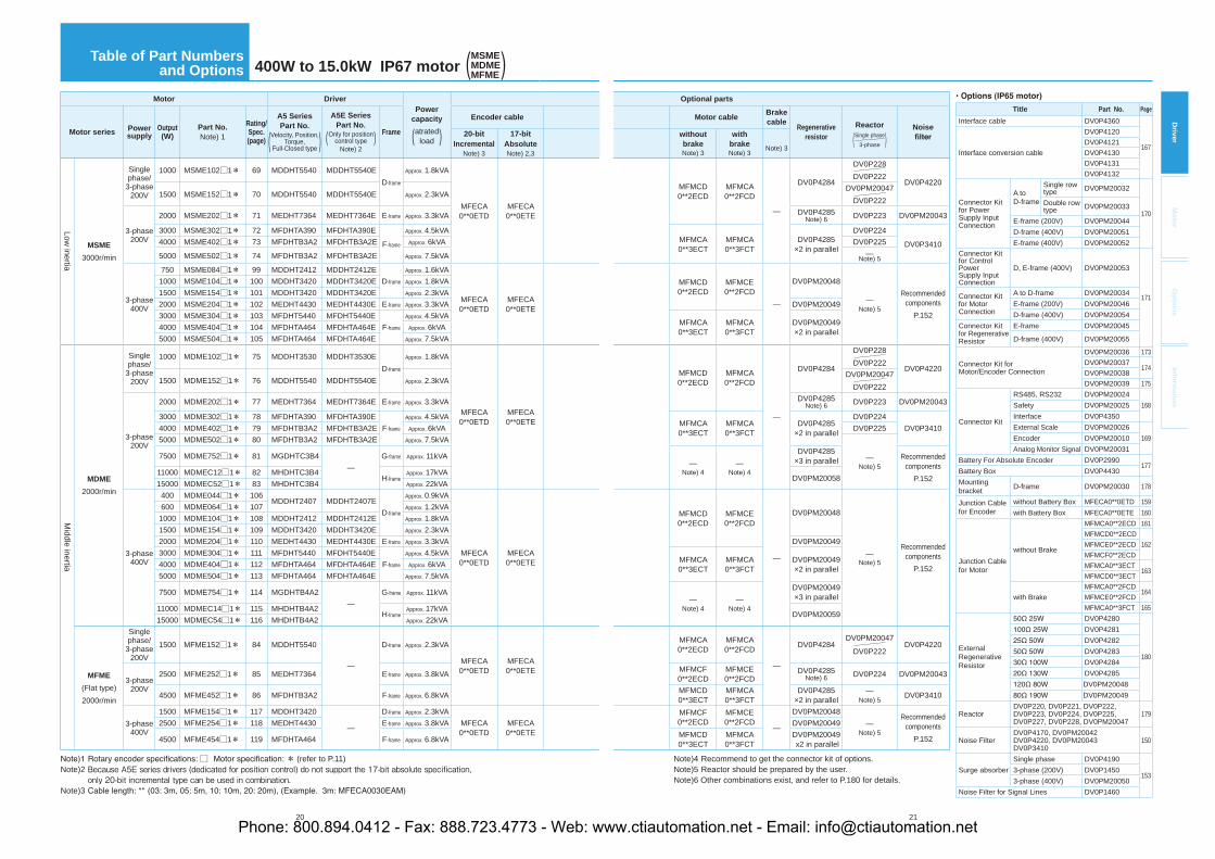
Table of Part Numbersand Options 400W to 15.0kW IP67 motor (MSME
MDMEMFME)
Motor DriverPower
capacity
atrated( load )Motor series Powersupply
Output(W)
Part No.Note) 1
Rating/Spec.(page)
A5 Series Part No.
Velocity, Position,Torque,( Full-Closed type )
A5E Series Part No.
Only for position( control type )Note) 2
Frame
Encoder cable
20-bitIncremental
Note) 3
17-bitAbsolute Note) 2,3
Low inertia
MSME
3000r/min
Single phase/
3-phase 200V
1000 MSME102□1* 69 MDDHT5540 MDDHT5540ED-frame
Approx. 1.8kVA
MFECA0**0ETD
MFECA0**0ETE
1500 MSME152□1* 70 MDDHT5540 MDDHT5540E Approx. 2.3kVA
3-phase 200V
2000 MSME202□1* 71 MEDHT7364 MEDHT7364E E-frame Approx. 3.3kVA
3000 MSME302□1* 72 MFDHTA390 MFDHTA390E
F-frame
Approx. 4.5kVA4000 MSME402□1* 73 MFDHTB3A2 MFDHTB3A2E Approx. 6kVA
5000 MSME502□1* 74 MFDHTB3A2 MFDHTB3A2E Approx. 7.5kVA
3-phase 400V
750 MSME084□1* 99 MDDHT2412 MDDHT2412ED-frame
Approx. 1.6kVA
MFECA0**0ETD
MFECA0**0ETE
1000 MSME104□1* 100 MDDHT3420 MDDHT3420E Approx. 1.8kVA1500 MSME154□1* 101 MDDHT3420 MDDHT3420E Approx. 2.3kVA2000 MSME204□1* 102 MEDHT4430 MEDHT4430E E-frame Approx. 3.3kVA3000 MSME304□1* 103 MFDHT5440 MFDHT5440E
F-frame
Approx. 4.5kVA4000 MSME404□1* 104 MFDHTA464 MFDHTA464E Approx. 6kVA5000 MSME504□1* 105 MFDHTA464 MFDHTA464E Approx. 7.5kVA
Middle inertia
MDME
2000r/min
Single phase/
3-phase 200V
1000 MDME102□1* 75 MDDHT3530 MDDHT3530ED-frame
Approx. 1.8kVA
MFECA0**0ETD
MFECA0**0ETE
1500 MDME152□1* 76 MDDHT5540 MDDHT5540E Approx. 2.3kVA
3-phase 200V
2000 MDME202□1* 77 MEDHT7364 MEDHT7364E E-frame Approx. 3.3kVA
3000 MDME302□1* 78 MFDHTA390 MFDHTA390EF-frame
Approx. 4.5kVA4000 MDME402□1* 79 MFDHTB3A2 MFDHTB3A2E Approx. 6kVA5000 MDME502□1* 80 MFDHTB3A2 MFDHTB3A2E Approx. 7.5kVA
7500 MDME752□1* 81 MGDHTC3B4—
G-frame Approx. 11kVA
11000 MDMEC12□1* 82 MHDHTC3B4H-frame
Approx. 17kVA15000 MDMEC52□1* 83 MHDHTC3B4 Approx. 22kVA
3-phase 400V
400 MDME044□1* 106MDDHT2407 MDDHT2407E
D-frame
Approx. 0.9kVA
MFECA0**0ETD
MFECA0**0ETE
600 MDME064□1* 107 Approx. 1.2kVA1000 MDME104□1* 108 MDDHT2412 MDDHT2412E Approx. 1.8kVA1500 MDME154□1* 109 MDDHT3420 MDDHT3420E Approx. 2.3kVA2000 MDME204□1* 110 MEDHT4430 MEDHT4430E E-frame Approx. 3.3kVA3000 MDME304□1* 111 MFDHT5440 MFDHT5440E
F-frame
Approx. 4.5kVA4000 MDME404□1* 112 MFDHTA464 MFDHTA464E Approx. 6kVA5000 MDME504□1* 113 MFDHTA464 MFDHTA464E Approx. 7.5kVA
7500 MDME754□1* 114 MGDHTB4A2—
G-frame Approx. 11kVA
11000 MDMEC14□1* 115 MHDHTB4A2H-frame
Approx. 17kVA15000 MDMEC54□1* 116 MHDHTB4A2 Approx. 22kVA
MFME
(Flat type) 2000r/min
Single phase/
3-phase 200V
1500 MFME152□1* 84 MDDHT5540
—
D-frame Approx. 2.3kVA
MFECA0**0ETD
MFECA0**0ETE
3-phase 200V
2500 MFME252□1* 85 MEDHT7364 E-frame Approx. 3.8kVA
4500 MFME452□1* 86 MFDHTB3A2 F-frame Approx. 6.8kVA
3-phase 400V
1500 MFME154□1* 117 MDDHT3420
—
D-frame Approx. 2.3kVAMFECA0**0ETD
MFECA0**0ETE
2500 MFME254□1* 118 MEDHT4430 E-frame Approx. 3.8kVA
4500 MFME454□1* 119 MFDHTA464 F-frame Approx. 6.8kVA
□ * (refer to P.11) Note)2 Because A5E series drivers (dedicated for position control) do not support the 17-bit absolute specification, only 20-bit incremental type can be used in combination.Note)3
21
Driver
Mo
tor
Op
tion
sIn
form
ation
Optional parts
Motor cableBrake cable
Regenerativeresistor
Reactor
(Single phase3-phase )
Noisewithout brakeNote) 3
with brakeNote) 3
Note) 3
MFMCD0**2ECD
MFMCA0**2FCD
—
DV0P4284
DV0P228DV0P222
DV0P4220DV0PM20047
DV0P222DV0P4285
Note) 6 DV0P223 DV0PM20043
MFMCA0**3ECT
MFMCA0**3FCT
DV0P4285×2 in parallel
DV0P224
DV0P3410DV0P225—
Note) 5
MFMCD0**2ECD
MFMCE0**2FCD
—
DV0PM20048
—Note) 5
Recommended components
P.152DV0PM20049
MFMCA0**3ECT
MFMCA0**3FCT
DV0PM20049 ×2 in parallel
MFMCD0**2ECD
MFMCA0**2FCD
—
DV0P4284
DV0P228DV0P222
DV0P4220DV0PM20047
DV0P222DV0P4285
Note) 6 DV0P223 DV0PM20043
MFMCA0**3ECT
MFMCA0**3FCT
DV0P4285×2 in parallel
DV0P224DV0P3410DV0P225
—Note) 5—
Note) 4—
Note) 4
DV0P4285×3 in parallel Recommended
componentsP.152DV0PM20058
MFMCD0**2ECD
MFMCE0**2FCD
—
DV0PM20048
—Note) 5
Recommended components
P.152
DV0PM20049
MFMCA0**3ECT
MFMCA0**3FCT
DV0PM20049 ×2 in parallel
—Note) 4
—Note) 4
DV0PM20049 ×3 in parallel
DV0PM20059
MFMCA0**2ECD
MFMCA0**2FCD
—
DV0P4284DV0PM20047
DV0P222DV0P4220
MFMCF0**2ECD
MFMCE0**2FCD
DV0P4285Note) 6 DV0P224 DV0PM20043
MFMCD0**3ECT
MFMCA0**3FCT
DV0P4285×2 in parallel
—Note) 5 DV0P3410
MFMCF0**2ECD
MFMCE0**2FCD
—
DV0PM20048—
Note) 5
Recommended components
P.152
DV0PM20049MFMCD0**3ECT
MFMCA0**3FCT
DV0PM20049 x2 in parallel
Title Part No. Page
Interface cable DV0P4360
167Interface conversion cable
DV0P4120DV0P4121DV0P4130DV0P4131DV0P4132
Connector Kitfor Power Supply Input Connection
A to D-frame
Single row type DV0PM20032
170Double row type DV0PM20033
E-frame (200V) DV0PM20044D-frame (400V) DV0PM20051E-frame (400V) DV0PM20052
Connector Kitfor Control Power Supply Input Connection
D, E-frame (400V) DV0PM20053
171Connector Kitfor Motor Connection
A to D-frame DV0PM20034E-frame (200V) DV0PM20046D-frame (400V) DV0PM20054
Connector Kitfor Regenerative Resistor
E-frame DV0PM20045
D-frame (400V) DV0PM20055
Connector Kit for Motor/Encoder Connection
DV0PM20036 173DV0PM20037
174DV0PM20038DV0PM20039 175
Connector Kit
RS485, RS232 DV0PM20024168Safety DV0PM20025
Interface DV0P4350External Scale DV0PM20026
169Encoder DV0PM20010Analog Monitor Signal DV0PM20031
Battery For Absolute Encoder DV0P2990177
Battery Box DV0P4430Mounting bracket D-frame DV0PM20030 178
Junction Cable for Encoder
without Battery Box MFECA0**0ETD 159with Battery Box MFECA0**0ETE 160
Junction Cable for Motor
without Brake
MFMCA0**2ECD 161MFMCD0**2ECD
162MFMCE0**2ECDMFMCF0**2ECDMFMCA0**3ECT
163MFMCD0**3ECT
with BrakeMFMCA0**2FCD
164MFMCE0**2FCDMFMCA0**3FCT 165
External Regenerative Resistor
DV0P4280
180
DV0P4281DV0P4282DV0P4283DV0P4284DV0P4285DV0PM20048DV0PM20049
ReactorDV0P220, DV0P221, DV0P222, DV0P223, DV0P224, DV0P225, DV0P227, DV0P228, DV0PM20047
179
Noise FilterDV0P4170, DV0PM20042DV0P4220, DV0PM20043DV0P3410
150
Surge absorberSingle phase DV0P4190
1533-phase (200V) DV0P14503-phase (400V) DV0PM20050
Noise Filter for Signal Lines DV0P1460
Note)4 Recommend to get the connector kit of options.Note)5 Reactor should be prepared by the user.Note)6 Other combinations exist, and refer to P.180 for details.
Phone: 800.894.0412 - Fax: 888.723.4773 - Web: www.ctiautomation.net - Email: [email protected]
22 23
Driver
Mo
tor
Op
tion
sIn
form
ation
Motor DriverPower
capacity
atrated( load )
Optional parts
Motor series Powersupply
Output(W)
Part No.Note) 1
Rating/Spec.(page)
A5 Series Part No.
Velocity, Position,Torque,( Full-Closed type )
A5E Series Part No.
Only for position( control type )Note) 2
Frame
Encoder cable Motor cableBrakecable
Regenerativeresistor
Reactor
(Single phase3-phase )
Noise20-bit
IncrementalNote) 3
17-bitAbsoluteNote) 2,3
withoutbrakeNote) 3
withbrakeNote) 3
Note) 3
Middle inertia
MGME
Low speed/High torque( type )1000r/min
Singlephase/
3-phase200V
900 MGME092□1* 87 MDDHT5540 MDDHT5540E D-frame Approx. 1.8kVA
MFECA0**0ETD
MFECA0**0ETE
MFMCD0**2ECD
MFMCA0**2FCD
—
DV0P4284DV0P228DV0P221
DV0P4220
3-phase200V
2000 MGME202□1* 88 MFDHTA390 MFDHTA390EF-frame
Approx. 3.8kVAMFMCA0**3ECT
MFMCA0**3FCT
DV0P4285×2 in parallel
DV0P223DV0P34103000 MGME302□1* 89 MFDHTB3A2 MFDHTB3A2E Approx. 4.5kVA DV0P224
4500 MGME452□1* 90 MFDHTB3A2 MFDHTB3A2E Approx. 7.5kVA—
Note) 56000 MGME602□1* 91 MGDHTC3B4 — G-frame Approx. 9.0kVA —Note) 4
—Note) 4
DV0P4285×3 in parallel
Recommendedcomponents
P.152
3-phase400V
900 MGME094□1* 120 MDDHT3420 MDDHT3420E D-frame Approx. 1.8kVA
MFECA0**0ETD
MFECA0**0ETE
MFMCD0**2ECD
MFMCE0**2FCD
—
DV0PM20048
—Note) 5
Recommendedcomponents
P.152
2000 MGME204□1* 121 MFDHT5440 MFDHT5440EF-frame
Approx. 3.8kVAMFMCA0**3ECT
MFMCA0**3FCT
DV0PM20049×2 in parallel3000 MGME304□1* 122 MFDHTA464 MFDHTA464E Approx. 4.5kVA
4500 MGME454□1* 123 MFDHTA464 MFDHTA464E Approx. 7.5kVA
6000 MGME604□1* 124 MGDHTB4A2 — G-frame Approx. 9.0kVA —Note) 4
—Note) 4
DV0PM20049×3 in parallel
High inertia
MHME
2000r/min
Singlephase/
3-phase200V
1000 MHME102□1* 92 MDDHT3530 MDDHT3530ED-frame
Approx. 1.8kVA
MFECA0**0ETD
MFECA0**0ETE
MFMCD0**2ECD
MFMCA0**2FCD
—
DV0P4284
DV0P228DV0P222
DV0P42201500 MHME152□1* 93 MDDHT5540 MDDHT5540E Approx. 2.3kVA
DV0PM20047DV0P222
3-phase200V
2000 MHME202□1* 94 MEDHT7364 MEDHT7364E E-frame Approx. 3.3kVA MFMCE0**2ECD
MFMCE0**2FCD
DV0P4285Note) 6 DV0P223 DV0PM20043
3000 MHME302□1* 95 MFDHTA390 MFDHTA390EF-frame
Approx. 4.5kVAMFMCA0**3ECT
MFMCA0**3FCT
DV0P4285×2 in parallel
DV0P224DV0P34104000 MHME402□1* 96 MFDHTB3A2 MFDHTB3A2E Approx. 6kVA DV0P225
5000 MHME502□1* 97 MFDHTB3A2 MFDHTB3A2E Approx. 7.5kVA—
Note) 57500 MHME752□1* 98 MGDHTC3B4 — G-frame Approx. 11kVA —Note) 4
—Note) 4
DV0P4285×3 in parallel
Recommendedcomponents
P.152
3-phase400V
1000 MHME104□1* 125 MDDHT2412 MDDHT2412ED-frame
Approx. 1.8kVA
MFECA0**0ETD
MFECA0**0ETE
MFMCD0**2ECD MFMCE
0**2FCD
—
DV0PM20048
—Note) 5
Recommendedcomponents
P.152
1500 MHME154□1* 126 MDDHT3420 MDDHT3420E Approx. 2.3kVA
2000 MHME204□1* 127 MEDHT4430 MEDHT4430E E-frame Approx. 3.3kVA MFMCE0**2ECD DV0PM20049
3000 MHME304□1* 128 MFDHT5440 MFDHT5440EF-frame
Approx. 4.5kVAMFMCA0**3ECT
MFMCA0**3FCT
DV0PM20049×2 in parallel4000 MHME404□1* 129 MFDHTA464 MFDHTA464E Approx. 6kVA
5000 MHME504□1* 130 MFDHTA464 MFDHTA464E Approx. 7.5kVA
7500 MHME754□1* 131 MGDHTB4A2 — G-frame Approx. 9.0kVA —Note) 4
—Note) 4
DV0PM20049×3 in parallel
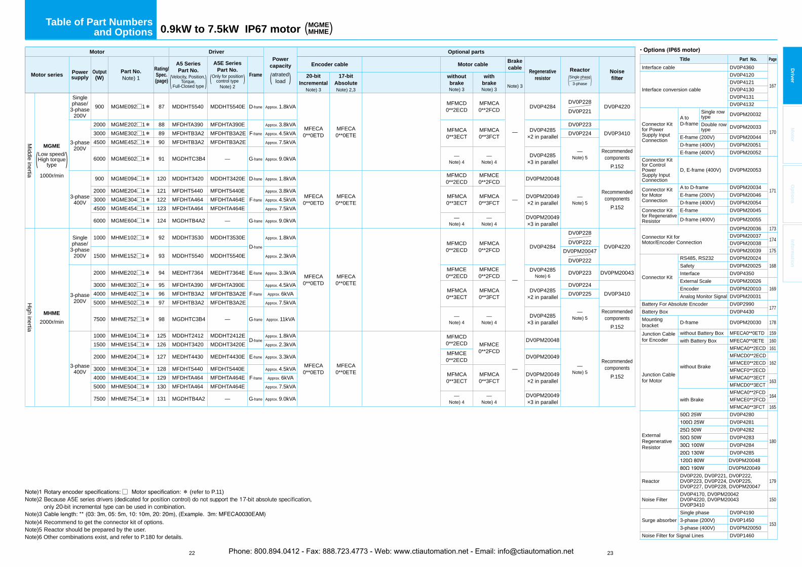
□ * (refer to P.11) Note)2 Because A5E series drivers (dedicated for position control) do not support the 17-bit absolute specification, only 20-bit incremental type can be used in combination.Note)3 Note)4 Recommend to get the connector kit of options.Note)5 Reactor should be prepared by the user.Note)6 Other combinations exist, and refer to P.180 for details.
Table of Part Numbersand Options 0.9kW to 7.5kW IP67 motor (MGME
MHME)
Title Part No. Page
Interface cable DV0P4360
167Interface conversion cable
DV0P4120DV0P4121DV0P4130DV0P4131DV0P4132
Connector Kitfor Power Supply Input Connection
A to D-frame
Single row type DV0PM20032
170Double row type DV0PM20033
E-frame (200V) DV0PM20044D-frame (400V) DV0PM20051E-frame (400V) DV0PM20052
Connector Kitfor Control PowerSupply Input Connection
D, E-frame (400V) DV0PM20053
171Connector Kitfor Motor Connection
A to D-frame DV0PM20034E-frame (200V) DV0PM20046D-frame (400V) DV0PM20054
Connector Kitfor Regenerative Resistor
E-frame DV0PM20045
D-frame (400V) DV0PM20055
Connector Kit for Motor/Encoder Connection
DV0PM20036 173DV0PM20037
174DV0PM20038DV0PM20039 175
Connector Kit
RS485, RS232 DV0PM20024168Safety DV0PM20025
Interface DV0P4350External Scale DV0PM20026
169Encoder DV0PM20010Analog Monitor Signal DV0PM20031
Battery For Absolute Encoder DV0P2990177
Battery Box DV0P4430Mountingbracket D-frame DV0PM20030 178
Junction Cable for Encoder
without Battery Box MFECA0**0ETD 159with Battery Box MFECA0**0ETE 160
Junction Cable for Motor
without Brake
MFMCA0**2ECD 161MFMCD0**2ECD
162MFMCE0**2ECDMFMCF0**2ECDMFMCA0**3ECT
163MFMCD0**3ECT
with BrakeMFMCA0**2FCD
164MFMCE0**2FCDMFMCA0**3FCT 165
ExternalRegenerativeResistor
DV0P4280
180
DV0P4281DV0P4282DV0P4283DV0P4284DV0P4285DV0PM20048DV0PM20049
ReactorDV0P220, DV0P221, DV0P222, DV0P223, DV0P224, DV0P225, DV0P227, DV0P228, DV0PM20047
179
Noise FilterDV0P4170, DV0PM20042DV0P4220, DV0PM20043DV0P3410
150
Surge absorberSingle phase DV0P4190
1533-phase (200V) DV0P14503-phase (400V) DV0PM20050
Noise Filter for Signal Lines DV0P1460
Phone: 800.894.0412 - Fax: 888.723.4773 - Web: www.ctiautomation.net - Email: [email protected]

24 25
Driver
Mo
tor
Op
tion
sIn
form
ation
A5 series Velocity, Position, Torque, (Full-Closed type )
Function
Position control
Control input (1) Deviation counter clear (2) Command pulse inhibitation (3) Electric gear (4) Damping control switching etc.
Control output Positioning complete (In-position) etc.
Pulseinput
Max. command pulse frequency
Input pulse signal formatDifferential input ((1) Positive and Negative direction, (2) A and B-phase, (3) Command and direction)
Electronic gear (Division/Multiplication of command pulse)
1/1000 to 1000 times
Analoginput
Torque limit command input Individual torque limit for both positive and negative direction is enabled.Torque feed forward input Analog voltage can be used as torque feed forward input.
Instantaneous Speed Observer AvailableDamping Control Available
Velocity control
Control input(1) Selection of internal velocity setup 1 (2) Selection of internal velocity setup 2(3) Selection of internal velocity setup 3 (4) Speed zero clamp etc.
Control output Speed arrival etc.
Analoginput
Velocity command inputSpeed command input can be provided by means of analog voltage.Parameters are used for scale setting and command polarity. (6V/Rated rotational speed Default)
Torque limit command input Individual torque limit for both positive and negative direction is enabled.Torque feed forward input Analog voltage can be used as torque feed forward input.
Internal velocity command Switching the internal 8speed is enabled by command input.
Soft-start/down function Individual setup of acceleration and deceleration is enabled, with 0 to 10s/1000r/min. Sigmoid acceleration/deceleration is also enabled.
Zero-speed clamp Speed zero clamp input is enabled.Instantaneous Speed Observer Available
Available
Torque control
Control input Speed zero clamp, Torque command sign input etc.Control output Speed arrival etc.
Analoginput Torque command input
Speed command input can be provided by means of analog voltage.Parameters are used for scale setting and command polarity. (3V/rated torque Default)
Speed limit function Speed limit value with parameter t is enabled.Full-closed control
Control input(1) Deviation counter clear (2) Command pulse inhibition (3) Command dividing gradual increase switching (4) Damping control switching etc.
Control output Full-closed positioning complete etc.
Pulseinput
Max. command pulse frequencyInput pulse signal format Differential inputElectronic gear (Division/Multiplication of command pulse)
1/1000 to 1000 times
Analoginput
Torque limit command input Individual torque limit for both positive and negative direction is enabled.Torque feed forward input Analog voltage can be used as torque feed forward input.
Setup range of division/multiplication of feedback scale 1/40 to 160 times
Com
mon
Auto tuningThe load inertia is identified in real time by the driving state of the motor operating according to the command given by the controlling device and set up support software “PANATERM”. The gain is set automatically in accordance with the rigidity setting.
Division of encoder feedback pulse Set up of any value is enabled (encoder pulses count is the max.).
Protectivefunction
Hard error Over-voltage, under-voltage, over-speed, over-load, over-heat, over-current and encoder error etc.
Soft error Excess position deviation, command pulse division error, EEPROM error etc.
Traceability of alarm data The alarm data history can be referred to.
Input power
100VMain circuit Single phase, 100 to 120V +10% 50/60Hz–15%
Control circuit Single phase, 100 to 120V +10% 50/60Hz–15%
200V
Maincircuit
A to D-frame Single/3-phase, 200 to 240V +10% 50/60Hz–15%
E to H-frame 3-phase, 200 to 230V +10% 50/60Hz–15%
Controlcircuit
A to D-frame Single phase, 200 to 240V +10% 50/60Hz–15%
E to H-frame Single phase, 200 to 230V +10% 50/60Hz–15%
400V
Maincircuit
D to H-frame 3-phase, 380 to 480V +10% 50/60Hz–15%
Controlcircuit
D to H-frame DC 24V ± 15%
Environment
temperature*1)
humidity *1)
Altitude Lower than 1000m
Vibration 5.88m/s2 or less, 10 to 60Hz (No continuous use at resonance frequency)
Control method
Encoder feedback 17-bit (131072 resolution) absolute encoder, 7-wire serial20-bit (1048576 resolution) incremental encoder, 5-wire serial
Feedback scale feedback
A/Bphase A/B phase, initialization signal defferential input.
serial Mitutoyo Corporation Magnescale Co., Ltd. MicroE SystemsRenishaw KK, Fagor Automation S.Coop
Parallel I/O connector
Control signalInput General purpose 10 inputs
The function of general-purpose input is selected by parameters.
Output General purpose 6 outputsThe function of general-purpose output is selected by parameters.
Analog signalInput
Output
Pulse signalInput 2 inputs (Photo-coupler input, Line receiver input)
Output 、
Communicationfunction
USB Connection with PC etc.
RS232
RS485
Safety function Used for functional safety.
Front panel (1) 5 keys (2) LED (6-digit) (3) Analog monitor output (2ch) (4) Digital monitor output (1ch)
Regeneration no built-in regenerative resistor (external resistor only)
Built-in regenerative resistor (external resistor is also enabled.)
Dynamic brake
Control mode
Switching among the following 7 mode is enabled, (1) Position control (2) Velocity control (3) Toque control(4) Position/Velocity control (5) Position/Torque control(6) Velocity/Torque control (7) Full-closed control
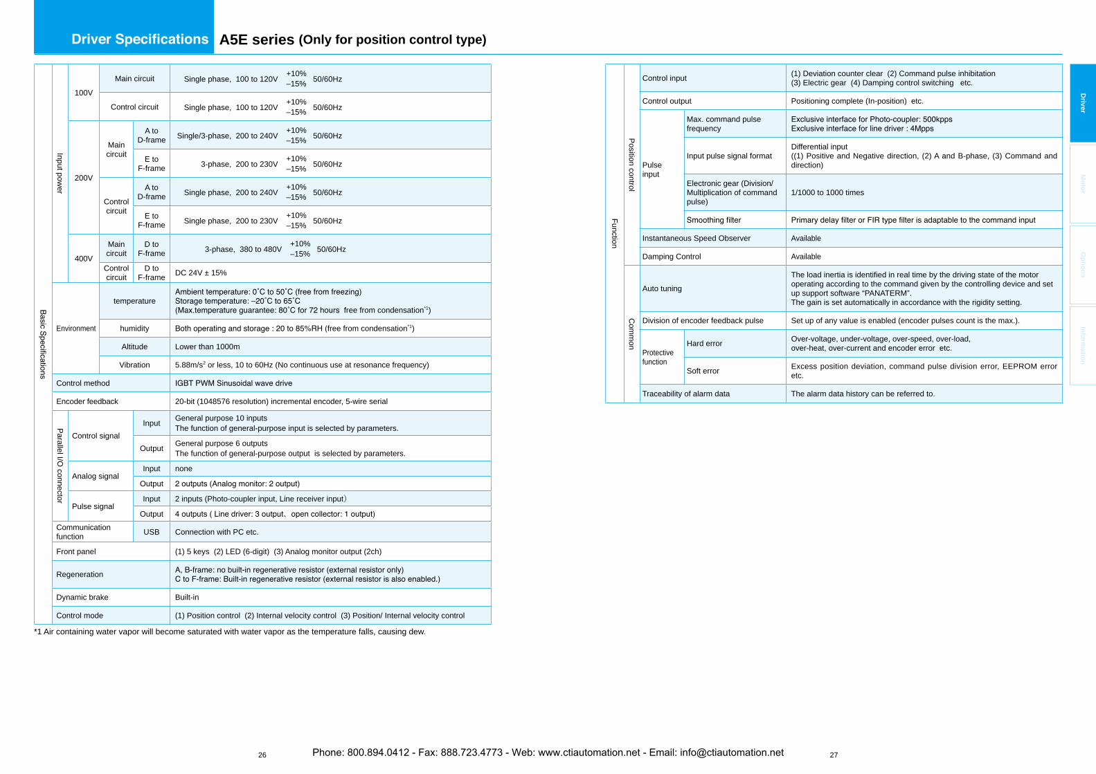
*1 Air containing water vapor will become saturated with water vapor as the temperature falls, causing dew.
Phone: 800.894.0412 - Fax: 888.723.4773 - Web: www.ctiautomation.net - Email: [email protected]
26 27
Driver
Mo
tor
Op
tion
sIn
form
ation
A5E series (Only for position control type)
Input power
100V
Main circuit Single phase, 100 to 120V +10% 50/60Hz–15%
Control circuit Single phase, 100 to 120V +10% 50/60Hz–15%
200V
Maincircuit
A to D-frame Single/3-phase, 200 to 240V +10% 50/60Hz–15%
E to F-frame 3-phase, 200 to 230V +10% 50/60Hz–15%
Controlcircuit
A to D-frame Single phase, 200 to 240V +10% 50/60Hz–15%
E to F-frame Single phase, 200 to 230V +10% 50/60Hz–15%
400V
Maincircuit
D to F-frame 3-phase, 380 to 480V +10% 50/60Hz–15%
Controlcircuit
D to F-frame DC 24V ± 15%
Environment
temperaturefree from condensation*1)
humidity free from condensation*1)
Altitude Lower than 1000m
Vibration 5.88m/s2 or less, 10 to 60Hz (No continuous use at resonance frequency)
Control method
Encoder feedback 20-bit (1048576 resolution) incremental encoder, 5-wire serial
Parallel I/O connector
Control signalInput General purpose 10 inputs
The function of general-purpose input is selected by parameters.
Output General purpose 6 outputsThe function of general-purpose output is selected by parameters.
Analog signalInput none
Output
Pulse signalInput 2 inputs (Photo-coupler input, Line receiver input)
Output 、Communicationfunction USB Connection with PC etc.
Front panel (1) 5 keys (2) LED (6-digit) (3) Analog monitor output (2ch)
Regeneration
Dynamic brake Built-in
Control mode (1) Position control (2) Internal velocity control (3) Position/ Internal velocity control
*1 Air containing water vapor will become saturated with water vapor as the temperature falls, causing dew.
Function
Position control
Control input (1) Deviation counter clear (2) Command pulse inhibitation (3) Electric gear (4) Damping control switching etc.
Control output Positioning complete (In-position) etc.
Pulseinput
Max. command pulse frequency
Input pulse signal formatDifferential input ((1) Positive and Negative direction, (2) A and B-phase, (3) Command and direction)
Electronic gear (Division/Multiplication of command pulse)
1/1000 to 1000 times
Instantaneous Speed Observer Available
Damping Control Available
Com
mon
Auto tuningThe load inertia is identified in real time by the driving state of the motor operating according to the command given by the controlling device and set up support software “PANATERM”.The gain is set automatically in accordance with the rigidity setting.
Division of encoder feedback pulse Set up of any value is enabled (encoder pulses count is the max.).
Protectivefunction
Hard error Over-voltage, under-voltage, over-speed, over-load, over-heat, over-current and encoder error etc.
Soft error Excess position deviation, command pulse division error, EEPROM error etc.
Traceability of alarm data The alarm data history can be referred to.
Phone: 800.894.0412 - Fax: 888.723.4773 - Web: www.ctiautomation.net - Email: [email protected]
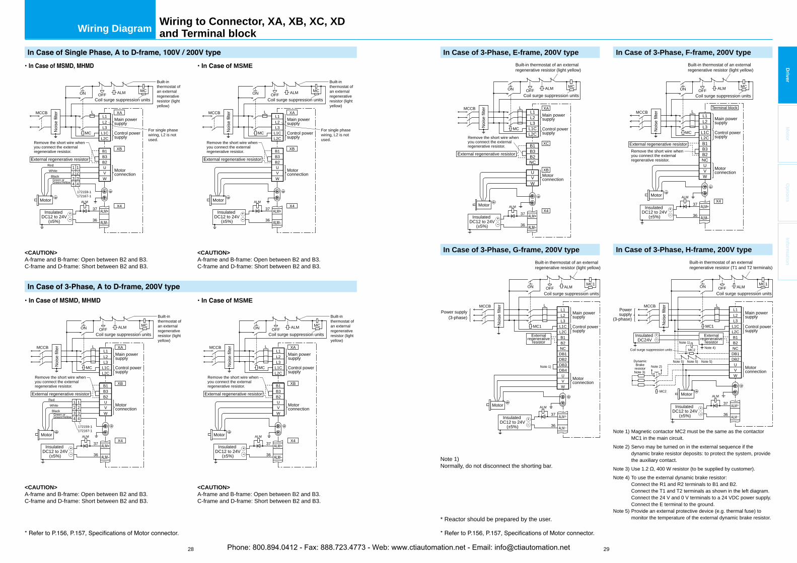
28 29
Driver
Mo
tor
Op
tion
sIn
form
ation
Wiring Diagram
Noi
se fi
lter
Main powersupply
Control powersupply
Motor
37 ALM+
L2L3
L1CL2C
B1
MC
MCCB
ALMOFF
B3B2UVW
L1
Coil surge suppression units
Motorconnection
172159-1172167-1
XA
XB
X4
36
L
ON MC
ALM
Built-inthermostat of an external regenerativeresistor (light yellow)
For single phase wiring, L2 is not used.
External regenerative resistor
Remove the short wire whenyou connect the external regenerative resistor.
Remove the short wire whenyou connect the external regenerative resistor.
Remove the short wire whenyou connect the external regenerative resistor.
<CAUTION>A-frame and B-frame: Open between B2 and B3.C-frame and D-frame: Short between B2 and B3.
1RedWhite
BlackGreen or Green/Yellow
234
1234
External regenerative resistor
Noi
se fi
lter
Main powersupply
Control powersupply
37 ALM+
L2L3
L1CL2C
B1
MC
MCCB
ALMOFF
B3B2UVW
L1
Coil surge suppression units
Motorconnection
Remove the short wire whenyou connect the external regenerative resistor.
XA
XB
X4
36
L
ON MC
ALM
<CAUTION>A-frame and B-frame: Open between B2 and B3.C-frame and D-frame: Short between B2 and B3.
Built-inthermostat of an external regenerativeresistor (light yellow)
Motor
172159-1172167-1
1RedWhite
BlackGreen or Green/Yellow
234
1234
External regenerative resistor
Noi
se fi
lter
Main powersupply
Control powersupply
Motor
37 ALM+
L2L3
L1CL2C
B1
MC
MCCB
ALMOFF
B3B2UVW
L1
Coil surge suppression units
Motorconnection
XA
XB
X4
36
L
ON MC
ALM
Built-inthermostat of an external regenerativeresistor (light yellow)
For single phase wiring, L2 is not used.
Noi
se fi
lter
Main powersupply
Control powersupply
37 ALM+
L2L3
L1CL2C
B1
MC
MCCB
ALMOFF
B3B2UVW
L1
Coil surge suppression units
Motorconnection
External regenerative resistor
XA
XB
X4
36
L
ON MC
ALM
<CAUTION>A-frame and B-frame: Open between B2 and B3.C-frame and D-frame: Short between B2 and B3.
<CAUTION>A-frame and B-frame: Open between B2 and B3.C-frame and D-frame: Short between B2 and B3.
Built-inthermostat of an external regenerativeresistor (light yellow)
MSME
MSME
Motor
InsulatedDC12 to 24V
(±5%)+ Insulated
DC12 to 24V(±5%)
+
InsulatedDC12 to 24V
(±5%)+ Insulated
DC12 to 24V(±5%)
+
Note 1) Normally, do not disconnect the shorting bar.
In Case of 3-Phase, E-frame, 200V type
In Case of 3-Phase, G-frame, 200V type In Case of 3-Phase, H-frame, 200V type
Noi
se fi
lter
External regenerative resistor
Motor
37 ALM+
L2L3
L1CL2C
B1
MC
MCCB
ALMOFF
B3B2NC
UVW
L1
Coil surge suppression units
XA
XC
XB
X4
36
L
ON MC
ALM
Main powersupply
Control powersupply
Motorconnection
Remove the short wire whenyou connect the external regenerative resistor.
Noi
se fi
lter
Main powersupply
Control powersupply
Motor
37 ALM+
L2L3
L1CL2C
MC1
L1
ALM-
MCCB
Motorconnection
36
L
ON
ALM
B1B2NCDB1DB2DB3DB4
UVW
ALMOFFCoil surge suppression units
Built-in thermostat of an externalregenerative resistor (light yellow)
Built-in thermostat of an externalregenerative resistor (light yellow)
In Case of 3-Phase, F-frame, 200V type
Remove the short wire whenyou connect the external regenerative resistor.
Motor
37 ALM+
L2L3
L1CL2C
MC
MCCBL1
X4
Terminal block
36
L
ON
ALM
B1B3B2NCUVW
ALMOFFMC
Noi
se fi
lter
External regenerative resistor
Main powersupply
Control powersupply
Motorconnection
Coil surge suppression units
Built-in thermostat of an externalregenerative resistor (light yellow)
Externalregenerative
resistor
Power supply(3-phase)
MC1
Note 1) Magnetic contactor MC2 must be the same as the contactor MC1 in the main circuit.
Note 2) Servo may be turned on in the external sequence if the dynamic brake resistor deposits: to protect the system, provide the auxiliary contact.
Note 3) Use 1.2 , 400 W resistor (to be supplied by customer).Note 4) To use the external dynamic brake resistor: Connect the R1 and R2 terminals to B1 and B2. Connect the T1 and T2 terminals as shown in the left diagram. Connect the 24 V and 0 V terminals to a 24 VDC power supply. Connect the E terminal to the ground.Note 5) Provide an external protective device (e.g. thermal fuse) to
monitor the temperature of the external dynamic brake resistor.
Noi
se fi
lter
Main powersupply
Control powersupply
Motor
37 ALM+
L2L3
L1CL2C
MC1
L1
ALM-
MCCB
Motorconnection
36
L
ON
ALM
B1B2
DB1NC
DB2UVW
ALMOFFCoil surge suppression units
Powersupply
(3-phase)
MC1
Note 1)
Note 1)
Note 4)
Note 5) Note 5) Note 5)
MC2Coil surge suppression units
Externalregenerative
resistor
DynamicBrake
resistorNote 3)
Note 2)
MC2
Built-in thermostat of an externalregenerative resistor (T1 and T2 terminals)
InsulatedDC12 to 24V
(±5%)+
InsulatedDC12 to 24V
(±5%)+
InsulatedDC12 to 24V
(±5%)+
InsulatedDC12 to 24V
(±5%)+
InsulatedDC24V
+
Wiring to Connector, XA, XB, XC, XDand Terminal block
* Reactor should be prepared by the user.
Phone: 800.894.0412 - Fax: 888.723.4773 - Web: www.ctiautomation.net - Email: [email protected]
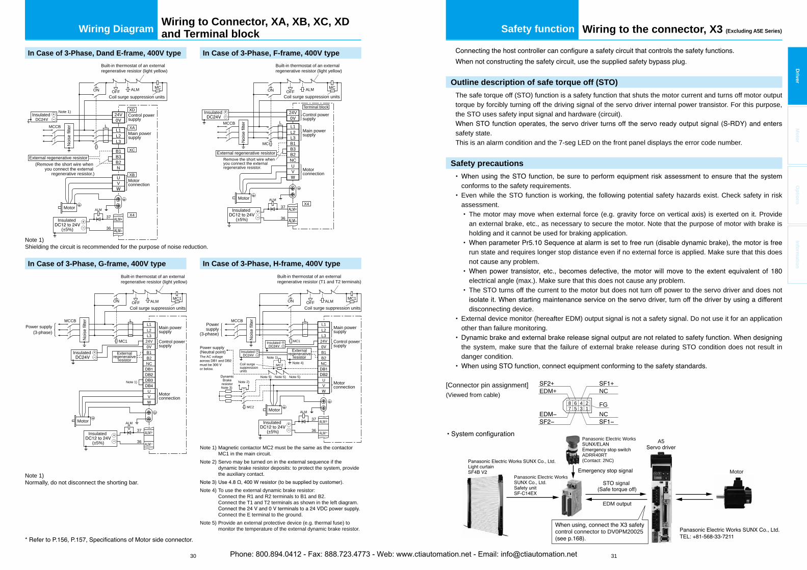
30 31
Driver
Mo
tor
Op
tion
sIn
form
ation
Wiring Diagram Safety function Wiring to the connector, X3 (Excluding A5E Series)
Outline description of safe torque off (STO)
The safe torque off (STO) function is a safety function that shuts the motor current and turns off motor output torque by forcibly turning off the driving signal of the servo driver internal power transistor. For this purpose, the STO uses safety input signal and hardware (circuit).
safety state.This is an alarm condition and the 7-seg LED on the front panel displays the error code number.
Safety precautions
conforms to the safety requirements.Even while the STO function is working, the following potential safety hazards exist. Check safety in risk assessment.
The motor may move when external force (e.g. gravity force on vertical axis) is exerted on it. Provide an external brake, etc., as necessary to secure the motor. Note that the purpose of motor with brake is holding and it cannot be used for braking application.
run state and requires longer stop distance even if no external force is applied. Make sure that this does not cause any problem.
electrical angle (max.). Make sure that this does not cause any problem.The STO turns off the current to the motor but does not turn off power to the servo driver and does not
disconnecting device.External device monitor (hereafter EDM) output signal is not a safety signal. Do not use it for an application other than failure monitoring.
the system, make sure that the failure of external brake release during STO condition does not result in danger condition.
[Connector pin assignment](Viewed from cable)
8 6 4 27 5 3 1
NCFG
NC++
EDM+
A5
MotorPanasonic Electric Works
Panasonic Electric Works
ADRR40RT(Contact: 2NC)
EDM
signal
control connector to DV0PM20025
In Case of 3-Phase, Dand E-frame, 400V type
In Case of 3-Phase, G-frame, 400V type In Case of 3-Phase, H-frame, 400V type
Built-in thermostat of an externalregenerative resistor (T1 and T2 terminals)
In Case of 3-Phase, F-frame, 400V type
Built-in thermostat of an externalregenerative resistor (light yellow)
Built-in thermostat of an externalregenerative resistor (light yellow)
Note 1) Magnetic contactor MC2 must be the same as the contactor MC1 in the main circuit.
Note 2) Servo may be turned on in the external sequence if the dynamic brake resistor deposits: to protect the system, provide the auxiliary contact.
Note 4) To use the external dynamic brake resistor: Connect the R1 and R2 terminals to B1 and B2. Connect the T1 and T2 terminals as shown in the left diagram.
Connect the E terminal to the ground.Note 5) Provide an external protective device (e.g. thermal fuse) to
monitor the temperature of the external dynamic brake resistor.
Noi
se fi
lter
Main powersupply
Control powersupply
Motor
37 ALM+
L2L3
24VMC1
L1
ALM-
MCCB
Motorconnection
36
L
ON
ALM
B1B2NC
UV
ALMOFFCoil surge suppression units
Powersupply
(3-phase)
MC1
Note 1) Note 4)
Note 5) Note 5) Note 5)
MC2Coil surge suppressionunits
Externalregenerative
resistor
BrakeresistorNote 3)
Note 2)
MC2
Noi
se fi
lter
External regenerative resistor
Motor
37 ALM+
B1MC
MCCB
ALMOFF
B3B2NCUV
24V
L2L3
L1
Coil surge suppression units
X4
36
L
ON MC
ALM
Main powersupply
Control powersupply
Motorconnection
Remove the short wire whenyou connect the external regenerative resistor.
Terminal block
The AC voltage
or below.
Power supply(Neutral point)
Note 1) Normally, do not disconnect the shorting bar.
Noi
se fi
lter
Main powersupply
Control powersupply
Motor
37 ALM+
L2L3
24VMC1
L1
ALM-
MCCB
Motorconnection
36
L
ON
ALM
B1B2NC
UV
ALMOFFCoil surge suppression units
Built-in thermostat of an externalregenerative resistor (light yellow)
Externalregenerative
resistor
Power supply(3-phase)
MC1
Note 1)
Insulated
(±5%)+
Insulated
(±5%)+
Insulated
(±5%)+
Insulated +
Insulated +
Insulated +
Insulated +
Motor
37 ALM+
L2L3
MCCBL1
24V
XC
XB
XA
X4
36
L
ON
ALM
B1B3B2N
UV
ALMOFFMC
External regenerative resistor(Remove the short wire when
you connect the external regenerative resistor.)
Main powersupply
Control powersupply
Motorconnection
Noi
se fi
lter
Coil surge suppression units
Insulated
Insulated
(±5%)+
+ Note 1)
Note 1) Shielding the circuit is recommended for the purpose of noise reduction.
Wiring to Connector, XA, XB, XC, XDand Terminal block
Phone: 800.894.0412 - Fax: 888.723.4773 - Web: www.ctiautomation.net - Email: [email protected]
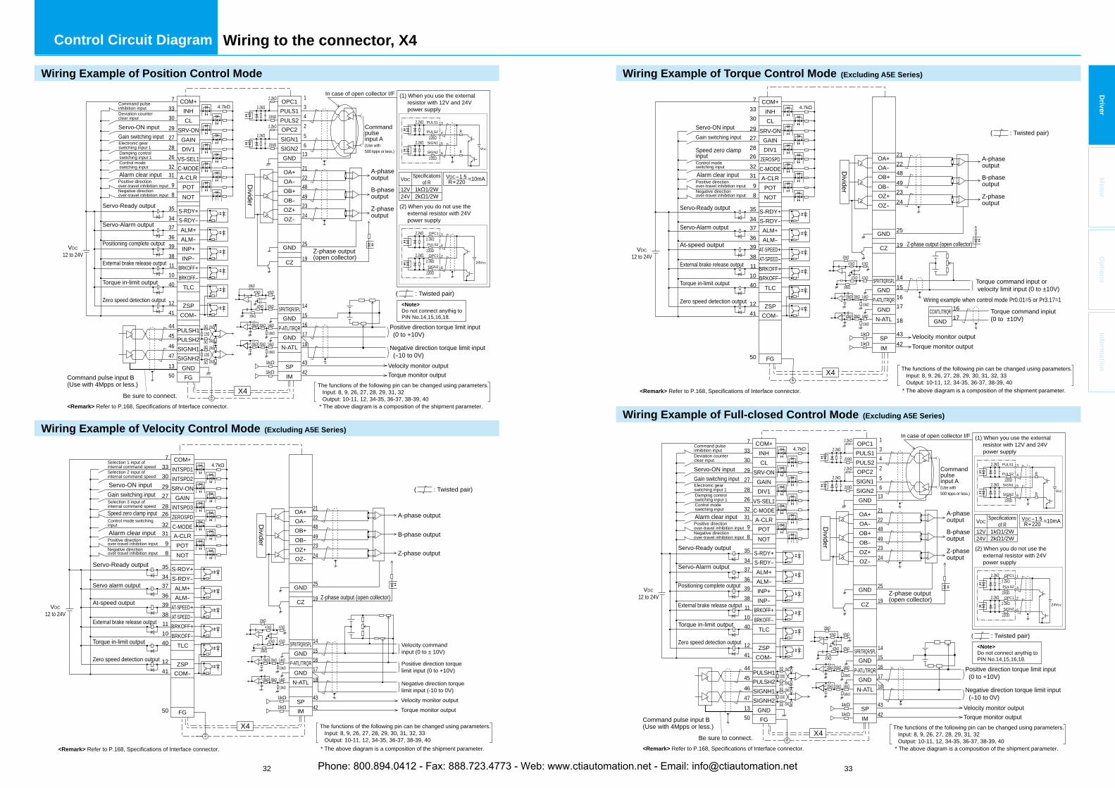
32 33
Driver
Mo
tor
Op
tion
sIn
form
ation
Control Circuit Diagram Wiring to the connector, X4
2.2k
2.2k
2.2k
2.2k
14151617
43
18
42
In case of open collector I/F7 COM+
PULS2
SIGN1SIGN2GND
OA+OA-OB+OB-OZ+OZ-
GND
CZ
SPR/TRQR/SPLGND
P-ATL/TRQRGNDN-ATL
SPIM
431
256
13
212248
24
25
19
4923
1k
1k
PULS1
OPC2
OPC1INHCL
SRV-ONGAINDIV1
VS-SEL1C-MODEA-CLRPOTNOT
S-RDY+S-RDY-ALM+
INP+
BRKOFF+BRKOFF-
TLC
VDC12 to 24V
ZSPCOM-
SIGNH1SIGNH2
PULSH1PULSH2
GNDFG
INP-
ALM-
3330292728
323198
353437363938111040
1241
4445
1350
26
Z-phase output(open collector)
3PULS1
4PULS2
X4
4647
14k
10k
20k20k
14k
10k
20k20k
47k
47k47k
47k
20k
20k
+–
+–
–
The functions of the following pin can be changed using parameters. Input: 8, 9, 26, 27, 28, 29, 31, 32 Output: 10-11, 12, 34-35, 36-37, 38-39, 40
<Note>Do not connect anythig to PIN No.14,15,16,18.
* The above diagram is a composition of the shipment parameter.<Remark> Refer to P.168, Specifications of Interface connector.
20k2k
2k 20k120
20k2k
2k 20k120
220
VDC
R
5SIGN1
6SIGN2220
R
1OPC1
4PULS2220
24VDC
2OPC1
6SIGN2220
2.2k
2.2k
(1) When you use the external resistor with 12V and 24V power supply
(2) When you do not use the external resistor with 24V power supply
Positive direction torque limit input(0 to +10V)
Negative direction torque limit input (-10 to 0V)
Velocity monitor outputTorque monitor output
Commandpulseinput A(Use with500 kpps or less.)
Divider
A-phaseoutput
B-phaseoutput
Z-phaseoutput
Command pulse input B(Use with 4Mpps or less.)
Be sure to connect.
VDC
12V24V
Specificationsof R
1k 1/2W2k 1/2W
VDC-1.5R+220 =10mA.
.
Servo-ON inputGain switching inputElectronic gear switching input 1
Control mode switching input
Damping control switching input 1
Alarm clear inputPositive directionover-travel inhibition inputNegative direction over-travel inhibition input
Servo-Ready output
Servo-Alarm output
Positioning complete output
External brake release output
Torque in-limit output
Zero speed detection output
Deviation counter clear input
Command pulse inhibition input
( : Twisted pair)
4.7k
220
2.2k
2.2k
220
2.2k
2.2k
7 COM+
OA+OA-OB+OB-OZ+OZ-
GND
CZ
SPR/TRQR/SPLGND
P-ATL/TRQRGNDN-ATL
SPIM
212248
24
25
19
4923
1k
1k
INTSPD1INTSPD2SRV-ON
GAININTSPD3ZEROSPDC-MODEA-CLRPOTNOT
S-RDY+S-RDY-ALM+
BRKOFF+BRKOFF-
TLC
VDC12 to 24V
ZSPCOM-
FG
ALM-
33302927
323198
353437363938111040
1241
50
28
14151617
18
4342
26
14k
10k
20k20k
14k
10k
20k20k
47k
47k47k
47k
20k
20k
X4
A-phase output
B-phase output
Z-phase output
Z-phase output (open collector)
Velocity command input (0 to ± 10V)
Positive direction torque limit input (0 to +10V)
Negative direction torque limit input (-10 to 0V)Velocity monitor outputTorque monitor output
Servo-ON inputGain switching input
Alarm clear input
Speed zero clamp input
Selection 1 input of internal command speed Selection 2 input of internal command speed
Selection 3 input ofinternal command speed
Control mode switching input
Positive directionover-travel inhibition inputNegative direction over-travel inhibition input
Servo-Ready output
Servo alarm output
At-speed output
Torque in-limit output
Zero speed detection output
Divider
The functions of the following pin can be changed using parameters. Input: 8, 9, 26, 27, 28, 29, 30, 31, 32, 33 Output: 10-11, 12, 34-35, 36-37, 38-39, 40
+–
+–
+–
AT-SPEED+AT-SPEED-
( : Twisted pair)
4.7k
External brake release output
* The above diagram is a composition of the shipment parameter.<Remark> Refer to P.168, Specifications of Interface connector.
Wiring Example of Velocity Control Mode (Excluding A5E Series)
Wiring Example of Position Control Mode
Wiring Example of Full-closed Control Mode (Excluding A5E Series)
Wiring Example of Torque Control Mode (Excluding A5E Series)
2.2k
2.2k
2.2k
2.2k
14151617
43
18
42
In case of open collector I/F7 COM+
PULS2
SIGN1SIGN2GND
OA+OA-OB+OB-OZ+OZ-
GND
CZ
SPR/TRQR/SPLGND
P-ATL/TRQRGND
N-ATL
SPIM
431
256
13
212248
24
25
19
4923
1k
1k
PULS1
OPC2
OPC1INHCL
SRV-ONGAINDIV1
VS-SEL1C-MODEA-CLRPOTNOT
S-RDY+S-RDY-ALM+
INP+
BRKOFF+BRKOFF-
TLC
VDC12 to 24V
ZSPCOM-
SIGNH1SIGNH2
PULSH1PULSH2
GNDFG
INP-
ALM-
3330292728
323198
353437363938111040
1241
4445
1350
26
Z-phase output(open collector)
3PULS1
4PULS2
X4
4647
14k
10k
20k20k
14k
10k
20k20k
47k
47k47k
47k
20k
20k
+–
+–
–
The functions of the following pin can be changed using parameters. Input: 8, 9, 26, 27, 28, 29, 31, 32 Output: 10-11, 12, 34-35, 36-37, 38-39, 40
<Note>Do not connect anythig to PIN No.14,15,16,18.
* The above diagram is a composition of the shipment parameter.<Remark> Refer to P.168, Specifications of Interface connector.
20k2k
2k 20k120
20k2k
2k 20k120
220
VDC
R
5SIGN1
6SIGN2220
R
1OPC1
4PULS2220
24VDC
2OPC1
6SIGN2220
2.2k
2.2k
(1) When you use the external resistor with 12V and 24V power supply
(2) When you do not use the external resistor with 24V power supply
Positive direction torque limit input(0 to +10V)
Negative direction torque limit input (-10 to 0V)
Velocity monitor outputTorque monitor output
Commandpulseinput A(Use with500 kpps or less.)
Divider
A-phaseoutput
B-phaseoutput
Z-phaseoutput
Command pulse input B(Use with 4Mpps or less.)
Be sure to connect.
VDC
12V24V
Specificationsof R
1k 1/2W2k 1/2W
VDC-1.5R+220 =10mA.
.
Servo-ON inputGain switching inputElectronic gear switching input 1
Control mode switching input
Damping control switching input 1
Alarm clear inputPositive directionover-travel inhibition inputNegative direction over-travel inhibition input
Servo-Ready output
Servo-Alarm output
Positioning complete output
External brake release output
Torque in-limit output
Zero speed detection output
Deviation counter clear input
Command pulse inhibition input
( : Twisted pair)
4.7k
220
2.2k
2.2k
220
2.2k
2.2k
7 COM+
OA+OA-OB+OB-OZ+OZ-
GND
CZ
SPR/TRQR/SPLGND
P-ATL/TRQRGND
N-ATL
SPIM
212248
24
25
19
14151617
43
18
42
4923
14k
10k
20k20k
14k
10k
20k20k
47k
47k47k
47k
20k
20k
1k
1k
INHCL
SRV-ONGAINDIV1
ZEROSPDC-MODEA-CLRPOTNOT
S-RDY+S-RDY-ALM+
AT-SPEED+
BRKOFF+BRKOFF-
TLC
VDC12 to 24V
ZSPCOM-
FG
AT-SPEED-
ALM-
333029272826323198
353437363938111040
1241
50
Z-phase output (open collector)
X4 The functions of the following pin can be changed using parameters. Input: 8, 9, 26, 27, 28, 29, 30, 31, 32, 33 Output: 10-11, 12, 34-35, 36-37, 38-39, 40 * The above diagram is a composition of the shipment parameter.<Remark> Refer to P.168, Specifications of Interface connector.
Divider
A-phaseoutput
B-phaseoutput
Z-phaseoutput
Torque command input or velocity limit input (0 to ±10V)
Velocity monitor outputTorque monitor output
Wiring example when control mode Pr0.01=5 or Pr3.17=1
CCWTL/TRQRGND
1617
Torque command inpiut(0 to ±10V)
+–
+–
+–
Servo-ON inputGain switching input
Alarm clear input
Servo-Ready output
Servo-Alarm output
At-speed output
External brake release output
Torque in-limit output
Zero speed detection output
Speed zero clamp inputControl mode switching input
Positive directionover-travel inhibition inputNegative direction over-travel inhibition input
( : Twisted pair)
4.7k
Phone: 800.894.0412 - Fax: 888.723.4773 - Web: www.ctiautomation.net - Email: [email protected]
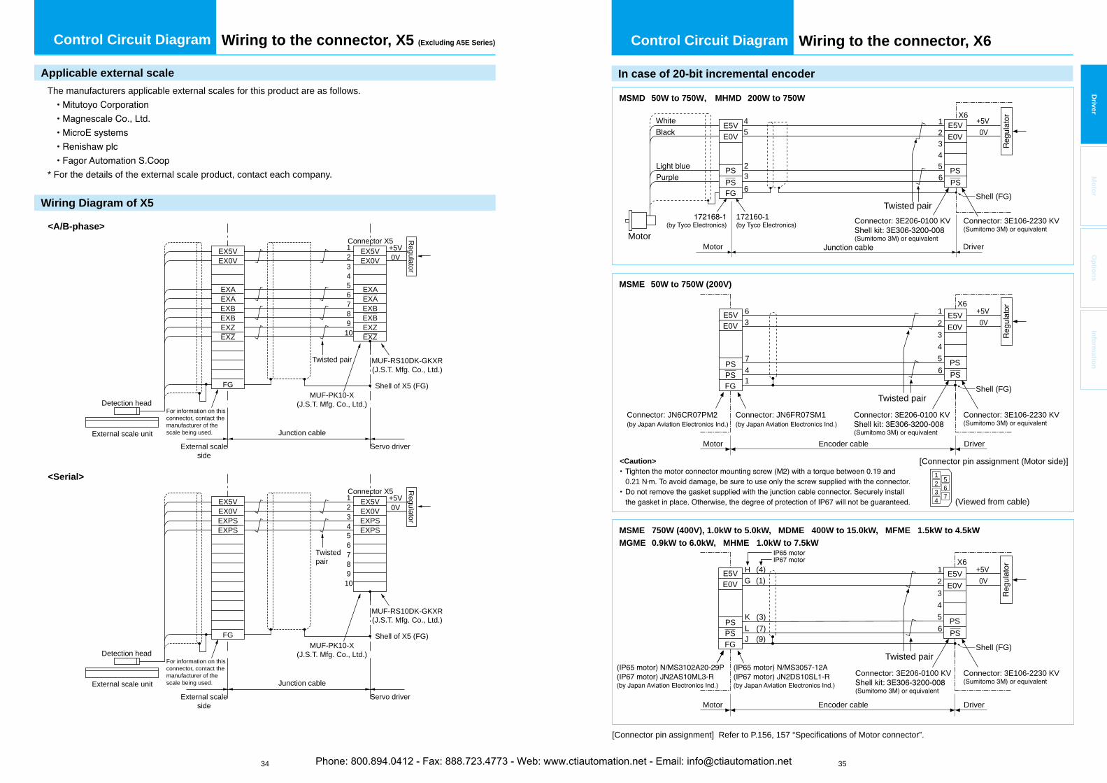
34 35
Driver
Mo
tor
Op
tion
sIn
form
ation
Wiring to the connector, X5 (Excluding A5E Series)Control Circuit Diagram
Applicable external scale
The manufacturers applicable external scales for this product are as follows.
* For the details of the external scale product, contact each company.
Wiring Diagram of X5
<Serial>
<A/B-phase>
External scaleside
External scale unit
Detection head
Junction cable
Servo driver
EX5VEX0V
EXAEXAEXBEXBEXZEXZ
EX5VEX0V
EXAEXAEXBEXBEXZEXZ
FG
Connector X512
+5V0V
345678910
Regulator
Shell of X5 (FG)
Twisted pair
External scaleside
External scale unit
Detection head
Junction cable
Servo driver
EX5VEX0VEXPSEXPS
EX5VEX0VEXPSEXPS
FG
Connector X512
+5V0V
345678910
Regulator
Shell of X5 (FG)
Twisted pair
MUF-PK10-X(J.S.T. Mfg. Co., Ltd.)
MUF-RS10DK-GKXR(J.S.T. Mfg. Co., Ltd.)
MUF-PK10-X(J.S.T. Mfg. Co., Ltd.)
MUF-RS10DK-GKXR(J.S.T. Mfg. Co., Ltd.)
For information on this connector, contact the manufacturer of the scale being used.
For information on this connector, contact the manufacturer of the scale being used.
Control Circuit Diagram Wiring to the connector, X6
In case of 20-bit incremental encoder
X6
Shell (FG)
X6
X6
[Connector pin assignment] Refer to P.156, 157 “Specifications of Motor connector”.
[Connector pin assignment (Motor side)]
(Viewed from cable)
2 51
3 6
4 7
Shell (FG)
Shell (FG)
Motor
123456
45
236
E5VE0V
E5VE0V
PSPS
FGPS PS
MSME 50W to 750W (200V)
MSMD 50W to 750W, MHMD 200W to 750W
MSME 750W (400V), 1.0kW to 5.0kW, MDME 400W to 15.0kW, MFME 1.5kW to 4.5kWMGME 0.9kW to 6.0kW, MHME 1.0kW to 7.5kW
+5V0V
123456
Twisted pair
Encoder cableMotor
Driver
Driver
E5VE0V
PSPS
PSPSFG
E5VE0V
+5V0V
123456
63
74
Twisted pair
Encoder cableMotor Driver
Motor
E5VE0V
PSPS
+5V0V
1
PSPSFG
E5VE0V
<Caution>
0.21 N
Connector: JN6FR07SM1Connector: JN6CR07PM2 Connector: 3E206-0100 KV Connector: 3E106-2230 KV
Connector: 3E206-0100 KV Connector: 3E106-2230 KV
Connector: 3E206-0100 KV Connector: 3E106-2230 KV
172160-1
White
Twisted pair
(4)(1)
(3)(7)( )
HG
K
J
Phone: 800.894.0412 - Fax: 888.723.4773 - Web: www.ctiautomation.net - Email: [email protected]
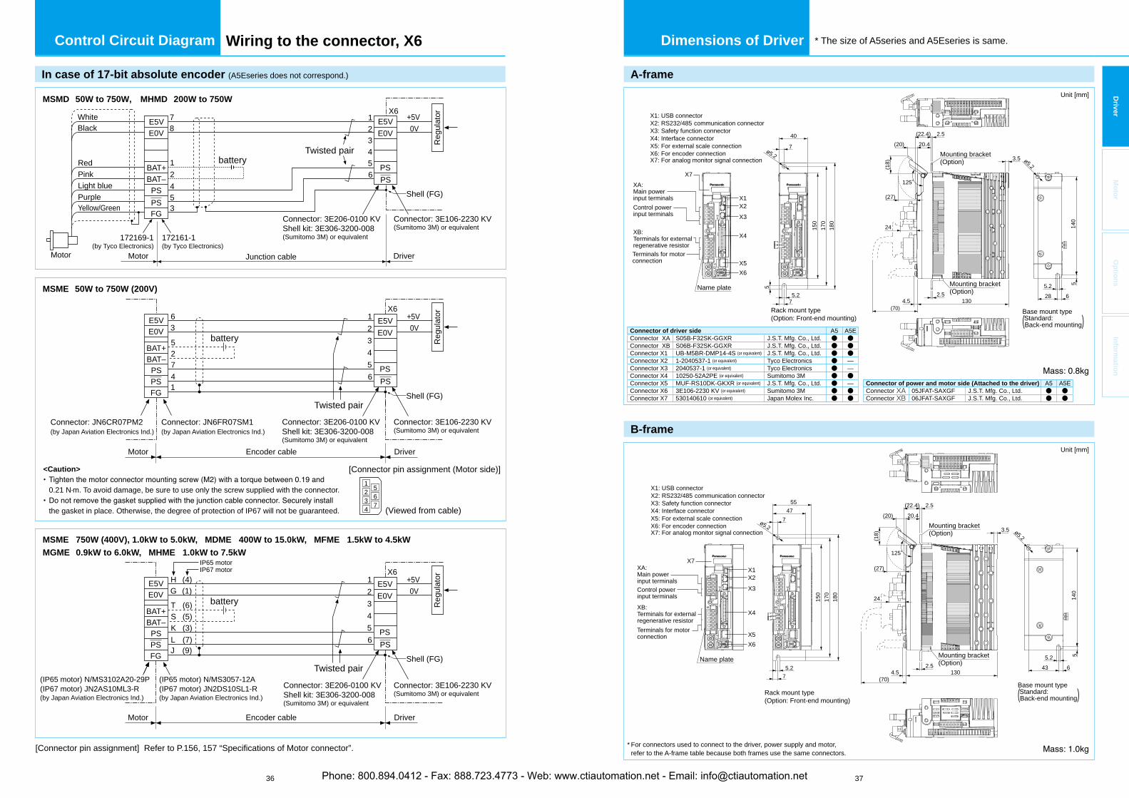
36 37
Driver
Mo
tor
Op
tion
sIn
form
ation
In case of 17-bit absolute encoder (A5Eseries does not correspond.)
MSMD 50W to 750W, MHMD 200W to 750W
Shell (FG)
X6
X6
Shell (FG)
X6
Shell (FG)
battery
battery
123456
78
12453
E5VE0V
E5VE0V
PS
PS
FGPS
PS
Connector: JN6FR07SM1(by Japan Aviation Electronics Ind.)
Connector: JN6CR07PM2(by Japan Aviation Electronics Ind.)
+5V
Encoder cableMotor Driver
Reg
ulat
or
+5V
Reg
ulat
or
0V123456
Twisted pair
Encoder cableMotor Driver
E5VE0V
PSPS
PSBAT–BAT+
PSFG
E5VE0V
0V123456
63
725
4
Twisted pair
E5VE0V
PSPS
1
PSBAT–BAT+
PSFG
E5VE0V
Motor Driver
0V
Twisted pair
172161-1(by Tyco Electronics)
172169-1(by Tyco Electronics)
BAT+BAT–
Motor
Black
PurpleYellow/Green
White
Light bluePinkRed battery
+5V
Reg
ulat
or
Junction cable
Connector: 3E206-0100 KVShell kit: 3E306-3200-008(Sumitomo 3M) or equivalent
Connector: 3E106-2230 KV(Sumitomo 3M) or equivalent
Connector: 3E206-0100 KVShell kit: 3E306-3200-008(Sumitomo 3M) or equivalent
Connector: 3E106-2230 KV(Sumitomo 3M) or equivalent
Connector: 3E206-0100 KVShell kit: 3E306-3200-008(Sumitomo 3M) or equivalent
Connector: 3E106-2230 KV(Sumitomo 3M) or equivalent
MSME 50W to 750W (200V)
MSME 750W (400V), 1.0kW to 5.0kW, MDME 400W to 15.0kW, MFME 1.5kW to 4.5kWMGME 0.9kW to 6.0kW, MHME 1.0kW to 7.5kW
[Connector pin assignment (Motor side)]
(Viewed from cable)
2 51
3 6
4 7
<Caution>
0.21 N m. To avoid damage, be sure to use only the screw supplied with the connector.
the gasket in place. Otherwise, the degree of protection of IP67 will not be guaranteed.
(IP65 motor) N/MS3102A20-29P(IP67 motor) JN2AS10ML3-R(by Japan Aviation Electronics Ind.)
(IP65 motor) N/MS3057-12A(IP67 motor) JN2DS10SL1-R(by Japan Aviation Electronics Ind.)
(4)(1)
(3)(7)(9)
HIP67 motorIP65 motor
G
K(5)S(6)T
LJ
[Connector pin assignment] Refer to P.156, 157 “Specifications of Motor connector”.
Control Circuit Diagram Wiring to the connector, X6 Dimensions of Driver * The size of A5series and A5Eseries is same.
A-frame
40
5.228 6
5
7
75.2
5
180
170
150
ø5.2ø5.2
140
Rack mount type (Option: Front-end mounting)
Base mount type Standard:(Back-end mounting)
X1X2
X7
X3
X4
X5X6
Name plate
XA:Main powerinput terminals
XB:Terminals for externalregenerative resistor
Control powerinput terminals
Terminals for motorconnection
(18)
(22.4)
24
20.4(20)
(27)
125°
2.5
3.5
2.54.5 130
(70)
Mounting bracket(Option)
Mounting bracket(Option)
X1: USB connectorX2: RS232/485 communication connectorX3: Safety function connectorX4: Interface connectorX5: For external scale connectionX6: For encoder connectionX7: For analog monitor signal connection
B-frame
5547
5.243 6
5
7
75.2
180
170
150
ø5.2ø5.2
140
Name plate
Rack mount type (Option: Front-end mounting)
Base mount type Standard:(Back-end mounting)
X1X2X3
X4
X5X6
XA:Main powerinput terminals
XB:Terminals for externalregenerative resistor
Control powerinput terminals
Terminals for motorconnection
(18)
(22.4)
24
20.4(20)
(27)
125°
2.5
3.5
2.54.5 130
(70)
Mounting bracket(Option)
Mounting bracket(Option)
X1: USB connectorX2: RS232/485 communication connectorX3: Safety function connectorX4: Interface connectorX5: For external scale connectionX6: For encoder connectionX7: For analog monitor signal connection
X7
Unit [mm]
Unit [mm]
Connector of driver side A5 A5EConnector XA S05B-F32SK-GGXR J.S.T. Mfg. Co., Ltd. ● ●Connector XB S06B-F32SK-GGXR J.S.T. Mfg. Co., Ltd. ● ●Connector X1 UB-M5BR-DMP14-4S (or equivalent) J.S.T. Mfg. Co., Ltd. ● ●Connector X2 1-2040537-1 (or equivalent) Tyco Electronics ● —Connector X3 2040537-1 (or equivalent) Tyco Electronics ● —Connector X4 10250-52A2PE (or equivalent) Sumitomo 3M ● ●Connector X5 MUF-RS10DK-GKXR (or equivalent) J.S.T. Mfg. Co., Ltd. ● —Connector X6 3E106-2230 KV (or equivalent) Sumitomo 3M ● ●Connector X7 530140610 (or equivalent) Japan Molex Inc. ● ●
* For connectors used to connect to the driver, power supply and motor, refer to the A-frame table because both frames use the same connectors.
Connector of power and motor side (Attached to the driver) A5 A5EConnector XA 05JFAT-SAXGF J.S.T. Mfg. Co., Ltd. ● ●Connector XB 06JFAT-SAXGF J.S.T. Mfg. Co., Ltd. ● ●
Phone: 800.894.0412 - Fax: 888.723.4773 - Web: www.ctiautomation.net - Email: [email protected]
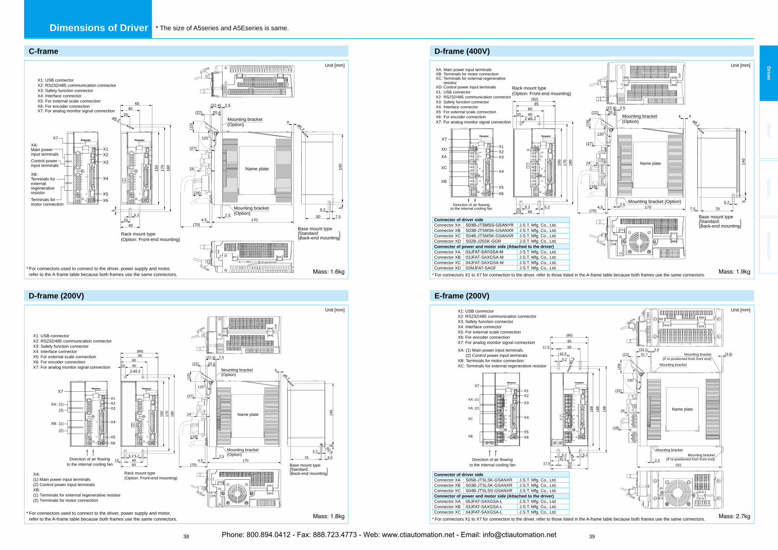
38 39
Driver
Mo
tor
Op
tion
sIn
form
ation
C-frame
6540
5.250 7.5
5
20
2040
5.2
5
180
170
150
ø5.2ø5.2
140
Rack mount type (Option: Front-end mounting)
Base mount type Standard:(Back-end mounting)
X1X2
X3
X4
X5X6
XA:Main powerinput terminals
XB:Terminals forexternalregenerativeresistor
Control powerinput terminals
Terminals for motor connection
Name plate
(15)
(22.4)
24
20.4(22)
(27)
120°
2.5
4
2.54.5 170
(70)
(18)
Mounting bracket(Option)
Mounting bracket(Option)
X1: USB connectorX2: RS232/485 communication connectorX3: Safety function connectorX4: Interface connectorX5: For external scale connectionX6: For encoder connectionX7: For analog monitor signal connection
X7
Unit [mm]
* For connectors used to connect to the driver, power supply and motor, refer to the A-frame table because both frames use the same connectors.
Dimensions of Driver * The size of A5series and A5Eseries is same.
D-frame (200V)
ø5.2
85(86)
60
5.270 8.5
5
4010
4060
105.25.2
180
170
150
R2.6
140
Rack mount type (Option: Front-end mounting)
Direction of air flowingto the internal cooling fan Base mount type
Standard:(Back-end mounting)
2-ø5.2
X1X2X3
X4
X5X6
X1: USB connectorX2: RS232/485 communication connectorX3: Safety function connectorX4: Interface connectorX5: For external scale connectionX6: For encoder connectionX7: For analog monitor signal connection
XA: (1) (2)
XB: (1)
(2)
XA:(1) Main power input terminals (2) Control power input terminalsXB:(1) Terminals for external regenerative resistor(2) Terminals for motor connection
Name plate
(15)
(22.4)
24
20.4(22)
(27)
120°
2.5
4
2.54.5 170
(70)
(18)
Mounting bracket(Option)
Mounting bracket(Option)
X7
Unit [mm]
* For connectors used to connect to the driver, power supply and motor, refer to the A-frame table because both frames use the same connectors.
D-frame (400V)
Direction of air flowingto the internal cooling fan
XA
XC
XD
XB
X1X2X3
X4
X5X6
XA: Main power input terminalsXB: Terminals for motor connectionXC: Terminals for external regenerative resistorXD: Control power input terminalsX1: USB connectorX2: RS232/485 communication connectorX3: Safety function connectorX4: Interface connectorX5: For external scale connectionX6: For encoder connectionX7: For analog monitor signal connection
85(92)
60
5.2707.5
5
4010
40105.25.2
180
170
150
ø5.2
140
2-ø5.2
Rack mount type (Option: Front-end mounting)
Base mount type Standard:(Back-end mounting)
4
Name plate
(15)
(22.4)
24
20.4(22)
(27)
120°
2.5
4
2.54.5 170(70)
(18)
Mounting bracket (Option)
Mounting bracket(Option)
X7
Unit [mm]
Connector of driver sideConnector XA J.S.T. Mfg. Co., Ltd.Connector XB S03B-JTSMSK-GSANXR J.S.T. Mfg. Co., Ltd.Connector XC S04B-JTSMSK-GSANXR J.S.T. Mfg. Co., Ltd.Connector XD S02B-J25SK-GGR J.S.T. Mfg. Co., Ltd.Connector of power and motor side (Attached to the driver)Connector XA J.S.T. Mfg. Co., Ltd.Connector XB 03JFAT-SAXGSA-M J.S.T. Mfg. Co., Ltd.Connector XC 04JFAT-SAXGSA-M J.S.T. Mfg. Co., Ltd.Connector XD 02MJFAT-SAGF J.S.T. Mfg. Co., Ltd.
* For connectors X1 to X7 for connection to the driver, refer to those listed in the A-frame table because both frames use the same connectors.
E-frame (200V)
855017.5
42.55.2
(86)
198
188
168
ø5.2
ø5.2
5.25.242.5
5085
17.5Direction of air flowing
to the internal cooling fan
X1X2
X3
X4
X5X6
2.5
(3.5)
Mounting bracketMounting bracket
(If re-positioned from front end)
Mounting bracket
Mounting bracket(If re-positioned from front end)
Name plate
(29)
(33.1)31.7(22)
(32)
24
130°
2.5
193
(18)
XA: (1)
XA: (2)
XC
XB
X1: USB connectorX2: RS232/485 communication connectorX3: Safety function connectorX4: Interface connectorX5: For external scale connectionX6: For encoder connectionX7: For analog monitor signal connection
XA: (1) Main power input terminals(2) Control power input terminals
XB: Terminals for motor connectionXC: Terminals for external regenerative resistor
X7
Unit [mm]
Connector of driver sideConnector XA S05B-JTSLSK-GSANXR J.S.T. Mfg. Co., Ltd.Connector XB S03B-JTSLSK-GSANXR J.S.T. Mfg. Co., Ltd.Connector XC S04B-JTSLSS-GSANXR J.S.T. Mfg. Co., Ltd.Connector of power and motor side (Attached to the driver)Connector XA 05JFAT-SAXGSA-L J.S.T. Mfg. Co., Ltd.Connector XB 03JFAT-SAXGSA-L J.S.T. Mfg. Co., Ltd.Connector XC 04JFAT-SAXGSA-L J.S.T. Mfg. Co., Ltd.
* For connectors X1 to X7 for connection to the driver, refer to those listed in the A-frame table because both frames use the same connectors.
Phone: 800.894.0412 - Fax: 888.723.4773 - Web: www.ctiautomation.net - Email: [email protected]
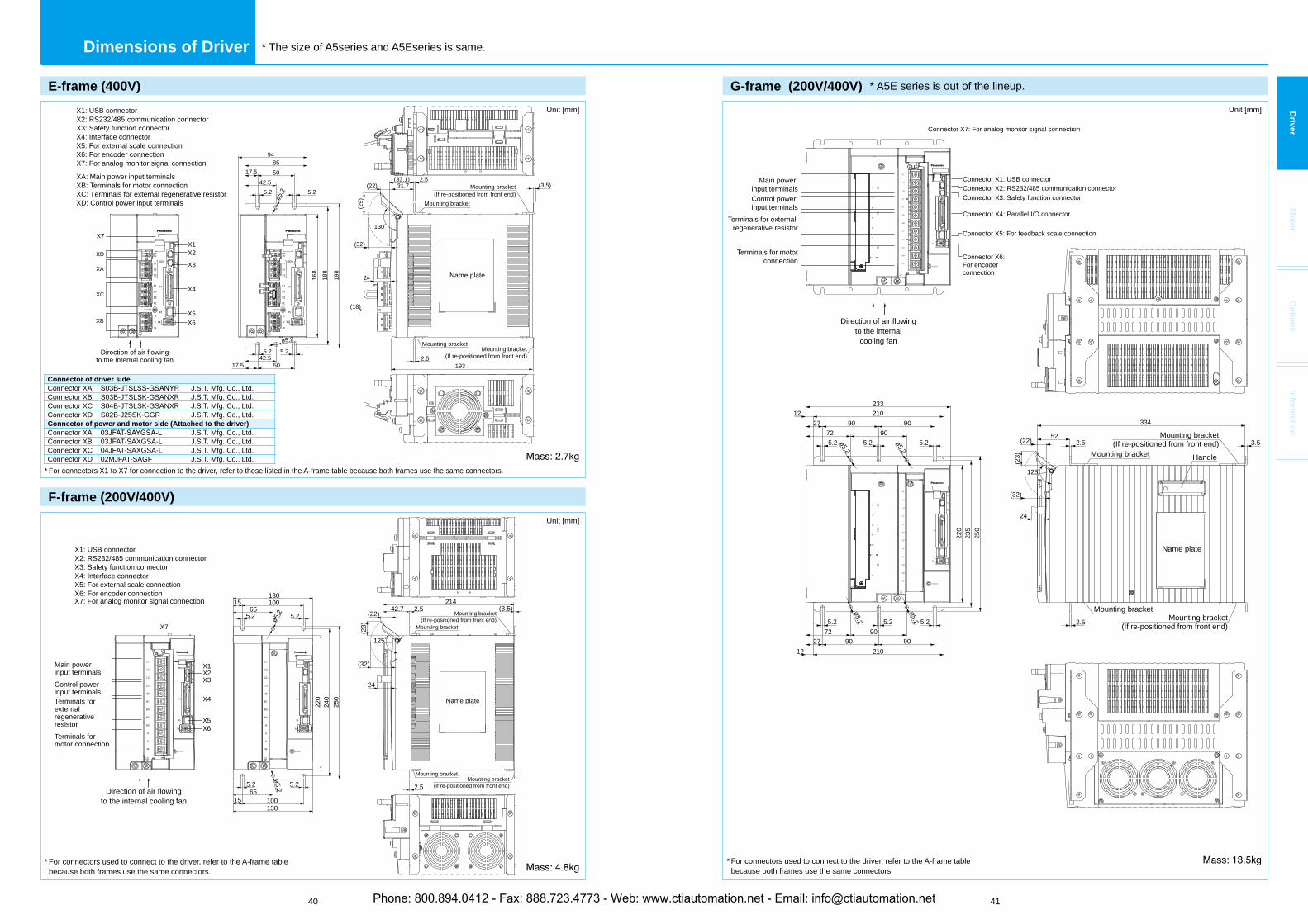
40 41
Driver
Mo
tor
Op
tion
sIn
form
ation
Dimensions of Driver * The size of A5series and A5Eseries is same.
E-frame (400V)
855017.5
42.55.2 5.2
94
198
188
168
ø5.2
ø5.2
5.25.242.5
5017.52.5
(3.5)
Mounting bracket Mounting bracket
(If re-positioned from front end)
Mounting bracket
Mounting bracket(If re-positioned from front end)
Name plate
(29)
(33.1)31.7(22)
(32)
24
130°
2.5
193
(18)
XD
XA
XC
XB
X1: USB connectorX2: RS232/485 communication connectorX3: Safety function connectorX4: Interface connectorX5: For external scale connectionX6: For encoder connectionX7: For analog monitor signal connection
XA: Main power input terminalsXB: Terminals for motor connectionXC: Terminals for external regenerative resistorXD: Control power input terminals
Direction of air flowingto the internal cooling fan
X1X2
X3
X4
X5X6
X7
Unit [mm]
Connector of driver sideConnector XA J.S.T. Mfg. Co., Ltd.Connector XB S03B-JTSLSK-GSANXR J.S.T. Mfg. Co., Ltd.Connector XC S04B-JTSLSK-GSANXR J.S.T. Mfg. Co., Ltd.Connector XD S02B-J25SK-GGR J.S.T. Mfg. Co., Ltd.Connector of power and motor side (Attached to the driver)Connector XA J.S.T. Mfg. Co., Ltd.Connector XB 03JFAT-SAXGSA-L J.S.T. Mfg. Co., Ltd.Connector XC 04JFAT-SAXGSA-L J.S.T. Mfg. Co., Ltd.Connector XD 02MJFAT-SAGF J.S.T. Mfg. Co., Ltd.
* For connectors X1 to X7 for connection to the driver, refer to those listed in the A-frame table because both frames use the same connectors.
F-frame (200V/400V)
X1: USB connectorX2: RS232/485 communication connectorX3: Safety function connectorX4: Interface connectorX5: For external scale connectionX6: For encoder connectionX7: For analog monitor signal connection
Main powerinput terminalsControl powerinput terminalsTerminals forexternalregenerativeresistorTerminals for motor connection
1001565
5.2 5.2
130
250
240
220
ø5.2 5.25.265
100130
15
Name plate
42.7214
2.5 (3.5)
Mounting bracketMounting bracket
(If re-positioned from front end)
Mounting bracket
Mounting bracket(If re-positioned from front end)
2.5
24
(23)
(22)
(32)
125°
Direction of air flowingto the internal cooling fan
X1X2X3
X4
X5X6
ø5.2
X7
Unit [mm]
* For connectors used to connect to the driver, refer to the A-frame table because both frames use the same connectors.
G-frame (200V/400V) * A5E series is out of the lineup.
NC
NC
NC
L2C
L1C
NC
NC
NC
DB3
DB2
DB1
DB4
L1
L2
L3
B1
B2
NC
U
V
W
X1
X2
X3
X4
X5
X6
CHARGE
NC
NC
NC
L2C
L1C
NC
NC
NC
DB3
DB2
DB1
DB4
X1
X2
X3
X4
X5
X6
CHARGE
L1
L2
L3
B1
B2
NC
U
V
W
Name plate
Handle
Direction of air flowingto the internal
cooling fan
Connector X1: USB connectorConnector X2: RS232/485 communication connectorConnector X3: Safety function connector
Connector X4: Parallel I/O connector
Connector X5: For feedback scale connection
Connector X6:For encoder connection
Main power input terminalsControl power input terminals
Terminals for external regenerative resistor
Terminals for motorconnection
Mounting bracketMounting bracket
(If re-positioned from front end)
Mounting bracket
Mounting bracket(If re-positioned from front end)
233
334
522.5
2.5
3.5
210
210
9090
90
909090
27
27
12
12
72
72
5.2 5.2 5.2
5.25.25.2
ø5.2
ø5.2
220
235
250
24
(23)
(22)
(32)
125°
ø5.2
ø5.2
Connector X7: For analog monitor signal connection
Unit [mm]
* For connectors used to connect to the driver, refer to the A-frame table because both frames use the same connectors.
Phone: 800.894.0412 - Fax: 888.723.4773 - Web: www.ctiautomation.net - Email: [email protected]
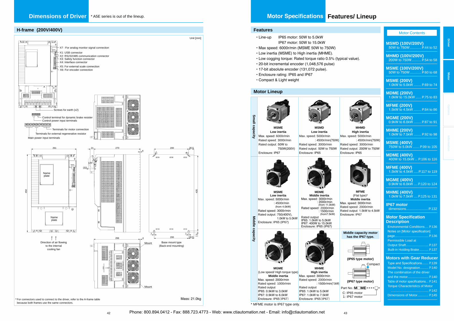
42 43
Driver
Mo
tor
Op
tion
sIn
form
ation
Dimensions of Driver
Mo
tor
Features/ Lineup* A5E series is out of the lineup.
Features
Motor Lineup
Sm
all capacity
MSMELow inertia
6000r/minRated speed: 3000r/minRated output: to
MSMDLow inertia
Max. speed 5000r/min4500r/min( )
Rated speed : 3000r/minRated output : to
MHMDHigh inertia
Max. speed 5000r/min4500r/min( )
Rated speed : 3000r/minRated output : to
Mid
dle cap
acity
MSMELow inertia
Max. speed4500r/min
Rated output
IP65 (IP67)
MDMEMiddle inertia
2000r/min
Rated output
MFME(Flat type)*
Middle inertia
Rated speed : 2000r/minRated output:
IP67
MGME(Low speed/ High torque type)
Middle inertia
Rated speed : 1000r/minRated output
IP65(IP67)
MHMEHigh inertia
Rated speed : 2000r/min
Rated output
IP65(IP67)
Middle capacity motorhas the IP67 type.
(IP65 type motor)
Part No.:M□ME****□*C: IP65 motor1: IP67 motor
Compact
(IP67 type motor)
* MFME motor is IP67 type only.
Motor Contents
MSMD (100V/200V)............ P.44 to 52
MHMD (100V/200V).......... P.54 to 58
MSME (100V/200V)............ P.60 to 68
MSME (200V)........ P.69 to 74
MDME (200V)...... P.75 to 83
MFME (200V)........ P.84 to 86
MGME (200V)........ P.87 to 91
MHME (200V)........ P.92 to 98
MSME (400V)....... P.99 to 105
MDME (400V)... P.106 to 116
MFME (400V).....P.117 to 119
MGME (400V).... P.120 to 124
MHME (400V).... P.125 to 131
IP67 motordimensions....................... P.132
DescriptionEnvironmental Conditions.... P.136
page..................................... P.136Permissible Load at Output Shaft......................... P.137
Built-in Holding Brake.......... P.137
Motors with Gear Reducer....... P.139
Model No. designation......... P.140The combination of the driver and the motor....................... P.140
... P.141Torque Characteristics of Motor .....................................................P.142Dimensions of Motor............ P.145
H-frame (200V/400V)
X1
X2
X3
X4
X5
X6
CHARGE
L1 L2 L3 B1 B2 NC
L1C L2C DB1 DB2
U V W
Mount
Mount
(32)
125°
450
2614
435
200 30.5
30.52007
7.57
270
Base mount type(Back-end mounting)
Direction of air flowingto the internal
cooling fan
21
ø7 ø7
266 4
Control power input terminals
Screws for earth (x2)
X6: For encoder connection
X4: Interface connectorX3: Safety function connectorX2: RS232/485 communication connectorX1: USB connector
X5: For external scale connection
Control terminal for dynamic brake resister
Main power input terminals
Terminals for motor connectionTerminals for external regenerative resistor
Nameplate
Nameplate
X7 : For analog monitor signal connection
Unit [mm]
* For connectors used to connect to the driver, refer to the A-frame table because both frames use the same connectors.
Phone: 800.894.0412 - Fax: 888.723.4773 - Web: www.ctiautomation.net - Email: [email protected]

Torque characteristics (at AC200V of power voltage <Dotted line represents the torque at 10% less supply voltage.>)
Dimensions
<Cautions> Reduce the moment of inertia ratio if high speed response operation is required. Dimensions are subject to change without notice. Contact us or a dealer for the latest information. Read the Instruction Manual carefully and understand all precautions and remarks before using the products.
* □*2 The product that the end of driver model
designation has “E” is “positioning type”.Detail of model designation, refer to P.11.
Dimensions
<Cautions> Reduce the moment of inertia ratio if high speed response operation is required. Dimensions are subject to change without notice. Contact us or a dealer for the latest information. Read the Instruction Manual carefully and understand all precautions and remarks before using the products.
44 45
* □*2 The product that the end of driver model
designation has “E” is “positioning type”.Detail of model designation, refer to P.11.
Driver
Mo
tor
Op
tion
sIn
form
ation
AC100V
Motor model *1 MSMD5AZG1□ MSMD5AZS1□
Applicable driver *2ModelNo.
A5 series MADHT1105
A5E series MADHT1105E –
Frame symbol A-framePower supply capacity (kVA) 0.5
50Rated torque (N m) 0.16Momentary Max. peak torque (N m) 0.48Rated current (A(rms)) 1.1Max. current (A(o-p)) 4.7
Regenerative brakefrequency (times/min) Note)1
No limit Note)2
DV0P4280 No limit Note)2
Rated rotational speed (r/min) 3000Max. rotational speed (r/min) 5000
Moment of inertiaof rotor (×10 kg m2)
0.0250.027
Recommended moment of inertia ratio of the load and the rotor Note)3
30 times or less
Note)520-bit
Incremental17-bit
AbsoluteResolution per single turn 1,048,576 131,072
• (For details, refer to P.137) This brake will be released when it is energized.(Do not use this for braking the motor in motion. )
Static friction torque (N m) 0.29 or more
Engaging time (ms) 35 or less
Releasing time (ms) Note)4 20 or less
Exciting current (DC) (A) 0.3
Releasing voltage (DC) (V) 1 or more
Exciting voltage (DC) (V) 24±1.2
• Permissible load (For details, refer to P.137)
Duringassembly
Radial load P-direction (N) 147
Thrust load A-direction (N) 88
Thrust load B-direction (N) 117.6
Duringoperation
Radial load P-direction (N) 68.6
Thrust load A, B-direction (N) 58.8
Torque characteristics (at AC100V of power voltage <Dotted line represents the torque at 10% less supply voltage.>)
Mass (kg)/ 0.32
100V MSMD 50W [Low inertia, Small capacity]
With
ou
t oil seal
torque[N m]
rotational speed [r/min]
50
10095
100 20 30 40
0.25
0 1000 2000 3000 4000 5000
0.5(0.4)
Peak run range
(3600)
rated torque[%]
* Derating curve
With
oil seal
torque[N m]
rated torque[%]
* Derating curve
rotational speed [r/min]
50
100
7060
100 20 30 40
with Brake
withoutBrake
0.25
0 1000 2000 3000 4000 5000
Peak run range
0.5(0.4)
(3600)
<Without Brake>
* For the dimensions with brake, refer to the right page.
(a) Encoder connector(b) Motor connector
<Key way, center tap shaft>
32
38
454- 3.4*1
(a)
(b)
230
200
3672 25
8h6
30h7
26.5
(7)(7)
143h9
M3 depth 6
36.
2
12.5
*1 Use hexagon socket head screw for installation.
<D-cut shaft>
2025 7.5
90°±1
°
7.5
AC200V
Motor model *1 MSMD5AZG1□ MSMD5AZS1□
Applicable driver *2ModelNo.
A5 series MADHT1505
A5E series MADHT1505E –
Frame symbol A-framePower supply capacity (kVA) 0.5
50Rated torque (N m) 0.16Momentary Max. peak torque (N m) 0.48Rated current (A(rms)) 1.1Max. current (A(o-p)) 4.7
Regenerative brakefrequency (times/min) Note)1
No limit Note)2
DV0P4281 No limit Note)2
Rated rotational speed (r/min) 3000Max. rotational speed (r/min) 5000
Moment of inertiaof rotor (×10 kg m2)
0.0250.027
Recommended moment of inertia ratio of the load and the rotor Note)3
30 times or less
Note)520-bit
Incremental17-bit
AbsoluteResolution per single turn 1,048,576 131,072
200V MSMD 50W [Low inertia, Small capacity]
• (For details, refer to P.137) This brake will be released when it is energized.(Do not use this for braking the motor in motion. )
Static friction torque (N m) 0.29 or more
Engaging time (ms) 35 or less
Releasing time (ms) Note)4 20 or less
Exciting current (DC) (A) 0.3
Releasing voltage (DC) (V) 1 or more
Exciting voltage (DC) (V) 24±1.2
• Permissible load (For details, refer to P.137)
Duringassembly
Radial load P-direction (N) 147
Thrust load A-direction (N) 88
Thrust load B-direction (N) 117.6
Duringoperation
Radial load P-direction (N) 68.6
Thrust load A, B-direction (N) 58.8
Mass (kg)/ 0.53
With
ou
t oil seal
torque[N m]
rotational speed [r/min]
50
10095
100 20 30 40
0.25
0 1000 2000 3000 4000 5000
0.5(0.4)
Peak run range
(3600)
rated torque[%]
* Derating curve
With
oil seal
torque[N m]
rated torque[%]
* Derating curve
rotational speed [r/min]
50
100
7060
100 20 30 40
with Brake
withoutBrake
0.25
0 1000 2000 3000 4000 5000
Peak run range
0.5(0.4)
(3600)
4- 3.4*1
<With Brake>
* For the dimensions without brake, refer to the left page.
(a) Encoder connector(b) Brake connector(c) Motor connector
(a)
(b)(c)
230
200
36102 25
8h6
30h7
26.5
(7)(7)
32
38
45
143h9
M3 depth 6
36.
2
12.5
<Key way, center tap shaft>
<D-cut shaft>
2025 7.5
90°±1
°
7.5
*1 Use hexagon socket head screw for installation.
Phone: 800.894.0412 - Fax: 888.723.4773 - Web: www.ctiautomation.net - Email: [email protected]

Dimensions
<Cautions> Reduce the moment of inertia ratio if high speed response operation is required. Dimensions are subject to change without notice. Contact us or a dealer for the latest information. Read the Instruction Manual carefully and understand all precautions and remarks before using the products.
* □*2 The product that the end of driver model
designation has “E” is “positioning type”.Detail of model designation, refer to P.11.
Dimensions
<Cautions> Reduce the moment of inertia ratio if high speed response operation is required. Dimensions are subject to change without notice. Contact us or a dealer for the latest information. Read the Instruction Manual carefully and understand all precautions and remarks before using the products.
46 47
* □*2 The product that the end of driver model
designation has “E” is “positioning type”.Detail of model designation, refer to P.11.
Driver
Mo
tor
Op
tion
sIn
form
ation
100V MSMD 100W [Low inertia, Small capacity]
AC100V
Motor model *1 MSMD011G1□ MSMD011S1□
Applicable driver *2ModelNo.
A5 series MADHT1107
A5E series MADHT1107E –
Frame symbol A-framePower supply capacity (kVA) 0.4
100Rated torque (N m) 0.32Momentary Max. peak torque (N m) 0.95Rated current (A(rms)) 1.7Max. current (A(o-p)) 7.2
Regenerative brakefrequency (times/min) Note)1
No limit Note)2
DV0P4280 No limit Note)2
Rated rotational speed (r/min) 3000Max. rotational speed (r/min) 5000
Moment of inertiaof rotor (×10 kg m2)
0.0510.054
Recommended moment of inertia ratio of the load and the rotor Note)3
30 times or less
Note)520-bit
Incremental17-bit
AbsoluteResolution per single turn 1,048,576 131,072
• (For details, refer to P.137) This brake will be released when it is energized.(Do not use this for braking the motor in motion. )
Static friction torque (N m) 0.29 or more
Engaging time (ms) 35 or less
Releasing time (ms) Note)4 20 or less
Exciting current (DC) (A) 0.3
Releasing voltage (DC) (V) 1 or more
Exciting voltage (DC) (V) 24±1.2
• Permissible load (For details, refer to P.137)
Duringassembly
Radial load P-direction (N) 147
Thrust load A-direction (N) 88
Thrust load B-direction (N) 117.6
Duringoperation
Radial load P-direction (N) 68.6
Thrust load A, B-direction (N) 58.8
Mass (kg)/ 0.47
Torque characteristics (at AC100V of power voltage <Dotted line represents the torque at 10% less supply voltage.>)
With
ou
t oil seal
torque[N m]
rotational speed [r/min]
50
10095
100 20 30 40
0.5
0 1000 2000 3000 4000 5000
1.0(0.8)(0.6) Peak run range
rated torque[%]
* Derating curve
With
oil seal
torque[N m]
rotational speed [r/min]
50
1007570
100 20 30 40
with Brake
withoutBrake
0.5
0 1000 2000 3000 4000 5000
1.0(0.8)(0.6)
rated torque[%]
* curve
<Without Brake>
* For the dimensions with brake, refer to the right page.
(a) Encoder connector(b) Motor connector(a)
(b)
230
200
3692 25
8h6
30h7
46.5
(7)(7)
32
38
45
143h9
M3 depth 6
36.
2
12.54- 3.4*1
<Key way, center tap shaft>
<D-cut shaft>
2025 7.5
90°±1
°
7.5
*1 Use hexagon socket head screw for installation.
200V MSMD 100W [Low inertia, Small capacity]
AC200V
Motor model *1 MSMD012G1□ MSMD012S1□
Applicable driver *2ModelNo.
A5 series MADHT1505
A5E series MADHT1505E –
Frame symbol A-framePower supply capacity (kVA) 0.5
100Rated torque (N m) 0.32Momentary Max. peak torque (N m) 0.95Rated current (A(rms)) 1.1Max. current (A(o-p)) 4.7
Regenerative brakefrequency (times/min) Note)1
No limit Note)2
DV0P4281 No limit Note)2
Rated rotational speed (r/min) 3000Max. rotational speed (r/min) 5000
Moment of inertiaof rotor (×10 kg m2)
0.0510.054
Recommended moment of inertia ratio of the load and the rotor Note)3
30 times or less
Note)520-bit
Incremental17-bit
AbsoluteResolution per single turn 1,048,576 131,072
• (For details, refer to P.137) This brake will be released when it is energized.(Do not use this for braking the motor in motion. )
Static friction torque (N m) 0.29 or more
Engaging time (ms) 35 or less
Releasing time (ms) Note)4 20 or less
Exciting current (DC) (A) 0.3
Releasing voltage (DC) (V) 1 or more
Exciting voltage (DC) (V) 24±1.2
• Permissible load (For details, refer to P.137)
Duringassembly
Radial load P-direction (N) 147
Thrust load A-direction (N) 88
Thrust load B-direction (N) 117.6
Duringoperation
Radial load P-direction (N) 68.6
Thrust load A, B-direction (N) 58.8
Mass (kg)/ 0.68
With
ou
t oil seal
torque[N m]
rotational speed [r/min]
50
10095
100 20 30 40
0.5
0 1000 2000 3000 4000 5000
1.0(0.95)
(0.32)
Peak run range
rated torque[%]
* Derating curve
With
oil seal
torque[N m]
rotational speed [r/min]
50
1007570
100 20 30 40
with Brake
withoutBrake
0.5
0 1000 2000 3000 4000 5000
1.0(0.95)
(0.32)
Peak run range
rated torque[%]
* Derating curve
(a) Encoder connector(b) Brake connector(c) Motor connector
(a)
(b)
(c)
230
200
36122 25
8h6
30h7
46.5
(7)(7)
<With Brake>
* For the dimensions without brake, refer to the left page.
32
38
454- 3.4*1 14
3h9
M3 depth 6
36.
2
12.5
<Key way, center tap shaft>
<D-cut shaft>
2025 7.5
90°±1
°
7.5
*1 Use hexagon socket head screw for installation.
Torque characteristics (at AC200V of power voltage)
Phone: 800.894.0412 - Fax: 888.723.4773 - Web: www.ctiautomation.net - Email: [email protected]

Torque characteristics (at AC200V of power voltage <Dotted line represents the torque at 10% less supply voltage.>)
Dimensions
<Cautions> Reduce the moment of inertia ratio if high speed response operation is required. Dimensions are subject to change without notice. Contact us or a dealer for the latest information. Read the Instruction Manual carefully and understand all precautions and remarks before using the products.
* □*2 The product that the end of driver model
designation has “E” is “positioning type”.Detail of model designation, refer to P.11.
Dimensions
<Cautions> Reduce the moment of inertia ratio if high speed response operation is required. Dimensions are subject to change without notice. Contact us or a dealer for the latest information. Read the Instruction Manual carefully and understand all precautions and remarks before using the products.
48 49
* □*2 The product that the end of driver model
designation has “E” is “positioning type”.Detail of model designation, refer to P.11.
Driver
Mo
tor
Op
tion
sIn
form
ation
100V MSMD 200W [Low inertia, Small capacity]
AC100V
Motor model *1 MSMD021G1□ MSMD021S1□
Applicable driver *2ModelNo.
A5 series MBDHT2110
A5E series MBDHT2110E –
Frame symbol B-framePower supply capacity (kVA) 0.5
200Rated torque (N m) 0.64Momentary Max. peak torque (N m) 1.91Rated current (A(rms)) 2.5Max. current (A(o-p)) 10.6
Regenerative brakefrequency (times/min) Note)1
No limit Note)2
DV0P4283 No limit Note)2
Rated rotational speed (r/min) 3000Max. rotational speed (r/min) 5000
Moment of inertiaof rotor (×10 kg m2)
0.140.16
Recommended moment of inertia ratio of the load and the rotor Note)3
30 times or less
Note)520-bit
Incremental17-bit
AbsoluteResolution per single turn 1,048,576 131,072
• (For details, refer to P.137) This brake will be released when it is energized.(Do not use this for braking the motor in motion. )
Static friction torque (N m) 1.27 or more
Engaging time (ms) 50 or less
Releasing time (ms) Note)4 15 or less
Exciting current (DC) (A) 0.36
Releasing voltage (DC) (V) 1 or more
Exciting voltage (DC) (V) 24±1.2
• Permissible load (For details, refer to P.137)
Duringassembly
Radial load P-direction (N) 392
Thrust load A-direction (N) 147
Thrust load B-direction (N) 196
Duringoperation
Radial load P-direction (N) 245
Thrust load A, B-direction (N) 98
Mass (kg)/ 0.82
Torque characteristics (at AC100V of power voltage <Dotted line represents the torque at 10% less supply voltage.>)
With
ou
t oil seal
torque[N m]
rotational speed [r/min]
50
100
100 20 30 40
1.0
0 1000 2000 3000 4000 5000
2.0
(0.5)(0.9)
Peak run range
(3600)
rated torque[%]
* Derating curve
With
oil seal
torque[N m]
rotational speed [r/min]
50
1008070
100 20 30 40
with Brake
withoutBrake
1.0
0 1000 2000 3000 4000 5000
2.0
(0.9)(0.5)
Peak run range
(3600)
rated torque[%]
* Derating curve
<Without Brake>
* For the dimensions with brake, refer to the right page.
(a) Encoder connector(b) Motor connector
43
60
ø70
4-ø4.5*1220
200
36.579.5 30
ø11h
6ø5
0h7
(7) (7)
(a)
(b)
<Key way, center tap shaft>
<D-cut shaft>
20 4h9
M4 depth 8
48.
5
18
22
30 10
90°±1
°
10
*1 Use hexagon socket head screw for installation.
200V MSMD 200W [Low inertia, Small capacity]
AC200V
Motor model *1 MSMD022G1□ MSMD022S1□
Applicable driver *2ModelNo.
A5 series MADHT1507
A5E series MADHT1507E –
Frame symbol A-framePower supply capacity (kVA) 0.5
200Rated torque (N m) 0.64Momentary Max. peak torque (N m) 1.91Rated current (A(rms)) 1.6Max. current (A(o-p)) 6.9
Regenerative brakefrequency (times/min) Note)1
No limit Note)2
DV0P4283 No limit Note)2
Rated rotational speed (r/min) 3000Max. rotational speed (r/min) 5000
Moment of inertiaof rotor (×10 kg m2)
0.140.16
Recommended moment of inertia ratio of the load and the rotor Note)3
30 times or less
Note)520-bit
Incremental17-bit
AbsoluteResolution per single turn 1,048,576 131,072
• (For details, refer to P.137) This brake will be released when it is energized.(Do not use this for braking the motor in motion. )
Static friction torque (N m) 1.27 or more
Engaging time (ms) 50 or less
Releasing time (ms) Note)4 15 or less
Exciting current (DC) (A) 0.36
Releasing voltage (DC) (V) 1 or more
Exciting voltage (DC) (V) 24±1.2
• Permissible load (For details, refer to P.137)
Duringassembly
Radial load P-direction (N) 392
Thrust load A-direction (N) 147
Thrust load B-direction (N) 196
Duringoperation
Radial load P-direction (N) 245
Thrust load A, B-direction (N) 98
Mass (kg)/ 1.3
With
ou
t oil seal
torque[N m]
rotational speed [r/min]
50
100
100 20 30 40
1.0
0 1000 2000 3000 4000 5000
2.0
(1.5)(1.2)
Peak run range
(4500)
rated torque[%]
* Derating curve
With
oil seal
torque[N m]
rotational speed [r/min]
50
1008070
100 20 30 40
with Brake
withoutBrake
1.0
0 1000 2000 3000 4000 5000
2.0
(1.5)(1.2)
Peak run range
(4500)
rated torque[%]
* Derating curve
(a) Encoder connector(b) Brake connector(c) Motor connector
<Key way, center tap shaft>
<D-cut shaft>
20 4h9
M4 depth 8
48.
5
18
22
30 10
90°±1
°
10
<With Brake>
* For the dimensions without brake, refer to the left page.
220
200
36.5116 30
ø11h
6ø5
0h7
(7) (7)
(a)(b)
(c)
43
60
ø70
4-ø4.5*1
*1 Use hexagon socket head screw for installation.
Phone: 800.894.0412 - Fax: 888.723.4773 - Web: www.ctiautomation.net - Email: [email protected]
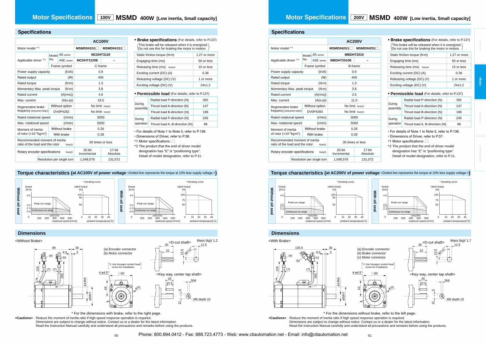
Torque characteristics (at AC200V of power voltage <Dotted line represents the torque at 10% less supply voltage.>)
Dimensions
<Cautions> Reduce the moment of inertia ratio if high speed response operation is required. Dimensions are subject to change without notice. Contact us or a dealer for the latest information. Read the Instruction Manual carefully and understand all precautions and remarks before using the products.
* □*2 The product that the end of driver model
designation has “E” is “positioning type”.Detail of model designation, refer to P.11.
Dimensions
<Cautions> Reduce the moment of inertia ratio if high speed response operation is required. Dimensions are subject to change without notice. Contact us or a dealer for the latest information. Read the Instruction Manual carefully and understand all precautions and remarks before using the products.
50 51
* □*2 The product that the end of driver model
designation has “E” is “positioning type”.Detail of model designation, refer to P.11.
Driver
Mo
tor
Op
tion
sIn
form
ation
100V MSMD 400W [Low inertia, Small capacity]
AC100V
Motor model *1 MSMD041G1□ MSMD041S1□
Applicable driver *2ModelNo.
A5 series MCDHT3120
A5E series MCDHT3120E –
Frame symbol C-framePower supply capacity (kVA) 0.9
400Rated torque (N m) 1.3Momentary Max. peak torque (N m) 3.8Rated current (A(rms)) 4.6Max. current (A(o-p)) 19.5
Regenerative brakefrequency (times/min) Note)1
No limit Note)2
DV0P4282 No limit Note)2
Rated rotational speed (r/min) 3000Max. rotational speed (r/min) 5000
Moment of inertiaof rotor (×10 kg m2)
0.260.28
Recommended moment of inertia ratio of the load and the rotor Note)3
30 times or less
Note)520-bit
Incremental17-bit
AbsoluteResolution per single turn 1,048,576 131,072
• (For details, refer to P.137) This brake will be released when it is energized.(Do not use this for braking the motor in motion. )
Static friction torque (N m) 1.27 or more
Engaging time (ms) 50 or less
Releasing time (ms) Note)4 15 or less
Exciting current (DC) (A) 0.36
Releasing voltage (DC) (V) 1 or more
Exciting voltage (DC) (V) 24±1.2
• Permissible load (For details, refer to P.137)
Duringassembly
Radial load P-direction (N) 392
Thrust load A-direction (N) 147
Thrust load B-direction (N) 196
Duringoperation
Radial load P-direction (N) 245
Thrust load A, B-direction (N) 98
Torque characteristics (at AC100V of power voltage <Dotted line represents the torque at 10% less supply voltage.>)
Mass (kg)/ 1.2
With
ou
t oil seal
torque[N m]
rotational speed [r/min]
50
90100
100 20 30 40
2.0
0 1000 2000 3000 4000 5000
4.0
(1.3)(0.6)
Peak run range
(3200)(2800)
rated torque[%]
* Derating curve
With
oil seal
torque[N m]
rotational speed [r/min]
50
100
75
100 20 30 40
2.0
0 1000 2000 3000 4000 5000
4.0
(1.3)(0.6)
Peak run range
(3200)(2800)
rated torque[%]
* Derating curve
<Without Brake>
* For the dimensions with brake, refer to the right page.
(a) (b)
220
200
36.599 30
ø14h
6ø5
0h7
(7) (7)
(a) Encoder connector(b) Motor connector
25 5h9
M5 depth 10
511
22.5
43
60
ø70
4-ø4.5*1
22
30 12.5
90°±1
°
12.5
<Key way, center tap shaft>
<D-cut shaft>
*1 Use hexagon socket head screw for installation.
200V MSMD 400W [Low inertia, Small capacity]
AC200V
Motor model *1 MSMD042G1□ MSMD042S1□
Applicable driver *2ModelNo.
A5 series MBDHT2510
A5E series MBDHT2510E –
Frame symbol B-framePower supply capacity (kVA) 0.9
400Rated torque (N m) 1.3Momentary Max. peak torque (N m) 3.8Rated current (A(rms)) 2.6Max. current (A(o-p)) 11.0
Regenerative brakefrequency (times/min) Note)1
No limit Note)2
DV0P4283 No limit Note)2
Rated rotational speed (r/min) 3000Max. rotational speed (r/min) 5000
Moment of inertiaof rotor (×10 kg m2)
0.260.28
Recommended moment of inertia ratio of the load and the rotor Note)3
30 times or less
Note)520-bit
Incremental17-bit
AbsoluteResolution per single turn 1,048,576 131,072
• (For details, refer to P.137) This brake will be released when it is energized.(Do not use this for braking the motor in motion. )
Static friction torque (N m) 1.27 or more
Engaging time (ms) 50 or less
Releasing time (ms) Note)4 15 or less
Exciting current (DC) (A) 0.36
Releasing voltage (DC) (V) 1 or more
Exciting voltage (DC) (V) 24±1.2
• Permissible load (For details, refer to P.137)
Duringassembly
Radial load P-direction (N) 392
Thrust load A-direction (N) 147
Thrust load B-direction (N) 196
Duringoperation
Radial load P-direction (N) 245
Thrust load A, B-direction (N) 98
Mass (kg)/ 1.7
With
ou
t oil seal
torque[N m]
rotational speed [r/min]
50
90100
100 20 30 40
2.0
0 1000 2000 3000 4000 5000
4.0
(1.3)(1.7)
Peak run range
(3800)(3400)
rated torque[%]
* Derating curve
With
oil seal
torque[N m]
rotational speed [r/min]
50
100
75
100 20 30 40
2.0
0 1000 2000 3000 4000 5000
4.0
(1.3)(1.7)
Peak run range
(3800)(3400)
rated torque[%]
* Derating curve
(a) Encoder connector(b) Brake connector(c) Motor connector(a)
(b)(c)
<With Brake>
* For the dimensions without brake, refer to the left page.
220
200
36.5135.5 30
ø14h
6ø5
0h7
(7) (7)
43
60
ø70
4-ø4.5*1
25 5h9
M5 depth 10
511
22.5
22
30 12.5
90°±1
°
12.5
<Key way, center tap shaft>
<D-cut shaft>
*1 Use hexagon socket head screw for installation.
Phone: 800.894.0412 - Fax: 888.723.4773 - Web: www.ctiautomation.net - Email: [email protected]
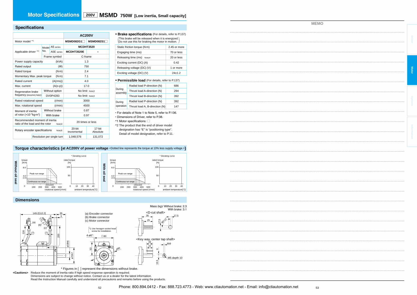
53
MEMO
Driver
Mo
tor
Op
tion
sIn
form
ation
Torque characteristics (at AC200V of power voltage <Dotted line represents the torque at 10% less supply voltage.>)
Dimensions
<Cautions> Reduce the moment of inertia ratio if high speed response operation is required. Dimensions are subject to change without notice. Contact us or a dealer for the latest information. Read the Instruction Manual carefully and understand all precautions and remarks before using the products.
52
* □*2 The product that the end of driver model
designation has “E” is “positioning type”.Detail of model designation, refer to P.11.
200V MSMD 750W [Low inertia, Small capacity]
AC200V
Motor model *1 MSMD082G1□ MSMD082S1□
Applicable driver *2ModelNo.
A5 series MCDHT3520
A5E series MCDHT3520E –
Frame symbol C-framePower supply capacity (kVA) 1.3
750Rated torque (N m) 2.4Momentary Max. peak torque (N m) 7.1Rated current (A(rms)) 4.0Max. current (A(o-p)) 17.0
Regenerative brakefrequency (times/min) Note)1
No limit Note)2
DV0P4283 No limit Note)2
Rated rotational speed (r/min) 3000Max. rotational speed (r/min) 4500
Moment of inertiaof rotor (×10 kg m2)
0.870.97
Recommended moment of inertia ratio of the load and the rotor Note)3
20 times or less
Note)520-bit
Incremental17-bit
AbsoluteResolution per single turn 1,048,576 131,072
• (For details, refer to P.137) This brake will be released when it is energized.(Do not use this for braking the motor in motion. )
Static friction torque (N m) 2.45 or more
Engaging time (ms) 70 or less
Releasing time (ms) Note)4 20 or less
Exciting current (DC) (A) 0.42
Releasing voltage (DC) (V) 1 or more
Exciting voltage (DC) (V) 24±1.2
• Permissible load (For details, refer to P.137)
Duringassembly
Radial load P-direction (N) 686
Thrust load A-direction (N) 294
Thrust load B-direction (N) 392
Duringoperation
Radial load P-direction (N) 392
Thrust load A, B-direction (N) 147
With
ou
t oil seal
torque[N m]
rotational speed [r/min]
50
100
100 20 30 40
4.0
0 1000 2000 3000 4000 5000
8.0
(3.0)
Peak run range
(3600)(3200)
rated torque[%]
* Derating curve
With
oil seal
torque[N m]
rotational speed [r/min]
50
100
100 20 30 40
4.0
0 1000 2000 3000 4000 5000
8.0
(3.0)
Peak run range
(3600)(3200)
rated torque[%]
* Derating curve
(a) Encoder connector(b) Brake connector(c) Motor connector
220
200
38149.2[112.2]
* Figures in [ ] represent the dimensions without brake.
35
ø19h
6
ø70h
7
(7) (7)
53
80
ø90
(a)(b)
(c)
<Key way, center tap shaft>
<D-cut shaft>
25
25
35 17.5
90°±1
°
17.5
6h9
M5 depth 10
615
.5
22
4-ø6*1
*1 Use hexagon socket head screw for installation.
Phone: 800.894.0412 - Fax: 888.723.4773 - Web: www.ctiautomation.net - Email: [email protected]

Torque characteristics (at AC200V of power voltage <Dotted line represents the torque at 10% less supply voltage.>)
Dimensions
<Cautions> Reduce the moment of inertia ratio if high speed response operation is required. Dimensions are subject to change without notice. Contact us or a dealer for the latest information. Read the Instruction Manual carefully and understand all precautions and remarks before using the products.
* □*2 The product that the end of driver model
designation has “E” is “positioning type”.Detail of model designation, refer to P.11.
Dimensions
<Cautions> Reduce the moment of inertia ratio if high speed response operation is required. Dimensions are subject to change without notice. Contact us or a dealer for the latest information. Read the Instruction Manual carefully and understand all precautions and remarks before using the products.
54 55
* □*2 The product that the end of driver model
designation has “E” is “positioning type”.Detail of model designation, refer to P.11.
Driver
Mo
tor
Op
tion
sIn
form
ation
200V MHMD 200W [High inertia, Small capacity]
AC200V
Motor model *1 MHMD022G1□ MHMD022S1□
Applicable driver *2ModelNo.
A5 series MADHT1507
A5E series MADHT1507E –
Frame symbol A-framePower supply capacity (kVA) 0.5
200Rated torque (N m) 0.64Momentary Max. peak torque (N m) 1.91Rated current (A(rms)) 1.6Max. current (A(o-p)) 6.9
Regenerative brakefrequency (times/min) Note)1
No limit Note)2
DV0P4283 No limit Note)2
Rated rotational speed (r/min) 3000Max. rotational speed (r/min) 5000
Moment of inertiaof rotor (×10 kg m2)
0.420.45
Recommended moment of inertia ratio of the load and the rotor Note)3
30 times or less
Note)520-bit
Incremental17-bit
AbsoluteResolution per single turn 1,048,576 131,072
• (For details, refer to P.137) This brake will be released when it is energized.(Do not use this for braking the motor in motion. )
Static friction torque (N m) 1.27 or more
Engaging time (ms) 50 or less
Releasing time (ms) Note)4 15 or less
Exciting current (DC) (A) 0.36
Releasing voltage (DC) (V) 1 or more
Exciting voltage (DC) (V) 24±1.2
• Permissible load (For details, refer to P.137)
Duringassembly
Radial load P-direction (N) 392
Thrust load A-direction (N) 147
Thrust load B-direction (N) 196
Duringoperation
Radial load P-direction (N) 245
Thrust load A, B-direction (N) 98
Mass (kg)/ 1.4
(a) Encoder connector(b) Brake connector(c) Motor connector
204h9
M4 depth 8
48.
5
18
*1 Use hexagon socket head screw for installation.
<With Brake>
* For the dimensions without brake, refer to the left page.
<Key way, center tap shaft>
<D-cut shaft>
2230 10
90°±1
°
10
220
200
135.56.5 3
30
11h6
50h7
43
□60
70
(7) (7)
4- 4.5*1
(a)(b)
(c)
With
ou
t oil seal
50
100
100 20 30 40
2.0
(1.5)(1.2)
(4500)
1.0
0 1000 2000 3000 4000 5000
torque[N m]
rotational speed [r/min]
Peak run range
rated torque[%]
* Derating curve
With
oil seal
5070
10080
100 20 30 40
2.0
(1.5)(1.2)
(4500)
1.0
0 1000 2000 3000 4000 5000
torque[N m]
rotational speed [r/min]
Peak run range with Brake
withoutBrake
rated torque[%]
* Derating curve
100V MHMD 200W [High inertia, Small capacity]
AC100V
Motor model *1 MHMD021G1□ MHMD021S1□
Applicable driver *2ModelNo.
A5 series MBDHT2110
A5E series MBDHT2110E –
Frame symbol B-framePower supply capacity (kVA) 0.5
200Rated torque (N m) 0.64Momentary Max. peak torque (N m) 1.91Rated current (A(rms)) 2.5Max. current (A(o-p)) 10.6
Regenerative brakefrequency (times/min) Note)1
No limit Note)2
DV0P4283 No limit Note)2
Rated rotational speed (r/min) 3000Max. rotational speed (r/min) 5000
Moment of inertiaof rotor (×10 kg m2)
0.420.45
Recommended moment of inertia ratio of the load and the rotor Note)3
30 times or less
Note)520-bit
Incremental17-bit
AbsoluteResolution per single turn 1,048,576 131,072
• (For details, refer to P.137) This brake will be released when it is energized.(Do not use this for braking the motor in motion. )
Static friction torque (N m) 1.27 or more
Engaging time (ms) 50 or less
Releasing time (ms) Note)4 15 or less
Exciting current (DC) (A) 0.36
Releasing voltage (DC) (V) 1 or more
Exciting voltage (DC) (V) 24±1.2
• Permissible load (For details, refer to P.137)
Duringassembly
Radial load P-direction (N) 392
Thrust load A-direction (N) 147
Thrust load B-direction (N) 196
Duringoperation
Radial load P-direction (N) 245
Thrust load A, B-direction (N) 98
Torque characteristics (at AC100V of power voltage <Dotted line represents the torque at 10% less supply voltage.>)
Mass (kg)/ 0.96
(a) Encoder connector(b) Motor connector
204h9
M4 depth 8
48.
5
18
*1 Use hexagon socket head screw for installation.
<Without Brake>
* For the dimensions with brake, refer to the right page.
<Key way, center tap shaft>
<D-cut shaft>
2230 10
90°±1
°
10
43
220
200
996.5 3
30
11h6
50h7
□60
(a) (b)
70
(7) (7)
4- 4.5*1
With
ou
t oil seal
50
100
100 20 30 40
2.0
(0.9)(0.5)
(3600)
1.0
0 1000 2000 3000 4000 5000
torque[N m]
rotational speed [r/min]
Peak run range
rated torque[%]
* Derating curve
With
oil seal
5070
10080
100 20 30 40
2.0
(0.9)(0.5)
(3600)
1.0
0 1000 2000 3000 4000 5000
torque[N m]
rotational speed [r/min]
Peak run range with Brake
withoutBrake
rated torque[%]
* Derating curve
Phone: 800.894.0412 - Fax: 888.723.4773 - Web: www.ctiautomation.net - Email: [email protected]

Torque characteristics (at AC200V of power voltage <Dotted line represents the torque at 10% less supply voltage.>)
Dimensions
<Cautions> Reduce the moment of inertia ratio if high speed response operation is required. Dimensions are subject to change without notice. Contact us or a dealer for the latest information. Read the Instruction Manual carefully and understand all precautions and remarks before using the products.
* □*2 The product that the end of driver model
designation has “E” is “positioning type”.Detail of model designation, refer to P.11.
Dimensions
<Cautions> Reduce the moment of inertia ratio if high speed response operation is required. Dimensions are subject to change without notice. Contact us or a dealer for the latest information. Read the Instruction Manual carefully and understand all precautions and remarks before using the products.
56 57
* □*2 The product that the end of driver model
designation has “E” is “positioning type”.Detail of model designation, refer to P.11.
Driver
Mo
tor
Op
tion
sIn
form
ation
100V MHMD 400W [High inertia, Small capacity]
AC100V
Motor model *1 MHMD041G1□ MHMD041S1□
Applicable driver *2ModelNo.
A5 series MCDHT3120
A5E series MCDHT3120E –
Frame symbol C-framePower supply capacity (kVA) 0.9
400Rated torque (N m) 1.3Momentary Max. peak torque (N m) 3.8Rated current (A(rms)) 4.6Max. current (A(o-p)) 19.5
Regenerative brakefrequency (times/min) Note)1
No limit Note)2
DV0P4282 No limit Note)2
Rated rotational speed (r/min) 3000Max. rotational speed (r/min) 5000
Moment of inertiaof rotor (×10 kg m2)
0.670.70
Recommended moment of inertia ratio of the load and the rotor Note)3
30 times or less
Note)520-bit
Incremental17-bit
AbsoluteResolution per single turn 1,048,576 131,072
Torque characteristics (at AC100V of power voltage <Dotted line represents the torque at 10% less supply voltage.>)
Mass (kg)/ 1.4
• (For details, refer to P.137) This brake will be released when it is energized.(Do not use this for braking the motor in motion. )
Static friction torque (N m) 1.27 or more
Engaging time (ms) 50 or less
Releasing time (ms) Note)4 15 or less
Exciting current (DC) (A) 0.36
Releasing voltage (DC) (V) 1 or more
Exciting voltage (DC) (V) 24±1.2
• Permissible load (For details, refer to P.137)
Duringassembly
Radial load P-direction (N) 392
Thrust load A-direction (N) 147
Thrust load B-direction (N) 196
Duringoperation
Radial load P-direction (N) 245
Thrust load A, B-direction (N) 98
(a) Encoder connector(b) Motor connector
255h9
M5 depth 10
511
22.5
<Without Brake>
* For the dimensions with brake, refer to the right page.
<Key way, center tap shaft>
<D-cut shaft>
2230 12.5
90°±1
°
12.5
*1 Use hexagon socket head screw for installation.
220
200
118.56.5 3
30
14h6
50h7
43
□60
70
(7) (7)
4- 4.5*1
(a) (b)
With
ou
t oil seal
50
10090
100 20 30 40
4.0
(0.6)(1.3)
(2800) (3200)
2.0
0 1000 2000 3000 4000 5000
torque[N m]
rotational speed [r/min]
Peak run range
rated torque[%]
* Derating curve
With
oil seal
50
75
100
100 20 30 40
4.0
(0.6)(1.3)
(2800) (3200)
2.0
0 1000 2000 3000 4000 5000
torque[N m]
rotational speed [r/min]
Peak run range
rated torque[%]
* Derating curve
200V MHMD 400W [High inertia, Small capacity]
AC200V
Motor model *1 MHMD042G1□ MHMD042S1□
Applicable driver *2ModelNo.
A5 series MBDHT2510
A5E series MBDHT2510E –
Frame symbol B-framePower supply capacity (kVA) 0.9
400Rated torque (N m) 1.3Momentary Max. peak torque (N m) 3.8Rated current (A(rms)) 2.6Max. current (A(o-p)) 11.0
Regenerative brakefrequency (times/min) Note)1
No limit Note)2
DV0P4283 No limit Note)2
Rated rotational speed (r/min) 3000Max. rotational speed (r/min) 5000
Moment of inertiaof rotor (×10 kg m2)
0.670.70
Recommended moment of inertia ratio of the load and the rotor Note)3
30 times or less
Note)520-bit
Incremental17-bit
AbsoluteResolution per single turn 1,048,576 131,072
• (For details, refer to P.137) This brake will be released when it is energized.(Do not use this for braking the motor in motion. )
Static friction torque (N m) 1.27 or more
Engaging time (ms) 50 or less
Releasing time (ms) Note)4 15 or less
Exciting current (DC) (A) 0.36
Releasing voltage (DC) (V) 1 or more
Exciting voltage (DC) (V) 24±1.2
• Permissible load (For details, refer to P.137)
Duringassembly
Radial load P-direction (N) 392
Thrust load A-direction (N) 147
Thrust load B-direction (N) 196
Duringoperation
Radial load P-direction (N) 245
Thrust load A, B-direction (N) 98
Mass (kg)/ 1.8
(a) Encoder connector(b) Brake connector(c) Motor connector
255h9
M5 depth 10
511
22.5
*1 Use hexagon socket head screw for installation.
<With Brake>
* For the dimensions without brake, refer to the left page.
<Key way, center tap shaft>
<D-cut shaft>
2230 12.5
90°±1
°
12.5
220
200
1556.5 3
30
14h6
50h7
43
□60
70
(7) (7)
4- 4.5*1
(a)(b)
(c)
With
ou
t oil seal
50
10090
100 20 30 40
4.0
(1.7)(1.3)
(3400) (3800)
2.0
0 1000 2000 3000 4000 5000
torque[N m]
rotational speed [r/min]
Peak run range
rated torque[%]
* Derating curve
With
oil seal
50
75
100
100 20 30 40
4.0
(1.7)(1.3)
(3400) (3800)
2.0
0 1000 2000 3000 4000 5000
torque[N m]
rotational speed [r/min]
Peak run range
rated torque[%]
* Derating curve
Phone: 800.894.0412 - Fax: 888.723.4773 - Web: www.ctiautomation.net - Email: [email protected]

59
MEMO
Driver
Mo
tor
Op
tion
sIn
form
ation
Torque characteristics (at AC200V of power voltage <Dotted line represents the torque at 10% less supply voltage.>)
Dimensions
<Cautions> Reduce the moment of inertia ratio if high speed response operation is required. Dimensions are subject to change without notice. Contact us or a dealer for the latest information. Read the Instruction Manual carefully and understand all precautions and remarks before using the products.
58
* □*2 The product that the end of driver model
designation has “E” is “positioning type”.Detail of model designation, refer to P.11.
200V MHMD 750W [High inertia, Small capacity]
• (For details, refer to P.137) This brake will be released when it is energized.(Do not use this for braking the motor in motion. )
Static friction torque (N m) 2.45 or more
Engaging time (ms) 70 or less
Releasing time (ms) Note)4 20 or less
Exciting current (DC) (A) 0.42
Releasing voltage (DC) (V) 1 or more
Exciting voltage (DC) (V) 24±1.2
• Permissible load (For details, refer to P.137)
Duringassembly
Radial load P-direction (N) 686
Thrust load A-direction (N) 294
Thrust load B-direction (N) 392
Duringoperation
Radial load P-direction (N) 392
Thrust load A, B-direction (N) 147
AC200V
Motor model *1 MHMD082G1□ MHMD082S1□
Applicable driver *2ModelNo.
A5 series MCDHT3520
A5E series MCDHT3520E –
Frame symbol C-framePower supply capacity (kVA) 1.3
750Rated torque (N m) 2.4Momentary Max. peak torque (N m) 7.1Rated current (A(rms)) 4.0Max. current (A(o-p)) 17.0
Regenerative brakefrequency (times/min) Note)1
No limit Note)2
DV0P4283 No limit Note)2
Rated rotational speed (r/min) 3000Max. rotational speed (r/min) 4500
Moment of inertiaof rotor (×10 kg m2)
1.511.61
Recommended moment of inertia ratio of the load and the rotor Note)3
20 times or less
Note)520-bit
Incremental17-bit
AbsoluteResolution per single turn 1,048,576 131,072
(a) Encoder connector(b) Brake connector(c) Motor connector
4- 6*1
*1 Use hexagon socket head screw for installation.
(a)(b)
(c)
220
200
164.2[127.2]8 3
35
19h6
53
70h7
90
□80
* Figures in [ ] represent the dimensions without brake.
<Key way, center tap shaft>
<D-cut shaft>
25
25
35 17.5
90°±1
°
17.5
6h9
M5 depth 10
615
.5
22
(7) (7)
With
ou
t oil seal
50
100
100 20 30 40
torque[N m]
rotational speed [r/min]
8.0
(3.0)
(3200) (3600)
4.0
0 1000 2000 3000 4000 5000
Peak run range
rated torque[%]
* Derating curve
With
oil seal
50
100
100 20 30 40
torque[N m]
rotational speed [r/min]
8.0
(3.0)
(3200) (3600)
4.0
0 1000 2000 3000 4000 5000
Peak run range
rated torque[%]
* Derating curve
Phone: 800.894.0412 - Fax: 888.723.4773 - Web: www.ctiautomation.net - Email: [email protected]
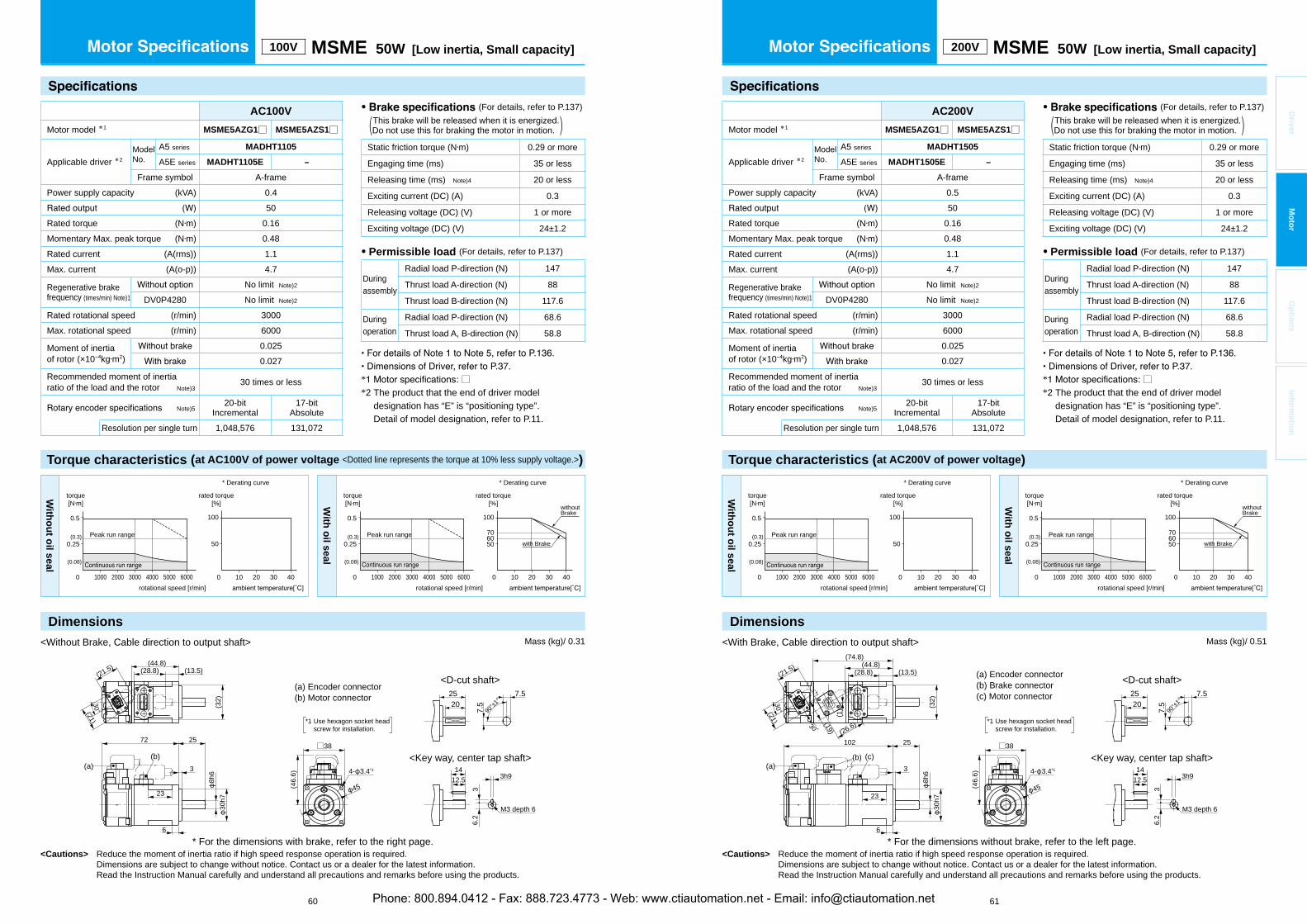
<Cautions> Reduce the moment of inertia ratio if high speed response operation is required. Dimensions are subject to change without notice. Contact us or a dealer for the latest information. Read the Instruction Manual carefully and understand all precautions and remarks before using the products.
* □*2 The product that the end of driver model
designation has “E” is “positioning type”.Detail of model designation, refer to P.11.
<Cautions> Reduce the moment of inertia ratio if high speed response operation is required. Dimensions are subject to change without notice. Contact us or a dealer for the latest information. Read the Instruction Manual carefully and understand all precautions and remarks before using the products.
60 61
* □*2 The product that the end of driver model
designation has “E” is “positioning type”.Detail of model designation, refer to P.11.
Driver
Mo
tor
Op
tion
sIn
form
ation
* For the dimensions without brake, refer to the left page.
143h9
M3 depth 6
36.
2
12.5
<With Brake, Cable direction to output shaft>
(a) Encoder connector(b) Brake connector(c) Motor connector
2025 7.5
90°±1
°
7.5
<Key way, center tap shaft>
<D-cut shaft>
*1 Use hexagon socket head screw for installation.
□3825
3
8h6
30h723
102
(21.5)
30°
30°
(46.
6)
(32)
(74.8)(44.8)
(13.5)(28.8)
(a)(b) (c)
45
6
(19)
(21)
(1)
(26.6)
4- 3.4*1
<Without Brake, Cable direction to output shaft>
* For the dimensions with brake, refer to the right page.
143h9
36.
2
12.5
(a) Encoder connector(b) Motor connector
M3 depth 6
2025 7.5
90°±1
°
7.5
<Key way, center tap shaft>
<D-cut shaft>
*1 Use hexagon socket head screw for installation.
25
3
8h6
30h7
23
6
72□38
45
4- 3.4*1
(21.5)
30°
(46.
6)
(32)
(44.8)(13.5)(28.8)
(a)(b)
(21)
AC100V
Motor model *1 MSME5AZG1□ MSME5AZS1□
Applicable driver *2ModelNo.
A5 series MADHT1105
A5E series MADHT1105E –
Frame symbol A-framePower supply capacity (kVA) 0.4
50Rated torque (N m) 0.16Momentary Max. peak torque (N m) 0.48Rated current (A(rms)) 1.1Max. current (A(o-p)) 4.7
Regenerative brakefrequency (times/min) Note)1
No limit Note)2
DV0P4280 No limit Note)2
Rated rotational speed (r/min) 3000Max. rotational speed (r/min) 6000
Moment of inertiaof rotor (×10 kg m2)
0.0250.027
Recommended moment of inertia ratio of the load and the rotor Note)3
30 times or less
Note)520-bit
Incremental17-bit
AbsoluteResolution per single turn 1,048,576 131,072
100V MSME 50W [Low inertia, Small capacity] 200V MSME 50W [Low inertia, Small capacity]
• (For details, refer to P.137) This brake will be released when it is energized.(Do not use this for braking the motor in motion. )
Static friction torque (N m) 0.29 or more
Engaging time (ms) 35 or less
Releasing time (ms) Note)4 20 or less
Exciting current (DC) (A) 0.3
Releasing voltage (DC) (V) 1 or more
Exciting voltage (DC) (V) 24±1.2
• Permissible load (For details, refer to P.137)
Duringassembly
Radial load P-direction (N) 147
Thrust load A-direction (N) 88
Thrust load B-direction (N) 117.6
Duringoperation
Radial load P-direction (N) 68.6
Thrust load A, B-direction (N) 58.8
Torque characteristics (at AC100V of power voltage <Dotted line represents the torque at 10% less supply voltage.>)
Mass (kg)/ 0.31
AC200V
Motor model *1 MSME5AZG1□ MSME5AZS1□
Applicable driver *2ModelNo.
A5 series MADHT1505
A5E series MADHT1505E –
Frame symbol A-framePower supply capacity (kVA) 0.5
50Rated torque (N m) 0.16Momentary Max. peak torque (N m) 0.48Rated current (A(rms)) 1.1Max. current (A(o-p)) 4.7
Regenerative brakefrequency (times/min) Note)1
No limit Note)2
DV0P4280 No limit Note)2
Rated rotational speed (r/min) 3000Max. rotational speed (r/min) 6000
Moment of inertiaof rotor (×10 kg m2)
0.0250.027
Recommended moment of inertia ratio of the load and the rotor Note)3
30 times or less
Note)520-bit
Incremental17-bit
AbsoluteResolution per single turn 1,048,576 131,072
• (For details, refer to P.137) This brake will be released when it is energized.(Do not use this for braking the motor in motion. )
Static friction torque (N m) 0.29 or more
Engaging time (ms) 35 or less
Releasing time (ms) Note)4 20 or less
Exciting current (DC) (A) 0.3
Releasing voltage (DC) (V) 1 or more
Exciting voltage (DC) (V) 24±1.2
• Permissible load (For details, refer to P.137)
Duringassembly
Radial load P-direction (N) 147
Thrust load A-direction (N) 88
Thrust load B-direction (N) 117.6
Duringoperation
Radial load P-direction (N) 68.6
Thrust load A, B-direction (N) 58.8
Mass (kg)/ 0.51
With
ou
t oil seal
50
100
100 20 30 40
0.5
(0.3)
(0.08)
0.25
0 1000 2000 3000 4000 5000 6000
torque[N m]
rotational speed [r/min]
Peak run range
rated torque[%]
* Derating curve
With
oil seal
5060
100
70
100 20 30 40
0.5
(0.3)
(0.08)
0.25
0 1000 2000 3000 4000 5000 6000
torque[N m]
rotational speed [r/min]
Peak run rangewith Brake
withoutBrake
rated torque[%]
* Derating curve
With
ou
t oil seal
50
100
100 20 30 40
0.5
(0.3)
(0.08)
0.25
0 1000 2000 3000 4000 5000 6000
torque[N m]
rotational speed [r/min]
Peak run range
rated torque[%]
* Derating curve
With
oil seal
5060
100
70
100 20 30 40
0.5
(0.3)
(0.08)
0.25
0 1000 2000 3000 4000 5000 6000
torque[N m]
rotational speed [r/min]
Peak run rangewith Brake
withoutBrake
rated torque[%]
* Derating curve
Torque characteristics (at AC200V of power voltage)
Dimensions Dimensions
Phone: 800.894.0412 - Fax: 888.723.4773 - Web: www.ctiautomation.net - Email: [email protected]

<Cautions> Reduce the moment of inertia ratio if high speed response operation is required. Dimensions are subject to change without notice. Contact us or a dealer for the latest information. Read the Instruction Manual carefully and understand all precautions and remarks before using the products.
* □*2 The product that the end of driver model
designation has “E” is “positioning type”.Detail of model designation, refer to P.11.
<Cautions> Reduce the moment of inertia ratio if high speed response operation is required. Dimensions are subject to change without notice. Contact us or a dealer for the latest information. Read the Instruction Manual carefully and understand all precautions and remarks before using the products.
62 63
* □*2 The product that the end of driver model
designation has “E” is “positioning type”.Detail of model designation, refer to P.11.
Driver
Mo
tor
Op
tion
sIn
form
ation
• (For details, refer to P.137) This brake will be released when it is energized.(Do not use this for braking the motor in motion. )
Static friction torque (N m) 0.29 or more
Engaging time (ms) 35 or less
Releasing time (ms) Note)4 20 or less
Exciting current (DC) (A) 0.3
Releasing voltage (DC) (V) 1 or more
Exciting voltage (DC) (V) 24±1.2
• Permissible load (For details, refer to P.137)
Duringassembly
Radial load P-direction (N) 147
Thrust load A-direction (N) 88
Thrust load B-direction (N) 117.6
Duringoperation
Radial load P-direction (N) 68.6
Thrust load A, B-direction (N) 58.8
100V MSME 100W [Low inertia, Small capacity] 200V MSME 100W [Low inertia, Small capacity]
AC100V
Motor model *1 MSME011G1□ MSME011S1□
Applicable driver *2ModelNo.
A5 series MADHT1107
A5E series MADHT1107E –
Frame symbol A-framePower supply capacity (kVA) 0.4
100Rated torque (N m) 0.32Momentary Max. peak torque (N m) 0.95Rated current (A(rms)) 1.6Max. current (A(o-p)) 6.9
Regenerative brakefrequency (times/min) Note)1
No limit Note)2
DV0P4280 No limit Note)2
Rated rotational speed (r/min) 3000Max. rotational speed (r/min) 6000
Moment of inertiaof rotor (×10 kg m2)
0.0510.054
Recommended moment of inertia ratio of the load and the rotor Note)3
30 times or less
Note)520-bit
Incremental17-bit
AbsoluteResolution per single turn 1,048,576 131,072
AC200V
Motor model *1 MSME012G1□ MSME012S1□
Applicable driver *2ModelNo.
A5 series MADHT1505
A5E series MADHT1505E –
Frame symbol A-framePower supply capacity (kVA) 0.5
100Rated torque (N m) 0.32Momentary Max. peak torque (N m) 0.95Rated current (A(rms)) 1.1Max. current (A(o-p)) 4.7
Regenerative brakefrequency (times/min) Note)1
No limit Note)2
DV0P4280 No limit Note)2
Rated rotational speed (r/min) 3000Max. rotational speed (r/min) 6000
Moment of inertiaof rotor (×10 kg m2)
0.0510.054
Recommended moment of inertia ratio of the load and the rotor Note)3
30 times or less
Note)520-bit
Incremental17-bit
AbsoluteResolution per single turn 1,048,576 131,072
Mass (kg)/ 0.46 Mass (kg)/ 0.66
Torque characteristics (at AC100V of power voltage <Dotted line represents the torque at 10% less supply voltage.>)
With
ou
t oil seal
50
100
100 20 30 40
1.0(0.9)
(0.16)
0.5
0 1000 2000 3000 4000 5000 6000
torque[N m]
rotational speed [r/min]
Peak run range
rated torque[%]
* Derating curve
With
oil seal
5070
10075
100 20 30 40
1.0(0.9)
(0.16)
0.5
0 1000 2000 3000 4000 5000 6000
torque[N m]
rotational speed [r/min]
Peak run range with Brake
withoutBrake
rated torque[%]
* Derating curve
With
ou
t oil seal
50
100
100 20 30 40
1.0
(0.56)
(0.4)
(0.16)
(4300)(3700)
0.5
0 1000 2000 3000 4000 5000 6000
torque[N m]
rotational speed [r/min]
Peak run range
rated torque[%]
* Derating curve
With
oil seal
5070
10075
100 20 30 40
1.0
(0.56)
(0.4)
(0.16)
(4300)(3700)
0.5
0 1000 2000 3000 4000 5000 6000
torque[N m]
rotational speed [r/min]
Peak run range with Brake
withoutBrake
rated torque[%]
* Derating curve
<Without Brake, Cable direction to output shaft>
143h9
36.
2
12.5
(a) Encoder connector(b) Motor connector
* For the dimensions with brake, refer to the right page.
M3 depth 6
2025 7.5
90°±1
°
7.5
<Key way, center tap shaft>
<D-cut shaft>
*1 Use hexagon socket head screw for installation.
25
3
8h6
30h7
43
92□38
45
(21.5)
(21)30°
(46.
6)
(32)
(64.8)(33.5)(28.8)
(a)(b)
6
4- 3.4*1 143h9
36.
2
12.5
<With Brake, Cable direction to output shaft>
(a) Encoder connector(b) Brake connector(c) Motor connector
* For the dimensions without brake, refer to the left page.
M3 depth 6
2025 7.5
90°±1
°
7.5
<Key way, center tap shaft>
<D-cut shaft>
*1 Use hexagon socket head screw for installation.
25
3
8h6
30h743
122 □38
(21.5)
(26.6)
(21)30°
30°
(46.
6)
(32)
(1)
(94.8)(64.8)
(33.5)(28.8)
(a)(b) (c)
45
6
(19)
4- 3.4*1
Torque characteristics (at AC200V of power voltage <Dotted line represents the torque at 10% less supply voltage.>)
DimensionsDimensions
Phone: 800.894.0412 - Fax: 888.723.4773 - Web: www.ctiautomation.net - Email: [email protected]
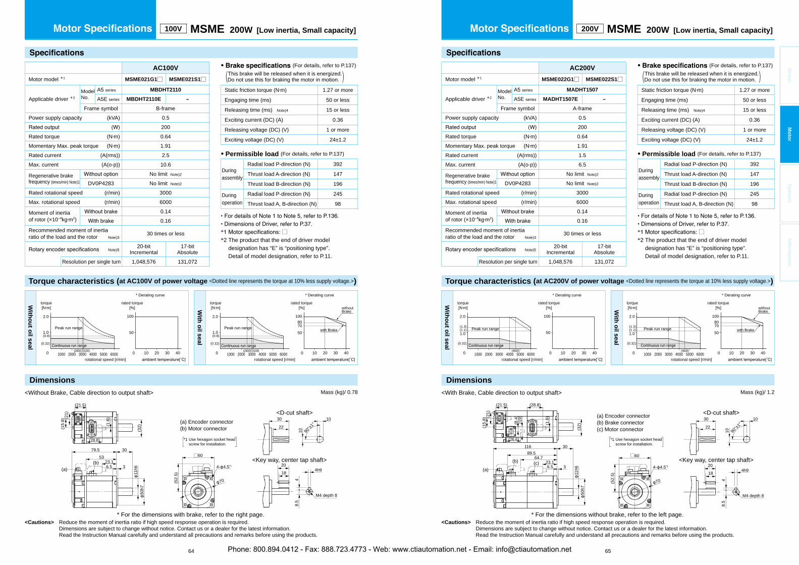
<Cautions> Reduce the moment of inertia ratio if high speed response operation is required. Dimensions are subject to change without notice. Contact us or a dealer for the latest information. Read the Instruction Manual carefully and understand all precautions and remarks before using the products.
* □*2 The product that the end of driver model
designation has “E” is “positioning type”.Detail of model designation, refer to P.11.
<Cautions> Reduce the moment of inertia ratio if high speed response operation is required. Dimensions are subject to change without notice. Contact us or a dealer for the latest information. Read the Instruction Manual carefully and understand all precautions and remarks before using the products.
64 65
* □*2 The product that the end of driver model
designation has “E” is “positioning type”.Detail of model designation, refer to P.11.
Driver
Mo
tor
Op
tion
sIn
form
ation
100V MSME 200W [Low inertia, Small capacity]
AC100V
Motor model *1 MSME021G1□ MSME021S1□
Applicable driver *2ModelNo.
A5 series MBDHT2110
A5E series MBDHT2110E –
Frame symbol B-framePower supply capacity (kVA) 0.5
200Rated torque (N m) 0.64Momentary Max. peak torque (N m) 1.91Rated current (A(rms)) 2.5Max. current (A(o-p)) 10.6
Regenerative brakefrequency (times/min) Note)1
No limit Note)2
DV0P4283 No limit Note)2
Rated rotational speed (r/min) 3000Max. rotational speed (r/min) 6000
Moment of inertiaof rotor (×10 kg m2)
0.140.16
Recommended moment of inertia ratio of the load and the rotor Note)3
30 times or less
Note)520-bit
Incremental17-bit
AbsoluteResolution per single turn 1,048,576 131,072
• (For details, refer to P.137) This brake will be released when it is energized.(Do not use this for braking the motor in motion. )
Static friction torque (N m) 1.27 or more
Engaging time (ms) 50 or less
Releasing time (ms) Note)4 15 or less
Exciting current (DC) (A) 0.36
Releasing voltage (DC) (V) 1 or more
Exciting voltage (DC) (V) 24±1.2
• Permissible load (For details, refer to P.137)
Duringassembly
Radial load P-direction (N) 392
Thrust load A-direction (N) 147
Thrust load B-direction (N) 196
Duringoperation
Radial load P-direction (N) 245
Thrust load A, B-direction (N) 98
200V MSME 200W [Low inertia, Small capacity]
AC200V
Motor model *1 MSME022G1□ MSME022S1□
Applicable driver *2ModelNo.
A5 series MADHT1507
A5E series MADHT1507E –
Frame symbol A-framePower supply capacity (kVA) 0.5
200Rated torque (N m) 0.64Momentary Max. peak torque (N m) 1.91Rated current (A(rms)) 1.5Max. current (A(o-p)) 6.5
Regenerative brakefrequency (times/min) Note)1
No limit Note)2
DV0P4283 No limit Note)2
Rated rotational speed (r/min) 3000Max. rotational speed (r/min) 6000
Moment of inertiaof rotor (×10 kg m2)
0.140.16
Recommended moment of inertia ratio of the load and the rotor Note)3
30 times or less
Note)520-bit
Incremental17-bit
AbsoluteResolution per single turn 1,048,576 131,072
• (For details, refer to P.137) This brake will be released when it is energized.(Do not use this for braking the motor in motion. )
Static friction torque (N m) 1.27 or more
Engaging time (ms) 50 or less
Releasing time (ms) Note)4 15 or less
Exciting current (DC) (A) 0.36
Releasing voltage (DC) (V) 1 or more
Exciting voltage (DC) (V) 24±1.2
• Permissible load (For details, refer to P.137)
Duringassembly
Radial load P-direction (N) 392
Thrust load A-direction (N) 147
Thrust load B-direction (N) 196
Duringoperation
Radial load P-direction (N) 245
Thrust load A, B-direction (N) 98
Mass (kg)/ 1.2Mass (kg)/ 0.78
Torque characteristics (at AC100V of power voltage <Dotted line represents the torque at 10% less supply voltage.>)
With
ou
t oil seal
50
100
100 20 30 40
2.0
(0.8)
(0.32)
(2600) (3100)
1.0
0 1000 2000 3000 4000 5000 6000
torque[N m]
rotational speed [r/min]
Peak run range
rated torque[%]
* Derating curve
With
oil seal
5070
10080
100 20 30 40
2.0
(0.8)
(0.32)
(2600) (3100)
1.0
0 1000 2000 3000 4000 5000 6000
torque[N m]
rotational speed [r/min]
Peak run range with Brake
withoutBrake
rated torque[%]
* Derating curve
With
ou
t oil seal
50
100
100 20 30 40
(0.32)
2.0
(1.3)(1.1)
(4600)
1.0
0 1000 2000 3000 4000 5000 6000
torque[N m]
rotational speed [r/min]
Peak run range
rated torque[%]
* Derating curve
With
oil seal
5070
10080
100 20 30 40
(0.32)
2.0
(1.3)(1.1)
(4600)
1.0
0 1000 2000 3000 4000 5000 6000
torque[N m]
rotational speed [r/min]
Peak run range with Brake
withoutBrake
rated torque[%]
* Derating curve
<Without Brake, Cable direction to output shaft>
* For the dimensions with brake, refer to the right page.
(a) Encoder connector(b) Motor connector
204h9
M4 depth 8
48.
5
18
<D-cut shaft>
<Key way, center tap shaft>
22
30 10
90°±1
°
10
*1 Use hexagon socket head screw for installation.
11h6
(52.
5)
50h7
□60
70
4- 4.5*1
79.5 30
23.153
(21.5)
6.5 3
(28.8)
(15.
8) (21)
(32)(1
.6)
(a)(b)
* For the dimensions without brake, refer to the left page.
<With Brake, Cable direction to output shaft>
(a) Encoder connector(b) Brake connector(c) Motor connector
204h9
48.
5
18
M4 depth 8
<D-cut shaft>
<Key way, center tap shaft>
22
30 10
90°±1
°
10
*1 Use hexagon socket head screw for installation.
11h6
50h7
(52.
5)
□60
70
116 30
6.5 3
(28.8)
89.564.7
23.1
(21.5)
(21)
(15.
8)
(32)
(19)
(8.4
)
(1.6
)
(26.6)
(a)
(b) (c)4- 4.5*1
Torque characteristics (at AC200V of power voltage <Dotted line represents the torque at 10% less supply voltage.>)
DimensionsDimensions
Phone: 800.894.0412 - Fax: 888.723.4773 - Web: www.ctiautomation.net - Email: [email protected]

<Cautions> Reduce the moment of inertia ratio if high speed response operation is required. Dimensions are subject to change without notice. Contact us or a dealer for the latest information. Read the Instruction Manual carefully and understand all precautions and remarks before using the products.
* □*2 The product that the end of driver model
designation has “E” is “positioning type”.Detail of model designation, refer to P.11.
<Cautions> Reduce the moment of inertia ratio if high speed response operation is required. Dimensions are subject to change without notice. Contact us or a dealer for the latest information. Read the Instruction Manual carefully and understand all precautions and remarks before using the products.
66 67
* □*2 The product that the end of driver model
designation has “E” is “positioning type”.Detail of model designation, refer to P.11.
Driver
Mo
tor
Op
tion
sIn
form
ation
100V MSME 400W [Low inertia, Small capacity] 200V MSME 400W [Low inertia, Small capacity]
• (For details, refer to P.137) This brake will be released when it is energized.(Do not use this for braking the motor in motion. )
Static friction torque (N m) 1.27 or more
Engaging time (ms) 50 or less
Releasing time (ms) Note)4 15 or less
Exciting current (DC) (A) 0.36
Releasing voltage (DC) (V) 1 or more
Exciting voltage (DC) (V) 24±1.2
• Permissible load (For details, refer to P.137)
Duringassembly
Radial load P-direction (N) 392
Thrust load A-direction (N) 147
Thrust load B-direction (N) 196
Duringoperation
Radial load P-direction (N) 245
Thrust load A, B-direction (N) 98
AC200V
Motor model *1 MSME042G1□ MSME042S1□
Applicable driver *2ModelNo.
A5 series MBDHT2510
A5E series MBDHT2510E –
Frame symbol B-framePower supply capacity (kVA) 0.9
400Rated torque (N m) 1.3Momentary Max. peak torque (N m) 3.8Rated current (A(rms)) 2.4Max. current (A(o-p)) 10.2
Regenerative brakefrequency (times/min) Note)1
No limit Note)2
DV0P4283 No limit Note)2
Rated rotational speed (r/min) 3000Max. rotational speed (r/min) 6000
Moment of inertiaof rotor (×10 kg m2)
0.260.28
Recommended moment of inertia ratio of the load and the rotor Note)3
30 times or less
Note)520-bit
Incremental17-bit
AbsoluteResolution per single turn 1,048,576 131,072
• (For details, refer to P.137) This brake will be released when it is energized.(Do not use this for braking the motor in motion. )
Static friction torque (N m) 1.27 or more
Engaging time (ms) 50 or less
Releasing time (ms) Note)4 15 or less
Exciting current (DC) (A) 0.36
Releasing voltage (DC) (V) 1 or more
Exciting voltage (DC) (V) 24±1.2
• Permissible load (For details, refer to P.137)
Duringassembly
Radial load P-direction (N) 392
Thrust load A-direction (N) 147
Thrust load B-direction (N) 196
Duringoperation
Radial load P-direction (N) 245
Thrust load A, B-direction (N) 98
AC100V
Motor model *1 MSME041G1□ MSME041S1□
Applicable driver *2ModelNo.
A5 series MCDHT3120
A5E series MCDHT3120E –
Frame symbol C-framePower supply capacity (kVA) 0.9
400Rated torque (N m) 1.3Momentary Max. peak torque (N m) 3.8Rated current (A(rms)) 4.6Max. current (A(o-p)) 19.5
Regenerative brakefrequency (times/min) Note)1
No limit Note)2
DV0P4282 No limit Note)2
Rated rotational speed (r/min) 3000Max. rotational speed (r/min) 6000
Moment of inertiaof rotor (×10 kg m2)
0.260.28
Recommended moment of inertia ratio of the load and the rotor Note)3
30 times or less
Note)520-bit
Incremental17-bit
AbsoluteResolution per single turn 1,048,576 131,072
Mass (kg)/ 1.2 Mass (kg)/ 1.6
Torque characteristics (at AC100V of power voltage <Dotted line represents the torque at 10% less supply voltage.>)
With
ou
t oil seal
50
100
100 20 30 40
4.0
(1.7)
(0.64)
(3100)(3600)
2.0
0 1000 2000 3000 4000 5000 6000
torque[N m]
rotational speed [r/min]
Peak run range
rated torque[%]
* Derating curve
With
oil seal
50
100
100 20 30 40
75
4.0
(1.7)
(0.64)
(3100)(3600)
2.0
0 1000 2000 3000 4000 5000 6000
torque[N m]
rotational speed [r/min]
Peak run range
rated torque[%]
* Derating curve
With
ou
t oil seal
50
10090
100 20 30 40
4.0
(1.7)
(0.32)(2600) (3100)
2.0
0 1000 2000 3000 4000 5000 6000
torque[N m]
rotational speed [r/min]
Peak run range
rated torque[%]
* Derating curve
With
oil seal
50
75
100
100 20 30 40
4.0
(1.7)
(0.32)(2600) (3100)
2.0
0 1000 2000 3000 4000 5000 6000
torque[N m]
rotational speed [r/min]
Peak run range
rated torque[%]
* Derating curve
<Without Brake, Cable direction to output shaft>
* For the dimensions with brake, refer to the right page.
(a) Encoder connector(b) Motor connector
255h9
M5 depth 10
511
22.5
<Key way, center tap shaft>
<D-cut shaft>
22
30 12.5
90°±1
°
12.5
*1 Use hexagon socket head screw for installation.
14h6
(52.
5)
50h7
□6099 30
42.672.5
(21.5)
6.5 3
(28.8)
(15.
8) (21)
(32)
(1.6
)
(a)(b)
70
4- 4.5*1
* For the dimensions without brake, refer to the left page.
<With Brake, Cable direction to output shaft>
255h9
M5 depth 10
511
22.5
(a) Encoder connector(b) Brake connector(c) Motor connector
<Key way, center tap shaft>
<D-cut shaft>
22
30 12.5
90°±1
°
12.5
*1 Use hexagon socket head screw for installation.
14h6
50h7
(52.
5)
□60
135.5 30
6.5 3
(28.8)
10983.9
42.6
(21.5)
(21)
(15.
8)
(32)
(19)
(8.4
)
(1.6
)
(26.6)
(a)
(b) (c)
70
4- 4.5*1
Torque characteristics (at AC200V of power voltage <Dotted line represents the torque at 10% less supply voltage.>)
Dimensions Dimensions
Phone: 800.894.0412 - Fax: 888.723.4773 - Web: www.ctiautomation.net - Email: [email protected]
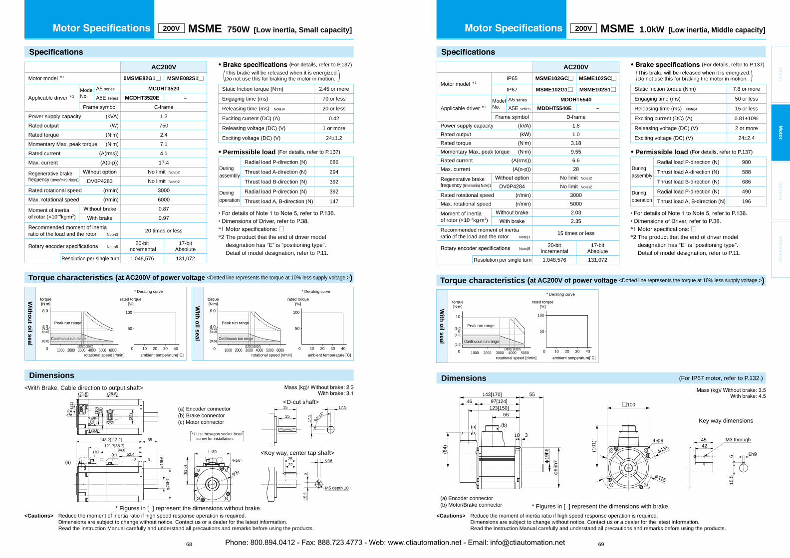
Torque characteristics (at AC200V of power voltage <Dotted line represents the torque at 10% less supply voltage.>)
<Cautions> Reduce the moment of inertia ratio if high speed response operation is required. Dimensions are subject to change without notice. Contact us or a dealer for the latest information. Read the Instruction Manual carefully and understand all precautions and remarks before using the products.
* □*2 The product that the end of driver model
designation has “E” is “positioning type”.Detail of model designation, refer to P.11.
<Cautions> Reduce the moment of inertia ratio if high speed response operation is required. Dimensions are subject to change without notice. Contact us or a dealer for the latest information. Read the Instruction Manual carefully and understand all precautions and remarks before using the products.
68 69
* □*2 The product that the end of driver model
designation has “E” is “positioning type”.Detail of model designation, refer to P.11.
Driver
Mo
tor
Op
tion
sIn
form
ation
200V MSME 1.0kW [Low inertia, Middle capacity]
AC200V
Motor model *1IP65 MSME102GC□ MSME102SC□
IP67 MSME102G1□ MSME102S1□
Applicable driver *2ModelNo.
A5 series MDDHT5540
A5E series MDDHT5540E –
Frame symbol D-framePower supply capacity (kVA) 1.8
1.0Rated torque (N m) 3.18Momentary Max. peak torque (N m) 9.55Rated current (A(rms)) 6.6Max. current (A(o-p)) 28
Regenerative brakefrequency (times/min) Note)1
No limit Note)2
DV0P4284 No limit Note)2
Rated rotational speed (r/min) 3000Max. rotational speed (r/min) 5000
Moment of inertiaof rotor (×10 kg m2)
2.032.35
Recommended moment of inertia ratio of the load and the rotor Note)3
15 times or less
Note)520-bit
Incremental17-bit
AbsoluteResolution per single turn 1,048,576 131,072
• (For details, refer to P.137) This brake will be released when it is energized.(Do not use this for braking the motor in motion. )
Static friction torque (N m) 7.8 or more
Engaging time (ms) 50 or less
Releasing time (ms) Note)4 15 or less
Exciting current (DC) (A) 0.81±10%
Releasing voltage (DC) (V) 2 or more
Exciting voltage (DC) (V) 24±2.4
• Permissible load (For details, refer to P.137)
Duringassembly
Radial load P-direction (N) 980
Thrust load A-direction (N) 588
Thrust load B-direction (N) 686
Duringoperation
Radial load P-direction (N) 490
Thrust load A, B-direction (N) 196
With
oil seal
10
5 50
100
0 1000 2000 3000 4000 5000 100 20 30 40
(4.0)
(1.9)
(6.0)
(4200)(3800)
torque[N m]
rotational speed [r/min]
Peak run range
rated torque[%]
* Derating curve
* Figures in [ ] represent the dimensions with brake.
115
1354542
6h9615
.5
(101
)
□100
4- 9 M3 through
(a) Encoder connector(b) Motor/Brake connector
Key way dimensions
143[170]97[124]46
55
10 3
19h6
123[150]66
95h7
(b)
(84)
(a)
200V MSME 750W [Low inertia, Small capacity]
AC200V
Motor model *1 0MSME82G1□ MSME082S1□
Applicable driver *2ModelNo.
A5 series MCDHT3520
A5E series MCDHT3520E –
Frame symbol C-framePower supply capacity (kVA) 1.3
750Rated torque (N m) 2.4Momentary Max. peak torque (N m) 7.1Rated current (A(rms)) 4.1Max. current (A(o-p)) 17.4
Regenerative brakefrequency (times/min) Note)1
No limit Note)2
DV0P4283 No limit Note)2
Rated rotational speed (r/min) 3000Max. rotational speed (r/min) 6000
Moment of inertiaof rotor (×10 kg m2)
0.870.97
Recommended moment of inertia ratio of the load and the rotor Note)3
20 times or less
Note)520-bit
Incremental17-bit
AbsoluteResolution per single turn 1,048,576 131,072
• (For details, refer to P.137) This brake will be released when it is energized.(Do not use this for braking the motor in motion. )
Static friction torque (N m) 2.45 or more
Engaging time (ms) 70 or less
Releasing time (ms) Note)4 20 or less
Exciting current (DC) (A) 0.42
Releasing voltage (DC) (V) 1 or more
Exciting voltage (DC) (V) 24±1.2
• Permissible load (For details, refer to P.137)
Duringassembly
Radial load P-direction (N) 686
Thrust load A-direction (N) 294
Thrust load B-direction (N) 392
Duringoperation
Radial load P-direction (N) 392
Thrust load A, B-direction (N) 147
With
ou
t oil seal
50
100
100 20 30 40
8.0
(0.6)(3200)(3600)0 1000 2000 3000 4000 5000 6000
torque[N m]
rotational speed [r/min]
Peak run range(3.4)(3.0)4.0
rated torque[%]
* Derating curve
With
oil seal
50
100
100 20 30 40
8.0
(0.6)(3200)(3600)0 1000 2000 3000 4000 5000 6000
torque[N m]
rotational speed [r/min]
Peak run range(3.4)(3.0)4.0
rated torque[%]
* Derating curve
<With Brake, Cable direction to output shaft>
* Figures in [ ] represent the dimensions without brake.
25 6h9
615
.5
22
M5 depth 10
(a) Encoder connector(b) Brake connector(c) Motor connector
<Key way, center tap shaft>
<D-cut shaft>
25
35 17.5
90°±1
°
17.5
*1 Use hexagon socket head screw for installation.
(32)(1
9)(1
0)
(17)
(21)
19h6
70h7
148.2[112.2]
8 3
35
52.494.8
121.7[85.7]
(26.6)
(28.8)(21.5)
(a)
(b) (c)
(61.
6)
□80
4- 6*1
90
Torque characteristics (at AC200V of power voltage <Dotted line represents the torque at 10% less supply voltage.>)
Dimensions Dimensions (For IP67 motor, refer to P.132.)
Phone: 800.894.0412 - Fax: 888.723.4773 - Web: www.ctiautomation.net - Email: [email protected]
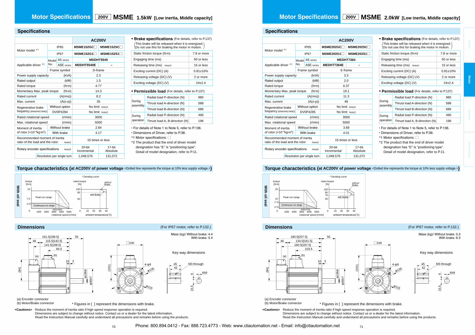
Torque characteristics (at AC200V of power voltage <Dotted line represents the torque at 10% less supply voltage.>)
<Cautions> Reduce the moment of inertia ratio if high speed response operation is required. Dimensions are subject to change without notice. Contact us or a dealer for the latest information. Read the Instruction Manual carefully and understand all precautions and remarks before using the products.
* □*2 The product that the end of driver model
designation has “E” is “positioning type”.Detail of model designation, refer to P.11.
Torque characteristics (at AC200V of power voltage <Dotted line represents the torque at 10% less supply voltage.>)
<Cautions> Reduce the moment of inertia ratio if high speed response operation is required. Dimensions are subject to change without notice. Contact us or a dealer for the latest information. Read the Instruction Manual carefully and understand all precautions and remarks before using the products.
70 71
* □*2 The product that the end of driver model
designation has “E” is “positioning type”.Detail of model designation, refer to P.11.
Driver
Mo
tor
Op
tion
sIn
form
ation
200V MSME 1.5kW [Low inertia, Middle capacity]
AC200V
Motor model *1IP65 MSME152GC□ MSME152SC□
IP67 MSME152G1□ MSME152S1□
Applicable driver *2ModelNo.
A5 series MDDHT5540
A5E series MDDHT5540E –
Frame symbol D-framePower supply capacity (kVA) 2.3
1.5Rated torque (N m) 4.77Momentary Max. peak torque (N m) 14.3Rated current (A(rms)) 8.2Max. current (A(o-p)) 35
Regenerative brakefrequency (times/min) Note)1
No limit Note)2
DV0P4284 No limit Note)2
Rated rotational speed (r/min) 3000Max. rotational speed (r/min) 5000
Moment of inertiaof rotor (×10 kg m2)
2.843.17
Recommended moment of inertia ratio of the load and the rotor Note)3
15 times or less
Note)520-bit
Incremental17-bit
AbsoluteResolution per single turn 1,048,576 131,072
• (For details, refer to P.137) This brake will be released when it is energized.(Do not use this for braking the motor in motion. )
Static friction torque (N m) 7.8 or more
Engaging time (ms) 50 or less
Releasing time (ms) Note)4 15 or less
Exciting current (DC) (A) 0.81±10%
Releasing voltage (DC) (V) 2 or more
Exciting voltage (DC) (V) 24±2.4
• Permissible load (For details, refer to P.137)
Duringassembly
Radial load P-direction (N) 980
Thrust load A-direction (N) 588
Thrust load B-direction (N) 686
Duringoperation
Radial load P-direction (N) 490
Thrust load A, B-direction (N) 196
With
oil seal
50
100
100 20 30 40(3600)(3200)0
85
1000 2000 3000 4000 5000
15
7.5
(4.0)
torque[N m]
rotational speed [r/min]
Peak run rangewith Brake
withoutBrake
rated torque[%]
* Derating curve
* Figures in [ ] represent the dimensions with brake.
115
1354542
6h9615
.5
(101
)
□100
4- 9 M3 through
(a) Encoder connector(b) Motor/Brake connector
Key way dimensions
(84)
(a)
161.5[188.5]115.5[142.5]46
55
10 3
19h6
141.5[168.5]84.5
(b)
95h7
AC200V
Motor model *1IP65 MSME202GC□ MSME202SC□
IP67 MSME202G1□ MSME202S1□
Applicable driver *2ModelNo.
A5 series MEDHT7364
A5E series MEDHT7364E –
Frame symbol E-framePower supply capacity (kVA) 3.3
2.0Rated torque (N m) 6.37Momentary Max. peak torque (N m) 19.1Rated current (A(rms)) 11.3Max. current (A(o-p)) 48
Regenerative brakefrequency (times/min) Note)1
No limit Note)2
DV0P4285 No limit Note)2
Rated rotational speed (r/min) 3000Max. rotational speed (r/min) 5000
Moment of inertiaof rotor (×10 kg m2)
3.684.01
Recommended moment of inertia ratio of the load and the rotor Note)3
15 times or less
Note)520-bit
Incremental17-bit
AbsoluteResolution per single turn 1,048,576 131,072
• (For details, refer to P.137) This brake will be released when it is energized.(Do not use this for braking the motor in motion. )
Static friction torque (N m) 7.8 or more
Engaging time (ms) 50 or less
Releasing time (ms) Note)4 15 or less
Exciting current (DC) (A) 0.81±10%
Releasing voltage (DC) (V) 2 or more
Exciting voltage (DC) (V) 24±2.4
• Permissible load (For details, refer to P.137)
Duringassembly
Radial load P-direction (N) 980
Thrust load A-direction (N) 588
Thrust load B-direction (N) 686
Duringoperation
Radial load P-direction (N) 490
Thrust load A, B-direction (N) 196
200V MSME 2.0kW [Low inertia, Middle capacity]
With
oil seal
50
100
100 20 30 400
8570
1000 2000 3000 4000 5000
20
10(7.0)
(2.0)(3700)(3300)
torque[N m]
rotational speed [r/min]
Peak run range with Brake
withoutBrake
rated torque[%]
* Derating curve
* Figures in [ ] represent the dimensions with brake.
4542
6h9
15.5
M3 through
6
(a) Encoder connector(b) Motor/Brake connector
Key way dimensions
115
135(101
)
□100
4- 9
180.5[207.5]134.5[161.5]46
55
10 3
19h6
160.5[187.5]103.5
(b)
95h7
(84)
(a)
Dimensions (For IP67 motor, refer to P.132.) Dimensions (For IP67 motor, refer to P.132.)
Phone: 800.894.0412 - Fax: 888.723.4773 - Web: www.ctiautomation.net - Email: [email protected]

Torque characteristics (at AC200V of power voltage <Dotted line represents the torque at 10% less supply voltage.>)
<Cautions> Reduce the moment of inertia ratio if high speed response operation is required. Dimensions are subject to change without notice. Contact us or a dealer for the latest information. Read the Instruction Manual carefully and understand all precautions and remarks before using the products.
* □*2 The product that the end of driver model
designation has “E” is “positioning type”.Detail of model designation, refer to P.11.
Torque characteristics (at AC200V of power voltage <Dotted line represents the torque at 10% less supply voltage.>)
<Cautions> Reduce the moment of inertia ratio if high speed response operation is required. Dimensions are subject to change without notice. Contact us or a dealer for the latest information. Read the Instruction Manual carefully and understand all precautions and remarks before using the products.
72 73
* □*2 The product that the end of driver model
designation has “E” is “positioning type”.Detail of model designation, refer to P.11.
Driver
Mo
tor
Op
tion
sIn
form
ation
200V MSME 3.0kW [Low inertia, Middle capacity]
• (For details, refer to P.137) This brake will be released when it is energized.(Do not use this for braking the motor in motion. )
Static friction torque (N m) 11.8 or more
Engaging time (ms) 80 or less
Releasing time (ms) Note)4 15 or less
Exciting current (DC) (A) 0.81±10%
Releasing voltage (DC) (V) 2 or more
Exciting voltage (DC) (V) 24±2.4
• Permissible load (For details, refer to P.137)
Duringassembly
Radial load P-direction (N) 980
Thrust load A-direction (N) 588
Thrust load B-direction (N) 686
Duringoperation
Radial load P-direction (N) 490
Thrust load A, B-direction (N) 196
AC200V
Motor model *1IP65 MSME302GC□ MSME302SC□
IP67 MSME302G1□ MSME302S1□
Applicable driver *2ModelNo.
A5 series MFDHTA390
A5E series MFDHTA390E –
Frame symbol F-framePower supply capacity (kVA) 4.5
3.0Rated torque (N m) 9.55Momentary Max. peak torque (N m) 28.6Rated current (A(rms)) 18.1Max. current (A(o-p)) 77
Regenerative brakefrequency (times/min) Note)1
No limit Note)2
DV0P4285×2 No limit Note)2
Rated rotational speed (r/min) 3000Max. rotational speed (r/min) 5000
Moment of inertiaof rotor (×10 kg m2)
6.507.85
Recommended moment of inertia ratio of the load and the rotor Note)3
15 times or less
Note)520-bit
Incremental17-bit
AbsoluteResolution per single turn 1,048,576 131,072
With
oil seal
50
100
100 20 30 400
9085
1000 2000 3000 4000 5000
30
15(12)(8.0)(5.7)
(3400)(3100)
torque[N m]
rotational speed [r/min]
Peak run range with Brake
withoutBrake
rated torque[%]
* Derating curve
* Figures in [ ] represent the dimensions with brake.
M3 through
(113
) 4- 9
□120
145162
4541
8h9718
(a) Encoder connector(b) Motor/Brake connector
Key way dimensions
46192[217] 55
12 3
110h
7
146[171]
22h6
172[197]112
(84)
(a)(b)
200V MSME 4.0kW [Low inertia, Middle capacity]
AC200V
Motor model *1IP65 MSME402GC□ MSME402SC□
IP67 MSME402G1□ MSME402S1□
Applicable driver *2ModelNo.
A5 series MFDHTB3A2
A5E series MFDHTB3A2E –
Frame symbol F-framePower supply capacity (kVA) 6.0
4.0Rated torque (N m) 12.7Momentary Max. peak torque (N m) 38.2Rated current (A(rms)) 19.6Max. current (A(o-p)) 83
Regenerative brakefrequency (times/min) Note)1
No limit Note)2
DV0P4285×2 No limit Note)2
Rated rotational speed (r/min) 3000Max. rotational speed (r/min) 4500
Moment of inertiaof rotor (×10 kg m2)
12.914.2
Recommended moment of inertia ratio of the load and the rotor Note)3
15 times or less
Note)520-bit
Incremental17-bit
AbsoluteResolution per single turn 1,048,576 131,072
• (For details, refer to P.137) This brake will be released when it is energized.(Do not use this for braking the motor in motion. )
Static friction torque (N m) 16.2 or more
Engaging time (ms) 110 or less
Releasing time (ms) Note)4 50 or less
Exciting current (DC) (A) 0.90±10%
Releasing voltage (DC) (V) 2 or more
Exciting voltage (DC) (V) 24±2.4
• Permissible load (For details, refer to P.137)
Duringassembly
Radial load P-direction (N) 980
Thrust load A-direction (N) 588
Thrust load B-direction (N) 686
Duringoperation
Radial load P-direction (N) 784
Thrust load A, B-direction (N) 343
With
oil seal
50
100
100 20 30 400
9085
1000 2000 3000 4000 5000
40
20
(10)
(3100)(2800)
torque[N m]
rotational speed [r/min]
Peak run range with Brake
withoutBrake
rated torque[%]
* Derating curve
* Figures in [ ] represent the dimensions with brake.
M3 through
(118
) 4- 9
□130
145 165
5551
8h9720
(a) Encoder connector(b) Motor/Brake connector
Key way dimensions
46210[235] 65
12 6
110h
7
164[189]
24h6
190[215]127
(b)
(84)
(a)
Dimensions (For IP67 motor, refer to P.132.) Dimensions (For IP67 motor, refer to P.132.)
Phone: 800.894.0412 - Fax: 888.723.4773 - Web: www.ctiautomation.net - Email: [email protected]
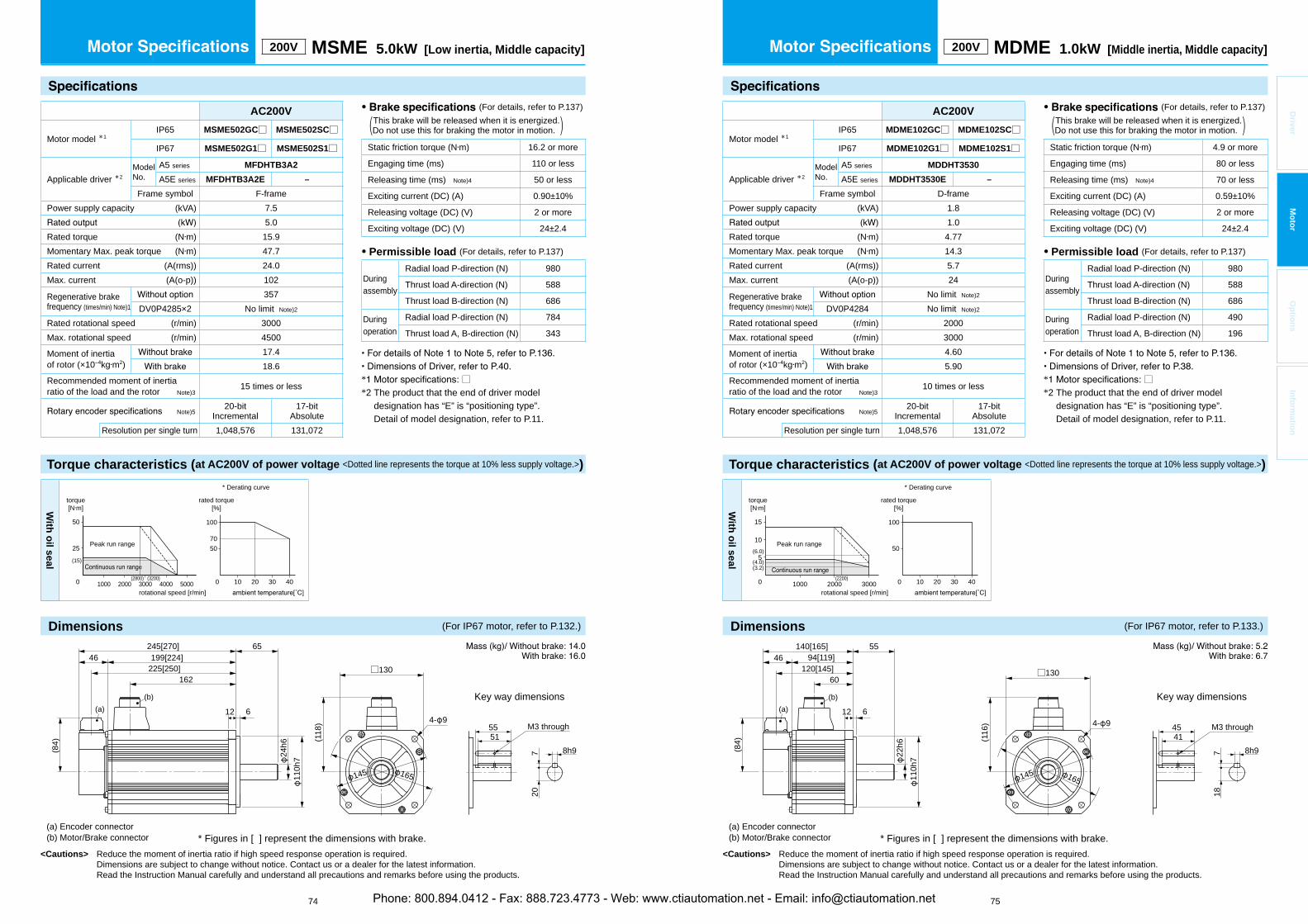
Torque characteristics (at AC200V of power voltage <Dotted line represents the torque at 10% less supply voltage.>)
<Cautions> Reduce the moment of inertia ratio if high speed response operation is required. Dimensions are subject to change without notice. Contact us or a dealer for the latest information. Read the Instruction Manual carefully and understand all precautions and remarks before using the products.
* □*2 The product that the end of driver model
designation has “E” is “positioning type”.Detail of model designation, refer to P.11.
Torque characteristics (at AC200V of power voltage <Dotted line represents the torque at 10% less supply voltage.>)
<Cautions> Reduce the moment of inertia ratio if high speed response operation is required. Dimensions are subject to change without notice. Contact us or a dealer for the latest information. Read the Instruction Manual carefully and understand all precautions and remarks before using the products.
74 75
* □*2 The product that the end of driver model
designation has “E” is “positioning type”.Detail of model designation, refer to P.11.
Driver
Mo
tor
Op
tion
sIn
form
ation
200V MSME 5.0kW [Low inertia, Middle capacity]
• (For details, refer to P.137) This brake will be released when it is energized.(Do not use this for braking the motor in motion. )
Static friction torque (N m) 16.2 or more
Engaging time (ms) 110 or less
Releasing time (ms) Note)4 50 or less
Exciting current (DC) (A) 0.90±10%
Releasing voltage (DC) (V) 2 or more
Exciting voltage (DC) (V) 24±2.4
• Permissible load (For details, refer to P.137)
Duringassembly
Radial load P-direction (N) 980
Thrust load A-direction (N) 588
Thrust load B-direction (N) 686
Duringoperation
Radial load P-direction (N) 784
Thrust load A, B-direction (N) 343
AC200V
Motor model *1IP65 MSME502GC□ MSME502SC□
IP67 MSME502G1□ MSME502S1□
Applicable driver *2ModelNo.
A5 series MFDHTB3A2
A5E series MFDHTB3A2E –
Frame symbol F-framePower supply capacity (kVA) 7.5
5.0Rated torque (N m) 15.9Momentary Max. peak torque (N m) 47.7Rated current (A(rms)) 24.0Max. current (A(o-p)) 102
Regenerative brakefrequency (times/min) Note)1
357DV0P4285×2 No limit Note)2
Rated rotational speed (r/min) 3000Max. rotational speed (r/min) 4500
Moment of inertiaof rotor (×10 kg m2)
17.418.6
Recommended moment of inertia ratio of the load and the rotor Note)3
15 times or less
Note)520-bit
Incremental17-bit
AbsoluteResolution per single turn 1,048,576 131,072
With
oil seal
50
100
100 20 30 400
70
1000 2000 3000 4000 5000
50
25
(15)
(3200)(2800)
torque[N m]
rotational speed [r/min]
Peak run range
rated torque[%]
* Derating curve
* Figures in [ ] represent the dimensions with brake.
M3 through
(118
) 4- 9
□130
145 165
5551
8h9720
(a) Encoder connector(b) Motor/Brake connector
Key way dimensions
46245[270] 65
12 6
110h
7
199[224]
24h6
225[250]162
(b)
(84)
(a)
200V MDME 1.0kW [Middle inertia, Middle capacity]
AC200V
Motor model *1IP65 MDME102GC□ MDME102SC□
IP67 MDME102G1□ MDME102S1□
Applicable driver *2ModelNo.
A5 series MDDHT3530
A5E series MDDHT3530E –
Frame symbol D-framePower supply capacity (kVA) 1.8
1.0Rated torque (N m) 4.77Momentary Max. peak torque (N m) 14.3Rated current (A(rms)) 5.7Max. current (A(o-p)) 24
Regenerative brakefrequency (times/min) Note)1
No limit Note)2
DV0P4284 No limit Note)2
Rated rotational speed (r/min) 2000Max. rotational speed (r/min) 3000
Moment of inertiaof rotor (×10 kg m2)
4.605.90
Recommended moment of inertia ratio of the load and the rotor Note)3
10 times or less
Note)520-bit
Incremental17-bit
AbsoluteResolution per single turn 1,048,576 131,072
• (For details, refer to P.137) This brake will be released when it is energized.(Do not use this for braking the motor in motion. )
Static friction torque (N m) 4.9 or more
Engaging time (ms) 80 or less
Releasing time (ms) Note)4 70 or less
Exciting current (DC) (A) 0.59±10%
Releasing voltage (DC) (V) 2 or more
Exciting voltage (DC) (V) 24±2.4
• Permissible load (For details, refer to P.137)
Duringassembly
Radial load P-direction (N) 980
Thrust load A-direction (N) 588
Thrust load B-direction (N) 686
Duringoperation
Radial load P-direction (N) 490
Thrust load A, B-direction (N) 196
With
oil seal
50
100
100 20 30 400 1000 2000 3000
15
10
5
(2200)
(6.0)
(4.0)(3.2)
torque[N m]
rotational speed [r/min]
Peak run range
rated torque[%]
* Derating curve
* Figures in [ ] represent the dimensions with brake.
M3 through
Key way dimensions
(116
) 4- 9
□130
165
4541
8h9718
145
(a) Encoder connector(b) Motor/Brake connector
46140[165] 55
12 6
94[119]
22h6
120[145]60
(b)
110h
7
(a)
(84)
Dimensions (For IP67 motor, refer to P.132.) Dimensions (For IP67 motor, refer to P.133.)
Phone: 800.894.0412 - Fax: 888.723.4773 - Web: www.ctiautomation.net - Email: [email protected]

Torque characteristics (at AC200V of power voltage <Dotted line represents the torque at 10% less supply voltage.>)
<Cautions> Reduce the moment of inertia ratio if high speed response operation is required. Dimensions are subject to change without notice. Contact us or a dealer for the latest information. Read the Instruction Manual carefully and understand all precautions and remarks before using the products.
* □*2 The product that the end of driver model
designation has “E” is “positioning type”.Detail of model designation, refer to P.11.
Torque characteristics (at AC200V of power voltage <Dotted line represents the torque at 10% less supply voltage.>)
<Cautions> Reduce the moment of inertia ratio if high speed response operation is required. Dimensions are subject to change without notice. Contact us or a dealer for the latest information. Read the Instruction Manual carefully and understand all precautions and remarks before using the products.
76 77
* □*2 The product that the end of driver model
designation has “E” is “positioning type”.Detail of model designation, refer to P.11.
Driver
Mo
tor
Op
tion
sIn
form
ation
200V MDME 1.5kW [Middle inertia, Middle capacity]
• (For details, refer to P.137) This brake will be released when it is energized.(Do not use this for braking the motor in motion. )
Static friction torque (N m) 13.7 or more
Engaging time (ms) 100 or less
Releasing time (ms) Note)4 50 or less
Exciting current (DC) (A) 0.79±10%
Releasing voltage (DC) (V) 2 or more
Exciting voltage (DC) (V) 24±2.4
• Permissible load (For details, refer to P.137)
Duringassembly
Radial load P-direction (N) 980
Thrust load A-direction (N) 588
Thrust load B-direction (N) 686
Duringoperation
Radial load P-direction (N) 490
Thrust load A, B-direction (N) 196
AC200V
Motor model *1IP65 MDME152GC□ MDME152SC□
IP67 MDME152G1□ MDME152S1□
Applicable driver *2ModelNo.
A5 series MDDHT5540
A5E series MDDHT5540E –
Frame symbol D-framePower supply capacity (kVA) 2.3
1.5Rated torque (N m) 7.16Momentary Max. peak torque (N m) 21.5Rated current (A(rms)) 9.4Max. current (A(o-p)) 40
Regenerative brakefrequency (times/min) Note)1
No limit Note)2
DV0P4284 No limit Note)2
Rated rotational speed (r/min) 2000Max. rotational speed (r/min) 3000
Moment of inertiaof rotor (×10 kg m2)
6.707.99
Recommended moment of inertia ratio of the load and the rotor Note)3
10 times or less
Note)520-bit
Incremental17-bit
AbsoluteResolution per single turn 1,048,576 131,072
With
oil seal
50
100
100 20 30 40(2300)0 1000 2000 3000
20
10(6.0)(4.8)
torque[N m]
rotational speed [r/min]
Peak run range
rated torque[%]
* Derating curve
* Figures in [ ] represent the dimensions with brake.
M3 through
(116
) 4- 9
□130
165
4541
8h9718
145
(a) Encoder connector(b) Motor/Brake connector
Key way dimensions(a)
(84)
46157.5[182.5] 55
12 6
111.5[136.5]
22h6
137.5[162.5]77.5
(b)
110h
7
200V MDME 2.0kW [Middle inertia, Middle capacity]
• (For details, refer to P.137) This brake will be released when it is energized.(Do not use this for braking the motor in motion. )
Static friction torque (N m) 13.7 or more
Engaging time (ms) 100 or less
Releasing time (ms) Note)4 50 or less
Exciting current (DC) (A) 0.79±10%
Releasing voltage (DC) (V) 2 or more
Exciting voltage (DC) (V) 24±2.4
• Permissible load (For details, refer to P.137)
Duringassembly
Radial load P-direction (N) 980
Thrust load A-direction (N) 588
Thrust load B-direction (N) 686
Duringoperation
Radial load P-direction (N) 490
Thrust load A, B-direction (N) 196
AC200V
Motor model *1IP65 MDME202GC□ MDME202SC□
IP67 MDME202G1□ MDME202S1□
Applicable driver *2ModelNo.
A5 series MEDHT7364
A5E series MEDHT7364E –
Frame symbol E-framePower supply capacity (kVA) 3.3
2.0Rated torque (N m) 9.55Momentary Max. peak torque (N m) 28.6Rated current (A(rms)) 11.5Max. current (A(o-p)) 49
Regenerative brakefrequency (times/min) Note)1
No limit Note)2
DV0P4285 No limit Note)2
Rated rotational speed (r/min) 2000Max. rotational speed (r/min) 3000
Moment of inertiaof rotor (×10 kg m2)
8.7210.0
Recommended moment of inertia ratio of the load and the rotor Note)3
10 times or less
Note)520-bit
Incremental17-bit
AbsoluteResolution per single turn 1,048,576 131,072
With
oil seal
50
100
100 20 30 400 1000 2000 3000
30
15
(2200)
(11)(6.4)
torque[N m]
rotational speed [r/min]
Peak run range
rated torque[%]
* Derating curve
* Figures in [ ] represent the dimensions with brake.
M3 through
(116
) 4- 9
□130
165
4541
8h9718
145
(a) Encoder connector(b) Motor/Brake connector
Key way dimensions
46175[200] 55
12 6
129[154]
22h6
155[180]95
(b)
110h
7
(a)
(84)
Dimensions (For IP67 motor, refer to P.133.) Dimensions (For IP67 motor, refer to P.133.)
Phone: 800.894.0412 - Fax: 888.723.4773 - Web: www.ctiautomation.net - Email: [email protected]

Torque characteristics (at AC200V of power voltage <Dotted line represents the torque at 10% less supply voltage.>)
<Cautions> Reduce the moment of inertia ratio if high speed response operation is required. Dimensions are subject to change without notice. Contact us or a dealer for the latest information. Read the Instruction Manual carefully and understand all precautions and remarks before using the products.
* □*2 The product that the end of driver model
designation has “E” is “positioning type”.Detail of model designation, refer to P.11.
Torque characteristics (at AC200V of power voltage <Dotted line represents the torque at 10% less supply voltage.>)
<Cautions> Reduce the moment of inertia ratio if high speed response operation is required. Dimensions are subject to change without notice. Contact us or a dealer for the latest information. Read the Instruction Manual carefully and understand all precautions and remarks before using the products.
78 79
* □*2 The product that the end of driver model
designation has “E” is “positioning type”.Detail of model designation, refer to P.11.
Driver
Mo
tor
Op
tion
sIn
form
ation
200V MDME 3.0kW [Middle inertia, Middle capacity]
• (For details, refer to P.137) This brake will be released when it is energized.(Do not use this for braking the motor in motion. )
Static friction torque (N m) 16.2 or more
Engaging time (ms) 110 or less
Releasing time (ms) Note)4 50 or less
Exciting current (DC) (A) 0.90±10%
Releasing voltage (DC) (V) 2 or more
Exciting voltage (DC) (V) 24±2.4
• Permissible load (For details, refer to P.137)
Duringassembly
Radial load P-direction (N) 980
Thrust load A-direction (N) 588
Thrust load B-direction (N) 686
Duringoperation
Radial load P-direction (N) 784
Thrust load A, B-direction (N) 343
AC200V
Motor model *1IP65 MDME302GC□ MDME302SC□
IP67 MDME302G1□ MDME302S1□
Applicable driver *2ModelNo.
A5 series MFDHTA390
A5E series MFDHTA390E –
Frame symbol F-framePower supply capacity (kVA) 4.5
3.0Rated torque (N m) 14.3Momentary Max. peak torque (N m) 43.0Rated current (A(rms)) 17.4Max. current (A(o-p)) 74
Regenerative brakefrequency (times/min) Note)1
No limit Note)2
DV0P4285×2 No limit Note)2
Rated rotational speed (r/min) 2000Max. rotational speed (r/min) 3000
Moment of inertiaof rotor (×10 kg m2)
12.914.2
Recommended moment of inertia ratio of the load and the rotor Note)3
10 times or less
Note)520-bit
Incremental17-bit
AbsoluteResolution per single turn 1,048,576 131,072
With
oil seal
50
100
100 20 30 400 1000 2000 3000
50
25(28)
(20)
(9.5)(2200)(2400)
torque[N m]
rotational speed [r/min]
Peak run range
rated torque[%]
* Derating curve
* Figures in [ ] represent the dimensions with brake.
M3 through
(118
) 4- 9
□130
165
5551
8h9720
145
(a) Encoder connector(b) Motor/Brake connector
Key way dimensions
46210[235] 65
12 6
164[189]
24h6
190[215]127
(b)
110h
7
(a)
(84)
200V MDME 4.0kW [Middle inertia, Middle capacity]
• (For details, refer to P.137) This brake will be released when it is energized.(Do not use this for braking the motor in motion. )
Static friction torque (N m) 24.5 or more
Engaging time (ms) 80 or less
Releasing time (ms) Note)4 25 or less
Exciting current (DC) (A) 1.3±10%
Releasing voltage (DC) (V) 2 or more
Exciting voltage (DC) (V) 24±2.4
• Permissible load (For details, refer to P.137)
Duringassembly
Radial load P-direction (N) 1666
Thrust load A-direction (N) 784
Thrust load B-direction (N) 980
Duringoperation
Radial load P-direction (N) 784
Thrust load A, B-direction (N) 343
AC200V
Motor model *1IP65 MDME402GC□ MDME402SC□
IP67 MDME402G1□ MDME402S1□
Applicable driver *2ModelNo.
A5 series MFDHTB3A2
A5E series MFDHTB3A2E –
Frame symbol F-framePower supply capacity (kVA) 6.0
4.0Rated torque (N m) 19.1Momentary Max. peak torque (N m) 57.3Rated current (A(rms)) 21.0Max. current (A(o-p)) 89
Regenerative brakefrequency (times/min) Note)1
No limit Note)2
DV0P4285×2 No limit Note)2
Rated rotational speed (r/min) 2000Max. rotational speed (r/min) 3000
Moment of inertiaof rotor (×10 kg m2)
37.638.6
Recommended moment of inertia ratio of the load and the rotor Note)3
10 times or less
Note)520-bit
Incremental17-bit
AbsoluteResolution per single turn 1,048,576 131,072
With
oil seal
50
100
100 20 30 400 1000 2000 3000
50
25
(13)
(1900)(2100)
torque[N m]
rotational speed [r/min]
Peak run range
rated torque[%]
* Derating curve
* Figures in [ ] represent the dimensions with brake.
M3 through
(140
)
4- 13.5
□176
5550
10h9830
200233
(a) Encoder connector(b) Motor/Brake connector
Key way dimensions
46179[204] 70
18 3.2
114.
3h7
133[158]
35h6
159[184]96
(84)
(a)
(b)
Dimensions (For IP67 motor, refer to P.133.) Dimensions (For IP67 motor, refer to P.133.)
Phone: 800.894.0412 - Fax: 888.723.4773 - Web: www.ctiautomation.net - Email: [email protected]

Torque characteristics (at AC200V of power voltage <Dotted line represents the torque at 10% less supply voltage.>)
Dimensions
<Cautions> Reduce the moment of inertia ratio if high speed response operation is required. Dimensions are subject to change without notice. Contact us or a dealer for the latest information. Read the Instruction Manual carefully and understand all precautions and remarks before using the products.
* □*2 The product that the end of driver model
designation has “E” is “positioning type”.Detail of model designation, refer to P.11.
Torque characteristics (at AC200V of power voltage <Dotted line represents the torque at 10% less supply voltage.>)
<Cautions> Reduce the moment of inertia ratio if high speed response operation is required. Dimensions are subject to change without notice. Contact us or a dealer for the latest information. Read the Instruction Manual carefully and understand all precautions and remarks before using the products.
80 81
* □*2 The product that the end of driver model
designation has “E” is “positioning type”.Detail of model designation, refer to P.11.
Driver
Mo
tor
Op
tion
sIn
form
ation
200V MDME 5.0kW [Middle inertia, Middle capacity]
• (For details, refer to P.137) This brake will be released when it is energized.(Do not use this for braking the motor in motion. )
Static friction torque (N m) 24.5 or more
Engaging time (ms) 80 or less
Releasing time (ms) Note)4 25 or less
Exciting current (DC) (A) 1.3±10%
Releasing voltage (DC) (V) 2 or more
Exciting voltage (DC) (V) 24±2.4
• Permissible load (For details, refer to P.137)
Duringassembly
Radial load P-direction (N) 1666
Thrust load A-direction (N) 784
Thrust load B-direction (N) 980
Duringoperation
Radial load P-direction (N) 784
Thrust load A, B-direction (N) 343
AC200V
Motor model *1IP65 MDME502GC□ MDME502SC□
IP67 MDME502G1□ MDME502S1□
Applicable driver *2ModelNo.
A5 series MFDHTB3A2
A5E series MFDHTB3A2E –
Frame symbol F-framePower supply capacity (kVA) 7.5
5.0Rated torque (N m) 23.9Momentary Max. peak torque (N m) 71.6Rated current (A(rms)) 25.9Max. current (A(o-p)) 110
Regenerative brakefrequency (times/min) Note)1
120DV0P4285×2 No limit Note)2
Rated rotational speed (r/min) 2000Max. rotational speed (r/min) 3000
Moment of inertiaof rotor (×10 kg m2)
48.048.8
Recommended moment of inertia ratio of the load and the rotor Note)3
10 times or less
Note)520-bit
Incremental17-bit
AbsoluteResolution per single turn 1,048,576 131,072
With
oil seal
50
1009085
100 20 30 400 1000 2000 3000
70
35(20)(3)
(1900)(2100)
torque[N m]
rotational speed [r/min]
Peak run range with Brake
withoutBrake
rated torque[%]
* Derating curve
* Figures in [ ] represent the dimensions with brake.
M3 through
(140
)
4- 13.5
□176
5550
10h9830
200233
(a) Encoder connector(b) Motor/Brake connector
Key way dimensions
(84)
(a)
46198[223] 70
18 3.2
152[177]178[203]
115(b)
114.
3h7
35h6
200V MDME 7.5kW [Middle inertia, Middle capacity]
AC200V
Motor model *1IP65 – –
IP67 MDME752G1□ MDME752S1□
Applicable driver *2ModelNo.
A5 series MGDHTC3B4
A5E series – –
Frame symbol G-framePower supply capacity (kVA) 11
7.5Rated torque (N m) 47.8Momentary Max. peak torque (N m) 119Rated current (A(rms)) 44.0Max. current (A(o-p)) 165
Regenerative brakefrequency (times/min) Note)1
No limit Note)2
DV0P4285×3 No limit Note)2
Rated rotational speed (r/min) 1500Max. rotational speed (r/min) 3000
Moment of inertiaof rotor (×10 kg m2)
101107
Recommended moment of inertia ratio of the load and the rotor Note)3
10 times or less
Note)520-bit
Incremental17-bit
AbsoluteResolution per single turn 1,048,576 131,072
(a) Encoder connector (b) Motor/ connector(c) Brake connector (only with brake)
Key way dimensions
M4 through
(184
) 4- 13.5
□176
9690
12h9837
200233
* Figures in [ ] represent the dimensions with brake.
(b)
(a)(6
0)
44312[337] 113
24 3.2
268[293]290[315]
219[253]
48
(c)
114.
3h7
42h6
Eye bolt(Thread 10)
With
oil seal
90
(47.8)
(60)
(12)
50
100
100 20 30 400 1000 2000 3000(2500)(2200)
50
100(119)
(1500)
torque[N m]
rotational speed [r/min]
Peak run range
rated torque[%]
* Derating curve
Dimensions (For IP67 motor, refer to P.133.)
• (For details, refer to P.137) This brake will be released when it is energized.(Do not use this for braking the motor in motion. )
Static friction torque (N m) 58.8 or more
Engaging time (ms) 150 or less
Releasing time (ms) Note)4 50 or less
Exciting current (DC) (A) 1.4±10%
Releasing voltage (DC) (V) 2 or more
Exciting voltage (DC) (V) 24±2.4
• Permissible load (For details, refer to P.137)
Duringassembly
Radial load P-direction (N) 2058
Thrust load A-direction (N) 980
Thrust load B-direction (N) 1176
Duringoperation
Radial load P-direction (N) 1176
Thrust load A, B-direction (N) 490
Phone: 800.894.0412 - Fax: 888.723.4773 - Web: www.ctiautomation.net - Email: [email protected]
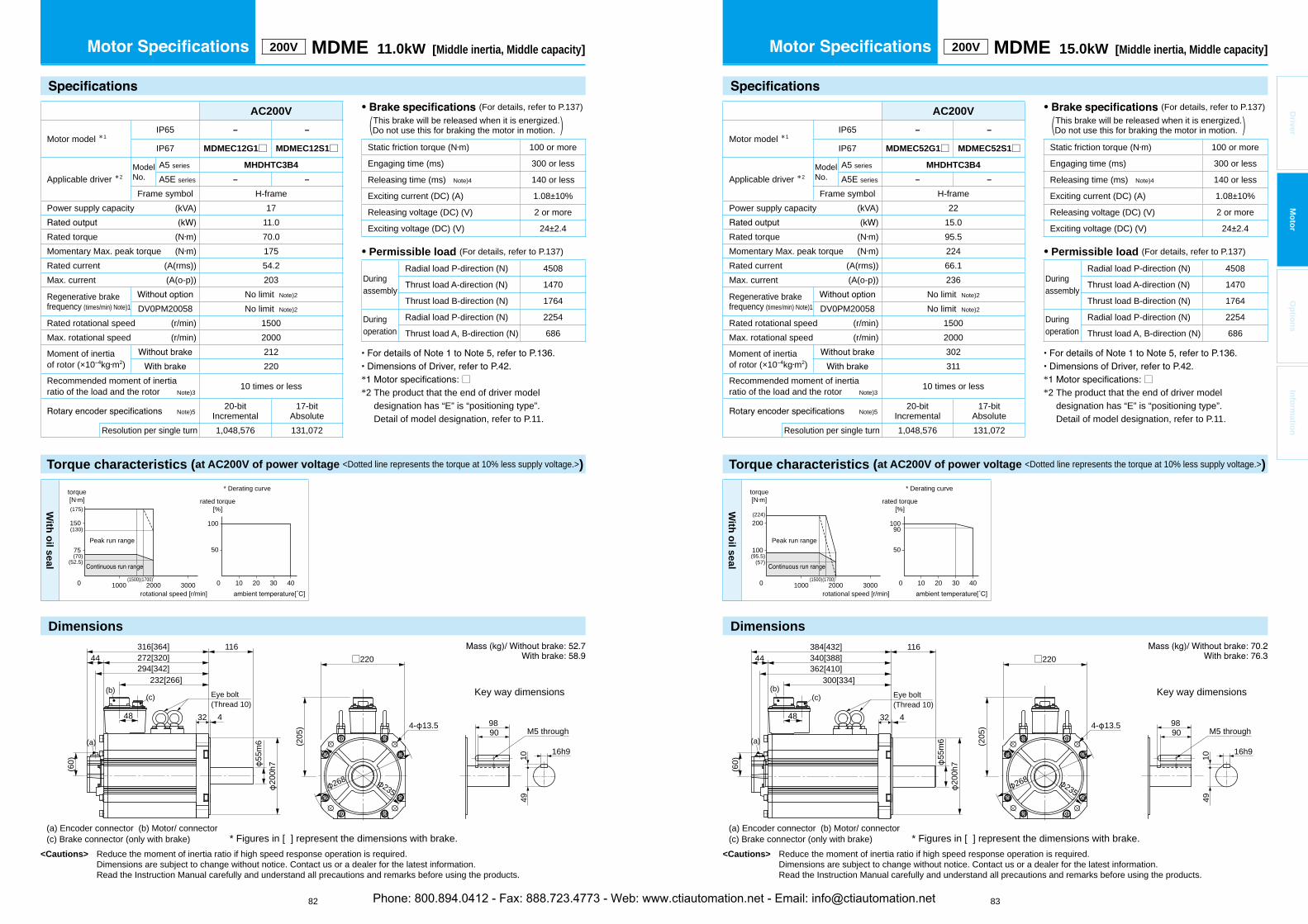
Torque characteristics (at AC200V of power voltage <Dotted line represents the torque at 10% less supply voltage.>)
Dimensions
<Cautions> Reduce the moment of inertia ratio if high speed response operation is required. Dimensions are subject to change without notice. Contact us or a dealer for the latest information. Read the Instruction Manual carefully and understand all precautions and remarks before using the products.
* □*2 The product that the end of driver model
designation has “E” is “positioning type”.Detail of model designation, refer to P.11.
Torque characteristics (at AC200V of power voltage <Dotted line represents the torque at 10% less supply voltage.>)
Dimensions
<Cautions> Reduce the moment of inertia ratio if high speed response operation is required. Dimensions are subject to change without notice. Contact us or a dealer for the latest information. Read the Instruction Manual carefully and understand all precautions and remarks before using the products.
82 83
* □*2 The product that the end of driver model
designation has “E” is “positioning type”.Detail of model designation, refer to P.11.
Driver
Mo
tor
Op
tion
sIn
form
ation
200V MDME 11.0kW [Middle inertia, Middle capacity] 200V MDME 15.0kW [Middle inertia, Middle capacity]
AC200V
Motor model *1IP65 – –
IP67 MDMEC52G1□ MDMEC52S1□
Applicable driver *2ModelNo.
A5 series MHDHTC3B4
A5E series – –
Frame symbol H-framePower supply capacity (kVA) 22
15.0Rated torque (N m) 95.5Momentary Max. peak torque (N m) 224Rated current (A(rms)) 66.1Max. current (A(o-p)) 236
Regenerative brakefrequency (times/min) Note)1
No limit Note)2
DV0PM20058 No limit Note)2
Rated rotational speed (r/min) 1500Max. rotational speed (r/min) 2000
Moment of inertiaof rotor (×10 kg m2)
302311
Recommended moment of inertia ratio of the load and the rotor Note)3
10 times or less
Note)520-bit
Incremental17-bit
AbsoluteResolution per single turn 1,048,576 131,072
AC200V
Motor model *1IP65 – –
IP67 MDMEC12G1□ MDMEC12S1□
Applicable driver *2ModelNo.
A5 series MHDHTC3B4
A5E series – –
Frame symbol H-framePower supply capacity (kVA) 17
11.0Rated torque (N m) 70.0Momentary Max. peak torque (N m) 175Rated current (A(rms)) 54.2Max. current (A(o-p)) 203
Regenerative brakefrequency (times/min) Note)1
No limit Note)2
DV0PM20058 No limit Note)2
Rated rotational speed (r/min) 1500Max. rotational speed (r/min) 2000
Moment of inertiaof rotor (×10 kg m2)
212220
Recommended moment of inertia ratio of the load and the rotor Note)3
10 times or less
Note)520-bit
Incremental17-bit
AbsoluteResolution per single turn 1,048,576 131,072
(a) Encoder connector (b) Motor/ connector(c) Brake connector (only with brake)
(205
) 4- 13.5
□220
235268
* Figures in [ ] represent the dimensions with brake.
Key way dimensions
M5 through9890
16h9
10
(b)
(a)
(60)
44316[364] 116
32 4
272[320]294[342]
232[266]
48
(c)
200h
755m
6
Eye bolt(Thread 10)
49
(a) Encoder connector (b) Motor/ connector(c) Brake connector (only with brake)
Key way dimensions
M5 through
(205
) 4- 13.5
□220
9890
16h9
1049
235268
* Figures in [ ] represent the dimensions with brake.
(b)
(a)(6
0)
44384[432] 116
32 4
340[388]362[410]
300[334]
48
(c)
200h
755
m6
Eye bolt(Thread 10)
With
oil seal
50
100
100 20 30 400 1000 2000 3000
150
75
(1500)(1700)
(175)
(70)(52.5)
(130)
torque[N m]
rotational speed [r/min]
Peak run range
rated torque[%]
* Derating curve
With
oil seal
0 1000 2000 3000
200
100
(1500)(1700)
(224)
(95.5)(57)
90
50
100
100 20 30 40
torque[N m]
rotational speed [r/min]
Peak run range
rated torque[%]
* Derating curve
• (For details, refer to P.137) This brake will be released when it is energized.(Do not use this for braking the motor in motion. )
Static friction torque (N m) 100 or more
Engaging time (ms) 300 or less
Releasing time (ms) Note)4 140 or less
Exciting current (DC) (A) 1.08±10%
Releasing voltage (DC) (V) 2 or more
Exciting voltage (DC) (V) 24±2.4
• Permissible load (For details, refer to P.137)
Duringassembly
Radial load P-direction (N) 4508
Thrust load A-direction (N) 1470
Thrust load B-direction (N) 1764
Duringoperation
Radial load P-direction (N) 2254
Thrust load A, B-direction (N) 686
Phone: 800.894.0412 - Fax: 888.723.4773 - Web: www.ctiautomation.net - Email: [email protected]

Torque characteristics (at AC200V of power voltage <Dotted line represents the torque at 10% less supply voltage.>)
Dimensions
<Cautions> Reduce the moment of inertia ratio if high speed response operation is required. Dimensions are subject to change without notice. Contact us or a dealer for the latest information. Read the Instruction Manual carefully and understand all precautions and remarks before using the products.
* □*2 The product that the end of driver model
designation has “E” is “positioning type”.Detail of model designation, refer to P.11.
Torque characteristics (at AC200V of power voltage <Dotted line represents the torque at 10% less supply voltage.>)
Dimensions
<Cautions> Reduce the moment of inertia ratio if high speed response operation is required. Dimensions are subject to change without notice. Contact us or a dealer for the latest information. Read the Instruction Manual carefully and understand all precautions and remarks before using the products.
84 85
* □*2 The product that the end of driver model
designation has “E” is “positioning type”.Detail of model designation, refer to P.11.
Driver
Mo
tor
Op
tion
sIn
form
ation
* Figures in [ ] represent the dimensions with brake.
M3 through
(140
)
4- 13.5
□176
5550
10h9830
200233
(a) Encoder connector(b) Motor/Brake connector
Key way dimensions
(60)
44142[167] 65
18 3.2
98[123]120[145]
64(b)
114.
3h7
35h6(a)
* Figures in [ ] represent the dimensions with brake.
M3 through
(162
)
4- 13.5
□220
5550
10h9830
235268
(a) Encoder connector(b) Motor/Brake connector
Key way dimensions
(60)
44135[168] 65
16 4
91[124]113[146]
54
(b)
200h
735h6
(a)
200V MFME 1.5kWMiddle inertia, Middle capacity[Flat type ] 200V MFME 2.5kW
Middle inertia, Middle capacity[Flat type ]
AC200V
Motor model *1IP65 – –
IP67 MFME252G1□ MFME252S1□
Applicable driver *2ModelNo.
A5 series MEDHT7364
A5E series MEDHT7364E —
Frame symbol E-framePower supply capacity (kVA) 3.8
2.5Rated torque (N m) 11.9Momentary Max. peak torque (N m) 30.4Rated current (A(rms)) 13.4Max. current (A(o-p)) 57
Regenerative brakefrequency (times/min) Note)1
75DV0P4285 No limit Note)2
Rated rotational speed (r/min) 2000Max. rotational speed (r/min) 3000
Moment of inertiaof rotor (×10 kg m2)
35.845.2
Recommended moment of inertia ratio of the load and the rotor Note)3
10 times or less
Note)520-bit
Incremental17-bit
AbsoluteResolution per single turn 1,048,576 131,072
AC200V
Motor model *1IP65 – –
IP67 MFME152G1□ MFME152S1□
Applicable driver *2ModelNo.
A5 series MDDHT5540
A5E series MDDHT5540E —
Frame symbol D-framePower supply capacity (kVA) 2.3
1.5Rated torque (N m) 7.16Momentary Max. peak torque (N m) 21.5Rated current (A(rms)) 7.5Max. current (A(o-p)) 32
Regenerative brakefrequency (times/min) Note)1
100DV0P4284 No limit Note)2
Rated rotational speed (r/min) 2000Max. rotational speed (r/min) 3000
Moment of inertiaof rotor (×10 kg m2)
18.223.5
Recommended moment of inertia ratio of the load and the rotor Note)3
10 times or less
Note)520-bit
Incremental17-bit
AbsoluteResolution per single turn 1,048,576 131,072
With
oil seal
50
100
100 20 30 400 1000 2000 3000
10
20(21.5)
(7.16)(4.8)
(14)
(2200) (2600)
torque[N m]
rotational speed [r/min]
Peak run range
rated torque[%]
* Derating curve
With
oil seal
50
100
100 20 30 400 1000 2000 3000
15
30(30.4)
(11.9)(5)
(1800)
torque[N m]
rotational speed [r/min]
Peak run range
rated torque[%]
* Derating curve
• (For details, refer to P.137) This brake will be released when it is energized.(Do not use this for braking the motor in motion. )
Static friction torque (N m) 7.8 or more
Engaging time (ms) 80 or less
Releasing time (ms) Note)4 35 or less
Exciting current (DC) (A) 0.83±10%
Releasing voltage (DC) (V) 2 or more
Exciting voltage (DC) (V) 24±2.4
• Permissible load (For details, refer to P.137)
Duringassembly
Radial load P-direction (N) 980
Thrust load A-direction (N) 588
Thrust load B-direction (N) 686
Duringoperation
Radial load P-direction (N) 490
Thrust load A, B-direction (N) 196
• (For details, refer to P.137) This brake will be released when it is energized.(Do not use this for braking the motor in motion. )
Static friction torque (N m) 21.6 or more
Engaging time (ms) 150 or less
Releasing time (ms) Note)4 100 or less
Exciting current (DC) (A) 0.75±10%
Releasing voltage (DC) (V) 2 or more
Exciting voltage (DC) (V) 24±2.4
• Permissible load (For details, refer to P.137)
Duringassembly
Radial load P-direction (N) 1862
Thrust load A-direction (N) 686
Thrust load B-direction (N) 686
Duringoperation
Radial load P-direction (N) 784
Thrust load A, B-direction (N) 294
Phone: 800.894.0412 - Fax: 888.723.4773 - Web: www.ctiautomation.net - Email: [email protected]

Torque characteristics (at AC200V of power voltage <Dotted line represents the torque at 10% less supply voltage.>)
<Cautions> Reduce the moment of inertia ratio if high speed response operation is required. Dimensions are subject to change without notice. Contact us or a dealer for the latest information. Read the Instruction Manual carefully and understand all precautions and remarks before using the products.
* □*2 The product that the end of driver model
designation has “E” is “positioning type”.Detail of model designation, refer to P.11.
Torque characteristics (at AC200V of power voltage <Dotted line represents the torque at 10% less supply voltage.>)
Dimensions
<Cautions> Reduce the moment of inertia ratio if high speed response operation is required. Dimensions are subject to change without notice. Contact us or a dealer for the latest information. Read the Instruction Manual carefully and understand all precautions and remarks before using the products.
86 87
* □*2 The product that the end of driver model
designation has “E” is “positioning type”.Detail of model designation, refer to P.11.
Driver
Mo
tor
Op
tion
sIn
form
ation
AC200V
Motor model *1IP65 MGME092GC□ MGME092SC□
IP67 MGME092G1□ MGME092S1□
Applicable driver *2ModelNo.
A5 series MDDHT5540
A5E series MDDHT5540E –
Frame symbol D-framePower supply capacity (kVA) 1.8
0.9Rated torque (N m) 8.59Momentary Max. peak torque (N m) 19.3Rated current (A(rms)) 7.6Max. current (A(o-p)) 24
Regenerative brakefrequency (times/min) Note)1
No limit Note)2
DV0P4284 No limit Note)2
Rated rotational speed (r/min) 1000Max. rotational speed (r/min) 2000
Moment of inertiaof rotor (×10 kg m2)
6.707.99
Recommended moment of inertia ratio of the load and the rotor Note)3
10 times or less
Note)520-bit
Incremental17-bit
AbsoluteResolution per single turn 1,048,576 131,072
• (For details, refer to P.137) This brake will be released when it is energized.(Do not use this for braking the motor in motion. )
Static friction torque (N m) 13.7 or more
Engaging time (ms) 100 or less
Releasing time (ms) Note)4 50 or less
Exciting current (DC) (A) 0.79±10%
Releasing voltage (DC) (V) 2 or more
Exciting voltage (DC) (V) 24±2.4
• Permissible load (For details, refer to P.137)
Duringassembly
Radial load P-direction (N) 980
Thrust load A-direction (N) 588
Thrust load B-direction (N) 686
Duringoperation
Radial load P-direction (N) 686
Thrust load A, B-direction (N) 196
200V MGME 0.9kW [Middle inertia, Middle capacity]
With
oil seal
50
100
100 20 30 400 1000 2000 3000
20
10(8)
(4.3)
(14)
(1600)(1800)
torque[N m]
rotational speed [r/min]
Peak run range
rated torque[%]
* Derating curve
* Figures in [ ] represent the dimensions with brake.
M3 through
(116
) 4- 9
□130
165
4541
8h9718
145
(a) Encoder connector(b) Motor/Brake connector
Key way dimensions
46157.5[182.5] 70
12 6
110h
7
111.5[136.5]
77.5137.5[162.5]
22h6
(b)(a)
(84)
200V MFME 4.5kWMiddle inertia, Middle capacity[Flat type ]
AC200V
Motor model *1IP65 – –
IP67 MFME452G1□ MFME452S1□
Applicable driver *2ModelNo.
A5 series MFDHTB3A2
A5E series MFDHTB3A2E —
Frame symbol F-framePower supply capacity (kVA) 6.8
4.5Rated torque (N m) 21.5Momentary Max. peak torque (N m) 54.9Rated current (A(rms)) 24.7Max. current (A(o-p)) 105
Regenerative brakefrequency (times/min) Note)1
67DV0P4285×2 375
Rated rotational speed (r/min) 2000Max. rotational speed (r/min) 3000
Moment of inertiaof rotor (×10 kg m2)
63.170.9
Recommended moment of inertia ratio of the load and the rotor Note)3
10 times or less
Note)520-bit
Incremental17-bit
AbsoluteResolution per single turn 1,048,576 131,072
With
oil seal
50
100
100 20 30 400 1000 2000 3000
25
50(54.9)
(21.5)(10)
(1800)
torque[N m]
rotational speed [r/min]
Peak run range
rated torque[%]
* Derating curve
* Figures in [ ] represent the dimensions with brake.
M3 through
(162
)
4- 13.5
□220
5550
10h9830
235268
(a) Encoder connector(b) Motor/Brake connector
Key way dimensions
44155[188] 70
16 4
111[144]133[166]
74
(b)
200h
735h6
(a)
(60)
Dimensions (For IP67 motor, refer to P.134.)
• (For details, refer to P.137) This brake will be released when it is energized.(Do not use this for braking the motor in motion. )
Static friction torque (N m) 31.4 or more
Engaging time (ms) 150 or less
Releasing time (ms) Note)4 100 or less
Exciting current (DC) (A) 0.75±10%
Releasing voltage (DC) (V) 2 or more
Exciting voltage (DC) (V) 24±2.4
• Permissible load (For details, refer to P.137)
Duringassembly
Radial load P-direction (N) 1862
Thrust load A-direction (N) 686
Thrust load B-direction (N) 686
Duringoperation
Radial load P-direction (N) 784
Thrust load A, B-direction (N) 294
Phone: 800.894.0412 - Fax: 888.723.4773 - Web: www.ctiautomation.net - Email: [email protected]

Torque characteristics (at AC200V of power voltage <Dotted line represents the torque at 10% less supply voltage.>)
<Cautions> Reduce the moment of inertia ratio if high speed response operation is required. Dimensions are subject to change without notice. Contact us or a dealer for the latest information. Read the Instruction Manual carefully and understand all precautions and remarks before using the products.
* □*2 The product that the end of driver model
designation has “E” is “positioning type”.Detail of model designation, refer to P.11.
Torque characteristics (at AC200V of power voltage <Dotted line represents the torque at 10% less supply voltage.>)
<Cautions> Reduce the moment of inertia ratio if high speed response operation is required. Dimensions are subject to change without notice. Contact us or a dealer for the latest information. Read the Instruction Manual carefully and understand all precautions and remarks before using the products.
88 89
* □*2 The product that the end of driver model
designation has “E” is “positioning type”.Detail of model designation, refer to P.11.
Driver
Mo
tor
Op
tion
sIn
form
ation
AC200V
Motor model *1IP65 MGME202GC□ MGME202SC□
IP67 MGME202G1□ MGME202S1□
Applicable driver *2ModelNo.
A5 series MFDHTA390
A5E series MFDHTA390E –
Frame symbol F-framePower supply capacity (kVA) 3.8
2.0Rated torque (N m) 19.1Momentary Max. peak torque (N m) 47.7Rated current (A(rms)) 17.0Max. current (A(o-p)) 60
Regenerative brakefrequency (times/min) Note)1
No limit Note)2
DV0P4285×2 No limit Note)2
Rated rotational speed (r/min) 1000Max. rotational speed (r/min) 2000
Moment of inertiaof rotor (×10 kg m2)
30.331.4
Recommended moment of inertia ratio of the load and the rotor Note)3
10 times or less
Note)520-bit
Incremental17-bit
AbsoluteResolution per single turn 1,048,576 131,072
• (For details, refer to P.137) This brake will be released when it is energized.(Do not use this for braking the motor in motion. )
Static friction torque (N m) 24.5 or more
Engaging time (ms) 80 or less
Releasing time (ms) Note)4 25 or less
Exciting current (DC) (A) 1.3±10%
Releasing voltage (DC) (V) 2 or more
Exciting voltage (DC) (V) 24±2.4
• Permissible load (For details, refer to P.137)
Duringassembly
Radial load P-direction (N) 1666
Thrust load A-direction (N) 784
Thrust load B-direction (N) 980
Duringoperation
Radial load P-direction (N) 1176
Thrust load A, B-direction (N) 490
200V MGME 2.0kW [Middle inertia, Middle capacity]
With
oil seal
50
100
100 20 30 400 1000 2000 3000
50
25(18)(9.6)
(28)
(1400)(1600)
torque[N m]
rotational speed [r/min]
Peak run range
rated torque[%]
* Derating curve
* Figures in [ ] represent the dimensions with brake.
M3 through
(140
)
4- 13.5
□176
5550
10h9830
200233
(a) Encoder connector(b) Motor/Brake connector
Key way dimensions
46165.5[190.5] 80
18 3.2
114.
3h7
119.5[144.5]
35h6
145.5[170.5]82.5(b)
(84)
(a)
200V MGME 3.0kW [Middle inertia, Middle capacity]
• (For details, refer to P.137) This brake will be released when it is energized.(Do not use this for braking the motor in motion. )
Static friction torque (N m) 58.8 or more
Engaging time (ms) 150 or less
Releasing time (ms) Note)4 50 or less
Exciting current (DC) (A) 1.4±10%
Releasing voltage (DC) (V) 2 or more
Exciting voltage (DC) (V) 24±2.4
• Permissible load (For details, refer to P.137)
Duringassembly
Radial load P-direction (N) 2058
Thrust load A-direction (N) 980
Thrust load B-direction (N) 1176
Duringoperation
Radial load P-direction (N) 1470
Thrust load A, B-direction (N) 490
AC200V
Motor model *1IP65 MGME302GC□ MGME302SC□
IP67 MGME302G1□ MGME302S1□
Applicable driver *2ModelNo.
A5 series MFDHTB3A2
A5E series MFDHTB3A2E –
Frame symbol F-framePower supply capacity (kVA) 4.5
3.0Rated torque (N m) 28.7Momentary Max. peak torque (N m) 71.7Rated current (A(rms)) 22.6Max. current (A(o-p)) 80
Regenerative brakefrequency (times/min) Note)1
No limit Note)2
DV0P4285×2 No limit Note)2
Rated rotational speed (r/min) 1000Max. rotational speed (r/min) 2000
Moment of inertiaof rotor (×10 kg m2)
48.449.2
Recommended moment of inertia ratio of the load and the rotor Note)3
10 times or less
Note)520-bit
Incremental17-bit
AbsoluteResolution per single turn 1,048,576 131,072
With
oil seal
50
100
100 20 30 400 1000 2000 3000
70
35
(20)(14)
(40)
(1400)(1600)
torque[N m]
rotational speed [r/min]
rated torque[%]
* curve
* Figures in [ ] represent the dimensions with brake.
M3 through
(140
)
4- 13.5
□176
5550
10h9830
200233
(a) Encoder connector(b) Motor/Brake connector
Key way dimensions
(84)
(a)
46211.5[236.5] 80
18 3.2
165.5[190.5]191.5[216.5]
128.5(b)
114.
3h7
35h6
Dimensions (For IP67 motor, refer to P.134.) Dimensions (For IP67 motor, refer to P.134.)
Phone: 800.894.0412 - Fax: 888.723.4773 - Web: www.ctiautomation.net - Email: [email protected]

Torque characteristics (at AC200V of power voltage <Dotted line represents the torque at 10% less supply voltage.>)
Dimensions
<Cautions> Reduce the moment of inertia ratio if high speed response operation is required. Dimensions are subject to change without notice. Contact us or a dealer for the latest information. Read the Instruction Manual carefully and understand all precautions and remarks before using the products.
* □*2 The product that the end of driver model
designation has “E” is “positioning type”.Detail of model designation, refer to P.11.
Torque characteristics (at AC200V of power voltage <Dotted line represents the torque at 10% less supply voltage.>)
Dimensions
<Cautions> Reduce the moment of inertia ratio if high speed response operation is required. Dimensions are subject to change without notice. Contact us or a dealer for the latest information. Read the Instruction Manual carefully and understand all precautions and remarks before using the products.
90 91
* □*2 The product that the end of driver model
designation has “E” is “positioning type”.Detail of model designation, refer to P.11.
Driver
Mo
tor
Op
tion
sIn
form
ation
(a) Encoder connector (b) Motor/ connector(c) Brake connector (only with brake)
Key way dimensions
M4 through
(184
) 4- 13.5
□176
9690
12h98
200233
* Figures in [ ] represent the dimensions with brake.
(b)
(a)(6
0)
44312[337] 113
24 3.2
268[293]290[315]
219[253]
48
(c)
114.
3h7
42h6
Eye bolt(Thread 10)
37
* Figures in [ ] represent the dimensions with brake.
(140
)
4- 13.5
□176
200233
(a) Encoder connector(b) Motor/Brake connector
Key way dimensions
M4 through9690
12h9837
(b)
(a)
(60)
44113
24 3.2
114.
3h7
42h6
266[291]222[247]244[269]
185 Eye bolt(Thread 10)
200V MGME 4.5kW [Middle inertia, Middle capacity] 200V MGME 6.0kW [Middle inertia, Middle capacity]
AC200V
Motor model *1IP65 – –
IP67 MGME602G1□ MGME602S1□
Applicable driver *2ModelNo.
A5 series MGDHTC3B4
A5E series — —
Frame symbol G-framePower supply capacity (kVA) 9.0
6.0Rated torque (N m) 57.3Momentary Max. peak torque (N m) 143Rated current (A(rms)) 38.8Max. current (A(o-p)) 149
Regenerative brakefrequency (times/min) Note)1
No limit Note)2
DV0P4285×4 No limit Note)2
Rated rotational speed (r/min) 1000Max. rotational speed (r/min) 2000
Moment of inertiaof rotor (×10 kg m2)
101107
Recommended moment of inertia ratio of the load and the rotor Note)3
10 times or less
Note)520-bit
Incremental17-bit
AbsoluteResolution per single turn 1,048,576 131,072
AC200V
Motor model *1IP65 – –
IP67 MGME452G1□ MGME452S1□
Applicable driver *2ModelNo.
A5 series MFDHTB3A2
A5E series MFDHTB3A2E —
Frame symbol F-framePower supply capacity (kVA) 7.5
4.5Rated torque (N m) 43.0Momentary Max. peak torque (N m) 107Rated current (A(rms)) 29.7Max. current (A(o-p)) 110
Regenerative brakefrequency (times/min) Note)1
No limit Note)2
DV0P4285×2 No limit Note)2
Rated rotational speed (r/min) 1000Max. rotational speed (r/min) 2000
Moment of inertiaof rotor (×10 kg m2)
79.184.4
Recommended moment of inertia ratio of the load and the rotor Note)3
10 times or less
Note)520-bit
Incremental17-bit
AbsoluteResolution per single turn 1,048,576 131,072
With
oil seal
(70)
(107)
50
100
100 20 30 400 1000 2000 3000
100
50(43)(22)
(1500)(1700)
torque[N m]
rotational speed [r/min]
Peak run range
rated torque[%]
* Derating curve
With
oil seal
(143)
(57.3)(28)
(100)
50
100
100 20 30 400 1000 2000 3000
150
75
(1500)(1700)
torque[N m]
rotational speed [r/min]
Peak run range
rated torque[%]
* Derating curve
• (For details, refer to P.137) This brake will be released when it is energized.(Do not use this for braking the motor in motion. )
Static friction torque (N m) 58.8 or more
Engaging time (ms) 150 or less
Releasing time (ms) Note)4 50 or less
Exciting current (DC) (A) 1.4±10%
Releasing voltage (DC) (V) 2 or more
Exciting voltage (DC) (V) 24±2.4
• Permissible load (For details, refer to P.137)
Duringassembly
Radial load P-direction (N) 2058
Thrust load A-direction (N) 980
Thrust load B-direction (N) 1176
Duringoperation
Radial load P-direction (N) 1470
Thrust load A, B-direction (N) 490
• (For details, refer to P.137) This brake will be released when it is energized.(Do not use this for braking the motor in motion. )
Static friction torque (N m) 58.8 or more
Engaging time (ms) 150 or less
Releasing time (ms) Note)4 50 or less
Exciting current (DC) (A) 1.4±10%
Releasing voltage (DC) (V) 2 or more
Exciting voltage (DC) (V) 24±2.4
• Permissible load (For details, refer to P.137)
Duringassembly
Radial load P-direction (N) 2058
Thrust load A-direction (N) 980
Thrust load B-direction (N) 1176
Duringoperation
Radial load P-direction (N) 1764
Thrust load A, B-direction (N) 588
Phone: 800.894.0412 - Fax: 888.723.4773 - Web: www.ctiautomation.net - Email: [email protected]
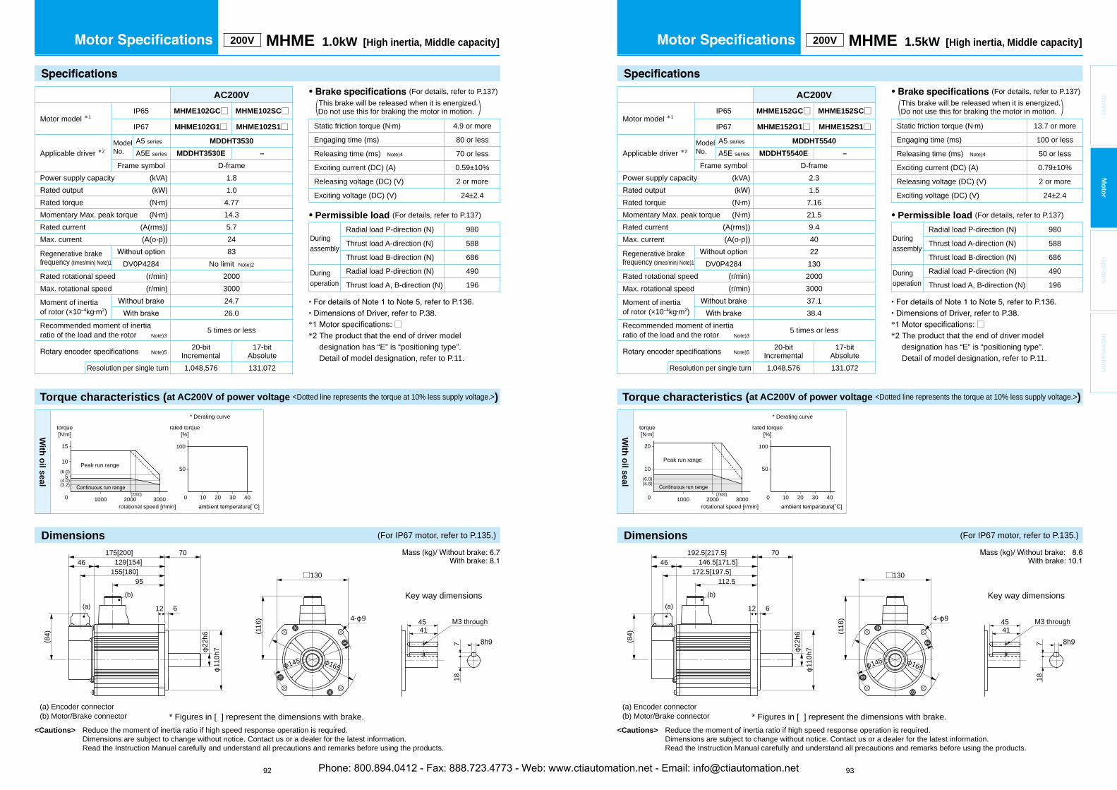
Torque characteristics (at AC200V of power voltage <Dotted line represents the torque at 10% less supply voltage.>)
<Cautions> Reduce the moment of inertia ratio if high speed response operation is required. Dimensions are subject to change without notice. Contact us or a dealer for the latest information. Read the Instruction Manual carefully and understand all precautions and remarks before using the products.
* □*2 The product that the end of driver model
designation has “E” is “positioning type”.Detail of model designation, refer to P.11.
Torque characteristics (at AC200V of power voltage <Dotted line represents the torque at 10% less supply voltage.>)
<Cautions> Reduce the moment of inertia ratio if high speed response operation is required. Dimensions are subject to change without notice. Contact us or a dealer for the latest information. Read the Instruction Manual carefully and understand all precautions and remarks before using the products.
92 93
* □*2 The product that the end of driver model
designation has “E” is “positioning type”.Detail of model designation, refer to P.11.
Driver
Mo
tor
Op
tion
sIn
form
ation
200V MHME 1.0kW [High inertia, Middle capacity]
• (For details, refer to P.137) This brake will be released when it is energized.(Do not use this for braking the motor in motion. )
Static friction torque (N m) 4.9 or more
Engaging time (ms) 80 or less
Releasing time (ms) Note)4 70 or less
Exciting current (DC) (A) 0.59±10%
Releasing voltage (DC) (V) 2 or more
Exciting voltage (DC) (V) 24±2.4
• Permissible load (For details, refer to P.137)
Duringassembly
Radial load P-direction (N) 980
Thrust load A-direction (N) 588
Thrust load B-direction (N) 686
Duringoperation
Radial load P-direction (N) 490
Thrust load A, B-direction (N) 196
AC200V
Motor model *1IP65 MHME102GC□ MHME102SC□
IP67 MHME102G1□ MHME102S1□
Applicable driver *2ModelNo.
A5 series MDDHT3530
A5E series MDDHT3530E –
Frame symbol D-framePower supply capacity (kVA) 1.8
1.0Rated torque (N m) 4.77Momentary Max. peak torque (N m) 14.3Rated current (A(rms)) 5.7Max. current (A(o-p)) 24
Regenerative brakefrequency (times/min) Note)1
83DV0P4284 No limit Note)2
Rated rotational speed (r/min) 2000Max. rotational speed (r/min) 3000
Moment of inertiaof rotor (×10 kg m2)
24.726.0
Recommended moment of inertia ratio of the load and the rotor Note)3
5 times or less
Note)520-bit
Incremental17-bit
AbsoluteResolution per single turn 1,048,576 131,072
With
oil seal
50
100
100 20 30 400 1000 2000 3000
15
10
5
(2200)
(3.2)(4.0)
(6.0)
torque[N m]
rotational speed [r/min]
Peak run range
rated torque[%]
* Derating curve
* Figures in [ ] represent the dimensions with brake.
M3 through
(116
) 4- 9
□130
165
4541
8h9718
145
(a) Encoder connector(b) Motor/Brake connector
Key way dimensions
46175[200] 70
12 6
110h
7
129[154]
22h6
155[180]95
(b)(a)
(84)
200V MHME 1.5kW [High inertia, Middle capacity]
• (For details, refer to P.137) This brake will be released when it is energized.(Do not use this for braking the motor in motion. )
Static friction torque (N m) 13.7 or more
Engaging time (ms) 100 or less
Releasing time (ms) Note)4 50 or less
Exciting current (DC) (A) 0.79±10%
Releasing voltage (DC) (V) 2 or more
Exciting voltage (DC) (V) 24±2.4
• Permissible load (For details, refer to P.137)
Duringassembly
Radial load P-direction (N) 980
Thrust load A-direction (N) 588
Thrust load B-direction (N) 686
Duringoperation
Radial load P-direction (N) 490
Thrust load A, B-direction (N) 196
AC200V
Motor model *1IP65 MHME152GC□ MHME152SC□
IP67 MHME152G1□ MHME152S1□
Applicable driver *2ModelNo.
A5 series MDDHT5540
A5E series MDDHT5540E –
Frame symbol D-framePower supply capacity (kVA) 2.3
1.5Rated torque (N m) 7.16Momentary Max. peak torque (N m) 21.5Rated current (A(rms)) 9.4Max. current (A(o-p)) 40
Regenerative brakefrequency (times/min) Note)1
22DV0P4284 130
Rated rotational speed (r/min) 2000Max. rotational speed (r/min) 3000
Moment of inertiaof rotor (×10 kg m2)
37.138.4
Recommended moment of inertia ratio of the load and the rotor Note)3
5 times or less
Note)520-bit
Incremental17-bit
AbsoluteResolution per single turn 1,048,576 131,072
With
oil seal
50
100
100 20 30 400 1000 2000 3000
20
10(6.0)(4.8)
(2300)
torque[N m]
rotational speed [r/min]
Peak run range
rated torque[%]
* Derating curve
* Figures in [ ] represent the dimensions with brake.
M3 through
(116
) 4- 9
□130
165
4541
8h9718
145
(a) Encoder connector(b) Motor/Brake connector
Key way dimensions
46192.5[217.5] 70
12 6
146.5[171.5]
22h6
172.5[197.5]112.5
(b)
110h
7
(a)
(84)
Dimensions (For IP67 motor, refer to P.135.) Dimensions (For IP67 motor, refer to P.135.)
Phone: 800.894.0412 - Fax: 888.723.4773 - Web: www.ctiautomation.net - Email: [email protected]

Torque characteristics (at AC200V of power voltage <Dotted line represents the torque at 10% less supply voltage.>)
<Cautions> Reduce the moment of inertia ratio if high speed response operation is required. Dimensions are subject to change without notice. Contact us or a dealer for the latest information. Read the Instruction Manual carefully and understand all precautions and remarks before using the products.
* □*2 The product that the end of driver model
designation has “E” is “positioning type”.Detail of model designation, refer to P.11.
Torque characteristics (at AC200V of power voltage <Dotted line represents the torque at 10% less supply voltage.>)
<Cautions> Reduce the moment of inertia ratio if high speed response operation is required. Dimensions are subject to change without notice. Contact us or a dealer for the latest information. Read the Instruction Manual carefully and understand all precautions and remarks before using the products.
94 95
* □*2 The product that the end of driver model
designation has “E” is “positioning type”.Detail of model designation, refer to P.11.
Driver
Mo
tor
Op
tion
sIn
form
ation
200V MHME 2.0kW [High inertia, Middle capacity]
• (For details, refer to P.137) This brake will be released when it is energized.(Do not use this for braking the motor in motion. )
Static friction torque (N m) 24.5 or more
Engaging time (ms) 80 or less
Releasing time (ms) Note)4 25 or less
Exciting current (DC) (A) 1.3±10%
Releasing voltage (DC) (V) 2 or more
Exciting voltage (DC) (V) 24±2.4
• Permissible load (For details, refer to P.137)
Duringassembly
Radial load P-direction (N) 1666
Thrust load A-direction (N) 784
Thrust load B-direction (N) 980
Duringoperation
Radial load P-direction (N) 784
Thrust load A, B-direction (N) 343
AC200V
Motor model *1IP65 MHME202GC□ MHME202SC□
IP67 MHME202G1□ MHME202S1□
Applicable driver *2ModelNo.
A5 series MEDHT7364
A5E series MEDHT7364E –
Frame symbol E-framePower supply capacity (kVA) 3.3
2.0Rated torque (N m) 9.55Momentary Max. peak torque (N m) 28.6Rated current (A(rms)) 11.1Max. current (A(o-p)) 47
Regenerative brakefrequency (times/min) Note)1
45DV0P4285 142
Rated rotational speed (r/min) 2000Max. rotational speed (r/min) 3000
Moment of inertiaof rotor (×10 kg m2)
57.859.6
Recommended moment of inertia ratio of the load and the rotor Note)3
5 times or less
Note)520-bit
Incremental17-bit
AbsoluteResolution per single turn 1,048,576 131,072
With
oil seal
50
100
100 20 30 400 1000 2000 3000
30
15
(2200)
(6.4)
torque[N m]
rotational speed [r/min]
Peak run range
rated torque[%]
* Derating curve
* Figures in [ ] represent the dimensions with brake.
M3 through
(140
)
4- 13.5
□176
5550
10h9830
200233
(a) Encoder connector(b) Motor/Brake connector
Key way dimensions
4680
18 3.2
133[158]179[204]
159[184]96
(b)
114.
3h7
35h6
(84)
(a)
200V MHME 3.0kW [High inertia, Middle capacity]
• (For details, refer to P.137) This brake will be released when it is energized.(Do not use this for braking the motor in motion. )
Static friction torque (N m) 24.5 or more
Engaging time (ms) 80 or less
Releasing time (ms) Note)4 25 or less
Exciting current (DC) (A) 1.3±10%
Releasing voltage (DC) (V) 2 or more
Exciting voltage (DC) (V) 24±2.4
• Permissible load (For details, refer to P.137)
Duringassembly
Radial load P-direction (N) 1666
Thrust load A-direction (N) 784
Thrust load B-direction (N) 980
Duringoperation
Radial load P-direction (N) 784
Thrust load A, B-direction (N) 343
AC200V
Motor model *1IP65 MHME302GC□ MHME302SC□
IP67 MHME302G1□ MHME302S1□
Applicable driver *2ModelNo.
A5 series MFDHTA390
A5E series MFDHTA390E –
Frame symbol F-framePower supply capacity (kVA) 4.5
3.0Rated torque (N m) 14.3Momentary Max. peak torque (N m) 43.0Rated current (A(rms)) 16.0Max. current (A(o-p)) 68
Regenerative brakefrequency (times/min) Note)1
19DV0P4285×2 142
Rated rotational speed (r/min) 2000Max. rotational speed (r/min) 3000
Moment of inertiaof rotor (×10 kg m2)
90.592.1
Recommended moment of inertia ratio of the load and the rotor Note)3
5 times or less
Note)520-bit
Incremental17-bit
AbsoluteResolution per single turn 1,048,576 131,072
With
oil seal
50
100
100 20 30 400 1000 2000 3000
50
25
(9.5)
(20)
(2400)
torque[N m]
rotational speed [r/min]
Peak run range
rated torque[%]
* Derating curve
* Figures in [ ] represent the dimensions with brake.
M3 through
(140
)
4- 13.5
□176
5550
10h9830
200233
(a) Encoder connector(b) Motor/Brake connector
Key way dimensions
4680
18 3.2
152[177]198[223]
178[203]115
(b)
114.
3h7
35h6
(84)
(a)
Dimensions (For IP67 motor, refer to P.135.) Dimensions (For IP67 motor, refer to P.135.)
Phone: 800.894.0412 - Fax: 888.723.4773 - Web: www.ctiautomation.net - Email: [email protected]

Torque characteristics (at AC200V of power voltage <Dotted line represents the torque at 10% less supply voltage.>)
<Cautions> Reduce the moment of inertia ratio if high speed response operation is required. Dimensions are subject to change without notice. Contact us or a dealer for the latest information. Read the Instruction Manual carefully and understand all precautions and remarks before using the products.
* □*2 The product that the end of driver model
designation has “E” is “positioning type”.Detail of model designation, refer to P.11.
Torque characteristics (at AC200V of power voltage <Dotted line represents the torque at 10% less supply voltage.>)
<Cautions> Reduce the moment of inertia ratio if high speed response operation is required. Dimensions are subject to change without notice. Contact us or a dealer for the latest information. Read the Instruction Manual carefully and understand all precautions and remarks before using the products.
96 97
* □*2 The product that the end of driver model
designation has “E” is “positioning type”.Detail of model designation, refer to P.11.
Driver
Mo
tor
Op
tion
sIn
form
ation
200V MHME 4.0kW [High inertia, Middle capacity]
• (For details, refer to P.137) This brake will be released when it is energized.(Do not use this for braking the motor in motion. )
Static friction torque (N m) 24.5 or more
Engaging time (ms) 80 or less
Releasing time (ms) Note)4 25 or less
Exciting current (DC) (A) 1.3±10%
Releasing voltage (DC) (V) 2 or more
Exciting voltage (DC) (V) 24±2.4
• Permissible load (For details, refer to P.137)
Duringassembly
Radial load P-direction (N) 1666
Thrust load A-direction (N) 784
Thrust load B-direction (N) 980
Duringoperation
Radial load P-direction (N) 784
Thrust load A, B-direction (N) 343
AC200V
Motor model *1IP65 MHME402GC□ MHME402SC□
IP67 MHME402G1□ MHME402S1□
Applicable driver *2ModelNo.
A5 series MFDHTB3A2
A5E series MFDHTB3A2E –
Frame symbol F-framePower supply capacity (kVA) 6.0
4.0Rated torque (N m) 19.1Momentary Max. peak torque (N m) 57.3Rated current (A(rms)) 21.0Max. current (A(o-p)) 89
Regenerative brakefrequency (times/min) Note)1
17DV0P4285×2 125
Rated rotational speed (r/min) 2000Max. rotational speed (r/min) 3000
Moment of inertiaof rotor (×10 kg m2)
112114
Recommended moment of inertia ratio of the load and the rotor Note)3
5 times or less
Note)520-bit
Incremental17-bit
AbsoluteResolution per single turn 1,048,576 131,072
With
oil seal
50
100
100 20 30 400 1000 2000 3000
50
25
(13)
(2100)(1900)
torque[N m]
rotational speed [r/min]
Peak run range
rated torque[%]
* Derating curve
* Figures in [ ] represent the dimensions with brake.
M3 through
(140
)
4- 13.5
□176
5550
10h9830
200233
(a) Encoder connector(b) Motor/Brake connector
Key way dimensions
4680
18 3.2
165.5[190.5]211.5[236.5]
191.5[216.5]128.5
(b)
114.
3h7
35h6
(84)
(a)
200V MHME 5.0kW [High inertia, Middle capacity]
• (For details, refer to P.137) This brake will be released when it is energized.(Do not use this for braking the motor in motion. )
Static friction torque (N m) 24.5 or more
Engaging time (ms) 80 or less
Releasing time (ms) Note)4 25 or less
Exciting current (DC) (A) 1.3±10%
Releasing voltage (DC) (V) 2 or more
Exciting voltage (DC) (V) 24±2.4
• Permissible load (For details, refer to P.137)
Duringassembly
Radial load P-direction (N) 1666
Thrust load A-direction (N) 784
Thrust load B-direction (N) 980
Duringoperation
Radial load P-direction (N) 784
Thrust load A, B-direction (N) 343
AC200V
Motor model *1IP65 MHME502GC□ MHME502SC□
IP67 MHME502G1□ MHME502S1□
Applicable driver *2ModelNo.
A5 series MFDHTB3A2
A5E series MFDHTB3A2E –
Frame symbol F-framePower supply capacity (kVA) 7.5
5.0Rated torque (N m) 23.9Momentary Max. peak torque (N m) 71.6Rated current (A(rms)) 25.9Max. current (A(o-p)) 110
Regenerative brakefrequency (times/min) Note)1
10DV0P4285×2 76
Rated rotational speed (r/min) 2000Max. rotational speed (r/min) 3000
Moment of inertiaof rotor (×10 kg m2)
162164
Recommended moment of inertia ratio of the load and the rotor Note)3
5 times or less
Note)520-bit
Incremental17-bit
AbsoluteResolution per single turn 1,048,576 131,072
With
oil seal
50
1009085
100 20 30 400 1000 2000 3000
70
35(20)
(3)(2100)(1900)
torque[N m]
rotational speed [r/min]
Peak run range with Brake
withoutBrake
rated torque[%]
* Derating curve
* Figures in [ ] represent the dimensions with brake.
M3 through
(140
)
4- 13.5
□176
5550
10h9830
200233
(a) Encoder connector(b) Motor/Brake connector
Key way dimensions
4680
18 3.2
194.5[219.5]240.5[265.5]
220.5[245.5]157.5
(b)
114.
3h7
35h6
(84)
(a)
Dimensions (For IP67 motor, refer to P.135.) Dimensions (For IP67 motor, refer to P.135.)
Phone: 800.894.0412 - Fax: 888.723.4773 - Web: www.ctiautomation.net - Email: [email protected]
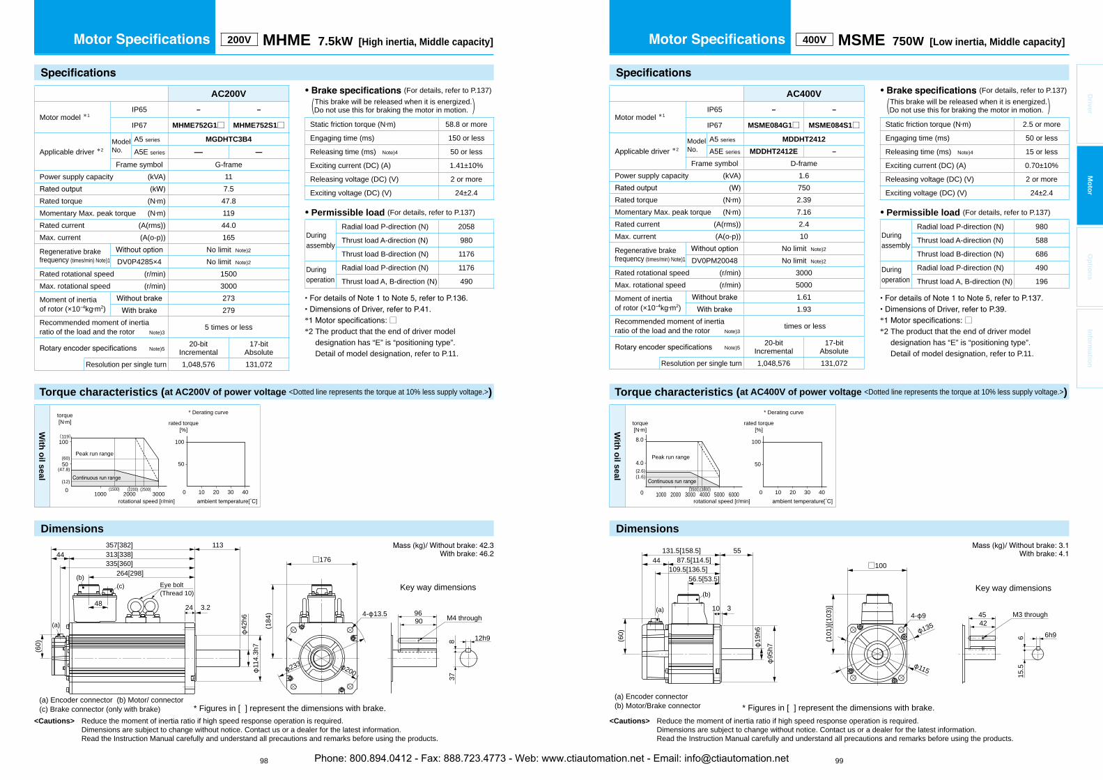
Dimensions
<Cautions> Reduce the moment of inertia ratio if high speed response operation is required. Dimensions are subject to change without notice. Contact us or a dealer for the latest information. Read the Instruction Manual carefully and understand all precautions and remarks before using the products.
Torque characteristics (at AC200V of power voltage <Dotted line represents the torque at 10% less supply voltage.>)
Dimensions
<Cautions> Reduce the moment of inertia ratio if high speed response operation is required. Dimensions are subject to change without notice. Contact us or a dealer for the latest information. Read the Instruction Manual carefully and understand all precautions and remarks before using the products.
98 99
* □*2 The product that the end of driver model
designation has “E” is “positioning type”.Detail of model designation, refer to P.11.
Driver
Mo
tor
Op
tion
sIn
form
ation
(a) Encoder connector (b) Motor/ connector(c) Brake connector (only with brake)
Key way dimensions
M4 through
(184
) 4- 13.5
□176
9690
12h98
200233
* Figures in [ ] represent the dimensions with brake.
(b)
(a)
(60)
44113
24 3.248
(c)
114.
3h7
42h6
357[382]313[338]335[360]
264[298]Eye bolt(Thread 10)
37
200V MHME 7.5kW [High inertia, Middle capacity]
AC200V
Motor model *1IP65 – –
IP67 MHME752G1□ MHME752S1□
Applicable driver *2ModelNo.
A5 series MGDHTC3B4
A5E series — —
Frame symbol G-framePower supply capacity (kVA) 11
7.5Rated torque (N m) 47.8Momentary Max. peak torque (N m) 119Rated current (A(rms)) 44.0Max. current (A(o-p)) 165
Regenerative brakefrequency (times/min) Note)1
No limit Note)2
DV0P4285×4 No limit Note)2
Rated rotational speed (r/min) 1500Max. rotational speed (r/min) 3000
Moment of inertiaof rotor (×10 kg m2)
273279
Recommended moment of inertia ratio of the load and the rotor Note)3
5 times or less
Note)520-bit
Incremental17-bit
AbsoluteResolution per single turn 1,048,576 131,072
With
oil seal
(47.8)
(12)
(60)50
100
100 20 30 400 1000 2000 3000(2500)(2200)
50
100(119)
(1500)
torque[N m]
rotational speed [r/min]
Peak run range
rated torque[%]
* Derating curve
• (For details, refer to P.137) This brake will be released when it is energized.(Do not use this for braking the motor in motion. )
Static friction torque (N m) 58.8 or more
Engaging time (ms) 150 or less
Releasing time (ms) Note)4 50 or less
Exciting current (DC) (A) 1.41±10%
Releasing voltage (DC) (V) 2 or more
Exciting voltage (DC) (V) 24±2.4
• Permissible load (For details, refer to P.137)
Duringassembly
Radial load P-direction (N) 2058
Thrust load A-direction (N) 980
Thrust load B-direction (N) 1176
Duringoperation
Radial load P-direction (N) 1176
Thrust load A, B-direction (N) 490
400V MSME 750W [Low inertia, Middle capacity]
AC400V
Motor model *1IP65 – –
IP67 MSME084G1□ MSME084S1□
Applicable driver *2ModelNo.
A5 series MDDHT2412
A5E series MDDHT2412E –
Frame symbol D-framePower supply capacity (kVA) 1.6
750Rated torque (N m) 2.39Momentary Max. peak torque (N m) 7.16Rated current (A(rms)) 2.4Max. current (A(o-p)) 10
Regenerative brakefrequency (times/min) Note)1
No limit Note)2
DV0PM20048 No limit Note)2
Rated rotational speed (r/min) 3000Max. rotational speed (r/min) 5000
Moment of inertiaof rotor (×10 kg m2)
1.611.93
Recommended moment of inertia ratio of the load and the rotor Note)3
times or less
Note)520-bit
Incremental17-bit
AbsoluteResolution per single turn 1,048,576 131,072
Torque characteristics (at AC400V of power voltage <Dotted line represents the torque at 10% less supply voltage.>)
• (For details, refer to P.137) This brake will be released when it is energized.(Do not use this for braking the motor in motion. )
Static friction torque (N m) 2.5 or more
Engaging time (ms) 50 or less
Releasing time (ms) Note)4 15 or less
Exciting current (DC) (A) 0.70±10%
Releasing voltage (DC) (V) 2 or more
Exciting voltage (DC) (V) 24±2.4
• Permissible load (For details, refer to P.137)
Duringassembly
Radial load P-direction (N) 980
Thrust load A-direction (N) 588
Thrust load B-direction (N) 686
Duringoperation
Radial load P-direction (N) 490
Thrust load A, B-direction (N) 196
With
oil seal
torque[N m]
rotational speed [r/min]
50
100
100 20 30 40
Peak run range
8.0
(2.6)(1.6)
(3500)(3800)
4.0
0 1000 2000 3000 4000 5000 6000
rated torque[%]
* Derating curve
* Figures in [ ] represent the dimensions with brake.
115
1354542
6h9615
.5
(101
)[(10
3)]
□100
131.5[158.5]87.5[114.5]44
55
10 3(6
0)
19h6
109.5[136.5]56.5[53.5]
95h7
4- 9 M3 through(a)
(b)
(a) Encoder connector(b) Motor/Brake connector
Key way dimensions
* □*2 The product that the end of driver model
designation has “E” is “positioning type”.Detail of model designation, refer to P.11.
Phone: 800.894.0412 - Fax: 888.723.4773 - Web: www.ctiautomation.net - Email: [email protected]

<Cautions> Reduce the moment of inertia ratio if high speed response operation is required. Dimensions are subject to change without notice. Contact us or a dealer for the latest information. Read the Instruction Manual carefully and understand all precautions and remarks before using the products.
<Cautions> Reduce the moment of inertia ratio if high speed response operation is required. Dimensions are subject to change without notice. Contact us or a dealer for the latest information. Read the Instruction Manual carefully and understand all precautions and remarks before using the products.
100 101
Driver
Mo
tor
Op
tion
sIn
form
ation
400V MSME 1.0kW [Low inertia, Middle capacity]
AC400V
Motor model *1IP65 MSME104GC□ MSME104SC□
IP67 MSME104G1□ MSME104S1□
Applicable driver *2ModelNo.
A5 series MDDHT3420
A5E series MDDHT3420E –
Frame symbol D-framePower supply capacity (kVA) 1.8
1.0Rated torque (N m) 3.18Momentary Max. peak torque (N m) 9.55Rated current (A(rms)) 3.3Max. current (A(o-p)) 14
Regenerative brakefrequency (times/min) Note)1
No limit Note)2
DV0PM20048 No limit Note)2
Rated rotational speed (r/min) 3000Max. rotational speed (r/min) 5000
Moment of inertiaof rotor (×10 kg m2)
2.032.35
Recommended moment of inertia ratio of the load and the rotor Note)3
15 times or less
Note)520-bit
Incremental17-bit
AbsoluteResolution per single turn 1,048,576 131,072
• (For details, refer to P.137) This brake will be released when it is energized.(Do not use this for braking the motor in motion. )
Static friction torque (N m) 7.8 or more
Engaging time (ms) 50 or less
Releasing time (ms) Note)4 15 or less
Exciting current (DC) (A) 0.81±10%
Releasing voltage (DC) (V) 2 or more
Exciting voltage (DC) (V) 24±2.4
• Permissible load (For details, refer to P.137)
Duringassembly
Radial load P-direction (N) 980
Thrust load A-direction (N) 588
Thrust load B-direction (N) 686
Duringoperation
Radial load P-direction (N) 490
Thrust load A, B-direction (N) 196
With
oil seal
50
100
100 20 30 40
10
5
0 1000 2000 3000 4000 5000
(4.0)
(1.9)
(6.0)
(4200)(3800)
torque[N m]
rotational speed [r/min]
Peak run range
rated torque[%]
* Derating curve
* Figures in [ ] represent the dimensions with brake.
115
1354542
6h9615
.5
(101
)[(10
3)]
□100
4- 9 M3 through
(a) Encoder connector(b) Motor/Brake connector
Key way dimensions
143[170]97[124]46
55
10 3
19h6
123[150]66
95h7
(b)
(84)
(a)
Torque characteristics (at AC400V of power voltage <Dotted line represents the torque at 10% less supply voltage.>)
400V MSME 1.5kW [Low inertia, Middle capacity]
AC400V
Motor model *1IP65 MSME154GC□ MSME154SC□
IP67 MSME154G1□ MSME154S1□
Applicable driver *2ModelNo.
A5 series MDDHT3420
A5E series MDDHT3420E –
Frame symbol D-framePower supply capacity (kVA) 2.3
1.5Rated torque (N m) 4.77Momentary Max. peak torque (N m) 14.3Rated current (A(rms)) 4.2Max. current (A(o-p)) 18
Regenerative brakefrequency (times/min) Note)1
No limit Note)2
DV0PM20048 No limit Note)2
Rated rotational speed (r/min) 3000Max. rotational speed (r/min) 5000
Moment of inertiaof rotor (×10 kg m2)
2.843.17
Recommended moment of inertia ratio of the load and the rotor Note)3
15 times or less
Note)520-bit
Incremental17-bit
AbsoluteResolution per single turn 1,048,576 131,072
• (For details, refer to P.137) This brake will be released when it is energized.(Do not use this for braking the motor in motion. )
Static friction torque (N m) 7.8 or more
Engaging time (ms) 50 or less
Releasing time (ms) Note)4 15 or less
Exciting current (DC) (A) 0.81±10%
Releasing voltage (DC) (V) 2 or more
Exciting voltage (DC) (V) 24±2.4
• Permissible load (For details, refer to P.137)
Duringassembly
Radial load P-direction (N) 980
Thrust load A-direction (N) 588
Thrust load B-direction (N) 686
Duringoperation
Radial load P-direction (N) 490
Thrust load A, B-direction (N) 196
Torque characteristics (at AC400V of power voltage <Dotted line represents the torque at 10% less supply voltage.>)
With
oil seal
50
100
100 20 30 40
85
(3600)(3200)0 1000 2000 3000 4000 5000
15
7.5
(4.0)
torque[N m]
rotational speed [r/min]
Peak run rangewith Brake
withoutBrake
rated torque[%]
* Derating curve
* Figures in [ ] represent the dimensions with brake.
4542
6h9615
.5
M3 through
(a) Encoder connector(b) Motor/Brake connector
Key way dimensions
115
135
(101
)[(10
3)]
□100
4- 9(8
4)
(a)
161.5[188.5]115.5[142.5]46
55
10 3
19h6
141.5[168.5]84.5
(b)
95h7
Dimensions (For IP67 motor, refer to P.132.) Dimensions (For IP67 motor, refer to P.132.)
* □*2 The product that the end of driver model
designation has “E” is “positioning type”.Detail of model designation, refer to P.11.
* □*2 The product that the end of driver model
designation has “E” is “positioning type”.Detail of model designation, refer to P.11.
Phone: 800.894.0412 - Fax: 888.723.4773 - Web: www.ctiautomation.net - Email: [email protected]

<Cautions> Reduce the moment of inertia ratio if high speed response operation is required. Dimensions are subject to change without notice. Contact us or a dealer for the latest information. Read the Instruction Manual carefully and understand all precautions and remarks before using the products.
<Cautions> Reduce the moment of inertia ratio if high speed response operation is required. Dimensions are subject to change without notice. Contact us or a dealer for the latest information. Read the Instruction Manual carefully and understand all precautions and remarks before using the products.
102 103
Driver
Mo
tor
Op
tion
sIn
form
ation
400V MSME 2.0kW [Low inertia, Middle capacity]
AC400V
Motor model *1IP65 MSME204GC□ MSME204SC□
IP67 MSME204G1□ MSME204S1□
Applicable driver *2ModelNo.
A5 series MEDHT4430
A5E series MEDHT4430E –
Frame symbol E-framePower supply capacity (kVA) 3.3
2.0Rated torque (N m) 6.37Momentary Max. peak torque (N m) 19.1Rated current (A(rms)) 5.7Max. current (A(o-p)) 24
Regenerative brakefrequency (times/min) Note)1
No limit Note)2
DV0PM20049 No limit Note)2
Rated rotational speed (r/min) 3000Max. rotational speed (r/min) 5000
Moment of inertiaof rotor (×10 kg m2)
3.684.01
Recommended moment of inertia ratio of the load and the rotor Note)3
15 times or less
Note)520-bit
Incremental17-bit
AbsoluteResolution per single turn 1,048,576 131,072
• (For details, refer to P.137) This brake will be released when it is energized.(Do not use this for braking the motor in motion. )
Static friction torque (N m) 7.8 or more
Engaging time (ms) 50 or less
Releasing time (ms) Note)4 15 or less
Exciting current (DC) (A) 0.81±10%
Releasing voltage (DC) (V) 2 or more
Exciting voltage (DC) (V) 24±2.4
• Permissible load (For details, refer to P.137)
Duringassembly
Radial load P-direction (N) 980
Thrust load A-direction (N) 588
Thrust load B-direction (N) 686
Duringoperation
Radial load P-direction (N) 490
Thrust load A, B-direction (N) 196
Torque characteristics (at AC400V of power voltage <Dotted line represents the torque at 10% less supply voltage.>)
With
oil seal
50
100
100 20 30 40
8570
0 1000 2000 3000 4000 5000
20
10(7.0)
(2.0)(3700)(3300)
torque[N m]
rotational speed [r/min]
Peak run range with Brake
withoutBrake
rated torque[%]
* Derating curve
* Figures in [ ] represent the dimensions with brake.
4542
6h9
15.5
M3 through
6
(a) Encoder connector(b) Motor/Brake connector
Key way dimensions
115
135
(101
)[(10
3)]
□100
4- 9
180.5[207.5]134.5[161.5]46
55
10 3
19h6
160.5[187.5]103.5
(b)
95h7
(84)
(a)
AC400V
Motor model *1IP65 MSME304GC□ MSME304SC□
IP67 MSME304G1□ MSME304S1□
Applicable driver *2ModelNo.
A5 series MFDHT5440
A5E series MFDHT5440E –
Frame symbol F-framePower supply capacity (kVA) 4.5
3.0Rated torque (N m) 9.55Momentary Max. peak torque (N m) 28.6Rated current (A(rms)) 9.2Max. current (A(o-p)) 39
Regenerative brakefrequency (times/min) Note)1
No limit Note)2
DV0PM20049×2 No limit Note)2
Rated rotational speed (r/min) 3000Max. rotational speed (r/min) 5000
Moment of inertiaof rotor (×10 kg m2)
6.507.85
Recommended moment of inertia ratio of the load and the rotor Note)3
15 times or less
Note)520-bit
Incremental17-bit
AbsoluteResolution per single turn 1,048,576 131,072
• (For details, refer to P.137) This brake will be released when it is energized.(Do not use this for braking the motor in motion. )
Static friction torque (N m) 11.8 or more
Engaging time (ms) 80 or less
Releasing time (ms) Note)4 15 or less
Exciting current (DC) (A) 0.81±10%
Releasing voltage (DC) (V) 2 or more
Exciting voltage (DC) (V) 24±2.4
• Permissible load (For details, refer to P.137)
Duringassembly
Radial load P-direction (N) 980
Thrust load A-direction (N) 588
Thrust load B-direction (N) 686
Duringoperation
Radial load P-direction (N) 490
Thrust load A, B-direction (N) 196
400V MSME 3.0kW [Low inertia, Middle capacity]
Torque characteristics (at AC400V of power voltage <Dotted line represents the torque at 10% less supply voltage.>)
With
oil seal
50
100
100 20 30 40
9085
0 1000 2000 3000 4000 5000
30
15(12)
(8.0)(5.7)
(3400)(3100)
torque[N m]
rotational speed [r/min]
Peak run range with Brake
withoutBrake
rated torque[%]
* Derating curve
* Figures in [ ] represent the dimensions with brake.
M3 through
(113
) 4- 9
□120
145162
4541
8h9718
(a) Encoder connector(b) Motor/Brake connector
Key way dimensions
46192[217] 55
12 3
110h
7
146[171]
22h6
172[197]112
(84)
(a)(b)
Dimensions (For IP67 motor, refer to P.132.)Dimensions (For IP67 motor, refer to P.132.)
* □*2 The product that the end of driver model
designation has “E” is “positioning type”.Detail of model designation, refer to P.11.
* □*2 The product that the end of driver model
designation has “E” is “positioning type”.Detail of model designation, refer to P.11.
Phone: 800.894.0412 - Fax: 888.723.4773 - Web: www.ctiautomation.net - Email: [email protected]

<Cautions> Reduce the moment of inertia ratio if high speed response operation is required. Dimensions are subject to change without notice. Contact us or a dealer for the latest information. Read the Instruction Manual carefully and understand all precautions and remarks before using the products.
<Cautions> Reduce the moment of inertia ratio if high speed response operation is required. Dimensions are subject to change without notice. Contact us or a dealer for the latest information. Read the Instruction Manual carefully and understand all precautions and remarks before using the products.
104 105
Driver
Mo
tor
Op
tion
sIn
form
ation
400V MSME 4.0kW [Low inertia, Middle capacity]
AC400V
Motor model *1IP65 MSME404GC□ MSME404SC□
IP67 MSME404G1□ MSME404S1□
Applicable driver *2ModelNo.
A5 series MFDHTA464
A5E series MFDHTA464E –
Frame symbol F-framePower supply capacity (kVA) 6.8
4.0Rated torque (N m) 12.7Momentary Max. peak torque (N m) 38.2Rated current (A(rms)) 9.9Max. current (A(o-p)) 42
Regenerative brakefrequency (times/min) Note)1
No limit Note)2
DV0PM20049×2 No limit Note)2
Rated rotational speed (r/min) 3000Max. rotational speed (r/min) 4500
Moment of inertiaof rotor (×10 kg m2)
12.914.2
Recommended moment of inertia ratio of the load and the rotor Note)3
15 times or less
Note)520-bit
Incremental17-bit
AbsoluteResolution per single turn 1,048,576 131,072
• (For details, refer to P.137) This brake will be released when it is energized.(Do not use this for braking the motor in motion. )
Static friction torque (N m) 16.2 or more
Engaging time (ms) 110 or less
Releasing time (ms) Note)4 50 or less
Exciting current (DC) (A) 0.90±10%
Releasing voltage (DC) (V) 2 or more
Exciting voltage (DC) (V) 24±2.4
• Permissible load (For details, refer to P.137)
Duringassembly
Radial load P-direction (N) 980
Thrust load A-direction (N) 588
Thrust load B-direction (N) 686
Duringoperation
Radial load P-direction (N) 784
Thrust load A, B-direction (N) 343
Torque characteristics (at AC400V of power voltage <Dotted line represents the torque at 10% less supply voltage.>)
With
oil seal
50
100
100 20 30 40
9085
0 1000 2000 3000 4000 5000
40
20
(10)
(3100)(2800)
torque[N m]
rotational speed [r/min]
Peak run rangewith Brake
withoutBrake
rated torque[%]
* Derating curve
* Figures in [ ] represent the dimensions with brake.
M3 through
(118
) 4- 9
□130
145 165
5551
8h9720
(a) Encoder connector(b) Motor/Brake connector
Key way dimensions
46210[235] 65
12 6
110h
7
164[189]
24h6
190[215]127
(b)
(84)
(a)
400V MSME 5.0kW [Low inertia, Middle capacity]
AC400V
Motor model *1IP65 MSME504GC□ MSME504SC□
IP67 MSME504G1□ MSME504S1□
Applicable driver *2ModelNo.
A5 series MFDHTA464
A5E series MFDHTA464E –
Frame symbol F-framePower supply capacity (kVA) 7.5
5.0Rated torque (N m) 15.9Momentary Max. peak torque (N m) 47.7Rated current (A(rms)) 12.0Max. current (A(o-p)) 51
Regenerative brakefrequency (times/min) Note)1
357DV0PM20049×2 No limit Note)2
Rated rotational speed (r/min) 3000Max. rotational speed (r/min) 4500
Moment of inertiaof rotor (×10 kg m2)
17.418.6
Recommended moment of inertia ratio of the load and the rotor Note)3
15 times or less
Note)520-bit
Incremental17-bit
AbsoluteResolution per single turn 1,048,576 131,072
• (For details, refer to P.137) This brake will be released when it is energized.(Do not use this for braking the motor in motion. )
Static friction torque (N m) 16.2 or more
Engaging time (ms) 110 or less
Releasing time (ms) Note)4 50 or less
Exciting current (DC) (A) 0.90±10%
Releasing voltage (DC) (V) 2 or more
Exciting voltage (DC) (V) 24±2.4
• Permissible load (For details, refer to P.137)
Duringassembly
Radial load P-direction (N) 980
Thrust load A-direction (N) 588
Thrust load B-direction (N) 686
Duringoperation
Radial load P-direction (N) 784
Thrust load A, B-direction (N) 343
Torque characteristics (at AC400V of power voltage <Dotted line represents the torque at 10% less supply voltage.>)
With
oil seal
50
100
100 20 30 40
70
0 1000 2000 3000 4000 5000
50
25
(15)
(3200)(2800)
torque[N m]
rotational speed [r/min]
Peak run range
rated torque[%]
* Derating curve
* Figures in [ ] represent the dimensions with brake.
M3 through
(118
) 4- 9
□130
145 165
5551
8h9720
(a) Encoder connector(b) Motor/Brake connector
Key way dimensions
46245[270] 65
12 6
110h
7
199[224]
24h6
225[250]162
(b)
(84)
(a)
Dimensions (For IP67 motor, refer to P.132.)Dimensions (For IP67 motor, refer to P.132.)
* □*2 The product that the end of driver model
designation has “E” is “positioning type”.Detail of model designation, refer to P.11.
* □*2 The product that the end of driver model
designation has “E” is “positioning type”.Detail of model designation, refer to P.11.
Phone: 800.894.0412 - Fax: 888.723.4773 - Web: www.ctiautomation.net - Email: [email protected]

Dimensions
<Cautions> Reduce the moment of inertia ratio if high speed response operation is required. Dimensions are subject to change without notice. Contact us or a dealer for the latest information. Read the Instruction Manual carefully and understand all precautions and remarks before using the products.
106 107
Driver
Mo
tor
Op
tion
sIn
form
ation
* Figures in [ ] represent the dimensions with brake.
115
1354542
6h9615
.5
(101
)[(10
3)]
□100
141[168]97[124]44
55
10 3(6
0)
19h6
119[146]66[63]
95h7
4- 9 M3 through(a)
(b)
(a) Encoder connector(b) Motor/Brake connector
Key way dimensions
* Figures in [ ] represent the dimensions with brake.
115
1354542
6h9615
.5
(101
)[(10
3)]
□100
131.5[158.5]87.5[114.5]44
55
10 3
(60)
19h6
109.5[136.5]56.5[53.5]
95h7
4- 9 M3 through(a)
(b)
(a) Encoder connector(b) Motor/Brake connector
Key way dimensions
400V MDME 400W [Middle inertia, Middle capacity] 400V MDME 600W [Middle inertia, Middle capacity]
• (For details, refer to P.137) This brake will be released when it is energized.(Do not use this for braking the motor in motion. )
Static friction torque (N m) 2.5 or more
Engaging time (ms) 50 or less
Releasing time (ms) Note)4 15 or less
Exciting current (DC) (A) 0.70±10%
Releasing voltage (DC) (V) 2 or more
Exciting voltage (DC) (V) 24±2.4
• Permissible load (For details, refer to P.137)
Duringassembly
Radial load P-direction (N) 980
Thrust load A-direction (N) 588
Thrust load B-direction (N) 686
Duringoperation
Radial load P-direction (N) 490
Thrust load A, B-direction (N) 196
Torque characteristics (at AC400V of power voltage <Dotted line represents the torque at 10% less supply voltage.>)Torque characteristics (at AC400V of power voltage <Dotted line represents the torque at 10% less supply voltage.>)
With
oil seal
torque[N m]
rotational speed [r/min]
50
100
100 20 30 40
Peak run range
0 1000 2000 3000
6
4
2
(2400) (2700)
(3.5)
(1.3)
rated torque[%]
* Derating curve
With
oil seal
torque[N m]
rotational speed [r/min]
50
100
100 20 30 400 1000 2000 3000
10
5
(2100)(2400)
(4.5)
(1.9)
Peak run range
rated torque[%]
* Derating curve
AC400V
Motor model *1IP65 – –
IP67 MDME044G1□ MDME044S1□
Applicable driver *2ModelNo.
A5 series MDDHT2407
A5E series MDDHT2407E –
Frame symbol D-framePower supply capacity (kVA) 0.9
400Rated torque (N m) 1.91Momentary Max. peak torque (N m) 5.73Rated current (A(rms)) 1.2Max. current (A(o-p)) 4.9
Regenerative brakefrequency (times/min) Note)1
No limit Note)2
DV0PM20048 No limit Note)2
Rated rotational speed (r/min) 2000Max. rotational speed (r/min) 3000
Moment of inertiaof rotor (×10 kg m2)
1.611.9
Recommended moment of inertia ratio of the load and the rotor Note)3
times or less
Note)520-bit
Incremental17-bit
AbsoluteResolution per single turn 1,048,576 131,072
AC400V
Motor model *1IP65 – –
IP67 MDME064G1□ MDME064S1□
Applicable driver *2ModelNo.
A5 series MDDHT2407
A5E series MDDHT2407E –
Frame symbol D-framePower supply capacity (kVA) 1.2
600Rated torque (N m) 2.86Momentary Max. peak torque (N m) 8.59Rated current (A(rms)) 1.5Max. current (A(o-p)) 6.5
Regenerative brakefrequency (times/min) Note)1
No limit Note)2
DV0PM20048 No limit Note)2
Rated rotational speed (r/min) 2000Max. rotational speed (r/min) 3000
Moment of inertiaof rotor (×10 kg m2)
2.032.35
Recommended moment of inertia ratio of the load and the rotor Note)3
times or less
Note)520-bit
Incremental17-bit
AbsoluteResolution per single turn 1,048,576 131,072
* □*2 The product that the end of driver model
designation has “E” is “positioning type”.Detail of model designation, refer to P.11.
* □*2 The product that the end of driver model
designation has “E” is “positioning type”.Detail of model designation, refer to P.11.
Phone: 800.894.0412 - Fax: 888.723.4773 - Web: www.ctiautomation.net - Email: [email protected]

<Cautions> Reduce the moment of inertia ratio if high speed response operation is required. Dimensions are subject to change without notice. Contact us or a dealer for the latest information. Read the Instruction Manual carefully and understand all precautions and remarks before using the products.
<Cautions> Reduce the moment of inertia ratio if high speed response operation is required. Dimensions are subject to change without notice. Contact us or a dealer for the latest information. Read the Instruction Manual carefully and understand all precautions and remarks before using the products.
108 109
Driver
Mo
tor
Op
tion
sIn
form
ation
400V MDME 1.0kW [Middle inertia, Middle capacity]
AC400V
Motor model *1IP65 MDME104GC□ MDME104SC□
IP67 MDME104G1□ MDME104S1□
Applicable driver *2ModelNo.
A5 series MDDHT2412
A5E series MDDHT2412E –
Frame symbol D-framePower supply capacity (kVA) 1.8
1.0Rated torque (N m) 4.77Momentary Max. peak torque (N m) 14.3Rated current (A(rms)) 2.8Max. current (A(o-p)) 12
Regenerative brakefrequency (times/min) Note)1
No limit Note)2
DV0PM20048 No limit Note)2
Rated rotational speed (r/min) 2000Max. rotational speed (r/min) 3000
Moment of inertiaof rotor (×10 kg m2)
4.605.90
Recommended moment of inertia ratio of the load and the rotor Note)3
10 times or less
Note)520-bit
Incremental17-bit
AbsoluteResolution per single turn 1,048,576 131,072
• (For details, refer to P.137) This brake will be released when it is energized.(Do not use this for braking the motor in motion. )
Static friction torque (N m) 4.9 or more
Engaging time (ms) 80 or less
Releasing time (ms) Note)4 70 or less
Exciting current (DC) (A) 0.59±10%
Releasing voltage (DC) (V) 2 or more
Exciting voltage (DC) (V) 24±2.4
• Permissible load (For details, refer to P.137)
Duringassembly
Radial load P-direction (N) 980
Thrust load A-direction (N) 588
Thrust load B-direction (N) 686
Duringoperation
Radial load P-direction (N) 490
Thrust load A, B-direction (N) 196
Torque characteristics (at AC400V of power voltage <Dotted line represents the torque at 10% less supply voltage.>)
With
oil seal
50
100
100 20 30 400 1000 2000 3000
15
10
5
(2200)
(6.0)
(4.0)(3.2)
torque[N m]
rotational speed [r/min]
Peak run range
rated torque[%]
* Derating curve
* Figures in [ ] represent the dimensions with brake.
M3 through
Key way dimensions
(116
) 4- 9
□130
165
4541
8h9718
145
(a) Encoder connector(b) Motor/Brake connector
46140[165] 55
12 6
94[119]
22h6
120[145]60
(b)
110h
7
(a)
(84)
400V MDME 1.5kW [Middle inertia, Middle capacity]
AC400V
Motor model *1IP65 MDME154GC□ MDME154SC□
IP67 MDME154G1□ MDME154S1□
Applicable driver *2ModelNo.
A5 series MDDHT3420
A5E series MDDHT3420E –
Frame symbol D-framePower supply capacity (kVA) 2.3
1.5Rated torque (N m) 7.16Momentary Max. peak torque (N m) 21.5Rated current (A(rms)) 4.7Max. current (A(o-p)) 20
Regenerative brakefrequency (times/min) Note)1
No limit Note)2
DV0PM20048 No limit Note)2
Rated rotational speed (r/min) 2000Max. rotational speed (r/min) 3000
Moment of inertiaof rotor (×10 kg m2)
6.707.99
Recommended moment of inertia ratio of the load and the rotor Note)3
10 times or less
Note)520-bit
Incremental17-bit
AbsoluteResolution per single turn 1,048,576 131,072
• (For details, refer to P.137) This brake will be released when it is energized.(Do not use this for braking the motor in motion. )
Static friction torque (N m) 13.7 or more
Engaging time (ms) 100 or less
Releasing time (ms) Note)4 50 or less
Exciting current (DC) (A) 0.79±10%
Releasing voltage (DC) (V) 2 or more
Exciting voltage (DC) (V) 24±2.4
• Permissible load (For details, refer to P.137)
Duringassembly
Radial load P-direction (N) 980
Thrust load A-direction (N) 588
Thrust load B-direction (N) 686
Duringoperation
Radial load P-direction (N) 490
Thrust load A, B-direction (N) 196
Torque characteristics (at AC400V of power voltage <Dotted line represents the torque at 10% less supply voltage.>)
With
oil seal
50
100
100 20 30 40(2300)0 1000 2000 3000
20
10(6.0)(4.8)
torque[N m]
rotational speed [r/min]
Peak run range
rated torque[%]
* Derating curve
* Figures in [ ] represent the dimensions with brake.
M3 through4541
8h9718
(a) Encoder connector(b) Motor/Brake connector
Key way dimensions
(116
) 4- 9
□130
165145
(a)
(84)
46157.5[182.5] 55
12 6
111.5[136.5]
22h6
137.5[162.5]77.5
(b)
110h
7
Dimensions (For IP67 motor, refer to P.133.) Dimensions (For IP67 motor, refer to P.133.)
* □*2 The product that the end of driver model
designation has “E” is “positioning type”.Detail of model designation, refer to P.11.
* □*2 The product that the end of driver model
designation has “E” is “positioning type”.Detail of model designation, refer to P.11.
Phone: 800.894.0412 - Fax: 888.723.4773 - Web: www.ctiautomation.net - Email: [email protected]
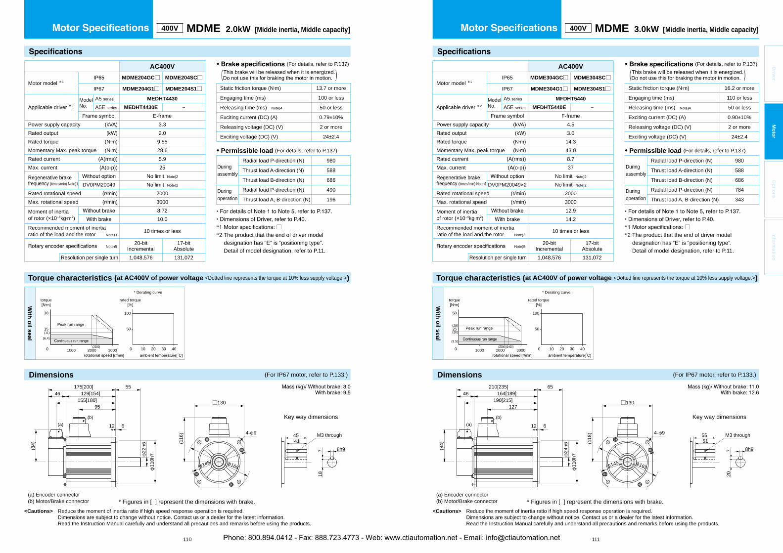
<Cautions> Reduce the moment of inertia ratio if high speed response operation is required. Dimensions are subject to change without notice. Contact us or a dealer for the latest information. Read the Instruction Manual carefully and understand all precautions and remarks before using the products.
<Cautions> Reduce the moment of inertia ratio if high speed response operation is required. Dimensions are subject to change without notice. Contact us or a dealer for the latest information. Read the Instruction Manual carefully and understand all precautions and remarks before using the products.
110 111
Driver
Mo
tor
Op
tion
sIn
form
ation
400V MDME 2.0kW [Middle inertia, Middle capacity]
AC400V
Motor model *1IP65 MDME204GC□ MDME204SC□
IP67 MDME204G1□ MDME204S1□
Applicable driver *2ModelNo.
A5 series MEDHT4430
A5E series MEDHT4430E –
Frame symbol E-framePower supply capacity (kVA) 3.3
2.0Rated torque (N m) 9.55Momentary Max. peak torque (N m) 28.6Rated current (A(rms)) 5.9Max. current (A(o-p)) 25
Regenerative brakefrequency (times/min) Note)1
No limit Note)2
DV0PM20049 No limit Note)2
Rated rotational speed (r/min) 2000Max. rotational speed (r/min) 3000
Moment of inertiaof rotor (×10 kg m2)
8.7210.0
Recommended moment of inertia ratio of the load and the rotor Note)3
10 times or less
Note)520-bit
Incremental17-bit
AbsoluteResolution per single turn 1,048,576 131,072
• (For details, refer to P.137) This brake will be released when it is energized.(Do not use this for braking the motor in motion. )
Static friction torque (N m) 13.7 or more
Engaging time (ms) 100 or less
Releasing time (ms) Note)4 50 or less
Exciting current (DC) (A) 0.79±10%
Releasing voltage (DC) (V) 2 or more
Exciting voltage (DC) (V) 24±2.4
• Permissible load (For details, refer to P.137)
Duringassembly
Radial load P-direction (N) 980
Thrust load A-direction (N) 588
Thrust load B-direction (N) 686
Duringoperation
Radial load P-direction (N) 490
Thrust load A, B-direction (N) 196
Torque characteristics (at AC400V of power voltage <Dotted line represents the torque at 10% less supply voltage.>)
With
oil seal
50
100
100 20 30 400 1000 2000 3000
30
15
(2200)
(11)(6.4)
torque[N m]
rotational speed [r/min]
Peak run range
rated torque[%]
* Derating curve
* Figures in [ ] represent the dimensions with brake.
M3 through4541
8h9718
(a) Encoder connector(b) Motor/Brake connector
Key way dimensions
(116
) 4- 9
□130
165145
46175[200] 55
12 6
129[154]
22h6
155[180]95
(b)
110h
7
(a)
(84)
400V MDME 3.0kW [Middle inertia, Middle capacity]
AC400V
Motor model *1IP65 MDME304GC□ MDME304SC□
IP67 MDME304G1□ MDME304S1□
Applicable driver *2ModelNo.
A5 series MFDHT5440
A5E series MFDHT5440E –
Frame symbol F-framePower supply capacity (kVA) 4.5
3.0Rated torque (N m) 14.3Momentary Max. peak torque (N m) 43.0Rated current (A(rms)) 8.7Max. current (A(o-p)) 37
Regenerative brakefrequency (times/min) Note)1
No limit Note)2
DV0PM20049×2 No limit Note)2
Rated rotational speed (r/min) 2000Max. rotational speed (r/min) 3000
Moment of inertiaof rotor (×10 kg m2)
12.914.2
Recommended moment of inertia ratio of the load and the rotor Note)3
10 times or less
Note)520-bit
Incremental17-bit
AbsoluteResolution per single turn 1,048,576 131,072
• (For details, refer to P.137) This brake will be released when it is energized.(Do not use this for braking the motor in motion. )
Static friction torque (N m) 16.2 or more
Engaging time (ms) 110 or less
Releasing time (ms) Note)4 50 or less
Exciting current (DC) (A) 0.90±10%
Releasing voltage (DC) (V) 2 or more
Exciting voltage (DC) (V) 24±2.4
• Permissible load (For details, refer to P.137)
Duringassembly
Radial load P-direction (N) 980
Thrust load A-direction (N) 588
Thrust load B-direction (N) 686
Duringoperation
Radial load P-direction (N) 784
Thrust load A, B-direction (N) 343
Torque characteristics (at AC400V of power voltage <Dotted line represents the torque at 10% less supply voltage.>)
With
oil seal
50
100
100 20 30 400 1000 2000 3000
50
25(28)
(20)
(9.5)(2200)(2400)
torque[N m]
rotational speed [r/min]
Peak run range
rated torque[%]
* Derating curve
* Figures in [ ] represent the dimensions with brake.
M3 through5551
8h9720
(a) Encoder connector(b) Motor/Brake connector
Key way dimensions
(118
) 4- 9
□130
165145
46210[235] 65
12 6
164[189]
24h6
190[215]127
(b)
110h
7
(a)
(84)
Dimensions (For IP67 motor, refer to P.133.) Dimensions (For IP67 motor, refer to P.133.)
* □*2 The product that the end of driver model
designation has “E” is “positioning type”.Detail of model designation, refer to P.11.
* □*2 The product that the end of driver model
designation has “E” is “positioning type”.Detail of model designation, refer to P.11.
Phone: 800.894.0412 - Fax: 888.723.4773 - Web: www.ctiautomation.net - Email: [email protected]
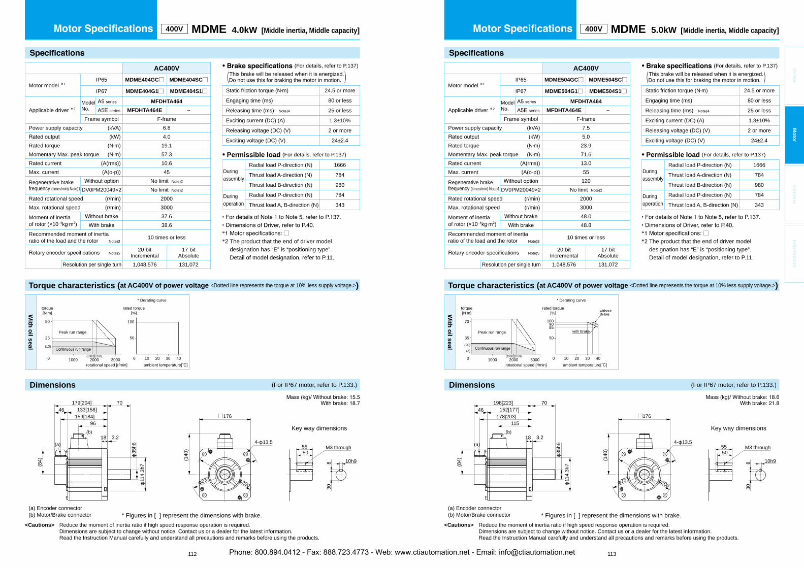
<Cautions> Reduce the moment of inertia ratio if high speed response operation is required. Dimensions are subject to change without notice. Contact us or a dealer for the latest information. Read the Instruction Manual carefully and understand all precautions and remarks before using the products.
<Cautions> Reduce the moment of inertia ratio if high speed response operation is required. Dimensions are subject to change without notice. Contact us or a dealer for the latest information. Read the Instruction Manual carefully and understand all precautions and remarks before using the products.
112 113
Driver
Mo
tor
Op
tion
sIn
form
ation
400V MDME 4.0kW [Middle inertia, Middle capacity]
AC400V
Motor model *1IP65 MDME404GC□ MDME404SC□
IP67 MDME404G1□ MDME404S1□
Applicable driver *2ModelNo.
A5 series MFDHTA464
A5E series MFDHTA464E –
Frame symbol F-framePower supply capacity (kVA) 6.8
4.0Rated torque (N m) 19.1Momentary Max. peak torque (N m) 57.3Rated current (A(rms)) 10.6Max. current (A(o-p)) 45
Regenerative brakefrequency (times/min) Note)1
No limit Note)2
DV0PM20049×2 No limit Note)2
Rated rotational speed (r/min) 2000Max. rotational speed (r/min) 3000
Moment of inertiaof rotor (×10 kg m2)
37.638.6
Recommended moment of inertia ratio of the load and the rotor Note)3
10 times or less
Note)520-bit
Incremental17-bit
AbsoluteResolution per single turn 1,048,576 131,072
• (For details, refer to P.137) This brake will be released when it is energized.(Do not use this for braking the motor in motion. )
Static friction torque (N m) 24.5 or more
Engaging time (ms) 80 or less
Releasing time (ms) Note)4 25 or less
Exciting current (DC) (A) 1.3±10%
Releasing voltage (DC) (V) 2 or more
Exciting voltage (DC) (V) 24±2.4
• Permissible load (For details, refer to P.137)
Duringassembly
Radial load P-direction (N) 1666
Thrust load A-direction (N) 784
Thrust load B-direction (N) 980
Duringoperation
Radial load P-direction (N) 784
Thrust load A, B-direction (N) 343
Torque characteristics (at AC400V of power voltage <Dotted line represents the torque at 10% less supply voltage.>)
With
oil seal
50
100
100 20 30 400 1000 2000 3000
50
25
(13)
(1900)(2100)
torque[N m]
rotational speed [r/min]
Peak run range
rated torque[%]
* Derating curve
* Figures in [ ] represent the dimensions with brake.
M3 through
(140
)
4- 13.5
□176
5550
10h9830
200233
(a) Encoder connector(b) Motor/Brake connector
Key way dimensions
46179[204] 70
18 3.2
114.
3h7
133[158]
35h6
159[184]96
(84)
(a)
(b)
400V MDME 5.0kW [Middle inertia, Middle capacity]
AC400V
Motor model *1IP65 MDME504GC□ MDME504SC□
IP67 MDME504G1□ MDME504S1□
Applicable driver *2ModelNo.
A5 series MFDHTA464
A5E series MFDHTA464E –
Frame symbol F-framePower supply capacity (kVA) 7.5
5.0Rated torque (N m) 23.9Momentary Max. peak torque (N m) 71.6Rated current (A(rms)) 13.0Max. current (A(o-p)) 55
Regenerative brakefrequency (times/min) Note)1
120DV0PM20049×2 No limit Note)2
Rated rotational speed (r/min) 2000Max. rotational speed (r/min) 3000
Moment of inertiaof rotor (×10 kg m2)
48.048.8
Recommended moment of inertia ratio of the load and the rotor Note)3
10 times or less
Note)520-bit
Incremental17-bit
AbsoluteResolution per single turn 1,048,576 131,072
• (For details, refer to P.137) This brake will be released when it is energized.(Do not use this for braking the motor in motion. )
Static friction torque (N m) 24.5 or more
Engaging time (ms) 80 or less
Releasing time (ms) Note)4 25 or less
Exciting current (DC) (A) 1.3±10%
Releasing voltage (DC) (V) 2 or more
Exciting voltage (DC) (V) 24±2.4
• Permissible load (For details, refer to P.137)
Duringassembly
Radial load P-direction (N) 1666
Thrust load A-direction (N) 784
Thrust load B-direction (N) 980
Duringoperation
Radial load P-direction (N) 784
Thrust load A, B-direction (N) 343
Torque characteristics (at AC400V of power voltage <Dotted line represents the torque at 10% less supply voltage.>)
With
oil seal
50
1009085
100 20 30 400 1000 2000 3000
70
35(20)
(3)(1900)(2100)
torque[N m]
rotational speed [r/min]
Peak run range with Brake
withoutBrake
rated torque[%]
* Derating curve
* Figures in [ ] represent the dimensions with brake.
M3 through
(140
)
4- 13.5
□176
5550
10h9830
200233
(a) Encoder connector(b) Motor/Brake connector
Key way dimensions
(84)
(a)
46198[223] 70
18 3.2
152[177]178[203]
115(b)
114.
3h7
35h6
Dimensions (For IP67 motor, refer to P.133.) Dimensions (For IP67 motor, refer to P.133.)
* □*2 The product that the end of driver model
designation has “E” is “positioning type”.Detail of model designation, refer to P.11.
* □*2 The product that the end of driver model
designation has “E” is “positioning type”.Detail of model designation, refer to P.11.
Phone: 800.894.0412 - Fax: 888.723.4773 - Web: www.ctiautomation.net - Email: [email protected]
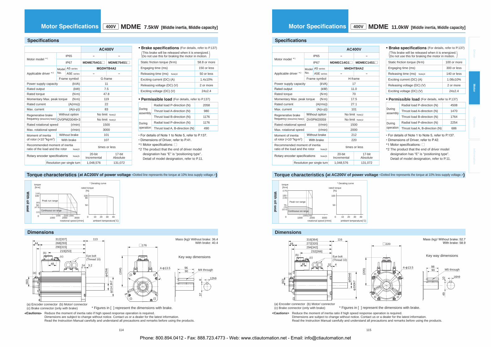
<Dotted line represents the torque at 10% less supply voltage.>)
Reduce the moment of inertia ratio if high speed response operation is required. Dimensions are subject to change without notice. Contact us or a dealer for the latest information. Read the Instruction Manual carefully and understand all precautions and remarks before using the products.
114
MDME 7.5kW ]
Motor model *1IP65 – –
IP67 MDME754G1□ MDME754S1□
Applicable driver *2Model No.
A5 series
A5E series – –
Frame symbol G-framePower supply capacity (kVA) 11Rated output (kW) 7.5Rated torque (N m) 47.8Momentary Max. peak torque (N m) 119Rated current (A(rms)) 22Max. current (A(o-p)) 83
Regenerative brakefrequency (times/min) Note)1
Without option No limit Note)2
DV0PM20049×3 No limit Note)2
Rated rotational speed (r/min) 1500Max. rotational speed (r/min) 3000
Moment of inertiaof rotor (×10 kg m2)
Without brake 101With brake 107
Recommended moment of inertia ratio of the load and the rotor Note)3
times or less
Note)520-bit
Incremental 17-bit
AbsoluteResolution per single turn 1,048,576 131,072
(a) Encoder connector (b) Motor/ connector(c) Brake connector (only with brake)
Key way dimensions
M4 through
(184
) 4- 13.5
□176
9690
12h98
200233
* Figures in [ ] represent the dimensions with brake.
(b)
(a)
(60)
44312[337] 113
24 3.2
268[293]290[315]
219[253]
48
(c)
114.
3h7
42h6
Eye bolt(Thread 10)
37
Mass (kg)/ Without brake: 36.4 With brake: 40.4
90
(47.8)
(60)
(12)
50
100
100 20 30 400 1000 2000 3000(2500)(2200)
50
100(119)
(1500)
torque[N m]
rotational speed [r/min]
Peak run range
rated torque[%]
* Derating curve
• (For details, refer to P.137) This brake will be released when it is energized. (Do not use this for braking the motor in motion. )
Static friction torque (N m) 58.8 or more
Engaging time (ms) 150 or less
Releasing time (ms) Note)4 50 or less
Exciting current (DC) (A) 1.4±10%
Releasing voltage (DC) (V) 2 or more
Exciting voltage (DC) (V) 24±2.4
• (For details, refer to P.137)
During assembly
Radial load P-direction (N) 2058
Thrust load A-direction (N) 980
Thrust load B-direction (N) 1176
Duringoperation
Radial load P-direction (N) 1176
Thrust load A, B-direction (N) 490
* □*2 The product that the end of driver model
designation has “E” is “positioning type”. Detail of model designation, refer to P.11.
Torque characteristics (at AC200V of power voltage <Dotted line represents the torque at 10% less supply voltage.>)
Dimensions
<Cautions> Reduce the moment of inertia ratio if high speed response operation is required. Dimensions are subject to change without notice. Contact us or a dealer for the latest information. Read the Instruction Manual carefully and understand all precautions and remarks before using the products.
115
Driver
Mo
tor
Op
tion
sIn
form
ation
400V MDME 11.0kW [Middle inertia, Middle capacity]
AC400V
Motor model *1IP65 – –
IP67 MDMEC14G1□ MDMEC14S1□
Applicable driver *2ModelNo.
A5 series MHDHTB4A2
A5E series – –
Frame symbol H-framePower supply capacity (kVA) 17
11.0Rated torque (N m) 70Momentary Max. peak torque (N m) 17.5Rated current (A(rms)) 27.1Max. current (A(o-p)) 101
Regenerative brakefrequency (times/min) Note)1
No limit Note)2
DV0PM20059 No limit Note)2
Rated rotational speed (r/min) 1500Max. rotational speed (r/min) 2000
Moment of inertiaof rotor (×10 kg m2)
212220
Recommended moment of inertia ratio of the load and the rotor Note)3
times or less
Note)520-bit
Incremental17-bit
AbsoluteResolution per single turn 1,048,576 131,072
(a) Encoder connector (b) Motor/ connector(c) Brake connector (only with brake)
(205
) 4- 13.5
□220
235268
* Figures in [ ] represent the dimensions with brake.
Key way dimensions
M5 through9890
16h9
1049
(b)
(a)
(60)
44316[364] 116
32 4
272[320]294[342]
232[266]
48
(c)
200h
755m
6
Eye bolt(Thread 10)
With
oil seal
50
100
100 20 30 400 1000 2000 3000
150
75
(1500)(1700)
(175)
(70)(52.5)
(130)
torque[N m]
rotational speed [r/min]
Peak run range
rated torque[%]
* Derating curve
• (For details, refer to P.137) This brake will be released when it is energized.(Do not use this for braking the motor in motion. )
Static friction torque (N m) 100 or more
Engaging time (ms) 300 or less
Releasing time (ms) Note)4 140 or less
Exciting current (DC) (A) 1.08±10%
Releasing voltage (DC) (V) 2 or more
Exciting voltage (DC) (V) 24±2.4
• Permissible load (For details, refer to P.137)
Duringassembly
Radial load P-direction (N) 4508
Thrust load A-direction (N) 1470
Thrust load B-direction (N) 1764
Duringoperation
Radial load P-direction (N) 2254
Thrust load A, B-direction (N) 686
* □*2 The product that the end of driver model
designation has “E” is “positioning type”.Detail of model designation, refer to P.11.
Phone: 800.894.0412 - Fax: 888.723.4773 - Web: www.ctiautomation.net - Email: [email protected]
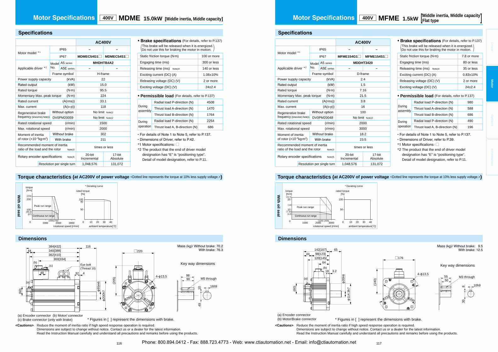
Torque characteristics (at AC200V of power voltage <Dotted line represents the torque at 10% less supply voltage.>)
Dimensions
<Cautions> Reduce the moment of inertia ratio if high speed response operation is required. Dimensions are subject to change without notice. Contact us or a dealer for the latest information. Read the Instruction Manual carefully and understand all precautions and remarks before using the products.
116 117
Driver
Mo
tor
Op
tion
sIn
form
ation
* Figures in [ ] represent the dimensions with brake.
M3 through
(140
)
4- 13.5
□176
5550
10h9830
200233
(a) Encoder connector(b) Motor/Brake connector
Key way dimensions
(60)
44142[167] 65
18 3.2
98[123]120[145]
64(b)
114.
3h7
35h6(a)
400V MDME 15.0kW [Middle inertia, Middle capacity] 400V MFME 1.5kWMiddle inertia, Middle capacity[Flat type ]
AC400V
Motor model *1IP65 – –
IP67 MFME154G1□ MFME154S1□
Applicable driver *2ModelNo.
A5 series MDDHT3420
A5E series – –
Frame symbol D-framePower supply capacity (kVA) 2.4
1.5Rated torque (N m) 7.16Momentary Max. peak torque (N m) 21.5Rated current (A(rms)) 3.8Max. current (A(o-p)) 16
Regenerative brakefrequency (times/min) Note)1
100DV0PM20048 No limit Note)2
Rated rotational speed (r/min) 2000Max. rotational speed (r/min) 3000
Moment of inertiaof rotor (×10 kg m2)
18.223.5
Recommended moment of inertia ratio of the load and the rotor Note)3
times or less
Note)520-bit
Incremental17-bit
AbsoluteResolution per single turn 1,048,576 131,072
AC400V
Motor model *1IP65 – –
IP67 MDMEC54G1□ MDMEC54S1□
Applicable driver *2ModelNo.
A5 series MHDHTB4A2
A5E series – –
Frame symbol H-framePower supply capacity (kVA) 22
15.0Rated torque (N m) 95.5Momentary Max. peak torque (N m) 224Rated current (A(rms)) 33.1Max. current (A(o-p)) 118
Regenerative brakefrequency (times/min) Note)1
No limit Note)2
DV0PM20059 No limit Note)2
Rated rotational speed (r/min) 1500Max. rotational speed (r/min) 2000
Moment of inertiaof rotor (×10 kg m2)
302211
Recommended moment of inertia ratio of the load and the rotor Note)3
times or less
Note)520-bit
Incremental17-bit
AbsoluteResolution per single turn 1,048,576 131,072
(a) Encoder connector (b) Motor/ connector(c) Brake connector (only with brake)
Key way dimensions
M5 through
(205
) 4- 13.5
□220
9890
16h9
10
235268
* Figures in [ ] represent the dimensions with brake.
(b)
(a)
(60)
44384[432] 116
32 4
340[388]362[410]
300[334]
48
(c)
200h
755
m6
Eye bolt(Thread 10)
49
With
oil seal
50
100
100 20 30 400 1000 2000 3000
10
20(21.5)
(7.16)(4.8)
(14)
(2200) (2600)
torque[N m]
rotational speed [r/min]
Peak run range
rated torque[%]
* Derating curve
With
oil seal
0 1000 2000 3000
200
100
(1500)(1700)
(224)
(95.5)(57)
90
50
100
100 20 30 40
torque[N m]
rotational speed [r/min]
Peak run range
rated torque[%]
* Derating curve
• (For details, refer to P.137) This brake will be released when it is energized.(Do not use this for braking the motor in motion. )
Static friction torque (N m) 100 or more
Engaging time (ms) 300 or less
Releasing time (ms) Note)4 140 or less
Exciting current (DC) (A) 1.08±10%
Releasing voltage (DC) (V) 2 or more
Exciting voltage (DC) (V) 24±2.4
• Permissible load (For details, refer to P.137)
Duringassembly
Radial load P-direction (N) 4508
Thrust load A-direction (N) 1470
Thrust load B-direction (N) 1764
Duringoperation
Radial load P-direction (N) 2254
Thrust load A, B-direction (N) 686
• (For details, refer to P.137) This brake will be released when it is energized.(Do not use this for braking the motor in motion. )
Static friction torque (N m) 7.8 or more
Engaging time (ms) 80 or less
Releasing time (ms) Note)4 35 or less
Exciting current (DC) (A) 0.83±10%
Releasing voltage (DC) (V) 2 or more
Exciting voltage (DC) (V) 24±2.4
• Permissible load (For details, refer to P.137)
Duringassembly
Radial load P-direction (N) 980
Thrust load A-direction (N) 588
Thrust load B-direction (N) 686
Duringoperation
Radial load P-direction (N) 490
Thrust load A, B-direction (N) 196
* □*2 The product that the end of driver model
designation has “E” is “positioning type”.Detail of model designation, refer to P.11.
* □*2 The product that the end of driver model
designation has “E” is “positioning type”.Detail of model designation, refer to P.11.
Phone: 800.894.0412 - Fax: 888.723.4773 - Web: www.ctiautomation.net - Email: [email protected]

Torque characteristics (at AC200V of power voltage <Dotted line represents the torque at 10% less supply voltage.>)
Dimensions
<Cautions> Reduce the moment of inertia ratio if high speed response operation is required. Dimensions are subject to change without notice. Contact us or a dealer for the latest information. Read the Instruction Manual carefully and understand all precautions and remarks before using the products.
Torque characteristics (at AC200V of power voltage <Dotted line represents the torque at 10% less supply voltage.>)
Dimensions
<Cautions> Reduce the moment of inertia ratio if high speed response operation is required. Dimensions are subject to change without notice. Contact us or a dealer for the latest information. Read the Instruction Manual carefully and understand all precautions and remarks before using the products.
118 119
Driver
Mo
tor
Op
tion
sIn
form
ation
400V MFME 2.5kWMiddle inertia, Middle capacity[Flat type ] 400V MFME 4.5kW
Middle inertia, Middle capacity[Flat type ]
AC400V
Motor model *1IP65 – –
IP67 MFME454G1□ MFME454S1□
Applicable driver *2ModelNo.
A5 series MFDHTA464
A5E series – –
Frame symbol F-framePower supply capacity (kVA) 6.9
4.5Rated torque (N m) 21.5Momentary Max. peak torque (N m) 54.9Rated current (A(rms)) 12.4Max. current (A(o-p)) 53
Regenerative brakefrequency (times/min) Note)1
67DV0PM20049×2 375
Rated rotational speed (r/min) 2000Max. rotational speed (r/min) 3000
Moment of inertiaof rotor (×10 kg m2)
63.170.9
Recommended moment of inertia ratio of the load and the rotor Note)3
times or less
Note)520-bit
Incremental17-bit
AbsoluteResolution per single turn 1,048,576 131,072
AC400V
Motor model *1IP65 – –
IP67 MFME254G1□ MFME254S1□
Applicable driver *2ModelNo.
A5 series MEDHT4430
A5E series – –
Frame symbol E-framePower supply capacity (kVA) 3.9
2.5Rated torque (N m) 11.9Momentary Max. peak torque (N m) 30.4Rated current (A(rms)) 6.7Max. current (A(o-p)) 29
Regenerative brakefrequency (times/min) Note)1
75DV0PM20049 No limit Note)2
Rated rotational speed (r/min) 2000Max. rotational speed (r/min) 3000
Moment of inertiaof rotor (×10 kg m2)
35.845.2
Recommended moment of inertia ratio of the load and the rotor Note)3
times or less
Note)520-bit
Incremental17-bit
AbsoluteResolution per single turn 1,048,576 131,072
* Figures in [ ] represent the dimensions with brake.
M3 through
(162
)
4- 13.5
□220
5550
10h9830
235268
(a) Encoder connector(b) Motor/Brake connector
Key way dimensions
(60)
44135[168] 65
16 4
91[124]113[146]
54
(b)
200h
735h6
(a)
* Figures in [ ] represent the dimensions with brake.
M3 through
(162
)
4- 13.5
□220
5550
10h9830
235268
(a) Encoder connector(b) Motor/Brake connector
Key way dimensions
44155[188] 70
16 4
111[144]133[166]
74
(b)
200h
735h6
(a)
(60)
With
oil seal
50
100
100 20 30 400 1000 2000 3000
25
50(54.9)
(21.5)(10)
(1800)
torque[N m]
rotational speed [r/min]
Peak run range
rated torque[%]
* Derating curve
With
oil seal
50
100
100 20 30 400 1000 2000 3000
15
30(30.4)
(11.9)(5)
(1800)
torque[N m]
rotational speed [r/min]
Peak run range
rated torque[%]
* Derating curve
• (For details, refer to P.137) This brake will be released when it is energized.(Do not use this for braking the motor in motion. )
Static friction torque (N m) 21.6 or more
Engaging time (ms) 150 or less
Releasing time (ms) Note)4 100 or less
Exciting current (DC) (A) 0.75±10%
Releasing voltage (DC) (V) 2 or more
Exciting voltage (DC) (V) 24±2.4
• Permissible load (For details, refer to P.137)
Duringassembly
Radial load P-direction (N) 1862
Thrust load A-direction (N) 686
Thrust load B-direction (N) 686
Duringoperation
Radial load P-direction (N) 784
Thrust load A, B-direction (N) 294
• (For details, refer to P.137) This brake will be released when it is energized.(Do not use this for braking the motor in motion. )
Static friction torque (N m) 31.4 or more
Engaging time (ms) 150 or less
Releasing time (ms) Note)4 100 or less
Exciting current (DC) (A) 0.75±10%
Releasing voltage (DC) (V) 2 or more
Exciting voltage (DC) (V) 24±2.4
• Permissible load (For details, refer to P.137)
Duringassembly
Radial load P-direction (N) 1862
Thrust load A-direction (N) 686
Thrust load B-direction (N) 686
Duringoperation
Radial load P-direction (N) 784
Thrust load A, B-direction (N) 294
* □*2 The product that the end of driver model
designation has “E” is “positioning type”.Detail of model designation, refer to P.11.
* □*2 The product that the end of driver model
designation has “E” is “positioning type”.Detail of model designation, refer to P.11.
Phone: 800.894.0412 - Fax: 888.723.4773 - Web: www.ctiautomation.net - Email: [email protected]

<Cautions> Reduce the moment of inertia ratio if high speed response operation is required. Dimensions are subject to change without notice. Contact us or a dealer for the latest information. Read the Instruction Manual carefully and understand all precautions and remarks before using the products.
<Cautions> Reduce the moment of inertia ratio if high speed response operation is required. Dimensions are subject to change without notice. Contact us or a dealer for the latest information. Read the Instruction Manual carefully and understand all precautions and remarks before using the products.
120 121
Driver
Mo
tor
Op
tion
sIn
form
ation
400V MGME 0.9kW [Middle inertia, Middle capacity]
AC400V
Motor model *1IP65 MGME094GC□ MGME094SC□
IP67 MGME094G1□ MGME094S1□
Applicable driver *2ModelNo.
A5 series MDDHT3420
A5E series MDDHT3420E –
Frame symbol D-framePower supply capacity (kVA) 1.8
0.9Rated torque (N m) 8.59Momentary Max. peak torque (N m) 19.3Rated current (A(rms)) 3.8Max. current (A(o-p)) 12
Regenerative brakefrequency (times/min) Note)1
No limit Note)2
DV0PM20048 No limit Note)2
Rated rotational speed (r/min) 1000Max. rotational speed (r/min) 2000
Moment of inertiaof rotor (×10 kg m2)
6.707.99
Recommended moment of inertia ratio of the load and the rotor Note)3
10 times or less
Note)520-bit
Incremental17-bit
AbsoluteResolution per single turn 1,048,576 131,072
• (For details, refer to P.137) This brake will be released when it is energized.(Do not use this for braking the motor in motion. )
Static friction torque (N m) 13.7 or more
Engaging time (ms) 100 or less
Releasing time (ms) Note)4 50 or less
Exciting current (DC) (A) 0.79±10%
Releasing voltage (DC) (V) 2 or more
Exciting voltage (DC) (V) 24±2.4
• Permissible load (For details, refer to P.137)
Duringassembly
Radial load P-direction (N) 980
Thrust load A-direction (N) 588
Thrust load B-direction (N) 686
Duringoperation
Radial load P-direction (N) 686
Thrust load A, B-direction (N) 196
Torque characteristics (at AC400V of power voltage <Dotted line represents the torque at 10% less supply voltage.>)
With
oil seal
50
100
100 20 30 400 1000 2000 3000
20
10(8)
(4.3)
(14)
(1600)(1800)
torque[N m]
rotational speed [r/min]
Peak run range
rated torque[%]
* Derating curve
* Figures in [ ] represent the dimensions with brake.
M3 through
(116
) 4- 9
□130
165
4541
8h9718
145
(a) Encoder connector(b) Motor/Brake connector
Key way dimensions
46157.5[182.5] 70
12 6
110h
7
111.5[136.5]
77.5137.5[162.5]
22h6
(b)(a)
(84)
400V MGME 2.0kW [Middle inertia, Middle capacity]
AC400V
Motor model *1IP65 MGME204GC□ MGME204SC□
IP67 MGME204G1□ MGME204S1□
Applicable driver *2ModelNo.
A5 series MFDHT5440
A5E series MFDHT5440E –
Frame symbol F-framePower supply capacity (kVA) 3.8
2.0Rated torque (N m) 19.1Momentary Max. peak torque (N m) 47.7Rated current (A(rms)) 8.5Max. current (A(o-p)) 30
Regenerative brakefrequency (times/min) Note)1
No limit Note)2
DV0PM20049×2 No limit Note)2
Rated rotational speed (r/min) 1000Max. rotational speed (r/min) 2000
Moment of inertiaof rotor (×10 kg m2)
30.331.4
Recommended moment of inertia ratio of the load and the rotor Note)3
10 times or less
Note)520-bit
Incremental17-bit
AbsoluteResolution per single turn 1,048,576 131,072
• (For details, refer to P.137) This brake will be released when it is energized.(Do not use this for braking the motor in motion. )
Static friction torque (N m) 24.5 or more
Engaging time (ms) 80 or less
Releasing time (ms) Note)4 25 or less
Exciting current (DC) (A) 1.3±10%
Releasing voltage (DC) (V) 2 or more
Exciting voltage (DC) (V) 24±2.4
• Permissible load (For details, refer to P.137)
Duringassembly
Radial load P-direction (N) 1666
Thrust load A-direction (N) 784
Thrust load B-direction (N) 980
Duringoperation
Radial load P-direction (N) 1176
Thrust load A, B-direction (N) 490
Torque characteristics (at AC400V of power voltage <Dotted line represents the torque at 10% less supply voltage.>)
With
oil seal
50
100
100 20 30 400 1000 2000 3000
50
25(18)
(9.6)
(28)
(1400)(1600)
torque[N m]
rotational speed [r/min]
Peak run range
rated torque[%]
* Derating curve
* Figures in [ ] represent the dimensions with brake.
M3 through
(140
)
4- 13.5
□176
5550
10h9830
200233
(a) Encoder connector(b) Motor/Brake connector
Key way dimensions
46165.5[190.5] 80
18 3.2
114.
3h7
119.5[144.5]
35h6
145.5[170.5]82.5(b)
(84)
(a)
Dimensions (For IP67 motor, refer to P.134.) Dimensions (For IP67 motor, refer to P.134.)
* □*2 The product that the end of driver model
designation has “E” is “positioning type”.Detail of model designation, refer to P.11.
* □*2 The product that the end of driver model
designation has “E” is “positioning type”.Detail of model designation, refer to P.11.
Phone: 800.894.0412 - Fax: 888.723.4773 - Web: www.ctiautomation.net - Email: [email protected]

Torque characteristics (at AC200V of power voltage <Dotted line represents the torque at 10% less supply voltage.>)
Dimensions
<Cautions> Reduce the moment of inertia ratio if high speed response operation is required. Dimensions are subject to change without notice. Contact us or a dealer for the latest information. Read the Instruction Manual carefully and understand all precautions and remarks before using the products.
<Cautions> Reduce the moment of inertia ratio if high speed response operation is required. Dimensions are subject to change without notice. Contact us or a dealer for the latest information. Read the Instruction Manual carefully and understand all precautions and remarks before using the products.
122 123
Driver
Mo
tor
Op
tion
sIn
form
ation
400V MGME 3.0kW [Middle inertia, Middle capacity]
AC400V
Motor model *1IP65 MGME304GC□ MGME304SC□
IP67 MGME304G1□ MGME304S1□
Applicable driver *2ModelNo.
A5 series MFDHTA464
A5E series MFDHTA464E –
Frame symbol F-framePower supply capacity (kVA) 4.5
3.0Rated torque (N m) 28.7Momentary Max. peak torque (N m) 71.7Rated current (A(rms)) 11.3Max. current (A(o-p)) 40
Regenerative brakefrequency (times/min) Note)1
No limit Note)2
DV0PM20049×2 No limit Note)2
Rated rotational speed (r/min) 1000Max. rotational speed (r/min) 2000
Moment of inertiaof rotor (×10 kg m2)
48.449.2
Recommended moment of inertia ratio of the load and the rotor Note)3
10 times or less
Note)520-bit
Incremental17-bit
AbsoluteResolution per single turn 1,048,576 131,072
• (For details, refer to P.137) This brake will be released when it is energized.(Do not use this for braking the motor in motion. )
Static friction torque (N m) 58.8 or more
Engaging time (ms) 150 or less
Releasing time (ms) Note)4 50 or less
Exciting current (DC) (A) 1.4±10%
Releasing voltage (DC) (V) 2 or more
Exciting voltage (DC) (V) 24±2.4
• Permissible load (For details, refer to P.137)
Duringassembly
Radial load P-direction (N) 2058
Thrust load A-direction (N) 980
Thrust load B-direction (N) 1176
Duringoperation
Radial load P-direction (N) 1470
Thrust load A, B-direction (N) 490
Torque characteristics (at AC400V of power voltage <Dotted line represents the torque at 10% less supply voltage.>)
With
oil seal
50
100
100 20 30 400 1000 2000 3000
70
35
(20)(14)
(40)
(1400)(1600)
torque[N m]
rotational speed [r/min]
rated torque[%]
* curve
* Figures in [ ] represent the dimensions with brake.
M3 through
(140
)
4- 13.5
□176
5550
10h9830
200233
(a) Encoder connector(b) Motor/Brake connector
Key way dimensions
(84)
(a)
46211.5[236.5] 80
18 3.2
165.5[190.5]191.5[216.5]
128.5(b)
114.
3h7
35h6
400V MGME 4.5kW [Middle inertia, Middle capacity]
AC400V
Motor model *1IP65 – –
IP67 MGME454G1□ MGME454S1□
Applicable driver *2ModelNo.
A5 series MFDHTA464
A5E series MFDHTA464E –
Frame symbol F-framePower supply capacity (kVA) 7.5
4.5Rated torque (N m) 43.0Momentary Max. peak torque (N m) 107Rated current (A(rms)) 14.8Max. current (A(o-p)) 55
Regenerative brakefrequency (times/min) Note)1
No limit Note)2
DV0PM20049×2 No limit Note)2
Rated rotational speed (r/min) 1000Max. rotational speed (r/min) 2000
Moment of inertiaof rotor (×10 kg m2)
79.184.4
Recommended moment of inertia ratio of the load and the rotor Note)3
times or less
Note)520-bit
Incremental17-bit
AbsoluteResolution per single turn 1,048,576 131,072
• (For details, refer to P.137) This brake will be released when it is energized.(Do not use this for braking the motor in motion. )
Static friction torque (N m) 58.8 or more
Engaging time (ms) 150 or less
Releasing time (ms) Note)4 50 or less
Exciting current (DC) (A) 1.4±10%
Releasing voltage (DC) (V) 2 or more
Exciting voltage (DC) (V) 24±2.4
• Permissible load (For details, refer to P.137)
Duringassembly
Radial load P-direction (N) 2058
Thrust load A-direction (N) 980
Thrust load B-direction (N) 1176
Duringoperation
Radial load P-direction (N) 1470
Thrust load A, B-direction (N) 490
* Figures in [ ] represent the dimensions with brake.
(140
)
4- 13.5
□176
200233
(a) Encoder connector(b) Motor/Brake connector
Key way dimensions
M4 through9690
12h9837
(b)
(a)(6
0)
44113
24 3.2
114.
3h7
42h6
266[291]222[247]244[269]
185 Eye bolt(Thread 10)
With
oil seal
(70)
(107)
50
100
100 20 30 400 1000 2000 3000
100
50(43)(22)
(1500)(1700)
torque[N m]
rotational speed [r/min]
Peak run range
rated torque[%]
* Derating curve
Dimensions (For IP67 motor, refer to P.134.)
* □*2 The product that the end of driver model
designation has “E” is “positioning type”.Detail of model designation, refer to P.11.
* □*2 The product that the end of driver model
designation has “E” is “positioning type”.Detail of model designation, refer to P.11.
Phone: 800.894.0412 - Fax: 888.723.4773 - Web: www.ctiautomation.net - Email: [email protected]

Torque characteristics (at AC200V of power voltage <Dotted line represents the torque at 10% less supply voltage.>)
<Cautions> Reduce the moment of inertia ratio if high speed response operation is required. Dimensions are subject to change without notice. Contact us or a dealer for the latest information. Read the Instruction Manual carefully and understand all precautions and remarks before using the products.
Torque characteristics (at AC200V of power voltage <Dotted line represents the torque at 10% less supply voltage.>)
Dimensions
<Cautions> Reduce the moment of inertia ratio if high speed response operation is required. Dimensions are subject to change without notice. Contact us or a dealer for the latest information. Read the Instruction Manual carefully and understand all precautions and remarks before using the products.
124 125
Driver
Mo
tor
Op
tion
sIn
form
ation
400V MGME 6.0kW [Middle inertia, Middle capacity] 400V MHME 1.0kW [High inertia, Middle capacity]
AC400V
Motor model *1IP65 MHME104GC□ MHME104SC□
IP67 MHME104G1□ MHME104S1□
Applicable driver *2ModelNo.
A5 series MDDHT2412
A5E series MDDHT2412E –
Frame symbol D-framePower supply capacity (kVA) 1.8
1.0Rated torque (N m) 4.77Momentary Max. peak torque (N m) 14.3Rated current (A(rms)) 2.9Max. current (A(o-p)) 12
Regenerative brakefrequency (times/min) Note)1
83DV0PM20048 No limit Note)2
Rated rotational speed (r/min) 2000Max. rotational speed (r/min) 3000
Moment of inertiaof rotor (×10 kg m2)
24.726.0
Recommended moment of inertia ratio of the load and the rotor Note)3
5 times or less
Note)520-bit
Incremental17-bit
AbsoluteResolution per single turn 1,048,576 131,072
• (For details, refer to P.137) This brake will be released when it is energized.(Do not use this for braking the motor in motion. )
Static friction torque (N m) 4.9 or more
Engaging time (ms) 80 or less
Releasing time (ms) Note)4 70 or less
Exciting current (DC) (A) 0.59±10%
Releasing voltage (DC) (V) 2 or more
Exciting voltage (DC) (V) 24±2.4
• Permissible load (For details, refer to P.137)
Duringassembly
Radial load P-direction (N) 980
Thrust load A-direction (N) 588
Thrust load B-direction (N) 686
Duringoperation
Radial load P-direction (N) 490
Thrust load A, B-direction (N) 196
Torque characteristics (at AC400V of power voltage <Dotted line represents the torque at 10% less supply voltage.>)
With
oil seal
50
100
100 20 30 400 1000 2000 3000
15
10
5
(2200)
(3.2)(4.0)
(6.0)
torque[N m]
rotational speed [r/min]
Peak run range
rated torque[%]
* Derating curve
* Figures in [ ] represent the dimensions with brake.
M3 through
(116
) 4- 9
□130
165
4541
8h9718
145
(a) Encoder connector(b) Motor/Brake connector
Key way dimensions
46175[200] 70
12 6
110h
7
129[154]
22h6
155[180]95
(b)(a)
(84)
AC400V
Motor model *1IP65 – –
IP67 MGME604G1□ MGME604S1□
Applicable driver *2ModelNo.
A5 series MGDHTB4A2
A5E series – –
Frame symbol G-framePower supply capacity (kVA) 9.0
6.0Rated torque (N m) 57.3Momentary Max. peak torque (N m) 143Rated current (A(rms)) 19.4Max. current (A(o-p)) 74
Regenerative brakefrequency (times/min) Note)1
No limit Note)2
DV0PM20049×3 No limit Note)2
Rated rotational speed (r/min) 1000Max. rotational speed (r/min) 2000
Moment of inertiaof rotor (×10 kg m2)
101107
Recommended moment of inertia ratio of the load and the rotor Note)3
times or less
Note)520-bit
Incremental17-bit
AbsoluteResolution per single turn 1,048,576 131,072
(a) Encoder connector (b) Motor/ connector(c) Brake connector (only with brake)
Key way dimensions
M4 through
(184
) 4- 13.5
□176
9690
12h98
200233
* Figures in [ ] represent the dimensions with brake.
(b)
(a)
(60)
44312[337] 113
24 3.2
268[293]290[315]
219[253]
48
(c)
114.
3h7
42h6
Eye bolt(Thread 10)
37
With
oil seal
(143)
(57.3)(28)
(100)
50
100
100 20 30 400 1000 2000 3000
150
75
(1500)(1700)
torque[N m]
rotational speed [r/min]
Peak run range
rated torque[%]
* Derating curve
Dimensions (For IP67 motor, refer to P.135.)
• (For details, refer to P.137) This brake will be released when it is energized.(Do not use this for braking the motor in motion. )
Static friction torque (N m) 58.8 or more
Engaging time (ms) 150 or less
Releasing time (ms) Note)4 50 or less
Exciting current (DC) (A) 1.4±10%
Releasing voltage (DC) (V) 2 or more
Exciting voltage (DC) (V) 24±2.4
• Permissible load (For details, refer to P.137)
Duringassembly
Radial load P-direction (N) 2058
Thrust load A-direction (N) 980
Thrust load B-direction (N) 1176
Duringoperation
Radial load P-direction (N) 1764
Thrust load A, B-direction (N) 588
* □*2 The product that the end of driver model
designation has “E” is “positioning type”.Detail of model designation, refer to P.11.
* □*2 The product that the end of driver model
designation has “E” is “positioning type”.Detail of model designation, refer to P.11.
Phone: 800.894.0412 - Fax: 888.723.4773 - Web: www.ctiautomation.net - Email: [email protected]

<Cautions> Reduce the moment of inertia ratio if high speed response operation is required. Dimensions are subject to change without notice. Contact us or a dealer for the latest information. Read the Instruction Manual carefully and understand all precautions and remarks before using the products.
<Cautions> Reduce the moment of inertia ratio if high speed response operation is required. Dimensions are subject to change without notice. Contact us or a dealer for the latest information. Read the Instruction Manual carefully and understand all precautions and remarks before using the products.
126 127
Driver
Mo
tor
Op
tion
sIn
form
ation
400V MHME 1.5kW [High inertia, Middle capacity]
AC400V
Motor model *1IP65 MHME154GC□ MHME154SC□
IP67 MHME154G1□ MHME154S1□
Applicable driver *2ModelNo.
A5 series MDDHT3420
A5E series MDDHT3420E –
Frame symbol D-framePower supply capacity (kVA) 2.3
1.5Rated torque (N m) 7.16Momentary Max. peak torque (N m) 21.5Rated current (A(rms)) 4.7Max. current (A(o-p)) 20
Regenerative brakefrequency (times/min) Note)1
22DV0PM20048 130
Rated rotational speed (r/min) 2000Max. rotational speed (r/min) 3000
Moment of inertiaof rotor (×10 kg m2)
37.138.4
Recommended moment of inertia ratio of the load and the rotor Note)3
5 times or less
Note)520-bit
Incremental17-bit
AbsoluteResolution per single turn 1,048,576 131,072
• (For details, refer to P.137) This brake will be released when it is energized.(Do not use this for braking the motor in motion. )
Static friction torque (N m) 13.7 or more
Engaging time (ms) 100 or less
Releasing time (ms) Note)4 50 or less
Exciting current (DC) (A) 0.79±10%
Releasing voltage (DC) (V) 2 or more
Exciting voltage (DC) (V) 24±2.4
• Permissible load (For details, refer to P.137)
Duringassembly
Radial load P-direction (N) 980
Thrust load A-direction (N) 588
Thrust load B-direction (N) 686
Duringoperation
Radial load P-direction (N) 490
Thrust load A, B-direction (N) 196
Torque characteristics (at AC400V of power voltage <Dotted line represents the torque at 10% less supply voltage.>)
With
oil seal
50
100
100 20 30 400 1000 2000 3000
20
10(6.0)(4.8)
(2300)
torque[N m]
rotational speed [r/min]
Peak run range
rated torque[%]
* Derating curve
* Figures in [ ] represent the dimensions with brake.
M3 through4541
8h9718
(a) Encoder connector(b) Motor/Brake connector
Key way dimensions
(116
) 4- 9
□130
165145
46192.5[217.5] 70
12 6
146.5[171.5]
22h6
172.5[197.5]112.5
(b)
110h
7
(a)
(84)
400V MHME 2.0kW [High inertia, Middle capacity]
AC400V
Motor model *1IP65 MHME204GC□ MHME204SC□
IP67 MHME204G1□ MHME204S1□
Applicable driver *2ModelNo.
A5 series MEDHT4430
A5E series MEDHT4430E –
Frame symbol E-framePower supply capacity (kVA) 3.3
2.0Rated torque (N m) 9.55Momentary Max. peak torque (N m) 28.6Rated current (A(rms)) 5.5Max. current (A(o-p)) 24
Regenerative brakefrequency (times/min) Note)1
45DV0PM20048 142
Rated rotational speed (r/min) 2000Max. rotational speed (r/min) 3000
Moment of inertiaof rotor (×10 kg m2)
57.859.6
Recommended moment of inertia ratio of the load and the rotor Note)3
5 times or less
Note)520-bit
Incremental17-bit
AbsoluteResolution per single turn 1,048,576 131,072
• (For details, refer to P.137) This brake will be released when it is energized.(Do not use this for braking the motor in motion. )
Static friction torque (N m) 24.5 or more
Engaging time (ms) 80 or less
Releasing time (ms) Note)4 25 or less
Exciting current (DC) (A) 1.3±10%
Releasing voltage (DC) (V) 2 or more
Exciting voltage (DC) (V) 24±2.4
• Permissible load (For details, refer to P.137)
Duringassembly
Radial load P-direction (N) 1666
Thrust load A-direction (N) 784
Thrust load B-direction (N) 980
Duringoperation
Radial load P-direction (N) 784
Thrust load A, B-direction (N) 343
Torque characteristics (at AC400V of power voltage <Dotted line represents the torque at 10% less supply voltage.>)
With
oil seal
50
100
100 20 30 400 1000 2000 3000
30
15
(2200)
(6.4)
torque[N m]
rotational speed [r/min]
Peak run range
rated torque[%]
* Derating curve
* Figures in [ ] represent the dimensions with brake.
M3 through
(140
)
4- 13.5
□176
5550
10h9830
200233
(a) Encoder connector(b) Motor/Brake connector
Key way dimensions
4680
18 3.2
133[158]179[204]
159[184]96
(b)
114.
3h7
35h6
(84)
(a)
Dimensions (For IP67 motor, refer to P.135.) Dimensions (For IP67 motor, refer to P.135.)
* □*2 The product that the end of driver model
designation has “E” is “positioning type”.Detail of model designation, refer to P.11.
* □*2 The product that the end of driver model
designation has “E” is “positioning type”.Detail of model designation, refer to P.11.
Phone: 800.894.0412 - Fax: 888.723.4773 - Web: www.ctiautomation.net - Email: [email protected]
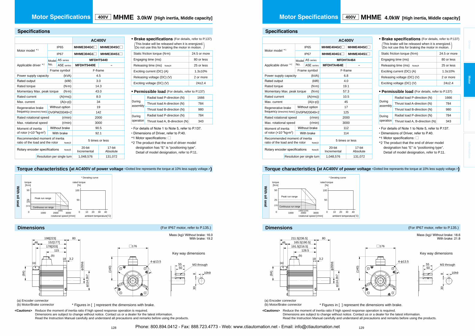
<Cautions> Reduce the moment of inertia ratio if high speed response operation is required. Dimensions are subject to change without notice. Contact us or a dealer for the latest information. Read the Instruction Manual carefully and understand all precautions and remarks before using the products.
<Cautions> Reduce the moment of inertia ratio if high speed response operation is required. Dimensions are subject to change without notice. Contact us or a dealer for the latest information. Read the Instruction Manual carefully and understand all precautions and remarks before using the products.
128 129
Driver
Mo
tor
Op
tion
sIn
form
ation
400V MHME 3.0kW [High inertia, Middle capacity]
AC400V
Motor model *1IP65 MHME304GC□ MHME304SC□
IP67 MHME304G1□ MHME304S1□
Applicable driver *2ModelNo.
A5 series MFDHT5440
A5E series MFDHT5440E –
Frame symbol F-framePower supply capacity (kVA) 4.5
3.0Rated torque (N m) 14.3Momentary Max. peak torque (N m) 43.0Rated current (A(rms)) 8.0Max. current (A(o-p)) 34
Regenerative brakefrequency (times/min) Note)1
19DV0PM20049×2 142
Rated rotational speed (r/min) 2000Max. rotational speed (r/min) 3000
Moment of inertiaof rotor (×10 kg m2)
90.592.1
Recommended moment of inertia ratio of the load and the rotor Note)3
5 times or less
Note)520-bit
Incremental17-bit
AbsoluteResolution per single turn 1,048,576 131,072
• (For details, refer to P.137) This brake will be released when it is energized.(Do not use this for braking the motor in motion. )
Static friction torque (N m) 24.5 or more
Engaging time (ms) 80 or less
Releasing time (ms) Note)4 25 or less
Exciting current (DC) (A) 1.3±10%
Releasing voltage (DC) (V) 2 or more
Exciting voltage (DC) (V) 24±2.4
• Permissible load (For details, refer to P.137)
Duringassembly
Radial load P-direction (N) 1666
Thrust load A-direction (N) 784
Thrust load B-direction (N) 980
Duringoperation
Radial load P-direction (N) 784
Thrust load A, B-direction (N) 343
Torque characteristics (at AC400V of power voltage <Dotted line represents the torque at 10% less supply voltage.>)
With
oil seal
50
100
100 20 30 400 1000 2000 3000
50
25
(9.5)
(20)
(2400)
torque[N m]
rotational speed [r/min]
Peak run range
rated torque[%]
* Derating curve
* Figures in [ ] represent the dimensions with brake.
M3 through
(140
)
4- 13.5
□176
5550
10h9830
200233
(a) Encoder connector(b) Motor/Brake connector
Key way dimensions
4680
18 3.2
152[177]198[223]
178[203]115
(b)
114.
3h7
35h6
(84)
(a)
400V MHME 4.0kW [High inertia, Middle capacity]
AC400V
Motor model *1IP65 MHME404GC□ MHME404SC□
IP67 MHME404G1□ MHME404S1□
Applicable driver *2ModelNo.
A5 series MFDHTA464
A5E series MFDHTA464E –
Frame symbol F-framePower supply capacity (kVA) 6.8
4.0Rated torque (N m) 19.1Momentary Max. peak torque (N m) 57.3Rated current (A(rms)) 10.5Max. current (A(o-p)) 45
Regenerative brakefrequency (times/min) Note)1
17DV0PM20049×2 125
Rated rotational speed (r/min) 2000Max. rotational speed (r/min) 3000
Moment of inertiaof rotor (×10 kg m2)
112114
Recommended moment of inertia ratio of the load and the rotor Note)3
5 times or less
Note)520-bit
Incremental17-bit
AbsoluteResolution per single turn 1,048,576 131,072
• (For details, refer to P.137) This brake will be released when it is energized.(Do not use this for braking the motor in motion. )
Static friction torque (N m) 24.5 or more
Engaging time (ms) 80 or less
Releasing time (ms) Note)4 25 or less
Exciting current (DC) (A) 1.3±10%
Releasing voltage (DC) (V) 2 or more
Exciting voltage (DC) (V) 24±2.4
• Permissible load (For details, refer to P.137)
Duringassembly
Radial load P-direction (N) 1666
Thrust load A-direction (N) 784
Thrust load B-direction (N) 980
Duringoperation
Radial load P-direction (N) 784
Thrust load A, B-direction (N) 343
Torque characteristics (at AC400V of power voltage <Dotted line represents the torque at 10% less supply voltage.>)
With
oil seal
50
100
100 20 30 400 1000 2000 3000
50
25
(13)
(2100)(1900)
torque[N m]
rotational speed [r/min]
Peak run range
rated torque[%]
* Derating curve
* Figures in [ ] represent the dimensions with brake.
M3 through
(140
)
4- 13.5
□176
5550
10h9830
200233
(a) Encoder connector(b) Motor/Brake connector
Key way dimensions
4680
18 3.2
165.5[190.5]211.5[236.5]
191.5[216.5]128.5
(b)
114.
3h7
35h6
(84)
(a)
Dimensions (For IP67 motor, refer to P.135.) Dimensions (For IP67 motor, refer to P.135.)
* □*2 The product that the end of driver model
designation has “E” is “positioning type”.Detail of model designation, refer to P.11.
* □*2 The product that the end of driver model
designation has “E” is “positioning type”.Detail of model designation, refer to P.11.
Phone: 800.894.0412 - Fax: 888.723.4773 - Web: www.ctiautomation.net - Email: [email protected]
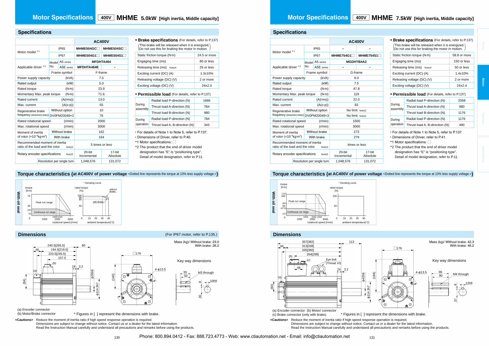
Dimensions
<Cautions> Reduce the moment of inertia ratio if high speed response operation is required. Dimensions are subject to change without notice. Contact us or a dealer for the latest information. Read the Instruction Manual carefully and understand all precautions and remarks before using the products.
<Cautions> Reduce the moment of inertia ratio if high speed response operation is required. Dimensions are subject to change without notice. Contact us or a dealer for the latest information. Read the Instruction Manual carefully and understand all precautions and remarks before using the products.
130 131
Driver
Mo
tor
Op
tion
sIn
form
ation
400V MHME 7.5kW [High inertia, Middle capacity]
AC400V
Motor model *1IP65 – –
IP67 MHME754G1□ MHME754S1□
Applicable driver *2ModelNo.
A5 series MGDHTB4A2
A5E series – –
Frame symbol G-framePower supply capacity (kVA) 9.0
7.5Rated torque (N m) 47.8Momentary Max. peak torque (N m) 119Rated current (A(rms)) 22.0Max. current (A(o-p)) 83
Regenerative brakefrequency (times/min) Note)1
No limit Note)2
DV0PM20049×3 No limit Note)2
Rated rotational speed (r/min) 1500Max. rotational speed (r/min) 3000
Moment of inertiaof rotor (×10 kg m2)
273279
Recommended moment of inertia ratio of the load and the rotor Note)3
times or less
Note)520-bit
Incremental17-bit
AbsoluteResolution per single turn 1,048,576 131,072
• (For details, refer to P.137) This brake will be released when it is energized.(Do not use this for braking the motor in motion. )
Static friction torque (N m) 58.8 or more
Engaging time (ms) 150 or less
Releasing time (ms) Note)4 50 or less
Exciting current (DC) (A) 1.4±10%
Releasing voltage (DC) (V) 2 or more
Exciting voltage (DC) (V) 24±2.4
• Permissible load (For details, refer to P.137)
Duringassembly
Radial load P-direction (N) 2058
Thrust load A-direction (N) 980
Thrust load B-direction (N) 1176
Duringoperation
Radial load P-direction (N) 1176
Thrust load A, B-direction (N) 490
Torque characteristics (at AC400V of power voltage <Dotted line represents the torque at 10% less supply voltage.>)
With
oil seal
(47.8)
(12)
(60)50
100
100 20 30 400 1000 2000 3000(2500)(2200)
50
100(119)
(1500)
torque[N m]
rotational speed [r/min]
Peak run range
rated torque[%]
* Derating curve
400V MHME 5.0kW [High inertia, Middle capacity]
AC400V
Motor model *1IP65 MHME504GC□ MHME504SC□
IP67 MHME504G1□ MHME504S1□
Applicable driver *2ModelNo.
A5 series MFDHTA464
A5E series MFDHTA464E –
Frame symbol F-framePower supply capacity (kVA) 7.5
5.0Rated torque (N m) 23.9Momentary Max. peak torque (N m) 71.6Rated current (A(rms)) 13.0Max. current (A(o-p)) 55
Regenerative brakefrequency (times/min) Note)1
10DV0PM20049×2 76
Rated rotational speed (r/min) 2000Max. rotational speed (r/min) 3000
Moment of inertiaof rotor (×10 kg m2)
162164
Recommended moment of inertia ratio of the load and the rotor Note)3
5 times or less
Note)520-bit
Incremental17-bit
AbsoluteResolution per single turn 1,048,576 131,072
• (For details, refer to P.137) This brake will be released when it is energized.(Do not use this for braking the motor in motion. )
Static friction torque (N m) 24.5 or more
Engaging time (ms) 80 or less
Releasing time (ms) Note)4 25 or less
Exciting current (DC) (A) 1.3±10%
Releasing voltage (DC) (V) 2 or more
Exciting voltage (DC) (V) 24±2.4
• Permissible load (For details, refer to P.137)
Duringassembly
Radial load P-direction (N) 1666
Thrust load A-direction (N) 784
Thrust load B-direction (N) 980
Duringoperation
Radial load P-direction (N) 784
Thrust load A, B-direction (N) 343
Torque characteristics (at AC400V of power voltage <Dotted line represents the torque at 10% less supply voltage.>)
* Figures in [ ] represent the dimensions with brake.
M3 through
(140
)
4- 13.5
□176
5550
10h9830
200233
(a) Encoder connector(b) Motor/Brake connector
Key way dimensions
4680
18 3.2
194.5[219.5]240.5[265.5]
220.5[245.5]157.5
(b)
114.
3h7
35h6
(84)
(a)
With
oil seal
50
1009085
100 20 30 400 1000 2000 3000
70
35(20)(3)
(2100)(1900)
torque[N m]
rotational speed [r/min]
Peak run range with Brake
withoutBrake
rated torque[%]
* Derating curve
(a) Encoder connector (b) Motor/ connector(c) Brake connector (only with brake)
Key way dimensions
M4 through
(184
) 4- 13.5
□176
9690
12h98
200233
* Figures in [ ] represent the dimensions with brake.
(b)
(a)
(60)
44113
24 3.248
(c)
114.
3h7
42h6
357[382]313[338]335[360]
264[298]Eye bolt(Thread 10)
37
Dimensions (For IP67 motor, refer to P.135.)
* □*2 The product that the end of driver model
designation has “E” is “positioning type”.Detail of model designation, refer to P.11.
* □*2 The product that the end of driver model
designation has “E” is “positioning type”.Detail of model designation, refer to P.11.
Phone: 800.894.0412 - Fax: 888.723.4773 - Web: www.ctiautomation.net - Email: [email protected]
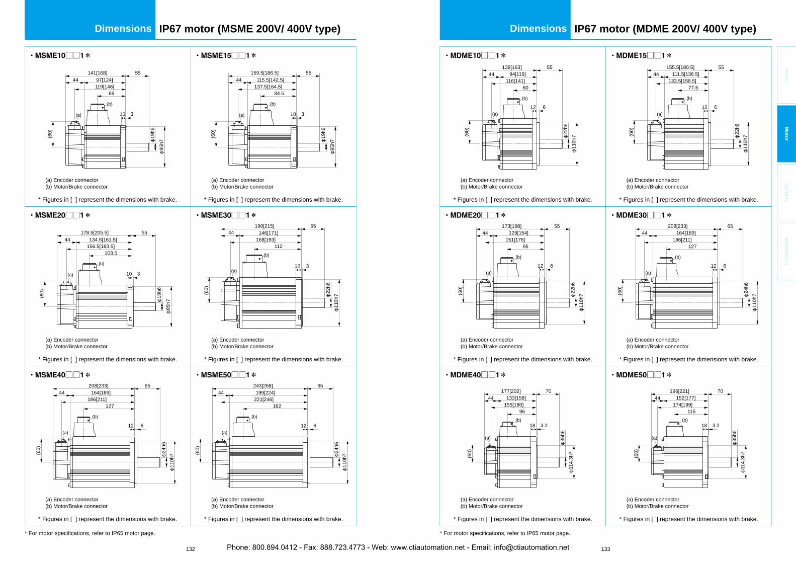
132 133
Driver
Mo
tor
Op
tion
sIn
form
ation
IP67 motor (MSME 200V/ 400V type)Dimensions Dimensions IP67 motor (MDME 200V/ 400V type)
* Figures in [ ] represent the dimensions with brake.
(a) Encoder connector(b) Motor/Brake connector
□□ *
* Figures in [ ] represent the dimensions with brake.
(a) Encoder connector(b) Motor/Brake connector
□□ *
* Figures in [ ] represent the dimensions with brake.
(a) Encoder connector(b) Motor/Brake connector
□□ *
* Figures in [ ] represent the dimensions with brake.
(a) Encoder connector(b) Motor/Brake connector
□□ *
* Figures in [ ] represent the dimensions with brake.
(a) Encoder connector(b) Motor/Brake connector
□□ *
* Figures in [ ] represent the dimensions with brake.
(a) Encoder connector(b) Motor/Brake connector
□□ *
* For motor specifications, refer to IP65 motor page.
141[168]97[124]44
55
10 3
(60)
19h6
119[146]66
95h7
(a)
(b)
159.5[186.5]115.5[142.5]44
55
10 3
(60)
19h6
137.5[164.5]84.5
(a)
(b)
95h7
178.5[205.5]134.5[161.5]44
55
10 3
(60)
19h6
156.5[183.5]103.5
(a)
(b)
95h7
44190[215] 55
12 3
(60)
110h
7
146[171]
22h6
168[193]112
(a)
(b)
44208[233] 65
12 6
(60)
110h
7
164[189]
24h6
186[211]127
(a)
(b)
44243[268] 65
12 6
(60)
110h
7
199[224]
24h6
221[246]162
(a)
(b)
* Figures in [ ] represent the dimensions with brake.
(a) Encoder connector(b) Motor/Brake connector
□□ *
* Figures in [ ] represent the dimensions with brake.
(a) Encoder connector(b) Motor/Brake connector
□□ *
* Figures in [ ] represent the dimensions with brake.
(a) Encoder connector(b) Motor/Brake connector
□□ *
* Figures in [ ] represent the dimensions with brake.
(a) Encoder connector(b) Motor/Brake connector
□□ *
* Figures in [ ] represent the dimensions with brake.
(a) Encoder connector(b) Motor/Brake connector
□□ *
* Figures in [ ] represent the dimensions with brake.
(a) Encoder connector(b) Motor/Brake connector
□□ *
* For motor specifications, refer to IP65 motor page.
44138[163] 55
12 6
94[119]
22h6
116[141]60
(a)
(b)
110h
7(60)
44155.5[180.5] 55
12 6
111.5[136.5]
22h6
133.5[158.5]77.5
(a)
(b)
110h
7(60)
44173[198] 55
12 6
(60)
129[154]
22h6
151[176]95
(a)
(b)
110h
7
44208[233] 65
12 6
164[189]
24h6
186[211]127
(a)
(b)
110h
7(60)
44177[202] 70
18 3.2
(60)
114.
3h7
133[158]
35h6
155[180]96
(a)
(b)
44196[221] 70
18 3.2
(60)
152[177]174[199]
115
(a)
(b)
114.
3h7
35h6
Phone: 800.894.0412 - Fax: 888.723.4773 - Web: www.ctiautomation.net - Email: [email protected]

134 135
Driver
Mo
tor
Op
tion
sIn
form
ation
IP67 motor (MHME 200V/ 400V type)DimensionsIP67 motor (MGME 200V/ 400V type)Dimensions
* Figures in [ ] represent the dimensions with brake.
(a) Encoder connector(b) Motor/Brake connector
□□1*
* Figures in [ ] represent the dimensions with brake.
(a) Encoder connector(b) Motor/Brake connector
□□1*
* Figures in [ ] represent the dimensions with brake.
(a) Encoder connector(b) Motor/Brake connector
□□1*
* For motor specifications, refer to IP65 motor page.
44155.5[180.5] 70
12 6
110h
7
111.5[136.5]
77.5133.5[158.5]
22h6
(a)
(b)
(60)
44163.5[188.5] 80
18 3.2
(60)
114.
3h7
119.5[144.5]
35h6
141.5[166.5]82.5
(a)
(b)
44209.5[234.5] 80
18 3.2
(60)
165.5[190.5]187.5[212.5]
128.5
(a)
(b)
114.
3h7
35h6
* Figures in [ ] represent the dimensions with brake.
(a) Encoder connector(b) Motor/Brake connector
□□ *
* Figures in [ ] represent the dimensions with brake.
(a) Encoder connector(b) Motor/Brake connector
□□ *
* Figures in [ ] represent the dimensions with brake.
(a) Encoder connector(b) Motor/Brake connector
□□ *
* Figures in [ ] represent the dimensions with brake.
(a) Encoder connector(b) Motor/Brake connector
□□ *
* Figures in [ ] represent the dimensions with brake.
(a) Encoder connector(b) Motor/Brake connector
□□ *
* Figures in [ ] represent the dimensions with brake.
(a) Encoder connector(b) Motor/Brake connector
□□ *
* For motor specifications, refer to IP65 motor page.
44173[198] 70
12 6
110h
7
129[154]
22h6
151[176]95
(a)
②
(60)
44190.5[215.5] 70
12 6
146.5[171.5]
22h6
168.5[193.5]112.5
(a)
②
110h
7(60)
4480
18 3.2
(60)
133[158]177[202]
155[180]96
(a)
②
114.
3h7
35h6
4480
18 3.2
(60)
152[177]196[221]
174[199]115
(a)
②
114.
3h7
35h6
4480
18 3.2
(60)
165.5[190.5]209.5[234.5]
187.5[212.5]128.5
(a)
②
114.
3h7
35h6
4480
18 3.2
(60)
194.5[219.5]238.5[263.5]
216.5[241.5]157.5
(a)
②
114.
3h7
35h6
Phone: 800.894.0412 - Fax: 888.723.4773 - Web: www.ctiautomation.net - Email: [email protected]
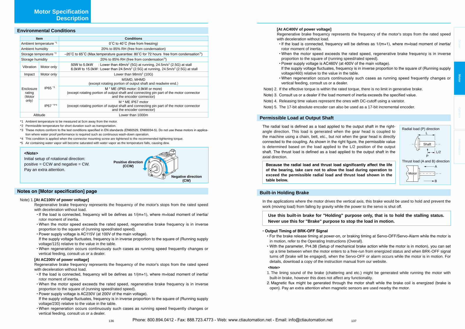
136 137
Driver
Mo
tor
Op
tion
sIn
form
ation
Motor Specification Description
Environmental Conditions
Item Conditions
Ambient temperature *1
Ambient humidity 20% to 85% RH (free from condensation)Storage temperature *2 *5)Storage humidity 20% to 85% RH (free from condensation*5)
Vibration Motor only2 (5G) at running, 24.5m/s2 (2.5G) at stall
2 (2.5G) at running, 24.5m/s2 (2.5G) at stallImpact Motor only Lower than 98m/s2 (10G)
Enclosurerating(Motoronly)
IP65 *3
MSMD, MHMD(except rotating portion of output shaft and readwire end.)
(except rotating portion of output shaft and connecting pin part of the motor connectorand the encoder connector)
IP67 *3*4M * ME IP67 motor
(except rotating portion of output shaft and connecting pin part of the motor connectorand the encoder connector)
Altitude Lower than 1000m *1 Ambient temperature to be measured at 5cm away from the motor.*2 Permissible temperature for short duration such as transportation.*3 -
tion where water proof performance is required such as continuous wash-down operation.*4 This condition is applied when the connector mounting screw are tightened to the recommended tightening torque.*5 Air containing water vapor will become saturated with water vapor as the temperature falls, causing dew.
<Note>Initial setup of rotational direction: positive = CCW and negative = CW.Pay an extra attention.
Positive direction(CCW)
Negative direction(CW)
Note) 1. [At AC100V of power voltage]Regenerative brake frequency represents the frequency of the motor's stops from the rated speed with deceleration without load.
rotor moment of inertia.
proportion to the square of (running speed/rated speed).
voltage/115) relative to the value in the table.
vertical feeding, consult us or a dealer. [At AC200V of power voltage]
Regenerative brake frequency represents the frequency of the motor's stops from the rated speed with deceleration without load.
rotor moment of inertia.
proportion to the square of (running speed/rated speed).
voltage/230) relative to the value in the table.
vertical feeding, consult us or a dealer.
[At AC400V of power voltage]Regenerative brake frequency represents the frequency of the motor's stops from the rated speed with deceleration without load.
rotor moment of inertia.
proportion to the square of (running speed/rated speed).
voltage/460) relative to the value in the table.
vertical feeding, consult us or a dealer.Note) 2. If the effective torque is within the rated torque, there is no limit in generative brake.
Note) 4. Releasing time values represent the ones with DC-cutoff using a varistor.Note) 5. The 17-bit absolute encoder can also be used as a 17-bit incremental encoder.
Permissible Load at Output Shaft
angle direction. This load is generated when the gear head is coupled to the machine using a chain, belt, etc., but not when the gear head is directly
is determined based on the load applied to the L/2 position of the output
axial direction.
of the bearing, take care not to allow the load during operation to exceed the permissible radial load and thrust load shown in the table below.
Built-in Holding Brake
In the applications where the motor drives the vertical axis, this brake would be used to hold and prevent the work (moving load) from falling by gravity while the power to the servo is shut off.
Use this built-in brake for "Holding" purpose only, that is to hold the stalling status. Never use this for "Brake" purpose to stop the load in motion.
in motion, refer to the Operating Instructions (Overall).
up a time between when the motor enters to a free-run from energized status and when BRK-OFF signal turns off (brake will be engaged), when the Servo-OFF or alarm occurs while the motor is in motion. For details, download a copy of the instruction manual from our website.
<Note>
1. The lining sound of the brake (chattering and etc.) might be generated while running the motor with built-in brake, however this does not affect any functionality.
open). Pay an extra attention when magnetic sensors are used nearby the motor.
A
B
Thrust load (A and B) direction
Radial load (P) directionL
L/2P
Shaft
Motor
Phone: 800.894.0412 - Fax: 888.723.4773 - Web: www.ctiautomation.net - Email: [email protected]
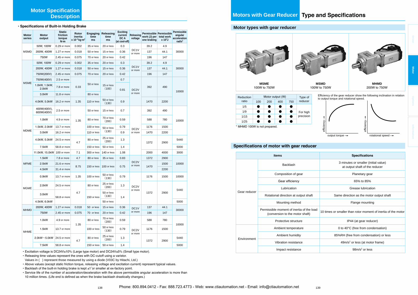
138 139
Driver
Mo
tor
Op
tion
sIn
form
ation
Motor Specification Description
Motorseries
Motoroutput
Staticfrictiontorque
N·m
Rotorinertia
x 10–4 kg·m2
Engagingtimems
Releasingtimems
ExcitingcurrentDC A
(at cool-off)
Releasingvoltage
Permissiblework (J) perone braking
Permissibletotal work
x 103J
Permissibleangular
accelerationrad/s2
MSMD
0.29 or more 0.002 35 or less 20 or less 0.3DC1Vor more
39.2 4.9
300001.27 or more 0.018 50 or less 15 or less 0.36 137 44.1
2.45 or more 0.075 70 or less 20 or less 0.42 196 147
MSME
0.29 or more 0.002 35 or less 20 or less 0.3DC1Vor more
39.2 4.9
300001.27 or more 0.018 50 or less 15 or less 0.36 137 44.1
2.45 or more 0.075 70 or less 20 or less 0.42 196 147
2.5 or more
0.3350 or less 15 or less
(100)
0.7
DC2Vor more
392 49010000
7.8 or more0.81
11.8 or more 80 or less
16.2 or more 1.35 110 or less 50 or less(130) 0.9 1470 2200
MDME
2.5 or more
1.35
50 or less 15 or less 0.7
DC2Vor more
392 490
100004.9 or more 80 or less 70 or less(200) 0.59 588 780
13.7 or more 100 or less 50 or less(130)
0.79 1176 1500
16.2 or more 110 or less 0.9 1470 2200
24.5 or more4.7
80 or less 25 or less(200) 1.3
1372 29005440
58.8 or more 150 or less 50 or less 1.4 5000
100 or more 7.1 300 or less 140 or less 1.08 2000 4000 3000
MFME
7.8 or more 4.7 80 or less 35 or less 0.83DC2Vor more
1372 2900
1000021.6 or more8.75 150 or less 100 or less 0.75 1470
1500
31.4 or more 2200
MGME
13.7 or more 1.35 100 or less 50 or less(130) 0.79
DC2Vor more
1176 1500 10000
24.5 or more
4.7
80 or less 25 or less(200) 1.3
1372 29005440
58.8 or more 150 or less50 or less(130) 1.450 or less 5000
MHMD1.27 or more 0.018 50 or less 15 or less 0.36 DC1V
or more
137 44.130000
2.45 or more 0.075 70 or less 20 or less 0.42 196 147
MHME
4.9 or more
1.3580 or less 70 or less
(200) 0.59
DC2Vor more
588 78010000
13.7 or more 100 or less 50 or less(130) 0.79 1176 1500
~ 24.5 or more4.7
80 or less 25 or less(200) 1.3
1372 29005440
58.8 or more 150 or less 50 or less 1.4 5000
Values in ( ) represent those measured by using a diode (V03C by Hitachi, Ltd.)
Motors with Gear Reducer
Motor types with gear reducer
MSME MSMD MHMD
Reductionratio
Type of reducer100 200 400 750
1/5 ● ● ● ●
For high precision
1/9 ● ● ● ●1/15 ● ● ● ●1/25 ● ● ● ●
Items
Gear reducer
Backlash 3 minutes or smaller (initial value) at output shaft of the reducer
Composition of gear Planetary gear
65% to 85%
Lubrication Grease lubrication
Rotational direction at output shaft Same direction as the motor output shaft
Mounting method Flange mounting
Permissible moment of inertia of the load (conversion to the motor shaft) 10 times or smaller than rotor moment of inertia of the motor
Protective structure IP44 (at gear reducer)
Environment
Ambient temperature 0 to 40°C (free from condensation)
Ambient humidity 85%RH (free from condensation) or less
Vibration resistance 49m/s2 or less (at motor frame)
Impact resistance 98m/s2 or less
Efficiency of the gear reducer show the following inclination in relation to output torque and rotational speed.
output torque rotational speed
effic
ienc
y
effic
ienc
y
Phone: 800.894.0412 - Fax: 888.723.4773 - Web: www.ctiautomation.net - Email: [email protected]
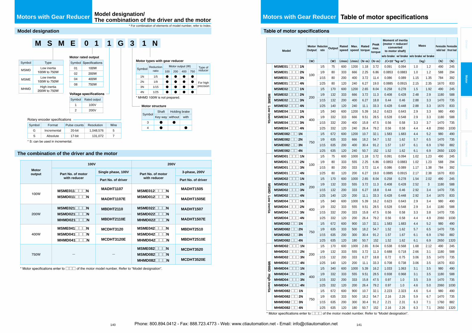
140 141
Driver
Mo
tor
Op
tion
sIn
form
ation
Motors with Gear Reducer
Model designation
The combination of the driver and the motor
Motoroutput
100V 200V
Part No. of motorwith reducer
Single phase, 100V Part No. of motorwith reducer
3-phase, 200V
Part No. of driver Part No. of driver
MSME011□□□N
MSMD011□□□N
MADHT1107 MSME012□□□N
MSMD012□□□N
MADHT1505
MADHT1107E MADHT1505E
MSME021□□□N
MSMD021□□□N
MHMD021□□□N
MBDHT2110 MSME022□□□N
MSMD022□□□N
MHMD022□□□N
MADHT1507
MBDHT2110E MADHT1507E
MSME041□□□N
MSMD041□□□N
MHMD041□□□N
MCDHT3120 MSME042□□□N
MSMD042□□□N
MHMD042□□□N
MBDHT2510
MCDHT3120E MBDHT2510E
- -MSME082□□□N
MSMD082□□□N
MHMD082□□□N
MCDHT3520
MCDHT3520E
□□□ of the motor model number. Refer to “Model designation”.
Symbol Rated output1 100V2 200V
Motor types with gear reducer
Symbol Reductionratio
Type of reducer100 200 400 750
1N 1/5 ● ● ● ●
For high precision
2N 1/9 ● ● ● ●
3N 1/15 ● ● ● ●
4N 1/25 ● ● ● ●
Motor structure
SymbolShaft Holding brake
Key way without with3 ● ●4 ● ●
Symbol Format Pulse counts ResolutionG Incremental 20-bit 1,048,576 5S Absolute 17-bit 131,072 7
M S M E 0 1 1 G 3 1 N
Motor rated output
Symbol01020408
Symbol Type
MSMD Low inertia
MSME Low inertia
MHMD High inertia
Model designation/The combination of the driver and the motor Motors with Gear Reducer
Model
MotorOutput
Reductionratio
OutputRatedspeed
Max.speed
Ratedtorque
Peakmax.
torque
Moment of inertia (motor + reducer/
convertedto motor shaft)
Mass Permissibleradial load
Permissiblethrust load
w/o brake w/ brake w/o brake w/ brake
(W) (W)(r/min)(r/min)(N・m)(N・m) J(×10-4kg・m2) (kg) (N) (N)
MS
ME
Lo
w in
ertia
MSME01□□□ 1N
100
1/5 75 600 1200 1.18 3.72 0.091 0.094 1.0 1.2 490 245MSME01□□□ 2N 1/9 80 333 666 2.25 6.86 0.0853 0.0883 1.0 1.2 588 294MSME01□□□ 3N 1/15 80 200 400 3.72 11.4 0.086 0.089 1.15 1.35 784 392MSME01□□□ 4N 1/25 80 120 240 6.27 19.0 0.0885 0.0915 2.15 2.35 1670 833MSME02□□□ 1N
200
1/5 170 600 1200 2.65 8.04 0.258 0.278 1.5 1.92 490 245MSME02□□□ 2N 1/9 132 333 666 3.72 11.3 0.408 0.428 2.48 2.9 1180 588MSME02□□□ 3N 1/15 132 200 400 6.27 18.8 0.44 0.46 2.88 3.3 1470 735MSME02□□□ 4N 1/25 140 120 240 11.1 33.3 0.428 0.448 2.88 3.3 1670 833MSME04□□□ 1N
400
1/5 340 600 1200 5.39 16.2 0.623 0.643 2.9 3.3 980 490MSME04□□□ 2N 1/9 332 333 666 9.51 28.5 0.528 0.548 2.9 3.3 1180 588MSME04□□□ 3N 1/15 332 200 400 15.8 47.5 0.56 0.58 3.3 3.7 1470 735MSME04□□□ 4N 1/25 332 120 240 26.4 79.2 0.56 0.58 4.4 4.8 2060 1030MSME082□□ 1N
750
1/5 672 600 1200 10.7 32.1 1.583 1.683 4.4 5.2 980 490MSME082□□ 2N 1/9 635 333 666 18.2 54.7 1.52 1.62 5.7 6.5 1470 735MSME082□□ 3N 1/15 635 200 400 30.4 91.2 1.57 1.67 6.1 6.9 1760 882MSME082□□ 4N 1/25 635 120 240 50.7 152 1.52 1.62 6.1 6.9 2650 1320
MS
MD
Lo
w in
ertia
MSMD01□□□ 1N
100
1/5 75 600 1000 1.18 3.72 0.091 0.094 1.02 1.23 490 245MSMD01□□□ 2N 1/9 80 333 555 2.25 6.86 0.0853 0.0883 1.02 1.23 588 294MSMD01□□□ 3N 1/15 80 200 333 3.72 11.4 0.086 0.089 1.17 1.38 784 392MSMD01□□□ 4N 1/25 80 120 200 6.27 19.0 0.0885 0.0915 2.17 2.38 1670 833MSMD02□□□ 1N
200
1/5 170 600 1000 2.65 8.04 0.258 0.278 1.54 2.02 490 245MSMD02□□□ 2N 1/9 132 333 555 3.72 11.3 0.408 0.428 2.52 3 1180 588MSMD02□□□ 3N 1/15 132 200 333 6.27 18.8 0.44 0.46 2.92 3.4 1470 735MSMD02□□□ 4N 1/25 140 120 200 11.1 33.3 0.428 0.448 2.92 3.4 1670 833MSMD04□□□ 1N
400
1/5 340 600 1000 5.39 16.2 0.623 0.643 2.9 3.4 980 490MSMD04□□□ 2N 1/9 332 333 555 9.51 28.5 0.528 0.548 2.9 3.4 1180 588MSMD04□□□ 3N 1/15 332 200 333 15.8 47.5 0.56 0.58 3.3 3.8 1470 735MSMD04□□□ 4N 1/25 332 120 200 26.4 79.2 0.56 0.58 4.4 4.9 2060 1030MSMD082□□ 1N
750
1/5 672 600 900 10.7 32.1 1.583 1.683 4.4 5.2 980 490MSMD082□□ 2N 1/9 635 333 500 18.2 54.7 1.52 1.62 5.7 6.5 1470 735MSMD082□□ 3N 1/15 635 200 300 30.4 91.2 1.57 1.67 6.1 6.9 1760 882MSMD082□□ 4N 1/25 635 120 180 50.7 152 1.52 1.62 6.1 6.9 2650 1320
MH
MD
Hig
h in
ertia
MHMD02□□□ 1N
200
1/5 170 600 1000 2.65 8.04 0.538 0.568 1.68 2.12 490 245MHMD02□□□ 2N 1/9 132 333 555 3.72 11.3 0.688 0.718 2.66 3.1 1180 588MHMD02□□□ 3N 1/15 132 200 333 6.27 18.8 0.72 0.75 3.06 3.5 1470 735MHMD02□□□ 4N 1/25 140 120 200 11.1 33.3 0.708 0.738 3.06 3.5 1670 833MHMD04□□□ 1N
400
1/5 340 600 1000 5.39 16.2 1.033 1.063 3.1 3.5 980 490MHMD04□□□ 2N 1/9 332 333 555 9.51 28.5 0.938 0.968 3.1 3.5 1180 588MHMD04□□□ 3N 1/15 332 200 333 15.8 47.5 0.97 1.0 3.5 3.9 1470 735MHMD04□□□ 4N 1/25 332 120 200 26.4 79.2 0.97 1.0 4.6 5.0 2060 1030MHMD082□□ 1N
750
1/5 672 600 900 10.7 32.1 2.223 2.323 4.6 5.4 980 490MHMD082□□ 2N 1/9 635 333 500 18.2 54.7 2.16 2.26 5.9 6.7 1470 735MHMD082□□ 3N 1/15 635 200 300 30.4 91.2 2.21 2.31 6.3 7.1 1760 882MHMD082□□ 4N 1/25 635 120 180 50.7 152 2.16 2.26 6.3 7.1 2650 1320
□□□ of the motor model number. Refer to “Model designation”.
* For combination of elements of model number, refer to Index.
Phone: 800.894.0412 - Fax: 888.723.4773 - Web: www.ctiautomation.net - Email: [email protected]
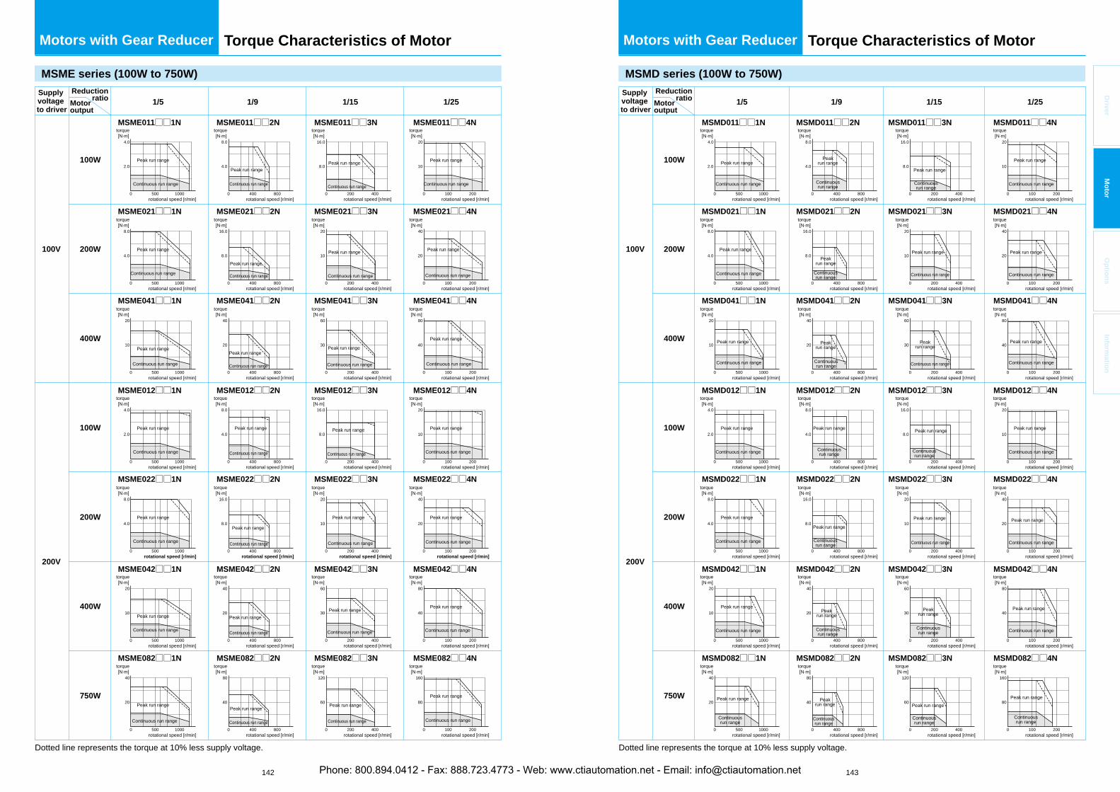
142 143
Driver
Mo
tor
Op
tion
sIn
form
ation
Motors with Gear Reducer
MSME series (100W to 750W)
Supplyvoltageto driver
Reductionratio 1/5
MSME011□□1N MSME011□□2N MSME011□□3N
MSME021□□1N MSME021□□2N MSME021□□3N
MSME041□□1N MSME041□□2N MSME041□□3N
MSME012□□1N MSME012□□2N MSME012□□3N
MSME022□□1N MSME022□□2N MSME022□□3N
MSME042□□1N MSME042□□2N MSME042□□3N
MSME082□□1N MSME082□□2N MSME082□□3N
1/9 1/251/15
100W
100V
200V
100W
200W
200W
400W
750W
400W
Dotted line represents the torque at 10% less supply voltage.
Motoroutput
MSME011□□4N
MSME021□□4N
MSME041□□4N
MSME012□□4N
MSME022□□4N
MSME042□□4N
MSME082□□4N
0 500 1000
4.0
2.0
0 400 800
8.0
4.0
0 200 400
16.0
8.0
0 100 200
20
10
0 500 1000
4.0
2.0
0 400 800
8.0
4.0
0 200 400
16.0
8.0
0 100 200
20
10
0 500 1000
8.0
4.0
0 400 800
16.0
8.0
0 200 400
20
10
0 100 200
40
20
0 500 1000
8.0
4.0
0 400 800
16.0
8.0
0 200 400
20
10
0 100 200
40
20
0 500 1000
20
10
0 400 800
40
20
0 200 400
60
30
0 100 200
80
40
0 500 1000
20
10
0 400 800
40
20
0 200 400
60
30
0 100 200
80
40
0 500 1000
40
20
0 400 800
80
40
0 200 400
120
60
0 100 200
160
80
rotational speed [r/min]
torque[N.m]
Peak run range
Continuous run range
rotational speed [r/min]
torque[N.m]
Peak run range
Continuous run range
rotational speed [r/min]
torque[N.m]
Peak run range
Continuous run range
rotational speed [r/min]
torque[N.m]
Peak run range
Continuous run range
rotational speed [r/min]
torque[N.m]
Peak run range
Continuous run range
rotational speed [r/min]
torque[N.m]
Peak run range
Continuous run range
rotational speed [r/min]
torque[N.m]
Peak run range
Continuous run range
rotational speed [r/min]
torque[N.m]
Peak run range
Continuous run range
rotational speed [r/min]
torque[N.m]
Peak run range
Continuous run range
rotational speed [r/min]
torque[N.m]
Peak run range
Continuous run range
rotational speed [r/min]
torque[N.m]
Peak run range
Continuous run range
rotational speed [r/min]
torque[N.m]
Peak run range
Continuous run range
rotational speed [r/min]
torque[N.m]
Peak run range
Continuous run range
rotational speed [r/min]
torque[N.m]
Peak run range
Continuous run range
rotational speed [r/min]
torque[N.m]
Peak run range
Continuous run range
rotational speed [r/min]
torque[N.m]
Peak run range
Continuous run range
rotational speed [r/min]
torque[N.m]
Peak run range
Continuous run range
rotational speed [r/min]
torque[N.m]
Peak run range
Continuous run range
rotational speed [r/min]
torque[N.m]
Peak run range
Continuous run range
rotational speed [r/min]
torque[N.m]
Peak run range
Continuous run range
rotational speed [r/min]
torque[N.m]
Peak run range
Continuous run range
rotational speed [r/min]
torque[N.m]
Peak run range
Continuous run range
rotational speed [r/min]
torque[N.m]
Peak run range
Continuous run range
rotational speed [r/min]
torque[N.m]
Peak run range
Continuous run range
rotational speed [r/min]
torque[N.m]
Peak run range
Continuous run range
rotational speed [r/min]
torque[N.m]
Peak run range
Continuous run range
rotational speed [r/min]
torque[N.m]
Peak run range
Continuous run range
rotational speed [r/min]
torque[N.m]
Peak run range
Continuous run range
Torque Characteristics of Motor Motors with Gear Reducer Torque Characteristics of Motor
MSMD series (100W to 750W)
1/5
MSMD011□□1N MSMD011□□2N MSMD011□□3N MSMD011□□4N
MSMD021□□1N MSMD021□□2N MSMD021□□3N MSMD021□□4N
MSMD041□□1N MSMD041□□2N MSMD041□□3N MSMD041□□4N
MSMD012□□1N MSMD012□□2N MSMD012□□3N MSMD012□□4N
MSMD022□□1N MSMD022□□2N MSMD022□□3N MSMD022□□4N
MSMD042□□1N MSMD042□□2N MSMD042□□3N MSMD042□□4N
MSMD082□□1N MSMD082□□2N MSMD082□□3N MSMD082□□4N
1/9 1/251/15
100W
100V
200V
100W
200W
200W
400W
750W
400W
Dotted line represents the torque at 10% less supply voltage.
Supplyvoltageto driver
Reductionratio
Motoroutput
0 500 1000
4.0
2.0
0 400 800
8.0
4.0
0 200 400
16.0
8.0
0 100 200
20
10
0 500 1000
8.0
4.0
0 400 800
16.0
8.0
0 200 400
20
10
0 100 200
40
20
0 500 1000
20
10
0 400 800
40
20
0 200 400
60
30
0 100 200
80
40
0 500 1000
4.0
2.0
0 400 800
8.0
4.0
0 200 400
16.0
8.0
0 100 200
20
10
0 500 1000
8.0
4.0
0 400 800
16.0
8.0
0 200 400
20
10
0 100 200
40
20
0 500 1000
20
10
0 400 800
40
20
0 200 400
60
30
0 100 200
80
40
0 500 1000
40
20
0 400 800
80
40
0 200 400
120
60
0 100 200
160
80
rotational speed [r/min]
torque[N.m]
Peak run range
Continuous run range
rotational speed [r/min]
torque[N.m]
Peak run range
Continuous run range
rotational speed [r/min]
torque[N.m]
Peak run range
Continuous run range
rotational speed [r/min]
torque[N.m]
Peak run range
Continuous run range
rotational speed [r/min]
torque[N.m]
Peak run range
Continuous run range
rotational speed [r/min]
torque[N.m]
Peak run range
Continuous run range
rotational speed [r/min]
torque[N.m]
Peak run range
Continuousrun range
rotational speed [r/min]
torque[N.m]
Peakrun range
Continuousrun range
rotational speed [r/min]
torque[N.m]
Peakrun range
Continuousrun range
rotational speed [r/min]
torque[N.m]
Peakrun range
Continuousrun range
rotational speed [r/min]
torque[N.m]
Peak run range
Continuousrun range
rotational speed [r/min]
torque[N.m]
Peak run range
Continuousrun range
rotational speed [r/min]
torque[N.m]
Peakrun range
Continuousrun range
rotational speed [r/min]
torque[N.m]
Peakrun range
Continuousrun range
rotational speed [r/min]
torque[N.m]
Peak run range
Continuousrun range
rotational speed [r/min]
torque[N.m]
Peak run range
Continuous run range
rotational speed [r/min]
torque[N.m]
Peakrun range
Continuous run range
rotational speed [r/min]
torque[N.m]
Peak run range
Continuousrun range
rotational speed [r/min]
torque[N.m]
Peak run range
Continuous run range
rotational speed [r/min]
torque[N.m]
Peakrun range
Continuousrun range
rotational speed [r/min]
torque[N.m]
rotational speed [r/min]
torque[N.m]
Peak run range
Continuous run range
rotational speed [r/min]
torque[N.m]
Peak run range
Continuous run range
rotational speed [r/min]
torque[N.m]
Peak run range
Continuous run range
rotational speed [r/min]
torque[N.m]
Peak run range
Continuous run range
rotational speed [r/min]
torque[N.m]
Peak run range
Continuous run range
rotational speed [r/min]
torque[N.m]
Peak run range
Continuous run range
rotational speed [r/min]
torque[N.m]
Peak run range
Continuousrun range
Peak run range
Continuousrun range
Phone: 800.894.0412 - Fax: 888.723.4773 - Web: www.ctiautomation.net - Email: [email protected]
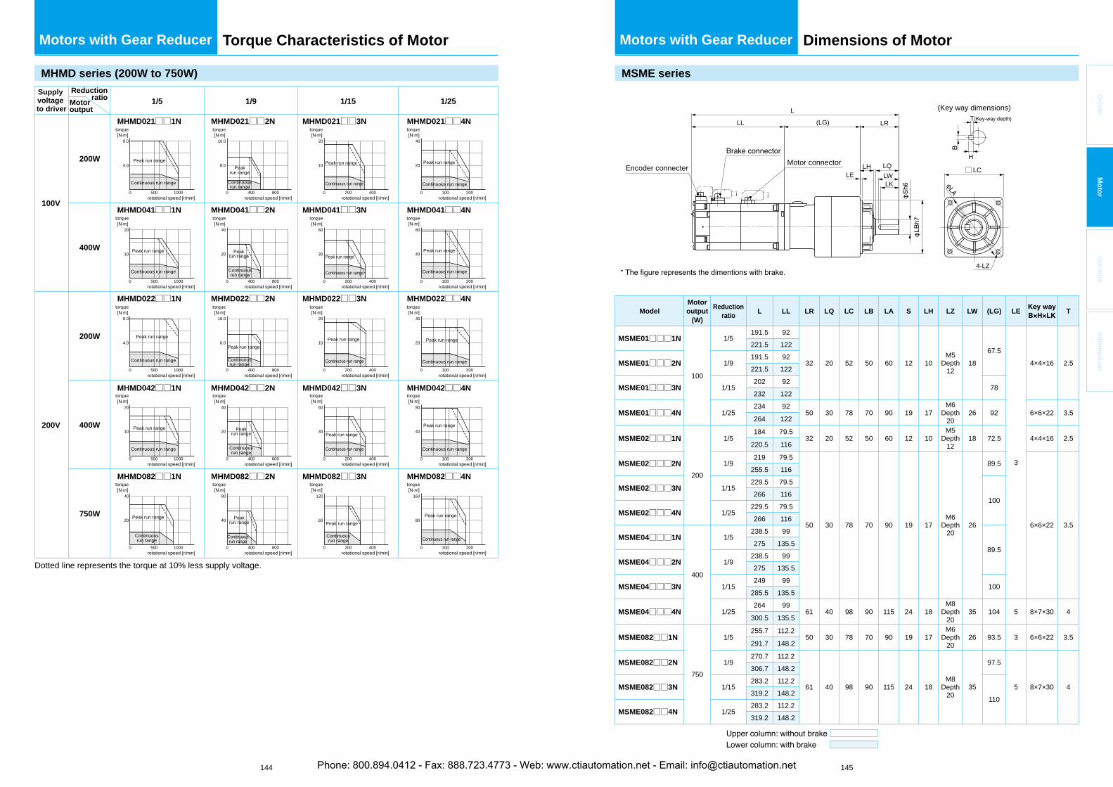
144 145
Driver
Mo
tor
Op
tion
sIn
form
ation
Motors with Gear Reducer Torque Characteristics of Motor
MHMD series (200W to 750W)
1/5
MHMD021□□1N MHMD021□□2N MHMD021□□3N MHMD021□□4N
MHMD041□□1N MHMD041□□2N MHMD041□□3N MHMD041□□4N
MHMD022□□1N MHMD022□□2N MHMD022□□3N MHMD022□□4N
MHMD042□□1N MHMD042□□2N MHMD042□□3N MHMD042□□4N
MHMD082□□1N MHMD082□□2N MHMD082□□3N MHMD082□□4N
1/9 1/251/15
100V
200V
200W
200W
400W
750W
400W
Dotted line represents the torque at 10% less supply voltage.
Supplyvoltageto driver
Reductionratio
Motoroutput
0 500 1000
8.0
4.0
0 400 800
16.0
8.0
0 200 400
20
10
0 100 200
40
20
0 500 1000
8.0
4.0
0 400 800
16.0
8.0
0 200 400
20
10
0 100 200
40
20
0 500 1000
20
10
0 400 800
40
20
0 200 400
60
30
0 100 200
80
40
0 500 1000
20
10
0 400 800
40
20
0 200 400
60
30
0 100 200
80
40
0 500 1000
40
20
0 400 800
80
40
0 200 400
120
60
0 100 200
160
80
rotational speed [r/min]
torque[N.m]
Peak run range
Continuous run range
rotational speed [r/min]
torque[N.m]
Peak run range
Continuous run range
rotational speed [r/min]
torque[N.m]
Peak run range
Continuous run range
rotational speed [r/min]
torque[N.m]
Peak run range
Continuous run range
rotational speed [r/min]
torque[N.m]
Peak run range
Continuousrun range
rotational speed [r/min]
torque[N.m]
Peakrun range
Continuousrun range
rotational speed [r/min]
torque[N.m]
Peakrun range
Continuousrun range
rotational speed [r/min]
torque[N.m]
Peak run range
Continuousrun range
rotational speed [r/min]
torque[N.m]
Peakrun range
Continuousrun range
rotational speed [r/min]
torque[N.m]
Peakrun range
Continuousrun range
rotational speed [r/min]
torque[N.m]
Peak run range
Continuous run range
rotational speed [r/min]
torque[N.m]
Peak run range
Continuous run range
rotational speed [r/min]
torque[N.m]
Peak run range
Continuous run range
rotational speed [r/min]
torque[N.m]
Peak run range
Continuous run range
rotational speed [r/min]
torque[N.m]
Peak run range
Continuous run range
Dimensions of Motor
MSME series
(LG)
LWLK
L
LL LR
LQLE
LH LC
4-LZ
H
T( )
(Key way dimensions)
Encoder connecterMotor connector
□
ModelMotoroutput
(W)
Reductionratio
L LL LR LQ LC LB LA S LH LZ LW (LG) LE T
MSME01□□□1N
100
1/5191.5 92
32 20 52 50 60 12 10M5
Depth12
1867.5
3
4×4×16 2.5
221.5 122
MSME01□□□2N 1/9191.5 92221.5 122
MSME01□□□3N 1/15202 92
78232 122
MSME01□□□4N 1/25234 92
50 30 78 70 90 19 17M6
Depth20
26 92 6×6×22 3.5264 122
MSME02□□□1N
200
1/5184 79.5
32 20 52 50 60 12 10M5
Depth12
18 72.5 4×4×16 2.5220.5 116
MSME02□□□2N 1/9219 79.5
50 30 78 70 90 19 17M6
Depth20
26
89.5
6×6×22 3.5
255.5 116
MSME02□□□3N 1/15229.5 79.5
100266 116
MSME02□□□4N 1/25229.5 79.5266 116
MSME04□□□1N
400
1/5238.5 99
89.5275 135.5
MSME04□□□2N 1/9238.5 99275 135.5
MSME04□□□3N 1/15249 99
100285.5 135.5
MSME04□□□4N 1/25264 99
61 40 98 90 115 24 18M8
Depth20
35 104 5 8×7×30 4300.5 135.5
MSME082□□1N
750
1/5255.7 112.2
50 30 78 70 90 19 17M6
Depth20
26 93.5 3 6×6×22 3.5291.7 148.2
MSME082□□2N 1/9270.7 112.2
61 40 98 90 115 24 18M8
Depth20
35
97.5
5 8×7×30 4
306.7 148.2
MSME082□□3N 1/15283.2 112.2
110319.2 148.2
MSME082□□4N 1/25283.2 112.2319.2 148.2
Motors with Gear Reducer
Phone: 800.894.0412 - Fax: 888.723.4773 - Web: www.ctiautomation.net - Email: [email protected]
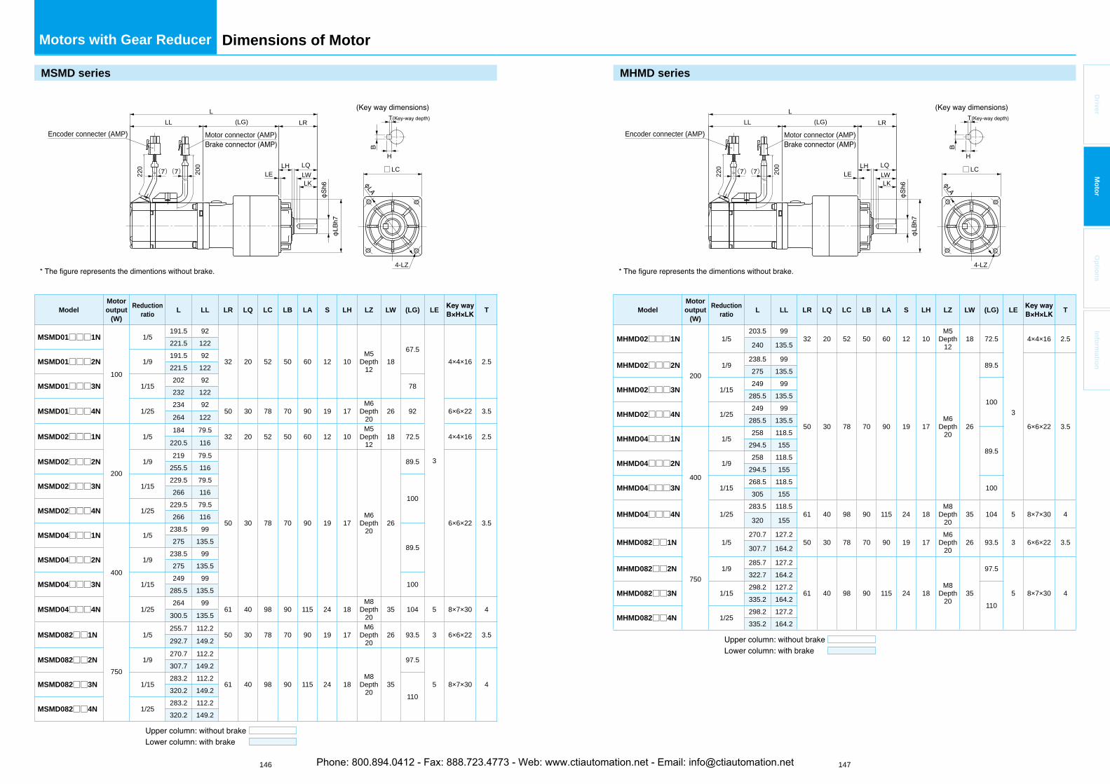
146 147
Driver
Mo
tor
Op
tion
sIn
form
ation
Dimensions of Motor
MSMD series
(LG)
LWLK
LLL LR
LQLE
LH
220
Encoder connecter (AMP) Motor connector (AMP)
200 □LC
4-LZ
( )( )
H
T( )
ModelMotoroutput
(W)
Reductionratio
L LL LR LQ LC LB LA S LH LZ LW (LG) LE T
MSMD01□□□1N
100
1/5191.5 92
32 20 52 50 60 12 10M5
Depth12
1867.5
3
4×4×16 2.5
221.5 122
MSMD01□□□2N 1/9191.5 92221.5 122
MSMD01□□□3N 1/15202 92
78232 122
MSMD01□□□4N 1/25234 92
50 30 78 70 90 19 17M6
Depth20
26 92 6×6×22 3.5264 122
MSMD02□□□1N
200
1/5184 79.5
32 20 52 50 60 12 10M5
Depth12
18 72.5 4×4×16 2.5220.5 116
MSMD02□□□2N 1/9219 79.5
50 30 78 70 90 19 17M6
Depth20
26
89.5
6×6×22 3.5
255.5 116
MSMD02□□□3N 1/15229.5 79.5
100266 116
MSMD02□□□4N 1/25229.5 79.5266 116
MSMD04□□□1N
400
1/5238.5 99
89.5275 135.5
MSMD04□□□2N 1/9238.5 99275 135.5
MSMD04□□□3N 1/15249 99
100285.5 135.5
MSMD04□□□4N 1/25264 99
61 40 98 90 115 24 18M8
Depth20
35 104 5 8×7×30 4300.5 135.5
MSMD082□□1N
750
1/5255.7 112.2
50 30 78 70 90 19 17M6
Depth20
26 93.5 3 6×6×22 3.5292.7 149.2
MSMD082□□2N 1/9270.7 112.2
61 40 98 90 115 24 18M8
Depth20
35
97.5
5 8×7×30 4
307.7 149.2
MSMD082□□3N 1/15283.2 112.2
110320.2 149.2
MSMD082□□4N 1/25283.2 112.2320.2 149.2
Motors with Gear Reducer
MHMD series
(LG)
LWLK
LLL LR
LQLE
LH
220
Encoder connecter (AMP) Motor connector (AMP)
200 □LC( )( )
4-LZ
H
T( )
ModelMotoroutput
(W)
Reductionratio
L LL LR LQ LC LB LA S LH LZ LW (LG) LE T
MHMD02□□□1N
200
1/5203.5 99
32 20 52 50 60 12 10M5
Depth12
18 72.5
3
4×4×16 2.5240 135.5
MHMD02□□□2N 1/9238.5 99
50 30 78 70 90 19 17M6
Depth20
26
89.5
6×6×22 3.5
275 135.5
MHMD02□□□3N 1/15249 99
100285.5 135.5
MHMD02□□□4N 1/25249 99
285.5 135.5
MHMD04□□□1N
400
1/5258 118.5
89.5294.5 155
MHMD04□□□2N 1/9258 118.5
294.5 155
MHMD04□□□3N 1/15268.5 118.5
100305 155
MHMD04□□□4N 1/25283.5 118.5
61 40 98 90 115 24 18M8
Depth20
35 104 5 8×7×30 4320 155
MHMD082□□1N
750
1/5270.7 127.2
50 30 78 70 90 19 17M6
Depth20
26 93.5 3 6×6×22 3.5307.7 164.2
MHMD082□□2N 1/9285.7 127.2
61 40 98 90 115 24 18M8
Depth20
35
97.5
5 8×7×30 4
322.7 164.2
MHMD082□□3N 1/15298.2 127.2
110335.2 164.2
MHMD082□□4N 1/25298.2 127.2335.2 164.2
Phone: 800.894.0412 - Fax: 888.723.4773 - Web: www.ctiautomation.net - Email: [email protected]
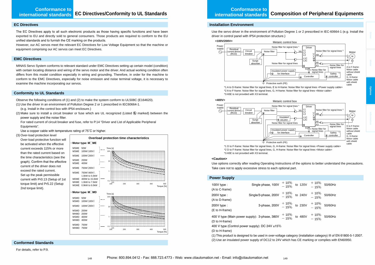
148 149
Driver
Mo
tor
Op
tion
sIn
form
ation
Composition of Peripheral Equipments
Installation Environment
Use the servo driver in the environment of Pollution Degree 1 or 2 prescribed in IEC-60664-1 (e.g. Install the driver in control panel with IP54 protection structure.)
Metaric control box<100V/200V>
Controller
Insulated power supply for interface Safety
controller
Powersupply Residual
current device(RCD)
Surgeabsorber
Surgeabsorber
Noise filter
Noise filter for signal linesNoise filter for signal lines
Noise filter for signal lines
Noise filter for signal lines *1
Protective earth (PE)
L1U
X4
XAXB
X3X6
M
RE
VW
L2L3L1CL2C
Driver
MotorCircuitbreaker
Noise filter for signal lines *2
*1 A to D-frame: Noise filter for signal lines, E to H-frame: Noise filter for signal lines <Power supply cable>*2 A to F-frame: Noise filter for signal lines, G, H-frame: Noise filter for signal lines <Motor cable>*3 A5E is not provided with X3 terminal.
A to F-frame:Motor cablewithout shieldcableG, H-frame:Motor cablewith shieldcable
*3
<400V>
*1 D to F-frame: Noise filter for signal lines, G, H-frame: Noise filter for signal lines <Power supply cable>*2 D to F-frame: Noise filter for signal lines, G, H-frame: Noise filter for signal lines <Motor cable>*3 A5E is not provided with X3 terminal.
Metaric control box
Controller
Insulated power supply for interface Safety
controller
Powersupply Residual
current device(RCD)
InsulatedDC24V
Noise filter
Noise filter for signal lines Noise filter for signal lines
Noise filter for signal lines
Noise filter for signal lines *1
Protective earth (PE)
L1U
X4
XAXB
X3X6
M
RE
VW
L2L3L1CL2C
Driver
MotorCircuitbreaker
Noise filter for signal lines *2
D to F-frame:Motor cablewithout shieldcableG, H-frame:Motor cablewith shieldcable
*3
<Caution>
Use options correctly after reading Operating Instructions of the options to better understand the precautions. Take care not to apply excessive stress to each optional part.
Power Supply+ 10% to 120V + 10% 50/60Hz
(A to C-frame)- 15% - 15%
+ 10% to 240V + 10% 50/60Hz(A to D-frame)
- 15% - 15%
+ 10% to 230V + 10% 50/60Hz(E to H-frame)
- 15% - 15%
+ 10% to 480V + 10% 50/60Hz(D to H-frame)
- 15% - 15%
%(D to H-frame)(1)(2) Use an insulated power supply of DC12 to 24V which has CE marking or complies with EN60950.
Conformance tointernational standards
EC Directives
exported to EU and directly sold to general consumers. Those products are required to conform to the EU
However, our AC servos meet the relevant EC Directives for Low Voltage Equipment so that the machine or equipment comprising our AC servos can meet EC Directives.
EMC Directives
MINAS Servo System conforms to relevant standard under EMC Directives setting up certain model (condition) with certain locating distance and wiring of the servo motor and the driver. And actual working condition often differs from this model condition especially in wiring and grounding. Therefore, in order for the machine to conform to the EMC Directives, especially for noise emission and noise terminal voltage, it is necessary to examine the machine incorporating our servos.
Conformity to UL Standards
Observe the following conditions of (1) and (2) to make the system conform to UL508C (E164620).(1) Use the driver in an environment of Pollution Degree 2 or 1 prescribed in IEC60664-1.
(e.g. Install in the control box with IP54 enclosure.)(2) Make sure to install a circuit breaker or fuse which are UL recognized (Listed marked) between the
For rated current of circuit breaker and fuse, refer to P.14 “Driver and List of Applicable Peripheral Equipments”.
(3) Over-load protection levelOver-load protective function will be activated when the effective current exceeds 115% or more than the rated current based on the time characteristics (see the
current of the driver does not exceed the rated current.Set up the peak permissible current with Pr0.13 (Setup of 1st torque limit) and Pr5.22 (Setup 2nd torque limit).
Conformed Standards
For details, refer to P.9.
Time [s]
Overload protection time characteristics
MSME 50WMSME 100W(100V)
MSME 100W(200V)
MSME 200WMSME 400W
MSME 750W(200V)
MSME 750W(400V), 1.0kW to 5.0kWMDME 400W to 15.0kWMHME 1.0kW to 7.5kWMGME 0.9kW to 6.0kW
100115
0.1
1
10
100
200 300 400 500Torque [%]
Time [s]
100115
0.1
1
10
100
200 300 400 500Torque [%]
□
□
MSMD 50WMSMD 100W(100V)
MSMD 100W(200V)
MSMD 200WMHMD 200WMSMD 400WMHMD 400W
MSMD 750WMHMD 750W
Conformance tointernational standards EC Directives/Conformity to UL Standards
Phone: 800.894.0412 - Fax: 888.723.4773 - Web: www.ctiautomation.net - Email: [email protected]
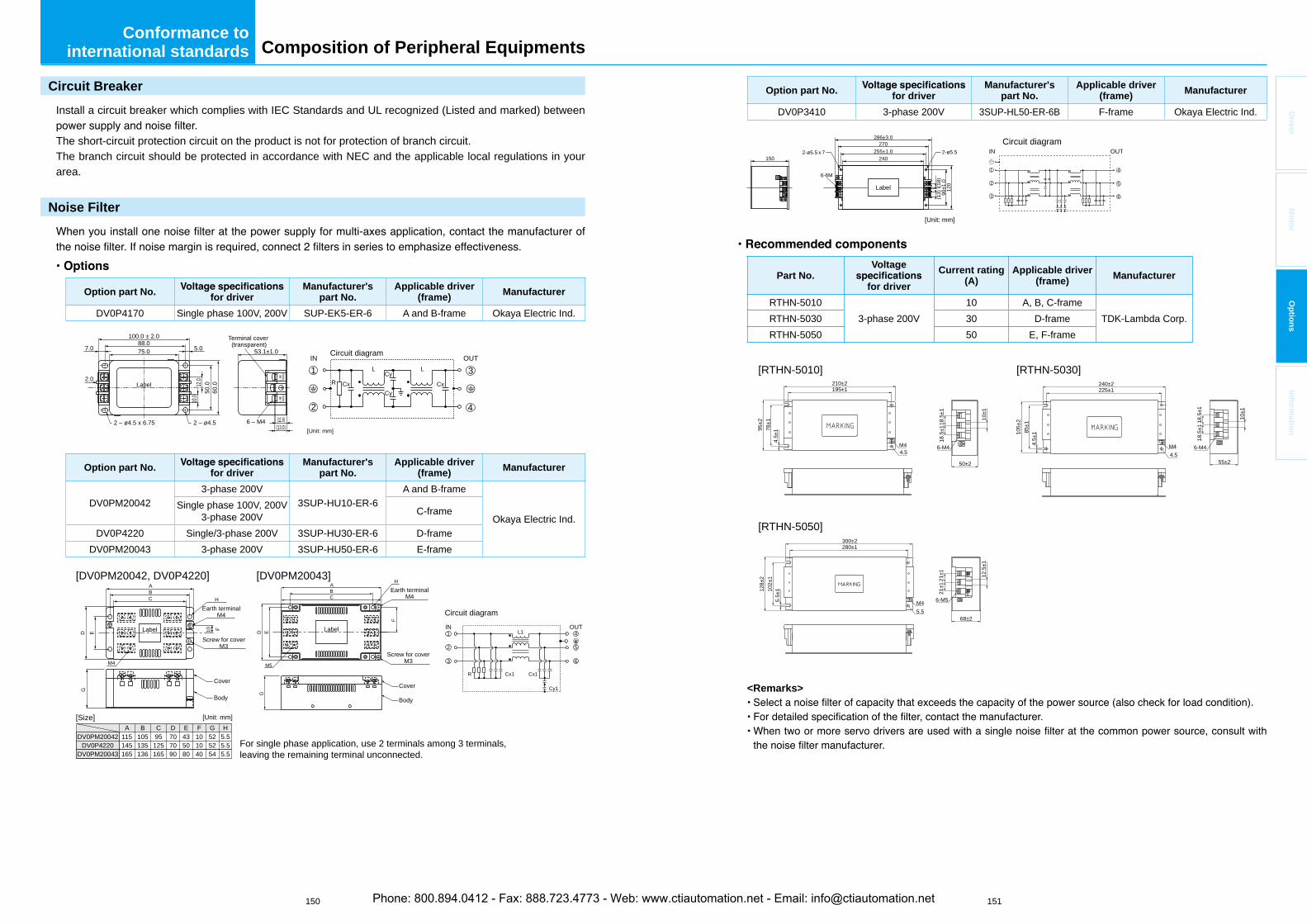
150 151
Driver
Mo
tor
Op
tion
sIn
form
ation
Composition of Peripheral Equipments
Circuit Breaker
Install a circuit breaker which complies with IEC Standards and UL recognized (Listed and marked) between
The short-circuit protection circuit on the product is not for protection of branch circuit.The branch circuit should be protected in accordance with NEC and the applicable local regulations in your area.
Noise Filter
Option part No. for driver Manufacturer's
part No.Applicable driver
(frame) Manufacturer
DV0P4170 Single phase 100V, 200V SUP-EK5-ER-6 A and B-frame Okaya Electric Ind.
[Unit: mm]
Label
Terminal cover (transparent)
2 – ø4.5
R Cx CxCy
L L
Cy
2 – ø4.5 x 6.75
53.1±1.0
100.0 ± 2.088.075.0 5.0
12.0
10.0
50.0
60.0
7.0
2.0
(11.6)(13.0)
6 – M4
2
1 3
4
Circuit diagramIN OUT
Option part No. for driver Manufacturer's
part No.Applicable driver
(frame) Manufacturer
DV0PM200423-phase 200V
3SUP-HU10-ER-6A and B-frame
Okaya Electric Ind.Single phase 100V, 200V
3-phase 200V C-frame
DV0P4220 Single/3-phase 200V 3SUP-HU30-ER-6 D-frameDV0PM20043 3-phase 200V 3SUP-HU50-ER-6 E-frame
A B C D E F G H115DV0PM20042
[DV0PM20042, DV0P4220] [DV0PM20043]
105 95 70 43 10 52 5.5145DV0P4220 135 125 70 50 10 52 5.5165DV0PM20043 136 165 90 80 40 54 5.5
Label
ABC H
10 F
EDG
Earth terminalM4
M4
Screw for coverM3
Cover
Body
4
5
1
2
63
Circuit diagram
L1
Cx1
IN OUT
R Cx1
Cy1
[Size] [Unit: mm]
Label
A
CB
H
M5
E
F
D
Earth terminalM4
Screw for coverM3
G
Cover
Body
For single phase application, use 2 terminals among 3 terminals, leaving the remaining terminal unconnected.
Conformance tointernational standards
Option part No. for driver Manufacturer's
part No.Applicable driver
(frame) Manufacturer
DV0P3410 3-phase 200V 3SUP-HL50-ER-6B F-frame Okaya Electric Ind.
[Unit: mm]
Circuit diagramIN OUT
286±3.0
1502-ø5.5 x 7 2-ø5.5
6-6M
270255±1.0
240
120
90±1
.0(18)
(13)
Label
1
2
3
4
5
6
Part No. Voltage
for driver
Current rating(A)
Applicable driver (frame) Manufacturer
RTHN-50103-phase 200V
10 A, B, C-frameTDK-Lambda Corp.RTHN-5030 30 D-frame
RTHN-5050 50 E, F-frame
[RTHN-5010]195±1210±2
50±2
6-M4M44.5
10±1
18.5
±178±1
4.5±
195±2 18
.5±1
[RTHN-5030]225±1240±2
55±2
6-M4M44.5
10±1
18.5
±185±1
4.5±
1105±
2 18.5
±1
[RTHN-5050]280±1300±2
68±2
6-M5M45.5
12.5
±1
21±1102±
15.
5±112
8±2 21
±1
<Remarks>
Phone: 800.894.0412 - Fax: 888.723.4773 - Web: www.ctiautomation.net - Email: [email protected]
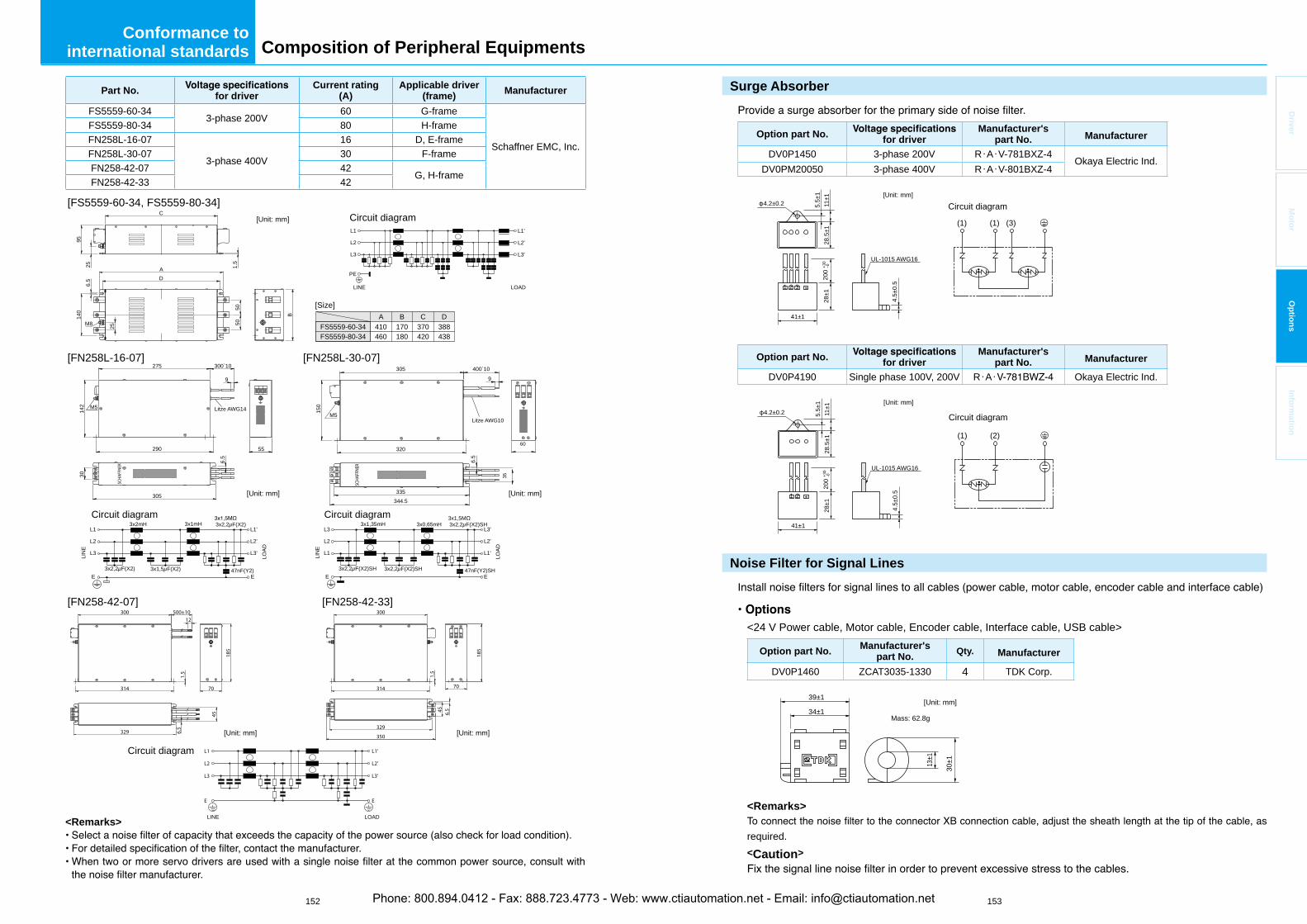
152 153
Driver
Mo
tor
Op
tion
sIn
form
ation
Surge Absorber
Option part No. for driver Manufacturer's
part No. Manufacturer
DV0P1450 3-phase 200V R・A・V-781BXZ-4Okaya Electric Ind.
DV0PM20050 3-phase 400V R・A・V-801BXZ-4
Circuit diagram
1
4.2±0.2
41±1
UL-1015 AWG16
28±1
5.5±
111
±128
.5±1
4.5±
0.5
200
+30
-0
2 3
(1) (1) (3)
[Unit: mm]
Option part No. for driver Manufacturer's
part No. Manufacturer
DV0P4190 Single phase 100V, 200V R・A・ Okaya Electric Ind.
Circuit diagram4.2±0.2
41±1
UL-1015 AWG16
28±1
5.5±
111
±128
.5±1
4.5±
0.5
200
+30
-0
1 2
(1) (2)
[Unit: mm]
Noise Filter for Signal Lines
I
<24 V Power cable, Motor cable, Encoder cable, Interface cable, USB cable>
Option part No. Manufacturer'spart No. Qty. Manufacturer
DV0P1460 ZCAT3035-1330 4 TDK Corp.
[Unit: mm]39±1
34±1
30±113±1
Mass: 62.8g
<Remarks>
required.<Caution>
Composition of Peripheral EquipmentsConformance to
international standards
Part No. for driver Current rating
(A)Applicable driver
(frame) Manufacturer
FS5559-60-343-phase 200V
60 G-frame
Schaffner EMC, Inc.
FS5559-80-34 80 H-frameFN258L-16-07
3-phase 400V
16 D, E-frameFN258L-30-07 30 F-frameFN258-42-07 42
G, H-frameFN258-42-33 42
[Unit: mm]
[Unit: mm] [Unit: mm]
[Size]
PE
LINE
L1
L3
L2
L1'
L3'
L2'
LOAD
C
5050
140
6.5 D
A
9525 1.
5
M8 25
B
Circuit diagram
Circuit diagram Circuit diagram
A B C D410FS5559-60-34 170 370 388460FS5559-80-34 180 420 438
[FS5559-60-34, FS5559-80-34]
[FN258L-16-07] [FN258L-30-07]
Litze AWG14M5
275
55290
305
142
150
30
6.5
6.5
300`10 305
320
335344.5
400`1099
47nF(Y2)
3x2,2μF(X2)
3x1,5μF(X2)
3x1mH3x2mH
3x2,2μF(X2)E
L3'
L2'
L1'
E
L3
L2
L1
LOAD
LIN
E
Litze AWG10M5
35
60
47nF(Y2)SH
3x1,5M3x2,2μF(X2)SH
3x2,2μF(X2)SH
3x0,65mH3x1,35mH
3x2,2μF(X2)SHE
L1'
L2'
L3'
E
L1
L2
L3
LOAD
LIN
E
LINE LOAD
Circuit diagram
[FN258-42-07] [FN258-42-33]
E E
L3
L2
L1
L3'
L2'
L1'
314
300
329
1.5
70
500±10
45
6.5
12
185
350
70314
329
45 6.5
300
185
1.5
[Unit: mm][Unit: mm]
<Remarks>
Phone: 800.894.0412 - Fax: 888.723.4773 - Web: www.ctiautomation.net - Email: [email protected]
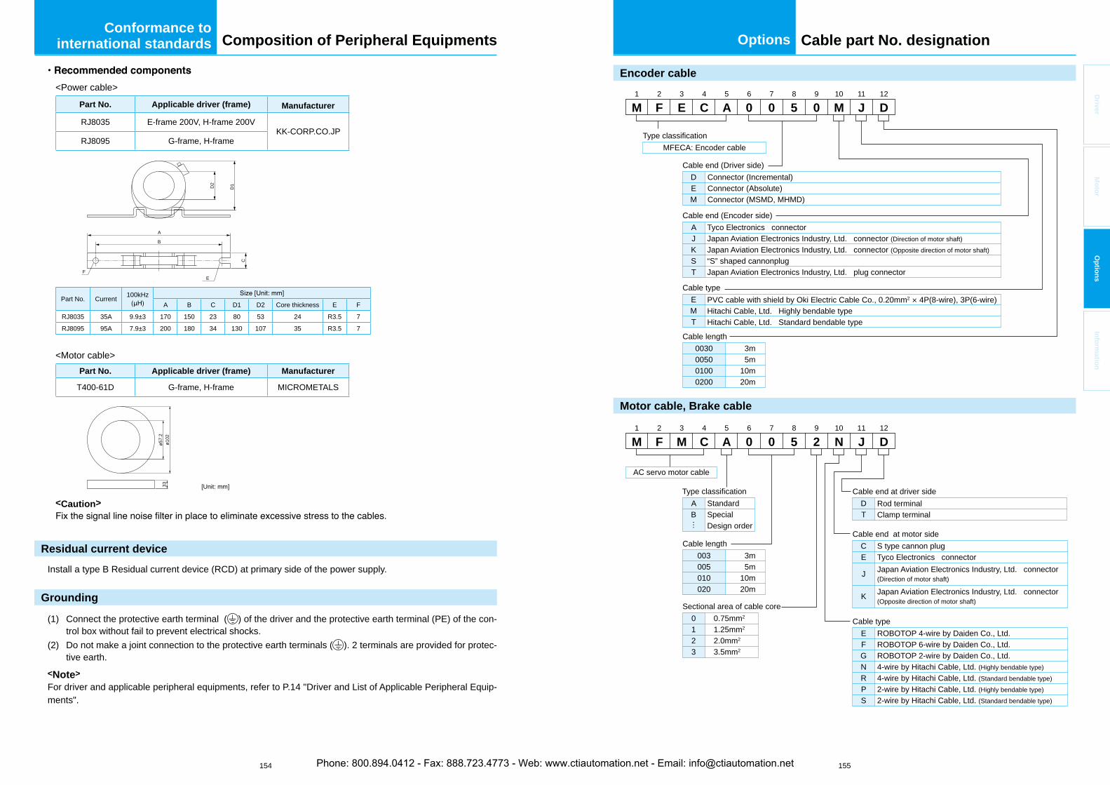
154 155
Options
Driver
Mo
tor
Op
tion
sIn
form
ation
Composition of Peripheral Equipments
<Power cable>Part No. Applicable driver (frame) Manufacturer
RJ8035 E-frame 200V, H-frame 200VKK-CORP.CO.JP
RJ8095 G-frame, H-frame
B
A
C
D1
FE
D2
Part No. Current 100kHzA B C D1 D2 Core thickness E F
RJ8035 35A 9.9±3 170 150 23 80 53 24 R3.5 7
RJ8095 95A 7.9±3 200 180 34 130 107 35 R3.5 7
<Motor cable>Part No. Applicable driver (frame) Manufacturer
T400-61D G-frame, H-frame MICROMETALS
ø57.
233
ø102
[Unit: mm]
<Caution>
Residual current device
Install a type B Residual current device (RCD) at primary side of the power supply.
Grounding
(1) Connect the protective earth terminal ( ) of the driver and the protective earth terminal (PE) of the con-trol box without fail to prevent electrical shocks.
(2) Do not make a joint connection to the protective earth terminals ( ). 2 terminals are provided for protec-tive earth.
<Note>
For driver and applicable peripheral equipments, refer to P.14 "Driver and List of Applicable Peripheral Equip-ments".
Conformance tointernational standards
Encoder cable
M1
F2
E3
C4
A5
06
07
58
09
M10
J11
D12
Connector (Incremental)Connector (Absolute)Connector (MSMD, MHMD)
DEM
Tyco Electronics connectorJapan Aviation Electronics Industry, Ltd. connector (Direction of motor shaft)Japan Aviation Electronics Industry, Ltd. connector (Opposite direction of motor shaft)“S” shaped cannonplugJapan Aviation Electronics Industry, Ltd. plug connector
AJKST
3m5m
10m20m
0030005001000200
PVC cable with shield by Oki Electric Cable Co., 0.20mm2 × 4P(8-wire), 3P(6-wire)Hitachi Cable, Ltd. Highly bendable typeHitachi Cable, Ltd. Standard bendable type
EMT
MFECA: Encoder cable
Cable end (Driver side)
Cable end (Encoder side)
Cable type
Cable length
Type classification
M1
F2
M3
C4
A5
06
07
58
29
N10
J11
D12
Rod terminalClamp terminal
DT
S type cannon plugTyco Electronics connectorJapan Aviation Electronics Industry, Ltd. connector(Direction of motor shaft)
Japan Aviation Electronics Industry, Ltd. connector(Opposite direction of motor shaft)
CE
J
K
3m5m
10m20m
003005010020
ROBOTOP 4-wire by Daiden Co., Ltd.ROBOTOP 6-wire by Daiden Co., Ltd.ROBOTOP 2-wire by Daiden Co., Ltd.4-wire by Hitachi Cable, Ltd. (Highly bendable type)4-wire by Hitachi Cable, Ltd. (Standard bendable type)2-wire by Hitachi Cable, Ltd. (Highly bendable type)2-wire by Hitachi Cable, Ltd. (Standard bendable type)
EFGNRPS
AC servo motor cable
Cable end at driver side
Cable end at motor side
Cable type
Cable length
0.75mm2
1.25mm2
2.0mm2
3.5mm2
0123
Sectional area of cable core
StandardSpecialDesign order
AB
Type classification
…
Cable part No. designation
Motor cable, Brake cable
Phone: 800.894.0412 - Fax: 888.723.4773 - Web: www.ctiautomation.net - Email: [email protected]
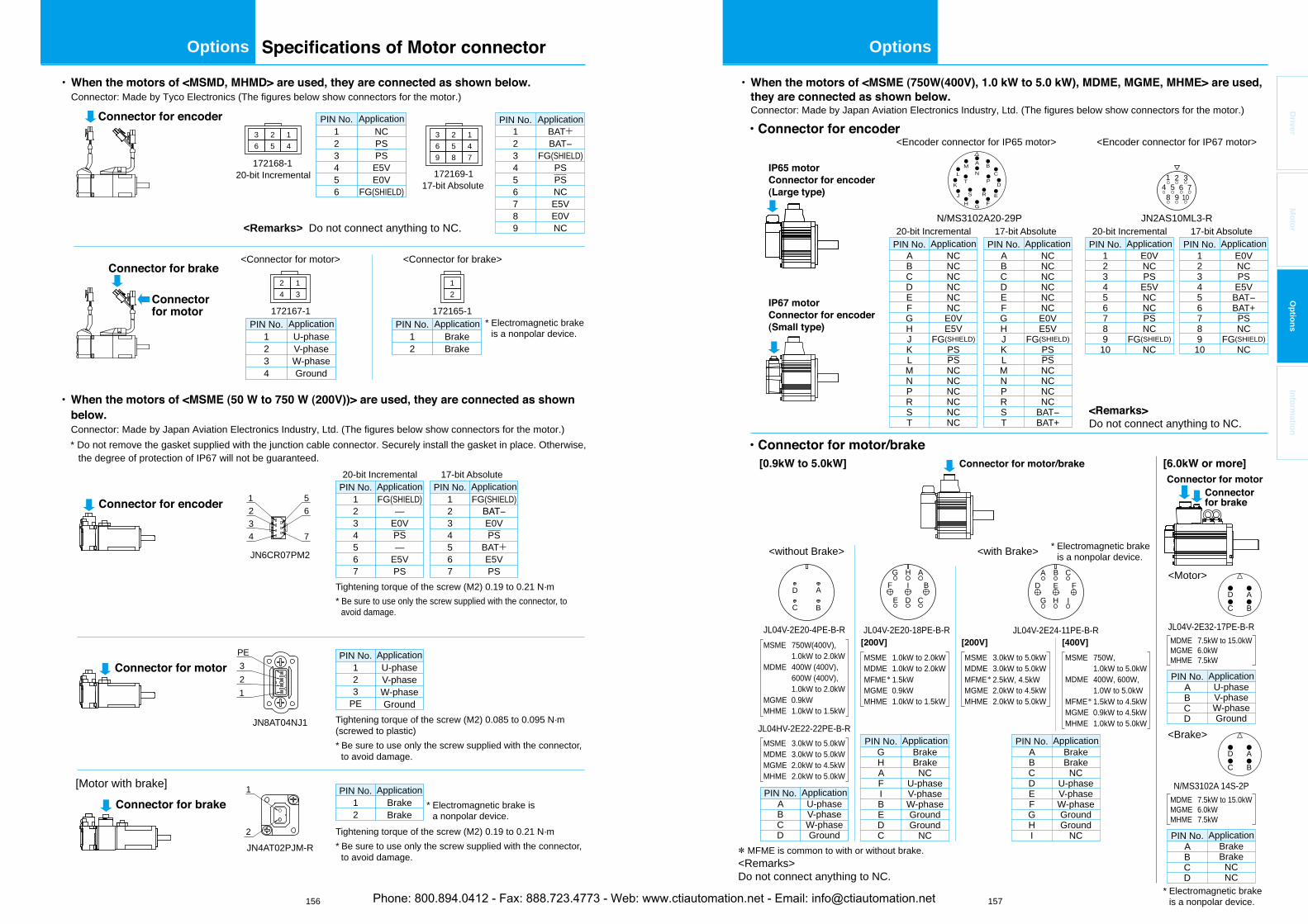
156 157
OptionsOptions
Driver
Motor
Options
Information
Specifications of Motor connector
<Remarks> Do not connect anything to NC.
JN6CR07PM2
20-bit Incremental 17-bit Absolute
• When the motors of <MSME (50 W to 750 W (200V))> are used, they are connected as shown below. Connector: Made by Japan Aviation Electronics Industry, Ltd. (The figures below show connectors for the motor.)
* Do not remove the gasket supplied with the junction cable connector. Securely install the gasket in place. Otherwise,the degree of protection of IP67 will not be guaranteed.
JN8AT04NJ1
1 U-phaseV-phaseW-phaseGround
PIN No.
23
PE
ApplicationPE321
2
1
JN4AT02PJM-R
12
BrakeBrake
PIN No. Application
1234
56
7
Connector for encoder
[Motor with brake]
Connector for motor
Tightening torque of the screw (M2) 0.085 to 0.095 N·m (screwed to plastic)* Be sure to use only the screw supplied with the connector,
to avoid damage.
Connector for brake
Tightening torque of the screw (M2) 0.19 to 0.21 N·m* Be sure to use only the screw supplied with the connector,
to avoid damage.
Tightening torque of the screw (M2) 0.19 to 0.21 N·m* Be sure to use only the screw supplied with the connector, to
avoid damage.
1234567
FG(SHIELD)—
E0VPS—
E5VPS
PIN No. Application1234567
FG(SHIELD)BAT−E0VPS
BAT+E5VPS
PIN No. Application
* Electromagnetic brake is a nonpolar device.
* Electromagnetic brake is a nonpolar device.
172167-1
172168-1
1 U-phaseV-phaseW-phaseGround
PIN No.
234
Application
• When the motors of <MSMD, MHMD> are used, they are connected as shown below. Connector: Made by Tyco Electronics (The figures below show connectors for the motor.)
172165-1
12
BrakeBrake
PIN No. Application
Connector for encoder
Connector for brake
Connector for motor
20-bit Incremental
123456
NCPSPS
E5VE0V
FG(SHIELD)
PIN No. Application
<Connector for motor> <Connector for brake>
2 14 3
12
3 2 16 5 4
172169-117-bit Absolute
123456789
BAT+BAT−
FG(SHIELD)PSPSNCE5VE0VNC
PIN No. Application3 2 16 5 49 8 7
• When the motors of <MSME (750W(400V), 1.0 kW to 5.0 kW), MDME, MGME, MHME> are used, they are connected as shown below. Connector: Made by Japan Aviation Electronics Industry, Ltd. (The figures below show connectors for the motor.)
JL04V-2E20-18PE-B-R
MSME 1.0kW to 2.0kWMDME 1.0kW to 2.0kWMFME* 1.5kWMGME 0.9kWMHME 1.0kW to 1.5kW
JL04V-2E24-11PE-B-R
MSME 3.0kW to 5.0kWMDME 3.0kW to 5.0kWMFME* 2.5kW, 4.5kWMGME 2.0kW to 4.5kWMHME 2.0kW to 5.0kW
MSME 750W, 1.0kW to 5.0kWMDME 400W, 600W, 1.0W to 5.0kWMFME* 1.5kW to 4.5kWMGME 0.9kW to 4.5kWMHME 1.0kW to 5.0kW
ABCD
JL04V-2E20-4PE-B-R
JL04HV-2E22-22PE-B-R
U-phaseV-phaseW-phaseGround
PIN No. Application
MSME 3.0kW to 5.0kWMDME 3.0kW to 5.0kWMGME 2.0kW to 4.5kWMHME 2.0kW to 5.0kW
MSME 750W(400V), 1.0kW to 2.0kWMDME 400W (400V), 600W (400V), 1.0kW to 2.0kWMGME 0.9kWMHME 1.0kW to 1.5kW
20-bit Incremental 17-bit Absolute
12345678910
E0VNCPS
E5VNCNCPSNC
FG(SHIELD)NC
PIN No. Application
JN2AS10ML3-R
1 2 3
8 9 107654
IP67 motorConnector for encoder(Small type)
IP65 motorConnector for encoder(Large type)
Connector for motor/brake
Connector for brake
[0.9kW to 5.0kW]
[200V] [200V]
• Connector for encoder
• Connector for motor/brake[6.0kW or more]Connector for motor
123456789
10
E0VNCPS
E5VBAT−BAT+
PSNC
FG(SHIELD)NC
PIN No. Application
GHAFIBEDC
BrakeBrake
NCU-phaseV-phaseW-phaseGroundGround
NC
PIN No. Application
<without Brake> <with Brake>
<Motor>
<Encoder connector for IP67 motor><Encoder connector for IP65 motor>
BC
D AIHG
FEDCBA
CDE
BIFAHG
JL04V-2E32-17PE-B-R
ABCD
U-phaseV-phaseW-phaseGround
PIN No. Application
MDME 7.5kW to 15.0kWMGME 6.0kWMHME 7.5kW
MDME 7.5kW to 15.0kWMGME 6.0kWMHME 7.5kW
N/MS3102A20-29P
A
NB
CP
D
ER
FGH
SJ
M
TL
K
20-bit Incremental 17-bit Absolute
ABCDEFGHJKLMNPRST
PIN No. ApplicationABCDEFGHJKLMNPRST
NCNCNCNCNCNCE0VE5V
FG(SHIELD)PSPSNCNCNCNC
BAT−BAT+
PIN No. ApplicationNCNCNCNCNCNCE0VE5V
FG(SHIELD)PSPSNCNCNCNCNCNC
* MFME is common to with or without brake.<Remarks> Do not connect anything to NC.
<Remarks> Do not connect anything to NC.
D ABC
<Brake>
N/MS3102A 14S-2P
ABCDEFGHI
BrakeBrake
NCU-phaseV-phaseW-phaseGroundGround
NC
PIN No. Application
[400V]
ABCD
BrakeBrake
NCNC
PIN No. Application
D ABC
* Electromagnetic brake is a nonpolar device.
* Electromagnetic brake is a nonpolar device.Phone: 800.894.0412 - Fax: 888.723.4773 - Web: www.ctiautomation.net - Email: [email protected]
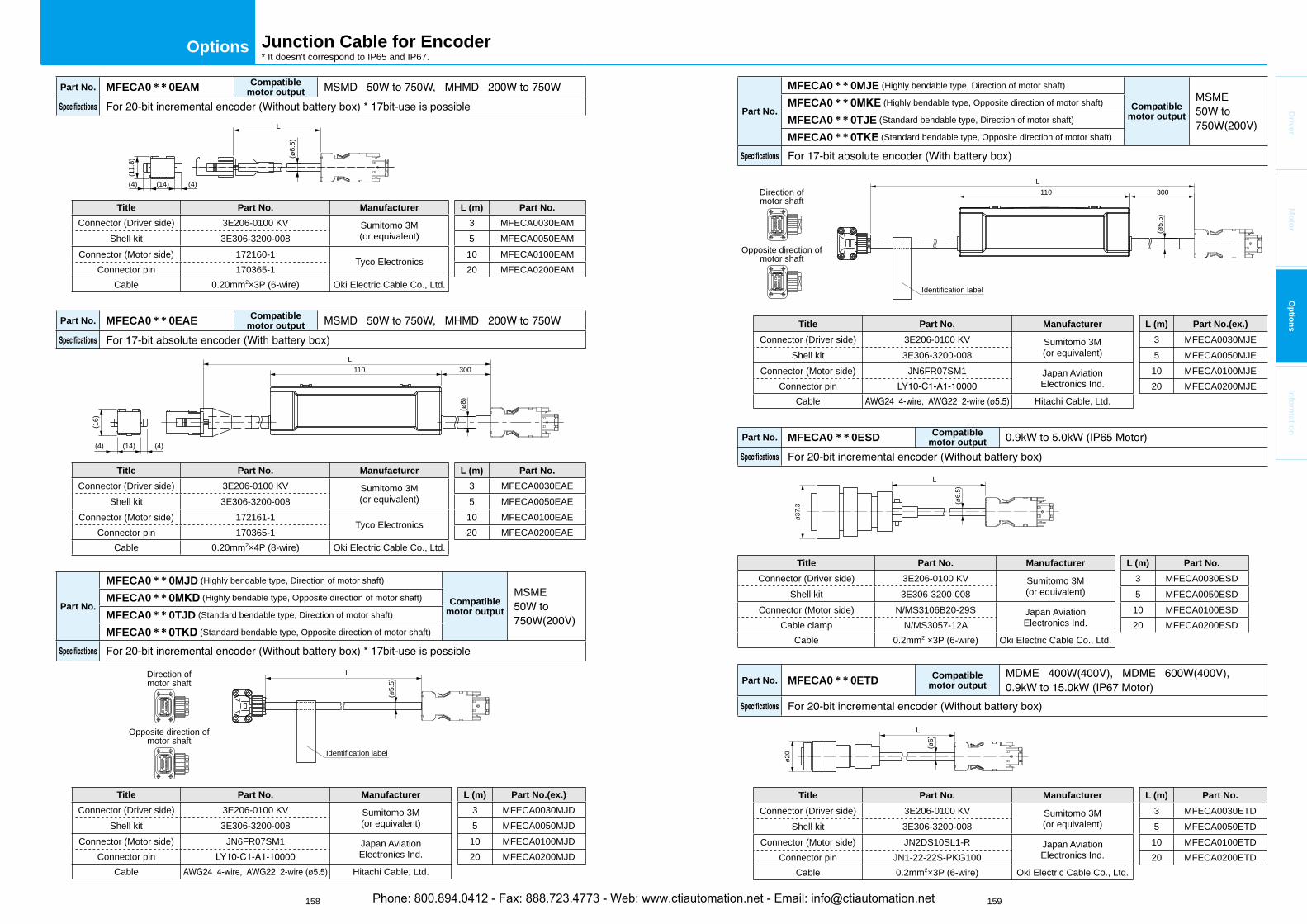
158 159
Options
Driver
Mo
tor
Op
tion
sIn
form
ation
Junction Cable for Encoder* It doesn't correspond to IP65 and IP67.
Part No. MFECA0 * * 0EAM Compatiblemotor output
L
(ø6.
5)
(14)
(11.
8)
(4) (4)
Title Part No. Manufacturer L (m) Part No.
Connector (Driver side) 3E206-0100 KV Sumitomo 3M(or equivalent)
3 MFECA0030EAMShell kit 3E306-3200-008 5 MFECA0050EAM
Connector (Motor side) 172160-1Tyco Electronics
10 MFECA0100EAMConnector pin 170365-1 20 MFECA0200EAM
Cable 0.20mm2×3P (6-wire) Oki Electric Cable Co., Ltd.
Part No. MFECA0 * * 0EAE Compatiblemotor output
(14)
(16)
(4) (4)
L110 300
(ø8)
Title Part No. Manufacturer L (m) Part No.
Connector (Driver side) 3E206-0100 KV Sumitomo 3M(or equivalent)
3 MFECA0030EAEShell kit 3E306-3200-008 5 MFECA0050EAE
Connector (Motor side) 172161-1Tyco Electronics
10 MFECA0100EAEConnector pin 170365-1 20 MFECA0200EAE
Cable 0.20mm2×4P (8-wire) Oki Electric Cable Co., Ltd.
Part No.
MFECA0 * * 0MJD (Highly bendable type, Direction of motor shaft)
Compatiblemotor output
MSMEMFECA0 * * (Highly bendable type, Opposite direction of motor shaft)
MFECA0 * * 0TJD (Standard bendable type, Direction of motor shaft)
MFECA0 * * (Standard bendable type, Opposite direction of motor shaft)
L
(ø5.
5)
Direction ofmotor shaft
Opposite direction ofmotor shaft
Identification label
Title Part No. Manufacturer L (m) Part No.(ex.)
Connector (Driver side) 3E206-0100 KV Sumitomo 3M(or equivalent)
3 MFECA0030MJDShell kit 3E306-3200-008 5 MFECA0050MJD
Connector (Motor side) JN6FR07SM1 Japan AviationElectronics Ind.
10 MFECA0100MJDConnector pin 20 MFECA0200MJD
Cable Hitachi Cable, Ltd.
Part No.
MFECA0 * * 0MJE (Highly bendable type, Direction of motor shaft)
Compatiblemotor output
MSMEMFECA0 * * (Highly bendable type, Opposite direction of motor shaft)
MFECA0 * * 0TJE (Standard bendable type, Direction of motor shaft)
MFECA0 * * (Standard bendable type, Opposite direction of motor shaft)
L110 300
(ø5.
5)
Direction ofmotor shaft
Opposite direction ofmotor shaft
Identification label
Title Part No. Manufacturer L (m) Part No.(ex.)
Connector (Driver side) 3E206-0100 KV Sumitomo 3M(or equivalent)
3 MFECA0030MJEShell kit 3E306-3200-008 5 MFECA0050MJE
Connector (Motor side) JN6FR07SM1 Japan AviationElectronics Ind.
10 MFECA0100MJEConnector pin 20 MFECA0200MJE
Cable Hitachi Cable, Ltd.
Part No. MFECA0 * * 0ESD Compatiblemotor output
L
(ø6.
5)
ø37.
3
Title Part No. Manufacturer L (m) Part No.
Connector (Driver side) 3E206-0100 KV Sumitomo 3M(or equivalent)
3 MFECA0030ESDShell kit 3E306-3200-008 5 MFECA0050ESD
Connector (Motor side) N/MS3106B20-29S Japan AviationElectronics Ind.
10 MFECA0100ESDCable clamp N/MS3057-12A 20 MFECA0200ESD
Cable 0.2mm2 ×3P (6-wire) Oki Electric Cable Co., Ltd.
Part No. MFECA0 * * 0ETD Compatiblemotor output
L
(ø6)
ø20
Title Part No. Manufacturer L (m) Part No.
Connector (Driver side) 3E206-0100 KV Sumitomo 3M(or equivalent)
3 MFECA0030ETDShell kit 3E306-3200-008 5 MFECA0050ETD
Connector (Motor side) JN2DS10SL1-R Japan AviationElectronics Ind.
10 MFECA0100ETDConnector pin JN1-22-22S-PKG100 20 MFECA0200ETD
Cable 0.2mm2×3P (6-wire) Oki Electric Cable Co., Ltd.
Phone: 800.894.0412 - Fax: 888.723.4773 - Web: www.ctiautomation.net - Email: [email protected]
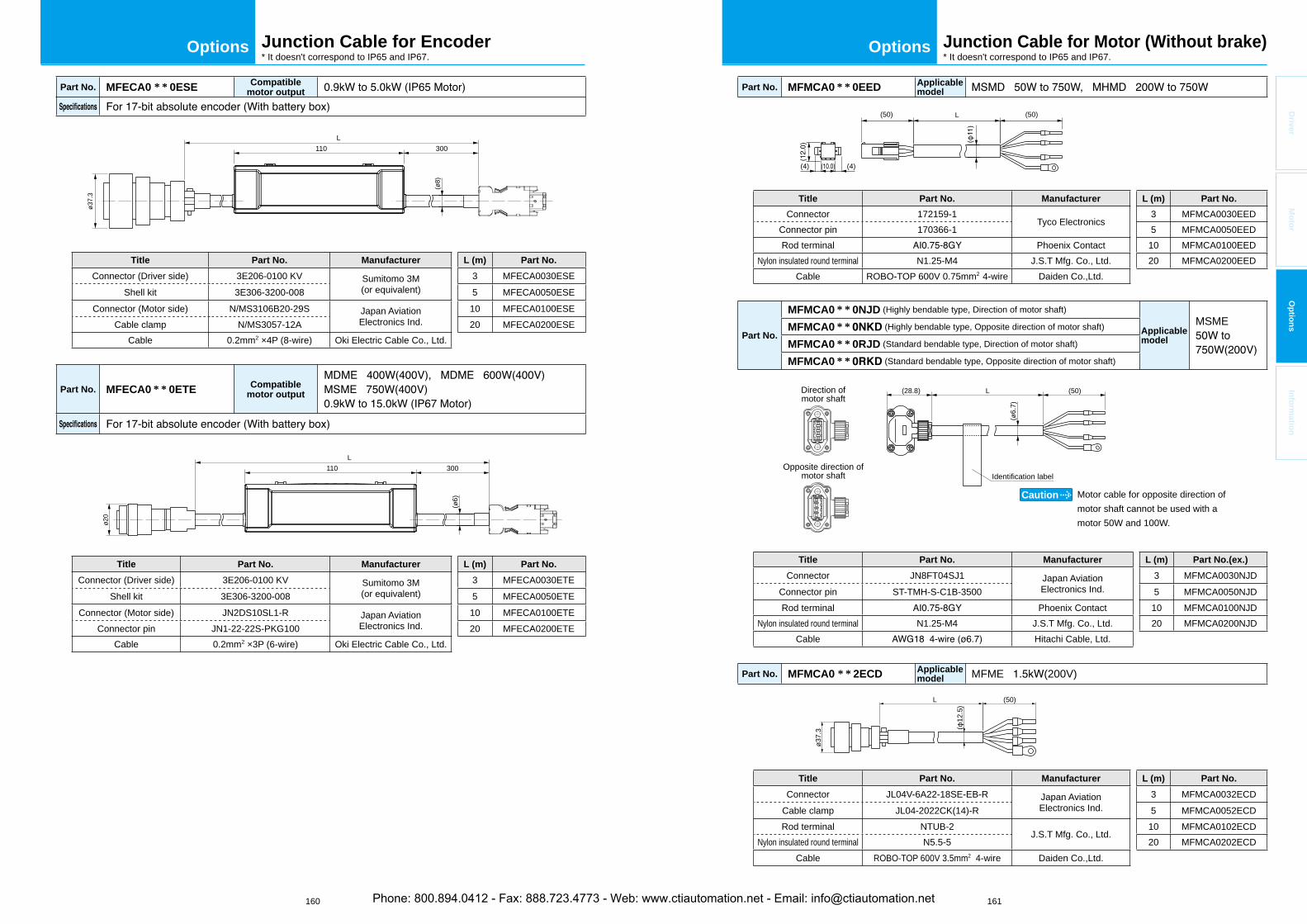
160 161
OptionsOptions
Driver
Mo
tor
Op
tion
sIn
form
ation
Part No. MFECA0 * * 0ESE Compatiblemotor output
(ø8)
ø37.
3
L110 300
Title Part No. Manufacturer L (m) Part No.
Connector (Driver side) 3E206-0100 KV Sumitomo 3M(or equivalent)
3 MFECA0030ESEShell kit 3E306-3200-008 5 MFECA0050ESE
Connector (Motor side) N/MS3106B20-29S Japan AviationElectronics Ind.
10 MFECA0100ESECable clamp N/MS3057-12A 20 MFECA0200ESE
Cable 0.2mm2 ×4P (8-wire) Oki Electric Cable Co., Ltd.
Part No. MFECA0 * * 0ETE Compatiblemotor output
L110 300
(ø6)
ø20
Title Part No. Manufacturer L (m) Part No.
Connector (Driver side) 3E206-0100 KV Sumitomo 3M(or equivalent)
3 MFECA0030ETEShell kit 3E306-3200-008 5 MFECA0050ETE
Connector (Motor side) JN2DS10SL1-R Japan AviationElectronics Ind.
10 MFECA0100ETEConnector pin JN1-22-22S-PKG100 20 MFECA0200ETE
Cable 0.2mm2 ×3P (6-wire) Oki Electric Cable Co., Ltd.
Junction Cable for Encoder* It doesn't correspond to IP65 and IP67.
Junction Cable for Motor (Without brake)* It doesn't correspond to IP65 and IP67.
Part No. MFMCA0 * * 0EED Applicablemodel
(50) (50)L
(4) (4)
Title Part No. Manufacturer L (m) Part No.
Connector 172159-1Tyco Electronics
3 MFMCA0030EEDConnector pin 170366-1 5 MFMCA0050EEDRod terminal Phoenix Contact 10 MFMCA0100EED
Nylon insulated round terminal N1.25-M4 J.S.T Mfg. Co., Ltd. 20 MFMCA0200EEDCable ROBO-TOP 600V 0.75mm2 4-wire Daiden Co.,Ltd.
Part No.
MFMCA0 * * 0NJD (Highly bendable type, Direction of motor shaft)
Applicablemodel
MSMEMFMCA0 * * (Highly bendable type, Opposite direction of motor shaft)
MFMCA0 * * 0RJD (Standard bendable type, Direction of motor shaft)
MFMCA0 * * (Standard bendable type, Opposite direction of motor shaft)
L (50)(28.8)
(ø6.
7)
Direction ofmotor shaft
Opposite direction ofmotor shaft
Motor cable for opposite direction of motor shaft cannot be used with a motor 50W and 100W.
Caution
Identification label
Title Part No. Manufacturer L (m) Part No.(ex.)
Connector JN8FT04SJ1 Japan AviationElectronics Ind.
3 MFMCA0030NJDConnector pin ST-TMH-S-C1B-3500 5 MFMCA0050NJDRod terminal Phoenix Contact 10 MFMCA0100NJD
Nylon insulated round terminal N1.25-M4 J.S.T Mfg. Co., Ltd. 20 MFMCA0200NJDCable Hitachi Cable, Ltd.
Part No. MFMCA0 * * 2ECD Applicablemodel MFME (200V)
(50)L
ø37.
3 (12
.5)
Title Part No. Manufacturer L (m) Part No.
Connector JL04V-6A22-18SE-EB-R Japan AviationElectronics Ind.
3 MFMCA0032ECDCable clamp JL04-2022CK(14)-R 5 MFMCA0052ECDRod terminal NTUB-2
J.S.T Mfg. Co., Ltd.10 MFMCA0102ECD
Nylon insulated round terminal N5.5-5 20 MFMCA0202ECDCable ROBO-TOP 600V 3.5mm2 4-wire Daiden Co.,Ltd.
Phone: 800.894.0412 - Fax: 888.723.4773 - Web: www.ctiautomation.net - Email: [email protected]
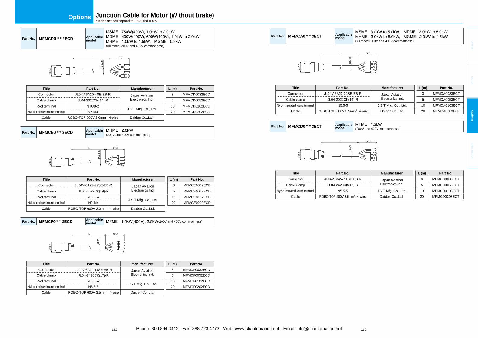
162 163
Options
Driver
Mo
tor
Op
tion
sIn
form
ation
Junction Cable for Motor (Without brake)* It doesn't correspond to IP65 and IP67.
Part No. MFMCD0 * * 2ECD Applicablemodel
(All model 200V and 400V commonness)
(50)L
ø37.
3 (12
.5)
Title Part No. Manufacturer L (m) Part No.
Connector JL04V-6A20-4SE-EB-R Japan AviationElectronics Ind.
3 MFMCD0032ECDCable clamp JL04-2022CK(14)-R 5 MFMCD0052ECDRod terminal NTUB-2
J.S.T Mfg. Co., Ltd.10 MFMCD0102ECD
Nylon insulated round terminal N2-M4 20 MFMCD0202ECDCable ROBO-TOP 600V 2.0mm2 4-wire Daiden Co.,Ltd.
Part No. MFMCE0 * * 2ECD Applicablemodel (200V and 400V commonness)
(50)L
(12
.5)
ø40.
5
Title Part No. Manufacturer L (m) Part No.
Connector JL04V-6A22-22SE-EB-R Japan AviationElectronics Ind.
3 MFMCE0032ECDCable clamp JL04-2022CK(14)-R 5 MFMCE0052ECDRod terminal NTUB-2
J.S.T Mfg. Co., Ltd.10 MFMCE0102ECD
Nylon insulated round terminal N2-M4 20 MFMCE0202ECDCable ROBO-TOP 600V 2.0mm2 4-wire Daiden Co.,Ltd.
Part No. MFMCF0 * * 2ECD Applicablemodel (200V and 400V commonness)
(50)L
ø43.
7 (14
)
Title Part No. Manufacturer L (m) Part No.
Connector JL04V-6A24-11SE-EB-R Japan AviationElectronics Ind.
3 MFMCF0032ECDCable clamp JL04-2428CK(17)-R 5 MFMCF0052ECDRod terminal NTUB-2
J.S.T Mfg. Co., Ltd.10 MFMCF0102ECD
Nylon insulated round terminal N5.5-5 20 MFMCF0202ECDCable ROBO-TOP 600V 3.5mm2 4-wire Daiden Co.,Ltd.
Part No. MFMCA0 * * 3ECT Applicablemodel
(All model 200V and 400V commonness)
(50)L
ø40.
5 (14
)
Title Part No. Manufacturer L (m) Part No.
Connector JL04V-6A22-22SE-EB-R Japan AviationElectronics Ind.
3 MFMCA0033ECTCable clamp JL04-2022CK(14)-R 5 MFMCA0053ECT
Nylon insulated round terminal N5.5-5 J.S.T Mfg. Co., Ltd. 10 MFMCA0103ECTCable ROBO-TOP 600V 3.5mm2 4-wire Daiden Co.,Ltd. 20 MFMCA0203ECT
Part No. MFMCD0 * * 3ECT Applicablemodel (200V and 400V commonness)
(50)L
ø43.
7 (14
)
Title Part No. Manufacturer L (m) Part No.
Connector JL04V-6A24-11SE-EB-R Japan AviationElectronics Ind.
3 MFMCD0033ECTCable clamp JL04-2428CK(17)-R 5 MFMCD0053ECT
Nylon insulated round terminal N5.5-5 J.S.T Mfg. Co., Ltd. 10 MFMCD0103ECTCable ROBO-TOP 600V 3.5mm2 4-wire Daiden Co.,Ltd. 20 MFMCD0203ECT
Phone: 800.894.0412 - Fax: 888.723.4773 - Web: www.ctiautomation.net - Email: [email protected]
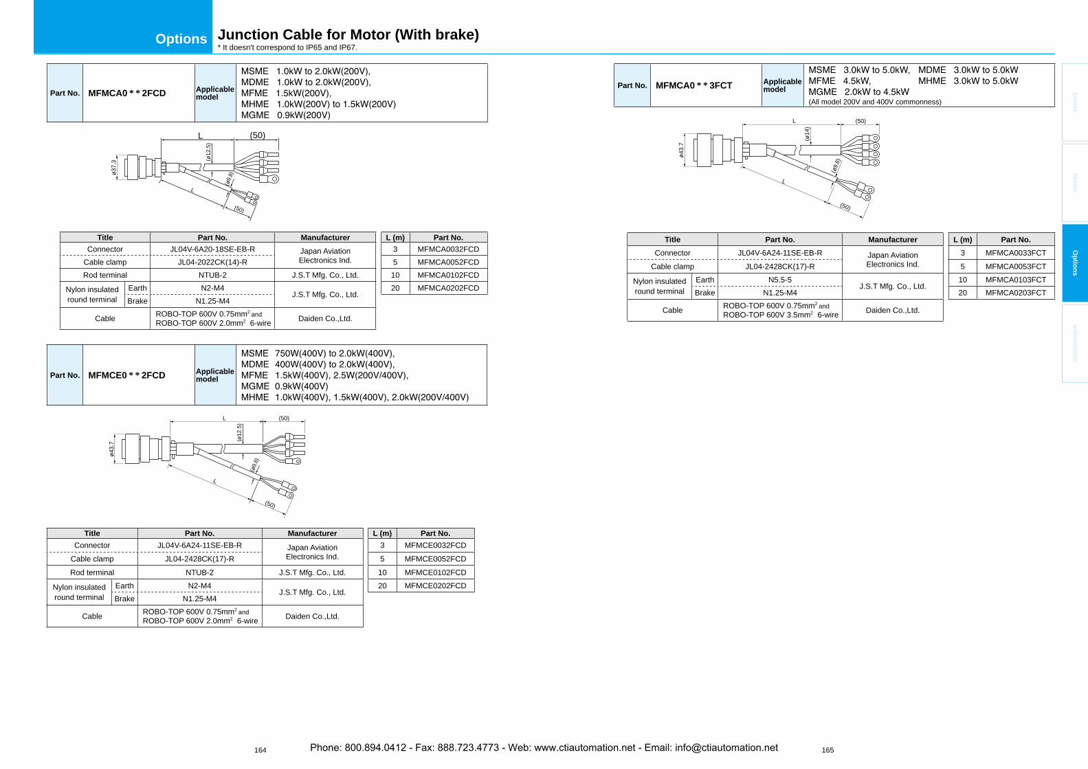
164 165
Options
Driver
Mo
tor
Op
tion
sIn
form
ation
Part No. MFMCA0 * * 2FCD Applicablemodel
L (50)
L
(50)(ø
12.5
)
(ø9.8
)ø37.
3
Title Part No. Manufacturer L (m) Part No.
Connector JL04V-6A20-18SE-EB-R Japan AviationElectronics Ind.
3 MFMCA0032FCDCable clamp JL04-2022CK(14)-R 5 MFMCA0052FCDRod terminal NTUB-2 J.S.T Mfg. Co., Ltd. 10 MFMCA0102FCD
Nylon insulatedround terminal
Earth N2-M4J.S.T Mfg. Co., Ltd.
20 MFMCA0202FCDBrake N1.25-M4
Cable ROBO-TOP 600V 0.75mm2 andROBO-TOP 600V 2.0mm2 6-wire Daiden Co.,Ltd.
Part No. MFMCE0 * * 2FCD Applicablemodel
(50)L
(50)
L
ø43.
7 (ø12
.5)
(ø9.8
)
Title Part No. Manufacturer L (m) Part No.
Connector JL04V-6A24-11SE-EB-R Japan AviationElectronics Ind.
3 MFMCE0032FCDCable clamp JL04-2428CK(17)-R 5 MFMCE0052FCDRod terminal NTUB-2 J.S.T Mfg. Co., Ltd. 10 MFMCE0102FCD
Nylon insulatedround terminal
Earth N2-M4J.S.T Mfg. Co., Ltd.
20 MFMCE0202FCDBrake N1.25-M4
Cable ROBO-TOP 600V 0.75mm2 andROBO-TOP 600V 2.0mm2 6-wire Daiden Co.,Ltd.
Junction Cable for Motor (With brake)* It doesn't correspond to IP65 and IP67.
Part No. MFMCA0 * * 3FCT Applicablemodel
(All model 200V and 400V commonness)
L (50)
L
(50)
ø43.
7
(ø14
)
(ø9.8
)
Title Part No. Manufacturer L (m) Part No.
Connector JL04V-6A24-11SE-EB-R Japan AviationElectronics Ind.
3 MFMCA0033FCTCable clamp JL04-2428CK(17)-R 5 MFMCA0053FCT
Nylon insulatedround terminal
Earth N5.5-5J.S.T Mfg. Co., Ltd.
10 MFMCA0103FCTBrake N1.25-M4 20 MFMCA0203FCT
Cable ROBO-TOP 600V 0.75mm2 andROBO-TOP 600V 3.5mm2 6-wire Daiden Co.,Ltd.
Phone: 800.894.0412 - Fax: 888.723.4773 - Web: www.ctiautomation.net - Email: [email protected]
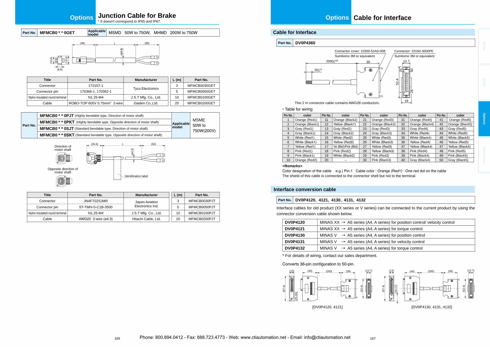
166 167
OptionsOptions
Driver
Mo
tor
Op
tion
sIn
form
ation
Junction Cable for Brake* It doesn't correspond to IP65 and IP67.
Part No. MFMCB0 * * 0GET Applicablemodel
L
Title Part No. Manufacturer L (m) Part No.
Connector 172157-1Tyco Electronics
3 MFMCB0030GETConnector pin 170366-1, 170362-1 5 MFMCB0050GET
Nylon insulated round terminal N1.25-M4 J.S.T Mfg. Co., Ltd. 10 MFMCB0100GETCable ROBO-TOP 600V 0.75mm2 2-wire Daiden Co.,Ltd. 20 MFMCB0200GET
Part No.
MFMCB0 * * 0PJT (Highly bendable type, Direction of motor shaft)
Applicablemodel
MSMEMFMCB0 * * (Highly bendable type, Opposite direction of motor shaft)
MFMCB0 * * 0SJT (Standard bendable type, Direction of motor shaft)
MFMCB0 * * (Standard bendable type, Opposite direction of motor shaft)
L (50)(26.6)Direction ofmotor shaft
Opposite direction ofmotor shaft
(ø4.
3)
Identification label
Title Part No. Manufacturer L (m) Part No.
Connector JN4FT02SJMR Japan AviationElectronics Ind.
3 MFMCB0030PJTConnector pin ST-TMH-S-C1B-3500 5 MFMCB0050PJT
Nylon insulated round terminal N1.25-M4 J.S.T Mfg. Co., Ltd. 10 MFMCB0100PJTCable Hitachi Cable, Ltd. 20 MFMCB0200PJT
Cable for Interface
Cable for Interface
Part No. DV0P4360
This 2 m connector cable contains AWG28 conductors.
25 50
52.4
2000+2000
50+100
39
Connector cover: 10350-52A0-008Sumitomo 3M or equivalent
Connector: 10150-3000PESumitomo 3M or equivalent
12.7
18
1 26
Pin No. color Pin No. color Pin No. color Pin No. color Pin No. color1 Orange (Red1) 11 Orange (Black2) 21 Orange (Red3) 31 Orange (Red4) 41 Orange (Red5)2 Orange (Black1) 12 22 Orange (Black3) 32 Orange (Black4) 42 Orange (Black5)3 Gray (Red1) 13 Gray (Red2) 23 Gray (Red3) 33 Gray (Red4) 43 Gray (Red5)4 Gray (Black1) 14 Gray (Black2) 24 Gray (Black3) 34 445 15 25 35 456 16 26 36 467 17 27 37 478 Pink (Red1) 18 Pink (Red2) 28 38 Pink (Red4) 48 Pink (Red5)9 Pink (Black1) 19 29 Pink (Red3) 39 Pink (Black4) 49 Pink (Black5)10 Orange (Red2) 20 – 30 Pink (Black3) 40 Gray (Black4) 50 Gray (Black5)
<Remarks>
The shield of this cable is connected to the connector shell but not to the terminal.
Interface conversion cable
Part No. DV0P4120, 4121, 4130, 4131, 4132
Interface cables for old product (XX series or V series) can be connected to the current product by using the connector conversion cable shown below.
DV0P4120 MINAS XX → A5 series (A4, A series) for position control/ velocity controlDV0P4121 MINAS XX → A5 series (A4, A series) for torque controlDV0P4130 MINAS V → A5 series (A4, A series) for position controlDV0P4131 MINAS V → A5 series (A4, A series) for velocity controlDV0P4132 MINAS V → A5 series (A4, A series) for torque control
* For details of wiring, contact our sales department.
(13)
(67.
4)
(52.
4)
(52.
4)
(67.
4)
(16.
17)
(25.
06)
(40) (13) (40) (200) (39) (12.7)(200) (39) (12.7)
[DV0P4120, 4121] [DV0P4130, 4131, 4132]
Phone: 800.894.0412 - Fax: 888.723.4773 - Web: www.ctiautomation.net - Email: [email protected]
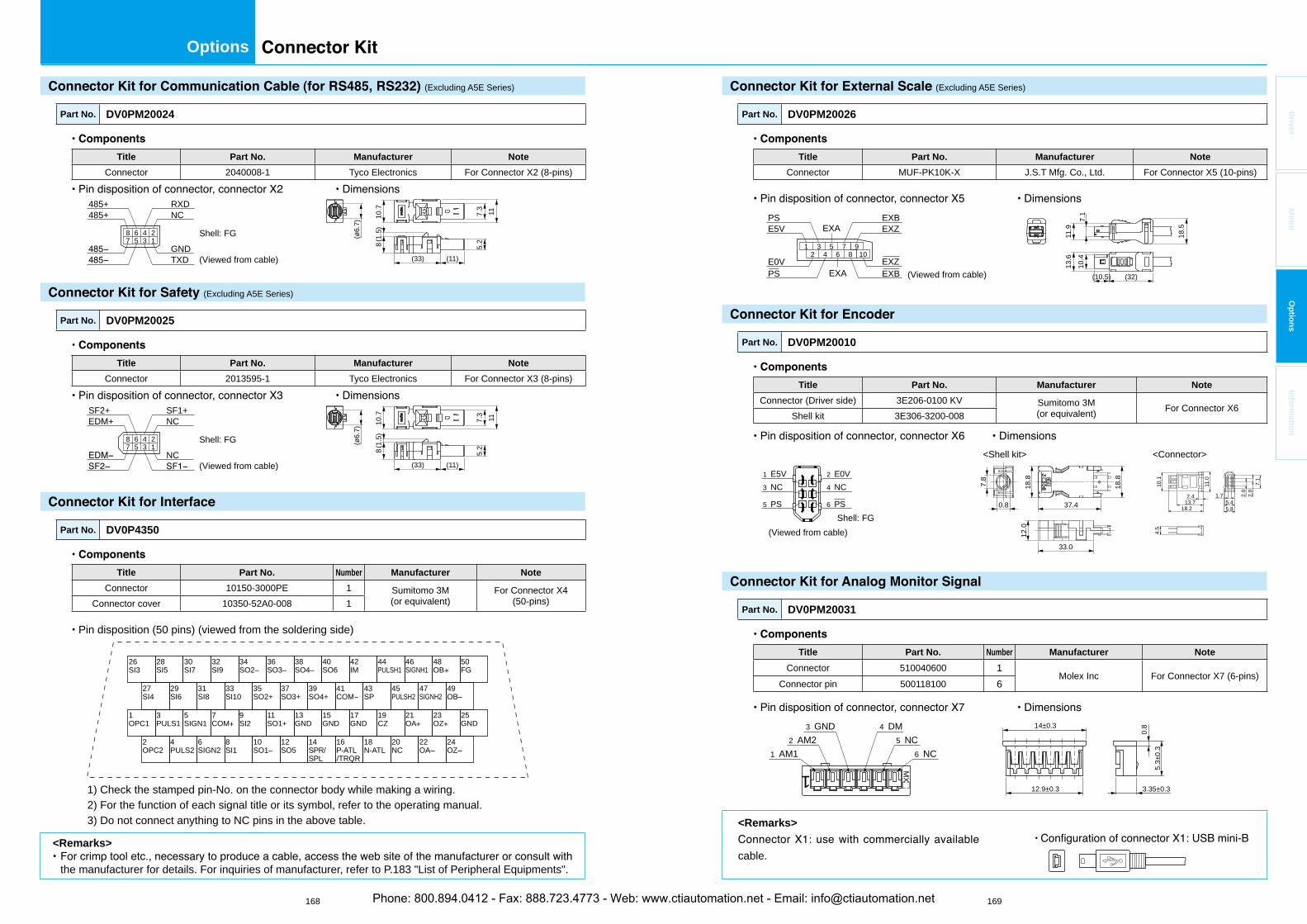
168 169
Options
Driver
Mo
tor
Op
tion
sIn
form
ation
(Excluding A5E Series)
Part No. DV0PM20024
Title Part No. Manufacturer Note
Connector 2040008-1 Tyco Electronics For Connector X2 (8-pins)
(33) (11)
5.2
7.3
(ø6.
7)
1110.7
8(1.
5)
(Viewed from cable)
Shell: FGGNDTXD
NCRXD485+
485+
8 6 4 27 5 3 1
(Excluding A5E Series)
Part No. DV0PM20025
Title Part No. Manufacturer Note
Connector 2013595-1 Tyco Electronics For Connector X3 (8-pins)
(33) (11)
5.2
7.3
(ø6.
7)
1110.7
8(1.
5)8 6 4 27 5 3 1
NC
NCSF1+SF2+
EDM+
(Viewed from cable)
Shell: FG
Part No. DV0P4350
Title Part No. Number Manufacturer Note
Connector 10150-3000PE 1 Sumitomo 3M(or equivalent)
For Connector X4 (50-pins)Connector cover 10350-52A0-008 1
Pin disposition (50 pins) (viewed from the soldering side)
1) Check the stamped pin-No. on the connector body while making a wiring. 2) For the function of each signal title or its symbol, refer to the operating manual. 3) Do not connect anything to NC pins in the above table.
26SI3
28SI5
30SI7
32SI9
34SO2–
36SO3–
38SO4–
40SO6
42IM
44PULSH1
46SIGNH1
48OB
27SI4
29SI6
31SI8
33SI10
35SO2+
37SO3+
39SO4+
41COM
43SP
45PULSH2
47SIGNH2
49OB
1OPC1
3PULS1
5SIGN1
7COM
9SI2
11SO1+
13GND
15GND
17GND
19CZ
21OA
23OZ
2OPC2
4PULS2
6SIGN2
8SI1
10SO1–
12SO5
14SPR/SPL /TRQR
16P-ATL
18N-ATL
20NC
22OA
24OZ
50FG
25GND
(Excluding A5E Series)
Part No. DV0PM20026
Title Part No. Manufacturer Note
Connector MUF-PK10K-X J.S.T Mfg. Co., Ltd. For Connector X5 (10-pins)
(10.5) (32)
18.5
13.6
10.4
11.9
7.1
1 3 5 72 4 6 8
910
PS EXA
EXA
E0V
EXZ
EXZ
EXB
EXB
PSE5V
(Viewed from cable)
Part No. DV0PM20010
Title Part No. Manufacturer Note
Connector (Driver side) 3E206-0100 KV Sumitomo 3M(or equivalent) For Connector X6
Shell kit 3E306-3200-008
(Viewed from cable)
<Shell kit> <Connector>
Shell: FG
33.0
37.40.8
7.8
18.8
18.8
12.0
6 PS5 PS
2 E0V1 E5V4 NC3 NC
5.85.4
1.7
7.1
2.0
2.0
11.0
10.1
4.5
18.213.72.4
Part No. DV0PM20031
Title Part No. Number Manufacturer Note
Connector 510040600 1Molex Inc For Connector X7 (6-pins)
Connector pin 500118100 6
1 MX
1 AM12 AM2
3 GND
6 NC5 NC
4 DM 14±0.3
12.9±0.3 3.35±0.3
0.8
5.3±
0.3
<Remarks>
cable.
<Remarks>
the manufacturer for details. For inquiries of manufacturer, refer to P.183 "List of Peripheral Equipments".
Phone: 800.894.0412 - Fax: 888.723.4773 - Web: www.ctiautomation.net - Email: [email protected]

170 171
Options
Driver
Mo
tor
Op
tion
sIn
form
ation
Part No. DV0PM20032
Title Part No. Number Manufacturer Note
Connector 05JFAT-SAXGF 1J.S.T Mfg. Co., Ltd. For Connector XA
Handle lever J-FAT-OT 2
Part No. DV0PM20033
Title Part No. Number Manufacturer Note
Connector 05JFAT-SAXGSA-C 1J.S.T Mfg. Co., Ltd. For Connector XA
Handle lever J-FAT-OT 2
39.3
27.6
26
1235 4
A
B
5 4 2 1
5 4 2 1
3
3
Part No. DV0PM20044 (For E-frame 200V)
Title Part No. Number Manufacturer Note
Connector 05JFAT-SAXGSA-L 1J.S.T Mfg. Co., Ltd. For Connector XA
Handle lever J-FAT-OT-L 2
Part No. DV0PM20051 (For D-frame 400V)
Title Part No. Number Manufacturer Note
Connector 1J.S.T Mfg. Co., Ltd. For Connector XA
Handle lever J-FAT-OT-L 2
Part No. DV0PM20052 (For E-frame 400V)
Title Part No. Number Manufacturer Note
Connector 1J.S.T Mfg. Co., Ltd. For Connector XA
Handle lever J-FAT-OT-L 2
Part No. DV0PM20053 (For D, E-frame 400V)
Title Part No. Number Manufacturer Note
Connector 02MJFAT-SAGF 1J.S.T Mfg. Co., Ltd. For Connector XD
Handle lever MJFAT-0T 1
Part No. DV0PM20045 (For E-frame 200V/400V)
Title Part No. Number Manufacturer Note
Connector 04JFAT-SAXGSA-L 1J.S.T Mfg. Co., Ltd. For Connector XC
* Jumper wire is included.Handle lever J-FAT-OT-L 2
Part No. DV0PM20055 (For D-frame 400V)
Title Part No. Number Manufacturer Note
Connector 04JFAT-SAXGSA-M 1J.S.T Mfg. Co., Ltd. For Connector XC
Handle lever J-FAT-OT-L 2
Part No. DV0PM20034 (For A to C-frame 100V, A to D-frame 200V)
Title Part No. Number Manufacturer Note
Connector 06JFAT-SAXGF 1J.S.T Mfg. Co., Ltd. For Connector XB
* Jumper wire is included.Handle lever J-FAT-OT 2
Part No. DV0PM20046 (For E-frame 200V/400V)
Title Part No. Number Manufacturer Note
Connector 03JFAT-SAXGSA-L 1J.S.T Mfg. Co., Ltd. For Connector XB
Handle lever J-FAT-OT-L 2
Part No. DV0PM20054 (For D-frame 400V)
Title Part No. Number Manufacturer Note
Connector 03JFAT-SAXGSA-M 1J.S.T Mfg. Co., Ltd. For Connector XB
Handle lever J-FAT-OT-L 2
Phone: 800.894.0412 - Fax: 888.723.4773 - Web: www.ctiautomation.net - Email: [email protected]
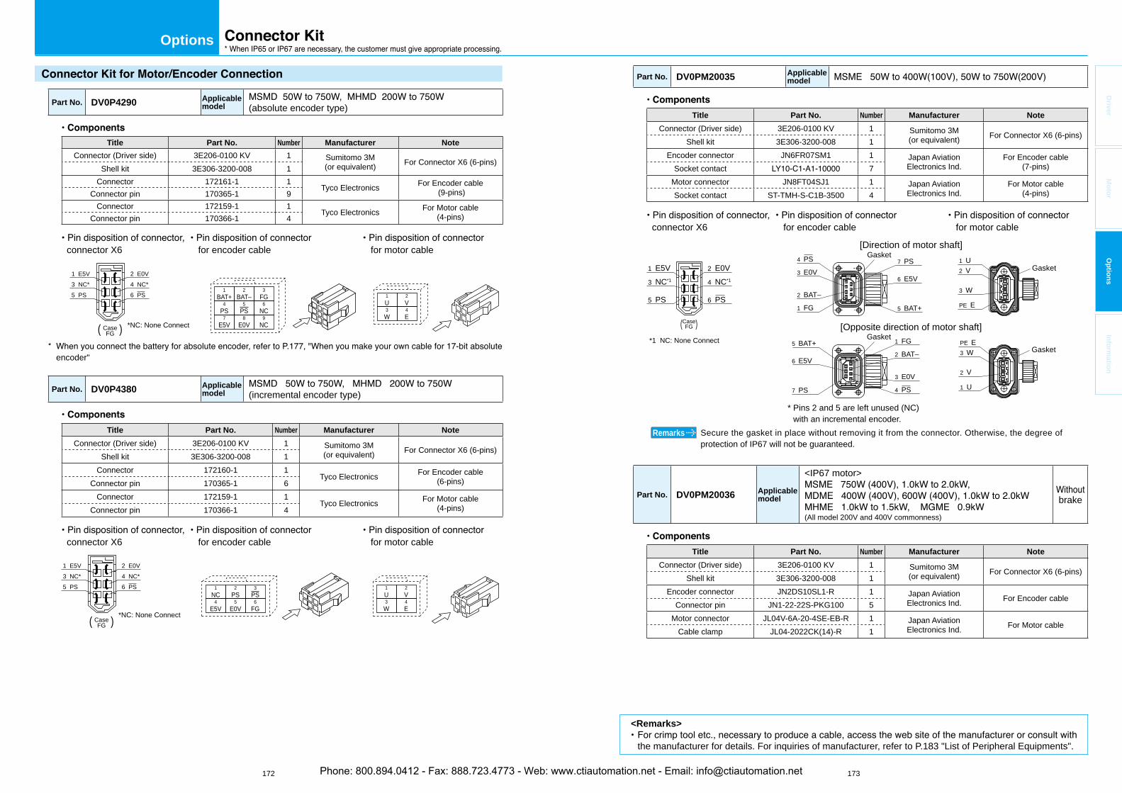
172 173
Options
Driver
Mo
tor
Op
tion
sIn
form
ation
Part No. DV0P4290 Applicablemodel (absolute encoder type)
Title Part No. Number Manufacturer Note
Connector (Driver side) 3E206-0100 KV 1 Sumitomo 3M(or equivalent) For Connector X6 (6-pins)
Shell kit 3E306-3200-008 1Connector 172161-1 1
Tyco Electronics For Encoder cable (9-pins)Connector pin 170365-1 9
Connector 172159-1 1Tyco Electronics For Motor cable
(4-pins)Connector pin 170366-1 4
connector X6 for encoder cable for motor cable
( )
6 PS5 PS
2 E0V1 E5V4 NC*3 NC*
CaseFG
1BAT+
2BAT–
3FG
4PS
5PS
6NC
7E5V
8E0V
9NC
1U
2V
3W
4E
*NC: None Connect
encoder"
Part No. DV0P4380 Applicablemodel (incremental encoder type)
Title Part No. Number Manufacturer Note
Connector (Driver side) 3E206-0100 KV 1 Sumitomo 3M(or equivalent) For Connector X6 (6-pins)
Shell kit 3E306-3200-008 1Connector 172160-1 1
Tyco Electronics For Encoder cable(6-pins)Connector pin 170365-1 6
Connector 172159-1 1Tyco Electronics For Motor cable
(4-pins)Connector pin 170366-1 4
connector X6 for encoder cable for motor cable
6 PS5 PS
2 E0V1 E5V4 NC* 3 NC*
CaseFG
1NC
2PS
3PS
4E5V
5E0V
6FG
1U
2V
3W
4E
( ) *NC: None Connect
Part No. DV0PM20035 Applicablemodel
Title Part No. Number Manufacturer Note
Connector (Driver side) 3E206-0100 KV 1 Sumitomo 3M(or equivalent) For Connector X6 (6-pins)
Shell kit 3E306-3200-008 1Encoder connector JN6FR07SM1 1 Japan Aviation
Electronics Ind.For Encoder cable
(7-pins)Socket contact 7Motor connector JN8FT04SJ1 1 Japan Aviation
Electronics Ind.For Motor cable
(4-pins)Socket contact ST-TMH-S-C1B-3500 4
connector X6 for encoder cable for motor cable
6 PS5 PS
2 E0V1 E5V4 NC*1
*1 NC: None Connect
3 NC*1
(Case)FG
4 PS
1 FG
2 BAT–
3 E0V
5 BAT+
6 E5V
7 PS
1 FG
4 PS
2 BAT–
3 E0V
7 PS
6 E5V
5 BAT+ PE E3 W
2 V
1 U
1 U2 V
3 W
PE E
[Direction of motor shaft]
[Opposite direction of motor shaft]
* Pins 2 and 5 are left unused (NC) with an incremental encoder.
GasketGasket
GasketGasket
Secure the gasket in place without removing it from the connector. Otherwise, the degree of protection of IP67 will not be guaranteed.
Remarks
Part No. DV0PM20036 Applicablemodel
<IP67 motor>
(All model 200V and 400V commonness)
brake
Title Part No. Number Manufacturer Note
Connector (Driver side) 3E206-0100 KV 1 Sumitomo 3M(or equivalent) For Connector X6 (6-pins)
Shell kit 3E306-3200-008 1Encoder connector JN2DS10SL1-R 1 Japan Aviation
Electronics Ind. For Encoder cableConnector pin JN1-22-22S-PKG100 5
Motor connector JL04V-6A-20-4SE-EB-R 1 Japan AviationElectronics Ind. For Motor cable
Cable clamp JL04-2022CK(14)-R 1
<Remarks>
the manufacturer for details. For inquiries of manufacturer, refer to P.183 "List of Peripheral Equipments".
Phone: 800.894.0412 - Fax: 888.723.4773 - Web: www.ctiautomation.net - Email: [email protected]
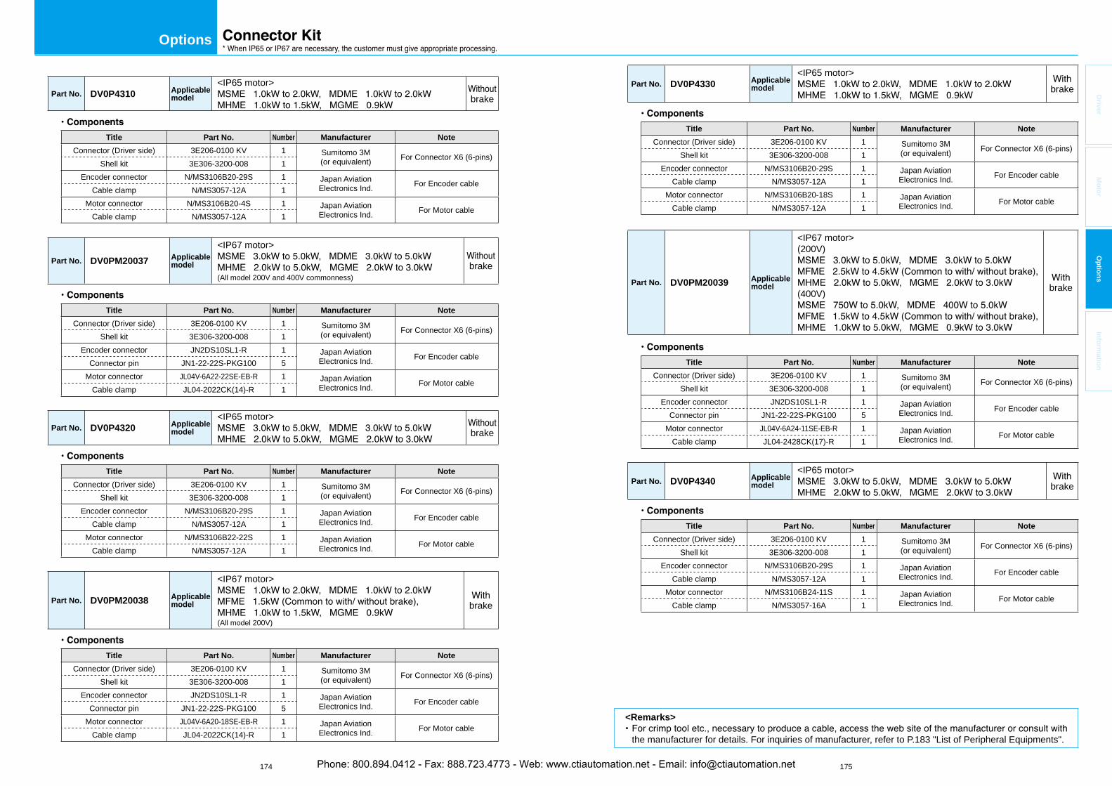
174 175
Options
Driver
Mo
tor
Op
tion
sIn
form
ation
Part No. DV0P4310 Applicablemodel
<IP65 motor>brake
Title Part No. Number Manufacturer Note
Connector (Driver side) 3E206-0100 KV 1 Sumitomo 3M(or equivalent) For Connector X6 (6-pins)
Shell kit 3E306-3200-008 1Encoder connector N/MS3106B20-29S 1 Japan Aviation
Electronics Ind. For Encoder cableCable clamp N/MS3057-12A 1
Motor connector N/MS3106B20-4S 1 Japan AviationElectronics Ind. For Motor cable
Cable clamp N/MS3057-12A 1
Part No. DV0PM20037 Applicablemodel
<IP67 motor>
(All model 200V and 400V commonness)brake
Title Part No. Number Manufacturer Note
Connector (Driver side) 3E206-0100 KV 1 Sumitomo 3M(or equivalent) For Connector X6 (6-pins)
Shell kit 3E306-3200-008 1Encoder connector JN2DS10SL1-R 1 Japan Aviation
Electronics Ind. For Encoder cableConnector pin JN1-22-22S-PKG100 5
Motor connector JL04V-6A22-22SE-EB-R 1 Japan AviationElectronics Ind. For Motor cable
Cable clamp JL04-2022CK(14)-R 1
Part No. DV0P4320 Applicablemodel
<IP65 motor>brake
Title Part No. Number Manufacturer Note
Connector (Driver side) 3E206-0100 KV 1 Sumitomo 3M(or equivalent) For Connector X6 (6-pins)
Shell kit 3E306-3200-008 1Encoder connector N/MS3106B20-29S 1 Japan Aviation
Electronics Ind. For Encoder cableCable clamp N/MS3057-12A 1
Motor connector N/MS3106B22-22S 1 Japan AviationElectronics Ind. For Motor cable
Cable clamp N/MS3057-12A 1
Part No. DV0PM20038 Applicablemodel
<IP67 motor>
(All model 200V)
brake
Title Part No. Number Manufacturer Note
Connector (Driver side) 3E206-0100 KV 1 Sumitomo 3M(or equivalent) For Connector X6 (6-pins)
Shell kit 3E306-3200-008 1Encoder connector JN2DS10SL1-R 1 Japan Aviation
Electronics Ind. For Encoder cableConnector pin JN1-22-22S-PKG100 5
Motor connector JL04V-6A20-18SE-EB-R 1 Japan AviationElectronics Ind. For Motor cable
Cable clamp JL04-2022CK(14)-R 1
Part No. DV0P4330 Applicablemodel
<IP65 motor>brake
Title Part No. Number Manufacturer Note
Connector (Driver side) 3E206-0100 KV 1 Sumitomo 3M(or equivalent) For Connector X6 (6-pins)
Shell kit 3E306-3200-008 1Encoder connector N/MS3106B20-29S 1 Japan Aviation
Electronics Ind. For Encoder cableCable clamp N/MS3057-12A 1
Motor connector N/MS3106B20-18S 1 Japan AviationElectronics Ind. For Motor cable
Cable clamp N/MS3057-12A 1
Part No. DV0PM20039 Applicablemodel
<IP67 motor>(200V)
(400V) brake
Title Part No. Number Manufacturer Note
Connector (Driver side) 3E206-0100 KV 1 Sumitomo 3M(or equivalent) For Connector X6 (6-pins)
Shell kit 3E306-3200-008 1Encoder connector JN2DS10SL1-R 1 Japan Aviation
Electronics Ind. For Encoder cableConnector pin JN1-22-22S-PKG100 5
Motor connector JL04V-6A24-11SE-EB-R 1 Japan AviationElectronics Ind. For Motor cable
Cable clamp JL04-2428CK(17)-R 1
Part No. DV0P4340 Applicablemodel
<IP65 motor>brake
Title Part No. Number Manufacturer Note
Connector (Driver side) 3E206-0100 KV 1 Sumitomo 3M(or equivalent) For Connector X6 (6-pins)
Shell kit 3E306-3200-008 1Encoder connector N/MS3106B20-29S 1 Japan Aviation
Electronics Ind. For Encoder cableCable clamp N/MS3057-12A 1
Motor connector N/MS3106B24-11S 1 Japan AviationElectronics Ind. For Motor cable
Cable clamp N/MS3057-16A 1
<Remarks>
the manufacturer for details. For inquiries of manufacturer, refer to P.183 "List of Peripheral Equipments".
Phone: 800.894.0412 - Fax: 888.723.4773 - Web: www.ctiautomation.net - Email: [email protected]
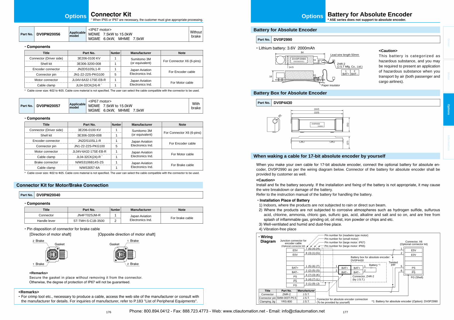
176 177
OptionsOptions
Driver
Mo
tor
Op
tion
sIn
form
ation
Battery for Absolute Encoder
Part No. DV0P2990
DV0P29900 0 0 9 0 0 0 1
84
18
Paper insulator
Lead wire length 50mm
ZHR-2(J.S.T Mfg. Co., Ltd.)
1BAT+
14.52
BAT–
Battery Box for Absolute Encoder
Part No. DV0P4430
DV0P4430P04090001*
R5
(112)(110)
(31)
(27)
When waking a cable for 17-bit absolute encoder by yourself
-coder, DV0P2990 as per the wiring diagram below. Connector of the battery for absolute encoder shall be provided by customer as well.<Caution>
the wire breakdown or damage of the battery.Refer to the instruction manual of the battery for handling the battery.
1) Indoors, where the products are not subjected to rain or direct sun beam.
acid, chlorine, ammonia, chloric gas, sulfuric gas, acid, alkaline and salt and so on, and are free from
4) Vibration-free place
Connector for absolute encoder connection(To be provided by yourself) *1 Battery for absolute encoder (Option): DV0P2990
7
Junction connector forencoder cable
(Optional connector kit)
Connector, X6(Optional connector kit)
8
12
12
56
1
Connector, ZHR-2(by J.S.T.)
Battery box for absolute encoder:DV0P4430
212
453
(6)(3)
(5)(2)(7)(4)(1)
(4)(1)
(6)(5)(3)(7)(9)
(H)(G)
(T)(S)(K)(L)(J)
E5VE0V
BAT+BAT–
BAT+BAT–
PSBAT–BAT+
FGPS
E5VE0V
PSPS
FG (Shell)
Twistedpair
ConnectorConnector pinClamping Jig
ZMR-2SMM-003T-P0.5
YRS-800
J.S.T.J.S.T.J.S.T.
Battery *1
Pin number for (large motor: IP67)Pin number for (small motor)Pin number for (readwire type motor)
Pin number for (large motor: IP65)
Battery for Absolute Encoder* A5E series does not support to absolute encoder.
<Caution>This battery is categorized as hazardous substance, and you may be required to present an application of hazardous substance when you transport by air (both passenger and cargo airlines).
Part No. DV0PM20056 Applicablemodel
<IP67 motor>brake
Title Part No. Number Manufacturer Note
Connector (Driver side) 3E206-0100 KV 1 Sumitomo 3M(or equivalent) For Connector X6 (6-pins)
Shell kit 3E306-3200-008 1Encoder connector JN2DS10SL1-R 1 Japan Aviation
Electronics Ind. For Encoder cableConnector pin JN1-22-22S-PKG100 5
Motor connector JL04V-6A32-17SE-EB-R 1 Japan AviationElectronics Ind. For Motor cable
Cable clamp JL04-32CK(24)-R * 1*
Part No. DV0PM20057 Applicablemodel
<IP67 motor>brake
Title Part No. Number Manufacturer Note
Connector (Driver side) 3E206-0100 KV 1 Sumitomo 3M(or equivalent) For Connector X6 (6-pins)
Shell kit 3E306-3200-008 1Encoder connector JN2DS10SL1-R 1 Japan Aviation
Electronics Ind. For Encoder cableConnector pin JN1-22-22S-PKG100 5
Motor connector JL04V-6A32-17SE-EB-R 1 Japan AviationElectronics Ind. For Motor cable
Cable clamp JL04-32CK(24)-R * 1Brake connector N/MS3106B14S-2S 1 Japan Aviation
Electronics Ind. For Brake cableCable clamp N/MS3057-6A 1
*
Part No. DV0PM20040
Title Part No. Number Manufacturer Note
Connector JN4FT02SJM-R 1 Japan AviationElectronics Ind. For brake cable
Handle lever ST-TMH-S-C1B-3500 2
<Remarks>
<Remarks>
the manufacturer for details. For inquiries of manufacturer, refer to P.183 "List of Peripheral Equipments".
Phone: 800.894.0412 - Fax: 888.723.4773 - Web: www.ctiautomation.net - Email: [email protected]
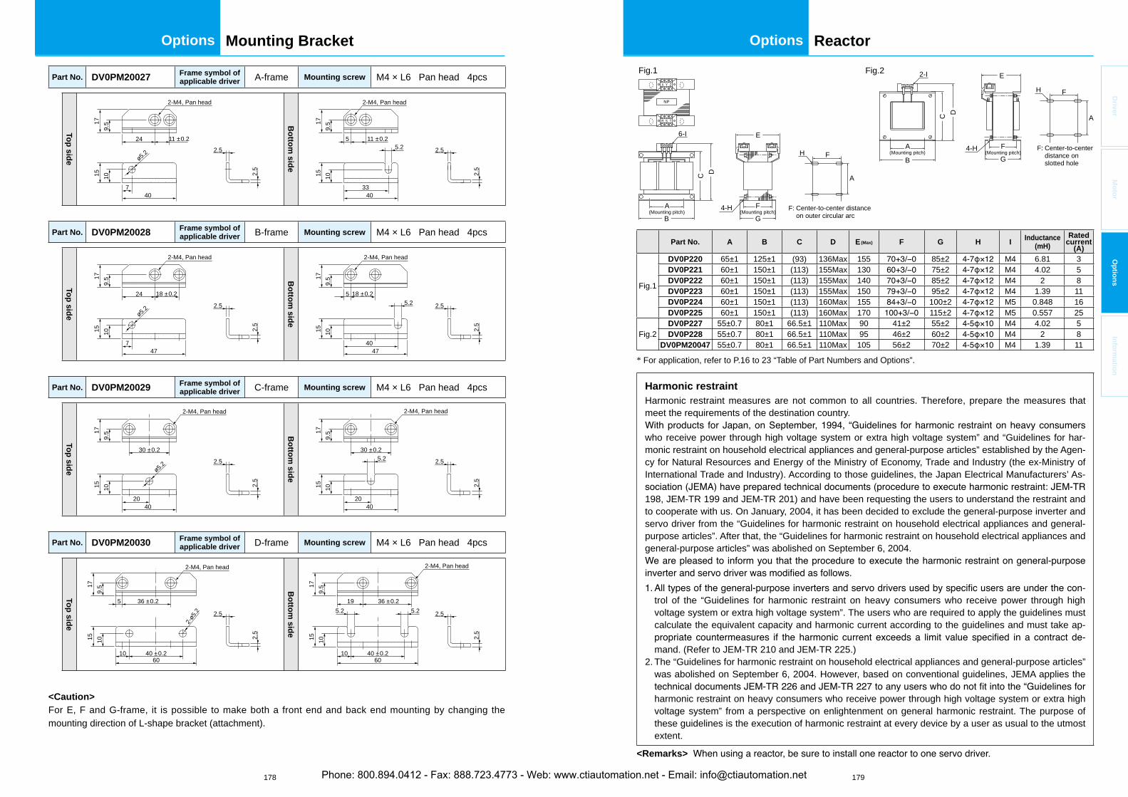
178 179
OptionsOptions
Driver
Mo
tor
Op
tion
sIn
form
ation
Reactor
Part No. A B C D E(Max) F G H I Inductance(mH)
Ratedcurrent
(A)
Fig.1
DV0P220 65±1 125±1 (93) 136Max 155 85±2 M4 6.81 3DV0P221 60±1 150±1 (113) 155Max 130 75±2 M4 4.02 5DV0P222 60±1 150±1 (113) 155Max 140 85±2 M4 2 8DV0P223 60±1 150±1 (113) 155Max 150 95±2 M4 1.39 11DV0P224 60±1 150±1 (113) 160Max 155 100±2 M5 0.848 16DV0P225 60±1 150±1 (113) 160Max 170 115±2 M5 0.557 25
Fig.2DV0P227 55±0.7 80±1 66.5±1 110Max 90 41±2 55±2 M4 4.02 5DV0P228 55±0.7 80±1 66.5±1 110Max 95 46±2 60±2 M4 2 8
DV0PM20047 55±0.7 80±1 66.5±1 110Max 105 56±2 70±2 M4 1.39 11
* For application, refer to P.16 to 23 “Table of Part Numbers and Options”.
Harmonic restraint Harmonic restraint measures are not common to all countries. Therefore, prepare the measures that meet the requirements of the destination country.
who receive power through high voltage system or extra high voltage system” and “Guidelines for har-monic restraint on household electrical appliances and general-purpose articles” established by the Agen-cy for Natural Resources and Energy of the Ministry of Economy, Trade and Industry (the ex-Ministry of International Trade and Industry). According to those guidelines, the Japan Electrical Manufacturers’ As-
198, JEM-TR 199 and JEM-TR 201) and have been requesting the users to understand the restraint and to cooperate with us. On January, 2004, it has been decided to exclude the general-purpose inverter and servo driver from the “Guidelines for harmonic restraint on household electrical appliances and general-purpose articles”. After that, the “Guidelines for harmonic restraint on household electrical appliances and general-purpose articles” was abolished on September 6, 2004.
-trol of the “Guidelines for harmonic restraint on heavy consumers who receive power through high voltage system or extra high voltage system”. The users who are required to apply the guidelines must calculate the equivalent capacity and harmonic current according to the guidelines and must take ap-
-mand. (Refer to JEM-TR 210 and JEM-TR 225.)
2. The “Guidelines for harmonic restraint on household electrical appliances and general-purpose articles” was abolished on September 6, 2004. However, based on conventional guidelines, JEMA applies the
harmonic restraint on heavy consumers who receive power through high voltage system or extra high voltage system” from a perspective on enlightenment on general harmonic restraint. The purpose of these guidelines is the execution of harmonic restraint at every device by a user as usual to the utmost extent.
<Remarks>
C
B
A(Mounting pitch)
A
A
D
6-I
R S T
NP
X Y Z
B
C D
2-I
G4-H
H
E
H
G4-H
EFig.1 Fig.2
F(Mounting pitch)
F
F: Center-to-center distance on outer circular arc
F: Center-to-center distance on slotted hole
F(Mounting pitch)
F
A(Mounting pitch)
Part No. DV0PM20027 Frame symbol of applicable driver A-frame Mounting screw M4 × L6 Pan head 4pcs
Top
side
2-M4, Pan head17
9.5
15 10
24
407
11 ±0.2
2.5
2.5
ø5.2
Bo
ttom
side
2-M4, Pan head
11 ±0.25.2
5
4033
179.
515 10
2.5
2.5
Part No. DV0PM20028 Frame symbol of applicable driver B-frame Mounting screw M4 × L6 Pan head 4pcs
Top
side
477
15 10
2.5
2.5
2-M4, Pan head
24 18 ±0.2
ø5.2
179.
5 Bo
ttom
side
4740
179.
5
2.5
2.5
15 10
5 18 ±0.2
2-M4, Pan head
5.2
Part No. DV0PM20029 Frame symbol of applicable driver C-frame Mounting screw M4 × L6 Pan head 4pcs
Top
side
30 ±0.2
15 10
2.5
2.5
2-M4, Pan head
179.
5
4020
ø5.2
Bo
ttom
side
179.
5
2.5
2.5
15 10
30 ±0.2
2-M4, Pan head
4020
5.2
Part No. DV0PM20030 Frame symbol of applicable driver D-frame Mounting screw M4 × L6 Pan head 4pcs
Top
side
36 ±0.25
15 10
2.5
10 40 ±0.260
2.5
2-M4, Pan head
179.
5
2-ø5.2
Bo
ttom
side
179.
5
2.5
2.5
10 40 ±0.260
36 ±0.219
15 10
2-M4, Pan head
5.25.2
<Caution>For E, F and G-frame, it is possible to make both a front end and back end mounting by changing the mounting direction of L-shape bracket (attachment).
Mounting Bracket
Phone: 800.894.0412 - Fax: 888.723.4773 - Web: www.ctiautomation.net - Email: [email protected]
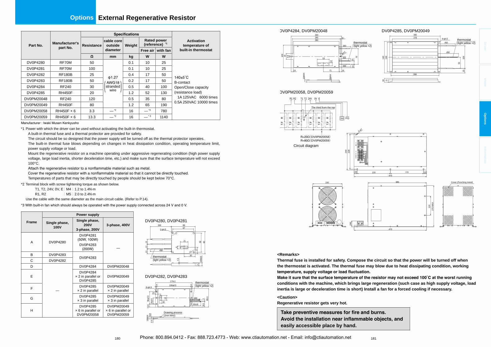
180 181
Options
Driver
Mo
tor
Op
tion
sIn
form
ation
External Regenerative Resistor
<Remarks>Thermal fuse is installed for safety. Compose the circuit so that the power will be turned off when the thermostat is activated. The thermal fuse may blow due to heat dissipating condition, working
conditions with the machine, which brings large regeneration (such case as high supply voltage, load inertia is large or deceleration time is short) Install a fan for a forced cooling if necessary.
<Caution>Regenerative resistor gets very hot.
easily accessible place by hand.
DV0P4280, DV0P4281
DV0P4282, DV0P4283
60
30
17
21
8
1313
13
710
MAX
300
Drawing process
thermostat(light yellow ×2)
(2mm MAX)
10M
AX
7
10
23
170±1
160
28
24
±1
300±30
thermostat(light yellow ×2)
Part No.Manufacturer's
part No.
Activationtemperature of
built-in thermostatResistance
cable coreoutside
diameterWeight
Rated power(reference) *1
Free air with fan
mm kg W W
DV0P4280 RF70M 50
stranded( wire )
0.1 10 25
B-contactOpen/Close capacity(resistance load) 1A 125VAC 6000 times0.5A 250VAC 10000 times
DV0P4281 RF70M 100 0.1 10 25DV0P4282 RF180B 25 0.4 17 50DV0P4283 RF180B 50 0.2 17 50DV0P4284 RF240 30 0.5 40 100DV0P4285 RH450F 20 1.2 52 130
DV0PM20048 RF240 120 0.5 35 80DV0PM20049 RH450F 80 1.2 65 190DV0PM20058 RH450F × 6 3.3 — *2 16 — *3 780DV0PM20059 RH450F × 6 13.3 — *2 16 — * 3 1140
*1 Power with which the driver can be used without activating the built-in thermostat.A built-in thermal fuse and a thermal protector are provided for safety.The circuit should be so designed that the power supply will be turned off as the thermal protector operates.The built-in thermal fuse blows depending on changes in heat dissipation condition, operating temperature limit, power supply voltage or load.Mount the regenerative resistor on a machine operating under aggressive regenerating condition (high power supply voltage, large load inertia, shorter deceleration time, etc.) and make sure that the surface temperature will not exceed 100°C.
Temperatures of parts that may be directly touched by people should be kept below 70°C.*2 Terminal block with screw tightening torque as shown below. T1, T2, 24V, 0V, E:M4:1.2 to 1.4N·m R1, R2 :M5:2.0 to 2.4N·m
Use the cable with the same diameter as the main circuit cable. (Refer to P.14).
Frame
Power supply
Single phase, 100V
Single phase, 200V
3-phase, 200V3-phase, 400V
A DV0P4280
DV0P4281
DV0P4283—
B DV0P4283DV0P4283
C DV0P4282D
—
DV0P4284 DV0PM20048
EDV0P4284
× 2 in parallel orDV0P4285
DV0PM20049
F DV0P4285× 2 in parallel
DV0PM20049× 2 in parallel
G DV0P4285× 3 in parallel
DV0PM20049× 3 in parallel
HDV0P4285
× 6 in parallel orDV0PM20058
DV0PM20049× 6 in parallel orDV0PM20059
DV0P4284, DV0PM20048 DV0P4285, DV0PM20049
300
10M
AX
9MAX
1515
300
100
25
10 71 10
14
53 70
(5)
4.5
290280
450
300
450
450
300
50
2010
0
111814
0
278
130
288
thermostat(light yellow ×2)thermostat
(light yellow ×2)
DV0PM20058, DV0PM20059
(DV0PM20058)(DV0PM20059)
Cover (Punching metal)
270
MAX
470
21520 215 20470
240
228
380193
(38)
Circuit diagram
124
6- 7
R R R R R R FAN FG
R1 R2 T1 T2 24V 0V E
T.F
T.F
T.F
T.F
T.F
T.F
The third from the top
Phone: 800.894.0412 - Fax: 888.723.4773 - Web: www.ctiautomation.net - Email: [email protected]
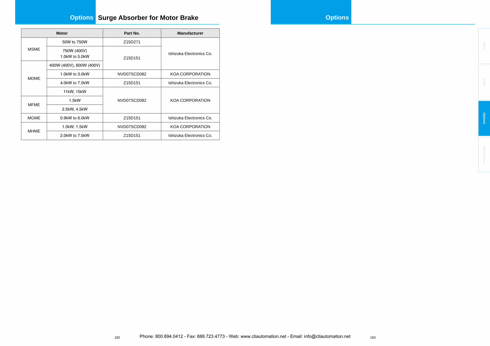
182 183
OptionsOptions
Driver
Mo
tor
Op
tion
sIn
form
ation
Surge Absorber for Motor Brake
Motor Part No. Manufacturer
MSMEZ15D271
Ishizuka Electronics Co. to Z15D151
MDME to NVD07SCD082 KOA CORPORATION
to Z15D151 Ishizuka Electronics Co.
NVD07SCD082 KOA CORPORATIONMFME
MGME to Z15D151 Ishizuka Electronics Co.
MHMENVD07SCD082 KOA CORPORATION
to Z15D151 Ishizuka Electronics Co.
Phone: 800.894.0412 - Fax: 888.723.4773 - Web: www.ctiautomation.net - Email: [email protected]

184
MEMO
Phone: 800.894.0412 - Fax: 888.723.4773 - Web: www.ctiautomation.net - Email: [email protected]
F1
Driver
Mo
tor
Op
tion
sIn
form
ation
Information
Contents
Setup support software “PANATERM”....................................................................... F2
Motor capacity selection software
AC servo motor capacity selection software .......................................................... F3
Option selection software for AC servo motor ....................................................... F3
Guide to the International System of Units (SI) ........................................................ F4
Selecting Motor Capacity .......................................................................................... F6
Request Sheet for Motor Selection ......................................................................... F12
Connection between Driver and Controller ............................................................. F20
Replacing old model servo driver with MINAS A5 series ..................................... F25
Index (Alphabetical order) ...................................................................................... F29
............................................................................................................ F44
Phone: 800.894.0412 - Fax: 888.723.4773 - Web: www.ctiautomation.net - Email: [email protected]
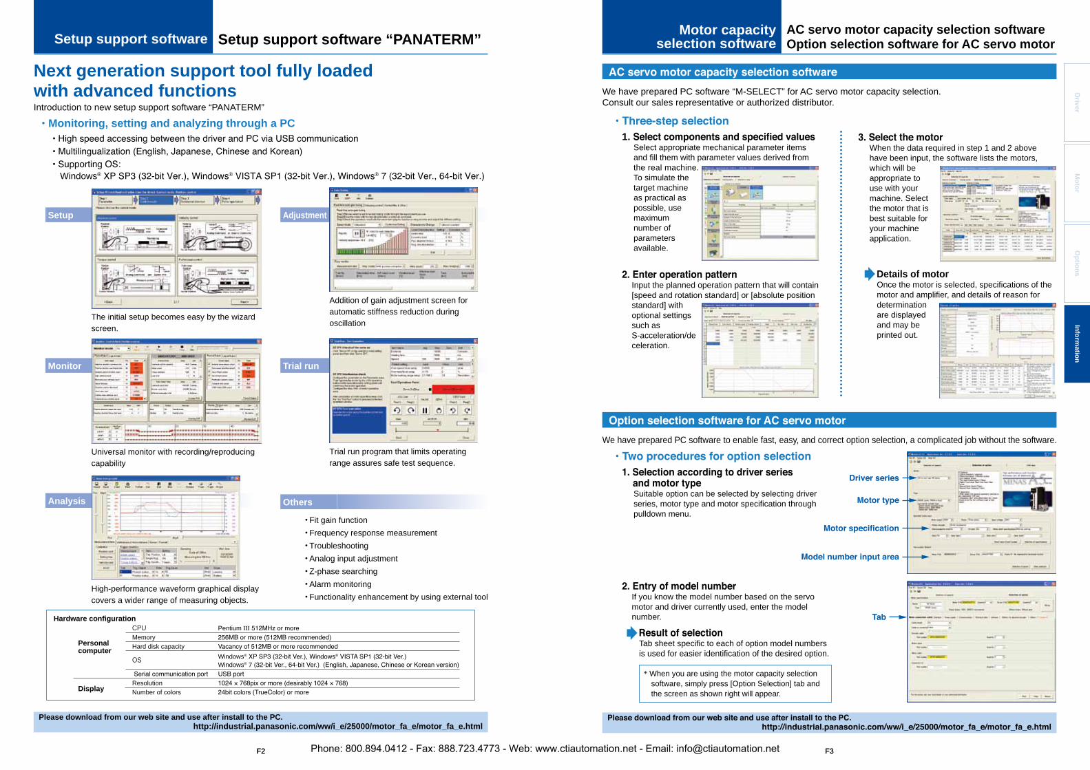
F2 F3
Hardware configuration
Setup Adjustment
Monitor Trial run
OthersAnalysis
Personalcomputer
Display
Please download from our web site and use after install to the PC.http://industrial.panasonic.com/ww/i_e/25000/motor_fa_e/motor_fa_e.html
The initial setup becomes easy by the wizard screen.
Addition of gain adjustment screen for automatic stiffness reduction during oscillation
Universal monitor with recording/reproducing capability
High-performance waveform graphical display covers a wider range of measuring objects.
Trial run program that limits operating range assures safe test sequence.
• Fit gain function• Frequency response measurement• Troubleshooting• Analog input adjustment• Z-phase searching • Alarm monitoring• Functionality enhancement by using external tool
Introduction to new setup support software “PANATERM”
Monitoring, setting and analyzing through a PC
Windows® ® ®
Next generation support tool fully loaded with advanced functions
CPUMemoryHard disk capacity
OS
ResolutionNumber of colors
Pentium
Windows® ®
Windows®
Setup support software “PANATERM”AC servo motor capacity selection softwareOption selection software for AC servo motorSetup support software
Motor capacityselection software
F2 F3
Details of motorOnce the motor is selected, specifications of the motor and amplifier, and details of reason for determinationare displayed and may be printed out.
We have prepared PC software to enable fast, easy, and correct option selection, a complicated job without the software.
Suitable option can be selected by selecting driver series, motor type and motor specification through pulldown menu.
If you know the model number based on the servo motor and driver currently used, enter the model number.
Tab sheet specific to each of option model numbers is used for easier identification of the desired option.
* When you are using the motor capacity selection software, simply press [Option Selection] tab and the screen as shown right will appear.
We have prepared PC software “M-SELECT” for AC servo motor capacity selection. Consult our sales representative or authorized distributor.
1.Select appropriate mechanical parameter items and fill them with parameter values derived from the real machine. To simulate the target machine as practical as possible, use maximumnumber of parametersavailable.
When the data required in step 1 and 2 above have been input, the software lists the motors, which will be appropriate to use with your machine. Select the motor that is best suitable for your machine application.
Input the planned operation pattern that will contain [speed and rotation standard] or [absolute position standard] with optional settings such as S-acceleration/deceleration.
Mo
tor
Op
tion
sD
riverIn
form
ation
Phone: 800.894.0412 - Fax: 888.723.4773 - Web: www.ctiautomation.net - Email: [email protected]
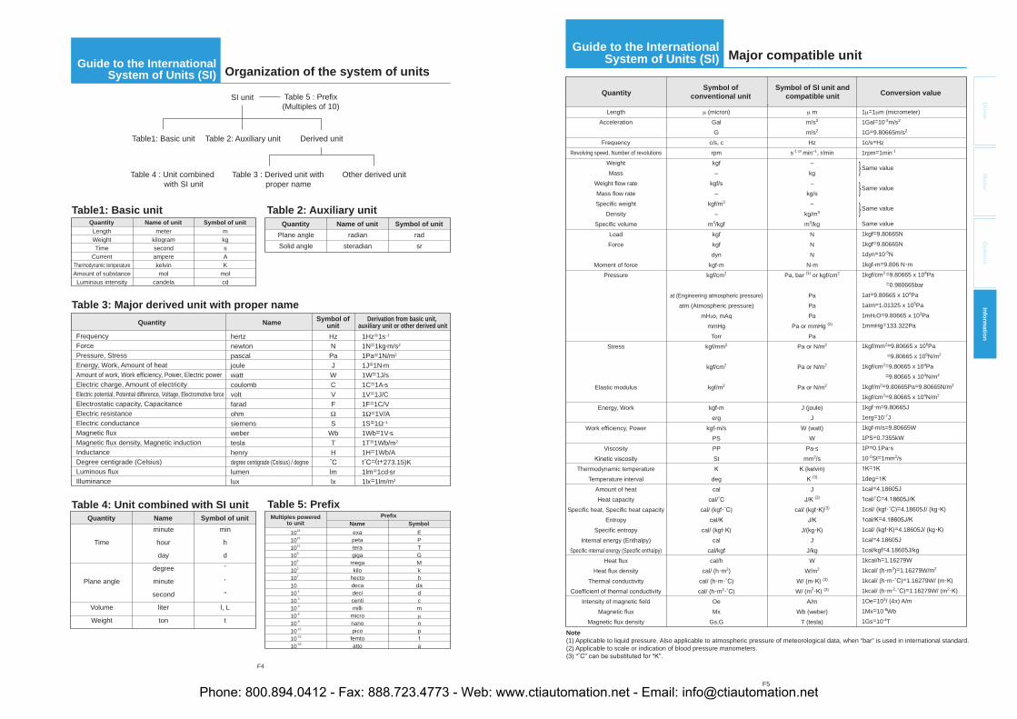
F4
SI unit
Table1: Basic unit Table 2: Auxiliary unit
Table 3 : Derived unit with proper name
Table 4 : Unit combined with SI unit
Table 5 : Prefix(Multiples of 10)
Other derived unit
Derived unit
Table1: Basic unit
LengthWeightTime
CurrentThermodynamic temperatureAmount of substanceLuminous intensity
meterkilogramsecondamperekelvinmol
candela
mkgsAK
molcd
Quantity Name of unit Symbol of unit
Table 2: Auxiliary unitQuantity
Plane angleSolid angle
Name of unitradian
steradian
Symbol of unitradsr
Table 3: Major derived unit with proper nameQuantity Name Symbol of
unitDerivation from basic unit,
auxiliary unit or other derived unitFrequencyForcePressure, StressEnergy, Work, Amount of heatAmount of work, Work efficiency, Power, Electric powerElectric charge, Amount of electricityElectric potential, Potential difference, Voltage, Electromotive forceElectrostatic capacity, CapacitanceElectric resistanceElectric conductanceMagnetic fluxMagnetic flux density, Magnetic inductionInductanceDegree centigrade (Celsius)Luminous fluxIlluminance
hertznewtonpascaljoulewattcoulombvoltfaradohmsiemensweberteslahenrydegree centigrade (Celsius) / degreelumenlux
1Hz=1s–1
1N=1kg m/s2
1Pa=1N/m2
1J=1N m1W=1J/s1C=1A s1V=1J/C1F=1C/V1 =1V/A1S=1 –1
1Wb=1V s1T=1Wb/m2
1H=1Wb/A=(t+273.15)K
1lm=1cd sr1lx=1lm/m2
HzNPaJWCVF
SWbTH
lmlx
Quantity
Table 4: Unit combined with SI unit
Time
Plane angle
Volume
Weight
Nameminute
hour
day
degree
minute
second
liter
ton
Symbol of unitmin
h
d
'
"
l, L
t
Multiples poweredto unit
1018
1015
1012
109
106
103
102
1010-1
10-2
10-3
10-6
10-9
10-12
10-15
10-18
Name SymbolPrefix
EPTGMkhdadcm
npfa
exapetateragiga
megakilo
hectodecadecicentimilli
micronanopico
femtoatto
Table 5: Prefix
Guide to the International System of Units (SI) Organization of the system of units
F5
Driver
Mo
tor
Op
tion
sIn
form
ation
Note (1) Applicable to liquid pressure. Also applicable to atmospheric pressure of meteorological data, when “bar” is used in international standard.(2) Applicable to scale or indication of blood pressure manometers.
Quantity
LengthAcceleration
Frequency Revolving speed, Number of revolutions
WeightMass
Weight flow rateMass flow rateSpecific weight
Density Specific volume
LoadForce
Moment of forcePressure
Stress
Elastic modulus
Energy, Work
Work efficiency, Power
Viscosity
Thermodynamic temperatureTemperature interval
Amount of heat Heat capacity
Specific heat, Specific heat capacityEntropy
Specific entropyInternal energy (Enthalpy)
Specific internal energy (Specific enthalpy)Heat flux
Heat flux densityThermal conductivity
Intensity of magnetic field Magnetic flux
Magnetic flux density
(micron)GalG
c/s, crpmkgf–
kgf/s–
kgf/m3
–m3/kgf
kgfkgfdyn
kgf-mkgf/cm2
at (Engineering atmospheric pressure)atm (Atmospheric pressure)
mH2o, mAqmmHg
Torrkgf/mm2
kgf/cm2
kgf/m2
kgf-merg
kgf-m/sPSPPSt
degcal
cal/ (kgf
cal/ (kgfcal
cal/kgfcal/h
cal/ (h m2)cal/ (h mcal/ (h m2
OeMx
Gs,G
mm/s2
m/s2
Hzs-1 or min–1, r/min
–kg–
kg/s–
kg/m3
m3/kgNNN
N-mPa, bar (1) or kgf/cm2
PaPaPa
Pa or mmHg (2)
PaPa or N/m2
Pa or N/m2
Pa or N/m2
J (joule)J
W (watt)W
Pa smm2/s
(3)
J(3)
cal/ (kgf (3)
J/(kgJ
J/kgW
W/m2
W/ (m (3)
W/ (m2 (3)
A/mWb (weber)
T (tesla)
1 =1 m (micrometer)1Gal=10-2m/s2
1G=9.80665m/s2
1c/s=Hz1rpm=1min-1
Same value
Same value
Same value
Same value1kgf=9.80665N1kgf=9.80665N1dyn=10-5N1kgf-m=9.806 N m1kgf/cm2 =9.80665 x 10⁴Pa =0.980665bar1at=9.80665 x 10⁴Pa1atm=1.01325 x 10⁵Pa1mH2O=9.80665 x 10³Pa1mmHg=133.322Pa
1kgf/mm2=9.80665 x 106Pa =9.80665 x 10⁶N/m2
1kgf/cm2=9.80665 x 104Pa =9.80665 x 10⁴N/m2
1kgf/m2=9.80665Pa=9.80665N/m2
1kgf/cm2=9.80665 x 104N/m2
1kgf m=9.80665J1erg=10-7J1kgf-m/s=9.80665W1PS=0.7355kW1P=0.1Pa s10-2St=1mm2/s
=
1deg=
1cal=4.18605J=
1cal/ (kgf =4.18605J/ (kg=
1cal/ (kgf =4.18605J/ (kg1cal=4.18605J1cal/kgf=4.18605J/kg1kcal/h=1.16279W1kcal/ (h m2)=1.16279W/m2
1kcal/ (h m =1.16279W/ (m1kcal/ (h m2 =1.16279W/ (m2
1Oe=103/ (4 ) A/m1Mx=10-8Wb1Gs=10-4T
Symbol ofconventional unit
Symbol of SI unit andcompatible unit Conversion value
Major compatible unitGuide to the International
System of Units (SI)
Phone: 800.894.0412 - Fax: 888.723.4773 - Web: www.ctiautomation.net - Email: [email protected]
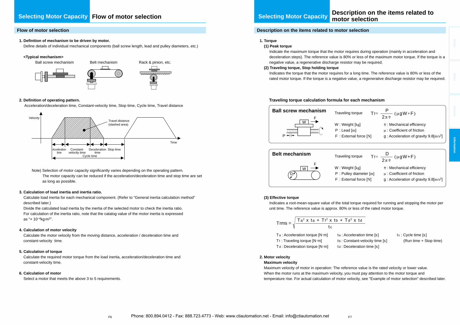
F6 F7
Driver
Mo
tor
Op
tion
sIn
form
ation
1. Definition of mechanism to be driven by motor. Define details of individual mechanical components (ball screw length, lead and pulley diameters, etc.)
<Typical mechanism> Ball screw mechanism Belt mechanism Rack & pinion, etc.
2. Definition of operating pattern. Acceleration/deceleration time, Constant-velocity time, Stop time, Cycle time, Travel distance
Note) Selection of motor capacity significantly varies depending on the operating pattern. The motor capacity can be reduced if the acceleration/deceleration time and stop time are set
as long as possible.
3. Calculation of load inertia and inertia ratio. Calculate load inertia for each mechanical component. (Refer to "General inertia calculation method"
described later.) Divide the calculated load inertia by the inertia of the selected motor to check the inertia ratio. For calculation of the inertia ratio, note that the catalog value of the motor inertia is expressed as "× 10–4kg m2".
4. Calculation of motor velocity Calculate the motor velocity from the moving distance, acceleration / deceleration time and
constant-velocity time.
5. Calculation of torque Calculate the required motor torque from the load inertia, acceleration/deceleration time and
constant-velocity time.
6. Calculation of motor Select a motor that meets the above 3 to 5 requirements.
Time
VelocityTravel distance (slashed area)
Stop timeDecelerationtime
Cycle time
Accelerationtime
Constant-velocity time
1. Torque (1) Peak torque
Indicate the maximum torque that the motor requires during operation (mainly in acceleration and deceleration steps). The reference value is 80% or less of the maximum motor torque. If the torque is a negative value, a regenerative discharge resistor may be required.
(2) Traveling torque, Stop holding torque Indicates the torque that the motor requires for a long time. The reference value is 80% or less of the rated motor torque. If the torque is a negative value, a regenerative discharge resistor may be required.
Traveling torque calculation formula for each mechanism
Ball screw mechanism
Belt mechanism
(3) Effective torqueIndicates a root-mean-square value of the total torque required for running and stopping the motor per unit time. The reference value is approx. 80% or less of the rated motor torque.
2. Motor velocity Maximum velocity
Maximum velocity of motor in operation: The reference value is the rated velocity or lower value.When the motor runs at the maximum velocity, you must pay attention to the motor torque and temperature rise. For actual calculation of motor velocity, see "Example of motor selection" described later.
Tf=2
P ( gW+F )
tc
WD
F
P
WF
Traveling torque
W : Weight [kg]P : Lead [m]F : External force [N]
: Mechanical efficiency : Coefficient of friction
g : Acceleration of gravity 9.8[m/s2]
T f=2
D ( gW+F )Traveling torque
W : Weight [kg]P : Pulley diameter [m]F : External force [N]
: Mechanical efficiency : Coefficient of friction
g : Acceleration of gravity 9.8[m/s2]
Ta2 x ta + Tf2 x tb + Td2 x tdTrms =
Ta : Acceleration torque [N m]Tf : Traveling torque [N m]Td : Deceleration torque [N m]
ta : Acceleration time [s]tb : Constant-velocity time [s]td : Deceleration time [s]
tc : Cycle time [s] (Run time + Stop time)
Selecting Motor Capacity Selecting Motor CapacityFlow of motor selection
Flow of motor selection Description on the items related to motor selection
Description on the items related to motor selection
Phone: 800.894.0412 - Fax: 888.723.4773 - Web: www.ctiautomation.net - Email: [email protected]
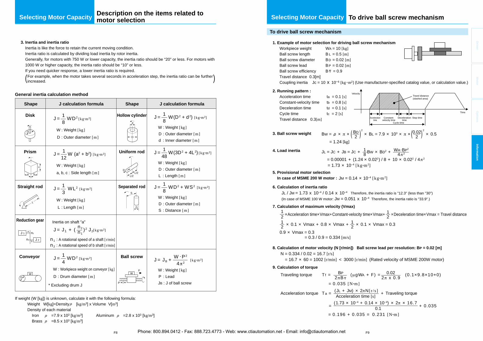
F8 F9
Driver
Mo
tor
Op
tion
sIn
form
ation= 0.00001 + (1.24 × 0.022) / 8 + 10 × 0.022 / 4 2
= 1.73 × 10⁻⁴ [kg m 2]
21
21
JL = JC + JB = JC + BW × BD2 + 81
4 2WA BP2
1. Example of motor selection for driving ball screw mechanism Workpiece weight WA = 10 [kg] Ball screw length B L = 0.5 [m] Ball screw diameter BD = 0.02 [m] Ball screw lead BP = 0.02 [m] Ball screw efficiency B = 0.9 Travel distance 0.3[m] Coupling inertia Jc = 10 x 10–6 [kg m2] (Use manufacturer-specified catalog value, or calculation value.)
2. Running pattern : Acceleration time ta = 0.1 [s] Constant-velocity time tb = 0.8 [s] Deceleration time td = 0.1 [s] Cycle time tc = 2 [s] Travel distance 0.3[m]
3. Ball screw weight
4. Load inertia
5. Provisional motor selection In case of MSME 200 W motor :
6. Calculation of inertia ratio
7. Calculation of maximum velocity (Vmax)
8. Calculation of motor velocity (N [r/min]) Ball screw lead per resolution: BP = 0.02 [m]
9. Calculation of torque
BW = × ×2
× BL = 7.9 × 10³ × ×2
× 0.5 = 1.24 [kg]
2BD
20.02
JL / JM = 1.73 x 10⁻⁴ / 0.14 x 10⁻⁴ Therefore, the inertia ratio is "12.3" (less than "30")(In case of MSME 100 W motor: JM = 0.051 x 10⁻⁴ Therefore, the inertia ratio is "33.9".)
×Acceleration time×Vmax+Constant-velocity time×Vmax+ ×Deceleration time×Vmax = Travel distance
21
21× 0.1 × Vmax + 0.8 × Vmax + × 0.1 × Vmax = 0.3
0.9 × Vmax = 0.3= 0.3 / 0.9 = 0.334 [m/s]
N = 0.334 / 0.02 = 16.7 [r/s]= 16.7 × 60 = 1002 [r/min] < 3000 [r/min] (Rated velocity of MSME 200W motor)
Traveling torque Tf = ( gWA + F) = (0.1×9.8×10+0)
= 0.035 [N m]2 B
BP2 x 0.9
0.02
Acceleration torque Ta = + Traveling torque
= + 0.035
= 0.196 + 0.035 = 0.231 [N m]
Acceleration time [s](JL + JM) × 2 N [ r /s]
0.1(1.73 × 10⁻⁴ + 0.14 × 10–4) × 2 × 16.7
Time
VelocityTravel distance (slashed area)
Stop timeDecelerationtime
Cycle time
Accelerationtime
Constant-velocity time
JM = 0.14 × 10⁻⁴ [kg m 2]
J = J1 + ( ) 2 J2
3. Inertia and inertia ratioInertia is like the force to retain the current moving condition. Inertia ratio is calculated by dividing load inertia by rotor inertia. Generally, for motors with 750 W or lower capacity, the inertia ratio should be “20” or less. For motors with 1000 W or higher capacity, the inertia ratio should be “10” or less. If you need quicker response, a lower inertia ratio is required. For example, when the motor takes several seconds in acceleration step, the inertia ratio can be further increased.
J =81 WD2 [kg m2]
J =121 W (a2 + b2) [kg m2]
J =81 W(D2 + d2) [kg m2]
n2n1
J =41 WD2 [kg m2]
W : Weight [kg]
D : Outer diameter [m]
W : Weight [kg]D : Outer diameter [m]d : Inner diameter [m]
J =81 WD2 + WS2 [kg m2]
W : Weight [kg]D : Outer diameter [m]S : Distance [m]
J = JB +4 2
W P2[kg m2]
W : Weight [kg]P : LeadJB : J of ball screw
J =481 W(3D2 + 4L2) [kg m2]
W : Weight [kg]D : Outer diameter [m]L : Length [m]
Shape
General inertia calculation method
Disk
J calculation formula Shape J calculation formula
W : Weight [kg]
a, b, c : Side length [m]
n1 : A rotational speed of a shaft [ r/min]n2 : A rotational speed of b shaft [ r/min]
J =31 WL2 [kg m2]
[kg m2]
W : Weight [kg]
L : Length [m]
W : Workpiece weight on conveyor [kg]
D : Drum diameter [m]
Inertia on shaft "a"
* Excluding drum J
Prism
Straight rod
Reduction gear
Conveyor
Hollow cylinder
Uniform rod
Separated rod
Ball screw
If weight (W [kg]) is unknown, calculate it with the following formula: Weight W[kg]=Density [kg/m3] x Volume V[m3] Density of each material Iron =7.9 x 10³ [kg/m3] Aluminum =2.8 x 10³ [kg/m3] Brass =8.5 x 10³ [kg/m3]
D
WD
P
WF
a b
cD
L/2L/2
aJ 1
J 2n2
n1
b
L
D
d
S
D
( )
Selecting Motor CapacityDescription on the items related to motor selection To drive ball screw mechanism Selecting Motor Capacity
To drive ball screw mechanism
Phone: 800.894.0412 - Fax: 888.723.4773 - Web: www.ctiautomation.net - Email: [email protected]
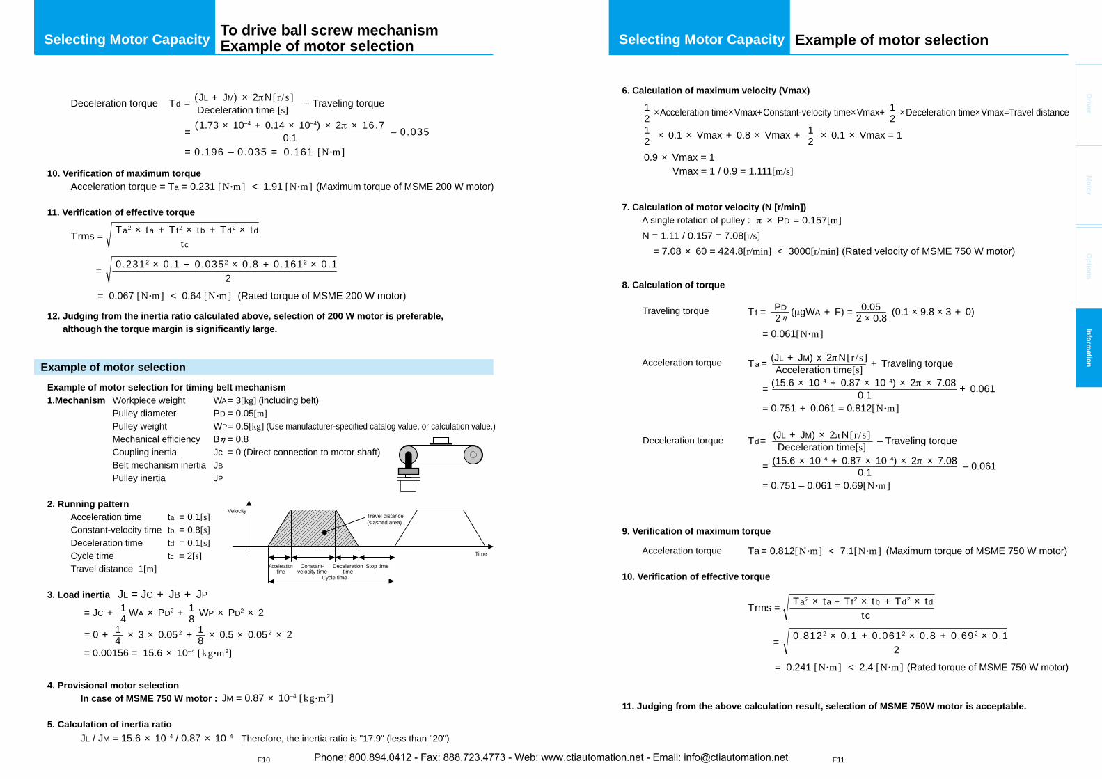
F10 F11
Driver
Mo
tor
Op
tion
sIn
form
ation
10. Verification of maximum torque
11. Verification of effective torque
12. Judging from the inertia ratio calculated above, selection of 200 W motor is preferable, although the torque margin is significantly large.
Example of motor selection for timing belt mechanism 1.Mechanism Workpiece weight WA = 3[kg] (including belt)
Pulley diameter PD = 0.05[m]Pulley weight WP = 0.5[kg] (Use manufacturer-specified catalog value, or calculation value.)Mechanical efficiency B = 0.8Coupling inertia Jc = 0 (Direct connection to motor shaft)Belt mechanism inertia JBPulley inertia JP
2. Running pattern Acceleration time ta = 0.1[s] Constant-velocity time tb = 0.8[s] Deceleration time td = 0.1[s] Cycle time tc = 2[s] Travel distance 1[m]
3. Load inertia JL = JC + JB + JP
4. Provisional motor selection In case of MSME 750 W motor :
5. Calculation of inertia ratio
Deceleration torque Td = – Traveling torque
= – 0.035
= 0.196 – 0.035 = 0.161 [N m]
Deceleration time [s](JL + JM) × 2 N [ r /s]
0.1(1.73 × 10⁻⁴ + 0.14 × 10–4) × 2 × 16.7
Acceleration torque = Ta = 0.231 [N m] < 1.91 [N m] (Maximum torque of MSME 200 W motor)
tc
Ta2 × ta + Tf2 × tb + Td2 × tdTrms =
20.2312 × 0.1 + 0.0352 × 0.8 + 0.1612 × 0.1=
= 0.067 [N m] < 0.64 [N m] (Rated torque of MSME 200 W motor)
Time
VelocityTravel distance (slashed area)
Stop timeDecelerationtime
Cycle time
Accelerationtime
Constant-velocity time
= 0 + × 3 × 0.052 + × 0.5 × 0.052 × 2
= 0.00156 = 15.6 × 10⁻⁴ [kg m 2]
= JC + WA × PD2 + WP × PD2 × 241
41
81
81
JM = 0.87 × 10⁻⁴ [kg m 2]
JL / JM = 15.6 × 10⁻⁴ / 0.87 × 10⁻⁴ Therefore, the inertia ratio is "17.9" (less than "20")
Selecting Motor Capacity Selecting Motor CapacityTo drive ball screw mechanism Example of motor selection
Example of motor selection
Example of motor selection
6. Calculation of maximum velocity (Vmax)
7. Calculation of motor velocity (N [r/min]) A single rotation of pulley :
8. Calculation of torque
Traveling torque
Acceleration torque
Deceleration torque
9. Verification of maximum torque
Acceleration torque
10. Verification of effective torque
11. Judging from the above calculation result, selection of MSME 750W motor is acceptable.
×Acceleration time×Vmax+Constant-velocity time×Vmax+ ×Deceleration time×Vmax=Travel distance
N = 1.11 / 0.157 = 7.08[r/s] = 7.08 × 60 = 424.8[r/min] < 3000[r/min] (Rated velocity of MSME 750 W motor)
21
21
× 0.1 × Vmax + 0.8 × Vmax + × 0.1 × Vmax = 121
Tf = ( gWA + F) = (0.1 × 9.8 × 3 + 0)2 × 0.80.05
2PD
21
0.9 × Vmax = 1 Vmax = 1 / 0.9 = 1.111[m/s]
= 0.061[N m]
Ta = + Traveling torque
Ta = 0.812[N m] < 7.1[N m] (Maximum torque of MSME 750 W motor)
Acceleration time[s](JL + JM) x 2 N [ r /s]
= + 0.061
= 0.751 + 0.061 = 0.812[N m]0.1
(15.6 × 10⁻⁴ + 0.87 × 10–4) × 2 × 7.08
Td= – Traveling torqueDeceleration time[s](JL + JM) × 2 N [ r /s]
= – 0.061
= 0.751 – 0.061 = 0.69[N m]0.1
(15.6 × 10⁻⁴ + 0.87 × 10–4) × 2 × 7.08
tcTa2 × ta + Tf2 × tb + Td2 × tdTrms =
20.8122 × 0.1 + 0.0612 × 0.8 + 0.692 × 0.1=
= 0.241 [N m] < 2.4 [N m] (Rated torque of MSME 750 W motor)
× PD = 0.157[m]
Phone: 800.894.0412 - Fax: 888.723.4773 - Web: www.ctiautomation.net - Email: [email protected]
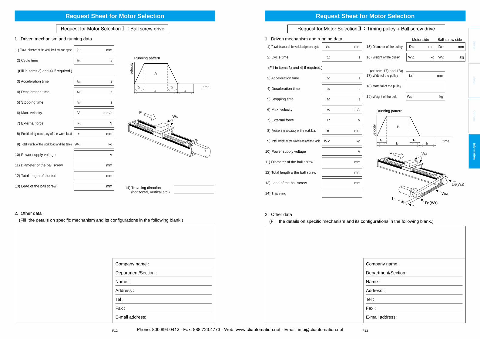
F12 F13
Driver
Mo
tor
Op
tion
sIn
form
ation
1) Travel distance of the work load per one cycle 1: mm
2) Cycle time t0: s
(Fill in items 3) and 4) if required.)
3) Acceleration time ta: s
4) Deceleration time td: s
5) Stopping time ts: s
6) Max. velocity V: mm/s
7) External force F: N
8) Positioning accuracy of the work load ± mm
9) Total weight of the work load and the table WA: kg
10) Power supply voltage V
11) Diameter of the ball screw mm
12) Total length of the ball mm
13) Lead of the ball screw mm 14) Traveling direction (horizontal, vertical etc.)
ta tdt0 ts
FWA
1. Driven mechanism and running data
2. Other data(Fill the details on specific mechanism and its configurations in the following blank.)
Running pattern
time
velo
city
Company name :
Department/Section :
Name :
Address :
Tel :
Fax :
E-mail address:
1
Request Sheet for Motor Selection
1) Travel distance of the work load per one cycle 1: mm
2) Cycle time t0: s
(Fill in items 3) and 4) if required.)
3) Acceleration time ta: s
4) Deceleration time td: s
5) Stopping time ts: s
6) Max. velocity V: mm/s
7) External force F: N
8) Positioning accuracy of the work load ± mm
9) Total weight of the work load and the table WA: kg
10) Power supply voltage V
11) Diameter of the ball screw mm
12) Total length o the ball screw mm
13) Lead of the ball screw mm
14) Traveling
ta tdt0 ts
F WA
D2(W2)
D1(W1)
WM
L1
15) Diameter of the pulley D1: mm D2: mm
16) Weight of the pulley W1: kg W2: kg
17) Width of the pulley L1: mm
18) Material of the pulley
19) Weight of the belt WM: kg
(or item 17) and 18))
Motor side Ball screw side1. Driven mechanism and running data
2. Other data(Fill the details on specific mechanism and its configurations in the following blank.)
Running pattern
time
velo
city
Company name :
Department/Section :
Name :
Address :
Tel :
Fax :
E-mail address:
1
Request Sheet for Motor Selection
Phone: 800.894.0412 - Fax: 888.723.4773 - Web: www.ctiautomation.net - Email: [email protected]
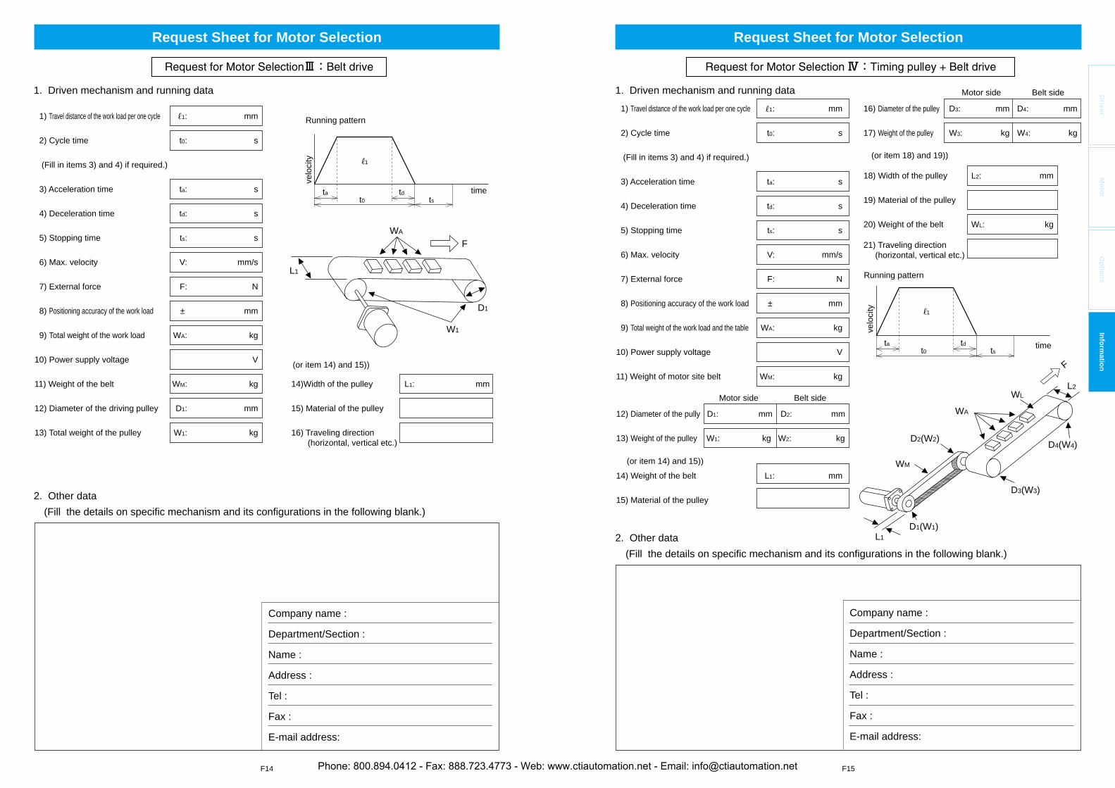
F14 F15
Driver
Mo
tor
Op
tion
sIn
form
ation
1) Travel distance of the work load per one cycle 1: mm
2) Cycle time t0: s
(Fill in items 3) and 4) if required.)
3) Acceleration time ta: s
4) Deceleration time td: s
5) Stopping time ts: s
6) Max. velocity V: mm/s
7) External force F: N
8) Positioning accuracy of the work load ± mm
9) Total weight of the work load WA: kg
10) Power supply voltage V
11) Weight of the belt WM: kg
12) Diameter of the driving pulley D1: mm
13) Total weight of the pulley W1: kg
1. Driven mechanism and running data
14)Width of the pulley L1: mm
15) Material of the pulley
16) Traveling direction (horizontal, vertical etc.)
ta tdt0 ts
FWA
W1
L1
D1
(or item 14) and 15))
2. Other data(Fill the details on specific mechanism and its configurations in the following blank.)
Company name :
Department/Section :
Name :
Address :
Tel :
Fax :
E-mail address:
Running pattern
time
velo
city 1
Request Sheet for Motor Selection
ta tdt0 ts
1) Travel distance of the work load per one cycle 1: mm
2) Cycle time t0: s
(Fill in items 3) and 4) if required.)
3) Acceleration time ta: s
4) Deceleration time td: s
5) Stopping time ts: s
6) Max. velocity V: mm/s
7) External force F: N
8) Positioning accuracy of the work load ± mm
9) Total weight of the work load and the table WA: kg
10) Power supply voltage V
11) Weight of motor site belt WM: kg
12) Diameter of the pully D1: mm D2: mm
13) Weight of the pulley W1: kg W2: kg
14) Weight of the belt L1: mm
15) Material of the pulley
1. Driven mechanism and running data16) Diameter of the pulley D3: mm D4: mm
17) Weight of the pulley W3: kg W4: kg
18) Width of the pulley L2: mm
19) Material of the pulley
20) Weight of the belt WL: kg
21) Traveling direction (horizontal, vertical etc.)
(or item 18) and 19))
Motor side Belt side
Motor side Belt side
L1
L2
WM
WL
WA
D2(W2)
D3(W3)
D4(W4)
F
D1(W1)
(or item 14) and 15))
Running pattern
time
velo
city
2. Other data(Fill the details on specific mechanism and its configurations in the following blank.)
Company name :
Department/Section :
Name :
Address :
Tel :
Fax :
E-mail address:
1
Request Sheet for Motor Selection
Phone: 800.894.0412 - Fax: 888.723.4773 - Web: www.ctiautomation.net - Email: [email protected]
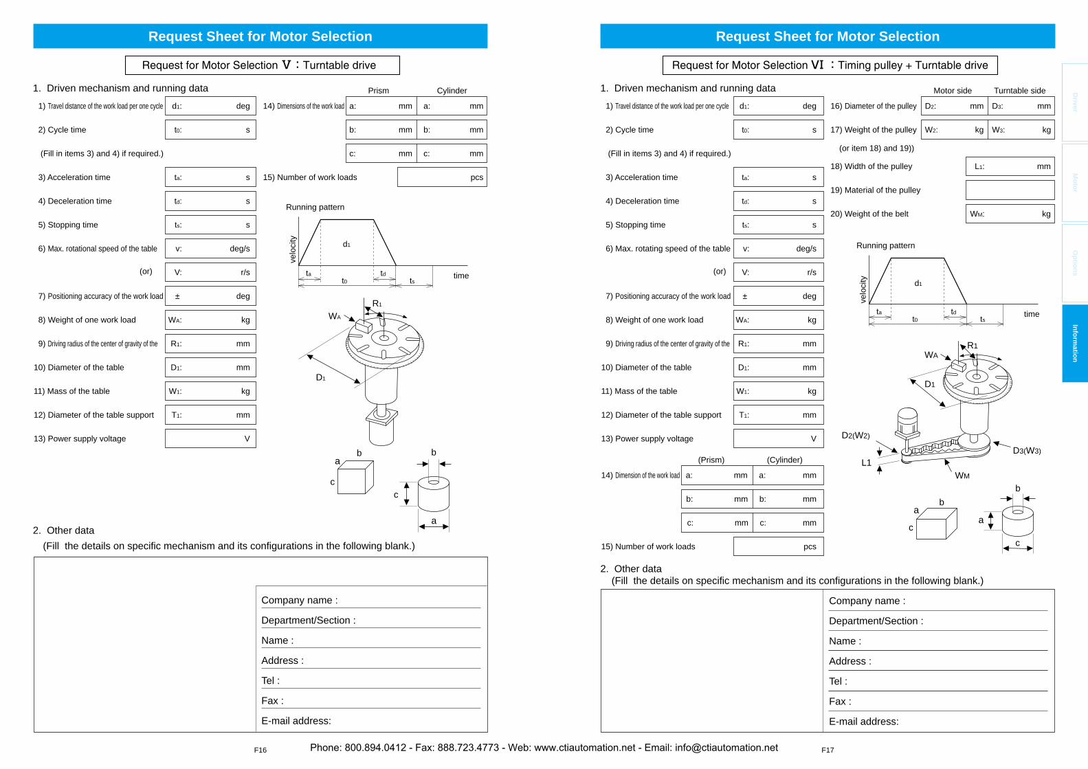
F16 F17
Driver
Mo
tor
Op
tion
sIn
form
ation
D1
b b
cc
a
a
WA
R1
ta tdt0 ts
1) Travel distance of the work load per one cycle d1: deg
2) Cycle time t0: s
(Fill in items 3) and 4) if required.)
3) Acceleration time ta: s
4) Deceleration time td: s
5) Stopping time ts: s
6) Max. rotational speed of the table v: deg/s
V: r/s
7) Positioning accuracy of the work load ± deg
8) Weight of one work load WA: kg
9) Driving radius of the center of gravity of the R1: mm
10) Diameter of the table D1: mm
11) Mass of the table W1: kg
12) Diameter of the table support T1: mm
13) Power supply voltage V
14) Dimensions of the work load a: mm a: mm
b: mm b: mm
c: mm c: mm
15) Number of work loads pcs
(or)
Prism Cylinder
d1
1. Driven mechanism and running data
Running pattern
time
velo
city
2. Other data(Fill the details on specific mechanism and its configurations in the following blank.)
Company name :
Department/Section :
Name :
Address :
Tel :
Fax :
E-mail address:
Request Sheet for Motor Selection
Running pattern
time
velo
city
ta tdt0 ts
1) Travel distance of the work load per one cycle d1: deg
2) Cycle time t0: s
(Fill in items 3) and 4) if required.)
3) Acceleration time ta: s
4) Deceleration time td: s
5) Stopping time ts: s
6) Max. rotating speed of the table v: deg/s
V: r/s
7) Positioning accuracy of the work load ± deg
8) Weight of one work load WA: kg
9) Driving radius of the center of gravity of the R1: mm
10) Diameter of the table D1: mm
11) Mass of the table W1: kg
12) Diameter of the table support T1: mm
13) Power supply voltage V
14) Dimension of the work load a: mm a: mm
b: mm b: mm
c: mm c: mm
15) Number of work loads pcs
1. Driven mechanism and running data
2. Other data (Fill the details on specific mechanism and its configurations in the following blank.)
16) Diameter of the pulley D2: mm D3: mm
17) Weight of the pulley W2: kg W3: kg
18) Width of the pulley L1: mm
19) Material of the pulley
20) Weight of the belt WM: kg
(or)
(Prism) (Cylinder)
Motor side
(or item 18) and 19))
Turntable side
bb
cc
WA
D1
L1WM
D2(W2)
R1
D3(W3)
aa
Company name :
Department/Section :
Name :
Address :
Tel :
Fax :
E-mail address:
d1
Request Sheet for Motor Selection
Phone: 800.894.0412 - Fax: 888.723.4773 - Web: www.ctiautomation.net - Email: [email protected]
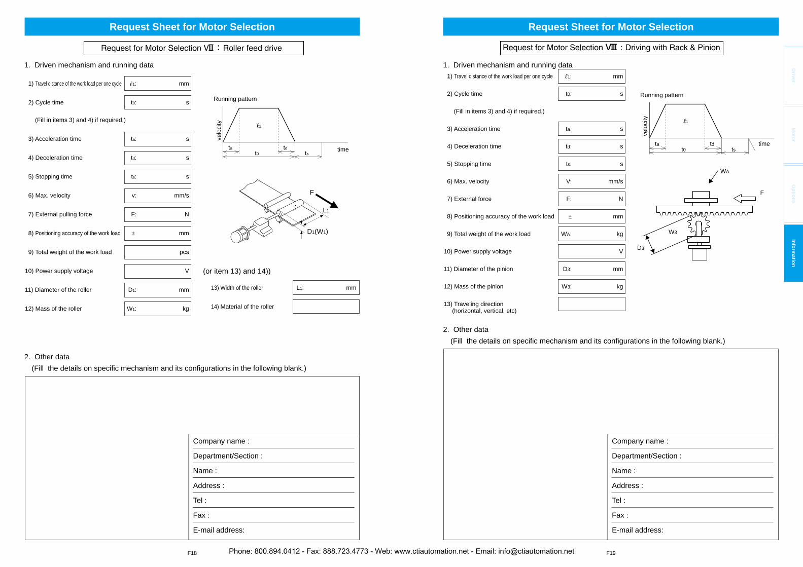
F18 F19
Driver
Mo
tor
Op
tion
sIn
form
ation
1) Travel distance of the work load per one cycle 1: mm
2) Cycle time t0: s
(Fill in items 3) and 4) if required.)
3) Acceleration time ta: s
4) Deceleration time td: s
5) Stopping time ts: s
6) Max. velocity v: mm/s
7) External pulling force F: N
8) Positioning accuracy of the work load ± mm
9) Total weight of the work load pcs
10) Power supply voltage V
11) Diameter of the roller D1: mm
12) Mass of the roller W1: kg
1. Driven mechanism and running data
2. Other data(Fill the details on specific mechanism and its configurations in the following blank.)
13) Width of the roller L1: mm
14) Material of the roller
(or item 13) and 14))
Running pattern
time
velo
city
ta tdt0 ts
F
L1
D1(W1)
Company name :
Department/Section :
Name :
Address :
Tel :
Fax :
E-mail address:
1
Request Sheet for Motor Selection
Running pattern
time
velo
city
ta tdt0 ts
1) Travel distance of the work load per one cycle 1: mm
2) Cycle time t0: s
(Fill in items 3) and 4) if required.)
3) Acceleration time ta: s
4) Deceleration time td: s
5) Stopping time ts: s
6) Max. velocity V: mm/s
7) External force F: N
8) Positioning accuracy of the work load ± mm
9) Total weight of the work load WA: kg
10) Power supply voltage V
11) Diameter of the pinion D3: mm
12) Mass of the pinion W3: kg
13) Traveling direction (horizontal, vertical, etc)
1. Driven mechanism and running data
2. Other data(Fill the details on specific mechanism and its configurations in the following blank.)
Company name :
Department/Section :
Name :
Address :
Tel :
Fax :
E-mail address:
D3
W3
F
WA
1
Request Sheet for Motor Selection
Phone: 800.894.0412 - Fax: 888.723.4773 - Web: www.ctiautomation.net - Email: [email protected]
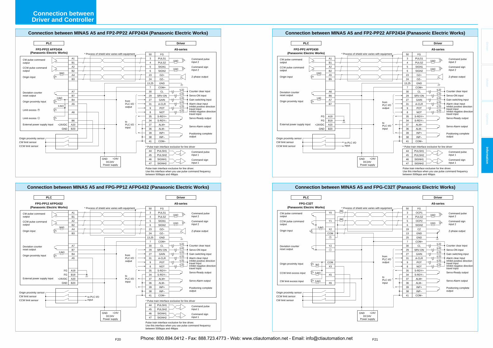
F20 F21
Driver
Mo
tor
Op
tion
sIn
form
ation
220
220
4.7
390
3.6k
6.8k
4.7
4.7
4.7
4.7
4.7
CW pulse command output
CCW pulse command output
Origin input
Deviation counter reset output
External power supply input
Origin proximity input
Limit excess +
Limit excess
Driver
A5-series
5034562324
13,257302927319835343736393841
FGPULS1PULS2SIGN1SIGN2OZ+OZGND
COM+CL
SRV-ONGAINA-CLRPOTNOT
S-RDY+S-RDYALM+ALMINP+INP
COM
* Process of shield wire varies with equipment.
+24VDCGND
* Pulse train interface exclusive for line driver
Pulse train interface exclusive for line driver. Use this interface when you use pulse command frequency between 500kpps and 4Mpps
Connection between MINAS A5 and FP2-PP22 AFP2434 (Panasonic Electric Works)
44454647
PULSH1PULSH2SIGNH1SIGNH2
PLC
FP2-PP22 AFP2434(Panasonic Electric Works)
fromPLC I/O output
toPLC I/O input
A1B1A2B2A4B3
A7B7B4A5
A6
B6A20B20
CW limit sensorOrigin proximity sensor
CCW limit sensor
CW limit sensorOrigin proximity sensor
CCW limit sensor
GND +24VDC24V
Power supply
GND +24VDC24V
Power supply
Driver
A5-series
5034562324
13,257302927319835343736393841
FGPULS1PULS2SIGN1SIGN2OZ+OZGND
COM+CL
SRV-ONGAINA-CLRPOTNOT
S-RDY+S-RDYALM+ALMINP+INP
COM
* Process of shield wire varies with equipment.
220
FGFG
+24VDCGND
* Pulse train interface exclusive for line driver
Pulse train interface exclusive for line driver. Use this interface when you use pulse command frequency between 500kpps and 4Mpps
Connection between MINAS A5 and FPG-PP12 AFPG432 (Panasonic Electric Works)
44454647
PULSH1PULSH2SIGNH1SIGNH2
PLC
FPG-PP12 AFPG432(Panasonic Electric Works)
220
4.7
560
6.8k
4.7
4.7
4.7
4.7
4.7
fromPLC I/O output
toPLC I/O input
to PLC I/O input
A1B1A2B2A4B3
A7B7B4A5
A19B19A20B20
Command pulse input 2
Counter clear inputServo-ON input
Servo-Ready output
Servo-Alarm output
Positioning complete output
Alarm clear input
Z-phase output
Command sign input 2
Command pulse input 1
Command sign input 1
Gain switching input
Inhibit negative directiontravel input
Inhibit positive direction travel input
CW pulse command output
CCW pulse command output
Origin input
Deviation counter reset output
External power supply input
Origin proximity input
Connection between Driver and Controller
Driver
A5-series
PLC
Driver
A5-series
PLC
DC24VPower supply
DC24VPower supply
Connection between MINAS A5 and FP2-PP22 AFP2434 (Panasonic Electric Works)
FP2-PP2 AFP2430(Panasonic Electric Works)
Connection between MINAS A5 and FPG-C32T (Panasonic Electric Works)
* Process of shield wire varies with equipment.
* Pulse train interface exclusive for line driver
Pulse train interface exclusive for line driver. Use this interface when you use pulse command frequency between 500kpps and 4Mpps
* Process of shield wire varies with equipment.FPG-C32T
(Panasonic Electric Works)
fromPLC I/O output
toPLC I/O input
Y0
Y1
X2COM
+
Y2
COMX3
X5
X6
503456
2324
13,257
3029273198
35343736393841
FGPULS1PULS2SIGN1SIGN2OZ+OZGND
COM+CL
SRV-ONGAIN
A-CLRPOTNOT
S-RDY+S-RDYALM+ALMINP+INP
COM
FGFG
+24VDCGND
44454647
PULSH1PULSH2SIGNH1SIGNH2
fromPLC I/O output
toPLC I/O input
to PLC I/O input
A1B1A2B2A5B5
A6B6A7B7
A19B19A20B20
2k
2k
503456
1913257
3029273198
35343736393841
FGOCP1PULS2OCP2SIGN2
CZGNDGND
COM+CL
SRV-ONGAIN
A-CLRPOTNOT
S-RDY+S-RDYALM+ALMINP+INP
COM
GND +24V
GND +24V
Command pulse input 2
Counter clear inputServo-ON input
Servo-Ready output
Servo-Alarm output
Positioning complete output
Alarm clear input
Z-phase output
Command sign input 2
Command pulse input 1
Command sign input 1
Gain switching input
Inhibit negative directiontravel input
Inhibit positive direction travel input
Command pulse input 2
Counter clear inputServo-ON input
Servo-Ready output
Servo-Alarm output
Positioning complete output
Alarm clear input
Z-phase output
Command sign input 2
Gain switching input
Inhibit negative directiontravel input
Inhibit positive direction travel input
CW limit sensorOrigin proximity sensor
CCW limit sensor
CCW limit sensorOrigin proximity sensor
CW limit sensor
CW pulse command output
CCW pulse command output
Origin input
Deviation counter reset output
External power supply input
Origin proximity input
CW pulse command output
CCW pulse command output
Origin input
Deviation counter reset output
Origin proximity input
CCW limit excess input
CW limit excess input
220
220
4.7
4.7
4.7
4.7
4.7
4.7
1.6
220
220
220
4.7
4.7
4.7
4.7
4.7
4.7
5.6k
5.6k
3k
5.6k
Phone: 800.894.0412 - Fax: 888.723.4773 - Web: www.ctiautomation.net - Email: [email protected]
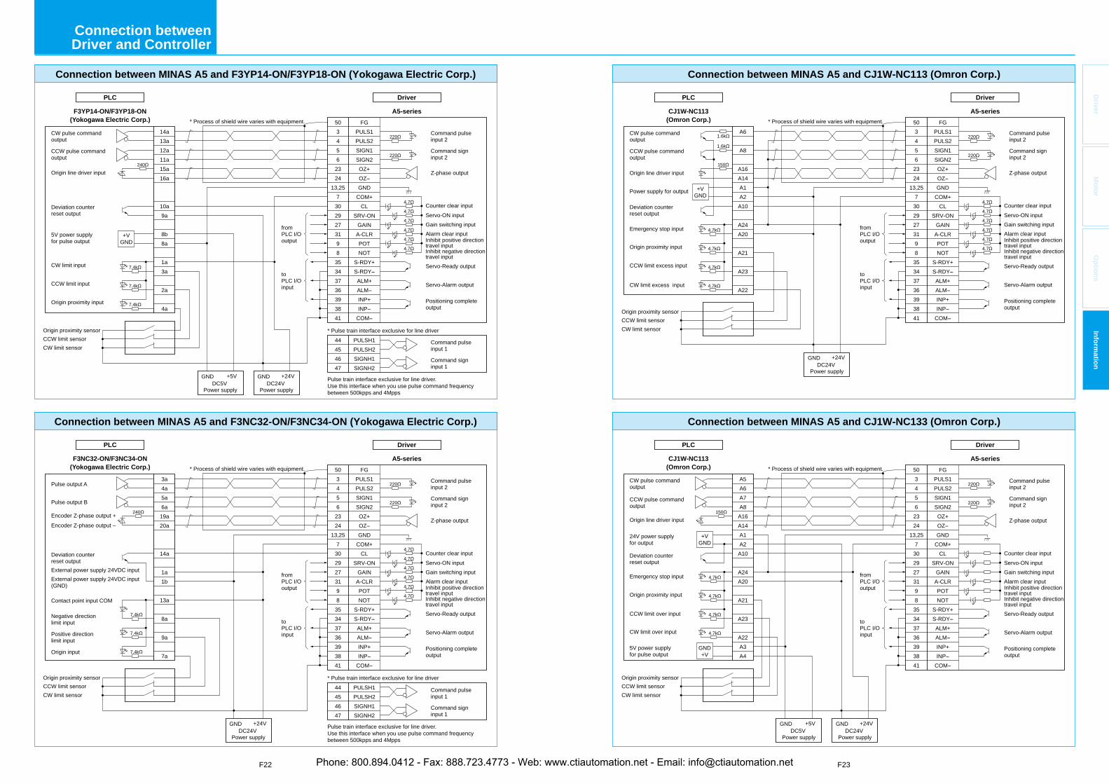
F22 F23
Driver
Mo
tor
Op
tion
sIn
form
ation
Driver
A5-series
PLC
Driver
A5-series
PLC
DC24VPower supply
DC24VPower supply
DC5VPower supply
Connection between MINAS A5 and CJ1W-NC113 (Omron Corp.)
Connection between MINAS A5 and CJ1W-NC133 (Omron Corp.)
* Process of shield wire varies with equipment.
* Process of shield wire varies with equipment.CJ1W-NC113
(Omron Corp.)
503456
2324
13,257
3029273198
35343736393841
FGPULS1PULS2SIGN1SIGN2OZ+OZGND
COM+CL
SRV-ONGAIN
A-CLRPOTNOT
S-RDY+S-RDYALM+ALMINP+INP
COM
CJ1W-NC113(Omron Corp.)
fromPLC I/O output
toPLC I/O input
A6
A8
A16A14A1A2
A10
A24A20
A21
A23
A22
CCW limit sensorOrigin proximity sensor
CW limit sensor
CCW limit sensorOrigin proximity sensor
CW limit sensor
fromPLC I/O output
toPLC I/O input
A5A6A7A8
A16A14A1A2
A10
A24A20
A21
A23
A22A3A4
503456
2324
13,257
3029273198
35343736393841
FGPULS1PULS2SIGN1SIGN2OZ+OZGND
COM+CL
SRV-ONGAIN
A-CLRPOTNOT
S-RDY+S-RDYALM+ALMINP+INP
COM
GND +24V
GND +24V
GND +5V
Command pulse input 2
Counter clear inputServo-ON input
Servo-Ready output
Servo-Alarm output
Positioning complete output
Alarm clear input
Z-phase output
Command sign input 2
Gain switching input
Inhibit negative directiontravel input
Inhibit positive direction travel input
Command pulse input 2
Counter clear inputServo-ON input
Servo-Ready output
Servo-Alarm output
Positioning complete output
Alarm clear input
Z-phase output
Command sign input 2
Gain switching input
Inhibit negative directiontravel input
Inhibit positive direction travel input
CW pulse command output
CCW pulse command output
Origin line driver input
Power supply for output
Deviation counter reset output
Emergency stop input
Origin proximity input
CCW limit excess input
CW limit excess input
CW pulse command output
CCW pulse command output
Origin line driver input
Deviation counter reset output
24V power supply for output
Emergency stop input
Origin proximity input
CCW limit over input
CW limit over input
5V power supplyfor pulse output
+VGND
220
220
4.7
1.6k
4.7
4.7
4.7
4.7
4.7
150
1.6k
4.7k
4.7k
4.7k
4.7k
4.7k
4.7k
4.7k
4.7k
150
220
220
GND+V
+VGND
Driver
A5-series
PLC
Driver
A5-series
PLC
DC24VPower supply
DC5VPower supply
DC24VPower supply
Connection between MINAS A5 and F3YP14-ON/F3YP18-ON (Yokogawa Electric Corp.)
F3YP14-ON/F3YP18-ON(Yokogawa Electric Corp.)
fromPLC I/O output
toPLC I/O input
14a13a12a11a15a16a
10a9a
8b8a
1a3a
2a
4a
5034562324
13,257302927319835343736393841
FGPULS1PULS2SIGN1SIGN2OZ+OZGND
COM+CL
SRV-ONGAINA-CLRPOTNOT
S-RDY+S-RDYALM+ALMINP+INP
COM
44454647
PULSH1PULSH2SIGNH1SIGNH2
Command pulse input 2
Counter clear inputServo-ON input
Servo-Ready output
Servo-Alarm output
Positioning complete output
Alarm clear input
Z-phase output
Command sign input 2
Command pulse input 1
Command sign input 1
Gain switching input
Inhibit negative directiontravel input
Inhibit positive direction travel input
Command pulse input 2
Counter clear inputServo-ON input
Servo-Ready output
Servo-Alarm output
Positioning complete output
Alarm clear input
Z-phase output
Command sign input 2
Command pulse input 1
Command sign input 1
Gain switching input
Inhibit negative directiontravel input
Inhibit positive direction travel input
Connection between MINAS A5 and F3NC32-ON/F3NC34-ON (Yokogawa Electric Corp.)
F3NC32-ON/F3NC34-ON(Yokogawa Electric Corp.)
fromPLC I/O output
toPLC I/O input
3a4a5a6a19a20a
14a
1a1b
13a
8a
9a
7a
5034562324
13,257302927319835343736393841
FGPULS1PULS2SIGN1SIGN2OZ+OZGND
COM+CL
SRV-ONGAINA-CLRPOTNOT
S-RDY+S-RDYALM+ALMINP+INP
COM
44454647
PULSH1PULSH2SIGNH1SIGNH2
* Process of shield wire varies with equipment.
* Pulse train interface exclusive for line driver
Pulse train interface exclusive for line driver. Use this interface when you use pulse command frequency between 500kpps and 4Mpps
* Process of shield wire varies with equipment.
* Pulse train interface exclusive for line driver
Pulse train interface exclusive for line driver. Use this interface when you use pulse command frequency between 500kpps and 4Mpps
GND +24VGND +5V
GND +24V
CCW limit sensorOrigin proximity sensor
CW limit sensor
CCW limit sensorOrigin proximity sensor
CW limit sensor
CW pulse command output
CCW pulse command output
Origin line driver input
Deviation counter reset output
5V power supply for pulse output
Origin proximity input
CW limit input
CCW limit input
Pulse output A
Pulse output B
Origin input
Deviation counter reset output
Contact point input COM
External power supply 24VDC inputExternal power supply 24VDC input (GND)
Negative direction limit input
Positive direction limit input
Encoder Z-phase output +Encoder Z-phase output –
7.4k
7.4k
7.4k
240
220
220
4.7
4.7
4.7
4.7
4.7
4.7
+VGND
7.4k
7.4k
7.4k
240
220
220
4.7
4.7
4.7
4.7
4.7
4.7
Connection between Driver and Controller
Phone: 800.894.0412 - Fax: 888.723.4773 - Web: www.ctiautomation.net - Email: [email protected]
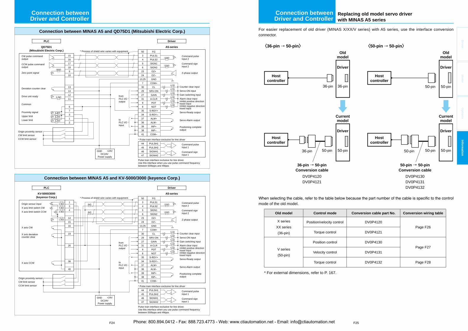
F25
Driver
Mo
tor
Op
tion
sIn
form
ation
F24
DC24VPower supply
Driver
A5-series
PLC
Driver
A5-series
PLC
DC24VPower supply
5034562324
13,257302927319835343736393841
FGPULS1PULS2SIGN1SIGN2OZ+OZGND
COM+CL
SRV-ONGAINA-CLRPOTNOT
S-RDY+S-RDYALM+ALMINP+INP
COM
Connection between MINAS A5 and QD75D1 (Mitsubishi Electric Corp.)
44454647
PULSH1PULSH2SIGNH1SIGNH2
QD75D1(Mitsubishi Electric Corp.)
fromPLC I/O output
toPLC I/O input
15161718910
13141211
67312
5034562324
13,257302927319835343736393841
FGPULS1PULS2SIGN1SIGN2OZ+OZGND
COM+CL
SRV-ONGAINA-CLRPOTNOT
S-RDY+S-RDYALM+ALMINP+INP
COM
Connection between MINAS A5 and KV-5000/3000 (keyence Corp.)
44454647
PULSH1PULSH2SIGNH1SIGNH2
KV-5000/3000(keyence Corp.)
fromPLC I/O output
toPLC I/O input
134
141516
19
26
36
40
Command pulse input 2
Counter clear inputServo-ON input
Servo-Ready output
Servo-Alarm output
Positioning complete output
Alarm clear input
Z-phase output
Command sign input 2
Command pulse input 1
Command sign input 1
Gain switching input
Inhibit negative directiontravel input
Inhibit positive direction travel input
2k
2k
GND +24V
* Process of shield wire varies with equipment.
* Pulse train interface exclusive for line driver
Pulse train interface exclusive for line driver. Use this interface when you use pulse command frequency between 500kpps and 4Mpps
* Process of shield wire varies with equipment.
* Pulse train interface exclusive for line driver
Pulse train interface exclusive for line driver. Use this interface when you use pulse command frequency between 500kpps and 4Mpps
GND +24V
CW limit sensorOrigin proximity sensor
CCW limit sensor
CW limit sensorOrigin proximity sensor
CCW limit sensor
CW pulse command output
CCW pulse command output
Zero point signal
Deviation counter clear
Common
Proximity signalUpper limitLower limit
Drive unit ready
Origin sensor inputX axis limit switch CWX axis limit switch CCW
X axis CW
X sxis deviation counter clear
X axis CCW
220
220
4.7
300
4.7
4.7
4.7
4.7
4.7
220
220
4.7
4.7
4.7
4.7
4.7
4.7
4.7k
4.7k
4.3k
4.7k
4.3k
4.3k
4.3k
1.2k
Connection between Driver and Controller
Replacing old model servo driver with MINAS A5 series
For easier replacement of old driver (MINAS X/XX/V series) with A5 series, use the interface conversion connector.
Driver
36-pin36-pin
Oldmodel
Hostcontroller
Driver
50-pin36-pin 50-pin
Currentmodel
36-pin→ 50-pinConversion cable
DV0P4120DV0P4121
〈36-pin → 50-pin〉 〈50-pin → 50-pin〉
Hostcontroller
Oldmodel
Hostcontroller
Driver
50-pin50-pin 50-pin
50-pin
Currentmodel
Hostcontroller
Driver
50-pin
50-pin→ 50-pinConversion cable
DV0P4130DV0P4131DV0P4132
mode of the old model.
Old model Control mode Conversion cable part No. Conversion wiring table
X seriesXX series(36-pin)
Position/velocity control DV0P4120Page F26
Torque control DV0P4121
V series(50-pin)
Position control DV0P4130Page F27
Velocity control DV0P4131
Torque control DV0P4132 Page F28
* For external dimensions, refer to P. 167.
Connection between Driver and Controller
Phone: 800.894.0412 - Fax: 888.723.4773 - Web: www.ctiautomation.net - Email: [email protected]
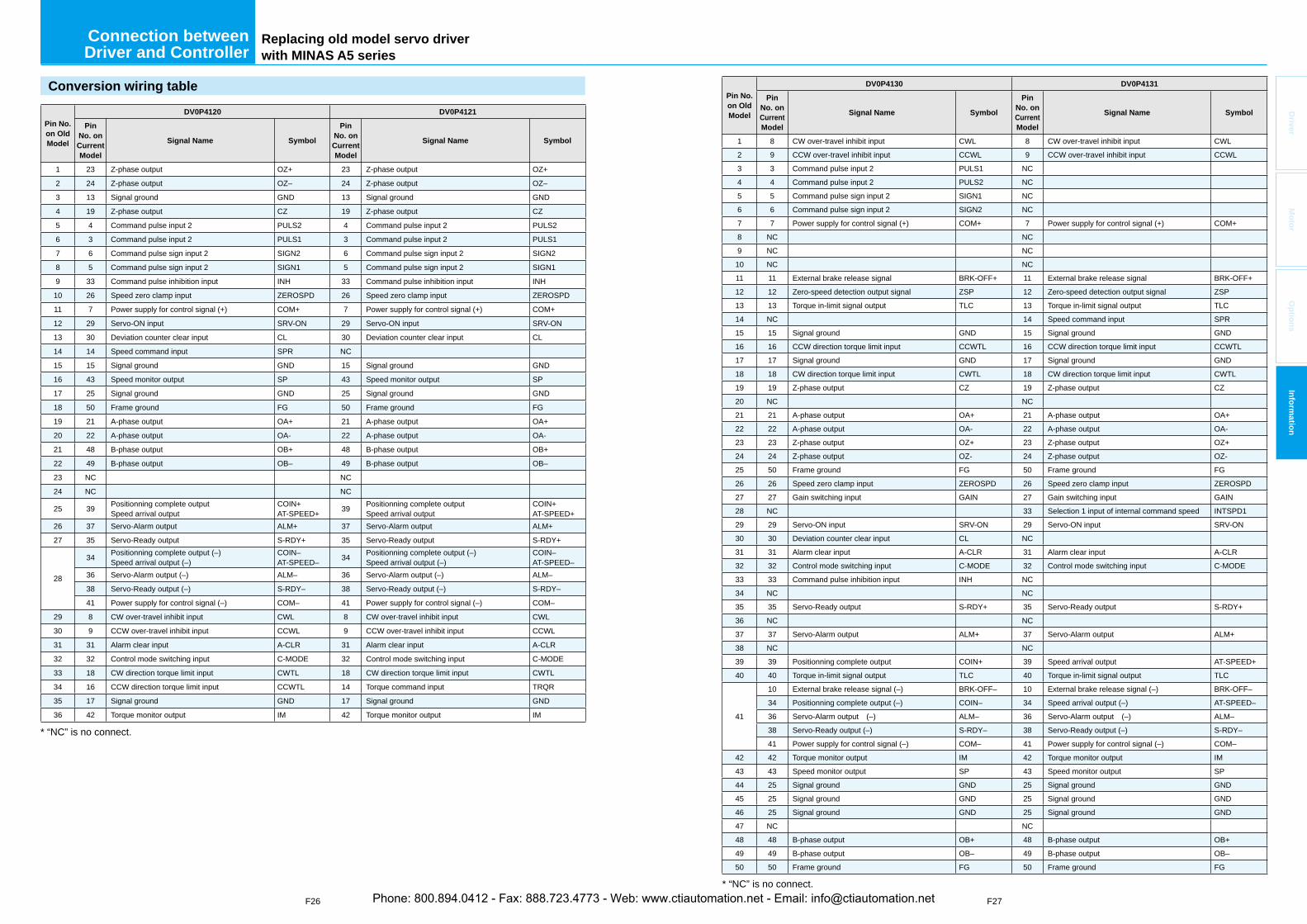
F26 F27
Driver
Mo
tor
Op
tion
sIn
form
ation
Replacing old model servo driver with MINAS A5 series
Conversion wiring table
Pin No. on Old Model
DV0P4120 DV0P4121
PinNo. on CurrentModel
Signal Name Symbol
PinNo. on CurrentModel
Signal Name Symbol
1 23 Z-phase output OZ+ 23 Z-phase output OZ+
2 24 Z-phase output OZ– 24 Z-phase output OZ–
3 13 Signal ground GND 13 Signal ground GND
4 19 Z-phase output CZ 19 Z-phase output CZ
5 4 Command pulse input 2 PULS2 4 Command pulse input 2 PULS2
6 3 Command pulse input 2 PULS1 3 Command pulse input 2 PULS1
7 6 Command pulse sign input 2 SIGN2 6 Command pulse sign input 2 SIGN2
8 5 Command pulse sign input 2 SIGN1 5 Command pulse sign input 2 SIGN1
9 33 Command pulse inhibition input INH 33 Command pulse inhibition input INH
10 26 Speed zero clamp input ZEROSPD 26 Speed zero clamp input ZEROSPD
11 7 Power supply for control signal (+) COM+ 7 Power supply for control signal (+) COM+
12 29 Servo-ON input SRV-ON 29 Servo-ON input SRV-ON
13 30 Deviation counter clear input CL 30 Deviation counter clear input CL
14 14 Speed command input SPR NC
15 15 Signal ground GND 15 Signal ground GND
16 43 Speed monitor output SP 43 Speed monitor output SP
17 25 Signal ground GND 25 Signal ground GND
18 50 Frame ground FG 50 Frame ground FG
19 21 A-phase output OA+ 21 A-phase output OA+
20 22 A-phase output OA- 22 A-phase output OA-
21 48 B-phase output OB+ 48 B-phase output OB+
22 49 B-phase output OB– 49 B-phase output OB–
23 NC NC
24 NC NC
25 39 Positionning complete outputSpeed arrival output
COIN+AT-SPEED+ 39 Positionning complete output
Speed arrival output COIN+AT-SPEED+
26 37 Servo-Alarm output ALM+ 37 Servo-Alarm output ALM+
27 35 Servo-Ready output S-RDY+ 35 Servo-Ready output S-RDY+
28
34 Positionning complete output (–)Speed arrival output (–)
COIN–AT-SPEED– 34 Positionning complete output (–)
Speed arrival output (–)COIN–AT-SPEED–
36 Servo-Alarm output (–) ALM– 36 Servo-Alarm output (–) ALM–
38 Servo-Ready output (–) S-RDY– 38 Servo-Ready output (–) S-RDY–
41 Power supply for control signal (–) COM– 41 Power supply for control signal (–) COM–
29 8 CW over-travel inhibit input CWL 8 CW over-travel inhibit input CWL
30 9 CCW over-travel inhibit input CCWL 9 CCW over-travel inhibit input CCWL
31 31 Alarm clear input A-CLR 31 Alarm clear input A-CLR
32 32 Control mode switching input C-MODE 32 Control mode switching input C-MODE
33 18 CW direction torque limit input CWTL 18 CW direction torque limit input CWTL
34 16 CCW direction torque limit input CCWTL 14 Torque command input TRQR
35 17 Signal ground GND 17 Signal ground GND
36 42 Torque monitor output IM 42 Torque monitor output IM
* “NC” is no connect.
Pin No. on Old Model
DV0P4130 DV0P4131
PinNo. on CurrentModel
Signal Name Symbol
PinNo. on CurrentModel
Signal Name Symbol
1 8 CW over-travel inhibit input CWL 8 CW over-travel inhibit input CWL2 9 CCW over-travel inhibit input CCWL 9 CCW over-travel inhibit input CCWL3 3 Command pulse input 2 PULS1 NC4 4 Command pulse input 2 PULS2 NC5 5 Command pulse sign input 2 SIGN1 NC6 6 Command pulse sign input 2 SIGN2 NC7 7 Power supply for control signal (+) COM+ 7 Power supply for control signal (+) COM+8 NC NC9 NC NC10 NC NC11 11 External brake release signal BRK-OFF+ 11 External brake release signal BRK-OFF+12 12 Zero-speed detection output signal ZSP 12 Zero-speed detection output signal ZSP13 13 Torque in-limit signal output TLC 13 Torque in-limit signal output TLC14 NC 14 Speed command input SPR15 15 Signal ground GND 15 Signal ground GND16 16 CCW direction torque limit input CCWTL 16 CCW direction torque limit input CCWTL17 17 Signal ground GND 17 Signal ground GND18 18 CW direction torque limit input CWTL 18 CW direction torque limit input CWTL19 19 Z-phase output CZ 19 Z-phase output CZ20 NC NC21 21 A-phase output OA+ 21 A-phase output OA+22 22 A-phase output OA- 22 A-phase output OA-23 23 Z-phase output OZ+ 23 Z-phase output OZ+24 24 Z-phase output OZ- 24 Z-phase output OZ-25 50 Frame ground FG 50 Frame ground FG26 26 Speed zero clamp input ZEROSPD 26 Speed zero clamp input ZEROSPD27 27 Gain switching input GAIN 27 Gain switching input GAIN28 NC 33 Selection 1 input of internal command speed INTSPD129 29 Servo-ON input SRV-ON 29 Servo-ON input SRV-ON30 30 Deviation counter clear input CL NC31 31 Alarm clear input A-CLR 31 Alarm clear input A-CLR32 32 Control mode switching input C-MODE 32 Control mode switching input C-MODE33 33 Command pulse inhibition input INH NC34 NC NC35 35 Servo-Ready output S-RDY+ 35 Servo-Ready output S-RDY+36 NC NC37 37 Servo-Alarm output ALM+ 37 Servo-Alarm output ALM+38 NC NC39 39 Positionning complete output COIN+ 39 Speed arrival output AT-SPEED+40 40 Torque in-limit signal output TLC 40 Torque in-limit signal output TLC
41
10 External brake release signal (–) BRK-OFF– 10 External brake release signal (–) BRK-OFF–34 Positionning complete output (–) COIN– 34 Speed arrival output (–) AT-SPEED–36 Servo-Alarm output (–) ALM– 36 Servo-Alarm output (–) ALM–38 Servo-Ready output (–) S-RDY– 38 Servo-Ready output (–) S-RDY–41 Power supply for control signal (–) COM– 41 Power supply for control signal (–) COM–
42 42 Torque monitor output IM 42 Torque monitor output IM43 43 Speed monitor output SP 43 Speed monitor output SP44 25 Signal ground GND 25 Signal ground GND45 25 Signal ground GND 25 Signal ground GND46 25 Signal ground GND 25 Signal ground GND47 NC NC48 48 B-phase output OB+ 48 B-phase output OB+49 49 B-phase output OB– 49 B-phase output OB–50 50 Frame ground FG 50 Frame ground FG
* “NC” is no connect.
Connection between Driver and Controller
Phone: 800.894.0412 - Fax: 888.723.4773 - Web: www.ctiautomation.net - Email: [email protected]
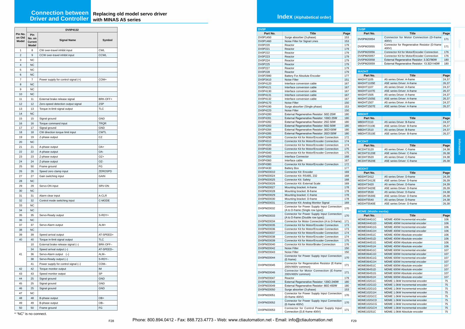
F28 F29
Driver
Mo
tor
Op
tion
sIn
form
ation
Pin No. on Old Model
DV0P4132
PinNo. on CurrentModel
Signal Name Symbol
1 8 CW over-travel inhibit input CWL2 9 CCW over-travel inhibit input CCWL3 NC4 NC5 NC6 NC7 7 Power supply for control signal (+) COM+8 NC9 NC10 NC11 11 External brake release signal BRK-OFF+12 12 Zero-speed detection output signal ZSP13 13 Torque in-limit signal output TLC14 NC15 15 Signal ground GND16 16 Torque command input TRQR17 17 Signal ground GND18 18 CW direction torque limit input CWTL19 19 Z-phase output CZ20 NC21 21 A-phase output OA+22 22 A-phase output OA-23 23 Z-phase output OZ+24 24 Z-phase output OZ-25 50 Frame ground FG26 26 Speed zero clamp input ZEROSPD27 27 Gain switching input GAIN28 NC29 29 Servo-ON input SRV-ON30 NC31 31 Alarm clear input A-CLR32 32 Control mode switching input C-MODE33 NC34 NC35 35 Servo-Ready output S-RDY+36 NC37 37 Servo-Alarm output ALM+38 NC39 39 Speed arrival output AT-SPEED+40 40 Torque in-limit signal output TLC
41
10 External brake release signal (–) BRK-OFF–34 Speed arrival output (–) AT-SPEED–36 Servo-Alarm output (–) ALM–38 Servo-Ready output (–) S-RDY–41 Power supply for control signal (–) COM–
42 42 Torque monitor output IM43 43 Speed monitor output SP44 25 Signal ground GND45 25 Signal ground GND46 25 Signal ground GND47 NC48 48 B-phase output OB+49 49 B-phase output OB–50 50 Frame ground FG
* “NC” is no connect.
Index (Alphabetical order)
DV0PPart No. Title Page
DV0PM20054 Connector for Motor Connection (D-frame 400V) 171
DV0PM20055 Connector for Regenerative Resistor (D-frame 400V) 171
DV0PM20056 Connector Kit for Motor/Encoder Connection 176DV0PM20057 Connector Kit for Motor/Encoder Connection 176DV0PM20058 180DV0PM20059 180
MADHTPart No. Title Page
MADHT1105 A5 series Driver: A-frame 24,37MADHT1105E A5E series Driver: A-frame 26,37MADHT1107 A5 series Driver: A-frame 24,37MADHT1107E A5E series Driver: A-frame 26,37MADHT1505 A5 series Driver: A-frame 24,37MADHT1505E A5E series Driver: A-frame 26,37MADHT1507 A5 series Driver: A-frame 24,37MADHT1507E A5E series Driver: A-frame 26,37
MBDHTPart No. Title Page
MBDHT2110 A5 series Driver: B-frame 24,37MBDHT2110E A5E series Driver: B-frame 26,37MBDHT2510 A5 series Driver: B-frame 24,37MBDHT2510E A5E series Driver: B-frame 26,37
MCDHTPart No. Title Page
MCDHT3120 A5 series Driver: C-frame 24,38MCDHT3120E A5E series Driver: C-frame 26,38MCDHT3520 A5 series Driver: C-frame 24,38MCDHT3520E A5E series Driver: C-frame 26,38
MDDHTPart No. Title Page
MDDHT2412 A5 series Driver: D-frame 24,39MDDHT2412E A5E series Driver: D-frame 26,39MDDHT3420 A5 series Driver: D-frame 24,39MDDHT3420E A5E series Driver: D-frame 26,39MDDHT3530 A5 series Driver: D-frame 24,38MDDHT3530E A5E series Driver: D-frame 26,38MDDHT5540 A5 series Driver: D-frame 24,38MDDHT5540E A5E series Driver: D-frame 26,38
MDME (Middle inertia)Part No. Title Page
MDME044G1C MDME 400W Incremental encoder 106MDME044G1D MDME 400W Incremental encoder 106MDME044G1G MDME 400W Incremental encoder 106MDME044G1H MDME 400W Incremental encoder 106MDME044S1C MDME 400W Absolute encoder 106MDME044S1D MDME 400W Absolute encoder 106MDME044S1G MDME 400W Absolute encoder 106MDME044S1H MDME 400W Absolute encoder 106MDME064G1C MDME 600W Incremental encoder 107MDME064G1D MDME 600W Incremental encoder 107MDME064G1G MDME 600W Incremental encoder 107MDME064G1H MDME 600W Incremental encoder 107MDME064S1C MDME 600W Absolute encoder 107MDME064S1D MDME 600W Absolute encoder 107MDME064S1G MDME 600W Absolute encoder 107MDME064S1H MDME 600W Absolute encoder 107MDME102G1C MDME 1.0kW Incremental encoder 75MDME102G1D MDME 1.0kW Incremental encoder 75MDME102G1G MDME 1.0kW Incremental encoder 75MDME102G1H MDME 1.0kW Incremental encoder 75MDME102GCC MDME 1.0kW Incremental encoder 75MDME102GCD MDME 1.0kW Incremental encoder 75MDME102GCG MDME 1.0kW Incremental encoder 75MDME102GCH MDME 1.0kW Incremental encoder 75MDME102S1C MDME 1.0kW Absolute encoder 75
DV0PPart No. Title Page
DV0P1450 Surge absorber (3-phase) 153DV0P1460 Noise Filter for Signal Lines 153DV0P220 Reactor 179DV0P221 Reactor 179DV0P222 Reactor 179DV0P223 Reactor 179DV0P224 Reactor 179DV0P225 Reactor 179DV0P227 Reactor 179DV0P228 Reactor 179DV0P2990 Battery For Absolute Encoder 177DV0P3410 Noise Filter 151DV0P4120 Interface conversion cable 167DV0P4121 Interface conversion cable 167DV0P4130 Interface conversion cable 167DV0P4131 Interface conversion cable 167DV0P4132 Interface conversion cable 167DV0P4170 Noise Filter 150DV0P4190 Surge absorber (Single phase) 153DV0P4220 Noise Filter 150DV0P4280 180DV0P4281 180DV0P4282 180DV0P4283 180DV0P4284 180DV0P4285 180DV0P4290 Connector Kit for Motor/Encoder Connection 172DV0P4310 Connector Kit for Motor/Encoder Connection 174DV0P4320 Connector Kit for Motor/Encoder Connection 174DV0P4330 Connector Kit for Motor/Encoder Connection 175DV0P4340 Connector Kit for Motor/Encoder Connection 175DV0P4350 Interface Connector 168DV0P4360 Interface cable 167DV0P4380 Connector Kit for Motor/Encoder Connection 172DV0P4430 Battery Box 177DV0PM20010 Connector Kit: Encoder 169DV0PM20024 Connector Kit: RS485, 232 168DV0PM20025 Connector Kit: Safety 168DV0PM20026 Connector Kit: External Scale 169DV0PM20027 Mounting bracket: A-frame 178DV0PM20028 Mounting bracket: B-frame 178DV0PM20029 Mounting bracket: C-frame 178DV0PM20030 Mounting bracket: D-frame 178DV0PM20031 Connector Kit: Analog Monitor Signal 169
DV0PM20032 Connector for Power Supply Input Connection (A to D-frame (Single row type)) 170
DV0PM20033 Connector for Power Supply Input Connection (A to D-frame (Double row type)) 170
DV0PM20034 Connector for Motor Connection (A to D-frame) 171DV0PM20035 Connector Kit for Motor/Encoder Connection 173DV0PM20036 Connector Kit for Motor/Encoder Connection 173DV0PM20037 Connector Kit for Motor/Encoder Connection 174DV0PM20038 Connector Kit for Motor/Encoder Connection 174DV0PM20039 Connector Kit for Motor/Encoder Connection 175DV0PM20040 Connector Kit for Motor/Brake Connection 176DV0PM20042 Noise Filter 150DV0PM20043 Noise Filter 150
DV0PM20044 Connector for Power Supply Input Connection (E-frame) 170
DV0PM20045 Connector for Regenerative Resistor (E-frame 200V/400V common) 171
DV0PM20046 Connector for Motor Connection (E-frame 200V/400V common) 171
DV0PM20047 Reactor 179DV0PM20048 180DV0PM20049 180DV0PM20050 Surge absorber (3-phase) 153
DV0PM20051 Connector for Power Supply Input Connection (D-frame 400V) 170
DV0PM20052 Connector for Power Supply Input Connection (E-frame 400V) 170
DV0PM20053 Connector for Control Power Supply Input Connection (D,E-frame 400V) 171
Replacing old model servo driver with MINAS A5 series
Connection between Driver and Controller
Phone: 800.894.0412 - Fax: 888.723.4773 - Web: www.ctiautomation.net - Email: [email protected]
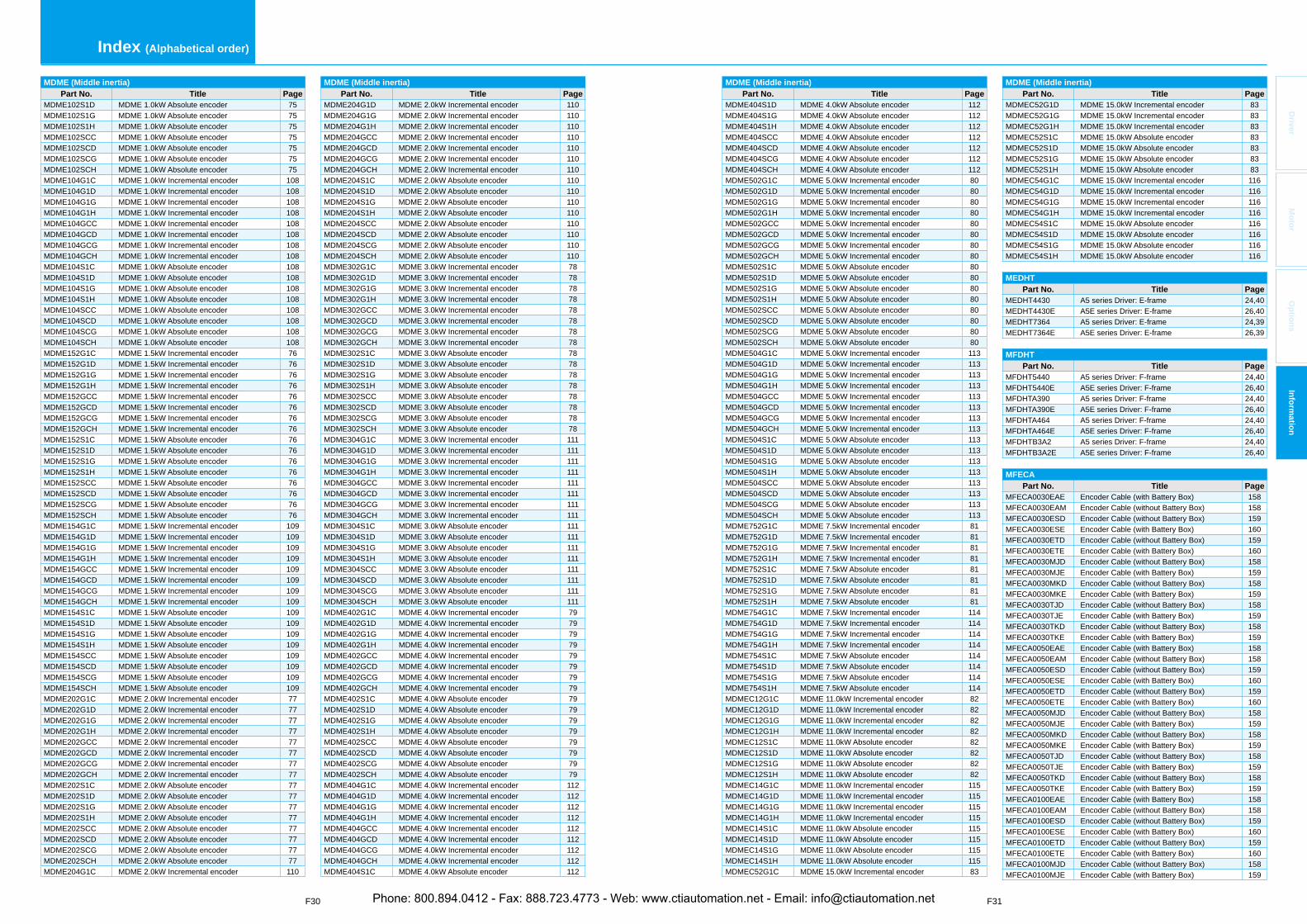
F31
Driver
Mo
tor
Op
tion
sIn
form
ation
F30
MDME (Middle inertia)Part No. Title Page
MDME404S1D MDME 4.0kW Absolute encoder 112MDME404S1G MDME 4.0kW Absolute encoder 112MDME404S1H MDME 4.0kW Absolute encoder 112MDME404SCC MDME 4.0kW Absolute encoder 112MDME404SCD MDME 4.0kW Absolute encoder 112MDME404SCG MDME 4.0kW Absolute encoder 112MDME404SCH MDME 4.0kW Absolute encoder 112MDME502G1C MDME 5.0kW Incremental encoder 80MDME502G1D MDME 5.0kW Incremental encoder 80MDME502G1G MDME 5.0kW Incremental encoder 80MDME502G1H MDME 5.0kW Incremental encoder 80MDME502GCC MDME 5.0kW Incremental encoder 80MDME502GCD MDME 5.0kW Incremental encoder 80MDME502GCG MDME 5.0kW Incremental encoder 80MDME502GCH MDME 5.0kW Incremental encoder 80MDME502S1C MDME 5.0kW Absolute encoder 80MDME502S1D MDME 5.0kW Absolute encoder 80MDME502S1G MDME 5.0kW Absolute encoder 80MDME502S1H MDME 5.0kW Absolute encoder 80MDME502SCC MDME 5.0kW Absolute encoder 80MDME502SCD MDME 5.0kW Absolute encoder 80MDME502SCG MDME 5.0kW Absolute encoder 80MDME502SCH MDME 5.0kW Absolute encoder 80MDME504G1C MDME 5.0kW Incremental encoder 113MDME504G1D MDME 5.0kW Incremental encoder 113MDME504G1G MDME 5.0kW Incremental encoder 113MDME504G1H MDME 5.0kW Incremental encoder 113MDME504GCC MDME 5.0kW Incremental encoder 113MDME504GCD MDME 5.0kW Incremental encoder 113MDME504GCG MDME 5.0kW Incremental encoder 113MDME504GCH MDME 5.0kW Incremental encoder 113MDME504S1C MDME 5.0kW Absolute encoder 113MDME504S1D MDME 5.0kW Absolute encoder 113MDME504S1G MDME 5.0kW Absolute encoder 113MDME504S1H MDME 5.0kW Absolute encoder 113MDME504SCC MDME 5.0kW Absolute encoder 113MDME504SCD MDME 5.0kW Absolute encoder 113MDME504SCG MDME 5.0kW Absolute encoder 113MDME504SCH MDME 5.0kW Absolute encoder 113MDME752G1C MDME 7.5kW Incremental encoder 81MDME752G1D MDME 7.5kW Incremental encoder 81MDME752G1G MDME 7.5kW Incremental encoder 81MDME752G1H MDME 7.5kW Incremental encoder 81MDME752S1C MDME 7.5kW Absolute encoder 81MDME752S1D MDME 7.5kW Absolute encoder 81MDME752S1G MDME 7.5kW Absolute encoder 81MDME752S1H MDME 7.5kW Absolute encoder 81MDME754G1C MDME 7.5kW Incremental encoder 114MDME754G1D MDME 7.5kW Incremental encoder 114MDME754G1G MDME 7.5kW Incremental encoder 114MDME754G1H MDME 7.5kW Incremental encoder 114MDME754S1C MDME 7.5kW Absolute encoder 114MDME754S1D MDME 7.5kW Absolute encoder 114MDME754S1G MDME 7.5kW Absolute encoder 114MDME754S1H MDME 7.5kW Absolute encoder 114MDMEC12G1C MDME 11.0kW Incremental encoder 82MDMEC12G1D MDME 11.0kW Incremental encoder 82MDMEC12G1G MDME 11.0kW Incremental encoder 82MDMEC12G1H MDME 11.0kW Incremental encoder 82MDMEC12S1C MDME 11.0kW Absolute encoder 82MDMEC12S1D MDME 11.0kW Absolute encoder 82MDMEC12S1G MDME 11.0kW Absolute encoder 82MDMEC12S1H MDME 11.0kW Absolute encoder 82MDMEC14G1C MDME 11.0kW Incremental encoder 115MDMEC14G1D MDME 11.0kW Incremental encoder 115MDMEC14G1G MDME 11.0kW Incremental encoder 115MDMEC14G1H MDME 11.0kW Incremental encoder 115MDMEC14S1C MDME 11.0kW Absolute encoder 115MDMEC14S1D MDME 11.0kW Absolute encoder 115MDMEC14S1G MDME 11.0kW Absolute encoder 115MDMEC14S1H MDME 11.0kW Absolute encoder 115MDMEC52G1C MDME 15.0kW Incremental encoder 83
MDME (Middle inertia)Part No. Title Page
MDMEC52G1D MDME 15.0kW Incremental encoder 83MDMEC52G1G MDME 15.0kW Incremental encoder 83MDMEC52G1H MDME 15.0kW Incremental encoder 83MDMEC52S1C MDME 15.0kW Absolute encoder 83MDMEC52S1D MDME 15.0kW Absolute encoder 83MDMEC52S1G MDME 15.0kW Absolute encoder 83MDMEC52S1H MDME 15.0kW Absolute encoder 83MDMEC54G1C MDME 15.0kW Incremental encoder 116MDMEC54G1D MDME 15.0kW Incremental encoder 116MDMEC54G1G MDME 15.0kW Incremental encoder 116MDMEC54G1H MDME 15.0kW Incremental encoder 116MDMEC54S1C MDME 15.0kW Absolute encoder 116MDMEC54S1D MDME 15.0kW Absolute encoder 116MDMEC54S1G MDME 15.0kW Absolute encoder 116MDMEC54S1H MDME 15.0kW Absolute encoder 116
MEDHTPart No. Title Page
MEDHT4430 A5 series Driver: E-frame 24,40MEDHT4430E A5E series Driver: E-frame 26,40MEDHT7364 A5 series Driver: E-frame 24,39MEDHT7364E A5E series Driver: E-frame 26,39
MFDHTPart No. Title Page
MFDHT5440 A5 series Driver: F-frame 24,40MFDHT5440E A5E series Driver: F-frame 26,40MFDHTA390 A5 series Driver: F-frame 24,40MFDHTA390E A5E series Driver: F-frame 26,40MFDHTA464 A5 series Driver: F-frame 24,40MFDHTA464E A5E series Driver: F-frame 26,40MFDHTB3A2 A5 series Driver: F-frame 24,40MFDHTB3A2E A5E series Driver: F-frame 26,40
MFECAPart No. Title Page
MFECA0030EAE Encoder Cable (with Battery Box) 158MFECA0030EAM Encoder Cable (without Battery Box) 158MFECA0030ESD Encoder Cable (without Battery Box) 159MFECA0030ESE Encoder Cable (with Battery Box) 160MFECA0030ETD Encoder Cable (without Battery Box) 159MFECA0030ETE Encoder Cable (with Battery Box) 160MFECA0030MJD Encoder Cable (without Battery Box) 158MFECA0030MJE Encoder Cable (with Battery Box) 159MFECA0030MKD Encoder Cable (without Battery Box) 158MFECA0030MKE Encoder Cable (with Battery Box) 159MFECA0030TJD Encoder Cable (without Battery Box) 158MFECA0030TJE Encoder Cable (with Battery Box) 159MFECA0030TKD Encoder Cable (without Battery Box) 158MFECA0030TKE Encoder Cable (with Battery Box) 159MFECA0050EAE Encoder Cable (with Battery Box) 158MFECA0050EAM Encoder Cable (without Battery Box) 158MFECA0050ESD Encoder Cable (without Battery Box) 159MFECA0050ESE Encoder Cable (with Battery Box) 160MFECA0050ETD Encoder Cable (without Battery Box) 159MFECA0050ETE Encoder Cable (with Battery Box) 160MFECA0050MJD Encoder Cable (without Battery Box) 158MFECA0050MJE Encoder Cable (with Battery Box) 159MFECA0050MKD Encoder Cable (without Battery Box) 158MFECA0050MKE Encoder Cable (with Battery Box) 159MFECA0050TJD Encoder Cable (without Battery Box) 158MFECA0050TJE Encoder Cable (with Battery Box) 159MFECA0050TKD Encoder Cable (without Battery Box) 158MFECA0050TKE Encoder Cable (with Battery Box) 159MFECA0100EAE Encoder Cable (with Battery Box) 158MFECA0100EAM Encoder Cable (without Battery Box) 158MFECA0100ESD Encoder Cable (without Battery Box) 159MFECA0100ESE Encoder Cable (with Battery Box) 160MFECA0100ETD Encoder Cable (without Battery Box) 159MFECA0100ETE Encoder Cable (with Battery Box) 160MFECA0100MJD Encoder Cable (without Battery Box) 158MFECA0100MJE Encoder Cable (with Battery Box) 159
MDME (Middle inertia)Part No. Title Page
MDME102S1D MDME 1.0kW Absolute encoder 75MDME102S1G MDME 1.0kW Absolute encoder 75MDME102S1H MDME 1.0kW Absolute encoder 75MDME102SCC MDME 1.0kW Absolute encoder 75MDME102SCD MDME 1.0kW Absolute encoder 75MDME102SCG MDME 1.0kW Absolute encoder 75MDME102SCH MDME 1.0kW Absolute encoder 75MDME104G1C MDME 1.0kW Incremental encoder 108MDME104G1D MDME 1.0kW Incremental encoder 108MDME104G1G MDME 1.0kW Incremental encoder 108MDME104G1H MDME 1.0kW Incremental encoder 108MDME104GCC MDME 1.0kW Incremental encoder 108MDME104GCD MDME 1.0kW Incremental encoder 108MDME104GCG MDME 1.0kW Incremental encoder 108MDME104GCH MDME 1.0kW Incremental encoder 108MDME104S1C MDME 1.0kW Absolute encoder 108MDME104S1D MDME 1.0kW Absolute encoder 108MDME104S1G MDME 1.0kW Absolute encoder 108MDME104S1H MDME 1.0kW Absolute encoder 108MDME104SCC MDME 1.0kW Absolute encoder 108MDME104SCD MDME 1.0kW Absolute encoder 108MDME104SCG MDME 1.0kW Absolute encoder 108MDME104SCH MDME 1.0kW Absolute encoder 108MDME152G1C MDME 1.5kW Incremental encoder 76MDME152G1D MDME 1.5kW Incremental encoder 76MDME152G1G MDME 1.5kW Incremental encoder 76MDME152G1H MDME 1.5kW Incremental encoder 76MDME152GCC MDME 1.5kW Incremental encoder 76MDME152GCD MDME 1.5kW Incremental encoder 76MDME152GCG MDME 1.5kW Incremental encoder 76MDME152GCH MDME 1.5kW Incremental encoder 76MDME152S1C MDME 1.5kW Absolute encoder 76MDME152S1D MDME 1.5kW Absolute encoder 76MDME152S1G MDME 1.5kW Absolute encoder 76MDME152S1H MDME 1.5kW Absolute encoder 76MDME152SCC MDME 1.5kW Absolute encoder 76MDME152SCD MDME 1.5kW Absolute encoder 76MDME152SCG MDME 1.5kW Absolute encoder 76MDME152SCH MDME 1.5kW Absolute encoder 76MDME154G1C MDME 1.5kW Incremental encoder 109MDME154G1D MDME 1.5kW Incremental encoder 109MDME154G1G MDME 1.5kW Incremental encoder 109MDME154G1H MDME 1.5kW Incremental encoder 109MDME154GCC MDME 1.5kW Incremental encoder 109MDME154GCD MDME 1.5kW Incremental encoder 109MDME154GCG MDME 1.5kW Incremental encoder 109MDME154GCH MDME 1.5kW Incremental encoder 109MDME154S1C MDME 1.5kW Absolute encoder 109MDME154S1D MDME 1.5kW Absolute encoder 109MDME154S1G MDME 1.5kW Absolute encoder 109MDME154S1H MDME 1.5kW Absolute encoder 109MDME154SCC MDME 1.5kW Absolute encoder 109MDME154SCD MDME 1.5kW Absolute encoder 109MDME154SCG MDME 1.5kW Absolute encoder 109MDME154SCH MDME 1.5kW Absolute encoder 109MDME202G1C MDME 2.0kW Incremental encoder 77MDME202G1D MDME 2.0kW Incremental encoder 77MDME202G1G MDME 2.0kW Incremental encoder 77MDME202G1H MDME 2.0kW Incremental encoder 77MDME202GCC MDME 2.0kW Incremental encoder 77MDME202GCD MDME 2.0kW Incremental encoder 77MDME202GCG MDME 2.0kW Incremental encoder 77MDME202GCH MDME 2.0kW Incremental encoder 77MDME202S1C MDME 2.0kW Absolute encoder 77MDME202S1D MDME 2.0kW Absolute encoder 77MDME202S1G MDME 2.0kW Absolute encoder 77MDME202S1H MDME 2.0kW Absolute encoder 77MDME202SCC MDME 2.0kW Absolute encoder 77MDME202SCD MDME 2.0kW Absolute encoder 77MDME202SCG MDME 2.0kW Absolute encoder 77MDME202SCH MDME 2.0kW Absolute encoder 77MDME204G1C MDME 2.0kW Incremental encoder 110
MDME (Middle inertia)Part No. Title Page
MDME204G1D MDME 2.0kW Incremental encoder 110MDME204G1G MDME 2.0kW Incremental encoder 110MDME204G1H MDME 2.0kW Incremental encoder 110MDME204GCC MDME 2.0kW Incremental encoder 110MDME204GCD MDME 2.0kW Incremental encoder 110MDME204GCG MDME 2.0kW Incremental encoder 110MDME204GCH MDME 2.0kW Incremental encoder 110MDME204S1C MDME 2.0kW Absolute encoder 110MDME204S1D MDME 2.0kW Absolute encoder 110MDME204S1G MDME 2.0kW Absolute encoder 110MDME204S1H MDME 2.0kW Absolute encoder 110MDME204SCC MDME 2.0kW Absolute encoder 110MDME204SCD MDME 2.0kW Absolute encoder 110MDME204SCG MDME 2.0kW Absolute encoder 110MDME204SCH MDME 2.0kW Absolute encoder 110MDME302G1C MDME 3.0kW Incremental encoder 78MDME302G1D MDME 3.0kW Incremental encoder 78MDME302G1G MDME 3.0kW Incremental encoder 78MDME302G1H MDME 3.0kW Incremental encoder 78MDME302GCC MDME 3.0kW Incremental encoder 78MDME302GCD MDME 3.0kW Incremental encoder 78MDME302GCG MDME 3.0kW Incremental encoder 78MDME302GCH MDME 3.0kW Incremental encoder 78MDME302S1C MDME 3.0kW Absolute encoder 78MDME302S1D MDME 3.0kW Absolute encoder 78MDME302S1G MDME 3.0kW Absolute encoder 78MDME302S1H MDME 3.0kW Absolute encoder 78MDME302SCC MDME 3.0kW Absolute encoder 78MDME302SCD MDME 3.0kW Absolute encoder 78MDME302SCG MDME 3.0kW Absolute encoder 78MDME302SCH MDME 3.0kW Absolute encoder 78MDME304G1C MDME 3.0kW Incremental encoder 111MDME304G1D MDME 3.0kW Incremental encoder 111MDME304G1G MDME 3.0kW Incremental encoder 111MDME304G1H MDME 3.0kW Incremental encoder 111MDME304GCC MDME 3.0kW Incremental encoder 111MDME304GCD MDME 3.0kW Incremental encoder 111MDME304GCG MDME 3.0kW Incremental encoder 111MDME304GCH MDME 3.0kW Incremental encoder 111MDME304S1C MDME 3.0kW Absolute encoder 111MDME304S1D MDME 3.0kW Absolute encoder 111MDME304S1G MDME 3.0kW Absolute encoder 111MDME304S1H MDME 3.0kW Absolute encoder 111MDME304SCC MDME 3.0kW Absolute encoder 111MDME304SCD MDME 3.0kW Absolute encoder 111MDME304SCG MDME 3.0kW Absolute encoder 111MDME304SCH MDME 3.0kW Absolute encoder 111MDME402G1C MDME 4.0kW Incremental encoder 79MDME402G1D MDME 4.0kW Incremental encoder 79MDME402G1G MDME 4.0kW Incremental encoder 79MDME402G1H MDME 4.0kW Incremental encoder 79MDME402GCC MDME 4.0kW Incremental encoder 79MDME402GCD MDME 4.0kW Incremental encoder 79MDME402GCG MDME 4.0kW Incremental encoder 79MDME402GCH MDME 4.0kW Incremental encoder 79MDME402S1C MDME 4.0kW Absolute encoder 79MDME402S1D MDME 4.0kW Absolute encoder 79MDME402S1G MDME 4.0kW Absolute encoder 79MDME402S1H MDME 4.0kW Absolute encoder 79MDME402SCC MDME 4.0kW Absolute encoder 79MDME402SCD MDME 4.0kW Absolute encoder 79MDME402SCG MDME 4.0kW Absolute encoder 79MDME402SCH MDME 4.0kW Absolute encoder 79MDME404G1C MDME 4.0kW Incremental encoder 112MDME404G1D MDME 4.0kW Incremental encoder 112MDME404G1G MDME 4.0kW Incremental encoder 112MDME404G1H MDME 4.0kW Incremental encoder 112MDME404GCC MDME 4.0kW Incremental encoder 112MDME404GCD MDME 4.0kW Incremental encoder 112MDME404GCG MDME 4.0kW Incremental encoder 112MDME404GCH MDME 4.0kW Incremental encoder 112MDME404S1C MDME 4.0kW Absolute encoder 112
Index (Alphabetical order)
Phone: 800.894.0412 - Fax: 888.723.4773 - Web: www.ctiautomation.net - Email: [email protected]
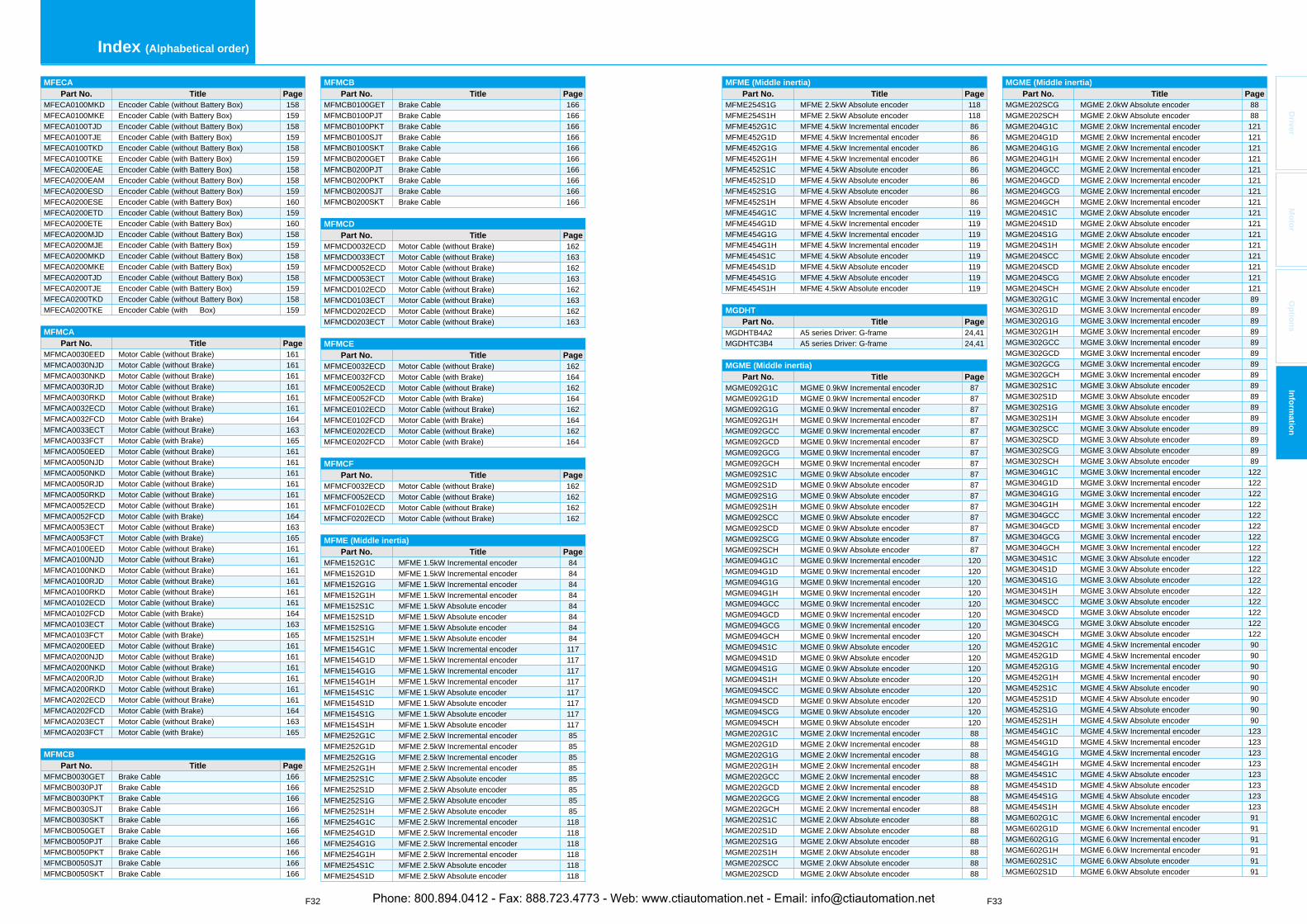
F32 F33
Index (Alphabetical order)
Driver
Mo
tor
Op
tion
sIn
form
ation
MFECAPart No. Title Page
MFECA0100MKD Encoder Cable (without Battery Box) 158MFECA0100MKE Encoder Cable (with Battery Box) 159MFECA0100TJD Encoder Cable (without Battery Box) 158MFECA0100TJE Encoder Cable (with Battery Box) 159MFECA0100TKD Encoder Cable (without Battery Box) 158MFECA0100TKE Encoder Cable (with Battery Box) 159MFECA0200EAE Encoder Cable (with Battery Box) 158MFECA0200EAM Encoder Cable (without Battery Box) 158MFECA0200ESD Encoder Cable (without Battery Box) 159MFECA0200ESE Encoder Cable (with Battery Box) 160MFECA0200ETD Encoder Cable (without Battery Box) 159MFECA0200ETE Encoder Cable (with Battery Box) 160MFECA0200MJD Encoder Cable (without Battery Box) 158MFECA0200MJE Encoder Cable (with Battery Box) 159MFECA0200MKD Encoder Cable (without Battery Box) 158MFECA0200MKE Encoder Cable (with Battery Box) 159MFECA0200TJD Encoder Cable (without Battery Box) 158MFECA0200TJE Encoder Cable (with Battery Box) 159MFECA0200TKD Encoder Cable (without Battery Box) 158MFECA0200TKE Encoder Cable (with Box) 159
MFMCAPart No. Title Page
MFMCA0030EED Motor Cable (without Brake) 161MFMCA0030NJD Motor Cable (without Brake) 161MFMCA0030NKD Motor Cable (without Brake) 161MFMCA0030RJD Motor Cable (without Brake) 161MFMCA0030RKD Motor Cable (without Brake) 161MFMCA0032ECD Motor Cable (without Brake) 161MFMCA0032FCD Motor Cable (with Brake) 164MFMCA0033ECT Motor Cable (without Brake) 163MFMCA0033FCT Motor Cable (with Brake) 165MFMCA0050EED Motor Cable (without Brake) 161MFMCA0050NJD Motor Cable (without Brake) 161MFMCA0050NKD Motor Cable (without Brake) 161MFMCA0050RJD Motor Cable (without Brake) 161MFMCA0050RKD Motor Cable (without Brake) 161MFMCA0052ECD Motor Cable (without Brake) 161MFMCA0052FCD Motor Cable (with Brake) 164MFMCA0053ECT Motor Cable (without Brake) 163MFMCA0053FCT Motor Cable (with Brake) 165MFMCA0100EED Motor Cable (without Brake) 161MFMCA0100NJD Motor Cable (without Brake) 161MFMCA0100NKD Motor Cable (without Brake) 161MFMCA0100RJD Motor Cable (without Brake) 161MFMCA0100RKD Motor Cable (without Brake) 161MFMCA0102ECD Motor Cable (without Brake) 161MFMCA0102FCD Motor Cable (with Brake) 164MFMCA0103ECT Motor Cable (without Brake) 163MFMCA0103FCT Motor Cable (with Brake) 165MFMCA0200EED Motor Cable (without Brake) 161MFMCA0200NJD Motor Cable (without Brake) 161MFMCA0200NKD Motor Cable (without Brake) 161MFMCA0200RJD Motor Cable (without Brake) 161MFMCA0200RKD Motor Cable (without Brake) 161MFMCA0202ECD Motor Cable (without Brake) 161MFMCA0202FCD Motor Cable (with Brake) 164MFMCA0203ECT Motor Cable (without Brake) 163MFMCA0203FCT Motor Cable (with Brake) 165
MFMCBPart No. Title Page
MFMCB0030GET Brake Cable 166MFMCB0030PJT Brake Cable 166MFMCB0030PKT Brake Cable 166MFMCB0030SJT Brake Cable 166MFMCB0030SKT Brake Cable 166MFMCB0050GET Brake Cable 166MFMCB0050PJT Brake Cable 166MFMCB0050PKT Brake Cable 166MFMCB0050SJT Brake Cable 166MFMCB0050SKT Brake Cable 166
MFMCBPart No. Title Page
MFMCB0100GET Brake Cable 166MFMCB0100PJT Brake Cable 166MFMCB0100PKT Brake Cable 166MFMCB0100SJT Brake Cable 166MFMCB0100SKT Brake Cable 166MFMCB0200GET Brake Cable 166MFMCB0200PJT Brake Cable 166MFMCB0200PKT Brake Cable 166MFMCB0200SJT Brake Cable 166MFMCB0200SKT Brake Cable 166
MFMCDPart No. Title Page
MFMCD0032ECD Motor Cable (without Brake) 162MFMCD0033ECT Motor Cable (without Brake) 163MFMCD0052ECD Motor Cable (without Brake) 162MFMCD0053ECT Motor Cable (without Brake) 163MFMCD0102ECD Motor Cable (without Brake) 162MFMCD0103ECT Motor Cable (without Brake) 163MFMCD0202ECD Motor Cable (without Brake) 162MFMCD0203ECT Motor Cable (without Brake) 163
MFMCEPart No. Title Page
MFMCE0032ECD Motor Cable (without Brake) 162MFMCE0032FCD Motor Cable (with Brake) 164MFMCE0052ECD Motor Cable (without Brake) 162MFMCE0052FCD Motor Cable (with Brake) 164MFMCE0102ECD Motor Cable (without Brake) 162MFMCE0102FCD Motor Cable (with Brake) 164MFMCE0202ECD Motor Cable (without Brake) 162MFMCE0202FCD Motor Cable (with Brake) 164
MFMCFPart No. Title Page
MFMCF0032ECD Motor Cable (without Brake) 162MFMCF0052ECD Motor Cable (without Brake) 162MFMCF0102ECD Motor Cable (without Brake) 162MFMCF0202ECD Motor Cable (without Brake) 162
MFME (Middle inertia)Part No. Title Page
MFME152G1C MFME 1.5kW Incremental encoder 84MFME152G1D MFME 1.5kW Incremental encoder 84MFME152G1G MFME 1.5kW Incremental encoder 84MFME152G1H MFME 1.5kW Incremental encoder 84MFME152S1C MFME 1.5kW Absolute encoder 84MFME152S1D MFME 1.5kW Absolute encoder 84MFME152S1G MFME 1.5kW Absolute encoder 84MFME152S1H MFME 1.5kW Absolute encoder 84MFME154G1C MFME 1.5kW Incremental encoder 117MFME154G1D MFME 1.5kW Incremental encoder 117MFME154G1G MFME 1.5kW Incremental encoder 117MFME154G1H MFME 1.5kW Incremental encoder 117MFME154S1C MFME 1.5kW Absolute encoder 117MFME154S1D MFME 1.5kW Absolute encoder 117MFME154S1G MFME 1.5kW Absolute encoder 117MFME154S1H MFME 1.5kW Absolute encoder 117MFME252G1C MFME 2.5kW Incremental encoder 85MFME252G1D MFME 2.5kW Incremental encoder 85MFME252G1G MFME 2.5kW Incremental encoder 85MFME252G1H MFME 2.5kW Incremental encoder 85MFME252S1C MFME 2.5kW Absolute encoder 85MFME252S1D MFME 2.5kW Absolute encoder 85MFME252S1G MFME 2.5kW Absolute encoder 85MFME252S1H MFME 2.5kW Absolute encoder 85MFME254G1C MFME 2.5kW Incremental encoder 118MFME254G1D MFME 2.5kW Incremental encoder 118MFME254G1G MFME 2.5kW Incremental encoder 118MFME254G1H MFME 2.5kW Incremental encoder 118MFME254S1C MFME 2.5kW Absolute encoder 118MFME254S1D MFME 2.5kW Absolute encoder 118
MFME (Middle inertia)Part No. Title Page
MFME254S1G MFME 2.5kW Absolute encoder 118MFME254S1H MFME 2.5kW Absolute encoder 118MFME452G1C MFME 4.5kW Incremental encoder 86MFME452G1D MFME 4.5kW Incremental encoder 86MFME452G1G MFME 4.5kW Incremental encoder 86MFME452G1H MFME 4.5kW Incremental encoder 86MFME452S1C MFME 4.5kW Absolute encoder 86MFME452S1D MFME 4.5kW Absolute encoder 86MFME452S1G MFME 4.5kW Absolute encoder 86MFME452S1H MFME 4.5kW Absolute encoder 86MFME454G1C MFME 4.5kW Incremental encoder 119MFME454G1D MFME 4.5kW Incremental encoder 119MFME454G1G MFME 4.5kW Incremental encoder 119MFME454G1H MFME 4.5kW Incremental encoder 119MFME454S1C MFME 4.5kW Absolute encoder 119MFME454S1D MFME 4.5kW Absolute encoder 119MFME454S1G MFME 4.5kW Absolute encoder 119MFME454S1H MFME 4.5kW Absolute encoder 119
MGDHTPart No. Title Page
MGDHTB4A2 A5 series Driver: G-frame 24,41MGDHTC3B4 A5 series Driver: G-frame 24,41
MGME (Middle inertia)Part No. Title Page
MGME092G1C MGME 0.9kW Incremental encoder 87MGME092G1D MGME 0.9kW Incremental encoder 87MGME092G1G MGME 0.9kW Incremental encoder 87MGME092G1H MGME 0.9kW Incremental encoder 87MGME092GCC MGME 0.9kW Incremental encoder 87MGME092GCD MGME 0.9kW Incremental encoder 87MGME092GCG MGME 0.9kW Incremental encoder 87MGME092GCH MGME 0.9kW Incremental encoder 87MGME092S1C MGME 0.9kW Absolute encoder 87MGME092S1D MGME 0.9kW Absolute encoder 87MGME092S1G MGME 0.9kW Absolute encoder 87MGME092S1H MGME 0.9kW Absolute encoder 87MGME092SCC MGME 0.9kW Absolute encoder 87MGME092SCD MGME 0.9kW Absolute encoder 87MGME092SCG MGME 0.9kW Absolute encoder 87MGME092SCH MGME 0.9kW Absolute encoder 87MGME094G1C MGME 0.9kW Incremental encoder 120MGME094G1D MGME 0.9kW Incremental encoder 120MGME094G1G MGME 0.9kW Incremental encoder 120MGME094G1H MGME 0.9kW Incremental encoder 120MGME094GCC MGME 0.9kW Incremental encoder 120MGME094GCD MGME 0.9kW Incremental encoder 120MGME094GCG MGME 0.9kW Incremental encoder 120MGME094GCH MGME 0.9kW Incremental encoder 120MGME094S1C MGME 0.9kW Absolute encoder 120MGME094S1D MGME 0.9kW Absolute encoder 120MGME094S1G MGME 0.9kW Absolute encoder 120MGME094S1H MGME 0.9kW Absolute encoder 120MGME094SCC MGME 0.9kW Absolute encoder 120MGME094SCD MGME 0.9kW Absolute encoder 120MGME094SCG MGME 0.9kW Absolute encoder 120MGME094SCH MGME 0.9kW Absolute encoder 120MGME202G1C MGME 2.0kW Incremental encoder 88MGME202G1D MGME 2.0kW Incremental encoder 88MGME202G1G MGME 2.0kW Incremental encoder 88MGME202G1H MGME 2.0kW Incremental encoder 88MGME202GCC MGME 2.0kW Incremental encoder 88MGME202GCD MGME 2.0kW Incremental encoder 88MGME202GCG MGME 2.0kW Incremental encoder 88MGME202GCH MGME 2.0kW Incremental encoder 88MGME202S1C MGME 2.0kW Absolute encoder 88MGME202S1D MGME 2.0kW Absolute encoder 88MGME202S1G MGME 2.0kW Absolute encoder 88MGME202S1H MGME 2.0kW Absolute encoder 88MGME202SCC MGME 2.0kW Absolute encoder 88MGME202SCD MGME 2.0kW Absolute encoder 88
MGME (Middle inertia)Part No. Title Page
MGME202SCG MGME 2.0kW Absolute encoder 88MGME202SCH MGME 2.0kW Absolute encoder 88MGME204G1C MGME 2.0kW Incremental encoder 121MGME204G1D MGME 2.0kW Incremental encoder 121MGME204G1G MGME 2.0kW Incremental encoder 121MGME204G1H MGME 2.0kW Incremental encoder 121MGME204GCC MGME 2.0kW Incremental encoder 121MGME204GCD MGME 2.0kW Incremental encoder 121MGME204GCG MGME 2.0kW Incremental encoder 121MGME204GCH MGME 2.0kW Incremental encoder 121MGME204S1C MGME 2.0kW Absolute encoder 121MGME204S1D MGME 2.0kW Absolute encoder 121MGME204S1G MGME 2.0kW Absolute encoder 121MGME204S1H MGME 2.0kW Absolute encoder 121MGME204SCC MGME 2.0kW Absolute encoder 121MGME204SCD MGME 2.0kW Absolute encoder 121MGME204SCG MGME 2.0kW Absolute encoder 121MGME204SCH MGME 2.0kW Absolute encoder 121MGME302G1C MGME 3.0kW Incremental encoder 89MGME302G1D MGME 3.0kW Incremental encoder 89MGME302G1G MGME 3.0kW Incremental encoder 89MGME302G1H MGME 3.0kW Incremental encoder 89MGME302GCC MGME 3.0kW Incremental encoder 89MGME302GCD MGME 3.0kW Incremental encoder 89MGME302GCG MGME 3.0kW Incremental encoder 89MGME302GCH MGME 3.0kW Incremental encoder 89MGME302S1C MGME 3.0kW Absolute encoder 89MGME302S1D MGME 3.0kW Absolute encoder 89MGME302S1G MGME 3.0kW Absolute encoder 89MGME302S1H MGME 3.0kW Absolute encoder 89MGME302SCC MGME 3.0kW Absolute encoder 89MGME302SCD MGME 3.0kW Absolute encoder 89MGME302SCG MGME 3.0kW Absolute encoder 89MGME302SCH MGME 3.0kW Absolute encoder 89MGME304G1C MGME 3.0kW Incremental encoder 122MGME304G1D MGME 3.0kW Incremental encoder 122MGME304G1G MGME 3.0kW Incremental encoder 122MGME304G1H MGME 3.0kW Incremental encoder 122MGME304GCC MGME 3.0kW Incremental encoder 122MGME304GCD MGME 3.0kW Incremental encoder 122MGME304GCG MGME 3.0kW Incremental encoder 122MGME304GCH MGME 3.0kW Incremental encoder 122MGME304S1C MGME 3.0kW Absolute encoder 122MGME304S1D MGME 3.0kW Absolute encoder 122MGME304S1G MGME 3.0kW Absolute encoder 122MGME304S1H MGME 3.0kW Absolute encoder 122MGME304SCC MGME 3.0kW Absolute encoder 122MGME304SCD MGME 3.0kW Absolute encoder 122MGME304SCG MGME 3.0kW Absolute encoder 122MGME304SCH MGME 3.0kW Absolute encoder 122MGME452G1C MGME 4.5kW Incremental encoder 90MGME452G1D MGME 4.5kW Incremental encoder 90MGME452G1G MGME 4.5kW Incremental encoder 90MGME452G1H MGME 4.5kW Incremental encoder 90MGME452S1C MGME 4.5kW Absolute encoder 90MGME452S1D MGME 4.5kW Absolute encoder 90MGME452S1G MGME 4.5kW Absolute encoder 90MGME452S1H MGME 4.5kW Absolute encoder 90MGME454G1C MGME 4.5kW Incremental encoder 123MGME454G1D MGME 4.5kW Incremental encoder 123MGME454G1G MGME 4.5kW Incremental encoder 123MGME454G1H MGME 4.5kW Incremental encoder 123MGME454S1C MGME 4.5kW Absolute encoder 123MGME454S1D MGME 4.5kW Absolute encoder 123MGME454S1G MGME 4.5kW Absolute encoder 123MGME454S1H MGME 4.5kW Absolute encoder 123MGME602G1C MGME 6.0kW Incremental encoder 91MGME602G1D MGME 6.0kW Incremental encoder 91MGME602G1G MGME 6.0kW Incremental encoder 91MGME602G1H MGME 6.0kW Incremental encoder 91MGME602S1C MGME 6.0kW Absolute encoder 91MGME602S1D MGME 6.0kW Absolute encoder 91
Phone: 800.894.0412 - Fax: 888.723.4773 - Web: www.ctiautomation.net - Email: [email protected]
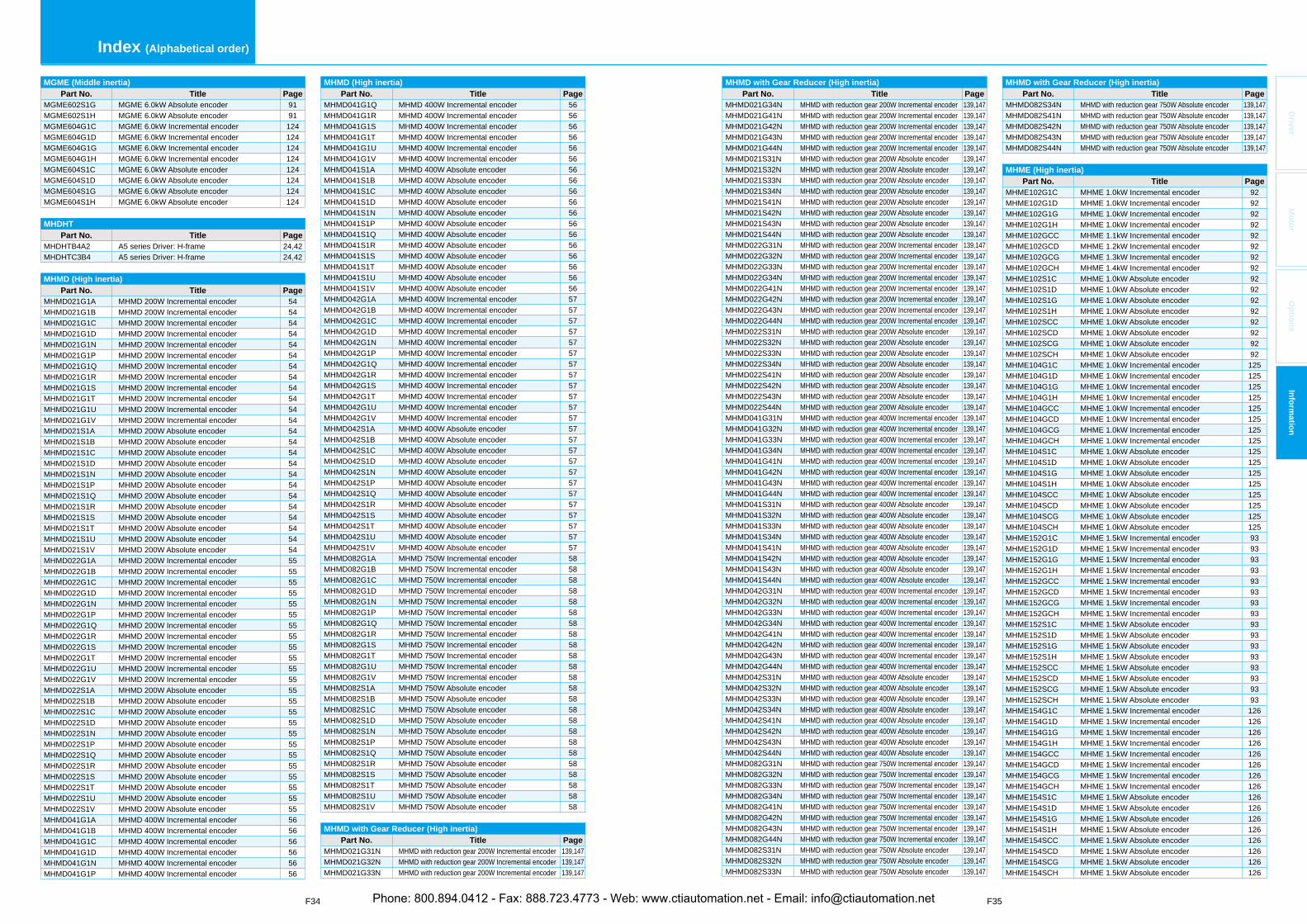
F34 F35
Index (Alphabetical order)
Driver
Mo
tor
Op
tion
sIn
form
ation
MGME (Middle inertia)Part No. Title Page
MGME602S1G MGME 6.0kW Absolute encoder 91MGME602S1H MGME 6.0kW Absolute encoder 91MGME604G1C MGME 6.0kW Incremental encoder 124MGME604G1D MGME 6.0kW Incremental encoder 124MGME604G1G MGME 6.0kW Incremental encoder 124MGME604G1H MGME 6.0kW Incremental encoder 124MGME604S1C MGME 6.0kW Absolute encoder 124MGME604S1D MGME 6.0kW Absolute encoder 124MGME604S1G MGME 6.0kW Absolute encoder 124MGME604S1H MGME 6.0kW Absolute encoder 124
MHDHTPart No. Title Page
MHDHTB4A2 A5 series Driver: H-frame 24,42MHDHTC3B4 A5 series Driver: H-frame 24,42
MHMD (High inertia)Part No. Title Page
MHMD021G1A MHMD 200W Incremental encoder 54MHMD021G1B MHMD 200W Incremental encoder 54MHMD021G1C MHMD 200W Incremental encoder 54MHMD021G1D MHMD 200W Incremental encoder 54MHMD021G1N MHMD 200W Incremental encoder 54MHMD021G1P MHMD 200W Incremental encoder 54MHMD021G1Q MHMD 200W Incremental encoder 54MHMD021G1R MHMD 200W Incremental encoder 54MHMD021G1S MHMD 200W Incremental encoder 54MHMD021G1T MHMD 200W Incremental encoder 54MHMD021G1U MHMD 200W Incremental encoder 54MHMD021G1V MHMD 200W Incremental encoder 54MHMD021S1A MHMD 200W Absolute encoder 54MHMD021S1B MHMD 200W Absolute encoder 54MHMD021S1C MHMD 200W Absolute encoder 54MHMD021S1D MHMD 200W Absolute encoder 54MHMD021S1N MHMD 200W Absolute encoder 54MHMD021S1P MHMD 200W Absolute encoder 54MHMD021S1Q MHMD 200W Absolute encoder 54MHMD021S1R MHMD 200W Absolute encoder 54MHMD021S1S MHMD 200W Absolute encoder 54MHMD021S1T MHMD 200W Absolute encoder 54MHMD021S1U MHMD 200W Absolute encoder 54MHMD021S1V MHMD 200W Absolute encoder 54MHMD022G1A MHMD 200W Incremental encoder 55MHMD022G1B MHMD 200W Incremental encoder 55MHMD022G1C MHMD 200W Incremental encoder 55MHMD022G1D MHMD 200W Incremental encoder 55MHMD022G1N MHMD 200W Incremental encoder 55MHMD022G1P MHMD 200W Incremental encoder 55MHMD022G1Q MHMD 200W Incremental encoder 55MHMD022G1R MHMD 200W Incremental encoder 55MHMD022G1S MHMD 200W Incremental encoder 55MHMD022G1T MHMD 200W Incremental encoder 55MHMD022G1U MHMD 200W Incremental encoder 55MHMD022G1V MHMD 200W Incremental encoder 55MHMD022S1A MHMD 200W Absolute encoder 55MHMD022S1B MHMD 200W Absolute encoder 55MHMD022S1C MHMD 200W Absolute encoder 55MHMD022S1D MHMD 200W Absolute encoder 55MHMD022S1N MHMD 200W Absolute encoder 55MHMD022S1P MHMD 200W Absolute encoder 55MHMD022S1Q MHMD 200W Absolute encoder 55MHMD022S1R MHMD 200W Absolute encoder 55MHMD022S1S MHMD 200W Absolute encoder 55MHMD022S1T MHMD 200W Absolute encoder 55MHMD022S1U MHMD 200W Absolute encoder 55MHMD022S1V MHMD 200W Absolute encoder 55MHMD041G1A MHMD 400W Incremental encoder 56MHMD041G1B MHMD 400W Incremental encoder 56MHMD041G1C MHMD 400W Incremental encoder 56MHMD041G1D MHMD 400W Incremental encoder 56MHMD041G1N MHMD 400W Incremental encoder 56MHMD041G1P MHMD 400W Incremental encoder 56
MHMD (High inertia)Part No. Title Page
MHMD041G1Q MHMD 400W Incremental encoder 56MHMD041G1R MHMD 400W Incremental encoder 56MHMD041G1S MHMD 400W Incremental encoder 56MHMD041G1T MHMD 400W Incremental encoder 56MHMD041G1U MHMD 400W Incremental encoder 56MHMD041G1V MHMD 400W Incremental encoder 56MHMD041S1A MHMD 400W Absolute encoder 56MHMD041S1B MHMD 400W Absolute encoder 56MHMD041S1C MHMD 400W Absolute encoder 56MHMD041S1D MHMD 400W Absolute encoder 56MHMD041S1N MHMD 400W Absolute encoder 56MHMD041S1P MHMD 400W Absolute encoder 56MHMD041S1Q MHMD 400W Absolute encoder 56MHMD041S1R MHMD 400W Absolute encoder 56MHMD041S1S MHMD 400W Absolute encoder 56MHMD041S1T MHMD 400W Absolute encoder 56MHMD041S1U MHMD 400W Absolute encoder 56MHMD041S1V MHMD 400W Absolute encoder 56MHMD042G1A MHMD 400W Incremental encoder 57MHMD042G1B MHMD 400W Incremental encoder 57MHMD042G1C MHMD 400W Incremental encoder 57MHMD042G1D MHMD 400W Incremental encoder 57MHMD042G1N MHMD 400W Incremental encoder 57MHMD042G1P MHMD 400W Incremental encoder 57MHMD042G1Q MHMD 400W Incremental encoder 57MHMD042G1R MHMD 400W Incremental encoder 57MHMD042G1S MHMD 400W Incremental encoder 57MHMD042G1T MHMD 400W Incremental encoder 57MHMD042G1U MHMD 400W Incremental encoder 57MHMD042G1V MHMD 400W Incremental encoder 57MHMD042S1A MHMD 400W Absolute encoder 57MHMD042S1B MHMD 400W Absolute encoder 57MHMD042S1C MHMD 400W Absolute encoder 57MHMD042S1D MHMD 400W Absolute encoder 57MHMD042S1N MHMD 400W Absolute encoder 57MHMD042S1P MHMD 400W Absolute encoder 57MHMD042S1Q MHMD 400W Absolute encoder 57MHMD042S1R MHMD 400W Absolute encoder 57MHMD042S1S MHMD 400W Absolute encoder 57MHMD042S1T MHMD 400W Absolute encoder 57MHMD042S1U MHMD 400W Absolute encoder 57MHMD042S1V MHMD 400W Absolute encoder 57MHMD082G1A MHMD 750W Incremental encoder 58MHMD082G1B MHMD 750W Incremental encoder 58MHMD082G1C MHMD 750W Incremental encoder 58MHMD082G1D MHMD 750W Incremental encoder 58MHMD082G1N MHMD 750W Incremental encoder 58MHMD082G1P MHMD 750W Incremental encoder 58MHMD082G1Q MHMD 750W Incremental encoder 58MHMD082G1R MHMD 750W Incremental encoder 58MHMD082G1S MHMD 750W Incremental encoder 58MHMD082G1T MHMD 750W Incremental encoder 58MHMD082G1U MHMD 750W Incremental encoder 58MHMD082G1V MHMD 750W Incremental encoder 58MHMD082S1A MHMD 750W Absolute encoder 58MHMD082S1B MHMD 750W Absolute encoder 58MHMD082S1C MHMD 750W Absolute encoder 58MHMD082S1D MHMD 750W Absolute encoder 58MHMD082S1N MHMD 750W Absolute encoder 58MHMD082S1P MHMD 750W Absolute encoder 58MHMD082S1Q MHMD 750W Absolute encoder 58MHMD082S1R MHMD 750W Absolute encoder 58MHMD082S1S MHMD 750W Absolute encoder 58MHMD082S1T MHMD 750W Absolute encoder 58MHMD082S1U MHMD 750W Absolute encoder 58MHMD082S1V MHMD 750W Absolute encoder 58
MHMD with Gear Reducer (High inertia)Part No. Title Page
MHMD021G31N MHMD with reduction gear 200W Incremental encoder 139,147MHMD021G32N MHMD with reduction gear 200W Incremental encoder 139,147MHMD021G33N MHMD with reduction gear 200W Incremental encoder 139,147
MHMD with Gear Reducer (High inertia)Part No. Title Page
MHMD021G34N MHMD with reduction gear 200W Incremental encoder 139,147MHMD021G41N MHMD with reduction gear 200W Incremental encoder 139,147MHMD021G42N MHMD with reduction gear 200W Incremental encoder 139,147MHMD021G43N MHMD with reduction gear 200W Incremental encoder 139,147MHMD021G44N MHMD with reduction gear 200W Incremental encoder 139,147MHMD021S31N MHMD with reduction gear 200W Absolute encoder 139,147MHMD021S32N MHMD with reduction gear 200W Absolute encoder 139,147MHMD021S33N MHMD with reduction gear 200W Absolute encoder 139,147MHMD021S34N MHMD with reduction gear 200W Absolute encoder 139,147MHMD021S41N MHMD with reduction gear 200W Absolute encoder 139,147MHMD021S42N MHMD with reduction gear 200W Absolute encoder 139,147MHMD021S43N MHMD with reduction gear 200W Absolute encoder 139,147MHMD021S44N MHMD with reduction gear 200W Absolute encoder 139,147MHMD022G31N MHMD with reduction gear 200W Incremental encoder 139,147MHMD022G32N MHMD with reduction gear 200W Incremental encoder 139,147MHMD022G33N MHMD with reduction gear 200W Incremental encoder 139,147MHMD022G34N MHMD with reduction gear 200W Incremental encoder 139,147MHMD022G41N MHMD with reduction gear 200W Incremental encoder 139,147MHMD022G42N MHMD with reduction gear 200W Incremental encoder 139,147MHMD022G43N MHMD with reduction gear 200W Incremental encoder 139,147MHMD022G44N MHMD with reduction gear 200W Incremental encoder 139,147MHMD022S31N MHMD with reduction gear 200W Absolute encoder 139,147MHMD022S32N MHMD with reduction gear 200W Absolute encoder 139,147MHMD022S33N MHMD with reduction gear 200W Absolute encoder 139,147MHMD022S34N MHMD with reduction gear 200W Absolute encoder 139,147MHMD022S41N MHMD with reduction gear 200W Absolute encoder 139,147MHMD022S42N MHMD with reduction gear 200W Absolute encoder 139,147MHMD022S43N MHMD with reduction gear 200W Absolute encoder 139,147MHMD022S44N MHMD with reduction gear 200W Absolute encoder 139,147MHMD041G31N MHMD with reduction gear 400W Incremental encoder 139,147MHMD041G32N MHMD with reduction gear 400W Incremental encoder 139,147MHMD041G33N MHMD with reduction gear 400W Incremental encoder 139,147MHMD041G34N MHMD with reduction gear 400W Incremental encoder 139,147MHMD041G41N MHMD with reduction gear 400W Incremental encoder 139,147MHMD041G42N MHMD with reduction gear 400W Incremental encoder 139,147MHMD041G43N MHMD with reduction gear 400W Incremental encoder 139,147MHMD041G44N MHMD with reduction gear 400W Incremental encoder 139,147MHMD041S31N MHMD with reduction gear 400W Absolute encoder 139,147MHMD041S32N MHMD with reduction gear 400W Absolute encoder 139,147MHMD041S33N MHMD with reduction gear 400W Absolute encoder 139,147MHMD041S34N MHMD with reduction gear 400W Absolute encoder 139,147MHMD041S41N MHMD with reduction gear 400W Absolute encoder 139,147MHMD041S42N MHMD with reduction gear 400W Absolute encoder 139,147MHMD041S43N MHMD with reduction gear 400W Absolute encoder 139,147MHMD041S44N MHMD with reduction gear 400W Absolute encoder 139,147MHMD042G31N MHMD with reduction gear 400W Incremental encoder 139,147MHMD042G32N MHMD with reduction gear 400W Incremental encoder 139,147MHMD042G33N MHMD with reduction gear 400W Incremental encoder 139,147MHMD042G34N MHMD with reduction gear 400W Incremental encoder 139,147MHMD042G41N MHMD with reduction gear 400W Incremental encoder 139,147MHMD042G42N MHMD with reduction gear 400W Incremental encoder 139,147MHMD042G43N MHMD with reduction gear 400W Incremental encoder 139,147MHMD042G44N MHMD with reduction gear 400W Incremental encoder 139,147MHMD042S31N MHMD with reduction gear 400W Absolute encoder 139,147MHMD042S32N MHMD with reduction gear 400W Absolute encoder 139,147MHMD042S33N MHMD with reduction gear 400W Absolute encoder 139,147MHMD042S34N MHMD with reduction gear 400W Absolute encoder 139,147MHMD042S41N MHMD with reduction gear 400W Absolute encoder 139,147MHMD042S42N MHMD with reduction gear 400W Absolute encoder 139,147MHMD042S43N MHMD with reduction gear 400W Absolute encoder 139,147MHMD042S44N MHMD with reduction gear 400W Absolute encoder 139,147MHMD082G31N MHMD with reduction gear 750W Incremental encoder 139,147MHMD082G32N MHMD with reduction gear 750W Incremental encoder 139,147MHMD082G33N MHMD with reduction gear 750W Incremental encoder 139,147MHMD082G34N MHMD with reduction gear 750W Incremental encoder 139,147MHMD082G41N MHMD with reduction gear 750W Incremental encoder 139,147MHMD082G42N MHMD with reduction gear 750W Incremental encoder 139,147MHMD082G43N MHMD with reduction gear 750W Incremental encoder 139,147MHMD082G44N MHMD with reduction gear 750W Incremental encoder 139,147MHMD082S31N MHMD with reduction gear 750W Absolute encoder 139,147MHMD082S32N MHMD with reduction gear 750W Absolute encoder 139,147MHMD082S33N MHMD with reduction gear 750W Absolute encoder 139,147
MHMD with Gear Reducer (High inertia)Part No. Title Page
MHMD082S34N MHMD with reduction gear 750W Absolute encoder 139,147MHMD082S41N MHMD with reduction gear 750W Absolute encoder 139,147MHMD082S42N MHMD with reduction gear 750W Absolute encoder 139,147MHMD082S43N MHMD with reduction gear 750W Absolute encoder 139,147MHMD082S44N MHMD with reduction gear 750W Absolute encoder 139,147
MHME (High inertia)Part No. Title Page
MHME102G1C MHME 1.0kW Incremental encoder 92MHME102G1D MHME 1.0kW Incremental encoder 92MHME102G1G MHME 1.0kW Incremental encoder 92MHME102G1H MHME 1.0kW Incremental encoder 92MHME102GCC MHME 1.1kW Incremental encoder 92MHME102GCD MHME 1.2kW Incremental encoder 92MHME102GCG MHME 1.3kW Incremental encoder 92MHME102GCH MHME 1.4kW Incremental encoder 92MHME102S1C MHME 1.0kW Absolute encoder 92MHME102S1D MHME 1.0kW Absolute encoder 92MHME102S1G MHME 1.0kW Absolute encoder 92MHME102S1H MHME 1.0kW Absolute encoder 92MHME102SCC MHME 1.0kW Absolute encoder 92MHME102SCD MHME 1.0kW Absolute encoder 92MHME102SCG MHME 1.0kW Absolute encoder 92MHME102SCH MHME 1.0kW Absolute encoder 92MHME104G1C MHME 1.0kW Incremental encoder 125MHME104G1D MHME 1.0kW Incremental encoder 125MHME104G1G MHME 1.0kW Incremental encoder 125MHME104G1H MHME 1.0kW Incremental encoder 125MHME104GCC MHME 1.0kW Incremental encoder 125MHME104GCD MHME 1.0kW Incremental encoder 125MHME104GCG MHME 1.0kW Incremental encoder 125MHME104GCH MHME 1.0kW Incremental encoder 125MHME104S1C MHME 1.0kW Absolute encoder 125MHME104S1D MHME 1.0kW Absolute encoder 125MHME104S1G MHME 1.0kW Absolute encoder 125MHME104S1H MHME 1.0kW Absolute encoder 125MHME104SCC MHME 1.0kW Absolute encoder 125MHME104SCD MHME 1.0kW Absolute encoder 125MHME104SCG MHME 1.0kW Absolute encoder 125MHME104SCH MHME 1.0kW Absolute encoder 125MHME152G1C MHME 1.5kW Incremental encoder 93MHME152G1D MHME 1.5kW Incremental encoder 93MHME152G1G MHME 1.5kW Incremental encoder 93MHME152G1H MHME 1.5kW Incremental encoder 93MHME152GCC MHME 1.5kW Incremental encoder 93MHME152GCD MHME 1.5kW Incremental encoder 93MHME152GCG MHME 1.5kW Incremental encoder 93MHME152GCH MHME 1.5kW Incremental encoder 93MHME152S1C MHME 1.5kW Absolute encoder 93MHME152S1D MHME 1.5kW Absolute encoder 93MHME152S1G MHME 1.5kW Absolute encoder 93MHME152S1H MHME 1.5kW Absolute encoder 93MHME152SCC MHME 1.5kW Absolute encoder 93MHME152SCD MHME 1.5kW Absolute encoder 93MHME152SCG MHME 1.5kW Absolute encoder 93MHME152SCH MHME 1.5kW Absolute encoder 93MHME154G1C MHME 1.5kW Incremental encoder 126MHME154G1D MHME 1.5kW Incremental encoder 126MHME154G1G MHME 1.5kW Incremental encoder 126MHME154G1H MHME 1.5kW Incremental encoder 126MHME154GCC MHME 1.5kW Incremental encoder 126MHME154GCD MHME 1.5kW Incremental encoder 126MHME154GCG MHME 1.5kW Incremental encoder 126MHME154GCH MHME 1.5kW Incremental encoder 126MHME154S1C MHME 1.5kW Absolute encoder 126MHME154S1D MHME 1.5kW Absolute encoder 126MHME154S1G MHME 1.5kW Absolute encoder 126MHME154S1H MHME 1.5kW Absolute encoder 126MHME154SCC MHME 1.5kW Absolute encoder 126MHME154SCD MHME 1.5kW Absolute encoder 126MHME154SCG MHME 1.5kW Absolute encoder 126MHME154SCH MHME 1.5kW Absolute encoder 126
Phone: 800.894.0412 - Fax: 888.723.4773 - Web: www.ctiautomation.net - Email: [email protected]
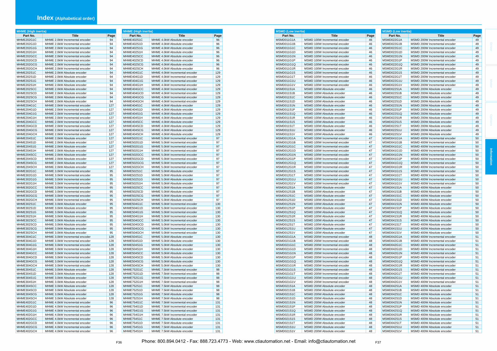
F36 F37
Index (Alphabetical order)
Driver
Mo
tor
Op
tion
sIn
form
ation
MHME (High inertia)Part No. Title Page
MHME202G1C MHME 2.0kW Incremental encoder 94MHME202G1D MHME 2.0kW Incremental encoder 94MHME202G1G MHME 2.0kW Incremental encoder 94MHME202G1H MHME 2.0kW Incremental encoder 94MHME202GCC MHME 2.0kW Incremental encoder 94MHME202GCD MHME 2.0kW Incremental encoder 94MHME202GCG MHME 2.0kW Incremental encoder 94MHME202GCH MHME 2.0kW Incremental encoder 94MHME202S1C MHME 2.0kW Absolute encoder 94MHME202S1D MHME 2.0kW Absolute encoder 94MHME202S1G MHME 2.0kW Absolute encoder 94MHME202S1H MHME 2.0kW Absolute encoder 94MHME202SCC MHME 2.0kW Absolute encoder 94MHME202SCD MHME 2.0kW Absolute encoder 94MHME202SCG MHME 2.0kW Absolute encoder 94MHME202SCH MHME 2.0kW Absolute encoder 94MHME204G1C MHME 2.0kW Incremental encoder 127MHME204G1D MHME 2.0kW Incremental encoder 127MHME204G1G MHME 2.0kW Incremental encoder 127MHME204G1H MHME 2.0kW Incremental encoder 127MHME204GCC MHME 2.0kW Incremental encoder 127MHME204GCD MHME 2.0kW Incremental encoder 127MHME204GCG MHME 2.0kW Incremental encoder 127MHME204GCH MHME 2.0kW Incremental encoder 127MHME204S1C MHME 2.0kW Absolute encoder 127MHME204S1D MHME 2.0kW Absolute encoder 127MHME204S1G MHME 2.0kW Absolute encoder 127MHME204S1H MHME 2.0kW Absolute encoder 127MHME204SCC MHME 2.0kW Absolute encoder 127MHME204SCD MHME 2.0kW Absolute encoder 127MHME204SCG MHME 2.0kW Absolute encoder 127MHME204SCH MHME 2.0kW Absolute encoder 127MHME302G1C MHME 3.0kW Incremental encoder 95MHME302G1D MHME 3.0kW Incremental encoder 95MHME302G1G MHME 3.0kW Incremental encoder 95MHME302G1H MHME 3.0kW Incremental encoder 95MHME302GCC MHME 3.0kW Incremental encoder 95MHME302GCD MHME 3.0kW Incremental encoder 95MHME302GCG MHME 3.0kW Incremental encoder 95MHME302GCH MHME 3.0kW Incremental encoder 95MHME302S1C MHME 3.0kW Absolute encoder 95MHME302S1D MHME 3.0kW Absolute encoder 95MHME302S1G MHME 3.0kW Absolute encoder 95MHME302S1H MHME 3.0kW Absolute encoder 95MHME302SCC MHME 3.0kW Absolute encoder 95MHME302SCD MHME 3.0kW Absolute encoder 95MHME302SCG MHME 3.0kW Absolute encoder 95MHME302SCH MHME 3.0kW Absolute encoder 95MHME304G1C MHME 3.0kW Incremental encoder 128MHME304G1D MHME 3.0kW Incremental encoder 128MHME304G1G MHME 3.0kW Incremental encoder 128MHME304G1H MHME 3.0kW Incremental encoder 128MHME304GCC MHME 3.0kW Incremental encoder 128MHME304GCD MHME 3.0kW Incremental encoder 128MHME304GCG MHME 3.0kW Incremental encoder 128MHME304GCH MHME 3.0kW Incremental encoder 128MHME304S1C MHME 3.0kW Absolute encoder 128MHME304S1D MHME 3.0kW Absolute encoder 128MHME304S1G MHME 3.0kW Absolute encoder 128MHME304S1H MHME 3.0kW Absolute encoder 128MHME304SCC MHME 3.0kW Absolute encoder 128MHME304SCD MHME 3.0kW Absolute encoder 128MHME304SCG MHME 3.0kW Absolute encoder 128MHME304SCH MHME 3.0kW Absolute encoder 128MHME402G1C MHME 4.0kW Incremental encoder 96MHME402G1D MHME 4.0kW Incremental encoder 96MHME402G1G MHME 4.0kW Incremental encoder 96MHME402G1H MHME 4.0kW Incremental encoder 96MHME402GCC MHME 4.0kW Incremental encoder 96MHME402GCD MHME 4.0kW Incremental encoder 96MHME402GCG MHME 4.0kW Incremental encoder 96MHME402GCH MHME 4.0kW Incremental encoder 96
MHME (High inertia)Part No. Title Page
MHME402S1C MHME 4.0kW Absolute encoder 96MHME402S1D MHME 4.0kW Absolute encoder 96MHME402S1G MHME 4.0kW Absolute encoder 96MHME402S1H MHME 4.0kW Absolute encoder 96MHME402SCC MHME 4.0kW Absolute encoder 96MHME402SCD MHME 4.0kW Absolute encoder 96MHME402SCG MHME 4.0kW Absolute encoder 96MHME402SCH MHME 4.0kW Absolute encoder 96MHME404G1C MHME 4.0kW Incremental encoder 129MHME404G1D MHME 4.0kW Incremental encoder 129MHME404G1G MHME 4.0kW Incremental encoder 129MHME404G1H MHME 4.0kW Incremental encoder 129MHME404GCC MHME 4.0kW Incremental encoder 129MHME404GCD MHME 4.0kW Incremental encoder 129MHME404GCG MHME 4.0kW Incremental encoder 129MHME404GCH MHME 4.0kW Incremental encoder 129MHME404S1C MHME 4.0kW Absolute encoder 129MHME404S1D MHME 4.0kW Absolute encoder 129MHME404S1G MHME 4.0kW Absolute encoder 129MHME404S1H MHME 4.0kW Absolute encoder 129MHME404SCC MHME 4.0kW Absolute encoder 129MHME404SCD MHME 4.0kW Absolute encoder 129MHME404SCG MHME 4.0kW Absolute encoder 129MHME404SCH MHME 4.0kW Absolute encoder 129MHME502G1C MHME 5.0kW Incremental encoder 97MHME502G1D MHME 5.0kW Incremental encoder 97MHME502G1G MHME 5.0kW Incremental encoder 97MHME502G1H MHME 5.0kW Incremental encoder 97MHME502GCC MHME 5.0kW Incremental encoder 97MHME502GCD MHME 5.0kW Incremental encoder 97MHME502GCG MHME 5.0kW Incremental encoder 97MHME502GCH MHME 5.0kW Incremental encoder 97MHME502S1C MHME 5.0kW Absolute encoder 97MHME502S1D MHME 5.0kW Absolute encoder 97MHME502S1G MHME 5.0kW Absolute encoder 97MHME502S1H MHME 5.0kW Absolute encoder 97MHME502SCC MHME 5.0kW Absolute encoder 97MHME502SCD MHME 5.0kW Absolute encoder 97MHME502SCG MHME 5.0kW Absolute encoder 97MHME502SCH MHME 5.0kW Absolute encoder 97MHME504G1C MHME 5.0kW Incremental encoder 130MHME504G1D MHME 5.0kW Incremental encoder 130MHME504G1G MHME 5.0kW Incremental encoder 130MHME504G1H MHME 5.0kW Incremental encoder 130MHME504GCC MHME 5.0kW Incremental encoder 130MHME504GCD MHME 5.0kW Incremental encoder 130MHME504GCG MHME 5.0kW Incremental encoder 130MHME504GCH MHME 5.0kW Incremental encoder 130MHME504S1C MHME 5.0kW Absolute encoder 130MHME504S1D MHME 5.0kW Absolute encoder 130MHME504S1G MHME 5.0kW Absolute encoder 130MHME504S1H MHME 5.0kW Absolute encoder 130MHME504SCC MHME 5.0kW Absolute encoder 130MHME504SCD MHME 5.0kW Absolute encoder 130MHME504SCG MHME 5.0kW Absolute encoder 130MHME504SCH MHME 5.0kW Absolute encoder 130MHME752G1C MHME 7.5kW Incremental encoder 98MHME752G1D MHME 7.5kW Incremental encoder 98MHME752G1G MHME 7.5kW Incremental encoder 98MHME752G1H MHME 7.5kW Incremental encoder 98MHME752S1C MHME 7.5kW Absolute encoder 98MHME752S1D MHME 7.5kW Absolute encoder 98MHME752S1G MHME 7.5kW Absolute encoder 98MHME752S1H MHME 7.5kW Absolute encoder 98MHME754G1C MHME 7.5kW Incremental encoder 131MHME754G1D MHME 7.5kW Incremental encoder 131MHME754G1G MHME 7.5kW Incremental encoder 131MHME754G1H MHME 7.5kW Incremental encoder 131MHME754S1C MHME 7.5kW Absolute encoder 131MHME754S1D MHME 7.5kW Absolute encoder 131MHME754S1G MHME 7.5kW Absolute encoder 131MHME754S1H MHME 7.5kW Absolute encoder 131
MSMD (Low inertia)Part No. Title Page
MSMD011G1A MSMD 100W Incremental encoder 46MSMD011G1B MSMD 100W Incremental encoder 46MSMD011G1C MSMD 100W Incremental encoder 46MSMD011G1D MSMD 100W Incremental encoder 46MSMD011G1N MSMD 100W Incremental encoder 46MSMD011G1P MSMD 100W Incremental encoder 46MSMD011G1Q MSMD 100W Incremental encoder 46MSMD011G1R MSMD 100W Incremental encoder 46MSMD011G1S MSMD 100W Incremental encoder 46MSMD011G1T MSMD 100W Incremental encoder 46MSMD011G1U MSMD 100W Incremental encoder 46MSMD011G1V MSMD 100W Incremental encoder 46MSMD011S1A MSMD 100W Absolute encoder 46MSMD011S1B MSMD 100W Absolute encoder 46MSMD011S1C MSMD 100W Absolute encoder 46MSMD011S1D MSMD 100W Absolute encoder 46MSMD011S1N MSMD 100W Absolute encoder 46MSMD011S1P MSMD 100W Absolute encoder 46MSMD011S1Q MSMD 100W Absolute encoder 46MSMD011S1R MSMD 100W Absolute encoder 46MSMD011S1S MSMD 100W Absolute encoder 46MSMD011S1T MSMD 100W Absolute encoder 46MSMD011S1U MSMD 100W Absolute encoder 46MSMD011S1V MSMD 100W Absolute encoder 46MSMD012G1A MSMD 100W Incremental encoder 47MSMD012G1B MSMD 100W Incremental encoder 47MSMD012G1C MSMD 100W Incremental encoder 47MSMD012G1D MSMD 100W Incremental encoder 47MSMD012G1N MSMD 100W Incremental encoder 47MSMD012G1P MSMD 100W Incremental encoder 47MSMD012G1Q MSMD 100W Incremental encoder 47MSMD012G1R MSMD 100W Incremental encoder 47MSMD012G1S MSMD 100W Incremental encoder 47MSMD012G1T MSMD 100W Incremental encoder 47MSMD012G1U MSMD 100W Incremental encoder 47MSMD012G1V MSMD 100W Incremental encoder 47MSMD012S1A MSMD 100W Absolute encoder 47MSMD012S1B MSMD 100W Absolute encoder 47MSMD012S1C MSMD 100W Absolute encoder 47MSMD012S1D MSMD 100W Absolute encoder 47MSMD012S1N MSMD 100W Absolute encoder 47MSMD012S1P MSMD 100W Absolute encoder 47MSMD012S1Q MSMD 100W Absolute encoder 47MSMD012S1R MSMD 100W Absolute encoder 47MSMD012S1S MSMD 100W Absolute encoder 47MSMD012S1T MSMD 100W Absolute encoder 47MSMD012S1U MSMD 100W Absolute encoder 47MSMD012S1V MSMD 100W Absolute encoder 47MSMD021G1A MSMD 200W Incremental encoder 48MSMD021G1B MSMD 200W Incremental encoder 48MSMD021G1C MSMD 200W Incremental encoder 48MSMD021G1D MSMD 200W Incremental encoder 48MSMD021G1N MSMD 200W Incremental encoder 48MSMD021G1P MSMD 200W Incremental encoder 48MSMD021G1Q MSMD 200W Incremental encoder 48MSMD021G1R MSMD 200W Incremental encoder 48MSMD021G1S MSMD 200W Incremental encoder 48MSMD021G1T MSMD 200W Incremental encoder 48MSMD021G1U MSMD 200W Incremental encoder 48MSMD021G1V MSMD 200W Incremental encoder 48MSMD021S1A MSMD 200W Absolute encoder 48MSMD021S1B MSMD 200W Absolute encoder 48MSMD021S1C MSMD 200W Absolute encoder 48MSMD021S1D MSMD 200W Absolute encoder 48MSMD021S1N MSMD 200W Absolute encoder 48MSMD021S1P MSMD 200W Absolute encoder 48MSMD021S1Q MSMD 200W Absolute encoder 48MSMD021S1R MSMD 200W Absolute encoder 48MSMD021S1S MSMD 200W Absolute encoder 48MSMD021S1T MSMD 200W Absolute encoder 48MSMD021S1U MSMD 200W Absolute encoder 48MSMD021S1V MSMD 200W Absolute encoder 48
MSMD (Low inertia)Part No. Title Page
MSMD022G1A MSMD 200W Incremental encoder 49MSMD022G1B MSMD 200W Incremental encoder 49MSMD022G1C MSMD 200W Incremental encoder 49MSMD022G1D MSMD 200W Incremental encoder 49MSMD022G1N MSMD 200W Incremental encoder 49MSMD022G1P MSMD 200W Incremental encoder 49MSMD022G1Q MSMD 200W Incremental encoder 49MSMD022G1R MSMD 200W Incremental encoder 49MSMD022G1S MSMD 200W Incremental encoder 49MSMD022G1T MSMD 200W Incremental encoder 49MSMD022G1U MSMD 200W Incremental encoder 49MSMD022G1V MSMD 200W Incremental encoder 49MSMD022S1A MSMD 200W Absolute encoder 49MSMD022S1B MSMD 200W Absolute encoder 49MSMD022S1C MSMD 200W Absolute encoder 49MSMD022S1D MSMD 200W Absolute encoder 49MSMD022S1N MSMD 200W Absolute encoder 49MSMD022S1P MSMD 200W Absolute encoder 49MSMD022S1Q MSMD 200W Absolute encoder 49MSMD022S1R MSMD 200W Absolute encoder 49MSMD022S1S MSMD 200W Absolute encoder 49MSMD022S1T MSMD 200W Absolute encoder 49MSMD022S1U MSMD 200W Absolute encoder 49MSMD022S1V MSMD 200W Absolute encoder 49MSMD041G1A MSMD 400W Incremental encoder 50MSMD041G1B MSMD 400W Incremental encoder 50MSMD041G1C MSMD 400W Incremental encoder 50MSMD041G1D MSMD 400W Incremental encoder 50MSMD041G1N MSMD 400W Incremental encoder 50MSMD041G1P MSMD 400W Incremental encoder 50MSMD041G1Q MSMD 400W Incremental encoder 50MSMD041G1R MSMD 400W Incremental encoder 50MSMD041G1S MSMD 400W Incremental encoder 50MSMD041G1T MSMD 400W Incremental encoder 50MSMD041G1U MSMD 400W Incremental encoder 50MSMD041G1V MSMD 400W Incremental encoder 50MSMD041S1A MSMD 400W Absolute encoder 50MSMD041S1B MSMD 400W Absolute encoder 50MSMD041S1C MSMD 400W Absolute encoder 50MSMD041S1D MSMD 400W Absolute encoder 50MSMD041S1N MSMD 400W Absolute encoder 50MSMD041S1P MSMD 400W Absolute encoder 50MSMD041S1Q MSMD 400W Absolute encoder 50MSMD041S1R MSMD 400W Absolute encoder 50MSMD041S1S MSMD 400W Absolute encoder 50MSMD041S1T MSMD 400W Absolute encoder 50MSMD041S1U MSMD 400W Absolute encoder 50MSMD041S1V MSMD 400W Absolute encoder 50MSMD042G1A MSMD 400W Incremental encoder 51MSMD042G1B MSMD 400W Incremental encoder 51MSMD042G1C MSMD 400W Incremental encoder 51MSMD042G1D MSMD 400W Incremental encoder 51MSMD042G1N MSMD 400W Incremental encoder 51MSMD042G1P MSMD 400W Incremental encoder 51MSMD042G1Q MSMD 400W Incremental encoder 51MSMD042G1R MSMD 400W Incremental encoder 51MSMD042G1S MSMD 400W Incremental encoder 51MSMD042G1T MSMD 400W Incremental encoder 51MSMD042G1U MSMD 400W Incremental encoder 51MSMD042G1V MSMD 400W Incremental encoder 51MSMD042S1A MSMD 400W Absolute encoder 51MSMD042S1B MSMD 400W Absolute encoder 51MSMD042S1C MSMD 400W Absolute encoder 51MSMD042S1D MSMD 400W Absolute encoder 51MSMD042S1N MSMD 400W Absolute encoder 51MSMD042S1P MSMD 400W Absolute encoder 51MSMD042S1Q MSMD 400W Absolute encoder 51MSMD042S1R MSMD 400W Absolute encoder 51MSMD042S1S MSMD 400W Absolute encoder 51MSMD042S1T MSMD 400W Absolute encoder 51MSMD042S1U MSMD 400W Absolute encoder 51MSMD042S1V MSMD 400W Absolute encoder 51
Phone: 800.894.0412 - Fax: 888.723.4773 - Web: www.ctiautomation.net - Email: [email protected]
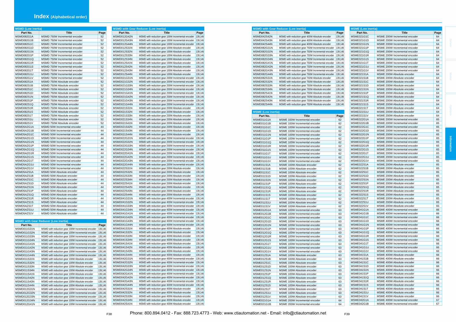
F38 F39
Index (Alphabetical order)
Driver
Mo
tor
Op
tion
sIn
form
ation
MSME (Low inertia)Part No. Title Page
MSME021G1C MSME 200W Incremental encoder 64MSME021G1D MSME 200W Incremental encoder 64MSME021G1N MSME 200W Incremental encoder 64MSME021G1P MSME 200W Incremental encoder 64MSME021G1Q MSME 200W Incremental encoder 64MSME021G1R MSME 200W Incremental encoder 64MSME021G1S MSME 200W Incremental encoder 64MSME021G1T MSME 200W Incremental encoder 64MSME021G1U MSME 200W Incremental encoder 64MSME021G1V MSME 200W Incremental encoder 64MSME021S1A MSME 200W Absolute encoder 64MSME021S1B MSME 200W Absolute encoder 64MSME021S1C MSME 200W Absolute encoder 64MSME021S1D MSME 200W Absolute encoder 64MSME021S1N MSME 200W Absolute encoder 64MSME021S1P MSME 200W Absolute encoder 64MSME021S1Q MSME 200W Absolute encoder 64MSME021S1R MSME 200W Absolute encoder 64MSME021S1S MSME 200W Absolute encoder 64MSME021S1T MSME 200W Absolute encoder 64MSME021S1U MSME 200W Absolute encoder 64MSME021S1V MSME 200W Absolute encoder 64MSME022G1A MSME 200W Incremental encoder 65MSME022G1B MSME 200W Incremental encoder 65MSME022G1C MSME 200W Incremental encoder 65MSME022G1D MSME 200W Incremental encoder 65MSME022G1N MSME 200W Incremental encoder 65MSME022G1P MSME 200W Incremental encoder 65MSME022G1Q MSME 200W Incremental encoder 65MSME022G1R MSME 200W Incremental encoder 65MSME022G1S MSME 200W Incremental encoder 65MSME022G1T MSME 200W Incremental encoder 65MSME022G1U MSME 200W Incremental encoder 65MSME022G1V MSME 200W Incremental encoder 65MSME022S1A MSME 200W Absolute encoder 65MSME022S1B MSME 200W Absolute encoder 65MSME022S1C MSME 200W Absolute encoder 65MSME022S1D MSME 200W Absolute encoder 65MSME022S1N MSME 200W Absolute encoder 65MSME022S1P MSME 200W Absolute encoder 65MSME022S1Q MSME 200W Absolute encoder 65MSME022S1R MSME 200W Absolute encoder 65MSME022S1S MSME 200W Absolute encoder 65MSME022S1T MSME 200W Absolute encoder 65MSME022S1U MSME 200W Absolute encoder 65MSME022S1V MSME 200W Absolute encoder 65MSME041G1A MSME 400W Incremental encoder 66MSME041G1B MSME 400W Incremental encoder 66MSME041G1C MSME 400W Incremental encoder 66MSME041G1D MSME 400W Incremental encoder 66MSME041G1N MSME 400W Incremental encoder 66MSME041G1P MSME 400W Incremental encoder 66MSME041G1Q MSME 400W Incremental encoder 66MSME041G1R MSME 400W Incremental encoder 66MSME041G1S MSME 400W Incremental encoder 66MSME041G1T MSME 400W Incremental encoder 66MSME041G1U MSME 400W Incremental encoder 66MSME041G1V MSME 400W Incremental encoder 66MSME041S1A MSME 400W Absolute encoder 66MSME041S1B MSME 400W Absolute encoder 66MSME041S1C MSME 400W Absolute encoder 66MSME041S1D MSME 400W Absolute encoder 66MSME041S1N MSME 400W Absolute encoder 66MSME041S1P MSME 400W Absolute encoder 66MSME041S1Q MSME 400W Absolute encoder 66MSME041S1R MSME 400W Absolute encoder 66MSME041S1S MSME 400W Absolute encoder 66MSME041S1T MSME 400W Absolute encoder 66MSME041S1U MSME 400W Absolute encoder 66MSME041S1V MSME 400W Absolute encoder 66MSME042G1A MSME 400W Incremental encoder 67MSME042G1B MSME 400W Incremental encoder 67
MSMD with Gear Reducer (Low inertia)Part No. Title Page
MSMD042S42N MSMD with reduction gear 400W Absolute encoder 139,146MSMD042S43N MSMD with reduction gear 400W Absolute encoder 139,146MSMD042S44N MSMD with reduction gear 400W Absolute encoder 139,146MSMD082G31N MSMD with reduction gear 750W Incremental encoder 139,146MSMD082G32N MSMD with reduction gear 750W Incremental encoder 139,146MSMD082G33N MSMD with reduction gear 750W Incremental encoder 139,146MSMD082G34N MSMD with reduction gear 750W Incremental encoder 139,146MSMD082G41N MSMD with reduction gear 750W Incremental encoder 139,146MSMD082G42N MSMD with reduction gear 750W Incremental encoder 139,146MSMD082G43N MSMD with reduction gear 750W Incremental encoder 139,146MSMD082G44N MSMD with reduction gear 750W Incremental encoder 139,146MSMD082S31N MSMD with reduction gear 750W Absolute encoder 139,146MSMD082S32N MSMD with reduction gear 750W Absolute encoder 139,146MSMD082S33N MSMD with reduction gear 750W Absolute encoder 139,146MSMD082S34N MSMD with reduction gear 750W Absolute encoder 139,146MSMD082S41N MSMD with reduction gear 750W Absolute encoder 139,146MSMD082S42N MSMD with reduction gear 750W Absolute encoder 139,146MSMD082S43N MSMD with reduction gear 750W Absolute encoder 139,146MSMD082S44N MSMD with reduction gear 750W Absolute encoder 139,146
MSME (Low inertia)Part No. Title Page
MSME011G1A MSME 100W Incremental encoder 62MSME011G1B MSME 100W Incremental encoder 62MSME011G1C MSME 100W Incremental encoder 62MSME011G1D MSME 100W Incremental encoder 62MSME011G1N MSME 100W Incremental encoder 62MSME011G1P MSME 100W Incremental encoder 62MSME011G1Q MSME 100W Incremental encoder 62MSME011G1R MSME 100W Incremental encoder 62MSME011G1S MSME 100W Incremental encoder 62MSME011G1T MSME 100W Incremental encoder 62MSME011G1U MSME 100W Incremental encoder 62MSME011G1V MSME 100W Incremental encoder 62MSME011S1A MSME 100W Absolute encoder 62MSME011S1B MSME 100W Absolute encoder 62MSME011S1C MSME 100W Absolute encoder 62MSME011S1D MSME 100W Absolute encoder 62MSME011S1N MSME 100W Absolute encoder 62MSME011S1P MSME 100W Absolute encoder 62MSME011S1Q MSME 100W Absolute encoder 62MSME011S1R MSME 100W Absolute encoder 62MSME011S1S MSME 100W Absolute encoder 62MSME011S1T MSME 100W Absolute encoder 62MSME011S1U MSME 100W Absolute encoder 62MSME011S1V MSME 100W Absolute encoder 62MSME012G1A MSME 100W Incremental encoder 63MSME012G1B MSME 100W Incremental encoder 63MSME012G1C MSME 100W Incremental encoder 63MSME012G1D MSME 100W Incremental encoder 63MSME012G1N MSME 100W Incremental encoder 63MSME012G1P MSME 100W Incremental encoder 63MSME012G1Q MSME 100W Incremental encoder 63MSME012G1R MSME 100W Incremental encoder 63MSME012G1S MSME 100W Incremental encoder 63MSME012G1T MSME 100W Incremental encoder 63MSME012G1U MSME 100W Incremental encoder 63MSME012G1V MSME 100W Incremental encoder 63MSME012S1A MSME 100W Absolute encoder 63MSME012S1B MSME 100W Absolute encoder 63MSME012S1C MSME 100W Absolute encoder 63MSME012S1D MSME 100W Absolute encoder 63MSME012S1N MSME 100W Absolute encoder 63MSME012S1P MSME 100W Absolute encoder 63MSME012S1Q MSME 100W Absolute encoder 63MSME012S1R MSME 100W Absolute encoder 63MSME012S1S MSME 100W Absolute encoder 63MSME012S1T MSME 100W Absolute encoder 63MSME012S1U MSME 100W Absolute encoder 63MSME012S1V MSME 100W Absolute encoder 63MSME021G1A MSME 200W Incremental encoder 64MSME021G1B MSME 200W Incremental encoder 64
MSMD with Gear Reducer (Low inertia)Part No. Title Page
MSMD012G42N MSMD with reduction gear 100W Incremental encoder 139,146MSMD012G43N MSMD with reduction gear 100W Incremental encoder 139,146MSMD012G44N MSMD with reduction gear 100W Incremental encoder 139,146MSMD012S31N MSMD with reduction gear 100W Absolute encoder 139,146MSMD012S32N MSMD with reduction gear 100W Absolute encoder 139,146MSMD012S33N MSMD with reduction gear 100W Absolute encoder 139,146MSMD012S34N MSMD with reduction gear 100W Absolute encoder 139,146MSMD012S41N MSMD with reduction gear 100W Absolute encoder 139,146MSMD012S42N MSMD with reduction gear 100W Absolute encoder 139,146MSMD012S43N MSMD with reduction gear 100W Absolute encoder 139,146MSMD012S44N MSMD with reduction gear 100W Absolute encoder 139,146MSMD021G31N MSMD with reduction gear 200W Incremental encoder 139,146MSMD021G32N MSMD with reduction gear 200W Incremental encoder 139,146MSMD021G33N MSMD with reduction gear 200W Incremental encoder 139,146MSMD021G34N MSMD with reduction gear 200W Incremental encoder 139,146MSMD021G41N MSMD with reduction gear 200W Incremental encoder 139,146MSMD021G42N MSMD with reduction gear 200W Incremental encoder 139,146MSMD021G43N MSMD with reduction gear 200W Incremental encoder 139,146MSMD021G44N MSMD with reduction gear 200W Incremental encoder 139,146MSMD021S31N MSMD with reduction gear 200W Absolute encoder 139,146MSMD021S32N MSMD with reduction gear 200W Absolute encoder 139,146MSMD021S33N MSMD with reduction gear 200W Absolute encoder 139,146MSMD021S34N MSMD with reduction gear 200W Absolute encoder 139,146MSMD021S41N MSMD with reduction gear 200W Absolute encoder 139,146MSMD021S42N MSMD with reduction gear 200W Absolute encoder 139,146MSMD021S43N MSMD with reduction gear 200W Absolute encoder 139,146MSMD021S44N MSMD with reduction gear 200W Absolute encoder 139,146MSMD022G31N MSMD with reduction gear 200W Incremental encoder 139,146MSMD022G32N MSMD with reduction gear 200W Incremental encoder 139,146MSMD022G33N MSMD with reduction gear 200W Incremental encoder 139,146MSMD022G34N MSMD with reduction gear 200W Incremental encoder 139,146MSMD022G41N MSMD with reduction gear 200W Incremental encoder 139,146MSMD022G42N MSMD with reduction gear 200W Incremental encoder 139,146MSMD022G43N MSMD with reduction gear 200W Incremental encoder 139,146MSMD022G44N MSMD with reduction gear 200W Incremental encoder 139,146MSMD022S31N MSMD with reduction gear 200W Absolute encoder 139,146MSMD022S32N MSMD with reduction gear 200W Absolute encoder 139,146MSMD022S33N MSMD with reduction gear 200W Absolute encoder 139,146MSMD022S34N MSMD with reduction gear 200W Absolute encoder 139,146MSMD022S41N MSMD with reduction gear 200W Absolute encoder 139,146MSMD022S42N MSMD with reduction gear 200W Absolute encoder 139,146MSMD022S43N MSMD with reduction gear 200W Absolute encoder 139,146MSMD022S44N MSMD with reduction gear 200W Absolute encoder 139,146MSMD041G31N MSMD with reduction gear 400W Incremental encoder 139,146MSMD041G32N MSMD with reduction gear 400W Incremental encoder 139,146MSMD041G33N MSMD with reduction gear 400W Incremental encoder 139,146MSMD041G34N MSMD with reduction gear 400W Incremental encoder 139,146MSMD041G41N MSMD with reduction gear 400W Incremental encoder 139,146MSMD041G42N MSMD with reduction gear 400W Incremental encoder 139,146MSMD041G43N MSMD with reduction gear 400W Incremental encoder 139,146MSMD041G44N MSMD with reduction gear 400W Incremental encoder 139,146MSMD041S31N MSMD with reduction gear 400W Absolute encoder 139,146MSMD041S32N MSMD with reduction gear 400W Absolute encoder 139,146MSMD041S33N MSMD with reduction gear 400W Absolute encoder 139,146MSMD041S34N MSMD with reduction gear 400W Absolute encoder 139,146MSMD041S41N MSMD with reduction gear 400W Absolute encoder 139,146MSMD041S42N MSMD with reduction gear 400W Absolute encoder 139,146MSMD041S43N MSMD with reduction gear 400W Absolute encoder 139,146MSMD041S44N MSMD with reduction gear 400W Absolute encoder 139,146MSMD042G31N MSMD with reduction gear 400W Incremental encoder 139,146MSMD042G32N MSMD with reduction gear 400W Incremental encoder 139,146MSMD042G33N MSMD with reduction gear 400W Incremental encoder 139,146MSMD042G34N MSMD with reduction gear 400W Incremental encoder 139,146MSMD042G41N MSMD with reduction gear 400W Incremental encoder 139,146MSMD042G42N MSMD with reduction gear 400W Incremental encoder 139,146MSMD042G43N MSMD with reduction gear 400W Incremental encoder 139,146MSMD042G44N MSMD with reduction gear 400W Incremental encoder 139,146MSMD042S31N MSMD with reduction gear 400W Absolute encoder 139,146MSMD042S32N MSMD with reduction gear 400W Absolute encoder 139,146MSMD042S33N MSMD with reduction gear 400W Absolute encoder 139,146MSMD042S34N MSMD with reduction gear 400W Absolute encoder 139,146MSMD042S41N MSMD with reduction gear 400W Absolute encoder 139,146
MSMD (Low inertia)Part No. Title Page
MSMD082G1A MSMD 750W Incremental encoder 52MSMD082G1B MSMD 750W Incremental encoder 52MSMD082G1C MSMD 750W Incremental encoder 52MSMD082G1D MSMD 750W Incremental encoder 52MSMD082G1N MSMD 750W Incremental encoder 52MSMD082G1P MSMD 750W Incremental encoder 52MSMD082G1Q MSMD 750W Incremental encoder 52MSMD082G1R MSMD 750W Incremental encoder 52MSMD082G1S MSMD 750W Incremental encoder 52MSMD082G1T MSMD 750W Incremental encoder 52MSMD082G1U MSMD 750W Incremental encoder 52MSMD082G1V MSMD 750W Incremental encoder 52MSMD082S1A MSMD 750W Absolute encoder 52MSMD082S1B MSMD 750W Absolute encoder 52MSMD082S1C MSMD 750W Absolute encoder 52MSMD082S1D MSMD 750W Absolute encoder 52MSMD082S1N MSMD 750W Absolute encoder 52MSMD082S1P MSMD 750W Absolute encoder 52MSMD082S1Q MSMD 750W Absolute encoder 52MSMD082S1R MSMD 750W Absolute encoder 52MSMD082S1S MSMD 750W Absolute encoder 52MSMD082S1T MSMD 750W Absolute encoder 52MSMD082S1U MSMD 750W Absolute encoder 52MSMD082S1V MSMD 750W Absolute encoder 52MSMD5AZG1A MSMD 50W Incremental encoder 44MSMD5AZG1B MSMD 50W Incremental encoder 44MSMD5AZG1C MSMD 50W Incremental encoder 44MSMD5AZG1D MSMD 50W Incremental encoder 44MSMD5AZG1N MSMD 50W Incremental encoder 44MSMD5AZG1P MSMD 50W Incremental encoder 44MSMD5AZG1Q MSMD 50W Incremental encoder 44MSMD5AZG1R MSMD 50W Incremental encoder 44MSMD5AZG1S MSMD 50W Incremental encoder 44MSMD5AZG1T MSMD 50W Incremental encoder 44MSMD5AZG1U MSMD 50W Incremental encoder 44MSMD5AZG1V MSMD 50W Incremental encoder 44MSMD5AZS1A MSMD 50W Absolute encoder 44MSMD5AZS1B MSMD 50W Absolute encoder 44MSMD5AZS1C MSMD 50W Absolute encoder 44MSMD5AZS1D MSMD 50W Absolute encoder 44MSMD5AZS1N MSMD 50W Absolute encoder 44MSMD5AZS1P MSMD 50W Absolute encoder 44MSMD5AZS1Q MSMD 50W Absolute encoder 44MSMD5AZS1R MSMD 50W Absolute encoder 44MSMD5AZS1S MSMD 50W Absolute encoder 44MSMD5AZS1T MSMD 50W Absolute encoder 44MSMD5AZS1U MSMD 50W Absolute encoder 44MSMD5AZS1V MSMD 50W Absolute encoder 44
MSMD with Gear Reducer (Low inertia)Part No. Title Page
MSMD011G31N MSMD with reduction gear 100W Incremental encoder 139,146MSMD011G32N MSMD with reduction gear 100W Incremental encoder 139,146MSMD011G33N MSMD with reduction gear 100W Incremental encoder 139,146MSMD011G34N MSMD with reduction gear 100W Incremental encoder 139,146MSMD011G41N MSMD with reduction gear 100W Incremental encoder 139,146MSMD011G42N MSMD with reduction gear 100W Incremental encoder 139,146MSMD011G43N MSMD with reduction gear 100W Incremental encoder 139,146MSMD011G44N MSMD with reduction gear 100W Incremental encoder 139,146MSMD011S31N MSMD with reduction gear 100W Absolute encoder 139,146MSMD011S32N MSMD with reduction gear 100W Absolute encoder 139,146MSMD011S33N MSMD with reduction gear 100W Absolute encoder 139,146MSMD011S34N MSMD with reduction gear 100W Absolute encoder 139,146MSMD011S41N MSMD with reduction gear 100W Absolute encoder 139,146MSMD011S42N MSMD with reduction gear 100W Absolute encoder 139,146MSMD011S43N MSMD with reduction gear 100W Absolute encoder 139,146MSMD011S44N MSMD with reduction gear 100W Absolute encoder 139,146MSMD012G31N MSMD with reduction gear 100W Incremental encoder 139,146MSMD012G32N MSMD with reduction gear 100W Incremental encoder 139,146MSMD012G33N MSMD with reduction gear 100W Incremental encoder 139,146MSMD012G34N MSMD with reduction gear 100W Incremental encoder 139,146MSMD012G41N MSMD with reduction gear 100W Incremental encoder 139,146
Phone: 800.894.0412 - Fax: 888.723.4773 - Web: www.ctiautomation.net - Email: [email protected]
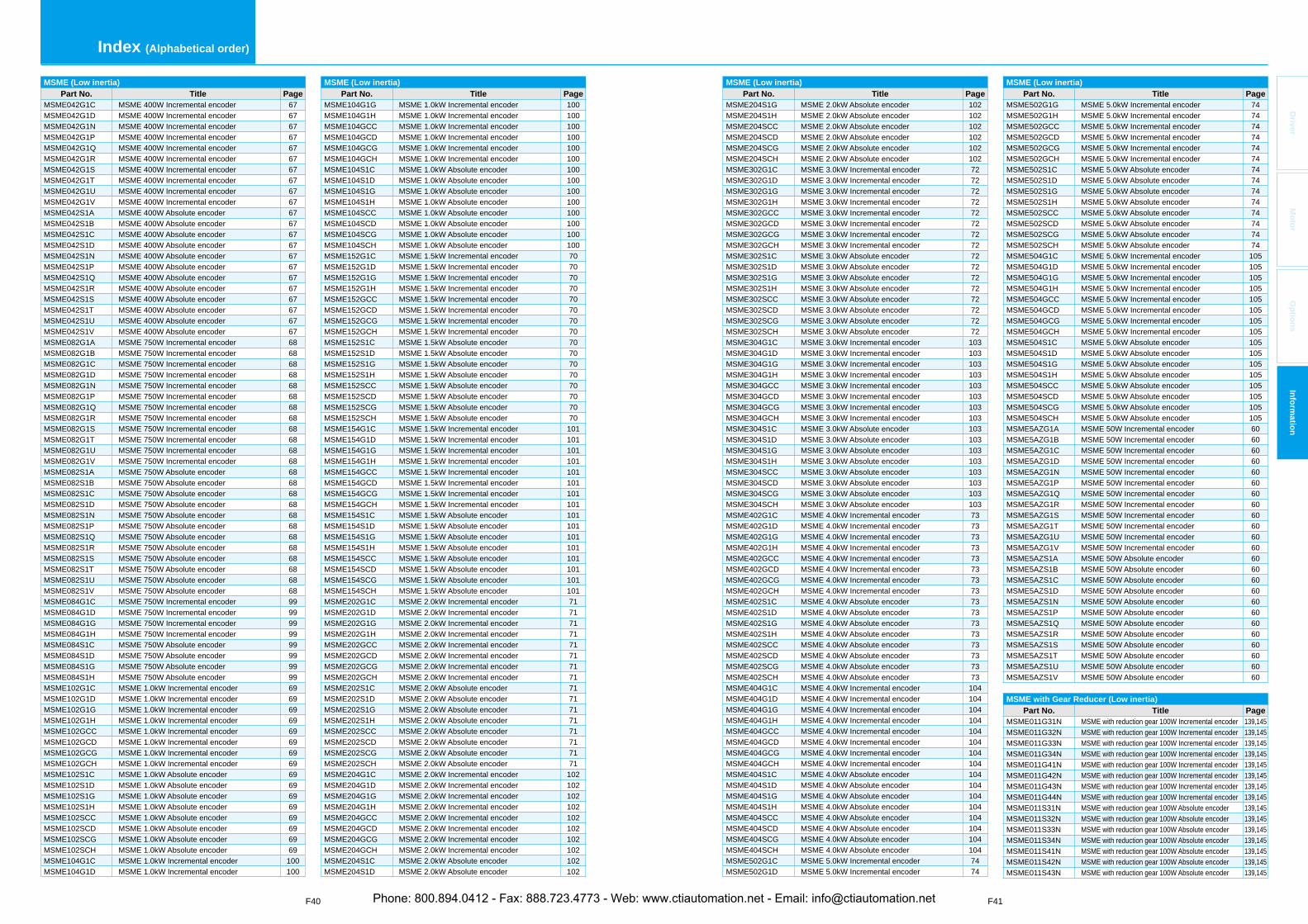
F40 F41
Index (Alphabetical order)
Driver
Mo
tor
Op
tion
sIn
form
ation
MSME (Low inertia)Part No. Title Page
MSME042G1C MSME 400W Incremental encoder 67MSME042G1D MSME 400W Incremental encoder 67MSME042G1N MSME 400W Incremental encoder 67MSME042G1P MSME 400W Incremental encoder 67MSME042G1Q MSME 400W Incremental encoder 67MSME042G1R MSME 400W Incremental encoder 67MSME042G1S MSME 400W Incremental encoder 67MSME042G1T MSME 400W Incremental encoder 67MSME042G1U MSME 400W Incremental encoder 67MSME042G1V MSME 400W Incremental encoder 67MSME042S1A MSME 400W Absolute encoder 67MSME042S1B MSME 400W Absolute encoder 67MSME042S1C MSME 400W Absolute encoder 67MSME042S1D MSME 400W Absolute encoder 67MSME042S1N MSME 400W Absolute encoder 67MSME042S1P MSME 400W Absolute encoder 67MSME042S1Q MSME 400W Absolute encoder 67MSME042S1R MSME 400W Absolute encoder 67MSME042S1S MSME 400W Absolute encoder 67MSME042S1T MSME 400W Absolute encoder 67MSME042S1U MSME 400W Absolute encoder 67MSME042S1V MSME 400W Absolute encoder 67MSME082G1A MSME 750W Incremental encoder 68MSME082G1B MSME 750W Incremental encoder 68MSME082G1C MSME 750W Incremental encoder 68MSME082G1D MSME 750W Incremental encoder 68MSME082G1N MSME 750W Incremental encoder 68MSME082G1P MSME 750W Incremental encoder 68MSME082G1Q MSME 750W Incremental encoder 68MSME082G1R MSME 750W Incremental encoder 68MSME082G1S MSME 750W Incremental encoder 68MSME082G1T MSME 750W Incremental encoder 68MSME082G1U MSME 750W Incremental encoder 68MSME082G1V MSME 750W Incremental encoder 68MSME082S1A MSME 750W Absolute encoder 68MSME082S1B MSME 750W Absolute encoder 68MSME082S1C MSME 750W Absolute encoder 68MSME082S1D MSME 750W Absolute encoder 68MSME082S1N MSME 750W Absolute encoder 68MSME082S1P MSME 750W Absolute encoder 68MSME082S1Q MSME 750W Absolute encoder 68MSME082S1R MSME 750W Absolute encoder 68MSME082S1S MSME 750W Absolute encoder 68MSME082S1T MSME 750W Absolute encoder 68MSME082S1U MSME 750W Absolute encoder 68MSME082S1V MSME 750W Absolute encoder 68MSME084G1C MSME 750W Incremental encoder 99MSME084G1D MSME 750W Incremental encoder 99MSME084G1G MSME 750W Incremental encoder 99MSME084G1H MSME 750W Incremental encoder 99MSME084S1C MSME 750W Absolute encoder 99MSME084S1D MSME 750W Absolute encoder 99MSME084S1G MSME 750W Absolute encoder 99MSME084S1H MSME 750W Absolute encoder 99MSME102G1C MSME 1.0kW Incremental encoder 69MSME102G1D MSME 1.0kW Incremental encoder 69MSME102G1G MSME 1.0kW Incremental encoder 69MSME102G1H MSME 1.0kW Incremental encoder 69MSME102GCC MSME 1.0kW Incremental encoder 69MSME102GCD MSME 1.0kW Incremental encoder 69MSME102GCG MSME 1.0kW Incremental encoder 69MSME102GCH MSME 1.0kW Incremental encoder 69MSME102S1C MSME 1.0kW Absolute encoder 69MSME102S1D MSME 1.0kW Absolute encoder 69MSME102S1G MSME 1.0kW Absolute encoder 69MSME102S1H MSME 1.0kW Absolute encoder 69MSME102SCC MSME 1.0kW Absolute encoder 69MSME102SCD MSME 1.0kW Absolute encoder 69MSME102SCG MSME 1.0kW Absolute encoder 69MSME102SCH MSME 1.0kW Absolute encoder 69MSME104G1C MSME 1.0kW Incremental encoder 100MSME104G1D MSME 1.0kW Incremental encoder 100
MSME (Low inertia)Part No. Title Page
MSME104G1G MSME 1.0kW Incremental encoder 100MSME104G1H MSME 1.0kW Incremental encoder 100MSME104GCC MSME 1.0kW Incremental encoder 100MSME104GCD MSME 1.0kW Incremental encoder 100MSME104GCG MSME 1.0kW Incremental encoder 100MSME104GCH MSME 1.0kW Incremental encoder 100MSME104S1C MSME 1.0kW Absolute encoder 100MSME104S1D MSME 1.0kW Absolute encoder 100MSME104S1G MSME 1.0kW Absolute encoder 100MSME104S1H MSME 1.0kW Absolute encoder 100MSME104SCC MSME 1.0kW Absolute encoder 100MSME104SCD MSME 1.0kW Absolute encoder 100MSME104SCG MSME 1.0kW Absolute encoder 100MSME104SCH MSME 1.0kW Absolute encoder 100MSME152G1C MSME 1.5kW Incremental encoder 70MSME152G1D MSME 1.5kW Incremental encoder 70MSME152G1G MSME 1.5kW Incremental encoder 70MSME152G1H MSME 1.5kW Incremental encoder 70MSME152GCC MSME 1.5kW Incremental encoder 70MSME152GCD MSME 1.5kW Incremental encoder 70MSME152GCG MSME 1.5kW Incremental encoder 70MSME152GCH MSME 1.5kW Incremental encoder 70MSME152S1C MSME 1.5kW Absolute encoder 70MSME152S1D MSME 1.5kW Absolute encoder 70MSME152S1G MSME 1.5kW Absolute encoder 70MSME152S1H MSME 1.5kW Absolute encoder 70MSME152SCC MSME 1.5kW Absolute encoder 70MSME152SCD MSME 1.5kW Absolute encoder 70MSME152SCG MSME 1.5kW Absolute encoder 70MSME152SCH MSME 1.5kW Absolute encoder 70MSME154G1C MSME 1.5kW Incremental encoder 101MSME154G1D MSME 1.5kW Incremental encoder 101MSME154G1G MSME 1.5kW Incremental encoder 101MSME154G1H MSME 1.5kW Incremental encoder 101MSME154GCC MSME 1.5kW Incremental encoder 101MSME154GCD MSME 1.5kW Incremental encoder 101MSME154GCG MSME 1.5kW Incremental encoder 101MSME154GCH MSME 1.5kW Incremental encoder 101MSME154S1C MSME 1.5kW Absolute encoder 101MSME154S1D MSME 1.5kW Absolute encoder 101MSME154S1G MSME 1.5kW Absolute encoder 101MSME154S1H MSME 1.5kW Absolute encoder 101MSME154SCC MSME 1.5kW Absolute encoder 101MSME154SCD MSME 1.5kW Absolute encoder 101MSME154SCG MSME 1.5kW Absolute encoder 101MSME154SCH MSME 1.5kW Absolute encoder 101MSME202G1C MSME 2.0kW Incremental encoder 71MSME202G1D MSME 2.0kW Incremental encoder 71MSME202G1G MSME 2.0kW Incremental encoder 71MSME202G1H MSME 2.0kW Incremental encoder 71MSME202GCC MSME 2.0kW Incremental encoder 71MSME202GCD MSME 2.0kW Incremental encoder 71MSME202GCG MSME 2.0kW Incremental encoder 71MSME202GCH MSME 2.0kW Incremental encoder 71MSME202S1C MSME 2.0kW Absolute encoder 71MSME202S1D MSME 2.0kW Absolute encoder 71MSME202S1G MSME 2.0kW Absolute encoder 71MSME202S1H MSME 2.0kW Absolute encoder 71MSME202SCC MSME 2.0kW Absolute encoder 71MSME202SCD MSME 2.0kW Absolute encoder 71MSME202SCG MSME 2.0kW Absolute encoder 71MSME202SCH MSME 2.0kW Absolute encoder 71MSME204G1C MSME 2.0kW Incremental encoder 102MSME204G1D MSME 2.0kW Incremental encoder 102MSME204G1G MSME 2.0kW Incremental encoder 102MSME204G1H MSME 2.0kW Incremental encoder 102MSME204GCC MSME 2.0kW Incremental encoder 102MSME204GCD MSME 2.0kW Incremental encoder 102MSME204GCG MSME 2.0kW Incremental encoder 102MSME204GCH MSME 2.0kW Incremental encoder 102MSME204S1C MSME 2.0kW Absolute encoder 102MSME204S1D MSME 2.0kW Absolute encoder 102
MSME (Low inertia)Part No. Title Page
MSME204S1G MSME 2.0kW Absolute encoder 102MSME204S1H MSME 2.0kW Absolute encoder 102MSME204SCC MSME 2.0kW Absolute encoder 102MSME204SCD MSME 2.0kW Absolute encoder 102MSME204SCG MSME 2.0kW Absolute encoder 102MSME204SCH MSME 2.0kW Absolute encoder 102MSME302G1C MSME 3.0kW Incremental encoder 72MSME302G1D MSME 3.0kW Incremental encoder 72MSME302G1G MSME 3.0kW Incremental encoder 72MSME302G1H MSME 3.0kW Incremental encoder 72MSME302GCC MSME 3.0kW Incremental encoder 72MSME302GCD MSME 3.0kW Incremental encoder 72MSME302GCG MSME 3.0kW Incremental encoder 72MSME302GCH MSME 3.0kW Incremental encoder 72MSME302S1C MSME 3.0kW Absolute encoder 72MSME302S1D MSME 3.0kW Absolute encoder 72MSME302S1G MSME 3.0kW Absolute encoder 72MSME302S1H MSME 3.0kW Absolute encoder 72MSME302SCC MSME 3.0kW Absolute encoder 72MSME302SCD MSME 3.0kW Absolute encoder 72MSME302SCG MSME 3.0kW Absolute encoder 72MSME302SCH MSME 3.0kW Absolute encoder 72MSME304G1C MSME 3.0kW Incremental encoder 103MSME304G1D MSME 3.0kW Incremental encoder 103MSME304G1G MSME 3.0kW Incremental encoder 103MSME304G1H MSME 3.0kW Incremental encoder 103MSME304GCC MSME 3.0kW Incremental encoder 103MSME304GCD MSME 3.0kW Incremental encoder 103MSME304GCG MSME 3.0kW Incremental encoder 103MSME304GCH MSME 3.0kW Incremental encoder 103MSME304S1C MSME 3.0kW Absolute encoder 103MSME304S1D MSME 3.0kW Absolute encoder 103MSME304S1G MSME 3.0kW Absolute encoder 103MSME304S1H MSME 3.0kW Absolute encoder 103MSME304SCC MSME 3.0kW Absolute encoder 103MSME304SCD MSME 3.0kW Absolute encoder 103MSME304SCG MSME 3.0kW Absolute encoder 103MSME304SCH MSME 3.0kW Absolute encoder 103MSME402G1C MSME 4.0kW Incremental encoder 73MSME402G1D MSME 4.0kW Incremental encoder 73MSME402G1G MSME 4.0kW Incremental encoder 73MSME402G1H MSME 4.0kW Incremental encoder 73MSME402GCC MSME 4.0kW Incremental encoder 73MSME402GCD MSME 4.0kW Incremental encoder 73MSME402GCG MSME 4.0kW Incremental encoder 73MSME402GCH MSME 4.0kW Incremental encoder 73MSME402S1C MSME 4.0kW Absolute encoder 73MSME402S1D MSME 4.0kW Absolute encoder 73MSME402S1G MSME 4.0kW Absolute encoder 73MSME402S1H MSME 4.0kW Absolute encoder 73MSME402SCC MSME 4.0kW Absolute encoder 73MSME402SCD MSME 4.0kW Absolute encoder 73MSME402SCG MSME 4.0kW Absolute encoder 73MSME402SCH MSME 4.0kW Absolute encoder 73MSME404G1C MSME 4.0kW Incremental encoder 104MSME404G1D MSME 4.0kW Incremental encoder 104MSME404G1G MSME 4.0kW Incremental encoder 104MSME404G1H MSME 4.0kW Incremental encoder 104MSME404GCC MSME 4.0kW Incremental encoder 104MSME404GCD MSME 4.0kW Incremental encoder 104MSME404GCG MSME 4.0kW Incremental encoder 104MSME404GCH MSME 4.0kW Incremental encoder 104MSME404S1C MSME 4.0kW Absolute encoder 104MSME404S1D MSME 4.0kW Absolute encoder 104MSME404S1G MSME 4.0kW Absolute encoder 104MSME404S1H MSME 4.0kW Absolute encoder 104MSME404SCC MSME 4.0kW Absolute encoder 104MSME404SCD MSME 4.0kW Absolute encoder 104MSME404SCG MSME 4.0kW Absolute encoder 104MSME404SCH MSME 4.0kW Absolute encoder 104MSME502G1C MSME 5.0kW Incremental encoder 74MSME502G1D MSME 5.0kW Incremental encoder 74
MSME (Low inertia)Part No. Title Page
MSME502G1G MSME 5.0kW Incremental encoder 74MSME502G1H MSME 5.0kW Incremental encoder 74MSME502GCC MSME 5.0kW Incremental encoder 74MSME502GCD MSME 5.0kW Incremental encoder 74MSME502GCG MSME 5.0kW Incremental encoder 74MSME502GCH MSME 5.0kW Incremental encoder 74MSME502S1C MSME 5.0kW Absolute encoder 74MSME502S1D MSME 5.0kW Absolute encoder 74MSME502S1G MSME 5.0kW Absolute encoder 74MSME502S1H MSME 5.0kW Absolute encoder 74MSME502SCC MSME 5.0kW Absolute encoder 74MSME502SCD MSME 5.0kW Absolute encoder 74MSME502SCG MSME 5.0kW Absolute encoder 74MSME502SCH MSME 5.0kW Absolute encoder 74MSME504G1C MSME 5.0kW Incremental encoder 105MSME504G1D MSME 5.0kW Incremental encoder 105MSME504G1G MSME 5.0kW Incremental encoder 105MSME504G1H MSME 5.0kW Incremental encoder 105MSME504GCC MSME 5.0kW Incremental encoder 105MSME504GCD MSME 5.0kW Incremental encoder 105MSME504GCG MSME 5.0kW Incremental encoder 105MSME504GCH MSME 5.0kW Incremental encoder 105MSME504S1C MSME 5.0kW Absolute encoder 105MSME504S1D MSME 5.0kW Absolute encoder 105MSME504S1G MSME 5.0kW Absolute encoder 105MSME504S1H MSME 5.0kW Absolute encoder 105MSME504SCC MSME 5.0kW Absolute encoder 105MSME504SCD MSME 5.0kW Absolute encoder 105MSME504SCG MSME 5.0kW Absolute encoder 105MSME504SCH MSME 5.0kW Absolute encoder 105MSME5AZG1A MSME 50W Incremental encoder 60MSME5AZG1B MSME 50W Incremental encoder 60MSME5AZG1C MSME 50W Incremental encoder 60MSME5AZG1D MSME 50W Incremental encoder 60MSME5AZG1N MSME 50W Incremental encoder 60MSME5AZG1P MSME 50W Incremental encoder 60MSME5AZG1Q MSME 50W Incremental encoder 60MSME5AZG1R MSME 50W Incremental encoder 60MSME5AZG1S MSME 50W Incremental encoder 60MSME5AZG1T MSME 50W Incremental encoder 60MSME5AZG1U MSME 50W Incremental encoder 60MSME5AZG1V MSME 50W Incremental encoder 60MSME5AZS1A MSME 50W Absolute encoder 60MSME5AZS1B MSME 50W Absolute encoder 60MSME5AZS1C MSME 50W Absolute encoder 60MSME5AZS1D MSME 50W Absolute encoder 60MSME5AZS1N MSME 50W Absolute encoder 60MSME5AZS1P MSME 50W Absolute encoder 60MSME5AZS1Q MSME 50W Absolute encoder 60MSME5AZS1R MSME 50W Absolute encoder 60MSME5AZS1S MSME 50W Absolute encoder 60MSME5AZS1T MSME 50W Absolute encoder 60MSME5AZS1U MSME 50W Absolute encoder 60MSME5AZS1V MSME 50W Absolute encoder 60
MSME with Gear Reducer (Low inertia)Part No. Title Page
MSME011G31N MSME with reduction gear 100W Incremental encoder 139,145MSME011G32N MSME with reduction gear 100W Incremental encoder 139,145MSME011G33N MSME with reduction gear 100W Incremental encoder 139,145MSME011G34N MSME with reduction gear 100W Incremental encoder 139,145MSME011G41N MSME with reduction gear 100W Incremental encoder 139,145MSME011G42N MSME with reduction gear 100W Incremental encoder 139,145MSME011G43N MSME with reduction gear 100W Incremental encoder 139,145MSME011G44N MSME with reduction gear 100W Incremental encoder 139,145MSME011S31N MSME with reduction gear 100W Absolute encoder 139,145MSME011S32N MSME with reduction gear 100W Absolute encoder 139,145MSME011S33N MSME with reduction gear 100W Absolute encoder 139,145MSME011S34N MSME with reduction gear 100W Absolute encoder 139,145MSME011S41N MSME with reduction gear 100W Absolute encoder 139,145MSME011S42N MSME with reduction gear 100W Absolute encoder 139,145MSME011S43N MSME with reduction gear 100W Absolute encoder 139,145
Phone: 800.894.0412 - Fax: 888.723.4773 - Web: www.ctiautomation.net - Email: [email protected]
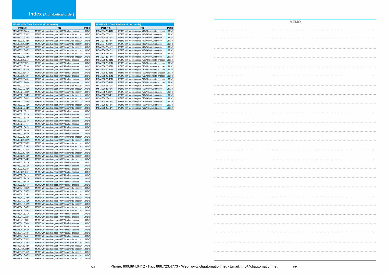
F43
MEMO
F42
Index (Alphabetical order)
MSME with Gear Reducer (Low inertia)Part No. Title Page
MSME011S44N MSME with reduction gear 100W Absolute encoder 139,145MSME012G31N MSME with reduction gear 100W Incremental encoder 139,145MSME012G32N MSME with reduction gear 100W Incremental encoder 139,145MSME012G33N MSME with reduction gear 100W Incremental encoder 139,145MSME012G34N MSME with reduction gear 100W Incremental encoder 139,145MSME012G41N MSME with reduction gear 100W Incremental encoder 139,145MSME012G42N MSME with reduction gear 100W Incremental encoder 139,145MSME012G43N MSME with reduction gear 100W Incremental encoder 139,145MSME012G44N MSME with reduction gear 100W Incremental encoder 139,145MSME012S31N MSME with reduction gear 100W Absolute encoder 139,145MSME012S32N MSME with reduction gear 100W Absolute encoder 139,145MSME012S33N MSME with reduction gear 100W Absolute encoder 139,145MSME012S34N MSME with reduction gear 100W Absolute encoder 139,145MSME012S41N MSME with reduction gear 100W Absolute encoder 139,145MSME012S42N MSME with reduction gear 100W Absolute encoder 139,145MSME012S43N MSME with reduction gear 100W Absolute encoder 139,145MSME012S44N MSME with reduction gear 100W Absolute encoder 139,145MSME021G31N MSME with reduction gear 200W Incremental encoder 139,145MSME021G32N MSME with reduction gear 200W Incremental encoder 139,145MSME021G33N MSME with reduction gear 200W Incremental encoder 139,145MSME021G34N MSME with reduction gear 200W Incremental encoder 139,145MSME021G41N MSME with reduction gear 200W Incremental encoder 139,145MSME021G42N MSME with reduction gear 200W Incremental encoder 139,145MSME021G43N MSME with reduction gear 200W Incremental encoder 139,145MSME021G44N MSME with reduction gear 200W Incremental encoder 139,145MSME021S31N MSME with reduction gear 200W Absolute encoder 139,145MSME021S32N MSME with reduction gear 200W Absolute encoder 139,145MSME021S33N MSME with reduction gear 200W Absolute encoder 139,145MSME021S34N MSME with reduction gear 200W Absolute encoder 139,145MSME021S41N MSME with reduction gear 200W Absolute encoder 139,145MSME021S42N MSME with reduction gear 200W Absolute encoder 139,145MSME021S43N MSME with reduction gear 200W Absolute encoder 139,145MSME021S44N MSME with reduction gear 200W Absolute encoder 139,145MSME022G31N MSME with reduction gear 200W Incremental encoder 139,145MSME022G32N MSME with reduction gear 200W Incremental encoder 139,145MSME022G33N MSME with reduction gear 200W Incremental encoder 139,145MSME022G34N MSME with reduction gear 200W Incremental encoder 139,145MSME022G41N MSME with reduction gear 200W Incremental encoder 139,145MSME022G42N MSME with reduction gear 200W Incremental encoder 139,145MSME022G43N MSME with reduction gear 200W Incremental encoder 139,145MSME022G44N MSME with reduction gear 200W Incremental encoder 139,145MSME022S31N MSME with reduction gear 200W Absolute encoder 139,145MSME022S32N MSME with reduction gear 200W Absolute encoder 139,145MSME022S33N MSME with reduction gear 200W Absolute encoder 139,145MSME022S34N MSME with reduction gear 200W Absolute encoder 139,145MSME022S41N MSME with reduction gear 200W Absolute encoder 139,145MSME022S42N MSME with reduction gear 200W Absolute encoder 139,145MSME022S43N MSME with reduction gear 200W Absolute encoder 139,145MSME022S44N MSME with reduction gear 200W Absolute encoder 139,145MSME041G31N MSME with reduction gear 400W Incremental encoder 139,145MSME041G32N MSME with reduction gear 400W Incremental encoder 139,145MSME041G33N MSME with reduction gear 400W Incremental encoder 139,145MSME041G34N MSME with reduction gear 400W Incremental encoder 139,145MSME041G41N MSME with reduction gear 400W Incremental encoder 139,145MSME041G42N MSME with reduction gear 400W Incremental encoder 139,145MSME041G43N MSME with reduction gear 400W Incremental encoder 139,145MSME041G44N MSME with reduction gear 400W Incremental encoder 139,145MSME041S31N MSME with reduction gear 400W Absolute encoder 139,145MSME041S32N MSME with reduction gear 400W Absolute encoder 139,145MSME041S33N MSME with reduction gear 400W Absolute encoder 139,145MSME041S34N MSME with reduction gear 400W Absolute encoder 139,145MSME041S41N MSME with reduction gear 400W Absolute encoder 139,145MSME041S42N MSME with reduction gear 400W Absolute encoder 139,145MSME041S43N MSME with reduction gear 400W Absolute encoder 139,145MSME041S44N MSME with reduction gear 400W Absolute encoder 139,145MSME042G31N MSME with reduction gear 400W Incremental encoder 139,145MSME042G32N MSME with reduction gear 400W Incremental encoder 139,145MSME042G33N MSME with reduction gear 400W Incremental encoder 139,145MSME042G34N MSME with reduction gear 400W Incremental encoder 139,145MSME042G41N MSME with reduction gear 400W Incremental encoder 139,145MSME042G42N MSME with reduction gear 400W Incremental encoder 139,145MSME042G43N MSME with reduction gear 400W Incremental encoder 139,145
MSME with Gear Reducer (Low inertia)Part No. Title Page
MSME042G44N MSME with reduction gear 400W Incremental encoder 139,145MSME042S31N MSME with reduction gear 400W Absolute encoder 139,145MSME042S32N MSME with reduction gear 400W Absolute encoder 139,145MSME042S33N MSME with reduction gear 400W Absolute encoder 139,145MSME042S34N MSME with reduction gear 400W Absolute encoder 139,145MSME042S41N MSME with reduction gear 400W Absolute encoder 139,145MSME042S42N MSME with reduction gear 400W Absolute encoder 139,145MSME042S43N MSME with reduction gear 400W Absolute encoder 139,145MSME042S44N MSME with reduction gear 400W Absolute encoder 139,145MSME082G31N MSME with reduction gear 750W Incremental encoder 139,145MSME082G32N MSME with reduction gear 750W Incremental encoder 139,145MSME082G33N MSME with reduction gear 750W Incremental encoder 139,145MSME082G34N MSME with reduction gear 750W Incremental encoder 139,145MSME082G41N MSME with reduction gear 750W Incremental encoder 139,145MSME082G42N MSME with reduction gear 750W Incremental encoder 139,145MSME082G43N MSME with reduction gear 750W Incremental encoder 139,145MSME082G44N MSME with reduction gear 750W Incremental encoder 139,145MSME082S31N MSME with reduction gear 750W Absolute encoder 139,145MSME082S32N MSME with reduction gear 750W Absolute encoder 139,145MSME082S33N MSME with reduction gear 750W Absolute encoder 139,145MSME082S34N MSME with reduction gear 750W Absolute encoder 139,145MSME082S41N MSME with reduction gear 750W Absolute encoder 139,145MSME082S42N MSME with reduction gear 750W Absolute encoder 139,145MSME082S43N MSME with reduction gear 750W Absolute encoder 139,145MSME082S44N MSME with reduction gear 750W Absolute encoder 139,145
Phone: 800.894.0412 - Fax: 888.723.4773 - Web: www.ctiautomation.net - Email: [email protected]

![MlTSUBlSHlGUIDEBOOK,JUM-606.pdf · 2019-12-31 · [Cautions on Wiring] @ DANGER 0 Switch off the external power supply before staring installation and wiring work. Failure to do so](https://img.pdfslide.net/doc/110x75/5ed3f3781188145a1e02680d/guidebookjum-606pdf-2019-12-31-cautions-on-wiring-danger-0-switch-off.jpg)