Embed Size (px)
Citation preview

genex CB ELECTRONICS
Loddonside, Lands End House, Beggars Hill Road, Charvil, Berks RG10 0UD, UKTel: +44 (0)118 9320345, Fax: +44 (0)118 9320346, www.colinbroad.com
SR/MR Serial Remotes/SynchronizersTechnical Manual
Contents
T1.00 MACRO LISTT1.01 MACRO’S 65-90T1.02 MACRO’S 91 - 120T1.03 MACRO’s 121-150T1.04 Macro’s 151-165T1.05 DAT Specific Macro’sT1.06 MR Video Streamer Specific Macro’sT1.07 ADR/Taker Specific MacrosT1.08 ID << / ID >>
T2.00 READY KEY’ST2.10 MACHINE READY BANKT2.20 SYSTEM READY BANKT2.30 SYSTEM RECORD READY TRACK ASSIGNMENTST2.31 CRASH RECORD ENABLE
T3.00 Machine ConnectionT3.01 RS422 ProtocolsT3.02 Audio MachinesT3.03 RS422 Inputs & OutputsT3.04 SR-3 Port AT3.05 Self Test
T4.00 MACHINE INTERFACE DETAILST4.01 FOSTEX D10T4.02 FOSTEX D20T4.03 FOSTEX D25T4.04 FOSTEX D30T4.05 TASCAM DA-88/SONY PCM-800T4.06 TASCAM DA-98T4.07 TASCAM DA-60T4.08 TASCAM MMR-8T4.09 SONY PCM-3324ST4.10 SONY BETACAMT4.11 SONY DVW-A500PT4.12 SONY PCM-7040T4.13 SONY PCM-7030T4.14 SONY VO-9800/VO-9850T4.15 STUDER TLS4000 Mk IT4.16 STUDER TLS4000 Mk IIT4.17 STUDER D820/D827T4.18 DAR SABRET4.19 DAR OMR-8T4.20 AKAI DR-8T4.21 AKAI DD-8T4.22 AKAI DD1500T4.23 SSL SCREENSOUNDT4.24 SSL AXIOMT4.25 AVID AUDIOVISIONT4.26 AVID NEWSCUTTERT4.27 CB BS-1/MC-1
CB Electronics SR/MR Technical Manual 25 June 2002 SR-Tech 1

T4.28 DOREMI V1T4.29 FAIRLIGHT MFX-3T4.30 Audio Kinetics ES-1.11/1.12T4.31 AuganT4.32 VPR-3 with Adrienne InterfaceT4.33 Timeline LynxT4.34 FED Audio SolutionT4.35 NAGRA TT4.36 Sony DNW-A75/A100 SX Digital Video HybridT4.37 FED V-MOD 100T4.38 PUBLISON CP+T4.39 BTS DCR 500T4.40 STUDER V-8T4.41 DivaT4.42 Otari Radar-1 revision 1.46T4.43 SSL G Series Computer (4K/5K)T4.44 Sony BVU-800 (Using timecode from an audio track)T4.45 Ampex DCT-700T4.46 Sony PCM-3402T4.47 Studer D950T4.48 Protools 5.0 - USDT4.49 Philips DCR 6024 VoodooT4.50 Midi Machine Control (MMC)T4.51a Tascam MX-2424 Midi InterfaceT4.51b Tascam MX-2424 P2 InterfaceT4.52 Tascam DA-78HRT4.53 JVC CR-600UT4.54 Panasonic AG-DS850T4.55 360 Systems TCR-4, TCR-8T4.56A Pioneer DVD-V730DT4.56B Pioneer CableT4.57 Sony MSW-M2000P Beta-Sp, Digi-Beta, Beta-SX, IMXT4.58 Accom WSD/HDT4.59 Sony DMX-R100T4.60 FEG Prima SY2T4.61 Digi-Design Protools 5.1.1T4.62 Fostex D-15T4.63 Harrison Series 12 and MPCT4.64 Fairlight VividT4.65 Leitch Video Server 420,440T4.66 AMS EncoreT4.67 Genex 8500T4.100 SSL 4K/5K Computer
T5.0 CONNECTION DIAGRAMST5.01 Power Supply ConnectorT5.02 Video Sync ConnectorT5.03 Sony 9-PIN CableT5.04 Tx-Rx Invert Sony 9 pin CableT5.05 DA-88 15-PIN CableT5.06 Audio kinetics ES1.11/1.12 CableT5.07 GP PORT CONNECTIONST5.08 S29 Remote (SR24A Only)T5.09 SR-24H (6 Port) Harrison Computer InterfaceT5.10 Sony 9 pin CABLE With Power supplyT5.11 RS232 (PC Link) CABLET5.12 RS232 (PC Link) CABLE (SR-24 ports E & F)
T6.0 Track ArmingT6.01 SR-4 Track ArmingT6.02 SR-24 Track Arming
CB Electronics SR/MR Technical Manual 25 June 2002 SR-Tech 2

T7.0 Sync optimisation7.00 Multi Machine Synchronizer Set Up7.10 Deciding between the SR/MR Synchronizer or the Machine’s built in synchroniser.7.20 Optimisation of the SR/MR Synchroniser.7.21 Sync type7.22 Park Ahead7.23 Machine Start-up Delay (Play/Advance)7.24 Pre-Roll7.25 Post Roll7.26 Delay
T8.0 Fault finding
T9.0 Video Synchroniser (VS-1) InterfaceT9.01 Video Streamer SetupT9.02 SR Wipe-length SetupT9.03 Video Streamer Interface to the SR SystemT9.04 Video STreamer Interface to the MR System
A1.0: System Setup Map
A2.0: System Record Map
CB Electronics SR/MR Technical Manual 25 June 2002 SR-Tech 3

T1.00 MACRO LIST
To change the macros Root | Unit | Generic | Menu 26: Macro protection must be set to 0=Noneas follows
MENU 26:- Macro Protection0= None 1= Keyboard 2= Factory default
For more information see section 7.26 of the user manual.
A list of all user macro’s available in table form. Macro’s prefixed by * are only available with largerEPROM’s
CB Electronics SR/MR Technical Manual 25 June 2002 SR-Tech 4

T1.01 MACRO’S 65-90
No. Description
65 BANK: The Bank key will select between blocks of record channels dependant on Root| Unit | Rec | Menu 07:- Track Arm Keys.
66 LOOP: Loop current machine between Record in and record Out
67 Assign Record keys to current Machine
68 Shifter Reset: The shifter is used as a temporary offset that is added to the currentoffset. The Shifter Reset key clears the shifter offset. Store followed by Shifter Resetwill add the contents of the shifter memory to the current offset and clear the shifter.
69 Shifter Decrement:
70 Shifter Increment:
71 Locate Start:
72 LOCAL: (Disables 9 pin Input’s when LED illuminated)
73 Mark: Grab current machine timeStore Followed by Mark = Mark Sync
Recall Followed by Mark = Find specified Mark pointShift Followed by Mark = Reset Mark Pointers
74 Instant Record: Locate -3 seconds and enter record
75 Cycle:Record Out Enable/Disable
76 Auto-Record:
77 Manual Record:
78 Review:
79 Auto-Rehearse:
80 LS Mute:
81 Auto/Manual Record:
82 Rehearse/Review:
83 All-Stop: All-Stop + All Chase Off
84 Locate (Was Ram Scrub see 168)
85 Set Generator
86 Variplay
87 Track Arm Keys: Follow Selected Mcn
88 Track Arm Keys: Follow Enabled Mcn
89 Sondor: Framing / Shift= Focus (Use with ID+ & ID- keys)
90 Erase ID: Erase DAT ID
CB Electronics SR/MR Technical Manual 25 June 2002 SR-Tech 5

T1.02 MACRO’S 91 - 120
No. Description
91
92 PNO Erase: Erase PNO
93 Pno Find: Find DAT PNO
94 ID <-: (See Section T1.08)
95 ID ->: (See Section T1.08)
96 *Alt Disp: Alternate Display
97 *Show Dif: Display Reader-Serial Difference
98 *Constant Offset:Fix Offset
99 *48KHz: Set Sampling Freq. @ 48KHz
100 *44.1: Set Sampling Frequency @ 44.1KHz
101
102
103 Out Overlap: Used to extend the record out pointStore followed by out overlap to set
104 Record Assign 1 (Use Store to set machine number)
105 Record Assign 2 (Use Store to set machine number)
106 Record Assign 3 (Use Store to set machine number)
107 Record assign 4 (Use Store to set machine number)
108
109 Ready EE: Switch All Record Ready channels between Input and Replay Monitor
110 EE: Switch current machine between Input and Replay Monitor
111 Tape Mon: Switch current machine to Replay Monitor
112 FEET: Timecode Display / Footage Display (Shift followed by Feet = Local TimeDisplay)
113 Reader: Display Timecode Reader, Recall followed by Reader will display Generator
114 Prev: Previous Loop
115 Next: Next Loop
116 Join: Join Loop
117 Insert: Insert loop
118 Generator: Display Generator, Recall followed by Generator will display Reader
119 Shuttle:
120 Jog:
CB Electronics SR/MR Technical Manual 25 June 2002 SR-Tech 6

T1.03 MACRO’S 121 - 150
No. Description
121 I-Replay:Instant Replay
122 Record Ready 1: Assignable to any machine/track, enter the machine number asSeconds, the track number as frames followed by Store followed by Key.
123 Record Ready 2: as per Record Ready 1.
124 Record Ready 3: as per Record Ready 1.
125 Record Ready 4: as per Record Ready 1.
126 Step Forward +1:- To step fwd 1 frame hit once, to move fwd 5 frames hit 5 times.
127 Step Reverse -1: To step back 1 frame hit once, to move back 5 frames hit 5 times.
128 *Loc 1: Locate Memory 1
129 *Loc 2: Locate Memory 2
130 *Loc 3: Locate Memory 3
131 Reverse Play
132 AGAIN: Locate Last Playback Start (2 Levels)
133 AGAINP: Again with Play, Shift Again: Instant Loop, Loop from Play Start to here.
134 Wind @ *2: both fwd and rvs wind commands are converted to shuttle at 2* play speed.
135 Wind @ *4:
136 Wind @ *6:
137 Eject: Eject Current Machine, Shift followed by Eject = Eject All
138 Key Lock: Locks out the following keys:-Machine Selection, Chase On/ Off, Record Machine Selection(MR only)
139 Machines MR: Show Individual Machine status on 2 Line Display
140 Cue: Locate Record In
141 *Comm Enable: Communication Enable/Disable
142 Local Time:Select LOCAL TIME/Timecode
143 Rec Enable: Record Enable On/Off
144 *Red Light: Manual Red Light Switch
145 *Preview: Sony Preview Command
146 *Review: Sony Review Command
147 *S.Auto: Sony Auto Edit Command
148 *Pre-Roll: Sony Pre-Roll Command
149 *Set TG-1: TG-1 Set Reader
150 *Post Sync: One Key Post Sync ’D’, Position Master so that the Timecode Slate isvisible, Enter the timecode number displayed, hit this key and the offset is calculated formachine ’D’, the current video position is set as Record In, and a Chase-On command is
sent to Machine ’D’
CB Electronics SR/MR Technical Manual 25 June 2002 SR-Tech 7

T1.04 Macros 151 - 165
No. Description
151 *REC IN +1: Add one minute to Record in, subtract one minute from all offsets, Locatenew record in.
152 *Red Light OFF: Disable Red Light output
153 *Red Light Auto: Auto Red light
154 *Mute: Mute Always
155 *Auto Mute Enable: When enabled, mute output except as defined by Root | Unit |Generic Menu 30: GP Output 3 (Note: after a hard reset Auto-Mute is Enabled)
156 *PARALLEL Command Enable: MR Only
157 *PARALLEL Record Command Enable: MR Only
158 *See 142
159 *Remote Enable: Serial A(E) INPUT
160 *Set Gen: Set Generator
161 *Standby:
162 *Edit Loops:
163 *Select Master: Select master (Used when programming User Macro’s)
164 Sondor Focus Forward
165 Sondor Focus Reverse
166 Instant Loop: Loop from Last Playback Start to Here
167
168 *Scrub: 7050/7040 Ram Scrub (Was Locate see 84)
169 *Sony: Sony Protocol:
170 *SX/D88: Sony SX/Tascam D88 Protocol:
171 *D827: Studer D820/D827 Protocol:
172 *TLS: Studer TLS 4000 Protocol:
173 *Lynx: Timeline Lynx/Ampex Protocol
174 *ES Bus: Audio Kinetics ES1.11 Protocol
175 *Clear Offsets: Shift= Clear All Offsets and Chase (Same as Shift Master-Chase/Offset)
176 *Field -: Previous Field Ampex Protocol
177 *Field +: Next Field Ampex Protocol
178 *Instant Lock: (Shift Chase)
179 *Make Master: (Shift Machine Key)
180 *Instant Fwd: Locate 10 Seconds ahead then Play ( As Instant Replay)
181 *Play Seg: Doremi V-1 Play Segment
182 *Select Seg: Doremi V-1 Select Segment
183 *Define Seg: Doremi V-1 Define Segment
CB Electronics SR/MR Technical Manual 25 June 2002 SR-Tech 8

Macro’s 184 - 200
184 *Record Enable: Current Machine Record Enable/Disable
185 Record Track Map: Custom 1
186 Record Track Map: Custom 2
187 Record Track Map: Machine Map 1
188 Record Track Map: Machine Map 2
189 *Sync: Constant Offset Mode On/OffShift,Sync: CMaster Chase On
190 *Cue: Locate In point
191 *Park: locate preroll before in point
192 *Insert: Video Streamer Insert On/Off (MR Only)
193
194
195
196
197
198 *Dec Offset: Decrement Offset
199 *Inc Offset: Increment Offset
200
CB Electronics SR/MR Technical Manual 25 June 2002 SR-Tech 9

T1.05 DAT Specific Macro’s
Description MacroNo.
Sony PCM-7030
FostexD25
FostexD30
Auto-ID Write 88
PNO Renumber 89 O.K. YES
Erase ID 90 O.K(Illegal)
YES
Write Specified PNO 91 Start IDonly
YES
Erase Specified PNO 92 NO
Find Specified PNO 93 O.K. YES
Previous ID 94 O.K. YES
Next ID 95 O.K. YES
T1.06 MR Video Streamer Specific Macro’s
192 All Insertions On/Off, Shift Macro = BVB Mode On/Off
193 Data Line On/Off
194 Previous Data
195 Next Data
196 Delete Current Cue, Shift Macro = Delete All Cues
197 Delete All Cues
Other Non Specific Macro’s
112 Feet: Change Insert to Feet
142 Local Time: Change Insert to Local Time
If The Record/Lock Flag is enabled on the Video Streamer then a Box will be inserted next to thetimecode insert when the system is locked, a R will indicate when the system is in Record.
CB Electronics SR/MR Technical Manual 25 June 2002 SR-Tech 10

T1.07 ADR/Taker Specific Macros
75 Record Out Enable:
76 Auto record
77 Manual Record
78 Review
79 Rehearse
81 Auto record: Shift Macro = Manual Record
82 Rehearse: Shift Macro = Review
94 Previous ID: When ADR Mode Active this becomes Previous Loop
95 Next ID: When ADR Mode is Active this becomes Next Loop
114 Previous Loop
115 Next Loop
116 Join Loop, Keep Current In- time and change Out-Time to Next Out Time
117 Insert Loop: Shift Macro: Delete Current Loop
T1.08 ID << / ID >>These are multi-purpose keys that change their function dependant on various parameters, the logicused is as follows:-
[Shift] followed by [ID <<] or [ID >>] Display current in and out points
[ID <<] or [ID >>]If Auto record/Rehearse/Man/Review active or Loop displayed then Previous/Next LoopElse-If Current machine is type DAT1 or DAT2 then :-Previous/Next IDElse-If VARI-PLAY/Slow-motion is active then:- Reduce/Increase speedElse-If Doremi V1 Previous/Next SegmentElse-If Sondor then adjust focus +/-Else Previous/Next Mark point
Not currently implemented:-Else-If MR System and Giant Display fitted then Decrease/Increase Brightness
CB Electronics SR/MR Technical Manual 25 June 2002 SR-Tech 11

T2.00 RECORD READY KEY’S
The Record Ready keys operate in three different ways as defined in Root | Unit | Record | Menu 7:Track Arm Keys
The three Settings are defined as follows:-0= System Record Ready
The Record Ready keys may access any track on any machine controlled (Maximum 4) the bankkey controls access to a maximum of 48 tracks. The number of banks is set by the setup menu.
1= Machine Record ReadyThe Record ready keys control the currently selected machine only, the bank key allows access thetracks available on the currently selected machine.
2= Record Enabled Machine ReadyThe record ready keys are assigned to the last record enabled machine selected.
T2.10 MACHINE RECORD/RECORD MACHINE READY BANKThe machine ready bank switch is used to access the all record tracks of the currently selectedmachine using Record Ready switches 1-T2.
MACHINE/RECORD MACHINE READY BANK SWITCH
Record Command Type > 1= Analog 2= 8 Track 3= 16 Track 4= 24 Track
Bank 1 A1..A4+Video
D1..D8 D1..D8 D1..D8
Bank 2 Not Available A1..A4+Video
D9..D16 D9..D16
Bank 3 Not Available Not Available A1..A4 D17..D24
Bank 4 Not Available Not Available Not Available A1..A4
T2.20 SYSTEM READY BANKThe System ready bank key is used to access all the system record ready switches using the first eightrecord ready switches as follows:-
SYSTEM READY BANK SWITCH
Bank 1 System Ready 1-8
Bank 2 System Ready 9-16
Bank 3 System Ready 17-24
Bank 4 System Ready 25-32
Bank 5 System Ready 33-40
Bank 6 System Ready 40-48
CB Electronics SR/MR Technical Manual 25 June 2002 SR-Tech 12
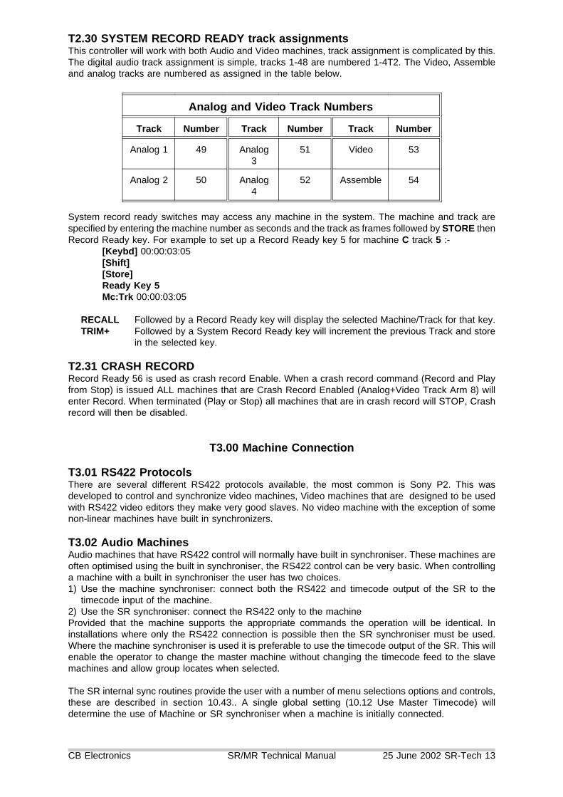
T2.30 SYSTEM RECORD READY track assignmentsThis controller will work with both Audio and Video machines, track assignment is complicated by this.The digital audio track assignment is simple, tracks 1-48 are numbered 1-4T2. The Video, Assembleand analog tracks are numbered as assigned in the table below.
Analog and Video Track Numbers
Track Number Track Number Track Number
Analog 1 49 Analog3
51 Video 53
Analog 2 50 Analog4
52 Assemble 54
System record ready switches may access any machine in the system. The machine and track arespecified by entering the machine number as seconds and the track as frames followed by STORE thenRecord Ready key. For example to set up a Record Ready key 5 for machine C track 5 :-
[Keybd] 00:00:03:05[Shift][Store]Ready Key 5Mc:Trk 00:00:03:05
RECALL Followed by a Record Ready key will display the selected Machine/Track for that key.TRIM+ Followed by a System Record Ready key will increment the previous Track and store
in the selected key.
T2.31 CRASH RECORDRecord Ready 56 is used as crash record Enable. When a crash record command (Record and Playfrom Stop) is issued ALL machines that are Crash Record Enabled (Analog+Video Track Arm 8) willenter Record. When terminated (Play or Stop) all machines that are in crash record will STOP, Crashrecord will then be disabled.
T3.00 Machine Connection
T3.01 RS422 ProtocolsThere are several different RS422 protocols available, the most common is Sony P2. This wasdeveloped to control and synchronize video machines, Video machines that are designed to be usedwith RS422 video editors they make very good slaves. No video machine with the exception of somenon-linear machines have built in synchronizers.
T3.02 Audio MachinesAudio machines that have RS422 control will normally have built in synchroniser. These machines areoften optimised using the built in synchroniser, the RS422 control can be very basic. When controllinga machine with a built in synchroniser the user has two choices.1) Use the machine synchroniser: connect both the RS422 and timecode output of the SR to the
timecode input of the machine.2) Use the SR synchroniser: connect the RS422 only to the machineProvided that the machine supports the appropriate commands the operation will be identical. Ininstallations where only the RS422 connection is possible then the SR synchroniser must be used.Where the machine synchroniser is used it is preferable to use the timecode output of the SR. This willenable the operator to change the master machine without changing the timecode feed to the slavemachines and allow group locates when selected.
The SR internal sync routines provide the user with a number of menu selections options and controls,these are described in section 10.43.. A single global setting (10.12 Use Master Timecode) willdetermine the use of Machine or SR synchroniser when a machine is initially connected.
CB Electronics SR/MR Technical Manual 25 June 2002 SR-Tech 13

T3.03 RS422 Inputs & OutputsEvery RS422 connector has both input and output connections, the Sony manual describes Controllingand Controlled devices. To simplify this we normally talk about RS422 inputs (Controlled Devices) andRS422 outputs (Controlling devices). The Controlling device (Editor, Synchroniser..) has an RS422output, the controlled device (Machine) has an RS422 input.
To complicate matters the connectors on both controlling (output) and controlled (input) devices arenearly always a female. Some RS422 connections (SSL, CB SR port A, Akai, Avid, DAR ..) can besoftware switched between outputs (controlling) and inputs (Machine emulation). With these machinescare must be taken with the connecting cable to ensure that Tx (Transmit) is connected to Rx(Receive). The options are as follows:-1) Switch the Rx and Tx connections automatically:- Akai2) Switch the Rx and Tx connections with Links:- CB SR-4/33) Provide special Machine emulation cables:- Avid4) Require a Tx-Rx Invert cable: SSL, DAR
T3.04 SR-3 Port APort A on the SR may be configured as an Input or as an Output in software. as follows:-1) Select Root | Unit | Generic | Menu 27: Serial A Type and select type 1= Input.
2) Either use a TX-Rx invert cable to connect to port A where the 4 internal links are configured as aSR-4 (Vertical to back panel), or Change the 4 internal links on Port A to be parallel to the backpanel as per the diagram at the end of this manual.
Once configured as an input the following changes are made to the unit.1) The controller connected to port A will control the currently selected master (B, C, D).2) Key [A] will become a local Switch, when the LED is illuminated this will disable control from port
A.
T3.05 Self TestTo check that port A is correctly configured as an input connect a machine to port B, configure as amaster ([Shift} followed by [B]) and connect port A to port C (Use a Tx-Rx Invert cable if required). Themachine on Port B may be then be controlled from either B or C on the SR-4. Note that when LED Ais illuminated Local will be displayed when C is selected.
CB Electronics SR/MR Technical Manual 25 June 2002 SR-Tech 14

T4.00 MACHINE INTERFACE DETAILSThese notes are included for reference, they include some machine setup details and some SR Setupdetails, if the machine is correctly identified by the SR then there should be no need to change thesetup unless the machine software has changed significantly.
T4.01 FOSTEX D-10
CHASEThe D-10 has no chase capability and must be used as a master only.
VIDEO SYNCSThe D-10 does not resolve to video syncs, it may only be used in systems with slaves thatwill chase timecode.
The D-10 is not recommended for video applications, if used as a master to a video machinethen the lock will be +/- 1 frame.
MACHINE TYPEDAT-1: Assemble record only audio + timecode, Returns A1, A2, A3 record ready at alltimes. Record ready keys are not normally required. The SR & MR remotes check that eitherA1, A2 or A3 record ready enables are active as record enables for the D10.
EDIT-ONThe D-10 ignores the Edit-On command, A Record-On command must be sent to enterRecord! Enable Record-On instead of Edit-On command in the interface setup.
TIMECODE GENERATORThe D-10 has no internal timecode generator, because of this it is recommended that greatcare should be taken when formatting DAT’s. The Timecode generator must be referenced tovideo and the D-10 must be referenced to word clock derived from the same video syncs.
DEVICE IDReturns the FOSTEX generic ID only
T4.02 FOSTEX D-20
D20
D20B
CB Electronics SR/MR Technical Manual 25 June 2002 SR-Tech 15

T4.03 FOSTEX D-25
Record Enable1) Record enables A1, A2, A3, or assemble2) Via the RS-422 it is possible to record on individual tracks, to enable on the SR/MR SetIFACE|General|Machine Type to 4= Dat2
RECORD TALLY BUGThe D-25 record tallies only appear on D1, D2 not on A1, A2, or A3.
Timer-1 BugTimer 1 position request reports timecode not timer.
Offset Command Bug1) Offset commands cancel locates
Select-EE Status BugNo Select-EE tally
Chase Command BugDoes not support Chase until locked command
THIS MACHINE WILL NOT LOCK TO PULL-UP/DOWN CODE
VTR Emulation000 FOSTEX 001 PCM-7050002 PCM-7050 003 BVU-800004 BVU-800 005 BVU-800
T4.04 FOSTEX D-30
RECORD MODES1) Play & Record: A1 & A2 & A3 individually2) Instant Start: No Record3) Confidence Record: ASSEMBLE edit only!.4) Sub ID Edit: A1, A2, & A3 individually available
RECORD COMMAND’sA1, A2 A3 only not D1 or D2
RECORD TALLIESRemote A1/A2 record enable returns both A1/A2 and D1/D2 tallyLocal A1/A2 record enable returns only D1/D2 tallyRemote D1/D2 record enable have no effectRemote or Local A3 (Timecode) record enable returns A3 tallyRemote Assemble enable returns assemble tallyLocal Assemble enable returns no tally (Insert flag Only)
TIMECODE STANDARD BUG1) ID Data does not change with standard change unless he unit is powered down and upunless new standard is the same as recorded on the tape.
SERIAL PORT STARTUPSerial port disconnection and reconnection can cause the Fostex Serial software to lock out,if this happens switch machine power off then on.
CB Electronics SR/MR Technical Manual 25 June 2002 SR-Tech 16

T4.05 TASCAM DA-88 / Sony PCM-800
VARI-PLAY/CHASENot all versions of the DA-88 software support vari-play commands. If your software does notoperate correctly then DA-88’s internal chase synchroniser must be used. To use the internalchase synchroniser the master timecode or timecode output of the SR-4 must be taken tothe timecode input of the DA-88. VARI-PLAY commands issued from play intermittentlycause the transport to stop.
TRACK ENABLE BUGEarley Software Front panel track enable switches do not update the P2 Serial port! WhenCommands on the SR remote are disabled the record tallies on the remote will not reflect thecurrent status of the machine. On Later software this is corrected!
EDIT STATUS BUGThe Edit status flag is not cleared on the RS422 port if you drop out of record on themachine, remote or due to lost lock. The Record tally operates correctly and is cleared.
UNLACED TALLY BUGThe DA-88 does not report its unlaced status when it unlaces due to timeout. To Lace theDA88 depress the stop key on the SR-4 before issuing a chase command.
LOCK TALLY BUG1 The DA-88 Lock tally is removed when in record or edit. This can cause a problem with the
Mute output when dropping out of record.2 The Lock Tally is removed if TC Generate is enabled
SY-88 SWITCH SETTINGSSwitch settings:-
S1 Rear Panel#1 video 75R termination = down#2 Must be DOWN for RS422 (Switch Power Off & ON after changing)#3 Down = Rechase#4 Down = 1 sec, Up= 2 sec#5 Timecode Output timing Up = Digital Audio, Down= Analog Audio#6 Midi TC Source#7 Must be UP for Video Resolve
S3 SY-88 Nearest edge#1 OFF Tascam ID#2 OFF Tascam ID#3 OFF Tascam ID#4 ON Digital 1-8#5 OFF Digital 1-8#6 Shuttle Speed:- ON = 8*, OFF = 100*#7 ON Track Arming enabled from 9-pin#8
Version 4Select TC display, Depress ^ and v together to enter setupuse the ^ and v keys to change a menu item, depress display to change menu.1) Chase mode:- . . . . . . . . . . . . . . . ChS. rEch2) Remote Enable:- . . . . . . . . . . . . . . rent EnA3) Device type:- . . . . . . . . . . . . . . . . d. tASCAn4) Track Arm On:- . . . . . . . . . . . . . . trK.Arn.on5) Track arm type:- . . . . . . . . . . . . . . . tn. d 1-8
PCM-800 Word Clock InputPCM-800(UC) 20001+, PCM-800(CE) 50001+
The Wordclock input is level sensitive and will not work correctly with the word clock outputsfrom the PCM-7030 or PCM-7050 details from Sony APM95-049R 22nd Dec 1995
PCM-800 SYSCON PCB change R9 from 100R to 10K and Remove R10. Then use an external75 Ohm Terminator. Or use a W/C distribution Amp!
CB Electronics SR/MR Technical Manual 25 June 2002 SR-Tech 17

T4.06 TASCAM DA98 Sys Ver 1.0, Sync Ver 1.0 Current version 1.2 for both
TRACK ARM TALLY BUG (Fixed in Sys version 1.2, Sync Ver 1.2)The response to the track-arm tally request is inaccurate and its use must be disabled:-Version 1.0 Select Root/Iface/Record/Menu 41:- Track Ready Tallies . . . . . . . . . . 3= Stat
TRACK ARMINGVersion 1.2 Track tallies are both accurate and valid.
OFFSET BUG (On Version 1.2)This machine does not accept Negative offsets (>12:00:00:00) contact teac onwww.teac.co.jp to complain.
To Setup a DA98,1) Press ESCAPE to display Select Menu Group.2) Select Menu Group 6 9Pin(Emulation) using the cursor keys, then use ENTER key to
select the menu.3) Set Tascam emulation as follows:-
Select Eml Dev using the cursor keysUse the ENTER key to enable the adjust modeSelect TASCAM using the cursor keys.Use the ENTER key to confirm the selection
4) Set the Track map as follows:-Select Trk Map using the cursor keysUse the ENTER key to enable the adjust modeSelect the display as below using the cursor keys:-
Track MappingAnaDig 1 2 3 4 5 6 7 8Trk 1 2 3 4 5 6 7 8
Use the ENTER key to confirm the selection5) Press Escape to return to Select Menu Group
6) Select Menu Group 3 McnID,Ofst/Tmod/Rmt using the cursor keys, then use the ENTERkey to select this menu.
7) Select Trk Arm using the cursor keys, then use the ENTER key to select this menu>
8) Use the cursor keys to select Remote Track Arming enable, then confirm with the ENTERkey.
9) Select Ctrl Prt using cursor keys, then use the ENTER key to select this menu:-
10) Use the cursor keys to select 9Pin, then confirm with the ENTER key.
11) To use ABS/recorded timecode select Menu Group 5, ENTER, select Tape TC,ENTER, select TC Track/ABS as required.
Locking to Word ClockMenu 5 video resolve on:- use front panel switch to enable word clock.
CB Electronics SR/MR Technical Manual 25 June 2002 SR-Tech 18

T4.07 Tascam DA-60
1) Does not like repeat locate commands, locate routine uses up o 2 seconds play into park. Ifa locate to current position is sent the machine will wind back two seconds and relocate. Mustfeed master timecode and use machine chase.
2) Track arming
Optimum SetupSuggested setup:-
Menu 41: Chase Command type . . . . . . 5=0Menu 42: Start Up Delay . . . . . . . . . . 6= FramesMenu 43: Park Offset * 5 Frms8= (To minimise play to park)Menu 44: No. of Attempts for zero error . . 4=Menu 45: Acceptable Error . . . . . . . . . . . 1=Menu 46: Locate Speed . . . . . . . . . . 4=VSLOWMenu 47: Slew Command Type . . . . 0= Vari-PlayMenu 48: Play+Lock before variplay . . 1= YesMenu 49: Chase Locate . . . . . . 0= Wind then Locate
DA-60 Mark IIUse Analog track armingChase type 5/0Reports $b4 in digital tracks 1-8 when any track is armedTrack 3 (Timecode) will only work when tracks 1&2 are disabled
T4.08 Tascam MMR-8 vERSION 3.
MMR-8 Setup1) Depress Setup key2) Depress the 0 key to select 000 Control Mode2) Depress Trim key and adjust jog wheel until the display shows Editor3) Depress the store key4) Depress the setup key to exit
Connect the SR3/4 to the Editor 9 pin port on the rear of the MMR-8
SynchronisationSoftware revision 4.2 includes the chase and set offset commands. Use chase type 0It also seems to lock using chase type 4.
Serial protocolThe On-Line key must be illuminated for a servo lock tally.
CB Electronics SR/MR Technical Manual 25 June 2002 SR-Tech 19

T4.09 SONY PCM-3324S
TIMECODEFor accurate control it is recommended that the timecode output from the machine isconnected to the SR timecode input and that this is used to update the position when valid. (Note: There is only one timecode reader per SR system, and one per box in an MR System).
TIMER MODETimer Mode must be switched to timecode
VIDEO SYNC LOCK ENABLEFor synchroniser to operate correctly Enable Timecode sync play on timecode board
CHASE COMMAND BUGThe RS422 Chase command does not work, returns undefined command
OFFSET COMMAND BUGThe RS422 Offset command inoperative, returns undefined command
POSITION REPORT BUGSome 3324S’s do not report there position correctly via the RS422 port, this causesproblems when locking up. Typically the difference between the timecode and the timereported on the RS422 port varies from 0 to 10 frames or more!If you have this problem then get a copy of the Sony Technical Memo APM95-005 from yourlocal Sony service office. After this modification has been carried out the DABK-3322 9-pininterface board must be installed in the middle slot of the right hand three slots. This isshown as slot 2 on page 2-1 of the DABK-3322 manual.
LOCK STATUS BUGThe 3324 Reports Lock even in Vari-Play, or when the Play LED is flashing.
RECORD STATUS BUGThe 3324S does not report track 1-8 record status in the normal status data
TRACK ARM/E-E BUGThe 3324 will not drop out of Auto-E-E in play only stopTracks 1-8 will drop out of Edit when edit off is sent in stop after auto e-e commandTrack arm commands upset the position reporting from the 3324
Rehearse/Auto Input bugOnce the auto input command is sent, there is no way of removing the auto input tally.
Sony SetupVari-Sync On/Off (Dip switch 4),
The optimum setting of this switch is 3324 software revision dependant! Newsoftware seems to work with Vari-Sync OFF
Advance Record OffTCGEN set to EXTERNALTimecode sync play ON (Timecode Board)Timer mode = Timecode
CB SetupChase Type 3Start up Delay 7Wait for code 9
Software version numbers1) MC software is displayed on power-up 3.022) Servo card, 3.01 + 3.02A3) DABK-3322 Option board on rear 3.02A
External Word ClockWhen running to external word clock Programable Play will not work, Root | IFace | Chase |Menu 47: Slew Commande should be changed to 0= Vari-P, 2= Prog-P, or 3= V->PPcannot be used. As the 3324 is no longer locking to the video frame edge
Internal Synchroniser Free Mode/Address ModeThe internal synchroniser may only be used in Free Mode when using external word clock. Inthis mode the synchroniser will lock and release to external wordclock.
CB Electronics SR/MR Technical Manual 25 June 2002 SR-Tech 20

T4.10 SONY BETACAM
VARIPLAYTo slave a Betacam machine variplay must be ENABLED
VARIPLAY RANGETo slave a Betacam in both forward and reverse, menu 301 Variplay Range forSynchronization on the Betacam should be set to -1.3 ~ +2.3. When shipped this menucannot be selected, The System Setup Menu Select switch (S106 on machine tested) on theSY-61A system board must be on to allow access to this menu.
T4.11 Sony DVW-A500P
Digital Betacam
LOCATEThe A500 may be set in menu to Stop or Still at the end of a locate, this must be set to Still sothat you may see the picture after a locate or when a slave.
Menu 401 "After Cue -> Still"
EEThe A500 does not respond to Full-EE ON or Full-EE OFF commands. The EE Flag in thestatus is not valid.
Machine IDThis may be set in maintenance mode to be different machines for different editors. Hold menukey down so that customise menu is enabled. Jog to the end, then hold the play key down andjog to F16 D-Type Modi and enable. Exit and re-enable the SETUP-1 Menu. use the JOG andPLAY keys at the end to access menu F-1T4.
Tracks 1..4 are Digital audio recordTrack 49 or 50 are both cueTrack 51 is timecode
T4.12 Sony 7040 2.+
7040 SetupGen Out Regen NOSync Record Enable = ON
Other settings should be the same as the 7030
The machine ID of the 7040 may be changed on S302 which is an DIL 8 switch located at therear left of the unit as follows
S302-3 S302-4 Device TypeOFF OFF 7030ON OFF 7050OFF ON 7040ON ON 7040
CB Electronics SR/MR Technical Manual 25 June 2002 SR-Tech 21
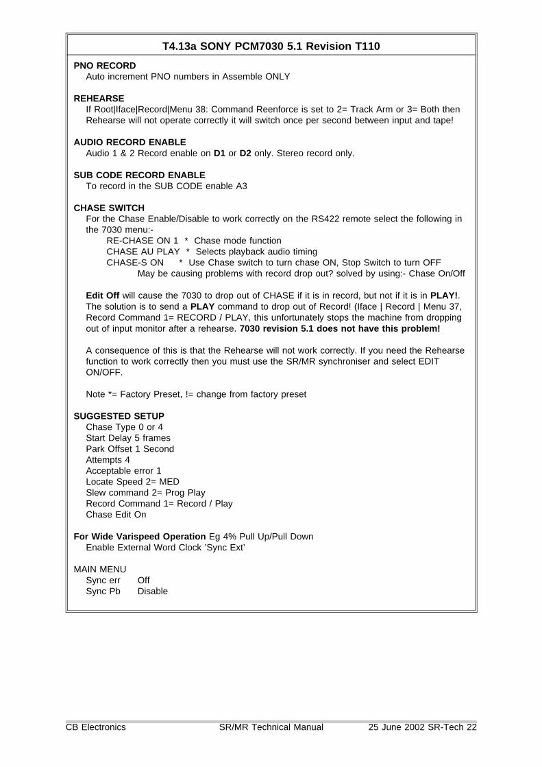
T4.13a SONY PCM7030 5.1 Revision T110
PNO RECORDAuto increment PNO numbers in Assemble ONLY
REHEARSEIf Root|Iface|Record|Menu 38: Command Reenforce is set to 2= Track Arm or 3= Both thenRehearse will not operate correctly it will switch once per second between input and tape!
AUDIO RECORD ENABLEAudio 1 & 2 Record enable on D1 or D2 only. Stereo record only.
SUB CODE RECORD ENABLETo record in the SUB CODE enable A3
CHASE SWITCHFor the Chase Enable/Disable to work correctly on the RS422 remote select the following inthe 7030 menu:-
RE-CHASE ON 1 * Chase mode functionCHASE AU PLAY * Selects playback audio timingCHASE-S ON * Use Chase switch to turn chase ON, Stop Switch to turn OFF
May be causing problems with record drop out? solved by using:- Chase On/Off
Edit Off will cause the 7030 to drop out of CHASE if it is in record, but not if it is in PLAY!.The solution is to send a PLAY command to drop out of Record! (Iface | Record | Menu 37,Record Command 1= RECORD / PLAY, this unfortunately stops the machine from droppingout of input monitor after a rehearse. 7030 revision 5.1 does not have this problem!
A consequence of this is that the Rehearse will not work correctly. If you need the Rehearsefunction to work correctly then you must use the SR/MR synchroniser and select EDITON/OFF.
Note *= Factory Preset, != change from factory preset
SUGGESTED SETUPChase Type 0 or 4Start Delay 5 framesPark Offset 1 SecondAttempts 4Acceptable error 1Locate Speed 2= MEDSlew command 2= Prog PlayRecord Command 1= Record / PlayChase Edit On
For Wide Varispeed Operation Eg 4% Pull Up/Pull DownEnable External Word Clock ’Sync Ext’
MAIN MENUSync err OffSync Pb Disable
CB Electronics SR/MR Technical Manual 25 June 2002 SR-Tech 22

T4.13b Sony PCM7030/7040/7050
Menu 42Chase Type
Menu 37 RecordCommand Type
Sony PCMMenu
Limitations
0= Cmd 0= Edit On/Off Chase-S on Will drop out of Edit when receiving anEdit Off Command
0= Cmd 1= Record/Play Chase-S on Rehearse Off will not Function
0= Cmd 0= Edit On/Off Chase-S on/off Cannot take Sony PCM out of ChaseMode
4= + 0= Edit On/Off Not Used Longer to LockMust use Video Not Wordclock
T4.14 SONY VO-9800/VO-9850
VO-9800 TRACK ENABLEAudio-1 is permanently enabled, because of this the unit will initialise with Record disabled.To layback or record on Audio-1 use the serial setup to enable record commands to themachine.
VO-9850 TRACK ENABLEThe machine must be in EDIT (MODE SELECT SWITCH) for the EDIT commands to work.
CHASETo slave this or any video machine ensure that the colour framing is turned OFF. The SRsoftware will send a COLOUR frame off command to the machine on entry to play. On exitfrom play the SR-4 will send a "Set colour Framing to Switch" command.
TIMECODEA timecode card must be fitted and the display selector must be set to TC in order for thelocates to operate correctly.
LOW BAND TAPESWhen Audio-1, Audio-2 or VITC only are used for timecode we recommend that the machineis modified to allow timecode track selection from the front panel. This allows the user toselect Audio-1, Audio-2, code-track, or an external VITC to LTC converter as the timecodesource for the internal timecode reader. This value is then updated by the tach if thetimecode is not readable and allows the machine to perform timecode locates.
CB Electronics SR/MR Technical Manual 25 June 2002 SR-Tech 23

T4.15 STUDER TLS4000 Mk I
Local Control UnitThis must be disabled in order to use the RS422 remote!
RECORD TRACK ENABLESAvailable for studer multi-track machines
The TLS Mk I programs the record enable for two channels with each command. There mustbe a time delay between each command. The commands include the monitor setting andmute status. The SR-4 will set each track between Record ready and Sync Replay, orNormal Replay dependant on the setup configuration.
Bug: Reports last serial command not actual tallies.
DEVICE TYPEWill always report as TLS Mk 1
SHUTTLE & JOGNot yet implemented
1) Hardware Switch at RearA BX
XXX
2) Middle SwitchOFF 1ON 2
3) Baud rate links at Front Right hand side: Two Links as follows1234567890.XX.....X.........X.
CB Electronics SR/MR Technical Manual 25 June 2002 SR-Tech 24

T4.16 STUDER TLS4000 Mk II
Local Control UnitThis must be disabled in order to use the RS422 remote!
CommunicationThe SR-4 will talk to one TLS4000 synchroniser only on each output port, RS422communications using the native TLS format are used.
Record The TLS Mk II programs 4 channels with each command
DEVICE TYPECurrently reports as TLS Mk 2
SHUTTLE & JOGNot yet implemented
1) LEFT HAND SWITCH1 =ON \2= OFF > 38K43= OFF /4= OFF \ EVEN PARITY, ONE STOP5= ON /6= ON \ RS4227= OFF /8= OFF
Both LED’s OFF = NO COMMSLeft OFF, Right ON = OK
T4.17 STUDER D820
SHUTTLE & JOGNot yet implemented
SETTINGSThe Internal Synchroniser must be selected (The Front Panel Lock key should operate)
RECORD TALLY BUGStrange Track Record tallies are generated even when the machine is not in record if themachine drops out of record due to loss of lock. A special routine has been written tocompensate for this. If the system locks up in stop with the record tally on then deselect themachine, and on the machine enter play, record on then off. Then reselect the machine.Alternatively turn the D820 off then on.
LOCK ERROR BUGThe D820 sometimes outputs its lock error without subtracting the offset. A Machine powercycle may cure this.
Internal SynchroniseInternal Synchroniser OnTC Lock Off
CB Electronics SR/MR Technical Manual 25 June 2002 SR-Tech 25

T4.18 DAR SABRE
CABLE: The 9 pin cable must have the Rx & Tx inverted (Section T5.02)
Reverse Play BugThe Sabre will not accept reverse play commands
Chase Command BugChase Not implemented
Record enableOnly when in stop, ignores reenforcement commands if enabled in any other mode and thenstopped.
Menu, Full VTR Emulation/Emulation TimecodeVTR Emulation must be displayed on screen
DAR Soundstation Gold
Normal Mode1) May not accept SR timecode2) Does not issue Locates3) Does not issue Record commands4) No wind speed limits to work with non-linear video
VT Emulation1) No Jog with Audio2) Does not accept reverse play command3) Front panel switched off, not possible to control both DAR and SR4) No Machine ID , Auto Setup will not work, You will have to set all the parameters as follows:-
Chase Type . . . . . . . . . . . . . . . . . . . . . 5=0Record tracks . . . . . . . . . . . . . . . . . . . . . 8
5) Make sure that Video Lock is enabled on the DAR so that the Lock tally is returned.
T4.19 DAR OMR-8
The following commands are not implemented:-
1) Vari-play, Shuttle, Jog2) Set Offset
The following tallies are not implemented:-1) Local2) Record tallies, if changed at the machine3) Response to command request track ready status (43 30 02)
CHASEChase 0=Cmd must be used, offset must be set on the machine.
CB Electronics SR/MR Technical Manual 25 June 2002 SR-Tech 26
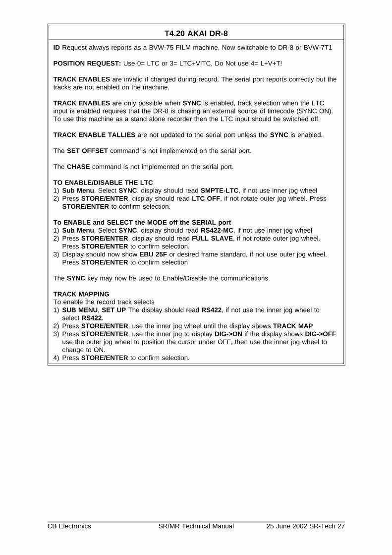
T4.20 AKAI DR-8
ID Request always reports as a BVW-75 FILM machine, Now switchable to DR-8 or BVW-7T1
POSITION REQUEST: Use 0= LTC or 3= LTC+VITC, Do Not use 4= L+V+T!
TRACK ENABLES are invalid if changed during record. The serial port reports correctly but thetracks are not enabled on the machine.
TRACK ENABLES are only possible when SYNC is enabled, track selection when the LTCinput is enabled requires that the DR-8 is chasing an external source of timecode (SYNC ON).To use this machine as a stand alone recorder then the LTC input should be switched off.
TRACK ENABLE TALLIES are not updated to the serial port unless the SYNC is enabled.
The SET OFFSET command is not implemented on the serial port.
The CHASE command is not implemented on the serial port.
TO ENABLE/DISABLE THE LTC1) Sub Menu, Select SYNC, display should read SMPTE-LTC, if not use inner jog wheel2) Press STORE/ENTER, display should read LTC OFF, if not rotate outer jog wheel. Press
STORE/ENTER to confirm selection.
To ENABLE and SELECT the MODE off the SERIAL port1) Sub Menu, Select SYNC, display should read RS422-MC, if not use inner jog wheel2) Press STORE/ENTER, display should read FULL SLAVE, if not rotate outer jog wheel.
Press STORE/ENTER to confirm selection.3) Display should now show EBU 25F or desired frame standard, if not use outer jog wheel.
Press STORE/ENTER to confirm selection
The SYNC key may now be used to Enable/Disable the communications.
TRACK MAPPINGTo enable the record track selects1) SUB MENU, SET UP The display should read RS422, if not use the inner jog wheel to
select RS422.2) Press STORE/ENTER, use the inner jog wheel until the display shows TRACK MAP3) Press STORE/ENTER, use the inner jog to display DIG->ON if the display shows DIG->OFF
use the outer jog wheel to position the cursor under OFF, then use the inner jog wheel tochange to ON.
4) Press STORE/ENTER to confirm selection.
CB Electronics SR/MR Technical Manual 25 June 2002 SR-Tech 27
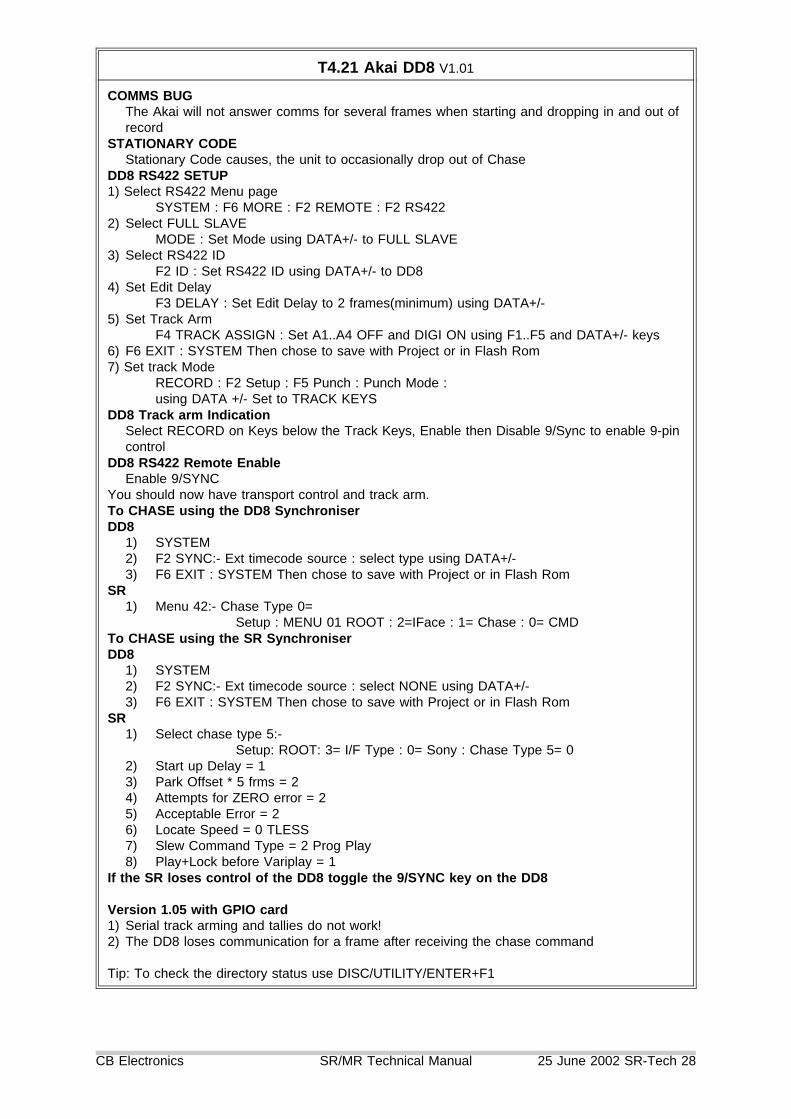
T4.21 Akai DD8 V1.01
COMMS BUGThe Akai will not answer comms for several frames when starting and dropping in and out ofrecord
STATIONARY CODEStationary Code causes, the unit to occasionally drop out of Chase
DD8 RS422 SETUP1) Select RS422 Menu page
SYSTEM : F6 MORE : F2 REMOTE : F2 RS4222) Select FULL SLAVE
MODE : Set Mode using DATA+/- to FULL SLAVE3) Select RS422 ID
F2 ID : Set RS422 ID using DATA+/- to DD84) Set Edit Delay
F3 DELAY : Set Edit Delay to 2 frames(minimum) using DATA+/-5) Set Track Arm
F4 TRACK ASSIGN : Set A1..A4 OFF and DIGI ON using F1..F5 and DATA+/- keys6) F6 EXIT : SYSTEM Then chose to save with Project or in Flash Rom7) Set track Mode
RECORD : F2 Setup : F5 Punch : Punch Mode :using DATA +/- Set to TRACK KEYS
DD8 Track arm IndicationSelect RECORD on Keys below the Track Keys, Enable then Disable 9/Sync to enable 9-pincontrol
DD8 RS422 Remote EnableEnable 9/SYNC
You should now have transport control and track arm.To CHASE using the DD8 SynchroniserDD8
1) SYSTEM2) F2 SYNC:- Ext timecode source : select type using DATA+/-3) F6 EXIT : SYSTEM Then chose to save with Project or in Flash Rom
SR1) Menu 42:- Chase Type 0=
Setup : MENU 01 ROOT : 2=IFace : 1= Chase : 0= CMDTo CHASE using the SR SynchroniserDD8
1) SYSTEM2) F2 SYNC:- Ext timecode source : select NONE using DATA+/-3) F6 EXIT : SYSTEM Then chose to save with Project or in Flash Rom
SR1) Select chase type 5:-
Setup: ROOT: 3= I/F Type : 0= Sony : Chase Type 5= 02) Start up Delay = 13) Park Offset * 5 frms = 24) Attempts for ZERO error = 25) Acceptable Error = 26) Locate Speed = 0 TLESS7) Slew Command Type = 2 Prog Play8) Play+Lock before Variplay = 1
If the SR loses control of the DD8 toggle the 9/SYNC key on the DD8
Version 1.05 with GPIO card1) Serial track arming and tallies do not work!2) The DD8 loses communication for a frame after receiving the chase command
Tip: To check the directory status use DISC/UTILITY/ENTER+F1
CB Electronics SR/MR Technical Manual 25 June 2002 SR-Tech 28

T4.22 AKAI DD1500 (Version 2.00 a/a)
To Enable the VTR CONTROL connector as a INPUT use the following key sequence:-SHIFT + EXT M/C
This displays the RS422 Machine Control Setup^ + v
Select the RS422 ModeDATA ENTRY/NUDGE +
Until FULL SLAVE is displayed^ or v
Select the RS422 IDDATA ENTRY/NUDGE +
Until DD1500 is displayedF1 TRACK ASSIGN
To access the RS422 TRACK ASSIGNMENT Menu< or > Select D1-16^ or v Select D1-16 ON to enable remote track enables
To enable external control of the track selects use the EXT M/C switch, external control isenabled when the LED is illuminated.
ID Request always reports as a BVW-75 FILM machine, Now switchable to DD-1500 or BVW-75
POSITION REQUEST: Use 0= LTC or 3= LTC+VITC, Do Not use 4= L+V+T!
CHASE BUGThe DD1500 will accept the RS422 CHASE command but unfortunately it does not exit whena STOP command is sent. This means that there is no way of exiting chase except by usingthe EXT.TIME switch on the DD1500. When the Chase (EXT.TIME) is enabled via theRS422 the DD1500 behaves differently in that when the external code stops or changesdirection the DD1500 stops chasing.
RECORD BUGIf you use a RECORD ABORT (SHIFT RECORD) on the DL1500, the next time you enablea track via the 9 pin remote the system will enter RECORD!!!!.
TRACK ARM BUGWhen in play the DD1500 will only accept the first track arm command. All subsequent trackarming commands are ignored until you STOP the DD1500.
T4.23 SSL SCREENSOUND
1) ’SETUP’ ’SERIAL’ Enable Sony Slave STD Motion Record2) ’NETWORK’ ’MACHINES’ OFF SIO Linked as controller3) Use RX/TX invert cable
CB Electronics SR/MR Technical Manual 25 June 2002 SR-Tech 29
T4.24 SSL AXIOM
The Axiom serial interfaces have four different modes of operation as follows:-1) Grey Master
All four serial ports may be grey masters, The Axiom acts as master and synchronises theattached machine to the Axiom Timeline. A grey master is always slaved to the Axiomtimeline. This mode suits fast responsive machines. A stop command from play, reverse playor wind is translated to a ’LOCATE TO HERE’ command, when slow (film) machines receivethis command they slow to a stop, reverse direction and locate to ’HERE’.
2) Green MasterOnly one port may be either a Sony Slave, Green Master or Red Master. The Axiom acts asmaster in play, but the Axiom timeline follows the Green Master position in wind. A GreenMaster is slaved to the Axiom timeline in play but acts as master to the Axiom timeline inwind. A stop from wind waits until the machine is stopped, then the timeline and all machineslocate to this position. Stop commands from play or reverse play are still translated to’LOCATE TO HERE’
3) Red MasterOnly one port may be either a Sony Slave, Green Master or Red Master. The Axiomcommands the machine, the Axiom timeline follows the Red Master machine position in allmodes. Stop from play or reverse play are still translated to ’LOCATE TO HERE’
The optimum serial setup for both Grey Master and Red Master is as follows:-Fixed adaptive lockup = 12 in PAL and 14 in NTSC
RECORD* The Axiom record switch acts as a RECORD MODE, this may be enabled at any time, Every
time a command is issued a EDIT OFF command followed by an EDIT-PRESET command issent.
* If the controlled device is in PLAY and the RECORD MODE is enabled then provided that atleast one channel is armed a series of EDIT ON commands will be sent until the device is inrecord.
* If the controlled device is put into record by another remote then the AXIOM willautomatically take it out of record if the AXIOM is not in RECORD MODE.
* If the controlled device is taken out of record by another remote then the AXIOM willautomatically put it into record if the RECORD MODE is enabled.
* The Edit On commands will start as soon as a play tally is present and will not wait for a locktally or even lock with the Axiom
PLAYThe Play tally will stop flashing when the master is in frame lock with the Axiom, the Axiomwill not wait for a Servo Lock tally.
4) Sony SlaveThe Axiom timeline is controlled by an external controller only one port may be either a SonySlave, Green Master or Red Master. The Axiom timeline is controlled in the same way asany machine by selecting Sony Slave mode. The optimum setup for controlling the Axiomfrom a CB product is as follows:-
1) LOCATE ONLY, Non linear audio a locate is always faster than Wind.2) Chase type ’5’3) Locate speed: Very Fast (Locate 0)4) Record Ready Off, the Sony command "EDIT PRESET SENSE" causes the AXIOMto lock out, to avoid this Edit Preset and Edit preset Sense commands must be turnedoff.
The lock after reverse play or reverse wind is slower than the lock after play or forward wind.The Axiom appears to take longer to start moving after reversing.
Note: The 9 pin cable must have the Rx & Tx inverted (See Section T5.02)Note 1:
In all modes the Axiom timeline is either master or follows the Sony Slave, Red Master orGreen master machine. The remaining three Grey master machines are slaved to the Axiomtimeline and will therefore follow in all modes.
CB Electronics SR/MR Technical Manual 25 June 2002 SR-Tech 30

T4.25a AVID Audiovision
The SR-3 may be used as a multi-machine controller with the Avid, by using the timecodereader the Avid may also be slaved to an external source of timecode.
1) AVID Cables:-The Avid machine control cable (Male ’D’) will work correctly with SR-4 only in Port-A if theLinks are Horizontal (SR-3) position). This cable may be used in ALL modes.
The Avid Emulation cable (Female ’D’) will work correctly with the SR-4 when connected toany port, If connected to port A then the links must be vertical (SR-4). This cable will onlywork correctly in machine emulation mode.
2) Ensure that all parts of the system are locked to video syncs, (Avid, Micro-Lynx, CB MC-1 ifused, SR-3)
3) Connect the Avid super clock input to a suitable source of 256 * Word Clock for example theDigi-Design Video Slave Driver or the Rosendahl WIF.
If the Micro-Lynx is used then the clock rate must be manually as follows:-1) SETUP : 2) ACG3) Use + or - keys to select correct frequency4) SETUP The following preferences may help: Park Ahead On
AVID Transport Control Modes:-LOCAL
No Interaction, The Avid Timecode output may be used as a master to the system,connect to SR/MR timecode input and select READER as Master.
AVID as MASTER to SR-3MASTER
The SR-3 master machine will be controlled by the Avid. In play the Avid will lock to theSR-3 Master machine.
SLAVEThe Avid will follow the SR-3 master machine.
In this mode the SR-3 should be set as followsMenu 27 Serial A type . . . . . . . . . . . . . Input
The A key will act as a Local/Remote switch for the systemUse Shift followed by B, C, D to select the Master
CB Electronics SR/MR Technical Manual 25 June 2002 SR-Tech 31

4.25b AVID as SLAVE to SR-3/4REMOTE
Used in the Deck emulation mode. The SR-3/SR-4 can control the Audiovision. TheAudiovision sends a NTSC VO9850 ident unless changed using set devicetypedatacommands as below. When using the Avid in Local, positional information on theemulation port is only updated in stop!
Notes on PCI BUS Machine1) Track arming only active when in stop
Setting the Avid ID number, the SR-4 will configure correctly if you select the 3324 id as follows,use getprop instead of set to check current settings:-Windows
Console
Setting a PAL IDset devicetypedata1 D1set devicetypedata2 A8
Setting a NTSC IDset devicetypedata1 D0set devicetypedata2 A8
Park ahead used by remote modeset slavedelay 80set parkframes 85set parkahead trueset VTRtriggerdelay 1.0 (Was 2.0)
BUG: Avid reports that the Video is always record armed
T4.26 AVID News Cutter
1) This is a DVW digital video workstation, designed to work as a stand alone system, it doesnot work with any other equipment. Although it can control an external machine for play in itcannot synchronise to an external RS422 or timecode.
2) There is no video emulation mode.
3) There is no timecode output.
4) There is no possibility of putting an external video machine into record.
The only way of getting program out of the system is to put the AVID into play and putting avideo machine into CRASH RECORD using the internal timecode generator as the timecodesource.
CB Electronics SR/MR Technical Manual 25 June 2002 SR-Tech 32

T4.27 CB BS-1/MC-1
TRACK ARMING (Available on MC-1 Only)A1..A4, Video -> Port BD1..D16, MC-1 Parallel track arm outputs 1..16
CHASE SETUPChase Type . . . . . . . . . . . . . . . . . . . . . . . 5= 0Start up delay . . . . . . . . . . . . . . 4= (Dependant on PACCN)Park Offset * 5 Frms . . . . . . . . . . . . . . . . . . 0=Acceptable Error . . . . . . . . . . . . . . . . . . . 1= FrmsLocate Speed . . . . . . . . . . . . 2= MED (Dependant on ACCN)Slew Command Type . . . . . . . . . . . . . 1= Vari-PlayWait for Code to Stabilise . . . . . . . . . . . . . . 4=Chase Locate . . . . . . . . . . . . . . . . . . 1= Locate Only
Serial Position Request . . . 1= Start of frame (Old MC-1 Software)
T4.28 Doremi V1 Version 1.99z
1) Must have correct Video reference input selected to report Servo Lock
2) Offset Cmd Bug:- A Sony Offset command sets the timecode output value.
3) Ensure that Menu 03 is not selected to "Chase Serial TC", in this mode the RS422 port is anOutput.
4) Setting the V-1 IDDepress OPTION & MENU togetherSelect the Option Menu 19 "Emulate" using the ^ & v keysUse the -- and ++ keys to select V1 emulationExit using the Menu key.
5) Use Option Menu 04 "Save Yes" to save any new defaults if necessary.
The MR/SR provides 6 commands that enable the user to accessthe V-1 Segment commands:-
note: only available when the SR-4 displays Doremi as the machine type (see 4 above).
1) Select Segment . . . . [Macro 181] or [Recall] followed by [ID >]Enter the segment number followed by [Select Segment] to locate the start of the segmentThis sets Doremi Option Menu 8!
2) Play Segment from Start . . . . . . . . [Macro 182]This command will only operate if within the selected segment (Goto Segment) or thesegment mode is off.
3) Define Segment . . . . . [Macro 183] or [Store] followed by [ID >]Define the In and Out points on the SR then enter the desired Segment number followed bythe Define Segment command.
4) Select Next Segment . . . . . . . . . . . . . . [ID >]eg, 4->5, 5->6, 6->7....255->256
5) Select Previous Segment . . . . . . . . . . [ID <]eg. 7->6, 6->5, 5->4...1->0
6) Clear Segment Mode . . [Clear] followed by 1) Goto SegmentThis will Locate the start of the Recording
The User display will show the Segment number as a PNO Number. Tape End will be displayedif at start or end of segment.
CB Electronics SR/MR Technical Manual 25 June 2002 SR-Tech 33

T4.29 Fairlight MFX-3
BUGS1) Reports timecode standard as 24 FPS
Select Root | iface | General | Menu 57: Timecode Standard 1= Use System
2) Does not accept CHASE or SET OFFSET commands
Chase SetupChase Type = 5= -+ Current MFX softwareChase type = 4= + Older MFX SoftwarePark offset = 2 10 framesStart Delay = 4Slew Command Type 0=Variplay (1=Shuttle on very old software)
T4.30 Audio Kinetics ES-1.11/1.12
The SR-4 cannot improve the basic operation of the ES 1.11, It is essential to read the AKoperation manual and parameter setup notes in order to optimise the AK 1.11.
a) Only one ES 1.11 may be connected to each serial port on the SR-4
b) Interface CableSR-4 ES 1.11
2 43 14 87 38 2
c) ES 1.11 Setup:-1) Disable BUS2) Set timeline reference as video: MENU SYSTEM MASTR Mas A3) Set ES BUS address as 001: MENU SYSTEM ESbus4) Set Mode to External: MODE mode<-Ext5) Select user preferences as required, Play to park on/off, Record enable....6) It may ne necssary to set MACH|PROG| 1014 (NoWild) to $FF
7) Enable Bus
d) SR4 Setup1) Select Serial port A,B,C, or D2) Select serial protocol "Setup" Root Menu, "2"= IFACE, "3"= Type "5"= AK
Bugsa) The ES 1.11 will only report difference when in play modeb) Offset commands cause the ES 1.11 display to flash
Emulation ModeThe AK1.11 may also be used in emulation modeIn Emulation mode the Local Setup menu LOCK should be set to Auto or Phase
1) Chase type 4
CB Electronics SR/MR Technical Manual 25 June 2002 SR-Tech 34

T4.30 Audio Kinetics ES-1.11/1.12 DEBUG MODE
A debug display is available as follows:-
1) LOCAL | Option | Parameter Protrction = Off2) MACH | PROG | Parameter 1040 (testit) set to 533) LOAD4) The debug display is enabled using the Mode Key and is changed using the Menu Key
System Position System Speed DifferenceMachine Position Machine Speed VLTr25 TLSVC Last Cmd
System Position: t= timeline, c=chase, r= real MasterMachine Position: l= ltc, t= tachVLTr25: V= VITC L=LTC T=Tach r=Record Enable 25= StandardTLSVC: T= Timeline, L= Lock Active, S= Goto Active,
V= Fast Slew v=Slow Slew l= Servo Released p= vari playC= Chase
The Menu key selects an alternative Display for the top lineTMS TMP 0f 06ts 10000000
TMS 41= Stop, 42= Variplay, 43= Play, 4c = Record, 61= FWD, 62= RWDTMP 18= Chase, 44= Step(jog), 46= Shuttle, 4e= Search(Goto), 51= Lock, 53= LPRS, 5a=
Calibrate3rd digit 0= Trying, 1= Successful, 3= Failed
Logical machine commands:00 Null 10 Lifter Normal01 Play 11 Varispeed On02 Stop 12 Varispeed Off03 Crawl Stop 13 Pause04 Record 14 Edit05 Unrecord 15 Servo06 Crawl Rvs 16 Rec Preset07 Crawl fwd 17 Locate08 Rvs Play 18 Step +09 FFWD 19 Step -0a FRVS 1a Un-Rehearse0b Toggle Mode 1b Sync Play0c Rehearse 1c Init0d Lace 1d Rehearse mode Toggle0e Unlace0f Lifter Defeat
CB Electronics SR/MR Technical Manual 25 June 2002 SR-Tech 35

T4.31 AUGAN 2.96/77S
Working with AES/WORDCLOCKBy supplying resolved Video syncs and Wordclock the Augan may be operated in RS422 deviceremote provided that it is switches to Gen-Lock Mode.1) Switch first to AES input and then to Video clock, the display should then indicate GL underthe sample rate.2) Check Parameter 40 (Digital Audio Sync Source),
On the Sync Page1) F5 sync options: F6 External clock: Sync ON, this selects video reference to the timeline.2) F1 Mode: device (This also inverts the inputs so that no TX-RX Invert cable is required)4) F2 VI Type: V1
The SYNC key is a remote enable switch (The Local/Remote Tally is not implemented by theAugan)
AUGAN OFFSET BUGOlder Software
When an internal offset is set on the Augan the RS422 position in Stop will be different fromthe position in Play. To cure reset the offset to zero. (Now corrected)
Current Software (OS2.96/71S..)If an internal offset is set, the position displayed on the SR/MR and on the Augan will bedifferent. The offset is used to calculate the Augan displayed position, the offset is not usedon the serial port.
1) Audio output in Jog and VariplayThe audio will be muted if a speed of more than +5% is requested ($4A), when in forwardthe audio will be un-muted when the speed is returned to play speed, In reverse once mutedthe audio is never un-muted, also the jog/varispeed is not correct in this mode.
CHASE SETUPChase Type . . . . . . . . . . . . . . . . . . . . . . . . 5=Start up delay . . . . . . . . . . . . . . . . . . . . . . . 5=Park Offset * 5 Frms . . . . . . . . . . . . . . . . . . 0=Play before variplay . . . . . . . . . . . . . . . . . . 0=Acceptable Error . . . . . . . . . . . . . . . . . . . 1= FrmsLocate Speed . . . . . . . . . . . . . . . . . . . . 0= TLESSSlew Command Type . . . . . . . . . . . . . 1= Shuttle !!Wait for Code to Stabilise . . . . . . . . . . . . . . 2=Chase Locate . . . . . . . . . . . . . . . . . . 1= Locate OnlyMax slew speed . . . . . . . . . . . . . . . . . . . . . 6
CB Electronics SR/MR Technical Manual 25 June 2002 SR-Tech 36

T4.32 VPR-3 Version 7.3 PAL with Adrienne Interface (BVH-2K)
Suggested setup
Chase Type . . . . . . . . . . . . . . . . . . . . . . . 5= 0Start up delay . . . . . . . . . . . . . . 7= (Dependant on PACCN)Park Offset * 5 Frms . . . . . . . . . . . . . . . . . . 5=Attempts for ZERO Error . . . . . . . . . . . . . 2= TrysAcceptable Error . . . . . . . . . . . . . . . . . . . 1= FrmsLocate Speed . . . . . . . . . . . . 2= MED (Dependant on ACCN)Slew Command Type . . . . . . . . . . . . . 2= Vari-PlayWait for Code to Stabilise . . . . . . . . . . . . . . 4=Chase Locate . . . . . . . . . . . . . . . . . . 1= Locate OnlySync Correction . . . . . . . . . . . . . . . . . . 5= NONE
T4.33 TimeLine Lynx
TimecodeTo use as a MASTER it is recommended that the machine timecode output is connected to theSR/MR timecode input. When using used as a Slave there is no problem. (Note: There is onlyone timecode input per SR system and one per box in a MR system.)
Lynx SetupTo enter the Lynx I setup menu hold the SET UP key depressed for approx 6 seconds, repeatto leave the setup menu.
To enter the Lynx II setup menu hold the Blue key on the left depressed and depress the [SETUP] key, repeat to leave the setup menu.
The MENU key is used to change the menu section, the FORW and BACK are used to selectthe item to be changed. The v, ^ and CLR keys are used to adjust the selected item.
Select the following:-Editor 0Address 1
Lynx Local/RemoteThe Tran Mode switch on the Lynx is used as a local-remote switch.
SR/MR Lynx Protocol SelectSelect the correct protocol on the SR/MR:
Root | Root | 2= Iface| 3= Type | Menu 63: Select protocol 4= Lynx
If 4= Lynx does not appear on the select protocol menu then this protocol is not fitted to yoursystem, contact your agent or CB Electronics to purchase the protocol upgrade.
Subframe OffsetsTo set sub-frame offsets, enter the required sub frame offset followed by Shift followed byStore, Followed by Chase/Offset, use Recall followed by Shift followed by Chase/Offset tosee the current sub-frame offset.
CB Electronics SR/MR Technical Manual 25 June 2002 SR-Tech 37

T4.34 FED Audio Solution II
This 4 track optical disc recorder can emulate a BVW40. The Sony P2 control input is on COM2and requires a special cable. A1..A4 are used as the track enables.
COM2 is RS232, for long cable runs a RS422 to RS232 should be used, positioned next to theAudio Solution.
Cable details without RS422 to RS232 converterSR-4 SR-4 FED COM-2Tx Data - 2 3Rx Data - 8 2Ground 4 5
T4.35 Nagra T
The connection to the Nagra T is made via the Nagra RS422 Remote Control interface TA-RSAWe have tested the unit with software version ???? fitted to the TA-RSA interface.
RS422 Connection to Centre Connector- Remote C
The Nagra ID can be set to Nagra T using the Status Key to select the Menu, The + and - keysto step through the menu and the Mod key to change the parameter. Select T-Audio
Menu 44 Startup Delay . . . . . . . . . . . . . . . 2=Menu 45 Park Offset * 5 frms . . . . . . . . . . . 5=Track Arming = A1 and A2
BUG The Nagra Lock tally is only present in Insert Mode?When switched to Insert Mode the Replay Head changes, Tracks should be enabled in stopto avoid losing lock.
T4.36 Sony DNW-A75/A100 SX Digital Video Hybrid
These machine use two different protocols one for the Tape and one for the Disk.1) Program a key to Macro 163 or use Menu 63 (Root/Iface/Type) to enable/disable thespecial protocol.
Bugs1) In Disk mode the machine will not accept variplay commands greater than +/- 1* play speed.
CB Electronics SR/MR Technical Manual 25 June 2002 SR-Tech 38
T4.37 FED V-MOD 100
SR-4 SETUPWhen selected to 422DEV in the MASTER menu the V-Mod will answer with a BVW-40 ID, tochange this select Odectics as described bellow. If this is not possible the following changesshould be made to the standard BVW-40 setup:-
IFACE-CHASEMenu 43 Chase command type . . . . . . . . . 5= 0Menu 48 Locate Speed . . . . . . . . . . . . 0= TapelessIFACE-GENERALMenu 56 Pause/Stop Command . . . . . . . 1= Stop
RECORDThe V-Mod will only accept crash record commands
TIMECODEIf the V-MOD does not have a timecode reader it will not record timecode with video. The bestway to set timecode on the V-MOD is to record a video with burnt in timecode or with a slatemark. The V-MOD may then be set to this timecode after the video is recorded.
To record with serial timecode, select 422CON in the MASTER menu, connect to the playbackmachine via RS422. Then depress Record ([REC] and [>]) on the V-Mod, The V-Mod will startthe playback machine and record audio, video and timecode.
BUG Timecode StandardWhen set to Odetics protocol the V-Mod reports an IDENT of D8 01 this indicates that it isan NTSC machine with SMPTE 30 timecode. When set to RS422 protocol the V-Mod reportsan Ident of 11 21 (BVW-40 PAL)
V-MOD SETUPTo Enter Setup1) Depress LOCK & REC simultaneously
Enable the RS-422 on the V-MOD from Setup2) Use the < and > to select the MASTER menu3) Depress the Enter(LOCK) key to select the master menu4) Use the + and - to select MASTER: Odectics (This sets the ID as V-Mod instead of BVW-40)5) Depress the Enter(LOCK) key to return to MASTER menu
To Select External Video Sync from Setup2) Use the < and > to select the VIDEO menu3) Depress the Enter(LOCK) key to select the video menu2) Use the < and > to select the VIDEO SYNC menu4) Use the + and - to select VIDEO SYNC:COMP5) Depress the Enter(LOCK) key to return to MASTER menu
To Preset the Timecode Number from Setup2) Use the < and > to select the Timecode menu3) Depress the Enter(LOCK) key to select the master menu4) Use the < and > to select the Timecode digit to change4) Use the + and - to select change the digit5) Depress the Enter(LOCK) key to return to MASTER menu
CB Electronics SR/MR Technical Manual 25 June 2002 SR-Tech 39

T4.38 Publison CP+
1) This DAW has no emulation mode and can only be used as a master to the SR-32) The 9 pin connections are non-standard
Publison SR-3Female Male1 22 73 34 85 46-97-8
T4.39 BTS DCR 500
This machine has two analog and four digital tracks, the digital tracks may be accessed asnormal (D1..D4), A1 and A2 will access D1 and D2
There are no tallies from digital tracks 3 and 4!
T4.40 STUDER V-8 Software 2.0 10/30/98
1) Depress ’UTILITY’ repeatedly until "2 ONLINE SOURCE:" is displayed.2) select using ^ or v until "2 ONLINE SOURCE: RS-422"3) Depress ’UTILITY’ and using ^ or v select "3 RS-422 Track Arm: On"4) Depress ’UTILITY’ and using ^ or v select "4 RS-422 Mapping: 1-2"5) Enable the ’ONLINE’ key
Record Tally BugNo Record tallies! select record tallies NV on SR-4
IdentSame Ident as BVH-2180 ($111C), this is good for us or we can supply an unused ident, Isuggest for use with OLD Editors you allow the user to switch between two idents, oneunique and one BVU950 or similar.
Comms bugThe RS422 port loses communication when ONLINE is off.
Offset BugThe V-8 accept’s a chase command but does not accept the Sony SET OFFSET command.
The V-8 will accept a Chase command or may be controlled by the SR-4 synchroniser, to usewith offsets the SR-4 synchroniser must be used with the current V-8 software.
Multi-machine Record EnableThe V-8 will only record as an 8 track on the current software (2.3).
Note; The V-8 will report record inhibit if the first tape is record inhibited.
Typical Internal sync settings43 Chase type 3=44 Start up delay 9=45 Park offset * 5 frames 5=
CB Electronics SR/MR Technical Manual 25 June 2002 SR-Tech 40

T4.41 Diva
ConnectionsDiva SR-41 72 311 212 86,7 4
Emulates a BVW60 NTSC only, set to use System Standard with SR/MR systemsCurrent Problems1) No Status Replys!2) Locates not frame accurate in PAL (Frame accurate in SMPTE)3) Does not accept Shuttle Commands4) All commands other than STOP or JOG ignored when in PLAY
T4.42 Otari Radar-1 revision 1.46
Record Tally BUGThe Record tallies are offset by 8 tracks ie. Track 1 reports as track 9 etc.
Record/Edit OnUse Record and Play instead of EditOn and EditOff this will enable additional tracks to bedropped in and out of record.
Track ArmingUnlike a Video machines tracks that have not previously been in record may be armed whistthe machine is in record and then may be dropped into record using a RECORD (Not EditOn) command. Tracks that have previously been in record will go back into recordimmediately when record armed.
Timecode Standard BugThe Radar does not report the current timecode standard correctly, it will always report atimecode standard of 30 NON DROP, it never reports EBU or Drop
Machine IDAuto setup not possible because there is no unique machine ID
This machine reports as a BVU950 and should be set up as follows:-
Menu Function34 Record tracks 4=2435 Analog & Video 0=disable38 Command Reenforce 2= Record (Until bug fixed)41 Record tallies 4= NV (Not Valid)43 Chase command type = 544 Start up delay =245 Park Offset = 2 (10 Frames)48 Locate speed = 0 (Tapeless)50 Wait for Stable code = 2 (4 frames)54 Machine type = 2 (ATR)
CB Electronics SR/MR Technical Manual 25 June 2002 SR-Tech 41

T4.43a SSL G Series Computer (4K/5K)
1) Connections1) Connect S29 on RM-6 Hub to ’Multitrack’ under patch on SSL Console (25 ’D’ Male -
25 ’D’ Female).2) Connect Timecode out from RM-6 Hub to Master Timecode input on SSL (S113).3) Connect S88 26 way ribbon cable (Maximum Length 2 meters) between SSL computer
’78’ Card Port 2 and RM-6 Hub
2) SSL Setup1) Type SSL Execute, the keyboard prompt should disappear, type the access code
BERNOULLI, this will not be displayed but the keyboard prompt should re-appear2) Type Setup Execute and "Do you want to see more" should be displayed3) Type # and set the following
Synchroniser type : 3Master Transport Selector : YES
4) End End5) Setup Execute6) SSL Display’s "Do you want to see more?" type "Y" to enter Engineer menu page.7) S for Session and set "Using VITC" to YES this will enable the SSL to read stationary
timecode.8) End, End9) SSL Display’s "Do you want to see more?" type "M" to enter Maintenance menu page.10) Type "T" to select tape machine.11) Select a spare tape machine position and type "Delete", answer Y12) Type in name (EG. SR-24 25FPS) followed by "Execute" and enter details as follows:-
The Tach and Direction parameters will be constant as follows:-Forward direction sense (L/H) : HIGHMultiple Play speeds : NOPulses/Second at std speed:
25 fps EBU timecode, 5 pulses per second30 fps SMPTE timecode, 6 pulses per second
Target Window : 0.0Orop Out Command Type : 1Drop In Command Type : 1Time for Startup : 1.20Time to be sure tape stopped : 1.10
The other auto-locate parameters will depend on the machine to be controlled13) End14) Type the "SYNC" key to enter Sync Menu Page15) Type the "Setup" key to enter machine setup page and enter your machine name and
select the Menu No.16) End17) Type I to select the interface menu
Z8 interface No. : 218) End19) Type the "SYNC" key to select the synchroniser options menu and set
Maximum number of masters : 5Offsets may be read from synchronizer : YESSingle Machine Mode : NOTimecode Generation : YES/NO Dependant on Machine
20) End End
CB Electronics SR/MR Technical Manual 25 June 2002 SR-Tech 42

T4.43b SSL G Series Computer (4K/5K)
3) SSL Display1) Use the Large/Small key, or use sync execute to view the machine page2) The Down cursor key switches between Position & Time to Sync3) The Left or Right Cursor keys switch between Mark & Offset
4) SSL Commands1) AM{Execute} Sets Port-A as the Master2) SYNC ON Enable synchroniser3) Offsets:- use A at 00:00:00:00, B at 01:00:00:004) Locate C goto 00:00:00:00 Execute5) ABC Setup Execute :- Toggle machine selection machines ABC6) Sub frame offsets :- B* 00 Execute7) Request Subframe offset :- B*? Execute
T4.44 Sony BVU-800 (Using timecode from an audio track)
The BVU-800 was the first timecode U-Matic, some early versions (I have found them in theUSA, Germany and Russia) either have no timecode card fitted or have only a timecodeamplifier fitted with no connection to the RS422 port. This technique may also be used whenthe timecode is not recorded on the timecode track.
If this is the case then the timecode reader on the SR/MR may be used to read the timecode asfollows:-
1) Select Root | Unit | Code | Menu 23 TC Reader -> Port and select the port to which themachine is selected2) Select the BVU8003) Select Root | IFACE | General Menu 55 Position4) Enable 4= L+V+T (Request LTC, Video, and Tach)
T4.45 Ampex DCT-700
Sony Protocol1) Reports Servo locked in all modes
Servo lock flag removed during transition between edit and playback modesServo lock flag removed during transition between Vari-Play and locked play
Ampex Protocol
T4.46 Sony PCM-3402
1) Start Delay = 13 Frames2) Internal synchroniser is slow, and does not read stationary codeMenu 43 Chase type 3= -Menu 44 Start up delay 9=
3) Digital Tracks 1 & 2, Analog tracks 1 & 2 (49 & 50) also arm Aux1 and Aux2
CB Electronics SR/MR Technical Manual 25 June 2002 SR-Tech 43

4.47 Protools 5.0 - USD
USD Setup: Position Reference LTC
Enable transport control windowWindows | Show Transport
Click on Transport = Machine or Transport = Pro ToolsSelect machine or pro tools as required
Select Online Machine
T4.48 Studer D950
The D950 has a serial interface to the SR/MR system. The studer 9 pin output should beconnected to a serial input on the SR/MR system (port A on four port Hubs (SR-3, SR-24) andPort E or F on 6 port Hubs (SR-24A, SR-32). The D950 should be set up as follows:-
C:\winnt\D950System.ini FileRS422Ports=N where N is the number of ports available( SR-3/4 N=4, SR24A N=4)
RS422First=M where M is the number of the first machine port( SR-3/4 M=2, otherwise M=1)
The Serial port should be defined as follows5= {9} COM8 baud=38400 parity=0 data=8 stop=1
where {9} is the com port, ports 1-4 are standard IBM ports, 5-12 are stallion box ports Stallion00 = COM5, 01= com6...
The cable connections are as follows:-
CB. 9’D’ Male on Cable Studer 25’D’ Male on CableLink 3 to 18Link 8 to 20
Ground 4 . . . . . . . . . . . . . . . . . . . . . 7 GroundTx+ 7 . . . . . . . . . . . . . . . . . . . . . . . . . 15 Rx+Tx- 2 . . . . . . . . . . . . . . . . . . . . . . . . . 17 Rx-Rx+ 3 . . . . . . . . . . . . . . . . . . . . . . . . 19 Tx+Rx- . . . . . . . . . . . . . . . . . . . . . . . . . . 25 Tx-
D950 Status Display
Machine Status
# Machine Sony ID RDY REC Lock Status Mst
1 avid D1.A8 YES no ok ok <-
2 BVW-75 21.24 no no ok End
3 A500 no no ok ok
4 OMR-8 no no ok No Comm
External names checked = names from SR/MR, not checked of user defined names
CB Electronics SR/MR Technical Manual 25 June 2002 SR-Tech 44

T4.49 Philips DCR 6024 Voodoo
Device ID= 0s E0 ’HDD-1K’ where s= Standard
Timecode StandardThis machine can record at 23.98, 24, 25 or 30 fps the device type tally follows the standard
Video ReferenceWhen Insert/Assemble is enabled the voodoo will always reference to video input. Wheninsert or Assemble is off the voodoo will switch to the selected reference.
Special SetupTo ensure correct record select Menu 41:- Track Ready Tallies 4=NVTo ensure that the machine follows exactly the track arming Menu 38: Command Reinforce2= Track Arm.
Bugs in the Serial Protocol1) Edit On with no tracks selected = Crash Record!
2) Video or Audio Inhibit sets the record inhibit flag in the P2 protocol
3) Track arm from RS422, all tracks are armed in pairs only, it is no possible to arm individualtracks.
CMD Mcn TallyD1 D1 & D2 D1 & A1D2 D3 & D4 D2 & A2D3 D5 & D6 D3D4 D7 & D8 D4D5 D9 & D10 None!D6 D11 & D12 None!A1 Cue None!A2 Cue None!A3 LTC A3A4 Cue None!None Crash Arm A1,A2,A3,D1,D2,D3,D4,Video!
4) D1-D4 Tallies in status request byte 12
5) Edit Preset request 61 30 02Voodoo Reply 71 30 AV should be 72 30 AV DD where AV = A1..A4 & Video Insert tallyand DD = D1..D8 Insert Tally
CB Electronics SR/MR Technical Manual 25 June 2002 SR-Tech 45
T4.50 Midi Machine Control MMC
SR Midi SupportThe SR currently only supports Midi Baud rates on the ’C’ port, in future releases or byhardware modification of existing boards this will be extended to port D by disabling GP input 6.
The Midi interface requires an external midi adapter available from your supplier, this connectsto the serial port. It is powered by fitting Link 2 (port C) or Link 1 (port D). On older units youshould also fit a 220pF capacitor in position C20 on the PCB (if you solder to the top of theboard it is not necessary to remove the PCB).
Using Midi on Port DIf Midi is enabled then we recommend the following mods to enable midi on port ’D’ are carriedout:-1) Cut tracks to pins 37 and 38 off U12 (SCN26C92)2) Link U12 pins 37,38 to U12 pin 39.3) Cut the track to U13 pin 39.4) Link the track that was connected to U12 pin 38 to U13 pin 39.
Midi Device IDRoot | 2=Iface | 3= Type | 6= Midi | Menu 64:= Midi ID Number allows you to select the midiID number for commands from the SR-4. Some units require that the same ID number is set onthe machine (Tascam DA-88) others do not check the command ID number (Tascam Mx-2424).
SR/MR MMC Protocol SelectSelect the correct protocol on the SR/MR:
Setup | Root | 2= Iface| 3= Type | Menu 63: Select protocol 6= Midi
If 6= Midi does not appear on the select protocol menu then this protocol is not fitted to yoursystem, contact your agent or CB Electronics to purchase the protocol upgrade.
Sub-frame OffsetsTo set sub-frame offsets, enter the required sub frame offset followed by Shift followed byStore, Followed by Chase/Offset, use Recall followed by Shift followed by Chase/Offset tosee the current sub-frame offset.
CB Electronics SR/MR Technical Manual 25 June 2002 SR-Tech 46

T4.51a Tascam MX-2424 Using Midi Interface
1) Use with Midi Protocol and internal chase synchroniser only (section 4.50). The TL Bus isNOT Timeline Lynx compatible.
2) The MX-2424 will lock to MTC or LTC.
3) The Tascam MX-2424 will park ahead by 20 frames when parked to stationary code.
4) The Midi ID Device ID is not used by the MMC interpreter.
Bugs1) The Lock Deviation always reports 0 Error, the Actual Offset always reports the current
requested offset.
2) There is a 1 frame difference between the Midi Position out and the timecode output.
MX 2424 SetupMenu 000 Control Mode = *Timecode ChaseMenu 001 Frame reference = * VideoMenu 004 Timecode Type =Menu 301 MMC Tracks/ID = *24 [one ID]Menu 340 Remote Assign = *RC-2424Menu 900 Store Settings = *User Default : SAVE
CB Electronics SR/MR Technical Manual 25 June 2002 SR-Tech 47

T4.51b Tascam MX-2424 Using P2 on remote Port Software 2.XX or Later
Notes Version 3.011) Arming Digital tracks 1-4 tallies on Analog tracks 1-4.2) Tascam ID = MMR-8 (8 Track) ID, requires non-standard request, now implemented.3) 20 frame (25 frame SMPTE) park ahead when chase enabled4) If Sample lock is flashing (No video Ref) then the track arming will not work from the remotebut will work from the front panel.5) No Lock Tally in Play, unless chasing to timecode8) Does not accept Vari-play or Programable Play commands
SR/MR Setup1) Root|IFACE|Chase| Menu 42:- Chase Type 0= CMD
Using Chase type 5 locks in reverse play but not forward play!2) Root|IFACE|Record| Menu 34:- Record Tracks 4=24
MX 2424 SetupMenu 000 Control Mode = *Timecode ChaseMenu 001 Frame reference = * VideoMenu 004 Timecode TypeMenu 340 Remote Assign = *P2 InMenu 360 P2 Device = *Tascam MX-2424Menu 361 P2 Track Arm = *Digital AudioMenu 362 P2 Punch Delay = *3 framesMenu 364 P2 Chase Control = *Ensbled: LTC Software (3.XX or Later)Menu 900 Store Settings = *User Default : SAVE
Tascam Software Comparison
Machine Control Function 2.11 P2 viaRemote
3.01 Beta P2via Remote
P2MMC2.11 & 3.01
24 Track Arm Yes Yes Yes
Capstan Lock Tally Play No No Yes
Capstan Lock Tally Chase Yes Yes Yes
Chase to Timecode On/Off Yes Yes (Menu 364) Yes
Set Offset Yes Yes (Menu 364) Yes
Video Editor (Chase using Vari-Play) No No Yes
P2 Position Error (Request Middle of Frame) -1 -1
P2 Position Error (Request Start of Frame) 0 0
CB Electronics SR/MR Technical Manual 25 June 2002 SR-Tech 48

T4.52 Tascam DA-78HR
1) Use with Midi Protocol and internal chase synchroniser only (section 4.50).
2) The DA-78HR will lock to MTC or LTC.
T4.53 JVC CR-600U
1): Will not Respond to two byte Jog/Shuttle commands2): Play tally always active when tape in contact with head3): Does not respond to offset status request4): Device ID = BVU8005): Hours Bit 7 set if negative timer
T4.54 Panasonic AG-DS850
1) Status bytes offset 0B,0C & 0D all respond as $FF
T4.55 360 Systems TCR-4, TCR-8
Use the Native protocol:The native serial protocol is enabled by pressing Menu, then 0 for Setup, 3 for External Control,and 1 for RS 422 Emulation.Use the Jog wheel to dial this to TCR NATIVE MODE, and press Enter.Press Stop to return to normal operation.
T4.56a Pioneer DVD-V7300D
Advanced SetupTo Enable External Video Lock1) Switch to PAL or NTSC on Rear of the DVD player, NOT Auto2) Remove any disc in the unit3) Using the infra-red remote Enter advanced setup by depressing setup for approx one second4) Select Baud Rate using the down arrow key5) Set to 9600bps using the right arrow key6) Select Rev Step/Rev Play using the down arrow key7) Set to Frame using the Right arrow key8) Select External sync using the down arrow key9) Set to PAL or NTSC using the right arrow key10) Select AV Sync Compensate using the down arrow key11) Set to Off using the right arrow key12) Turn off Advanced setup using the Setup key
The unit will display Locking to External Sync whilst locking. If a DVD is present when Videosyncs are connected or the unit is switched on, it must be ejected to allow the DVD player tolock to video syncs.
Use Shift Followed by Play to select the fist title on the Disc.
Slaving a DVDThe DVD has a consistent start time, this is used to slave the unit1) When Slaving a DVD to a DVD master no park offset is necessary (section 7.44)2) When slaving a DVD to any other machine use a one second or more park offset (Section7.44), ad a start advance of 1 frame (section 7.43).
CB Electronics SR/MR Technical Manual 25 June 2002 SR-Tech 49

T4.56b Pioneer Cable
SR/MR 9 ’D’ MalePin
SR/MRFunction
Cable PioneerFunction
Pioneer 15 ’D’ MalePin
4 Ground Screen Ground 1
2 Rx Data - Red Tx data 2
8 Tx Data - Black Rx Data 3
T4.57 Sony MSW-M2000P Beta-Sp, Digi-Beta, Beta-SX, IMX
Record1) 4 Track 24 Bit or 8 Track 16 Bit Digital Audio
Chase1) Use Shuttle for reverse play lock
T4.58 Accom WSD/HD
Problems1) Short Locates, does not perform very well2) Jog is not very good at 24F3) When set to 25 the screen position is not the same as the output timecode! the timecode atthe output is a frame count, the timecode displayed is converted to real time at the originalframe rate. This is correct for 24-30 but not for 24-25..
T4.59 SONY DMX-R100
This Console has 3 RS-422 ports, 1 input and 2 Outputs (Out 1 & Out 2) It also has MidiIn/Out/Through and MTC connections)
You Can select one of 6 Machines using Out 1,2 or Midi.
To Assign A Machine to a Port1) select Machine Control on the Touch Screen2) The virtual key labled NC below the Virtual Machine key is used to select the output port.
LTC or MTC must be provided for the Automation.
FWD and RWD keys issue Fast Forward And Fast Rewind and not Shuttle commands andfollow these tallies when the Machine control display is enabled.
T4.60 FEG Prima-SY2
This Synchroniser may be used in its Sony P2 Emulation Mode
BugThis unit does not report servo lock when in play
Device ID: BVW-40
CB Electronics SR/MR Technical Manual 25 June 2002 SR-Tech 50

T4.61 Digi-Design Protools 5.1.1
Normal BuildWill operate as 8 Track only
CB3 BuildWill operate as 24 Track Only, suggested emulation Sony 3324
Track ArmingPossible In Stop Only, If it is not possible to track arm try to track arm protools directly in localas the error messages are not displayed in remote.
Quick PunchThis must be enabled when in Remote Mode
Operations/Quick PunchWhen In stop the Record indication will be a Black P in a white circleWhen in Play the Record indication will flash RedWhen in record the Record indication will be solid Red.
Enable RemoteSetups/Peripherals/Machine Control/9-Pin Remote EnableSelect the Port and Emulation that you wish to use.
Set Timecode StandardWindows/Show Session Setupnote: the Timecode Standard is not linked to the device name
Notes:1) Use the special machine emulation cable or the standard machine cable with a Rx/Tx invert
cable.2) The correct stealth driver must be used.3) Works on Modem or Printer Port or Griffin G port, NOT on Digi-Serial port.4) Pro-control Record GPI input operate when Transport=Pro Tools. If Transport=Machine then
SR/MR Setup1) Chase Type: 5= +-2) Park Offset * 5 Frms 0=2) Play Before Variplay: 1= On3) Wait for code to stabalise 5=
CB Electronics SR/MR Technical Manual 25 June 2002 SR-Tech 51

T4.62 Fostex D-15
1) Always reports that Assemble is enabled2) Always reports that Selected E-E Enabled3) Defaults to NTSC with No tape or Blank Tape even with PAL video syncs connected4) Does not support Sony PNO Number requests (Manual states that it should!)
This is a good machine for ADR Backup as it has a simple Auto-ID enable
T4.63 Harrison Series 12 and MPC
The Harrison automation can use either a timecode feed via the Harrison Timecode Reader ora Serial timecode feed from a SR/MR System.
Timecode LinkIf timecode is used as the link to the automation then the WACTTransistion table will only workfrom Stop to Play or Play to Stop.
The Locked Play only (Timecode-2) output should be used (Timecode & GPI/O 25’D’ pins 10 &12, Ground pin 11) as the Harrison automation is confused by stationary timecode.
Serial LinkWhen Serial-E on the SR/MR Controller is specified as a Harrison Serial Link it may be used inplace of the Harrison Timecode Reader. See table T5.09 for the connection details.
In this mode the WACT Transistion table is avialable in all transitions.
T4.64 Fairlight Vivid
Bugs1) The Device type code includes incorrect timecode standard information.2) This machine cannot be used as a slave.
T4.65 Leitch Video Server 420, 440
1) Use as master only, to slow a response to be used as slave2) Insert edit/assemble edit not possible3) ID incorrect 1st byte always $AA and does not include the standard4) To perform a frame accurate crash record or assemble use Cue to record in commandfollowed by Record or Edit On when source is 3 frames ahead of parked position.
CB Electronics SR/MR Technical Manual 25 June 2002 SR-Tech 52

T4.66 AMS Encore
Device ID Number $F13D, Connections to MC-1 port switch with in/out type
Use as 9 pin Master/Slave, using as master gives automation from stop.1) Transport, MCS Preferences (Ctrl-F5)2) Referece Source:- Slave to 9 Pin3) Exit from Menu4) Connect AMS MC-1 port to an Output port on the MR/SR system.
To use as 9 pin controller1) Transport Group Select (F5)2) Select Machine from list3) Click on Assign Machine4) Exit from Menu5) Transport, MCS Preferences (Ctrl-F5)6) Reference source:- 9 pin And Video6) Ensure that Single machine follows timeline is not selected!7) Exit from Menu8) Connect AMS MC-1 port to an Input port on the MR/SR system9) All control must now come from the AMS and not from SR/MR for the automation to workcorrectly.
BugsNo Reverse direction tallyNo Pre-Roll tallyvariplay reverse gives vari-play+play+forward talliesShuttle Forward gives Fast forward+shuttleJog Forward gives Jog+Fast Forward
Genex 8500 FWareRev V2.08.06
Bugs1) Does not read stationary timecode.2) The Genex 8500 implements offsets from 00:00:00:00..11:59:59:24 correctly. Offsets from
12:00:00:00..23:59:59:24 (Negative Offsets) are not interpreted correctly, 12:00:00:00 isinterpreted as 00:00:00:00, 13:00:00:00 as -01:00:00:00 and 23:00:00:00 as -13:00:00:00 ect.
3) The 8500 cannot calculate offsets through 24 hours eg master at 23:00:00:00 slave at00:01:00:00
4) Insert tally always set in Edit Preset Tally (7x 30),5) Assemble tally set in Status Tally (7x 20) if no tracks armed, insert tally set (correct) if tracks
armed!6) RS422 positional data offset by -1 frame7) Status edit d1..d8 preset data not implemented
9) Slave machine can issue stop commands when not able to chase
Multiple Machines1) Pre-stripe command does not work on multiple machines2) Edit Mode Auto/All in from front panel3) Ejet only morks on machine one (Front panel and serial remote!)4) Lock between multiple Genex machines when running as master!
Notes1) Use Chase command2) ID $D1C63) Lock tally always Set
www.genexaudio.com
CB Electronics SR/MR Technical Manual 25 June 2002 SR-Tech 53

CB Electronics SR/MR Technical Manual 25 June 2002 SR-Tech 54
T4.100 SSL 4K/5K ComputerHardware requirements
The Studio Computer must have a Z8 Communications Interface (82E78) or S88 interface cardfitted. If you have an SSL Events Controller/Adams Smith interface/Motionworker this card will befitted. A Z8 Computer and Master Transport Selector are not required.
S88 connectionThe S88 interface card should be in the lower rack frame, connect the 26 way IDC to the centre of thethree connectors.
S29E connectionThe tape machine connection on the underside of the console should be taken to the s29 connectionon the RM6
See Section 7 of the computer operators manual for more details on the software interface
The SSL menus are follow a simple tree structure with the root menu access using the SET UP key.Before the menu’s are setup you must use a password to access the SSL setup and select theappropriate synchroniser system.
SSL Setup
SSL EXECUTEThe prompt should disappear, enter the password’BERNOULLI’ EXECUTE
SETUP#
On the SSL setup page selectSynchroniser Controller 3Master Transport Selector YES
Then exit and restart systemENDDo you want to see more?N
BEGIN EXECUTE
SET UP EXECUTEFor the Engineer menu enter ’Y’
Synchroniser PageSET UPYSYNC
Synchroniser in use YESResolve Master Machine YESSlow Lock Mode NOGroup Locates YES
Session PageSET UPYS
Timecode Frames per Second ??Using VITC YESRunup (Pre-roll) ?.??
For the Maintenance menu enter ’M’
CB Electronics SR/MR Technical Manual 25 June 2002 SR-Tech 55

Synchroniser InterfaceSET UPMSYNCI
Z8 interface no. 2
This determines the hardware port number and may be 1, 2, or 3. 2 is the centre 26 way connector onthe 82E78 card
Synchroniser SetupSET UPMSYNCSYNC
Maximum number of masters 5Offsets may be read from synchroniser YESSingle Machine Mode YESTimecode Generation YES
Machine SetupSET UPMT or M
Select machine number 16
The individual parameters for this machine must now be set as followsAutolocate typeAutolocate decision intervalForward direction sense HIGHMuti play speeds NOPulses/second at std speed 5Target Window 0.00Drop out command type 1Drop in command type 1Time for machine to start up 1.2Time before sure tape stopped 1.1Pessimism factor (fwd)Pessimism factor (bkwd)Short locate time (secs)Max stopping distanceFrames to stop from playFrame jog card fitted
Only the items highlighted are used by the SSL
Machine Name SelectionSET UPMSYNCSET UP
S88 Card fit the following links:-
J1J7 between pins 1&2
CB Electronics SR/MR Technical Manual 25 June 2002 SR-Tech 56

T5.00 Cables
T5.01 Power SupplyThe power may be connected via the 2.1mm power connector or via the 25 pin ’D’ Timecode andGP In/Out connector.
The voltage should be between 12 and 18 volts with a current consumption which is both device andvoltage dependant the SR-4 requires approx 200mA at 18v, the Sr-24 400mA.
T5.02 Video Sync’sVideo syncs MUST be supplied to the unit, 1 volt Black and Burst or 1 volt Black only, the timingof the RS422 communications and the timecode generator are determined by the video sync input.
T5.03 RS422 (Sony 9 pin) CABLEUse on SR-4/SR-24 Ports A, B, C, D as outputs
SR-24 ports E & F as inputs
Function SR-4(Controller)
9 pin ’D’ Maleon cable
(Both Ends)Cable Colour
Function(Controlled Device)
1
Rx- 2 Red Tx-
Tx+ 3 Yellow Rx+
Ground 4 Screen Ground
5
6
Rx+ 7 Blue Tx+
Tx- 8 White Rx-
9
T5.04 Tx-Rx Invert Sony 9 pin CABLEUse On SR-24 port E when connected as an output to a machine,
Function SR-24port E
9 pin ’D’ Maleon Cable
9 pin ’D’ Maleon cable
Cable Colour
1 1
Tx- 2 8 Red
Rx+ 3 7 Yellow
Ground 4 4 Screen
5 5
6 6
Tx+ 7 3 Blue
Rx- 8 2 White
9 9
CB Electronics SR/MR Technical Manual 25 June 2002 SR-Tech 57

T5.05 TASCAM DA-88 15 PIN CABLE
DA-8815 pin ’D’ Male on cable
SR Remote9 pin ’D’ Male on cable
CableColour
FunctionControlled Device
1
2 2 Red Tx-
3 3 Yellow Rx+
10 4 Screen 0v
5
6
1 7 Blue Tx+
4 8 White Rx-
11 9 Black Break Input
T5.06 Audio Kinetics ES1.11/1.12 Cable
ES 1.11/1.1215 pin ’D’ Female on
cable
SR Remote9 pin ’D’ Male on
cable
Colour Function ControlledDevice
1
4 2 Red Tx-
1 3 Yellow Rx
8 4 Screen Ground
5
6
3 7 Blue Tx+
2 8 White Rx-
9
CB Electronics SR/MR Technical Manual 25 June 2002 SR-Tech 58

T5.07 GP PORT CONNECTIONS(25 pin Female ’D’ on unit)
Pin Function Pin Function
1 Timecode I/P + 14 Timecode I/P -
2 Ground 15 Timecode O/P 1+
3 Timecode O/P 1- (2) 16 GP INPUT 5 (Rec-Off)
4 GP INPUT 6 (Record) (8) 17 GP OUTPUT 1 (Record)
5 GP OUTPUT 2 (Lock) 18 GP OUTPUT 3 (Red Light)
6 GP OUTPUT 4 (4) 19 GP OUTPUT 5 (4)
7 GP OUTPUT 6 (4) 20 GP INPUT 1 (Stop)
8 GP INPUT 2 (Play) 21 GP INPUT 3 (Rvs-Play) (5)
9 GP INPUT 4 (Rec-On) 22 Timecode O/P 2+ (3)
10 Timecode O/P 2- (3) 23 REGULATED +5v O/P
11 O/P GROUND 24 UNREGULATED +18v I/P
12 I/P GROUND 25 UNREGULATED +18v I/P
13 I/P GROUND
Notes(1) All GP Outputs are Active HIGH TTL Level(2) On early units pin 3 is connected to Ground(3) Timecode output 2, muted when master is NOT in locked play, Only available on later units.
Suitable for automation.(4) Menu section 7.33 GP Outputs 4,5 & 6 for functions of GP outputs 4,5,6.(5) Menu section 7.34 GP Output 3 for function of GP Output 3(6) All GP Inputs are Active LOW TTL Level(7) GPI Inputs 1..5 are Momentary Inputs(8) GPI Input 6 (Pin 4), is a Continuous Record Input for use with foot switch or Record Tally.
Record On command is issued on High to Low TransitionRecord Off command is issued on Low to High Transition.
T5.07a Master Timecode Cable
25 Pin ’D’ Male On Cable Pin Colour XLR?
Ground 2 Screen 1
Timecode Output 1 + 15 Red 2
Timecode Output 1 - 3 Black 3
T5.07b Locked Play Timecode Output
Ground 11 Screen 1
Timecode Output 2 + 22 Red 2
Timecode Output 2 - 10 Black 3
View From Rear 13 1o o o o o o o o o o o o oo o o o o o o o o o o o
25 14
CB Electronics SR/MR Technical Manual 25 June 2002 SR-Tech 59

T5.08 S29 Remote (SR24A Only)
Pin
Function Pin
Function
1 14
2 Lamp Common (+5v) 15 Switch Common (0v)
3 Rewind Switch 16 Rewind Lamp
4 Forward Wind Switch 17 Forward Wind Lamp
5 Stop Switch 18 Stop Lamp
6 Play Switch 19 Play Lamp
7 Reverse Play Switch 20 Reverse Play Lamp
8 Record Switch 21 Record Lamp
9 Tacho Common (0v) 22 Tacho Pulse (TTL)
10 Direction Common (0v) 25 Direction (TTL)
11 24
12 25
13
Other Commands may be implemented by combinations of switches or using diodes to drive multipleinputs from one switch as follows (Consult S29 Connection Diagram for further information):-
Crawl Forward . . . . . . . . . . . . . . . . . STOP+PLAYAGAINP . . . . . . . . . . . . . . . . . . . . . . . STOP+FWDCrawl Reverse . . . . . . . . . . . . . . . . STOP+RVS-PLAYINSTANT REPLAY . . . . . . . . . . . . . . STOP+RWD
T5.09 SR/MR (6 Port) Harrison Computer InterfaceDisconnect the Harrison timecode reader from the Video Drawer,
Connect to the same point from the port ’E’ on the SR-24H Controller.
6 port hub/Controller 9 pin ’E’ Male on cable Cable Colour Harrison, Male 9 pin’D’ on cable.
1
2 Tx- Black 9 Rx Lo
3 Rx+
4 Gnd Screen 3 Gnd
5
6
7 Tx+ Red 8 Rx Hi
8 Rx-
CB Electronics SR/MR Technical Manual 25 June 2002 SR-Tech 60

T5.10a RS422 9 pin to 15 pin CABLE With Power supplyUse between CB RM-6HUB Rack mount unit and MR-6S/SR-5/SR-4-S
Display unit
FunctionSR-6 Port F
9 pin ’D’Male on
cableCable Colour
15 pin ’D’Male onCable
FunctionSR-5/SR-4Display Unit
1
Tx- 2 Red 2 Rx-
Rx+ 3 Yellow 3 Tx+
Ground 4 Screen 4 Ground
6
Tx+ 7 Blue 10 Rx+
Rx- 8 Green 11 Tx-
Reset 9 White 12 FP Reset
2.1mmPower Plug
Power Ground Outer Black+Mauve 6,13,14 Power ground
+12v Inner Brown 7,8,15 +12v
T5.10b 15 pin ’D’ RS422 Extension Cable With Power supply
15 pin ’D’Female on
cableCable Colour
15 pin ’D’Male onCable
FunctionSR-5/SR-4Display Unit
Tx- 2 Red 2 Rx-
Rx+ 3 Yellow 3 Tx+
Ground 4 Screen 4 Ground
Tx+ 10 Blue 10 Rx+
Rx- 11 Green 11 Tx-
Reset 12 White 12 FP Reset
Power Ground 6,13,14 Black+Mauve 6,13,14 Power ground
+12v 7,8,15 Brown 7,8,15 +12v
CB Electronics SR/MR Technical Manual 25 June 2002 SR-Tech 61
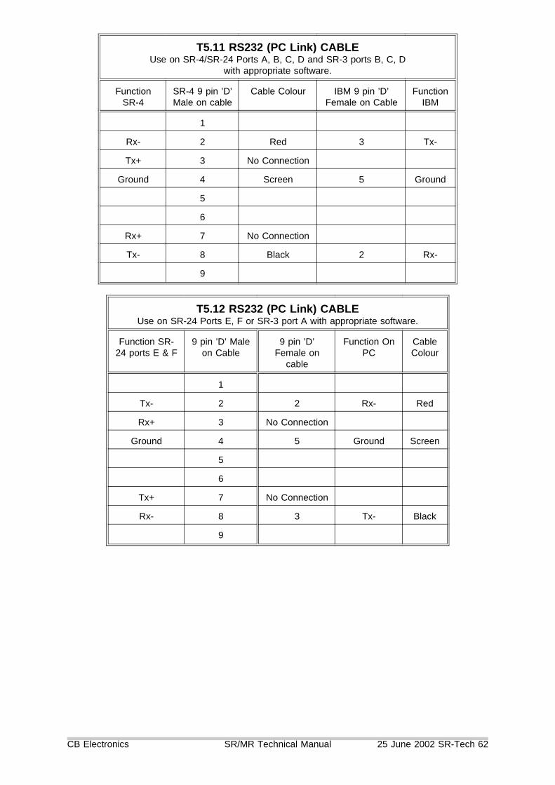
T5.11 RS232 (PC Link) CABLEUse on SR-4/SR-24 Ports A, B, C, D and SR-3 ports B, C, D
with appropriate software.
FunctionSR-4
SR-4 9 pin ’D’Male on cable
Cable Colour IBM 9 pin ’D’Female on Cable
FunctionIBM
1
Rx- 2 Red 3 Tx-
Tx+ 3 No Connection
Ground 4 Screen 5 Ground
5
6
Rx+ 7 No Connection
Tx- 8 Black 2 Rx-
9
T5.12 RS232 (PC Link) CABLEUse on SR-24 Ports E, F or SR-3 port A with appropriate software.
Function SR-24 ports E & F
9 pin ’D’ Maleon Cable
9 pin ’D’Female on
cable
Function OnPC
CableColour
1
Tx- 2 2 Rx- Red
Rx+ 3 No Connection
Ground 4 5 Ground Screen
5
6
Tx+ 7 No Connection
Rx- 8 3 Tx- Black
9
CB Electronics SR/MR Technical Manual 25 June 2002 SR-Tech 62

7.00 Multi Machine Synchronizer Set Up
The SR/MR series of synchronizers offer two forms of synchronisation using eitherthe SR/MR synchronizer or where available the machines built in synchronizer. Theuser interface is identical. The decision "which type of synchronisation to use" dependson the users requirments and the technical details of the machine and the installation.
When a new machine is connected the a system parameter (Unit | Chase | Menu 12System Type) determines which type of synchroniser to use if there is a choice. Onceconnected the user is free to change the synchroniser type. The user selection willonly be changed after a hard reset or if the type of machine connected to the port ischanged.
7.10 Deciding between the SR/MR Synchronizer or the Machine’sbuilt in synchroniser.
1) SR/MR SynchronizerSynchronizing the machine directly using a combination of locate, variplay, shuttle,jog or programable play commands. All machines without internal synchronizers (eg.VTR’s) must synchronized by this method.
2) Machine’s Internal SynchronizerProvide a master timecode feed to the machine then control the machine’s internalsynchronizer. Most audio machines and synchronizers may be controlled in this way(DA-88’s, DAT’s, A820 Digital dubbers, Lynx, TLS, AK ES1.11).
To provide the same functions as the SR/MR synchronizer the machine/externalsynchronizer must accept three commands Chase On, Chase Off (Stop), and SetOffset. providing that these three commands are available the choice ofsynchroniser will make no difference to the user interface.
3) Synchroniser performanceThe SR/MR Synchroniser performance is governed by the available machinecontrol. All professional video recorders must be controlled by their RS422 port inorder to operate with video editors, no conventional video recorder will chasetimecode. Modern audio Recorders are fitted with timecode synchronizers, althoughRS422 ports are fitted, in general they do not always provide the same level ofcontrol as found on video machines are always operated with RS422 control.
If the machine has a built in synchroniser then there will be several factors thatdetermine the choice of synchroniser.
CB Electronics SR/MR Technical Manual 25 June 2002 SR-Tech 63

Determining Factors Use SR/MRSynchronizer
Use MachineSynchronizer
No Synchronizer in Machineeg Tape based Video
Yes No
No Master Timecode feed to machine Yes No
No Video Sync Feed to Machine No Yes
Using Wordclock Reference only limited to +/- 1 framelock accuracy
Yes
Using Wordclock Reference combninedwith Video syncs
Only if machineresolves first to videosyncs’s thenwordclock
Yes
Machine does not accept Chase Oncommand or Set Offset command
Yes No Remotecontrol
Machine does not accept Variplay,shuttle or Programable play commands
No
Machine does not report positionaccurately
No
Machines internal synchronizer is veryslow or has problems
Yes (PCM3324S) No
7.20 Optimisation of the SR/MR Synchroniser.
Video recorders with their powerful servos do not need much optimisation, by defaultthey are parked on the same frame as the master.
Audio recorders often need careful setup in order to achieve fast lockup times. Tosynchronise quickly is necessary to minimise the distance from lock once play speedhas been achieved.
7.21 Sync typeThere are 5 selections of Sync type (IFace | Chase | Menu 43:- Chase Type) asfollows
0= Cmd The machines internal synchronizer is used, The machine must receivea feed of master timecode and accept Chase On and Set Offsetcommands.
1= Play This is a test mode used for setting the Start-up Delay, a Playcommand is sent at the appropriate point, but no attempt is made tosynchronise the machine.
2= PS Not currently implemented
CB Electronics SR/MR Technical Manual 25 June 2002 SR-Tech 64

3= - Using vari-speed commands the machine is slewed to a relativeposition of -1 frame, the machine is then accelerated to becoincident with the master, at this point a Play command is issuedand the machine is released to resolve to video syncs. If an erroris detected within the first 5 seconds of lock the process isrepeated.
4= + Using vari-speed commands the machine is slewed to a relativeposition of +1 frame, the machine is then decelerated to becoincident with the master, at this point a Play command is issuedand the machine is released to resolve to video syncs. If an erroris detected within the first 5 seconds of lock the process isrepeated.
5= -+ Using vari-speed commands the machine is slewed to be coincidentwith the master, at this point a Play command is issued and themachine is released to resolve to video syncs. If an error isdetected within the first 5 seconds of lock the process is repeated.
7.22 Park AheadParking the audio machine ahead of the master machine allows for three commonproblems
1) Audio machines will unlace to protect their heads (eg. DA-88 after 7 seconds).As soon as movement is detected on the master machine the slave is instructed tolace-up, this can take as long as one second.
2) Allows the master timecode to stabilise and correct for any master locate error.
3) An advance play command can be sent earley to the slave and allow for anystartup delay and acceleration time.
The SR/MR allows park ahead of 0 .. 45 frames in 5 frame increments. By default thisis set to one second on tape based audio recorders.
7.23 Machine Start-up Delay (Play/Advance)No mechanical system will start instantly, typically one to seven frames are requiredbetween receiving the Play command until the machine reaches play speed, on slowfilm systems this may be as long as 10 frames. When park ahead is used it is possibleto issue a play command before the master and slave are coincident, but adjusting theplay advance (IFace | Chase | Menu 44:- Start up delay) the difference betweenmaster and slave when the slave achieves play speed may be minimised.
To set the Park ahead set Menu 43:- Chase type to 1= P, in this mode a playcommand will be issued at the appropriate point in time. Repeat using instant replayand adjust for +/- 1 frame error. The optimum error depends on the sync type usedsync type 3 -1 frame, sync type 4 +1 frame, sync type 5 0 frames.
7.24 Pre-Roll
CB Electronics SR/MR Technical Manual 25 June 2002 SR-Tech 65

When more than one machine is used it will take time for all machinesto becomesynchronised after a play command is issued. A user defined pre-roll is used with the[Auto] and [Rehearse] commands and may also be used with the [Locate]commands. The Pre-Roll is set by entering the desired value then [Store] followedby [<] (Reverse Play). The default [Locate] is to locate with pre-roll, [Shift] followedby locate will locate without pre-roll. Setup | Root | Generic | Menu 28: Locate withPre-roll may be used to reverse this.
7.25 Post RollPost-Roll is used to ensure that the exit from record is always clean. The Default postroll is 12 frames. Post-Roll may be set using [Store] followed by [>] (Play).
7.26 DelayDelay is used to allow external machines or the Talent and even the operator time tocatch up after a locate. The default delay is one second, to set the delay use [Store]followed by [Stop].
7.30 Setting up the System
7.31 Defining the MasterAny machine on the system, the generator or the reader may be defined as themaster. The master machine is defined using [Shift] followed by a machine key (A,B, C, D, E (SR-24)), [Reader] or [Generator]. Once the master has been defined andoffsets set for all the slaves the master machine may be changed as required. Note:on MR systems only machines controlled directly by the controller may be defined asa master machine and not machines controlled by the MR-3’s.
The master of a multi-machine system is the machine to which all commands are sent.The other chase enabled machines then follow the selected master.
The master is the machine over which the user has direct control. Each user has hisown reasons for selecting a particular machine as master, here are some:-1) Film because it is the slowest.2) Video so that the user can jog the picture directly.3) The record machine so that it is first to lock.4) A machine that slaves badly or not at all.5) The Generator as a perfect machine.6) The Reader where the master is not directly controlled.
The system will only operate correctly if the selected master is resolved (locked) tovideo syncs.
Note. When configured as a SR-3, where [A] is an input ([E] on the SR-24) [A]should never be defined as the master. This is an input and not anoutput. Any controller connected to this input will controll the selectedmaster machine.
Pefect Master ModeThe timecode generator may be selected as the master (Shift followed by Gen(Macro 118)) to enter the perfect machine mode. The generator may be used as a
CB Electronics SR/MR Technical Manual 25 June 2002 SR-Tech 66

timecode master in a tapeless studio. To set the value of the timecode generatoruse the Locate/Shift Locate command.
Remote Master ModeThe timecode reader may be selected as the master ([Shift] followed by [Reader].This is used when you have a remote source of code only. Not the code should beresolved to the same video reference as the studio.
7.32 Defining a Machine as a SlaveA machine may be selected to be a slave by selecting the machine (A, B, C, D orE) and using [Chase/Offset] or [Shift] followed by [Chase/Offset]. When the shiftkey is used the current Master slave Positions are used to calculate the SlaveOffset.
7.33 ENTERING A OFFSETTo enter an offset, first select the machine (A, B, C, D or E) then type in the offsetrequired, this will be displayed on the lower right hand display. Then use the Storekey followed by the Chase/Offset key. The display will confirm by displaying offsetnext to the displayed number.
7.34 TRIMMING A OFFSETTo trim an offset (or any other memory) first type in the trim required, this will bedisplayed on the right of the lower line. Then use the Trim+ or Trim- key followedby the Chase/Offset key. The display will confirm by displaying the new offset.
7.35 ENTERING A NEGATIVE OFFSETOn the SR and MR series remotes all offsets are calculated on a twenty-four hourclock. To enter a negative offset either calculate the required offset by subtractingfrom 00:00:00:00 (-01:00:00:00 = 23:00:00:00) you can use the SR-4 to perform thecalculation as follows:-
1) Zero the keyboard display: Shift followed by Clear/02) Zero the offset: Store followed by Chase/Offset.3) Type the required negative offset.4) Subtract: Trim- followed by Chase/Offset.
7.36 SR/MR TIMECODE GENERATOR OUTPUTSThe SR/MR timecode generator is an integral part of the synchronization system.The timecode value follows the position of the selected master machine (includingthe timecode reader). If Group Locates are enabled the timecode generator willjump to the Locate point allowing chase machines to locate individually. Thetimecode output is also used to roll over any drop-outs in the machine timecode.
Two separate outputs are avalable from the generator as follows:-
Output 1) This output is always available. and is used by chase sync machines.
Output 2) This output is enabled only when the Master is in locked play and isnormally used for the automation system.
The timecode generator timecode value is calculated as follows:- [Timecode Output]= [Master Position] - [Master Offset]. Including the master offset in the calculation
CB Electronics SR/MR Technical Manual 25 June 2002 SR-Tech 67

allows the user to change the master without having to update the slave offsets, orchange the settings for any other units connected to the SR-4 timecode output(Automation, Midi, Chase only slaves...).
7.37 Some Common Terms
a) Virtual Master / Perfect MachineWhen a timecode Genearor is used as the master and all machines are slaved tothe generator the term Virtusl Master of Perfect Machine is often used. The mainadvantage of the Virtual master is that it lockes instanstly when entering play. Thedisadvantage of a erfect master system is that all machines must be slaves.
b) Group LocatesWhen locating a number of machines there are two choices, either they can locateindividually or they can all chase the current master machine. The main advantageof group locates is that locates are faster because the ’chasing machines do nohave to wait until the master has cued.
CB Electronics SR/MR Technical Manual 25 June 2002 SR-Tech 68

T9.0 Video Synchroniser (VS-1) Interface
T9.01 Video Streamer Setup1) The time taken by the wipe is calculated as Beats*60/BPM.2) The Record/Lock display is enabled/disabled on the streamer by Mode | 5 | 5| 4
T9.02 SR Wipe-length Setup1) The Wipe length must be stored in keyboard memory Shift-9 in seconds andframes.2) Wipes will be triggered to finish at the record in point and keyboard memory-9.
T9.03 Video Streamer Interface to the SR SystemThe VS-1 connects to the SR system via the GP Outputs and the master timecodeoutput. The GP outputs on the SR are active High, the VS-1 has active low opto-isolator inputs. Diagram SR-VS1 shows a suitable interface circuit.
T9.04 Video Streamer Interface to the MR SystemThe VS-1 is connected to the MR-BUS Serial A and B are connected in parallel sothat you may link the bus to other units.Note. The streamer will be activated on all cue points stored in its memory after the
current in point.
CB Electronics SR/MR Technical Manual 25 June 2002 SR-Tech 69

SR-3 and SR-4 Connections
CB Electronics SR/MR Technical Manual 25 June 2002 SR-Tech 70

SR-24 and SR-32 Connections
CB Electronics SR/MR Technical Manual 25 June 2002 SR-Tech 71

Link positions for SR-3 and SR-4
CB Electronics SR/MR Technical Manual 25 June 2002 SR-Tech 72

S29
Par
alle
lre
mo
teC
on
nec
tio
ns
(SR
-24A
&S
R-3
2O
nly
)
CB
Ele
ctro
nics
SR
/MR
Tec
hnic
alM
anua
l25
June
2002
SR
-Tec
h73

CB
Ele
ctro
nics
SR
/MR
Tec
hnic
alM
anua
l25
June
2002
SR
-Tec
h74


![B. Tech (Electronics & Telecommunication …...B. Tech (Electronics & Telecommunication Engineering) Proposed Curriculum for Semester VI [Third Year] Sr. No. Course Code Type of Course](https://img.pdfslide.net/doc/110x75/5e99aea7e8ac9c02686a7daa/b-tech-electronics-telecommunication-b-tech-electronics-telecommunication.jpg)