Embed Size (px)
Citation preview
CB59 – CB60 - CB61
User's manual
CB59CB60CB61
Description
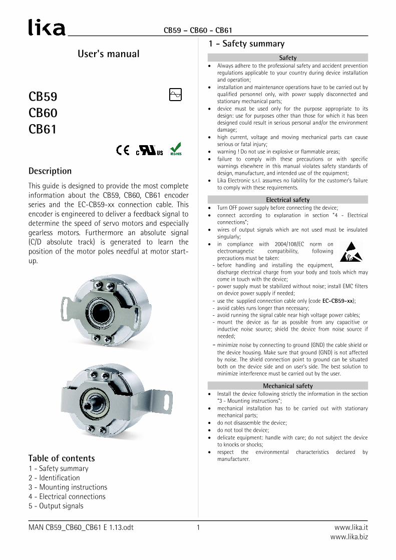
This guide is designed to provide the most complete information about the CB59, CB60, CB61 encoder series and the EC-CB59-xx connection cable. This encoder is engineered to deliver a feedback signal to determine the speed of servo motors and especially gearless motors. Furthermore an absolute signal (C/D absolute track) is generated to learn the position of the motor poles needful at motor start-up.
Table of contents1 - Safety summary2 - Identification3 - Mounting instructions4 - Electrical connections5 - Output signals
1 - Safety summarySafety
Always adhere to the professional safety and accident prevention regulations applicable to your country during device installation and operation;
installation and maintenance operations have to be carried out by qualified personnel only, with power supply disconnected and stationary mechanical parts;
device must be used only for the purpose appropriate to its design: use for purposes other than those for which it has been designed could result in serious personal and/or the environment damage;
high current, voltage and moving mechanical parts can cause serious or fatal injury;
warning ! Do not use in explosive or flammable areas; failure to comply with these precautions or with specific
warnings elsewhere in this manual violates safety standards of design, manufacture, and intended use of the equipment;
Lika Electronic s.r.l. assumes no liability for the customer's failure to comply with these requirements.
Electrical safety Turn OFF power supply before connecting the device; connect according to explanation in section ”4 - Electrical
connections”; wires of output signals which are not used must be insulated
singularly; in compliance with 2004/108/EC norm on
electromagnetic compatibility, following precautions must be taken:
- before handling and installing the equipment, discharge electrical charge from your body and tools which may come in touch with the device;
- power supply must be stabilized without noise; install EMC filters on device power supply if needed;
- use the supplied connection cable only (code EC-CB59-xx);- avoid cables runs longer than necessary;- avoid running the signal cable near high voltage power cables;- mount the device as far as possible from any capacitive or
inductive noise source; shield the device from noise source if needed;
- minimize noise by connecting to ground (GND) the cable shield or the device housing. Make sure that ground (GND) is not affected by noise. The shield connection point to ground can be situated both on the device side and on user’s side. The best solution to minimize interference must be carried out by the user.
Mechanical safety Install the device following strictly the information in the section
“3 - Mounting instructions”; mechanical installation has to be carried out with stationary
mechanical parts; do not disassemble the device; do not tool the device; delicate equipment: handle with care; do not subject the device
to knocks or shocks; respect the environmental characteristics declared by
manufacturer.
MAN CB59_CB60_CB61 E 1.13.odt 1 www.lika.itwww.lika.biz

CB59 – CB60 - CB61
2 - Identification
Device can be identified through data (order code and serial number) available in the label applied to its body. Information is listed in the delivery document. For any information on the technical characteristics of the product, refer to the technical catalogue.
3 - Mounting instructions
WARNING: installation and maintenance operations have to be carried out by qualified personnel only, with power supply disconnected and
mechanical parts absolutely in stop. Do not tool the unit.
3.1 Installing the encoder
For correct installation a M5-threaded bore has to be provided in the motor shaft (see Figures below).
To install the encoder please follow carefully the next steps: unscrew the plastic cap (reference 3) on the
back of the encoder; insert the encoder in the motor shaft and fix it
using the provided M5 screw (reference 1); replace and tighten the plastic cap (reference 3)
you previously removed; fasten the encoder to the motor frame through
the fixing plate using the M3 screws (reference 2).
MAN CB59_CB60_CB61 E 1.13.odt 2 www.lika.itwww.lika.biz
Figure 2 - CB60
Figure 1 - CB59

CB59 – CB60 - CB61
3.2 Dismounting the encoder
To dismount the encoder please follow carefully the next steps: unscrew the fixing plate from the motor frame; remove the plastic cap 3 on the back of the
encoder; remove the M5 screw 1 which fixes the encoder
shaft to the motor shaft.
WARNING: do not force the encoder manually to pull it out!
tighten a M6 screw instead of the M5 screw in the encoder shaft while ensuring the motor does not move (tightening the M6 screw will cause the encoder shaft to be drawn out slowly). To prevent the thread of the motor shaft from being damaged we suggest tightening a M5 grub screw before screwing in the M6 screw.
4 - Electrical connections
TF12 cable specificationsTwisted pairs : 6 x 2 x 28AWGShield : braided copperOutside Ø : Ø 5.4 mm ± 0.1Impedance : <242 Ohm/Km (20°C)
(UL 758 tab.5.2.1)
Function TF12 cable+5VDC ±5% Brown_Green
0VDC White_GreenA Red/A BlackB Green/B BrownC * Violet/C * YellowD * Grey/D * Pink0 White/0 Blue
Shield Case
* C/D signals of the absolute track are available with option /1 only, see the order code
A, B signals: Incremental sine/cosine, 2048 pulses at each complete turn of the encoder shaft.
WARNING: C/D signals of the absolute track are available with option /1 only, see the order code
C, D signals: Absolute sine/cosine track, 1 sinusoidal period at each complete turn of the encoder shaft.
0 signal: Index "Z-track", 1 pulse at each complete turn of the encoder shaft.
5 - Output signals
The frequency of the output signals is proportional to the shaft rotational speed.
If “Pulse rate” is 2048/x (see order code), then the encoder provides 2048 A and B sinusoidal pulses + Z track at each turn.
The encoder provides one C and D absolute sinusoidal signals at each turn (absolute track) only if “Pulse rate” is 2048/1 (see order code).
MAN CB59_CB60_CB61 E 1.13.odt 3 www.lika.itwww.lika.biz

CB59 – CB60 - CB61
5.1 Output signals level
The voltage level refers to the differential value between normal and inverted signal (differential).
Recommended input circuit
Encoder Input circuit
VREF = 2.5V ± 0.5V VA = 1Vpp · Av Av = R2/R1
Document release
Description
1.0 1st issue1.1 Added example in section 51.2 Updated paragraph 6.11.3 Updated section 41.4 Updated sections 1, 3.1 and 41.5 Added CB601.6 Updated section 41.7 Updated section 41.8 Updated sections 1 and 3.11.9 Added CB611.10 Updated section 41.11 Updated section 31.12 Web links updated
1.13Italian / English separate editions, new option /0 without absolute track
This device is to be supplied by a Class 2 Circuit or Low-Voltage Limited Energy or Energy Source not exceeding 30VDC. Refer to the product datasheet for supply voltage rate.
LIKA ElectronicVia S. Lorenzo, 25 - 36010 Carrè (VI) - Italy
Tel. +39 0445 806600Fax +39 0445 806699
Italy: eMail [email protected] - www.lika.itWorld: eMail [email protected] - www.lika.biz
MAN CB59_CB60_CB61 E 1.13.odt 4 www.lika.itwww.lika.biz