Embed Size (px)
Citation preview

1. Anticlockwise
2. Metal A , because 𝜈𝑜′ > 𝜈0
3. The ampere is the value of that steady current which, when maintained in each of the two very long,
straight, parallel conductors of negligible cross-section, and placed one metre apart in vacuum,
would produce on each of these conductors a force equal to 2 × 10⁻⁷ newtons per metre of length.
4. The lens will behave as a diverging lens. The lens is of refractive index lesser than the medium in
which it is placed. Hence, its nature does not change.
5. Electric field line is a curve drawn in such a way that the tangent to it at each point is in the direction
of the net field at that point. Two fields can never cross each other. If they did ,it means the field at
the point of intersection will not have a unique direction, which is meaningless)
6. The frequency belongs to microwave region of the electromagnetic spectrum.
7. Neutrinos interact very weakly with other particles. Since they can penetrate large quantity of
matter without interacting they remain undetected throughout the experiments.
8. a.c. voltage is preferred over d.c. because
(i) a.c. voltages can be easily stepped up or down with the help of transformers.
(ii) Electrical energy can be transmitted efficiently and economically over long distances
with higher voltage and lower current.
9. Consider the charging of a capacitor. The electric field between the plates of the capacitor is shown
below
If the plates of the capacitor have an area A and a total charge Q, the magnitude of the electric
field between the plates is
CBSE Class 12 Physics Sample Paper Solution Set 2

0A
QE
The field is perpendicular to the surface S as shown in the figure. Thus, using Gauss’s law the
electric flux through the surface is
00
Q
A
QAAEE
Now, if the charge Q on the capacitor is changing with time, there is a current dt
dQi
associated with it, so we have
idt
d
dt
dQQ
dt
d
dt
d
E
E
0
00
1
This term is the current due to changing electric field and is called displacement current. Thus,
the Ampere’s Circuital law is modified to give
dt
dφεμiμB.dl c 000
10. Given:
27
19
328
5102
1061
109
72
m.A
C.e
mn
A.I
The drift speed is given as
m/s.
..
.
neA
Ivd
4
719281057
10521061109
72
11. The terminal voltage across a cell is given as
V = E - Ir Here, E is the e.m.f. of the cell and r is its internal resistance.
The above equation is of the form y = mx + c where y = V, m = -r, x = I and c = E
Hence, the graph of V vs I will be as shown below.

From the graph, it is clear that the y-intercept, that is, the intercept on V-axis gives the value of
e.m.f. (E) of the cell. Also, the negative of slope of the graph gives the internal resistance (r) of
the cell.
12. The capacitance of two capacitors is same, i.e. C.
The voltage across charged capacitor is V1 = V and that across uncharged capacitor is V2 = 0.
Thus, the initial energy stored in the capacitor is
22
1112
1
2
1CVVCU
When the charged capacitor is connected across the uncharged capacitor, the two capacitors
form a parallel combination.
Thus, the resultant capacitance is C’ = C + C = 2C
The initial charge on the capacitor is q = CV
The final potential across the combination will be
222'' 21 V
C
CV
C
q
C
qqV
Hence, the final energy in the combination of capacitors is
22
1
8
2
22
2
12''
2
1 222
2
CVCVVCVCU
Thus, the ratio of energy stored in the combined system to that in the initial single capacitor is
given as
2
1
2
122
1
2
2
1
2
CV
CV
U
U
13. The Rutherford model of atom considers the atom as an electrically neutral sphere consisting of a
very small, massive and positively charged nucleus at the centre surrounded by the revolving
electrons in their respective dynamically stable orbits.
The electrostatic force of attraction Fe between the revolving electrons and the nucleus provides
the centripetal force Fc to keep them in stable orbits.

2
0
2
2
2
0
2
4
4
1
mv
er
r
e
r
mv
FF ce
The kinetic energy and electrostatic potential energy of the electron in hydrogen atom are
r
eU
r
emvK
0
2
0
22
4
82
1
Thus, the total energy E of the electron in a hydrogen atom is
r
e
r
e
r
eUKE
0
2
0
2
0
2
8-
48
The total energy is negative.
The significance of this negative energy is that the electron is bound to the nucleus. If it is
positive, then the electron will not follow a closed orbit around the nucleus.
OR
To find the expression of radius, Bohr’s second postulate is used. The expression of angular
momentum is
L =mvr
Bohr’s second postulate of quantisation says electron revolves only in those orbits for .which
the angular momentum is integral multiple of h/2π.
2
nhL
Thus, for electron in nth orbit
2
nhrmvL nn ……(1)
The relation between velocity and radius for electron in nth orbit is
n
nmr
eV
04 …..(2)
From equations (1) and (2), we get
n
n
mv
nhm
eV
24 0

2/
1
4V
2/4
0
2
n
0
2
2
hn
e
hn
veV n
n
……(3)
Substituting (3) in (1), we get
2
0
22 4
2 e
h
m
nrn
….(4)
This gives the radius of electron in the nth orbit From equation (4), the radius of innermost orbit
n = 1 is found as
2
0
2
1me
hr
This is called the Bohr radius and is denoted as a0.
14. (i) Field lines around a paramagnetic substance
Paramagnetic substances are those which get weakly magnetised when placed in an external
magnetic field. They have a tendency to move from a region of weak magnetic field to strong
field, that is, they get attracted to a magnet. Hence, when placed in magnetic field, the field
lines get concentrated inside the material.
(ii) Field lines around a diamagnetic substance
Diamagnetic substances are the ones in which resultant magnetic moment of an atom is zero.
When magnetic field is applied, those electrons having orbital magnetic moment in the same
direction slow down and those in the opposite direction speed up. This happens due to induced
current in accordance with Lenz’s law. Thus, the substance develops a net magnetic moment in
direction opposite to that of the applied field and hence repulsion is seen.

15. Principle: A junction diode offers a low resistance to current in one direction and a high resistance in
the other direction. Thus, the diode acts as a rectifier. Half-wave rectifier: When the diode rectifies
only half cycles of the AC wave, it is called half-wave rectifier.
The figure shows the arrangement for using diode as half-wave rectifier. The alternating input
signal is fed to the primary of a transformer. The output signal appears across the load
resistance RL. When the voltage at A is positive, diode is forward biased and it conducts. When
voltage at A is negative, diode is reverse biased and it does not conduct. During the positive half
of the input signal, the diode is forward biased. The flow of current in the load resistance RL is
from X to Y. During the negative half of the input signal the diode is reverse biased. The current
does not flow through the load resistance.
16.
17. The n-p-n transistor as amplifier in CE configuration is shown below

The transistor will work as an amplifier if its operating point is somewhere in the middle of
active region.
18. (i) Receiver: A receiver extracts the desired message signals from the received signals at the channel
output.
(ii) Demodulator: A demodulator retrieves information from the carrier wave at the receiver.
19. The ray diagram for the image formed by the combination of lens and mirror is shown below.
For the convex lens, we have
u1 = - 40 cm and f = + 20 cm
Hence, using lens formula we get.
cmv
v
v
ufv
fuv
40
40
11
40
1
20
11
111
111
If only the lens was present, then the image would have formed at Q1. But, now this image acts
as a virtual object for the convex mirror such that
O’Q1 = distance of virtual object from convex mirror = OQ1 – OO’ = 40 – 15 = 25 cm
Hence, for the convex mirror u2 = +25 cm and R = + 20 cm
Using mirror formula, we get

cmv
v
v
uRv
Ruv
20
20
11
20
1
20
21
121
211
Hence, the final image is formed at Q which is 20 cm behind the mirror.
20. The de Broglie wavelength of the electron,
nmVmeV
h 227.1
2
Given:
V = 50 Kv = 50 x 103 V
m.htyellow ligλ
nm. λ
nm.
λ
-
7
12
3
1095
1055
1050
2271
Resolving Power (RP) is inversely proportional to wavelength. Thus,RP of an electron microscope
is about 105 times that of an optical microscope. In practice, differences in other (geometrical)
factors can change this comparison somewhat.
21.
Insulator Conductor Semiconductor
Energy band gap Eg is very large. (Eg >3 eV)
In conductors, conduction band and valance band are partially filled or overlap each other.
Energy band gap Eg has finite but small value. (Eg < 3 eV)
Electrical conduction is not possible as there are no electrons in the conduction band.
Conductors have low resistance or high conductivity.
Resistance of semiconductors is not as high as that of the insulators.
22. Basic modes of communication:
There are two basic modes of communication: (i) Point – to – point (ii) Broadcast Amplitude
modulation: In amplitude modulation, the amplitude of the modulated signal is varied in
accordance with the amplitude of the modulating signal so that the frequency of the modulated
wave is equal to the frequency of the carrier waves.

Diagram:
23. (a) Resistance of a wire is inversely proportional to the cross sectional area of the wire. If the copper
strips are not thick, then their resistances have to be included in the respective ratio arms.
Therefore, copper strips are made thick so that their resistances can be safely ignored.
(b) The percentage error in R is given as,
1
1
100 I
ISR
The percentage error in R can be minimised by adjusting the balance point near the middle of
the bridge. i.e., when l1 is close to 50 cm
(c) ) Meter bridge wire is made of an alloy such as manganin. It is because; an alloy has high
resistivity and a low value of temperature coefficient of resistance.
resistivity and a low value of temperature coefficient of resistance.
OR
The sliding contact is in the middle of the potentiometer. So, only half of its resistance R0/2 will
be between the points A and B. Hence, the total resistance between A and B say R1 will be given
as
RR
RR
RR
RR
RRR
2R
2
2/
111
0
0
1
0
0
01
……..(1)
The total resistance between A and C will be the sum of resistance between A and B and B and
C, i.e., R1 + R0/2. Therefore, the current flowing through the potentiometer will be
0101 2
2
2/ RR
V
RR
VI
The voltage V1 taken from the potentiometer will thus be given as
1
01
112
2R
RR
VIRV
…….(2)
Substituting (1) in (2), we get

RR
VR
RRR
VR
RR
RR
RRR
RR
VV
4
2
22
2
2
22
2
0
0
0
0
0
0
0
1
24. (a) Aarti showed presence of mind, awareness, critical thinking, decision making, persuasive power
and caring nature towards her sister.
(b) Doctors diagnose brain tumour by MRI or CT scans. These techniques involve taking pictures
of the brain. Sometimes a special dye made of a radioisotope is injected into the vein of the
brain. This dye highlights the various tissues of the brain enabling the doctors to visualise the
scan in a better way and helps them in the detection of brain tumour.
25. (a) Consider the rod moving in the presence of magnetic field as shown below.
The rod PQ is moved towards left with constant velocity v. We assume that there is no loss of
energy due to friction. PQRS forms a closed circuit enclosing an area that changes as PQ moves.
It is placed in a uniform magnetic field B which is acting downwards and perpendicular to the
plane of the system. If the length PQ = l and RS = x, the magnetic flux enclosed by the loop PQRS
will be B = Blx
Since, x is changing with time the rate of change of flux will induce an e.m.f. as given by
Blvdt
dxBlBlx
dt
d
dt
d B
Here, .vdt
dx The negative sign indicates that x is decreasing with time.

This is the expression of the induced e.m.f. which is also called the motional e.m.f.
(b) This motional e.m.f. can be explained by invoking Lorentz force acting on the free chargecarriers of conductor. Consider any arbitrary charge q in the conductor PQ. When the rod moveswith speed v, the charge also moves with speed v in the magnetic field B. The Lorentz force onthis charge is qvB in magnitude, and its direction is towards Q.The work done in moving the charge from P to Q will beW = qvBlNow, e.m.f. is the work done per unit charge. Hence, we have
Blvq
W
This is the equation of motional e.m.f.
26. (a)
(b) The incident light is unpolarised. The intensity of light, on being transmitted through the firstpolaroid is;
2
01 cosII
2
1cos
2
201
II
If θ is the angle between the transmission planes of the two polaroids, then the intensity I' of light on passing through the second polaroid is given by
I = I1 cos2θ The polaroid P is kept in between P1 and P2. Hence, the intensity of light transmitted through P3 is;
I3 = I1 cos2θ
82
1
260cos
2I
60 and 2
0
2
0020
3
00
1
III
II
The angle between the transmission planes P3 and P2 is 30°.

⇒ I2 = I3 cos2θ
0
2
0020
2
00
3
32
3
2
3
830cos
8I
308
III
and θI
I
Hence,
002
0
0
3
0
0
1
091.032
3
125.08
5.02
III
II
I
II
I
27. For an AC circuit, average power is calculated by defining the instantaneous power of the circuit.The instantaneous power of an AC circuit is defined as the product of the instantaneous e,m.f andinstantaneous current in it.
A Voltage V = V0 sin ωt applied to a series LCR circuit drives a current in the circuit given by ).
i =i0 sin (ωt + ).
R
XX
Z
Vi LC1-0
0 tan and
Where, Φ is the phase angle by which current leads the e.m.f. in an AC circuit. V0 and i0 are, the peak values of e.m.f. and current respectively. XL is the inductive reactance, XC is the capacitive reactance and Z is the total resistance of the circuit.
The instantaneous power p supplied by source is p = V i p = (V sinωt) × [i0 sin (ωt +Φ)]
tiV
p 2coscos2
00 ……(1)
The average power over a cycle is given by the average of the two terms in equation (1). The second term cos (2ωt +ϕ) is time–independent. Its average is zero as the positive half of the cosine cancels the negative half.
3....cos p
2..... cos VIp
cos22
cos2
iVp
2
0000
ZI
iV
Equation (3) is the required expression for average power dissipated over a cycle. Average
power dissipated depends on voltage, current and the cosine of the phase angle
(i) When cos Φ = 0, no power is dissipated even though a current is flowing in the circuit.For purely inductive and capacitive circuit, the phase difference between current and
voltage is π/2. Therefore, cos Φ=0

This current is called as wattles current. (ii) If the circuit contains only pure R, it is called purely resistive circuit. In that case Φ =0,
cos Φ=1
p = I2Z = Maximum dissipated power
28. (a) Consider two coherent sources of light S1 and S2 are placed at a distance d apart. Distancebetween screen and the plane of the two sources is D. The spherical waves coming from S1 and S2produces interference fringes on the screen GG’ as shown in the figure below.
Let P be an arbitrary point on the line GG’. The path difference between the light waves reaching at point P from the sources S1 and S2 is; S2P – S1P = nλ; n = 0,1,2,3...... ..........(1)
(S2P)2 -(S1P)2 =
2
2
2
2
22
dXD
dXD
= 2xd Where S1S2 = d and OP = x
PSPS
xdPSPS
12
12
2
……(2)
In practice, the point P lies very close to the centre of screen O. Therefore, S2P ≈ S1P ≈ D (If x,d << D)
Hence, negligible error will be introduced if 2 1 S2P + S1P is replaced by 2D. From (2),
S2P – S1P ≈ D
xd............(3)
Hence, Condition for constructive interference resulting in a bright region is;
x = xn =d
Dn ; n = 0, ± 1, ± 2, ............
Condition for destructive interference resulting in a dark region is;

x = xn = d
Dn
2
1 + ; n = 0, ± 1, ± 2, ............
The dark and bright bands appearing on the screen are called fringes. Dark and bright fringes are equally spaced and the distance between two consecutive bright and dark fringes is given by, β = xn+1 - xn
Or d
D ……(4)
Equation (4) is the required expression for the fringe width.
(b) When two light waves of amplitudes a and a differing in phase by φ interfere, the intensity ofthe resultant light is given by,
I = a12 +a2
2 +2a1 a2 cos φ The intensity of light will be maximum, when φ = 0
Imax = a12 +a2
2 +2a1 a2 cos 0 = a1
2 +a22 +2a1 a2 x 1
Imax = (a1+a2)2
The intensity of light will be minimum, when φ = π Imin = a1
2 +a22 +2a1 a2 cos π
= a12 +a2
2 +2a1 a2 x (-1) Imin = (a1-a2)
2 Hence,
2
21
2
21
min
max
)a-(a
)a(a
I
I
Given : Imin : Imax=9:25
1
4
35
35
)a(a)a(a
)a(a)a(a
3
5
)a(a
)a(a
9
25
)a-(a
)a(a
I
I
2
1
2121
2121
21
21
2
21
2
21
min
max
a
a
Slit width w α a2
1:16:
1
16
21
2
2
2
1
2
1
ww
a
a
w
w
OR (a)

Consider that a monochromatic source of light S, emitting light waves of wavelength λ. As shown in figure, a parallel beam of light is falling normally on a single slit LN of width a. M is midpoint of the slit. The diffraction pattern is obtained on a screen lying at a distance D from the slit.
The path difference between the two edges of the slit is given as, Path difference = NP – LN
= NQ = a sin θ
≈ aθ ( ∵ θ is very small)
It is observed that, the diffraction pattern has a central maximum at C flanked by a number of dark and light fringes called secondary maxima and minima on either side of the point C.
Intensity has a central maximum at θ = 0. The angle θ is zero at the central point C on the screen. At C all the path differences are zero and hence all the parts of the slit contribute in phase.
Consider the angle θ for which the path difference aθ is λ.
a
……(1)
Now, divide the slit into two equal halves LM and MN each of size a/2. For every point M1 in LM, there is a point M2 in MN such that M1 M2 = a/2.
The path difference between M1 and M2 at P = M2P - M1P

2
2
a
This means that the contributions from M1 and M2 are 180ᵒ out of phase. Hence, contributions from the two halves of the slit LM and MN cancel each other and the intensity falls to zero for that particular chosen angle.
Similarly, the intensity is zero fora
n , with n being any integer except zero.
Now, consider an angle 2a
3 which is midway between two of the dark fringes. Divide
the slit into three equal parts. If we take the first two thirds of the slit, the path difference between the two ends would be,
a
aa
2
3
3
2
3
2
The first two – thirds of the slit can therefore be divided into two halves which have a 2
path difference. The contributions of these two halves cancel each other. Only the remaining one – third of the slit contributes to the intensity at a point between the two minima which will be much weaker than the central maxima.
Similarly, it can be shown that there are maxima at .2
1
an
The intensity of the secondary maxima goes on decreasing with the order of maxima.
Condition for secondary minima:
.3,........ ,2 ,1; na
n
Condition for secondary maxima:
.3,........ ,2 ,1 ;2
1
n
an
(b)
Distance between the nth secondary maximum from the center of the screen is given as,
a
Dn
a
Dnyn
2
12
2
1
For the first maxima,

12
31 n
a
DY
λ1 90 nm = 5900 x 10-10 m λ 2 596 nm = 5960 10-10 m D = 1.5 m a = 2 x 10⁻⁶ m
y1 (λ1 = 590 nm)
m.
.
a
Dλ
nmλy
m.
.
a
Dλ
67050
1022
105960513
2
3
596
66370
1022
105900513
2
3
6
10
2
21
6
10
1
Hence, separation between the positions of first maxima of the diffraction pattern obtained in the two wavelengths is
= 0.6705 – 0.6637 = 0. 0068 m
= 6.8 mm
29. (a) Consider a particle of charge q and mass m revolving in a circular path in thepresence of magnetic field of strength B. The radius of the path is r and its speed of revolution is v. Now, the centripetal force necessary for circular motion is provided by the Lorentz
force on charge q due to B.
FC = FL
qB
mvr
qvBr
mv
2
Now, the time required to traverse the entire circle is

qB
m
qB
mv
vT
v
r
rvT
22
2
/
22
Thus, the frequency of revolution of the charged particle is
m
qB
Tvc
2
1
Hence, from the above expression, we can see that the frequency of revolution of a charged particle in a magnetic field is independent of velocity or energy of the charged particle.
(b) The schematic diagram of a cyclotron is shown below.
Construction: A cyclotron consists of two D-shaped semicircular hollow metallic chambers called ‘dees’. The two dees are placed horizontally with a small gap separating them. The two
dees are connected to a source of high frequency electric field. The whole apparatus is
placed between two poles of a strong electromagnet with the field perpendicular to the plane of the dees. Consider a positive ion produced at the centre of the gap at the time when dee D1 is at positive potential and dee D2 is at negative potential. The positive ion moves from dee D1 to D2. As the magnetic field acts normally to the motion of positive ion, the ion experiences
force. The force on the positive ion due to magnetic field provides the centripetal force

to the ion and it deflects along a circular path.
After moving along the semicircular path inside D2, the ion reaches the gap. At this stage the polarity of the dees reverses due to alternating electric field. The positive ion gains energy as it is attracted towards D1. After traversing the path along D1, the ion again reaches the gap and gets attracted by D2 as the polarity is reversed again. Hence, the ion gains energy again. This process repeats and at each stage the particle is accelerated.
OR (a) Moving coil galvanometer Principle: A current carrying coil suspended in a magnetic field experiences a torque.
Working: When current is passed say long ABCD, the couple acts on it. AB experiences outward force and CD, the inward force in accordance with Fleming’s left hand rule.
Since the plane remains always parallel to the magnetic field in all position of the coil (radial field), the forced on the vertical arms always remains perpendicular to the planeof the coil.
Let I = the current flowing through coil.
B = magnetic field supposed to be uniform and always parallel to the coil.
l = length of the coilb = breadth of the coilN = no. of turns in the coil
Deflecting torque acting on the coil is τ = NIBlbsin900 = NIBlb x 1 = NIBA where A = lb = area of the coil.

Due to deflecting torque, the coil rotates and suspension wire gets twisted. A restoring torque is set up in the suspension wire. If θ is angle through which the coil rotates and k is the restoring torque per unit angular twist (torsional constant), then Restoring torque, τ = kθ In equilibrium,
Defecting torque = Restoring torque NIBA = kθ
Or, G
NBA
kI
Where G = k/NBA, is the galvanometer constant.
∴ I ∝ This provides a linear scale for the galvanometer.
(b) (i) To produce radial magnetic field, pole pieces of a permanent magnet are madecylindrical and a soft iron core is placed between them. The soft iron core helps in making the field radialand reduces energy losses due to eddy currents.(ii) The voltage sensitivity as deflection per unit voltage is given as
Rk
NAB
I
1
The current sensitivity is given as
k
NAB
I
When we double the number of turns, N → 2N, then we get
II
2
Thus, the current sensitivity doubles. However the resistance of the galvanometer also doubles as resistance is directly proportional to length. So the voltagesensitivity remains unchanged
VRk
NAB
V
2
12
Hence, increasing the current sensitivity does not increase the voltage sensitivity.
30.

CBSE 2016
Principle: 1) The charge always resides on the outer surface of hollow conductor.2) The electric discharge in air or gas takes place readily at the pointed ends of theconductors.
Construction: It consists of a large hollow metallic sphere S mounted on two insulating columns and an endless belt made up of rubber which is running over two pulleys P1 and P2 with the help of an electric motor. B1 and B2 are two sharp metallic brushes. The lower brush B1 is given a positive potential by high tension battery and is called a spray brush, while the upper brush B2 is connected to the inner part of the sphere S.
Working: When brush B1 is given a high positive potential then it produces ions due to the action of sharp points. Thus, the positive ions so produced get sprayed on the belt due to repulsion between positive ions and the positive charge on brush B1. Then it is carried upward by the moving belt. The pointed end of B2 just touches the belt, collects the positive charge and makes it move to the outer surface of the sphere S. This process continues and the potential of the shell rises to several million volts.
Uses: (1) It can be used to separate different charges.(2) It can be used to accelerate particles like protons, α particles, etc. to high speeds and energies.
Limitations: (1) It cannot be used to generate potential more than 7 million volts.(2) There is only one sided movement available for the charges due to series connection.
OR
(a) Consider an electric dipole placed in uniform electric fieldE . The axis of dipole
The force acting on charge +q at B is +q E
in the direction of E
and the force acting on
charge –q at A is –q E
in the direction opposite to E
.
These two equal, opposite and parallel non-collinear forces separated by perpendicular distance BP acting on the electric dipole forms a couple. The torque on the dipole is given as
τ = Magnitude of force perpendicular distance between two parallel forces
= qE × BP = qE × 2lsinθ = pEsin p q 2lθ ∵ p = q x 2l
Thus, in vector form, we have
Ep
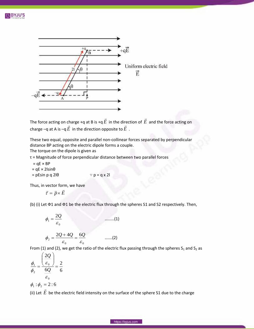
(b) (i) Let Ф1 and Ф1 be the electric flux through the spheres S1 and S2 respectively. Then,
0
1
2
Q ………(1)
00
2
642
QQQ
…….(2)
From (1) and (2), we get the ratio of the electric flux passing through the spheres S1 and S2 as
6:2:
6
2
6
2
21
0
0
2
1
Q
Q
(ii) Let E
be the electric field intensity on the surface of the sphere S1 due to the charge

2Q present inside the sphere. Then, according to Gauss’ theorem, we have
0
1
2.
QsdE
On introducing a medium of dielectric constant εr inside the sphere S1, suppose that
electric field becomes E
' . Then, we have
r
EE
' ’
The electric flux through the sphere is now Φ1’, then we have
0
1
2.
1.'
rr
QsdEsdE
Thus if a medium of dielectric constant εr is introduced in the space S1 instead of air the electric flux
through the sphere S1 becomes .2
0 r
Q