Embed Size (px)
Citation preview
www.Hyperion-World.com
CC3D Revolution Setup 1
CC3D Revolution Board Setup
Introduction
Welcome to the Revolution ( Revo ) board setup page. Along with the tutorials you will also
find links to the relevant Wiki pages to assist you in setting up the best Flight Controller
board on the market.
The OpenPilot Revolution board, also called ‘Revo’, is a new breed of Autopilot using the
STM32F4 series, 210MIPS ARM Micro-controller. This is important, as it contains a hardware
floating point unit (FPU), which is a huge advancement for the hobby-class autopilots. Of
course, OpenPilot has been 32bit since day one, and the FPU is another step up the
performance ladder. The FPU allows precise, low-latency processing of real-life measurements
using advanced attitude estimation algorithms.
The Revolution is a flight control computer with autopilot, intended for multirotors, helicopters
and fixed wings. It is a full 10DOF with gyroscope, accelerometer, magnetometer and
pressure sensors.
www.Hyperion-World.com
CC3D Revolution Setup 2
Setting up your Revolution Board for the first time
You have just received a brand new Revolution board and are itching to mount it in your air
frame, follow the instructions below.
Vehicle Setup Wizard
Once you have mounted your Revo on your frame you need to configure it through the
Ground Control Station (GCS) using the Vehicle Setup Wizard, follow the Tutorial below for
setting up on a Multirotor.
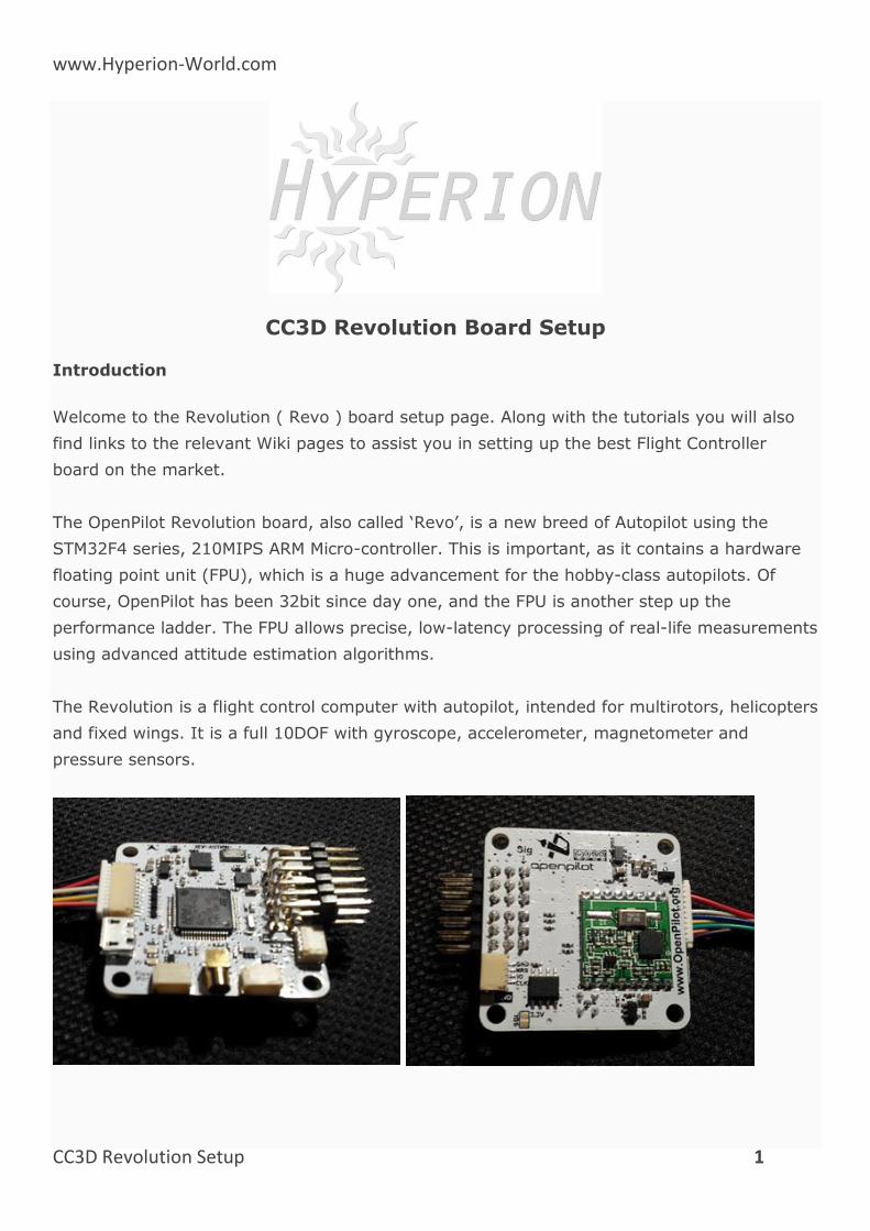
Connection diagram
The diagram below summarizes how the overall Revolution system is connected.
Technical description
CPU
CPU is the STM32F405RGT6 chip, with ARM Cortex-M4 core at 210MIPS, FPU, and saturation
arithmetic’s DSP functions.
The chip features a range of built-in hardware modules that can be programmed once and
function independently, requiring little to no CPU overhead. These include 14x multichannel
timers, 3x synchronous-sampling ADC serving up to 24 channels, 2x DAC, matrix memory
controller with 16-stream DMA, and other. Communication modules include USB2.0, 3x I2C,
3x SPI, 4x USART, 2x CAN and SIDO. All these modules can be configured for accessing the
chip pins using a flexible switch matrix, or disabled to save power.
www.Hyperion-World.com
CC3D Revolution Setup 3
It even contains a real time hardware calendar if you want a wake up flight. The software and
settings are loaded through USB connector and no-hassle update function in the GCS (Ground
Control Station).
Modem
The board features built-in 433MHz OPLink Modem.
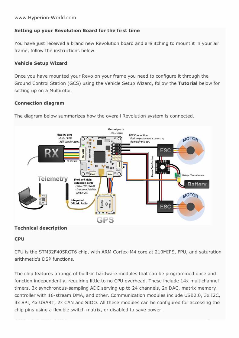
Dimensions
OpenPilot products use the standard OpenPilot footprint, and hence has the same dimensions
and mounting holes as the OpenPilot Revo, GPS, OSD and PipX boards.
(All dimensions are in millimeters.)
www.Hyperion-World.com
CC3D Revolution Setup 4
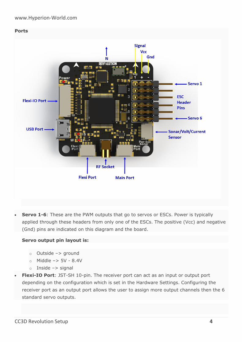
Ports
Servo 1-6: These are the PWM outputs that go to servos or ESCs. Power is typically
applied through these headers from only one of the ESCs. The positive (Vcc) and negative
(Gnd) pins are indicated on this diagram and the board.
Servo output pin layout is:
o Outside –> ground
o Middle –> 5V - 8.4V
o Inside –> signal
Flexi-IO Port: JST-SH 10-pin. The receiver port can act as an input or output port
depending on the configuration which is set in the Hardware Settings. Configuring the
receiver port as an output port allows the user to assign more output channels then the 6
standard servo outputs.
www.Hyperion-World.com
CC3D Revolution Setup 5
PWM -vs- PPM Receivers
Please be aware that not all receivers can be configured to use a PPM output. It is the
user’s responsibility to research this feature in regards to the desired receiver they wish to
use for PPM and ensure it can be used as such. Many hours of frustration can occur while
trying to troubleshoot why you can’t get your radio to connect to the board with PPM if
using a receiver that isn’t designed with that feature! Simply make sure the receiver can
do it before trying to set it up that way.
Main Port: JST-SH 4-pin. This is a serial USART whose baud rate can be adjusted through
the GCS. Optionally, Futaba S. Bus receiver, Spektrum/JR satellite receiver or GPS can be
mapped to the Main Port. Default configuration is Telemetry for connecting an RF modem.
Flexi Port: JST-SH 4-pin. The function of this port also depends on the configuration and
can be configured for I2C or Serial. The default configuration doesn’t use this port, but it
can be used for Telemetry, GPS, Spektrum satellite receivers (all working), and other I2C
peripherals (under development).
RF Socket: Antenna connection socket for on-board OPLink Modem.
Pwr Sen/Sonar Port: JST-SH 4-pin. This port can be configured to accommodate an
Autopilot current sensor and a low cost Sonar sensor such as the HC-SR04. It can also be
used as a general purpose input/output port or as a one or two channel analog input port.
Note
Please note that the output rate on the output channels from the Receiver Port cannot be set individually. If servos are connected to this outputs, you must ensure that they can work with
the defined output rate for choose a high output rate to support an octocopter configuration, the update rate from the output channels from the Receiver Port are bound to the update rate
from channels 5 & 6. In this case, you cannot connect analog servos to these outputs since an analog servo only supports an output rate of 50Hz.
Sensor suite
3 Axis Gyro
3 Axis Accelerometer
3 Axis Magnetometer
Barometric pressure sensor
www.Hyperion-World.com
CC3D Revolution Setup 6
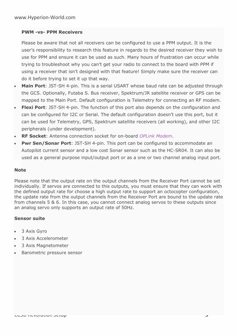
MPU
The MPU-6000 combines a 3-axis gyroscope and a 3-axis accelerometer on the same silicon
die. This sensor can also be found on the CC3D and already has a proven track record of
great flight performance.
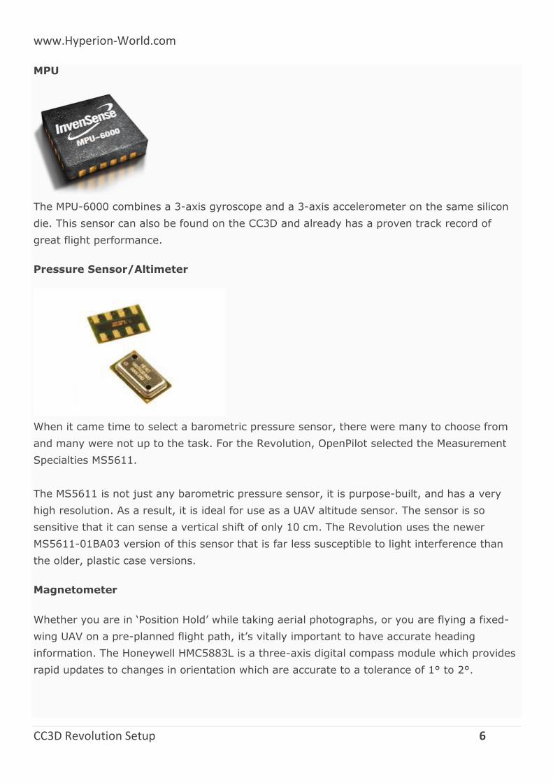
Pressure Sensor/Altimeter
When it came time to select a barometric pressure sensor, there were many to choose from
and many were not up to the task. For the Revolution, OpenPilot selected the Measurement
Specialties MS5611.
The MS5611 is not just any barometric pressure sensor, it is purpose-built, and has a very
high resolution. As a result, it is ideal for use as a UAV altitude sensor. The sensor is so
sensitive that it can sense a vertical shift of only 10 cm. The Revolution uses the newer
MS5611-01BA03 version of this sensor that is far less susceptible to light interference than
the older, plastic case versions.
Magnetometer
Whether you are in ‘Position Hold’ while taking aerial photographs, or you are flying a fixed-
wing UAV on a pre-planned flight path, it’s vitally important to have accurate heading
information. The Honeywell HMC5883L is a three-axis digital compass module which provides
rapid updates to changes in orientation which are accurate to a tolerance of 1° to 2°.
www.Hyperion-World.com
CC3D Revolution Setup 7
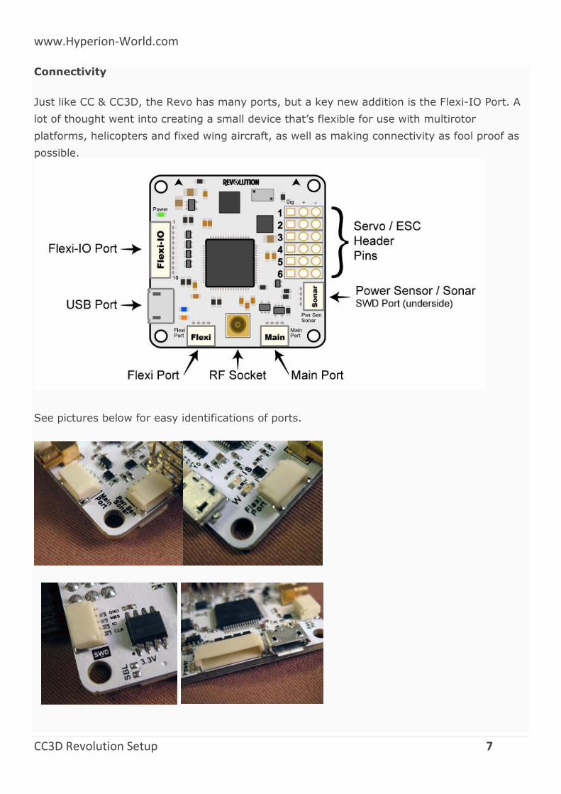
Connectivity
Just like CC & CC3D, the Revo has many ports, but a key new addition is the Flexi-IO Port. A
lot of thought went into creating a small device that’s flexible for use with multirotor
platforms, helicopters and fixed wing aircraft, as well as making connectivity as fool proof as
possible.
See pictures below for easy identifications of ports.
www.Hyperion-World.com
CC3D Revolution Setup 8
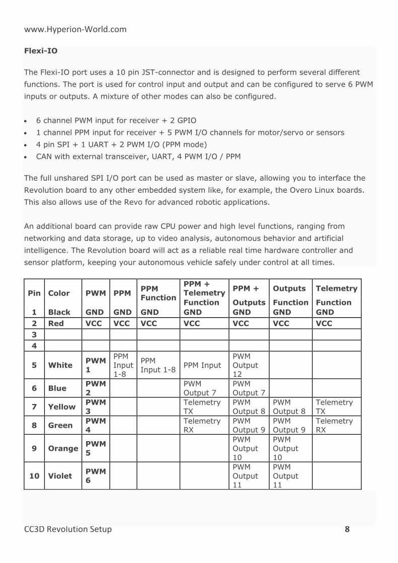
Flexi-IO
The Flexi-IO port uses a 10 pin JST-connector and is designed to perform several different
functions. The port is used for control input and output and can be configured to serve 6 PWM
inputs or outputs. A mixture of other modes can also be configured.
6 channel PWM input for receiver + 2 GPIO
1 channel PPM input for receiver + 5 PWM I/O channels for motor/servo or sensors
4 pin SPI + 1 UART + 2 PWM I/O (PPM mode)
CAN with external transceiver, UART, 4 PWM I/O / PPM
The full unshared SPI I/O port can be used as master or slave, allowing you to interface the
Revolution board to any other embedded system like, for example, the Overo Linux boards.
This also allows use of the Revo for advanced robotic applications.
An additional board can provide raw CPU power and high level functions, ranging from
networking and data storage, up to video analysis, autonomous behavior and artificial
intelligence. The Revolution board will act as a reliable real time hardware controller and
sensor platform, keeping your autonomous vehicle safely under control at all times.
Pin Color PWM PPM PPM Function
PPM + Telemetry
PPM + Outputs Telemetry
Function Outputs Function Function
1 Black GND GND GND GND GND GND GND
2 Red VCC VCC VCC VCC VCC VCC VCC
3
4
5 White PWM
1
PPM Input
1-8
PPM
Input 1-8 PPM Input
PWM Output
12
6 Blue PWM
2
PWM
Output 7
PWM
Output 7
7 Yellow PWM
3
Telemetry
TX
PWM
Output 8
PWM
Output 8
Telemetry
TX
8 Green PWM 4
Telemetry RX
PWM Output 9
PWM Output 9
Telemetry RX
9 Orange PWM
5
PWM Output
10
PWM Output
10
10 Violet PWM 6
PWM
Output 11
PWM
Output 11
www.Hyperion-World.com
CC3D Revolution Setup 9
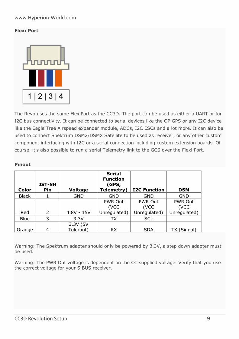
Flexi Port
The Revo uses the same FlexiPort as the CC3D. The port can be used as either a UART or for
I2C bus connectivity. It can be connected to serial devices like the OP GPS or any I2C device
like the Eagle Tree Airspeed expander module, ADCs, I2C ESCs and a lot more. It can also be
used to connect Spektrum DSM2/DSMX Satellite to be used as receiver, or any other custom
component interfacing with I2C or a serial connection including custom extension boards. Of
course, it’s also possible to run a serial Telemetry link to the GCS over the Flexi Port.
Pinout
Color JST-SH
Pin Voltage
Serial Function
(GPS, Telemetry) I2C Function DSM
Black 1 GND GND GND GND
Red 2 4.8V - 15V
PWR Out (VCC
Unregulated)
PWR Out (VCC
Unregulated)
PWR Out (VCC
Unregulated)
Blue 3 3.3V TX SCL
Orange 4
3.3V (5V
Tolerant) RX SDA TX (Signal)
Warning: The Spektrum adapter should only be powered by 3.3V, a step down adapter must
be used.
Warning: The PWR Out voltage is dependent on the CC supplied voltage. Verify that you use the correct voltage for your S.BUS receiver.
www.Hyperion-World.com
CC3D Revolution Setup 10
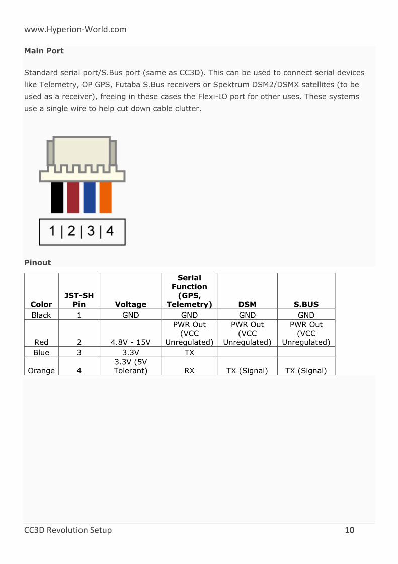
Main Port
Standard serial port/S.Bus port (same as CC3D). This can be used to connect serial devices
like Telemetry, OP GPS, Futaba S.Bus receivers or Spektrum DSM2/DSMX satellites (to be
used as a receiver), freeing in these cases the Flexi-IO port for other uses. These systems
use a single wire to help cut down cable clutter.
Pinout
Color JST-SH
Pin Voltage
Serial
Function (GPS,
Telemetry) DSM S.BUS
Black 1 GND GND GND GND
Red 2 4.8V - 15V
PWR Out
(VCC Unregulated)
PWR Out
(VCC Unregulated)
PWR Out
(VCC Unregulated)
Blue 3 3.3V TX
Orange 4 3.3V (5V Tolerant) RX TX (Signal) TX (Signal)
www.Hyperion-World.com
CC3D Revolution Setup 11
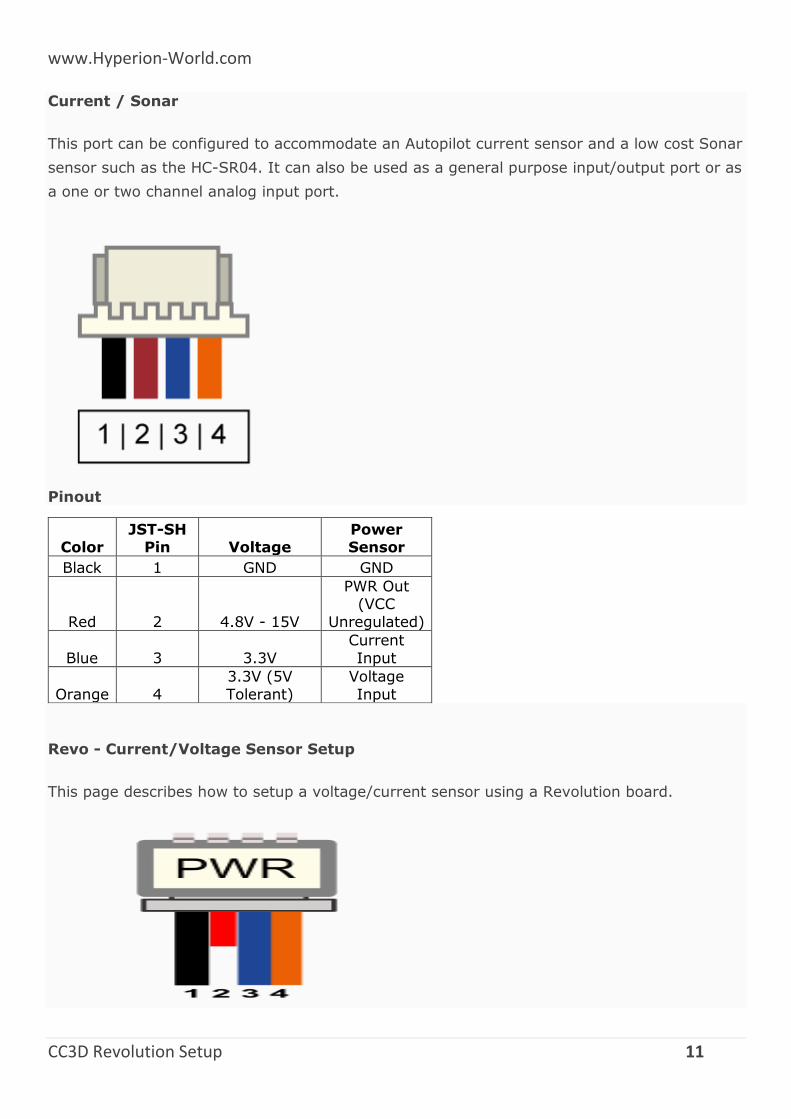
Current / Sonar
This port can be configured to accommodate an Autopilot current sensor and a low cost Sonar
sensor such as the HC-SR04. It can also be used as a general purpose input/output port or as
a one or two channel analog input port.
Pinout
Color JST-SH
Pin Voltage Power Sensor
Black 1 GND GND
Red 2 4.8V - 15V
PWR Out (VCC
Unregulated)
Blue 3 3.3V
Current
Input
Orange 4
3.3V (5V
Tolerant)
Voltage
Input
Revo - Current/Voltage Sensor Setup
This page describes how to setup a voltage/current sensor using a Revolution board.
www.Hyperion-World.com
CC3D Revolution Setup 12
Color
Connector pin
(board) Description
AttoPilot pin
(sensor)
Black 1 GND GND
Red 2 Vcc Not used
Blue 3 Current input I
Orange 4 Voltage input V
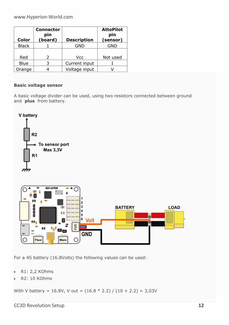
Basic voltage sensor
A basic voltage divider can be used, using two resistors connected between ground and plus from battery.
For a 4S battery (16.8Volts) the following values can be used:
R1: 2,2 KOhms
R2: 10 KOhms
With V battery = 16.8V, V out = (16.8 * 2.2) / (10 + 2.2) = 3,03V
www.Hyperion-World.com
CC3D Revolution Setup 13
See also http://en.wikipedia.org/wiki/Voltage_divider
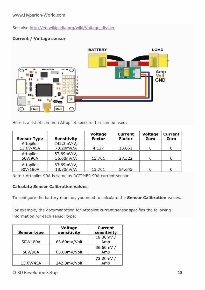
Current / Voltage sensor
Here is a list of common Attopilot sensors that can be used:
Sensor Type Sensitivity Voltage Factor
Current Factor
Voltage Zero
Current Zero
Attopilot 13.6V/45A
242.3mV/V, 73.20mV/A 4.127 13.661 0 0
Attopilot 50V/90A
63.69mV/V, 36.60mV/A 15.701 27.322 0 0
Attopilot
50V/180A
63.69mV/V,
18.30mV/A 15.701 54.645 0 0
Note : Attopilot 90A is same as RCTIMER 90A current sensor
Calculate Sensor Calibration values
To configure the battery monitor, you need to calculate the Sensor Calibration values.
For example, the documentation for Attopilot current sensor specifies the following
information for each sensor type:
Sensor type
Voltage
sensitivity
Current
sensitivity
50V/180A 63.69mV/Volt
18.30mV /
Amp
50V/90A 63.69mV/Volt
36.60mV /
Amp
13.6V/45A 242.3mV/Volt 73.20mV /
Amp
www.Hyperion-World.com
CC3D Revolution Setup 14
In order to use 50V/90A you’ll have to do the following:
Convert everything to Volt, so Volt/Volt and Volt/Amp:
o 63.69mV/V / 1000 = 0.06369 V/V
o 36.60mV/A / 1000 = 0.0366 V/A
Then calculate the values to insert in Voltage and Current Factors:
o VoltageFactor = 1 / 0.06369 = 15.701
o CurrentFactor = 1 / 0.0366 = 27.322
Those factors are start values that can be adjusted later from readings, generally sensor’s
sensitivity are not so accurate.
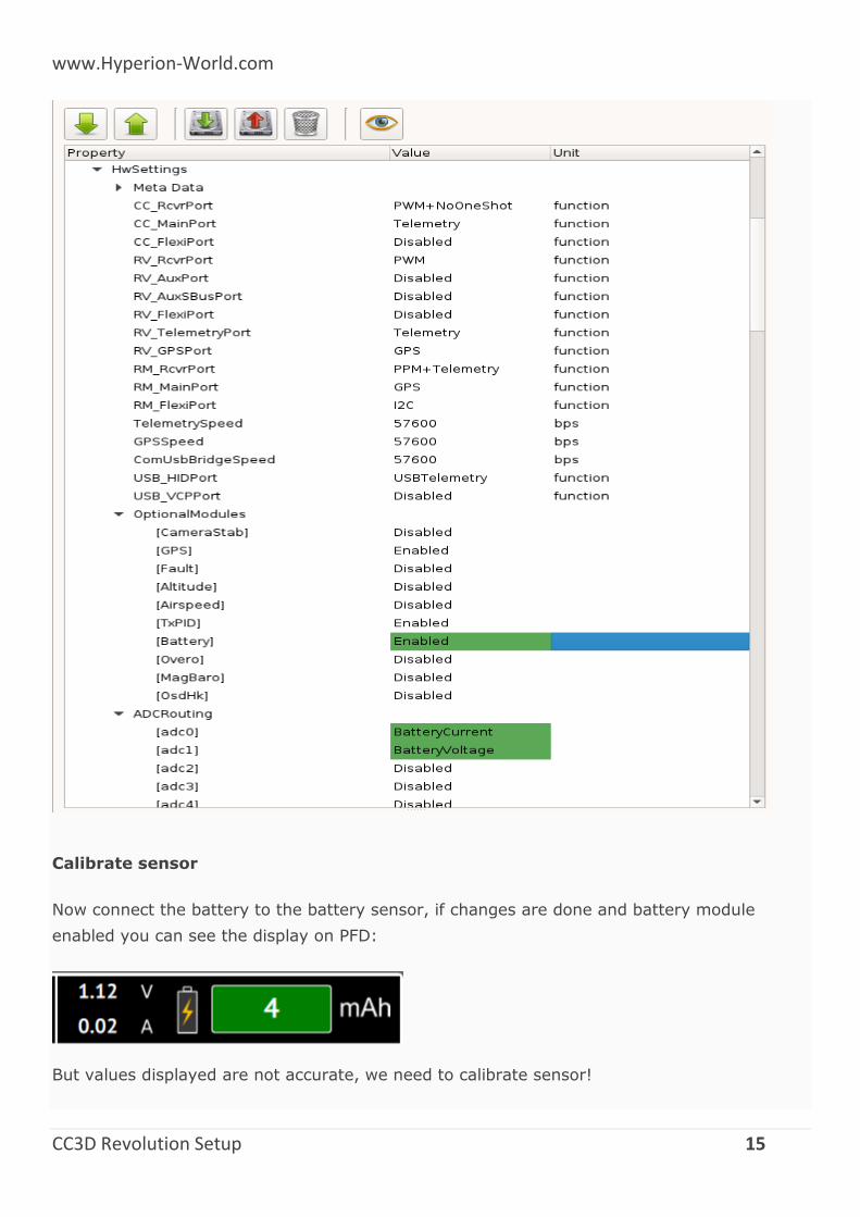
Hardware settings
The first thing to do is to configure the hardware settings:
1. Connect the board to your computer and got to the System tab in your GCS
2. Browse the first part (Settings) and find the HwSettings UAVObject
3. Enable the Battery module: Optional Modules > Battery > Enable
4. Set the analog input pins for voltage and current:
ADCRouting > adc0 > BatteryCurrent
ADCRouting > adc1 > BatteryVoltage
5. Save changes, click Upload button
6. Reboot your board: disconnect all power sources and reconnect to your computer.
www.Hyperion-World.com
CC3D Revolution Setup 15
Calibrate sensor
Now connect the battery to the battery sensor, if changes are done and battery module
enabled you can see the display on PFD:
But values displayed are not accurate, we need to calibrate sensor!
www.Hyperion-World.com
CC3D Revolution Setup 16
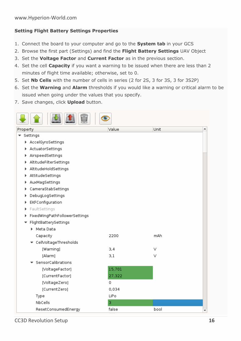
Setting Flight Battery Settings Properties
1. Connect the board to your computer and go to the System tab in your GCS
2. Browse the first part (Settings) and find the Flight Battery Settings UAV Object
3. Set the Voltage Factor and Current Factor as in the previous section.
4. Set the cell Capacity if you want a warning to be issued when there are less than 2
minutes of flight time available; otherwise, set to 0.
5. Set Nb Cells with the number of cells in series (2 for 2S, 3 for 3S, 3 for 3S2P)
6. Set the Warning and Alarm thresholds if you would like a warning or critical alarm to be
issued when going under the values that you specify.
7. Save changes, click Upload button.
www.Hyperion-World.com
CC3D Revolution Setup 17
Note :
Sometimes sensor are not accurate with small readings, especially for current.
A Current Zero setting can be set without any load change this value to obtain a 0 ampers display.
PWM output headers
Just like the CC & CC3D, the Revo has a bank of 6 PWM output headers. If more PWM outputs
are needed - the Flexi-IO port can be configured to support up to an additional 6 PWM
channels if so required. PWM port 5 can also be configured to communicate with an external
analog airspeed sensor or a governor for helicopters.
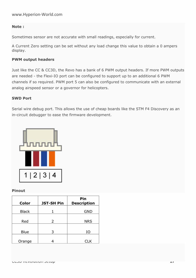
SWD Port
Serial wire debug port. This allows the use of cheap boards like the STM F4 Discovery as an
in-circuit debugger to ease the firmware development.
Pinout
Color JST-SH Pin
Pin
Description
Black 1 GND
Red 2 NRS
Blue 3 IO
Orange 4 CLK
www.Hyperion-World.com
CC3D Revolution Setup 18
Micro USB
We have decided to move away from using the mini USB port found on the existing CC and
CC3D and instead use a Micro USB port. The Micro USB port has several benefits, it’s
physically smaller, more robust, a much more widely adopted standard, and is the same type
of port found on the majority of mobile phones. In all likelihood, you’ll already have one of
these cables at home.
The USB port provides a USB composite device with the following functions:
OpenPilot HID device (default GCS interface, uses PC system drivers)
CDC virtual serial port (telemetry, debugging, serial bridge mode relaying data from/to
physical serial port to the virtual one for GPS/Bluetooth module setup, etc)
8-channel HID joystick (passes data from all supported R/C inputs to PC flight simulators)
OPLink Modem
The Revolution has its own OPLink Mini built right onto the board! This is not only a 10DoF
flight controller with an ST32F4 processor in the same small footprint as the CC3D, but also
has its own LRS modem. The modem is directly powered from the Revolution itself, so you
don’t need to worry about any additional power supply.
Of course, the on-board modem will have the same functionality as the OPLink Mini. Both are
fully configurable from the GCS.
Operating on the 433MHz band (a 900Mhz version will be released at a later date), the
modem provides a direct telemetry link between the GCS and your flight controller. And just
as with the OPLink Mini, you can adjust the output RF power for compliance with any
governmental RF regulations, or it can be disabled entirely.
DIY Board Users
Please download below file for Schematics, PCB Layout.
http://opwiki.readthedocs.io/en/latest/_downloads/Revolution.zip
www.Hyperion-World.com
CC3D Revolution Setup 19
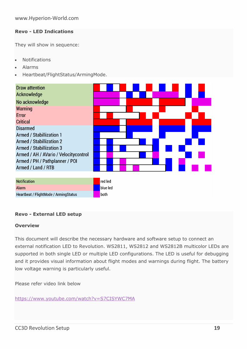
Revo - LED Indications
They will show in sequence:
Notifications
Alarms
Heartbeat/FlightStatus/ArmingMode.
Revo - External LED setup
Overview
This document will describe the necessary hardware and software setup to connect an
external notification LED to Revolution. WS2811, WS2812 and WS2812B multicolor LEDs are
supported in both single LED or multiple LED configurations. The LED is useful for debugging
and it provides visual information about flight modes and warnings during flight. The battery
low voltage warning is particularly useful.
Please refer video link below
https://www.youtube.com/watch?v=S7CISYWC7MA
www.Hyperion-World.com
CC3D Revolution Setup 20
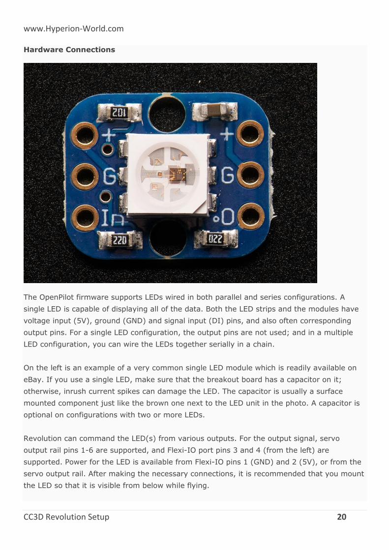
Hardware Connections
The OpenPilot firmware supports LEDs wired in both parallel and series configurations. A
single LED is capable of displaying all of the data. Both the LED strips and the modules have
voltage input (5V), ground (GND) and signal input (DI) pins, and also often corresponding
output pins. For a single LED configuration, the output pins are not used; and in a multiple
LED configuration, you can wire the LEDs together serially in a chain.
On the left is an example of a very common single LED module which is readily available on
eBay. If you use a single LED, make sure that the breakout board has a capacitor on it;
otherwise, inrush current spikes can damage the LED. The capacitor is usually a surface
mounted component just like the brown one next to the LED unit in the photo. A capacitor is
optional on configurations with two or more LEDs.
Revolution can command the LED(s) from various outputs. For the output signal, servo
output rail pins 1-6 are supported, and Flexi-IO port pins 3 and 4 (from the left) are
supported. Power for the LED is available from Flexi-IO pins 1 (GND) and 2 (5V), or from the
servo output rail. After making the necessary connections, it is recommended that you mount
the LED so that it is visible from below while flying.
www.Hyperion-World.com
CC3D Revolution Setup 21
Software Setup
Following hardware setup, configure the controller in GCS as follows:
Go to System tab > HwSettings > WS2811LED_Out and choose the pin where you
connected the LED(s)
Click the red Save button in the top part of the view
Disconnect Revolution from PC
Connect your flight battery. LED(s) should start showing system status according to the
graphic in the Light Codes section below.
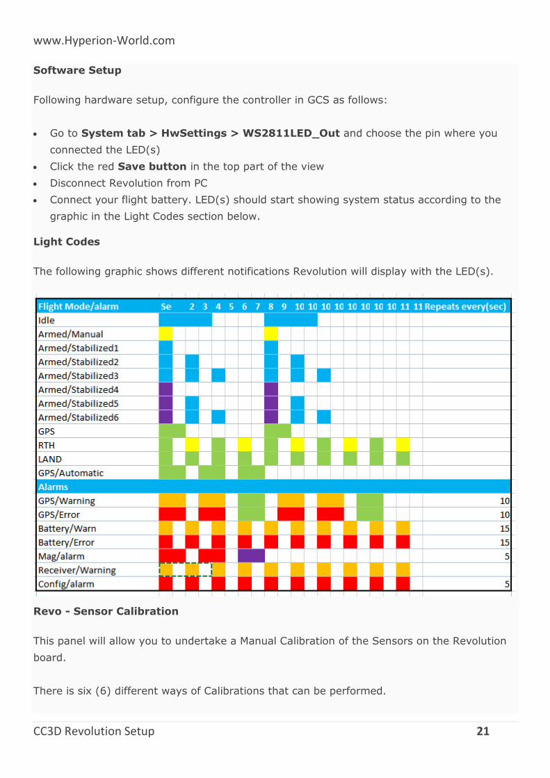
Light Codes
The following graphic shows different notifications Revolution will display with the LED(s).
Revo - Sensor Calibration
This panel will allow you to undertake a Manual Calibration of the Sensors on the Revolution
board.
There is six (6) different ways of Calibrations that can be performed.
www.Hyperion-World.com
CC3D Revolution Setup 22
Setting Home Location
Thermal Calibration
Accelerometer Bias Calibration
Magnetometer Calibration
Board Level Calibration
Gyro Bias Calibration
How to video link below.
https://www.youtube.com/watch?v=dn9IDw2D1qw
Setting Home Location
Warning
You must set your home location before performing the Sensor Calibrations
There is two ways of setting your home location:
1. Using GPS Module
2. Manually Select
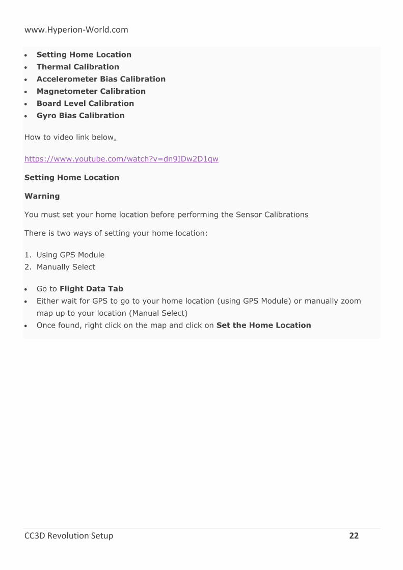
Go to Flight Data Tab
Either wait for GPS to go to your home location (using GPS Module) or manually zoom
map up to your location (Manual Select)
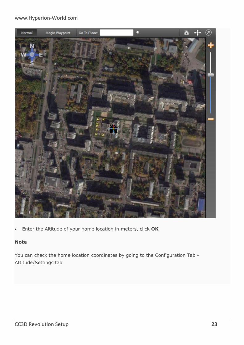
Once found, right click on the map and click on Set the Home Location
www.Hyperion-World.com
CC3D Revolution Setup 23
Enter the Altitude of your home location in meters, click OK
Note
You can check the home location coordinates by going to the Configuration Tab -
Attitude/Settings tab

www.Hyperion-World.com
CC3D Revolution Setup 24
Thermal Calibration
Note
The procedure below outlines the way to thermally calibrate the Revo to meet large
temperature changes, it is not essential to put in the freezer as the min and max temp ranges of the calibration only need to be below and above the ambit temps of your location. (approx +- 10/15 deg C above and below)
However if the temperature rises or falls above or below the min/max temps you calibrated
at, you will need to redo this calibration, so it is best to use some form of cooling to lower the min start temp and raise above max ambit temps of your location.
Also note this calibration is not needed, but will improve the performance of your board
1. Plug your USB cable into your Revo. Start the OP GCS and ensure that you have disabled
the OPLink modem (i.e. Max Power = 0). Then Save and Disconnect. Remove USB
cable from computer but leave Revo plugged in.
2. Put your Revo in a plastic bag and seal it reasonably well, but with the USB cable exiting
the baggie so it can be plugged in the computer.
Note
The bag is because we are going to freeze Revo and it will get condensation on it if we don’t
do this. For added temperature range (higher temperatures) you might build a very simple
hot box out of a low wattage incandescent light and a shoe box. You also might consider just
www.Hyperion-World.com
CC3D Revolution Setup 25
wrapping Revo up in a good insulator, like a warm lightweight modern jacket. You could also
set it out in the hot sun in the summer if you can plug it into USB at the same time.
3. Put Revo/baggie/cable in the freezer for 20 minutes or so.
4. Take it out, put it in the hot box or wrapped up or in the sun, or not... Immediately start
the thermal calibration.
Don’t move it at all while calibrating this test (gyros and baro are being calibrated).
Don’t allow your home heater or air conditioner fan to run while doing this test. (air
pressure changes).
Don’t open or close any doors in the house. (air pressure changes).
Don’t do this on a windy day (chimney, etc.).
Don’t do this on a stormy day (rapid changes in barometer).
Don’t play 1812 Overture or let your sister dance in the next room.
5. Watch the thermal calibration and unplug the light bulb when it gets within a few degrees
of your desired high temperature (i.e. 10-15 deg above what hottest day in your location).
6. If it finishes thermal calibration before reaching your desired temperature, you can start
over or use what you have.
7. Save your thermal calibration with the Save button in the lower right.
Note
You can check the temperature min-max (temp_calibrated_extent). Go to the System Tab
then Settings/Accel Gyro Settings/temp_calibrated_extent. You can then see the min & max
calibrated temps (below is screen shot of uncalibrated board showing 0 for both min & max,
once calibrated you will see your boards min & max temps)
Accelerometer Calibration
Warning
During this calibration the board MUST remain perfectly still during each position of
calibration. Even vibrations on a table or someone walking past could upset the calibration
On the Calibration Tab, click start “Accelerometer calibration”.
1. Place the board as shown in the picture on screen and click Save Position.
www.Hyperion-World.com
CC3D Revolution Setup 26
2. If the calibration failed, you will need to restart the accelerometer calibration over.
Multirotor Vehicle Setup Wizard
The Vehicle Setup Wizard allows users to step through and setup all the initial settings
including the TX.
When the GCS is started, the Vehicle Setup Wizard can be accessed by clicking on the
“green” Vehicle Setup Wizard button.
Ensure board is connected through USB port before starting Wizard.
Depending on the flight controller board, some screens may or may not be displayed as you
progress through the wizard.
First Flight
Pre-flight checks.
There are a few things that you’ll want to check before flying. Especially in the case of a
multi-rotor. If you have swapped your motor outputs or your servo output is reversed, then
the multi-rotor may flip or spin directly upon lift off.
Warning
REMOVE PROPELLERS!
You should always remove your propellers prior to starting tests or connecting your
battery for the first time.
Arming (Turn your board on)
At start-up the system is disarmed. When disarmed, the motor(s) will not function, but the
servos should work (If installed, e.g. on Tri-Copter). Before flying, the system needs to be
armed with a specific stick input. The input that is needed for arming (and disarming) is
configurable. For safety reasons, the default configuration is such that the system will not
arm under any condition. Hence, it’s mandatory that you configure the arming in the GCS
input configuration.
Check your system alarms
The flight controller will not arm itself if any system status alarms are present. They can be
checked by connecting to the flight controller board with OpenPilot Ground Control Station,
www.Hyperion-World.com
CC3D Revolution Setup 27
and looking at system status indication under the primary flight display. All status objects
should be green. PATH can remain yellow. For more information on alarms, read the next
page.
Check your stick inputs
With props removed, after you have armed your board, the blue LED should start flashing
rapidly indicating that the board is armed. If you have specified that the “motors should spin
at neutral output” in the output configuration, the motors should start spinning right now.
Otherwise you can now apply some throttle and get the motors spinning.
Verify that the correct motors follow your stick input. E.g. rolling left should increase the
throttle on your right motor(s) and vice versa. If the wrong motors are spinning faster, you
need to recheck your configuration.
Rate mode
Note that some motors could start spinning faster if you have already selected a stability
mode on your transmitter with the Flight Mode switch. You should do your first tests in rate
mode only.
Check your stabilization
While the motors are spinning, you can move the aircraft in the pitch or roll direction. The
flight controller should react promptly and accelerate the correct motors to counteract the
movement. Please make sure that the correct motors are spinning up. If the opposite motors
spin up, then you would flip your multi-rotor immediately upon lift off. In this case, you need
to recheck your configuration.
Important: Check fail-safe!
Arm the aircraft and run your motors, now turn off the transmitter and confirm that all
motors stop.
Your first flight (multicopters and helicopters)
You’ve done your pre-flight checks, your transmitter and flight batteries are all fully charged,
and you are confident that the vehicle has been configured correctly - it’s time to fly!
But, it’s also time to take a deep breath and honestly evaluate your flying skills - if you are a
novice then you should consider buying a flight simulator and developing some basic skills -
www.Hyperion-World.com
CC3D Revolution Setup 28
crashes in a simulator cost nothing, so you will rapidly justify the investment for this
software.
If you are feeling confident, take the model to a large, clear and deserted open space - you
don’t want any trees or overhead wires nearby, you definitely don’t want any people or dogs
in the area, and you shouldn’t be too close to a road. A grass field is better for first flights,
rather than concrete or tarmac. Ideally there will be no wind, but a very slight breeze
shouldn’t be a problem.
Important
You may be disconnecting and connecting power to the model several times during these first
steps - you must wait at least 30 seconds before reconnecting power, otherwise the model
may behave unpredictably.
Remember to keep the model still for about 10 seconds after each connection, while the
gyros are calibrated.
The following steps have been written on the assumption that ‘Zero gyros while arming
aircraft’ has been selected on the Attitude Configuration page of GCS (the recommended
setting). This can help with the stabilization of the model.
Note
Remember to keep the model still for several seconds after arming, while the gyros are
zeroed.
1. If you have brought anybody with you to witness the first flight, make sure that they know
where to stand, how to behave, and what to do if the vehicle goes out of control. If there
are any children, make sure that they are under close supervision.
2. Put the throttle stick to minimum and switch on the transmitter. If your transmitter has a
throttle lock facility, set this to ‘locked’. Put the transmitter on the ground next to where
you plan to stand while flying the vehicle.
3. Place the model on the ground about 10 paces away with the tail towards the transmitter.
If there is a breeze, put the model either upwind or downwind of the transmitter - you
don’t want a cross-wind.
4. Connect the power to the vehicle and do not move it for about 10 seconds while the
gyros are calibrated. Return to your transmitter.
5. Take a good look around for safety’s sake, then unlock the throttle and arm your board -
the blue LED on the board will now flash rapidly and the rotors will spin if you’ve selected
www.Hyperion-World.com
CC3D Revolution Setup 29
‘Motors spin at neutral output when armed’. IMPORTANT: you must wait a few
seconds after arming while the gyros are zeroed (see note above). The aircraft may
be unstable if this isn’t done. Use this time to have another good look around you.
6. Steadily increase the throttle until the vehicle is about to lift off the ground - any tendency
to flip or spin will be apparent at this time. Close the throttle immediately if the vehicle
does anything unexpected, and then take a look at the problem-finding guide.
7. If everything looks OK. then close the throttle, disarm the vehicle, take a deep breath and
have yet another look round the field - it’s time for lift-off!
8. Arm the vehicle, wait for a few seconds, then open the throttle confidently until the
aircraft lifts off the ground. Try to hover about 1 or 2 meters off the ground, while keeping
in one position.
You are now flying! Obviously this bit is not as easy as it sounds and much practice is
required.
The important thing to remember is to close the throttle if the aircraft goes out of control -
you will crash at some time, and cutting the power will minimize the damage.
Get into the habit of disarming the board when landing for more than a few seconds or when
approaching the vehicle to handle it, and don’t forget the short wait after re-arming - again,
use this period to look around the field before flying.
Disarm the board and set the throttle lock when you have finished flying, then put down the
transmitter a little way from the model. Disconnect the power from the aircraft, then turn off
your transmitter.
Now that you have proven that the aircraft will fly, you might like to try the training exercise
videos for helicopters found on this website page. Many of these are also suitable for multi-
rotors.
Optimizing values
Apart from tuning the stabilization settings, there are some values which advanced users may
want to change pretty soon. The default values will fly your aircraft perfectly fine, but would
limit some users in their flying style.
Please find below a few settings which can easily be cranked up for more experienced users.
Note: these are available in each of the three Settings Banks.
www.Hyperion-World.com
CC3D Revolution Setup 30
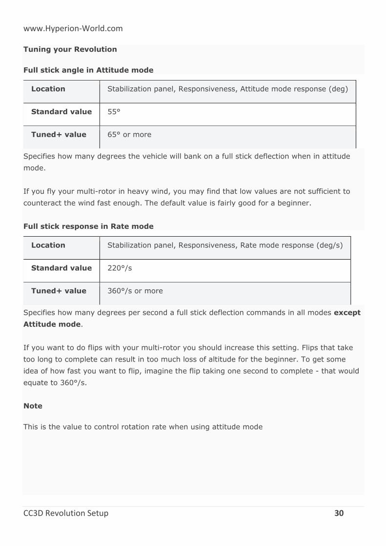
Tuning your Revolution
Full stick angle in Attitude mode
Location Stabilization panel, Responsiveness, Attitude mode response (deg)
Standard value 55°
Tuned+ value 65° or more
Specifies how many degrees the vehicle will bank on a full stick deflection when in attitude
mode.
If you fly your multi-rotor in heavy wind, you may find that low values are not sufficient to
counteract the wind fast enough. The default value is fairly good for a beginner.
Full stick response in Rate mode
Location Stabilization panel, Responsiveness, Rate mode response (deg/s)
Standard value 220°/s
Tuned+ value 360°/s or more
Specifies how many degrees per second a full stick deflection commands in all modes except
Attitude mode.
If you want to do flips with your multi-rotor you should increase this setting. Flips that take
too long to complete can result in too much loss of altitude for the beginner. To get some
idea of how fast you want to flip, imagine the flip taking one second to complete - that would
equate to 360°/s.
Note
This is the value to control rotation rate when using attitude mode
www.Hyperion-World.com
CC3D Revolution Setup 31
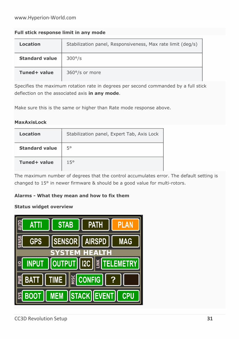
Full stick response limit in any mode
Location Stabilization panel, Responsiveness, Max rate limit (deg/s)
Standard value 300°/s
Tuned+ value 360°/s or more
Specifies the maximum rotation rate in degrees per second commanded by a full stick
deflection on the associated axis in any mode.
Make sure this is the same or higher than Rate mode response above.
MaxAxisLock
Location Stabilization panel, Expert Tab, Axis Lock
Standard value 5°
Tuned+ value 15°
The maximum number of degrees that the control accumulates error. The default setting is
changed to 15° in newer firmware & should be a good value for multi-rotors.
Alarms - What they mean and how to fix them
Status widget overview
www.Hyperion-World.com
CC3D Revolution Setup 32
The OpenPilot/LibrePilot flight control firmware has a built-in status system that gives you an
overview about what’s happening with the board. The System Health Status widget in the
Ground Control Station can be used to diagnose various problems, and to check which
modules of the firmware are running.
Arming
The flight control board cannot be armed until crossed-out alarms and red alarms have been
solved. All objects, except for the special “Plan”, should be green for optimal flight
performance. The information corresponds to the UAVObject DataObjects > SystemAlarms
> Alarm.
Status object explanations
Auto (Autonomous)
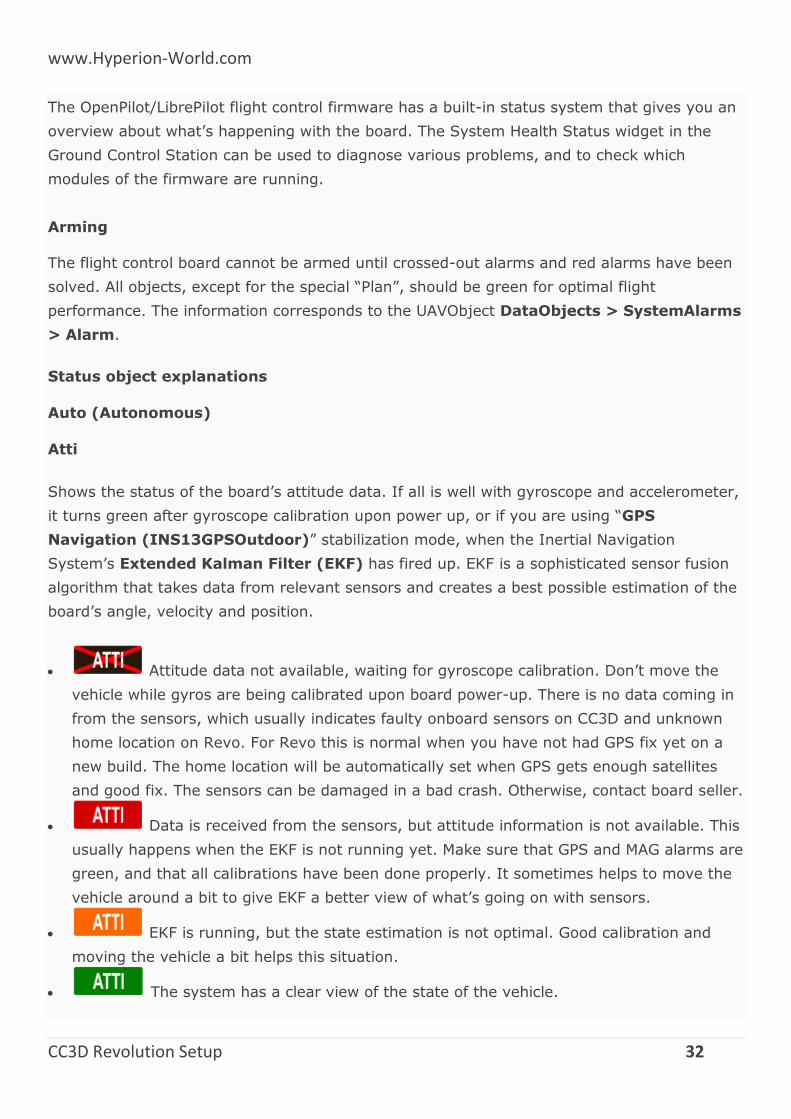
Atti
Shows the status of the board’s attitude data. If all is well with gyroscope and accelerometer,
it turns green after gyroscope calibration upon power up, or if you are using “GPS
Navigation (INS13GPSOutdoor)” stabilization mode, when the Inertial Navigation
System’s Extended Kalman Filter (EKF) has fired up. EKF is a sophisticated sensor fusion
algorithm that takes data from relevant sensors and creates a best possible estimation of the
board’s angle, velocity and position.
Attitude data not available, waiting for gyroscope calibration. Don’t move the
vehicle while gyros are being calibrated upon board power-up. There is no data coming in
from the sensors, which usually indicates faulty onboard sensors on CC3D and unknown
home location on Revo. For Revo this is normal when you have not had GPS fix yet on a
new build. The home location will be automatically set when GPS gets enough satellites
and good fix. The sensors can be damaged in a bad crash. Otherwise, contact board seller.
Data is received from the sensors, but attitude information is not available. This
usually happens when the EKF is not running yet. Make sure that GPS and MAG alarms are
green, and that all calibrations have been done properly. It sometimes helps to move the
vehicle around a bit to give EKF a better view of what’s going on with sensors.
EKF is running, but the state estimation is not optimal. Good calibration and
moving the vehicle a bit helps this situation.
The system has a clear view of the state of the vehicle.
www.Hyperion-World.com
CC3D Revolution Setup 33
“The Bug”
There is a very specific condition that can arise within the system that can sometimes occur
after the EKF has been initialized, and the vehicle has been left stationary for an extended
period of time. Fortunately, this condition is easily detected and the flight firmware mitigates
the event. However, the solution is extremely complicated and beyond the capability of most
people, and until such stage as the developers have a chance to address the matter, it’s
occurrence is indicated as follows:
A large red X appears over the PFD.
A Yellow ATTI alarm with STAB green
This event has been nicknamed “The Bug”, and it is still possible to arm and fly the vehicle in
this condition.
Should you wish to clear the indication, one can reset the Revolution flight controller, or
alternatively, change the Attitude Estimation Algorithm to Basic(Complementary), and
then change back to GPS Navigation(INS13). This action will cause the EKF to reinitialize
and the indications will be cleared.
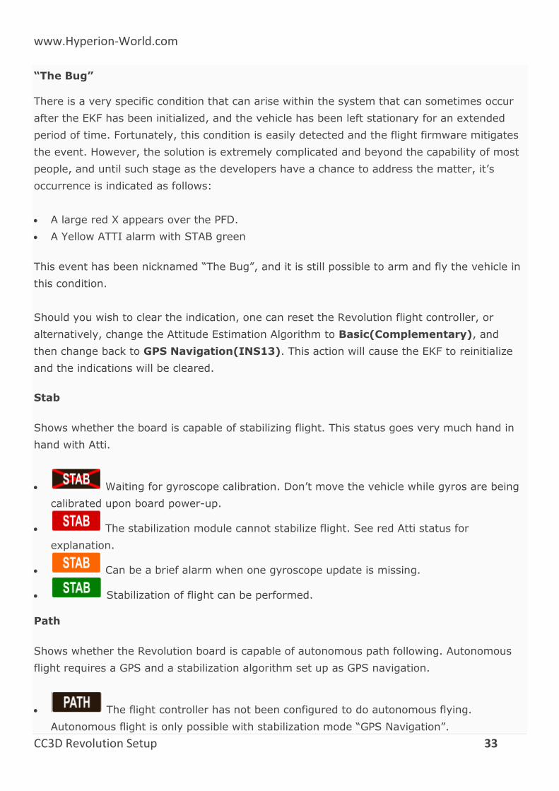
Stab
Shows whether the board is capable of stabilizing flight. This status goes very much hand in
hand with Atti.
Waiting for gyroscope calibration. Don’t move the vehicle while gyros are being
calibrated upon board power-up.
The stabilization module cannot stabilize flight. See red Atti status for
explanation.
Can be a brief alarm when one gyroscope update is missing.
Stabilization of flight can be performed.
Path
Shows whether the Revolution board is capable of autonomous path following. Autonomous
flight requires a GPS and a stabilization algorithm set up as GPS navigation.
The flight controller has not been configured to do autonomous flying.
Autonomous flight is only possible with stabilization mode “GPS Navigation”.
www.Hyperion-World.com
CC3D Revolution Setup 34
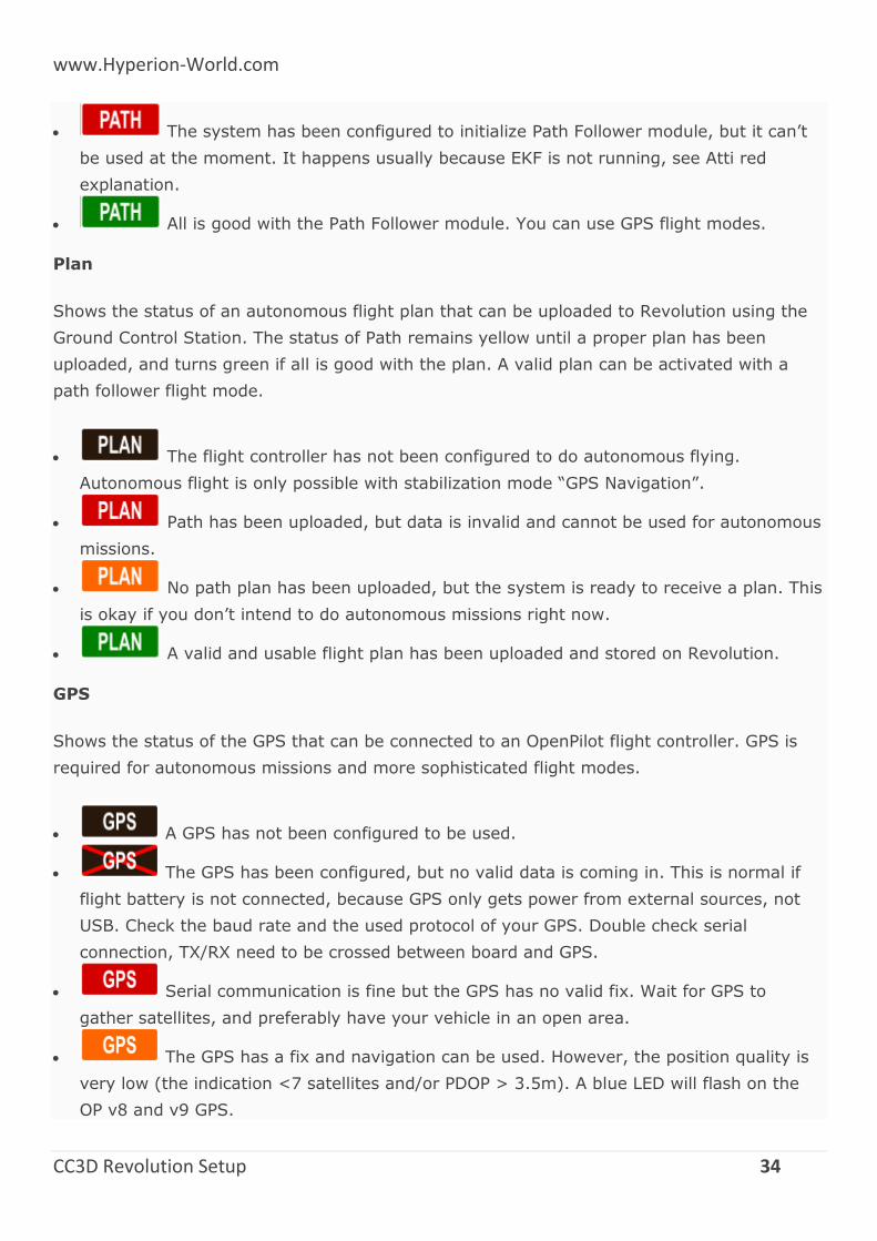
The system has been configured to initialize Path Follower module, but it can’t
be used at the moment. It happens usually because EKF is not running, see Atti red
explanation.
All is good with the Path Follower module. You can use GPS flight modes.
Plan
Shows the status of an autonomous flight plan that can be uploaded to Revolution using the
Ground Control Station. The status of Path remains yellow until a proper plan has been
uploaded, and turns green if all is good with the plan. A valid plan can be activated with a
path follower flight mode.
The flight controller has not been configured to do autonomous flying.
Autonomous flight is only possible with stabilization mode “GPS Navigation”.
Path has been uploaded, but data is invalid and cannot be used for autonomous
missions.
No path plan has been uploaded, but the system is ready to receive a plan. This
is okay if you don’t intend to do autonomous missions right now.
A valid and usable flight plan has been uploaded and stored on Revolution.
GPS
Shows the status of the GPS that can be connected to an OpenPilot flight controller. GPS is
required for autonomous missions and more sophisticated flight modes.
A GPS has not been configured to be used.
The GPS has been configured, but no valid data is coming in. This is normal if
flight battery is not connected, because GPS only gets power from external sources, not
USB. Check the baud rate and the used protocol of your GPS. Double check serial
connection, TX/RX need to be crossed between board and GPS.
Serial communication is fine but the GPS has no valid fix. Wait for GPS to
gather satellites, and preferably have your vehicle in an open area.
The GPS has a fix and navigation can be used. However, the position quality is
very low (the indication <7 satellites and/or PDOP > 3.5m). A blue LED will flash on the
OP v8 and v9 GPS.
www.Hyperion-World.com
CC3D Revolution Setup 35
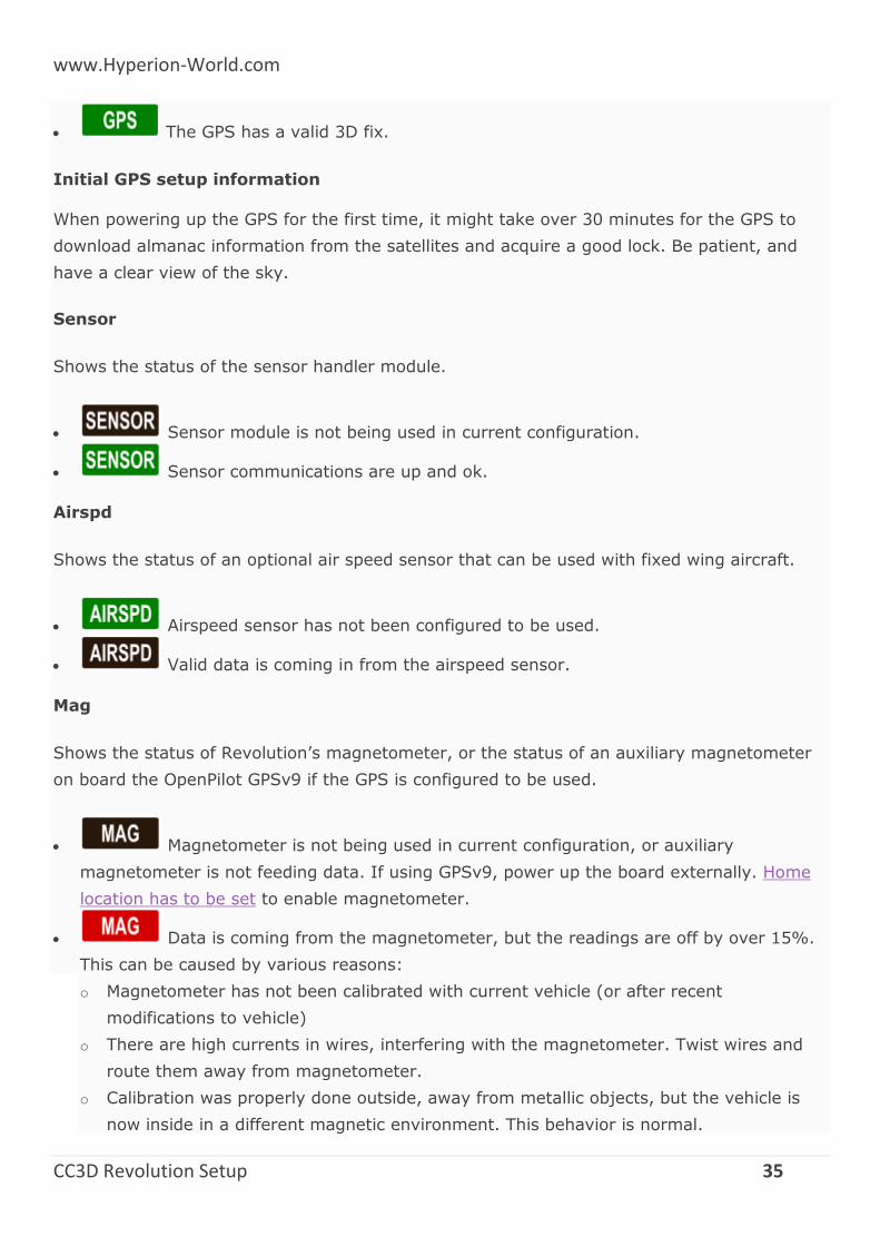
The GPS has a valid 3D fix.
Initial GPS setup information
When powering up the GPS for the first time, it might take over 30 minutes for the GPS to
download almanac information from the satellites and acquire a good lock. Be patient, and
have a clear view of the sky.
Sensor
Shows the status of the sensor handler module.
Sensor module is not being used in current configuration.
Sensor communications are up and ok.
Airspd
Shows the status of an optional air speed sensor that can be used with fixed wing aircraft.
Airspeed sensor has not been configured to be used.
Valid data is coming in from the airspeed sensor.
Mag
Shows the status of Revolution’s magnetometer, or the status of an auxiliary magnetometer
on board the OpenPilot GPSv9 if the GPS is configured to be used.
Magnetometer is not being used in current configuration, or auxiliary
magnetometer is not feeding data. If using GPSv9, power up the board externally. Home
location has to be set to enable magnetometer.
Data is coming from the magnetometer, but the readings are off by over 15%.
This can be caused by various reasons:
o Magnetometer has not been calibrated with current vehicle (or after recent
modifications to vehicle)
o There are high currents in wires, interfering with the magnetometer. Twist wires and
route them away from magnetometer.
o Calibration was properly done outside, away from metallic objects, but the vehicle is
now inside in a different magnetic environment. This behavior is normal.
www.Hyperion-World.com
CC3D Revolution Setup 36
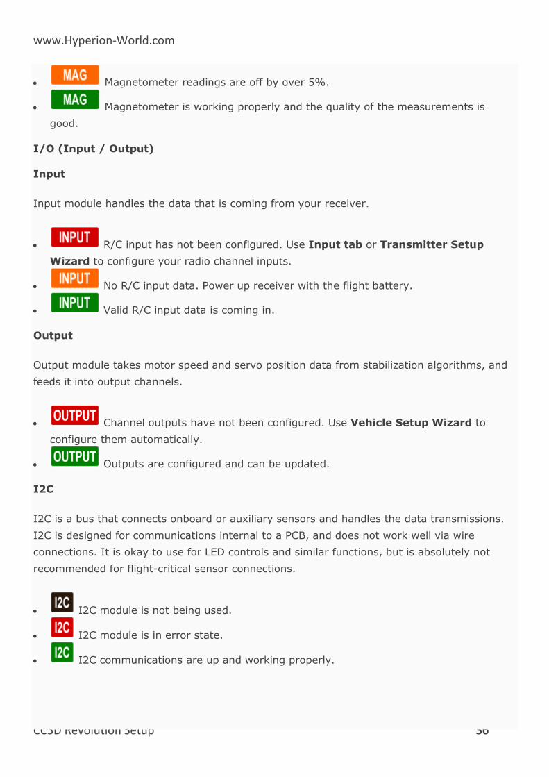
Magnetometer readings are off by over 5%.
Magnetometer is working properly and the quality of the measurements is
good.
I/O (Input / Output)
Input
Input module handles the data that is coming from your receiver.
R/C input has not been configured. Use Input tab or Transmitter Setup
Wizard to configure your radio channel inputs.
No R/C input data. Power up receiver with the flight battery.
Valid R/C input data is coming in.
Output
Output module takes motor speed and servo position data from stabilization algorithms, and
feeds it into output channels.
Channel outputs have not been configured. Use Vehicle Setup Wizard to
configure them automatically.
Outputs are configured and can be updated.
I2C
I2C is a bus that connects onboard or auxiliary sensors and handles the data transmissions.
I2C is designed for communications internal to a PCB, and does not work well via wire
connections. It is okay to use for LED controls and similar functions, but is absolutely not
recommended for flight-critical sensor connections.
I2C module is not being used.
I2C module is in error state.
I2C communications are up and working properly.
www.Hyperion-World.com
CC3D Revolution Setup 37
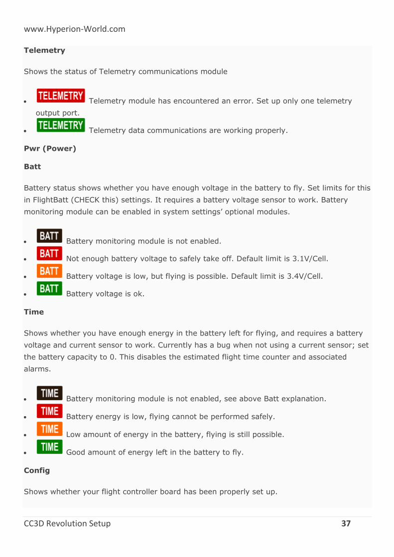
Telemetry
Shows the status of Telemetry communications module
Telemetry module has encountered an error. Set up only one telemetry
output port.
Telemetry data communications are working properly.
Pwr (Power)
Batt
Battery status shows whether you have enough voltage in the battery to fly. Set limits for this
in FlightBatt (CHECK this) settings. It requires a battery voltage sensor to work. Battery
monitoring module can be enabled in system settings’ optional modules.
Battery monitoring module is not enabled.
Not enough battery voltage to safely take off. Default limit is 3.1V/Cell.
Battery voltage is low, but flying is possible. Default limit is 3.4V/Cell.
Battery voltage is ok.
Time
Shows whether you have enough energy in the battery left for flying, and requires a battery
voltage and current sensor to work. Currently has a bug when not using a current sensor; set
the battery capacity to 0. This disables the estimated flight time counter and associated
alarms.
Battery monitoring module is not enabled, see above Batt explanation.
Battery energy is low, flying cannot be performed safely.
Low amount of energy in the battery, flying is still possible.
Good amount of energy left in the battery to fly.
Config
Shows whether your flight controller board has been properly set up.
www.Hyperion-World.com
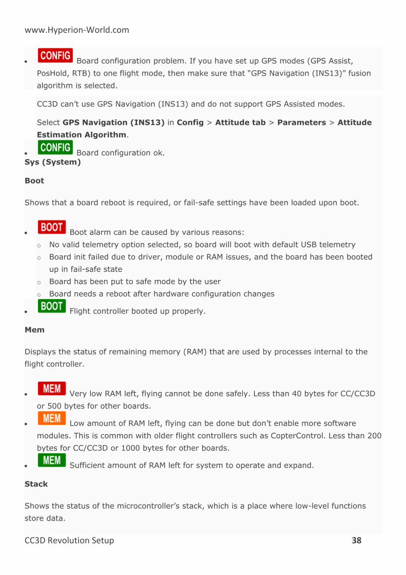
CC3D Revolution Setup 38
Board configuration problem. If you have set up GPS modes (GPS Assist,
PosHold, RTB) to one flight mode, then make sure that “GPS Navigation (INS13)” fusion
algorithm is selected.
CC3D can’t use GPS Navigation (INS13) and do not support GPS Assisted modes.
Select GPS Navigation (INS13) in Config > Attitude tab > Parameters > Attitude
Estimation Algorithm.
Board configuration ok.
Sys (System)
Boot
Shows that a board reboot is required, or fail-safe settings have been loaded upon boot.
Boot alarm can be caused by various reasons:
o No valid telemetry option selected, so board will boot with default USB telemetry
o Board init failed due to driver, module or RAM issues, and the board has been booted
up in fail-safe state
o Board has been put to safe mode by the user
o Board needs a reboot after hardware configuration changes
Flight controller booted up properly.
Mem
Displays the status of remaining memory (RAM) that are used by processes internal to the
flight controller.
Very low RAM left, flying cannot be done safely. Less than 40 bytes for CC/CC3D
or 500 bytes for other boards.
Low amount of RAM left, flying can be done but don’t enable more software
modules. This is common with older flight controllers such as CopterControl. Less than 200
bytes for CC/CC3D or 1000 bytes for other boards.
Sufficient amount of RAM left for system to operate and expand.
Stack
Shows the status of the microcontroller’s stack, which is a place where low-level functions
store data.
www.Hyperion-World.com
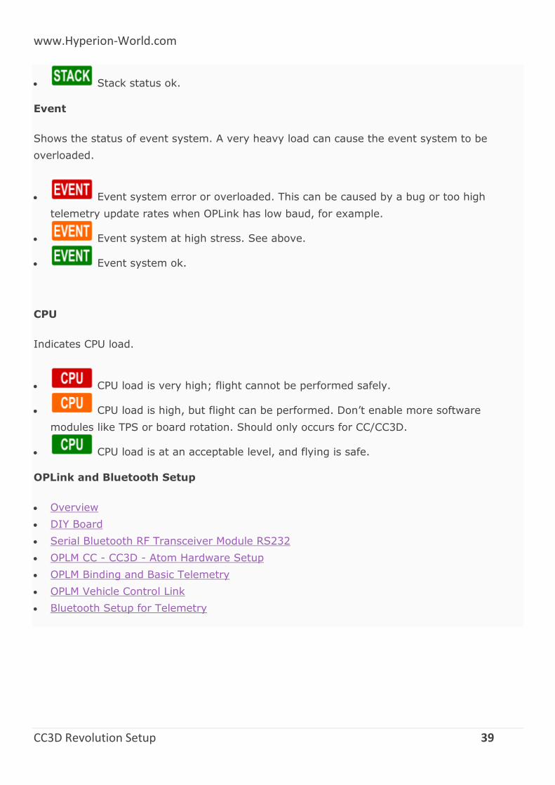
CC3D Revolution Setup 39
Stack status ok.
Event
Shows the status of event system. A very heavy load can cause the event system to be
overloaded.
Event system error or overloaded. This can be caused by a bug or too high
telemetry update rates when OPLink has low baud, for example.
Event system at high stress. See above.
Event system ok.
CPU
Indicates CPU load.
CPU load is very high; flight cannot be performed safely.
CPU load is high, but flight can be performed. Don’t enable more software
modules like TPS or board rotation. Should only occurs for CC/CC3D.
CPU load is at an acceptable level, and flying is safe.
OPLink and Bluetooth Setup
Overview
DIY Board
Serial Bluetooth RF Transceiver Module RS232
OPLM CC - CC3D - Atom Hardware Setup
OPLM Binding and Basic Telemetry
OPLM Vehicle Control Link
Bluetooth Setup for Telemetry
www.Hyperion-World.com
CC3D Revolution Setup 40
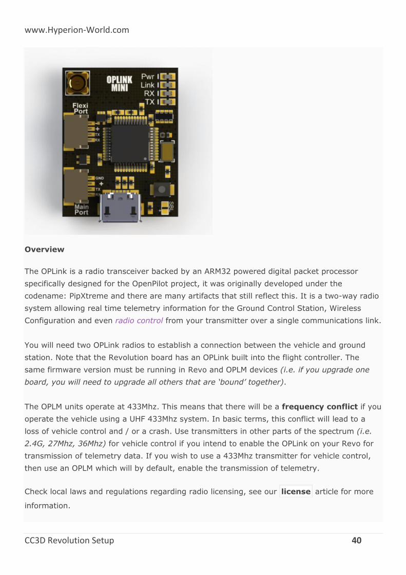
Overview
The OPLink is a radio transceiver backed by an ARM32 powered digital packet processor
specifically designed for the OpenPilot project, it was originally developed under the
codename: PipXtreme and there are many artifacts that still reflect this. It is a two-way radio
system allowing real time telemetry information for the Ground Control Station, Wireless
Configuration and even radio control from your transmitter over a single communications link.
You will need two OPLink radios to establish a connection between the vehicle and ground
station. Note that the Revolution board has an OPLink built into the flight controller. The
same firmware version must be running in Revo and OPLM devices (i.e. if you upgrade one
board, you will need to upgrade all others that are ‘bound’ together).
The OPLM units operate at 433Mhz. This means that there will be a frequency conflict if you
operate the vehicle using a UHF 433Mhz system. In basic terms, this conflict will lead to a
loss of vehicle control and / or a crash. Use transmitters in other parts of the spectrum (i.e.
2.4G, 27Mhz, 36Mhz) for vehicle control if you intend to enable the OPLink on your Revo for
transmission of telemetry data. If you wish to use a 433Mhz transmitter for vehicle control,
then use an OPLM which will by default, enable the transmission of telemetry.
Check local laws and regulations regarding radio licensing, see our license article for more
information.
www.Hyperion-World.com
CC3D Revolution Setup 41
The device that is intended to undertake the most of the transmissions should be allocated as
the Co-ordinator. If you wish to use the OPLM for vehicle control, then the Co-ordinator
should be the OPLM device in your transmitter module at the ground station. In this case, the
Revo or another OPLink will be acting as a slave receiver but will also transmit telemetry
information to your ground station which is comprised of another OPLM connected to a
computer that is running the OP GCS Flight Data page. Alternatively, if you wish to simply
receive telemetry data at the ground station, then the Revo should be configured as the Co-
ordinator. Configuration instructions are provided below and linked-to pages.
First time use with OPLM
When you first try to use your OPLM with the GCS, it will not be automatically picked up by
the GCS. You first need to go into the ‘Firmware’ tab and click ‘Upgrade & Erase’ while the
OPLink is disconnected. Then plug in OPLink when the upgrade process asks for it. Once this
has been done, your OPLM board will show up at the bottom of your GCS as a connected
device. The configuration page icon at the bottom of the page icon list may
be hidden without scrolling down, depending on the size of your computer screen.
OPLink Mini
100mW Standalone Radio Modem
3 IO Ports: Micro-B USB, Mainport & Flexiport
MMCX Antenna Connector.
Weight: 4g
Dimensions: 20mm x 29mm
Input Voltage: +5v
OPLink Revo
100mW integrated radio modem included the OpenPilot Revolution platform.
MMCX Antenna Connector.
Directly integrated, no external connections or power needed.
Dipole whip antenna
OPLM CC - CC3D - Atom Hardware Setup
OPLM Binding and Basic Telemetry
OPLM Vehicle Control Link
DIY Board
Pls download below file for Schematics, PCB Layout, Gerbers, BOM.
www.Hyperion-World.com
CC3D Revolution Setup 42
http://opwiki.readthedocs.io/en/latest/_downloads/OPLink%20Mini.zip
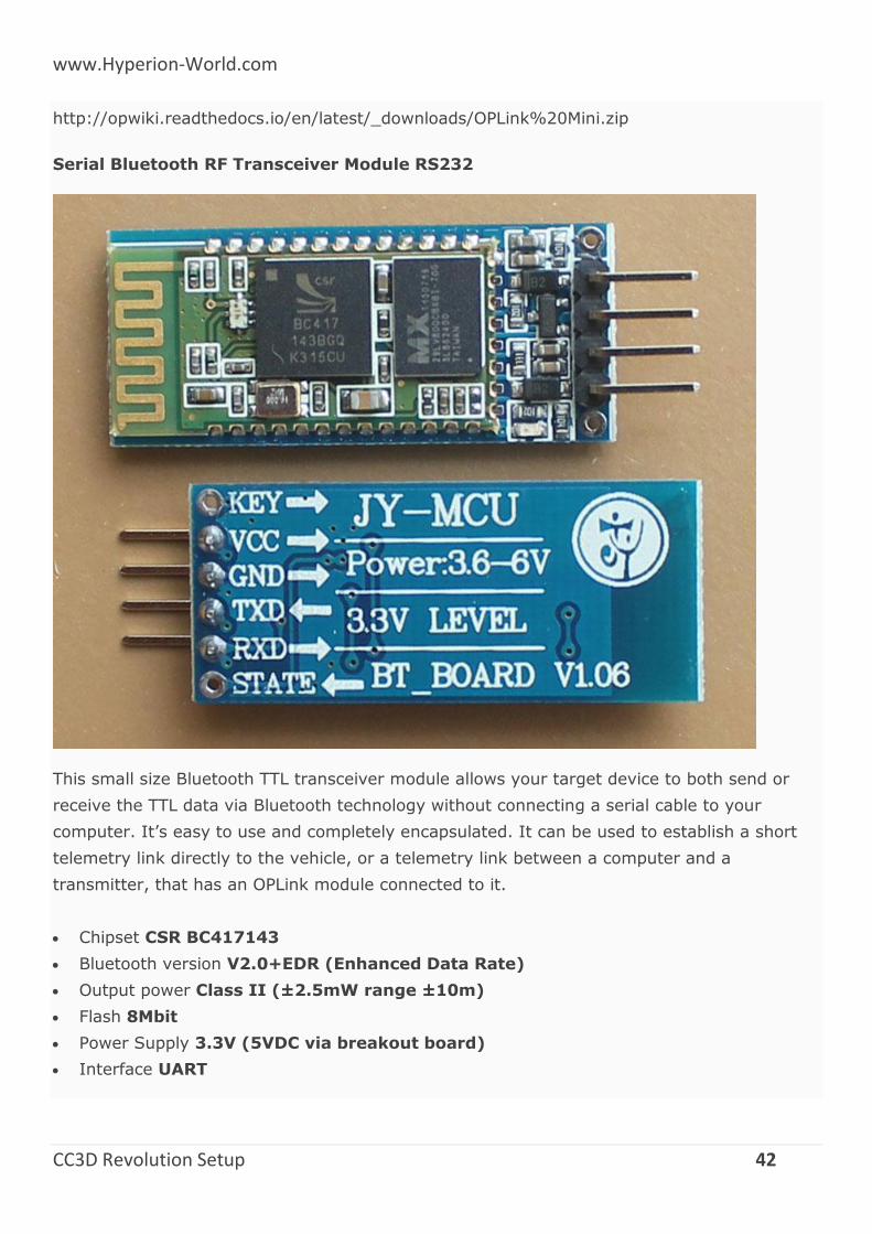
Serial Bluetooth RF Transceiver Module RS232
This small size Bluetooth TTL transceiver module allows your target device to both send or
receive the TTL data via Bluetooth technology without connecting a serial cable to your
computer. It’s easy to use and completely encapsulated. It can be used to establish a short
telemetry link directly to the vehicle, or a telemetry link between a computer and a
transmitter, that has an OPLink module connected to it.
Chipset CSR BC417143
Bluetooth version V2.0+EDR (Enhanced Data Rate)
Output power Class II (±2.5mW range ±10m)
Flash 8Mbit
Power Supply 3.3V (5VDC via breakout board)
Interface UART
www.Hyperion-World.com
CC3D Revolution Setup 43
This configuration guide covers the displayed serial Bluetooth module. It’s available in many
different internet shops (e.g. Ebay, Goodluckbuy, BlueSkyRC). The boards generally ship for
around 10$ - 20$. Although the hardware is the same, several software or firmware revisions
exist.
Different input voltage versions
Important
There are different versions available; 3VDC or 5VDC. You want the 5VDC version in order to
connect directly to CopterControl. This module has an on-board voltage regulator.
The voltage input must be clearly mentioned. Typically, these boards can handle a power
supply between 3.6VDC ~ 6.0VDC when an on-board voltage regulator is available
Check for the input & output voltage which is mostly mentioned on the module diagram.
Bluetooth Setup for Telemetry
OPLM CC - CC3D - Atom Hardware Setup
Summary
This page will walk you through how to set up the hardware connections that are required for
CopterControl, CC3D and Atom OPLink operation. All OpenPilot boards support connection
with the OPLink module. The OPLink connection can be used for telemetry and/or vehicle
control.
The OPLink module will get it’s power from the flight controller’s external power, so unlike
Revolution, the modem will not get powered on by just plugging in the USB to the flight
controller. Make sure that you have the same OpenPilot firmware versions on both the flight
controller and OPLink modem. All the examples below are shown with a CC3D flight controller
board, but they can be applied to CopterControl and Atom, also.
Hardware connections
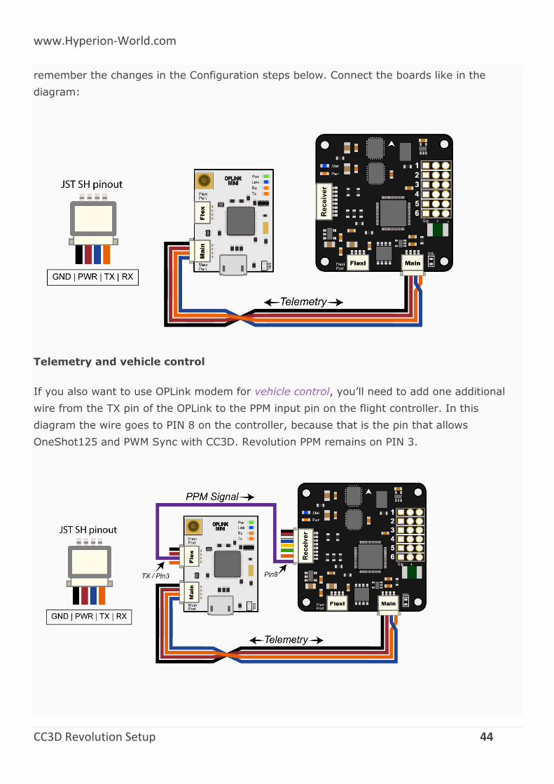
Telemetry only
The OPLink will be set up to talk bidirectional telemetry with the flight controller. You can use
a regular OpenPilot 4-pin JST SH cable to connect the two boards. It is recommended to use
Main port for both boards, but you can also use other ports to connect telemetry. Just
www.Hyperion-World.com
CC3D Revolution Setup 44
remember the changes in the Configuration steps below. Connect the boards like in the
diagram:
Telemetry and vehicle control
If you also want to use OPLink modem for vehicle control, you’ll need to add one additional
wire from the TX pin of the OPLink to the PPM input pin on the flight controller. In this
diagram the wire goes to PIN 8 on the controller, because that is the pin that allows
OneShot125 and PWM Sync with CC3D. Revolution PPM remains on PIN 3.
www.Hyperion-World.com
CC3D Revolution Setup 45
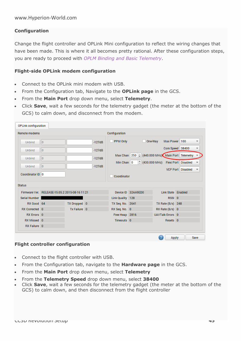
Configuration
Change the flight controller and OPLink Mini configuration to reflect the wiring changes that
have been made. This is where it all becomes pretty rational. After these configuration steps,
you are ready to proceed with OPLM Binding and Basic Telemetry.
Flight-side OPLink modem configuration
Connect to the OPLink mini modem with USB.
From the Configuration tab, Navigate to the OPLink page in the GCS.
From the Main Port drop down menu, select Telemetry.
Click Save, wait a few seconds for the telemetry gadget (the meter at the bottom of the
GCS) to calm down, and disconnect from the modem.
Flight controller configuration
Connect to the flight controller with USB.
From the Configuration tab, navigate to the Hardware page in the GCS.
From the Main Port drop down menu, select Telemetry
From the Telemetry Speed drop down menu, select 38400 Click Save, wait a few seconds for the telemetry gadget (the meter at the bottom of the
GCS) to calm down, and then disconnect from the flight controller
www.Hyperion-World.com
CC3D Revolution Setup 46
OPLM Binding and Basic Telemetry
OPLink radios can be used in several different ways: for telemetry connection only, for
telemetry + vehicle control, and for vehicle control only. The common thread for all these
uses is binding, which also leads to basic telemetry data being transmitted over the link
automatically.
This procedure will bind an OPLink mini to another OPLink, either to the integrated OPLink of
the Revolution, or to another independent OPLink module. If you are binding two stand-alone
OPLink modules together, it is recommended to first go through the OPLM CC - CC3D - Atom
Hardware Setup page in order to prepare hardware for the binding operation. For Revolution,
port setup or hardware changes are not necessary.
We will use the ground OPLink as a link coordinator, and the flight OPLink as a link slave. This
enables full telemetry capabilities and makes it possible to use the link for vehicle control. If
you are going to use OPLink for vehicle control, do this tutorial first, then proceed
to the vehicle control tutorial. If you only intend to use telemetry, you can also make the
flight OPLink the coordinator, but this does not have any additional benefits.
Antennas
Caution
From this point on, you should always have antennas connected to all OPLink modules. Neglecting this will cause permanent damage to the RF electronics.
Prerequisites
Make sure that all modules are up to date by using the GCS Firmware Update & Erase
feature, found in the Firmware tab. OPLink must be disconnected before clicking the
update button. The OPLink that is integrated into Revolution will be updated when you
update the flight controller firmware.
If you are connecting a ground OPLink to another stand-alone module, set up the
hardware first by following the OPLM CC - CC3D - Atom Hardware Setup page.
To protect your hardware from short circuits, consider mounting the OPLink module inside
a case or at least wrap it with heat shrink. DO NOT mount a bare board so that it can
touch carbon fiber frame without insulating it first (carbon fiber is conductive).
OpenPilot firmware can only support one Telemetry link at a certain time, so disable
Telemetry going to OSD or Bluetooth module etc. DO NOT disable USBTelemetry.
Check, and re-check that there is an antenna connected to both OPLink modules!
www.Hyperion-World.com
CC3D Revolution Setup 47
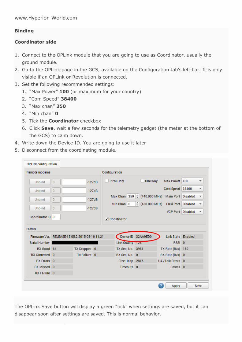
Binding
Coordinator side
1. Connect to the OPLink module that you are going to use as Coordinator, usually the
ground module.
2. Go to the OPLink page in the GCS, available on the Configuration tab’s left bar. It is only
visible if an OPLink or Revolution is connected.
3. Set the following recommended settings:
1. “Max Power” 100 (or maximum for your country)
2. “Com Speed” 38400
3. “Max chan” 250
4. “Min chan” 0
5. Tick the Coordinator checkbox
6. Click Save, wait a few seconds for the telemetry gadget (the meter at the bottom of
the GCS) to calm down.
4. Write down the Device ID. You are going to use it later
5. Disconnect from the coordinating module.
The OPLink Save button will display a green “tick” when settings are saved, but it can
disappear soon after settings are saved. This is normal behavior.
www.Hyperion-World.com
CC3D Revolution Setup 48
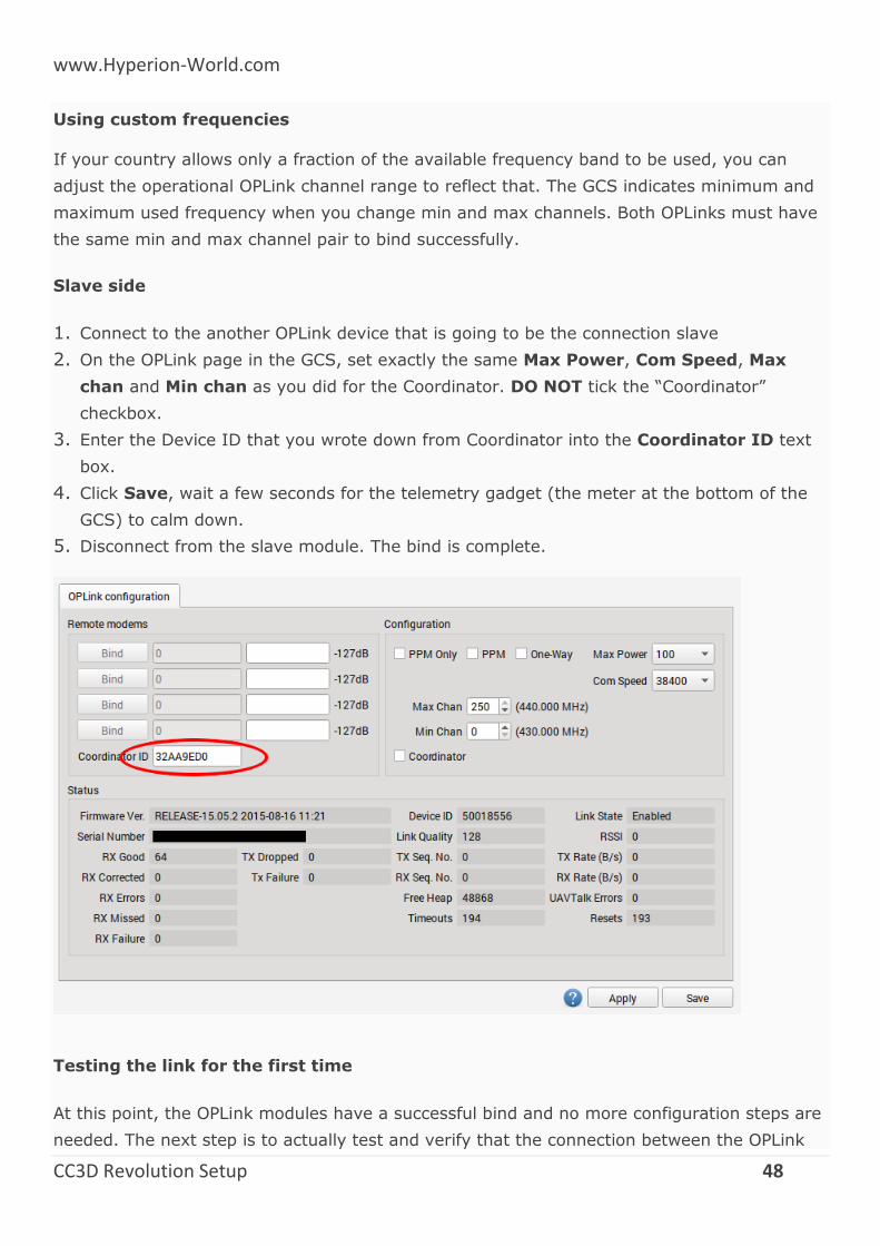
Using custom frequencies
If your country allows only a fraction of the available frequency band to be used, you can
adjust the operational OPLink channel range to reflect that. The GCS indicates minimum and
maximum used frequency when you change min and max channels. Both OPLinks must have
the same min and max channel pair to bind successfully.
Slave side
1. Connect to the another OPLink device that is going to be the connection slave
2. On the OPLink page in the GCS, set exactly the same Max Power, Com Speed, Max
chan and Min chan as you did for the Coordinator. DO NOT tick the “Coordinator”
checkbox.
3. Enter the Device ID that you wrote down from Coordinator into the Coordinator ID text
box.
4. Click Save, wait a few seconds for the telemetry gadget (the meter at the bottom of the
GCS) to calm down.
5. Disconnect from the slave module. The bind is complete.
Testing the link for the first time
At this point, the OPLink modules have a successful bind and no more configuration steps are
needed. The next step is to actually test and verify that the connection between the OPLink
www.Hyperion-World.com
CC3D Revolution Setup 49
devices works properly. All OpenPilot devices should be powered off and disconnected from
your PC before testing. This is because the modules need a proper power cycle to apply the
changes we made, and because only one telemetry connection can be supported at a time.
This means that if you have USB connected to the flight controller, only the USB connection
gets telemetry, and the OPLink does not.
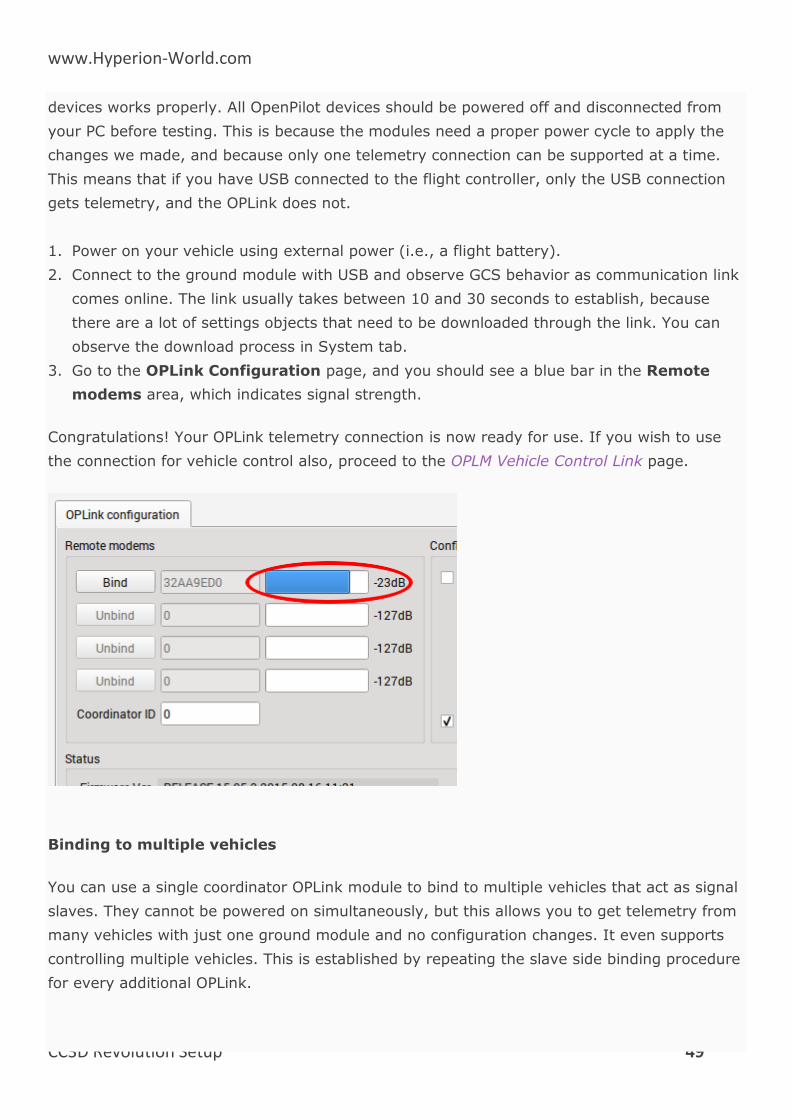
1. Power on your vehicle using external power (i.e., a flight battery).
2. Connect to the ground module with USB and observe GCS behavior as communication link
comes online. The link usually takes between 10 and 30 seconds to establish, because
there are a lot of settings objects that need to be downloaded through the link. You can
observe the download process in System tab.
3. Go to the OPLink Configuration page, and you should see a blue bar in the Remote
modems area, which indicates signal strength.
Congratulations! Your OPLink telemetry connection is now ready for use. If you wish to use
the connection for vehicle control also, proceed to the OPLM Vehicle Control Link page.
Binding to multiple vehicles
You can use a single coordinator OPLink module to bind to multiple vehicles that act as signal
slaves. They cannot be powered on simultaneously, but this allows you to get telemetry from
many vehicles with just one ground module and no configuration changes. It even supports
controlling multiple vehicles. This is established by repeating the slave side binding procedure
for every additional OPLink.
www.Hyperion-World.com
CC3D Revolution Setup 50
Multiple Slaves
Caution
Make sure that only one vehicle at a time is powered with a flight battery, or you may have a second vehicle power up unexpectedly when you arm!
Using higher COM speed
OPLink supports higher COM speeds than 38400. If necessary, you can safely bump it up to
57600. After that, the range of the link decreases significantly. This makes it possible to
transmit larger amounts of data and raise the update periods of various data objects
(manually, in data object meta data). With faster data rate, ridiculous object update speeds
can be achieved, but at the cost of range.
Using Bluetooth module with OPLink
It is possible to connect a Bluetooth module to OPLink, and establish a completely wireless
telemetry link. In this setup, telemetry data is first transmitted between OPLink modules, and
then from ground OPLink module to Bluetooth module, and finally a computer or a
smartphone with integrated Bluetooth chip. Setup instructions can be found in the Bluetooth
Setup for Telemetry page.
One way operation
If for some reason you want to only transmit with the other module, and receive with the
other one, you can tick “One way” in both OPLink module settings. It will enable a special
mode where only the coordinator module can transmit packets. The slave module receives
packets normally.
Vehicle control link only
For those extra long or safety critical flights OPLink can be brought into a special mode where
nothing but PPM vehicle control signal is transmitted from coordinator to slave. This enables a
custom communication speed and protocol in OPLink. You can enable it by ticking “PPM
Only” at both OPLink module configs. The control link has to be set up normally using OPLM
Vehicle Control Link page instructions.
OPLM Vehicle Control Link
These instructions will walk you through on how to use your existing OPLink telemetry
connection for vehicle control. The instructions consist of hardware and software side. Set up
the hardware side first and then do the necessary hardware configuration changes. If you
www.Hyperion-World.com
CC3D Revolution Setup 51
have not done binding yet for the OPLink modules, do that first using OPLM Binding and Basic
Telemetry page instructions, and return to this tutorial after that.
For Revolution, no hardware configuration is required at the flight controller side. For CC,
CC3D and Atom, a PPM wire has to be connected from the OPLink module to the flight
controller. The instructions for how to prepare those flight controllers for control link can be
found on OPLM CC - CC3D - Atom Hardware Setup page. If you do not have the PPM wire
connected, do it now, and then return to this page.
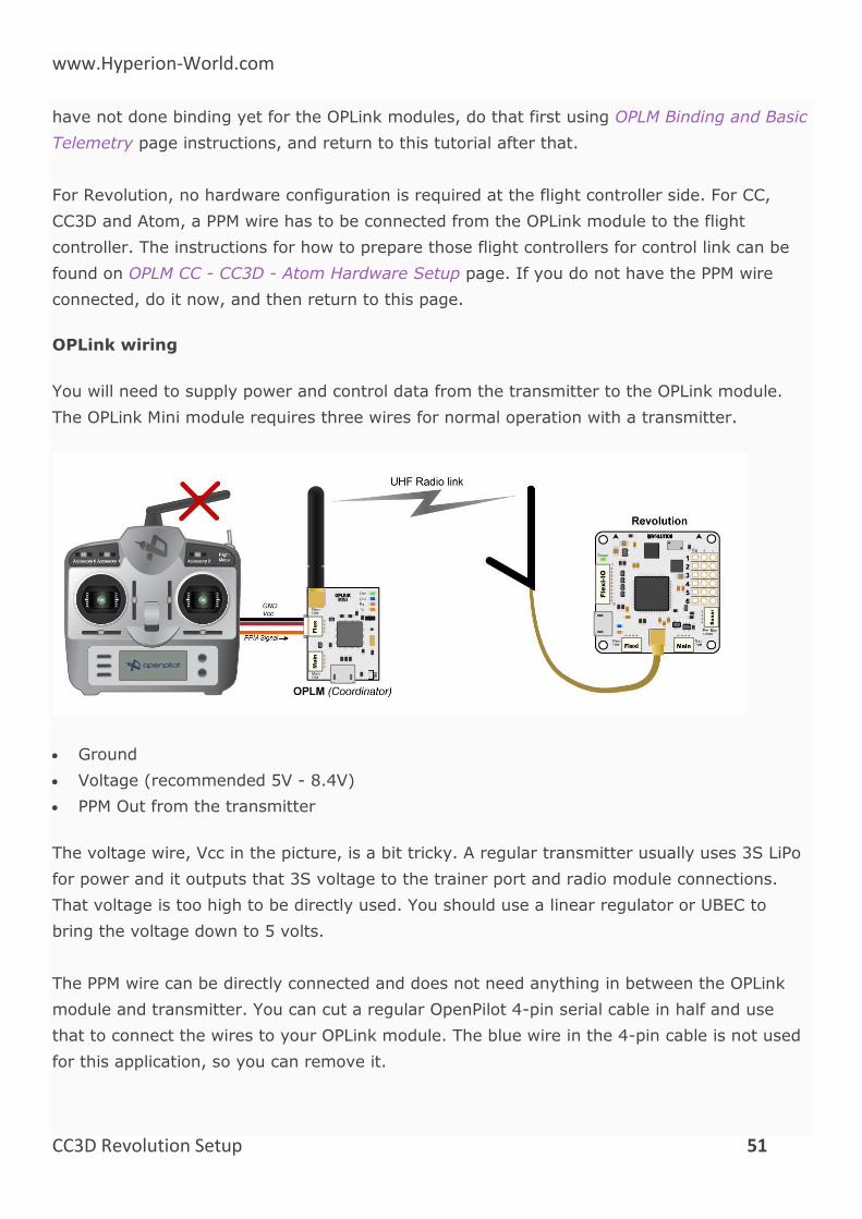
OPLink wiring
You will need to supply power and control data from the transmitter to the OPLink module.
The OPLink Mini module requires three wires for normal operation with a transmitter.
Ground
Voltage (recommended 5V - 8.4V)
PPM Out from the transmitter
The voltage wire, Vcc in the picture, is a bit tricky. A regular transmitter usually uses 3S LiPo
for power and it outputs that 3S voltage to the trainer port and radio module connections.
That voltage is too high to be directly used. You should use a linear regulator or UBEC to
bring the voltage down to 5 volts.
The PPM wire can be directly connected and does not need anything in between the OPLink
module and transmitter. You can cut a regular OpenPilot 4-pin serial cable in half and use
that to connect the wires to your OPLink module. The blue wire in the 4-pin cable is not used
for this application, so you can remove it.
www.Hyperion-World.com
CC3D Revolution Setup 52
OPLink PPM input
OPLink module is programmed to accept PPM sum between 4 and 8 channels. Recommended
PPM frame length is 22,5 milliseconds.
OPLink input voltage
Do not input higher than 8.4 volts (2S) to the OPLink module! Higher voltage will cause
permanent damage to the electronics.
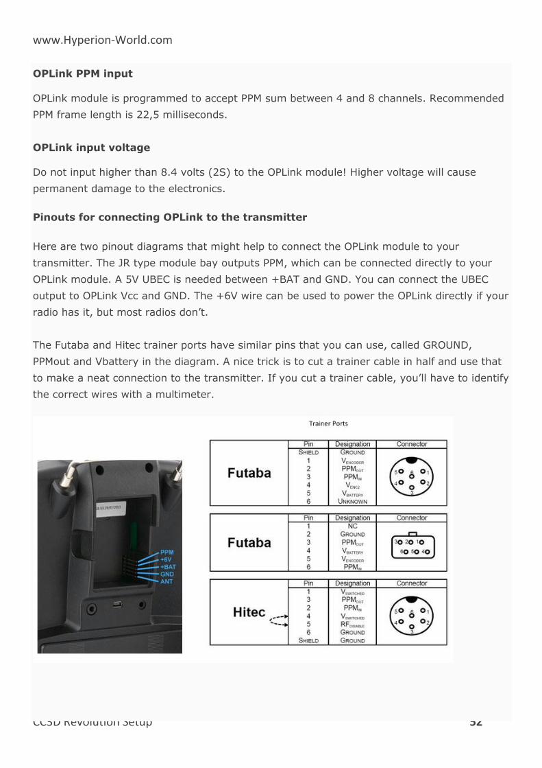
Pinouts for connecting OPLink to the transmitter
Here are two pinout diagrams that might help to connect the OPLink module to your
transmitter. The JR type module bay outputs PPM, which can be connected directly to your
OPLink module. A 5V UBEC is needed between +BAT and GND. You can connect the UBEC
output to OPLink Vcc and GND. The +6V wire can be used to power the OPLink directly if your
radio has it, but most radios don’t.
The Futaba and Hitec trainer ports have similar pins that you can use, called GROUND,
PPMout and Vbattery in the diagram. A nice trick is to cut a trainer cable in half and use that
to make a neat connection to the transmitter. If you cut a trainer cable, you’ll have to identify
the correct wires with a multimeter.
www.Hyperion-World.com
CC3D Revolution Setup 53
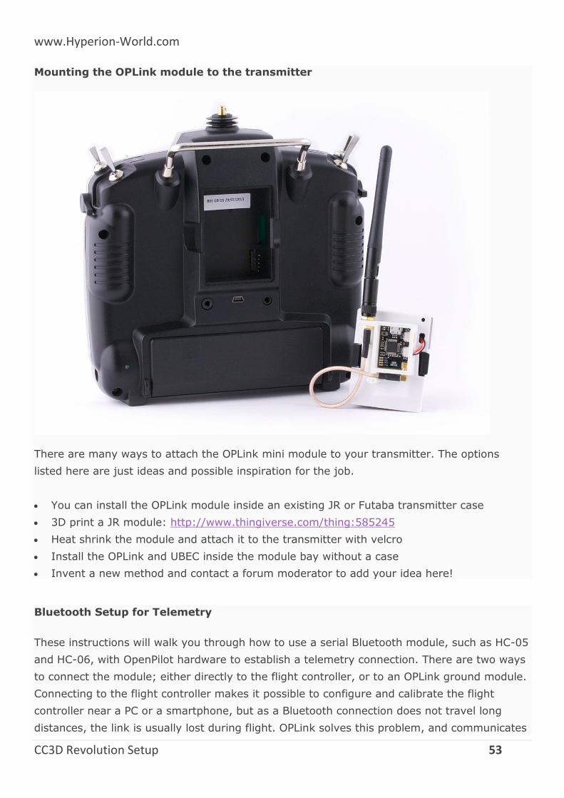
Mounting the OPLink module to the transmitter
There are many ways to attach the OPLink mini module to your transmitter. The options
listed here are just ideas and possible inspiration for the job.
You can install the OPLink module inside an existing JR or Futaba transmitter case
3D print a JR module: http://www.thingiverse.com/thing:585245
Heat shrink the module and attach it to the transmitter with velcro
Install the OPLink and UBEC inside the module bay without a case
Invent a new method and contact a forum moderator to add your idea here!
Bluetooth Setup for Telemetry
These instructions will walk you through how to use a serial Bluetooth module, such as HC-05
and HC-06, with OpenPilot hardware to establish a telemetry connection. There are two ways
to connect the module; either directly to the flight controller, or to an OPLink ground module.
Connecting to the flight controller makes it possible to configure and calibrate the flight
controller near a PC or a smartphone, but as a Bluetooth connection does not travel long
distances, the link is usually lost during flight. OPLink solves this problem, and communicates
www.Hyperion-World.com
CC3D Revolution Setup 54
telemetry data from the vehicle to ground. Then Bluetooth connection can be used to connect
a PC or a smartphone to the OPLink ground module. This is especially useful when using
OPLink for vehicle control + telemetry.
No matter which hardware configuration you choose, the Bluetooth module’s configuration
procedure is basically the same. HC-05 and HC-06 Bluetooth modules are factory configured
to 9600 baud rate, 8 data bit, 1 stop bit and no parity serial connection. The baud rate must
be increased to 38400 to match with that of the OPLink. Alternatively, 57600 baud can be
used if you are connecting the Bluetooth module directly to the flight controller, or if you use
57600 baud with OPLink.
Configuring the Bluetooth module
Hardware connections
To change the baud rate of the Bluetooth module, you must connect to the module with a
serial link. You can either use an FTDI USB to serial adapter, or your OpenPilot flight
controller to connect to the Bluetooth module. Both establish the same goal. If you have an
FTDI adapter it is recommended to use that, because it does not require any configuration
steps like the flight controller does for Virtual COM port ComBridge operation.
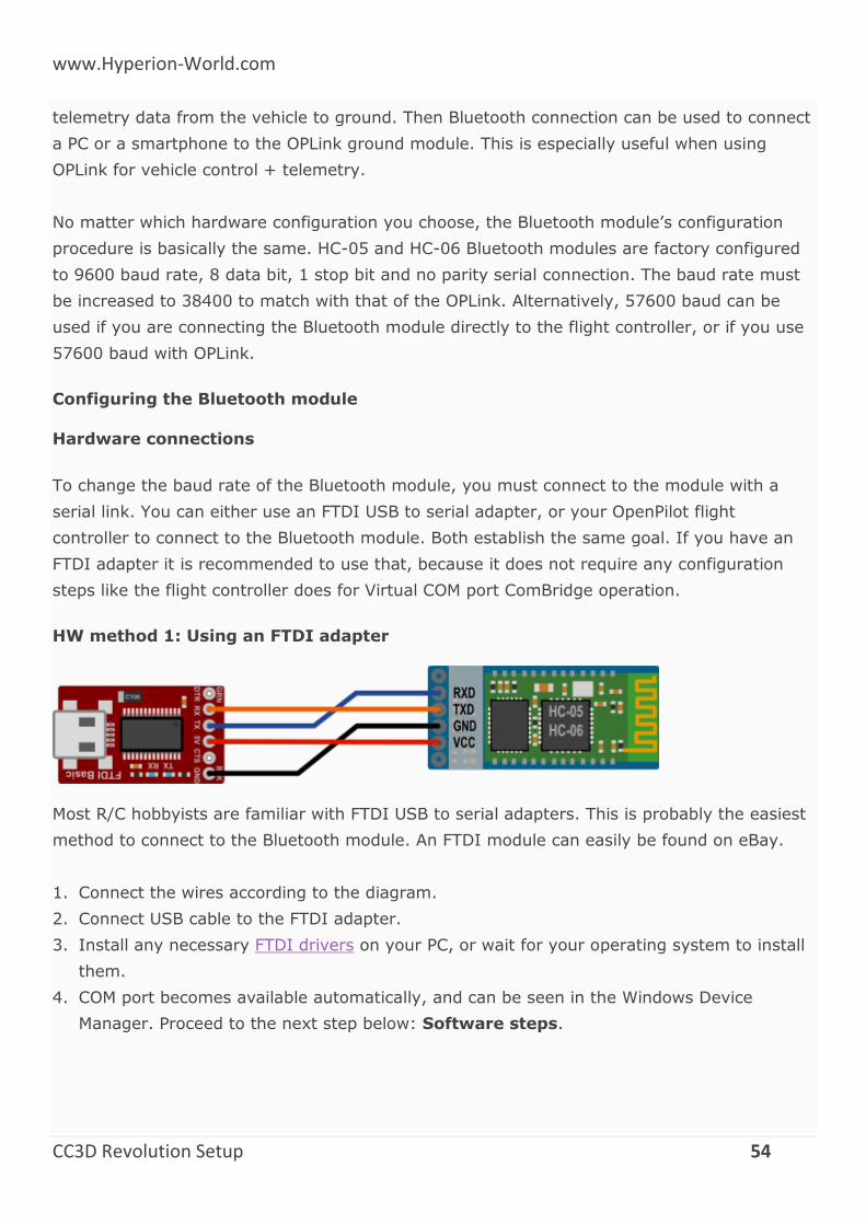
HW method 1: Using an FTDI adapter
Most R/C hobbyists are familiar with FTDI USB to serial adapters. This is probably the easiest
method to connect to the Bluetooth module. An FTDI module can easily be found on eBay.
1. Connect the wires according to the diagram.
2. Connect USB cable to the FTDI adapter.
3. Install any necessary FTDI drivers on your PC, or wait for your operating system to install
them.
4. COM port becomes available automatically, and can be seen in the Windows Device
Manager. Proceed to the next step below: Software steps.
www.Hyperion-World.com
CC3D Revolution Setup 55
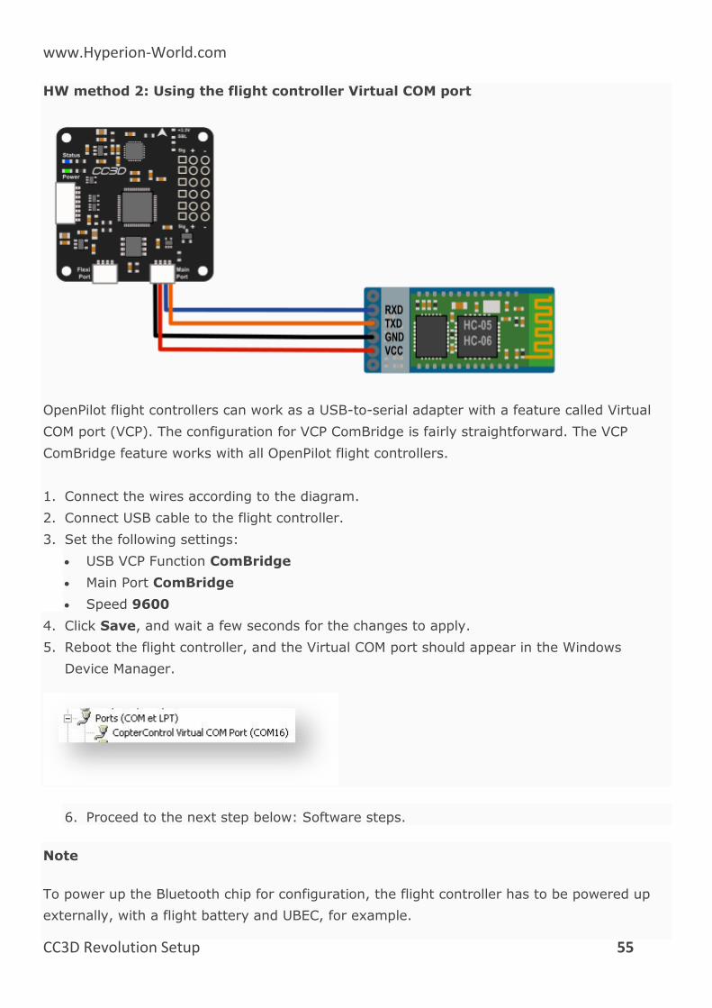
HW method 2: Using the flight controller Virtual COM port
OpenPilot flight controllers can work as a USB-to-serial adapter with a feature called Virtual
COM port (VCP). The configuration for VCP ComBridge is fairly straightforward. The VCP
ComBridge feature works with all OpenPilot flight controllers.
1. Connect the wires according to the diagram.
2. Connect USB cable to the flight controller.
3. Set the following settings:
USB VCP Function ComBridge
Main Port ComBridge
Speed 9600
4. Click Save, and wait a few seconds for the changes to apply.
5. Reboot the flight controller, and the Virtual COM port should appear in the Windows
Device Manager.
6. Proceed to the next step below: Software steps.
Note
To power up the Bluetooth chip for configuration, the flight controller has to be powered up
externally, with a flight battery and UBEC, for example.
www.Hyperion-World.com
CC3D Revolution Setup 56
Software steps
In this section, the Bluetooth module will be configured to correct the baud rate. You can also
customize the Bluetooth unit’s name. The Bluetooth module expects to be called AT
commands in the COM port, which you can either write in a command line, or automatically
send with a Windows tool that former OpenPilot developer PT_Dreamer wrote. Connect your
Bluetooth module to your PC with either the FTDI or VCP ComBridge. VCP ComBridge usage
requires external power to the flight controller.
If you have not decided on the baud rate you want to use for the Bluetooth module, now is
the time. Recommended settings are 38400 for usage with OPLink and 57600 for usage
directly with your flight controller. Remember the setting, it is a good idea to use a marker
pen and write it on the Bluetooth module.
Configuration method 1: Windows configuration software
1. Download Bluetooth configuration software from the link below.
2. Extract the files and launch the configuration program by clicking on the .exe file.
3. Select COM port and baud 9600, and click Connect.
4. Select the appropriate Speed (baud rate; i.e., 38400 or 57600), Name and Pin code.
5. Click Write values.
6. Configuration is done.
7. Undo the USB VCP Com Bridge changes if you used a flight controller for the connection.
Configuration software download from below link.
http://opwiki.readthedocs.io/en/latest/_downloads/BT_Cong_Qt4.zip
Configuration method 2: Command line
While the configuration software above is by far the easiest method on a Windows system,
Mac and Linux users will have to use command line to configure the Bluetooth module. There
are many terminal applications you can choose from. One option for Windows and Linux
is PuTTY, and for Mac CoolTerm. No matter which terminal application you use, connect to the
COM port that the FTDI or VCP Com Bridge is in with 9600 baud rate, 8 data bit, 1 stop bit &
no parity serial connection.
When serial connection is open in the terminal application, proceed with the following steps,
all CAPS:
1. Send “AT”, the module should answer OK.
www.Hyperion-World.com
CC3D Revolution Setup 57
2. Send “AT+NAMEOpenPilot”, this sets the module’s name to “OpenPilot”.
3. Send “AT+BAUD6” for 38400 baud rate OR “AT+BAUD7” for 57600 baud rate.
4. Close the terminal application.
5. Configuration is done.
6. Undo the USB VCP Com Bridge changes if you used a flight controller for the connection.
Connecting the Bluetooth module to OpenPilot devices
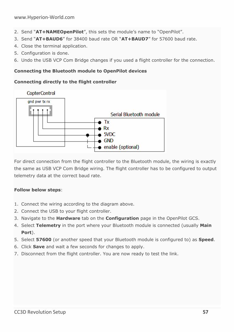
Connecting directly to the flight controller
For direct connection from the flight controller to the Bluetooth module, the wiring is exactly
the same as USB VCP Com Bridge wiring. The flight controller has to be configured to output
telemetry data at the correct baud rate.
Follow below steps:
1. Connect the wiring according to the diagram above.
2. Connect the USB to your flight controller.
3. Navigate to the Hardware tab on the Configuration page in the OpenPilot GCS.
4. Select Telemetry in the port where your Bluetooth module is connected (usually Main
Port).
5. Select 57600 (or another speed that your Bluetooth module is configured to) as Speed.
6. Click Save and wait a few seconds for changes to apply.
7. Disconnect from the flight controller. You are now ready to test the link.
www.Hyperion-World.com
CC3D Revolution Setup 58
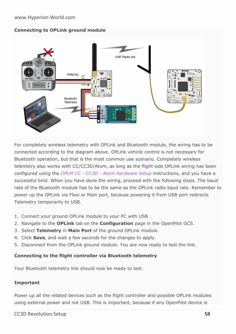
Connecting to OPLink ground module
For completely wireless telemetry with OPLink and Bluetooth module, the wiring has to be
connected according to the diagram above. OPLink vehicle control is not necessary for
Bluetooth operation, but that is the most common use scenario. Completely wireless
telemetry also works with CC/CC3D/Atom, as long as the flight side OPLink wiring has been
configured using the OPLM CC - CC3D - Atom Hardware Setup instructions, and you have a
successful bind. When you have done the wiring, proceed with the following steps. The baud
rate of the Bluetooth module has to be the same as the OPLink radio baud rate. Remember to
power up the OPLink via Flexi or Main port, because powering it from USB port redirects
Telemetry temporarily to USB.
1. Connect your ground OPLink module to your PC with USB .
2. Navigate to the OPLink tab on the Configuration page in the OpenPilot GCS.
3. Select Telemetry in Main Port of the ground OPLink module.
4. Click Save, and wait a few seconds for the changes to apply.
5. Disconnect from the OPLink ground module. You are now ready to test the link.
Connecting to the flight controller via Bluetooth telemetry
Your Bluetooth telemetry link should now be ready to test.
Important
Power up all the related devices such as the flight controller and possible OPLink modules
using external power and not USB. This is important, because if any OpenPilot device is
www.Hyperion-World.com
CC3D Revolution Setup 59
connected via USB, other Telemetry connections will be temporarily disabled until the USB is
unplugged.
1. Connect to the Bluetooth module using your computer’s Bluetooth utilities. Use a new Pin
if you changed it, or the usual default of 1234.
2. Launch the OpenPilot GCS and select a serial COM port from the connections drop-down
menu in the bottom bar. Then click Connect. You might have to try multiple ports to find
the right one. This is the COM port that your PC’s internal Bluetooth chip automatically
creates when connection to your Bluetooth module is established.
3. Success! In the example screenshot above, the GCS is talking to an OpenPilot Revolution
via OPLink <-> Bluetooth connection that is available on Serial COM13 port. The COM port
number will most likely be different for you.
Connecting
The OpenPilot GCS will not automatically connect to Bluetooth devices. The connection has to
be opened manually by selecting a COM port, and clicking Connect.
Appendix
Bootloader Update
o Introduction
o How to Check the Bootloader Version
o Downloads
o How to Upgrade the Bootloader and Erase Settings
o LED Behavior
o FAQs
JST-SH Connectors
o Description
o Uses
o Datasheets
Bootloader Update
Introduction
The bootloader is a small piece of software resident on the flight controller which is started as
soon as the board is powered. It performs hardware checks and loads and executes the
firmware. It also handles the USB port to communicate with GCS to support bootloader and
firmware updates.
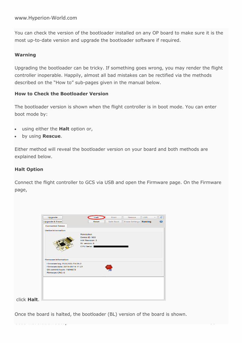
www.Hyperion-World.com
CC3D Revolution Setup 60
You can check the version of the bootloader installed on any OP board to make sure it is the
most up-to-date version and upgrade the bootloader software if required.
Warning
Upgrading the bootloader can be tricky. If something goes wrong, you may render the flight
controller inoperable. Happily, almost all bad mistakes can be rectified via the methods
described on the “How to” sub-pages given in the manual below.
How to Check the Bootloader Version
The bootloader version is shown when the flight controller is in boot mode. You can enter
boot mode by:
using either the Halt option or,
by using Rescue.
Either method will reveal the bootloader version on your board and both methods are
explained below.
Halt Option
Connect the flight controller to GCS via USB and open the Firmware page. On the Firmware
page,
click Halt.
Once the board is halted, the bootloader (BL) version of the board is shown.
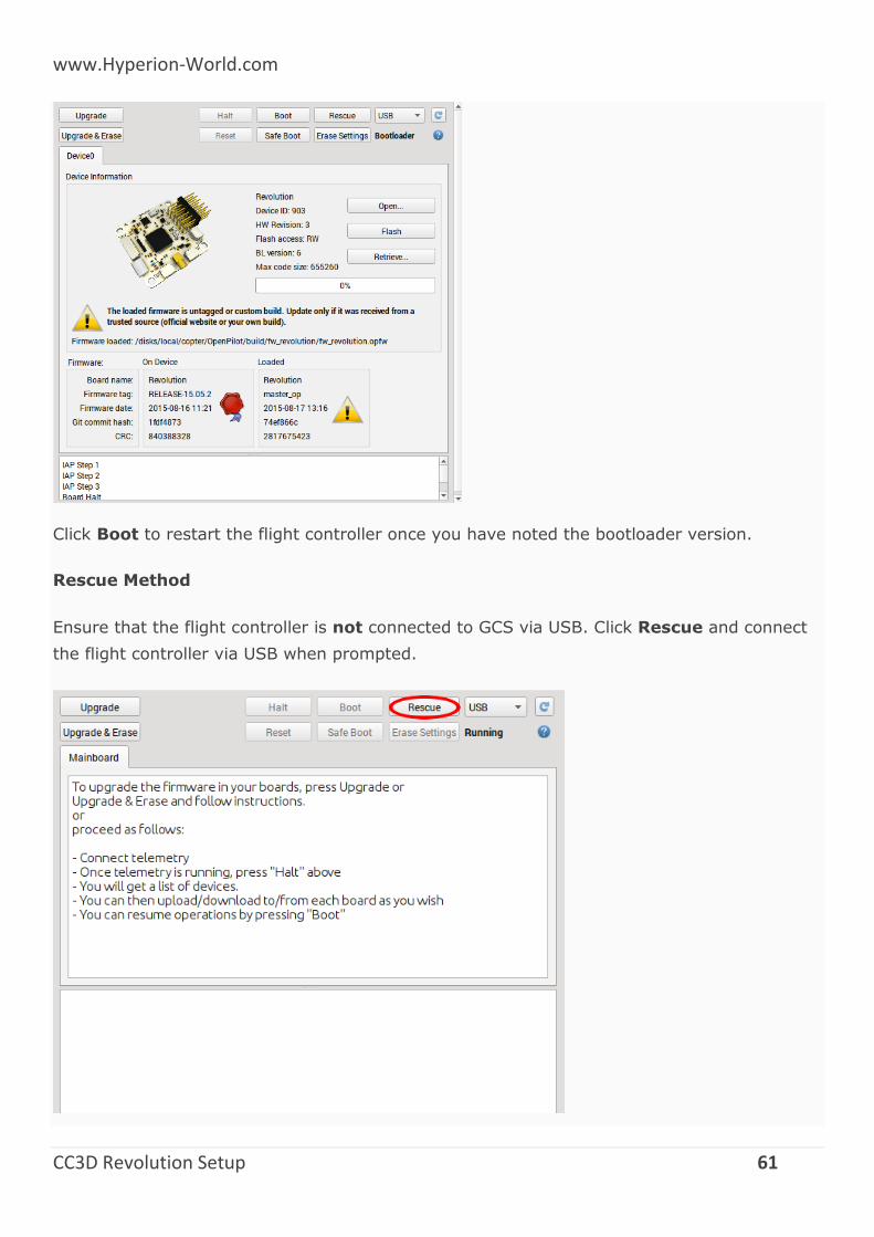
www.Hyperion-World.com
CC3D Revolution Setup 61
Click Boot to restart the flight controller once you have noted the bootloader version.
Rescue Method
Ensure that the flight controller is not connected to GCS via USB. Click Rescue and connect
the flight controller via USB when prompted.
www.Hyperion-World.com
CC3D Revolution Setup 62
When the board is connected, its bootloader (BL) version is shown. Click Boot to restart the
flight controller once you have noted the bootloader version.
Downloads
Bootloader Versions
Version 1 - First bootloader version which was loaded onto all CopterControl boards.
Version 2 - Safe boot capabilities were added to prevent the user from being locked out
of the board due to a bad hardware configuration.
Version 3 - Added different USB serial numbers for bootloader and firmware. This helps
Windows separate the two functions of the board by making it think there are two
different boards connected. Twitching servo movement during the board start has been
eliminated.
Version 4 - Added support for internal settings erasure so that no more special firmware
is required; simply enter boot mode and click Erase Settings (CC/CC3D/Atom and OPLM)
Version 5 - Added better F4 processor support (Revo and OSD)
The bootloaders for CopterControl (CC), CopterControl3D (CC3D), Atom, Revolution (Revo),
OPLink mini (OPLM) and On Screen Display (OSD) are available for download below.
Caution
All OP boards are different and require the appropriate bootloader to be installed, please
ensure you download and use the correct version listed below.
Also note that you should have the appropriate GCS installed (in most cases, the latest
version) on your PC when you flash the new bootloader so that the followup Auto Update you
perform will automatically install the correct version of firmware that is embedded in the
version of the GCS on your PC.
The PCB for CC or CC3D boards should have “CopterControl” or “CC3D” printed clearly on the
board. This indicates which bootloader needs to be flashed to the board.
Version 3 bootloaders can only be used with GCS versions 12.10.2 or older. Version 4
bootloaders can only be used with GCS versions 13.06.01 and newer.
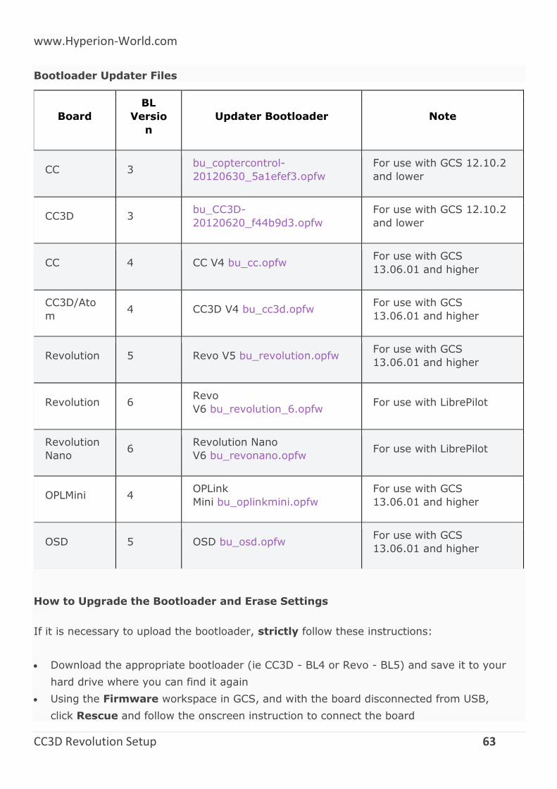
www.Hyperion-World.com
CC3D Revolution Setup 63
Bootloader Updater Files
Board
BL
Versio
n
Updater Bootloader Note
CC 3 bu_coptercontrol-
20120630_5a1efef3.opfw
For use with GCS 12.10.2
and lower
CC3D 3 bu_CC3D-
20120620_f44b9d3.opfw
For use with GCS 12.10.2
and lower
CC 4 CC V4 bu_cc.opfw For use with GCS
13.06.01 and higher
CC3D/Ato
m 4 CC3D V4 bu_cc3d.opfw
For use with GCS
13.06.01 and higher
Revolution 5 Revo V5 bu_revolution.opfw For use with GCS
13.06.01 and higher
Revolution 6 Revo
V6 bu_revolution_6.opfw For use with LibrePilot
Revolution
Nano 6
Revolution Nano
V6 bu_revonano.opfw For use with LibrePilot
OPLMini 4 OPLink
Mini bu_oplinkmini.opfw
For use with GCS
13.06.01 and higher
OSD 5 OSD bu_osd.opfw For use with GCS
13.06.01 and higher
How to Upgrade the Bootloader and Erase Settings
If it is necessary to upload the bootloader, strictly follow these instructions:
Download the appropriate bootloader (ie CC3D - BL4 or Revo - BL5) and save it to your
hard drive where you can find it again
Using the Firmware workspace in GCS, and with the board disconnected from USB,
click Rescue and follow the onscreen instruction to connect the board
www.Hyperion-World.com
CC3D Revolution Setup 64
After the board is detected, click Open and select the BootloaderUpdater (BU) file from
where you saved it on your hard drive
Click Flash to flash it to your board
After the flashing is complete, press Boot and wait until the blue LED is on, then flashes,
and finally goes off (normally ±15 seconds).
Wait 10 seconds more.
Disconnect the board from USB.
Click Rescue, connect the board, click Erase Settings and wait for the erasure to
complete.
Disconnect the board from USB.
Click Upgrade and follow the onscreen instruction to connect the board to automatically
install firmware.
LED Behavior
A slowly blinking blue LED indicates that the board is booted and running the firmware;
this is the normal operating mode.
Bootloader mode. A slow fading in and out of the blue LED with the green LED on indicates
that the board is in bootloader mode.
A rapidly blinking blue LED during a bootloader update indicates an error state. An invalid
bootloader image was likely detected and the update hasn’t been performed.
FAQs
What’s the difference between firmware, bootloader (BL) and bootloader updater
(BU)?
The firmware (FW) is the application to be loaded by the bootloader after the board has
been powered up and initialized. The firmware is regularly updated and newer firmware
typically include new features and bug fixes. The firmware and GCS version must match in
order to be able to configure the board.
The bootloader (BL) is a small piece of software which is started as soon as the board is
powered up. Every board ships with a bootloader preloaded and is not normally required to
be upgraded by the user.
The bootloader updater (BU) is a special firmware which is loaded by the current
bootloader and replaces the old bootloader with the new bootloader which it contains. This
approach is required because the bootloader can’t erase and overwrite itself.
The bootloader version isn’t updated after the update.
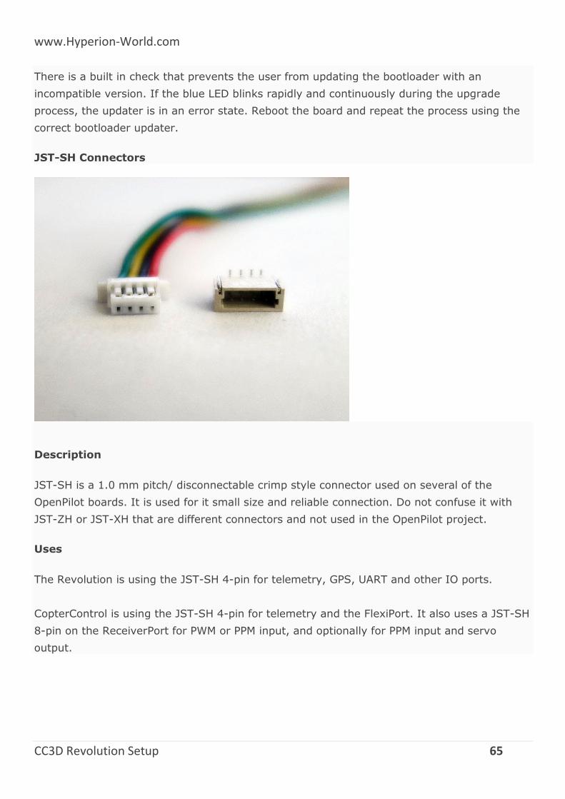
www.Hyperion-World.com
CC3D Revolution Setup 65
There is a built in check that prevents the user from updating the bootloader with an
incompatible version. If the blue LED blinks rapidly and continuously during the upgrade
process, the updater is in an error state. Reboot the board and repeat the process using the
correct bootloader updater.
JST-SH Connectors
Description
JST-SH is a 1.0 mm pitch/ disconnectable crimp style connector used on several of the
OpenPilot boards. It is used for it small size and reliable connection. Do not confuse it with
JST-ZH or JST-XH that are different connectors and not used in the OpenPilot project.
Uses
The Revolution is using the JST-SH 4-pin for telemetry, GPS, UART and other IO ports.
CopterControl is using the JST-SH 4-pin for telemetry and the FlexiPort. It also uses a JST-SH
8-pin on the ReceiverPort for PWM or PPM input, and optionally for PPM input and servo
output.