Embed Size (px)
Citation preview

CCD Color Camera
KP-FD30
Operation manual
Hitachi Kokusai Electric Inc. MGA2700
Thank you for procuring this fine Hitachi KokusaiElectric color CCD camera. Before using the camera, please read thisoperation manual carefully and keep this manualon file for ready reference in the future.


・Do not aim the camera lens at the sun. ・Do not shoot strong light or a scene including strong light.
When such a scene is shot, vertical trailings will appear. However, this is not due to failure. In case strong Tight enters the camera through the lens,
partial deterioration in picture quality will result. To obtain stable performance for long time When the camera is used continuously for long time under high ambient temperature, the inside electrical parts become deteriorated, resulting in shortening its life.
To use the camera continuously for long time, the highest temperature must be below 40℃. Cleaning ・Use a blower or a lens brush to remove dusts on the
lens or the optical filter. ・Wipe dirts on the case off with dry soft cloth. lf dirks
are hardened, wipe them off with cloth moistened with neutral detergent liquid; wipe the cover with dry cloth.
・Do not use benzine,thinner,alcohol,liquid cleaner or spray-type cleaner.
・In event dust or other debris is lodged between the CCD and optical filter, consult dealer for cleaning by an optical technician.
Power supply Be sure to use the power source specified in the Major Specifications. ・Before plugging or unplugging a connector, be sure to turn off power. To plug or unplug a connector, be sure to hold the connector section. ・Note that it will take several seconds until a picture is displayed on the monitor after power on. Handling ・Do not attempt to remove cover. ・When installing or removing a lens, be sure to use care that water or dust does not enter the inside of. the camera. Installing and storage Avoid installing or storing the camera in the following environments. ・Environments exposed to direct sunlight, rain or snow ・Environments where combustible or corrosive gas exists ・Excessively warm or cold environment (Operating ambient temperature: -10 to 50℃) ・Humid or dusty environment ・Place subjected to excessive vibration or shock ・Environment exposed to strong electric or magnetic field
Operating considerations
2) Fixed pattern noise When the camera is operated in a high temperature, fixed pattern noise may appear on the entire screen.
Following are the phenomena inherent to a CCD imaging device, and not defects1) Smear and blooming When strong light (lamp, fluorescent lamp, reflected light, etc.) is shot, pale bands are displayed vertically above and below the light. In this case, change the angle of the camera so that such strong light does not enter the camera through the lens.
3) Moire When fine patterns are shot, moire may be displayed. 4) Burning When excessively intense light comes to the CCD for a long time, the spectral filter in the CCD pixel may be deteriorated, and the colour of the corresponding portion may change.
Avoid using the camera under such condition.
Phenomena inherent to CCD imaging device

The KP-FD30 is a single CCD type RGB color camera which utilized the progressive scan CCD image sensor with square pixel for VGA format of 1 / 2-inch which adopted the RGB primary color mosaic filter.
●Analog RGB output ( 60 frame/second ) ●Small,Compact,Self-contained ●High picture quality (Digital signal processing LSI .(DSP))●CCD drive functions (Preset electronic shutter,Variable electric shutter, Auto electronic shutter,
frame / field on demand.) ●Auto level control (AVERAGE,AREA,PEAKE/AVE) ●White balance(Auto,Preset,Manual) ●Auto iris lens (galvanometer type) ●Picture adjustment
(Modes and settings can be selected and adjusted from.) ●NTSC ( VBS,Y/C,RGB ) output
It can be set as the image output of NTSC system by Switch change.
Features
General
●Camera(with C mount adaptor)
●Operation manual
Optional accessories ●DC input plug ( R03-P3F ) R03-P3F
●Lens plug ( E4-191J-100 ) E4-191J-100
●MULTI cable plug KEC-15P(Housing)
JK-SP2140(Pin cntact)
JK-C151C(Cover)
Composition
① C-mount adaptor (When using a CS-mount lens,remove the C-mount adaptor.)
② Lens mount ring
③ Lens mount screws
t up buttons [ SET/UP/DOWN ] eo output connector [ VIDEO OUT]
③
②
Section names and functions
④ Se
⑤ Vid①
⑥ DC input connector [ DC IN ] ⑦ MULTI connector [ MULTI ](Inch size screws)
⑧ Lens connector [ LENS ]
Iris control voltage input (galvanometer) type lens
⑨ Camera rear switch Set the switch according to the type of video signal.
SW-1 ON (Upper side):VGA ( progressive scan ) mode* OFF (Lower side):NTSC (2:1 interlace scan ) mode
1 2 3 4 *Factory setting is VGA(progressive) mode.
SW:ON OFF
Note: Please turn OFF SW-2 and 3 and 4. (They are not used.) ⑨
⑧
⑦ ⑥ ⑤
④

External View
Unit:mm
Connections EXP. VGA (progressive scan) mode

● Multi connector(inch size screw) ● DC input connector[DC IN]
Connectors
2
Note on lens selection 1)Observe the maximum size limit (A in the figure)
When installing the lens. Internal damage can occur If a larger lens is used.
2)Avoid using a lens that is heavier than the camera. If unavoidable, be sure to fix the lens itself on a support.
Lens flange surface
●Fixed focus lens 1) Set the lens focus ring to infinity. 2) Aim toward an object at least 20 meters distant. 3) Loosen the (2) lens mount screws and turn the lens mount ring to adjust the focus. Use care not to disturb
the lens focus ring. 4) Tighten the lens mount screws. ●Zoom lens 1) Set the lens to telephoto and
aim toward an object at least 20 meters distant.
2) Turn the lens focus ring to adjust the focus.
3) Set the lens to wide angle. Loosen the (2) lens mount
screws and turn the lens mount ring to adjust the focus. Use care not to disturb the lens focus ring.
4) Again set to telephoto but adjust the focus by turning the lend mount.
5) Repeat these steps and carefully adjust for best focus. 6) Finally, tighten the lens mount screws.
Lens DC control voltage [galvanometer] system should be used for an automatic iris lens. Although arrangement of a lens connector is based on JEITA, the length of the cable between the main part of a lens and a plug is required 150mm or more. ●Flangeback adjustment Flangeback adjustment is needed in cases where focus cannot be obtained by normal lens focus operation or focus is lost at themaximum telephoto and wide angle settings of a zoom lens. In such cases, open the lens iris and adjust as follows.
A A: Less than 4.1mm
Lens
Plug:Housing( KEC-15P ) Pin contact ( JK-SP2140 ) Cover ( JK-C151C )
Plug:R03-P3F
● Lens connector[LENS]
Plug:E4-191J-100 Note:
The length of a cable is required 150mm or more.
Pin No. Signal name 1 Damp(-)
Damp(+) 3 Drive(+) 4 Drive(-)
Pin No. Signal name A GND B +12V input C N C
Pin No. Signal name 1 R /(C)output 2 G/Y output 3 B /(VBS)output 4 WE output 5 GND (TXD/RXD) 6 VIDEO GND 7 VIDEO GND 8 VIDEO GND 9 UNREG +12V input 10 TRIG input 11 GND 12 RXD 13 HD input / HD output / SYNC output14 VD input /VD output 15 TXD

16.White balance Selectable in 3 modes ATW / AWC / MANUAL 17.Text display 24 alpha-numeric characters in one line 18.Camera setting menu Mode selection, quality-of-image adjustment 19.Remote control RS-232C level (MULTI Connector) 20. Power supply DC +12V ± 10% 21. Power
consumption Approx. 360mA (Including 60mA for auto-iris lens)
22.Lens mount C/CS mount ( Frange-back adjustment ) 23. Ambient temperature
Operating -10~+50℃/30~80%RH (*3)
Storage -20~+60℃/20~90%RH (*3) Note : If operated continuously, be sure to use at less than
+40 (104F) for long term stable performance. 24. Vibration endurance
68.65 m/s ( 10 to 200Hz, 30 minutes each on XYZ axes )
2
(*4)
(*4) Note : Do not subject to strong vibration for long periods of time. 25. Shock endurance
490.3 m/s ( vertical, horizontal, once each face )
2
26. External dimensions
58(W) x 58(H) x 48(D) mm
( not including lens and protrusions ) 27.Mass Approx. 220g ( without lens )
12. Sensitivity selection
AGC OFF/ON
Manual Gain Adjustable at AGC OFF. Limit Gain Adjustable at AGC ON (0~Approx. 18dB)
13.Electric shutter speed PRESET Select high speed shutter:OFF(1/60),1/100,
1/250, 1/500, 1/1000, 1/2000, 1/4000, 1/10000, 1/20000 1/30000, 1/50000 second (*2) low speed shutter:OFF(1/60),1/30, 1/15, 1/10, 1/7.5, 1/6, 1/5, 1/3.75 1/3, 1/2.5, 1/1.5, 1, 1.5, 2, 2.5, 3, 3.5, 4, 4.5, 5, 5.5, 6, 6.5, 7, 7.5, 8 second
(*2) An image output becomes intermittent. VARIABLE Approx. 1H steps from 1/60 second to 1/10,000
second AES 1/60 sec ~ Approx.1/50000 sec
From 1/60 second to approx. 1/50,000 second SLOW/NORMAL/FAST
EXT. TRIG ONE trigger / Fixed shutter 14.Auto level control[ALC] AVERAGE PEAK&AVERAGE AREA (Scanning area is selectable from 9 area.) 15.Auto-iris lens outputs Iris control voltage input (galvanometer) type lens
Damper 1150-ohm±10% Coupling coil impedance Drive 190-ohm±10%
6.Video signal output
RGB output RGB 0.7 Vp-p/75-ohm Positive SYNC (G on SYNC) 0.3 Vp-p Negative MULTI connector (D-sub15)
Y/C output (*1) Y 0.7 Vp-p/75-ohm Positive SYNC 0.3 Vp-p Negative C 0.3 Vp-p(Burst)/75-ohm
Subcarrier frequency 3.579545MHz MULTI connector ( D-sub15 )
VBS output (*1) Video 0.7 Vp-p/75-ohm Positive SYNC 0.3 Vp-p Negative
Burst 0.3 Vp-p 8 cycles Subcarrier frequency 3.579545MHz MULTI connector ( D-sub15 )/BNC
7.Video signal processing
Digital processing ( input 10 bits )
8.S/N ( Y signal ) More than 50dB ( AGC, enhancer and gamma off ) 9.Resolution Horizontal 440TV lines
( Y signal at center ) Vertical 480 TV lines (350 TV lines(*)) 10.Standard
sensitivity 2,000 lx (F5.6, 100IRE)
11.Minimum illumination 10 lx ( F1.4, AGC ON, 50IRE ) (*1)Only at the NTSC mode
1.Imaging device 1/2-inch progressive scan interline CCD Total number of pixels
692(H) x 504(V)
No. of effective pixels
659(H) x 494(V)
Unit cell size 9.9(H) x 9.9(V)μm ( Square pixel ) Color filter R, G, B primary color mosaic filters on chip 2.Scanning area 6.52(H) x 4.89(V)mm 3.Scanning
system Progressive scan ( VGA mode )
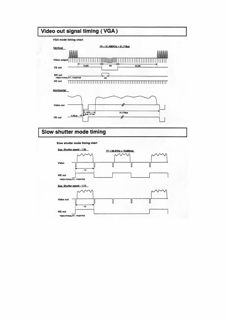
(Switch change) 2:1 interlace scan ( NTSC mode ) 4.Frequency Horizontal 31.468kHz (15.734kHz(*1) )±0.5Hz Vertical 59.94Hz 5.Sync system Internal / external ( HD/VD auto selection (*1) )
Internal sync output
HD 31.468kHz (15.734kHz (*1))±0.5Hz (Switch change) 2Vp-p/75-ohm or 5Vp-p Negative
VD 59.94Hz (Switch change) 2Vp-p/75-ohm or 5Vp-p Negative
SYNC 2Vp-p/75-ohm Negative WEN 5Vp-p Negative
External sync input
HD 31.468kHz (15.734kHz (*1) )±0.5Hz 2~5Vp-p Negative
VD 59.94Hz 2~5Vp-p Negative TRIG Low 0 Vdc High 2~5Vdc
Main specifications

5 4 3 2 1
10 9 8 7 6
15 14 13 12 11
1 2 3 4 5
6 7 8 9
TX RX
GND
Note Please perform extraction and insertion of a remote plug after turning off a camera power supply.
Remote Connection
This camera can perform remote control of various setup of A camera with a personal computer. Please perform wiring as shown in a figure to an optional remote plug, and connect with the remote connector on the back of a camera after checking wiring correctly.

When an item indicated by a mark is selected, pressing the SET button shifts to the next menu.
Main menu
Sub menu [ SUB MENU ]
WB area setting [ AREA(WB) ]
White balance setting menu [ WHITEBALANCE MENU ]
Shutter speed setting menu [ SHUTTER MENU ]
AGC setting menu [ AGC MENU ]
ALC area setting [ AREA(ALC) ]
Auto level control menu [ ALC MENU ]
Display on/off positioning setting [ POSITION ]
Camera title setting menu [ CAMERA TITLE MENU ]
Main setting menu[ MAIN MENU ]
The camera setting and adjustments can be changed to conform to conditions of use. Use the setting menu indicated on themonitor screen to check and change the settings and adjustments. The setting menu is comprised as follows.
Setting menu description
Note: lf no button is pressed, the menu display extinguishes automatically after about 5 minutes.
Menu Operation 1)Main menu[MAIN MENU] Press the SET button for at least 2 seconds to display the main menu on the monitor screen. Check the present settings at the main menu.
2)Camera title menu[CAMERA TITLE MENU] One line of up to 24 alphanumeric characters can be displayed on the screen. Camera title and a display position are set up.
Main menu
Camera title setting menu Auto Level control menu AGC setting menu Shutter speed setting menu White balance menu Sub menu End (Return to the normal screen)
●●● MAIN MENU ●●●
CAMERA TITLE :OFF
ALC :AVE
AGC :OFF
SHUTTER :OFF
WHITE BALANCE:MANUAL
SUB MENU
END
Three rear panel setup buttons are used to shift the cursor and
select items from the menus. ①Up button[UP]
Shift the cursor in the upward direction or increase an adjustment value.
②Down button[DOWN] Shift the cursor in the downward direction or decrease
an adjustment value.
③Set button[SET] Press to display the main menu or to change
a setting.
③
② ①

Note: If the ratio of (PEAK) is enlarged, a picture level may flicker. In this case (PEAK) should reduce a ratio.
MODE: PEAK/AVE
Select ALC mode [AVE, AREA, PEAK/AVE] Peak level / Average level
[0/100, 15/85, 30/70, 50/50, 75/25, 100/0] Video level adjustment (*)[-128~000~+127]
Return(Return to the main menu) End(Return to the normal screen)
(*)Press the Set button; the numerals flash. Press the Up and Down buttons to change the video level.
●● ALC MENU ●●
MODE :PEAK/AVE
PK/AV : 0/100
LEVEL : 000
RET
END
9 8 7
3 1 2
4 5 6
Detect area positions
Detect area indication
AREA(ALC)
NO.1
┏━━━━━━┓
┃ ┃
┃ ┃
┗━━━━━━┛
● Detection area setting Shift the cursor to Area Select and press the Set button todisplay the detection area select menu. There are 9 lightdetect areas selected by the Up and Down buttons. Select the areas from nos. 1 to 9 that include the subjectof main interest. After deciding the detection areas, pressthe Set button to return to the ALC menu.
MODE: AREA
Select ALC mode [AVE, AREA, PEAK/AVE] Go to the area select menu Video level(light volume)adjust (*)[-128~000~+127]
Return(Return to the main menu) End(Return to the normal screen) (*)Press the Set button;
the numerals flash. Press the Upand Down buttons to change thevideo level.
●● ALC MENU ●●
MODE :AREA
AREA SELECT:NO.1
LEVEL : 000
RET
END
ALC MODE: AVE
Select ALC mode [AVE, AREA, PEAK/AVE] Video level(light volume)adjust
(*)[-128~000~+127]
Return(Return to the main menu) End(Return to the normal screen) (*)Press the Set button;
the numerals flash. Press the Upand Down buttons to change thevideo level.
●● ALC MENU ●●
MODE :AVE
LEVEL : 000
RET
END
(3)Auto level control[ALC MENU] Automatic light control mode is set up. This control is reflectedduring automatic level control operation of an automatic iris diaphragm lens, AGC, AES, etc. There are the following three modes in automatic exposure control.
①[AVE] Responds to the average lighting over a broad area.
②[AREA] Exposure is controlled only by the luminosity level of specific area. (Scanning area is selectable from 9 area.)
③[PEAK/AVE] The peak level and the average level are used together
and exposure is controlled. (The ratio of a peak value and average value is changeable.)
Camera title position setting
CAMERA NO.1
●Title positioning setting [ POSITION ] Press the Up and Down buttons to shift the characters horizontally. Afterwards, press Set to confirm the display position and return to the main menu.
MODE: TOP/( or BOTTOM)
●● CAMERA TITLE MENU ●●
MODE :TOP
0123456789
ABCDEFGHIJKLM
NOPQRSTUVWXYZ
!?#&( ), .:;~*%
+-×/=” ’
SPACE ← → RESET
POSITION RET END
□□□□□□□□□□□□□□□□□□□□□□□
Display on/off and position [OFF, TOP, BOTTOM] Input character select table
Blank,cursorshift(left,right),character delete
Display position (left,right), Return, end Input charactet display (24 alphanumeric characters)
MODE: OFF
Display on/off and position [OFF, TOP, BOTTOM]
Return (Return to the main menu) End (Return to the normal screen)
●● CAMERA TITLE MENU ●●
MODE :OFF
RET
END

MODE: EXT TRIG
Select electric shutter speed mode
[OFF / PREST / VARIABLE / AES
/ EXT. TRIG] Select External trigger [ ONE TRIG / FIXED SHT ]
Shutter speed setting(Only FIXED SHT) [ NORMAL→1/250→1/500→
1/1000→1/2000→1/4000→
1/10000→1/50000 ] Select External trigger pulse input
polarity[ POSITIVE / NEGATIVE ] Select WEN pulse output polarity [ POSITIVE / NEGATIVE ]
●● SHUTTER MENU ●●
MODE :EXT TRIG
TRIGGER MODE :FIXED SHT
SHUTTER SPEED:NORMAL
TRIG POLARITY:POSITIVE
WEN POLARITY :POSITIVE
RET
END
MODE: AES
Select electric shutter speed mode
[OFF / PREST / VARIABLE / AES
/ EXT. TRIG] Select AES response speed
[SLOW / NORMAL / FAST]
Return (Return to the main menu) End (Return to the normal screen)
●● SHUTTER MENU ●●
MODE :AES
RESPONCE :NORMAL
RET
END
MODE: VARIABLE
●Electric shutter speed PRESET (Slow:26 steps) An image output becomes intermittent.
8.0→7.5→7.0→6.5→6.0→5.5→5.0→4.5→4.0→3.5→3.0 →2.5→2.0→1.5→1.0→1/1.50→1/2.0→1/2.50→1/3.00 →1/3.75→1/5.0→1/6.0→1/7.5→1/10→1/15→1/30→
(Fast:11 steps) 1/60→1/100→1/250→1/500→1/1000→1/2000→ 1/4000→1/10000→1/20000→1/30000→1/50000
Select electric shutter speed mode[OFF / PREST / VARIABLE / AES
/ EXT. TRIG] Variable electric shutter speed
[1/60.0 ~ Approx.1/10000] (1H Step) (*) (*)Press the Set button; the numerals
flash. Press the Up and Down buttons to change the Shutter speed.Return (Return to the main menu) End (Return to the normal screen)
●● SHUTTER MENU ●●
MODE :VARIABLE
SHUTTER SPEED:1/60.0
RET
END
The cautions at the time of slow shutter use: ●Sensitivity goes up. However, the image is output is intermittent. ●White flaws may become apparent at high Sensitivity;
these are not due to malfunction.
MODE:PRESET
Select electric shutter speed mode
[OFF / PREST / VARIABLE / AES
/ EXT. TRIG] Select preset shutter speed(*)
(*)Press the Set button; the numerals flash. Press the Up and Down buttons to change the Shutter speed. Return (Return to the main menu) End (Return to the normal screen)
●● SHUTTER MENU ●●
MODE :PRESET
SHUTTER SPEED:1/60
RET
END
MODE:OFF(1/60)
AGC:ON
5)Shutter speed setting[SHUTTER MENU] Electronic shutter mode is set up. Please set up according to the operating environment of the camera.
Select electric shutter speed mode [OFF / PREST / VARIABLE / AES
/ EXT. TRIG]
Return (Return to the main menu) End (Return to the normal screen)
●● SHUTTER MENU ●●
MODE :OFF
RET
END
4)AGC setting[AGC MENU] AGC (automatic gain control) mode is set up. Please set up according to the operating environment of the camera.
Select AGC mode[OFF / ON]
AGC maximum gain adjustment (*)[+00.0dB ~ +17.9dB]
(*)Press the Set button; the numeralsflash. Press the Up and Down buttons to change the AGC Gain.
Return (Return to the main menu) End (Return to the normal screen)
●● AGC MENU ●●
MODE :ON
AGC LIMIT :+17.9dB
RET
END
AGC:OFF
Select AGC mode[OFF / ON]
AGC fixed gain adjustment (*)[+00.0dB ~ +17.9dB]
(*)Press the Set button; the numerals flash. Press the Up and Down buttons to change the AGC Gain.
Return (Return to the main menu) End (Return to the normal screen)
●● AGC MENU ●●
MODE :OFF
FIX GAIN :+00.0dB
RET
END

6)White balance setting menu[WHITE BALANCE MENU]White balance mode is set up.Please set up according to theoperating environment of the camera.
press the Set button to return to the White balance menu.
●White balance detection area setting Shift the cursor to Area Select and press the Set button to display the White balance detection area select menu. There are 9 White balance detect areas selected by the Up and Down buttons. After deciding the detection areas,
B Gain offset fine adjustment (*)[-128~000~+127]
(*)Press the Set button; the numerals flash. Press the Up and Down buttons to change the R/B Gain offset.
Select White balance mode
[MANUAL / ATW / AWC] AWC preset start(A push on a set switch restarts AWC.) R Gain offset fine adjustment
(*)[-128~000~+127]
RET
END
●● WHITE BALANCE MENU ●●
MODE :MANUAL
R-GAIN : 000
B-GAIN : 000
Return (Return to the main menu) End (Return to the normal screen) (*)Press the Set button;
the numerals flash. Press the Upand Down buttons to change the R/B Gain.
Select White balance mode
[MANUAL / ATW / AWC]
R Gain adjustment (*)[-128~000~+127]
B Gain adjustment (*)[-128~000~+127]
MODE: MANUAL
MODE :ATW
WB AREA :ON(NO.1)
AREA SELECT
RET
END
●● WHITE BALANCE MENU ●●
Select White balance mode
[MANUAL / ATW / AWC]
White balance detection area select mode[OFF / ON] Go to the white balance detection area select
Return (Return to the main menu) End (Return to the normal screen)
MODE: ATW
┃ ┃
┗━━━━━━┛
AREA(WB)
NO.1
┏━━━━━━┓
┃ ┃
White balance detection area
Detect area positions
6 5 4
2 1 3
7 8 9
B-GAIN OFFSET: 000
RET
END
●● WHITE BALANCE MENU ●●
MODE :AWC
PRESET START :PUSH SET
R-GAIN OFFSET: 000
MODE:AWC
●● SUB MENU ●●
ITEM :PRESET
SYNC MODE : HD/VD
H PHASE : 000
Camera initialize(Press the Up and Down buttons simultaneously for 2 seconds to return the initial setting.)
(*)Press the Set button; the numerals flash. Press the Up and Down buttons to change the H phase.
OUTPUT :R,G,B
SYNC/HD OUT :SYNC
SYNC ON G :OFF
LENS TYPE :MANUAL
CAMERA RESET:PUSH SET
Adjustment item selection
[PICTURE / PRESET] Synchronized mode[INT. / HD/VD] H Phase adjustment (*)[-128~000~+127]
Video output setup [R,G,B / Y/C,VBS] Synchronized signal output setup[SYNC / HD]
Sync on Green [OFF / ON] Lens type [MANUAL / AUTO]
ITEM: PRESET
END
RET
7)Sub menu[SUB MENU] Changing the picture quality (video response) of the cameraoutput image. Please set up according to the operating environment of the camera.
Press the Set button simultaneously for 2 seconds to return the initial setting. An underline portion is the setup at the time of factory shipments.
●Camera reset:
●● SUB MENU ●●
ITEM :PICTURE
CHROMA GAIN : 000
SHARPNESS : 000
PEDESTAL : 000
GAMMA :ON
POLARITY :POSITIVE
RET
END
the numerals flash. Press the Up and Down buttons to change the Color / Detail / Pedestal level.
ITEM: PICTURE
[PICTURE / PRESET] Color level setting(*)[-128~ ~+127] 000Detail level setting(*)[-128~000~+127]Pedestal level setting(*)[-128~000~+127]Gamma on/off
[ON (γ=0.45)/ OFF(γ=1.0)] Negative/positive[POSITIVE / NEGATIVE] Return (Return to the main menu) End (Return to the normal screen)
(*)Press the Set button;
Adjustment item selection

Internal switch setting
HD/VD External Timing chart
To access the internal switches, remove the four screws on the back panel of the camera. Carefully remove the pack panel. There are two internal switches that may need to be changed depending on the use and connection of the camera. (1)SW6001 HD/SYNC, VD input-and-output change. Upper side: output* *Factory setting is Lower side: input HD/SYNC, VD outpout. (2)SW6002 75-ohm termination change. Upper side: 75 ohm termination* *Factory setting is Lower side: No termination 75ohm termination.
2)NTSC mode
External HD
External VD
Sync output
External HD
External VD
Sync output
Even field Odd field
Even fieldOdd field
Screws
Cautions: Before removal of the back panel, make sure that power is shut off to the camera. Please remove the back panel carefully; there is a FPC cable that is connected between the back panel and the internal boards. If the back panel is forcefully removed, there is a possibility of damaging the cable and connector.
Screws
SW6001
HD/VD inputs 1)VGA mode
External HD
External VD
Sync output
SW6002


(Important) About an external trigger signal prohibition period When falling (rising) of a trigger pulse enters during the prohibition of the following figure, color reappearance may not
be carried out correctly. Please input the trigger pulse of the following specification not to input a trigger pulse during the prohibition.
VSYN
VD out
Trigger
6.5
2nV
6.5
SYNC
The period to falling (rising) of the following trigger should not be set to 2nV-2nV+2H from falling(rising) of a front trigger pulse. ( V: vertical synchronous period, n: integer)
External trigger signal prohibition period.
VSYN
External trigger signal prohibition period.


![B-K LIGHTING1].pdf · Lens Type 9 - Clear (Standard) 10 - Spread Lens* 12 - Soft Focus Lens* 13 - Rectilinear Lens* Shielding 11 - Honeycomb Baffle* *Accommodates up to 2 Lens/Shielding](https://img.pdfslide.net/doc/110x75/5ca1866288c993eb5d8c7029/b-k-1pdf-lens-type-9-clear-standard-10-spread-lens-12-soft-focus.jpg)