Embed Size (px)
Citation preview
Question:
This task requires you to use the CLI of Sw-AC3 to answer five multiple-choice questions. This does not require any configuration.To answer the multiple-choice questions, click on the numbered boxes in the right panel.There are five multiple-choice questions with this task. Be sure to answer all five questions before leaving this item.
Notice: All the images in this VTP LAB are used for demonstration only, you will see slightly different images in the real CCNA exam
Question 1:
What interface did Sw-AC3 associate with source MAC address 0010.5a0c.ffba ?
a) Fa0/1b) Fa0/3c) Fa0/6d) Fa0/8e) Fa0/9 f) Fa0/12
Answer: Fa 0/8
Explanation: to find out which interface associated with a given MAC address, use the show mac-address-table command. It shows the learned MAC addresses and their associated interfaces. After entering this command, you will see a MAC address table like this:
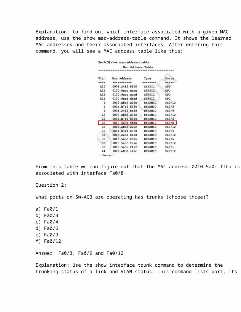
From this table we can figure out that the MAC address 0010.5a0c.ffba is associated with interface Fa0/8
Question 2:
What ports on Sw-AC3 are operating has trunks (choose three)?
a) Fa0/1b) Fa0/3c) Fa0/4d) Fa0/6e) Fa0/9 f) Fa0/12
Answer: Fa0/3, Fa0/9 and Fa0/12
Explanation: Use the show interface trunk command to determine the trunking status of a link and VLAN status. This command lists port, its mode, encapsulation and whether it is trunking. The image below shows how it works:
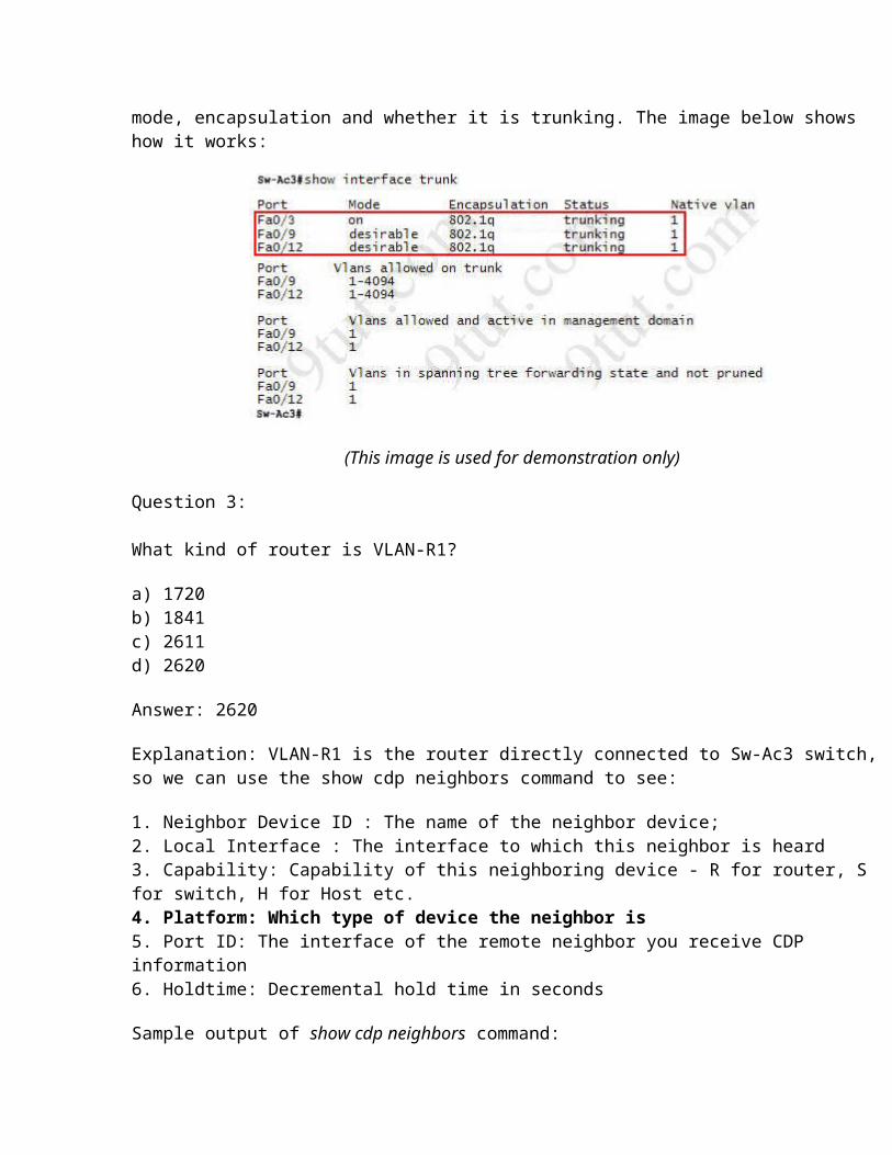
(This image is used for demonstration only)
Question 3:
What kind of router is VLAN-R1?
a) 1720b) 1841c) 2611d) 2620
Answer: 2620
Explanation: VLAN-R1 is the router directly connected to Sw-Ac3 switch, so we can use the show cdp neighbors command to see:
1. Neighbor Device ID : The name of the neighbor device;2. Local Interface : The interface to which this neighbor is heard3. Capability: Capability of this neighboring device - R for router, S for switch, H for Host etc.4. Platform: Which type of device the neighbor is5. Port ID: The interface of the remote neighbor you receive CDP information6. Holdtime: Decremental hold time in seconds
Sample output of show cdp neighbors command:
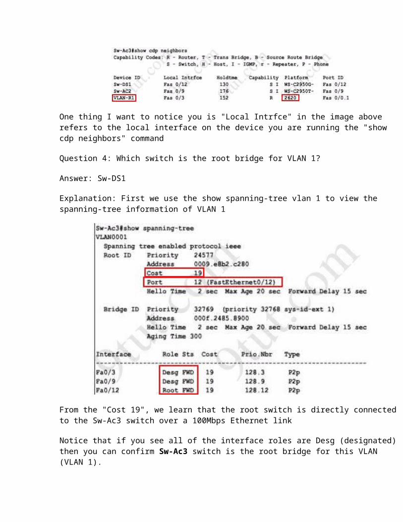
One thing I want to notice you is "Local Intrfce" in the image above refers to the local interface on the device you are running the "show cdp neighbors" command
Question 4: Which switch is the root bridge for VLAN 1?
Answer: Sw-DS1
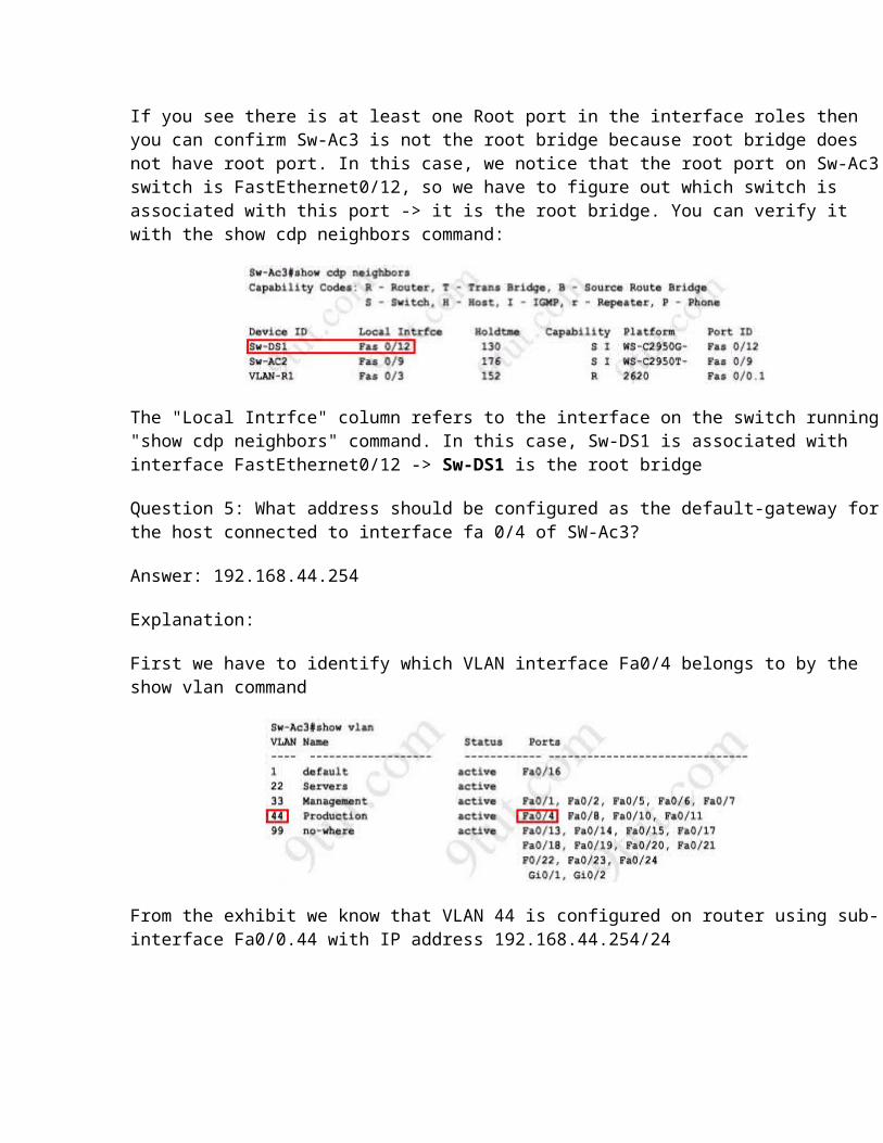
Explanation: First we use the show spanning-tree vlan 1 to view the spanning-tree information of VLAN 1
From the "Cost 19", we learn that the root switch is directly connected to the Sw-Ac3 switch over a 100Mbps Ethernet link
Notice that if you see all of the interface roles are Desg (designated) then you can confirm Sw-Ac3 switch is the root bridge for this VLAN (VLAN 1).
If you see there is at least one Root port in the interface roles then you can confirm Sw-Ac3 is not the root bridge because root bridge does not have root port. In this case, we notice that the root port on Sw-Ac3 switch is FastEthernet0/12, so we have to figure out which switch is associated with this port -> it is the root bridge. You can verify it with the show cdp neighbors command:
The "Local Intrfce" column refers to the interface on the switch running "show cdp neighbors" command. In this case, Sw-DS1 is associated with interface FastEthernet0/12 -> Sw-DS1 is the root bridge
Question 5: What address should be configured as the default-gateway for the host connected to interface fa 0/4 of SW-Ac3?
Answer: 192.168.44.254
Explanation:
First we have to identify which VLAN interface Fa0/4 belongs to by the show vlan command
From the exhibit we know that VLAN 44 is configured on router using sub-interface Fa0/0.44 with IP address 192.168.44.254/24
Therefore the default gateway of the host should be 192.168.44.254
Question 6: From which switch did Sw-Ac3 receive VLAN information ?
Answer: Sw-AC2
Explanation: to view the VTP configuration information, use the show vtp status command
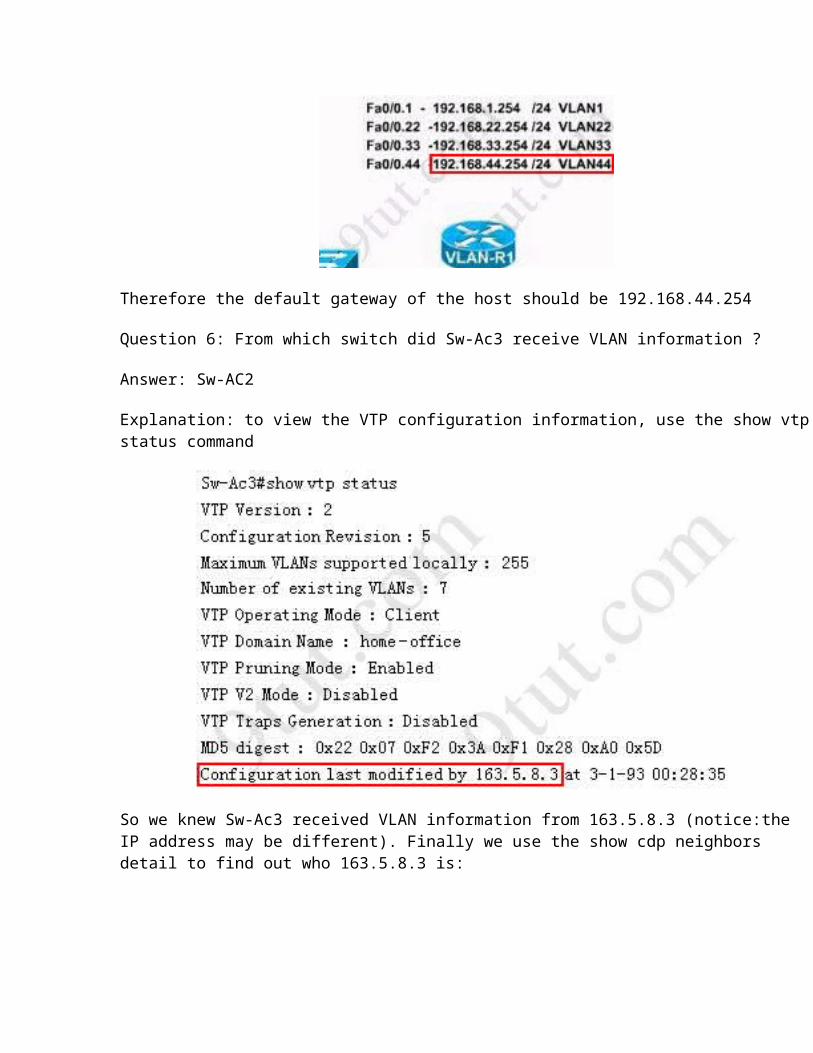
So we knew Sw-Ac3 received VLAN information from 163.5.8.3 (notice:the IP address may be different). Finally we use the show cdp neighbors detail to find out who 163.5.8.3 is:
Question 7: Refer to the exibit, SwX was taken out of the production network for maintenance. It will be reconnected to the Fa 0/16 port of Sw-Ac3. What happens to the network when it is reconnected and a trunk exists between the two switches?
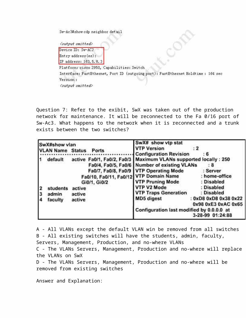
A - All VLANs except the default VLAN win be removed from all switchesB - All existing switches will have the students, admin, faculty, Servers, Management, Production, and no-where VLANsC - The VLANs Servers, Management, Production and no-where will replace the VLANs on SwXD - The VLANs Servers, Management, Production and no-where will be removed from existing switches
Answer and Explanation:
First we should view the VTP configuration of switch Sw-Ac3 by using the show vtp status command on Sw-Ac3
Notice that its configuration revision number is 5 and VTP Domain Name is home-office
Next, from the exhibit we know that SwX has a revision number of 6, which is greater than that of Sw-Ac3 switch, and both of them have same VTP Domain Name called "home-office".
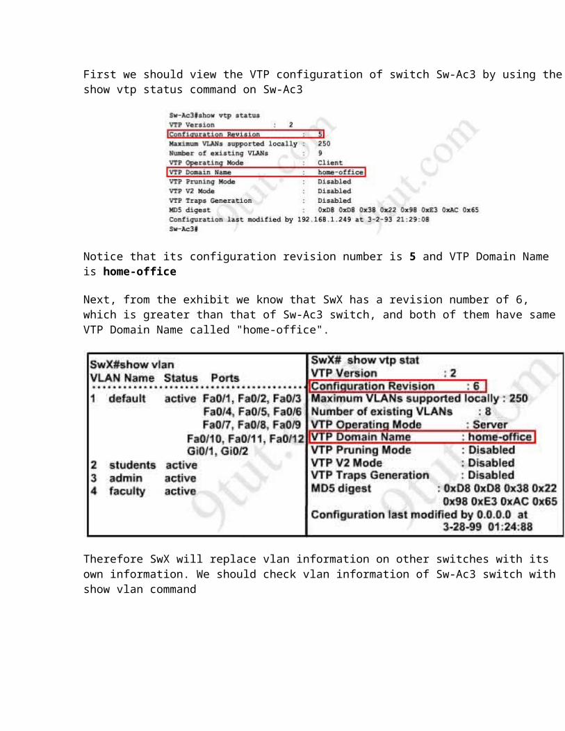
Therefore SwX will replace vlan information on other switches with its own information. We should check vlan information of Sw-Ac3 switch with show vlan command
So the correct answer is D - The VLANs Servers, Management, Production and no-where will be removed from existing switches
Please notice that in the real CCNA exam you may see a different configuration revision of Sw-Ac3 or of SwX. In general, which switch has a higher revision number it will become the updater and other switches will overwrite their current databases with the new information received from the updater (provided that they are on the same domain and that switch is not in transparent mode).In particular, if the revision number of SwX is lower than that of Sw-Ac3, the answer should be "C - The VLANs Servers, Management, Production and no-where will replace the VLANs on SwX".
Also, some recent comments have said that the new switch's VTP Operating Mode is Server but the answer is still the same.
Question 8:

Out of which ports will a frame be forwarded that has source mac-address 0010.5a0c.fd86 and destination mac-address 000a.8a47.e612? (Choose three)
A - Fa0/8B - Fa0/3C - Fa0/1D - Fa0/12
Answer: B C D
Explanation:
First we check to see which ports the source mac-address and the destination mac-address belong to by using show mac-address-table command
We notice that the source mac-address 0010.5a0c.fd86 is listed in the table and it belongs to Vlan 33 but we can't find the destination mac-address 000a.8a47.e612 in this table. In this case, the switch will flood to all ports of Vlan 33 and flood to all the trunk links, except the port it received this frame (port Fa0/6). Therefore from the output above, we can figure out it will flood this frame to Fa0/1, Fa0/3 and Fa0/12.
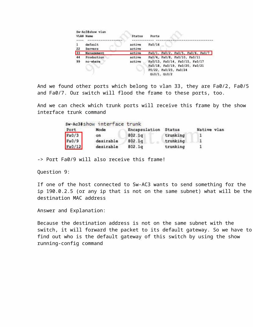
Please notice that the "show mac-address-table" command just lists information that was learned by the switch, it means that there can be other ports besides Fa0/1, Fa0/3 and Fa0/12 belong to Vlan 33. You can use the show vlan command to see which ports belong to vlan 33

And we found other ports which belong to vlan 33, they are Fa0/2, Fa0/5 and Fa0/7. Our switch will flood the frame to these ports, too.
And we can check which trunk ports will receive this frame by the show interface trunk command
-> Port Fa0/9 will also receive this frame!
Question 9:
If one of the host connected to Sw-AC3 wants to send something for the ip 190.0.2.5 (or any ip that is not on the same subnet) what will be the destination MAC address
Answer and Explanation:
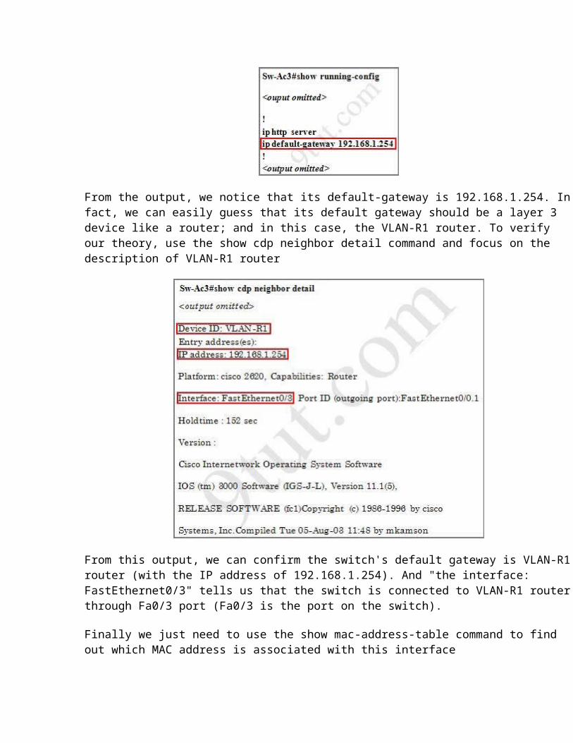
Because the destination address is not on the same subnet with the switch, it will forward the packet to its default gateway. So we have to find out who is the default gateway of this switch by using the show running-config command
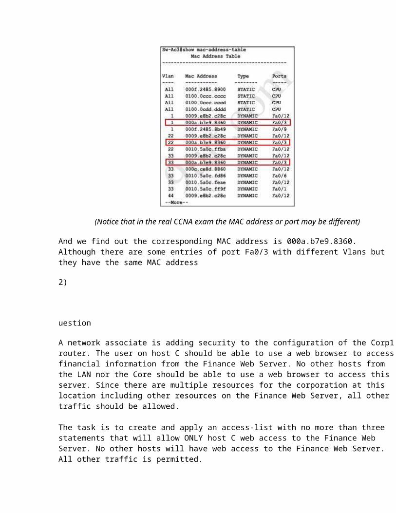
From the output, we notice that its default-gateway is 192.168.1.254. In fact, we can easily guess that its default gateway should be a layer 3 device like a router; and in this case, the VLAN-R1 router. To verify our theory, use the show cdp neighbor detail command and focus on the description of VLAN-R1 router
From this output, we can confirm the switch's default gateway is VLAN-R1 router (with the IP address of 192.168.1.254). And "the interface: FastEthernet0/3" tells us that the switch is connected to VLAN-R1 router through Fa0/3 port (Fa0/3 is the port on the switch).
Finally we just need to use the show mac-address-table command to find out which MAC address is associated with this interface
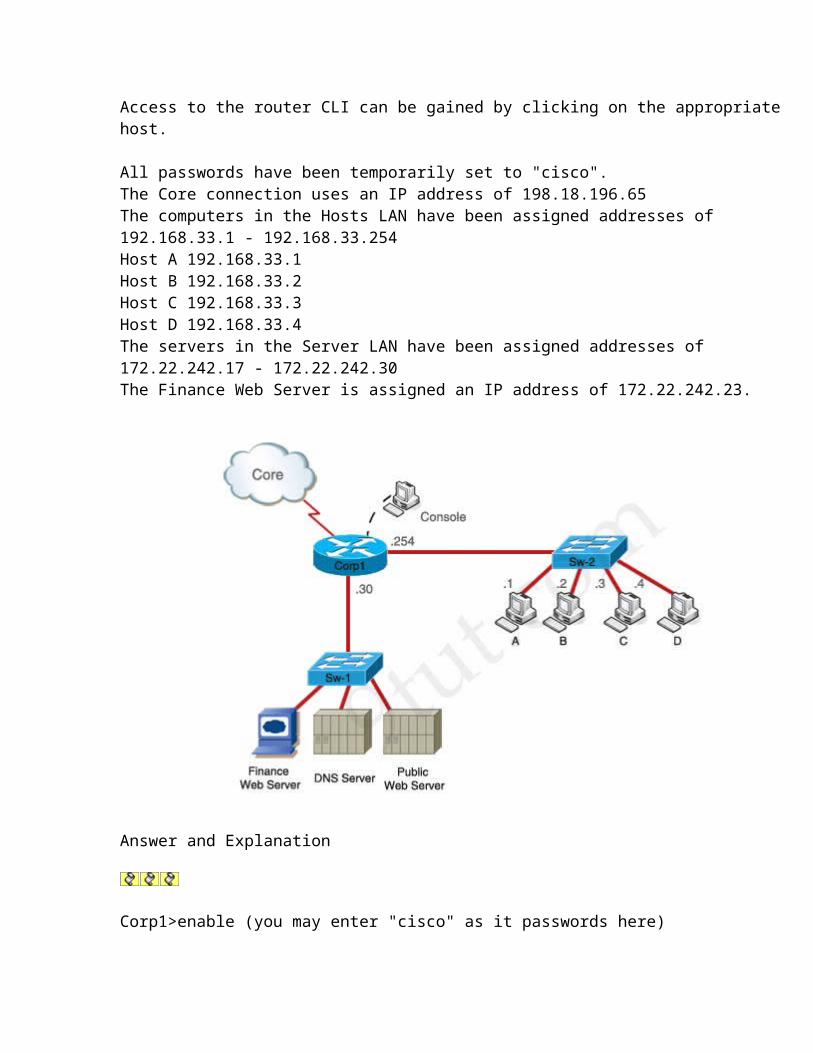
(Notice that in the real CCNA exam the MAC address or port may be different)
And we find out the corresponding MAC address is 000a.b7e9.8360. Although there are some entries of port Fa0/3 with different Vlans but they have the same MAC address
2)
uestion
A network associate is adding security to the configuration of the Corp1 router. The user on host C should be able to use a web browser to access financial information from the Finance Web Server. No other hosts from the LAN nor the Core should be able to use a web browser to access this server. Since there are multiple resources for the corporation at this location including other resources on the Finance Web Server, all other traffic should be allowed.
The task is to create and apply an access-list with no more than three statements that will allow ONLY host C web access to the Finance Web Server. No other hosts will have web access to the Finance Web Server. All other traffic is permitted.Access to the router CLI can be gained by clicking on the appropriate host.
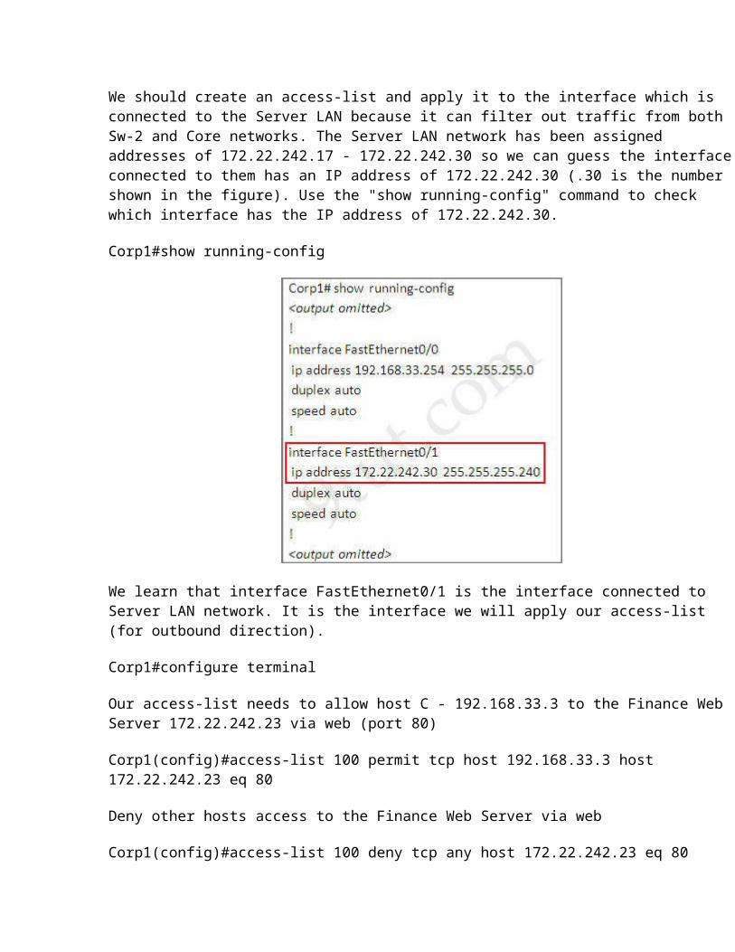
All passwords have been temporarily set to "cisco".The Core connection uses an IP address of 198.18.196.65The computers in the Hosts LAN have been assigned addresses of 192.168.33.1 - 192.168.33.254Host A 192.168.33.1Host B 192.168.33.2Host C 192.168.33.3Host D 192.168.33.4The servers in the Server LAN have been assigned addresses of 172.22.242.17 - 172.22.242.30The Finance Web Server is assigned an IP address of 172.22.242.23.
Answer and Explanation
Corp1>enable (you may enter "cisco" as it passwords here)
We should create an access-list and apply it to the interface which is connected to the Server LAN because it can filter out traffic from both Sw-2 and Core networks. The Server LAN network has been assigned addresses of 172.22.242.17 - 172.22.242.30 so we can guess the interface connected to them has an IP address of 172.22.242.30 (.30 is the number shown in the figure). Use the "show running-config" command to check which interface has the IP address of 172.22.242.30.
Corp1#show running-config
We learn that interface FastEthernet0/1 is the interface connected to Server LAN network. It is the interface we will apply our access-list (for outbound direction).
Corp1#configure terminal
Our access-list needs to allow host C - 192.168.33.3 to the Finance Web Server 172.22.242.23 via web (port 80)
Corp1(config)#access-list 100 permit tcp host 192.168.33.3 host 172.22.242.23 eq 80
Deny other hosts access to the Finance Web Server via web
Corp1(config)#access-list 100 deny tcp any host 172.22.242.23 eq 80
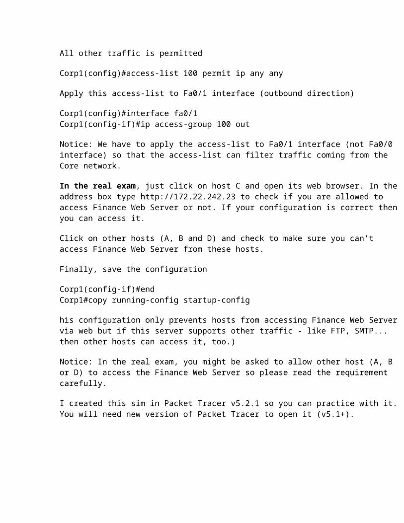
All other traffic is permitted
Corp1(config)#access-list 100 permit ip any any
Apply this access-list to Fa0/1 interface (outbound direction)
Corp1(config)#interface fa0/1Corp1(config-if)#ip access-group 100 out
Notice: We have to apply the access-list to Fa0/1 interface (not Fa0/0 interface) so that the access-list can filter traffic coming from the Core network.
In the real exam, just click on host C and open its web browser. In the address box type http://172.22.242.23 to check if you are allowed to access Finance Web Server or not. If your configuration is correct then you can access it.
Click on other hosts (A, B and D) and check to make sure you can't access Finance Web Server from these hosts.
Finally, save the configuration
Corp1(config-if)#endCorp1#copy running-config startup-config
his configuration only prevents hosts from accessing Finance Web Server via web but if this server supports other traffic - like FTP, SMTP... then other hosts can access it, too.)
Notice: In the real exam, you might be asked to allow other host (A, B or D) to access the Finance Web Server so please read the requirement carefully.
I created this sim in Packet Tracer v5.2.1 so you can practice with it. You will need new version of Packet Tracer to open it (v5.1+).
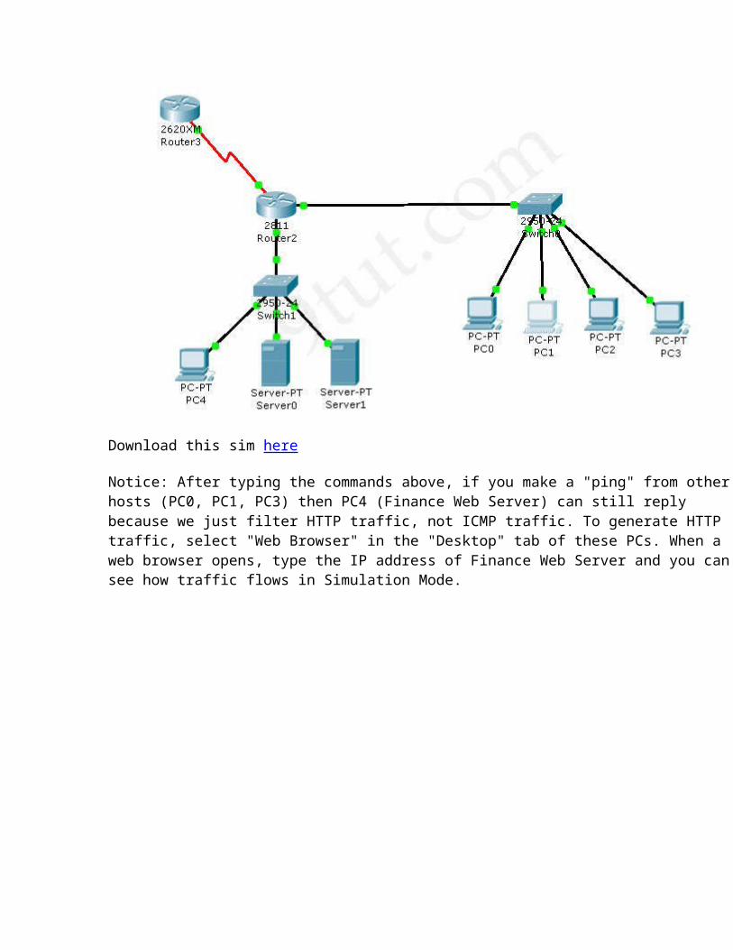
Download this sim here
Notice: After typing the commands above, if you make a "ping" from other hosts (PC0, PC1, PC3) then PC4 (Finance Web Server) can still reply because we just filter HTTP traffic, not ICMP traffic. To generate
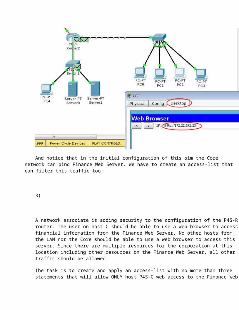
HTTP traffic, select "Web Browser" in the "Desktop" tab of these PCs. When a web browser opens, type the IP address of Finance Web Server and you can see how traffic flows in Simulation Mode.
And notice that in the initial configuration of this sim the Core network can ping Finance Web Server. We have to create an access-list that can filter this traffic too.
3)
A network associate is adding security to the configuration of the P4S-R router. The user on host C should be able to use a web browser to access financial information from the Finance Web Server. No other hosts from the LAN nor the Core should be able to use a web browser to access this server. Since there are multiple resources for the corporation at this location including other resources on the Finance Web Server, all other traffic should be allowed.
The task is to create and apply an access-list with no more than three statements that will allow ONLY host P4S-C web access to the Finance Web Server. No other hosts will have web access to the Finance Web Server. All other traffic is permitted. Access to the router CLI can be gained by clicking on the appropriate host.
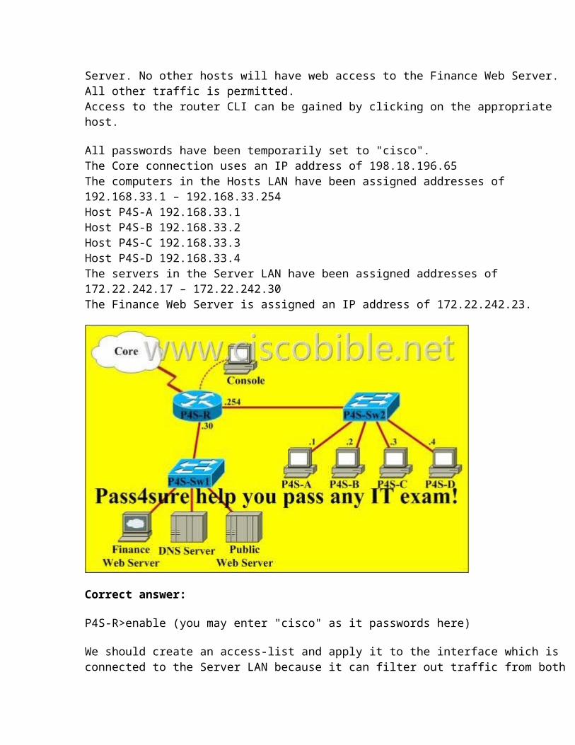
All passwords have been temporarily set to "cisco". The Core connection uses an IP address of 198.18.196.65 The computers in the Hosts LAN have been assigned addresses of 192.168.33.1 – 192.168.33.254 Host P4S-A 192.168.33.1 Host P4S-B 192.168.33.2 Host P4S-C 192.168.33.3 Host P4S-D 192.168.33.4 The servers in the Server LAN have been assigned addresses of 172.22.242.17 – 172.22.242.30 The Finance Web Server is assigned an IP address of 172.22.242.23.
Correct answer:
P4S-R>enable (you may enter "cisco" as it passwords here)
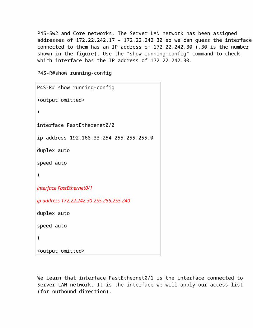
We should create an access-list and apply it to the interface which is connected to the Server LAN because it can filter out traffic from both P4S-Sw2 and Core networks. The Server LAN network has been assigned addresses of 172.22.242.17 – 172.22.242.30 so we can guess the interface connected to them has an IP address of 172.22.242.30 (.30 is the number shown in the figure). Use the "show running-config" command to check which interface has the IP address of 172.22.242.30.
P4S-R#show running-config
P4S-R# show running-config
<output omitted>
!
interface FastEtherenet0/0
ip address 192.168.33.254 255.255.255.0
duplex auto
speed auto
!
interface FastEthernet0/1
ip address 172.22.242.30 255.255.255.240
duplex auto
speed auto
!
<output omitted>
We learn that interface FastEthernet0/1 is the interface connected to Server LAN network. It is the interface we will apply our access-list (for outbound direction).
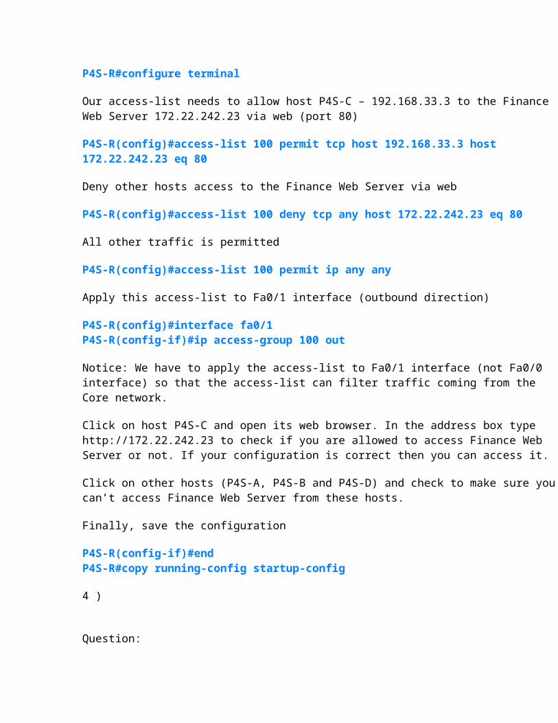
P4S-R#configure terminal
Our access-list needs to allow host P4S-C – 192.168.33.3 to the Finance Web Server 172.22.242.23 via web (port 80)
P4S-R(config)#access-list 100 permit tcp host 192.168.33.3 host 172.22.242.23 eq 80
Deny other hosts access to the Finance Web Server via web
P4S-R(config)#access-list 100 deny tcp any host 172.22.242.23 eq 80
All other traffic is permitted
P4S-R(config)#access-list 100 permit ip any any
Apply this access-list to Fa0/1 interface (outbound direction)
P4S-R(config)#interface fa0/1 P4S-R(config-if)#ip access-group 100 out
Notice: We have to apply the access-list to Fa0/1 interface (not Fa0/0 interface) so that the access-list can filter traffic coming from the Core network.
Click on host P4S-C and open its web browser. In the address box type http://172.22.242.23 to check if you are allowed to access Finance Web Server or not. If your configuration is correct then you can access it.
Click on other hosts (P4S-A, P4S-B and P4S-D) and check to make sure you can’t access Finance Web Server from these hosts.
Finally, save the configuration
P4S-R(config-if)#end P4S-R#copy running-config startup-config
4 )
Question:
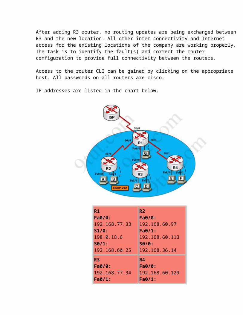
After adding R3 router, no routing updates are being exchanged between R3 and the new location. All other inter connectivity and Internet access for the existing locations of the company are working properly.The task is to identify the fault(s) and correct the router configuration to provide full connectivity between the routers.
Access to the router CLI can be gained by clicking on the appropriate host. All passwords on all routers are cisco.
IP addresses are listed in the chart below.
R1 Fa0/0: 192.168.77.33 S1/0: 198.0.18.6S0/1: 192.168.60.25
R2Fa0/0: 192.168.60.97 Fa0/1: 192.168.60.113S0/0: 192.168.36.14
R3Fa0/0: 192.168.77.34Fa0/1: 192.168.60.65Fa1/0: 192.168.60.81
R4Fa0/0: 192.168.60.129Fa0/1: 192.168.60.145 S0/1: 192.168.60.26
Answer and explanation:
We should check the configuration of the new added router first because it does not function properly while others work well. From the command line interface of R3 router, enter the show running-config command
From the output above, we know that this router was wrongly configured with an autonomous number (AS) of 22. When the AS numbers among routers are mismatched, no adjacency is formed.(You should check the AS numbers on other routers for sure)
To solve this problem, we simply re-configure router R3 with the following commands:
R3>enable (you have to enter cisco as its password here)R3#configure terminalR3(config)#no router eigrp 22 R3(config)#router eigrp 212 R3(config-router)#network 192.168.60.0 R3(config-router)#network 192.168.77.0R3(config-router)#no auto-summaryR3(config-router)#endR3#copy running-config startup-config
Check R1 router with the show running-config command:
Notice that it is missing a definition to the network R3. Therefore we have to add it so that it can recognize R3 router
R1>enable (you have to enter cisco as its password here)R1#configure terminalR1(config)#router eigrp 212R1(config-router)#network 192.168.77.0R1(config-router)#endR1#copy running-config startup-config
Now the whole network will work well. You should check again with ping command from router R3 to other routers!