Embed Size (px)
Citation preview

HOW2PASS CCNA STUDY GUIDE HHOOWW22PPAASSSS CCCCNNAA SSTTUUDDYY GGUUIIDDEE
EXAM 640-607
Edition 4.0
Last edited May 23, 2K+3
Copyrights © 2003 - How2pass.com
http://www.how2pass.com
This study guide is a selection of topics, you will find questions from, on the official CCNA exam. Study and memorize the concepts presented here, then take our online tests. When you achieve 100% score in all the tests, you will be well prepared to take the official exam.
DISCLAIMER This study guide and/or material is not sponsored by, endorsed by or affiliated with Cisco Systems, Inc. Cisco®, Cisco Systems®, CCDA™, CCNA™, CCDP™, CCNP™, CCIE™, CCSI™, the Cisco Systems logo and the CCIE logo are trademarks or registered trademarks of Cisco Systems, Inc. in the United States and certain other countries. All other trademarks are trademarks of their respective owners.

http://www.how2pass.com
Table of Contents
OSI Layered Model................................................................................................................................. 5 OSI MODEL Layers .............................................................................................................................................5 Keypoints:.............................................................................................................................................................6 Data Link and Network Addressing......................................................................................................................7
MAC Addresses ...............................................................................................................................................7 Data Link Addresses.........................................................................................................................................7 Network Addresses...........................................................................................................................................7
Keypoints:.............................................................................................................................................................7 Why a Layered Model?.........................................................................................................................................7 Data Encapsulation ...............................................................................................................................................8 Keypoints:.............................................................................................................................................................8 Tunneling..............................................................................................................................................................8 Keypoints:.............................................................................................................................................................8
Local Area Networks (LANs)................................................................................................................. 9 Full-Duplex Ethernet ............................................................................................................................................9 Half-Duplex ..........................................................................................................................................................9 Keypoints:.............................................................................................................................................................9 Fast Ethernet .........................................................................................................................................................9
Fast Ethernet Specifications .............................................................................................................................9 Keypoints:...........................................................................................................................................................10 LAN Segmentation .............................................................................................................................................10
Bridges............................................................................................................................................................10 Routers............................................................................................................................................................10 Switches..........................................................................................................................................................10 Repeaters & Hubs...........................................................................................................................................10
Keypoints:...........................................................................................................................................................11 Switching & Bridging ........................................................................................................................... 12
Switching Methods .............................................................................................................................................12 Store-and-Forward Switching.........................................................................................................................12 Cut-Through Switching ..................................................................................................................................12 Modified Version............................................................................................................................................12
Frame tagging .....................................................................................................................................................12 Spanning Tree Protocol.......................................................................................................................................12 Virtual LANs ......................................................................................................................................................13 Keypoints:...........................................................................................................................................................13
Cabling Questions ................................................................................................................................. 14 Straight-Through Cable ......................................................................................................................................14
When we use Straight-Through cable.............................................................................................................14 Roll-Over Cable..................................................................................................................................................14
When we use Roll-Over cable ........................................................................................................................15 Cross-Over Cable................................................................................................................................................15
When we use Cross-Over cable......................................................................................................................16 Keypoints:...........................................................................................................................................................16
Connection-oriented vs. Connectionless Communication ................................................................. 17 Connection-orientated.........................................................................................................................................17
Call Setup .......................................................................................................................................................17 Data transfer ...................................................................................................................................................17 Call termination ..............................................................................................................................................17 Static path selection........................................................................................................................................17 Static reservation of network resources..........................................................................................................17
Keypoints:...........................................................................................................................................................17

http://www.how2pass.com
2
Connectionless-orientated...................................................................................................................................18 Dynamic path selection ..................................................................................................................................18 Dynamic bandwidth allocation.......................................................................................................................18
Keypoints:...........................................................................................................................................................18 Flow Control.......................................................................................................................................... 18
Buffering.............................................................................................................................................................18 Source Quench Messages ...................................................................................................................................19 Windowing .........................................................................................................................................................19 Keypoints:...........................................................................................................................................................19
CISCO IOS............................................................................................................................................ 20 IOS Router Modes ..............................................................................................................................................20
Global Configuration Mode............................................................................................................................20 Logging in ......................................................................................................................................................21
Keypoints:...........................................................................................................................................................21 Context Sensitive Help .......................................................................................................................................21 Keypoints:...........................................................................................................................................................22 Command History...............................................................................................................................................22 Keypoints:...........................................................................................................................................................22 Editing Commands .............................................................................................................................................22 Keypoints:...........................................................................................................................................................23 Router Elements..................................................................................................................................................23
RAM...............................................................................................................................................................23 Show Version .................................................................................................................................................23 Show Processes ..............................................................................................................................................23 Show Running-Configuration.........................................................................................................................23 Show Memory / Show Stacks / Show Buffers................................................................................................23 Show Configuration........................................................................................................................................23 NVRAM .........................................................................................................................................................23 Show Startup-Configuration...........................................................................................................................23 FLASH ...........................................................................................................................................................23 ROM...............................................................................................................................................................24
Keypoints:...........................................................................................................................................................24 Cisco Discovery Protocol (CDP) ........................................................................................................................24 Keypoints:...........................................................................................................................................................25 Managing Configuration Files ............................................................................................................................25 Keypoints:...........................................................................................................................................................26 Keypoints:...........................................................................................................................................................26 Passwords, Identification, and Banners ..............................................................................................................26
Passwords .......................................................................................................................................................26 Enable Secret ..................................................................................................................................................26 Enable Password.............................................................................................................................................27 Virtual Terminal Password.............................................................................................................................27 Auxiliary Password ........................................................................................................................................27 Console Password...........................................................................................................................................27
Keypoints:...........................................................................................................................................................27 Router Identification.......................................................................................................................................28 Banners...........................................................................................................................................................28
Keypoints:...........................................................................................................................................................28 IOS Startup Commands ....................................................................................................................... 29
EXEC command .................................................................................................................................................29 ROM monitor commands ...................................................................................................................................29 Global Configuration commands ........................................................................................................................29 Configuration Register........................................................................................................................................29 Keypoints:...........................................................................................................................................................30

http://www.how2pass.com
3
Setup Command..................................................................................................................................................30 Number System ..................................................................................................................................... 31
Base Conversion Table .......................................................................................................................................31 Convert From Any Base To Decimal .................................................................................................................31 Convert From Decimal to Any Base...................................................................................................................32
Routed Protocols ................................................................................................................................... 35 Network Addresses .............................................................................................................................................35 IP Addressing Fundamentals ..............................................................................................................................35 Address Classes ..................................................................................................................................................36 Keypoints:...........................................................................................................................................................36 Subnetting ...........................................................................................................................................................36 Private IP Addresses ...........................................................................................................................................38 Keypoints:...........................................................................................................................................................39 Enabling IP Routing............................................................................................................................................39 Keypoints:...........................................................................................................................................................39 Configuring IP addresses ....................................................................................................................................40 Verifying IP addresses ........................................................................................................................................40
Telnet..............................................................................................................................................................40 Ping.................................................................................................................................................................40 Trace...............................................................................................................................................................40
Keypoints:...........................................................................................................................................................40 TCP/IP transport layer protocols.........................................................................................................................40
Transmission Control Protocol .......................................................................................................................40 User Datagram Protocol .................................................................................................................................41
TCP/IP network layer protocols..........................................................................................................................41 Internet protocol .............................................................................................................................................41 Address Resolution Protocol ..........................................................................................................................41 Reverse Address Resolution Protocol ............................................................................................................41 Boot Strap Protocol ........................................................................................................................................41 Internet Control Message Protocol .................................................................................................................41
Keypoints:...........................................................................................................................................................42 Routing Protocols.................................................................................................................................. 43
Multiprotocol Routing ........................................................................................................................................43 Separate ..........................................................................................................................................................43 Integrated........................................................................................................................................................43
Distance Vector Concept ....................................................................................................................................43 Distance Vector Topology Changes ...............................................................................................................43 Problems with Distance Vector ......................................................................................................................43
Keypoints:...........................................................................................................................................................44 Link State Concepts ............................................................................................................................................44
Problems with Link State ...............................................................................................................................44 Differences between Distance Vector and Link State.........................................................................................44 Keypoints:...........................................................................................................................................................45 RIP ......................................................................................................................................................................45 Keypoints:...........................................................................................................................................................45 IGRP ...................................................................................................................................................................45 Keypoints:...........................................................................................................................................................46
Network Security .................................................................................................................................. 47 Access Lists ........................................................................................................................................................47
Standard IP Access List..................................................................................................................................47 Wildcard Mask ...............................................................................................................................................47 Extended IP Access Lists ...............................................................................................................................48
Keypoints:...........................................................................................................................................................48

http://www.how2pass.com
4
Standard IPX Access Lists .............................................................................................................................49 Extended IPX Access Lists.............................................................................................................................49
Keypoints:...........................................................................................................................................................49 WAN Protocols...................................................................................................................................... 50
Connection Terms...............................................................................................................................................50 Customer Premises Equipment (CPE)............................................................................................................50 Central Office (CO)........................................................................................................................................50 Demarcation (Demarc) ...................................................................................................................................50 Local Loop .....................................................................................................................................................50 Data Terminal Equipment (DTE) ...................................................................................................................50 Date Circuit-terminating Equipment (DCE)...................................................................................................50
Keypoints:...........................................................................................................................................................50 Frame Relay........................................................................................................................................................50
Data Link Connection Identifiers (DLCI) ......................................................................................................50 Local Management Interfaces (LMI)..............................................................................................................50 Point-to-point..................................................................................................................................................51 Multipoint.......................................................................................................................................................51 Committed Information Rate (CIR)................................................................................................................52
Keypoints:...........................................................................................................................................................52 Monitoring Frame Relay ................................................................................................................................52
Keypoints:...........................................................................................................................................................52 ISDN...................................................................................................................................................................53
ISDN Protocols...............................................................................................................................................53 Keypoints:...........................................................................................................................................................53
ISDN Function Groups...................................................................................................................................53 ISDN Reference Points...................................................................................................................................54 ISDN Benefits ................................................................................................................................................54 ISDN Channels...............................................................................................................................................54
Keypoints:...........................................................................................................................................................54 Cisco’s ISDN Implementation........................................................................................................................54
HDLC .................................................................................................................................................................54 PPP......................................................................................................................................................................55 Keypoints:...........................................................................................................................................................55

http://www.how2pass.com
5
OSI Layered Model The OSI Model is the most important concept in the entire study guide, memorize it!! Many of the test questions will probably be based upon your knowledge about what happens at the different layers.
OSI MODEL Layers Layer Name Function 7 Apllication Layer Provides network services to user applications. Establishes
program-toprogram communication. Identifies and establishes the availability of the intended communication partner, and determines if sufficient resources exist for the communication.
6 Presentation Layer Manages data conversion, compression, decompression, encryption, and decryption. Provides a common representation of application data while the data is in transit between systems. Standards include MPEG, MIDI, PICT, TIFF, JPEG, ASCII, and EBCDIC.
5 Session Layer Responsible for establishing and maintaining communication sessions between applications. In practice, this layer is often combined with the Transport Layer. Organizes the communication through simplex, half and full duplex modes. Protocols include NFS, SQL, RPC, AppleTalk Session Protocol (ASP) and XWindows.
4 Transport Layer Responsible for end-to-end integrity of data transmission. Hides details of network dependent info from the higher layers by providing transparent data transfer. The “window” works at this level to control how much information is transferred before an acknowledgement is required. This layer segments and reassembles data for upper level applications into a data stream. Port numbers are used to keep track for different conversations crossing the network at the same time. Uses both connection-oriented and connectionless protocols. Supports TCP, UDP and SPX.
3 Network Layer Routes data from one node to another. Sends data from the source network to the destination network. This level uses a 2 part address to establish and manages addressing, track device locations, and determines the best path to use for moving data on the internetwork. Responsible for maintaining routing tables. Routers operate at this level.
2 Data Link Layer Responsible for physically transmission of data from one node to another. Handles error notification, network topology, flow control. Translates messages from the upper layers into data frames and adds customized headers containing the hardware destination and source address. Bridges and switches operate at this layer. Logical Link Control Sublayer – Acts as a managing buffer between the upper layers and the lower layers. Uses Source Service Access Points (SSAPs) and Destination Service Access

http://www.how2pass.com
6
Points (DSAPs) to help the lower layers talk to the Network layer. Responsible for timing, and flow control. Media Access Control Sublayer – Builds frames from the 1’s and 0’s that the Physical layer picks up from the wire as a digital signal, and runs Cyclic Redundancy Checksum (CRC) to assure that nothing was damaged in transit.
1 Physical Layer Manages putting data onto the network media and taking the data off. Sends and receives bits. Communicates directly with communication media. Provides electrical and mechanical transmission capability.
Keypoints: • Know the above OSI model definitions backward and forward. • Know that the OSI model was originally developed so different vendor networks could
work with each other. • Know the 2 sublayers of the Data Link Layer and the function of each. • Know that the Network Layer devices have 4 characteristics:
1. Two-part addresses, 2. Use routing tables, 3. Use broadcast addresses, and 4. provide path selection.
OSI Model MS NT LAN Manager Novell Network TCP/IP UNIX Application Layer Network Applications
Presentation Layer
Server Message Block (SMB)
Network Core Protocols
(NCP) Socket Interface
Session Layer NetBIOS Named Pipes
Transport Layer SPX TCP UDP
Network Layer NetBEUI
IPX IP ICMP
Data Link Layer NDIS ODI / NDIS ARP & RARP & NDIS
Physical Layer Network Interface Card Network Interface
Card Network Interface Card

http://www.how2pass.com
7
Data Link and Network Addressing MAC Addresses Uniquely identifies devices on the same medium. Addresses are 48 bits in length and are expressed as 12 hexadecimal digits. The first 6 digits specify the manufacturer and the remaining 6 are unique to the host. An example would be 00-00-13-35-FD-AB. No two MAC addresses are the same in the world. Ultimately all communication is made to the MAC address of the card. Protocols such as ARP and RARP are used to determine the IP to MAC address relationship. MAC addresses are copied to RAM when a network card is initialized. Data Link Addresses Addresses that operate at the data link layer. A MAC address is a data link layer address and these are built in by the manufacturer and cannot usually be changed. They can be virtualized for Adapter Fault Tolerance or HSRP. Switches and Bridges operate at the Data Link layer and use Data Link addresses to switch/bridge. Network Addresses Addresses that operate at the Network Layer. These are IP addresses or IPX addresses that are used by Routers to route packets. Network addresses are made up of two parts, the Network number and the Host ID. IP addresses are 32 bit dotted decimal numbers. IPX addresses are 80 bit dotted hexadecimal numbers. Network addresses are host specific and one must be bound to each interface for every protocol loaded on the machine. There is no fixed relationship between the host and the Network Address. For example, a router with three interfaces, each running IPX, TCP/IP, and AppleTalk, must have three network layer addresses for each interface. The router therefore has nine network layer addresses.
Keypoints: • MAC addresses uniquely identify devices on the same medium. • MAC addresses consist of 48 bit hexadecimal numbers. • Know what a valid MAC address looks like. • IP addresses are 32 bit dotted decimal numbers. • MAC addresses are copied into RAM when the network card initializes. • A Network address consists of 2 parts 1) Network number and 2) Host number. • The hardware address is used to transmit a frame from one interface to another.
Why a Layered Model? Standardizing hardware and software to follow the 7 layers of the OSI Model has several major benefits: 1) It reduces complexity 2) Allows for standardization of interfaces 3) Facilitates modular engineering 4) Ensures interoperability 5) Accelerates evolution 6) Simplifies teaching and learning

http://www.how2pass.com
8
Data Encapsulation Data encapsulation is the process in which the information in a protocol is wrapped, or contained, in the data section of another protocol. In the OSI model each layer encapsulates the layer immediately above it as the data flows down the protocol stack. The encapsulation process can be broken down into 5 steps. At a transmitting device, the data encapsulation method is as follows: Action OSI Model Keyword 1 Alphanumeric input of user is converted to
data. Application/Presentation/Session DATA
2 Data is converted to segments. Transport SEGMENTS
3 Segments are converted to Packets or Datagrams and network header information is added.
Network PACKETS
4 Packets or Datagrams are built into Frames. Data Link FRAMES 5 Frames are converted to 1s and 0s (bits) for
transmission. Physical BITS
Keypoints: • Encapsulation is the process of adding header information to data. Be very familiar with the • above 5 steps of data encapsulation and the order in which they occur.
Tunneling The process in which frames from one network system are placed inside the frames of another network system.
Keypoints: • Know the definition for tunneling.

http://www.how2pass.com
9
Local Area Networks (LANs)
Full-Duplex Ethernet Can provide double the bandwidth of traditional Ethernet, but requires a single workstation on a single switch port, and the NIC must support it. Collision free because there are separate send and receive wires, and only one workstation is on the segment.
Half-Duplex Must provide for collision detection, therefore can only use 50% of bandwidth available. Both hosts on either end of a half-duplex communication use the same wire and must wait for one host to complete its transmission be for the other can respond over the same wire. Ethernet networks generally operate using broadcasts. This caused problems in older bus networks due to broadcast storms reducing each client’s bandwidth. The CSMA/CD contention method also states that only one node can transmit at the same time so the more nodes the lower the actual effective bandwidth for each node.
Keypoints: • Be sure to know the difference between full and half duplex communication.
Fast Ethernet Fast Ethernet is based on the Ethernet’s CSMA/CD contention method but is ten times faster. Because of the slot time used in CSMA/CD networks the total segment distance must also be reduced. Fast Ethernet Specifications
• 100BaseTX - 100BaseTX uses a two-pair Category 5 UTP cable with an RJ45 connector and the same pin out as in 10BaseT. 100BaseTX supports full duplex operation. For 100BaseTX using Cat5 UTP with a max distance is 100 Meters.
• 100BaseFX - 100BaseFX uses a two strand fiber cable of which one strand transmits and the
other receives. Supports full duplex operation. The max distance is 412 Meters Half Duplex or 2 Kilometers Full Duplex.
• 100BaseT4 - 100BaseT4 uses four-pair Cat 3, 4, or 5 UTP cabling and RJ45. Allows the use of
voice grade cabling to run at 100Mbps.
Fast Ethernet has its advantages due to being ten times faster than 10BaseT and can be used on existing Cat5 cabling using existing Ethernet contention methods. It protects the investment in current cabling and experience. Fast Ethernet is similar to 10BaseT as follows:
1. It uses the same MTUs 2. It is based on the same 802.3 specifications 3. It uses the same Media Access Control 4. It uses the same Frame format

http://www.how2pass.com
10
Keypoints: • Know the above 4 ways Fast Ethernet is similar to 10BaseT Ethernet. • Know that 100BaseT has a distance limitation of 100 meters.
LAN Segmentation Bridges segment LAN’s by learning the MAC address of the nodes on each directly connected interface. This helps segment LAN’s because the Bridge looks up the destination MAC address in its address table and forwards the frame to the correct interface. Bridges act to increase the number of collision domains. The downside is that frames with unrecognized MAC addresses are forwarded to every interface. Bridges work at the data-link layer or layer 2. Routers Can be used to segment LAN’s via routing between two or more Ethernet interfaces. Broadcasts will be filtered and the packets will be routed based upon the destination network address (IP or IPX). Separates broadcasts and possibly protocols. Each segment is a broadcast domain of it's own and does not pass broadcasts to the adjacent segments. Routers can connect networks that use different media and it works at the network layer or layer 3. Switches Are advanced multiport bridges that can either segment LAN’s or provide total end to end noncontentious bandwidth to clients. They support Full Duplex. VLAN’s can be used. Switches work on the MAC address (Data Link Address) in the same way as Bridges but they switch at the hardware level (Wire Speed), whereas a bridge uses software. As a result, switches are much faster layer 2 devices. Switches use either store-and-forward switching, cut-through switching, or a hybrid version for LAN switching (forwarding) traffic. Repeaters & Hubs Are both devices that operate at the physical layer of the OSI model. They simply pass data without performing any type of address recognition functionality.

http://www.how2pass.com
11
Keypoints: • Routers use IP addresses to forward packets. • Know which layers of the OSI model the above devices operate in. • Bridges increase the number of collision domains, thus reducing the number of collisions. • Bridges lookup MAC addresses in their address table and forwards the data toward the
destination device. • Switches are the devices most used for micro-segmentation. • Know that switches create separate collision domains, but only a single broadcast domain. • Know that routers provide for separate broadcast domains • Know that LAN segmentation is good because it provides smaller collision domains. • Full-duplex Ethernet is collision free. • Know that a “backoff” is the retransmission delay that is enforced when a collision occurs. • Know that the “BASE” in 10BaseT refers to the signaling type (Baseband). • Know that routers route based upon the destination network address of an incoming packet. • Know that replacing a hub with a switch will reduce network congestion. • Know that MAC address sent during an Ethernet broadcast is “FF-FF-FF-FF-FF-FF. • Know that switches are the most common layer 2 devise (except for bridges). • Know that a full-duplex Ethernet requires point-to-point connection when only 2 nodes are
present. • Know that full duplex Ethernet takes advantage of UTP by using 1 pair of wires for transmission
and the other for reception. • Know that bridges will not isolate broadcasts or multicast packets, and that these packets will
cause floods. • Know that host resides in all the seven layers of OSI model. • Router resides at network layer. • Bridges and switches reside at data link layer.

http://www.how2pass.com
12
Switching & Bridging
Switching Methods Store-and-Forward Switching With Store-and-Forward switching, the switch copies the entire frame into its buffer and computes the CRC. The frame is discarded if a CRC error is detected or if the frame is a runt (less than 64 bytes including the CRC) or a giant (more than 1518 bytes including the CRC). The LAN switch then looks up the destination address in its switching table and determines the outgoing interface. The frame is then sent to the interface. Store-and-Forward switching is standard on Cisco Catalyst 5000 switches. Latency using Store-and-Forward switching is dependant upon the frame size and is slower than Cut-through switching. Cut-Through Switching With Cut-Through switching, the switch copies only the Destination Address which is the first 6 bytes after the frame preamble into its buffer. The LAN switch then looks up the destination address in its switching table and determines the outgoing interface. The frame is then sent to the interface. A cutthrough switch provides reduced latency because it begins to forward the frame as soon as it reads the destination address and determines the outgoing interface. Modified Version Cisco also uses a modified version of switching which is a hybrid of the other two. It works like cut-through switching, but the packet does not get forwarded until entire packet header is received.
Frame tagging A Unique User ID placed in the header of each frame as it travels the switch fabric with a user-assigned ID defined in each frame.
Spanning Tree Protocol Spanning-Tree Protocol is a link management protocol that provides path redundancy while preventing undesirable loops in the network. For an Ethernet network to function properly, only one active path can exist between two stations. Multiple active paths between stations cause loops in the network. If a loop exists in the network topology, the potential exists for duplication of messages. When loops occur, some switches see the same stations appearing on both sides of the switch. This condition confuses the forwarding algorithm and allows duplicate frames to be forwarded. To provide path redundancy, Spanning-Tree Protocol defines a tree that spans all switches in an extended network. Spanning-Tree Protocol forces certain redundant data paths into a standby (blocked) state. If one network segment in the Spanning-Tree Protocol becomes unreachable, or if Spanning-Tree

http://www.how2pass.com
13
Protocol costs change, the spanning-tree algorithm reconfigures the spanning-tree topology and reestablishes the link by activating the standby path.
Virtual LANs A VLAN (Virtual Local Area Network) is a switched network that is logically segmented by communities of interest without regard to the physical location of users. Each port on the Switch can belong to a VLAN. Ports in a VLAN share broadcasts. Ports that do not belong to that VLAN do not share these broadcasts thus improving the overall performance of the network. VLANs remove the physical constraints of workgroup communications. Layer 3 routing provides communications between VLANs. In other words users can be in totally different physical locations and still be on the same VLAN. Likewise users in the same physical location can be on different VLANs. VLANs provide the following benefits:
• Reduced administration costs from solving problems associated with moves and changes As users physically move they just have to be re-patched and enabled into their existing VLAN
• Workgroup and network security - You can restrict the number of users in a VLAN and also prevent another user from joining a VLAN without prior approval from the VLAN network management application.
• Controlled Broadcast activity - Broadcasts are only propagated within the VLAN. This offers
segmentation based on logical constraints.
• Leveraging of existing hub investments - Existing hubs can be plugged into a switch port and assigned a VLAN of their own. This segregates all users on the hub to one VLAN.
• Centralized administration control - VLANs can be centrally administrated.
Keypoints: • Know that inter-VLAN communication takes place on a router that runs ISL. • Know that VLANs increase the number of collision domains. • Know the difference between “Store-and-Forward” and “Cut-Through” switching. • Know that Store-and-Forward switching receives the complete frame and checks the CRC before
forwarding the frame. • Know that a Catalyst switch uses a Spanning-Tree Protocol to ensure data flows properly through
a single network path. • Know that switches use 3 basic methods to increase available bandwidth
1. loop avoidance, 2. broadcast filtering, and 3. packet forwarding and filtering.
• Know that the Modified Version of switching does not forward the packet until the data portion is received.
• Know that the latency of Store-and-Forward switching varies with the size of the frames. • Know the above definition of Frame Tagging. • Know that switches enable high-speed data exchange. • Know that a switch cannot translate from one media type to another.

http://www.how2pass.com
14
Cabling Questions In these questions you have to identify the correct cable from given pictures by identifying the color codes of pins. Here are three types of mostly asked cables.
Straight-Through Cable This is a 4-pair (8-wires) "straight through" cable which means that the color of wire on pin 1 on one end of the cable will be the same as pin 1 on the other end. Pin 2 will be the same as pin 2 and so on. It will be wired to TIA/EIA-568-B or A standards for 10BASE-T Ethernet which determines what color wire is on each pin.
When we use Straight-Through cable This patch cable will conform to the structured cabling standards and is considered to be part of the "horizontal" cabling which is limited to 99 meters total between workstation and hub or switch. It can be used in a workstation area to connect the workstation NIC to the wall plate data jack or it can be used in the wiring closet to connect the patch panel (horizontal cross connect) to an Ethernet hub or switch.
Roll-Over Cable A rollover cable uses 8 pins but is different from the straight-through cable or crossover cable. With a rollover cable, pin 1 on one end connects to pin 8 on the other end. Pin 2 connects to pin 7, pin 3 connects

http://www.how2pass.com
15
to pin 6 and so on. This is why it is referred to as a rollover since the pins on one end are all reversed on the other end as though one end of the cable was just rotated or rolled over.
When we use Roll-Over cable It can be used to connect a workstation or dumb terminal to the console port on the back of a router or Ethernet switch in order to be able to configure the router or switch. This cable uses an asynchronous serial interface to the router or switch. Both ends of the cable you build will have RJ-45 connectors on them.
Cross-Over Cable This is a 4-pair (8-wires) "crossover" cable which means that pairs 2 and 3 on one end of the cable will be reversed on the other end. You need to make a cable where pins 1 & 2 from one end are connected to pins 3 & 6 on the other end, and pins 3 & 6 from the first end are connected to pins 1 & 2 on the other end. Pins 4 & 5 and 7 & 8 are unchanged. An easy way remember how to make a cross-over cable is to wire one end with the T-568A standard and the other with the T-568B standard. All 8 conductors (wires) should be terminated with RJ-45 modular connectors.

http://www.how2pass.com
16
When we use Cross-Over cable This patch cable is considered to be part of the "vertical" cabling also know as backbone cable. A crossover cable can be used as a backbone cable to connect two or more hubs or switches in a LAN or to connect 2 isolated workstations to create a mini-LAN. This will allow you to connect two workstations together or a server and a workstation without the need for a hub between them.
Keypoints: • Use cross-over cable when connecting same type of devices, like router to router, Host to Host,
Switch to Switch etc. • Use straight-through cable when connecting a host to hub, host to switch , router to switch etc. • User rollover cable to connect terminal to the console port of the router when you want to
configure the router using a program like Hyper Terminal.

http://www.how2pass.com
17
Connection-oriented vs. Connectionless Communication
Connection-orientated Connection oriented communication is supported by TCP on port 6. It is reliable because a session is guaranteed, and acknowledgements are issued and received at the transport layer. This is accomplished via a process known as Positive Acknowledgement. When the sender transmits a packet a timer is set. If the sender does not receive an acknowledgement before the timer expires, the packet is retransmitted. Connection-oriented service involves three phases: Call Setup During the connection establishment phase, a single path between the source and destination systems is determined. Network resources are typically reserved at this time to ensure a consistent grade of service (such as a guaranteed throughput rate). Data transfer During the data transfer phase, data is transmitted sequentially over the path that has been established. Data always arrives at the destination system in the order it was sent. Call termination During the connection termination phase, an established connection that is no longer needed is terminated. Further communication between the source and destination systems requires a new connection to be established. Connection-oriented service has two significant disadvantages as compared to a connectionless network service: Static path selection Because all traffic must travel along the same static path, a failure anywhere along the path causes the connection to fail. Static reservation of network resources A guaranteed rate of throughput requires the commitment of resources that cannot be shared by other network users. Unless full, uninterrupted throughput is required for the communication, bandwidth is not used efficiently. Connection-oriented services are useful for transmitting data from applications that are intolerant of delays and packet re-sequencing. Voice and video applications are typically based on connection-oriented services.
Keypoints: • Positive acknowledgement requires packets to be retransmitted if an acknowledgement is
not received by the time a timer expires. • Know that subnetting takes place in the Network layer of the OSI model. • Know the 3 phases of connection oriented communication. • Know that a disadvantage to using a connection oriented protocol is that packet
acknowledgement may add to overhead.

http://www.how2pass.com
18
Connectionless-orientated Connectionless communication is supported by UDP on port 17. It is not guaranteed and acknowledgements are NOT sent or received. It is faster than connection orientated. It is up to the application or higher layers to check that the data was received. Connectionless network service does not predetermine the path from the source to the destination system, nor are packet sequencing, data throughput, and other network resources guaranteed. Each packet must be completely addressed because different paths through the network might be selected for different packets, based on a variety of influences. Each packet is transmitted independently by the source system and is handled independently by intermediate network devices. Connectionless service offers two important advantages over connection-oriented service: Dynamic path selection Because paths are selected on a packet-by-packet basis, traffic can be routed around network failures. Dynamic bandwidth allocation Bandwidth is used more efficiently because network resources are not allocated bandwidth that they are not going to use. Also, since packets are not acknowledged, overhead is reduced. Connectionless services are useful for transmitting data from applications that can tolerate some delay and re-sequencing. Data-based applications are typically based on connectionless service.
Keypoints: • Bandwidth requirement and overhead traffic are reduced because packets are not acknowledged
in a connectionless environment. • UDP is unreliable and unacknowledged.
Flow Control Flow control is a function that prevents network congestion by ensuring that transmitting devices do not overwhelm receiving devices with data. There are a number of possible causes of network congestion. Usually it is because a high-speed computer generates data faster than the network can transfer it, or faster than the destination device can receive and process it. There are three commonly used methods for handling network congestion:
• Buffering • Source Quench Messages • Windowing
Buffering Buffering is used by network devices to temporarily store bursts of excess data in memory until they can be processed. Occasional data bursts are easily handled by buffering. However, buffers can overflow if data continues at high speeds.

http://www.how2pass.com
19
Source Quench Messages Source quench messages are used by receiving devices to help prevent their buffers from overflowing. The receiving device sends a source quench message to request that the source reduce its current rate of data transmission.
Windowing Windowing is a flow-control method in which the source device requires an acknowledgement from the destination after a certain number of packets have been transmitted.
1. The source device sends a few packets to the destination device. 2. After receiving the packets, the destination device sends an acknowledgment to the source. 3. The source receives the acknowledgment and sends the same amount of packets. 4. If the destination does not receive one or more of the packets for some reason (such as
overflowing buffers), it does not send an acknowledgment. The source will then retransmits the packets at a reduced transmission rate.
Windowing is very reliable because it uses positive acknowledgement. Positive acknowledgement requires the recipient device to communicate with the sending device, sending back an acknowledgement when it receives data. If the sending device does not receive an acknowledgement it knows to retransmit the packets at a reduced transmission rate. It the receiving device sends a packet with a zero window size, it means it’s buffers are full and it cannot receive any more data. Transmission is resumed when the receiving device sends a packet with a window size higher than zero.
Keypoints: • Data arriving faster than the device can handle are stored in memory. • Flow control is maintained by the receiving device sending Receive ready/not ready messages to
the transmitting device. • Know that a zero window size means to stop transmitting packets. • If a sending device does not receive any acknowledgement at all, it will retransmit the last
packets at a reduce rate. • Positive acknowledgement requires a recipient to communicate with the sending device by
returning an acknowledgement.

http://www.how2pass.com
20
CISCO IOS The CISCO Internetwork Operating System (IOS) is the operating system software that comes with all CISCO routers.
IOS Router Modes The IOS interface provides for 6 basic modes of operation. Mode Description Access Command Prompt User EXEC Mode Provides for limited
examination of router information.
Default mode at login Router>
Privileged EXEC Mode
Provides detailed examination, testing, debugging and file manipulation
Type enable at command prompt
Router#
Global Configuration Mode
Allows you to change high level router configuration
Type config t at Priv mode prompt
Router(config)#
ROM Monitor Mode
Automatic if the IOS does not exist or the boot sequence is interrupted
N/A
> or rommon >
Setup Mode Prompted dialog that helps you setup router configuration
Type setup at Priv mode prompt
Will display a series of questions.
RXBoot Mode Helper software that helps the router boot when it cannot find the IOS image in FLASH
N/A
Router<boot>
Global Configuration Mode The Global configuration mode also allows you access to more specific router configuration modes. The 2 primary ones you should know about are the Interface and Subinterface modes. Router(config-if)# - The Interface configuration mode is entered by typing the word Interface at the Global configuration prompt.
Router(config)# interface <interface type and number> Router(config-subif)# - is a variation on the Interface command and can be used as shown below. This lets you divide any interface into smaller virtual interfaces.
Router(config)# interface <interface type and number>.<subinterface-number>

http://www.how2pass.com
21
Logging in When you first log into a router you are prompted with:
Router> This is called User EXEC mode and only contains a limited feature set. When in User mode, entering the command enable and the password, will put you in Privileged EXEC Mode. This will give you the following prompt:
Router# From this mode you can now use all of the available commands and enter Global Configuration Mode.
Keypoints: • Typing “enable” at the user mode prompt will let you enter Privileged EXEC mode. • Know that the “#” indicates you are in privileged mode.
Context Sensitive Help The IOS has a built in Context-sensitive help. The main tool is the ? symbol. If you are unsure of what a command or the entire syntax for a command should be, type in a partial command followed by a ? and the help facility will provide you with the available options. To list all commands available for a particular command mode:
Router> ? To list a command’s associated arguments:
Router> command ? To list a keyword’s associated arguments:
Router> command argument ?

http://www.how2pass.com
22
Keypoints: • To find out the complete syntax for a particular command, you would enter the first few
characters of a command and followed immediately by a ? with no space. Example would be “cl?”. This would return a list of all commands that start with “cl”.
• If you want to find out the arguments that can be used with a command, then you would type the command followed by a space and a ?. Example would be “clock ?”. This would yield all the arguments that can be used with the “clock” command.
• When you enter a command and get a “% incomplete command” response, then you need to reenter the command followed by a Question mark to view the keywords.
Command History The IOS user interface provides a history or record of commands that you have entered. This feature is particularly useful for recalling long or complex command entries. By default, the system records the 10 most recent command lines in its history buffer. To display the entries in the history buffer:
show history To change the number of command lines recorded during the current terminal session use the following command:
terminal history <size number-of-command lines> To configure the number of command lines the system records by default, enter the following command line in configuration mode:
history <size number-of-command lines>
Keypoints: • To display the contents of the history buffer, you would use the “show history” command.
Editing Commands Ctrl-W - Erases a word Ctrl-U – Erases a line Ctrl-A – Moves the cursor to the beginning of the current line Ctrl-E – Moves the cursor to the end of the current line Ctrl-F (or right arrow) – Move forward one character Ctrl-B (or left arrow) – Move back one character Ctrl-P (or up arrow) – Recall commands in the history buffer starting with the most recent command.

http://www.how2pass.com
23
Ctrl-N (or down arrow) – Return to more recent commands in the history buffer after recalling commands with Ctrl-P or the up arrow key. ESC+B – Move backward one word ESC+F – Move forward one word Ctrl-Z – Ends Configuration Mode and returns to the Privileged EXEC Mode. TAB Key – Finishes a partial command
Keypoints: • Know the above listed editing keystrokes and what they do. Especially the common ones like
Ctrl+Z and Ctrl+A. • Know that the “show hosts” command will display IP addresses assigned to all the hosts on your
network. • Know what the TAB key does.
Router Elements RAM This is the working area for the Router. It contains Routing Tables, ARP Cache, packet buffers, IOS, etc. It also holds the Routers Running-config file. The contents of RAM are lost when you power down. Show Version To view info about IOS in RAM. This includes system hardware configuration, software version, and the names and sources of configuration files and boot images. Show Processes To view info about programs in RAM Show Running-Configuration To view the active configuration file Show Memory / Show Stacks / Show Buffers To view tables and buffers Show Configuration Same as “show running-config” under older versions of the IOS software NVRAM Non-Volatile RAM stores the routers startup-config file. NVRAM contents are retained when you power down or reload. Show Startup-Configuration To view the contents FLASH Flash is an EPROM. Flash memory holds the operating system image (IOS). Having Flash allows you to update software without removing or adding chips. Flash content is retained when you power down or reload. Multiple copies of IOS can be stored in Flash memory.

http://www.how2pass.com
24
show flash - To view the contents
ROM ROM contains the power on diagnostics, a bootstrap program and operating system software. To perform upgrades the physical chips must be removed and replaced.
Keypoints: • Know what the purpose of each of the above “show” commands is. • Know what the router stores in RAM. • Know that the “show version” command will display system hardware configuration, software
version, and the sources of configuration files and boot images.
Cisco Discovery Protocol (CDP) Cisco Discovery Protocol is a proprietary protocol to allow you to access configuration information on other routers and switches with a single command. It uses SNAP at the Data-Link Layer. By default CDP sends out a broadcast every 60 seconds and it holds this information for 180 seconds. CDP is enabled by default. CDP is enabled globally by entering global config mode and typing:
Router(config)# cdp run CDP is disabled on a specific interface by entering the interface configuration mode and typing:
Router(config-if)# no cdp enable At the Interface config mode you can only enable or disable CDP. At the global config mode you can also set the holdtime and timer. For Example:
Router(config)# cdp timer 30 Router(config)# cdp holdtime 120
When CDP is enabled you can view details of other Cisco devices by typing:
show cdp neighbors This displays the following information about neighboring router’s:
1. router’s hostname 2. hardware platform 3. port identifiers 4. capabilities list 5. version information 6. up to one address for each protocol supported.

http://www.how2pass.com
25
To delete the CDP table of information about neighbors type:
clear cdp table
Keypoints: • Know the 6 pieces of information that are provided by CDP. • CDP can be disabled on an interface by using the “no cdp enable” command. • Know that the Interface Output portion of the show configuration command will list configured
IP • addresses and subnet masks.
Managing Configuration Files Router configuration information can be generated by several means. From privileged EXEC mode you can enter the configure command to configure the running configuration from either a Terminal (Console), Memory (NVRAM), or Network (TFTP). These 4 commands are holdovers from the 10.0 IOS days.
config terminal Allows you to configure manually from the console terminal. config memory Loads the configuration file from NVRAM, same as copy startup
running. config network Loads the configuration from a TFTP server to RAM, same as copy
TFTP startup config overwrite Loads a configuration file directly to NVRAM without affecting the
running configuration.
You can also use the copy command:
copy running-config startup-config Copies the running config (RAM) to the Startup config (NVRAM). Used after real time changes via config term have been made that require to be saved.
copy startup-config running-config Copies startup configuration from NVRAM into RAM where it becomes the running configuration.
copy running-config tftp Makes a backup of the running config file to a TFTP server.
copy tftp running-config Loads configuration information from a TFTP server. copy tftp startup-config Copies the config file from the TFTP server into
NVRAM.
copy tftp flash Loads a new version of the CISCO IOS into the router.
http://www.how2pass.com
26
Copy flash tftp Makes a backup copy of the software image onto a network server.
Keypoints: • Know what the above 7 copy commands do. • Know that the 4 holdover commands above are from the pre-10.3 IOS days and are no longer
documented. • Know that the routing tables, ARP cache and packet buffers are stored in RAM.
To use a TFTP server you must specify the TFTP server’s hostname or IP address and the name of the file. To view the configuration in NVRAM:
show startup-config To view the current running configuration:
show running-config To re-execute the configuration commands located in NVRAM:
configure memory To erase the contents of NVRAM:
erase startup-config
Keypoints: • If NVRAM is erased or corrupted and a new IOS is reloaded, the router will start in setup mode. • In Setup Mode, the default settings will appear in squared brackets ([ ] ). • Use show startup-config to display the backup configuration. • The back-up configuration info is stored in NVRAM.
Passwords, Identification, and Banners Passwords There are five different password that can be used when securing your Cisco Router; Enable Secret, Enable Password, Virtual Terminal Password, Auxiliary Password, and Console Password. Enable Secret This is a cryptographic password which has precedence over the enable password when it exists. Can be set up during setup mode or from global config.

http://www.how2pass.com
27
Router(config)# enable secret <password> This is the Password required to enter Priv EXEC mode. Enable Password Used when there is no Enable Secret or when you are using older software. Can be set up during setup mode or from global config.
enable password <password> The enable and enable secret password cannot be the same. Virtual Terminal Password Used for Telnet sessions to the Router. Must be specified or you will not be able to log in to the router. Can be set up during setup mode or from global config.
line vty 0 4 login password <password>
Sets the telnet login password. Line vty 0 4 specifies the number of Telnet sessions allowed in the router. Auxiliary Password Used for connections via the Aux port on the Router.
line aux 0 login password <password>
Console Password Used for connections via the console port on the Router.
line console 0 login password <password>
Keypoints: • Know the 5 types of passwords that control access to a Cisco router. • After typing “line console 0”, you will then want to create a password for the console terminal
line. • Know how to setup the console password. • Know that the enable secret password is not displayed in clear text when you list the router
configuration parameters.

http://www.how2pass.com
28
Router Identification The Router can be assigned a name by entering the following command at the global config prompt:
Router(config)# hostname <router name> If no name is entered, the default name ”Router” will be used. You can give each interface a description to help identify the interface. This is done in interface configuration mode by typing.
Router(config-if)# description <description name> This will label the interface with the string you enter. Banners You can configure a message of the day (MOTD) banner on your router to be displayed on all connecting terminals. This is done by entering the banner motd command in the global configuration mode.
Router(config)# banner motd #< message># The # sign is any delimiting character you choose to use. The message part of the command must begin and end with the same delimiting character. To specify a banner used when you have an incoming connection to a line from a host on the network, use the banner incoming global configuration command. The no form of this command deletes the incoming connection banner.
Router(config)# banner incoming #< message># Router(config)# no banner incoming
An incoming connection is one initiated from the network side of the router. Incoming connections are also called reverse Telnet sessions. These sessions can display MOTD banners and INCOMING ban- ners. Use the no motd-banner line configuration command to disable the MOTD banner for reverse Telnet sessions on asynchronous lines.
Keypoints: • Message of the day banners are displayed at login. • Know command to enter the MOTD banner.

http://www.how2pass.com
29
IOS Startup Commands Upon boot the Router runs a POST check on the Hardware, finds and loads the IOS software, finds and loads the startup-config file. If no valid startup-config file exists the router enters setup mode.
EXEC command Router> reload (reboot Cisco)
ROM monitor commands rommon> boot (boots from ROM - usual default) rommon> boot flash (boots from flash) rommon> boot filename ip address (boots via tftp)
Global Configuration commands Router(config)# boot system flash (boots from flash) Router(config)# boot system rom (boots from ROM - usual default) Router(config)# boot system tftp < filename> <IP address> (boots via tftp)
Configuration Register The software configuration register is a 16-bit register in NVRAM that you use to accomplish the following tasks:
• Define boot sources for the default Cisco IOS software • Define a default boot filename. • Enable or disable the Break function. • Control broadcast addresses. • Set the console terminal baud rate. • Recover a lost password. • Force an automatic boot using a boot image.
Default settings of Configuration Register are 0x2102. This tells the router to examine NVRAM for boot system commands and load the startup-config. The four low-order bits of the software configuration register (last digit in hex) form a boot field that defines the source of a Cisco IOS software image for booting the router. For example in 0x2102, the last digit ( 2 ) is the boot field. You can set or change the contents of the boot field by issuing the config-register command at the global configuration mode prompt. Example Explanation 0X2100 - When the boot field is set to 0, you must boot the operating
system manually by entering the boot command at the ROM monitor prompt (rommon>).
0X2101 - When the boot field is set to 1, the system automatically boots
using the first image found in the onboard Flash SIMM

http://www.how2pass.com
30
0X2102 - 0X210F - If you set the boot field value to 0x2 through 0xF and a valid boot system
command is stored in the configuration file, the router boots the Cisco IOS software image as directed by that value. If no boot system command is present in the configuration file, the router forms a default boot filename and attempts to acquire that file from a network TFTP server.
Keypoints: • To have the router obtain its boot image from the TFTP Server, you would use the “boot system
tftp” command. • To load the boot image from ROM, you would use “boot system ROM”. • By default, a router usually gets it boot image from NVRAM. • If NVRAM is corrupted and the TFTP server is down, the router will get its boot image from
ROM. • Default settings of Configuration Register are 0x2102. This tells the router to examine NVRAM
for boot system commands and load the startup-config.
Setup Command The setup mode is either manually started by entering Router# setup or by booting a server with no valid startup-config file in NVRAM. Basically, setup mode asks you questions to set up the router, such as hostname, passwords and IP addresses for interfaces. You are presented with the script at the end before it is applied. It is then copied to NVRAM and becomes the startup-config and runningconfig file on the Router. The Command Line Interface (CLI) allows you to make very detailed changes to your configurations. However, some major configuration changes do not require the detail provided by CLI. In these cases, you can use the setup command facility to make major enhancements to your overall configuration. Additionally, if you are not familiar with Cisco products and CLI, the setup command facility is a particularly valuable tool because it asks you the questions required to make configuration changes. When you enter the setup command facility after first-time startup, an interactive dialog called the System Configuration Dialog appears on the system console screen. The System Configuration Dialog guides you through the configuration process. It prompts you first for global parameters and then for interface parameters. The values shown in brackets next to each prompt are the default values last set using either the setup command facility or the configure command. The prompts and the order in which they appear on the screen vary depending on the platform and the interfaces installed on the device. You must run through the entire System Configuration Dialog until you come to the item that you intend to change. To accept default settings for items that you do not want to change, press the Return key. To return to the privileged EXEC prompt without making changes and without running through the entire System Configuration Dialog, press Ctrl-C.

http://www.how2pass.com
31
Number System A number system defines a set of values used to represent quantity. You may regard each digit as a box that can hold a number. In the binary system, there can be only two choices for this number -- either a "0" or a "1". In the octal system, there can be eight possibilities:
"0", "1", "2", "3", "4", "5", "6", "7".
In the decimal system, there are ten different numbers that can enter the digit box:
"0", "1", "2", "3", "4", "5", "6", "7", "8", "9".
In the hexadecimal system, we allow 16 numbers:
"0", "1", "2", "3", "4", "5", "6", "7", "8", "9", "A", "B", "C", "D", "E", and "F".
As demonstrated by the following table, there is a direct correspondence between the binary system and the Hexa system, with four binary digits translate directly into one hexadecimal digit. In computer usage, hexadecimal notation is especially common because it easily replaces the binary notation, which is too long and human mistakes in transcribing the binary numbers are too easily made.
Base Conversion Table BIN HEX DEC ---------------- 0000 0 0 0001 1 1 0010 2 2 0011 3 3 0100 4 4 0101 5 5 0110 6 6 0111 7 7 ---------------- 1000 8 8 1001 9 9 1010 A 10 1011 B 11 1100 C 12 1101 D 13 1110 E 14 1111 F 15
Convert From Any Base To Decimal Let's think more carefully what a decimal number means. For example, 1234 means that there are four boxes (digits); and there are 4 one's in the right-most box (least significant digit), 3 ten's in the next box, 2 hundred's in the next box, and finally 1 thousand's in the left-most box (most significant digit). The total is 1234:

http://www.how2pass.com
32
Original Number: 1 2 3 4 | | | | How Many Tokens: 1 2 3 4 Digit/Token Value: 1000 100 10 1 Value: 1000 + 200 + 30 + 4 = 1234 or simply, 1*1000 + 2*100 + 3*10 + 4*1 = 1234 Thus, each digit has a value: 100=1 for the least significant digit, increasing to 101=10, 102=100, 10^3=1000, and so forth.
Likewise, the least significant digit in a hexadecimal number has a value of 160=1 for the least significant digit, increasing to 161=16 for the next digit, 162=256 for the next, 163=4096 for the next, and so forth. Thus, 1234 means that there are four boxes (digits); and there are 4 one's in the right-most box (least significant digit), 3 sixteen's in the next box, 2 256's in the next, and 1 4096's in the left-most box (most significant digit). The total is:
1*4096 + 2*256 + 3*16 + 4*1 = 4660
Example. Convert the hexadecimal number 4B3 to decimal notation.
Solution:
Original Number : 4 B 3 | | | How Many Tokens : 4 11 3 Digit/Token Value: 256 16 1 Value: 1024 +176 + 3 = 1203
Another way is to think of a cash register with different slots, each holding bills of a different denomination
Convert From Decimal to Any Base Again, let's think about what you do to obtain each digit. As an example, let's start with a decimal number 1234 and convert it to decimal notation. To extract the last digit, you move the decimal point left by one digit, which means that you divide the given number by its base 10. 1234/10 = 123 + 4/10 The remainder of 4 is the last digit. To extract the next last digit, you again move the decimal point left by one digit and see what drops out. 123/10 = 12 + 3/10 The remainder of 3 is the next last digit. You repeat this process until there is nothing left. Then you stop. In summary, you do the following:

http://www.how2pass.com
33
Quotient Remainder ----------------------------- 1234/10 = 123 4 --------+ 123/10 = 12 3 ------+ | 12/10 = 1 2 ----+ | | 1/10 = 0 1 --+ | | | (Stop when the quotient is 0) | | | | 1 2 3 4 (Base 10) Now, let's try a nontrivial example. Let's express a decimal number 1341 in binary notation. Note that the desired base is 2, so we repeatedly divide the given decimal number by 2. Quotient Remainder ----------------------------- 1341/2 = 670 1 ----------------------+ 670/2 = 335 0 --------------------+ | 335/2 = 167 1 ------------------+ | | 167/2 = 83 1 ----------------+ | | | 83/2 = 41 1 --------------+ | | | | 41/2 = 20 1 ------------+ | | | | | 20/2 = 10 0 ----------+ | | | | | | 10/2 = 5 0 --------+ | | | | | | | 5/2 = 2 1 ------+ | | | | | | | | 2/2 = 1 0 ----+ | | | | | | | | | 1/2 = 0 1 --+ | | | | | | | | | | (Stop when the | | | | | | | | | | | quotient is 0) 1 0 1 0 0 1 1 1 1 0 1 (BIN; Base 2) Let's express the same decimal number 1341 in hexadecimal notation. Quotient Remainder ----------------------------- 1341/16 = 83 13 ------+ 83/16 = 5 3 ----+ | 5/16 = 0 5 --+ | | (Stop when the quotient is 0) | | | 5 3 D (HEX; Base 16)
Example. Convert the decimal number 3315 to hexadecimal notation.
Solution:
Quotient Remainder ----------------------------- 3315/16 = 207 3 ------+ 207/16 = 12 15 ----+ | 12/16 = 0 12 --+ | | (Stop when the quotient is 0) | | | C F 3 (HEX; Base 16) Thus, 3315 (DEC) --> CF3 (HEX)

http://www.how2pass.com
34
Note that from the Base Conversion Table, you can easily get the binary notation from the hexadecimal number by grouping four binary digits per hexadecimal digit, or from or the octal number by grouping three binary digits per octal digit, and vice versa.
HEX 5 3 D BIN 0101 0011 1101 OCT 2 4 7 5 BIN 010 100 111 101 Note: In 640-607 exam there is one question to convert a number from one base to others.

http://www.how2pass.com
35
Routed Protocols
Network Addresses There are two parts to every Network address. These are the Network ID and the Host ID. In TCP/IP, this is decided by the address class and the subnet mask. In IPX/SPX, the first 8 hex digits represent the network ID and the remaining 12 hex digits represent the host ID (the MAC address). Routers and other internetworking devices require one network layer address per physical network connection for each network layer protocol supported. For example, a router with three interfaces, each running AppleTalk, TCP/IP, and IPX, must have three network layer addresses for each interface. The router therefore has nine network layer addresses.
IP Addressing Fundamentals A host or node is a computer or device on a TCP/IP network. Every TCP/IP host is uniquely identified by its IP address. An IP address consists of a network ID and a host ID. If two different hosts belong to the same network, they have the same network ID. The two hosts will have different host ID's and can communicate with each other locally without going through a router. If two hosts have different network ID's, they belong to different segments on the network. They must communicate with each other remotely through a router or default gateway. An IP address consists of 32 binary bits, where each bit is either a 0 or 1. We write the 32 bits into four 8-bit numbers (octets) separated by a periods. For Example: 11000001 . 00001010 . 00011110 . 00000010 (IP address in binary form) To convert the IP address from binary to decimal form, we convert each of the four 8-bit numbers in each octet according to the following table: Decimal Value 128 64 32 16 8 4 2 1 Octet Value X x x x x x x x So the first octet in the above binary number would be translated as: Decimal Value 128 64 32 16 8 4 2 1 Octet Value 1 1 0 0 0 0 0 1 Everywhere a 1 appears in the table, the decimal value in that column is added to determine the decimal value of the entire octet.
or 128 + 64 + 1 = 193 Using the same table to translate the other three octets would give us the following result. 00001010 = 8 + 2 = 10 00011110 = 16 + 8 + 4 + 2 = 30 00000010 = 2
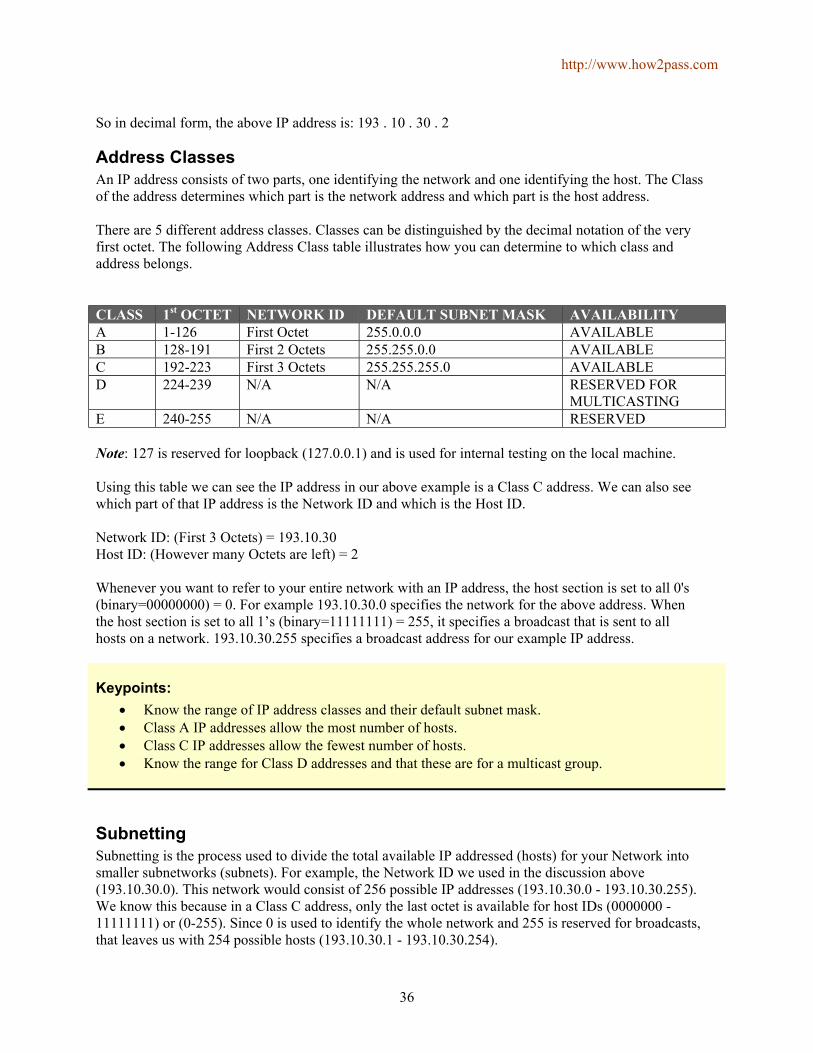
http://www.how2pass.com
36
So in decimal form, the above IP address is: 193 . 10 . 30 . 2
Address Classes An IP address consists of two parts, one identifying the network and one identifying the host. The Class of the address determines which part is the network address and which part is the host address. There are 5 different address classes. Classes can be distinguished by the decimal notation of the very first octet. The following Address Class table illustrates how you can determine to which class and address belongs. CLASS 1st OCTET NETWORK ID DEFAULT SUBNET MASK AVAILABILITY A 1-126 First Octet 255.0.0.0 AVAILABLE B 128-191 First 2 Octets 255.255.0.0 AVAILABLE C 192-223 First 3 Octets 255.255.255.0 AVAILABLE D 224-239 N/A N/A RESERVED FOR
MULTICASTING E 240-255 N/A N/A RESERVED Note: 127 is reserved for loopback (127.0.0.1) and is used for internal testing on the local machine. Using this table we can see the IP address in our above example is a Class C address. We can also see which part of that IP address is the Network ID and which is the Host ID. Network ID: (First 3 Octets) = 193.10.30 Host ID: (However many Octets are left) = 2 Whenever you want to refer to your entire network with an IP address, the host section is set to all 0's (binary=00000000) = 0. For example 193.10.30.0 specifies the network for the above address. When the host section is set to all 1’s (binary=11111111) = 255, it specifies a broadcast that is sent to all hosts on a network. 193.10.30.255 specifies a broadcast address for our example IP address.
Keypoints: • Know the range of IP address classes and their default subnet mask. • Class A IP addresses allow the most number of hosts. • Class C IP addresses allow the fewest number of hosts. • Know the range for Class D addresses and that these are for a multicast group.
Subnetting Subnetting is the process used to divide the total available IP addressed (hosts) for your Network into smaller subnetworks (subnets). For example, the Network ID we used in the discussion above (193.10.30.0). This network would consist of 256 possible IP addresses (193.10.30.0 - 193.10.30.255). We know this because in a Class C address, only the last octet is available for host IDs (0000000 - 11111111) or (0-255). Since 0 is used to identify the whole network and 255 is reserved for broadcasts, that leaves us with 254 possible hosts (193.10.30.1 - 193.10.30.254).

http://www.how2pass.com
37
Suppose we wanted to divide those 254 addresses up into 6 smaller subnets. This can be done by using what is referred to as a Subnet Mask. By looking at the above table we can see Class C addresses all have a default subnet mask of 255.255.255.0. Since the last octet of the subnet mask is 0, it means that the host IDs have not been subdivide into smaller subnets. However, if we choose to divide our network into a few smaller segments (subnets), then we would change the default subnet mask by replacing the last octet with one of the valid subnet masks. On the exam you will be asked to calculate subnet masks, valid ranges within a subnet, number of subnets possible and number of hosts possible. If you memorize the 2 tables below, you should have no problem answering any of these questions.
Class B Addresses
# of bits Subnet Mask Subnets Host Range 2 255.255.192.0 2 16,382 64 3 255.255.224.0 6 8190 32 4 255.255.240.0 14 4094 16 5 255.255.248.0 30 2046 8 6 255.255.252.0 62 1022 4 7 255.255.254.0 126 510 2 8 255.255.255.0 254 254 1 9 255.255.255.128 510 126 128 10 255.255.255.192 1022 62 64 11 255.255.255.224 2046 30 32 12 255.255.255.240 4094 14 16 13 255.255.255.248 8190 6 8 14 255.255.255.252 16,382 2 4
Class C Addresses
# of bits Subnet Mask Subnets Host Range 2 255.255.255.192 2 62 64 3 255.255.255.224 6 30 32 4 255.255.255.240 14 14 16 5 255.255.255.248 30 6 8 6 255.255.255.252 62 2 4
Here’s how it works. QUESTION: If you have a class B IP network with a 10-bit subnet mask, how many subnets and hosts can you have? ANSWER: 1022 subnets with 62 hosts (just look on the table for this answer) QUESTION: You have an IP address of 172.16.13.5 with a subnet mask of 255.255.255.128. What is your network ID and what range is the range of addresses in this subnet. ANSWER: Network ID is 172.16.13.0, range is 172.16.13.1 - 172.16.13.126 (Since you are subnetting all 8-bits in the 3rd octet, the number in the 3rd octet becomes part of your

http://www.how2pass.com
38
network ID. By looking at the table you see you have 126 hosts in each subnet. You also see the address range for each subnet is 128. Since the 0 is you network address and 127 is your broadcast address, the valid range of hosts addresses in this subnet is 172.16.13.1 - 172.16.13.126 = 126). QUESTION: You have a subnet mask of 255.255.255.248 in a class B network. How many subnets and hosts do you have? ANSWER: 8190 subnets, each with 6 hosts. QUESTION: If you have a Class C network with a 6-bit subnet mask, how many subnets and hosts do you have? ANSWER: 62 subnets, each with 2 hosts. QUESTION: You have an IP address of 172.16.3.57 with an 11-bit subnet mask. What is the Network ID, range of subnet addresses, and Broadcast address for this subnet? ANSWER: Network ID = 172.16.3.32 = 1
Host Ids = 172.16.3.33 - 172.16.3.62 = 30 Broadcast Address = 172.16.3.63 = 1
32
By looking at the table above, you can see that a class B address with an 11 bit subnet mask has a RANGE of 32 with 30 HOSTS. Since this is a class B address we know that the first 2 octets are the original Network ID (172.16.0.0). Since we are subnetting all 8-bits of the 3rd octet, then the 3rd octet automatically becomes part of our Subnetwork ID (172.16.3). We know by the table that an 11-bit subnet mask will have 30 hosts and 32 addresses in each range. Since we are subnetting more than 8- bits, the four octet of our subnet will always begin with 0. So the first 32 IP address available to us in 172.16.3 are 172.16.3.0 - 172.16.3.31. Our given IP address (172.16.3.57) is not in this range. The next range of 32 IP addresses is 172.16.2.32 - 172.16.3.63. Bingo…This is the subnet we are looking for. We know that the first address in the subnet range is always the Network ID (172.16.3.32). The next 30 are all valid hosts (172.16.3.33 - 172.16.3.62). The remaining address (172.16.3.63) is our broadcast address. QUESTION: You have a class C network address of 192.158.17.0. You need the largest possible number of subnets with up to 12 hosts on each. Which subnet mask would you use? ANSWER: 255.255.255.240 (look at the table) QUESTION: You have a Network ID of 172.191.0.0. with 8 subnets. You need to allow for the largest possible number of hosts per subnet. Which subnet mask would you use? ANSWER: 255.255.240.0 (look at the table)
Private IP Addresses Following ranges of IP addresses are considered as Private Networks by RFC 1918. You can use these IP addresses privately within you own Intranet.
• 10.0.0.0 – 10.255.255.255
http://www.how2pass.com
39
• 172.16.0.0 – 172.31.255.255 • 192.168.0.0 – 192.168.255.255
Keypoints: • We highly recommend you quickly draw the above IP tables when you first enter the testing
room. • You are going to have to know this information. For the Class B table, the key is to memorize the
first two columns (# of bits and subnet mask). For the 3rd column (Subnets), you just have to memorize the “2” in the first row. After that you can just use the formula (previous number x 2 + 2 = next entry). For example, the next row would be 2 x 2 + 2 = 6. The fourth column is easy, it is just the inverse or opposite of the 3rd column. Turn the 3rd column upside down and you have the forth column. The fifth column (Range) is pretty easy also. Just remember that the first row is “64”. Then as you go down the column use the formula (previous number divided by 2) until you get to the ”1”. Then start over again with “128” and divide by 2 again as you go down the column.
• Know that 6 bits of subnetting is the most you can have with a class C address. • Know the three ranges of Private IP Addresses above. • Know that it is the subnet mask that actually determines what part of the IP address that is the
Network Number and what part is the Host Node.
Enabling IP Routing IP routing is enabled by default on Cisco routers. To enable IP on an interface, you have to be in the interface configuration mode:
Router(config-if)# ip address <IP address><Subnet Mask> Add static IP routes with:
ip route <network> <mask> <address | interface > <admin distance> ip default-network <network>
The following commands can be used to monitor you IP information:
show ip protocol show ip route show ip interface
Keypoints: • IP routing is enabled by default on the Cisco routers. • Enable IP on an interface by assigning an IP address to that interface as demonstrated above. • Know how to configure an IP static route. • You can display an interface IP address by issuing the “show ip interface” command. • Know which IP addresses can be used for.

http://www.how2pass.com
40
Configuring IP addresses To configure an IP address you have to enter the following command at the interface config prompt:
Router(config-if)# ip address <IP address> <subnet mask>
Verifying IP addresses IP addresses can be verified by either using Telnet, ping, or trace. Telnet Verifies the application-layer software between source and destination stations. This is the most complete test mechanism available. Ping Uses the ICMP protocol to verify the hardware connection at the logical address of the network layer. Trace Uses Time-To-Live (TTL) values to generate messages from each router used along the path. This is very powerful in its ability to locate failures in the path from the source to the destination.
Keypoints: • Ping, Telnet and Trace can all be used to verify network connectivity. This is accomplished by
typing • the command followed by the complete IP address or host name. • Ping operates at the network layer. • Know that the ping command uses the echo request/echo reply as its most common request/reply
pair. • You can use the ping command in the USER and Privileged modes.
TCP/IP transport layer protocols TCP/IP uses the DOD Model which is:
TCP/IP (DOD) Model Layers OSI Model Layers Process Application - Maps to Application, Presentation, Session Host to Host - Maps to Transport Internet - Maps to Network Network Access - Maps to Data Link and Physical
Transport Layer (OSI) or Host to Host (DOD) protocols use TCP and UDP. Transmission Control Protocol TCP is a connection oriented transport layer protocol with built in reliability. Takes large blocks of data and breaks it down into segments. It numbers and sequences each segment so the destination’s TCP protocol can re-assemble back into the original order. TCP uses acknowledgement via sliding windows. Has a large overhead due to built in error checking. This protocol uses Port 6.

http://www.how2pass.com
41
User Datagram Protocol UDP is a connectionless oriented transport protocol for use when the upper layers provide errorrecovery and reliability. UDP does not sequence data or re-assemble it into any order after transmission. This protocol uses Port 17.
TCP/IP network layer protocols Network Layer (OSI) or Internet (DOD) protocols are IP, ARP, RARP, BOOTP, and ICMP. Internet protocol IP provides routing and a single interface to the upper layers. No upper layer protocol and no lower layer protocol have any functions relating to routing. IP receives segments from the transport layer and fragments them into packets including the host’s IP address. Address Resolution Protocol ARP is responsible for resolving IP addresses to MAC addresses. It stores these in its arp cache for later use. It does this to inform a lower layer of the destination’s MAC address. Reverse Address Resolution Protocol RARP resolves MAC addresses to IP addresses on diskless workstations. Boot Strap Protocol BootP is used also for diskless workstations when it requires an IP address. Internet Control Message Protocol ICMP is a management protocol and messaging service provider for IP. Its messages are carried as IP datagrams. ICMP is used in to perform the following functions:
• Destination Unreachable - If a router cannot send an IP packet any further it uses an ICMP echo to send a message back to the sender notifying it that the remote node is unreachable.
• Buffer Full - If a routers memory buffer is full ICMP will send out a message to the originator. • Hops - Each IP datagram is assigned a path. This consists of hops. If it goes through the
maximum number of hops the packet is discarded and the discarding router sends an ICMP echo to the host.
• Ping - Ping uses ICMP echo messages to check connectivity.

http://www.how2pass.com
42
Keypoints: • Know the above 4 functions of ICMP. • ICMP commands can be executed from USER EXEC and PRIVILEGED EXEC modes. • TCP/IP networks use ARP requests to determine a destination’s MAC address. • ICMP is implemented by all TCP/IP hosts. • TCP is a reliable connection oriented protocol that acknowledges receipt of packets. • Know that all reliable connections use acknowledgments. • Know that Reverse ARP (RARP) maps Ethernet addresses to IP address and is implemented at
the data link layer.
http://www.how2pass.com
43
Routing Protocols Routers can be used to segment networks by routing between two or more interfaces. Broadcasts will be filtered and the packets will be routed based upon the destination network address (IP or IPX). Routing protocols such as RIP, IGRP, OSPF, etc. are used to route information between routers. These differ from Routed protocols such as TCP/IP, IPX, AppleTalk, etc.
Multiprotocol Routing There are 2 types of multiprotocol routing: Separate A multiprotocol routing environment in which each protocol is not aware of the other protocols on the same router. RIP and OSPF are separate routing protocols. Integrated A multiprotocol routing environment where each protocol is aware of the other protocols and they share the results of the routing algorithm. EIGRP is an integrated routing protocol that integrates support for IP, AppleTalk and IPX using a distance vector algorithm based on IGRP.
Distance Vector Concept Distance vector based routing algorithms pass periodic copies of a routing table from router to router. Regular updates between routers communicate topology changes. Each router receives a routing table from its direct neighbor and increments all learned routes by one. This is the way that the algorithm learns the internetwork topology, via second hand information. Distance Vector algorithms do not allow a router to know the exact topology of an internetwork. RIP and IGRP are Distance Vector Routing Protocols. Distance Vector Topology Changes When the topology in a distance vector network changes, routing table updates must occur. As with the network discovery process, topology change notification must occur router to router. Distance Vector protocols call for each router to send its entire routing table to each of its adjacent neighbors. When a router receives an update from a neighboring router, it compares the update to its own routing table. If it learns about a better route (smaller hop count) to a network from its neighbor, the router updates its own routing table. Problems with Distance Vector Distance Vector routing protocols are prone to Routing Loops and counting to infinity. Routing loops can occur if the internetwork’s slow convergence on a new configuration causes inconsistent routing entries. Counting to infinity continuously loops packets around the network, despite the fundamental fact that the destination network is down. To over come these you can implement several different options:

http://www.how2pass.com
44
• Defining a maximum number of hops - Specify a maximum distance vector metric as infinity.
16 with RIP and 256 with IGRP. • Split Horizon - If you learn a protocol’s route on an interface, do not send information about that
route back out that interface. • Route Poisoning - Information past out on an interface is marked as unreachable by setting the
hop count to 16 for RIP • Hold Down Timers - Routers ignore network update information for some period of time. The
timers can been reset when:
1. The timer expires. 2. Infinity is finally defined as some maximum number. 3. Another update is received indicating that the original route to the network has been
restored.
Keypoints: • Know the 4 ways to reduce routing loops (listed above) and what they mean. • Know there are 2 types of routing table entries 1) Permanent and 2) Temporary.
Link State Concepts The Link State Routing algorithm maintains a more complex table of topology information. Routers using a link state routing protocol have a complete understanding and view of the entire network. The Link State algorithm uses Link State Packets (LSP) to inform other routers of distant links. All routers exchange LSP to build a total view of the network. OSPF is a Link State Routing Protocol. When the topology changes, the first routers to find out sends LSP to all other routers on the internetwork. All routers then re-calculate the best path to any affected route. Link State routing protocols are more intensive in terms of power, memory, and bandwidth required. Problems with Link State Link-state (OSPF) needs lots of processing power to rebuild the routing database (tree). Network bandwidth, is another problem. Link-state info can flood the network.
Differences between Distance Vector and Link State • Distance Vector gets all its information second hand or gossip whereas link state routing obtains a
total topology of the internetwork. • Distance Vector determines the best path by counting hops. Links State uses a complex
bandwidth analysis. • Distance Vector updates topology changes every 30 seconds as default which causes a slow

http://www.how2pass.com
45
• convergence time. Link State can be triggered by topology changes resulting in faster convergence times.
• Link state is harder to setup.
Keypoints: • Routers can learn hops dynamically by receiving periodic updates from other routers, or by
default routes. • Know the differences between Distance Vector and Link State protocols.
RIP RIP is a distance vector routing protocol that uses hop count as its metric. The maximum hop count is 15 so 16 hops is deemed unreachable. RIP updates are broadcast every 30 seconds by default. RIP is enabled by typing:
Router(config)# router rip
This puts you in router configuration mode. You then have to associate attached networks with the RIP process. You only associate directly attached networks.
Router(config-router)# network <network id>
Keypoints: • The “network” command is used in router configuration mode to enable directly connected
networks to be used by RIP. • RIP is capable of load sharing over multiple paths and it broadcasts updates every 30 seconds. • Know that the “router rip” command is the first command you issue when you are getting ready
to configure RIP. • Know that the “router rip” command is issued in the Router(config)# mode. • Know that in order to enable RIP you must 1) specify the routing protocol and 2) specify directly
connected networks.
IGRP IGRP is a distance vector routing protocol designed by Cisco. The maximum hop count is 255 and it uses a combination of variables to determine a composite metric.
• Bandwidth • Delay • Load

http://www.how2pass.com
46
• Reliability • Maximum Transmission Unit (MTU)
IGRP is enabled by typing:
Router# router igrp 12 Where 12 is the autonomous system number. You then have to associate directly connected networks in the same way as you did with RIP.
network <network id>
Keypoints: • Enable IGRP routing by using the “router igrp <autonomous system #>” command. • IGRP supports up to 4 paths by default, but can support up to 8. • In any IGRP route path, the next hop router must be closer to the destination router than to the
local router. • IGRP broadcasts routing updates every 90 seconds.

http://www.how2pass.com
47
Network Security
Access Lists Access lists are a list of conditions that control access to a router’s interface.
• Each packet is compared with each line of the access list in sequential order. • Once a match is made it is acted upon and no further comparisons take place. • There is an implicit deny at the end of each access list.
Access List Numbers to Know
1-99 - IP Standard Access Lists 100-199 - IP Extended Access Lists 800-899 - IPX Standard Access Lists 900-999 - IPX Extended Access Lists 1000-1099 - IPX SAP Access List
Standard IP Access List A standard IP access list analyses the source address of the packet and matches it against the access list. To create an access list in global configuration mode:
Router(config)# access-list <number 1-99> <permit or deny> <source address> <wildcard mask>
Wildcard Mask A wildcard mask is 32 bit, 4 octet, address that can be used on a router to allow you to apply an access list to a specific IP address or a specific range of IP addresses. Here is how it works: Let say you want to apply an access list 100 to all hosts in the 172.30.0.0 network. Your input on the router would look like this:
Router(config)# access-list 100 permit 172.30.0.0 0.0.255.255 The wildcard mask will be converted to binary 00000000.00000000.11111111.11111111. A “0” bit tells the router to compare that position of the packets IP address to the source address 172.30.0.0 to see if it matches. If all the “0” bits match, it will apply the access list. If it doesn’t, the access list will not be applied to this packet. A “1” bit in the wildcard mask tells the router to ignore this bit of the packets IP address. So all 8 bits of octet 1 (172) and all 8 bits of octet 2 (30) will be compared to any incoming packet. The last 2 octets of the packet are ignored. Therefore any packet beginning with 172.30 will have the access list applied. Now if you wanted to check only IP addresses in subnets 172.30.16.0 to 172.30.31.0, you would have to manipulate the bits in the wildcard mask to only check the bits unique to those subnets. To check for only a specific address, you would enter a wildcard mask of 0.0.0.0. This means that every bit of the IP address will be compared to the source IP address you entered for the access list. Example: access-list 100 permit 172.30.16.100 0.0.0.0 This will only apply to packets from host 172.30.16.100.

http://www.how2pass.com
48
You apply the access list to an interface by entering the interface configuration mode and typing.
Router(config-if)# <protocol> access-group <list number> <out/in> This applies the access list to all traffic on the selected interface. Out means packets leaving the interface and in means packets entering the interface. Extended IP Access Lists Extended IP access lists operate the same as standard IP access lists but they use the number from 100- 199 instead of 1-99. Also more options are available instead of only checking the source address. You can now specify:
• Source Address • Destination Address • IP Protocol (TCP, UDP, ICMP etc…) • Port Information (www, DNS, ftp, etc..)
Access-list <number 100-199> <permit or deny> <protocol> <source address> <destination address> <operator> <port>
Example: access-list 100 deny tcp 172.18.16.0 0.0.0.255 any eq ftp The above example will deny any ftp traffic from 172.18.16.x to any destination address. ANY can be used to specify any source or destination address which is the same as 0.0.0.0 255.255.255.255. HOST can be used to specify a host. Host 172.18.16.2 is the same as 172.18.16.2 0.0.0.0. Extended IP access lists are applied to an interface in the same way as standard IP access lists.
show access-lists Displays all access lists running on the router. show ip access-lists Displays all IP access lists running on the router. show ip int Shows the IP interface information and indicates any Outbound or
inbound access lists.
sh run Shows the running config and any access lists that are globally set up and to which interfaces.
Keypoints: • To display the contents of a particular access list, you would use the “show access-list listnumber
command. • To display the contents of all access lists, you would just enter the “show access-lists” command
without specifying a number. • Know that you should place Standard IP access lists close to the destination router, but that you
place Extended IP access lists close to the source router. • You can display your access lists by using the “show access-lists” or “show running-config”
commands.

http://www.how2pass.com
49
Standard IPX Access Lists Standard IPX access lists permit or deny packets based upon the source and destination IPX addresses. This differs from IP where it only looks at the source address. There are no wildcard masks with IPX and you can use either the Node Address or Network Address.
Router(config)# access-list 810 permit 4b 5c The above line will only allow packets from network 4b to reach network 5c. These are applied in a similar way to IP from the interface config mode:
Router(config-if)# ipx access-group 810 out Extended IPX Access Lists Extended IPX Access Lists can filter based upon:
• Source Network/Node • Destination Network/Node • Protocol (IP, TCP, UDP, SPX etc) • Protocol Port number (socket)
access-list <number 900-999> <permit/deny> <protocol> <source address> <socket> <destination address> <socket>
Keypoints: • If you do not enter the argument “in” or “out” at the end of the access-group command, then
“out” is assumed. • You can use the “show interface” command to see if an access list has been enabled on a
particular interface. • The 2 steps to configure and apply a standard access list to an interface are
1. define the access list and its parameters, 2. enable an interface to become part of the access list group.

http://www.how2pass.com
50
WAN Protocols
Connection Terms Customer Premises Equipment (CPE) Devices physically located at the WAN subscribers premises. Includes both owned and leased devices. Central Office (CO) A switching facility that provides the nearest point of presence for a providers WAN service. Demarcation (Demarc) The point at which the CPE ends and the local loop portion of the service begins. Usually the telecommunications closet at the subscriber’s location. Local Loop Cabling that extends from the Demarc to the CO. Data Terminal Equipment (DTE) Usually the router where the packet switching application resides. Date Circuit-terminating Equipment (DCE) The device used to convert the user data from the DTE into an acceptable WAN protocol. This usually consists of a DSU/CSU device, modem, or NT1 device.
Keypoints: • Know the definitions of the connection terms listed above.
Frame Relay Frame relay is a fast WAN protocol that operates at the Physical and Data Link layers (mostly Data Link layer) of the OSI model. Works between DTE and DCE devices. Uses Packet Switching. DTE consists of terminals, PC’s, routers and bridges, all of which are customer owned end node devices. DCE devices such as packet switchers are owned by the service provider. Frame Relay uses Permanent Virtual Circuits (PVCs). The connection is identified by a Data Link Connection Identifier (DLCI). Frame Relay offers a speeds between 56 Kbps and 2,078 Mbps. However, the default setting for a serial DCE interface is T1. Frame Relay uses a CRC, bad packets are discarded and the receiving station requests re-transmission of any missing frames. Data Link Connection Identifiers (DLCI) Used to identify the virtual circuits. DLCIs can be set to a number between 16 and 1007. Local Management Interfaces (LMI) Provide information about the DLCI values and the status of virtual circuits. The default is Cisco but there are 3 possible settings:
• Cisco (Default)

http://www.how2pass.com
51
• ANSI • Q933a
To set up frame relay on an interface just set the encapsulation to frame-relay. Frame relay encapsulation can either be Cisco (Default) or IETF. You must use Cisco encapsulation to connect two Cisco routers or IETF if a third party router is involved. Frame Relay configuration is done in the interface configuration mode. Although LMI type is configurable, the Cisco router will try to autosense which LMI type the switch is using.
Router(config-if)# encapsulation frame-relay <cisco or ietf> To assign a DLCI to an interface you would type.
Router(config-if)# frame-relay interface-dlci <number 16-1007> To set the LMI type you enter:
Router(config-if)# frame-relay lmi-type <cisco/ansi/q933a> A keepalive interval must be set to enable LMI on an interface. This is 10 seconds by default and can be set by typing:
Router(config-if)# frame-relay keepalive <number of seconds>
The Frame Relay Map tells the network protocol how to get from a specific protocol and address pair to the correct DLCI. There are two ways to make this happen, you can use the frame-relay map command or you can use the inverse-arp function. The “frame-relay map” command can be used to show which routers are reachable.
Router(config-if)# frame-relay inverse-arp <protocol> <dlci> Router(config-if)# frame-relay map <protocol> <protocol address> <dlci> broadcast <cisco or ietf>
With frame-relay you can use subinterfaces to allow multiple virtual circuits on a single serial interface and each subinterface can be treated as a separate interface. You use the interface s0.interface number command:
Router(config-if)# interface s0.<subinterface number> <point-to-point or multipoint> You can configure subinterfaces to support the following connection types: Point-to-point A single subinterface is used to establish one PVC connection to another physical interface on a remote router. Each interface would be on the same subnet and have a single DLCI. Each point-to-point connection is its own subnet and act like a leased line. Multipoint A single subinterface is used to establish multiple PVC connections to multiple physical interfaces on a remote router. All participating interfaces are in the same subnet and each interface would have it’s own DLCI. The subinterface acts like a NBMA network and broadcasts are subject to split horizon

http://www.how2pass.com
52
rules. It is worthwhile creating a subinterface with a number that matches the DLCI identifier. Committed Information Rate (CIR) The rate, in bits per second, at which the Frame Relay switch agrees to transfer data.
Keypoints: • DLCIs are used to distinguish between PVCs. • Frame Relay operates at the Data Link and Physical layers. • You can use the “show interface” command to display the LMIs and DLCIs on a frame relay
enabled interface. • The default bandwidth setting for a serial DCE interface is T1 (1.544 Mbps). • Know what command is used to configure a subinterface. • Know that multipoint specifies that a frame relay subinterface is configured as a single subnet. • LMI type is autosensed. • You must configure static maps if a Frame Relay router does not support Inverse ARP. • You must remove any network address assigned to an interface and configure the local DLCI
when creating a Frame Relay subinterface. • Know the definition of CIR. • Know how subinterfaces are numbered.
Monitoring Frame Relay
show frame-relay ip - Shows frame relay ip statistics show frame-relay lmi - Shows LMI statistics show frame-relay map - Shows map table show frame-relay pvc - Shows PVC Statistics Also DLCI Info show frame-relay route - Shows frame relay routes show frame-relay traffic - Shows protocol statistics
The Show Interface command also shows Frame Relay information on a specific interface. The show ip route command will also show which routers are reachable.
Keypoints: • The “show frame-relay map” or “show ip route” commands can be used to show which IP routers
are reachable. • Use the “show frame-relay pvc” command to display DLCI info. • Use the “show frame-relay lmi” command to view LMI traffic statistics.

http://www.how2pass.com
53
ISDN Integrated Services Digital Network (ISDN) is a digital service designed to run over existing telephone networks. ISDN can support both data and voice simultaneously. ISDN encompasses the OSI Physical, Data Link, and Network Layers. ISDN networking can provide up to 128 Kbps with a PPP Multilink connection to corporate networks or the Internet. A Basic Rate Interface (BRI) connection can also be used as a backup line in case the primary link goes down. In this case you have to set the desirability of the ISDN link to be very low. In other words only use if there is no other way. ISDN has the following benefits over standard telephone connections:
1. Data transfer is faster than typical modems 2. Call setup is faster 3. ISDN can carry voice, video, and data traffic
ISDN Protocols These protocols deal with ISDN issues:
• E – Specifies ISDN on the existing telephone network. • I – Specifies Concepts, terminology, and Services. • Q – Specifies switching and signaling.
Keypoints: • Your router will always be connected by the U interface into NT1. • The BRI interface on your router is considered Terminal Equipment type 1 (TE1). • Know the 3 benefits of ISDN over standard telephone service. • The ISDN “Q” protocol specifies the type of switch that the router communicates with. • Know that ISDN provide integrated voice and data capability. • Know that ISDN standards define the hardware and call setup schemes for end-to-end digital
connectivity. • Know the Benefits for ISDN listed above.
ISDN Function Groups Devices connected to the ISDN network are known as terminals and have the following types:
• TE1 – Terminal Equipment type 1 understands ISDN standards. Like a BRI Interface on a router. • TE2 – Terminal Equipment type 2 predates ISDN standards. To use a TE2, you must have a
Terminal Adapter (TA).

http://www.how2pass.com
54
ISDN Reference Points ISDN uses four different reference points to define logical interfaces. They are as follows:
• R – Defines the reference point between non ISDN equipment and a TA • S – Defines the reference point between user terminals and an NT2 • T – Defines the reference point between NT1 and NT2 devices • U – Defines the reference point between NT1 devices and Line Termination Equipment. (North
America Only)
ISDN Benefits 1. Full-time connectivity is spoofed on routers using DDR 2. SOHO sites can be cheaply supported 3. Can be used as a backup for leased lines 4. Modem racking can be eliminated by using modem cards.
ISDN Channels ISDN can either be Basic Rate ISDN (BRI) or Primary Rate ISDN (PRI). BRI is 2 64 Kbps B Channels for data and one 16 Kbps D Channel for link management and connects to NT1 for 4-wire connection. PRI is 23 B Channels and 1 D Channel in the US or 30 B Channel and 1 D Channel in Europe. Occasionally when configuring ISDN you will need to configure a Service Profile ID (SPID). A SPID is a series of characters which can look like phone numbers. These numbers will identify your connection to the Switch at the CO. The SPIDs are processed during each call setup operation.
Keypoints: • Total bandwidth for a BRI connection is 144 Kbps (64+64+16) and connects to NT1 for 4-wire
connection. • A SPID is a series of characters that identifies you to a switch at the CO. • A Terminal Adapter (TA) device is required to connect a V.35 interface to a BRI port.
Cisco’s ISDN Implementation Cisco implements BRI using a BRI RJ45 interface on a router enabled as a TE1 device.
HDLC The High Level Data Link Control Protocol is a link layer protocol that is the standard encapsulation type for Cisco Serial interfaces. It is a bit-oriented synchronous data link layer protocol developed by ISO. Derived from SDLC, HDLC specifies a data encapsulation method on synchronous serial links using frame characters and checksums.

http://www.how2pass.com
55
PPP Point-to-Point Protocol. A successor to SLIP, PPP provides router-to-router and host-to-network connections over synchronous and asynchronous circuits. This data link protocol can be used over either asynchronous (dial-up) or synchronous (ISDN) media. It uses the Link Control protocol (LCP) to maintain the data link. It has a number of features, including Authentication using either PAP or CHAP and compression. PPP can actually use the 4 physical interfaces:
• Asynchronous Serial • Synchronous Serial • HSSI • ISDN
PPP is enabled at the Interface configuration mode by typing:
Router(config-if)# encapsulation ppp There are then several sub PPP commands such as authentication, multilink, compression, and callback. The Show Interface command lists the encapsulation method on an interface. Also Show Running- config displays the PPP commands allocated to an interface.
Keypoints: • PPP compression is handled by the Link Control Protocol (LCP). • Network Control Program (NCP) is the PPP service that supports multiple network layer
protocols. • LAPD protocol is based on the HDLC protocol. • PPP can be used over DDR or ISDN interfaces. • Know that HDLC and PPP support multiple upper layer protocols and are the most commonly
used • ISDN encapsulation methods. • To display the encapsulation type used on an interface, you would use the “show interface”
command. • PPP provides router-to-router and host-to-network connections over synchronous and
asynchronous interfaces.
----- Copyrights © 2003 – How2pass.com -----