Embed Size (px)
Citation preview
Revision: 1.03
Technical manual Date: Feb 10, 15
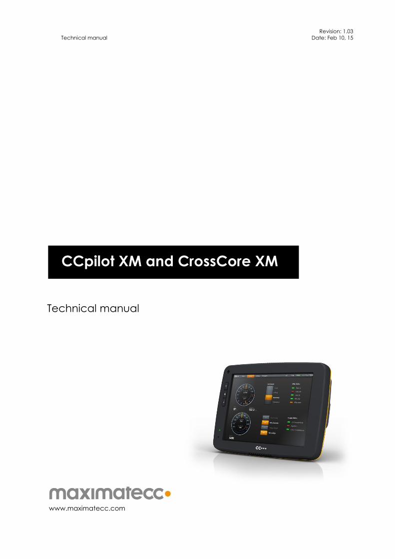
Technical manual
www.maximatecc.com
CCpilot XM and CrossCore XM

CCpilot XM - Technical Manual
Date: Feb 10, 15
www.maximatecc.com
Contents
Contents .............................................................................................................................................2
1. Introduction ................................................................................................................................4
1.1. Product models .......................................................................................................................... 4
1.2. Conventions and definitions ................................................................................................... 5
1.3. Identification .............................................................................................................................. 5
1.4. Care ............................................................................................................................................. 5
1.5. Environment and Environmental Tolerance ......................................................................... 6
1.6. Cleaning ...................................................................................................................................... 6
2. Overview ....................................................................................................................................7
1.7. Front side ..................................................................................................................................... 7
1.8. Rear side ...................................................................................................................................... 7
3. Installation ..................................................................................................................................8
1.9. Installing the SIM card ............................................................................................................... 8
1.10. Connecting to power supply .......................................................................................... 8
1.11. Mounting ............................................................................................................................. 9
1.12. Environmental considerations ....................................................................................... 10
1.13. Cables................................................................................................................................ 10
1.14. Antennas ........................................................................................................................... 10
4. Basic operations ......................................................................................................................11
1.15. Starting Up ......................................................................................................................... 11
1.16. Turning off .......................................................................................................................... 11
1.17. Adjusting the screen brightness .................................................................................... 12
1.18. Using the touch screen ................................................................................................... 12
1.19. Status LED indicators ....................................................................................................... 12
1.20. Clock back-up battery ................................................................................................... 12
5. Interface overview ..................................................................................................................13
1.21. Storage memory .............................................................................................................. 13
1.22. Light sensor ....................................................................................................................... 13
1.23. Buzzer ................................................................................................................................. 13
1.24. Audio output & input ...................................................................................................... 13
1.25. Video.................................................................................................................................. 13
1.26. CAN .................................................................................................................................... 14
1.27. USB ...................................................................................................................................... 14
1.28. Ethernet ............................................................................................................................. 14
1.29. Serial port .......................................................................................................................... 14
1.30. Digital inputs ..................................................................................................................... 14
1.31. GPS ..................................................................................................................................... 14
1.32. GPRS/GSM ........................................................................................................................ 15
1.33. WLAN ................................................................................................................................. 15
1.34. Bluetooth ........................................................................................................................... 15
6. Connectors ...............................................................................................................................16
1.35. Connector layout ............................................................................................................ 16
7. Specifications...........................................................................................................................20
CCpilot XM - Technical Manual
Date: Feb 10, 15
www.maximatecc.com
1.36. Standard models connectivity level ............................................................................ 20
1.37. Technical data ................................................................................................................. 20
1.38. Environmental tolerance ............................................................................................... 22
1.39. Weight and dimensions .................................................................................................. 23
8. Technical Support ....................................................................................................................25
9. Trade Mark, etc. ......................................................................................................................26
10. Index .........................................................................................................................................27
CCpilot XM - Technical Manual
Date: Feb 10, 15
www.maximatecc.com
1. Introduction
CCpilot XM and CrossCore XM family is a PC-based on-board display computer and controller with
a rich set of integrated functions. With its powerful Intel Atom CPU with Windows or Linux it is an
open platform that facilitates easy implementation of premium user interaction, reliable controls
and integrated fleet management.
This technical manual and reference handbook provides important information regarding the
hardware and basic usage. For software and operating system specifics please see additional
documentation.
1.1. Product models
This documentation is applicable for both CCpilot XM and CrossCore XM. They are offer the same
level of hardware and interfaces, with the following difference:
CCpilot XM is the display version, available in several screen sizes.
CrossCore XM offers the same features and high performance as CCpilot XM but without
the display.
CCpilot XM and CrossCore XM is available in two product models, the standard and the CCpilot
All-integrated
The standard model offers integrated functions and interfaces such as CAN, USB, Ethernet,
Audio and Video.
The All-Integrated model provides, in addition to the standard features, wireless interfaces
such as GPRS, WLAN and Bluetooth as well as GPS for positioning.
The platform also enables customization of hardware and software. Described herein are the
possibilities which can be obtained using above product models, additional features are described
in model specific documentation.
CCpilot XM - Technical Manual
Date: Feb 10, 15
www.maximatecc.com
1.2. Conventions and definitions
CCpilot XM and CrossCore XM are in most cases identical in functionality and usage. The following
definition is used to separate unit specific details. The observe symbol is also used to highlight such
difference.
Defines Use
CCpilot XM Information that is specific for CCpilot XM
CrossCore XM Information that is specific for CrossCore XM
XM device Information that applies to both CCpilot XM and CrossCore XM
The observe symbol is used to highligt information in this document, such as differences between
product CCpilot and CrossCore product models.
The A symbol is used to highlight information specific for CCpilot XM All-Integrated.
The exclamation symbol is used to highlight important information.
Text formats used in this document.
Format Use
Italics Paths, filenames, definitions.
Bold Command names and important information
1.3. Identification
On the side of the XM device there is a label containing version and serial numbers which identify
your unique computer. Take note of them. During service and other contact with the supplier it is
important to be able to provide these numbers.
1.4. Care
During welding or other service on the machine, all cables to the XM device shall be
disconnected.
Serviced shall only be made by authorised personnel. If the unit is opened by unauthorised
personnel, the guarantee will cease to be valid.
Scratches, or in the worst case damages, to the display occur easily if it comes in contact
with a sharp edge or hard material. In order to increase the longevity of the screen, this is
naturally something which should be avoided.
The Flash memory used for storage is durable; however as with all flash memory types the
write cycles are limited. Avoid unnecessary writing to the flash memory.
If the unit becomes too hot it will operate at a limited speed and can also be damaged.
Therefore, do not cover the unit by covering it, for example hanging a jacket or other
clothes on it.
Consider traffic safety when CCpilot XM is installed and whenever it is used. maximatecc
does not recommend that CCpilot XM or its accessories be used actively by the driver when
a risk of injury to people, or damage to property, is present.
CCpilot XM - Technical Manual
Date: Feb 10, 15
www.maximatecc.com
Be advised that the XM device draws power from the vehicle battery. This can result in the
inability of the vehicle to start if the on-board computer has been on for a period of time
without the vehicle engine running.
1.5. Environment and Environmental Tolerance
The XM device has been designed to cope with tough environmental demands. Strict tests have
been conducted on the unit in order to ensure that it fulfils the expectations of a rugged unit. Much
work has been performed to choose and design internal components so that they, under all
circumstances and in the best possible way, provide you with a dependable and user-friendly
working instrument. Within the chapter Specifications, a list of standards can be found according
to which XM device has been tested and approved.
The XM device is preferably placed in a way that prevents exposure to water contact. It is also
important that it is mounted securely on a stand or the like to inhibit the unit from moving and
thereby becoming damaged, damaging the vehicle and/or people during, for example, a traffic
accident.
1.6. Cleaning
To ensure proper and reliable functionality over time, the unit shall be wiped cleaned of dirt and
dust. Use a suitable light damp rag to clean the unit.
Never use alkaline, alcoholic or other chemicals for cleaning which can damage the unit.
CCpilot XM - Technical Manual
Date: Feb 10, 15
www.maximatecc.com
Light sensor
ON/OFF button
Increase and
decrease the display’s
brightness level
Status indicator
Touch screen
Buzzer
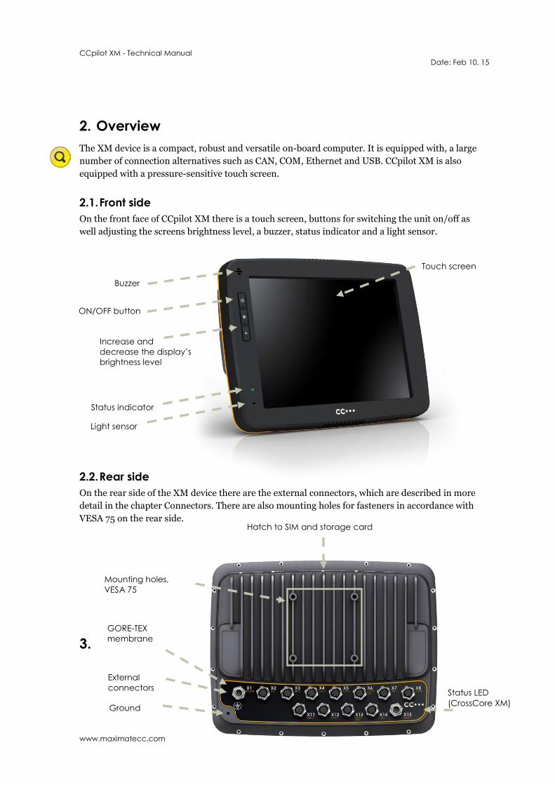
2. Overview
The XM device is a compact, robust and versatile on-board computer. It is equipped with, a large
number of connection alternatives such as CAN, COM, Ethernet and USB. CCpilot XM is also
equipped with a pressure-sensitive touch screen.
2.1. Front side
On the front face of CCpilot XM there is a touch screen, buttons for switching the unit on/off as
well adjusting the screens brightness level, a buzzer, status indicator and a light sensor.
2.2. Rear side
On the rear side of the XM device there are the external connectors, which are described in more
detail in the chapter Connectors. There are also mounting holes for fasteners in accordance with
VESA 75 on the rear side.
3.
Ground
Mounting holes,
VESA 75
GORE-TEX
membrane
External
connectors
Hatch to SIM and storage card
Status LED
(CrossCore XM)

CCpilot XM - Technical Manual
Date: Feb 10, 15
www.maximatecc.com
3. Installation
Install the device in such a way that is considered safe and does not expose any unnecessary stress
to the unit. In this section, some recommendations are made regarding installation.
3.1. Installing the SIM card
Installing the SIM card for the GPRS/GSM functionality requires the hatch on the top of the unit to
be opened. In such case the following preparations and precautions must be obeyed.
Make sure all cables are disconnected from the unit’s connectors
Place the unit on a dry, clean and ESD protected area
Remove the four M3 screws holding the hatch on the top of the unit using a T10 Torx
screwdriver.
Remove the hatch.
Carefully place the SIM card in the SIM card holder. Make sure it slides all the way in and
locks.
Assembly the unit in reverse order. Tighten the four M3 screws with a torque of 0.9 Nm
(0.66 ft-lbs).
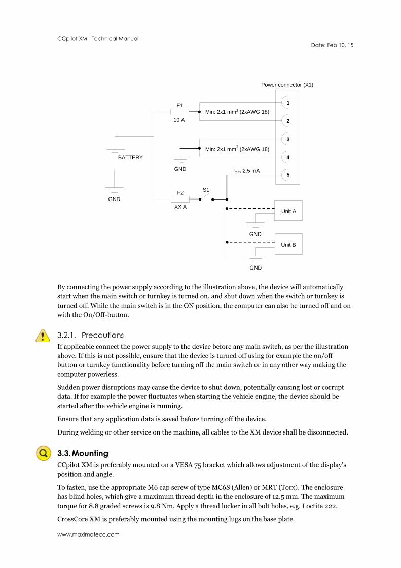
3.2. Connecting to power supply
This instruction address vehicle installations but the principle is the same also for other types of
installations. See also the description of the pin outs for the Power Supply Connector under the
section External interface description.
Carefully follow the connection instructions below. Make sure that all contacts are angled
correctly and that they do not have to be forced, but lock gently and pliant.
GND (pin 3 and 4) is connected to the vehicle’s ground.
Battery (pin 1 and 2), i.e. the computer’s power supply (+24 VDC), should be connected
directly to the vehicle’s battery through 10 A fuses (F1). Wire gauges shall be dimensioned
with respect to cable length, supply voltage etc. Minimum cable area is 2x1 mm2 (2xAWG
18).
The ON/OFF (pin 5), i.e. the computer’s on/off signal is connected via the vehicles turnkey
signal or an external on/off switch (S1). If the vehicle has a main power switch (S1) the
computer shall be connected after it, as in the illustration below. The maximum allowed
input current for the on/off signal is 2.5 mA. The fuse F2 fuse rating and wire gauge shall
be dimensioned for the total switch current.
CCpilot XM - Technical Manual
Date: Feb 10, 15
www.maximatecc.com
By connecting the power supply according to the illustration above, the device will automatically
start when the main switch or turnkey is turned on, and shut down when the switch or turnkey is
turned off. While the main switch is in the ON position, the computer can also be turned off and on
with the On/Off-button.
3.2.1. Precautions
If applicable connect the power supply to the device before any main switch, as per the illustration
above. If this is not possible, ensure that the device is turned off using for example the on/off
button or turnkey functionality before turning off the main switch or in any other way making the
computer powerless.
Sudden power disruptions may cause the device to shut down, potentially causing lost or corrupt
data. If for example the power fluctuates when starting the vehicle engine, the device should be
started after the vehicle engine is running.
Ensure that any application data is saved before turning off the device.
During welding or other service on the machine, all cables to the XM device shall be disconnected.
3.3. Mounting
CCpilot XM is preferably mounted on a VESA 75 bracket which allows adjustment of the display’s
position and angle.
To fasten, use the appropriate M6 cap screw of type MC6S (Allen) or MRT (Torx). The enclosure
has blind holes, which give a maximum thread depth in the enclosure of 12.5 mm. The maximum
torque for 8.8 graded screws is 9.8 Nm. Apply a thread locker in all bolt holes, e.g. Loctite 222.
CrossCore XM is preferably mounted using the mounting lugs on the base plate.
GND
1
2
3
4
F1
10 A
GND
BATTERY
S1
Power connector (X1)
5
Min: 2x1 mm2 (2xAWG 18)
Min: 2x1 mm2 (2xAWG 18)
F2
XX A Unit A
GND
Unit B
GND
Imax 2.5 mA
CCpilot XM - Technical Manual
Date: Feb 10, 15
www.maximatecc.com
Ensure that CrossCore XM is mounted to a smooth, flat surface. Fastening the unit to an uneven
surface may stress the enclosure, damage the outer flange or possibly even flex the circuit board
inside, leading to a premature failure.
Ensure the mounting M8 Allen screws are of grade 8.8 or higher, are clean and dry, and apply
torque of about 25 Nm (18 ft-lbs). Use lock washers.
3.4. Environmental considerations
The device shall be placed in a way that prevents the unit from direct exposure to water.
Use caps on any connectors that do not have attached cables.
On the back side of the unit is a GORE-TEX® membrane located, seen as a small hole. This
membrane must never be faced upwards when the unit is mounted. Be cautious not to
insert any object into this hole since it can puncture the GORE-TEX® membrane, leaving
the unit unprotected from moisture and dust intrusion. If the membrane is punctured the
guarantee is void.
To enable sufficient cooling, the XM device must be installed so that air is able to circulate
around the device, avoid installing the device near hot air vents or the like. There must be
at least 50 mm free distance around the unit.
Loose mounting bolts are the most common reason for excessive vibration. Mounting bolts
may become loose due to improper techniques such as missing lock washers, over
tightening or under tightening. Proper tightening requires clean dry bolts, and a torque
wrench.
When CCpilot XM or any device is installed in a vehicle environment it is important that
the installation is traffic-safe. maximatecc does not recommend that CCpilot XM or its
accessories are used actively by the driver or operator when a risk of injury to people, or
damage to property, is present.
3.5. Cables
Cables shall be installed in such a way that they don’t run any risk of being damaged, pinched or
worn.
Avoid bending and twisting cables
Strain-relief on cables near the connection to the respective unit
Properly screw the connectors to give good contact and avoid unnecessary strain.
Shielded cables is recommended and in some cases necessary to ensure reliable
communication and appliance with industrial EMC standards.
Through adapter cables, as supplied by maximatecc, standard connectors can be connected to the
unit. The installation of these adapter cables should be placed in a protected, moisture-free space
and should be secured as well as strain-relived.
3.6. Antennas
Antennas must be attached to use the wireless interfaces. For information regarding each antenna
type, i.e placement, impedance and max gain, see the chapter Interface overview.
CCpilot XM - Technical Manual
Date: Feb 10, 15
www.maximatecc.com
Any antenna or receiver shall not be co-located within 20 cm from any other transmitter or person.
4. Basic operations
This section covers basic operation of the XM device such as start-up and shut-down.
4.1. Starting Up
Start CCpilot XM by pressing and releasing the On/Off button. The status indication LED will start
flashing indicating that the unit is starting up
CrossCore XM is started through a signal in the power connector, i.e. a turnkey functionality. For
more information see the chapter Connecting to power supply. This way can also be used to start
CCpilot XM.
4.1.1. Preheating
An internal temperature control prevents the XM device from starting in to cold or hot
temperatures. When starting the unit in extremely low temperatures, by default -25 °C, preheating
is activated to warm the unit before continuing the start-up sequence. When the internal
temperature reaches -25 °C the preheating is deactivated and the unit continues to start up.
Note that preheating consumes energy from the vehicle’s battery. This can result in the vehicle not
starting, after prolonged preheating, due to a discharged battery.
4.2. Turning off
There are several ways to turn off the XM device and also alternatives to enter suspend mode
instead of completely shutting down the unit.
Suspend is as a faster alternative to shutting down and starting up the unit. In suspend mode the
data remains in RAM memory and the device must be connected to power to maintain its state.
The behaviour of the On/Off button and the On/Off signal through the Power connector can be
adjusted in the CCpilot XM settings application.
4.2.1. Shutting Down
To ensure that data does not get lost or the flash memory becomes corrupt, it is recommended that
all necessary data shall be saved and all programs closed before the unit is shut down.
There are three ways to turn off the XM device:
By releasing the power connectors On/Off signal, i.e. using the turn key functionality.
By selecting any of the operating systems shut-down alternatives.
CCpilot XM can also be turned off by pressing the On/Off button on the display for four
seconds and then releasing it. The times for the On/Off button can be adjusted in settings
and it can also be disabled so that the unit cannot be shut down using the button, to
prevent turning the computer off accidentally.
When performing any of the above, the XM device will shut down. The status LED will flash in
yellow to indicate that releasing the On/Off button will result in the unit starting shut down.

CCpilot XM - Technical Manual
Date: Feb 10, 15
www.maximatecc.com
4.2.2. Suspend to RAM
Suspend to RAM is initiated by:
By releasing the power connectors On/Off signal, i.e. using the turn key functionality.
By selecting any of the operating systems suspend alternatives
CCpilot XM can also be suspended by a short press on the On/Off button
A user configurable time can be set for how long the unit shall be in suspend mode before the unit
is completely shut down.
4.2.3. Forced Shut Down
If the device is not responding, a forced shut down can be performed by pressing and hold the
On/Off button until the computer is turned off. The time for the forced shut down is double the
normal shut down time, by default eight seconds.
Any information which was not saved will be lost when performing a forced shut down. It is not
recommended to use the forced shut down since it immediately shuts down the computer
regardless of the operating system state.
4.3. Adjusting the screen brightness
Press the respective brightness button to gradually increase or decrease the CCpilot XM display
brightness.
The brightness can also be controlled from software, which also allows for automatic adjustment of
the brightness using the light sensor.
4.4. Using the touch screen
The CCpilot XM display is equipped with touch functionality which gives the opportunity to provide
a very easy-to-use HMI (Human Machine Interface) for the user.
4.4.1. Double and right click on the touch screen
Double click is performed similar to using an external pointing device. Tap the screen twice in the
same place.
Tap and hold the on the touch screen to perform the equivalent to a right click.
4.5. Status LED indicators
The status LED indicator on the XM device indicates different device states using colours and
flashing patterns. The LED behaviour can be controlled both by the operating system and by the
applications executing on the device.
4.6. Clock back-up battery
Time and date information on is stored in a memory sustained by a back-up battery. This battery
has a limited life time and must therefore be exchanged at regular intervals. The life time of the
battery is approximately 10 years.
CCpilot XM - Technical Manual
Date: Feb 10, 15
www.maximatecc.com
5. Interface overview
This section describes the interfaces on the XM device. Note that depending on product model, all
interfaces may not be present. See the section standard product model equipment level for
information on the respective unit configuration.
5.1. Storage memory
A Compact Flash memory is used for data storage. This makes the XM device robust to vibrations
which would be a problem when using rotating hard discs.
The Compact Flash module is industrial grade classified has both static and dynamic wear levelling
to prevent a premature aging and to ensure the longest lifetime of the Compact Flash, still it has a
limited number of write cycles. It is recommended that the amount of writing to storage is limited
within the application. Rather keep information in RAM memory and write larger blocks at one
time instead of frequently writing smaller pieces.
5.2. Light sensor
A light sensor is placed in the front of the CCpilot XM. Using this, ambient light levels can be
measured and used for example by software to automatically adjust the screen brightness.
5.3. Buzzer
A buzzer that can be used for user notifications exists in the front of CCpilot XM. The buzzer is
application controllable with adjustable volume and frequency.
5.4. Audio output & input
The audio output can play everything from warning sound to music when the XM device is
connected to a sound system. The output offers a line-out stereo signal.
Audio can be recorded through the stereo line in or microphone input.
Volume is controlled through the operating system.
5.5. Video
The XM device has a total of four video inputs, divided on two connectors, for attachment of video
sources such as rear view or surveillance cameras, or for taking and storing snap shot images. It
supports PAL as well as NTSC.
On CCpilot XM, two video feeds can simultaneously be displayed in separate areas of the screen.
Each of the four channels have an on/off application controllable output voltage. The output
voltage is 12VDC and has a current limit to 250 mA at 12 VDC or 1 A total.
The cable which is used to connect the camera to the device shall be a 75-Ω coaxial cable, e.g.
M17/94-RG179. Shielded cables shall be used to ensure reliable communication and EMC
immunity.
CCpilot XM - Technical Manual
Date: Feb 10, 15
www.maximatecc.com
5.6. CAN
The XM device has four CAN interfaces according to CAN ISO 11898 2.0B. To avoid interference
caused by EMC the max speed should be limited to 250 Kbit/s. Using higher bit rates requires
adapted filtering, available as an optional adaption, and shielded cables.
A CAN supply output is available with a maximum total supply current of 2 A. The output voltage
will be the same as the unit supply voltage. The CAN supply output is application on/off
controllable.
The CAN channels are over current and short circuit protected. The CAN connectors follow the
CANopen standard.
5.7. USB
USB ports enable connection of a multitude of devices to the XM device. The USB ports follow the
USB 2.0 standard. Due to data communication safety using M12 connectors it is recommended to
limit the transmission speed to full speed (up to 12 Mbps). Shielded cables shall be used to ensure
reliable communication and EMC immunity.
The USB ports can supply up to 500 mA each. The USB ports are internal over current and short
circuit protected.
5.8. Ethernet
The XM device has two Ethernet connections, fully compatible with the 10BASE-T and 100BASE-
TX standards and is galvanic isolated (500 VAC or 707 VDC). Shielded cables shall be used to
ensure reliable communication and EMC immunity.
Be aware that connecting the device to a network environment can impose a security threat.
5.9. Serial port
The serial port follows the RS232 standard but with a limited set of signals, listed in the connector’s
description. The supported communication speed for these ports is 2.4 to 115.2 kbps.
To comply with industrial EMC standards EN 61000-6-2 the COM cable must be shielded.
5.10. Digital inputs
There are four digital inputs available on the XM device.
The digital input trip level is half the input voltage and the voltage level follows the input voltage to
the unit. They are internally pulled up by 5 kOhm to input Voltage.
5.11. GPS
The internal GPS receiver in All-Integrated models follows NMEA-0183 standards. This standard is
the most common on the market and most software which uses GPS technology is compatible with
the internal GPS receiver.
In order for the internal GPS receiver to function, it requires a GPS antenna to be connected to the
device.
The antenna shall be a 3 Volt active antenna with a net gain including cable loss in the range of 0dB
to +25 dB. The impedance should be 50 Ohms.
CCpilot XM - Technical Manual
Date: Feb 10, 15
www.maximatecc.com
5.12. GPRS/GSM
The All-Integrated models have a GPRS modem for data connections. The modem supports quad
band (850/900/1800/1900 MHz) and GPRS class 10 which gives a maximum transfer speed of
85,6 Kbit/s.
The modem uses an external antenna that should have an impedance of 50Ohms and a maximum
gain of <3dB. The antenna shall not be co-located within 20 cm from any other transmitter or
person.
5.13. WLAN
The All-Integrated models support WLAN, interoperable with the standard 802.11 b/g networks.
It delivers data rates up to 54 Mbps and supports a number of security standard protocols for a safe
wireless connection.
The WLAN antenna should have an impedance of 50 Ohms. The antenna shall not be co-located
within 20 cm from any other transmitter or person.
5.14. Bluetooth
The All-Integrated models have HCI Bluetooth support. HCI stands for Host Controller Interface
and provides a uniform interface method for accessing Bluetooth hardware capabilities. The
Bluetooth module complies with the Bluetooth 2.1 standard.
The Bluetooth module is of class 1 type, with a communication range of 100m. The antenna should
have an impedance of 50 Ohms. It shall not be co-located within 20 cm from any other transmitter
or person.
CCpilot XM - Technical Manual
Date: Feb 10, 15
www.maximatecc.com
6. Connectors
All connectors are accessible from the rear of the unit. The connectors are marked with an X and a
number as well as a short descriptive text, e.g. X1 USB1.
In order to give the XM device its high environmental classification, the unit is equipped with DIN
M12 connectors. maximatecc provides adapter cables which convert from DIN M12 to standard
connectors.
Use caution and avoid plugging/unplugging of connectors when the computer is on.
Always replace a damaged cable. If the pins become bent or damaged they may not function
correctly, or in the worst case, the on-board computer or other equipment may be damaged.
6.1. Connector layout
Notice that the connector descriptions are those which are located on the unit, not those that the
attached cables shall have in order to mate with them.
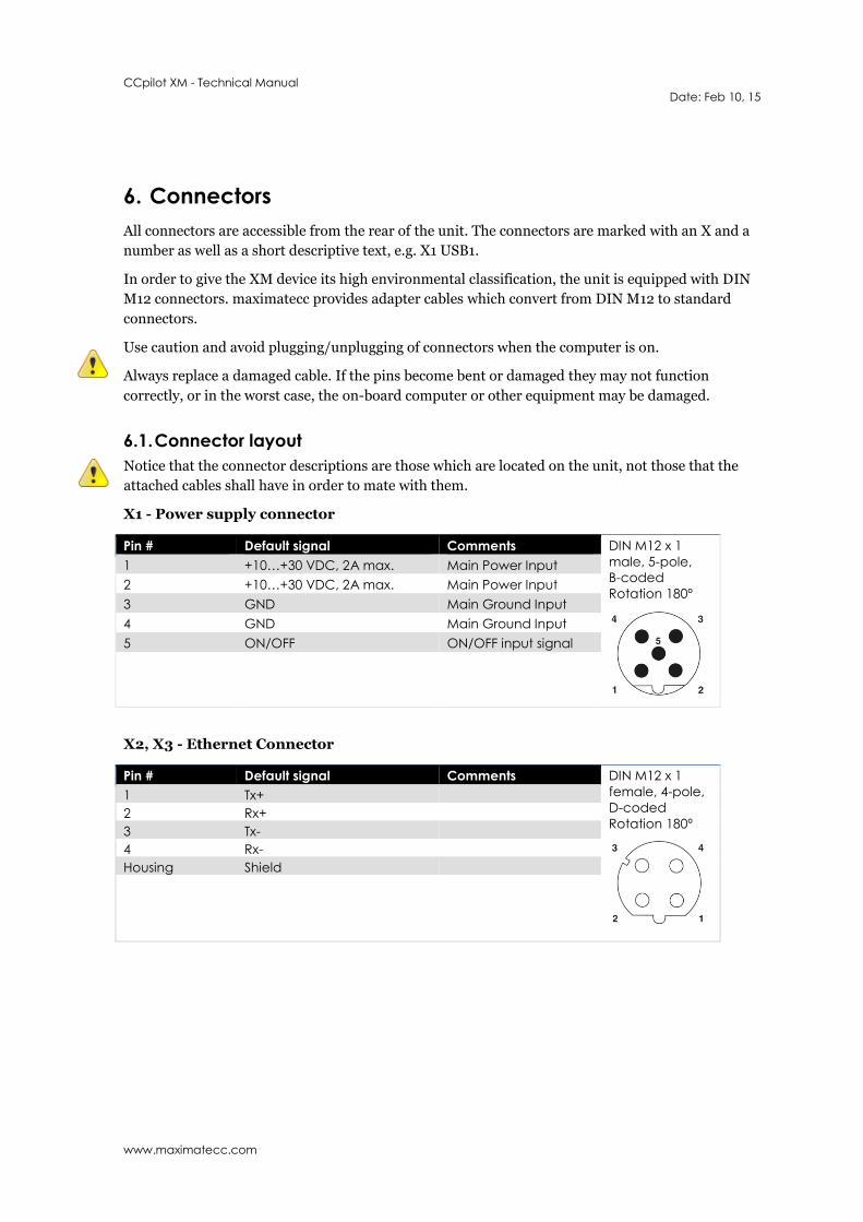
X1 - Power supply connector
Pin # Default signal Comments DIN M12 x 1
male, 5-pole,
B-coded
Rotation 180º
1 +10…+30 VDC, 2A max. Main Power Input
2 +10…+30 VDC, 2A max. Main Power Input
3 GND Main Ground Input
4 GND Main Ground Input
5 ON/OFF ON/OFF input signal
X2, X3 - Ethernet Connector
Pin # Default signal Comments DIN M12 x 1
female, 4-pole,
D-coded
Rotation 180º
1 Tx+
2 Rx+
3 Tx-
4 Rx-
Housing Shield
CCpilot XM - Technical Manual
Date: Feb 10, 15
www.maximatecc.com
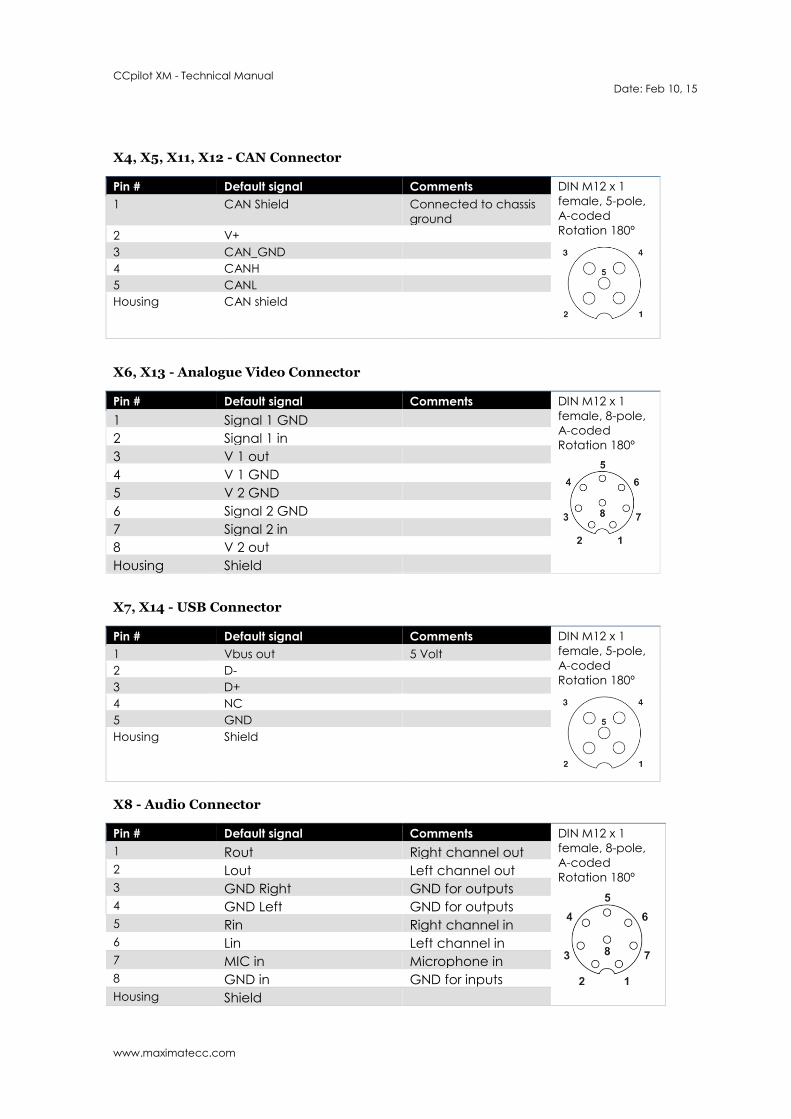
X4, X5, X11, X12 - CAN Connector
Pin # Default signal Comments DIN M12 x 1
female, 5-pole,
A-coded
Rotation 180º
1 CAN Shield Connected to chassis
ground
2 V+
3 CAN_GND
4 CANH
5 CANL
Housing
CAN shield
X6, X13 - Analogue Video Connector
Pin # Default signal Comments DIN M12 x 1
female, 8-pole,
A-coded
Rotation 180º
1 Signal 1 GND
2 Signal 1 in
3 V 1 out
4 V 1 GND
5 V 2 GND
6 Signal 2 GND
7 Signal 2 in
8 V 2 out
Housing Shield
X7, X14 - USB Connector
Pin # Default signal Comments DIN M12 x 1
female, 5-pole,
A-coded
Rotation 180º
1 Vbus out 5 Volt
2 D-
3 D+
4 NC
5 GND
Housing
Shield
X8 - Audio Connector
Pin # Default signal Comments DIN M12 x 1
female, 8-pole,
A-coded
Rotation 180º
1 Rout Right channel out
2 Lout Left channel out
3 GND Right GND for outputs
4 GND Left GND for outputs
5 Rin Right channel in
6 Lin Left channel in
7 MIC in Microphone in
8 GND in GND for inputs
Housing Shield

CCpilot XM - Technical Manual
Date: Feb 10, 15
www.maximatecc.com
X10 – I/O Connector
Pin # Default signal Comments DIN M12 x 1
female, 8-pole,
A-coded
Rotation 180º
1 DIG 1 Digital input
2 DIG 2 Digital input
3 DIG GND Digital GND
4 NC
5 DIG GND Digital GND
6 DIG GND Digital GND
7 DIG 3 Digital input
8 DIG 4 Digital input
Housing
X15 - Serial Port Connector
Pin # Default signal Comments DIN M12 x 1
male, 8-pole,
A-coded
Rotation 180º
1 NC
2 RxD
3 TxD
4 NC
5 GND
6 NC
7 RTS
8 CTS
Housing Shield
X16 - GPS Antenna Connector
Pin # Default signal Comments RP-TNC, female,
50ohm
1 Antenna signal Digital input
Housing
Antenna ground Digital input
X17 - GPRS Antenna Connector
Pin # Default signal Comments RP-TNC, female,
50ohm
1 Antenna signal
Housing Antenna ground
CCpilot XM - Technical Manual
Date: Feb 10, 15
www.maximatecc.com
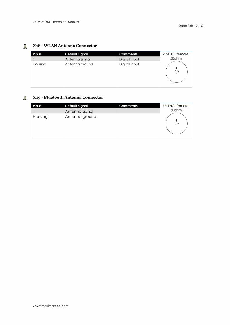
X18 - WLAN Antenna Connector
Pin # Default signal Comments RP-TNC, female,
50ohm
1 Antenna signal Digital input
Housing
Antenna ground Digital input
X19 - Bluetooth Antenna Connector
Pin # Default signal Comments RP-TNC, female,
50ohm
1 Antenna signal
Housing Antenna ground
CCpilot XM - Technical Manual
Date: Feb 10, 15
www.maximatecc.com
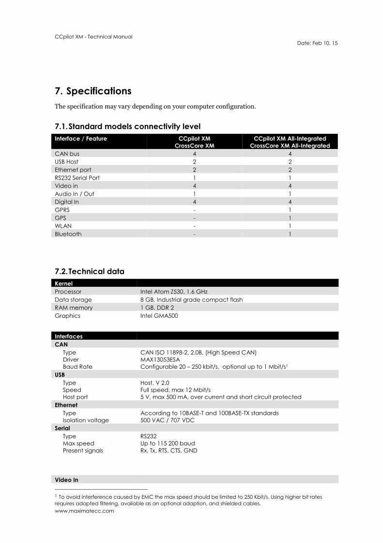
7. Specifications
The specification may vary depending on your computer configuration.
7.1. Standard models connectivity level
Interface / Feature CCpilot XM
CrossCore XM
CCpilot XM All-Integrated
CrossCore XM All-Integrated
CAN bus 4 4
USB Host 2 2
Ethernet port 2 2
RS232 Serial Port 1 1
Video in 4 4
Audio In / Out 1 1
Digital In 4 4
GPRS - 1
GPS - 1
WLAN - 1
Bluetooth - 1
7.2. Technical data
Kernel
Processor Intel Atom Z530, 1.6 GHz
Data storage 8 GB, Industrial grade compact flash
RAM memory 1 GB, DDR 2
Graphics Intel GMA500
Interfaces
CAN
Type
Driver
Baud Rate
CAN ISO 11898-2, 2.0B, (High Speed CAN)
MAX13053ESA
Configurable 20 – 250 kbit/s, optional up to 1 Mbit/s1
USB
Type
Speed
Host port
Host, V 2.0
Full speed, max 12 Mbit/s
5 V, max 500 mA, over current and short circuit protected
Ethernet
Type
Isolation voltage
According to 10BASE-T and 100BASE-TX standards
500 VAC / 707 VDC
Serial
Type
Max speed
Present signals
RS232
Up to 115 200 baud
Rx, Tx, RTS, CTS, GND
Video In
1 To avoid interference caused by EMC the max speed should be limited to 250 Kbit/s. Using higher bit rates
requires adapted filtering, available as an optional adaption, and shielded cables.
CCpilot XM - Technical Manual
Date: Feb 10, 15
www.maximatecc.com
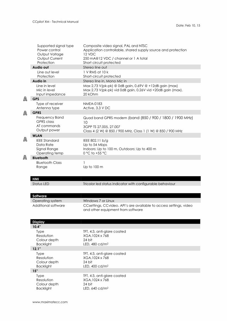
Supported signal type
Power control
Output Voltage
Output Current
Protection
Composite video signal, PAL and NTSC
Application controllable, shared supply source and protection
12 VDC
250 mA@12 VDC / channel or 1 A total
Short circuit protected
Audio out Stereo line out
Line out level
Protection
1 V RMS at 10 k
Short-circuit protected
Audio in Stereo line in, Mono Mic in
Line in level
Mic in level
Input impedance
Max 2.73 V(pk-pk) @ 0dB gain, 0.69V @ +12dB gain (max)
Max 2.73 V(pk-pk) vid 0dB gain, 0.26V vid +20dB gain (max).
20 kOhm
GPS
Type of receiver
Antenna type
NMEA-0183
Active, 3.3 V DC
GPRS
Frequency Band
GPRS class
AT commands
Output power
Quad band GPRS modem (band (850 / 900 / 1800 / 1900 MHz)
10 3GPP TS 27.005, 27.007
Class 4 (2 W) @ 850 / 900 MHz, Class 1 (1 W) @ 850 / 900 MHz
WLAN
IEEE Standard
Data Rate
Signal Range
Operating temp
IEEE 802.11 b/g
Up to 54 Mbps
Indoors: Up to 100 m, Outdoors: Up to 400 m
0 °C to +55 °C
Bluetooth
Bluetooth Class
Range
1
Up to 100 m
HMI
Status LED Tricolor led status indicator with configurable behaviour
Software
Operating system Windows 7 or Linux
Additional software CCsettings, CCvideo. API’s are available to access settings, video
and other equipment from software
Display
10.4”
Type
Resolution
Colour depth
Backlight
TFT, 4:3, anti-glare coated
XGA,1024 x 768
24 bit
LED, 480 cd/m2
12.1”
Type
Resolution
Colour depth
Backlight
TFT, 4:3, anti-glare coated
XGA,1024 x 768
24 bit
LED, 400 cd/m2
15”
Type
Resolution
Colour depth
Backlight
TFT, 4:3, anti-glare coated
XGA,1024 x 768
24 bit
LED, 640 cd/m2
CCpilot XM - Technical Manual
Date: Feb 10, 15
www.maximatecc.com
Power Supply
Supply Voltage 12 or 24 V nominal
Power Consumption < 2 A at 24 V
7.3. Environmental tolerance
Environmental Test Standard
Dry Heat IEC 60068-2-2 Operating: +70°C, 24h Storage: +85°C, 24h
Damp Heat IEC 60068-2-30 Operation: +25°C / +55°C >93% RH 6*24h
Cold IEC 60068-2-1 Operating: -25°C, 24h Storage: -40°C, 24h
Change of temperature IEC 60068-2-14 -25°C to +30°C, 5C/min 3hr hold time, 20 cycles
Vibration IEC 60068-2-64 0,01 g2/Hz 10-200 Hz 3x0.5h
Shock IEC 60068-2-29 5 g / 11ms 3x ±1000 bumps
EMC Electrical Transient ISO 7637-2 Pulse 1: -50V 2: +25V
3a: -35V
3b: +35V
4: -5V
5: +70V
EMC Immunity, ESD EN 61000-4-2 8 kV air, 6 kV contact
EMC Immunity, RF ISO 11452-2
ISO 11452-4
RF electromagnetic field 200-1000MHz 30V/m
Bulk Current Injection
20-200MHz 60mA
EMC Emission ISO 14982 Radiated Nar.b. Bro.b. MHz dBµV/m dBµV/m
30-75 54-44 64-54
75-400 44-55 54-65
400-1000 55 65
EMC Radiated RF immunity EN 61000-4-3 RF electromagnetic field 80M-1GHz 10V/m
1G-2GHz 3V/m
2G-2,7GHz 1V/m
EMC Burst EN 61000-4-4 ±2kV DC , ±1kV signal
EMC Surge EN 61000-4-5 ±0.5kV DC, ±1kV signal
EMC Induced RF 1) EN 61000-4-6 0.15-80MHz 10V
EMC Radiated RF emission EN 55011 MHz dBµV/m 30-230MHz 40
230-1000MHz 47
Enclosure EN 60529 IP65 1) Requires shielded cables for Serial, Ethernet, USB and Video.
The tests are performed with 24 V power level. The environmental tolerance may be affected by
external factors like mounting and shielded cables etc.
7.3.1. FCC Notice to Users
Users are not permitted to make changes or modify the device in any way. Changes or
modifications not expressly approved by the party responsible for compliance could void the user’s
authority to operate the equipment.
CCpilot XM - Technical Manual
Date: Feb 10, 15
www.maximatecc.com
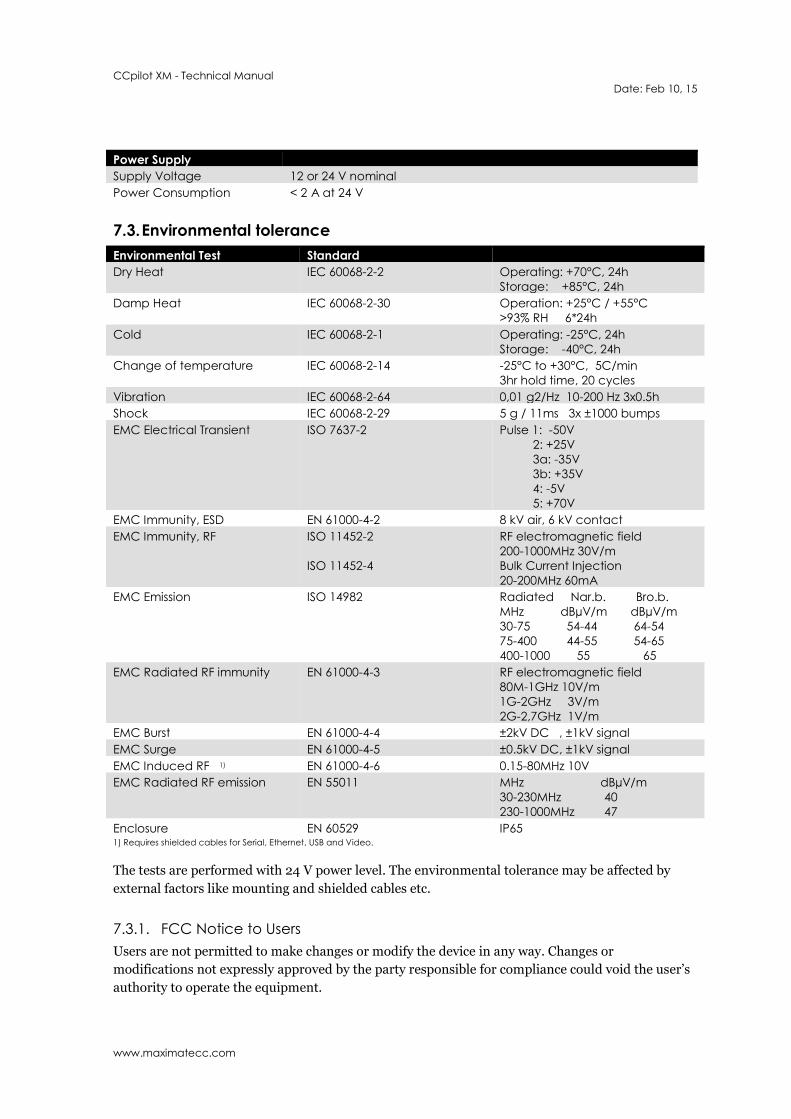
7.4. Weight and dimensions
7.4.1. CCpilot XM 10.4”
Description
Enclosure size 278 x 215 x 71 mm (W x H x D)
Weight 2,86 Kg
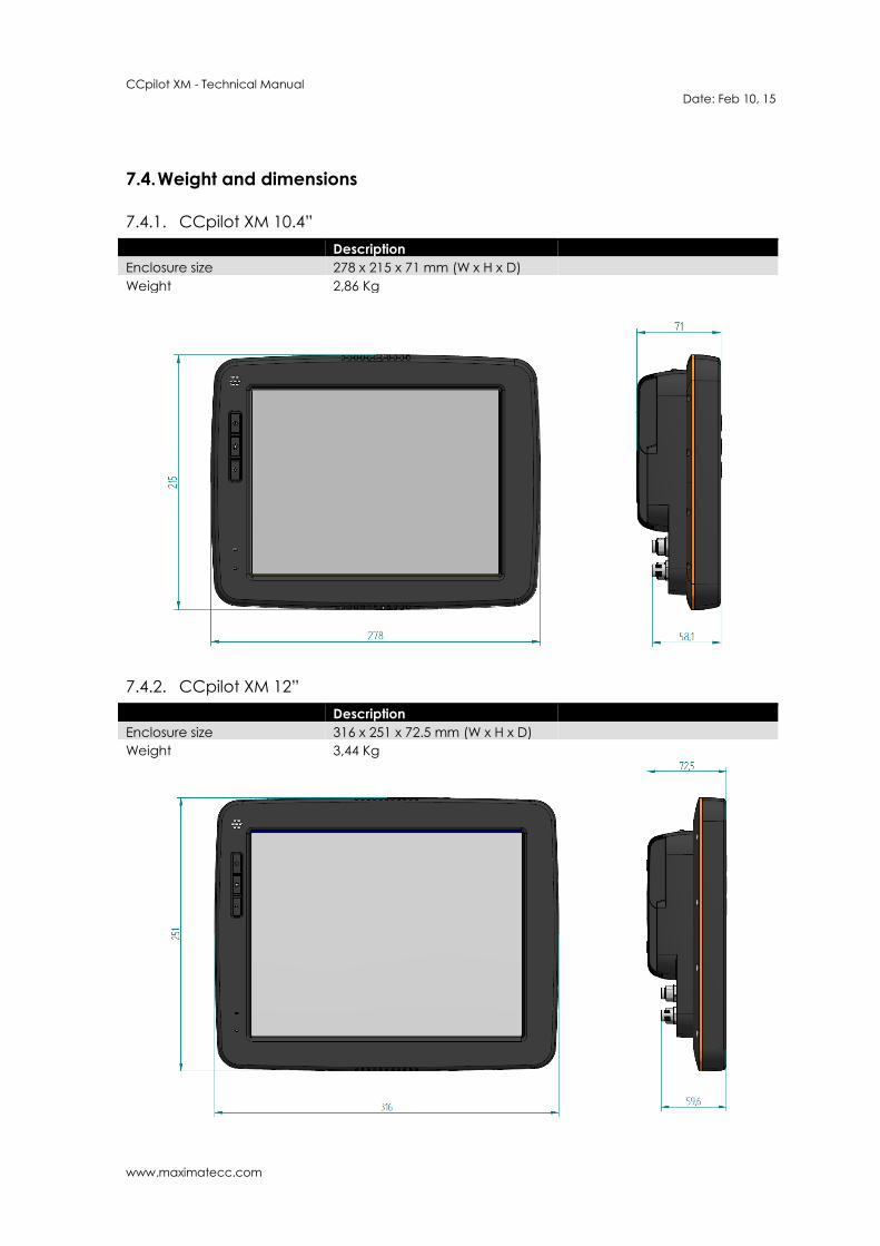
7.4.2. CCpilot XM 12”
Description
Enclosure size 316 x 251 x 72.5 mm (W x H x D)
Weight 3,44 Kg
CCpilot XM - Technical Manual
Date: Feb 10, 15
www.maximatecc.com
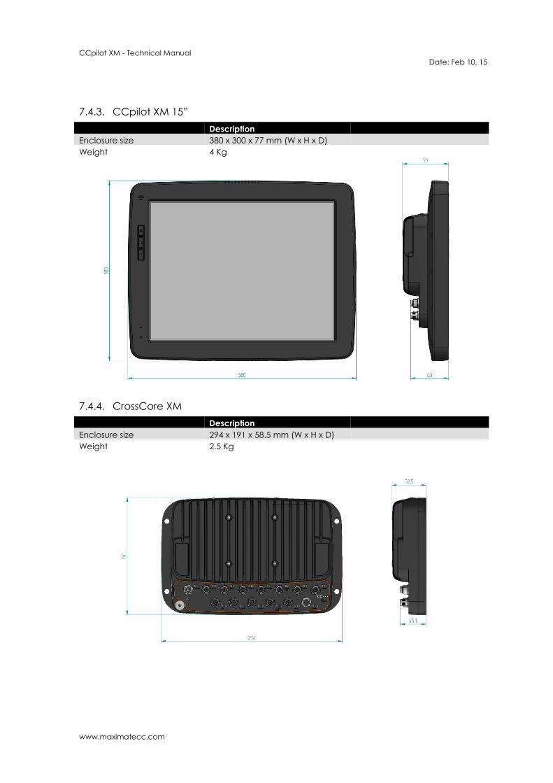
7.4.3. CCpilot XM 15”
Description
Enclosure size 380 x 300 x 77 mm (W x H x D)
Weight 4 Kg
7.4.4. CrossCore XM
Description
Enclosure size 294 x 191 x 58.5 mm (W x H x D)
Weight 2.5 Kg
CCpilot XM - Technical Manual
Date: Feb 10, 15
www.maximatecc.com
8. Technical Support
Contact your reseller or supplier for help with possible problems with your XM device. In order to
get the best help, you should have your XM device in front of you and be prepared with the
following information before you contact support.
Part number and serial number of the unit, which you find on the brand label
Date of purchase, which is found on the invoice
The conditions and circumstances under which the problem arises
LED indicator flash patterns.
Possible error messages which are shown.
Operating system type and its version number.
The XM Device log files (if possible)
Prepare a system report on the XM device, from within CCsettings (if possible).
Information regarding possible external equipment which is connected to the XM device.

CCpilot XM - Technical Manual
Date: Feb 10, 15
www.maximatecc.com
9. Trade Mark, etc.
© 2014 maximatecc
All trademarks sighted in this document are the property of their respective owners.
CCpilot is a trademark which is the property of maximatecc.
Intel is a registered trademark which is the property of Intel Corporation in the USA and/or other
countries. Linux is a registered trademark of Linus Torvalds. Microsoft and Windows are registered
trademarks which belong to Microsoft Corporation in the USA and/or other countries.
maximatecc AB is not responsible for editing errors, technical errors or for material which has been
omitted in this document. maximatecc is not responsible for unintentional damage or for damage
which occurs as a result of supplying, handling or using of this material including the devices and
software referred to herein. The information in this handbook is supplied without any guarantees
and can change without prior notification.
maximatecc respects the intellectual property of others, and we ask our users to do the same.
Where software based on maximatecc software or products is distributed, the software may only be
distributed in accordance with the terms and conditions provided by the reproduced licensors.
For end-user license agreements (EULAs), copyright notices, conditions, and disclaimers,
regarding certain third-party components used in the XM device, refer to the copyright notices
documentation.
CCpilot XM - Technical Manual
Date: Feb 10, 15
www.maximatecc.com
10. Index
A
Adapter cables................................................... 16
Audio .................................................................... 13
Audio Connector ............................................... 17
B
Back side ................................................................ 7
Basic operations ................................................. 11
Battery ....................................................... 8, 11, 12
Bluetooth .............................................................. 15
Bluetooth Antenna Connector ........................ 19
Brightness ............................................................. 12
Buzzer .................................................................... 13
C
Cable installation................................................ 10
Calibration of touchscreen .............................. 12
CAN ...................................................................... 14
CAN Connector .................................................. 17
Care ........................................................................ 5
Cleaning ................................................................ 6
Compact Flash ................................................... 13
Connectors .......................................................... 16
Contact support ................................................. 25
D
Digital inputs ........................................................ 14
Dimensions ........................................................... 23
Display .................................................................... 7
Double click......................................................... 12
E
Enclosure size 10.4 .............................................. 23
Enclosure size 12 .......................................... 23, 24
Environmental test .............................................. 22
Environmental tolerance .................................. 22
Environmental Tolerance .................................... 6
Ethernet ................................................................ 14
Ethernet Connector ........................................... 16
External interface description .......................... 16
F
Fan Connector .................................................... 18
Forced shut down .............................................. 12
Front ........................................................................ 7
Fuse .................................................................. 8, 11
G
GoreTex ................................................................10
GPRS Antenna Connector ................................18
GPRS/GSM ...........................................................15
GPS ........................................................................14
GPS Antenna Connector ..................................18
H
Hook up of Power supply ............................. 8, 11
I
I/O Connector.....................................................18
Indicators .............................................................12
Inputs ....................................................................16
Installation .............................................................. 8
Installing cables ..................................................10
Introduction ........................................................... 4
L
LED .........................................................................12
Light sensor ..........................................................13
M
Maintenance ........................................................ 6
Memory ................................................................13
N
NTSC ......................................................................13
O
ON/OFF ............................................................ 8, 11
Outputs .................................................................16
Overview ................................................................ 7
P
PAL ........................................................................13
Pins ........................................................................16
Ports .......................................................................16
Power supply connector ...................................16
Power supply installation .............................. 8, 11
Preheating ...........................................................11
Push-buttons ........................................................12
CCpilot XM - Technical Manual
Date: Feb 10, 15
www.maximatecc.com
R
Rain/Moisture ...................................................... 10
Rear ......................................................................... 7
Right click ............................................................. 12
RS232 ..................................................................... 14
S
Serial ...................................................................... 14
Serial Port Connector .................................. 17, 18
Shutting down ..................................................... 11
SIM card ................................................................. 8
Specification ....................................................... 20
Standard models ................................................ 20
Starting Up ........................................................... 11
Storage ................................................................. 13
Support ................................................................. 25
Suspend ................................................................ 12
T
Technical data.................................................... 20
Technical Support ..............................................25
Test standards ....................................................... 6
Thread depth ........................................................ 9
Torque ................................................................ 8, 9
Touch screen .......................................................12
Trade Mark ...........................................................26
Turning off ............................................................11
Turning on ............................................................11
U
USB .........................................................................14
USB Connector ....................................................17
V,W
Warming ...............................................................11
Vehicle´s fuse ................................................. 8, 11
Weight ..................................................................23
Video ....................................................................13
WLAN ....................................................................15
WLAN Antenna Connector .............................19