Embed Size (px)
Citation preview
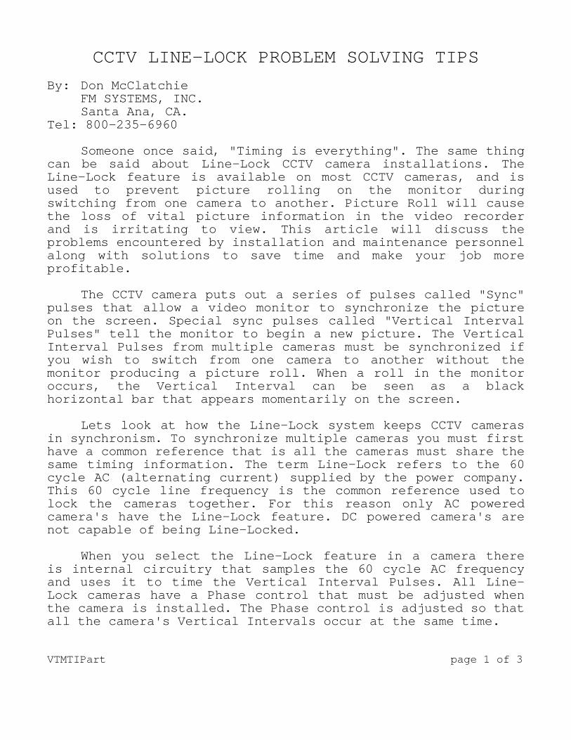
CCTV LINE-LOCK PROBLEM SOLVING TIPS By: Don McClatchie FM SYSTEMS, INC. Santa Ana, CA. Tel: 800-235-6960 Someone once said, "Timing is everything". The same thing can be said about Line-Lock CCTV camera installations. The Line-Lock feature is available on most CCTV cameras, and is used to prevent picture rolling on the monitor during switching from one camera to another. Picture Roll will cause the loss of vital picture information in the video recorder and is irritating to view. This article will discuss the problems encountered by installation and maintenance personnel along with solutions to save time and make your job more profitable. The CCTV camera puts out a series of pulses called "Sync" pulses that allow a video monitor to synchronize the picture on the screen. Special sync pulses called "Vertical Interval Pulses" tell the monitor to begin a new picture. The Vertical Interval Pulses from multiple cameras must be synchronized if you wish to switch from one camera to another without the monitor producing a picture roll. When a roll in the monitor occurs, the Vertical Interval can be seen as a black horizontal bar that appears momentarily on the screen. Lets look at how the Line-Lock system keeps CCTV cameras in synchronism. To synchronize multiple cameras you must first have a common reference that is all the cameras must share the same timing information. The term Line-Lock refers to the 60 cycle AC (alternating current) supplied by the power company. This 60 cycle line frequency is the common reference used to lock the cameras together. For this reason only AC powered camera's have the Line-Lock feature. DC powered camera's are not capable of being Line-Locked. When you select the Line-Lock feature in a camera there is internal circuitry that samples the 60 cycle AC frequency and uses it to time the Vertical Interval Pulses. All Line-Lock cameras have a Phase control that must be adjusted when the camera is installed. The Phase control is adjusted so that all the camera's Vertical Intervals occur at the same time. VTMTIPart page 1 of 3
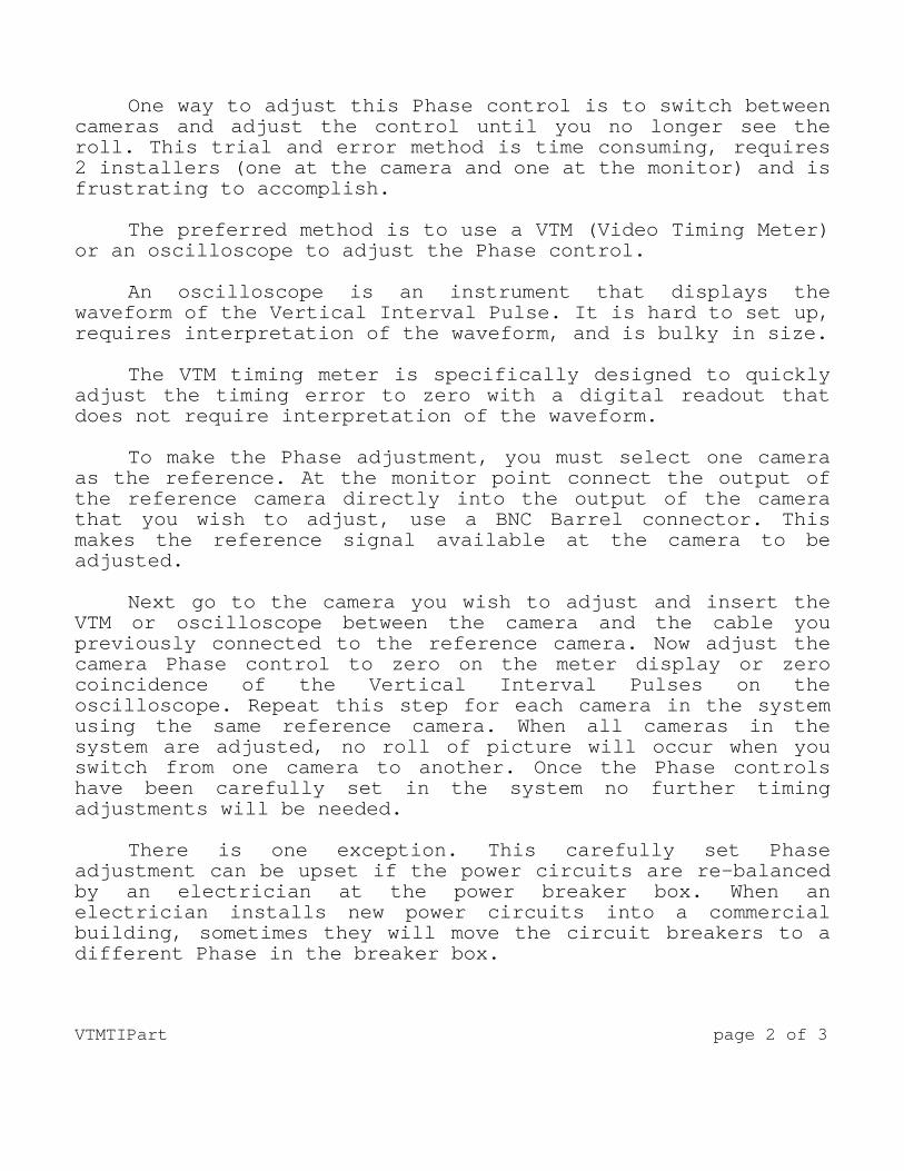
One way to adjust this Phase control is to switch between cameras and adjust the control until you no longer see the roll. This trial and error method is time consuming, requires 2 installers (one at the camera and one at the monitor) and is frustrating to accomplish. The preferred method is to use a VTM (Video Timing Meter) or an oscilloscope to adjust the Phase control. An oscilloscope is an instrument that displays the waveform of the Vertical Interval Pulse. It is hard to set up, requires interpretation of the waveform, and is bulky in size. The VTM timing meter is specifically designed to quickly adjust the timing error to zero with a digital readout that does not require interpretation of the waveform. To make the Phase adjustment, you must select one camera as the reference. At the monitor point connect the output of the reference camera directly into the output of the camera that you wish to adjust, use a BNC Barrel connector. This makes the reference signal available at the camera to be adjusted. Next go to the camera you wish to adjust and insert the VTM or oscilloscope between the camera and the cable you previously connected to the reference camera. Now adjust the camera Phase control to zero on the meter display or zero coincidence of the Vertical Interval Pulses on the oscilloscope. Repeat this step for each camera in the system using the same reference camera. When all cameras in the system are adjusted, no roll of picture will occur when you switch from one camera to another. Once the Phase controls have been carefully set in the system no further timing adjustments will be needed. There is one exception. This carefully set Phase adjustment can be upset if the power circuits are re-balanced by an electrician at the power breaker box. When an electrician installs new power circuits into a commercial building, sometimes they will move the circuit breakers to a different Phase in the breaker box. VTMTIPart page 2 of 3
In commercial buildings the utility power is Three Phase, that is three separate 60 cycle lines whose phase is 120 degrees apart. Moving the power line that your camera is on to a different phase will throw off the timing and require a re-adjustment of the phase control on the camera. If monitor personnel complain about picture roll, a fast check of timing can be made. Go to the monitor station and connect one camera as a reference to the VTM or oscilloscope and then connect each camera one at a time to make the measurement. The timing should be zero +/- 3 Video Lines or Sync Pulses. A roll can be noticed if the difference between cameras is more than a few lines. As the line difference between cameras increase so does the noticeable roll. If you measure a camera and the readings seem to change, that indicates the camera is not Line-Locked. The solution is to select the Line-Lock feature on the camera or replace it with one that has Line-Lock. A clear understanding of how the Line-Lock system works combined with a way of measuring the Phase of each camera will let you set them quickly and correctly with confidence.
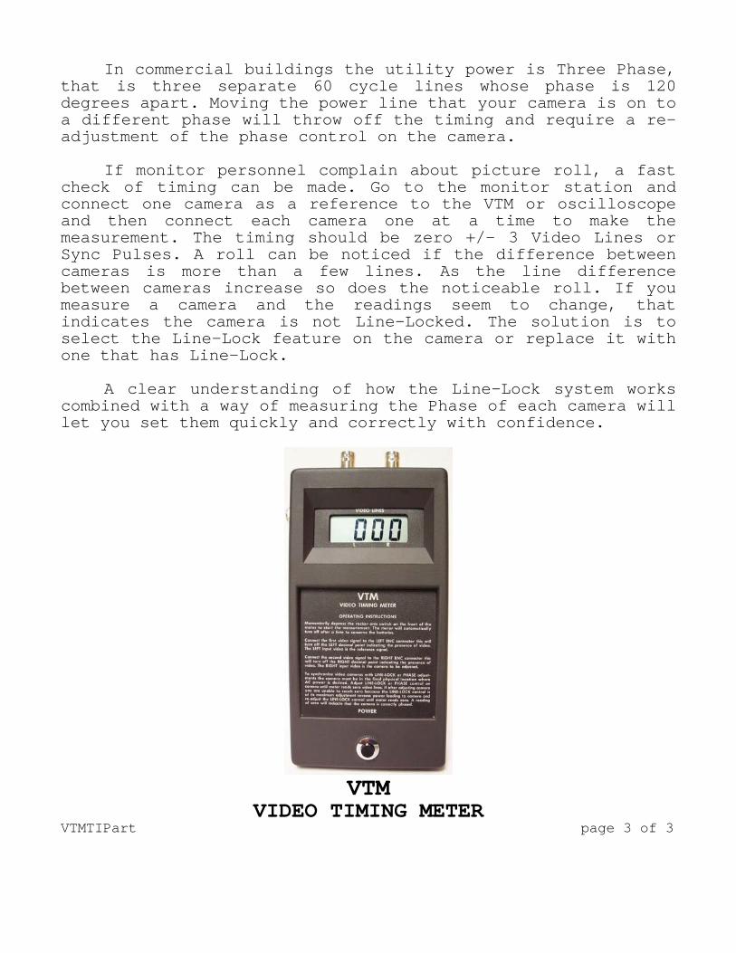
VTM
VIDEO TIMING METER VTMTIPart page 3 of 3