Embed Size (px)
Citation preview
1
MANUAL DESIGN AND ANALYSIS OF
MULTI-STORIED OFFICE BUILDING
A PROJECT REPORT
Submitted by
B.MAHENDER RAO NAYAK (09241A0120)
V.PRAVEEN REDDY (09241A0126)
K.RAJIV (09241A0130)
ABDUL SHABBEER (09241A0139)
VIVEK PATAK (10245A0112)
In fulfilment for the major project of B.TECH in Civil Engineering
GOKARAJU RANGARAJU INSTITUTION OF
ENGINEERING & TECHNOLOGY
HYDERABAD

2
DECLARATION
We here by declare that the project work entitled “MANUAL DESIGN AND
ANALYSIS OF MULTI-STORIED OFFICE BUILDING” is a record of an original
work done by us under the guidance of Mr.V. Mallikarjun Reddy, Associate Prof.,
Department of civil Engineering, GRIET. This project work is done in the fulfilment of the
requirements of the major project. This is a bonafide work carried out by us and the results
provided in this project report have not been copied from any source. The results provided in
this have not been submitted to any other University or Institute for the award of any degree
or diploma.
Date: 15-04-2013
Place: Hyderabad
Civil Engineering Department
GRIET, Hyderabad.

3
ACKNOWLEDGMENT
We express our in deep gratitude to our guide Mr. V.MALLIKARJUN REDDY,
Associate Professor, Department of Civil Engineering (GRIET), for his guidance and extreme
care taken by him in helping us to complete the project work successfully. We are grateful to
him for the extensive care rendered to us right from the initiation of the project to the final
editing of the manuscript. This project would not have been completed without his help who
has given enough exposure in the areas related to the work and as well as provided us with
his ever present help.
We express our sincere thanks to Dr. G.Venkata Ramana, Head of the Department
Civil Engineering, for his support and guidance for doing this project. We are also thankful
to all the teaching and non-teaching staff of Civil Engineering Department.
We are also thankful to each and everyone name by name who helped us directly or
indirectly in execution of this project.
4
GOKARAJU RANGARAJU
INSTITUTE OF ENGINEERING AND TECHNOLOGY , HYDERABAD
CERTIFICATECERTIFICATECERTIFICATECERTIFICATE
This is to certify that the dissertation entitled “MANUAL DESIGN AND
ANALYSIS OF MULTI-STORIED OFFICE BUILDING” is a project work done
under the Guidance of Mr. V. Mallikarjun Reddy (Assosiate professor, civil
engineering department, GRIET).
PROJECT BY TEAM OF
B.MAHENDER RAO NAYAK (09241A0120)
V.PRAVEEN REDDY (09241A0126)
K.RAJIV (09241A0130)
ABDUL SHABBEER (09241A0139)
VIVEK PATAK (10245A0112)
Prof. Dr. G. Venkata Ramana V. Mallikarjun Reddy
HOD, Civil Engineering Project Guide, Civil
Engineering
Signature of the External Examiner

5
ABSTRACT
Due to advancement of technology humans are creating software to make
things easier and time saving. As a result in the civil engineering point of view
the manual design of buildings has lost its importance. It is true that design
using a software is easy and time saving and mostly results are accurate.
On the other hand manual design is a cumbersome job and a time consuming
process, but for a beginner manual design helps to understand the basic
fundamentals that are involved in designing a building. Once a person gains
knowledge in manual design he will be knowing the elements involved in
designing and can easily understand the usage of software.
The main objective of the project is to use the knowledge that we have learnt
during our graduation and learn to deal with practical cases. We wish this
project will fulfill our purpose.
6
CONTENTS
PG.NO
CHAPTER-I
1.INTRODUCTION .......................................................................... 7
CHAPTER-II
2.DESIGN OF SLABS ...................................................................... 10
CHAPTER-III
3. Analysis of frames.............................................................. 45
CHAPTER-IV
4. DESIGN OF BEAMS...................................................................... 115
CHAPTER-V
5. DESIGN OF COLUMNS.................................................. 224
CHAPTER-VI
6. DESIGN OF FOOTINGS.................................................. 275
CHAPTER-VII
7. DESIGN OF STAIR CASE.............................................. 293
CHAPTER-VIII
8. CONCLUSION................................................................. 298
9. REFERENCE.................................................................... 299

7
1. INTRODUCTION
The population explosion and advent of industrial revolution led to the exodus of
people from villages to urban areas. This urbanisation led to a new problem – less space for
housing, work and more people. Because of the demand for land, the land costs got
skyrocketed. So, under the changed circumstances, the vertical growth of buildings i.e.
constructions of multi-storeyed buildings has become inevitable both for residential and as
well as office purposes.
For multi-storeyed buildings, the conventional load bearing structures become
uneconomical as they require larger sections to resist huge moments and loads. But in a
framed structure, the building frame consists of a network of beams and columns which are
built monolithically and rigidly with each other at their joints. Because of this rigidity at the
joints, there will be reduction in moments and also the structure tends to distribute the loads
more uniformly and eliminate the excessive effects of localised loads. Therefore in non-load
bearing framed structures, the moments and forces become less which in turn reduces the
sections of the members. As the walls don’t take any load, they are also of thinner
dimensions. So, the lighter structural components and walls reduce the self weight of the
whole structure which necessitates a cheaper foundation. Also, the lighter walls which can be
easily shifted provide flexibility in space utilisation. In addition to the above mentioned
advantages the framed structure is more effective in resisting wind loads and earth quake
loads.
Work done in this project:
A plot of 369.75 m2 has been selected for the construction of a multi-storeyed office
building. In the office building the functions will be different and it plays a major role
because of different loads acts on different slabs. The frame analysis requires the dimensions
of the members. For the analysis, 6 substitute frames taken in transverse direction and in
longitudinal direction the net moment acting is zero, and this is due to symmetrycity . For the
maximum mid span moment obtained from the analysis, a T-beam has been designed and for
the support moment ‘doubly reinforced’ section has been provided. Stair case has also been
designed. Isolated rectangular sloped footings have been designed to transfer the load to the
ground strata.
8
Analysis of structure:
Kani’s method and substitute frame method is generally used to analyse a multi-
storeyed frame. The substitute frame method requires less computations and easier to carry
out the analysis. Therefore, here substitute frame method has been employed to carry out the
frame analysis and method is discussed in the following paragraphs.
Theoretically, a load applied at any point of the structure cause reactions at all
sections of the frame, but a close study of this aspect has shown that the moments in any
beam or column are mainly due to the loads on spans very close to it. The effect of loads on
distant panels is small. To facilitate the determination of moments in any member of a frame,
it is usual to analyse only a small portion of the frame consisting of adjacent members only.
Such a small portions are termed ‘SUBSTITUTE FRAMES’.
The reactions worked out with the help of substitute frame may sometimes appear to
be lower by about 10% compared with the value obtained from exact analysis. But it may be
mentioned that for analysis all the panels are located at the same time. Such a combination of
loading is highly improbable in practice. Thus the results given by substitute frames are safe
for all practical purposes.
Design concept:
There are three design philosophies to design a reinforced concrete structures. They
are:
1. Working stress method,
2. Ultimate load method and
3. Limit state method.
In the ‘working stress’ method it is seen that the permissible stresses for concrete and
steel are not exceeded anywhere in the structure when it is subjected to the worst
combination of working loads. A linear variation of stress form zero at the neutral axis to
the maximum stress at the extreme fibre is assumed.
Practically, the stress strain curve for concrete is not linear as it was assumed in
working stress method. So, in ‘ultimate load’ design an idealised form of actual stress
strain diagram is used and the working loads are increased by multiplying them with the
load factors.

9
The basis for ‘limit state’ method is a structure with appropriate degrees of reliability
should be able to withstand safely all loads that are liable to act on it throughout its life
and it should also satisfy the serviceability requirements such as limitations on deflection
and cracking.
Limit state method is the most rational method of the three methods. It considers the
actual behaviour of the materials at failure and also it takes serviceability also into
consideration. Therefore, limit state method has been employed in this work.

10
2.DESIGN OF SLABS
Typically we divided the slabs into two types:
i. Roof Slab and
ii. Floor Slab
In case of roof slab the live load obtained is less compared to the floor slab. Therefore we
first design the roof slab and then floor slabs.
We have two types of supports. They are:
1. Ultimate support and
2. Penultimate support
Ultimate support is the end support and the penultimate supports are the intermediate
supports.
Ultimate support tends to have a bending moment of Wu x L
2
10 and the penultimate supports
have Wu x L
2
12
Design of roof slab:
It is a continuous slab on the top of the building which is also known as terrace.
Generally terrace has less live load and it is empty in most of the time except some occasions
in case of any residential building. In case of office buildings it will be empty and live load
act is very less.
According to the end conditions and the dimensions, the slabs are divided into 4 types. They
are Roof S1, Roof S2, Roof S3 and Roof S4.
Slab Dimensions (M x M)
Roof S1 8.62 X 3.05
Roof S2 8.62 X 3.05
Roof S3 5.78 X 3.05
Roof S4 5.78 X 3.05

11
We can observe the slab panels in the above figure and all the slabs are designed as one way
slab for the easy arrangement of the reinforcement and ease of work.
Roof S1 and Roof S2 are the slabs with same dimensions but with different end conditions.
Roof S3 and Roof S4 are also the slabs with the same conditions as mentioned above.
But the point to be noted is that all the Slabs have same shorter span and in the design of one
way slab shorter span is of more importance. Therefore we design any two slabs with
different end conditions and the remaining two slabs also follow the same design.
Design of Roof Slab S1:
Calculation of Depth (D) by using modification factor:
Assume the percentage of the tension reinforcement (Pt) provided is 0.4%
From IS456-2000, P38 Fig4, we get the modification factor (α) = 1.4
Required Depth (D) = L
ra + d
1

12
Where, L
ra =
Span
allowable L
d ratio
d1 = Centre of the reinforcement to the end fibre (= 20mm for slab)
From IS456-2000, P39, Clause 24 & Clause 23.2 for continuous span we have
Span
Effective depth =
L
d = 26
ra = 26 x 1.4 = 36.4
Therefore, D = 3.05 x 10
3
36.4 + 20 = 103.79mm say 110 mm
Effective depth (d) = D – d1 = 110 – 20 = 90mm
Loads:
Dead loads (From IS875 – Part 1):
Terrace water proofing = 2.5 KN/m2
Self weight of the slab = 1 x 1 x D x 25 = 110
1000 x 25
= 2.75 KN/m2
Live loads (From IS875 – Part 2):
Roof = 1.5 KN/m2
Total load (W) = 2.5 +2.75 + 1.5 = 6.75 KN/m2
Ultimate load or limit state load or design load (Wu) = 1.5 x W = 1.5 x 6.75
=10.125 KN/m2
Design moment: (for end panel)
Mu = Wu x L
2
10 =
10.125 x (3.05)2
10 = 9.42 KN-m

13
Calculation of area of steel:
From IS456-2000, P96, Clause G-1.1 (b) we have
Mu = 0.87 x fy x Ast x d x (1 - fy x Ast
fck x b x d )
Or
Ast = 0.5 x fck
fy (1-(1-4.6
Mu
fck x b x d )
1/2) b x d
9.42 x 106 = 0.87 x 415 x Ast x 90 x (1 -
415 x Ast
20 x 1000 x 90 )
Ast = 312.4 mm2
Spacing of 8mm φ bars = ast x 1000
Ast = π4
x 82 x
1000
312.4 = 160.9mm
Therefore, Provide 8mm φ @ 150mm c/c.
Distribution steel:
Ast = 0.12% of Ag
= 0.12
1000 x 110 x 1000 = 132 mm
2.
Spacing of 8mm φ bars = π4 x 8
2 x
1000
132 =380mm
Therefore, Provide 8mm φ @ 300mm c/c.

14
Design of Roof slab S2:
Depth D = 110mm
Total load (W) = 6.75 KN/m2
Limit state load (Wu) = 1.5 x 6.75 = 10.125 KN/m2
Design moment: (for intermediate panel)
Mu = Wu x L
2
12 =
10.125 x (3.05)2
12 = 7.85 KN-m
Calculation of area of steel:
Mu = 0.87 x fy x Ast x d x (1 - fy x Ast
fck x b x d )
7.85 x 106 = 0.87 x 415 x Ast x 90 x (1 -
415 x Ast
20 x 1000 x 90 )
Ast = 256.78 mm2
Spacing of 8mm φ bars = π4 x 8
2 x
1000
256.78 = 195.75mm
Therefore, Provide 8mm φ @ 190mm c/c.
Distribution steel:
Ast = 0.12% of Ag
= 0.12
1000 x 110 x 1000 = 132 mm2.
Spacing of 8mm φ bars = π4 x 8
2 x
1000
132 =380mm
Therefore, Provide 8mm φ @ 300mm c/c.

15
Design of Roof Slab S3 is same as Roof Slab S1.
Design of Roof Slab S4 is same as Roof Slab S2.
Area of steel at support next to end support:
From IS 456-2000, moment = Wu x L
2
10
Total Load acting on the support (Wu) = 10.125 KN/m
Therefore, Moment = 10.125 x (3.05)
2
10 = 9.42 KN-m
Calculation of Ast:
Mu = 0.87 x fy x Ast x d x (1 - fy x Ast
fck x b x d )
9.42 x 106 = 0.87 x 415 x Ast x 90 x (1 - 415 x Ast
20 x 1000 x 90 )
Ast = 312.4 mm2
Area of steel available by bending up the alternate bars of mid span steel:
From Slab S1 = 1
2 x 312.4 = 160.7 mm2
From Slab S2 = 1
2 x 256.78 = 128.39 mm
2
Total Ast (available) = 160.7 + 128.39 = 284.59 mm2
Therefore, extra bars required for Ast = 312.4 – 284.59 = 27.81 mm2
16
Area of steel at any other interior support:
From IS 456-2000, moment = Wu x L
2
12
Total Load acting on the support (Wu) = 10.125 KN/m
Therefore, Moment = 10.125 x (3.05)
2
12 = 7.85 KN-m
Calculation of Ast:
Mu = 0.87 x fy x Ast x d x (1 - fy x Ast
fck x b x d )
7.85 x 106 = 0.87 x 415 x Ast x 90 x (1 - 415 x Ast
20 x 1000 x 90 )
Ast = 256.78 mm2
Area of steel available by bending up the alternate bars of mid span steel:
From Slab S2 = 1
2 x 256.78 = 128.39 mm2
From Slab S2 = 1
2 x 256.78 = 128.39 mm2
Total Ast (available) = 128.39 + 128.39 = 284.59 mm2
Therefore Ast (available) = Ast (required)
No need of providing extra bars.

17
Design of Floor Slab:
It is the slab in which live load is more when compared to the roof slab. In this project
the slab is divided into 9 types according to the end condition and function of slab.
S1 - Toilet and WC’s
S2 - Office
S3 - Office sup dept.
S4 - Assembly hall
S5 (a), S5 (b) - Office chamber and waiting chamber
S6 (a), S6 (b) - Office
S7 - Library
S8 - Secretary Room
S9 (a), S9 (b) - Officers chamber

18
Floor Slab Dimensions
S1 to S5 (b) 8.62 x 3.05
S6 (a) to S9 (b) 5.78 x 3.05
DESIGN OF FLOOR SLAB (S1):
Calculation of Depth (D) by using modification factor:
Assume the percentage of the tension reinforcement (Pt) provided is 0.4%
From IS456-2000, P38 Fig4, we get the modification factor (α) = 1.4
Required Depth (D) = L
ra + d
1
Where, L
ra =
Span
allowable L
d ratio
d1 = Centre of the reinforcement to the end fibre (= 20mm for slab)
From IS456-2000, P39, Clause 24 & Clause 23.2 for continuous span we have
Span
Effective depth =
L
d = 26
ra = 26 x 1.4 = 36.4
Therefore, D = 3.05 x 10
3
36.4 + 20 = 103.79mm say 120 mm
Effective depth (d) = D – d1 = 120 – 20 = 100mm
Loads:
Dead loads (From IS875 – Part 1):
Floor finish = 1 KN/m2
Sanitary Blocks including filling = 2.5 KN/m2

19
Self weight of the slab = 1 x 1 x D x 25 = 120
1000 x 25
= 3 KN/m2
Live loads (From IS875 – Part 2):
Sanitary blocks public = 3 KN/m2
Corridor = 5 KN/m2
Maximum = 5 KN/m2
For Partition Wall = 1.5 KN/m2
Total load (W) = 1 + 2.5 +3 + 5 + 1.5 = 13 KN/m2
Ultimate load or limit state load or design load (Wu) = 1.5 x W = 1.5 x 13
=19.5 KN/m2
Design moment: (for end panel)
Mu = Wu x L2
10 =
19.5 x (3.05)2
10 = 18.14 KN-m
Calculation of area of steel:
From IS456-2000, P96, Clause G-1.1 (b) we have
Mu = 0.87 x fy x Ast x d x (1 - fy x Ast
fck x b x d )
Or
Ast = 0.5 x fck
fy (1-(1-4.6
Mu
fck x b x d )1/2) b x d
18.14 x 106 = 0.87 x 415 x Ast x 100 x (1 -
415 x Ast
20 x 1000 x 100 )
Ast = 569.79 mm2
Spacing of 10mm φ bars = ast x 1000
Ast = π4 x 10
2 x
1000
569.79 = 137.83mm
20
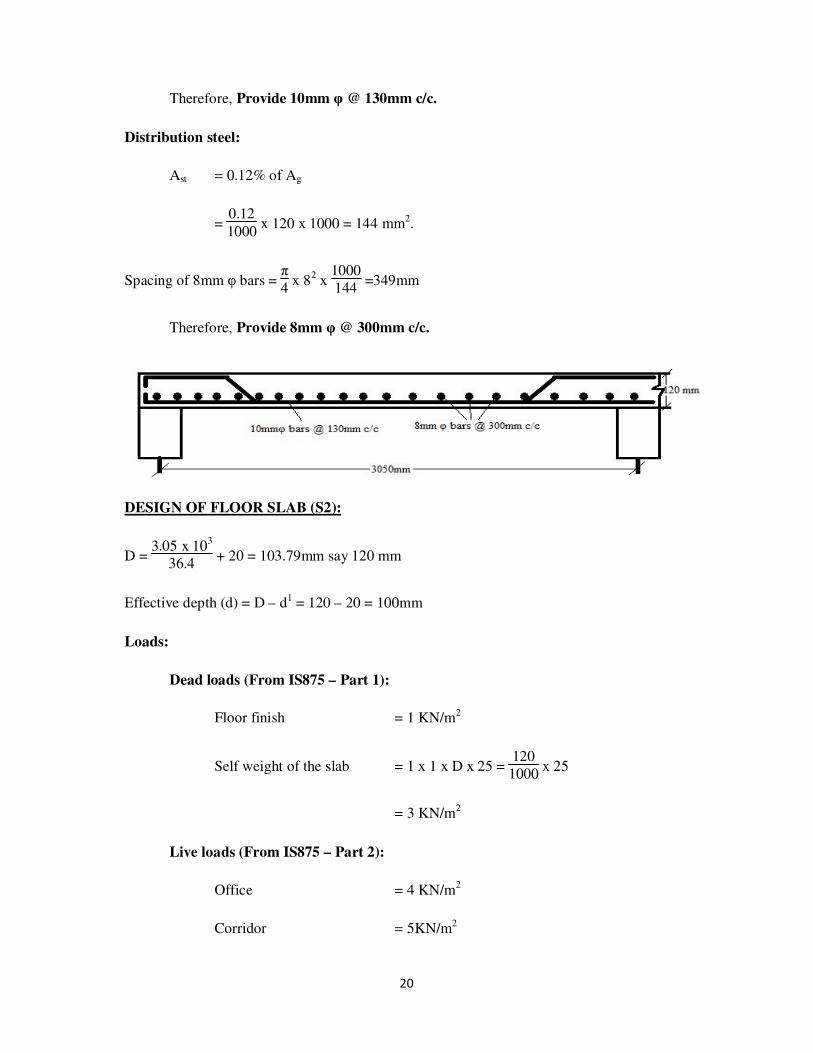
Therefore, Provide 10mm φ @ 130mm c/c.
Distribution steel:
Ast = 0.12% of Ag
= 0.12
1000 x 120 x 1000 = 144 mm2.
Spacing of 8mm φ bars = π4 x 8
2 x
1000
144 =349mm
Therefore, Provide 8mm φ @ 300mm c/c.
DESIGN OF FLOOR SLAB (S2):
D = 3.05 x 10
3
36.4 + 20 = 103.79mm say 120 mm
Effective depth (d) = D – d1 = 120 – 20 = 100mm
Loads:
Dead loads (From IS875 – Part 1):
Floor finish = 1 KN/m2
Self weight of the slab = 1 x 1 x D x 25 = 120
1000 x 25
= 3 KN/m2
Live loads (From IS875 – Part 2):
Office = 4 KN/m2
Corridor = 5KN/m2

21
Therefore, Maximum load = 5 KN/m2
For Partition wall = 1.5 KN/m2
Total load (W) = 5 +3 + 1 + 1.5 = 10.5 KN/m2
Ultimate load or limit state load or design load (Wu) = 1.5 x W = 1.5 x 10.5
=15.75 KN/m2
Design moment:
Mu = Wu x L
2
12 =
15.75 x (3.05)2
12 = 12.21 KN-m
Calculation of area of steel:
Mu = 0.87 x fy x Ast x d x (1 - fy x Ast
fck x b x d )
12.21 x 106 = 0.87 x 415 x Ast x 100 x (1 - 415 x Ast
20 x 1000 x 100 )
Ast = 365.97 mm2
Spacing of 10mm φ bars = π4
x 102 x 1000
365.97 = 214.61mm
Therefore, Provide 10mm φ @ 210mm c/c.
Distribution steel:
Ast = 0.12% of Ag
= 0.12
1000 x 120 x 1000 = 144 mm
2.
Spacing of 8mm φ bars = π4 x 8
2 x
1000
144 =349mm
Therefore, Provide 8mm φ @ 300mm c/c.

22
Area of steel at support next to end support (between S1 and S2):
From IS 456-2000, moment = Wu x L
2
10
Total Load acting on the support (Wu) = 13
2 +
15.75
2 = 14.375 KN/m
Therefore, Moment = 14.375 x (3.05)2
10 = 13.372 KN-m
Calculation of Ast:
Mu = 0.87 x fy x Ast x d x (1 - fy x Ast
fck x b x d )
13.372 x 106 = 0.87 x 415 x Ast x 100 x (1 -
415 x Ast
20 x 1000 x 100 )
Ast = 404.28 mm2
Area of steel available by bending up the alternate bars of mid span steel:
From Slab S1 = 1
2 x 569.79 = 284.895 mm
2
From Slab S2 = 1
2 x 365.97 = 182.985 mm
2
Total Ast (available) = 284.895 + 182.985 = 467.88 mm2
Therefore, extra bars required for Ast = 312.4 – 284.59 = 27.81 mm2
DESIGN OF FLOOR SLAB (S3):
D = 3.05 x 10³
36.4 + 20 = 103.79mm say 120 mm

23
Effective depth (d) = D – d1 = 120 – 20 = 100mm
Loads:
Dead loads (From IS875 – Part 1):
Floor finish = 1 KN/m2
Self weight of the slab = 1 x 1 x D x 25 = 120
1000 x 25
= 3 KN/m2
Live loads (From IS875 – Part 2):
Private = 2 KN/m2
Corridor = 5 KN/m2
Maximum load = 5 KN/m2
For Partition wall = 1.5 KN/m2
Total load (W) = 5 +3 + 1 + 1.5 = 10.5 KN/m2
Ultimate load or limit state load or design load (Wu) = 1.5 x W = 1.5 x 10.5
=15.75 KN/m2
Design moment:
Mu = Wu x L
2
12 =
15.75 x (3.05)2
12 = 12.21 KN-m
Calculation of area of steel:
Mu = 0.87 x fy x Ast x d x (1 - fy x Ast
fck x b x d )
12.21 x 106 = 0.87 x 415 x Ast x 100 x (1 - 415 x Ast
20 x 1000 x 100 )
Ast = 365.97 mm2

24
Spacing of 10mm φ bars = π4
x 102 x 1000
365.97 = 214.61mm
Therefore, Provide 10mm φ @ 210mm c/c.
Distribution steel:
Ast = 0.12% of Ag
= 0.12
1000 x 120 x 1000 = 144 mm
2.
Spacing of 8mm φ bars = π4 x 8
2 x
1000
144 =349mm
Therefore, Provide 8mm φ @ 300mm c/c.
Area of steel at any other interior support: (Between S2 and S3)
From IS 456-2000, moment = Wu x L2
12
Total Load acting on the support (Wu) = 15.75
2 +
15.75
2 = 15.75 KN/m
Therefore, Moment = 15.75 x (3.05)2
12 = 12.21 KN-m
Calculation of Ast:
Mu = 0.87 x fy x Ast x d x (1 - fy x Ast
fck x b x d )
12.21 x 106 = 0.87 x 415 x Ast x 100 x (1 -
415 x Ast
20 x 1000 x 100 )
Ast = 365.97 mm2

25
Area of steel available by bending up the alternate bars of mid span steel:
From Slab S2 = 1
2 x 365.97 = 182.985 mm
2
From Slab S3 = 1
2 x 365.97 = 182.985 mm2
Total Ast (available) = 182.985 + 182.985 = 365.97 mm2
Therefore Ast (available) = Ast (required)
No need of providing extra bars.
DESIGN OF FLOOR SLAB (S4):
D = 3.05 x 10³
36.4 + 20 = 103.79mm say 120 mm
Effective depth (d) = D – d1 = 120 – 20 = 100mm
Loads:
Dead loads (From IS875 – Part 1):
Floor finish = 1 KN/m2
Self weight of the slab = 1 x 1 x D x 25 = 120
1000 x 25
= 3 KN/m2
Live loads (From IS875 – Part 2):
Assembly = 5 KN/m2
Corridor = 5 KN/m2
Maximum load = 5 KN/m2
For Partition wall = 1.5 KN/m2
Total load (W) = 5 +3 + 1 + 1.5 = 10.5 KN/m2

26
Ultimate load or limit state load or design load (Wu) = 1.5 x W = 1.5 x 10.5
=15.75 KN/m2
Design moment:
Mu = Wu x L2
12 =
15.75 x (3.05)2
12 = 12.21 KN-m
Calculation of area of steel:
Mu = 0.87 x fy x Ast x d x (1 - fy x Ast
fck x b x d )
12.21 x 106 = 0.87 x 415 x Ast x 100 x (1 -
415 x Ast
20 x 1000 x 100 )
Ast = 365.97 mm2
Spacing of 10mm φ bars = π4
x 102 x
1000
365.97 = 214.61mm
Therefore, Provide 10mm φ @ 210mm c/c.
Distribution steel:
Ast = 0.12% of Ag
= 0.12
1000 x 120 x 1000 = 144 mm2.
Spacing of 8mm φ bars = π4 x 8
2 x
1000
144 =349mm
Therefore, Provide 8mm φ @ 300mm c/c.

27
Area of steel at any other interior support: (Between S3 and S4)
Same as between S2 and S3
DESIGN OF FLOOR SLAB (S5 (a)):
D = 3.05 x 10³
36.4 + 20 = 103.79mm say 120 mm
Effective depth (d) = D – d1 = 120 – 20 = 100mm
Loads:
Dead loads (From IS875 – Part 1):
Floor finish = 1 KN/m2
Self weight of the slab = 1 x 1 x D x 25 = 120
1000 x 25
= 3 KN/m2
Live loads (From IS875 – Part 2):
Office chamber = 4 KN/m2
Private = 2 KN/m2
For Partition wall = 1.5 KN/m2
Total load (W) = 2 + 4 +3 + 1 + 1.5 = 11.5 KN/m2
Ultimate load or limit state load or design load (Wu) = 1.5 x W = 1.5 x 11.5
=17.25 KN/m2
Design moment:
Mu = Wu x L
2
12 =
17.25 x (3.05)2
12 = 13.372 KN-m
Calculation of area of steel:
Mu = 0.87 x fy x Ast x d x (1 - fy x Ast
fck x b x d )

28
13.372 x 106 = 0.87 x 415 x Ast x 100 x (1 - 415 x Ast
20 x 1000 x 100 )
Ast = 404.27 mm2
Spacing of 10mm φ bars = π4
x 102 x 1000
347.05 = 194.27mm
Therefore, Provide 10mm φ @ 190mm c/c.
Distribution steel:
Ast = 0.12% of Ag
= 0.12
1000 x 120 x 1000 = 144 mm
2.
Spacing of 8mm φ bars = π4 x 8
2 x
1000
144 =349mm
Therefore, Provide 8mm φ @ 300mm c/c.
Area of steel at any other interior support: (Between S4 and S5 (a))
From IS 456-2000, moment = Wu x L
2
12
Total Load acting on the support (Wu) = 15.75
2 +
17.25
2 = 16.5 KN/m
Therefore, Moment = 16.5 x (3.05)2
12 = 12.79 KN-m
Calculation of Ast:
Mu = 0.87 x fy x Ast x d x (1 - fy x Ast
fck x b x d )

29
12.79 x 106 = 0.87 x 415 x Ast x 100 x (1 - 415 x Ast
20 x 1000 x 100 )
Ast = 385 mm2
Area of steel available by bending up the alternate bars of mid span steel:
From Slab S4 = 1
2 x 365.97 = 182.985 mm
2
From Slab S5 (a) = 1
2 x 404.27 = 202.135 mm2
Total Ast (available) = 182.985 + 202.135 = 385.12 mm2
Therefore Ast (available) = Ast (required)
No need of providing extra bars.
DESIGN OF FLOOR SLAB (S5 (b)):
D = 3.05 x 10³
36.4 + 20 = 103.79mm say 120 mm
Effective depth (d) = D – d1 = 120 – 20 = 100mm
Loads:
Dead loads (From IS875 – Part 1):
Floor finish = 1 KN/m2
Self weight of the slab = 1 x 1 x D x 25 = 120
1000 x 25
= 3 KN/m2
Live loads (From IS875 – Part 2):
Office chamber = 4 KN/m2
Private = 2 KN/m2
For Partition wall = 1.5 KN/m2
30
Total load (W) = 2 + 4 +3 + 1 + 1.5 = 11.5 KN/m2
Ultimate load or limit state load or design load (Wu) = 1.5 x W = 1.5 x 11.5
=17.25 KN/m2
Design moment: (for end panel)
Mu = Wu x L
2
10 =
17.25 x (3.05)2
10 = 16.047 KN-m
Calculation of area of steel:
Mu = 0.87 x fy x Ast x d x (1 - fy x Ast
fck x b x d )
16.047 x 106 = 0.87 x 415 x Ast x 100 x (1 - 415 x Ast
20 x 1000 x 100 )
Ast = 495.37 mm2
Spacing of 10mm φ bars = π4
x 102 x 1000
495.37 = 158.55mm
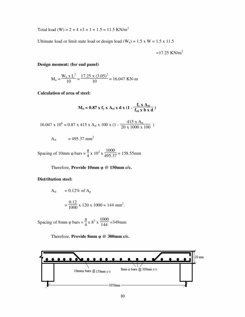
Therefore, Provide 10mm φ @ 150mm c/c.
Distribution steel:
Ast = 0.12% of Ag
= 0.12
1000 x 120 x 1000 = 144 mm
2.
Spacing of 8mm φ bars = π4 x 82 x
1000
144 =349mm
Therefore, Provide 8mm φ @ 300mm c/c.
31
Area of steel at support next to end support (between S5 (a) and S5 (b)):
From IS 456-2000, moment = Wu x L
2
10
Total Load acting on the support (Wu) = 17.25
2 +
17.25
2 = 17.25 KN/m
Therefore, Moment = 17.25 x (3.05)
2
10 = 16.05 KN-m
Calculation of Ast:
Mu = 0.87 x fy x Ast x d x (1 - fy x Ast
fck x b x d )
16.05 x 106 = 0.87 x 415 x Ast x 100 x (1 -
415 x Ast
20 x 1000 x 100 )
Ast = 495.47 mm2
Area of steel available by bending up the alternate bars of mid span steel:
From Slab S5 (a) = 1
2 x 404.27 = 202.135 mm
2
From Slab S5 (b) = 1
2 x 495.47 = 247.735 mm2
Total Ast (available) = 202.135 + 247.735 = 449.87 mm2
Therefore, extra bars required for Ast = 495.47 – 449.87 = 45.6 mm2
DESIGN OF FLOOR SLAB (S6 (a)):
D = 3.05 x 10
3
36.4 + 20 = 103.79mm say 120 mm
Effective depth (d) = D – d1 = 120 – 20 = 100mm
Loads:
Dead loads (From IS875 – Part 1):
Floor finish = 1 KN/m2

32
Self weight of the slab = 1 x 1 x D x 25 = 120
1000 x 25
= 3 KN/m2
Live loads (From IS875 – Part 2):
Office = 4 KN/m2
Total load (W) = 4 +3 + 1 = 8 KN/m2
Ultimate load or limit state load or design load (Wu) = 1.5 x W = 1.5 x 8
=12 KN/m2
Design moment: (for end panel)
Mu = Wu x L2
10 =
12 x (3.05)2
10 = 11.163 KN-m
Calculation of area of steel:
Mu = 0.87 x fy x Ast x d x (1 - fy x Ast
fck x b x d )
11.163 x 106 = 0.87 x 415 x Ast x 100 x (1 -
415 x Ast
20 x 1000 x 100 )
Ast = 332.06 mm2
Spacing of 10mm φ bars = π4
x 102 x
1000
332.06 = 236.53mm
Therefore, Provide 10mm φ @ 230mm c/c.
Distribution steel:
Ast = 0.12% of Ag
= 0.12
1000 x 120 x 1000 = 144 mm2.
Spacing of 8mm φ bars = π4 x 8
2 x
1000
144 =349mm

33
Therefore, Provide 8mm φ @ 300mm c/c.
DESIGN OF FLOOR SLAB (S6 (b)):
D = 3.05 x 10³
36.4 + 20 = 103.79mm say 120 mm
Effective depth (d) = D – d1 = 120 – 20 = 100mm
Loads:
Dead loads (From IS875 – Part 1):
Floor finish = 1 KN/m2
Self weight of the slab = 1 x 1 x D x 25 = 120
1000 x 25
= 3 KN/m2
Live loads (From IS875 – Part 2):
Office = 4 KN/m2
Total load (W) = 4 +3 + 1 = 8 KN/m2
Ultimate load or limit state load or design load (Wu) = 1.5 x W = 1.5 x 8
=12 KN/m2
Design moment: (for end panel)
Mu = Wu x L
2
12 =
12 x (3.05)2
12 = 9.3025 KN-m
34
Calculation of area of steel:
Mu = 0.87 x fy x Ast x d x (1 - fy x Ast
fck x b x d )
9.3025 x 106 = 0.87 x 415 x Ast x 100 x (1 - 415 x Ast
20 x 1000 x 100 )
Ast = 273.13 mm2
Spacing of 10mm φ bars = π4
x 102 x 1000
273.13 = 287.55mm
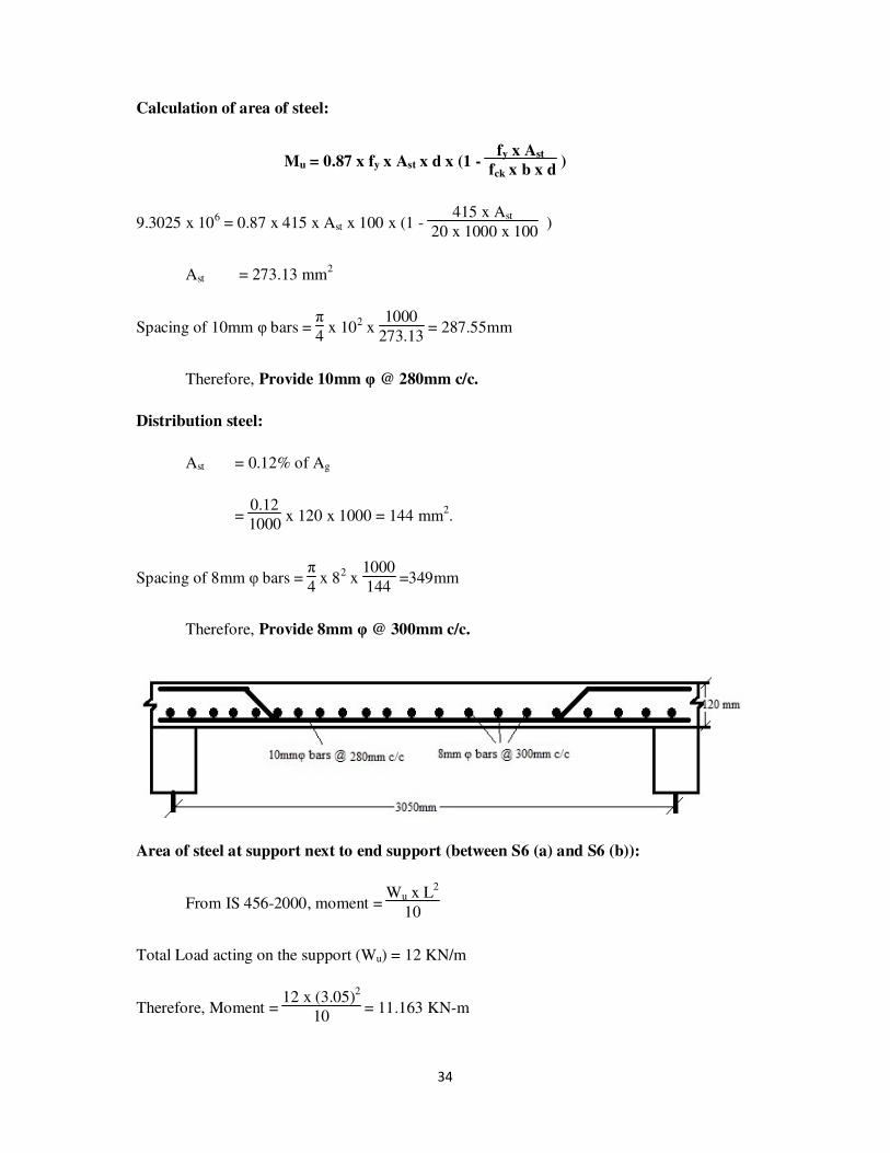
Therefore, Provide 10mm φ @ 280mm c/c.
Distribution steel:
Ast = 0.12% of Ag
= 0.12
1000 x 120 x 1000 = 144 mm
2.
Spacing of 8mm φ bars = π4 x 82 x
1000
144 =349mm
Therefore, Provide 8mm φ @ 300mm c/c.
Area of steel at support next to end support (between S6 (a) and S6 (b)):
From IS 456-2000, moment = Wu x L
2
10
Total Load acting on the support (Wu) = 12 KN/m
Therefore, Moment = 12 x (3.05)
2
10 = 11.163 KN-m

35
Calculation of Ast:
Mu = 0.87 x fy x Ast x d x (1 - fy x Ast
fck x b x d )
11.163 x 106 = 0.87 x 415 x Ast x 100 x (1 - 415 x Ast
20 x 1000 x 100 )
Ast = 332.06 mm2
Area of steel available by bending up the alternate bars of mid span steel:
From Slab S6 (a) = 1
2 x 332.06 = 166.03 mm
2
From Slab S6 (b) = 1
2 x 273.23 = 136.565 mm2
Total Ast (available) = 166.03 + 136.565 = 302.595 mm2
Therefore, extra bars required for Ast = 332.06 – 302.595 = 29.465 mm2
DESIGN OF FLOOR SLAB (S7):
D = 3.05 x 10
3
36.4 + 20 = 103.79mm say 120 mm
Effective depth (d) = D – d1 = 120 – 20 = 100mm
Loads:
Dead loads (From IS875 – Part 1):
Floor finish = 1 KN/m2
Self weight of the slab = 1 x 1 x D x 25 = 120
1000 x 25
= 3 KN/m2
Live loads (From IS875 – Part 2):
Library = 10 KN/m2
Total load (W) = 10 +3 + 1 = 14 KN/m2
36
Ultimate load or limit state load or design load (Wu) = 1.5 x W = 1.5 x 14
=21 KN/m2
Design moment: (for end panel)
Mu = Wu x L2
10 =
12 x (3.05)2
10 = 19.54 KN-m
Calculation of area of steel:
Mu = 0.87 x fy x Ast x d x (1 - fy x Ast
fck x b x d )
19.54 x 106 = 0.87 x 415 x Ast x 100 x (1 -
415 x Ast
20 x 1000 x 100 )
Ast = 621.3 mm2
Spacing of 10mm φ bars = π4
x 102 x
1000
621.3 = 126.41mm
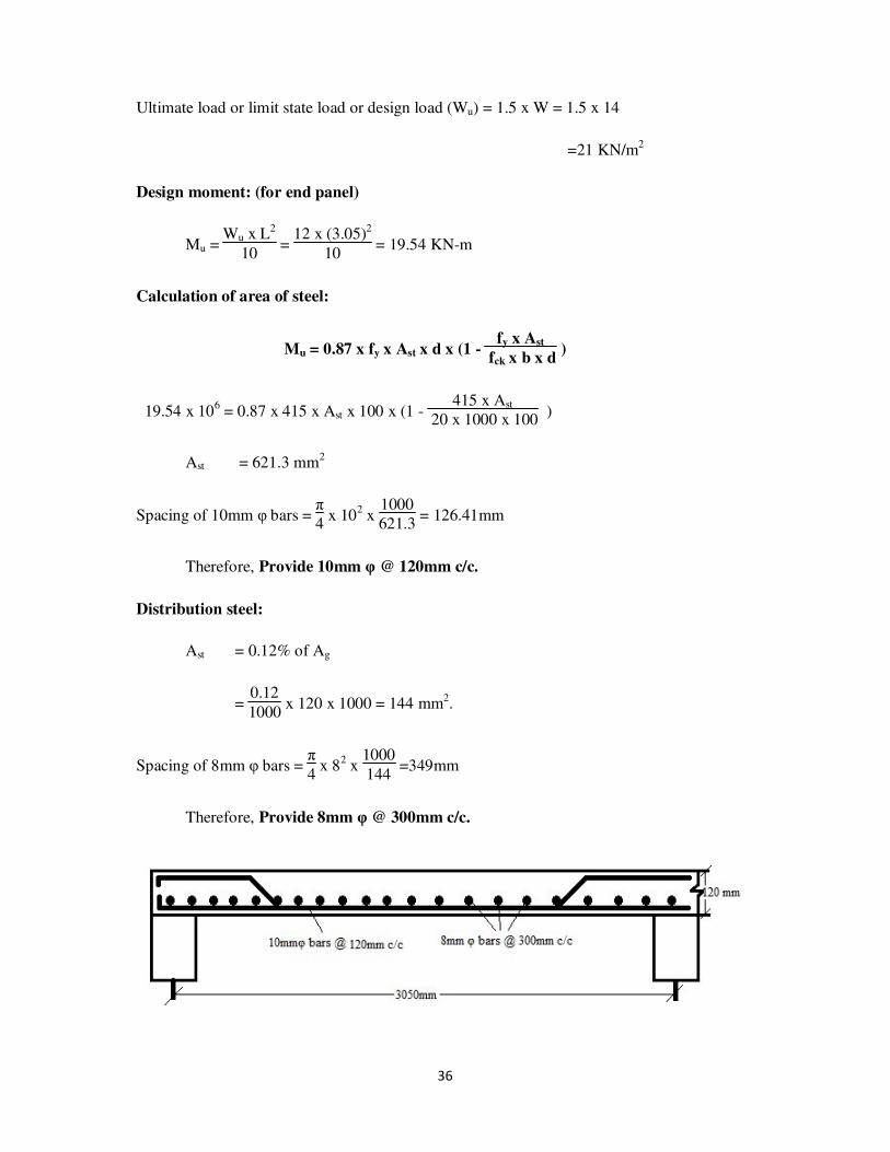
Therefore, Provide 10mm φ @ 120mm c/c.
Distribution steel:
Ast = 0.12% of Ag
= 0.12
1000 x 120 x 1000 = 144 mm2.
Spacing of 8mm φ bars = π4 x 8
2 x
1000
144 =349mm
Therefore, Provide 8mm φ @ 300mm c/c.

37
DESIGN OF FLOOR SLAB (S8):
D = 3.05 x 10
3
36.4 + 20 = 103.79mm say 120 mm
Effective depth (d) = D – d1 = 120 – 20 = 100mm
Loads:
Dead loads (From IS875 – Part 1):
Floor finish = 1 KN/m2
Self weight of the slab = 1 x 1 x D x 25 = 120
1000 x 25
= 3 KN/m2
Live loads (From IS875 – Part 2):
Private = 2 KN/m2
Total load (W) = 2 +3 + 1 = 6 KN/m2
Ultimate load or limit state load or design load (Wu) = 1.5 x W = 1.5 x 6
= 9 KN/m2
Design moment:
Mu = Wu x L2
12 =
9 x (3.05)2
12 = 6.97 KN-m
Calculation of area of steel:
Mu = 0.87 x fy x Ast x d x (1 - fy x Ast
fck x b x d )
6.97 x 106 = 0.87 x 415 x Ast x 100 x (1 -
415 x Ast
20 x 1000 x 100 )
Ast = 201.47 mm2
Spacing of 10mm φ bars = π4
x 102 x
1000
201.47 = 389.8mm

38
Therefore, Provide 10mm φ @ 300mm c/c.
Distribution steel:
Ast = 0.12% of Ag
= 0.12
1000 x 120 x 1000 = 144 mm2.
Spacing of 8mm φ bars = π4 x 8
2 x
1000
144 =349mm
Therefore, Provide 8mm φ @ 300mm c/c.
Area of steel at support next to end support (between S7and S8):
From IS 456-2000, moment = Wu x L2
10
Total Load acting on the support (Wu) = 21
2 +
9
2 = 15 KN/m
Therefore, Moment = 15 x (3.05)
2
10 = 13.95 KN-m
Calculation of Ast:
Mu = 0.87 x fy x Ast x d x (1 - fy x Ast
fck x b x d )
13.95 x 106 = 0.87 x 415 x Ast x 100 x (1 - 415 x Ast
20 x 1000 x 100 )
Ast = 423.61 mm2
Area of steel available by bending up the alternate bars of mid span steel:
39
From Slab S7 = 1
2 x 621.3 = 310.65 mm2
From Slab S8 = 1
2 x 201.47 = 100.735 mm
2
Total Ast (available) = 310.65 + 100.735 = 411.385 mm2
Therefore, extra bars required for Ast = 423.61 – 411.385 = 12.225 mm2
DESIGN OF FLOOR SLAB (S9 (a)):
D = 3.05 x 10
3
36.4 + 20 = 103.79mm say 120 mm
Effective depth (d) = D – d1 = 120 – 20 = 100mm
Loads:
Dead loads (From IS875 – Part 1):
Floor finish = 1 KN/m2
Self weight of the slab = 1 x 1 x D x 25 = 120
1000 x 25
= 3 KN/m2
Live loads (From IS875 – Part 2):
Office chamber = 3 KN/m2
Total load (W) = 3 +3 + 1 = 7 KN/m2
Ultimate load or limit state load or design load (Wu) = 1.5 x W = 1.5 x 7
= 10.5 KN/m2
Design moment:
Mu = Wu x L
2
12 =
10.5 x (3.05)2
12 = 8.14 KN-m

40
Calculation of area of steel:
Mu = 0.87 x fy x Ast x d x (1 - fy x Ast
fck x b x d )
8.14 x 106 = 0.87 x 415 x Ast x 100 x (1 - 415 x Ast
20 x 1000 x 100 )
Ast = 237.12 mm2
Spacing of 10mm φ bars = π4
x 102 x 1000
237.12 = 331.23mm
Therefore, Provide 10mm φ @ 300mm c/c.
Distribution steel:
Ast = 0.12% of Ag
= 0.12
1000 x 120 x 1000 = 144 mm
2.
Spacing of 8mm φ bars = π4 x 82 x
1000
144 =349mm
Therefore, Provide 8mm φ @ 300mm c/c.
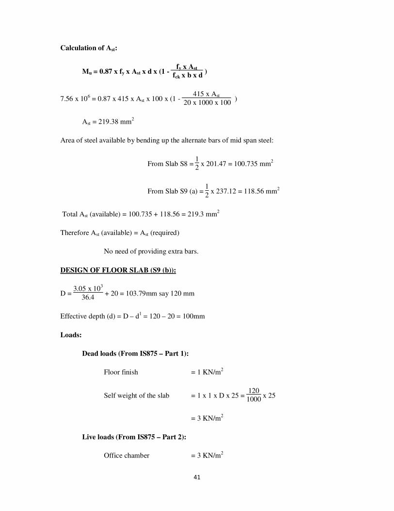
Area of steel at any other interior support: (Between S8 and S9 (a))
From IS 456-2000, moment = Wu x L
2
12
Total Load acting on the support (Wu) = 9
2 +
10.5
2 = 9.75 KN/m
Therefore, Moment = 9.75 x (3.05)2
12 = 7.56 KN-m
41
Calculation of Ast:
Mu = 0.87 x fy x Ast x d x (1 - fy x Ast
fck x b x d )
7.56 x 106 = 0.87 x 415 x Ast x 100 x (1 - 415 x Ast
20 x 1000 x 100 )
Ast = 219.38 mm2
Area of steel available by bending up the alternate bars of mid span steel:
From Slab S8 = 1
2 x 201.47 = 100.735 mm
2
From Slab S9 (a) = 1
2 x 237.12 = 118.56 mm2
Total Ast (available) = 100.735 + 118.56 = 219.3 mm2
Therefore Ast (available) = Ast (required)
No need of providing extra bars.
DESIGN OF FLOOR SLAB (S9 (b)):
D = 3.05 x 10
3
36.4 + 20 = 103.79mm say 120 mm
Effective depth (d) = D – d1 = 120 – 20 = 100mm
Loads:
Dead loads (From IS875 – Part 1):
Floor finish = 1 KN/m2
Self weight of the slab = 1 x 1 x D x 25 = 120
1000 x 25
= 3 KN/m2
Live loads (From IS875 – Part 2):
Office chamber = 3 KN/m2

42
Total load (W) = 3 +3 + 1 = 7 KN/m2
Ultimate load or limit state load or design load (Wu) = 1.5 x W = 1.5 x 7
= 10.5 KN/m2
Design moment: (for end panel)
Mu = Wu x L
2
10 =
10.5 x (3.05)2
10 = 9.77 KN-m
Calculation of area of steel:
Mu = 0.87 x fy x Ast x d x (1 - fy x Ast
fck x b x d )
9.77 x 106 = 0.87 x 415 x Ast x 100 x (1 - 415 x Ast
20 x 1000 x 100 )
Ast = 287.79 mm2
Spacing of 10mm φ bars = π4
x 102 x 1000
287.79 = 272.91mm
Therefore, Provide 10mm φ @ 270mm c/c.
Distribution steel:
Ast = 0.12% of Ag
= 0.12
1000 x 120 x 1000 = 144 mm
2.
Spacing of 8mm φ bars = π4 x 82 x
1000
144 =349mm
Therefore, Provide 8mm φ @ 300mm c/c.
43
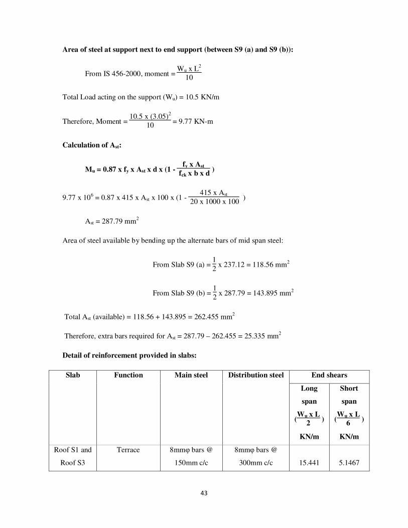
Area of steel at support next to end support (between S9 (a) and S9 (b)):
From IS 456-2000, moment = Wu x L
2
10
Total Load acting on the support (Wu) = 10.5 KN/m
Therefore, Moment = 10.5 x (3.05)
2
10 = 9.77 KN-m
Calculation of Ast:
Mu = 0.87 x fy x Ast x d x (1 - fy x Ast
fck x b x d )
9.77 x 106 = 0.87 x 415 x Ast x 100 x (1 - 415 x Ast
20 x 1000 x 100 )
Ast = 287.79 mm2
Area of steel available by bending up the alternate bars of mid span steel:
From Slab S9 (a) = 1
2 x 237.12 = 118.56 mm2
From Slab S9 (b) = 1
2 x 287.79 = 143.895 mm2
Total Ast (available) = 118.56 + 143.895 = 262.455 mm2
Therefore, extra bars required for Ast = 287.79 – 262.455 = 25.335 mm2
Detail of reinforcement provided in slabs:
Slab Function Main steel Distribution steel End shears
Long
span
(Wu x L
2 )
KN/m
Short
span
(Wu x L
6 )
KN/m
Roof S1 and
Roof S3
Terrace 8mmφ bars @
150mm c/c
8mmφ bars @
300mm c/c
15.441
5.1467

44
Roof S2 and
Roof S4
Terrace 8mmφ bars @
190mm c/c
8mmφ bars @
300mm c/c
15.441
5.1467
Floor S1 Toilet 10mmφ bars @
130mm c/c
8mmφ bars @
300mm c/c
29.738 9.913
Floor S2 Office 10mmφ bars @
210mm c/c
8mmφ bars @
300mm c/c
24.019 8
Floor S3 Office SupDt. 10mmφ bars @
210mm c/c
8mmφ bars @
300mm c/c
24.019 8
Floor S4 Assembly Hall 10mmφ bars @
210mm c/c
8mmφ bars @
300mm c/c
24.019 8
Floor S5 (a) Office chamber
and Waiting space
10mmφ bars @
190mm c/c
8mmφ bars @
300mm c/c
26.306
8.77
Floor S5 (b) Office chamber
and Waiting space
10mmφ bars @
150mm c/c
8mmφ bars @
300mm c/c
26.306
8.77
Floor S6 (a) Office 10mmφ bars @
230mm c/c
8mmφ bars @
300mm c/c
18.3 6.1
Floor S6 (b) Office 10mmφ bars @
280mm c/c
8mmφ bars @
300mm c/c
18.3 6.1
Floor S7 Library 10mmφ bars @
120mm c/c
8mmφ bars @
300mm c/c
32.025 10.675
Floor S8 Secretary room 10mmφ bars @
300mm c/c
8mmφ bars @
300mm c/c
13.725 4.575
Floor S9 (a) Office chamber 10mmφ bars @
300mm c/c
8mmφ bars @
300mm c/c
16.01 5.3375
Floor S9 (b) Office chamber 10mmφ bars @
270mm c/c
8mmφ bars @
300mm c/c
16.01 5.3375
45
3. Analysis of frames
We have many number frames from the plan and the need to be analysed. We have two
different types of frames:
1. Longitudinal direction frame
2. Transverse direction frame
Transverse frame:
The frames are chosen in such a way that the loads vary from one frame to the other and we
have 6 transverse frames.
i. Frame 19-10-01
ii. Frame 20-11-02
iii. Frame 24-15-06
iv. Frame 25-16-07
v. Frame 26-17-08
vi. Frame 27-18-09
In every frame we need to analyse the three types of loading cases and each frame consists of
roof and floor analysis.
Here we assumed the cross sections of beams and columns in advance and with the help of
the assumed dimensions, we calculate the stiffness of the members and there by the
distribution factors for the members especially at the joints.
To analyse the frame we use the substitute frame method and there by applying the moment
distribution method to know the moments carried by the member at the joints.
We take each floor span and we assume the top and bottom storeys are fixed by the substitute
frame principle.

46
Typical building frame:
We have G+5frame with all the details shown in the above figure.
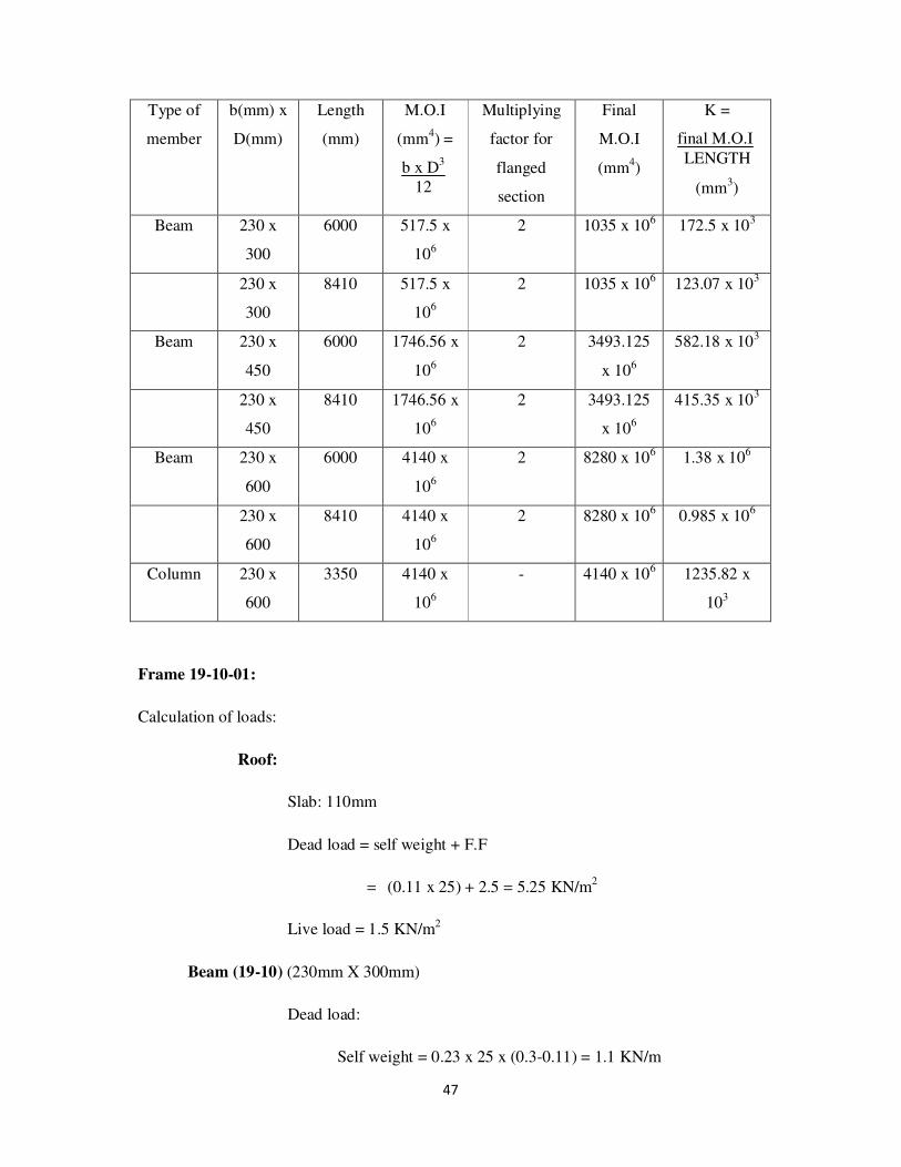
47
Type of
member
b(mm) x
D(mm)
Length
(mm)
M.O.I
(mm4) =
b x D3
12
Multiplying
factor for
flanged
section
Final
M.O.I
(mm4)
K =
final M.O.I
LENGTH
(mm3)
Beam 230 x
300
6000 517.5 x
106
2 1035 x 106 172.5 x 10³
230 x
300
8410 517.5 x
106
2 1035 x 106 123.07 x 10
3
Beam 230 x
450
6000 1746.56 x
106
2 3493.125
x 106
582.18 x 10³
230 x
450
8410 1746.56 x
106
2 3493.125
x 106
415.35 x 10³
Beam 230 x
600
6000 4140 x
106
2 8280 x 106 1.38 x 10⁶
230 x
600
8410 4140 x
106
2 8280 x 106 0.985 x 10
6
Column 230 x
600
3350 4140 x
106
- 4140 x 106 1235.82 x
103
Frame 19-10-01:
Calculation of loads:
Roof:
Slab: 110mm
Dead load = self weight + F.F
= (0.11 x 25) + 2.5 = 5.25 KN/m2
Live load = 1.5 KN/m2
Beam (19-10) (230mm X 300mm)
Dead load:
Self weight = 0.23 x 25 x (0.3-0.11) = 1.1 KN/m
48
Due to Slab = W x L
2 =
5.25 x 3.05
2 = 8 KN/m
250mm thick wall of 1m height = 0.25 x 1 x 20 = 5 KN/m
Live load:
Due to Slab = W x L
2 =
1.5 x 3.05
2 = 2.29KN/m
Therefore, Maximum load = 1.5 x (D.L + L.L) = 1.5 x (1.1 + 8 + 2.29 + 5)
= 24.6 KN/m
Minimum load = 0.9 x D.L = 0.9 x (1.1 + 8 + 5) = 13 KN/m
Beam (10-01) (230mm X 300mm)
Dead load:
Self weight = 0.23 x 25 x (0.3-0.11) = 1.1 KN/m
Due to Slab = W x L
2 =
5.25 x 3.05
2 = 8 KN/m
250mm thick wall of 1m height = 0.25 x 1 x 20 = 5 KN/m
Live load:
Due to Slab = W x L
2 =
1.5 x 3.05
2 = 2.29KN/m
Therefore, Maximum load = 1.5 x (D.L + L.L) = 1.5 x (1.1 + 8 + 2.29 + 5)
= 24.6 KN/m
Minimum load = 0.9 x D.L = 0.9 x (1.1 + 8 + 5) = 13 KN/m
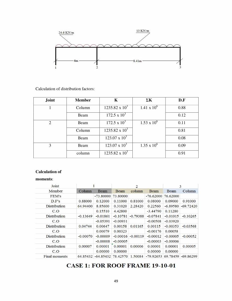
Case 1:
Maximum load on beam 19-10 and minimum load beam 10-01
49
Calculation of distribution factors:
Joint Member K ΣK D.F
1 Column 1235.82 x 103 1.41 x 10
6 0.88
Beam 172.5 x 10³ 0.12
2 Beam 172.5 x 10³ 1.53 x 10⁶ 0.11
Column 1235.82 x 103 0.81
Beam 123.07 x 10³ 0.08
3 Beam 123.07 x 10³ 1.35 x 10⁶ 0.09
column 1235.82 x 103 0.91
Calculation of
moments:

50
Calculation of support reactions:
From beam 1-2, ΣM1=0
64.85 + V2 x 6 = 24.6 x 6 x 6
2 + 78.52
V2 = 76.07 KN
V1 + V2 = 24.6 x 6 = 147.6 KN
V1 = 71.54 KN
Maximum Span moment,
X= 71.54
24.6 = 2.91m from the left support
Therefore, maximum moment = 71.54 x 2.91
2 - 64.85 = 39.24 KN-m
From beam 2-3, ΣM2=0
79.93 + V3 x 8.41 = 69.78 + 13 x 8.41 x 8.41
2
V3 = 53.46 KN
V2 + V3 = 13 x 8.41 =109.33 KN
V2 = 55.87 KN

51
Maximum Span moment,
X= 53.46
13 = 4.12m from the right support
Therefore, maximum moment = 53.46 x 4.12
2 - 69.78 = 40.35 KN-m
Case 2:
Minimum load on beam 19-10 and maximum load on 10-01
Distribution factors are same as calculate in case 1.
Calculation of moments:

52
Calculation of support reactions:
From beam 1-2, ΣM1=0
28.96 + V2 x 6 = 13 x 6 x 6
2 + 53.16
V2 = 42.87 KN
V1 + V2 = 13 x 6 = 78 KN
V1 = 35.13 KN
Maximum Span moment,
X= 35.13
13 = 2.7m from the left support
Therefore, maximum moment = 35.13 x 2.7
2 - 28.16 = 19.27 KN-m
From beam 2-3, ΣM2=0
142.85 + V3 x 8.41 = 136.01 + 24.6 x 8.41 x 8.41
2
V3 = 102.63 KN
V2 + V3 = 24.6 x 8.41 = 206.89 KN
V2 = 104.26 KN
Maximum Span moment,
X= 102.63
24.6 = 4.17m from the right support

53
Therefore, maximum moment = 102.63 x 4.17
2 - 136.01 = 77.97 KN-m
Case 3:
Max load on beam 19-10 and beam 10-01
Distribution factors are same as calculated in case 1.
Calculations of moments:

54
Calculation of support reactions:
From beam 1-2, ΣM1=0
61.38 + V2 x 6 = 24.6 x 6 x 6
2 + 86.09
V2 = 77.92 KN
V1 + V2 = 24.6 x 6 = 147.6 KN
V1 = 69.68 KN
Maximum Span moment,
X= 69.68
24.6 = 2.83m from the left support
Therefore, maximum moment = 69.68 x 2.83
2 - 61.38 = 37.22 KN-m
From beam 2-3, ΣM2=0
145.76 + V3 x 8.41 = 134.65 + 24.6 x 8.41 x 8.41
2
V3 = 102.05 KN
V2 + V3 = 24.6 x 8.41 = 206.89 KN
V2 = 104.84 KN
Maximum Span moment,
X= 102.05
24.6 = 4.15m from the right support
Therefore, maximum moment = 102.05 x 4.15
2 - 134.65 = 77.1 KN-m

55
Beam and column bending moments (KN-m):
Joint 1 Joint 2 Joint 3
Case Column Beam Max
span
moment
Beam Column Beam Max
span
moment
Beam Column
1 64.85 64.65 39.24 78.43 1.5 78.93 40.35 69.78 69.86
2 28.96 28.96 29.27 53.16 89.7 142.86 77.97 136.01 135.67
3 61.38 61.38 37.22 86.09 59.67 145.76 77.1 134.64 134.48
Max 64.85 64.65 39.24 86.09 89.7 145.76 77.97 136.01 135.67
Shear or support reaction (KN):
Case no. Joint 4 Joint 5 Joint 6
1 71.54 76.07 55.87 53.46
2 35.13 42.87 104.26 102.63
3 69.68 77.92 104.84 102.05
Maximum shear 71.54 77.92 104.84 102.63
Maximum column load 71.54 182.76 102.63
Floor:
Slab: 120mm
Dead load = self weight + F.F
= (0.12 x 25) + 1 = 4 KN/m2
Live load = 4 KN/m2 for Beam 19-10
= 5 KN/m2
for Beam 10-01
Beam (19-10) (230mm X 450mm)
Dead load:
Self weight = 0.23 x 25 x (0.45-0.12) = 1.9 KN/m

56
Due to Slab = W x L
2 =
4 x 3.05
2 = 6.1 KN/m
250mm thick wall = 0.25 x 20 x (3.35-0.3) = 15.25 KN/m
Live load:
Due to Slab = W x L
2 =
4 x 3.05
2 = 6.1KN/m
Therefore, Maximum load = 1.5 x (D.L + L.L) = 1.5 x (1.9+6.1+15.25+6.1)
= 44.025 KN/m
Minimum load = 0.9 x D.L = 0.9 x (1.9+6.1+15.25) = 21 KN/m
Beam (10-01) (230mm X 450mm)
Dead load:
Self weight = 0.23 x 25 x (0.45-0.12) = 1.9 KN/m
Due to Slab = W x L
2 =
4 x 3.05
2 = 6.1 KN/m
250mm thick wall = 0.25 x 20 x (3.35-0.3) = 15.25 KN/m
Live load:
Due to Slab = W x L
2 =
5 x 3.05
2 = 7.625KN/m
Therefore, Maximum load = 1.5 x (D.L + L.L) = 1.5 x (1.9+6.1+15.25+7.625)
= 46.5 KN/m
Minimum load = 0.9 x D.L = 0.9 x (1.9+6.1+15.25) = 21KN/m

57
Case 1:
Maximum load on beam 19-10 and minimum load on beam 10-01
Calculation of distribution factors:
Joint Member K ΣK D.F
4 Column 1235.82 x 103 3.05 x 10
6 0.4
Beam 582.18 x 10³ 0.2
Column 1235.82 x 103 0.4
5 Beam 582.18 x 10³ 3.47 x 10
6 0.17
Column 1235.82 x 103 0.36
Beam 415.35 x 10³ 0.11
Column 1235.82 x 103 0.36
6 Beam 415.35 x 10³ 2.89 x 10
6 0.14
Column 1235.82 x 103 0.43
Column 1235.82 x 103 0.43

58
Calculation of moments:
Calculation of support reactions:
From beam 4-5, ΣM4=0
106.54 + V5 x 6 = 44.025 x 6 x 6
2 + 143.19
V5 = 138.18 KN
V4 + V5 = 44.025 x 6 = 264.15 KN
V4 = 125.97 KN

59
Maximum Span moment,
X= 125.97
44.025 = 2.86m from the left support
Therefore, maximum moment = 125.96 x 2.86
2 - 106.54 = 73.58 KN-m
From beam 4-5, ΣM5=0
133.85 + V6 x 8.41 = 105.76 + 21 x 8.41 x 8.41
2
V6 = 84.96 KN
V5 + V6 = 21 x 8.41 = 176.61 KN
V5 = 91.65 KN
Maximum Span moment,
X= 84.96
21 = 4.05m from the right support
Therefore, maximum moment = 84.96 x 4.05
2 - 105.76 = 66.28 KN-m
Case 2:
Minimum load on beam 19-10 and maximum load on beam 10-01
Distribution factors are same as calculated in case-1.

60
Calculation of moments:
Calculation of support reactions:
From beam 4-5, ΣM4=0
34.99 + V5 x 6 = 21 x 6 x 6
2 + 105.91
V5 = 74.81 KN
V4 + V5 = 21 x 6 = 126 KN
V4 = 51.19 KN

61
Maximum Span moment,
X= 51.19
21 = 2.45m from the left support
Therefore, maximum moment = 51.19 x 2.45
2 - 34.99 = 27.72 KN-m
From beam 4-5, ΣM5=0
269.10 + V6 x 8.41 = 246.62 + 46.5 x 8.41 x 8.41
2
V6 = 192.86 KN
V5 + V6 = 46.5 x 8.41 = 391.07 KN
V5 = 198.21 KN
Maximum Span moment,
X= 192.86
46.5 = 4.15m from the right support
Therefore, maximum moment = 192.86 x 4.15
2 - 246.62= 153.57 KN-m
Case 3:
Maximum load on both beams
Distribution factors are same as calculated in case 1.

62
Calculation of moments:
Calculation of support reactions:
From beam 4-5, ΣM4=0
96.02 + V5 x 6 = 44.025 x 6 x 6
2 + 169.53
V5 = 144.33 KN
V4 + V5 = 44.025 x 6 = 264.15 KN
V4 = 119.82 KN
Maximum Span moment,
X= 119.82
44.025 = 2.72m from the left support

63
Therefore, maximum moment = 119.82 x 2.72
2 - 96.02 = 66.94 KN-m
From beam 4-5, ΣM5=0
277.32 + V6 x 8.41 = 242.87 + 46.5 x 8.41 x 8.41
2
V6 = 191.43 KN
V5 + V6 = 46.5 x 8.41 = 391.07 KN
V5 = 199.64 KN
Maximum Span moment,
X= 191.43
46.5 = 4.12m from the right support
Therefore, maximum moment = 191.43 x 4.12
2 - 242.87= 151.48 KN-m
Beam and column bending moments (KN-m):
Joint 4 Joint 5 Joint 6
Case Column Beam Max
span
moment
Beam Column Beam Max
span
moment
Beam Column
1 53.27 106.54 73.58 143.19 4.67 133.84 65.86 105.75 53.13
2 17.5 34.99 27.2 105.91 81.6 269.1 153.57 246.62 122.6
3 48.01 96.02 66.94 169.53 53.9 277.32 151.48 242.87 121.11
Max 53.27 106.54 73.58 169.53 81.6 277.32 153.57 246.62 122.6
Shear or support reaction (KN):
Case no. Joint 4 Joint 5 Joint 6
1 125.6 138.18 91.65 84.96
2 51.19 74.81 198.21 192.85
3 119.82 144.33 199.64 191.43
Maximum shear 125.6 144.33 199.64 192.85
Maximum column load 125.6 343.97 192.85

64
Frame 20-11-02:
Calculation of loads:
Roof:
Slab: 110mm
Dead load = self weight + F.F
= (0.11 x 25) + 2.5 = 5.25 KN/m2
Live load = 1.5 KN/m2
Beam (20-11) (230mm X 450mm)
Dead load:
Self weight = 0.23 x 25 x (0.45-0.11) = 1.2 KN/m
Due to Slab = W x L= 5.25 x 3.05= 16.0125 KN/m
Live load:
Due to Slab = W x L= 1.5 x 3.05= 4.6 KN/m
Therefore, Maximum load = 1.5 x (D.L + L.L) = 1.5 x (1.2+16.0125+4.6)
= 33 KN/m
Minimum load = 0.9 x D.L = 0.9 x (1.2+16.0125) = 15.49 KN/m
Beam (11-02) (230mm X 450mm)
Dead load:
Self weight = 0.23 x 25 x (0.45-0.11) = 1.2 KN/m
Due to Slab = W x L= 5.25 x 3.05= 16.0125 KN/m
Live load:
Due to Slab = W x L= 1.5 x 3.05= 4.6 KN/m

65
Therefore, Maximum load = 1.5 x (D.L + L.L) = 1.5 x (1.2+16.0125+4.6)
= 33 KN/m
Minimum load = 0.9 x D.L = 0.9 x (1.2+16.0125) = 15.49 KN/m
Case 1:
Maximum load on beam 20-11 and minimum load beam 11-02
Calculation of distribution factors:
Joint Member K ΣK D.F
1 Column 1235.82 x 103 1.818 x 10
6 0.68
Beam 582.18 x 10³ 0.32
2 Beam 582.18 x 10³ 2.234 x 10⁶ 0.26
Column 1235.82 x 103 0.55
Beam 415.35 x 10³ 0.19
3 Beam 415.35 x 10³ 1.651 x 10⁶ 0.25
column 1235.82 x 103 0.75

66
Calculation of moments:
Calculation of support reactions:
From beam 1-2, ΣM1=0
68.42 + V2 x 6 = 33 x 6 x 6
2 + 111.87
V2 = 106.24 KN
V1 + V2 = 33 x 6 = 198 KN
V1 = 91.76 KN

67
Maximum Span moment,
X= 91.76
33 = 2.78m from the left support
Therefore, maximum moment = 91.76 x 2.78
2 - 68.42 = 59.13 KN-m
From beam 2-3, ΣM2=0
105.03 + V3 x 8.41 = 67.38 + 15.49 x 8.41 x 8.41
2
V3 = 60.66 KN
V2 + V3 = 15.49 x 8.41 =130.27 KN
V2 = 69.61 KN
Maximum Span moment,
X= 60.66
15.49 = 3.92m from the right support
Therefore, maximum moment = 60.66 x 3.92
2 - 67.38 = 51.51 KN-m
Case 2:
Minimum load on beam 20-11 and maximum load on 11-02
Distribution factors are same as calculate in case 1.

68
Calculation of moments:
Calculation of support reactions:
From beam 1-2, ΣM1=0
16.56 + V2 x 6 = 15.49 x 6 x 6
2 + 94.59
V2 = 59.48 KN
V1 + V2 = 15.49 x 6 = 92.94 KN
V1 = 33.46 KN

69
Maximum Span moment,
X= 33.46
15.49 = 2.16m from the left support
Therefore, maximum moment = 33.46 x 2.16
2 - 16.56 = 19.58 KN-m
From beam 2-3, ΣM2=0
188.13 + V3 x 8.41 = 158.87 + 33 x 8.41 x 8.41
2
V3 = 135.28 KN
V2 + V3 = 33 x 8.41 = 277.53 KN
V2 = 142.25 KN
Maximum Span moment,
X= 135.28
33 = 4.1m from the right support
Therefore, maximum moment = 135.28 x 4.1
2 - 158.81 = 118.52 KN-m
Case 3:
Max load on beam 20-11 and beam 11-02
Distribution factors are same as calculated in case 1.
Calculations of moments:

70
Calculation of support reactions:
From beam 1-2, ΣM1=0
57.83 + V2 x 6 = 33 x 6 x 6
2 + 140.51
V2 = 112.78 KN
V1 + V2 = 33 x 6 = 198 KN
V1 = 85.22 KN
Maximum Span moment,
X= 85.22
33 = 2.58m from the left support

71
Therefore, maximum moment = 85.22 x 2.58
2 - 57.83 = 52.1 KN-m
From beam 2-3, ΣM2=0
199.52 + V3 x 8.41 = 153.93 + 33 x 8.41 x 8.41
2
V3 = 133.34 KN
V2 + V3 = 33 x 8.41 = 277.53 KN
V2 = 144.19 KN
Maximum Span moment,
X= 133.34
33 = 4.04m from the right support
Therefore, maximum moment = 133.34 x 4.04
2 - 153.93 = 115.42 KN-m
Beam and column bending moments (KN-m):
Joint 1 Joint 2 Joint 3
Case Column Beam Max
span
moment
Beam Column Beam Max
span
moment
Beam Column
1 68.42 68.42 59.13 111.87 6.84 105.0 51.51 67.38 68.22
2 16.58 16.58 19.58 94.59 93.54 188.13 118.52 158.81 155.58
3 57.85 57.83 52.1 140.51 59 199.51 115.42 153.93 152.3
Max 68.42 68.42 59.13 140.51 93.54 199.51 118.52 158.81 155.58
Shear or support reaction (KN):
Case no. Joint 4 Joint 5 Joint 6
1 91.76 106.24 69.61 60.66
2 33.46 59.48 142.25 135.28
3 85.22 112.78 144.11 133.34
Maximum shear 91.76 112.78 144.11 135.28
Maximum column load 91.76 256.89 135.28

72
Floor:
Slab: 120mm
Dead load = self weight + F.F
= (0.12 x 25) + 1 = 4 KN/m2
Live load = 4 KN/m2 for Beam 20-11
= 5 KN/m2
for Beam 11-02
Beam (20-11) (230mm X 600mm)
Dead load:
Self weight = 0.23 x 25 x (0.6-0.12) = 2.76 KN/m
Due to Slab = W x L= 4 x 3.05= 12.2 KN/m
Live load:
Due to Slab = W x L= 4 x 3.05= 12.2 KN/m
Therefore, Maximum load = 1.5 x (D.L + L.L) = 1.5 x (2.76+12.2+12.2)
= 41 KN/m
Minimum load = 0.9 x D.L = 0.9 x (2.76+12.2) = 13.5 KN/m
Beam (11-02) (230mm X 600mm)
Dead load:
Self weight = 0.23 x 25 x (0.6-0.12) = 2.76 KN/m
Due to Slab = W x L= 4 x 3.05= 12.2 KN/m
250mm thick wall = 0.25 x 20 x (3.35-0.45) = 14.5 KN/m
Live load:
Due to Slab = W x L= 5 x 3.05= 15.25KN/m
73
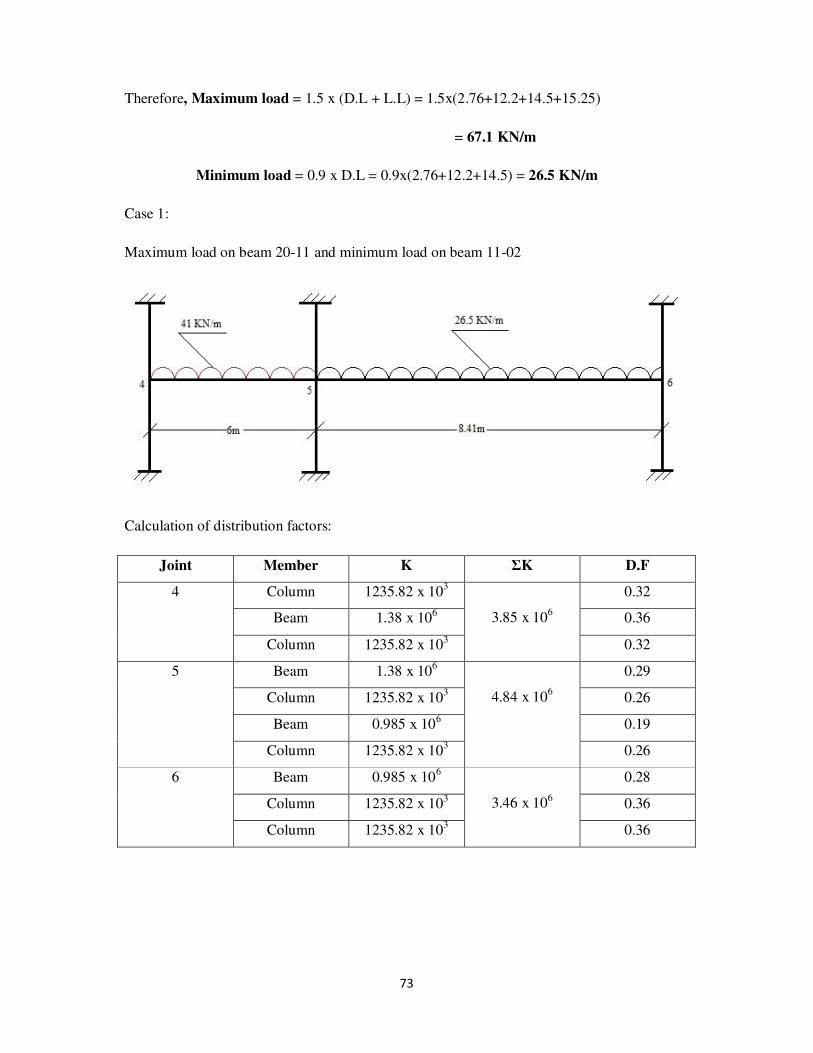
Therefore, Maximum load = 1.5 x (D.L + L.L) = 1.5x(2.76+12.2+14.5+15.25)
= 67.1 KN/m
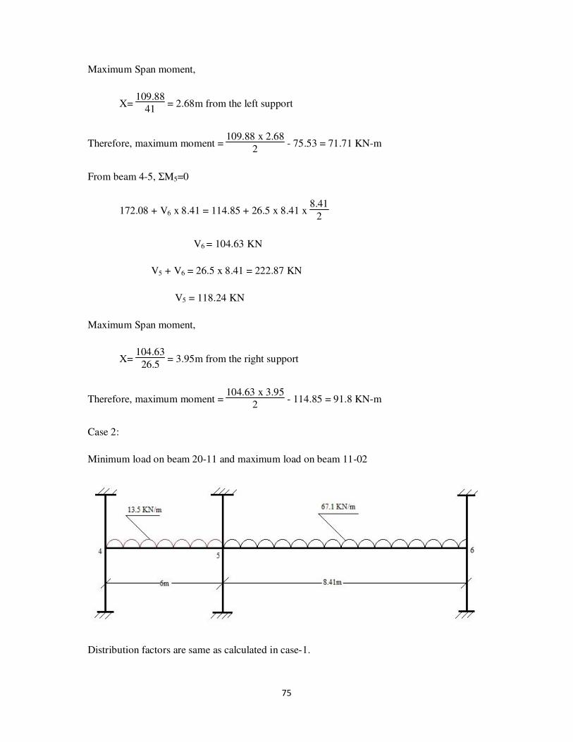
Minimum load = 0.9 x D.L = 0.9x(2.76+12.2+14.5) = 26.5 KN/m
Case 1:
Maximum load on beam 20-11 and minimum load on beam 11-02
Calculation of distribution factors:
Joint Member K ΣK D.F
4 Column 1235.82 x 103
3.85 x 10⁶
0.32
Beam 1.38 x 10⁶ 0.36
Column 1235.82 x 103 0.32
5 Beam 1.38 x 10⁶
4.84 x 10⁶
0.29
Column 1235.82 x 103 0.26
Beam 0.985 x 10⁶ 0.19
Column 1235.82 x 103 0.26
6 Beam 0.985 x 10⁶
3.46 x 10⁶
0.28
Column 1235.82 x 103 0.36
Column 1235.82 x 103 0.36
74
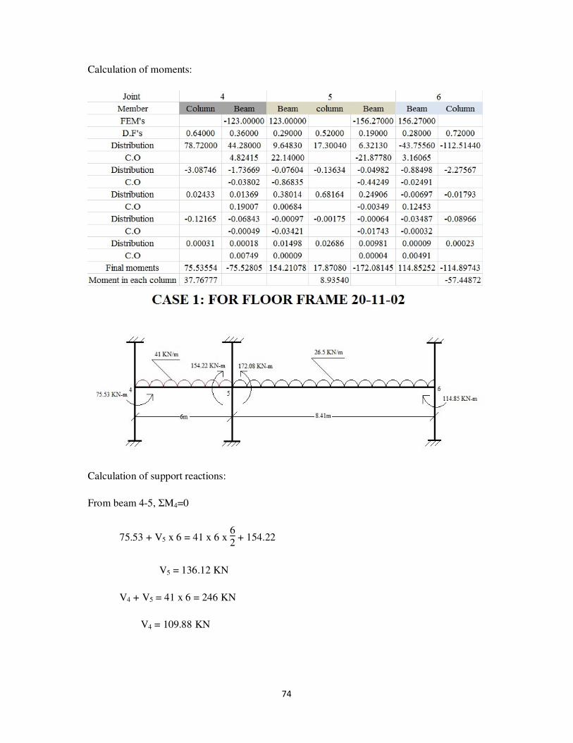
Calculation of moments:
Calculation of support reactions:
From beam 4-5, ΣM4=0
75.53 + V5 x 6 = 41 x 6 x 6
2 + 154.22
V5 = 136.12 KN
V4 + V5 = 41 x 6 = 246 KN
V4 = 109.88 KN
75
Maximum Span moment,
X= 109.88
41 = 2.68m from the left support
Therefore, maximum moment = 109.88 x 2.68
2 - 75.53 = 71.71 KN-m
From beam 4-5, ΣM5=0
172.08 + V6 x 8.41 = 114.85 + 26.5 x 8.41 x 8.41
2
V6 = 104.63 KN
V5 + V6 = 26.5 x 8.41 = 222.87 KN
V5 = 118.24 KN
Maximum Span moment,
X= 104.63
26.5 = 3.95m from the right support
Therefore, maximum moment = 104.63 x 3.95
2 - 114.85 = 91.8 KN-m
Case 2:
Minimum load on beam 20-11 and maximum load on beam 11-02
Distribution factors are same as calculated in case-1.

76
Calculation of moments:
Calculation of support reactions:
From beam 4-5, ΣM4=0
16.29 + V5 x 6 = 13.5 x 6 x 6
2 + 158.17
V5 = 64.15 KN
V4 + V5 = 13.5 x 6 = 81 KN
V4 = 16.85 KN
Maximum Span moment,
X= 16.85
13.5 = 1.25m from the left support

77
Therefore, maximum moment = 16.85 x 1.25
2 - 12.92 = -2.39 KN-m
From beam 4-5, ΣM5=0
375.67 + V6 x 8.41 = 315.93 + 67.1 x 8.41 x 8.41
2
V6 = 275.05 KN
V5 + V6 = 67.1 x 8.41 = 564.31 KN
V5 = 289.26 KN
Maximum Span moment,
X= 275.05
67.1 = 4.1m from the right support
Therefore, maximum moment = 275.05 x 4.1
2 - 315.93= 247.92 KN-m
Case 3:
Maximum load on both beams
Distribution factors are same as calculated in case 1.

78
Calculation of moments:
Calculation of support reactions:
From beam 4-5, ΣM4=0
49.25 + V5 x 6 = 41 x 6 x 6
2 + 228.89
V5 = 152.94 KN
V4 + V5 = 41 x 6 = 246 KN
V4 = 93.06 KN
Maximum Span moment,
X= 93.06
41 = 2.27m from the left support

79
Therefore, maximum moment = 93.06 x 2.27
2 - 49.25 = 56.37 KN-m
From beam 4-5, ΣM5=0
393.9 + V6 x 8.41 = 308.24 + 67.1 x 8.41 x 8.41
2
V6 = 271.97 KN
V5 + V6 = 67.1 x 8.41 = 564.31 KN
V5 = 292.34 KN
Maximum Span moment,
X= 271.97
67.1 = 4.05m from the right support
Therefore, maximum moment = 271.97 x 4.05
2 - 308.24= 242.5 KN-m
Beam and column bending moments (KN-m):
Joint 4 Joint 5 Joint 6
Case Column Beam Max
span
moment
Beam Column Beam Max
span
moment
Beam Column
1 37.77 75.53 71.71 154.21 8.9 172.08 91.8 114.85 57.45
2 6.42 12.92 3.092 158.17 108.74 375.67 247.92 315.93 153.37
3 24.66 49.25 56.37 228.89 82.5 393.9 242.5 308.24 150.94
Max 37.77 75.53 71.71 228.89 108.74 393.9 247.92 315.93 153.37
Shear or support reaction (KN):
Case no. Joint 4 Joint 5 Joint 6
1 109.8 136.12 118.24 104.63
2 16.85 64.15 289.26 275.05
3 93.06 152.94 292.34 271.97
Maximum shear 109.8 152.94 292.34 275.05
Maximum column load 109.8 445.28 275.05

80
Frame 24-15-06
Roof:
Same as frame 20-11-02
Floor:
Slab = 120mm
Dead load = self weight + F.F
= (0.12 x 25) + 1 = 4 KN/m2
Live load = 10 KN/m2
for Beam 24-15
= 2 KN/m2 for Beam 24-15
= 5 KN/m2 for Beam 15-06
Beam (24-15) (230mm X 600mm)
Dead load:
Self weight = 0.23 x 25 x (0.6-0.12) = 2.76 KN/m
Due to Slab = W x L= 4 x 3.05= 12.2 KN/m
150mm wall of 2.2m height = 0.15 x 20 x 2.2 = 6.6 KN/m
Live load:
Due to Slab = 5 x 3.05
2 +
2 x 3.05
2 = 10.675 KN/m
Therefore, Maximum load = 1.5 x (D.L + L.L) = 1.5x(2.76+12.2+6.6+10.675)
= 48.5 KN/m
Minimum load = 0.9 x D.L = 0.9 x (2.76+12.2+6.6) = 19.5 KN/m

81
Beam (15-06) (230mm X 600mm)
Dead load:
Self weight = 0.23 x 25 x (0.6-0.12) = 2.76 KN/m
Due to Slab = W x L= 4 x 3.05= 12.2 KN/m
Live load:
Due to Slab = W x L= 5 x 3.05= 15.25KN/m
Therefore, Maximum load = 1.5 x (D.L + L.L) = 1.5 x (2.76+12.2+15.25)
= 45.5 KN/m
Minimum load = 0.9 x D.L = 0.9 x (2.76+12.2) = 22.5 KN/m
Case 1:
Maximum load on beam 24-15 and minimum load on beam 15-06

82
Calculation of distribution factors:
Joint Member K ΣK D.F
4 Column 1235.82 x 103
3.85 x 10⁶
0.32
Beam 1.38 x 10⁶ 0.36
Column 1235.82 x 103 0.32
5 Beam 1.38 x 10⁶
4.84 x 10⁶
0.29
Column 1235.82 x 103 0.26
Beam 0.985 x 10⁶ 0.19
Column 1235.82 x 103 0.26
6 Beam 0.985 x 10⁶
3.46 x 10⁶
0.28
Column 1235.82 x 103 0.36
Column 1235.82 x 103 0.36
Calculation of moments:
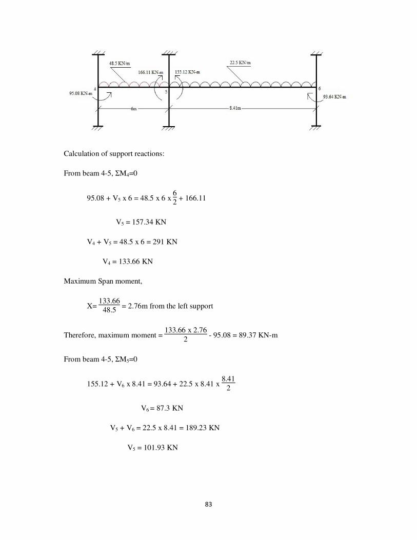
83
Calculation of support reactions:
From beam 4-5, ΣM4=0
95.08 + V5 x 6 = 48.5 x 6 x 6
2 + 166.11
V5 = 157.34 KN
V4 + V5 = 48.5 x 6 = 291 KN
V4 = 133.66 KN
Maximum Span moment,
X= 133.66
48.5 = 2.76m from the left support
Therefore, maximum moment = 133.66 x 2.76
2 - 95.08 = 89.37 KN-m
From beam 4-5, ΣM5=0
155.12 + V6 x 8.41 = 93.64 + 22.5 x 8.41 x 8.41
2
V6 = 87.3 KN
V5 + V6 = 22.5 x 8.41 = 189.23 KN
V5 = 101.93 KN

84
Maximum Span moment,
X= 87.3
22.5 = 3.88m from the right support
Therefore, maximum moment = 87.3 x 3.88
2 - 93.64 = 75.72 KN-m
Case 2:
Minimum load on beam 24-15 and maximum load on beam 15-06
Distribution factors are same as calculated in case-1.
Calculation of moments:

85
Calculation of support reactions:
From beam 4-5, ΣM4=0
14.68 + V5 x 6 = 19.5 x 6 x 6
2 + 133.86
V5 = 78.37 KN
V4 + V5 = 19.5 x 6 = 117 KN
V4 = 38.63 KN
Maximum Span moment,
X= 38.63
19.5 = 1.98m from the left support
Therefore, maximum moment = 38.63 x 1.98
2 - 14.68 = 23.56 KN-m
From beam 4-5, ΣM5=0
261.6 + V6 x 8.41 = 211.34 + 45.5 x 8.41 x 8.41
2
V6 = 185.35 KN
V5 + V6 = 45.5 x 8.41 = 382.66 KN
V5 = 197.31 KN

86
Maximum Span moment,
X= 185.35
45.5 = 4.07m from the right support
Therefore, maximum moment = 185.35 x 4.07
2 - 211.34= 165.85 KN-m
Case 3:
Maximum load on both beams
Distribution factors are same as calculated in case 1.
Calculation of moments:

87
Calculation of support reactions:
From beam 4-5, ΣM4=0
80.19 + V5 x 6 = 44.5 x 6 x 6
2 + 208.43
V5 = 166.87 KN
V4 + V5 = 48.5 x 6 = 291 KN
V4 = 124.13 KN
Maximum Span moment,
X= 124.13
48.5 = 2.56m from the left support
Therefore, maximum moment = 124.13 x 2.56
2 - 80.19 = 78.7 KN-m
From beam 4-5, ΣM5=0
280.82 + V6 x 8.41 = 203.22 + 45.5 x 8.41 x 8.41
2
V6 = 182.1 KN
V5 + V6 = 67.1 x 8.41 = 382.66 KN
V5 = 200.56 KN
Maximum Span moment,
X= 182.1
45.5 = 4m from the right support
88
Therefore, maximum moment = 182.1 x 4
2 - 203.22= 160.98 KN-m
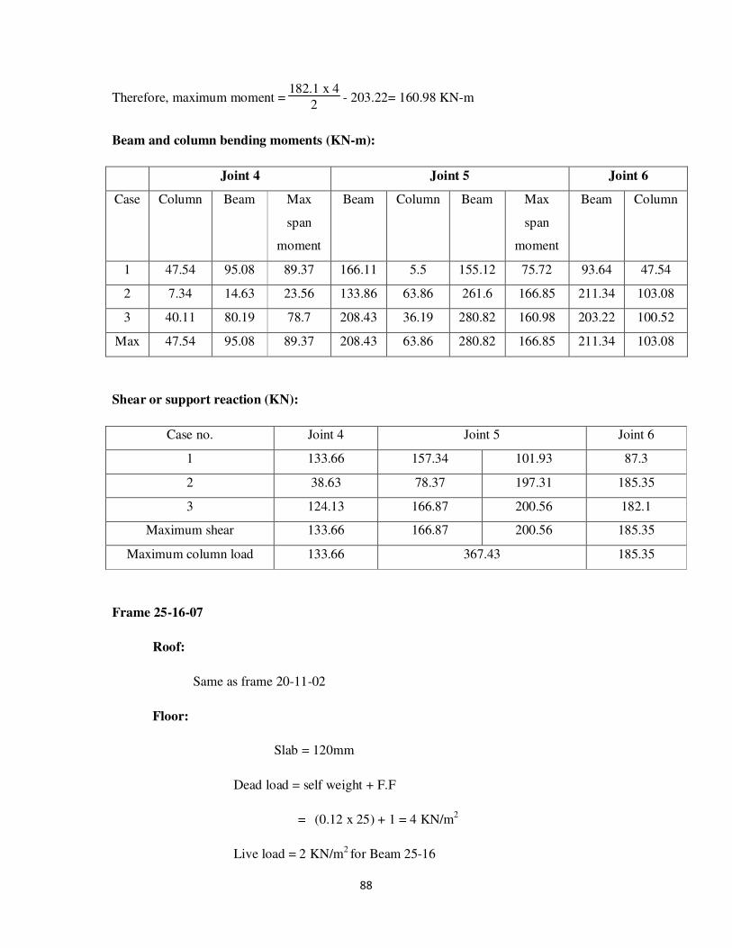
Beam and column bending moments (KN-m):
Joint 4 Joint 5 Joint 6
Case Column Beam Max
span
moment
Beam Column Beam Max
span
moment
Beam Column
1 47.54 95.08 89.37 166.11 5.5 155.12 75.72 93.64 47.54
2 7.34 14.63 23.56 133.86 63.86 261.6 166.85 211.34 103.08
3 40.11 80.19 78.7 208.43 36.19 280.82 160.98 203.22 100.52
Max 47.54 95.08 89.37 208.43 63.86 280.82 166.85 211.34 103.08
Shear or support reaction (KN):
Case no. Joint 4 Joint 5 Joint 6
1 133.66 157.34 101.93 87.3
2 38.63 78.37 197.31 185.35
3 124.13 166.87 200.56 182.1
Maximum shear 133.66 166.87 200.56 185.35
Maximum column load 133.66 367.43 185.35
Frame 25-16-07
Roof:
Same as frame 20-11-02
Floor:
Slab = 120mm
Dead load = self weight + F.F
= (0.12 x 25) + 1 = 4 KN/m2
Live load = 2 KN/m2 for Beam 25-16

89
= 4 KN/m2 for Beam 25-16
= 6 KN/m2
for Beam 16-07
= 5 KN/m2
for Beam 16-07
Beam (25-16) (230mm X 600mm)
Dead load:
Self weight = 0.23 x 25 x (0.6-0.12) = 2.76 KN/m
Due to Slab = W x L= 4 x 3.05= 12.2 KN/m
150mm wall of 2.2m height = 0.15 x 20 x 2.2 = 6.6 KN/m
Live load:
Due to Slab = 2 x 3.05
2 +
3 x 3.05
2 = 7.625 KN/m
Therefore, Maximum load = 1.5 x (D.L + L.L) = 1.5x(2.76+12.2+6.6+7.625)
= 44 KN/m
Minimum load = 0.9 x D.L = 0.9 x (2.76+12.2+6.6) = 19.5 KN/m
Beam (16-07) (230mm X 600mm)
Dead load:
Self weight = 0.23 x 25 x (0.6-0.12) = 2.76 KN/m
Due to Slab = W x L= 4 x 3.05= 12.2 KN/m
150mm wall of 2.2m height = 0.15 x 20 x 2.2 = 6.6 KN/m
Live load:
Due to Slab = 5 x 3.05
2 +
6 x 3.05
2 = 16.775 KN/m
Therefore, Maximum load = 1.5 x (D.L + L.L) = 1.5x(2.76+12.2+6.6+16.775)
= 57.51 KN/m

90
Minimum load = 0.9 x D.L = 0.9 x (2.76+12.2+6.6) = 21.3 KN/m
Case 1:
Maximum load on beam 25-16 and minimum load on beam 16-07
Calculation of distribution factors:
Joint Member K ΣK D.F
4 Column 1235.82 x 103
3.85 x 10⁶
0.32
Beam 1.38 x 10⁶ 0.36
Column 1235.82 x 103 0.32
5 Beam 1.38 x 10⁶
4.84 x 10⁶
0.29
Column 1235.82 x 103 0.26
Beam 0.985 x 10⁶ 0.19
Column 1235.82 x 103 0.26
6 Beam 0.985 x 10⁶
3.46 x 10⁶
0.28
Column 1235.82 x 103 0.36
Column 1235.82 x 103 0.36

91
Calculation of moments:
Calculation of support reactions:
From beam 4-5, ΣM4=0
85.69 + V5 x 6 = 44 x 6 x 6
2 + 152.33
V5 = 143.11 KN
V4 + V5 = 44 x 6 = 264 KN
V4 = 120.89 KN

92
Maximum Span moment,
X= 120.89
44 = 2.75m from the left support
Therefore, maximum moment = 120.89 x 2.75
2 - 85.69 = 80.45 KN-m
From beam 4-5, ΣM5=0
145.58 + V6 x 8.41 = 89.17 + 21.3 x 8.41 x 8.41
2
V6 = 82.86 KN
V5 + V6 = 21.3 x 8.41 = 179.13 KN
V5 = 96.27 KN
Maximum Span moment,
X= 82.86
21.3 = 3.89m from the right support
Therefore, maximum moment = 82.86 x 3.89
2 - 89.17 = 72 KN-m
Case 2:
Minimum load on beam 25-16 and maximum load on beam 16-07

93
Distribution factors are same as calculated in case-1.
Calculation of moments:
Calculation of support reactions:
From beam 4-5, ΣM4=0
6.85 + V5 x 6 = 19.5 x 6 x 6
2 + 155.96
V5 = 83.35 KN
V4 + V5 = 19.5 x 6 = 117 KN
V4 = 33.65 KN

94
Maximum Span moment,
X= 33.65
19.5 = 1.73m from the left support
Therefore, maximum moment = 33.65 x 1.73
2 - 6.85 = 22.26 KN-m
From beam 4-5, ΣM5=0
327.23 + V6 x 8.41 = 268.6 + 57.51 x 8.41 x 8.41
2
V6 = 234.86 KN
V5 + V6 = 57.51 x 8.41 = 483.66 KN
V5 = 248.8 KN
Maximum Span moment,
X= 234.86
57.51 = 4.08m from the right support
Therefore, maximum moment = 234.86 x 4.08
2 - 268.6= 210.5 KN-m
Case 3:
Maximum load on both beams
Distribution factors are same as calculated in case 1.

95
Calculation of moments:
Calculation of support reactions:
From beam 4-5, ΣM4=0
62.24 + V5 x 6 = 44 x 6 x 6
2 + 218.95
V5 = 158.11 KN
V4 + V5 = 48.5 x 6 = 264 KN
V4 = 105.89 K

96
Maximum Span moment,
X= 105.89
44 = 2.41m from the left support
Therefore, maximum moment = 105.89 x 2.41
2 - 62.24 = 65.36 KN-m
From beam 4-5, ΣM5=0
343.47 + V6 x 8.41 = 257.17 + 57.51 x 8.41 x 8.41
2
V6 = 231.56 KN
V5 + V6 = 67.1 x 8.41 = 483.66 KN
V5 = 252.1 KN
Maximum Span moment,
X= 231.56
57.51 = 4.03m from the right support
Therefore, maximum moment = 231.56 x 4.03
2 - 257.17= 209.42 KN-m
Beam and column bending moments (KN-m):
Joint 4 Joint 5 Joint 6
Case Column Beam Max
span
moment
Beam Column Beam Max
span
moment
Beam Column
1 42.84 85.69 80.45 152.33 3.38 145.56 72 89.17 45.17
2 3.46 6.85 22.26 155.96 85.63 327.23 210.5 268.55 130.75
3 31.15 62.24 65.36 218.95 62.25 343.47 209.42 261.7 128.6
Max 42.84 85.69 80.45 218.95 85.63 343.47 210.5 268.55 130.75
97
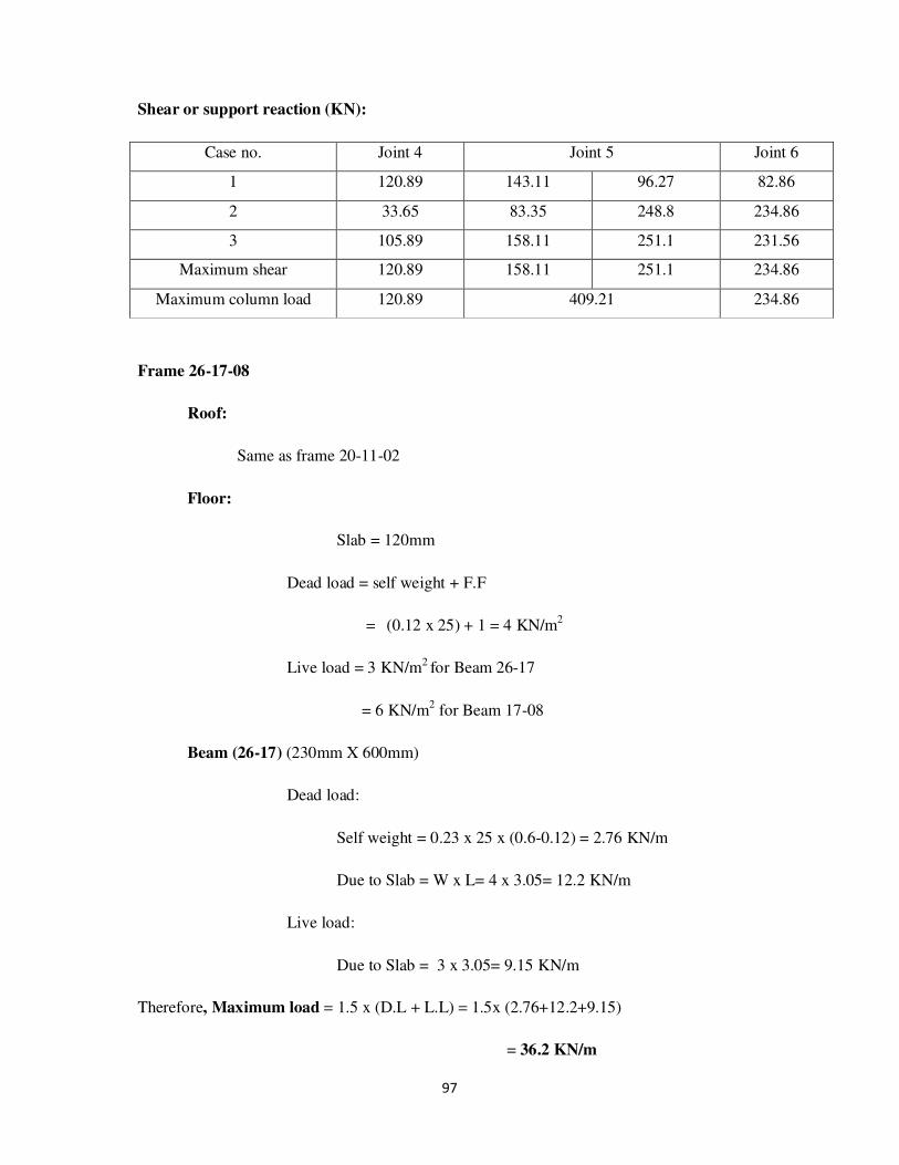
Shear or support reaction (KN):
Case no. Joint 4 Joint 5 Joint 6
1 120.89 143.11 96.27 82.86
2 33.65 83.35 248.8 234.86
3 105.89 158.11 251.1 231.56
Maximum shear 120.89 158.11 251.1 234.86
Maximum column load 120.89 409.21 234.86
Frame 26-17-08
Roof:
Same as frame 20-11-02
Floor:
Slab = 120mm
Dead load = self weight + F.F
= (0.12 x 25) + 1 = 4 KN/m2
Live load = 3 KN/m2 for Beam 26-17
= 6 KN/m2 for Beam 17-08
Beam (26-17) (230mm X 600mm)
Dead load:
Self weight = 0.23 x 25 x (0.6-0.12) = 2.76 KN/m
Due to Slab = W x L= 4 x 3.05= 12.2 KN/m
Live load:
Due to Slab = 3 x 3.05= 9.15 KN/m
Therefore, Maximum load = 1.5 x (D.L + L.L) = 1.5x (2.76+12.2+9.15)
= 36.2 KN/m

98
Minimum load = 0.9 x D.L = 0.9 x (2.76+12.2) = 13.5 KN/m
Beam (17-08) (230mm X 600mm)
Dead load:
Self weight = 0.23 x 25 x (0.6-0.12) = 2.76 KN/m
Due to Slab = W x L= 4 x 3.05= 12.2 KN/m
Live load:
Due to Slab = 6 x 3.05= 18.3 KN/m
Therefore, Maximum load = 1.5 x (D.L + L.L) = 1.5x (2.76+12.2+18.3)
= 50 KN/m
Minimum load = 0.9 x D.L = 0.9 x (2.76+12.2) = 13.5 KN/m
Case 1:
Maximum load on beam 26-17 and minimum load on beam 17-08

99
Calculation of distribution factors:
Joint Member K ΣK D.F
4 Column 1235.82 x 103
3.85 x 10⁶
0.32
Beam 1.38 x 10⁶ 0.36
Column 1235.82 x 103 0.32
5 Beam 1.38 x 10⁶
4.84 x 10⁶
0.29
Column 1235.82 x 103 0.26
Beam 0.985 x 10⁶ 0.19
Column 1235.82 x 103 0.26
6 Beam 0.985 x 10⁶
3.46 x 10⁶
0.28
Column 1235.82 x 103 0.36
Column 1235.82 x 103 0.36
Calculation of moments:

100
Calculation of support reactions:
From beam 4-5, ΣM4=0
73.1+ V5 x 6 = 36.2 x 6 x 6
2 + 117.93
V5 = 116.07 KN
V4 + V5 = 46.2 x 6 = 217.2 KN
V4 = 101.13 KN
Maximum Span moment,
X= 101.13
36.2 = 2.8m from the left support
Therefore, maximum moment = 101.13 x 2.8
2 - 73.1 = 68.48 KN-m
From beam 4-5, ΣM5=0
97.78 + V6 x 8.41 = 54.2 + 13.5 x 8.41 x 8.41
2
V6 = 51.59KN
V5 + V6 = 13.5 x 8.41 = 113.54 KN
V5 = 61.95 KN
Maximum Span moment,
X= 51.59
13.5 = 3.82m from the right support

101
Therefore, maximum moment = 51.59 x 3.82
2 - 54.2 = 44.34 KN-m
Case 2:
Minimum load on beam 26-17 and maximum load on beam 17-08
Distribution factors are same as calculated in case-1.
Calculation of moments:

102
Calculation of support reactions:
From beam 4-5, ΣM4=0
1.84 + V5 x 6 = 13.5 x 6 x 6
2 + 126.71
V5 = 61.31 KN
V4 + V5 = 13.5 x 6 = 81 KN
V4 = 19.69 KN
Maximum Span moment,
X= 19.69
13.5 = 1.46m from the left support
Therefore, maximum moment = 19.69 x 1.46
2 - 1.84 = 12.54 KN-m
From beam 4-5, ΣM5=0
282.21 + V6 x 8.41 = 234.45 + 50 x 8.41 x 8.41
2
V6 = 204.57 KN
V5 + V6 = 50 x 8.41 = 420.5 KN
V5 = 215.93 KN
Maximum Span moment,
X= 204.57
50 = 4.09m from the right support

103
Therefore, maximum moment = 204.57 x 4.09
2 - 234.45= 183.9 KN-m
Case 3:
Maximum load on both beams
Distribution factors are same as calculated in case 1.
Calculation of moments:

104
Calculation of support reactions:
From beam 4-5, ΣM4=0
49.5 + V5 x 6 = 36.2 x 6 x 6
2 + 185.08
V5 = 131.2 KN
V4 + V5 = 36.2 x 6 = 217.2 KN
V4 = 86 KN
Maximum Span moment,
X= 86
36.2 = 2.38m from the left support
Therefore, maximum moment = 86 x 2.38
2 - 49.5 = 52.84 KN-m
From beam 4-5, ΣM5=0
297.26 + V6 x 8.41 = 228.1 + 50 x 8.41 x 8.41
2
V6 = 202.03 KN
V5 + V6 = 50 x 8.41 = 420.5 KN
V5 = 218.47 KN
Maximum Span moment,
X= 202.03
50 = 4.04m from the right support

105
Therefore, maximum moment = 202.03 x 4.04
2 - 228.1= 180 KN-m
Beam and column bending moments (KN-m):
Joint 4 Joint 5 Joint 6
Case Column Beam Max
span
moment
Beam Column Beam Max
span
moment
Beam Column
1 36.55 73.1 68.48 117.93 10.07 97.78 44.34 54.2 27.9
2 0.9 1.85 12.54 126.71 77.74 282.21 183.9 234.45 113.98
3 24.76 49.5 52.84 185.08 56.08 297.26 180 228.1 111.97
Max 36.55 73.1 68.48 185.08 77.74 297.26 183.9 234.45 113.98
Shear or support reaction (KN):
Case no. Joint 4 Joint 5 Joint 6
1 101.13 116.07 61.95 51.59
2 19.69 61.31 215.93 204.57
3 86 131.2 218.47 202.03
Maximum shear 101.13 131.2 218.47 204.57
Maximum column load 101.13 349.67 204.57
Frame 27-18-09
Roof:
Same as of roof frame 19-10-01
Floor:
Slab: 120mm
Dead load = self weight + F.F
= (0.12 x 25) + 1 = 4 KN/m2
Live load = 3 KN/m2 for Beam 27-18

106
= 6 KN/m2 for Beam 18-09
Beam (27-18) (230mm X 450mm)
Dead load:
Self weight = 0.23 x 25 x (0.45-0.12) = 1.9 KN/m
Due to Slab = W x L
2 =
4 x 3.05
2 = 6.1 KN/m
250mm thick wall = 0.25 x 20 x (3.35-0.3) = 15.25 KN/m
Live load:
Due to Slab = W x L
2 =
3 x 3.05
2 = 4.6KN/m
Therefore, Maximum load = 1.5 x (D.L + L.L) = 1.5 x (1.9+6.1+15.25+4.6)
= 42 KN/m
Minimum load = 0.9 x D.L = 0.9 x (1.9+6.1+15.25) = 21 KN/m
Beam (18-09) (230mm X 450mm)
Dead load:
Self weight = 0.23 x 25 x (0.45-0.12) = 1.9 KN/m
Due to Slab = W x L
2 =
4 x 3.05
2 = 6.1 KN/m
250mm thick wall = 0.25 x 20 x (3.35-0.3) = 15.25 KN/m
Live load:
Due to Slab = W x L
2 =
6 x 3.05
2 = 9.15KN/m
Therefore, Maximum load = 1.5 x (D.L + L.L) = 1.5 x (1.9+6.1+15.25+9.15)
= 48.6 KN/m
Minimum load = 0.9 x D.L = 0.9 x (1.9+6.1+15.25) = 21KN/m

107
Case 1:
Maximum load on beam 27-18 and minimum load on beam 18-09
Calculation of distribution factors:
Joint Member K ΣK D.F
4 Column 1235.82 x 103 3.05 x 10⁶ 0.4
Beam 582.18 x 10³ 0.2
Column 1235.82 x 103 0.4
5 Beam 582.18 x 10³ 3.47 x 10⁶ 0.17
Column 1235.82 x 103 0.36
Beam 415.35 x 10³ 0.11
Column 1235.82 x 103 0.36
6 Beam 415.35 x 10³ 2.89 x 10⁶ 0.14
Column 1235.82 x 103 0.43
Column 1235.82 x 103 0.43
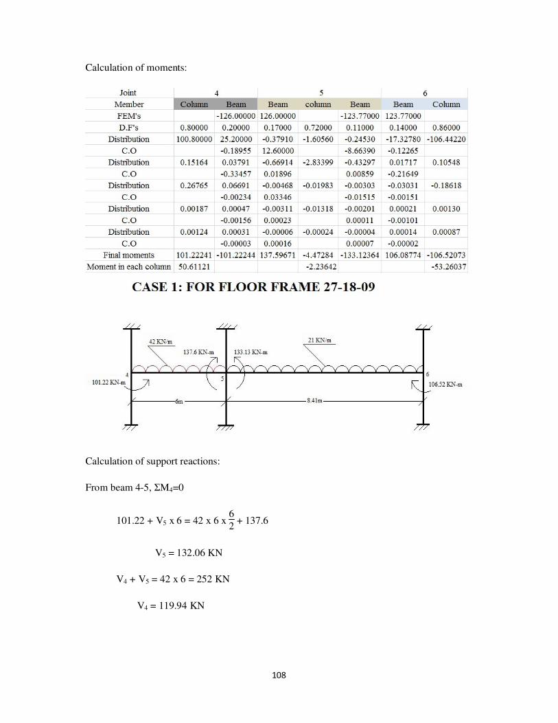
108
Calculation of moments:
Calculation of support reactions:
From beam 4-5, ΣM4=0
101.22 + V5 x 6 = 42 x 6 x 6
2 + 137.6
V5 = 132.06 KN
V4 + V5 = 42 x 6 = 252 KN
V4 = 119.94 KN
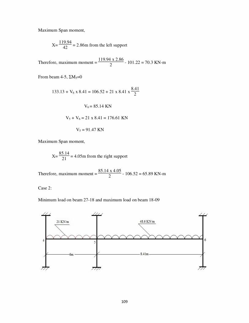
109
Maximum Span moment,
X= 119.94
42 = 2.86m from the left support
Therefore, maximum moment = 119.94 x 2.86
2 - 101.22 = 70.3 KN-m
From beam 4-5, ΣM5=0
133.13 + V6 x 8.41 = 106.52 + 21 x 8.41 x 8.41
2
V6 = 85.14 KN
V5 + V6 = 21 x 8.41 = 176.61 KN
V5 = 91.47 KN
Maximum Span moment,
X= 85.14
21 = 4.05m from the right support
Therefore, maximum moment = 85.14 x 4.05
2 - 106.52 = 65.89 KN-m
Case 2:
Minimum load on beam 27-18 and maximum load on beam 18-09
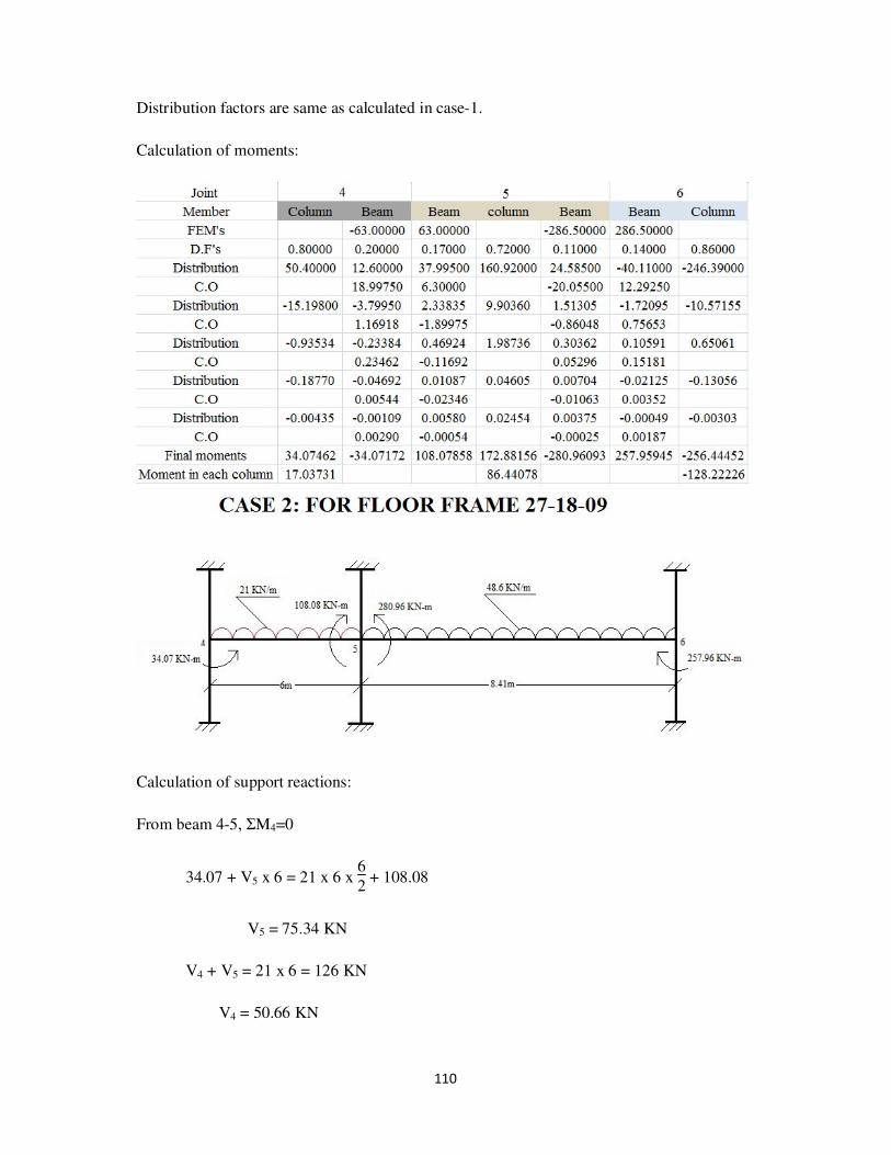
110
Distribution factors are same as calculated in case-1.
Calculation of moments:
Calculation of support reactions:
From beam 4-5, ΣM4=0
34.07 + V5 x 6 = 21 x 6 x 6
2 + 108.08
V5 = 75.34 KN
V4 + V5 = 21 x 6 = 126 KN
V4 = 50.66 KN

111
Maximum Span moment,
X= 50.66
21 = 2.41m from the left support
Therefore, maximum moment = 50.66 x 2.41
2 - 34.07 = 26.98 KN-m
From beam 4-5, ΣM5=0
280.96 + V6 x 8.41 = 257.96 + 48.6 x 8.41 x 8.41
2
V6 = 201.63 KN
V5 + V6 = 48.6 x 8.41 = 408.73 KN
V5 = 207.1 KN
Maximum Span moment,
X= 201.63
48.6 = 4.15m from the right support
Therefore, maximum moment = 201.63 x 4.15
2 - 257.96= 160.42 KN-m
Case 3:
Maximum load on both beams

112
Distribution factors are same as calculated in case 1.
Calculation of moments:
Calculation of support reactions:
From beam 4-5, ΣM4=0
89.24 + V5 x 6 = 42 x 6 x 6
2 + 166.05
V5 = 138.8 KN
V4 + V5 = 42 x 6 = 252 KN
V4 = 113.2 KN
Maximum Span moment,

113
X= 113.2
42 = 2.7m from the left support
Therefore, maximum moment = 113.2 x 2.7
2 - 89.24 = 63.58 KN-m
From beam 4-5, ΣM5=0
288.45 + V6 x 8.41 = 254.55 + 48.6 x 8.41 x 8.41
2
V6 = 200.33 KN
V5 + V6 = 48.6 x 8.41 = 408.73 KN
V5 = 208.4 KN
Maximum Span moment,
X= 200.33
48.6 = 4.12m from the right support
Therefore, maximum moment = 200.33 x 4.12
2 - 254.55= 158.33 KN-m
Beam and column bending moments (KN-m):
Joint 4 Joint 5 Joint 6
Case Column Beam Max
span
moment
Beam Column Beam Max
span
moment
Beam Column
1 50.61 101.22 70.3 137.6 2.24 133.12 65.89 106.09 53.26
2 17.04 34.07 26.98 108.08 86.44 280.96 160.42 257.96 128.22
3 44.62 89.24 63.58 166.06 61.2 288.45 158.33 254.55 126.86
Max 50.61 101.22 70.3 166.06 86.44 288.45 160.42 257.96 128.22
Shear or support reaction (KN):

114
Case no. Joint 4 Joint 5 Joint 6
1 119.94 132.06 91.47 85.14
2 50.66 75.34 207.28 201.63
3 113.2 138.8 208.4 200.33
Maximum shear 119.94 138.8 208.4 200.33
Maximum column load 119.94 347.2 200.33

115
4. DESIGN OF BEAMS
Bending moment diagram for entire building:

116
1. Longitudinal beams
a. Beam 23-24
Roof:
Section: 230mm x 300mm (b x D)
Cover: 25mm
Effective depth (d’) = 300 – 25 = 275mm
Concrete: M20 Steel: Fe415
Loads:
Slab: 110mm thick
Dead load = self weight + floor finish
= 0.11 x 25 +2.5 = 5.25 KN/m2
Live load = 1.5 KN/m2
Acting on beam:
Dead load:
Self weight = 0.23 x 25 x (0.3 – 0.11) = 1.1 KN/m
Slab = 5.25 x 3.05
6 = 2.67 KN/m
Parapet wall (250mm wall including plastering of 1m height)
= 20 x 0.25 x 1 = 5 KN/m
Live load:
Slab = 1.5 x 3.05
6 = 0.76 KN/m
Therefore, Total load (W) = 5 + 2.67 + 1.1 + 0.76 = 9.53 KN/m
Factored load (Wu) = 1.5 x 9.53 = 14.3 KN/m

117
Maximum load on column removing the triangular load = 1.5 (1.1 +5)
= 9.15 KN/m
Shear on column = column load x l
2 =
9.15 x 3.05
2 = 13.96 KN (from each side)
Design moment:
Mu = 14.3 x (3.05)2
12 = 11.09 x 10⁶ N-mm = 11.09 KN-m
Calculation of Ast:
From IS456-2000, P96a, clause G-1.1 (b), we have
Mu = 0.87 x fy x Ast x d x (1 - fy x Ast
fck x b x d )
11.09 x 106 = 0.87 x 415 x Ast x 275 x (1- 415 x Ast
20 x 230 x 275 )
Ast = 116.12 mm2
No. of 10mm diameter bars = 4 x 116.12
π x 102 = 1.5 say 2 bars
Therefore, provided Ast = 2 x π4
x 102 = 157.08 mm
2
Design of shear reinforcement:
Vu = Wu x Lx
2 =
14.3 x 3.05
2 = 21.81KN
Nominal shear stress, v = Vu
b x d =
21.81 x 10³
230 x 275 = 0.35 N/mm2
Ast = 157.08 mm2
Consider Pt = 100 xAst
b x d =
100 x 157.08
230 x 275 = 0.25

118
From IS 456-2000, Table 19:
Pt c
0.25 0.36
Therefore, c = 0.36 N/mm2
v approximately equals to c
Therefore, provide minimum shear reinforcement.
Assuming 8mmφ- 2legged stirrups
Asv = 2 x π x 8
2
4 = 100.53mm
2
Min shear reinforcement (IS456-2000, clause 26.5.1.6, P48)
Asv
b x Sv ≥
0.4
0.87 x fy
Asv = 0.4 x 230 x 300
0.87 x 415 = 76.44mm2 <100.5mm2 (safe)
Provide 8mm dia stirrups @ 300mm c/c.
Floor:
Section: 230mm x 450mm (b x D)
Cover: 25mm
Effective depth (d’) = 450 – 25 = 425mm
Concrete: M20 Steel: Fe415

119
Loads:
Slab: 120mm thick
Dead load = self weight + floor finish
= 0.12 x 25 +1 = 4 KN/m2
Live load = 10 KN/m2
Acting on beam:
Dead load:
Self weight = 0.23 x 25 x (0.45 – 0.12) = 1.9 KN/m
Slab = 4 x 3.05
6 = 2.03 KN/m
Parapet wall (250mm wall including plastering of 2.2m height)
= 20 x 0.25 x (3.35-0.3) = 15.25 KN/m
Live load:
Slab = 10 x 3.05
6 = 5.08 KN/m
Therefore, Total load (W) = 1.9 + 2.03 + 15.25 + 5.08 = 24.26 KN/m
Factored load (Wu) = 1.5 x 24.26 = 36.39 KN/m
Maximum load on column removing the triangular load = 1.5 (1.9 +5.08)
= 25.725 KN/m
Shear on column = column load x l
2 =
25.725 x 3.05
2
= 39.23 KN (from each side)
Design moment:
Mu = 36.39 x (3.05)2
12 = 28.21 x 10⁶ N-mm = 28.21 KN-m
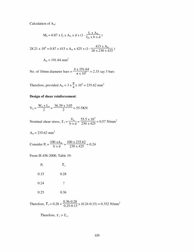
120
Calculation of Ast:
Mu = 0.87 x fy x Ast x d x (1 - fy x Ast
fck x b x d )
28.21 x 106 = 0.87 x 415 x Ast x 425 x (1- 415 x Ast
20 x 230 x 425 )
Ast = 191.64 mm2
No. of 10mm diameter bars = 4 x 191.64
π x 102 = 2.33 say 3 bars
Therefore, provided Ast = 3 x π4
x 102 = 235.62 mm
2
Design of shear reinforcement:
Vu = Wu x Lx
2 =
36.39 x 3.05
2 = 55.5KN
Nominal shear stress, v = Vu
b x d =
55.5 x 10³
230 x 425 = 0.57 N/mm2
Ast = 235.62 mm2
Consider Pt = 100 xAst
b x d =
100 x 235.62
230 x 425 = 0.24
From IS 456-2000, Table 19:
Pt c
0.15 0.28
0.24 ?
0.25 0.36
Therefore, c = 0.28 + 0.36-0.28
0.25-0.15 x (0.24-0.15) = 0.352 N/mm
2
Therefore, v > c,

121
From IS456-2000(Clause 40.4, P72)
When v exceeds c, shear reinforcement shall be provided
Shear reinforcement shall be provided to carry a shear equal to Vu - cbd. The strength of
shear reinforcement Vus shall be calculated as follows:
Vus = 0.87 x fy x Asv x d
sv
Stirrups are designed for shear Vus = Vu - cbd
= (55.5 x 10³) – (0.32 x 230 x 425)
= 24220N
Assuming 8mmφ- 2legged stirrups
Asv = 2 x π x 8
2
4 = 100.53mm
2
Therefore,
Spacing of stirrups, sv = 0.87 x fy x Asv x d
Vus =
0.87 x 415 x 100.53 x 425
24220
=636.9mm
From IS456-2000, (clause 26.5.1.5, P47)
The maximum spacing of shear reinforcement measured along the axis of the member shall
not be exceed 0.75d for vertical stirrups where d is the effective depth of the section under
consideration. In no case shall the spacing exceed 300mm.
Provide spacing = 300mm
Therefore, Vus = 0.87 x fy x Asv x d
sv =
0.87 x 415 x 100.53 x 425
300 = 51419.83N
Min shear reinforcement (IS456-2000, clause 26.5.1.6, P48)
Asv
b x Sv ≥
0.4
0.87 x fy

122
Asv = 0.4 x 230 x 300
0.87 x 415 = 76.44mm2 <100.5mm2 (safe)
Provide 8mm dia stirrups @ 300mm c/c.
b. Beam 14-15
Roof:
Section: 230mm x 300mm (b x D)
Cover: 25mm
Effective depth (d’) = 300 – 25 = 275mm
Concrete: M20 Steel: Fe415
Loads:
Slab: 110mm thick
Dead load = self weight + floor finish
= 0.11 x 25 +2.5 = 5.25 KN/m2
Live load = 1.5 KN/m2
Acting on beam:
Dead load:
Self weight = 0.23 x 25 x (0.3 – 0.11) = 1.1 KN/m
Slab = 2 x 5.25 x 3.05
6 = 5.34 KN/m

123
Live load:
Slab = 2 x 1.5 x 3.05
6 = 1.53 KN/m
Therefore, Total load (W) = 1.1 + 5.34 + 1.53 = 7.97 KN/m
Factored load (Wu) = 1.5 x 7.97 = 11.96 KN/m
Maximum load on column removing the triangular load = 1.5 (1.1)
= 1.65 KN/m
Shear on column = column load x l
2 =
1.65 x 3.05
2 = 2.52 KN (from each side)
Design moment:
Mu = 11.96 x (3.05)
2
12 = 9.27 x 10
6 N-mm = 9.27 KN-m
Calculation of Ast:
Mu = 0.87 x fy x Ast x d x (1 - fy x Ast
fck x b x d )
9.27 x 106 = 0.87 x 415 x Ast x 275 x (1-
415 x Ast
20 x 230 x 275 )
Ast = 96.41 mm2
No. of 8mm diameter bars = 4 x 96.41
π x 82 = 1.91 say 2 bars
Therefore, provided Ast = 2 x π4
x 82 = 100.53 mm2
Design of shear reinforcement:
Vu = Wu x Lx
2 =
11.96 x 3.05
2 = 18.239KN
Nominal shear stress, v = Vu
b x d =
18.239 x 10³
230 x 275 = 0.29 N/mm
2
Ast = 100.53 mm2

124
Consider Pt = 100 xAst
b x d =
100 x 100.53
230 x 275 = 0.15
From IS 456-2000, Table 19:
Pt c
0.15 0.28
Therefore, c = 0.28 N/mm2
v approximately equals to c
Therefore, provide minimum shear reinforcement.
Assuming 8mmφ- 2legged stirrups
Asv = 2 x π x 82
4 = 100.53mm2
Provide spacing = 300mm
Therefore, Vus = 0.87 x fy x Asv x d
sv =
0.87 x 415 x 100.53 x 275
300 = 33371.66KN
Min shear reinforcement (IS456-2000, clause 26.5.1.6, P48)
Asv
b x Sv ≥
0.4
0.87 x fy
Asv = 0.4 x 230 x 300
0.87 x 415 = 76.44mm
2 <100.5mm
2 (safe)
Provide 8mm dia stirrups @ 300mm c/c.

125
Floor:
Section: 230mm x 450mm (b x D)
Cover: 25mm
Effective depth (d’) = 450 – 25 = 425mm
Concrete: M20 Steel: Fe415
Loads:
Slab: 120mm thick
Dead load = self weight + floor finish + wall
= 0.12 x 25 +1 + 1.5 = 5.5 KN/m2
Live load = 10 KN/m2 + 5 KN/m2
Acting on beam:
Dead load:
Self weight = 0.23 x 25 x (0.45 – 0.12) = 1.9 KN/m
Slab = 5.5 x 3.05
6 +
4 x 3.05
6 = 4.83 KN/m
Internal wall (150mm wall including plastering of 2.2m height)
= 20 x 0.15 x 2.2 = 6.6 KN/m
Live load:
Slab = 15 x 3.05
6 = 7.625 KN/m
Therefore, Total load (W) = 1.9 + 4.83 + 6.6 + 7.625 = 20.955 KN/m
Factored load (Wu) = 1.5 x 20.955 = 31.4325 KN/m
Maximum load on column removing the triangular load = 1.5 (1.9 +6.6)
= 12.75 KN/m
126
Shear on column = column load x l
2 =
12.75 x 3.05
2
= 19.44 KN (from each side)
Design moment:
Mu = 31.4325 x (3.05)
2
12 = 24.37 x 10
6 N-mm = 24.37 KN-m
Calculation of Ast:
Mu = 0.87 x fy x Ast x d x (1 - fy x Ast
fck x b x d )
24.37 x 106 = 0.87 x 415 x Ast x 425 x (1- 415 x Ast
20 x 230 x 425 )
Ast = 164.5 mm2
No. of 10mm diameter bars = 4 x 164.5
π x 102 = 2.1 say 3 bars
Therefore, provided Ast = 3 x π4
x 102 = 235.62 mm
2
Design of shear reinforcement:
Vu = Wu x Lx
2 =
20.955 x 3.05
2 = 31.96KN
Nominal shear stress, v = Vu
b x d =
31.96 x 10³
230 x 425 = 0.33 N/mm2
Ast = 235.62 mm2
Consider Pt = 100 xAst
b x d =
100 x 235.62
230 x 425 = 0.24
From IS 456-2000, Table 19:
Pt c
0.15 0.28

127
0.24 ?
0.25 0.36
Therefore, c = 0.28 + 0.36-0.28
0.25-0.15 x (0.24-0.15) = 0.352 N/mm
2
Therefore, v approximately equals to c,
Assuming 8mmφ- 2legged stirrups
Asv = 2 x π x 82
4 = 100.53mm2
Min shear reinforcement (IS456-2000, clause 26.5.1.6, P48)
Asv
b x Sv ≥
0.4
0.87 x fy
Asv = 0.4 x 230 x 300
0.87 x 415 = 76.44mm
2 <100.5mm
2 (safe)
Provide 8mm dia stirrups @ 300mm c/c.
c. Beam 7-8
Roof:
Section: 230mm x 300mm (b x D)
Cover: 25mm
Effective depth (d’) = 300 – 25 = 275mm
Concrete: M20 Steel: Fe415

128
Loads:
Slab: 110mm thick
Dead load = self weight + floor finish
= 0.11 x 25 +2.5 = 5.25 KN/m2
Live load = 1.5 KN/m2
Acting on beam:
Dead load:
Self weight = 0.23 x 25 x (0.3 – 0.11) = 1.1 KN/m
Slab = 5.25 x 3.05
6 = 2.67 KN/m
Parapet wall (250mm wall including plastering of 1m height)
= 20 x 0.25 x 1 = 5 KN/m
Live load:
Slab = 1.5 x 3.05
6 = 0.76 KN/m
Therefore, Total load (W) = 5 + 2.67 + 1.1 + 0.76 = 9.53 KN/m
Factored load (Wu) = 1.5 x 9.53 = 14.3 KN/m
Maximum load on column removing the triangular load = 1.5 (1.1 +5)
= 9.15 KN/m
Shear on column = column load x l
2 =
9.15 x 3.05
2 = 13.96 KN (from each side)
Design moment:
Mu = 14.3 x (3.05)
2
12 = 11.09 x 10
6 N-mm = 11.09 KN-m

129
Calculation of Ast:
From IS456-2000, P96a, clause G-1.1 (b), we have
Mu = 0.87 x fy x Ast x d x (1 - fy x Ast
fck x b x d )
11.09 x 106 = 0.87 x 415 x Ast x 275 x (1-
415 x Ast
20 x 230 x 275 )
Ast = 116.12 mm2
No. of 10mm diameter bars = 4 x 116.12
π x 102 = 1.5 say 2 bars
Therefore, provided Ast = 2 x π4
x 102 = 157.08 mm2
Design of shear reinforcement:
Vu = Wu x Lx
2 =
14.3 x 3.05
2 = 21.81KN
Nominal shear stress, v = Vu
b x d =
21.81 x 10³
230 x 275 = 0.35 N/mm
2
Ast = 157.08 mm2
Consider Pt = 100 xAst
b x d =
100 x 157.08
230 x 275 = 0.25
From IS 456-2000, Table 19:
Pt c
0.25 0.36
Therefore, c = 0.36 N/mm2
v approximately equals to c
Therefore, provide minimum shear reinforcement.
Assuming 8mmφ- 2legged stirrups

130
Asv = 2 x π x 82
4 = 100.53mm2
Min shear reinforcement (IS456-2000, clause 26.5.1.6, P48)
Asv
b x Sv ≥
0.4
0.87 x fy
Asv = 0.4 x 230 x 300
0.87 x 415 = 76.44mm
2 <100.5mm
2 (safe)
Provide 8mm dia stirrups @ 300mm c/c.
Floor:
Section: 230mm x 450mm (b x D)
Cover: 25mm
Effective depth (d’) = 450 – 25 = 425mm
Concrete: M20 Steel: Fe415
Loads:
Slab: 120mm thick
Dead load = self weight + floor finish + wall
= 0.12 x 25 +1 + 1.5 = 5.5 KN/m2
Live load = 6 KN/m2
Acting on beam:
Dead load:
Self weight = 0.23 x 25 x (0.45 – 0.12) = 1.9 KN/m

131
Slab = 5.5 x 3.05
6 = 2.8 KN/m
External wall (250mm wall including plastering)
= 20 x 0.25 x (3.35 – 0.3) = 15.25 KN/m
Live load:
Slab = 6 x 3.05
6 = 3.05 KN/m
Therefore, Total load (W) = 1.9 + 2.8 + 15.25 + 3.05 = 23 KN/m
Factored load (Wu) = 1.5 x 23 = 34.5 KN/m
Maximum load on column removing the triangular load = 1.5 (1.9 +15.25)
= 25.73 KN/m
Shear on column = column load x l
2 =
25.73 x 3.05
2
= 39.24 KN (from each side)
Design moment:
Mu = 34.5 x (3.05)
2
12 = 26.75 x 10
6 N-mm = 26.75 KN-m
Calculation of Ast:
Mu = 0.87 x fy x Ast x d x (1 - fy x Ast
fck x b x d )
26.75 x 106 = 0.87 x 415 x Ast x 425 x (1- 415 x Ast
20 x 230 x 425 )
Ast = 181.3 mm2
No. of 10mm diameter bars = 4 x 181.3
π x 102 = 2.31 say 3 bars
Therefore, provided Ast = 3 x π4
x 102 = 235.62 mm
2

132
Design of shear reinforcement:
Vu = Wu x Lx
2 =
34.5 x 3.05
2 = 52.61KN
Nominal shear stress, v = Vu
b x d =
52.61 x 10³
230 x 425 = 0.54 N/mm2
Ast = 235.62 mm2
Consider Pt = 100 xAst
b x d =
100 x 235.62
230 x 425 = 0.24
From IS 456-2000, Table 19:
Pt c
0.15 0.28
0.24 ?
0.25 0.36
Therefore, c = 0.28 + 0.36-0.28
0.25-0.15 x (0.24-0.15) = 0.352 N/mm
2
Therefore, v > c,
Stirrups are designed for shear Vus = Vu - cbd
= (52.61 x 10³) – (0.35 x 230 x 425)
= 18397.5N
Assuming 8mmφ- 2legged stirrups
Asv = 2 x π x 8
2
4 = 100.53mm
2
Therefore,
Spacing of stirrups, sv = 0.87 x fy x Asv x d
Vus =
0.87 x 415 x 100.53 x 425
18397.5
= 838.48mm

133
Provide spacing = 300mm
Therefore, Vus = 0.87 x fy x Asv x d
sv =
0.87 x 415 x 100.53 x 425
300 = 51419.83N
Min shear reinforcement (IS456-2000, clause 26.5.1.6, P48)
Asv
b x Sv ≥
0.4
0.87 x fy
Asv = 0.4 x 230 x 300
0.87 x 415 = 76.44mm2 <100.5mm2 (safe)
Provide 8mm dia stirrups @ 300mm c/c.

134
2. Transverse beams:
a. Beam 19-10 and Beam 10-01

135
ROOF: (section 230mm x 300mm, d' = 25mm)
From analysis of frames the moments acting on the supports are:
At left support (Ast1):
Moment due to external load (Mu) = 64.65 KN-m
From IS456-2000, P96, clause G-1.1 (c), moment of resistance of the section is given by
Mu’Limit = 0.36 x xumax
d x (1- 0.42 x
xumax
d ) x b x d2 x fck
For Fe 415, xumax
d = 0.48
Mu’limit = 0.138 x fck x b x d2
= 0.138 x 20 x 230 x (275)2 = 48 x 10
6 N-mm = 48 KN-m
Mu > Mu’limit , therefore design as doubly reinforced beam.
Consider d'
d =
25
275 = 0.1
Therefore, fsc = 353 N/mm2
Area of steel in compression (Asc):
Asc = Mu - Mu’limit
fsc x (d - d') =
(64.65 - 48) x 106
353 x (275 - 25) =188.67 mm
2
To find Ast1:
Mu’limit = 0.87 x fy x Ast1 x d x (1 - fy x Ast1
fck x b x d )

136
48 x 106 = 0.87 x 415 x Ast1 x 275 x (1 - 415 x Ast1
20 x 230 x 275 )
Ast1 = 602.55 mm2
To find Ast2:
Ast2 = fsc x Asc
0.87 x fy =
353 x 188.67
0.87 x 415 =184.46 mm
2
Ast = Ast1 + Ast2 = 602.55 + 184.46 = 787.01 mm2
Between the support:
Span moment = 39.24 KN-m
For T-beam, from IS456-2000, P37, clause 23.1.2 (a)
Effective width of flange (bf) = l06
+ (6 x Df) + bw
l0 = 0.7 x l = 0.7 x 6000 = 4200 mm
Therefore, bf = 4200
6 + (6 x 110) + 230
= 1590 mm
Therefore Mu’limit = 0.36 x fck x bf x Df x(d – 0.42Df)
= 0.36 x 20 x 1590 x 110 x (275 – 0.42 x 110)
= 288.12 KN-m
Mu < < Mu’limit
Ast:
39.24 x 106 = 0.87 x 415 x Ast2 x 275 x (1-
415 x Ast2
20 x 230 x 275 )
Ast2 = 466.65 mm2

137
At right support (Ast3):
Moment due to external load (Mu) = 86.09 KN-m
Mu’limit = 0.138 x fck x b x d2
= 0.138 x 20 x 230 x (275)2 = 48 x 106 N-mm = 48 KN-m
Mu > Mu’limit , therefore design as doubly reinforced beam.
Consider d'
d =
25
275 = 0.1
Therefore, fsc = 353 N/mm2
Area of steel in compression (Asc):
Asc = Mu - Mu’limit
fsc x (d - d') =
(86.09 - 48) x 106
353 x (275 - 25) =431.62 mm2
To find Ast1:
Mu’limit = 0.87 x fy x Ast1 x d x (1 - fy x Ast1
fck x b x d )
48 x 106 = 0.87 x 415 x Ast1 x 275 x (1 -
415 x Ast1
20 x 230 x 275 )
Ast1 = 602.55 mm2
To find Ast2:
Ast2 = fsc x Asc
0.87 x fy =
353 x 431.62
0.87 x 415 =422 mm2
Ast3 = Ast1 + Ast2 = 602.55 + 422 = 1024.55 mm2
At support (Ast4):
Moment due to external load (Mu) = 145.76 KN-m
Mu’limit = 0.138 x fck x b x d2
= 0.138 x 20 x 230 x (275)2 = 48 x 10
6 N-mm = 48 KN-m

138
Mu > Mu’limit , therefore design as doubly reinforced beam.
Consider d'
d =
25
275 = 0.1
Therefore, fsc = 353 N/mm2
Area of steel in compression (Asc):
Asc = Mu - Mu’limit
fsc x (d - d') =
(145.76 - 48) x 106
353 x (275 - 25) =1107.76 mm
2
To find Ast1:
Mu’limit = 0.87 x fy x Ast1 x d x (1 - fy x Ast1
fck x b x d )
48 x 106 = 0.87 x 415 x Ast1 x 275 x (1 -
415 x Ast1
20 x 230 x 275 )
Ast1 = 602.55 mm2
To find Ast2:
Ast2 = fsc x Asc
0.87 x fy =
353 x 1107.76
0.87 x 415 =1083.06 mm
2
Ast4 = Ast1 + Ast2 = 602.55 + 1083 = 1685.61 mm2
Between the support (Ast5):
Span moment = 77.97 KN-m
Effective width of flange (bf) = l06
+ (6 x Df) + bw
l0 = 0.7 x l = 0.7 x 8410 = 5887 mm
Therefore, bf = 5887
6 + (6 x 110) + 230
= 1871.16 mm

139
Therefore Mu’limit = 0.36 x fck x bf x Df x(d – 0.42Df)
= 0.36 x 20 x 1871.16 x 110 x (275 – 0.42 x 110)
= 339.07 KN-m
Mu < Mu’limit
Ast:
77.97 x 106 = 0.87 x 415 x Ast5 x 275 x (1-
415 x Ast5
20 x 230 x 275 )
Ast5 = 1411.66 mm2
At right end (Ast6):
Moment due to external load (Mu) = 136.01 KN-m
Mu’limit = 0.138 x fck x b x d2
= 0.138 x 20 x 230 x (275)2 = 48 x 10
6 N-mm = 48 KN-m
Mu > Mu’limit , therefore design as doubly reinforced beam.
Consider d'
d =
25
275 = 0.1
Therefore, fsc = 353 N/mm2
Area of steel in compression (Asc):
Asc = Mu - Mu’limit
fsc x (d - d') =
(136.01 - 48) x 106
353 x (275 - 25) =997.28 mm
2
To find Ast1:
Mu’limit = 0.87 x fy x Ast1 x d x (1 - fy x Ast1
fck x b x d )
48 x 106 = 0.87 x 415 x Ast1 x 275 x (1 - 415 x Ast1
20 x 230 x 275 )
Ast1 = 602.55 mm2
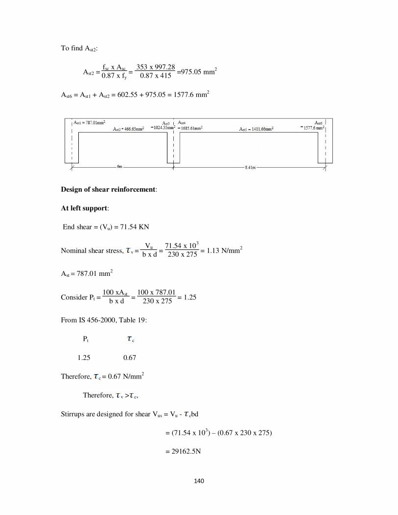
140
To find Ast2:
Ast2 = fsc x Asc
0.87 x fy =
353 x 997.28
0.87 x 415 =975.05 mm
2
Ast6 = Ast1 + Ast2 = 602.55 + 975.05 = 1577.6 mm2
Design of shear reinforcement:
At left support:
End shear = (Vu) = 71.54 KN
Nominal shear stress, v = Vu
b x d =
71.54 x 10³
230 x 275 = 1.13 N/mm
2
Ast = 787.01 mm2
Consider Pt = 100 xAst
b x d =
100 x 787.01
230 x 275 = 1.25
From IS 456-2000, Table 19:
Pt c
1.25 0.67
Therefore, c = 0.67 N/mm2
Therefore, v > c,
Stirrups are designed for shear Vus = Vu - cbd
= (71.54 x 10³) – (0.67 x 230 x 275)
= 29162.5N
141
Assuming 8mmφ- 2legged stirrups
Asv = 2 x π x 8
2
4 = 100.53mm
2
Therefore,
Spacing of stirrups, sv = 0.87 x fy x Asv x d
Vus =
0.87 x 415 x 100.53 x 275
29162.5
= 342.27mm
Provide spacing = 300mm
Therefore, Vus = 0.87 x fy x Asv x d
sv =
0.87 x 415 x 100.53 x 275
300 = 33261.73N
Min shear reinforcement (IS456-2000, clause 26.5.1.6, P48)
Asv
b x Sv ≥
0.4
0.87 x fy
Asv = 0.4 x 230 x 300
0.87 x 415 = 76.44mm2 <100.5mm2 (safe)
Therefore, provide 8mm dia stirrups @ 300mm c/c.
At middle support:
End shear = (Vu) = 77.92 KN
Nominal shear stress, v = Vu
b x d =
77.92 x 10³
230 x 275 = 1.23 N/mm
2
Ast = 1024.55 mm2
Consider Pt = 100 xAst
b x d =
100 x 1024.55
230 x 275 = 1.62
From IS 456-2000, Table 19:
Pt c
1.5 0.72

142
1.62 ?
1.75 0.75
Therefore, c = 0.72 + 0.75-0.72
1.75-1.5 x (1.62-1.5) = 0.734 N/mm
2
Therefore, v > c,
Stirrups are designed for shear Vus = Vu - cbd
= (77.92 x 10³) – (0.734 x 230 x 275)
= 31494.5N
Assuming 8mmφ- 2legged stirrups
Asv = 2 x π x 82
4 = 100.53mm2
Therefore,
Spacing of stirrups, sv = 0.87 x fy x Asv x d
Vus =
0.87 x 415 x 100.53 x 275
31494.5
= 316.93mm
Provide spacing = 300mm
Therefore, Vus = 0.87 x fy x Asv x d
sv =
0.87 x 415 x 100.53 x 275
300 = 33261.73N
Min shear reinforcement (IS456-2000, clause 26.5.1.6, P48)
Asv
b x Sv ≥
0.4
0.87 x fy
Asv = 0.4 x 230 x 300
0.87 x 415 = 76.44mm
2 <100.5mm
2 (safe)
Therefore, provide 8mm dia stirrups @ 300mm c/c.

143
At middle support:
End shear = (Vu) = 104.84 KN
Nominal shear stress, v = Vu
b x d =
104.84 x 10³
230 x 275 = 1.66 N/mm
2
Ast = 1685.61 mm2
Consider Pt = 100 xAst
b x d =
100 x 1685.61
230 x 275 = 2.67
From IS 456-2000, Table 19:
Pt c
2.67 0.82
Therefore, c = 0.82 N/mm2
Therefore, v > c,
Stirrups are designed for shear Vus = Vu - cbd
= (104.84 x 10³) – (0.82 x 230 x 275)
= 52975N
Assuming 8mmφ- 2legged stirrups
Asv = 2 x π x 82
4 = 100.53mm
2
Therefore,
Spacing of stirrups, sv = 0.87 x fy x Asv x d
Vus =
0.87 x 415 x 100.53 x 275
52975
= 188.42mm < 300mm
Min shear reinforcement (IS456-2000, clause 26.5.1.6, P48)
Asv
b x Sv ≥
0.4
0.87 x fy

144
Asv = 0.4 x 230 x 180
0.87 x 415 = 45.87mm2 <100.5mm2 (safe)
Therefore, provide 8mm dia stirrups @ 180mm c/c.
At right support:
End shear = (Vu) = 102.63 KN
Nominal shear stress, v = Vu
b x d =
102.63 x 10³
230 x 275 = 1.63 N/mm
2
Ast = 1577.6 mm2
Consider Pt = 100 xAst
b x d =
100 x 1577.6
230 x 275 = 2.5
From IS 456-2000, Table 19:
Pt c
2.5 0.82
Therefore, c = 0.82 N/mm2
Therefore, v > c,
Stirrups are designed for shear Vus = Vu - cbd
= (102.63 x 10³) – (0.82 x 230 x 275)
= 50765N
Assuming 8mmφ- 2legged stirrups
Asv = 2 x π x 82
4 = 100.53mm2
Therefore,
Spacing of stirrups, sv = 0.87 x fy x Asv x d
Vus =
0.87 x 415 x 100.53 x 275
50765
= 196.62mm < 300mm

145
Min shear reinforcement (IS456-2000, clause 26.5.1.6, P48)
Asv
b x Sv ≥
0.4
0.87 x fy
Asv = 0.4 x 230 x 190
0.87 x 415 = 48.41mm2 <100.5mm2 (safe)
Therefore, provide 8mm dia stirrups @ 190mm c/c.
Reinforcement for roof 19-10-01:
FLOOR: (section: 230mm x 450mm, d’= 25mm)
The moments acting on the beam are:
At left support (Ast1):
Moment due to external load (Mu) = 106.54 KN-m
Mu’limit = 0.138 x fck x b x d2
= 0.138 x 20 x 230 x (425)2 = 114.66 x 10⁶ N-mm = 114.66 KN-m
Mu < Mu’limit , therefore design as singly reinforced beam.

146
To find Ast1:
Mu’limit = 0.87 x fy x Ast1 x d x (1 - fy x Ast1
fck x b x d )
106.54 x 106 = 0.87 x 415 x Ast1 x 425 x (1 - 415 x Ast1
20 x 230 x 425 )
Ast1 = 546 mm2
Between the supports (Ast2):
Span moment = 73.58 KN-m
Effective width of flange (bf) = l06
+ (6 x Df) + bw
l0 = 0.7 x l = 0.7 x 6000 = 4200 mm
Therefore, bf = 4200
6 + (6 x 120) + 230
= 1650 mm
Therefore Mu’limit = 0.36 x fck x bf x Df x (d – 0.42Df)
= 0.36 x 20 x 1650 x 120 x (425 – 0.42 x 120)
= 534.03 KN-m
Mu < Mu’limit
Ast:
73.58 x 106 = 0.87 x 415 x Ast2 x 425 x (1- 415 x Ast2
20 x 230 x 425 )
Ast2 = 852.07 mm2
At right support (Ast3):
Moment due to external load (Mu) = 169.53 KN-m

147
Mu’limit = 0.138 x fck x b x d2
= 0.138 x 20 x 230 x (425)2 = 114.66 x 10
6 N-mm = 114.66 KN-m
Mu > Mu’limit , therefore design as doubly reinforced beam.
Consider d'
d =
25
425 = 0.05
Therefore, fsc = 355 N/mm2
Area of steel in compression (Asc):
Asc = Mu - Mu’limit
fsc x (d - d') =
(169.53 - 114.66) x 106
353 x (425 - 25) =386.84 mm
2
To find Ast1:
Mu’limit = 0.87 x fy x Ast1 x d x (1 - fy x Ast1
fck x b x d )
114.66 x 106 = 0.87 x 415 x Ast1 x 425 x (1 - 415 x Ast1
20 x 230 x 425 )
Ast1 = 932 mm2
To find Ast2:
Ast2 = fsc x Asc
0.87 x fy =
353 x 386.84
0.87 x 415 = 380.36 mm2
Ast3 = Ast1 + Ast2 = 932 + 380.6 = 1312.36 mm2
At support (Ast4):
Moment due to external load (Mu) = 277.32 KN-m
Mu’limit = 0.138 x fck x b x d2
= 0.138 x 20 x 230 x (425)2 = 114.66 x 10⁶ N-mm = 114.66 KN-m
Mu > Mu’limit , therefore design as doubly reinforced beam.
Consider d'
d =
25
425 = 0.05

148
Therefore, fsc = 355 N/mm2
Area of steel in compression (Asc):
Asc = Mu - Mu’limit
fsc x (d - d') =
(277.32 -11 4.66) x 106
353 x (425 - 25) =1145.5 mm
2
To find Ast1:
Mu’limit = 0.87 x fy x Ast1 x d x (1 - fy x Ast1
fck x b x d )
114.66 x 106 = 0.87 x 415 x Ast1 x 425 x (1 -
415 x Ast1
20 x 230 x 425 )
Ast1 = 932 mm2
To find Ast2:
Ast2 = fsc x Asc
0.87 x fy =
355 x 1145.5
0.87 x 415 =1126.31 mm
2
Ast4 = Ast1 + Ast2 = 923 + 1126.31 = 2058.31 mm2
Between the supports (Ast5):
Span moment = 153.57 KN-m
Effective width of flange (bf) = l06
+ (6 x Df) + bw
l0 = 0.7 x l = 0.7 x 8410 = 5887 mm
Therefore, bf = 5887
6 + (6 x 120) + 230
= 1931.67 mm
Therefore Mu’limit = 0.36 x fck x bf x Df x (d – 0.42Df)
= 0.36 x 20 x 1871.16 x 120 x (425 – 0.42 x 120)
= 625.2 KN-m
Mu < Mu’limit

149
Ast:
153.57 x 106 = 0.87 x 415 x Ast5 x 425 x (1-
415 x Ast5
20 x 230 x 425 )
Ast5 = 1442.53 mm2
At right end (Ast6):
Moment due to external load (Mu) = 246.62 KN-m
Mu’limit = 0.138 x fck x b x d2
= 0.138 x 20 x 230 x (425)2 = 114.66 x 10
6 N-mm = 114.66 KN-m
Mu > Mu’limit , therefore design as doubly reinforced beam.
Consider d'
d =
25
425 = 0.05
Therefore, fsc = 355 N/mm2
Area of steel in compression (Asc):
Asc = Mu - Mu’limit
fsc x (d - d') =
(246.62 - 114.66) x 106
355 x (425 - 25) =929.29 mm
2
To find Ast1:
Mu’limit = 0.87 x fy x Ast1 x d x (1 - fy x Ast1
fck x b x d )
114.66 x 106 = 0.87 x 415 x Ast1 x 425 x (1 - 415 x Ast1
20 x 230 x 425 )
Ast1 = 932 mm2
To find Ast2:
Ast2 = fsc x Asc
0.87 x fy =
355 x 929.29
0.87 x 415 =913.72 mm2
Ast6 = Ast1 + Ast2 = 932 + 913.72 = 1845.72 mm2
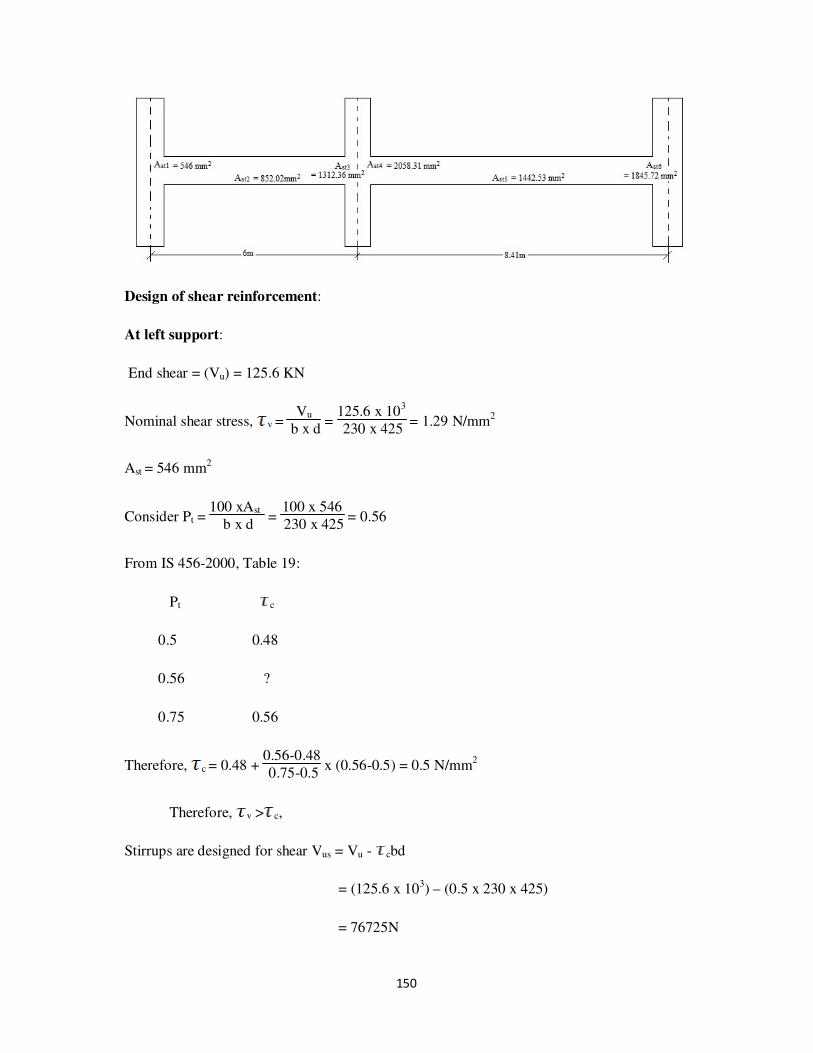
150
Design of shear reinforcement:
At left support:
End shear = (Vu) = 125.6 KN
Nominal shear stress, v = Vu
b x d =
125.6 x 10³
230 x 425 = 1.29 N/mm
2
Ast = 546 mm2
Consider Pt = 100 xAst
b x d =
100 x 546
230 x 425 = 0.56
From IS 456-2000, Table 19:
Pt c
0.5 0.48
0.56 ?
0.75 0.56
Therefore, c = 0.48 + 0.56-0.48
0.75-0.5 x (0.56-0.5) = 0.5 N/mm
2
Therefore, v > c,
Stirrups are designed for shear Vus = Vu - cbd
= (125.6 x 10³) – (0.5 x 230 x 425)
= 76725N

151
Assuming 8mmφ- 2legged stirrups
Asv = 2 x π x 8
2
4 = 100.53mm
2
Therefore,
Spacing of stirrups, sv = 0.87 x fy x Asv x d
Vus =
0.87 x 415 x 100.53 x 425
76725
= 184.87mm <300mm
Min shear reinforcement (IS456-2000, clause 26.5.1.6, P48)
Asv
b x Sv ≥
0.4
0.87 x fy
Asv = 0.4 x 230 x 180
0.87 x 415 = 45.86mm
2 <100.5mm
2 (safe)
Therefore, provide 8mm dia stirrups @ 180mm c/c.
At middle support:
End shear = (Vu) = 144.35 KN
Nominal shear stress, v = Vu
b x d =
144.35 x 10³
230 x 425 = 1.48 N/mm
2
Ast = 1312.16 mm2
Consider Pt = 100 xAst
b x d =
100 x 1312.16
230 x 425 = 1.34
From IS 456-2000, Table 19:
Pt c
1.25 0.67
1.34 ?
1.5 0.72
152
Therefore, c = 0.67 + 0.72-0.67
1.5-1.25 x (1.34-1.25) = 0.69 N/mm2
Therefore, v > c,
Stirrups are designed for shear Vus = Vu - cbd
= (144.32 x 10³) – (0.69 x 230 x 425)
= 78827.5N
Assuming 8mmφ- 2legged stirrups
Asv = 2 x π x 8
2
4 = 100.53mm
2
Therefore,
Spacing of stirrups, sv = 0.87 x fy x Asv x d
Vus =
0.87 x 415 x 100.53 x 425
78827.5
= 195.7mm
Min shear reinforcement (IS456-2000, clause 26.5.1.6, P48)
Asv
b x Sv ≥
0.4
0.87 x fy
Asv = 0.4 x 230 x 190
0.87 x 415 = 48.41mm2 <100.5mm2 (safe)
Therefore, provide 8mm dia stirrups @ 190mm c/c.
At middle support:
End shear = (Vu) = 199.64 KN
Nominal shear stress, v = Vu
b x d =
199.64 x 10³
230 x 425 = 2.04 N/mm
2
Ast = 2058.31 mm2
Consider Pt = 100 xAst
b x d =
100 x 2058.31
230 x 425 = 2

153
From IS 456-2000, Table 19:
Pt c
2.00 0.79
Therefore, c = 0.79 N/mm2
Therefore, v > c,
Stirrups are designed for shear Vus = Vu - cbd
= (199.64 x 10³) – (0.79 x 230 x 425)
= 122417.5N
Assuming 10mmφ- 2legged stirrups
Asv = 2 x π x 102
4 = 157.07mm2
Therefore,
Spacing of stirrups, sv = 0.87 x fy x Asv x d
Vus =
0.87 x 415 x 157.07 x 425
122417.5
= 196.9mm < 300mm
Min shear reinforcement (IS456-2000, clause 26.5.1.6, P48)
Asv
b x Sv ≥
0.4
0.87 x fy
Asv = 0.4 x 230 x 190
0.87 x 415 = 48.41mm
2 <157.07mm
2 (safe)
Therefore, provide 10mm dia stirrups @ 190mm c/c.
At right support:
End shear = (Vu) = 192.85 KN
Nominal shear stress, v = Vu
b x d =
192.85 x 10³
230 x 425 = 1.97 N/mm
2
154
Ast = 1845.72 mm2
Consider Pt = 100 xAst
b x d =
100 x1845.72
230 x 425 = 1.89
From IS 456-2000, Table 19:
Pt c
1.75 0.75
1.89 ?
2 0.79
Therefore, c = 0.75 + 0.79-0.75
2-1.75 x (1.89-1.75) = 0.77 N/mm
2
Therefore, v > c,
Stirrups are designed for shear Vus = Vu - cbd
= (192.85 x 10³) – (0.77 x 230 x 425)
= 117582.5N
Assuming 10mmφ- 2legged stirrups
Asv = 2 x π x 102
4 = 157.07mm2
Therefore,
Spacing of stirrups, sv = 0.87 x fy x Asv x d
Vus =
0.87 x 415 x 157.07 x 425
117582.5
= 204.98mm < 300mm
Min shear reinforcement (IS456-2000, clause 26.5.1.6, P48)
Asv
b x Sv ≥
0.4
0.87 x fy
Asv = 0.4 x 230 x 200
0.87 x 415 = 50.96mm
2 <157.07mm
2 (safe)
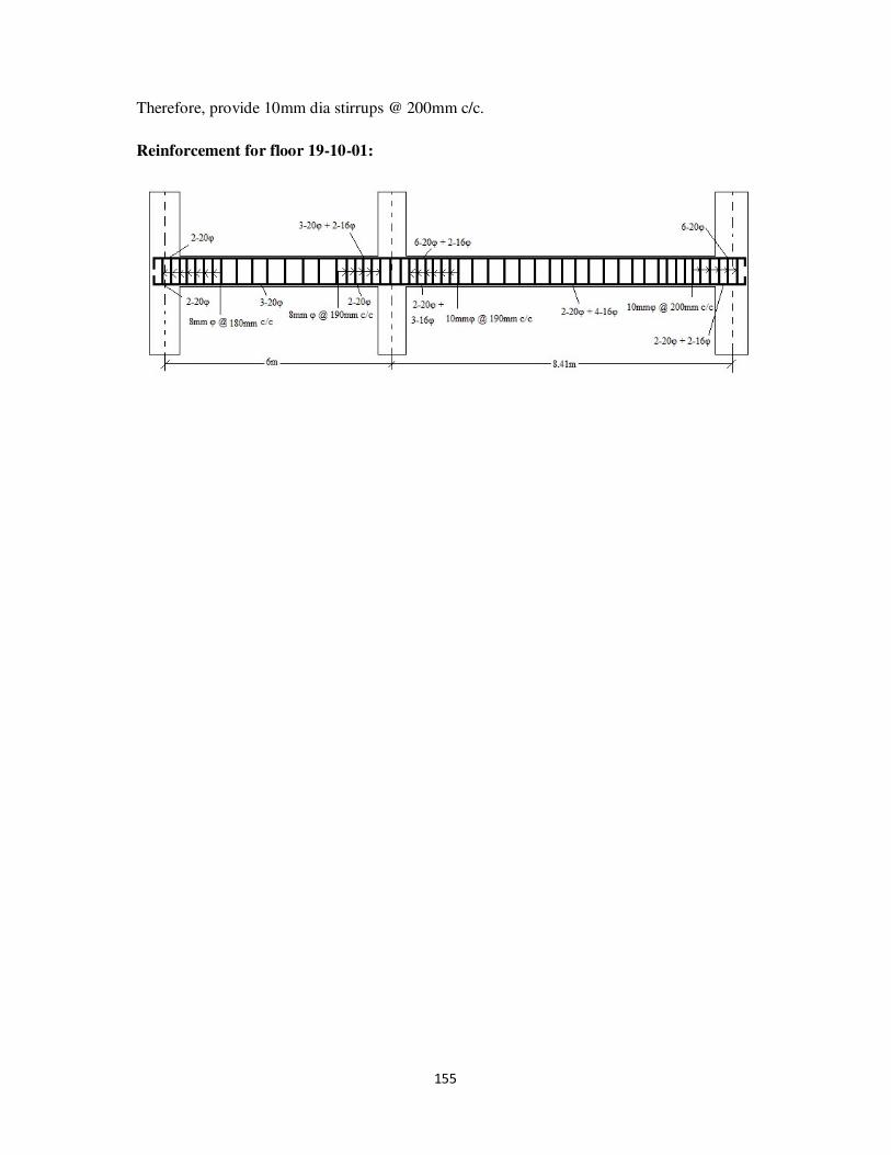
155
Therefore, provide 10mm dia stirrups @ 200mm c/c.
Reinforcement for floor 19-10-01:

156
b. Beam 20-11 and Beam 11-02

157
ROOF (section: 230mm x 450mm, d’ = 25mm)
The moments acting on the beam are:
At left support (Ast1):
Moment due to external load (Mu) = 68.42 KN-m
Mu’limit = 0.138 x fck x b x d2
= 0.138 x 20 x 230 x (425)2 = 114.66 x 10⁶ N-mm = 114.66 KN-m
Mu < Mu’limit , therefore design as singly reinforced beam.
To find Ast1:
Mu’limit = 0.87 x fy x Ast1 x d x (1 - fy x Ast1
fck x b x d )
68.42 x 106 = 0.87 x 415 x Ast1 x 425 x (1 -
415 x Ast1
20 x 230 x 425 )
Ast1 = 498.67 mm2
Between the supports (Ast2):
Span moment = 59.13 KN-m
Effective width of flange (bf) = l06
+ (6 x Df) + bw
l0 = 0.7 x l = 0.7 x 6000 = 4200 mm
Therefore, bf = 4200
6 + (6 x 110) + 230 = 1590 mm

158
Therefore Mu’limit = 0.36 x fck x bf x Df x (d – 0.42Df)
= 0.36 x 20 x 1590 x 110 x (425 – 0.42 x 110)
= 477.02 KN-m
Mu < Mu’limit
Ast:
59.13 x 106 = 0.87 x 415 x Ast2 x 425 x (1-
415 x Ast2
20 x 230 x 425 )
Ast2 = 423.4 mm2
At right support (Ast3):
Moment due to external load (Mu) = 140.51 KN-m
Mu’limit = 0.138 x fck x b x d2
= 0.138 x 20 x 230 x (425)2 = 114.66 x 10
6 N-mm = 114.66 KN-m
Mu > Mu’limit , therefore design as doubly reinforced beam.
Consider d'
d =
25
425 = 0.05
Therefore, fsc = 355 N/mm2
Area of steel in compression (Asc):
Asc = Mu - Mu’limit
fsc x (d - d') =
(140.51 - 114.66) x 106
353 x (425 - 25) =181.97 mm2
To find Ast1:
Mu’limit = 0.87 x fy x Ast1 x d x (1 - fy x Ast1
fck x b x d )
114.66 x 106 = 0.87 x 415 x Ast1 x 425 x (1 -
415 x Ast1
20 x 230 x 425 )
Ast1 = 932 mm2

159
To find Ast2:
Ast2 = fsc x Asc
0.87 x fy =
355 x 181.97
0.87 x 415 = 178.92 mm
2
Ast3 = Ast1 + Ast2 = 932 + 178.92 = 1110.4 mm2
At support (Ast4):
Moment due to external load (Mu) = 199.51 KN-m
Mu’limit = 0.138 x fck x b x d2
= 0.138 x 20 x 230 x (425)2 = 114.66 x 10
6 N-mm = 114.66 KN-m
Mu > Mu’limit , therefore design as doubly reinforced beam.
Consider d'
d =
25
425 = 0.05
Therefore, fsc = 355 N/mm2
Area of steel in compression (Asc):
Asc = Mu - Mu’limit
fsc x (d - d') =
(199.51 -11 4.66) x 106
353 x (425 - 25) =597.46 mm
2
To find Ast1:
Mu’limit = 0.87 x fy x Ast1 x d x (1 - fy x Ast1
fck x b x d )
114.66 x 106 = 0.87 x 415 x Ast1 x 425 x (1 - 415 x Ast1
20 x 230 x 425 )
Ast1 = 932 mm2
To find Ast2:
Ast2 = fsc x Asc
0.87 x fy =
355 x 597.46
0.87 x 415 =587.45 mm2
Ast4 = Ast1 + Ast2 = 923 + 587.45 = 1518.93 mm2

160
Between the supports (Ast5):
Span moment = 118.5 KN-m
Effective width of flange (bf) = l06
+ (6 x Df) + bw
l0 = 0.7 x l = 0.7 x 8410 = 5887 mm
Therefore, bf = 5887
6 + (6 x 110) + 230
= 1871.17 mm
Therefore Mu’limit = 0.36 x fck x bf x Df x (d – 0.42Df)
= 0.36 x 20 x 1871.16 x 110 x (425 – 0.42 x 110)
= 561.37 KN-m
Mu < Mu’limit
Ast:
118.5 x 106 = 0.87 x 415 x Ast5 x 425 x (1-
415 x Ast5
20 x 230 x 425 )
Ast5 = 973.38 mm2
At right end (Ast6):
Moment due to external load (Mu) = 158.81 KN-m
Mu’limit = 0.138 x fck x b x d2
= 0.138 x 20 x 230 x (425)2 = 114.66 x 10⁶ N-mm = 114.66 KN-m
Mu > Mu’limit , therefore design as doubly reinforced beam.
Consider d'
d =
25
425 = 0.05
Therefore, fsc = 355 N/mm2
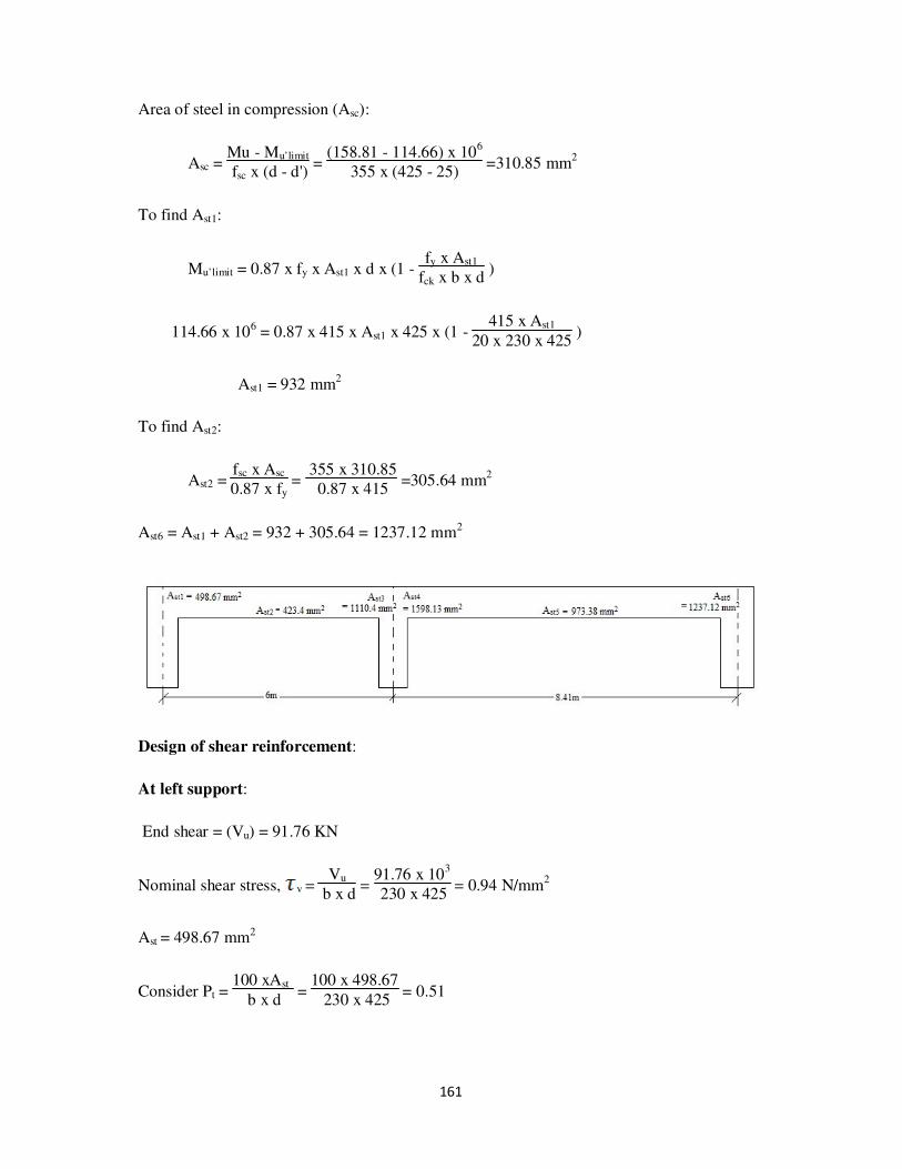
161
Area of steel in compression (Asc):
Asc = Mu - Mu’limit
fsc x (d - d') =
(158.81 - 114.66) x 106
355 x (425 - 25) =310.85 mm
2
To find Ast1:
Mu’limit = 0.87 x fy x Ast1 x d x (1 - fy x Ast1
fck x b x d )
114.66 x 106 = 0.87 x 415 x Ast1 x 425 x (1 - 415 x Ast1
20 x 230 x 425 )
Ast1 = 932 mm2
To find Ast2:
Ast2 = fsc x Asc
0.87 x fy =
355 x 310.85
0.87 x 415 =305.64 mm
2
Ast6 = Ast1 + Ast2 = 932 + 305.64 = 1237.12 mm2
Design of shear reinforcement:
At left support:
End shear = (Vu) = 91.76 KN
Nominal shear stress, v = Vu
b x d =
91.76 x 10³
230 x 425 = 0.94 N/mm
2
Ast = 498.67 mm2
Consider Pt = 100 xAst
b x d =
100 x 498.67
230 x 425 = 0.51

162
From IS 456-2000, Table 19:
Pt c
0.5 0.48
0.51 ?
0.75 0.56
Therefore, c = 0.48 + 0.56-0.48
0.75-0.5 x (0.51-0.5) = 0.483 N/mm
2
Therefore, v > c,
Stirrups are designed for shear Vus = Vu - cbd
= (91.76 x 10³) – (0.483 x 230 x 425)
= 44546.75N
Assuming 8mmφ- 2legged stirrups
Asv = 2 x π x 82
4 = 100.53mm2
Therefore,
Spacing of stirrups, sv = 0.87 x fy x Asv x d
Vus =
0.87 x 415 x 100.53 x 425
44546.75
= 346.29mm >300mm
Provide spacing = 300mm
Vus = 0.87 x fy x Asv x d
sv =
0.87 x 415 x 100.53 x 425
300 = 51419.84N
Min shear reinforcement (IS456-2000, clause 26.5.1.6, P48)
Asv
b x Sv ≥
0.4
0.87 x fy
Asv = 0.4 x 230 x 300
0.87 x 415 = 76.44mm
2 <100.5mm
2 (safe)

163
Therefore, provide 8mm dia stirrups @ 300mm c/c.
At middle support:
End shear = (Vu) = 112.78 KN
Nominal shear stress, v = Vu
b x d =
112.78 x 10³
230 x 425 = 1.15 N/mm2
Ast = 1110.4 mm2
Consider Pt = 100 xAst
b x d =
100 x 1110.4
230 x 425 = 1.14
From IS 456-2000, Table 19:
Pt c
1.00 0.62
1.15 ?
1.25 0.67
Therefore, c = 0.62 + 0.67-0.62
1.25-1 x (1.15-1.00) = 0.65 N/mm
2
Therefore, v > c,
Stirrups are designed for shear Vus = Vu - cbd
= (112.78 x 10³) – (0.65 x 230 x 425)
= 49242.5N
Assuming 8mmφ- 2legged stirrups
Asv = 2 x π x 8
2
4 = 100.53mm
2

164
Therefore,
Spacing of stirrups, sv = 0.87 x fy x Asv x d
Vus =
0.87 x 415 x 100.53 x 425
49242.5
= 313.26mm < 300mm
Provide spacing = 300mm
Vus = 0.87 x fy x Asv x d
sv =
0.87 x 415 x 100.53 x 425
300 = 51419.84N
Min shear reinforcement (IS456-2000, clause 26.5.1.6, P48)
Asv
b x Sv ≥
0.4
0.87 x fy
Asv = 0.4 x 230 x 300
0.87 x 415 = 76.44mm
2 <100.5mm
2 (safe)
Therefore, provide 8mm dia stirrups @ 300mm c/c.
At middle support:
End shear = (Vu) = 144.11 KN
Nominal shear stress, v = Vu
b x d =
144.11 x 10³
230 x 425 = 1.47 N/mm
2
Ast = 1598.13 mm2
Consider Pt = 100 xAst
b x d =
100 x 1598.13
230 x 425 = 1.64
From IS 456-2000, Table 19:
Pt c
1.50 0.72
1.64 ?
1.75 0.75
165
Therefore, c = 0.72 + 0.75-0.72
1.75-1.5 x (1.64 – 1.5) = 0.74 N/mm2
Therefore, v > c,
Stirrups are designed for shear Vus = Vu - cbd
= (144.11 x 10³) – (0.74 x 230 x 425)
= 71775N
Assuming 8mmφ- 2legged stirrups
Asv = 2 x π x 8
2
4 = 100.53mm
2
Therefore,
Spacing of stirrups, sv = 0.87 x fy x Asv x d
Vus =
0.87 x 415 x 100.53 x 425
71775
= 214.92mm < 300mm
Min shear reinforcement (IS456-2000, clause 26.5.1.6, P48)
Asv
b x Sv ≥
0.4
0.87 x fy
Asv = 0.4 x 230 x 210
0.87 x 415 = 53.51mm2 <100.5mm2 (safe)
Therefore, provide 8mm dia stirrups @ 210mm c/c.
At right support:
End shear = (Vu) = 135.28 KN
Nominal shear stress, v = Vu
b x d =
135.28 x 10³
230 x 425 = 1.38 N/mm
2
Ast = 1237.12 mm2
Consider Pt = 100 xAst
b x d =
100 x1237.12
230 x 425 = 1.27

166
From IS 456-2000, Table 19:
Pt c
1.25 0.67
1.27 ?
1.5 0.72
Therefore, c = 0.67 + 0.72-0.67
1.5-1.25 x (1.27-1.25) = 0.674 N/mm
2
Therefore, v > c,
Stirrups are designed for shear Vus = Vu - cbd
= (135.28 x 10³) – (0.674 x 230 x 425)
= 69396.5N
Assuming 8mmφ- 2legged stirrups
Asv = 2 x π x 82
4 = 100.53mm2
Therefore,
Spacing of stirrups, sv = 0.87 x fy x Asv x d
Vus =
0.87 x 415 x 100.53 x 425
69396.5
= 222.28mm < 300mm
Min shear reinforcement (IS456-2000, clause 26.5.1.6, P48)
Asv
b x Sv ≥
0.4
0.87 x fy
Asv = 0.4 x 230 x 220
0.87 x 415 = 56.06mm
2 <100.5mm
2 (safe)
Therefore, provide 8mm dia stirrups @ 220mm c/c.

167
Reinforcement for roof 20-11-02:
FLOOR (Section: 230mm x 600mm, d’ = 50mm)
The moments acting on the beam are:
At left support (Ast1):
Moment due to external load (Mu) = 75.53 KN-m
Mu’limit = 0.138 x fck x b x d2
= 0.138 x 20 x 230 x (550)2 = 192.027 x 10
6 N-mm
= 192.027 KN-m
Mu < Mu’limit , therefore design as singly reinforced beam.
To find Ast1:
Mu’limit = 0.87 x fy x Ast1 x d x (1 - fy x Ast1
fck x b x d )
75.53 x 106 = 0.87 x 415 x Ast1 x 550 x (1 - 415 x Ast1
20 x 230 x 550 )
Ast1 = 407.61 mm2

168
Between the supports (Ast2):
Span moment = 71.71 KN-m
Effective width of flange (bf) = l06
+ (6 x Df) + bw
l0 = 0.7 x l = 0.7 x 6000 = 4200 mm
Therefore, bf = 4200
6 + (6 x 120) + 230
= 1650 mm
Therefore Mu’limit = 0.36 x fck x bf x Df x (d – 0.42Df)
= 0.36 x 20 x 1590 x 120 x (550 – 0.42 x 120)
= 712.23 KN-m
Mu < Mu’limit
Ast:
71.71 x 106 = 0.87 x 415 x Ast2 x 550 x (1-
415 x Ast2
20 x 230 x 550 )
Ast2 = 385.5 mm2
At right support (Ast3):
Moment due to external load (Mu) = 228.89 KN-m
Mu’limit = 0.138 x fck x b x d2
= 0.138 x 20 x 230 x (550)2 = 192.027 x 10⁶ N-mm
= 192.027 KN-m
Mu > Mu’limit , therefore design as doubly reinforced beam.
Consider d'
d =
50
550 = 0.1
Therefore, fsc = 353 N/mm2

169
Area of steel in compression (Asc):
Asc = Mu - Mu’limit
fsc x (d - d') =
(228.89 - 192.027) x 106
353 x (550 - 50) =208.86 mm
2
To find Ast1:
Mu’limit = 0.87 x fy x Ast1 x d x (1 - fy x Ast1
fck x b x d )
192.027 x 106 = 0.87 x 415 x Ast1 x 550 x (1 - 415 x Ast1
20 x 230 x 550 )
Ast1 = 1205.32 mm2
To find Ast2:
Ast2 = fsc x Asc
0.87 x fy =
353 x 208.86
0.87 x 415 = 201.21 mm
2
Ast3 = Ast1 + Ast2 = 1205.32 + 204.21 = 1409.53 mm2
At support (Ast4):
Moment due to external load (Mu) = 393.9 KN-m
Mu’limit = 0.138 x fck x b x d2
= 0.138 x 20 x 230 x (550)2 = 192.027 x 10⁶ N-mm
= 192.027 KN-m
Mu > Mu’limit , therefore design as doubly reinforced beam.
Consider d'
d =
50
550 = 0.1
Therefore, fsc = 353 N/mm2
Area of steel in compression (Asc):
Asc = Mu - Mu’limit
fsc x (d - d') =
(393.9 - 192.027) x 106
353 x (550 - 50) =1143.76 mm2

170
To find Ast1:
Mu’limit = 0.87 x fy x Ast1 x d x (1 - fy x Ast1
fck x b x d )
192.027 x 106 = 0.87 x 415 x Ast1 x 550 x (1 - 415 x Ast1
20 x 230 x 550 )
Ast1 = 1205.32 mm2
To find Ast2:
Ast2 = fsc x Asc
0.87 x fy =
353 x 1143.76
0.87 x 415 = 1118.26 mm
2
Ast4 = Ast1 + Ast2 = 1205.32 + 1118.26 = 2323.58 mm2
Between the supports (Ast5):
Span moment = 247.92 KN-m
Effective width of flange (bf) = l06
+ (6 x Df) + bw
l0 = 0.7 x l = 0.7 x 8410 = 5887 mm
Therefore, bf = 5887
6 + (6 x 120) + 230
= 1931.17 mm
Therefore Mu’limit = 0.36 x fck x bf x Df x(d – 0.42Df)
= 0.36 x 20 x 1931.7 x 120 x (550 – 0.42 x 120)
= 833.83 KN-m
Mu < Mu’limit
Ast:
247.92 x 106 = 0.87 x 415 x Ast2 x 550 x (1-
415 x Ast2
20 x 230 x 550 )
Ast5 = 1751.94 mm2

171
At right end (Ast6):
Moment due to external load (Mu) = 315.93 KN-m
Mu’limit = 0.138 x fck x b x d2
= 0.138 x 20 x 230 x (550)2 = 192.027 x 10⁶ N-mm
= 192.027 KN-m
Mu > Mu’limit , therefore design as doubly reinforced beam.
Consider d'
d =
50
550 = 0.1
Therefore, fsc = 353 N/mm2
Area of steel in compression (Asc):
Asc = Mu - Mu’limit
fsc x (d - d') =
(315.93 - 192.027) x 106
353 x (550 - 50) =701.76 mm
2
To find Ast1:
Mu’limit = 0.87 x fy x Ast1 x d x (1 - fy x Ast1
fck x b x d )
192.027 x 106 = 0.87 x 415 x Ast1 x 550 x (1 -
415 x Ast1
20 x 230 x 550 )
Ast1 = 1205.32 mm2
To find Ast2:
Ast2 = fsc x Asc
0.87 x fy =
353 x 701.76
0.87 x 415 = 686.11 mm
2
Ast6 = Ast1 + Ast2 = 1205.32 + 686.11 = 1891.43 mm2

172
Design of shear reinforcement:
At left support:
End shear = (Vu) = 109.8 KN
Nominal shear stress, v = Vu
b x d =
109.8 x 10³
230 x 550 = 0.87 N/mm
2
Ast = 407.61 mm2
Consider Pt = 100 xAst
b x d =
100 x 407.61
230 x 550 = 0.32
From IS 456-2000, Table 19:
Pt c
0.25 0.36
0.32 ?
0.5 0.48
Therefore, c = 0.36 + 0.48-0.36
0.5-0.25 x (0.32-0.25) = 0.4 N/mm2
Therefore, v > c,
Stirrups are designed for shear Vus = Vu - cbd
= (109.8 x 10³) – (0.4 x 230 x 550)
= 59200N
173
Assuming 8mmφ- 2legged stirrups
Asv = 2 x π x 8
2
4 = 100.53mm
2
Therefore,
Spacing of stirrups, sv = 0.87 x fy x Asv x d
Vus =
0.87 x 415 x 100.53 x 550
59200
= 337.21mm >300mm
Provide spacing = 300mm
Vus = 0.87 x fy x Asv x d
sv =
0.87 x 415 x 100.53 x 550
300 = 66543.32N
Min shear reinforcement (IS456-2000, clause 26.5.1.6, P48)
Asv
b x Sv ≥
0.4
0.87 x fy
Asv = 0.4 x 230 x 300
0.87 x 415 = 76.44mm2 <100.5mm2 (safe)
Therefore, provide 8mm dia stirrups @ 300mm c/c.
At middle support:
End shear = (Vu) = 152.94 KN
Nominal shear stress, v = Vu
b x d =
152.94 x 10³
230 x 550 = 1.21 N/mm
2
Ast = 1409.33 mm2
Consider Pt = 100 xAst
b x d =
100 x 1409.33
230 x 550 = 1.12

174
From IS 456-2000, Table 19:
Pt c
1.00 0.62
1.12 ?
1.25 0.67
Therefore, c = 0.62 + 0.67-0.62
1.25-1 x (1.12-1) = 0.65 N/mm
2
Therefore, v > c,
Stirrups are designed for shear Vus = Vu - cbd
= (152.94 x 10³) – (0.65 x 230 x 550)
= 70715N
Assuming 8mmφ- 2legged stirrups
Asv = 2 x π x 82
4 = 100.53mm2
Therefore,
Spacing of stirrups, sv = 0.87 x fy x Asv x d
Vus =
0.87 x 415 x 100.53 x 550
70715
= 282.3mm < 300mm
Min shear reinforcement (IS456-2000, clause 26.5.1.6, P48)
Asv
b x Sv ≥
0.4
0.87 x fy
Asv = 0.4 x 230 x 280
0.87 x 415 = 71.35mm
2 <100.5mm
2 (safe)
Therefore, provide 8mm dia stirrups @ 280mm c/c.

175
At middle support:
End shear = (Vu) = 292.34 KN
Nominal shear stress, v = Vu
b x d =
292.34 x 10³
230 x 550 = 2.31 N/mm
2
Ast = 2323.58 mm2
Consider Pt = 100 xAst
b x d =
100 x 2323.58
230 x 550 = 1.84
From IS 456-2000, Table 19:
Pt c
1.75 0.75
1.84 ?
2.00 0.79
Therefore, c = 0.75 + 0.79-0.75
2-1.75 x (1.84-1.75) = 0.77 N/mm2
Therefore, v > c,
Stirrups are designed for shear Vus = Vu - cbd
= (292.34 x 10³) – (0.77 x 230 x 550)
= 194935N
Assuming 10mmφ- 2legged stirrups
Asv = 2 x π x 102
4 = 157.07mm2
Therefore,
Spacing of stirrups, sv = 0.87 x fy x Asv x d
Vus =
0.87 x 415 x 157.07 x 550
194935
= 160mm < 300mm
176
Min shear reinforcement (IS456-2000, clause 26.5.1.6, P48)
Asv
b x Sv ≥
0.4
0.87 x fy
Asv = 0.4 x 230 x 160
0.87 x 415 = 40.77mm2 <157.07mm2 (safe)
Therefore, provide 10mm dia stirrups @ 160mm c/c.
At right support:
End shear = (Vu) = 275.05 KN
Nominal shear stress, v = Vu
b x d =
275.05 x 10³
230 x 550 = 2.18 N/mm
2
Ast = 1891.43 mm2
Consider Pt = 100 xAst
b x d =
100 x 1891.43
230 x 550 = 1.5
From IS 456-2000, Table 19:
Pt c
1.5 0.72
Therefore, c = 0.72 N/mm2
Therefore, v > c,
Stirrups are designed for shear Vus = Vu - cbd
= (275.05 x 10³) – (0.72 x 230 x 550)
= 183970N
Assuming 10mmφ- 2legged stirrups
Asv = 2 x π x 102
4 = 157.07mm2
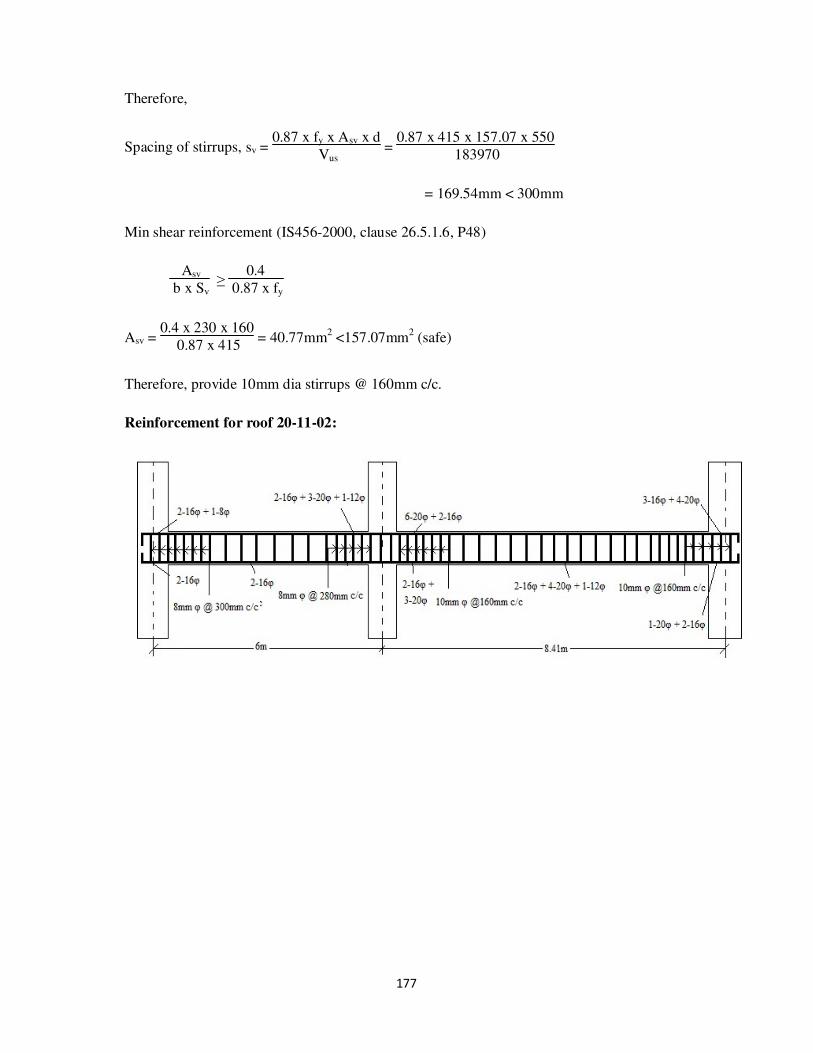
177
Therefore,
Spacing of stirrups, sv = 0.87 x fy x Asv x d
Vus =
0.87 x 415 x 157.07 x 550
183970
= 169.54mm < 300mm
Min shear reinforcement (IS456-2000, clause 26.5.1.6, P48)
Asv
b x Sv ≥
0.4
0.87 x fy
Asv = 0.4 x 230 x 160
0.87 x 415 = 40.77mm
2 <157.07mm
2 (safe)
Therefore, provide 10mm dia stirrups @ 160mm c/c.
Reinforcement for roof 20-11-02:

178
c. Beam 24-15 and Beam 15-06

179
ROOF – Same as in case of roof 20-11-12
FLOOR:
The moments acting on the beam are:
At left support (Ast1):
Moment due to external load (Mu) = 95.08 KN-m
Mu’limit = 0.138 x fck x b x d2
= 0.138 x 20 x 230 x (550)2 = 192.027 x 10
6 N-mm
= 192.027 KN-m
Mu < Mu’limit , therefore design as singly reinforced beam.
To find Ast1:
Mu’limit = 0.87 x fy x Ast1 x d x (1 - fy x Ast1
fck x b x d )
95.08 x 106 = 0.87 x 415 x Ast1 x 550 x (1 - 415 x Ast1
20 x 230 x 550 )
Ast1 = 523.81 mm2
Between the supports (Ast2):
Span moment = 89.37 KN-m
Effective width of flange (bf) = l06
+ (6 x Df) + bw
l0 = 0.7 x l = 0.7 x 6000 = 4200 mm

180
Therefore, bf = 4200
6 + (6 x 120) + 230
= 1650 mm
Therefore Mu’limit = 0.36 x fck x bf x Df x (d – 0.42Df)
= 0.36 x 20 x 1590 x 120 x (550 – 0.42 x 120)
= 712.23 KN-m
Mu < Mu’limit
Ast:
89.37 x 106 = 0.87 x 415 x Ast2 x 550 x (1-
415 x Ast2
20 x 230 x 550 )
Ast2 = 489.33 mm2
At right support (Ast3):
Moment due to external load (Mu) = 208.43 KN-m
Mu’limit = 0.138 x fck x b x d2
= 0.138 x 20 x 230 x (550)2 = 192.027 x 10
6 N-mm
= 192.027 KN-m
Mu > Mu’limit , therefore design as doubly reinforced beam.
Consider d'
d =
50
550 = 0.1
Therefore, fsc = 353 N/mm2
Area of steel in compression (Asc):
Asc = Mu - Mu’limit
fsc x (d - d') =
(208.43 - 192.027) x 106
353 x (550 - 50) =92.94 mm
2
To find Ast1:
181
Mu’limit = 0.87 x fy x Ast1 x d x (1 - fy x Ast1
fck x b x d )
192.027 x 106 = 0.87 x 415 x Ast1 x 550 x (1 -
415 x Ast1
20 x 230 x 550 )
Ast1 = 1205.32 mm2
To find Ast2:
Ast2 = fsc x Asc
0.87 x fy =
353 x 92.94
0.87 x 415 = 90.87 mm2
Ast3 = Ast1 + Ast2 = 1205.32 + 90.87 = 1296.19 mm2
At support (Ast4):
Moment due to external load (Mu) = 280.82 KN-m
Mu’limit = 0.138 x fck x b x d2
= 0.138 x 20 x 230 x (550)2 = 192.027 x 10
6 N-mm
= 192.027 KN-m
Mu > Mu’limit , therefore design as doubly reinforced beam.
Consider d'
d =
50
550 = 0.1
Therefore, fsc = 353 N/mm2
Area of steel in compression (Asc):
Asc = Mu - Mu’limit
fsc x (d - d') =
(280.82 - 192.027) x 106
353 x (550 - 50) =503.08 mm
2
To find Ast1:
Mu’limit = 0.87 x fy x Ast1 x d x (1 - fy x Ast1
fck x b x d )
192.027 x 106 = 0.87 x 415 x Ast1 x 550 x (1 - 415 x Ast1
20 x 230 x 550 )
Ast1 = 1205.32 mm2

182
To find Ast2:
Ast2 = fsc x Asc
0.87 x fy =
353 x 503.08
0.87 x 415 = 491.86 mm
2
Ast4 = Ast1 + Ast2 = 1205.32 + 491.86 = 1697.18 mm2
Between the supports (Ast5):
Span moment = 166.85 KN-m
Effective width of flange (bf) = l06
+ (6 x Df) + bw
l0 = 0.7 x l = 0.7 x 8410 = 5887 mm
Therefore, bf = 5887
6 + (6 x 120) + 230
= 1931.17 mm
Therefore Mu’limit = 0.36 x fck x bf x Df x (d – 0.42Df)
= 0.36 x 20 x 1931.7 x 120 x (550 – 0.42 x 120)
= 833.83 KN-m
Mu < Mu’limit
Ast:
166.85 x 106 = 0.87 x 415 x Ast2 x 550 x (1-
415 x Ast2
20 x 230 x 550 )
Ast5 = 1006.35 mm2
At right end (Ast6):
Moment due to external load (Mu) = 211.34 KN-m
Mu’limit = 0.138 x fck x b x d2
= 0.138 x 20 x 230 x (550)2 = 192.027 x 10
6 N-mm
= 192.027 KN-m
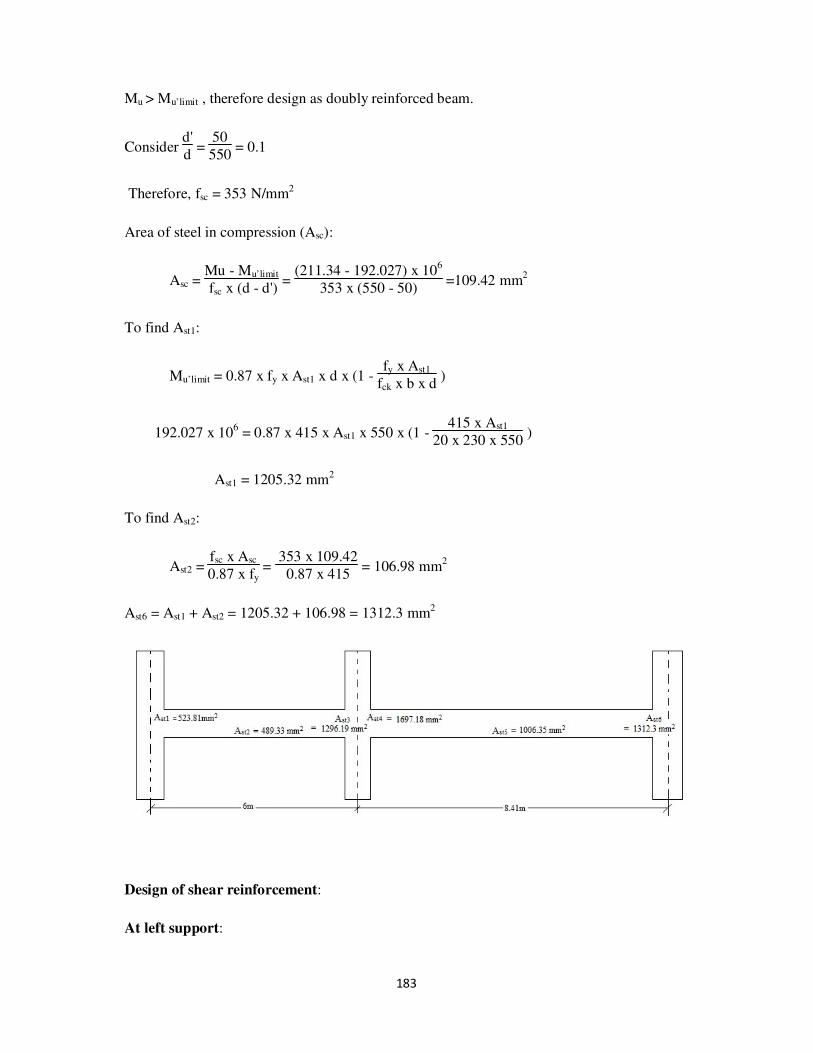
183
Mu > Mu’limit , therefore design as doubly reinforced beam.
Consider d'
d =
50
550 = 0.1
Therefore, fsc = 353 N/mm2
Area of steel in compression (Asc):
Asc = Mu - Mu’limit
fsc x (d - d') =
(211.34 - 192.027) x 106
353 x (550 - 50) =109.42 mm
2
To find Ast1:
Mu’limit = 0.87 x fy x Ast1 x d x (1 - fy x Ast1
fck x b x d )
192.027 x 106 = 0.87 x 415 x Ast1 x 550 x (1 -
415 x Ast1
20 x 230 x 550 )
Ast1 = 1205.32 mm2
To find Ast2:
Ast2 = fsc x Asc
0.87 x fy =
353 x 109.42
0.87 x 415 = 106.98 mm
2
Ast6 = Ast1 + Ast2 = 1205.32 + 106.98 = 1312.3 mm2
Design of shear reinforcement:
At left support:
184
End shear = (Vu) = 133.66 KN
Nominal shear stress, v = Vu
b x d =
133.66 x 10³
230 x 550 = 1.06 N/mm
2
Ast = 523.81 mm2
Consider Pt = 100 xAst
b x d =
100 x 523.81
230 x 550 = 0.42
From IS 456-2000, Table 19:
Pt c
0.25 0.36
0.42 ?
0.5 0.48
Therefore, c = 0.36 + 0.48-0.36
0.5-0.25 x (0.42-0.25) = 0.44 N/mm
2
Therefore, v > c,
Stirrups are designed for shear Vus = Vu - cbd
= (133.66 x 10³) – (0.44 x 230 x 550)
= 78000N
Assuming 8mmφ- 2legged stirrups
Asv = 2 x π x 8
2
4 = 100.53mm
2
Therefore,
Spacing of stirrups, sv = 0.87 x fy x Asv x d
Vus =
0.87 x 415 x 100.53 x 550
78000
= 255.94mm <300mm
Min shear reinforcement (IS456-2000, clause 26.5.1.6, P48)

185
Asv
b x Sv ≥
0.4
0.87 x fy
Asv = 0.4 x 230 x 250
0.87 x 415 = 63.7mm
2 <100.5mm
2 (safe)
Therefore, provide 8mm dia stirrups @ 250mm c/c.
At middle support:
End shear = (Vu) = 166.87 KN
Nominal shear stress, v = Vu
b x d =
166.87 x 10³
230 x 550 = 1.32 N/mm
2
Ast = 1296.19 mm2
Consider Pt = 100 xAst
b x d =
100 x 1296.19
230 x 550 = 1.03
From IS 456-2000, Table 19:
Pt c
1.00 0.62
1.03 ?
1.25 0.67
Therefore, c = 0.62 + 0.67-0.62
1.25-1 x (1.03-1) = 0.63 N/mm
2
Therefore, v > c,
Stirrups are designed for shear Vus = Vu - cbd
= (166.87 x 10³) – (0.63 x 230 x 550)
= 87175N
Assuming 8mmφ- 2legged stirrups
Asv = 2 x π x 8
2
4 = 100.53mm
2

186
Therefore,
Spacing of stirrups, sv = 0.87 x fy x Asv x d
Vus =
0.87 x 415 x 100.53 x 550
87175
= 229mm < 300mm
Min shear reinforcement (IS456-2000, clause 26.5.1.6, P48)
Asv
b x Sv ≥
0.4
0.87 x fy
Asv = 0.4 x 230 x 220
0.87 x 415 = 56.05mm
2 <100.5mm
2 (safe)
Therefore, provide 8mm dia stirrups @ 220mm c/c.
At middle support:
End shear = (Vu) = 200.56 KN
Nominal shear stress, v = Vu
b x d =
200.56 x 10³
230 x 550 = 1.59 N/mm2
Ast = 1697.18 mm2
Consider Pt = 100 xAst
b x d =
100 x 1697.18
230 x 550 = 1.34
From IS 456-2000, Table 19:
Pt c
1.25 0.67
1.34 ?
1.50 0.72
Therefore, c = 0.67 + 0.72-0.67
1.5-1.25 x (1.34-1.25) = 0.69 N/mm2
Therefore, v > c,
Stirrups are designed for shear Vus = Vu - cbd

187
= (200.56 x 10³) – (0.69 x 230 x 550)
= 113275N
Assuming 10mmφ- 2legged stirrups
Asv = 2 x π x 102
4 = 157.07mm2
Therefore,
Spacing of stirrups, sv = 0.87 x fy x Asv x d
Vus =
0.87 x 415 x 157.07 x 550
113275
= 275.35mm < 300mm
Min shear reinforcement (IS456-2000, clause 26.5.1.6, P48)
Asv
b x Sv ≥
0.4
0.87 x fy
Asv = 0.4 x 230 x 270
0.87 x 415 = 68.8mm2 <157.07mm2 (safe)
Therefore, provide 10mm dia stirrups @ 270mm c/c.
At right support:
End shear = (Vu) = 185.35 KN
Nominal shear stress, v = Vu
b x d =
185.35 x 10³
230 x 550 = 1.47 N/mm
2
Ast = 1312.3 mm2
Consider Pt = 100 xAst
b x d =
100 x 1312.3
230 x 550 = 1
From IS 456-2000, Table 19:
Pt c

188
1 0.62
Therefore, c = 0.62 N/mm2
Therefore, v > c,
Stirrups are designed for shear Vus = Vu - cbd
= (185.35 x 10³) – (0.62 x 230 x 550)
= 106920N
Assuming 10mmφ- 2legged stirrups
Asv = 2 x π x 10
2
4 = 157.07mm
2
Therefore,
Spacing of stirrups, sv = 0.87 x fy x Asv x d
Vus =
0.87 x 415 x 157.07 x 550
106920
= 291mm < 300mm
Min shear reinforcement (IS456-2000, clause 26.5.1.6, P48)
Asv
b x Sv ≥
0.4
0.87 x fy
Asv = 0.4 x 230 x 290
0.87 x 415 = 73.9mm2 <157.07mm2 (safe)
Therefore, provide 10mm dia stirrups @ 290mm c/c.
Reinforcement for roof 24-15-06:

189
d. Beam 25-16 and Beam 16-07

190
ROOF – Same as 20-11-02

191
FLOOR:
The moments acting on the beam are:
At left support (Ast1):
Moment due to external load (Mu) = 85.69 KN-m
Mu’limit = 0.138 x fck x b x d2
= 0.138 x 20 x 230 x (550)2 = 192.027 x 10
6 N-mm
= 192.027 KN-m
Mu < Mu’limit , therefore design as singly reinforced beam.
To find Ast1:
Mu’limit = 0.87 x fy x Ast1 x d x (1 - fy x Ast1
fck x b x d )
85.69 x 106 = 0.87 x 415 x Ast1 x 550 x (1 - 415 x Ast1
20 x 230 x 550 )
Ast1 = 467.34 mm2
Between the supports (Ast2):
Span moment = 80.45 KN-m
Effective width of flange (bf) = l06
+ (6 x Df) + bw
l0 = 0.7 x l = 0.7 x 6000 = 4200 mm

192
Therefore, bf = 4200
6 + (6 x 120) + 230
= 1650 mm
Therefore Mu’limit = 0.36 x fck x bf x Df x(d – 0.42Df)
= 0.36 x 20 x 1590 x 120 x (550 – 0.42 x 120)
= 712.23 KN-m
Mu < Mu’limit
Ast:
80.45 x 106 = 0.87 x 415 x Ast2 x 550 x (1-
415 x Ast2
20 x 230 x 550 )
Ast2 = 436.37 mm2
At right support (Ast3):
Moment due to external load (Mu) = 218.95 KN-m
Mu’limit = 0.138 x fck x b x d2
= 0.138 x 20 x 230 x (550)2 = 192.027 x 10
6 N-mm
= 192.027 KN-m
Mu > Mu’limit , therefore design as doubly reinforced beam.
Consider d'
d =
50
550 = 0.1
Therefore, fsc = 353 N/mm2
Area of steel in compression (Asc):
Asc = Mu - Mu’limit
fsc x (d - d') =
(218.95 - 192.027) x 106
353 x (550 - 50) =152.54 mm
2
To find Ast1:
Mu’limit = 0.87 x fy x Ast1 x d x (1 - fy x Ast1
fck x b x d )

193
192.027 x 106 = 0.87 x 415 x Ast1 x 550 x (1 - 415 x Ast1
20 x 230 x 550 )
Ast1 = 1205.32 mm2
To find Ast2:
Ast2 = fsc x Asc
0.87 x fy =
353 x 152.54
0.87 x 415 = 149.14 mm
2
Ast3 = Ast1 + Ast2 = 1205.32 + 149.14 = 1354.46 mm2
At support (Ast4):
Moment due to external load (Mu) = 343.47 KN-m
Mu’limit = 0.138 x fck x b x d2
= 0.138 x 20 x 230 x (550)2 = 192.027 x 10⁶ N-mm
= 192.027 KN-m
Mu > Mu’limit , therefore design as doubly reinforced beam.
Consider d'
d =
50
550 = 0.1
Therefore, fsc = 353 N/mm2
Area of steel in compression (Asc):
Asc = Mu - Mu’limit
fsc x (d - d') =
(343.47 - 192.027) x 106
353 x (550 - 50) =858.03 mm2
To find Ast1:
Mu’limit = 0.87 x fy x Ast1 x d x (1 - fy x Ast1
fck x b x d )
192.027 x 106 = 0.87 x 415 x Ast1 x 550 x (1 -
415 x Ast1
20 x 230 x 550 )
Ast1 = 1205.32 mm2

194
To find Ast2:
Ast2 = fsc x Asc
0.87 x fy =
353 x 858.03
0.87 x 415 = 838.9 mm
2
Ast4 = Ast1 + Ast2 = 1205.32 + 838.9 = 2044.22 mm2
Between the supports (Ast5):
Span moment = 210.5 KN-m
Effective width of flange (bf) = l06
+ (6 x Df) + bw
l0 = 0.7 x l = 0.7 x 8410 = 5887 mm
Therefore, bf = 5887
6 + (6 x 120) + 230
= 1931.17 mm
Therefore Mu’limit = 0.36 x fck x bf x Df x(d – 0.42Df)
= 0.36 x 20 x 1931.7 x 120 x (550 – 0.42 x 120)
= 833.83 KN-m
Mu < Mu’limit
Ast:
210.5 x 106 = 0.87 x 415 x Ast2 x 550 x (1-
415 x Ast2
20 x 230 x 550 )
Ast5 = 1366.21 mm2
At right end (Ast6):
Moment due to external load (Mu) = 268.55 KN-m
Mu’limit = 0.138 x fck x b x d2
= 0.138 x 20 x 230 x (550)2 = 192.027 x 10
6 N-mm
= 192.027 KN-m

195
Mu > Mu’limit , therefore design as doubly reinforced beam.
Consider d'
d =
50
550 = 0.1
Therefore, fsc = 353 N/mm2
Area of steel in compression (Asc):
Asc = Mu - Mu’limit
fsc x (d - d') =
(268.55 - 192.027) x 106
353 x (550 - 50) =433.56 mm
2
To find Ast1:
Mu’limit = 0.87 x fy x Ast1 x d x (1 - fy x Ast1
fck x b x d )
192.027 x 106 = 0.87 x 415 x Ast1 x 550 x (1 -
415 x Ast1
20 x 230 x 550 )
Ast1 = 1205.32 mm2
To find Ast2:
Ast2 = fsc x Asc
0.87 x fy =
353 x 433.56
0.87 x 415 = 423.9 mm
2
Ast6 = Ast1 + Ast2 = 1205.32 + 423.9 = 1629.22 mm2
Design of shear reinforcement:
At left support:
End shear = (Vu) = 120.89 KN
196
Nominal shear stress, v = Vu
b x d =
120.89 x 10³
230 x 550 = 0.96 N/mm2
Ast = 467.34 mm2
Consider Pt = 100 xAst
b x d =
100 x 467.34
230 x 550 = 0.37
From IS 456-2000, Table 19:
Pt c
0.25 0.36
0.37 ?
0.5 0.48
Therefore, c = 0.36 + 0.48-0.36
0.5-0.25 x (0.37-0.25) = 0.42 N/mm
2
Therefore, v > c,
Stirrups are designed for shear Vus = Vu - cbd
= (120.89 x 10³) – (0.42 x 230 x 550)
= 67760N
Assuming 8mmφ- 2legged stirrups
Asv = 2 x π x 8
2
4 = 100.53mm
2
Therefore,
Spacing of stirrups, sv = 0.87 x fy x Asv x d
Vus =
0.87 x 415 x 100.53 x 550
67760
= 294mm <300mm
Min shear reinforcement (IS456-2000, clause 26.5.1.6, P48)
Asv
b x Sv ≥
0.4
0.87 x fy

197
Asv = 0.4 x 230 x 290
0.87 x 415 = 73.9mm2 <100.5mm2 (safe)
Therefore, provide 8mm dia stirrups @ 290mm c/c.
At middle support:
End shear = (Vu) = 158.11 KN
Nominal shear stress, v = Vu
b x d =
158.11 x 10³
230 x 550 = 1.25 N/mm
2
Ast = 1354.46 mm2
Consider Pt = 100 xAst
b x d =
100 x 1354.46
230 x 550 = 1.07
From IS 456-2000, Table 19:
Pt c
1.00 0.62
1.07 ?
1.25 0.67
Therefore, c = 0.62 + 0.67-0.62
1.25-1 x (1.07-1) = 0.634 N/mm2
Therefore, v > c,
Stirrups are designed for shear Vus = Vu - cbd
= (158.11x 10³) – (0.634 x 230 x 550)
= 77909N
Assuming 8mmφ- 2legged stirrups
Asv = 2 x π x 82
4 = 100.53mm2

198
Therefore,
Spacing of stirrups, sv = 0.87 x fy x Asv x d
Vus =
0.87 x 415 x 100.53 x 550
77909
= 256.24mm < 300mm
Min shear reinforcement (IS456-2000, clause 26.5.1.6, P48)
Asv
b x Sv ≥
0.4
0.87 x fy
Asv = 0.4 x 230 x 250
0.87 x 415 = 63.7mm
2 <100.5mm
2 (safe)
Therefore, provide 8mm dia stirrups @ 250mm c/c.
At middle support:
End shear = (Vu) = 251.1 KN
Nominal shear stress, v = Vu
b x d =
251.1 x 10³
230 x 550 = 2 N/mm2
Ast = 2044.2 mm2
Consider Pt = 100 xAst
b x d =
100 x 2044.2
230 x 550 = 1.62
From IS 456-2000, Table 19:
Pt c
1.5 0.72
1.62 ?
1.75 0.75
Therefore, c = 0.72 + 0.75-0.72
1.75-1.5 x (1.62-1.5) = 0.73 N/mm2
Therefore, v > c,

199
Stirrups are designed for shear Vus = Vu - cbd
= (251.1 x 10³) – (0.73 x 230 x 550)
= 158755N
Assuming 10mmφ- 2legged stirrups
Asv = 2 x π x 10
2
4 = 157.07mm
2
Therefore,
Spacing of stirrups, sv = 0.87 x fy x Asv x d
Vus =
0.87 x 415 x 157.07 x 550
158755
= 196.5mm < 300mm
Min shear reinforcement (IS456-2000, clause 26.5.1.6, P48)
Asv
b x Sv ≥
0.4
0.87 x fy
Asv = 0.4 x 230 x 190
0.87 x 415 = 48.41mm
2 <157.07mm
2 (safe)
Therefore, provide 10mm dia stirrups @ 190mm c/c.
At right support:
End shear = (Vu) = 234.86 KN
Nominal shear stress, v = Vu
b x d =
234.86 x 10³
230 x 550 = 1.86 N/mm2
Ast = 1629.22 mm2
Consider Pt = 100 xAst
b x d =
100 x 1629.22
230 x 550 = 1.29
From IS 456-2000, Table 19:
Pt c
1.25 0.67

200
1.29 ?
1.5 0.72
Therefore, c = = 0.67 + 0.72-0.67
1.5-1.25 x (1.29-1.25) = 0.68 N/mm
2
Therefore, v > c,
Stirrups are designed for shear Vus = Vu - cbd
= (234.86 x 10³) – (0.68 x 230 x 550)
= 148840N
Assuming 10mmφ- 2legged stirrups
Asv = 2 x π x 102
4 = 157.07mm2
Therefore,
Spacing of stirrups, sv = 0.87 x fy x Asv x d
Vus =
0.87 x 415 x 157.07 x 550
148840
= 209.56mm < 300mm
Min shear reinforcement (IS456-2000, clause 26.5.1.6, P48)
Asv
b x Sv ≥
0.4
0.87 x fy
Asv = 0.4 x 230 x 200
0.87 x 415 = 50.96mm2 <157.07mm2 (safe)
Therefore, provide 10mm dia stirrups @ 200mm c/c.

201
Reinforcement for roof 25-16-07
e. Beam 26-17 and Beam 17-08

202
ROOF – Same as 20-11-02

203
FLOOR:
The moments acting on the beam are:
At left support (Ast1):
Moment due to external load (Mu) = 73.1 KN-m
Mu’limit = 0.138 x fck x b x d2
= 0.138 x 20 x 230 x (550)2 = 192.027 x 10
6 N-mm
= 192.027 KN-m
Mu < Mu’limit , therefore design as singly reinforced beam.
To find Ast1:
Mu’limit = 0.87 x fy x Ast1 x d x (1 - fy x Ast1
fck x b x d )
73.1 x 106 = 0.87 x 415 x Ast1 x 550 x (1 - 415 x Ast1
20 x 230 x 550 )
Ast1 = 393.52 mm2
Between the supports (Ast2):
Span moment = 68.48 KN-m
Effective width of flange (bf) = l06
+ (6 x Df) + bw
l0 = 0.7 x l = 0.7 x 6000 = 4200 mm

204
Therefore, bf = 4200
6 + (6 x 120) + 230
= 1650 mm
Therefore Mu’limit = 0.36 x fck x bf x Df x(d – 0.42Df)
= 0.36 x 20 x 1590 x 120 x (550 – 0.42 x 120)
= 712.23 KN-m
Mu < Mu’limit
Ast:
68.48 x 106 = 0.87 x 415 x Ast2 x 550 x (1-
415 x Ast2
20 x 230 x 550 )
Ast2 = 366.94 mm2
At right support (Ast3):
Moment due to external load (Mu) = 185.08 KN-m
Mu’limit = 0.138 x fck x b x d2
= 0.138 x 20 x 230 x (550)2 = 192.027 x 10
6 N-mm
= 192.027 KN-m
Mu < Mu’limit , therefore design as singly reinforced beam.
To find Ast3:
Mu’limit = 0.87 x fy x Ast3 x d x (1 - fy x Ast3
fck x b x d )
185.08 x 106 = 0.87 x 415 x Ast3 x 550 x (1 - 415 x Ast3
20 x 230 x 550 )
Ast3 = 1148.33 mm2
At support (Ast4):
Moment due to external load (Mu) = 297.26 KN-m

205
Mu’limit = 0.138 x fck x b x d2
= 0.138 x 20 x 230 x (550)2 = 192.027 x 10
6 N-mm
= 192.027 KN-m
Mu > Mu’limit , therefore design as doubly reinforced beam.
Consider d'
d =
50
550 = 0.1
Therefore, fsc = 353 N/mm2
Area of steel in compression (Asc):
Asc = Mu - Mu’limit
fsc x (d - d') =
(297.26 - 192.027) x 106
353 x (550 - 50) =596.22 mm2
To find Ast1:
Mu’limit = 0.87 x fy x Ast1 x d x (1 - fy x Ast1
fck x b x d )
192.027 x 106 = 0.87 x 415 x Ast1 x 550 x (1 -
415 x Ast1
20 x 230 x 550 )
Ast1 = 1205.32 mm2
To find Ast2:
Ast2 = fsc x Asc
0.87 x fy =
353 x 596.22
0.87 x 415 = 582.93 mm2
Ast4 = Ast1 + Ast2 = 1205.32 + 582.93 = 1788.25 mm2
Between the supports (Ast5):
Span moment = 183.9 KN-m
Effective width of flange (bf) = l06
+ (6 x Df) + bw
l0 = 0.7 x l = 0.7 x 8410 = 5887 mm

206
Therefore, bf = 5887
6 + (6 x 120) + 230
= 1931.17 mm
Therefore Mu’limit = 0.36 x fck x bf x Df x(d – 0.42Df)
= 0.36 x 20 x 1931.7 x 120 x (550 – 0.42 x 120)
= 833.83 KN-m
Mu < Mu’limit
Ast:
183.9 x 106 = 0.87 x 415 x Ast2 x 550 x (1-
415 x Ast2
20 x 230 x 550 )
Ast5 = 1138.82 mm2
At right end (Ast6):
Moment due to external load (Mu) = 234.45 KN-m
Mu’limit = 0.138 x fck x b x d2
= 0.138 x 20 x 230 x (550)2 = 192.027 x 10
6 N-mm
= 192.027 KN-m
Mu > Mu’limit , therefore design as doubly reinforced beam.
Consider d'
d =
50
550 = 0.1
Therefore, fsc = 353 N/mm2
Area of steel in compression (Asc):
Asc = Mu - Mu’limit
fsc x (d - d') =
(234.45 - 192.027) x 106
353 x (550 - 50) =240.36 mm
2
To find Ast1:
Mu’limit = 0.87 x fy x Ast1 x d x (1 - fy x Ast1
fck x b x d )

207
192.027 x 106 = 0.87 x 415 x Ast1 x 550 x (1 - 415 x Ast1
20 x 230 x 550 )
Ast1 = 1205.32 mm2
To find Ast2:
Ast2 = fsc x Asc
0.87 x fy =
353 x 240.36
0.87 x 415 = 235 mm
2
Ast6 = Ast1 + Ast2 = 1205.32 + 235 = 1440.32 mm2
Design of shear reinforcement:
At left support:
End shear = (Vu) = 101.13 KN
Nominal shear stress, v = Vu
b x d =
101.13 x 10³
230 x 550 = 0.8 N/mm
2
Ast = 393.52 mm2
Consider Pt = 100 xAst
b x d =
100 x 393.52
230 x 550 = 0.31
From IS 456-2000, Table 19:
Pt c
0.25 0.36
0.31 ?
0.5 0.48

208
Therefore, c = 0.36 + 0.48-0.36
0.5-0.25 x (0.31-0.25) = 0.39 N/mm2
Therefore, v > c,
Stirrups are designed for shear Vus = Vu - cbd
= (101.13 x 10³) – (0.39 x 230 x 550)
= 51795N
Assuming 8mmφ- 2legged stirrups
Asv = 2 x π x 8
2
4 = 100.53mm
2
Therefore,
Spacing of stirrups, sv = 0.87 x fy x Asv x d
Vus =
0.87 x 415 x 100.53 x 550
51795
= 385.42mm >300mm
Provide spacing = 300mm
Vus = 0.87 x fy x Asv x d
sv =
0.87 x 415 x 100.53 x 550
300 = 66543.32N
Min shear reinforcement (IS456-2000, clause 26.5.1.6, P48)
Asv
b x Sv ≥
0.4
0.87 x fy
Asv = 0.4 x 230 x 300
0.87 x 415 = 76.44 mm2 <100.5mm2 (safe)
Therefore, provide 8mm dia stirrups @ 300mm c/c.
At middle support:
End shear = (Vu) = 131.2 KN
Nominal shear stress, v = Vu
b x d =
131.2 x 10³
230 x 550 = 1.04 N/mm
2

209
Ast = 1148.33 mm2
Consider Pt = 100 xAst
b x d =
100 x 1148.33
230 x 550 = 0.91
From IS 456-2000, Table 19:
Pt c
0.75 0.56
0.91 ?
1.00 0.62
Therefore, c = 0.56 + 0.62-0.56
1-0.75 x (0.91-0.75) = 0.6 N/mm
2
Therefore, v > c,
Stirrups are designed for shear Vus = Vu - cbd
= (131.2x 10³) – (0.6 x 230 x 550)
= 55300N
Assuming 8mmφ- 2legged stirrups
Asv = 2 x π x 82
4 = 100.53mm2
Therefore,
Spacing of stirrups, sv = 0.87 x fy x Asv x d
Vus =
0.87 x 415 x 100.53 x 550
55300
= 361mm > 300mm
Provide spacing = 300mm
Vus = 0.87 x fy x Asv x d
sv =
0.87 x 415 x 100.53 x 550
300 = 66543.32N
Min shear reinforcement (IS456-2000, clause 26.5.1.6, P48)

210
Asv
b x Sv ≥
0.4
0.87 x fy
Asv = 0.4 x 230 x 300
0.87 x 415 = 76.44 mm
2 <100.5mm
2 (safe)
Therefore, provide 8mm dia stirrups @ 300mm c/c.
At middle support:
End shear = (Vu) = 218.47 KN
Nominal shear stress, v = Vu
b x d =
218.47 x 10³
230 x 550 = 1.73 N/mm
2
Ast = 1788.25 mm2
Consider Pt = 100 xAst
b x d =
100 x 1788.25
230 x 550 = 1.42
From IS 456-2000, Table 19:
Pt c
1.25 0.67
1.42 ?
1.5 0.72
Therefore, c = 0.67 + 0.72-0.67
1.5-1.25 x (1.42-1.25) = 0.71 N/mm
2
Therefore, v > c,
Stirrups are designed for shear Vus = Vu - cbd
= (218.47 x 10³) – (0.71 x 230 x 550)
= 128655N
Assuming 10mmφ- 2legged stirrups
Asv = 2 x π x 10
2
4 = 157.07mm
2

211
Therefore,
Spacing of stirrups, sv = 0.87 x fy x Asv x d
Vus =
0.87 x 415 x 157.07 x 550
128655
= 242.5mm < 300mm
Min shear reinforcement (IS456-2000, clause 26.5.1.6, P48)
Asv
b x Sv ≥
0.4
0.87 x fy
Asv = 0.4 x 230 x 240
0.87 x 415 = 61.16mm
2 <157.07mm
2 (safe)
Therefore, provide 10mm dia stirrups @ 240mm c/c.
At right support:
End shear = (Vu) = 204.57 KN
Nominal shear stress, v = Vu
b x d =
204.57 x 10³
230 x 550 = 1.62 N/mm2
Ast = 1400.32 mm2
Consider Pt = 100 xAst
b x d =
100 x 1400.32
230 x 550 = 1.11
From IS 456-2000, Table 19:
Pt c
1.00 0.62
1.11 ?
1.25 0.67
Therefore, c = = 0.62 + 0.67-0.62
1.25-1.00 x (1.11-1.00) = 0.64 N/mm2
Therefore, v > c,

212
Stirrups are designed for shear Vus = Vu - cbd
= (204.57 x 10³) – (0.64 x 230 x 550)
= 123610N
Assuming 10mmφ- 2legged stirrups
Asv = 2 x π x 10
2
4 = 157.07mm
2
Therefore,
Spacing of stirrups, sv = 0.87 x fy x Asv x d
Vus =
0.87 x 415 x 157.07 x 550
123610
= 252.33mm < 300mm
Min shear reinforcement (IS456-2000, clause 26.5.1.6, P48)
Asv
b x Sv ≥
0.4
0.87 x fy
Asv = 0.4 x 230 x 250
0.87 x 415 = 63.7mm
2 <157.07mm
2 (safe)
Therefore, provide 10mm dia stirrups @ 200mm c/c.
Reinforcement for roof 26-17-08
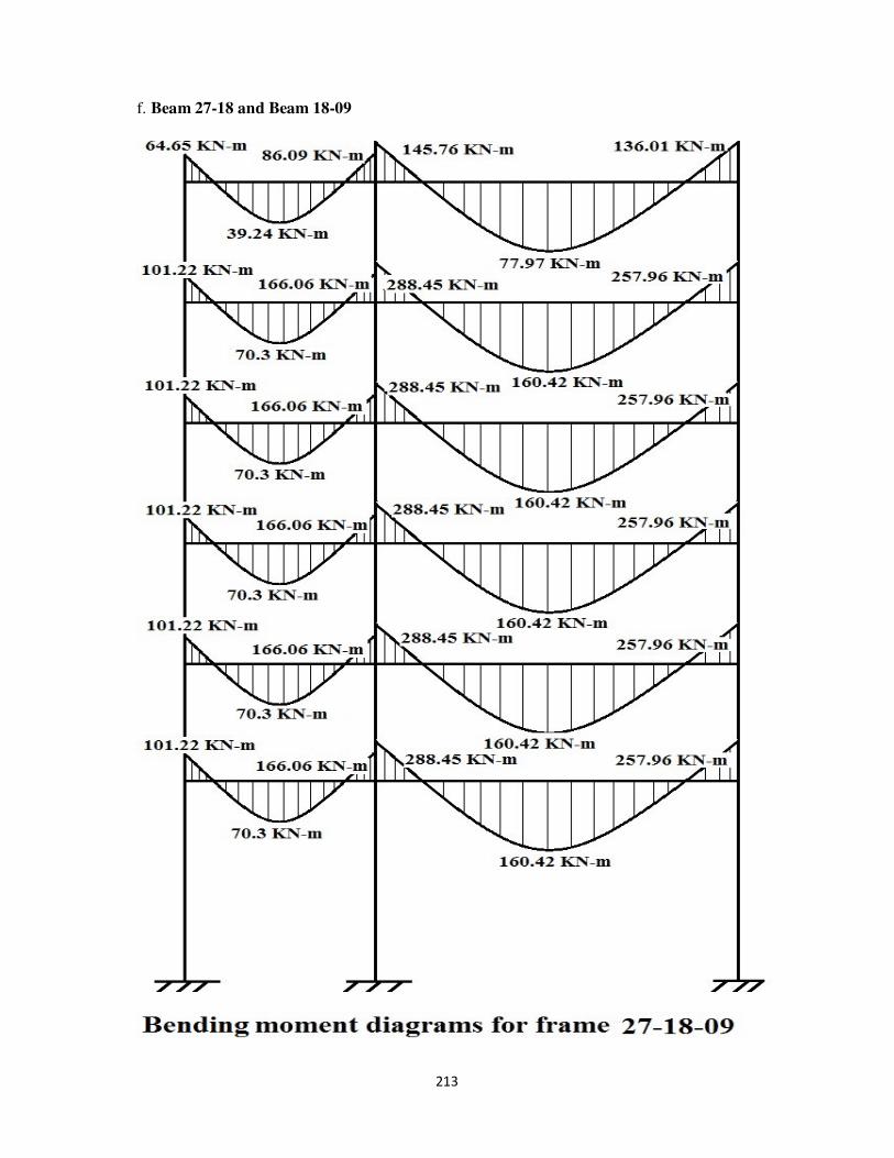
213
f. Beam 27-18 and Beam 18-09
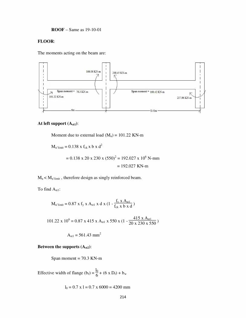
214
ROOF – Same as 19-10-01
FLOOR:
The moments acting on the beam are:
At left support (Ast1):
Moment due to external load (Mu) = 101.22 KN-m
Mu’limit = 0.138 x fck x b x d2
= 0.138 x 20 x 230 x (550)2 = 192.027 x 10⁶ N-mm
= 192.027 KN-m
Mu < Mu’limit , therefore design as singly reinforced beam.
To find Ast1:
Mu’limit = 0.87 x fy x Ast1 x d x (1 - fy x Ast1
fck x b x d )
101.22 x 106 = 0.87 x 415 x Ast1 x 550 x (1 -
415 x Ast1
20 x 230 x 550 )
Ast1 = 561.43 mm2
Between the supports (Ast2):
Span moment = 70.3 KN-m
Effective width of flange (bf) = l06
+ (6 x Df) + bw
l0 = 0.7 x l = 0.7 x 6000 = 4200 mm
215
Therefore, bf = 4200
6 + (6 x 120) + 230
= 1650 mm
Therefore Mu’limit = 0.36 x fck x bf x Df x(d – 0.42Df)
= 0.36 x 20 x 1590 x 120 x (550 – 0.42 x 120)
= 712.23 KN-m
Mu < Mu’limit
Ast:
70.3 x 106 = 0.87 x 415 x Ast2 x 550 x (1-
415 x Ast2
20 x 230 x 550 )
Ast2 = 377.38 mm2
At right support (Ast3):
Moment due to external load (Mu) = 166.06 KN-m
Mu’limit = 0.138 x fck x b x d2
= 0.138 x 20 x 230 x (550)2 = 192.027 x 10
6 N-mm
= 192.027 KN-m
Mu < Mu’limit , therefore design as singly reinforced beam.
To find Ast3:
Mu’limit = 0.87 x fy x Ast3 x d x (1 - fy x Ast3
fck x b x d )
166.06 x 106 = 0.87 x 415 x Ast3 x 550 x (1 - 415 x Ast3
20 x 230 x 550 )
Ast3 = 1000.42 mm2
At support (Ast4):
Moment due to external load (Mu) = 288.45 KN-m

216
Mu’limit = 0.138 x fck x b x d2
= 0.138 x 20 x 230 x (550)2 = 192.027 x 10
6 N-mm
= 192.027 KN-m
Mu > Mu’limit , therefore design as doubly reinforced beam.
Consider d'
d =
50
550 = 0.1
Therefore, fsc = 353 N/mm2
Area of steel in compression (Asc):
Asc = Mu - Mu’limit
fsc x (d - d') =
(288.45 - 192.027) x 106
353 x (550 - 50) =546.31 mm2
To find Ast1:
Mu’limit = 0.87 x fy x Ast1 x d x (1 - fy x Ast1
fck x b x d )
192.027 x 106 = 0.87 x 415 x Ast1 x 550 x (1 -
415 x Ast1
20 x 230 x 550 )
Ast1 = 1205.32 mm2
To find Ast2:
Ast2 = fsc x Asc
0.87 x fy =
353 x 546.31
0.87 x 415 = 534.13 mm2
Ast4 = Ast1 + Ast2 = 1205.32 + 534.13 = 1739.45 mm2
Between the supports (Ast5):
Span moment = 160.42 KN-m
Effective width of flange (bf) = l06
+ (6 x Df) + bw
l0 = 0.7 x l = 0.7 x 8410 = 5887 mm

217
Therefore, bf = 5887
6 + (6 x 120) + 230
= 1931.17 mm
Therefore Mu’limit = 0.36 x fck x bf x Df x(d – 0.42Df)
= 0.36 x 20 x 1931.7 x 120 x (550 – 0.42 x 120)
= 833.83 KN-m
Mu < Mu’limit
Ast:
160.42 x 106 = 0.87 x 415 x Ast2 x 550 x (1-
415 x Ast2
20 x 230 x 550 )
Ast5 = 958.56 mm2
At right end (Ast6):
Moment due to external load (Mu) = 257.96 KN-m
Mu’limit = 0.138 x fck x b x d2
= 0.138 x 20 x 230 x (550)2 = 192.027 x 10
6 N-mm
= 192.027 KN-m
Mu > Mu’limit , therefore design as doubly reinforced beam.
Consider d'
d =
50
550 = 0.1
Therefore, fsc = 353 N/mm2
Area of steel in compression (Asc):
Asc = Mu - Mu’limit
fsc x (d - d') =
(257.96 - 192.027) x 106
353 x (550 - 50) =373.56 mm
2
To find Ast1:
Mu’limit = 0.87 x fy x Ast1 x d x (1 - fy x Ast1
fck x b x d )
218
192.027 x 106 = 0.87 x 415 x Ast1 x 550 x (1 - 415 x Ast1
20 x 230 x 550 )
Ast1 = 1205.32 mm2
To find Ast2:
Ast2 = fsc x Asc
0.87 x fy =
353 x 373.56
0.87 x 415 = 365.23 mm
2
Ast6 = Ast1 + Ast2 = 1205.32 + 365.23 = 1570.55 mm2
Design of shear reinforcement:
At left support:
End shear = (Vu) = 119.94 KN
Nominal shear stress, v = Vu
b x d =
119.94 x 10³
230 x 550 = 0.95 N/mm
2
Ast = 561.43 mm2
Consider Pt = 100 xAst
b x d =
100 x 561.43
230 x 550 = 0.44
From IS 456-2000, Table 19:
Pt c
0.25 0.36
0.44 ?
0.5 0.48
Therefore, c = 0.36 + 0.48-0.36
0.5-0.25 x (0.44-0.25) = 0.45 N/mm
2
Therefore, v > c,
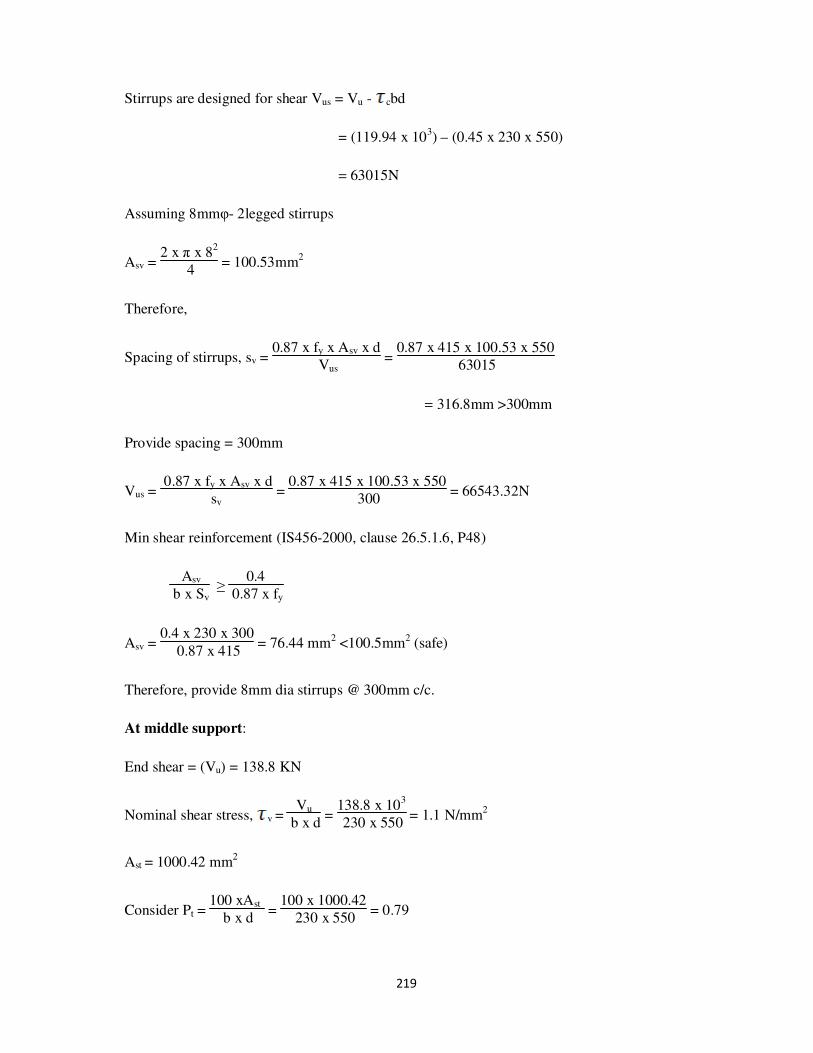
219
Stirrups are designed for shear Vus = Vu - cbd
= (119.94 x 10³) – (0.45 x 230 x 550)
= 63015N
Assuming 8mmφ- 2legged stirrups
Asv = 2 x π x 8
2
4 = 100.53mm
2
Therefore,
Spacing of stirrups, sv = 0.87 x fy x Asv x d
Vus =
0.87 x 415 x 100.53 x 550
63015
= 316.8mm >300mm
Provide spacing = 300mm
Vus = 0.87 x fy x Asv x d
sv =
0.87 x 415 x 100.53 x 550
300 = 66543.32N
Min shear reinforcement (IS456-2000, clause 26.5.1.6, P48)
Asv
b x Sv ≥
0.4
0.87 x fy
Asv = 0.4 x 230 x 300
0.87 x 415 = 76.44 mm2 <100.5mm2 (safe)
Therefore, provide 8mm dia stirrups @ 300mm c/c.
At middle support:
End shear = (Vu) = 138.8 KN
Nominal shear stress, v = Vu
b x d =
138.8 x 10³
230 x 550 = 1.1 N/mm
2
Ast = 1000.42 mm2
Consider Pt = 100 xAst
b x d =
100 x 1000.42
230 x 550 = 0.79

220
From IS 456-2000, Table 19:
Pt c
0.75 0.56
0.79 ?
1.00 0.62
Therefore, c = 0.56 + 0.62-0.56
1-0.75 x (0.79-0.75) = 0.57 N/mm
2
Therefore, v > c,
Stirrups are designed for shear Vus = Vu - cbd
= (138.8x 10³) – (0.57 x 230 x 550)
= 66695N
Assuming 8mmφ- 2legged stirrups
Asv = 2 x π x 82
4 = 100.53mm2
Therefore,
Spacing of stirrups, sv = 0.87 x fy x Asv x d
Vus =
0.87 x 415 x 100.53 x 550
66695
= 300mm
Min shear reinforcement (IS456-2000, clause 26.5.1.6, P48)
Asv
b x Sv ≥
0.4
0.87 x fy
Asv = 0.4 x 230 x 300
0.87 x 415 = 76.44 mm
2 <100.5mm
2 (safe)
Therefore, provide 8mm dia stirrups @ 300mm c/c.

221
At middle support:
End shear = (Vu) = 208.4 KN
Nominal shear stress, v = Vu
b x d =
208.4 x 10³
230 x 550 = 1.65 N/mm
2
Ast = 1739.5mm2
Consider Pt = 100 xAst
b x d =
100 x 1739.5
230 x 550 = 1.38
From IS 456-2000, Table 19:
Pt c
1.25 0.67
1.38 ?
1.5 0.72
Therefore, c = 0.67 + 0.72-0.67
1.5-1.25 x (1.38-1.25) = 0.7 N/mm2
Therefore, v > c,
Stirrups are designed for shear Vus = Vu - cbd
= (208.4 x 10³) – (0.7 x 230 x 550)
= 119850N
Assuming 10mmφ- 2legged stirrups
Asv = 2 x π x 102
4 = 157.07mm2
Therefore,
Spacing of stirrups, sv = 0.87 x fy x Asv x d
Vus =
0.87 x 415 x 157.07 x 550
119850
= 260.25mm < 300mm

222
Min shear reinforcement (IS456-2000, clause 26.5.1.6, P48)
Asv
b x Sv ≥
0.4
0.87 x fy
Asv = 0.4 x 230 x 260
0.87 x 415 = 66.25mm2 <157.07mm2 (safe)
Therefore, provide 10mm dia stirrups @ 260mm c/c.
At right support:
End shear = (Vu) = 200.33 KN
Nominal shear stress, v = Vu
b x d =
200.33 x 10³
230 x 550 = 1.58 N/mm
2
Ast = 1570.5 mm2
Consider Pt = 100 xAst
b x d =
100 x 1570.5
230 x 550 = 1.24
From IS 456-2000, Table 19:
Pt c
1.00 0.62
1.24 ?
1.25 0.67
Therefore, c = = 0.62 + 0.67-0.62
1.25-1.00 x (1.24-1.00) = 0.67 N/mm2
Therefore, v > c,
Stirrups are designed for shear Vus = Vu - cbd
= (200.33 x 10³) – (0.67 x 230 x 550)
= 115575N
Assuming 10mmφ- 2legged stirrups

223
Asv = 2 x π x 102
4 = 157.07mm2
Therefore,
Spacing of stirrups, sv = 0.87 x fy x Asv x d
Vus =
0.87 x 415 x 157.07 x 550
115575
= 269.87mm < 300mm
Min shear reinforcement (IS456-2000, clause 26.5.1.6, P48)
Asv
b x Sv ≥
0.4
0.87 x fy
Asv = 0.4 x 230 x 260
0.87 x 415 = 66.25mm2 <157.07mm2 (safe)
Therefore, provide 10mm dia stirrups @ 260mm c/c.
Reinforcement for roof 27-18-09

224
5. DESIGN OF COLUMNS
Since the loads and moments in the three columns in a frame are different. Each of the
Column is required to be designed separately. However, when entire building is to be
designed, there will be a number of other columns along with each of the above columns to
form a group.
Since exact values of Pu and Mu are known for all storeys for all columns, the column
section will be designed using exact method using charts and tables. Charts are useful for any
column. It is advisable to have curves plotted of Pu-Mu for standard sections normally used in
building design to avoid calculations.
All the columns are subjected to axial loads and uni-axial bending. They will be
designed to resist Pu and Mu for bending about x- x axis which is the major axis.
For frame 19-10-01:
Columns are C19 at left end, C10 at middle and C01 at right end of the frame.
The moments and axial forces are calculated in analysis of frames and design of
beams. We have transverse frames and in these frames the plinth level transverse beams are
absent and longitudinal beams are present at the plinth level.
In each level the types of loads are:
1. Max shear from transverse beams
2. Shear from longitudinal beams
3. Self weight of columns.
But in plinth level shear from transverse beams is absent. We have only two values at the
plinth level
Section: 230mm x 600mm
Cover (d’) = 50mm
Minimum eccentricity (ex,min) = unsupported length
500 +
lateral dimension
30 or
= 20mm

225
Pu – Load acting on the column
Mux,min = ex,min x Pu
MuD = Maximum (Mu, Mux,min)
fck x b x D = 20 x 230 x 600 = 2760000N = 2760 KN
fck x b x D2 = 20 x 230 x (600)
2 = 1676 x 10
6 N-mm = 1676 KN-m

226
For Column 19:
To find MuD:
Storey Length
(mm)
ex,min (mm) Pu (KN) Mux (KN-
m)
Mux,min
(KN-m)
MuD
Roof – 5 3050 26.1 102.83 64.85 2.68 64.85
5-4 2900 25.8 271.485 53.27 7 53.27
4-3 2900 25.8 440.14 53.27 11.36 53.27
3-2 2900 25.8 608.795 53.27 15.71 53.27
2-1 2900 25.8 777.45 53.27 20.06 53.27
1- Plinth 4900 29.8 946.11 53.27 28.19 53.27
Plinth –
Footing
- 29.8 982.185 0 29.27 29.27
By the help of SP16, chart no:32,
From Pu
fck x b x D and
MuD
fck x b x D2 Plot the P
fck
Where p is the percentage of steel reinforcement
Storey Pu
fck x b x D
MuD
fck x b x D2
P
fck From chart
P (%)
Roof – 5 0.04 0.04 0.015 0.3
5-4 0.1 0.03 0.01 0.2
4-3 0.16 0.03 0.01 0.2
3-2 0.22 0.03 0.01 0.2
2-1 0.28 0.03 0.01 0.2
1- Plinth 0.34 0.03 0.01 0.2
Plinth – Footing 0.36 0.02 0.01 0.2
But from Is 456-2000, P48, Clause 26.5.3.1 (a)
The cross-sectional area of longitudinal reinforcement, shall be not less than
0.8% nor more than 6% of the gross cross-sectional area (b x D) of the column.

227
Therefore, provide P = 0.8%
Ast = 0.8
100 x 230 x 600 = 1104 mm
2
No. of bars of 16mmφ bars = 4 x 1104
π x (16)2 = 5.49 say 6 bars
Therefore provide 6 bars of 16mmφ bars.
Design of lateral ties:
1. Should not be less than 6mm
2. 1
4 x diameter of max main steel bar =
1
4 x 16 = 4mm
Maximum of two values =6mm.
But in the recent construction the usage of 6mm bars is outdated. Therefore consider
minimum 8mm dia bars.
Design of pitch:
1. Least lateral dimension = 230mm
2. 16 x diameter of main steel bar = 16 x 16 = 256
3. 300mm
Minimum of the above values is considered.
Therefore, provide 8mm φ bars @230mm c/c.
No. of bars:
Storey Ast (mm2) No.of bars:
Roof-5 1104 6 bars of 16mm φ
5-4 1104 6 bars of 16mm φ
4-3 1104 6 bars of 16mm φ
3-2 1104 6 bars of 16mm φ
2-1 1104 6 bars of 16mm φ
1-Plinth 1104 6 bars of 16mm φ
Plinth – footing 1104 6 bars of 16mm φ
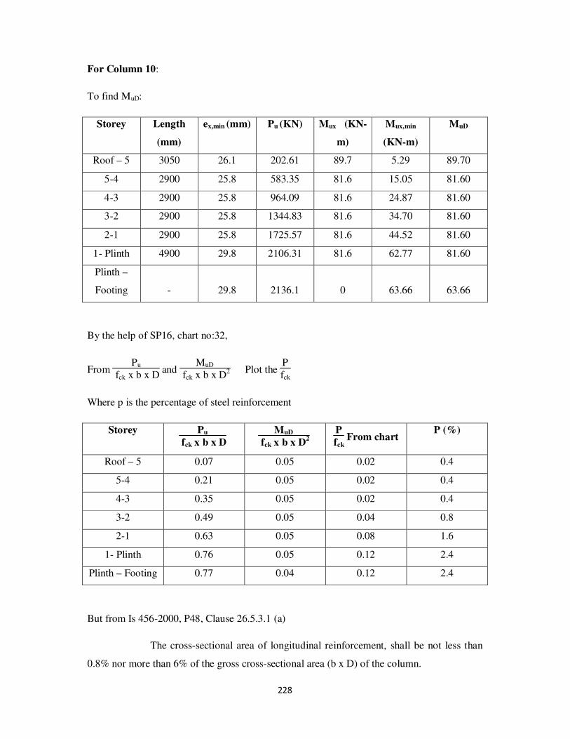
228
For Column 10:
To find MuD:
Storey Length
(mm)
ex,min (mm) Pu (KN) Mux (KN-
m)
Mux,min
(KN-m)
MuD
Roof – 5 3050 26.1 202.61 89.7 5.29 89.70
5-4 2900 25.8 583.35 81.6 15.05 81.60
4-3 2900 25.8 964.09 81.6 24.87 81.60
3-2 2900 25.8 1344.83 81.6 34.70 81.60
2-1 2900 25.8 1725.57 81.6 44.52 81.60
1- Plinth 4900 29.8 2106.31 81.6 62.77 81.60
Plinth –
Footing
-
29.8 2136.1 0 63.66 63.66
By the help of SP16, chart no:32,
From Pu
fck x b x D and
MuD
fck x b x D2 Plot the P
fck
Where p is the percentage of steel reinforcement
Storey Pu
fck x b x D
MuD
fck x b x D2
P
fck From chart
P (%)
Roof – 5 0.07 0.05 0.02 0.4
5-4 0.21 0.05 0.02 0.4
4-3 0.35 0.05 0.02 0.4
3-2 0.49 0.05 0.04 0.8
2-1 0.63 0.05 0.08 1.6
1- Plinth 0.76 0.05 0.12 2.4
Plinth – Footing 0.77 0.04 0.12 2.4
But from Is 456-2000, P48, Clause 26.5.3.1 (a)
The cross-sectional area of longitudinal reinforcement, shall be not less than
0.8% nor more than 6% of the gross cross-sectional area (b x D) of the column.

229
Therefore, provide P = 0.8%
Ast = 0.8
100 x 230 x 600 = 1104 mm
2
No. of bars of 16mmφ bars = 4 x 1104
π x (16)2 = 5.49 say 6 bars
Therefore provide 6 bars of 16mmφ bars.
For P = 1.6%
Ast = 1.6
100 x 230 x 600 = 2208 mm
2
No. of bars of 20mmφ bars = 4 x 2208
π x (20)2 = 7 bars
Therefore provide 8 bars of 20mmφ bars. (Each side 4bars)
For P = 2.4%
Ast = 2.4
100 x 230 x 600 = 3312 mm2
No. of bars of 25mmφ bars = 4 x 3312
π x (25)2 = 6.75 bars say 8 bars
Therefore provide 8 bars of 25mmφ bars.
Design of lateral ties:
1. Should not be less than 6mm
2. 1
4 x diameter of max main steel bar =
1
4 x 25 = 6.25mm say 8mm
Maximum of two values =8mm.
Design of pitch:
1. Least lateral dimension = 230mm
2. 16 x diameter of main steel bar = 16 x 16 = 256
3. 300mm

230
Minimum of the above values is considered.
Therefore, provide 8mm φ bars @230mm c/c.
No. of bars:
Storey Ast (mm2) No.of bars:
Roof-5 1104 6 bars of 16mm φ
5-4 1104 6 bars of 16mm φ
4-3 1104 6 bars of 16mm φ
3-2 1104 6 bars of 16mm φ
2-1 2208 8 bars of 20mm φ
1-Plinth 3312 8 bars of 25mm φ
Plinth – footing 3312 8 bars of 25mm φ
For Column 01:
To find MuD:
Storey Length
(mm)
ex,min (mm) Pu (KN) Mux (KN-
m)
Mux,min
(KN-m)
MuD
Roof – 5 3050 26.1 133.97 136.67 3.50 136.67
5-4 2900 25.8 383.39 122.6 9.89 122.60
4-3 2900 25.8 632.81 122.6 16.33 122.60
3-2 2900 25.8 882.23 122.6 22.76 122.60
2-1 2900 25.8 1131.65 122.6 29.20 122.60
1- Plinth 4900 29.8 1381.07 122.6 41.16 122.60
Plinth –
Footing
-
29.8 1430.66 0 42.63 42.63
By the help of SP16, chart no:32,
From Pu
fck x b x D and
MuD
fck x b x D2 Plot the
P
fck
Where p is the percentage of steel reinforcement

231
Storey Pu
fck x b x D
MuD
fck x b x D2
P
fck From chart
P (%)
Roof – 5 0.05 0.08 0.02 0.4
5-4 0.14 0.07 0.02 0.4
4-3 0.23 0.07 0.02 0.4
3-2 0.32 0.07 0.04 0.8
2-1 0.41 0.07 0.04 0.8
1- Plinth 0.50 0.07 0.06 1.2
Plinth – Footing 0.52 0.03 0.06 1.2
Provide min P = 0.8%
Ast = 0.8
100 x 230 x 600 = 1104 mm2
No. of bars of 16mmφ bars = 4 x 1104
π x (16)2 = 5.49 say 6 bars
For P=1.2%
Ast = 1.2
100 x 230 x 600 = 1656 mm
2
No. of bars of 20mmφ bars = 4 x 1656
π x (20)2 = 5.27 say 6 bars
Therefore provide 6 bars of 20mmφ bars.
Design of lateral ties:
1. Should not be less than 6mm
2. 1
4 x diameter of max main steel bar =
1
4 x 20 = 5mm
Maximum of two values =6mm.
But in the recent construction the usage of 6mm bars is outdated. Therefore consider
minimum 8mm dia bars.
Design of pitch:
1. Least lateral dimension = 230mm

232
2. 16 x diameter of main steel bar = 16 x 16 = 256
3. 300mm
Minimum of the above values is considered.
Therefore, provide 8mm φ bars @230mm c/c
No. of bars:
Storey Ast (mm2) No.of bars:
Roof-5 1104 6 bars of 16mm φ
5-4 1104 6 bars of 16mm φ
4-3 1104 6 bars of 16mm φ
3-2 1104 6 bars of 16mm φ
2-1 1104 6 bars of 16mm φ
1-Plinth 1656 6 bars of 20mm φ
Plinth – footing 1656 6 bars of 20mm φ

233
For frame 20-11-02:
Columns are C20 at left end, C12 at middle and C02 at right end of the frame.
Section: 230mm x 600mm
Cover (d’) = 50mm
Minimum eccentricity (ex,min) = unsupported length
500 +
lateral dimension
30 or
= 20mm

234
fck x b x D = 20 x 230 x 600 = 2760000N = 2760 KN
fck x b x D2 = 20 x 230 x (600)
2 = 1676 x 10
6 N-mm = 1676 KN-m
For Column 20:
To find MuD:
Storey Length
(mm)
ex,min (mm) Pu (KN) Mux (KN-
m)
Mux,min
(KN-m)
MuD
Roof – 5 2900 25.8 137.01 68.42 3.53 68.42
5-4 2750 25.5 315.59 37.77 8.05 37.77
4-3 2750 25.5 494.17 37.77 12.60 37.77
3-2 2750 25.5 672.75 37.77 17.16 37.77
2-1 2750 25.5 851.33 37.77 21.71 37.77
1- Plinth 4750 29.5 1029.91 37.77 30.38 37.77
Plinth –
Footing
-
29.5 1091.71 0 32.21 32.21
By the help of SP16, chart no: 32,
From Pu
fck x b x D and
MuD
fck x b x D2 Plot the
P
fck
Where p is the percentage of steel reinforcement
Storey Pu
fck x b x D
MuD
fck x b x D2
P
fck From chart
P (%)
Roof – 5 0.05 0.04 0.01 0.2
5-4 0.11 0.02 0.01 0.2
4-3 0.18 0.02 0.01 0.2
3-2 0.24 0.02 0.01 0.2
2-1 0.31 0.02 0.01 0.2
1- Plinth 0.37 0.02 0.01 0.2
Plinth – Footing 0.40 0.02 0.01 0.2

235
Therefore, provide P = 0.8%
Ast = 0.8
100 x 230 x 600 = 1104 mm
2
No. of bars of 16mmφ bars = 4 x 1104
π x (16)2 = 5.49 say 6 bars
Therefore provide 6 bars of 16mmφ bars.
Design of lateral ties:
1. Should not be less than 6mm
2. 1
4 x diameter of max main steel bar =
1
4 x 16 = 4mm
Maximum of two values =6mm.
But in the recent construction the usage of 6mm bars is outdated. Therefore consider
minimum 8mm dia bars.
Design of pitch:
1. Least lateral dimension = 230mm
2. 16 x diameter of main steel bar = 16 x 16 = 256
3. 300mm
Minimum of the above values is considered.
Therefore, provide 8mm φ bars @230mm c/c.
No. of bars:
Storey Ast (mm2) No.of bars:
Roof-5 1104 6 bars of 16mm φ
5-4 1104 6 bars of 16mm φ
4-3 1104 6 bars of 16mm φ
3-2 1104 6 bars of 16mm φ
2-1 1104 6 bars of 16mm φ
1-Plinth 1104 6 bars of 16mm φ
Plinth – footing 1104 6 bars of 16mm φ

236
For Column 11:
To find MuD:
Storey Length
(mm)
ex,min (mm) Pu (KN) Mux (KN-
m)
Mux,min
(KN-m)
MuD
Roof – 5 2900 25.8 279.26 93.54 7.20 93.54
5-4 2750 25.5 806.49 108.74 20.57 108.74
4-3 2750 25.5 1307.98 108.74 33.35 108.74
3-2 2750 25.5 1809.47 108.74 46.14 108.74
2-1 2750 25.5 2310.96 108.74 58.93 108.74
1- Plinth 4750 29.5 2812.45 108.74 82.97 108.74
Plinth –
Footing
- 29.5 2861.68 0 84.42 84.42
By the help of SP16, chart no: 32,
From Pu
fck x b x D and
MuD
fck x b x D2 Plot the P
fck
Where p is the percentage of steel reinforcement
Storey Pu
fck x b x D
MuD
fck x b x D2
P
fck From chart
P (%)
Roof – 5 0.10 0.06 0.02 0.4
5-4 0.29 0.07 0.02 0.4
4-3 0.47 0.07 0.06 1.2
3-2 0.66 0.07 0.1 2
2-1 0.84 0.07 0.16 3.2
1- Plinth 1.02 0.07 0.2 4
Plinth – Footing 1.04 0.05 0.2 4
For P less than 0.8, Provide P = 0.8%
Ast = 0.8
100 x 230 x 600 = 1104 mm2

237
No. of bars of 16mmφ bars = 4 x 1104
π x (16)2 = 5.49 say 6 bars
Therefore provide 6 bars of 16mmφ bars.
For P = 1.2%
Ast = 1.2
100 x 230 x 600 = 1656 mm
2
No. of bars of 20mmφ bars = 4 x 1656
π x (20)2 = 5.27, say 6 bars
Therefore provide 6 bars of 20mmφ bars.
For P = 2%
Ast = 2
100 x 230 x 600 = 2760 mm
2
No. of bars of 25mmφ bars = 4 x 2760
π x (25)2 = 5.62 bars say 6 bars
Therefore provide 6 bars of 25mmφ bars.
For P = 3.2%
Ast = 3.2
100 x 230 x 600 = 4416 mm2
No. of bars of 25mmφ bars = 4 x 4416
π x (25)2 = 9 bars
Therefore provide 10 bars of 25mmφ bars. (Each side 5bars)
For P = 4%
Ast = 4
100 x 230 x 600 = 5520 mm2
No. of bars of 25mmφ bars = 4 x 5520
π x (25)2 = 11.24 say 12 bars
Therefore provide 12 bars of 25mmφ bars.

238
Design of lateral ties:
1. Should not be less than 6mm
2. 1
4 x diameter of max main steel bar =
1
4 x 25 = 6.25mm say 8mm
Maximum of two values =8mm.
Design of pitch:
1. Least lateral dimension = 230mm
2. 16 x diameter of main steel bar = 16 x 25 = 400 mm
3. 300mm
Minimum of the above values is considered.
Therefore, provide 8mm φ bars @230mm c/c.
No. of bars:
Storey Ast (mm2) No.of bars:
Roof-5 1104 6 bars of 16mm φ
5-4 1104 6 bars of 16mm φ
4-3 1656 6 bars of 20mm φ
3-2 2760 6 bars of 25mm φ
2-1 4416 10 bars of 25mm φ
1-Plinth 5520 12 bars of 25mm φ
Plinth – footing 5520 12 bars of 25mm φ
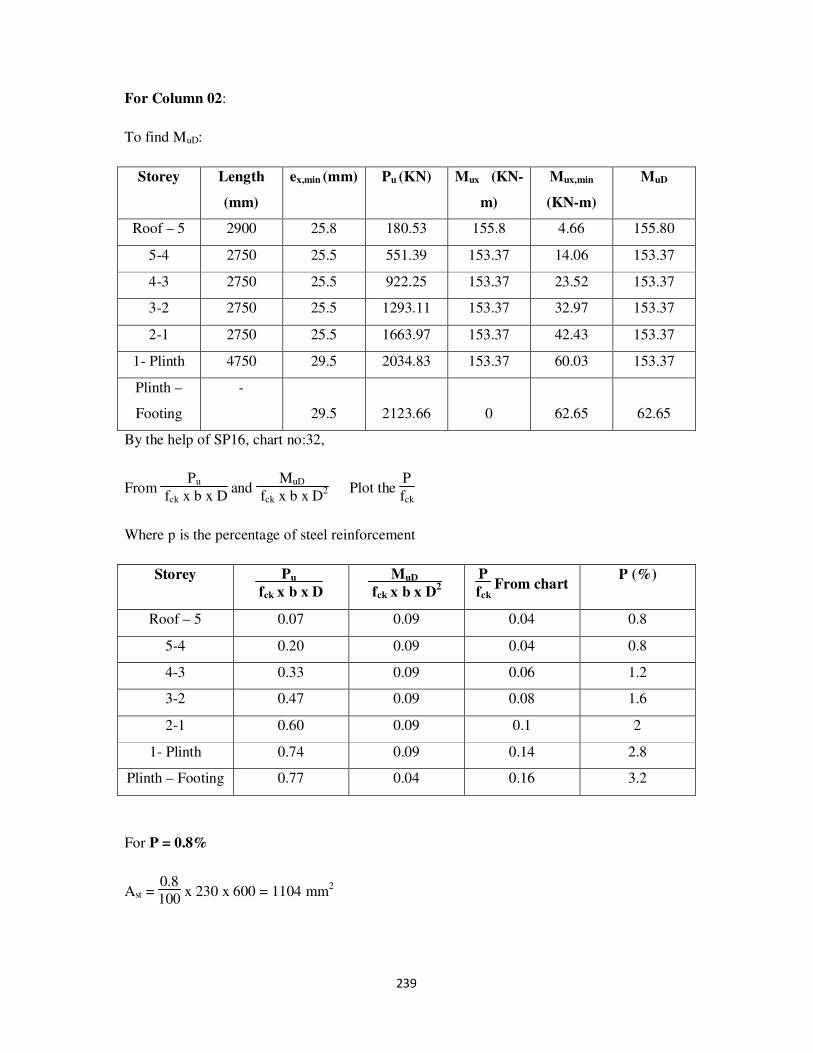
239
For Column 02:
To find MuD:
Storey Length
(mm)
ex,min (mm) Pu (KN) Mux (KN-
m)
Mux,min
(KN-m)
MuD
Roof – 5 2900 25.8 180.53 155.8 4.66 155.80
5-4 2750 25.5 551.39 153.37 14.06 153.37
4-3 2750 25.5 922.25 153.37 23.52 153.37
3-2 2750 25.5 1293.11 153.37 32.97 153.37
2-1 2750 25.5 1663.97 153.37 42.43 153.37
1- Plinth 4750 29.5 2034.83 153.37 60.03 153.37
Plinth –
Footing
-
29.5 2123.66 0 62.65 62.65
By the help of SP16, chart no:32,
From Pu
fck x b x D and
MuD
fck x b x D2 Plot the
P
fck
Where p is the percentage of steel reinforcement
Storey Pu
fck x b x D
MuD
fck x b x D2
P
fck From chart
P (%)
Roof – 5 0.07 0.09 0.04 0.8
5-4 0.20 0.09 0.04 0.8
4-3 0.33 0.09 0.06 1.2
3-2 0.47 0.09 0.08 1.6
2-1 0.60 0.09 0.1 2
1- Plinth 0.74 0.09 0.14 2.8
Plinth – Footing 0.77 0.04 0.16 3.2
For P = 0.8%
Ast = 0.8
100 x 230 x 600 = 1104 mm
2

240
No. of bars of 16mmφ bars = 4 x 1104
π x (16)2 = 5.49 say 6 bars
Therefore provide 6 bars of 16mmφ bars.
For P=1.2%
Ast = 1.2
100 x 230 x 600 = 1656 mm
2
No. of bars of 20mmφ bars = 4 x 1656
π x (20)2 = 5.27 say 6 bars
Therefore provide 6 bars of 20mmφ bars.
For P=1.6%
Ast = 1.6
100 x 230 x 600 = 2208 mm
2
No. of bars of 25mmφ bars = 4 x 2208
π x (25)2 = 4.5 say 6 bars
Therefore provide 6 bars of 25mmφ bars.
For P = 2%
Ast = 2
100 x 230 x 600 = 2760 mm2
No. of bars of 25mmφ bars = 4 x 2760
π x (25)2 = 5.62 bars say 6 bars
Therefore provide 6 bars of 25mmφ bars.
For P = 2.8%
Ast = 2.8
100 x 230 x 600 = 3864 mm2
No. of bars of 25mmφ bars = 4 x 3864
π x (25)2 = 7.87 bars say 8 bars
Therefore provide 8 bars of 25mmφ bars.

241
For P = 3.2%
Ast = 3.2
100 x 230 x 600 = 4416 mm
2
No. of bars of 25mmφ bars = 4 x 4416
π x (25)2 = 9 bars
Therefore provide 10 bars of 25mmφ bars. (Each side 5bars)
Design of lateral ties:
1. Should not be less than 6mm
2. 1
4 x diameter of max main steel bar =
1
4 x 25 = 6.25mm say 8mm
Maximum of two values =8mm.
Design of pitch:
1. Least lateral dimension = 230mm
2. 16 x diameter of main steel bar = 16 x 25 = 400mm
3. 300mm
Minimum of the above values is considered.
Therefore, provide 8mm φ bars @230mm c/c.
No. of bars:
Storey Ast (mm2) No.of bars:
Roof-5 1104 6 bars of 16mm φ
5-4 1104 6 bars of 16mm φ
4-3 1656 6 bars of 20mm φ
3-2 2208 6 bars of 25mm φ
2-1 2760 6 bars of 25mm φ
1-Plinth 3864 8 bars of 25mm φ
Plinth – footing 4416 10 bars of 25mm φ
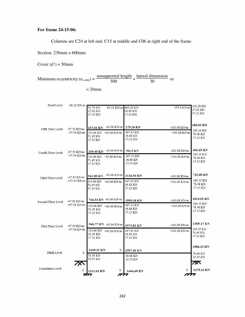
242
For frame 24-15-06:
Columns are C24 at left end, C15 at middle and C06 at right end of the frame.
Section: 230mm x 600mm
Cover (d’) = 50mm
Minimum eccentricity (ex,min) = unsupported length
500 +
lateral dimension
30 or
= 20mm

243
fck x b x D = 20 x 230 x 600 = 2760000N = 2760 KN
fck x b x D2 = 20 x 230 x (600)
2 = 1676 x 10
6 N-mm = 1676 KN-m
For Column 24:
To find MuD:
Storey Length
(mm)
ex,min (mm) Pu (KN) Mux (KN-
m)
Mux,min
(KN-m)
MuD
Roof – 5 2900 25.8 137.01 68.42 3.53 68.42
5-4 2750 25.5 339.45 47.54 8.66 47.54
4-3 2750 25.5 541.89 47.54 13.82 47.54
3-2 2750 25.5 744.33 47.54 18.98 47.54
2-1 2750 25.5 946.77 47.54 24.14 47.54
1- Plinth 4750 29.5 1149.21 47.54 33.90 47.54
Plinth –
Footing
-
29.5 1211.01 0 35.72 35.72
By the help of SP16, chart no: 32,
From Pu
fck x b x D and
MuD
fck x b x D2 Plot the
P
fck
Where p is the percentage of steel reinforcement
Storey Pu
fck x b x D
MuD
fck x b x D2
P
fck From chart
P (%)
Roof – 5 0.05 0.04 0.01 0.2
5-4 0.12 0.03 0.01 0.2
4-3 0.20 0.03 0.01 0.2
3-2 0.27 0.03 0.01 0.2
2-1 0.34 0.03 0.01 0.2
1- Plinth 0.42 0.03 0.01 0.2
Plinth – Footing 0.44 0.02 0.01 0.2

244
Therefore, provide P = 0.8%
Ast = 0.8
100 x 230 x 600 = 1104 mm
2
No. of bars of 16mmφ bars = 4 x 1104
π x (16)2 = 5.49 say 6 bars
Therefore provide 6 bars of 16mmφ bars.
Design of lateral ties:
1. Should not be less than 6mm
2. 1
4 x diameter of max main steel bar =
1
4 x 16 = 4mm
Maximum of two values =6mm.
But in the recent construction the usage of 6mm bars is outdated. Therefore consider
minimum 8mm dia bars.
Design of pitch:
1. Least lateral dimension = 230mm
2. 16 x diameter of main steel bar = 16 x 16 = 256
3. 300mm
Minimum of the above values is considered.
Therefore, provide 8mm φ bars @230mm c/c.
No. of bars:
Storey Ast (mm2) No.of bars:
Roof-5 1104 6 bars of 16mm φ
5-4 1104 6 bars of 16mm φ
4-3 1104 6 bars of 16mm φ
3-2 1104 6 bars of 16mm φ
2-1 1104 6 bars of 16mm φ
1-Plinth 1104 6 bars of 16mm φ
Plinth – footing 1104 6 bars of 16mm φ

245
For Column 15:
To find MuD:
Storey Length
(mm)
ex,min (mm) Pu (KN) Mux (KN-
m)
Mux,min
(KN-m)
MuD
Roof – 5 2900 25.8 279.26 93.54 7.20 93.54
5-4 2750 25.5 702.9 63.86 17.92 63.86
4-3 2750 25.5 1126.54 63.86 28.73 63.86
3-2 2750 25.5 1550.18 63.86 39.53 63.86
2-1 2750 25.5 1973.82 63.86 50.33 63.86
1- Plinth 4750 29.5 2397.46 63.86 70.73 70.73
Plinth –
Footing
- 29.5 2446.69 0 72.18 72.18
By the help of SP16, chart no: 32,
From Pu
fck x b x D and
MuD
fck x b x D2 Plot the P
fck
Where p is the percentage of steel reinforcement
Storey Pu
fck x b x D
MuD
fck x b x D2
P
fck From chart
P (%)
Roof – 5 0.10 0.06 0.01 0.2
5-4 0.25 0.04 0.01 0.2
4-3 0.41 0.04 0.02 0.4
3-2 0.56 0.04 0.06 1.2
2-1 0.72 0.04 0.1 2
1- Plinth 0.87 0.04 0.16 3.2
Plinth – Footing 0.89 0.04 0.16 3.2
For P less than 0.8, Provide P = 0.8%
Ast = 0.8
100 x 230 x 600 = 1104 mm2
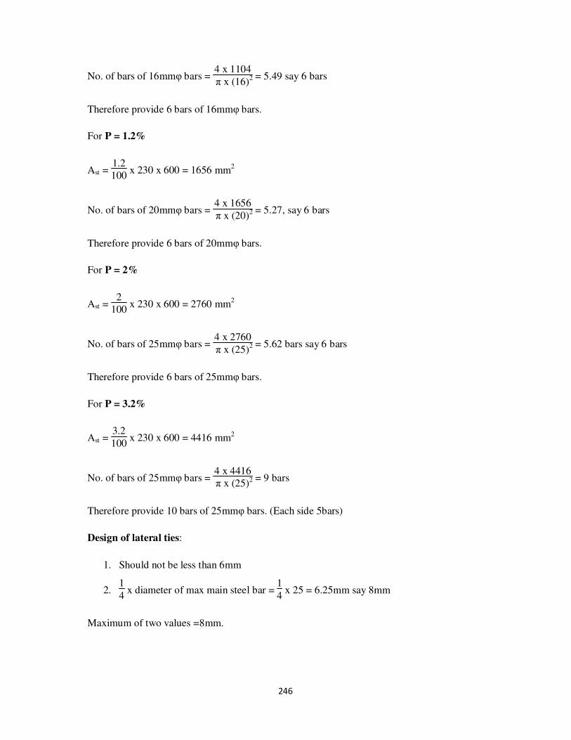
246
No. of bars of 16mmφ bars = 4 x 1104
π x (16)2 = 5.49 say 6 bars
Therefore provide 6 bars of 16mmφ bars.
For P = 1.2%
Ast = 1.2
100 x 230 x 600 = 1656 mm
2
No. of bars of 20mmφ bars = 4 x 1656
π x (20)2 = 5.27, say 6 bars
Therefore provide 6 bars of 20mmφ bars.
For P = 2%
Ast = 2
100 x 230 x 600 = 2760 mm
2
No. of bars of 25mmφ bars = 4 x 2760
π x (25)2 = 5.62 bars say 6 bars
Therefore provide 6 bars of 25mmφ bars.
For P = 3.2%
Ast = 3.2
100 x 230 x 600 = 4416 mm2
No. of bars of 25mmφ bars = 4 x 4416
π x (25)2 = 9 bars
Therefore provide 10 bars of 25mmφ bars. (Each side 5bars)
Design of lateral ties:
1. Should not be less than 6mm
2. 1
4 x diameter of max main steel bar =
1
4 x 25 = 6.25mm say 8mm
Maximum of two values =8mm.

247
Design of pitch:
1. Least lateral dimension = 230mm
2. 16 x diameter of main steel bar = 16 x 25 = 400 mm
3. 300mm
Minimum of the above values is considered.
Therefore, provide 8mm φ bars @230mm c/c.
No. of bars:
Storey Ast (mm2) No.of bars:
Roof-5 1104 6 bars of 16mm φ
5-4 1104 6 bars of 16mm φ
4-3 1104 6 bars of 16mm φ
3-2 1656 6 bars of 20mm φ
2-1 2760 6 bars of 25mm φ
1-Plinth 4416 10 bars of 25mm φ
Plinth – footing 4416 10 bars of 25mm φ
For Column 06:
To find MuD:
Storey Length
(mm)
ex,min (mm) Pu (KN) Mux (KN-
m)
Mux,min
(KN-m)
MuD
Roof – 5 2900 25.8 180.53 155.8 4.66 155.80
5-4 2750 25.5 461.69 103.08 11.77 103.08
4-3 2750 25.5 742.85 103.08 18.94 103.08
3-2 2750 25.5 1024.01 103.08 26.11 103.08
2-1 2750 25.5 1305.17 103.08 33.28 103.08
1- Plinth 4750 29.5 1586.33 103.08 46.80 103.08
Plinth –
Footing
-
29.5 1675.16 0 49.42 49.42
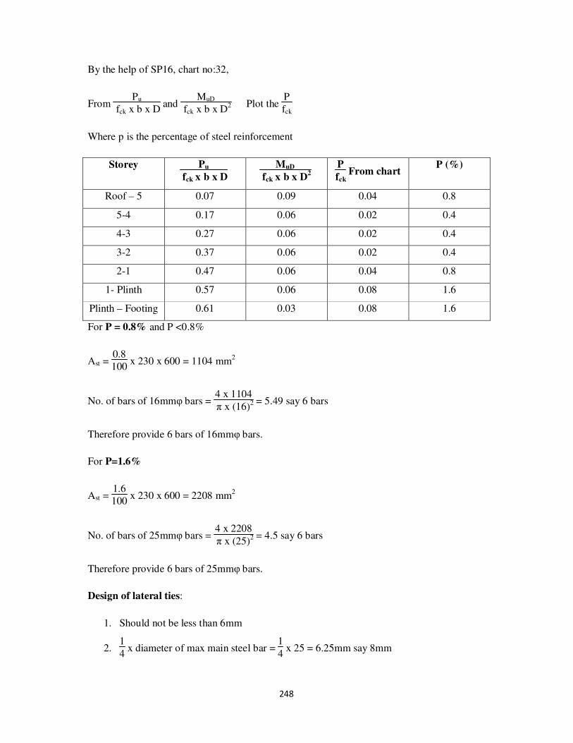
248
By the help of SP16, chart no:32,
From Pu
fck x b x D and
MuD
fck x b x D2 Plot the
P
fck
Where p is the percentage of steel reinforcement
Storey Pu
fck x b x D
MuD
fck x b x D2
P
fck From chart
P (%)
Roof – 5 0.07 0.09 0.04 0.8
5-4 0.17 0.06 0.02 0.4
4-3 0.27 0.06 0.02 0.4
3-2 0.37 0.06 0.02 0.4
2-1 0.47 0.06 0.04 0.8
1- Plinth 0.57 0.06 0.08 1.6
Plinth – Footing 0.61 0.03 0.08 1.6
For P = 0.8% and P <0.8%
Ast = 0.8
100 x 230 x 600 = 1104 mm
2
No. of bars of 16mmφ bars = 4 x 1104
π x (16)2 = 5.49 say 6 bars
Therefore provide 6 bars of 16mmφ bars.
For P=1.6%
Ast = 1.6
100 x 230 x 600 = 2208 mm
2
No. of bars of 25mmφ bars = 4 x 2208
π x (25)2 = 4.5 say 6 bars
Therefore provide 6 bars of 25mmφ bars.
Design of lateral ties:
1. Should not be less than 6mm
2. 1
4 x diameter of max main steel bar =
1
4 x 25 = 6.25mm say 8mm
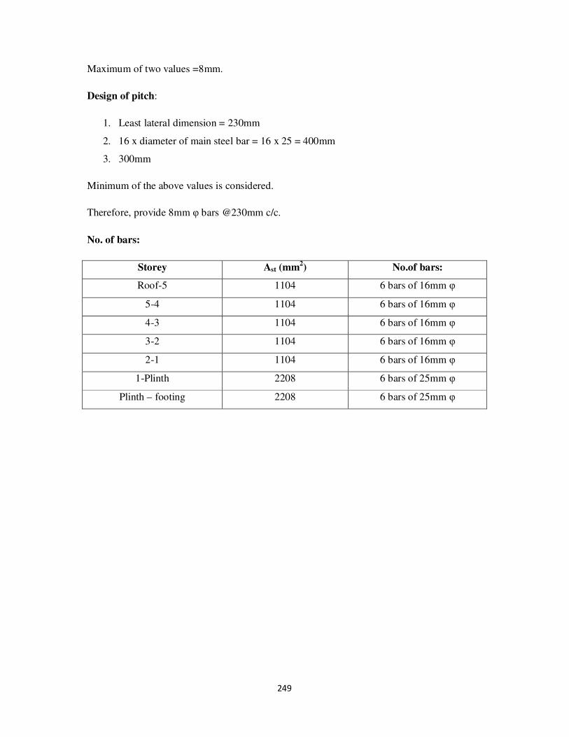
249
Maximum of two values =8mm.
Design of pitch:
1. Least lateral dimension = 230mm
2. 16 x diameter of main steel bar = 16 x 25 = 400mm
3. 300mm
Minimum of the above values is considered.
Therefore, provide 8mm φ bars @230mm c/c.
No. of bars:
Storey Ast (mm2) No.of bars:
Roof-5 1104 6 bars of 16mm φ
5-4 1104 6 bars of 16mm φ
4-3 1104 6 bars of 16mm φ
3-2 1104 6 bars of 16mm φ
2-1 1104 6 bars of 16mm φ
1-Plinth 2208 6 bars of 25mm φ
Plinth – footing 2208 6 bars of 25mm φ

250
For frame 25-16-07:
Columns are C25 at left end, C16 at middle and C07 at right end of the frame.
Section: 230mm x 600mm
Cover (d’) = 50mm
Minimum eccentricity (ex,min) = unsupported length
500 +
lateral dimension
30 or
= 20mm

251
fck x b x D = 20 x 230 x 600 = 2760000N = 2760 KN
fck x b x D2 = 20 x 230 x (600)
2 = 1676 x 10
6 N-mm = 1676 KN-m
For Column 25:
To find MuD:
Storey Length
(mm)
ex,min (mm) Pu (KN) Mux (KN-
m)
Mux,min
(KN-m)
MuD
Roof – 5 2900 25.8 137.01 68.42 3.53 68.42
5-4 2750 25.5 326.68 42.84 8.33 42.84
4-3 2750 25.5 516.35 42.84 13.17 42.84
3-2 2750 25.5 706.02 42.84 18.00 42.84
2-1 2750 25.5 895.69 42.84 22.84 42.84
1- Plinth 4750 29.5 1085.36 42.84 32.02 42.84
Plinth –
Footing
-
29.5 1147.16 0 33.84 33.84
By the help of SP16, chart no:32,
From Pu
fck x b x D and
MuD
fck x b x D2 Plot the
P
fck
Where p is the percentage of steel reinforcement
Storey Pu
fck x b x D
MuD
fck x b x D2
P
fck From chart
P (%)
Roof – 5 0.05 0.04 0.01 0.2
5-4 0.12 0.03 0.01 0.2
4-3 0.19 0.03 0.01 0.2
3-2 0.26 0.03 0.01 0.2
2-1 0.32 0.03 0.01 0.2
1- Plinth 0.39 0.03 0.02 0.4
Plinth – Footing 0.42 0.02 0.02 0.4

252
For P < 0.8%, Provide P = 0.8%
Ast = 0.8
100 x 230 x 600 = 1104 mm
2
No. of bars of 16mmφ bars = 4 x 1104
π x (16)2 = 5.49 say 6 bars
Therefore provide 6 bars of 16mmφ bars.
Design of lateral ties:
1. Should not be less than 6mm
2. 1
4 x diameter of max main steel bar =
1
4 x 16 = 4mm
Maximum of two values =6mm.
But in the recent construction the usage of 6mm bars is outdated. Therefore consider
minimum 8mm dia bars.
Design of pitch:
1. Least lateral dimension = 230mm
2. 16 x diameter of main steel bar = 16 x 16 = 256
3. 300mm
Minimum of the above values is considered.
Therefore, provide 8mm φ bars @230mm c/c.
No. of bars:
Storey Ast (mm2) No.of bars:
Roof-5 1104 6 bars of 16mm φ
5-4 1104 6 bars of 16mm φ
4-3 1104 6 bars of 16mm φ
3-2 1104 6 bars of 16mm φ
2-1 1104 6 bars of 16mm φ
1-Plinth 1104 6 bars of 16mm φ
Plinth – footing 1104 6 bars of 16mm φ

253
For Column 16:
To find MuD:
Storey Length
(mm)
ex,min (mm) Pu (KN) Mux (KN-
m)
Mux,min
(KN-m)
MuD
Roof – 5 2900 25.8 279.26 68.42 7.20 68.42
5-4 2750 25.5 744.68 42.84 18.99 42.84
4-3 2750 25.5 1210.1 42.84 30.86 42.84
3-2 2750 25.5 1675.52 42.84 42.73 42.84
2-1 2750 25.5 2140.94 42.84 54.59 54.59
1- Plinth 4750 29.5 2606.36 42.84 76.89 76.89
Plinth –
Footing
- 29.5 2655.59 0 78.34 78.34
By the help of SP16, chart no: 32,
From Pu
fck x b x D and
MuD
fck x b x D2 Plot the P
fck
Where p is the percentage of steel reinforcement
Storey Pu
fck x b x D
MuD
fck x b x D2
P
fck From chart
P (%)
Roof – 5 0.10 0.04 0.01 0.2
5-4 0.27 0.03 0.01 0.2
4-3 0.44 0.03 0.02 0.4
3-2 0.61 0.03 0.08 1.6
2-1 0.78 0.03 0.12 2.4
1- Plinth 0.94 0.05 0.18 3.6
Plinth – Footing 0.96 0.05 0.18 3.6
For P less than 0.8, Provide P = 0.8%
Ast = 0.8
100 x 230 x 600 = 1104 mm2

254
No. of bars of 16mmφ bars = 4 x 1104
π x (16)2 = 5.49 say 6 bars
Therefore provide 6 bars of 16mmφ bars.
For P = 1.6%
Ast = 1.6
100 x 230 x 600 = 2208 mm
2
No. of bars of 25mmφ bars = 4 x 2208
π x (20)2 = 4.5 say 6 bars
Therefore provide 6 bars of 25mmφ bars.
For P = 2.4%
Ast = 2.4
100 x 230 x 600 = 3312 mm
2
No. of bars of 25mmφ bars = 4 x 3312
π x (25)2 = 6.77 bars say 8 bars
Therefore provide 8 bars of 25mmφ bars.
For P = 3.6%
Ast = 3.6
100 x 230 x 600 = 4968 mm2
No. of bars of 25mmφ bars = 4 x 4968
π x (25)2 = 10.12, say 12 bars
Therefore provide 12 bars of 25mmφ bars.
Design of lateral ties:
1. Should not be less than 6mm
2. 1
4 x diameter of max main steel bar =
1
4 x 25 = 6.25mm say 8mm
Maximum of two values =8mm.

255
Design of pitch:
1. Least lateral dimension = 230mm
2. 16 x diameter of main steel bar = 16 x 25 = 400 mm
3. 300mm
Minimum of the above values is considered.
Therefore, provide 8mm φ bars @230mm c/c.
No. of bars:
Storey Ast (mm2) No.of bars:
Roof-5 1104 6 bars of 16mm φ
5-4 1104 6 bars of 16mm φ
4-3 1104 6 bars of 16mm φ
3-2 2208 6 bars of 25mm φ
2-1 3312 8 bars of 25mm φ
1-Plinth 4968 12 bars of 25mm φ
Plinth – footing 4968 12 bars of 25mm φ
For Column 07:
To find MuD:
Storey Length
(mm)
ex,min (mm) Pu (KN) Mux (KN-
m)
Mux,min
(KN-m)
MuD
Roof – 5 2900 25.8 180.53 155.8 4.66 155.80
5-4 2750 25.5 511.2 130.75 13.04 130.75
4-3 2750 25.5 841.87 130.75 21.47 130.75
3-2 2750 25.5 1172.54 130.75 29.90 130.75
2-1 2750 25.5 1503.21 130.75 38.33 130.75
1- Plinth 4750 29.5 1833.88 130.75 54.10 130.75
Plinth –
Footing
-
29.5 1922.71 0 56.72 56.72

256
By the help of SP16, chart no:32,
From Pu
fck x b x D and
MuD
fck x b x D2 Plot the
P
fck
Where p is the percentage of steel reinforcement
Storey Pu
fck x b x D
MuD
fck x b x D2
P
fck From chart
P (%)
Roof – 5 0.07 0.09 0.04 0.8
5-4 0.19 0.08 0.02 0.4
4-3 0.31 0.08 0.04 0.8
3-2 0.42 0.08 0.06 1.2
2-1 0.54 0.08 0.08 1.6
1- Plinth 0.66 0.08 0.12 2.4
Plinth – Footing 0.70 0.03 0.12 2.4
For P < 0.8%, Provide P = 0.8%
Ast = 0.8
100 x 230 x 600 = 1104 mm
2
No. of bars of 16mmφ bars = 4 x 1104
π x (16)2 = 5.49 say 6 bars
Therefore provide 6 bars of 16mmφ bars.
For P=1.2%
Ast = 1.2
100 x 230 x 600 = 1656 mm
2
No. of bars of 20mmφ bars = 4 x 1656
π x (20)2 = 5.27 say 6 bars
Therefore provide 6 bars of 20mmφ bars.
For P=1.6%
Ast = 1.6
100 x 230 x 600 = 2208 mm
2
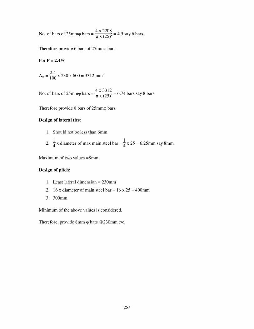
257
No. of bars of 25mmφ bars = 4 x 2208
π x (25)2 = 4.5 say 6 bars
Therefore provide 6 bars of 25mmφ bars.
For P = 2.4%
Ast = 2.4
100 x 230 x 600 = 3312 mm
2
No. of bars of 25mmφ bars = 4 x 3312
π x (25)2 = 6.74 bars say 8 bars
Therefore provide 8 bars of 25mmφ bars.
Design of lateral ties:
1. Should not be less than 6mm
2. 1
4 x diameter of max main steel bar =
1
4 x 25 = 6.25mm say 8mm
Maximum of two values =8mm.
Design of pitch:
1. Least lateral dimension = 230mm
2. 16 x diameter of main steel bar = 16 x 25 = 400mm
3. 300mm
Minimum of the above values is considered.
Therefore, provide 8mm φ bars @230mm c/c.
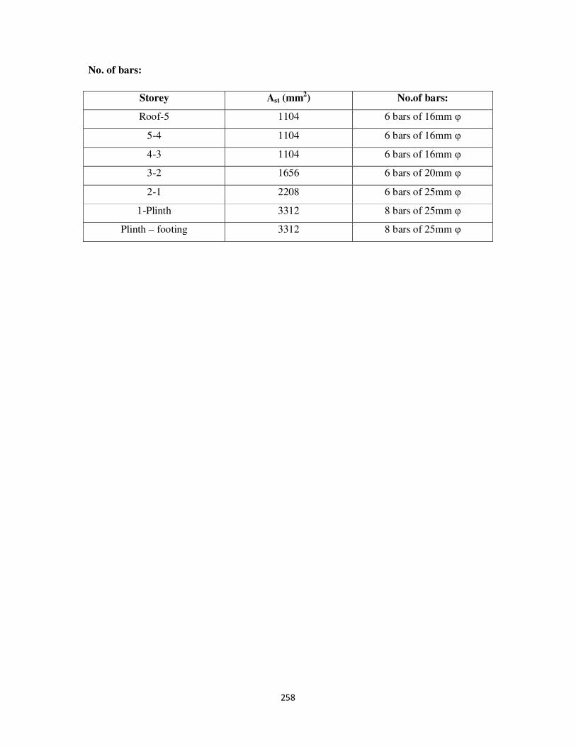
258
No. of bars:
Storey Ast (mm2) No.of bars:
Roof-5 1104 6 bars of 16mm φ
5-4 1104 6 bars of 16mm φ
4-3 1104 6 bars of 16mm φ
3-2 1656 6 bars of 20mm φ
2-1 2208 6 bars of 25mm φ
1-Plinth 3312 8 bars of 25mm φ
Plinth – footing 3312 8 bars of 25mm φ

259
For frame 26-17-08:
Columns are C26 at left end, C17 at middle and C08 at right end of the frame.
Section: 230mm x 600mm
Cover (d’) = 50mm
Minimum eccentricity (ex,min) = unsupported length
500 +
lateral dimension
30 or
= 20mm

260
fck x b x D = 20 x 230 x 600 = 2760000N = 2760 KN
fck x b x D2 = 20 x 230 x (600)
2 = 1676 x 10
6 N-mm = 1676 KN-m
For Column 26:
To find MuD:
Storey Length
(mm)
ex,min (mm) Pu (KN) Mux (KN-
m)
Mux,min
(KN-m)
MuD
Roof – 5 2900 25.8 137.01 68.42 3.53 68.42
5-4 2750 25.5 306.92 36.55 7.83 36.55
4-3 2750 25.5 476.83 36.55 12.16 36.55
3-2 2750 25.5 646.74 36.55 16.49 36.55
2-1 2750 25.5 816.65 36.55 20.82 36.55
1- Plinth 4750 29.5 986.56 36.55 29.10 36.55
Plinth –
Footing
-
29.5 1048.36 0 30.93 30.93
By the help of SP16, chart no: 32,
From Pu
fck x b x D and
MuD
fck x b x D2 Plot the
P
fck
Where p is the percentage of steel reinforcement
Storey Pu
fck x b x D
MuD
fck x b x D2
P
fck From chart
P (%)
Roof – 5 0.05 0.04 0.01 0.2
5-4 0.11 0.02 0.01 0.2
4-3 0.17 0.02 0.01 0.2
3-2 0.23 0.02 0.01 0.2
2-1 0.30 0.02 0.01 0.2
1- Plinth 0.36 0.02 0.01 0.2
Plinth – Footing 0.38 0.02 0.01 0.2

261
For P < 0.8%, provide P = 0.8%
Ast = 0.8
100 x 230 x 600 = 1104 mm
2
No. of bars of 16mmφ bars = 4 x 1104
π x (16)2 = 5.49 say 6 bars
Therefore provide 6 bars of 16mmφ bars.
Design of lateral ties:
1. Should not be less than 6mm
2. 1
4 x diameter of max main steel bar =
1
4 x 16 = 4mm
Maximum of two values =6mm.
But in the recent construction the usage of 6mm bars is outdated. Therefore consider
minimum 8mm dia bars.
Design of pitch:
1. Least lateral dimension = 230mm
2. 16 x diameter of main steel bar = 16 x 16 = 256
3. 300mm
Minimum of the above values is considered.
Therefore, provide 8mm φ bars @230mm c/c.
No. of bars:
Storey Ast (mm2) No.of bars:
Roof-5 1104 6 bars of 16mm φ
5-4 1104 6 bars of 16mm φ
4-3 1104 6 bars of 16mm φ
3-2 1104 6 bars of 16mm φ
2-1 1104 6 bars of 16mm φ
1-Plinth 1104 6 bars of 16mm φ
Plinth – footing 1104 6 bars of 16mm φ

262
For Column 17:
To find MuD:
Storey Length
(mm)
ex,min (mm) Pu (KN) Mux (KN-
m)
Mux,min
(KN-m)
MuD
Roof – 5 2900 25.8 279.26 68.42 7.20 68.42
5-4 2750 25.5 685.14 36.55 17.47 36.55
4-3 2750 25.5 1091.02 36.55 27.82 36.55
3-2 2750 25.5 1496.9 36.55 38.17 38.17
2-1 2750 25.5 1902.78 36.55 48.52 48.52
1- Plinth 4750 29.5 2308.66 36.55 68.11 68.11
Plinth –
Footing
- 29.5 2357.89 0 69.56 69.56
By the help of SP16, chart no: 32,
From Pu
fck x b x D and
MuD
fck x b x D2 Plot the P
fck
Where p is the percentage of steel reinforcement
Storey Pu
fck x b x D
MuD
fck x b x D2
P
fck From chart
P (%)
Roof – 5 0.10 0.04 0.01 0.2
5-4 0.25 0.02 0.01 0.2
4-3 0.40 0.02 0.01 0.2
3-2 0.54 0.02 0.04 0.8
2-1 0.69 0.03 0.1 2
1- Plinth 0.84 0.04 0.14 2.8
Plinth – Footing 0.85 0.04 0.14 2.8
For P less than 0.8, Provide P = 0.8%
Ast = 0.8
100 x 230 x 600 = 1104 mm2
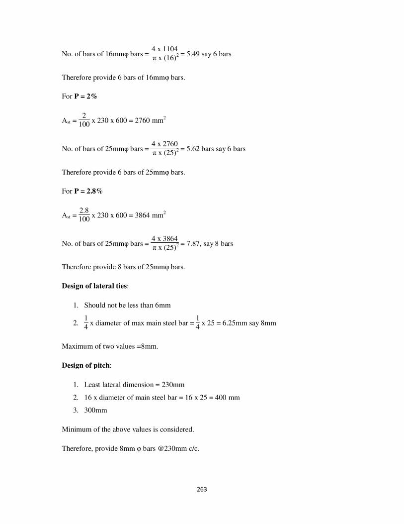
263
No. of bars of 16mmφ bars = 4 x 1104
π x (16)2 = 5.49 say 6 bars
Therefore provide 6 bars of 16mmφ bars.
For P = 2%
Ast = 2
100 x 230 x 600 = 2760 mm
2
No. of bars of 25mmφ bars = 4 x 2760
π x (25)2 = 5.62 bars say 6 bars
Therefore provide 6 bars of 25mmφ bars.
For P = 2.8%
Ast = 2.8
100 x 230 x 600 = 3864 mm
2
No. of bars of 25mmφ bars = 4 x 3864
π x (25)2 = 7.87, say 8 bars
Therefore provide 8 bars of 25mmφ bars.
Design of lateral ties:
1. Should not be less than 6mm
2. 1
4 x diameter of max main steel bar =
1
4 x 25 = 6.25mm say 8mm
Maximum of two values =8mm.
Design of pitch:
1. Least lateral dimension = 230mm
2. 16 x diameter of main steel bar = 16 x 25 = 400 mm
3. 300mm
Minimum of the above values is considered.
Therefore, provide 8mm φ bars @230mm c/c.
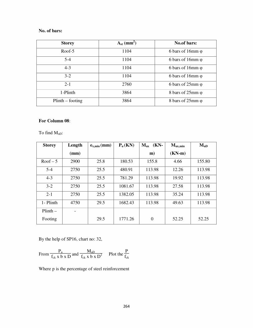
264
No. of bars:
Storey Ast (mm2) No.of bars:
Roof-5 1104 6 bars of 16mm φ
5-4 1104 6 bars of 16mm φ
4-3 1104 6 bars of 16mm φ
3-2 1104 6 bars of 16mm φ
2-1 2760 6 bars of 25mm φ
1-Plinth 3864 8 bars of 25mm φ
Plinth – footing 3864 8 bars of 25mm φ
For Column 08:
To find MuD:
Storey Length
(mm)
ex,min (mm) Pu (KN) Mux (KN-
m)
Mux,min
(KN-m)
MuD
Roof – 5 2900 25.8 180.53 155.8 4.66 155.80
5-4 2750 25.5 480.91 113.98 12.26 113.98
4-3 2750 25.5 781.29 113.98 19.92 113.98
3-2 2750 25.5 1081.67 113.98 27.58 113.98
2-1 2750 25.5 1382.05 113.98 35.24 113.98
1- Plinth 4750 29.5 1682.43 113.98 49.63 113.98
Plinth –
Footing
-
29.5 1771.26 0 52.25 52.25
By the help of SP16, chart no: 32,
From Pu
fck x b x D and
MuD
fck x b x D2 Plot the P
fck
Where p is the percentage of steel reinforcement

265
Storey Pu
fck x b x D
MuD
fck x b x D2
P
fck From chart
P (%)
Roof – 5 0.07 0.09 0.04 0.8
5-4 0.17 0.07 0.02 0.4
4-3 0.28 0.07 0.02 0.4
3-2 0.39 0.07 0.04 0.8
2-1 0.50 0.07 0.06 1.2
1- Plinth 0.61 0.07 0.1 2
Plinth – Footing 0.64 0.03 0.1 2
For P = 0.8%
Ast = 0.8
100 x 230 x 600 = 1104 mm2
No. of bars of 16mmφ bars = 4 x 1104
π x (16)2 = 5.49 say 6 bars
Therefore provide 6 bars of 16mmφ bars.
For P=1.2%
Ast = 1.2
100 x 230 x 600 = 1656 mm2
No. of bars of 20mmφ bars = 4 x 1656
π x (20)2 = 5.27 say 6 bars
Therefore provide 6 bars of 20mmφ bars.
For P = 2%
Ast = 2
100 x 230 x 600 = 2760 mm2
No. of bars of 25mmφ bars = 4 x 2760
π x (25)2 = 5.62 bars say 6 bars
Therefore provide 6 bars of 25mmφ bars.
Design of lateral ties:
1. Should not be less than 6mm

266
2. 1
4 x diameter of max main steel bar =
1
4 x 25 = 6.25mm say 8mm
Maximum of two values =8mm.
Design of pitch:
1. Least lateral dimension = 230mm
2. 16 x diameter of main steel bar = 16 x 25 = 400mm
3. 300mm
Minimum of the above values is considered.
Therefore, provide 8mm φ bars @230mm c/c.
No. of bars:
Storey Ast (mm2) No.of bars:
Roof-5 1104 6 bars of 16mm φ
5-4 1104 6 bars of 16mm φ
4-3 1104 6 bars of 16mm φ
3-2 1104 6 bars of 16mm φ
2-1 1656 6 bars of 20mm φ
1-Plinth 2760 6 bars of 25mm φ
Plinth – footing 2760 6 bars of 25mm φ

267
For frame 27-18-09:
Columns are C27 at left end, C18 at middle and C09 at right end of the frame.
Section: 230mm x 600mm
Cover (d’) = 50mm
Minimum eccentricity (ex,min) = unsupported length
500 +
lateral dimension
30 or
= 20mm
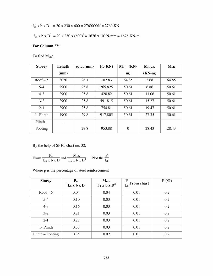
268
fck x b x D = 20 x 230 x 600 = 2760000N = 2760 KN
fck x b x D2 = 20 x 230 x (600)
2 = 1676 x 10
6 N-mm = 1676 KN-m
For Column 27:
To find MuD:
Storey Length
(mm)
ex,min (mm) Pu (KN) Mux (KN-
m)
Mux,min
(KN-m)
MuD
Roof – 5 3050 26.1 102.83 64.85 2.68 64.85
5-4 2900 25.8 265.825 50.61 6.86 50.61
4-3 2900 25.8 428.82 50.61 11.06 50.61
3-2 2900 25.8 591.815 50.61 15.27 50.61
2-1 2900 25.8 754.81 50.61 19.47 50.61
1- Plinth 4900 29.8 917.805 50.61 27.35 50.61
Plinth –
Footing
-
29.8 953.88 0 28.43 28.43
By the help of SP16, chart no: 32,
From Pu
fck x b x D and
MuD
fck x b x D2 Plot the
P
fck
Where p is the percentage of steel reinforcement
Storey Pu
fck x b x D
MuD
fck x b x D2
P
fck From chart
P (%)
Roof – 5 0.04 0.04 0.01 0.2
5-4 0.10 0.03 0.01 0.2
4-3 0.16 0.03 0.01 0.2
3-2 0.21 0.03 0.01 0.2
2-1 0.27 0.03 0.01 0.2
1- Plinth 0.33 0.03 0.01 0.2
Plinth – Footing 0.35 0.02 0.01 0.2

269
For P < 0.8, provide P = 0.8%
Ast = 0.8
100 x 230 x 600 = 1104 mm
2
No. of bars of 16mmφ bars = 4 x 1104
π x (16)2 = 5.49 say 6 bars
Therefore provide 6 bars of 16mmφ bars.
Design of lateral ties:
1. Should not be less than 6mm
2. 1
4 x diameter of max main steel bar =
1
4 x 16 = 4mm
Maximum of two values =6mm.
But in the recent construction the usage of 6mm bars is outdated. Therefore consider
minimum 8mm dia bars.
Design of pitch:
1. Least lateral dimension = 230mm
2. 16 x diameter of main steel bar = 16 x 16 = 256
3. 300mm
Minimum of the above values is considered.
Therefore, provide 8mm φ bars @230mm c/c.
No. of bars:
Storey Ast (mm2) No.of bars:
Roof-5 1104 6 bars of 16mm φ
5-4 1104 6 bars of 16mm φ
4-3 1104 6 bars of 16mm φ
3-2 1104 6 bars of 16mm φ
2-1 1104 6 bars of 16mm φ
1-Plinth 1104 6 bars of 16mm φ
Plinth – footing 1104 6 bars of 16mm φ

270
For Column 18:
To find MuD:
Storey Length
(mm)
ex,min (mm) Pu (KN) Mux (KN-
m)
Mux,min
(KN-m)
MuD
Roof – 5 3050 26.1 202.61 89.7 5.29 89.70
5-4 2900 25.8 586.58 86.44 15.13 86.44
4-3 2900 25.8 970.55 86.44 25.04 86.44
3-2 2900 25.8 1354.52 86.44 34.95 86.44
2-1 2900 25.8 1738.49 86.44 44.85 86.44
1- Plinth 4900 29.8 2122.46 86.44 63.25 86.44
Plinth –
Footing
- 29.8 2152.25 0 64.14 64.14
By the help of SP16, chart no: 32,
From Pu
fck x b x D and
MuD
fck x b x D2 Plot the P
fck
Where p is the percentage of steel reinforcement
Storey Pu
fck x b x D
MuD
fck x b x D2
P
fck From chart
P (%)
Roof – 5 0.07 0.05 0.01 0.2
5-4 0.21 0.05 0.01 0.2
4-3 0.35 0.05 0.02 0.4
3-2 0.49 0.05 0.04 0.8
2-1 0.63 0.05 0.08 1.6
1- Plinth 0.77 0.05 0.14 2.8
Plinth – Footing 0.78 0.04 0.14 2.8
Therefore, provide P = 0.8%
Ast = 0.8
100 x 230 x 600 = 1104 mm2

271
No. of bars of 16mmφ bars = 4 x 1104
π x (16)2 = 5.49 say 6 bars
Therefore provide 6 bars of 16mmφ bars.
For P = 1.6%
Ast = 1.6
100 x 230 x 600 = 2208 mm
2
No. of bars of 20mmφ bars = 4 x 2208
π x (20)2 = 8 bars
Therefore provide 8 bars of 20mmφ bars.
For P = 2.8%
Ast = 2.8
100 x 230 x 600 = 3864 mm
2
No. of bars of 25mmφ bars = 4 x 3864
π x (25)2 = 7.87 bars say 8 bars
Therefore provide 8 bars of 25mmφ bars.
Design of lateral ties:
1. Should not be less than 6mm
2. 1
4 x diameter of max main steel bar =
1
4 x 25 = 6.25mm say 8mm
Maximum of two values =8mm.
Design of pitch:
1. Least lateral dimension = 230mm
2. 16 x diameter of main steel bar = 16 x 16 = 256
3. 300mm
Minimum of the above values is considered.
Therefore, provide 8mm φ bars @230mm c/c.
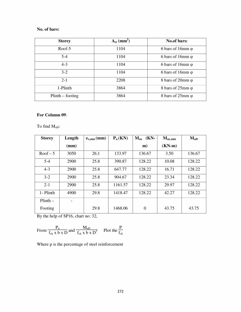
272
No. of bars:
Storey Ast (mm2) No.of bars:
Roof-5 1104 6 bars of 16mm φ
5-4 1104 6 bars of 16mm φ
4-3 1104 6 bars of 16mm φ
3-2 1104 6 bars of 16mm φ
2-1 2208 8 bars of 20mm φ
1-Plinth 3864 8 bars of 25mm φ
Plinth – footing 3864 8 bars of 25mm φ
For Column 09:
To find MuD:
Storey Length
(mm)
ex,min (mm) Pu (KN) Mux (KN-
m)
Mux,min
(KN-m)
MuD
Roof – 5 3050 26.1 133.97 136.67 3.50 136.67
5-4 2900 25.8 390.87 128.22 10.08 128.22
4-3 2900 25.8 647.77 128.22 16.71 128.22
3-2 2900 25.8 904.67 128.22 23.34 128.22
2-1 2900 25.8 1161.57 128.22 29.97 128.22
1- Plinth 4900 29.8 1418.47 128.22 42.27 128.22
Plinth –
Footing
-
29.8 1468.06 0 43.75 43.75
By the help of SP16, chart no: 32,
From Pu
fck x b x D and
MuD
fck x b x D2 Plot the
P
fck
Where p is the percentage of steel reinforcement

273
Storey Pu
fck x b x D
MuD
fck x b x D2
P
fck From chart
P (%)
Roof – 5 0.05 0.08 0.04 0.8
5-4 0.14 0.08 0.02 0.4
4-3 0.23 0.08 0.02 0.4
3-2 0.33 0.08 0.04 0.8
2-1 0.42 0.08 0.04 0.8
1- Plinth 0.51 0.08 0.06 1.2
Plinth – Footing 0.53 0.03 0.06 1.2
Provide min P = 0.8%
Ast = 0.8
100 x 230 x 600 = 1104 mm2
No. of bars of 16mmφ bars = 4 x 1104
π x (16)2 = 5.49 say 6 bars
For P=1.2%
Ast = 1.2
100 x 230 x 600 = 1656 mm
2
No. of bars of 20mmφ bars = 4 x 1656
π x (20)2 = 5.27 say 6 bars
Therefore provide 6 bars of 20mmφ bars.
Design of lateral ties:
1. Should not be less than 6mm
2. 1
4 x diameter of max main steel bar =
1
4 x 20 = 5mm
Maximum of two values =6mm.
But in the recent construction the usage of 6mm bars is outdated. Therefore consider
minimum 8mm dia bars.
Design of pitch:
1. Least lateral dimension = 230mm

274
2. 16 x diameter of main steel bar = 16 x 16 = 256
3. 300mm
Minimum of the above values is considered.
Therefore, provide 8mm φ bars @230mm c/c.
No. of bars:
Storey Ast (mm2) No.of bars:
Roof-5 1104 6 bars of 16mm φ
5-4 1104 6 bars of 16mm φ
4-3 1104 6 bars of 16mm φ
3-2 1104 6 bars of 16mm φ
2-1 1104 6 bars of 16mm φ
1-Plinth 1656 6 bars of 20mm φ
Plinth – footing 1656 6 bars of 20mm φ

275
6. DESIGN OF FOOTINGS
In the design of footing, the loads are known from the column analysis. The working load is
used for the footing design. Footing is a member through which the load of the superstructure
is transferred to the sub soil. Therefore the safe bearing capacity is the main factor in design
of footings. From the data provided by site engineer the Safe Bearing Capacity (SBC) of the
soil is 250 KN/m2. Therefore the footing is isolated rectangular sloped footing. The slope is
provided to decrease the amount of concrete in the construction which results into an
economic construction.
From the analysis of frames and columns, we considered 6 frames and each frame
consists of 3 footings so totally 18 footings are to be designed. But in this project we
designed the most critical 3 footings based on the load they carried are selected . the design
of remaining footings follow the same.
Footing F19:
Steel : Fe415
Concrete : M20
Column : 230mm x 600mm (bmm x Dmm)
Load from column (Pu) : 982.185 KN
Working load (P) : 982.185
1.5 = 654.79 KN
Self weight of footing : 10% of Pu
SBC of soil : 250 KN/m2
Area of footing (Af) : 1.1 x P
SBC of soil =
1.1 x 654.79
250 = 2.88 m
2
Consider, D-b
2 =
600 - 230
2 = 185 mm
Length of footing (Lf) = 185mm + (√(185)2 + 2.88 x 10
6 ) = 1892.11
say 1900mm
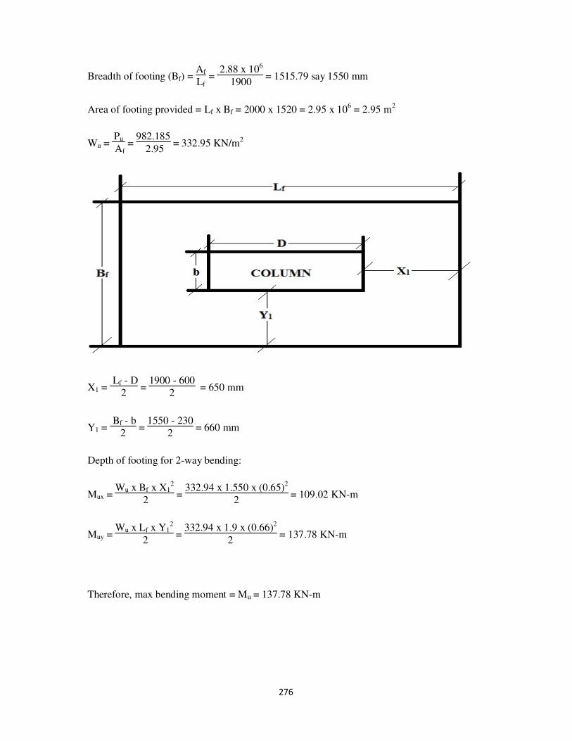
276
Breadth of footing (Bf) = Af
Lf =
2.88 x 10⁶
1900 = 1515.79 say 1550 mm
Area of footing provided = Lf x Bf = 2000 x 1520 = 2.95 x 106 = 2.95 m
2
Wu = Pu
Af =
982.185
2.95 = 332.95 KN/m2
X1 = Lf - D
2 =
1900 - 600
2 = 650 mm
Y1 = Bf - b
2 =
1550 - 230
2 = 660 mm
Depth of footing for 2-way bending:
Mux = Wu x Bf x X1
2
2 =
332.94 x 1.550 x (0.65)2
2 = 109.02 KN-m
Muy = Wu x Lf x Y1
2
2 =
332.94 x 1.9 x (0.66)2
2 = 137.78 KN-m
Therefore, max bending moment = Mu = 137.78 KN-m

277
b' = b + 2 x e = 230 + 2 x 50 = 330 mm
D' = D + 2 x e = 600 + 2 x 50 = 700 mm
Clear cover = 50mm
Assume 10mm bars
d'x = 50 + 10
2 = 55mm
d'y = 50 + (3 x 10
2 )= 65mm

278
Depth of foundation:
(Df)x = + d'x = √109.02 x 10
6
0.138 x 20 x 330 + 55 = 400.97 mm
(Df)y = + d'y = √137.78 x 10
6
0.138 x 20 x 700 + 65 = 332.05 mm
Therefore, maximum (Df) = 400.97 mm say 450mm
Therefore dx = 450 – 55 = 395mm
dy = 450 – 65 = 385mm
Provide Df,min = 150mm
df,min ( x-direction) = 150 - 55 = 95mm
df,min ( y-direction) = 150 - 65 = 85mm

279

280
Check for two way shear:
Consider a section ‘ dy
2 ’ from the face of the column.
L2 = D + dy
2 +
dy
2 = 600 + 385 = 985 mm
B2 = b + dy
2 +
dy
2 = 230 + 385 = 615 mm
d2 = Df – (Df – Df,min) x
(dy
2 - 50)
(X1 - 50) – d'y
= 450 – (450 – 150) x
(385
2 - 50)
(650 - 50) – 65 = 313.75 mm
Area of resisting shear (A2) = 2 x(L2 + B2) x d2
= 2 x (985 + 615) x 313.75
= 1004000 mm2
Shear strength of concrete for two way:
τuc2 = ks x τuc
where, τuc = 0.25 x √fck = 0.25 x √20 = 1.12 N/mm2
ks = (0.5 + βc) < 1 else =1
βc = b
D =
230
600 = 0.385
therefore, ks = (0.5 + βc) = 0.5 + 0.385 = 0.885 <1
ks = 0.885
τuc2 = ks x τuc = 0.885 x 1.12 = 0.99 N/mm2
Internal load carrying capacity (Vuc2) = 1004000 x 0.99 = 993960 N
= 993.96 KN
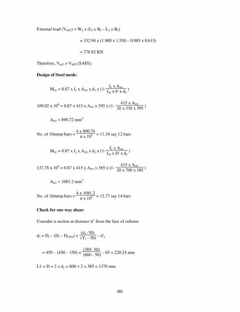
281
External load (VuD2) = Wu x (Lf x Bf – L2 x B2)
= 332.94 x (1.900 x 1.550 – 0.985 x 0.615)
= 778.82 KN
Therefore, Vuc2 > VuD2 (SAFE)
Design of Steel mesh:
Mux = 0.87 x fy x Astx x dx x (1-fy x Astx
fck x b' x dx )
109.02 x 106 = 0.87 x 415 x Astx x 395 x (1-
415 x Astx
20 x 330 x 395 )
Astx = 890.72 mm2
No. of 10mmφ bars = 4 x 890.74
π x 102 = 11.34 say 12 bars
Muy = 0.87 x fy x Asty x dy x (1-fy x Astx
fck x D' x dy )
137.78 x 106 = 0.87 x 415 x Astx x 385 x (1-
415 x Astx
20 x 700 x 385 )
Asty = 1081.2 mm2
No. of 10mmφ bars = 4 x 1081.2
π x 102 = 13.77 say 14 bars
Check for one way shear:
Consider a section at distance‘d’ from the face of column
d1 = Df – (Df – Df,min) x (dy- 50)
(Y1 - 50) – d'y
= 450 – (450 – 150) x (385- 50)
(660 - 50) – 65 = 220.24 mm
L1 = D + 2 x dy = 600 + 2 x 385 = 1370 mm

282
Area resisting shear (A1) = (Lf x Dy,min) + (d1 – Dy,min) x ( Lf + L1
2 )
= (1900 x 150) + (220.24 – 150) x ( 1900 + 1370
2 )
= 399842.4 mm2
Asty = 14 bars of 10mm dia = 1099.56 mm2
Pt = 100 x Asty
A1 =
100 x 1099.56
399842.4 = 0.28
From IS456-2000, P73, Table 19
P τc (N/mm2)
0.25 0.36
0.28 ?
0.50 0.48
τc = 0.36 + (0.48 - 0.36)
(0.5 - 0.25) x (0.28 – 0.25) = 0.38 N/mm
2
Internal shear resisting capacity = 0.38 x 399842.4
1000 = 151.94 KN
External shear = Wu x Lf x (Y1 – dy)
= 332.94 x 1.900 x (0.660 – 385)
= 173.96 KN
Internal shear resisting capacity < External Shear (NOT SAFE)
Increase the depth.
Shear = load
area
0.38 = 173.96 x 10
3
A1

283
A1 =457789.47 mm2
To calculate d1:
A1 = (Lf x Dy,min) + (d1 – Dy,min) x ( Lf + L1
2 )
457789.47 = (1900 x 150) + (d1 – 150) x ( 1900 + 1370
2 )
d1 = 255.68 mm
Footing F11:
Load from column (Pu) : 2861.68 KN
Working load (P) : 2861.68
1.5 = 1907.79 KN
Self weight of footing : 10% of Pu
SBC of soil : 250 KN/m2
Area of footing (Af) : 1.1 x P
SBC of soil =
1.1 x 1907.79
250 = 8.4 m
2
Consider, D-b
2 =
600 - 230
2 = 185 mm
Length of footing (Lf) = 185mm + (√(185)2 + 8.4 x 10
6 ) = 3089.17
say 3100mm
Breadth of footing (Bf) = Af
Lf =
8.4 x 10⁶
3100 = 2709.67 say 2725 mm
Area of footing provided = Lf x Bf = 3100 x 2725 = 8.45 x 106 = 8.45 m
2
Wu = Pu
Af =
2861.68
8.45 = 338.66 KN/m
2
X1 = Lf - D
2 =
3100 - 600
2 = 1250 mm
Y1 = Bf - b
2 =
2725 - 230
2 = 1247.5 mm

284
Depth of footing for 2-way bending:
Mux = Wu x Bf x X1
2
2 =
338.66 x 2.725 x (1.25)2
2 = 720.98 KN-m
Muy = Wu x Lf x Y1
2
2 =
338.66 x 3.1 x (1.2475)2
2 = 816.92 KN-m
Therefore, max bending moment = Mu = 816.92 KN-m
b' = b + 2 x e = 230 + 2 x 50 = 330 mm
D' = D + 2 x e = 600 + 2 x 50 = 700 mm
Clear cover = 50mm
Assume 16mm bars
d'x = 50 + 16
2 = 58 mm
d'y = 50 + (3 x16
2 ) = 74 mm
Depth of foundation:
(Df)x = + d'x = √720.98 x 10
6
0.138 x 20 x 330 + 58 = 947.71 mm
(Df)y = + d'y = √816.92 x 10
6
0.138 x 20 x 700 + 74 = 724.26 mm
Therefore, maximum (Df) = 947.71 mm say 1000mm
Therefore dx = 1000 – 58 = 942 mm
dy = 1000 – 74 = 926 mm
Provide Df,min = 150mm
df,min ( x-direction) = 150 - 58 = 92 mm
df,min ( y-direction) = 150 - 74 = 76 mm

285
Check for two way shear:
Consider a section ‘ dy
2 ’ from the face of the column.
L2 = D + dy
2 +
dy
2 = 600 + 926 = 1526 mm
B2 = b + dy
2 +
dy
2 = 230 + 926 = 1156 mm
d2 = Df – (Df – Df,min) x
(dy
2 - 50)
(X1 - 50) – d'y
= 1000 – (1000 – 150) x
(926
2 - 50)
(1250 - 50) – 74 = 633.45 mm
Area of resisting shear (A2) = 2 x(L2 + B2) x d2
= 2 x (1526 + 1156) x 633.45
= 3.4 x 106 mm2
Shear strength of concrete for two way:
τuc2 = ks x τuc
where, τuc = 0.25 x √fck = 0.25 x √20 = 1.12 N/mm2
ks = (0.5 + βc) < 1 else =1
βc = b
D =
230
600 = 0.385
Therefore, ks = (0.5 + βc) = 0.5 + 0.385 = 0.885 <1
ks = 0.885
τuc2 = ks x τuc = 0.885 x 1.12 = 0.99 N/mm2

286
Internal load carrying capacity (Vuc2) = 3.4 x 106 x 0.99 = 3.37 x 10⁶ N
= 3370 KN
External load (VuD2) = Wu x (Lf x Bf – L2 x B2)
= 338.66 x (3.1 x 2.725 – 1.526 x 1.156)
= 2263.41 KN
Therefore, Vuc2 > VuD2 (SAFE)
Design of Steel mesh:
Mux = 0.87 x fy x Astx x dx x (1-fy x Astx
fck x b' x dx )
720.98 x 106 = 0.87 x 415 x Astx x 942 x (1-
415 x Astx
20 x 330 x 942 )
Astx = 2555.91 mm2
No. of 16mmφ bars = 4 x 2555.91
π x 162 = 12.71 say 13 bars
Muy = 0.87 x fy x Asty x dy x (1-fy x Astx
fck x D' x dy )
816.92 x 106 = 0.87 x 415 x Astx x 926 x (1-
415 x Astx
20 x 700 x 926 )
Asty = 2671.98 mm2
No. of 16mmφ bars = 4 x 2671.98
π x 162 = 13.29 say 14 bars
Check for one way shear:
Consider a section at distance‘d’ from the face of column
d1 = Df – (Df – Df,min) x (dy- 50)
(Y1 - 50) – d'y
= 1000 – (1000 – 150) x (926- 50)
(1247.5 - 50) – 74 = 304.21 mm

287
L1 = D + 2 x dy = 600 + 2 x 926 = 2452 mm
Area resisting shear (A1) = (Lf x Dy,min) + (d1 – Dy,min) x ( Lf + L1
2 )
= (3100 x 150) + (304.21 – 150) x ( 3100 + 2452
2 )
= 893086 mm2
Asty = 14 bars of 10mm dia = 2814.87 mm2
Pt = 100 x Asty
A1 =
100 x 2814.87
893086 = 0.32
From IS456-2000, P73, Table 19
P τc (N/mm2)
0.25 0.36
0.32 ?
0.5 0.48
τc = 0.36 + (0.48 - 0.36)
(0.5 - 0.25) x (0.32 – 0.25) = 0.4 N/mm
2
Internal shear resisting capacity = 0.4 x 893086
1000 = 357.23 KN
External shear = Wu x Lf x (Y1 – dy)
= 338.66 x 3.1 x (1.2475 – 0.926)
= 337.53 KN
Internal shear resisting capacity > External Shear (SAFE)
Footing F07:
Load from column (Pu) : 1922.71 KN
Working load (P) : 1922.71
1.5 = 1281.81 KN

288
Self weight of footing : 10% of Pu
SBC of soil : 250 KN/m2
Area of footing (Af) : 1.1 x P
SBC of soil =
1.1 x 1281.81
250 = 5.64 m
2
Consider, D-b
2 =
600 - 230
2 = 185 mm
Length of footing (Lf) = 185mm + (√(185)2 + 5.64 x 10⁶ ) = 2567.06
say 2575mm
Breadth of footing (Bf) = Af
Lf =
5.64 x 10⁶
2575 = 2190.29 say 2200 mm
Area of footing provided = Lf x Bf = 2575 x 2200 = 5.665 x 106 = 5.665 m
2
Wu = Pu
Af =
1922.71
5.665 = 339.4 KN/m2
X1 = Lf - D
2 =
2575 - 600
2 = 987.5 mm
Y1 = Bf - b
2 =
2200 - 230
2 = 985 mm
Depth of footing for 2-way bending:
Mux = Wu x Bf x X1
2
2 =
339.4 x 2.2 x (0.9875)2
2 = 364.06 KN-m
Muy = Wu x Lf x Y1
2
2 =
339.4 x 2.575 x (0.985)2
2 = 423.97 KN-m
Therefore, max bending moment = Mu = 423.97 KN-m
b' = b + 2 x e = 230 + 2 x 50 = 330 mm
D' = D + 2 x e = 600 + 2 x 50 = 700 mm
Clear cover = 50mm
Assume 12mm bars

289
d'x = 50 + 12
2 = 56 mm
d'y = 50 + (3 x12
2 ) = 68 mm
Depth of foundation:
(Df)x = + d'x = √364.06 x 10⁶
0.138 x 20 x 330 + 56 = 688.23 mm
(Df)y = + d'y = √423.97 x 10
6
0.138 x 20 x 700 + 68 = 536.45 mm
Therefore, maximum (Df) = 688.23 mm say 700mm
Therefore dx = 700 – 56 = 644 mm
dy = 700 – 68 = 632 mm
Provide Df,min = 150mm
df,min ( x-direction) = 150 - 56 = 94 mm
df,min ( y-direction) = 150 - 68 = 82 mm
Check for two way shear:
Consider a section ‘ dy
2 ’ from the face of the column.
L2 = D + dy
2 +
dy
2 = 600 + 632 = 1232 mm
B2 = b + dy
2 +
dy
2 = 230 + 632 = 862 mm
d2 = Df – (Df – Df,min) x
(dy
2 - 50)
(X1 - 50) – d'y
= 700 – (700 – 150) x
(632
2 - 50)
(987.5 - 50) – 68 = 475.95 mm

290
Area of resisting shear (A2) = 2 x(L2 + B2) x d2
= 2 x (1232 + 862) x 475.95
= 1993278.6 mm2
Shear strength of concrete for two way:
τuc2 = ks x τuc
where, τuc = 0.25 x √fck = 0.25 x √20 = 1.12 N/mm2
ks = (0.5 + βc) < 1 else =1
βc = b
D =
230
600 = 0.385
therefore, ks = (0.5 + βc) = 0.5 + 0.385 = 0.885 <1
ks = 0.885
τuc2 = ks x τuc = 0.885 x 1.12 = 0.99 N/mm2
Internal load carrying capacity (Vuc2) = 1993278.6x 0.99 = 1973345.814N
= 1973.35 KN
External load (VuD2) = Wu x (Lf x Bf – L2 x B2)
= 339.4 x (2.575 x 2.2 – 1.232 x 0.862)
= 1562.27 KN
Therefore, Vuc2 > VuD2 (SAFE)
Design of Steel mesh:
Mux = 0.87 x fy x Astx x dx x (1-fy x Astx
fck x b' x dx )
364.06 x 106 = 0.87 x 415 x Astx x 644 x (1- 415 x Astx
20 x 330 x 644 )

291
Astx = 1929.08 mm2
No. of 12mmφ bars = 4 x 1929.08
π x 122 = 17.1 say 18 bars
Muy = 0.87 x fy x Asty x dy x (1-fy x Astx
fck x D' x dy )
423.06 x 106 = 0.87 x 415 x Astx x 632 x (1-
415 x Astx
20 x 700 x 632 )
Asty = 2051.42 mm2
No. of 12mmφ bars = 4 x 2051.42
π x 122 = 18.13 say 19 bars
Check for one way shear:
Consider a section at distance‘d’ from the face of column
d1 = Df – (Df – Df,min) x (dy- 50)
(Y1 - 50) – d'y
= 700 – (700 – 150) x (632- 50)
(985 - 50) – 68 = 289.65 mm
L1 = D + 2 x dy = 600 + 2 x 632 = 1864 mm
Area resisting shear (A1) = (Lf x Dy,min) + (d1 – Dy,min) x ( Lf + L1
2 )
= (2575 x 150) + (289.65 – 150) x ( 2575 + 1864
2 )
= 696203.175 mm2
Asty = 19 bars of 12mm dia = 2148.84 mm2
Pt = 100 x Asty
A1 =
100 x 2148.84
696203.175 = 0.31
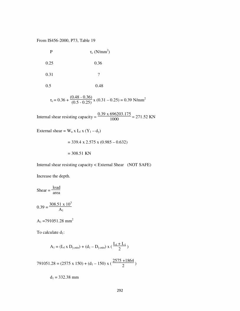
292
From IS456-2000, P73, Table 19
P τc (N/mm2)
0.25 0.36
0.31 ?
0.5 0.48
τc = 0.36 + (0.48 - 0.36)
(0.5 - 0.25) x (0.31 – 0.25) = 0.39 N/mm2
Internal shear resisting capacity = 0.39 x 696203.175
1000 = 271.52 KN
External shear = Wu x Lf x (Y1 – dy)
= 339.4 x 2.575 x (0.985 – 0.632)
= 308.51 KN
Internal shear resisting capacity < External Shear (NOT SAFE)
Increase the depth.
Shear = load
area
0.39 = 308.51 x 10
3
A1
A1 =791051.28 mm2
To calculate d1:
A1 = (Lf x Dy,min) + (d1 – Dy,min) x ( Lf + L1
2 )
791051.28 = (2575 x 150) + (d1 – 150) x ( 2575 +1864
2 )
d1 = 332.38 mm

293
7. DESIGN OF STAIR CASE
Stairs consist of steps arranged in a series for purpose of giving access to different floors of a
building. Since a stair is often the only means of communication between the various floors
of a building, the location of the stair requires good and careful consideration. In a residential
house, the staircase may be provided near the main entrance. In a public building, the stairs
must be from the main entrance itself and located centrally, to provide quick accessibility to
the principal apartments. All staircases should be adequately lighted and properly ventilated.
Various types of Staircases
Straight stairs
Dog-legged stairs
Open newel stair
Geometrical stair
RCC design of a Dog-legged staircase
In this type of staircase, the succeeding flights rise in opposite directions. The two
flights in plan are not separated by a well. A landing is provided corresponding to the level at
which the direction of the flight changes.
Dimensions:
B x L x H = 2820mm x 6000mm x 3350mm
Assume, Rise = 150mm
Tread = 300mm
sec θ = √(150)2+(300)2
300 = 1.12
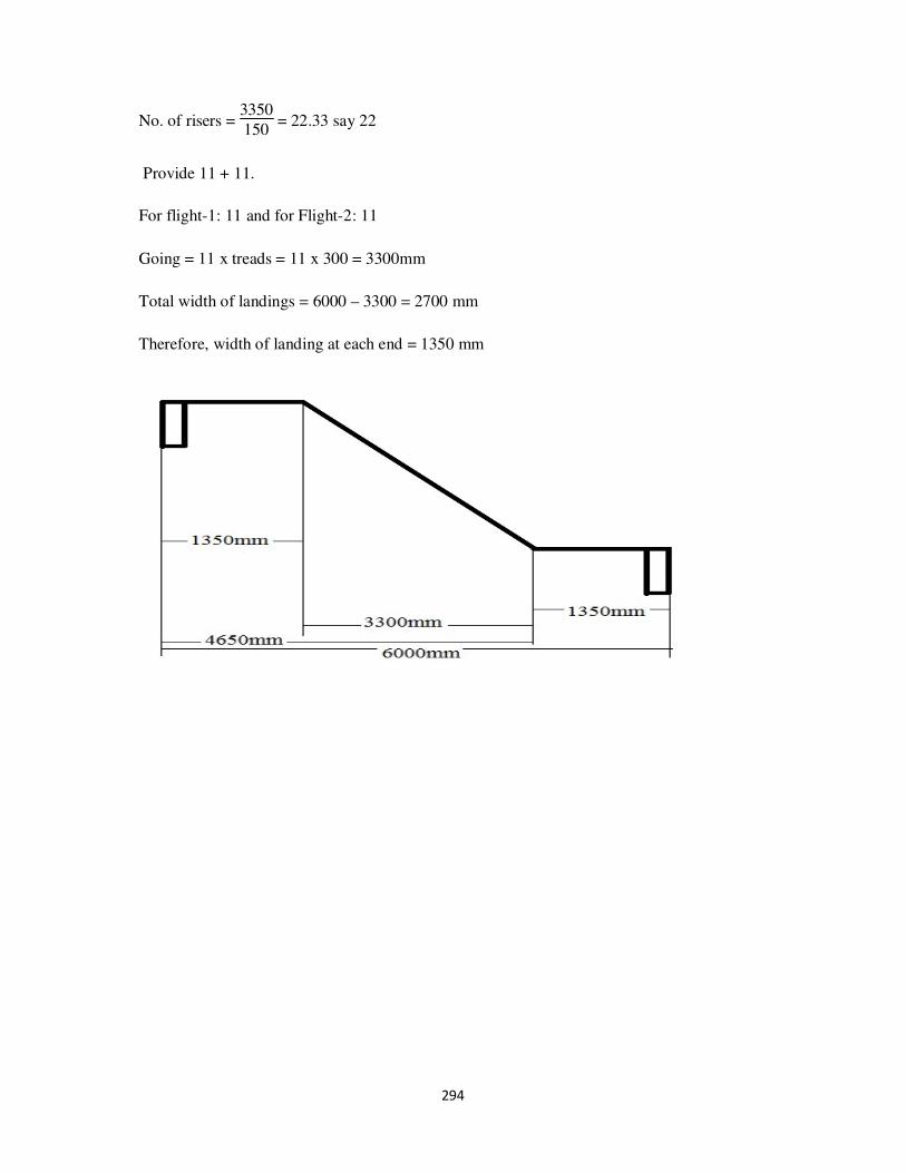
294
No. of risers = 3350
150 = 22.33 say 22
Provide 11 + 11.
For flight-1: 11 and for Flight-2: 11
Going = 11 x treads = 11 x 300 = 3300mm
Total width of landings = 6000 – 3300 = 2700 mm
Therefore, width of landing at each end = 1350 mm

295
Design of Flight -1:
Type: One way single span simply supported inclined slab
Span (L): 3300 + 1350 = 4650mm
Trail Depth:
From IS456-2000, P39, Clause 24 & Clause 23.2 for Simply supported span we have
Span
Effective depth =
L
d = 20
ra = 20 x 1.4 = 28
Therefore, D = 4750
28 + 20 = 189.65mm say 200 mm
Effective depth (d) = D – d1 = 200 – 20 = 180mm

296
Loads:
Self weight of slab (inclined) = 25 x D x secθ
= 25 x 0.2 x 1.12
= 5.6 KN/m2
Weight of steps = 25 x rise x secθ
2 =
25 x 0.15 x 1.1
2
= 2.09 KN/m2
Live load = 5 KN/m2
Floor Finish = 1 KN/m2
Total Load (W) = 13.69 KN/m2
Ultimate load (Wu) = 1.5 x 13.69 = 20.54 KN/m2
Design moment (Mu) = Wu x L
2
10 =
20.54 x (4.65)2
10 = 44.41 KN-m
Mu,limit = 0.138 x fck x b x d2 = 0.138 x 20 x 1000 x (180)
2
= 89.42 x 10⁶ N-mm = 89.42 KN-m
Mu < Mu,limit
Main steel:
From IS456-2000, P96, Clause G-1.1 (b) we have
Mu = 0.87 x fy x Ast x d x (1 - fy x Ast
fck x b x d )
44.7 x 106 = 0.87 x 415 x Ast x 180 x (1 -
415 x Ast
20 x 1000 x 180 )
Ast = 753.21 mm2
Spacing of 12mm φ bars = ast x 1000
Ast = π4 x 12
2 x
1000
753.21 = 150.15mm

297
Therefore, Provide 12mm φ @ 150mm c/c.
Distribution steel:
Ast = 0.12% of Ag
= 0.12
1000 x 200 x 1000 = 240 mm2.
Spacing of 8mm φ bars = π4 x 8
2 x
1000
240 = 209.44mm
Therefore, Provide 8mm φ @ 200mm c/c.
Design of flight-2:
Same as design of flight-1.

298
8. CONCLUSION
The complete details and the necessity of the Multi-Storeyed building have been
explained in the introduction part. Live loads and dead loads are taken into consideration and
analysis is done manually. Manual analysis comprises of load distribution of slabs on to
beams and calculation of bending moment and shear force by any approximate method.
Analysis of frames is done by the substitute frame method and is furnished in the
introduction part. With the help of moment distribution method the moments carried at each
joints are known.
The design method adopted is limit state method. The bending moments obtained from
chapter 4 are used in calculating the area of steel in each frame section. The percentage of
steel obtained by limit state method is minimum as mentioned in limit state method of IS
456-2000.
Design of columns and footings are done depending on the load acting on them.
This project explains the basic concept behind the software. With the help of any software
we can do this analysis within no time but the basic thing is to know the concept behind it.
The same result can be achieved using the software like “Staad-Pro”. The wind load and
seismic analysis can be included for the future extension of the project.

299
9. REFERENCE
I. Design of Reinforced Concrete Structures by A. K. Jain
II. Illustrated design of reinforced concrete buildings by Dr.V.L. Shah & Dr.S.R.Karve
III. Basic Principles of Analysis and Design of an RCC Framed Structures by Prof. H. R.
Surya Prakash S. Krishna Murthy
IV. Design of R.C.C structural elements by S.S. Bhavikatti
V. Design of R.C.C slabs by K.C.Jain
VI. R.C.C Design and Drawing by Neelam Sharma
VII. Treasure of R.C.C Designs by Sushil kumar
VIII. Design of R.C.C structures by prof.N.Krishna Raju
IX. Design of R.C.C structures by prof.S.Ramamrutham X. R.C.C design by S.Unnikrishina pillai & Devdas Menon
XI. The code books referred for this project are:
● IS 456:2000 (reinforced concrete for general building construction)
● IS 875, part 1, 1987(dead loads for building and structures)
● IS 875, part 2, 1987(imposed loads for buildings and structures)
● SP 16 (design aids for IS 456)