Embed Size (px)
Citation preview

CD80 Digital Pack
Instruction Sheet Part #: 2-450161-010Revision Level: 4.2 Written By: Don LammersRevised By: Charles ColeyRevision Date: 10/30/08
The material in this manual is for information purposes only and is subject to change without notice. Strand Lighting assumes no responsibility for any errors or omissions which may appear in this manual. For comments and suggestions regarding corrections and/or updates to this manual, please contact your nearest Strand Lighting office.
El contenido de este manual es solamente para información y está sujeto a cambios sin previo aviso. Strand Lighting no asume responsabilidad por errores o omisiones que puedan aparecer. Cualquier comentario, sugerencia o corrección con respecto a este manual, favor de dirijirlo a la oficina de Strand Lighting más cercana.
Der Inhalt dieses Handbuches ist nur für Informationszwecke gedacht, Aenderungen sind vorbehalten. Strand Lighting uebernimmt keine Verantwortung für Fehler oder Irrtuemer, die in diesem Handbuch auftreten. Für Bemerkungen und Verbesserungsvorschlaege oder Vorschlaege in Bezug auf Korrekturen und/oder Aktualisierungen in diesem Handbuch, moechten wir Sie bitten, Kontakt mit der naechsten Strand Lighting-Niederlassung aufzunehmen.
Le matériel décrit dans ce manuel est pour information seulement et est sujet à changements sans préavis. La compagnie Strand Lighting n'assume aucune responsibilité sur toute erreur ou ommission inscrite dans ce manuel. Pour tous commentaires ou suggestions concernant des corrections et/ou les mises à jour de ce manuel, veuillez s'll vous plait contacter le bureau de Strand Lighting le plus proche.
6603 Darin Way, Cypress, CA 90630 Tel: 1-714-230-8200 Fax: 1-714-899-004215
Copyright 1992, 2007, Strand Lighting, Inc. All rights reserved.
Information contained in this document may not be duplicated in full or in part by any person without prior written approval of Strand Lighting. Its sole purpose is to provide the user with detailed operational information for the equipment supplied. The use of this document for all other purposes is specifically prohibited.
Strand Lighing North America Office:
Table of Contents i
Table of Contents
Introduction and Assistance ............................................... 1 Manual Organization ......................................................................... 1 Definitions ......................................................................................... 2 Conventions ....................................................................................... 3 Technical Assistance ......................................................................... 3
Problems ....................................................................................... 3 Technical Questions ..................................................................... 3 Parts Purchases ............................................................................. 3 Comments and Suggestions .......................................................... 3 Addresses ..................................................................................... 3
Operational Features ........................................................... 5 Protocol.............................................................................................. 5 Configuration ..................................................................................... 5 Dimming Characteristics ................................................................... 5
Regulation .................................................................................... 5 Output ........................................................................................... 5 Efficiency ..................................................................................... 6
Protection ........................................................................................... 6 Dimmer Level Retention ................................................................... 6 Servicing ............................................................................................ 6
Hardware Description .......................................................... 7 Chassis ............................................................................................... 8 Digital Controller ............................................................................... 9
Control Module Front Panel ......................................................... 9 Controller Electronics................................................................. 10
Power Control and Cooling Assemblies .......................................... 10 Dimmer Types ................................................................................. 10 Input Power Connectors .................................................................. 10
Installation .......................................................................... 11 Preparation ....................................................................................... 11
Environmental Considerations ................................................... 11 Power Requirements ................................................................... 11 Plan Pack Positioning ................................................................. 11 Plan Wiring Layout .................................................................... 12
Installation ....................................................................................... 14 Install Pack ................................................................................. 14 Set Correct Phasing .................................................................... 14 Connect Power ........................................................................... 15 Connect Load Wires ................................................................... 15 Connect Control Wires ............................................................... 15
Table of Contents ii
Processor Setup ................................................................. 17 Processor Setup ............................................................................... 17
Main Menu ................................................................................. 17 Set Level ..................................................................................... 18 DMX512 Address ...................................................................... 19 Dimming Curve .......................................................................... 20 Set Minimum Level .................................................................... 21 Set Maximum Level ................................................................... 22 Setup ........................................................................................... 22 Response Time ........................................................................... 24 DMX Port ................................................................................... 25 DMX Fail ................................................................................... 25 Version Number ......................................................................... 26 Set Factory Default ..................................................................... 27
Combining Pack Types .................................................................... 27 Dimmer Number Offset ................................................................... 27
Using DMX512 Dimmer Control ............................................... 28 Fault Protection ............................................................................... 29 Hot Pocket ....................................................................................... 29 Local Dimmer Control ..................................................................... 29
Dimmer Panic ............................................................................. 29 ON/NORMAL Push-buttons ..................................................... 30
Retrofitting an Analog Pack ............................................................ 30
Basic Trouble-shooting ..................................................... 31 Component Removal ....................................................................... 31
Controller Replacement .............................................................. 31 SSR Replacement ....................................................................... 32 Problems Affecting the Entire Pack ........................................... 33 Problems Confined to a Single Phase ......................................... 34 Individual Dimmer Problems ..................................................... 35
Periodic Maintenance......................................................... 37
Table of Contents iii
Table of Figures Figure 1. CD80 Digital Pack........................................................................ 7 Figure 2. CD80 Digital Pack Controller ...................................................... 9 Figure 3. CD80 Pack Wall Mounting ........................................................ 12 Figure 4. DMX512 Dimmer Control Extension Cable .............................. 15 Figure 5. Menu - Main Menu .................................................................... 17 Figure 6. Menu – Set Level ....................................................................... 18 Figure 7. Menu – DMX512 Address ......................................................... 19 Figure 8. Menu – Dimming Curve ............................................................. 20 Figure 9. Menu – Set Minimum Level ...................................................... 21 Figure 10. Menu – Set Maximum Level .................................................... 22 Figure 11. Menu – Setup ........................................................................... 23 Figure 12. Menu – Response Time ............................................................ 24 Figure 13. Menu – Response Time ............................................................ 25 Figure 14. Menu – DMX Fail .................................................................... 26 Figure 15. Menu – Set Factory Default ..................................................... 27 Figure 16. Connect Packs for DMX512 .................................................... 28 Figure 17. Digital Dimmer Controller Removal ........................................ 31 Figure 18. 2.4Kw Digital Pack Parts ......................................................... 38 Figure 19. 6Kw Digital Pack Parts ............................................................ 39 Figure 20. 12Kw Digital Pack Parts .......................................................... 40
Table of Tables Table 1. DMX512 Control Inputs .............................................................. 15

Table of Contents iv
Introduction and Assistance 1
Chapter Introduction and Assistance
This manual provides information on the operating procedures for the CD80 Digital Dimmer Pack.
This manual contains the chapters shown below, plus an Index.
Introduction and Assistance (chapter 1) - tells you about the organization of this manual, plus definitions and conventions used. Also tells you how to get technical help if necessary
Operational Features (chapter 2) - gives an overview of the operational features of CD80 Digital Packs.
Hardware Description (chapter 3) - gives an overview of the hardware and how it works together.
Installation (chapter 4) - tells you about the installation requirements for CD80 Digital Packs and peripherals. This chapter shows pinouts for externally accessible connectors, cable types and lengths, and (where applicable) setup information.
Basic Trouble-shooting (chapter 5) - tells you how to begin trouble-shooting if you have problems with a pack. Since actual internal repair of the pack electronics is beyond the scope of this manual, this chapter shows only the basic steps you can take without having to replace individual circuit parts, and before you call for help from Strand Lighting.
Periodic Maintenance (chapter 6) - lists the steps which should be taken to keep your Digital Packs running at their best.
1
Manual Organization
Introduction and Assistance
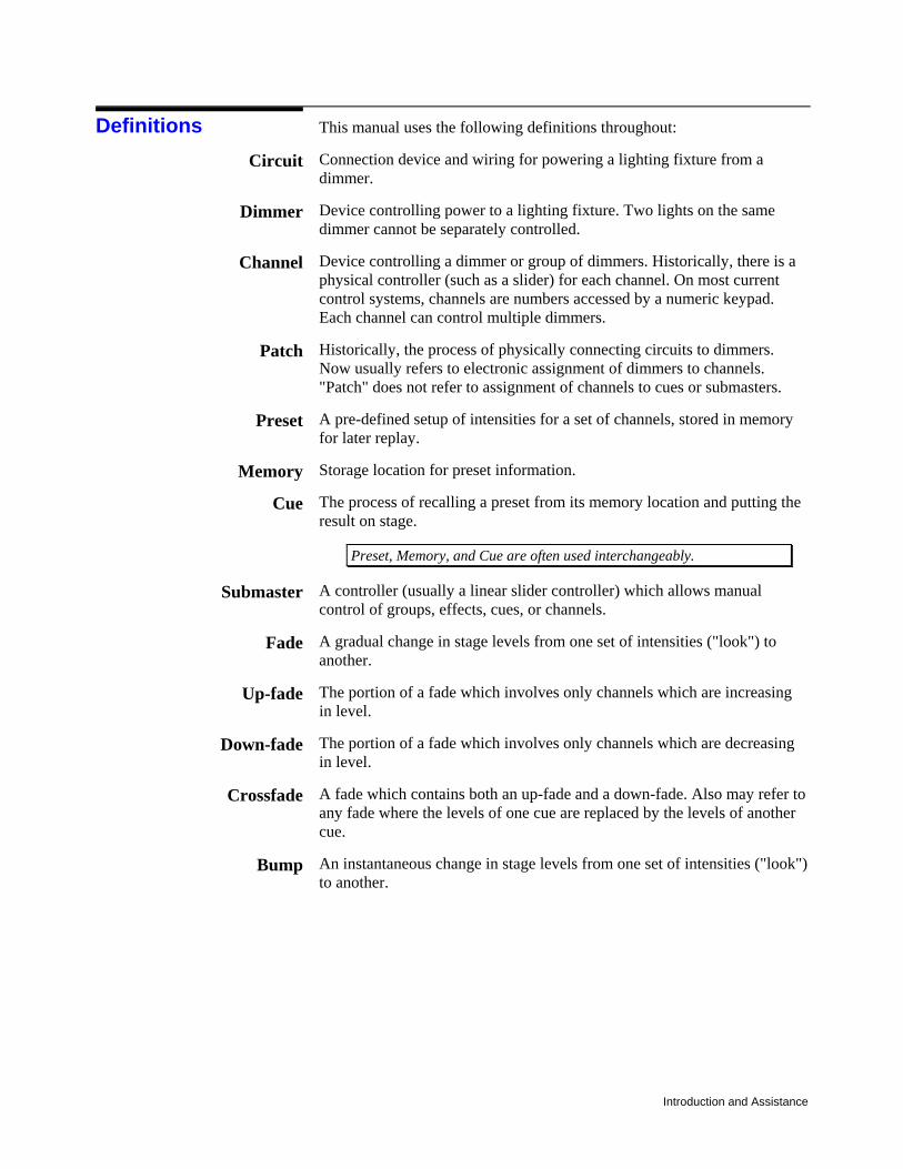
This manual uses the following definitions throughout:
Connection device and wiring for powering a lighting fixture from a dimmer.
Device controlling power to a lighting fixture. Two lights on the same dimmer cannot be separately controlled.
Device controlling a dimmer or group of dimmers. Historically, there is a physical controller (such as a slider) for each channel. On most current control systems, channels are numbers accessed by a numeric keypad. Each channel can control multiple dimmers.
Historically, the process of physically connecting circuits to dimmers. Now usually refers to electronic assignment of dimmers to channels. "Patch" does not refer to assignment of channels to cues or submasters.
A pre-defined setup of intensities for a set of channels, stored in memory for later replay.
Storage location for preset information.
The process of recalling a preset from its memory location and putting the result on stage.
Preset, Memory, and Cue are often used interchangeably.
A controller (usually a linear slider controller) which allows manual control of groups, effects, cues, or channels.
A gradual change in stage levels from one set of intensities ("look") to another.
The portion of a fade which involves only channels which are increasing in level.
The portion of a fade which involves only channels which are decreasing in level.
A fade which contains both an up-fade and a down-fade. Also may refer to any fade where the levels of one cue are replaced by the levels of another cue.
An instantaneous change in stage levels from one set of intensities ("look") to another.
Definitions Circuit
Dimmer
Channel
Patch
Preset
Memory
Cue
Submaster
Fade
Up-fade
Down-fade
Crossfade
Bump
Introduction and Assistance 3
The following conventions are used in this manual:
(all capital text) shows to the status of a function or switch, as in "Turn the switch ON."
(text with first letter capitalized) shows the name of a function or mode of operation, as in Live mode, Group function, or Preview display.
CD80 Digital Dimmer Packs require a minimum of maintenance and servicing.
If equipment fails to operate properly upon installation, or under normal load and temperature conditions, and basic trouble-shooting procedures are not effective, please contact Strand Lighting Field Service or an Authorized Service Center serving your area. Strand Lighting will issue a Return Goods Authorization before the return of any defective materials. This allows tracking of returned equipment, and speeds its return to you.
For technical questions regarding setup, operation, or maintenance of this equipment, please contact the Strand Lighting Field Service or an Authorized Service Center serving your area.
For purchase of spare parts or documentation, please contact Strand Lighting Customer Service or an Authorized Service Center serving your area.
For comments regarding equipment functions and/or possible improvements, or for comments on this manual, please call or write to the Customer Service Manager at the Strand Lighting office serving your area.
Contact information for all the Strand Lighting offices are shown on the reverse side of the manual title sheet and on our web-site: www.strandlighting.com or call 1 (800) 4-STRAND (1-800-478-7263).
Contact information for all local Authorized Service Centers are located on our web-site: www.strandlighting.com
Conventions ON
Live
Technical Assistance
Problems
Technical Questions
Parts Purchases
Comments andSuggestions
Addresses

Introduction and Assistance
Operational Features 5
Chapter Operational Features
This chapter presents the basic operational features of the CD80 Digital Pack.
The CD80 Digital Pack Controller will accept DMX512 digital dimmer protocol.
One CD80 Digital Pack contains twenty-four 2.4Kw dimmers, twelve 2.4Kw dimmers, or six 6Kw or 12Kw dimmers.
The controller can be set to start "reading" dimmer levels at any dimmer number required (1-512 for DMX512 signals). This provides maximum flexibility in using CD80 Digital Dimmer Packs with multiple consoles and/or other types of packs or dimmers.
The 12 channel controller can be set to read 12 consecutive control signals and control either 12 or 6 consecutive dimmers, or to read every other signal of 12 to control 6 consecutive dimmers. The second option is used for systems where the 6Kw/12Kw assignments will be handled by the console patch.
120VAC dimmer module, with circuitry in the Digital Controller module, regulates output voltage with changes in the AC line from 108 to 130 volts RMS.
Dimmers will maintain output RMS voltage within ±2% with changes in load from 10 watts to full rated load at any point on the dimming curve (30 watts to full rated load for 12Kw Packs).
Output RMS voltage versus setting follows a modified square law dimming curve.
Output waveform is a variable conduction angle 120VAC sine wave. Output waveform risetime is greater than 500 microseconds. Output response time (from control signal change) is less than 0.1 seconds.
2
Protocol
Configuration
Dimming Characteristics
Regulation
Output
Operational Features
Output connections can be Grounded Twist Lock, Pin Plug, U-Ground (2.4Kw Packs only).
The power efficiency of the dimmer is a minimum of 95% at full load.
Front panel overtemperature indication. The OverTemp thermostat will turn OFF all dimmers in the pack when the temperature on the pack heat sink is 0greater than 85°C.
Solid State Relay Peak Surge Rating: • 2.4Kw Pack - 600 Amps. • 6Kw Pack - 1000 Amps. • 12Kw Pack - 1000 Amps.
Short Circuit Protection: • 2.4Kw - Fully Magnetic breakers protect against shorts across 40 feet
of #14 AWG cable. Short circuit proof version withstands shorts at output plug (lifetime 100 surges).
• 6Kw Pack - Fully magnetic breakers protect against shorts across 125 feet of #8 AWG cable (lifetime 100 surges).
• 12Kw Pack - Fully magnetic breakers protect against shorts across 125 feet of #8 AWG cable (lifetime 100 surges).
The microprocessor will maintain current dimmer levels ("Status Quo" memory) for 30 minutes if there is a loss of control signal (i.e., when you turn the console OFF). This feature can be turned OFF if required.
The CD80 Digital Pack is designed to be easily serviced in the field. It incorporates:
Rapidly replaceable Controller module. Rapidly replaceable SSR modules.
Efficiency
Protection
Dimmer Level Retention
Servicing
Hardware Description 7
Chapter Hardware Description
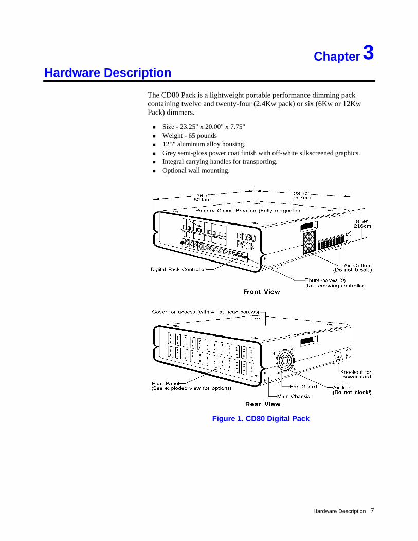
The CD80 Pack is a lightweight portable performance dimming pack containing twelve and twenty-four (2.4Kw pack) or six (6Kw or 12Kw Pack) dimmers.
Size - 23.25" x 20.00" x 7.75" Weight - 65 pounds 125" aluminum alloy housing. Grey semi-gloss power coat finish with off-white silkscreened graphics. Integral carrying handles for transporting. Optional wall mounting.
3
Figure 1. CD80 Digital Pack
Hardware Description
The CD80 Pack chassis consists of a main structural chassis (bottom housing and front panel), a removable top, and an interchangeable rear connector panel. The heavy gauge structural panels create a rugged container even though assembled with only four pieces.
The main structural chassis consists of the bottom housing and front panel fastened rigidly together. The front panel is recessed to protect the breakers and PCB face panel components.
The front panel, constructed of .090 thick aluminum alloy, contains U.L. listed circuit breakers and a slot for the plug-in printed circuit board module.
The bottom housing, constructed of .125 thick aluminum alloy, supports a heat sink subassembly (mounting the solid state relays and an overheat thermostat), a fan, a fan guard, a torroidal choke subassembly (with chokes solidly mounted in a "clamshell" Lexan retaining channel), and a power-in knock-out, provided for customer removal for terminal wiring. The rear panel is attached to the main structural chassis and recessed to protect the connector faces. Four large diameter feet, approximately 3/4" high, are at-tached to the underside of the bottom housing and existing feet mount holes are accessible for easy wall mounting.
The rear connector panel, constructed of .090 thick aluminum alloy, is manufactured in four customer options:
Pin connectors Twist lock GTL connectors (2.4 and 6Kw units only). Straight blade (Duplex) connectors (on 2.4Kw only)
The top cover, constructed of .125 aluminum alloy, fastens to the main chassis by four screws, and allows easy access for servicing. Recessed handles are integrated into the top housing for easy one man carry capability. Instruction labels are affixed to the underside of the top cover and a warning label..., "Disconnect power before removing top"...attached to the top of the cover.
Chassis
Hardware Description 9
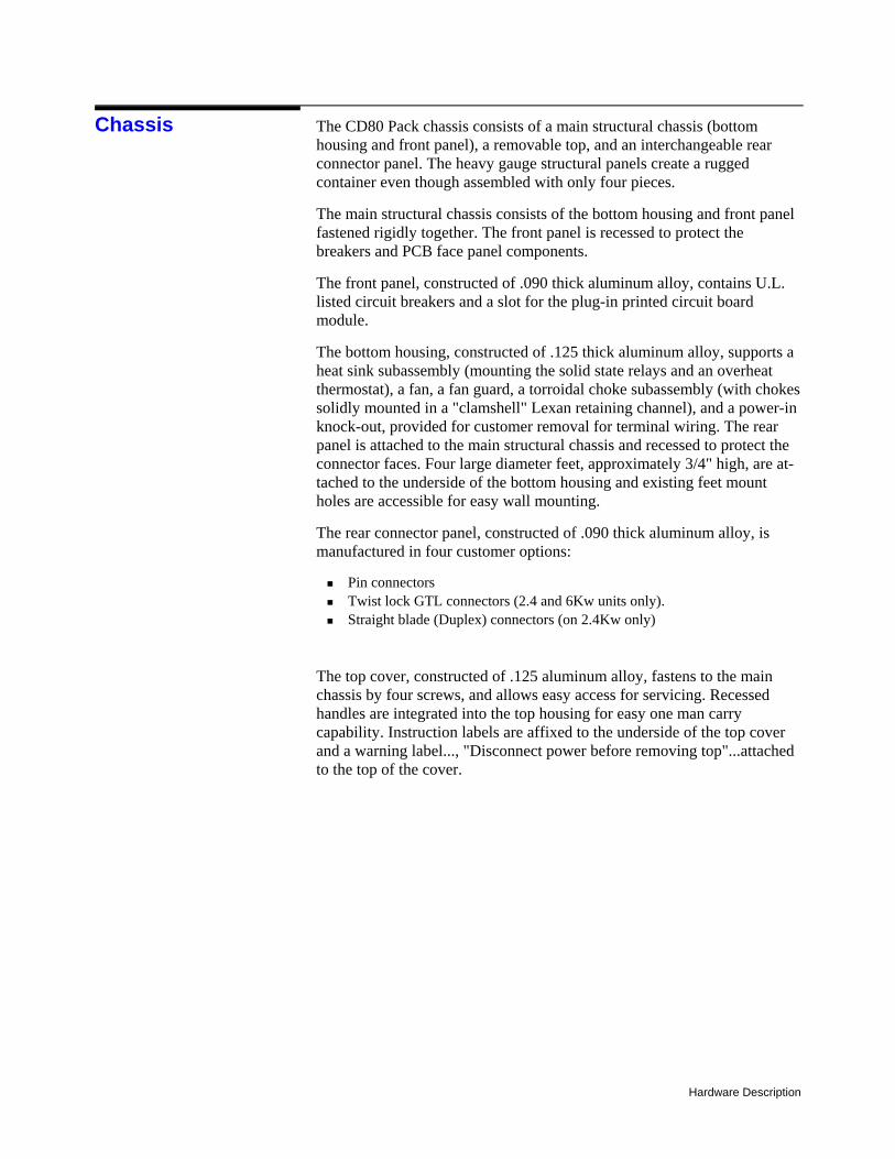
The plug-in controller, accessible on the front panel of the CD80 Pack, is made of a face plate and control card. The Control Module contains all necessary indicators and control electronics, allowing rapid interchange of active components in the field without the need for calibration or adjustment.
The following functions and indicators are on the Control Module face plate:
Three Power Indicators (green) - show when each power phase is present. Protocol Indicators (freen) - show which DMX512input is currently being
used. OverTemp Indicator (red) - On when heat sink temperatures exceed +85°C.
The pack will shut down when this function is activated. An alternate action "Panic" switch with LED indicator - to turn all dimmers
ON full. Push this switch again to return all dimmers to normal operation. (Dimmers are selected for panic via dip switches on the controller card).
12 or 24 alternate action ON/NORMAL (override) push-button switches let you turn any dimmer ON without a console. Each switch has an associated LED representing the output level of the dimmer.
Menu navigation buttons LED display DMX-A, DMX-B, DMX thru XLR connectors
Digital Controller
Figure 2. CD80 Digital Pack Controller
Control Module Front Panel
Hardware Description
The CD80 Digital Pack Controller will accept DMX512 digital dimmer protocol.
The Controller electronics contains all of the electronics required to detect input signal type, decode the incoming signal, and produce 12 or 24 phase synchronized pulse width modulated control signals to drive the SSRs.
The electronics are powered from a power supply connected to the phase A power source. The phase B and phase C power sources are used for phase reference only.
The following circuit and thermal elements in the bottom housing and front panel serve to control and dissipate power in the CD80 Pack:
One SSR for each dimmer, rated appropriately for the dimmer power rating, are mounted on a common 18" long heat sink anchored to the bottom housing. Each SSR is field replaceable.
One torroidal choke for each dimmer is mounted in a common assembly adjacent to the heat sink.
One primary, fully magnetic circuit breaker for each dimmer is mounted to the front panel and provides for protection of individual dimmers.
A fan mounted on the positive pressure side of the heat sink provides ap-proximately 70 CFM (derated) of cooling air through the enclosure.
A phase changing/terminal block assembly on the bottom housing (except 12Kw packs) provides termination of either 3 phase 4-wire plus ground 120/208VAC 80 AMPS, or single phase 3-wire plug ground 120/240VAC 120 AMPS.
The following controllers are available for retrofitting and spares:
76474 - 6 channel Digital Pack Controller (for 6.0 & 12.0Kw packs) (Includes cable adaptors) 76475 - 12 channel Digital Pack Controller and retrofit kit 76476 – 24 channel Digital Pack Controller and retrofit kit
The 24 channel Digital Pack Controller cannot be retrofitted into any existing CD80 packs. Cat. #76470 contains only a 24 channel Digital Pack Controller. The 12 channel Digital Pack Controller is a direct replacement for the Multiplexed Analog Pack Controller (part #3-258358-010) and the Discreet Analog Pack Controller (part #3-258362-010). Cat. #76471 contains a 12 channel Digital Pack Controller and the necessary items for retrofitting older CD80 packs.
A variety of input power connectors can be custom mounted in the CD80 pack if required. Packs using special input connectors may not carry CSA approval or UL listing. Please contact your sales representative for details.
Controller Electronics
Power Control and Cooling Assemblies
Dimmer Types
Input Power Connectors
Installation 11
Chapter Installation
Before installing your CD80 Pack, you should carefully consider the environment in which the equipment is to be installed, the power feeding the equipment, and the required conduit and/or cable runs.
To maximize equipment life, and minimize the chance of failures, the following environmental requirements should be met:
Temperature -- 40°C (104°F). Humidity -- 5%-80% relative humidity maximum, no condensation.
Dimmer pack efficiency is at least 95%. Since the remainder of the energy is dissipated as heat, they should be installed in a room with adequate ventilation to dissipate a heat load equivalent to 5% of the maximum load the dimmer racks will handle.
2.4Kw and 6Kw CD80 Digital Dimmer Packs can be powered by three phase or single phase power. 12Kw Digital Dimmer packs must be powered by three phase power.
Three Phase Power Requirements 12 circuit 2.4Kw Pack - 120/208VAC, 80 Amps, 4-wire plus ground. 24 circuit 2.4Kw Pack - 120/208VAC, 160 Amps, 4-wire plus ground 6Kw Pack - 120/208VAC, 100 Amps 4-wire plus ground 12Kw Pack - 120/208VAC, 200 Amps, 4-wire plus ground
Single Phase Power Requirements 2.4Kw Pack - 120VAC, 120 Amps, 3-wire plus ground 6Kw Pack - 120VAC, 150 Amps 3-wire plus ground 12Kw Pack - Single phase operation is not allowed
Do not install this equipment with power applied. Make sure that your incoming power is disconnected before proceeding. Do not provide 220VAC power to a 120VAC pack, as damage may result.
The CD80 Pack may be placed on any flat surface for normal operation. You may stack up to 8 units vertically. Do not place more than 2 units side to side unless there is at least 24 inches between packs. Otherwise, the hot
4
Preparation
EnvironmentalConsiderations
Caution
Power Requirements
Warning
Plan Pack Positioning
Installation
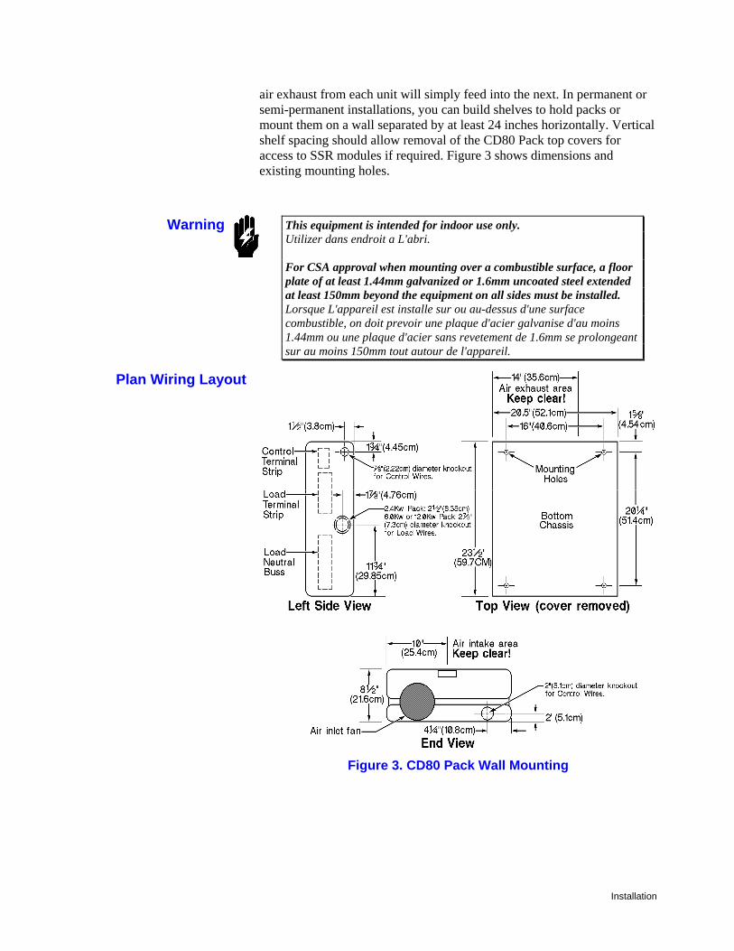
air exhaust from each unit will simply feed into the next. In permanent or semi-permanent installations, you can build shelves to hold packs or mount them on a wall separated by at least 24 inches horizontally. Vertical shelf spacing should allow removal of the CD80 Pack top covers for access to SSR modules if required. Figure 3 shows dimensions and existing mounting holes.
This equipment is intended for indoor use only. Utilizer dans endroit a L'abri. For CSA approval when mounting over a combustible surface, a floor plate of at least 1.44mm galvanized or 1.6mm uncoated steel extended at least 150mm beyond the equipment on all sides must be installed. Lorsque L'appareil est installe sur ou au-dessus d'une surface combustible, on doit prevoir une plaque d'acier galvanise d'au moins 1.44mm ou une plaque d'acier sans revetement de 1.6mm se prolongeant sur au moins 150mm tout autour de l'appareil.
Warning
Figure 3. CD80 Pack Wall Mounting
Plan Wiring Layout
Installation 13
Figure 3 shows the allowed entry areas for the various types of wiring. When installing portable packs, all connections are external.
When you are planning a hookup for a portable system you should avoid running control and load wires parallel to each other. The radio frequency noise produced by the load wiring may cause disruption to the control signal.
Do not run power feed or load wires in the same conduit or wireway as control wiring. Do not run wiring from other unrelated equipment in the same conduit with CD80 wiring. Do not run wiring in ways other than shown on system riser diagram. CD80 systems are designed to be installed in a specific manner. Do not substitute plastic conduit for metal where conduit is called for. Metal conduit acts as a ground and shield. Do not substitute shielded wiring for unshielded wiring or conduit. Changes in transmission line capacitance can cause problems with the control signals.
Caution

Installation
Once you have determined that all required conditions for the installation will be met, you can install the pack.
Install the dimmer pack and run conduit as required.
1. Unpack the pack. 2. Make sure that any conduit work which will be covered up is completed. 3. Set or fasten pack in place as planned. If you are mounting pack on the wall,
make sure that the fan is at the bottom of the unit as mounted. 5. Cut required conduit holes and install conduit. 6. Vacuum out any metal chips resulting from making conduit holes.
You must set the phase selector plug inside the pack to the same phase type (see below).
The phase changing terminal assembly (consisting of a terminal block and a connector pair assembly) provides termination for a 3-phase 4-wire 240/208VAC 80 AMP power source or a single phase 3-wire 120/240VAC 120 AMP power source in 2.4Kw and 6Kw CD80 Packs.
Set for Single Phase Operation 1. Make sure power to the pack is OFF and
take the top cover OFF. 2. Plug the phase connector into the single
phase side of the phase receptacle. 3. Replace the top cover unless you still
need to connect power.
Set for Three Phase Operation (default)
1. Make sure power to the pack is OFF and take the top cover OFF.
2. Plug the phase connector into the three phase side of the phase receptacle.
3. Replace the top cover unless you still need to connect power.
Note: The CD80 Pack Controller auto-senses single-phase & three phase power input.
12Kw Packs are always operated with three phase power. Make sure that the Mode Switch 2 is set to OFF for any 12Kw packs. There is no phase change plug inside a 12Kw Pack.
Installation
Install Pack
Set Correct Phasing
Installation 15
Connect power to the pack by attaching your power leads to the power terminal block inside the pack. For portable packs, close the pack up after connecting power.
Connect the load wires by plugging them into the rear panel connectors.
These dimmer packs are designed and rated for use with incandescent or inductive loads only. Dimmer packs may be damaged if used with any other type of loads
CD80 Digital Dimmer Pack accepts control signals conforming to the DMX512 Dimmer Signal Specifications.
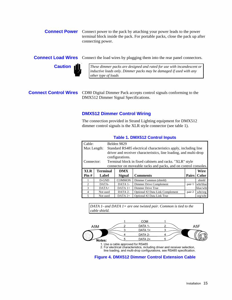
DMX512 Dimmer Control Wiring The connection provided in Strand Lighting equipment for DMX512 dimmer control signals is the XLR style connector (see table 1).
Table 1. DMX512 Control Inputs Cable: Belden 9829 Max Length: Standard RS485 electrical characteristics apply, including line
driver and receiver characteristics, line loading, and multi-drop configurations.
Connector: Terminal block in fixed cabinets and racks. "XLR" style connector on moveable racks and packs, and on control consoles.
XLR Pin #
TerminalLabel
DMX Signal
Comments
Pairs
Wire Color
1 D-GND COMMON Dimmer Common (shield) shield 2 DATA- DATA 1- Dimmer Drive Complement pair 1 wht/blue3 DATA+ DATA 1+ Dimmer Drive True blue/wht4 Not used DATA 2- Optional #2 Data Link Complement pair 2 wht/org5 Not used DATA 2+ Optional #2 Data Link True org/wht
DATA 1- and DATA 1+ are one twisted pair. Common is tied to the cable shield.
Connect Power
Connect Load Wires
Caution
Connect Control Wires
Figure 4. DMX512 Dimmer Control Extension Cable

Installation
Processor Setup 17
Chapter Processor Setup
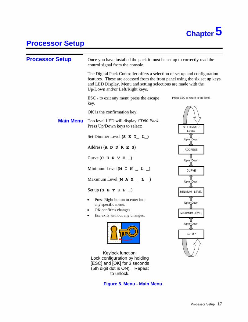
Once you have installed the pack it must be set up to correctly read the control signal from the console.
The Digital Pack Controller offers a selection of set up and configuration features. These are accessed from the front panel using the six set up keys and LED Display. Menu and setting selections are made with the Up/Down and/or Left/Right keys.
ESC - to exit any menu press the escape key.
OK is the confirmation key.
Top level LED will display CD80 Pack. Press Up/Down keys to select: Set Dimmer Level (S E T_ L_) Address (A D D R E S) Curve (C U R V E _) Minimum Level (M I N _ L _) Maximum Level (M A X _ L _) Set up (S E T U P _)
Figure 5. Menu - Main Menu
5
Processor Setup
Main Menu
• Press Right button to enter into any specific menu.
• OK confirms changes. • Esc exits without any changes.
Press ESC to return to top level.
SET DIMMER LEVEL
Up or Down
Up or Down
Up or Down
Up or Down
Up or Down
SETUP
MAXIMUM LEVEL
CURVE
MINIMUM LEVEL
ADDRESS
Keylock function: Lock configuration by holding [ESC] and [OK] for 3 seconds (5th digit dot is ON). Repeat
to unlock.
Processor Setup
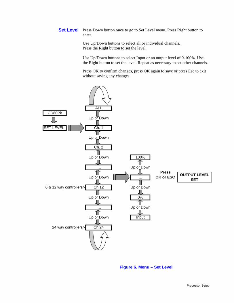
Press Down button once to go to Set Level menu. Press Right button to enter.
Use Up/Down buttons to select all or individual channels. Press the Right button to set the level. Use Up/Down buttons to select Input or an output level of 0-100%. Use the Right button to set the level. Repeat as necessary to set other channels.
Press OK to confirm changes, press OK again to save or press Esc to exit without saving any changes.
Figure 6. Menu – Set Level
Set Level
ALLCD80Pk
Up or Down
SET LEVEL Ch. 1
Up or Down
Ch. 2
Up or Down 100%
…. Up or DownPress
Up or Down … OK or ESC
6 & 12 way controllers> Ch.12 Up or Down
Up or Down 0%
…. Up or Down
Up or Down Input
24 way controllers> Ch.24
OUTPUT LEVEL SET
Processor Setup 19
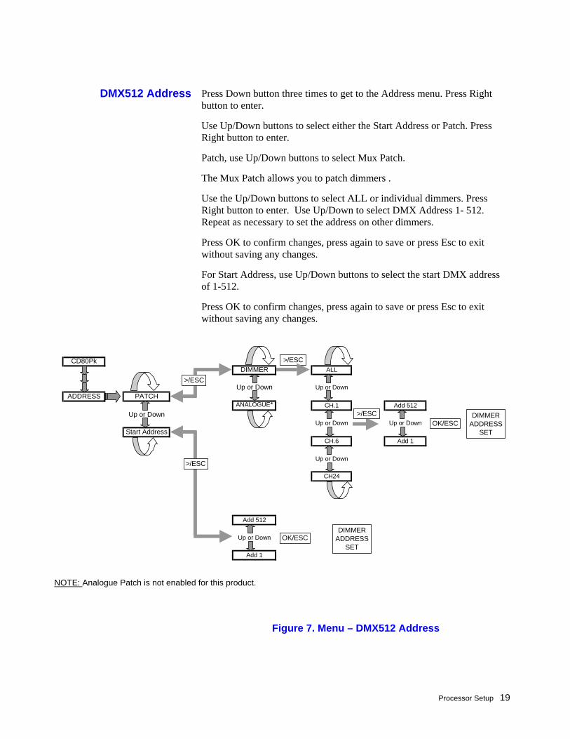
Press Down button three times to get to the Address menu. Press Right button to enter.
Use Up/Down buttons to select either the Start Address or Patch. Press Right button to enter.
Patch, use Up/Down buttons to select Mux Patch.
The Mux Patch allows you to patch dimmers .
Use the Up/Down buttons to select ALL or individual dimmers. Press Right button to enter. Use Up/Down to select DMX Address 1- 512. Repeat as necessary to set the address on other dimmers.
Press OK to confirm changes, press again to save or press Esc to exit without saving any changes.
For Start Address, use Up/Down buttons to select the start DMX address of 1-512.
Press OK to confirm changes, press again to save or press Esc to exit without saving any changes.
DMX512 Address
Figure 7. Menu – DMX512 Address
CD80PkDIMMER ALL
Up or Down Up or DownADDRESS PATCH
ANALOGUE* CH.1 Add 512Up or Down
Up or Down Up or DownStart Address
CH.6 Add 1
Up or Down
CH24
Add 512
Up or Down
Add 1
>/ESC
>/ESC
>/ESC
>/ESC
DIMMER ADDRESS
SETOK/ESC
DIMMER ADDRESS
SETOK/ESC
NOTE: Analogue Patch is not enabled for this product.
Processor Setup
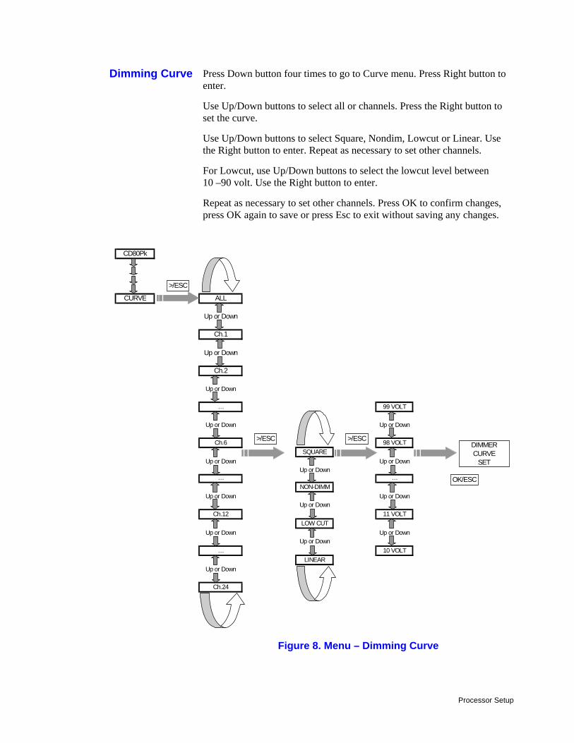
Press Down button four times to go to Curve menu. Press Right button to enter.
Use Up/Down buttons to select all or channels. Press the Right button to set the curve.
Use Up/Down buttons to select Square, Nondim, Lowcut or Linear. Use the Right button to enter. Repeat as necessary to set other channels.
For Lowcut, use Up/Down buttons to select the lowcut level between 10 –90 volt. Use the Right button to enter.
Repeat as necessary to set other channels. Press OK to confirm changes, press OK again to save or press Esc to exit without saving any changes.
Figure 8. Menu – Dimming Curve
Dimming Curve
CD80Pk
CURVE ALL
Up or Down
Ch.1
Up or Down
Ch.2
Up or Down
… 99 VOLT
Up or Down Up or Down
Ch.6 98 VOLTSQUARE
Up or Down Up or DownUp or Down
… …NON-DIMM
Up or Down Up or DownUp or Down
Ch.12 11 VOLTLOW CUT
Up or Down Up or DownUp or Down
… 10 VOLTLINEAR
Up or Down
Ch.24
DIMMERCURVE
SET
OK/ESC
>/ESC
>/ESC >/ESC
Processor Setup 21
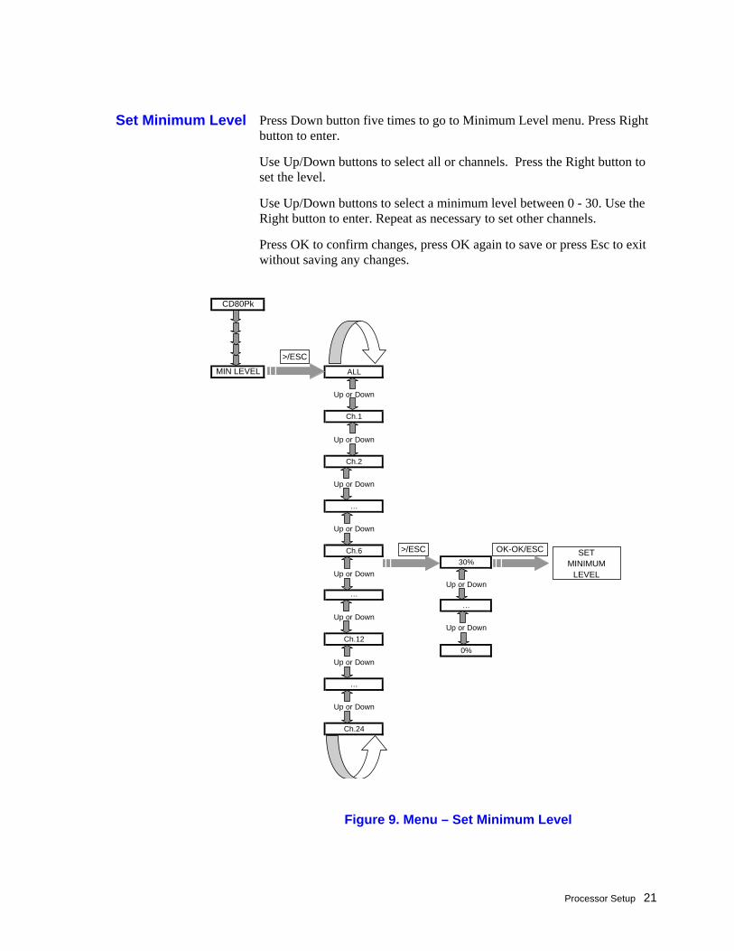
Press Down button five times to go to Minimum Level menu. Press Right button to enter.
Use Up/Down buttons to select all or channels. Press the Right button to set the level.
Use Up/Down buttons to select a minimum level between 0 - 30. Use the Right button to enter. Repeat as necessary to set other channels.
Press OK to confirm changes, press OK again to save or press Esc to exit without saving any changes.
Set Minimum Level
Figure 9. Menu – Set Minimum Level
CD80Pk
MIN LEVEL ALL
Up or Down
Ch.1
Up or Down
Ch.2
Up or Down
…
Up or Down
Ch.630%
Up or DownUp or Down
……
Up or DownUp or Down
Ch.120%
Up or Down
…
Up or Down
Ch.24
SET MINIMUM
LEVEL
OK-OK/ESC
>/ESC
>/ESC
Processor Setup
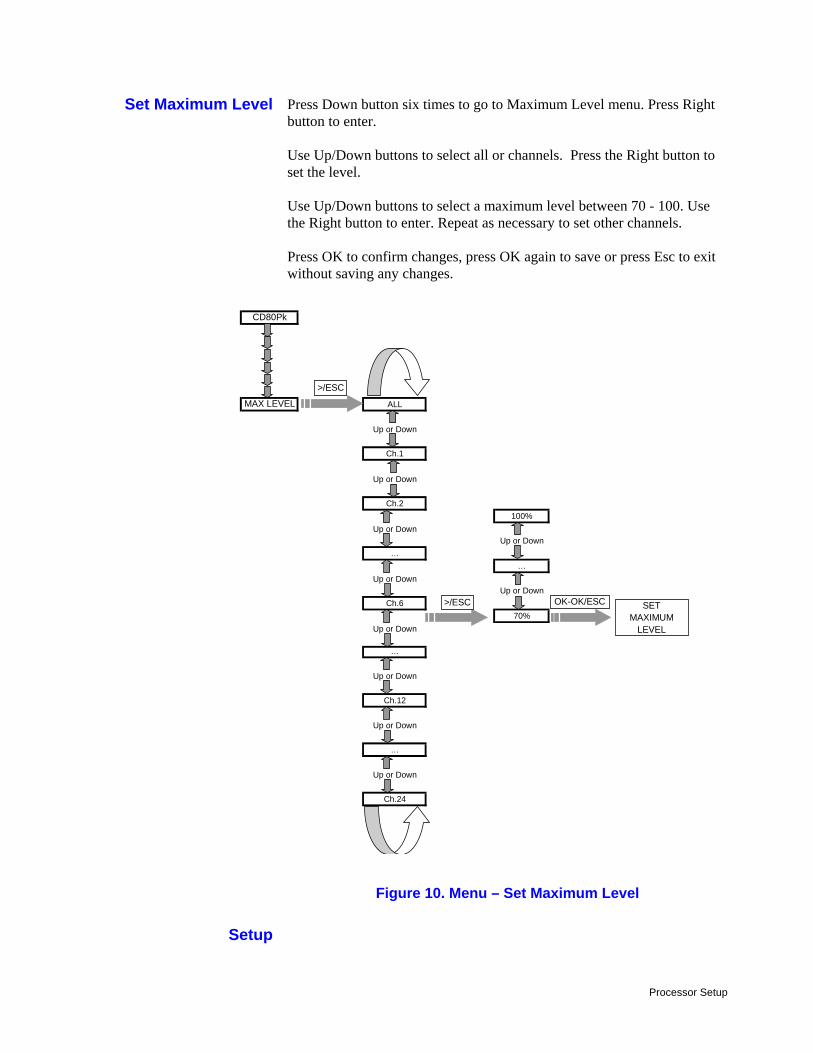
Press Down button six times to go to Maximum Level menu. Press Right button to enter. Use Up/Down buttons to select all or channels. Press the Right button to set the level. Use Up/Down buttons to select a maximum level between 70 - 100. Use the Right button to enter. Repeat as necessary to set other channels. Press OK to confirm changes, press OK again to save or press Esc to exit without saving any changes.
Figure 10. Menu – Set Maximum Level
Set Maximum Level
Setup
CD80Pk
MAX LEVEL ALL
Up or Down
Ch.1
Up or Down
Ch.2100%
Up or DownUp or Down
……
Up or DownUp or Down
Ch.670%
Up or Down
…
Up or Down
Ch.12
Up or Down
…
Up or Down
Ch.24
SET MAXIMUM
LEVEL
OK-OK/ESC
>/ESC
>/ESC
Processor Setup 23
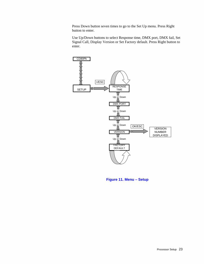
Press Down button seven times to go to the Set Up menu. Press Right button to enter.
Use Up/Down buttons to select Response time, DMX port, DMX fail, Set Signal Call, Display Version or Set Factory default. Press Right button to enter.
Figure 11. Menu – Setup
CD80Pk
SETUPRESPONSE
TIME
Up or Down
DMX PORT
Up or Down
DMX FAIL
Up or Down
VERSION
Up or Down
FACTORY DEFAULT
VERSIONNUMBER
DISPLAYED
OK/ESC
>/ESC
Processor Setup
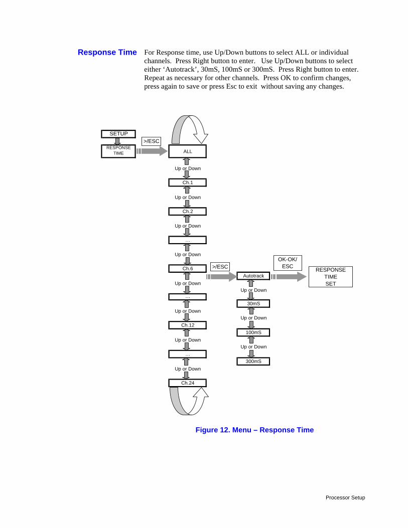
For Response time, use Up/Down buttons to select ALL or individual channels. Press Right button to enter. Use Up/Down buttons to select either ‘Autotrack’, 30mS, 100mS or 300mS. Press Right button to enter. Repeat as necessary for other channels. Press OK to confirm changes, press again to save or press Esc to exit without saving any changes.
Figure 12. Menu – Response Time
Response Time
SETUP
RESPONSE TIME ALL
Up or Down
Ch.1
Up or Down
Ch.2
Up or Down
…
Up or Down
Ch.6Autotrack
Up or DownUp or Down
…30mS
Up or DownUp or Down
Ch.12100mS
Up or DownUp or Down
…300mS
Up or Down
Ch.24
RESPONSE TIMESET
OK-OK/ ESC
>/ESC
>/ESC
Processor Setup 25
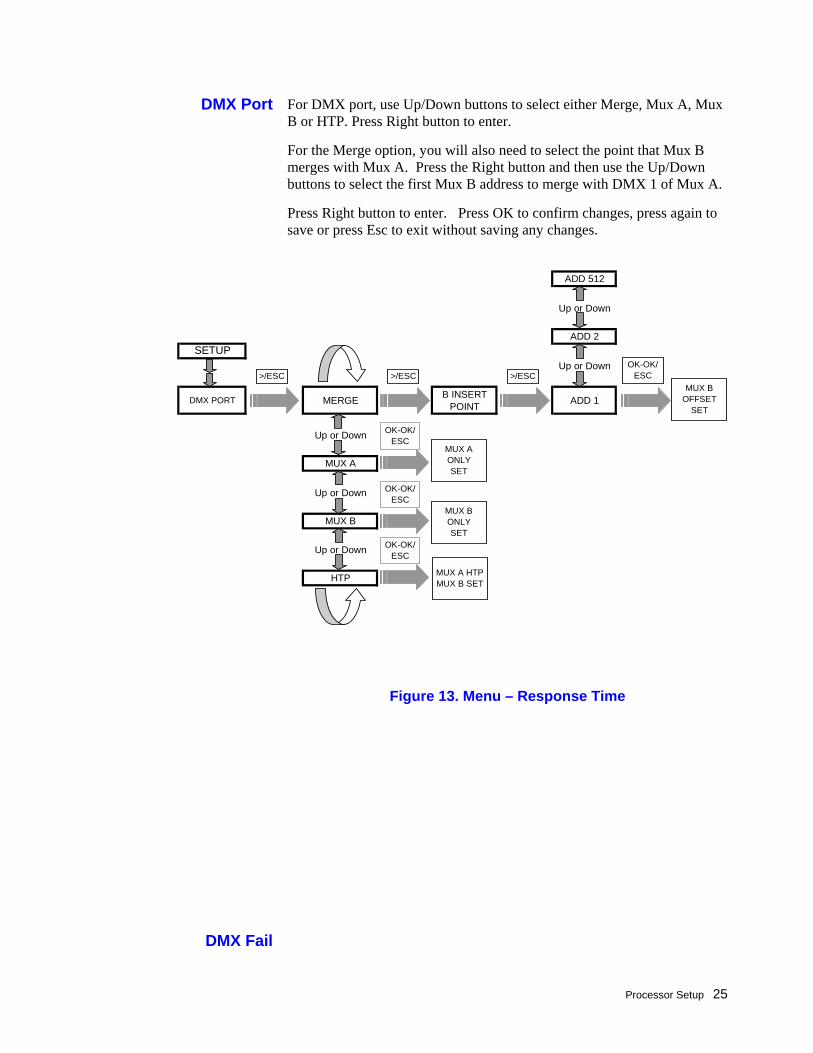
For DMX port, use Up/Down buttons to select either Merge, Mux A, Mux B or HTP. Press Right button to enter.
For the Merge option, you will also need to select the point that Mux B merges with Mux A. Press the Right button and then use the Up/Down buttons to select the first Mux B address to merge with DMX 1 of Mux A.
Press Right button to enter. Press OK to confirm changes, press again to save or press Esc to exit without saving any changes.
DMX Port
Figure 13. Menu – Response Time
DMX Fail
ADD 512
Up or Down
ADD 2SETUP
Up or Down
DMX PORT MERGE B INSERT POINT ADD 1
Up or Down
MUX A
Up or Down
MUX B
Up or Down
HTP
MUX BOFFSET
SET
>/ESCOK-OK/
ESC>/ESC >/ESC
OK-OK/ ESC
OK-OK/ ESC
OK-OK/ ESC
MUX A ONLYSET
MUX BONLYSET
MUX A HTP MUX B SET
Processor Setup
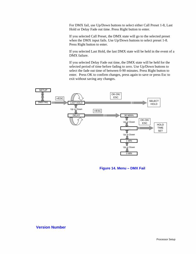
For DMX fail, use Up/Down buttons to select either Call Preset 1-8, Last Hold or Delay Fade out time. Press Right button to enter.
If you selected Call Preset, the DMX state will go to the selected preset when the DMX input fails. Use Up/Down buttons to select preset 1-8. Press Right button to enter.
If you selected Last Hold, the last DMX state will be held in the event of a DMX failure.
If you selected Delay Fade out time, the DMX state will be held for the selected period of time before fading to zero. Use Up/Down buttons to select the fade out time of between 0-90 minutes. Press Right button to enter. Press OK to confirm changes, press again to save or press Esc to exit without saving any changes.
Figure 14. Menu – DMX Fail
Version Number
SETUP
DMX FAIL LAST HOLD
Up or Down
DELAY 90 MIN%
Up or Down
….
Up or Down
1 MIN
Up or Down
0 MIN
SELECTHOLD
OK-OK/ ESC>/ESC
>/ESC
OK-OK/ ESC HOLD
TIMESET
Processor Setup 27
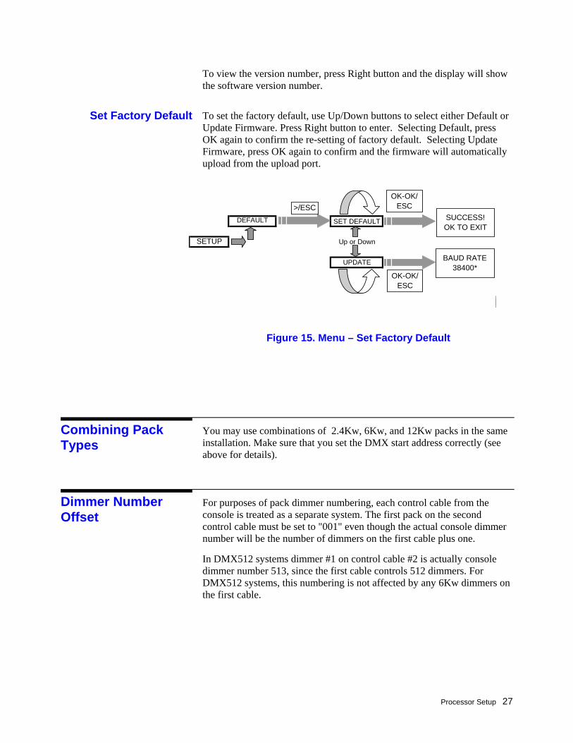
To view the version number, press Right button and the display will show the software version number.
To set the factory default, use Up/Down buttons to select either Default or Update Firmware. Press Right button to enter. Selecting Default, press OK again to confirm the re-setting of factory default. Selecting Update Firmware, press OK again to confirm and the firmware will automatically upload from the upload port.
You may use combinations of 2.4Kw, 6Kw, and 12Kw packs in the same installation. Make sure that you set the DMX start address correctly (see above for details).
For purposes of pack dimmer numbering, each control cable from the console is treated as a separate system. The first pack on the second control cable must be set to "001" even though the actual console dimmer number will be the number of dimmers on the first cable plus one.
In DMX512 systems dimmer #1 on control cable #2 is actually console dimmer number 513, since the first cable controls 512 dimmers. For DMX512 systems, this numbering is not affected by any 6Kw dimmers on the first cable.
Set Factory Default
Figure 15. Menu – Set Factory Default
Combining Pack Types
Dimmer Number Offset
DEFAULT SET DEFAULT
SETUP Up or Down
UPDATE
SUCCESS! OK TO EXIT
OK-OK/ ESC>/ESC
OK-OK/ ESC
BAUD RATE38400*
Processor Setup
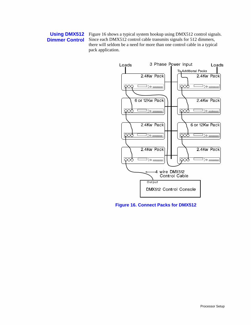
Figure 16 shows a typical system hookup using DMX512 control signals. Since each DMX512 control cable transmits signals for 512 dimmers, there will seldom be a need for more than one control cable in a typical pack application.
Using DMX512Dimmer Control
Figure 16. Connect Packs for DMX512
Processor Setup 29
If the SSR heat sink overheats, the OverTemp indicator will turn ON and the pack will shut down. This shows that air flow has been blocked or the fan has failed.
Electromagnetic circuit breakers protect the SSRs if there is a dead short, (defined as .02 ohms or less) across 40 feet of #14 AWG load wires. A short on any dimmer in the pack will trip the circuit breaker for the dimmer OFF. You can restore circuit operation by clearing the short and turning the circuit breaker back ON.
On 2.4Kw, 6Kw, and 12Kw packs you can check your load wiring for shorts by using the "hot Pocket" on the back of the pack. This receptacle is wired directly to the last circuit breaker (#6 on 6Kw or 12Kw dimmers and #12 on 2.4Kw dimmer) and connected in parallel to the "test outlet" pilot light.
On 2.4Kw dimmers this "hot pocket" is the 24th receptacle (the second receptacle for dimmer #12). You can convert the "hot pocket" to normal dimmer output by moving the power lead for receptacle 24 from the AC input terminal of SSR #12 to its output terminal.
On 6Kw and 12Kw packs, there is a seventh receptacle wired directly to circuit breaker #6.
This feature also aids in trouble shooting by isolating faults to either the user load or the CD80 Pack.
Dimmers attached to a CD80 Digital Pack can be turned ON and OFF locally by using either the PANIC switch or the individual ON/NORMAL push-buttons.
The alternate action PANIC switch lets you turn all dimmers in the pack ON if required.
Use a bent paper clip or other thin probe to press the PANIC switch ON. Press the switch again to return to normal dimmer control.
Set the dip switches located on the pack (SW1 for 12 channel packs. SW1 & SW2 for 24 channel packs) to ON position for panic.
Fault Protection
Hot Pocket
Local Dimmer Control
Dimmer Panic
Processor Setup
Each dimmer output can be switched ON using the ON/NORMAL push-button associated with the dimmer.
Press the required push-button to turn the associated dimmer ON. Press the push-button again to return the dimmer to normal dimmer control.
The 12 channel CD80 Digital Pack Controller (Cat. #76474) is a direct replacement for:
Original CD80 Digital Pack Controller (Cat. #76471)
CD80 Multiplexed Analog Pack Controller (part #3-258358-010)
CD80 Discreet Analog Pack Controller (part #3-358362-010)
It is very easy to retrofit a 12 channel Digital Pack Controller into an older CD80 pack to provide compatibility with a larger variety of control signals.
The 24 channel pack controller cannot be retrofitted into a 6 or 12 channel pack.
1. Make sure that power to the pack is OFF 2. Remove the old controller from the pack. 3. Install the new controller in the pack. 4. Turn power to the pack back ON. 5. Setup pack controller via processor menus (see page 19 for details).
ON/NORMAL Push-buttons
Retrofitting an Analog Pack
Basic Trouble-shooting 31
Chapter Basic Trouble-shooting
This chapter provides basic trouble-shooting procedures for the CD80 Digital Pack Controller. It does not provide comprehensive maintenance data, but allows you to solve simple problems which may occur, and helps to provide Strand Lighting with initial data when these procedures are not effective.
For best system operation, do a routine check and cleaning once each year unless the operating environment is unusually harsh or dirty. Please consult Strand Lighting field Service if you are in doubt about the frequency of maintenance required for your system. Service and maintenance operations other than this cleaning are seldom required. In case of problems, and in order to save time and aggravation, follow the procedures outlined here before calling Strand Lighting. Observe what happens at each step. These steps answer the first questions a Strand Lighting Service Representative will ask. The person actually doing the tests should call Strand Lighting in order to avoid confusion and misunderstanding.
Each section of this chapter describes a possible failure mode and actions to be taken. If all actions fail, please call the appropriate Strand Lighting office.
The CD80 Digital Pack has been designed to be serviced easily and quickly by the customer.
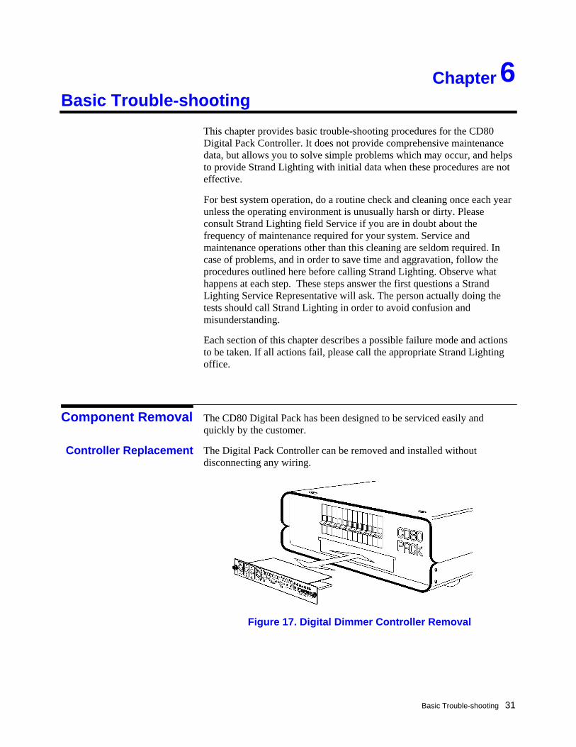
The Digital Pack Controller can be removed and installed without disconnecting any wiring.
6
Component Removal
Controller Replacement
Figure 17. Digital Dimmer Controller Removal
Basic Trouble-shooting
Removing the Controller 1. Turn power to the dimmer pack OFF. 2. Loosen two thumbscrews (on opposite ends of the controller). 3. Pull on the thumbscrews to remove the controller.
Installing the Controller 1. Turn power to the dimmer pack OFF. 2. Line the controller up with guides on each side of the slot. 3. Slide the module in carefully until it touches the connector in the pack. 4. Firmly seat the controller by pressing on both ends of the module.
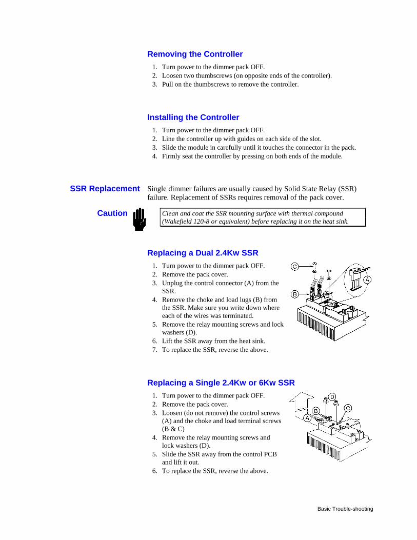
Single dimmer failures are usually caused by Solid State Relay (SSR) failure. Replacement of SSRs requires removal of the pack cover.
Clean and coat the SSR mounting surface with thermal compound (Wakefield 120-8 or equivalent) before replacing it on the heat sink.
Replacing a Dual 2.4Kw SSR 1. Turn power to the dimmer pack OFF. 2. Remove the pack cover. 3. Unplug the control connector (A) from the
SSR. 4. Remove the choke and load lugs (B) from
the SSR. Make sure you write down where each of the wires was terminated.
5. Remove the relay mounting screws and lock washers (D).
6. Lift the SSR away from the heat sink. 7. To replace the SSR, reverse the above.
Replacing a Single 2.4Kw or 6Kw SSR 1. Turn power to the dimmer pack OFF. 2. Remove the pack cover. 3. Loosen (do not remove) the control screws
(A) and the choke and load terminal screws (B & C)
4. Remove the relay mounting screws and lock washers (D).
5. Slide the SSR away from the control PCB and lift it out.
6. To replace the SSR, reverse the above.
SSR Replacement
Caution
Basic Trouble-shooting 33
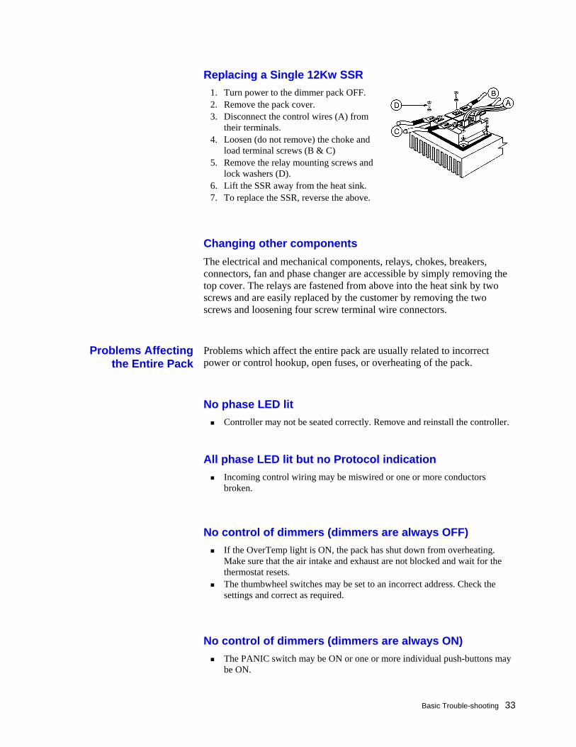
Replacing a Single 12Kw SSR 1. Turn power to the dimmer pack OFF. 2. Remove the pack cover. 3. Disconnect the control wires (A) from
their terminals. 4. Loosen (do not remove) the choke and
load terminal screws (B & C) 5. Remove the relay mounting screws and
lock washers (D). 6. Lift the SSR away from the heat sink. 7. To replace the SSR, reverse the above.
Changing other components The electrical and mechanical components, relays, chokes, breakers, connectors, fan and phase changer are accessible by simply removing the top cover. The relays are fastened from above into the heat sink by two screws and are easily replaced by the customer by removing the two screws and loosening four screw terminal wire connectors.
Problems which affect the entire pack are usually related to incorrect power or control hookup, open fuses, or overheating of the pack.
No phase LED lit Controller may not be seated correctly. Remove and reinstall the controller.
All phase LED lit but no Protocol indication Incoming control wiring may be miswired or one or more conductors
broken.
No control of dimmers (dimmers are always OFF)
If the OverTemp light is ON, the pack has shut down from overheating. Make sure that the air intake and exhaust are not blocked and wait for the thermostat resets.
The thumbwheel switches may be set to an incorrect address. Check the settings and correct as required.
No control of dimmers (dimmers are always ON) The PANIC switch may be ON or one or more individual push-buttons may
be ON.
Problems Affectingthe Entire Pack
Basic Trouble-shooting
Problems which are confined to a single phase are usually related to Controller problems or to the dimmer pack being incorrectly set up for the type of power in use.
Four consecutively numbered dimmers will not go ON The power feed for the phase may be OFF or not connected. The control module may be incorrectly inserted. Remove it and carefully re-
insert it into the dimmer pack. One or more output control circuits may have failed. Swap the Controller
with a known good spare. If the problem goes away, return the defective Controller to Strand Lighting for repair.
One or more dimmers on the same phase do not come up to full or do not track correctly
The phase change switch may be incorrectly set. Make sure that the pack is set up for the type of AC power you are using.
One or more output control circuits may be defective. Replace the defective Controller with a spare and return the defective unit to Strand Lighting for repair.
Problems Confined to aSingle Phase
Basic Trouble-shooting 35
Problems relating to individual dimmers are due to one of the following:
Dimmer Circuit Breaker is OFF Burned out lamp in fixture. Defective or disconnected load wiring. Defective Controller module. Defective discreet analog control wiring. Defective SSR, circuit breaker, or choke (probably the SSR).
Check for a load wiring problem or burned out lamp by turning the ON/NORMAL switch for the dimmer ON or by moving the suspect load to a known good dimmer. If the problem remains, repair the problem in the load circuit or lamp.
Check for a defective Controller module by swapping it with a known good unit from another pack. Make sure that the Mode switches are set the same way before replacing the Controller module. If the problem goes away with the new module, replace the defective Controller module with a spare and return the defective unit to Strand Lighting for repair.
Check for a defective SSR, choke, or circuit breaker by checking the voltage at the circuit breaker output, choke output, and SSR output with the dimmer ON. The component with an input but no output is defective. Replace the defective component.
If the dimmer works from the console (protocol input) but not from the discreet analog input, there is a problem in the discreet analog circuitry, probably external to the pack.
Individual DimmerProblems

Basic Trouble-shooting
Periodic Maintenance 37
Chapter Periodic Maintenance
Periodic Maintenance should be done every six (6) to twelve (12) months, depending on the environmental conditions. Although a detailed discussion of this procedure is beyond the scope of this manual, basic checklists are provided to show what is involved. Users wishing to do these procedures on their own should consult Strand Lighting Field Service.
1. Turn power to the dimmer pack OFF. 2. Inspect the dimmer pack for loose connections, build-up of dust, and (for
permanent or semi-permanent installations) placement of obstructions around it which may impede air flow. Tighten any loose connections found at this time.
3. Vacuum out any excessive dust build-up in the dimmer pack while power to the pack is shut down.
4. Remove the Control Module from the pack, dust it off with a soft natural bristle brush, and clean its edge connectors with a mixture of 70% denatured alcohol and 30% distilled water (or other cleaning compound intended for gold edge connectors).
5. Exercise all circuit breakers by turning them ON and OFF several times. The arc produced when the circuit breakers engage and disengage will clean corrosion and dust off of the contacts.
For best effect the lights for the dimmers should be ON when you do this.
6. Replace Control Module. 7. Turn power to the system ON and verify proper functioning.
7
Periodic Maintenance
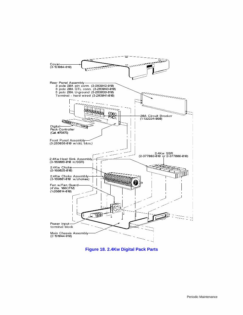
Figure 18. 2.4Kw Digital Pack Parts
Periodic Maintenance 39
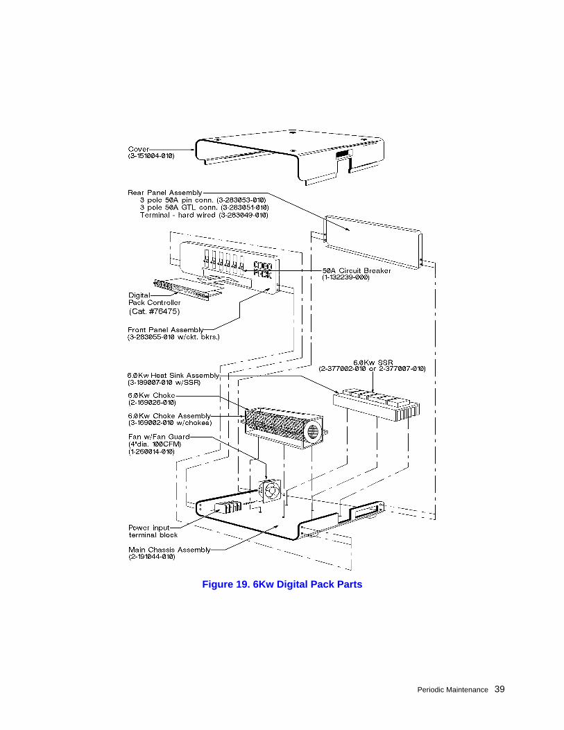
Figure 19. 6Kw Digital Pack Parts
Periodic Maintenance
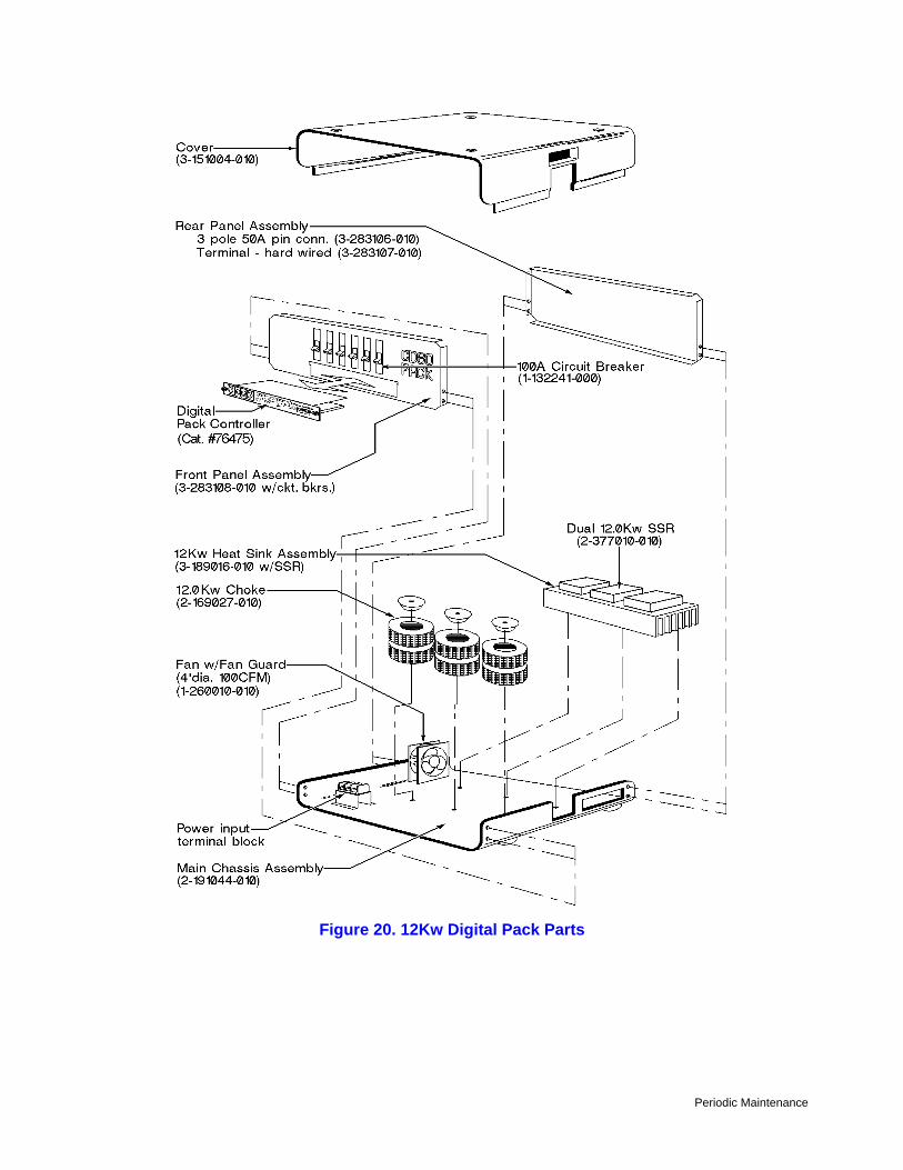
Figure 20. 12Kw Digital Pack Parts

Periodic Maintenance 41