Embed Size (px)
Citation preview
Dr. Hao ZhengComp Sci & Eng
U of South Florida
CDA 4253 FPGA System DesignFinite State Machines
2
Required Reading
P. Chu, FPGA Prototyping by VHDL ExamplesChapter 5, 6
3
Datapath vs. Controller
4
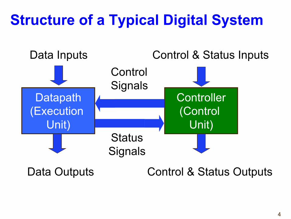
Structure of a Typical Digital System
Datapath(Execution
Unit)
Controller(Control
Unit)
Data Inputs
Data Outputs
Control & Status Inputs
Control & Status Outputs
Control Signals
StatusSignals
5
Datapath (Execution Unit)
→Manipulates and processes data.→Performs arithmetic and logic operations,
shifting/rotating, and other data-processing tasks.→Is composed of registers, multiplexers, adders,
decoders, comparators, ALUs, gates, etc.→Provides all necessary resources and
interconnects among them to perform specified task.→Interprets control signals from the controller and
generates status signals for the controller.
6
Controller (Control Unit)
➺ Controls data movement in the datapath by switching multiplexers and enabling or disabling resources
Example: enable signals for registersExample: select signals for muxes
➺ Provides signals to activate various processing tasks in the datapath, i.e. +, -, or *, ...
➺ Determines the sequence of operations performed by the datapath.
➺ Follows some ‘program’ or schedule.
7
Programmable vs. Non-Programmable Controller➺ Controller can be programmable or non-programmable➺ Programmable→ Has a program counter which points to next instruction→ Instructions are stored in a RAM or ROM→Microprocessor is an example of programmable
controller➺ Non-Programmable→ Once designed, implements the same functionality→ Another term is a “hardwired state machine,” or “hardwired FSM,” or “hardwired instructions”
→ In this course we will be focusing on non-programmable controllers.
8
Finite State Machines
➺ Controllers can be described as Finite State Machines (FSMs)→ counters and shift registers are FSMs
➺ Finite State Machines can be represented using→ State Diagrams and State Tables - suitable for simple
controllers with a relatively few inputs and outputs→ Algorithmic State Machine (ASM) ChartsWill be skipped as it is equivalent to state diagrams.
➺ All of these descriptions can be easily translated to the corresponding synthesizable VHDL code
Design Process
9
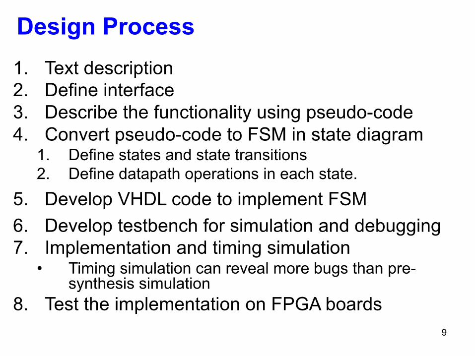
1. Text description2. Define interface3. Describe the functionality using pseudo-code4. Convert pseudo-code to FSM in state diagram
1. Define states and state transitions2. Define datapath operations in each state.
5. Develop VHDL code to implement FSM6. Develop testbench for simulation and debugging7. Implementation and timing simulation
• Timing simulation can reveal more bugs than pre-synthesis simulation
8. Test the implementation on FPGA boards
10
Finite State MachinesRefresher
11
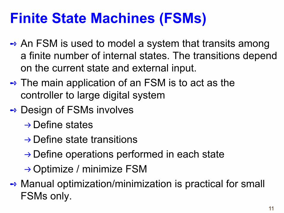
Finite State Machines (FSMs)➺ An FSM is used to model a system that transits among
a finite number of internal states. The transitions depend on the current state and external input.
➺ The main application of an FSM is to act as the controller to large digital system
➺ Design of FSMs involves→Define states→Define state transitions→Define operations performed in each state→Optimize / minimize FSM
➺ Manual optimization/minimization is practical for small FSMs only.
12
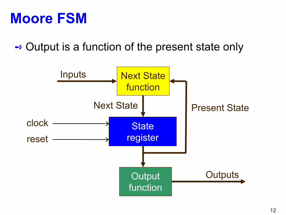
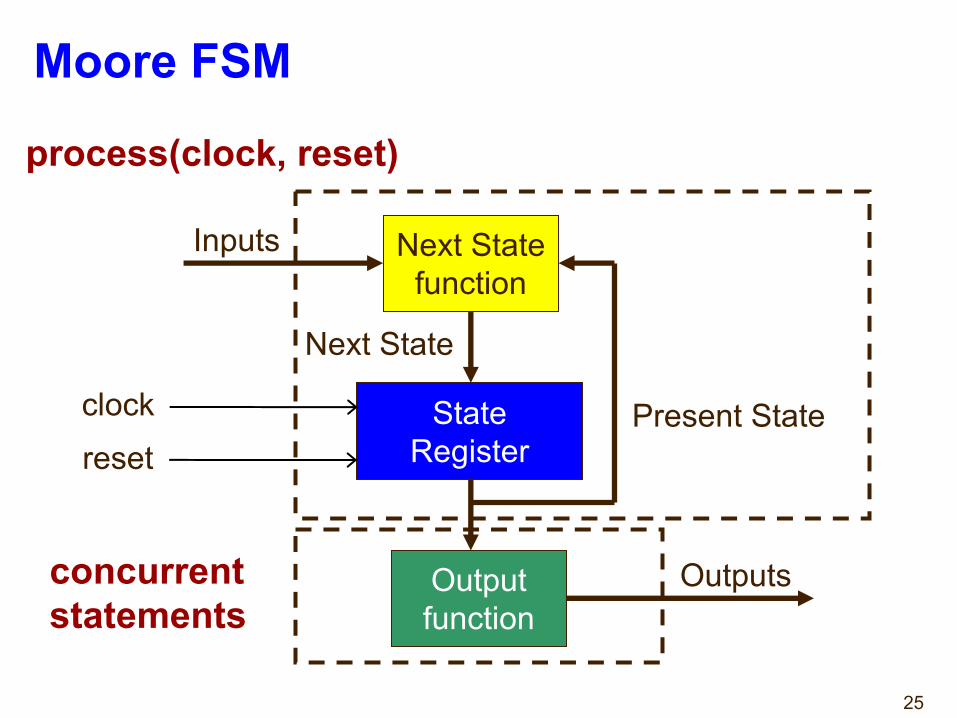
Moore FSM
➺ Output is a function of the present state only
Stateregister
Next Statefunction
Outputfunction
Inputs
Present StateNext State
Outputs
clockreset
13
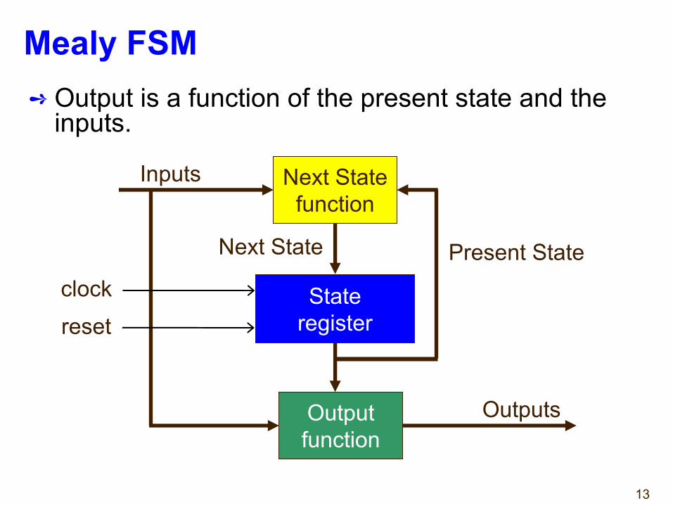
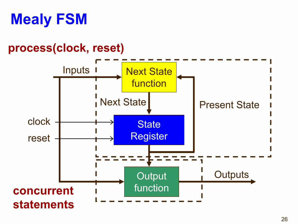
Mealy FSM➺ Output is a function of the present state and the
inputs.
Next Statefunction
Outputfunction
Inputs
Present StateNext State
Outputs
Stateregister
clockreset
14
State Diagrams
15
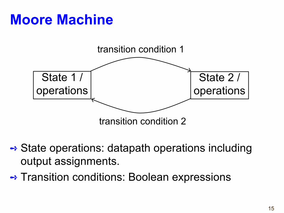
Moore Machine
➺ State operations: datapath operations including output assignments.
➺ Transition conditions: Boolean expressions
transition condition 1
transition condition 2
State 1 /operations
State 2 /operations
16
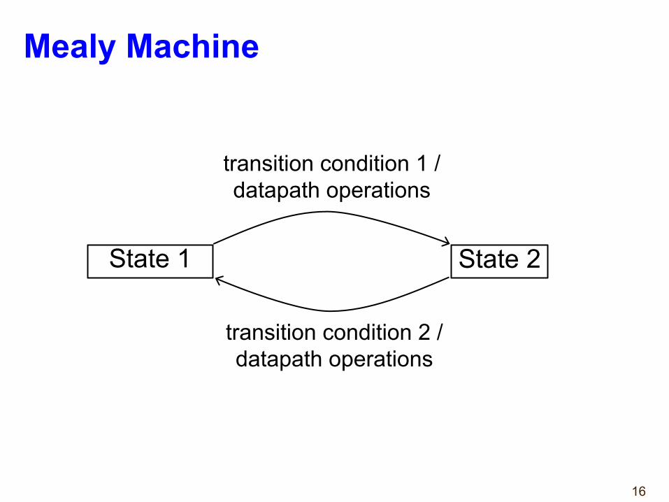
Mealy Machine
transition condition 1 /datapath operations
transition condition 2 /datapath operations
State 1 State 2
17
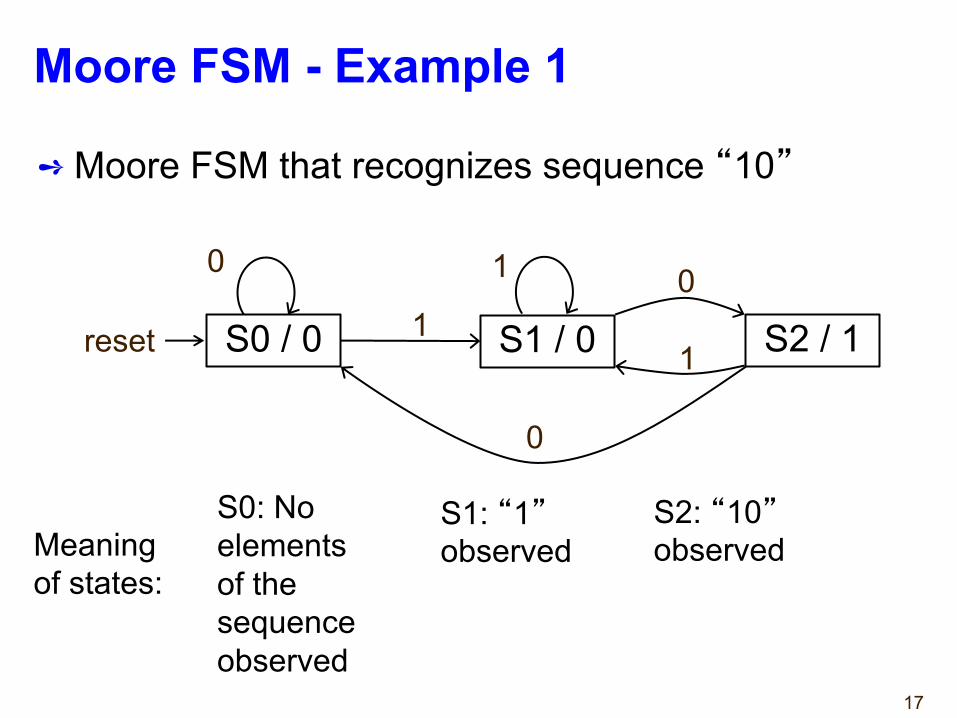
Moore FSM - Example 1
➺ Moore FSM that recognizes sequence “10”
reset
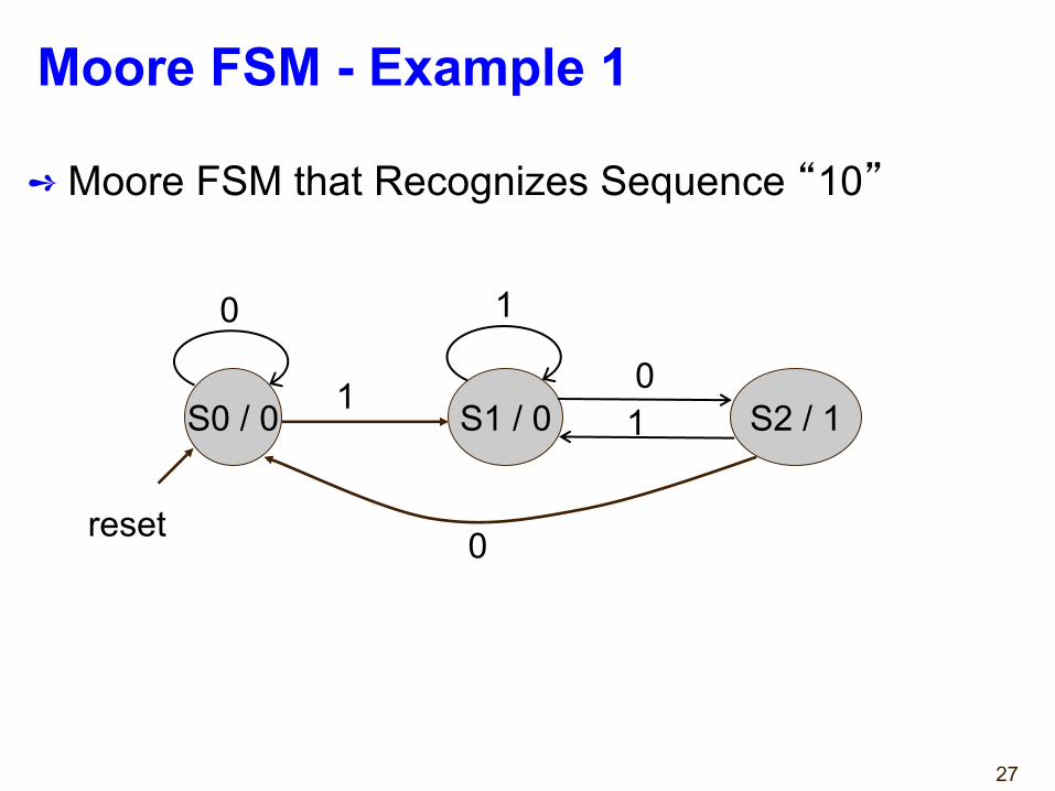
Meaning of states:
S0: No elements of the sequenceobserved
S1: “1”observed
S2: “10”observed
S0 / 0 S1 / 0 S2 / 11
01
0
0 1
18
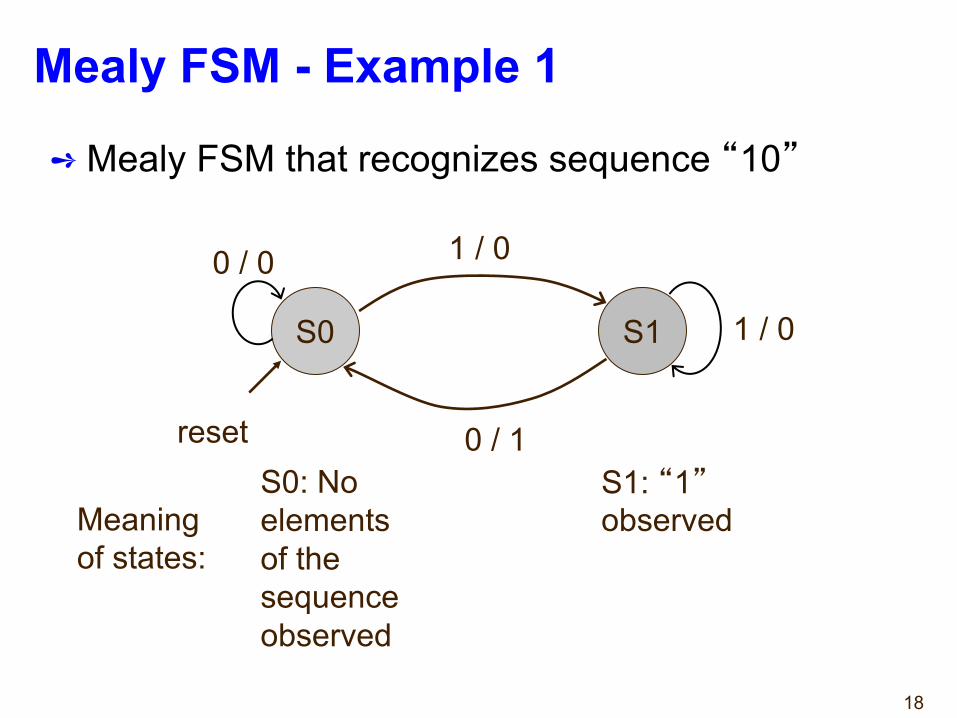
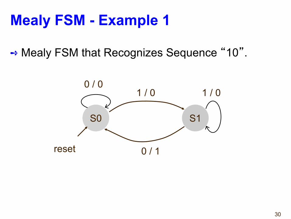
Mealy FSM - Example 1
➺ Mealy FSM that recognizes sequence “10”
S0 S1
0 / 0 1 / 0
1 / 0
0 / 1reset
Meaning of states:
S0: No elements of the sequenceobserved
S1: “1”observed
19
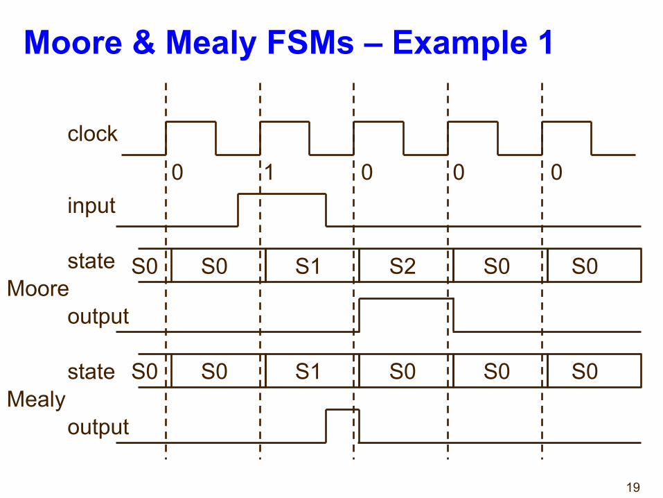
Moore & Mealy FSMs – Example 1
clock
input
Moore
Mealy
0 1 0 0 0
S0 S0 S1 S2 S0 S0
S0 S0 S1 S0 S0 S0
state
output
state
output
20
Moore vs. Mealy FSM (1)➺ Moore and Mealy FSMs are functionally equivalent.→ Equivalent Mealy FSM can be derived from Moore FSM
and vice versa.➺ Mealy FSM has richer description and usually
requires less number of states→ Smaller circuit area.
21
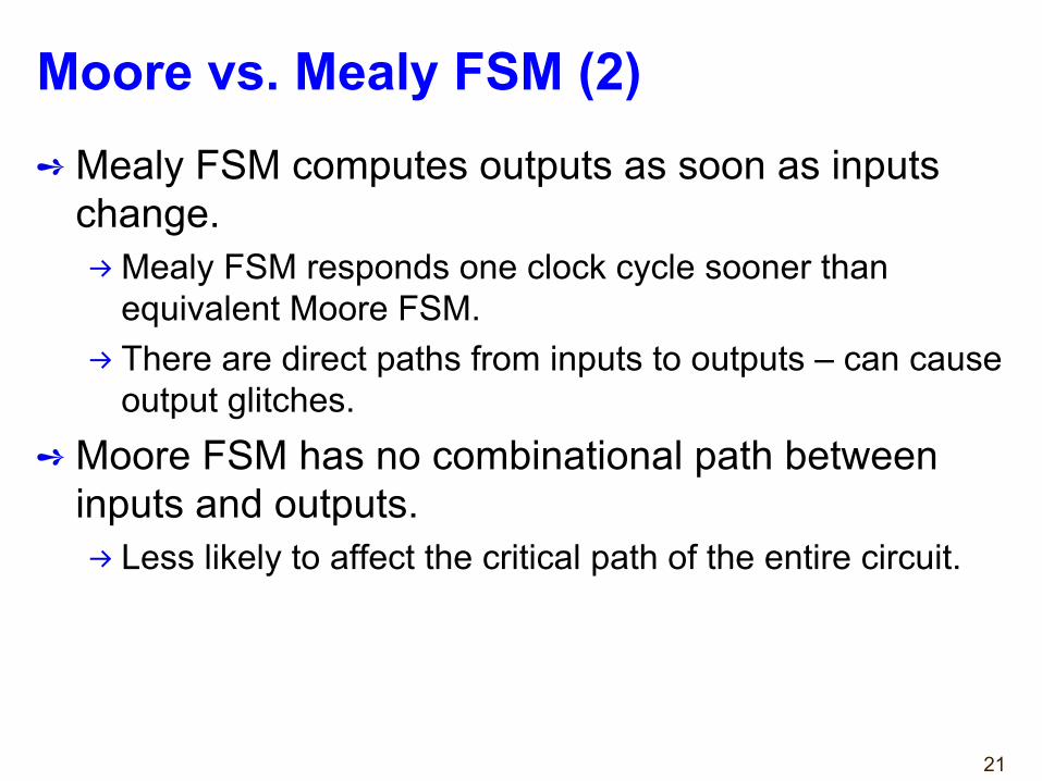
Moore vs. Mealy FSM (2)➺ Mealy FSM computes outputs as soon as inputs
change.→Mealy FSM responds one clock cycle sooner than
equivalent Moore FSM.→ There are direct paths from inputs to outputs – can cause
output glitches.➺ Moore FSM has no combinational path between
inputs and outputs.→ Less likely to affect the critical path of the entire circuit.
22
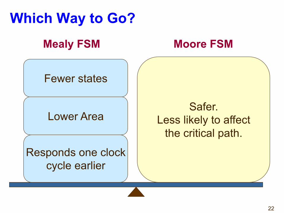
Which Way to Go?
Safer.Less likely to affect
the critical path.
Mealy FSM Moore FSM
Lower Area
Responds one clockcycle earlier
Fewer states
23
Finite State Machinesin VHDL
24
FSMs in VHDL➺ Finite State Machines can be easily described with
processes.➺ Synthesis tools understand FSM description if
certain rules are followed.→ State transitions should be described in a process
sensitive to clock and asynchronous reset signals only.→ Output function described using rules for combinational
logic, i.e. as concurrent statements or a process with all inputs and state variables in the sensitivity list.
25
Moore FSM
StateRegister
Next Statefunction
Outputfunction
Inputs
Present State
Next State
Outputs
process(clock, reset)
concurrent statements
clockreset
26
Mealy FSM
Next Statefunction
Outputfunction
Inputs
Present StateNext State
Outputs
StateRegister
process(clock, reset)
concurrent statements
clockreset
27
Moore FSM - Example 1
➺ Moore FSM that Recognizes Sequence “10”
S0 / 0 S1 / 0 S2 / 1
0
0
0
1
11
reset
28
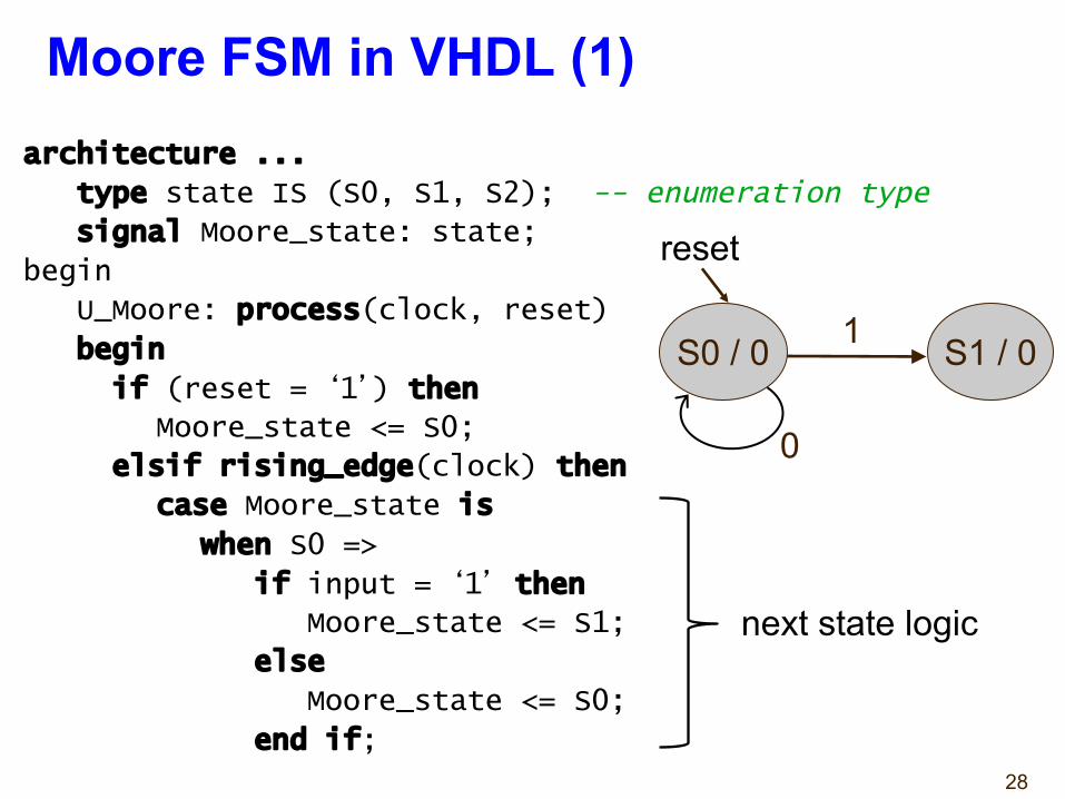
Moore FSM in VHDL (1)architecture ...
type state IS (S0, S1, S2); -- enumeration type
signal Moore_state: state;
begin
U_Moore: process(clock, reset)
begin
if (reset = ‘1’) then
Moore_state <= S0;
elsif rising_edge(clock) then
case Moore_state is
when S0 =>
if input = ‘1’ then
Moore_state <= S1;
else
Moore_state <= S0;
end if;
S0 / 0 S1 / 0
0
1
next state logic
reset
29
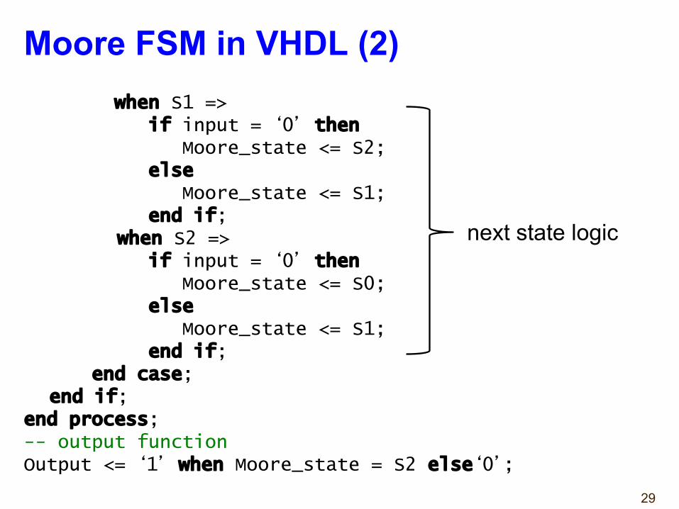
Moore FSM in VHDL (2)when S1 =>
if input = ‘0’ thenMoore_state <= S2;
elseMoore_state <= S1;
end if;when S2 =>
if input = ‘0’ thenMoore_state <= S0;
else Moore_state <= S1;
end if;end case;
end if;end process;-- output functionOutput <= ‘1’ when Moore_state = S2 else‘0’;
next state logic
30
Mealy FSM - Example 1
➺ Mealy FSM that Recognizes Sequence “10”.
S0 S1
0 / 01 / 0 1 / 0
0 / 1reset
31
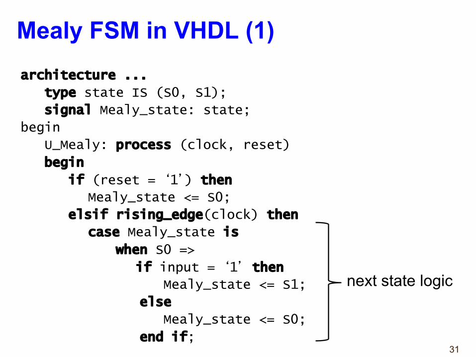
Mealy FSM in VHDL (1)architecture ...
type state IS (S0, S1);
signal Mealy_state: state;
begin
U_Mealy: process (clock, reset)
begin
if (reset = ‘1’) then
Mealy_state <= S0;
elsif rising_edge(clock) then
case Mealy_state is
when S0 =>
if input = ‘1’ then
Mealy_state <= S1;
else
Mealy_state <= S0;
end if;
next state logic
32
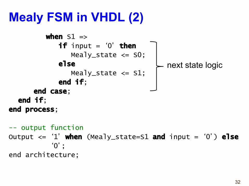
Mealy FSM in VHDL (2)when S1 =>
if input = ‘0’ then
Mealy_state <= S0;
else
Mealy_state <= S1;
end if;
end case;
end if;
end process;
-- output function
Output <= ‘1’ when (Mealy_state=S1 and input = ‘0’) else
‘0’;
end architecture;
next state logic
33
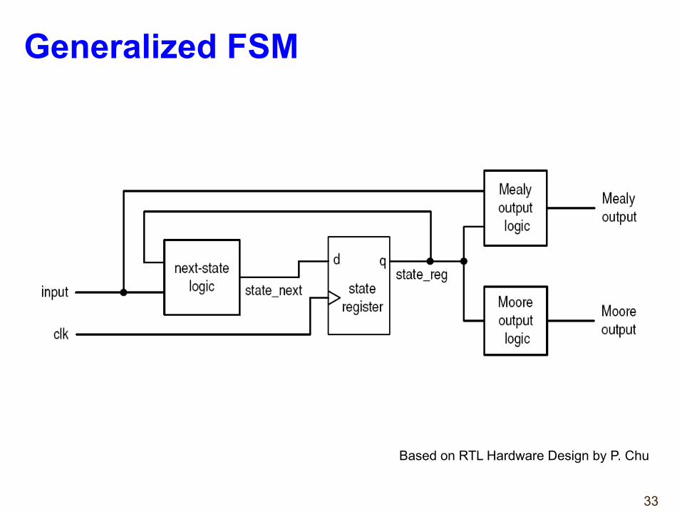
Generalized FSM
Based on RTL Hardware Design by P. Chu
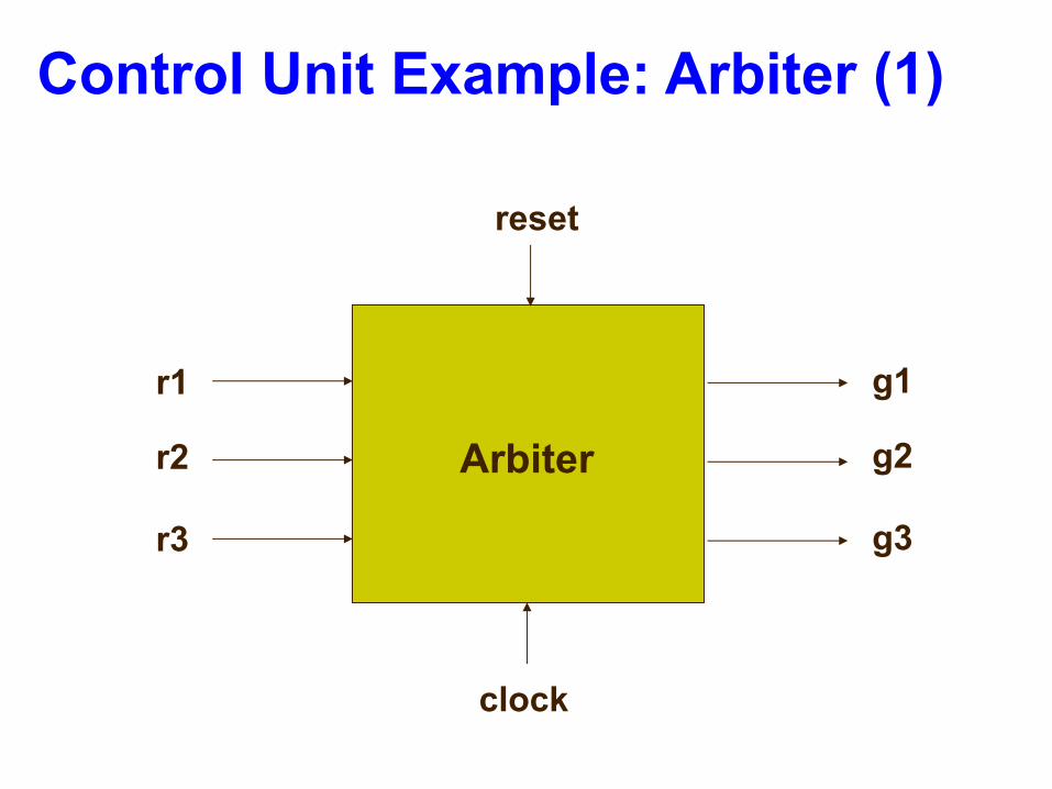
Control Unit Example: Arbiter (1)
Arbiter
reset
r1
r2
r3
g1
g2
g3
clock
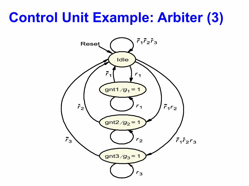
r 1 r 2
r 1 r 2 r 3
Idle
Reset
gnt1 g 1 ⁄ 1 =
gnt2 g 2 ⁄ 1 =
gnt3 g 3 ⁄ 1 =
r 1 r 1
r 1
r 2
r 3
r 2
r 3
r 1 r 2 r 3
r 1 r 2
r 1 r 2 r 3
Idle
Reset
gnt1 g 1 ⁄ 1 =
gnt2 g 2 ⁄ 1 =
gnt3 g 3 ⁄ 1 =
r 1 r 1
r 1
r 2
r 3
r 2
r 3
r 1 r 2 r 3
Control Unit Example: Arbiter (3)
36
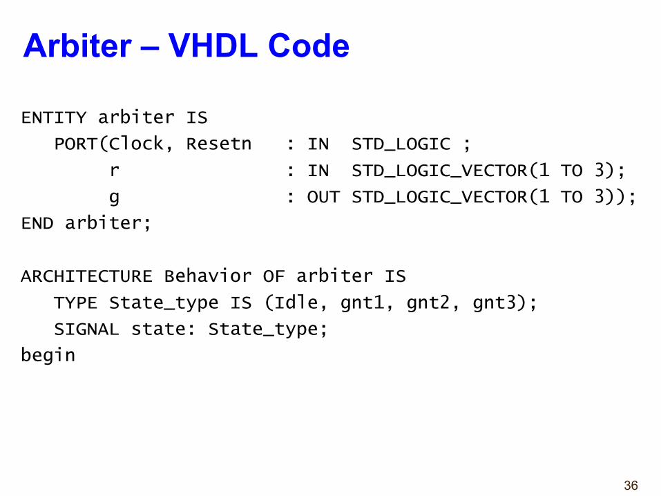
ENTITY arbiter IS
PORT(Clock, Resetn : IN STD_LOGIC ;
r : IN STD_LOGIC_VECTOR(1 TO 3);
g : OUT STD_LOGIC_VECTOR(1 TO 3));
END arbiter;
ARCHITECTURE Behavior OF arbiter IS
TYPE State_type IS (Idle, gnt1, gnt2, gnt3);
SIGNAL state: State_type;
begin
Arbiter – VHDL Code
37
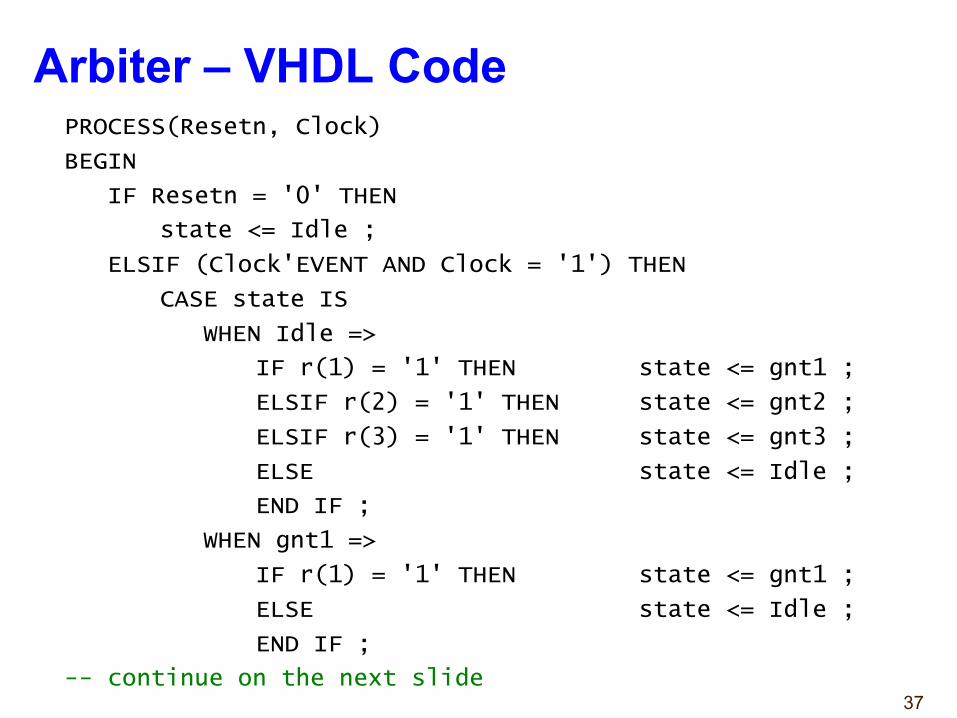
PROCESS(Resetn, Clock)
BEGIN
IF Resetn = '0' THEN
state <= Idle ;
ELSIF (Clock'EVENT AND Clock = '1') THEN
CASE state IS
WHEN Idle =>
IF r(1) = '1' THEN state <= gnt1 ;
ELSIF r(2) = '1' THEN state <= gnt2 ;
ELSIF r(3) = '1' THEN state <= gnt3 ;
ELSE state <= Idle ;
END IF ;
WHEN gnt1 =>
IF r(1) = '1' THEN state <= gnt1 ;
ELSE state <= Idle ;
END IF ;
-- continue on the next slide
Arbiter – VHDL Code
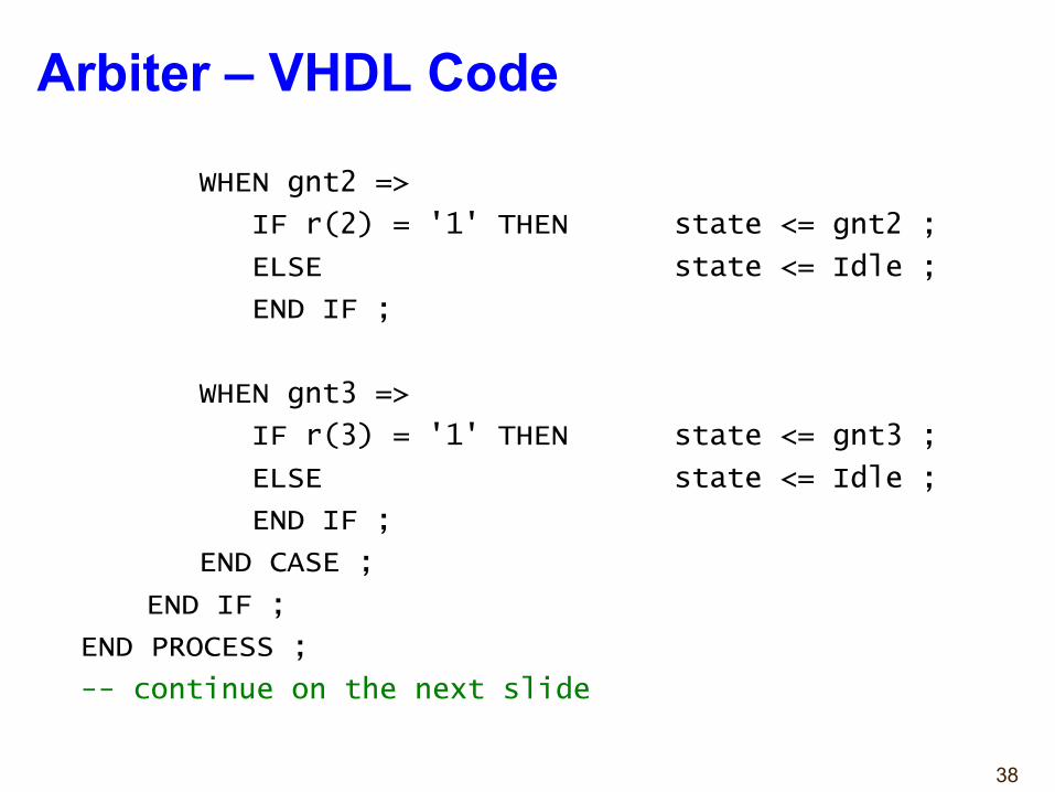
38
WHEN gnt2 =>
IF r(2) = '1' THEN state <= gnt2 ;
ELSE state <= Idle ;
END IF ;
WHEN gnt3 =>
IF r(3) = '1' THEN state <= gnt3 ;
ELSE state <= Idle ;
END IF ;
END CASE ;
END IF ;
END PROCESS ;
-- continue on the next slide
Arbiter – VHDL Code
39
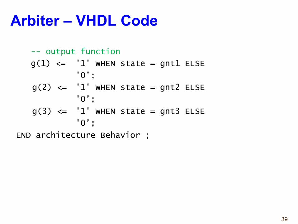
-- output function
g(1) <= '1' WHEN state = gnt1 ELSE
'0’;
g(2) <= '1' WHEN state = gnt2 ELSE
'0’;
g(3) <= '1' WHEN state = gnt3 ELSE
'0’;
END architecture Behavior ;
Arbiter – VHDL Code
Case Study 1Debouncing Circuit
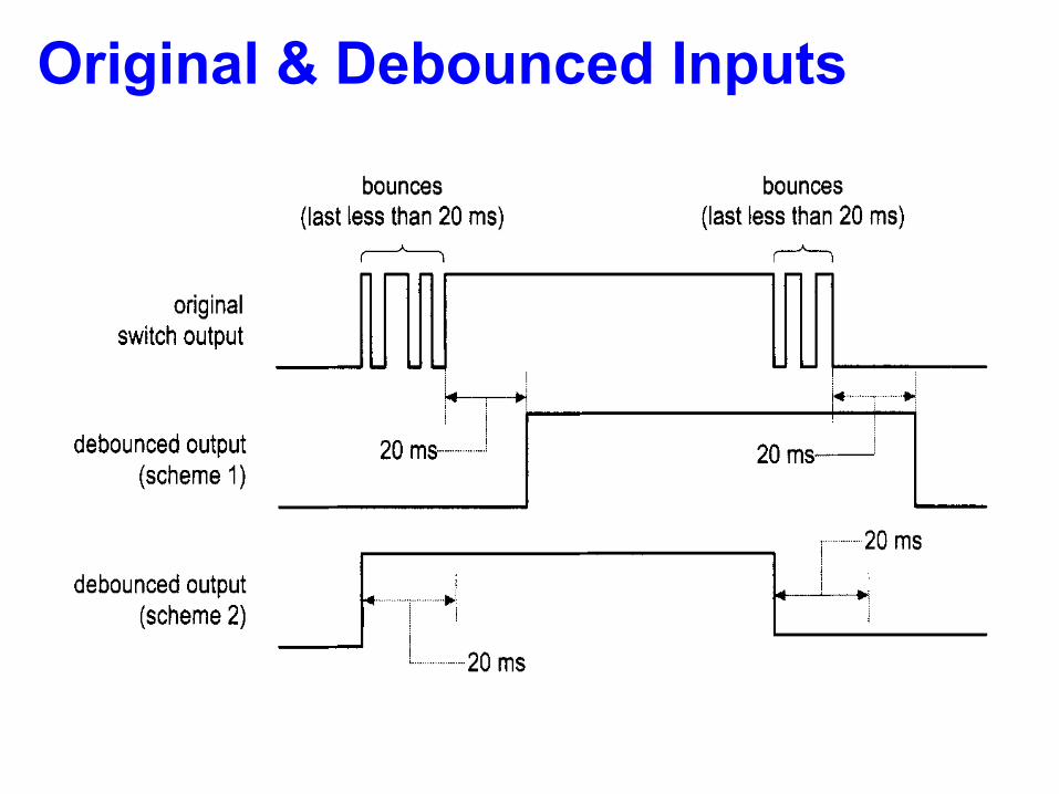
Original & Debounced InputsDESIGN EXAMPLES 11 9
original switch output
bounces bounces (last less than 20 ms) (last less than 20 ms)
- -
- - -
L 20 ms- debounced output (scheme 1) *Oms I
I , 20ms debounced output
(scheme 2)
20 ms - ;
Figure 5.8 Original and debounced waveforms.
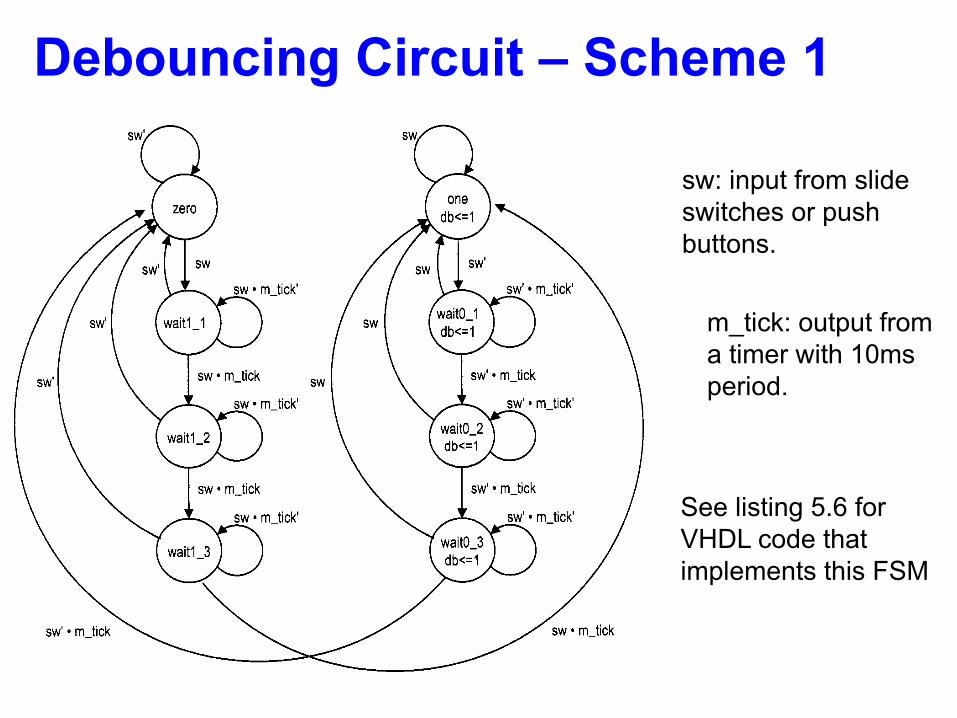
Figure 5.9 State diagram of a debouncing circuit.
Debouncing Circuit – Scheme 1
DESIGN EXAMPLES 11 9
original switch output
bounces bounces (last less than 20 ms) (last less than 20 ms)
- -
- - -
L 20 ms- debounced output (scheme 1) *Oms I
I , 20ms debounced output
(scheme 2)
20 ms - ;
Figure 5.8 Original and debounced waveforms.
Figure 5.9 State diagram of a debouncing circuit.
sw: input from slide switches or push buttons.
m_tick: output from a timer with 10ms period.
See listing 5.6 for VHDL code that implements this FSM
Debouncing Testing Circuit122 FSM
- - btn(1) level tick - en q - > detector
edge counter > 4- hex0 sseg sseg - hex1 an - an
95
sw db - level tick -
> debouncing edge clk - > detector
105
en 9 disp-mux-hex counter
> reset
I10
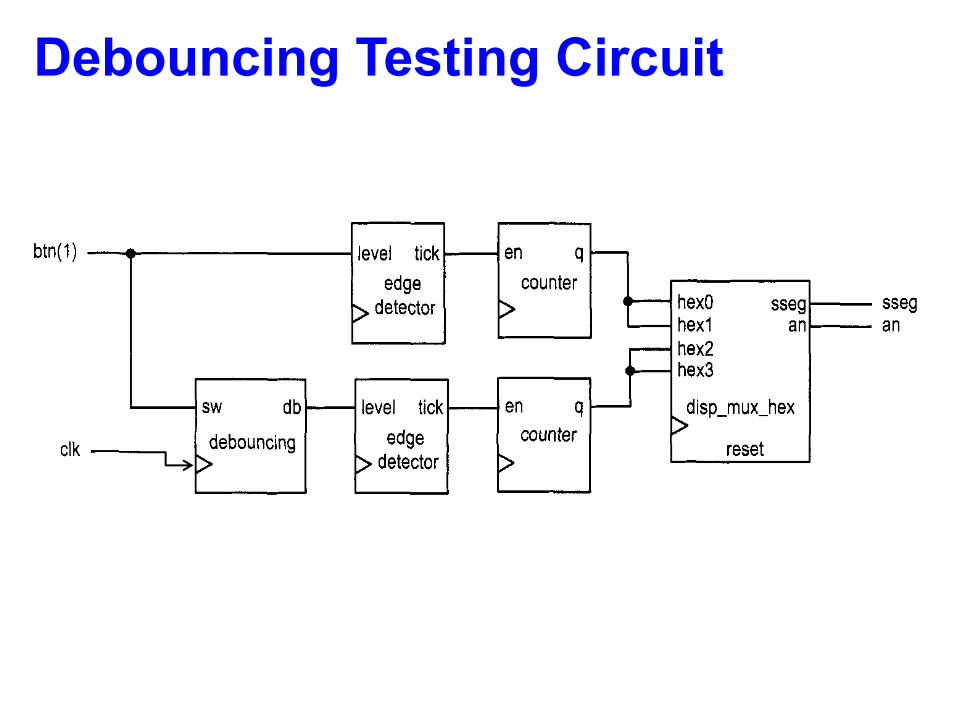
Figure 5.10 Debouncing testing circuit.
end i f ; when w a i t 0 - 2 = >
db < = ’ I > ; i f s w = ’ 1 ’ then
e l s e s t a t e - n e x t <= o n e ;
i f m - t i c k = ’ l J then
end i f ; s t a t e - n e x t <= w a i t 0 - 3 ;
end i f ; when w a i t 0 - 3 = >
db < = ’ I > ; i f s w = ’ 1 ’ then
e l s e s t a t e - n e x t <= o n e ;
i f m - t i c k = ’ l ’ then
end i f ; s t a t e - n e x t <= z e r o ;
end i f ; end c a s e ;
end p r o c e s s ; 11s end a r c h ;
5.3.3 Testing circuit
We use a bounce counting circuit to verify operation of the rising-edge detector and the debouncing circuit. The block diagram is shown in Figure 5.10. The input of the verification circuit is from a pushbutton switch. In the lower part, the signal is first fed to the debouncing circuit and then to the rising-edge detector. Therefore, a one-clock-cycle tick is generated each time the button is pressed and released. The tick in turn controls the enable input of an 8-bit counter, whose content is passed to the LED time-multiplexing circuit and shown on the left two digits of the prototyping board’s seven-segment LED display. In the upper part, the input signal is fed directly to the edge detector without the debouncing circuit, and the number is shown on the right two digits of the prototyping board’s seven-segment LED display. The bottom counter thus counts one desired 0-to- 1 transition as well as the bounces.
44
Case Study 2Fibonacci Number
(section 6.3.1, Chu’s book)
45
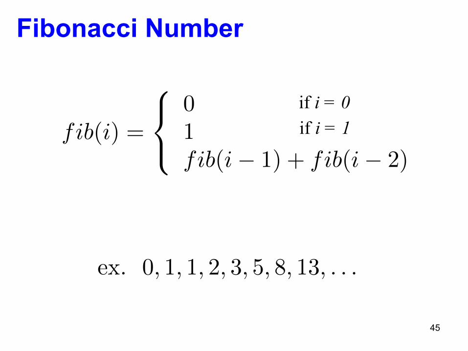
Fibonacci Number
fib(i) =
8<
:
01fib(i� 1) + fib(i� 2)
if i = 0if i = 1
ex. 0, 1, 1, 2, 3, 5, 8, 13, . . .
46
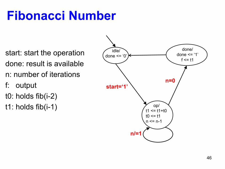
Fibonacci Number
idle/done <= ‘0’
done/done <= ‘1’
f <= t1
op/t1 <= t1+t0t0 <= t1n <= n-1
n=0
n/=1
start: start the operationdone: result is availablen: number of iterationsf: outputt0: holds fib(i-2)t1: holds fib(i-1)
start=‘1’

47
Division
48
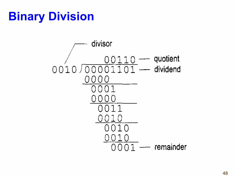
Binary Division144 FSMD
rh
divisor
0 0 11 0 - quotient 0 0 1 0 1 0 0 0 0 1 10 1 - dividend
0000 0001 0000 0011
rI
Figure 6.10 Long division of two 4-bit unsigned integers.
Figure 6.11 Sketch of division circuit’s data path.
be summarized as follows: 1. Double the dividend width by appending 0’s in front and align the divisor to the
leftmost bit of the extended dividend. 2. If the corresponding dividend bits are greater than or equal to the divisor, subtract the
divisor from the dividend bits and make the corresponding quotient bit 1. Otherwise, keep the original dividend bits and make the quotient bit 0.
3. Append one additional dividend bit to the previous result and shift the divisor to the right one position.
4. Repeat steps 2 and 3 until all dividend bits are used. The sketch of the data path is shown in Figure 6.11. Initially, the divisor is stored in the
d register and the extended dividend is stored in the rh and rl registers. In each iteration, the rh and rl registers are shifted to the left one position. This corresponds to shifting the divisor to the right of the previous algorithm. We can then compare rh and d and perform subtraction if r h is greater than or equal to d. When r h and rl are shifted to the left, the rightmost bit of rl becomes available. It can be used to store the current quotient bit. After
49
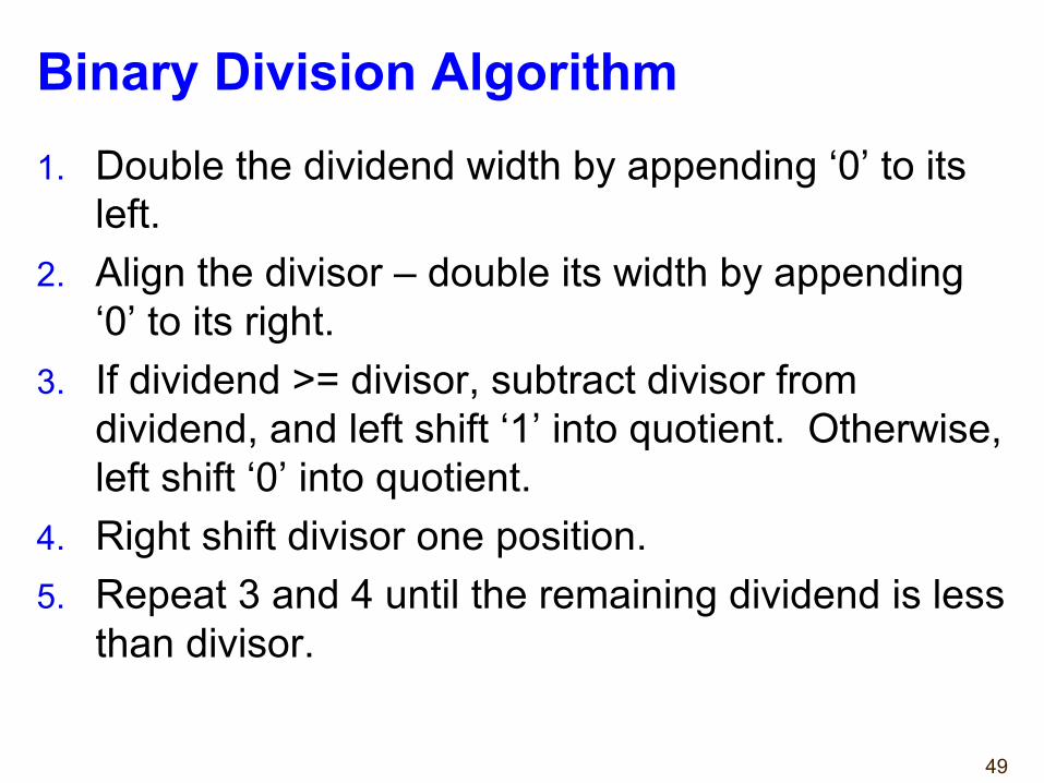
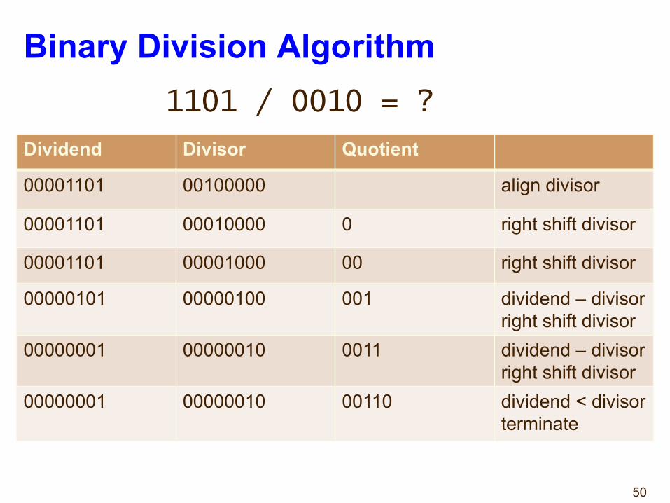
Binary Division Algorithm1. Double the dividend width by appending ‘0’ to its
left.2. Align the divisor – double its width by appending
‘0’ to its right.3. If dividend >= divisor, subtract divisor from
dividend, and left shift ‘1’ into quotient. Otherwise, left shift ‘0’ into quotient.
4. Right shift divisor one position.5. Repeat 3 and 4 until the remaining dividend is less
than divisor.
50
Binary Division Algorithm1101 / 0010 = ?
Dividend Divisor Quotient
00001101 00100000 align divisor
00001101 00010000 0 right shift divisor
00001101 00001000 00 right shift divisor
00000101 00000100 001 dividend – divisorright shift divisor
00000001 00000010 0011 dividend – divisorright shift divisor
00000001 00000010 00110 dividend < divisorterminate
51
Binary Division Algorithm – FSM
52
VHDL Variables
Chapter 3: VHDL Support
Signal Assignment in a Process VHDL Coding Example---- Signal assignment in a process---- Download: http://www.xilinx.com/txpatches/pub/documentation/misc/xstug_examples.zip-- File: VHDL_Language_Support/signals_variables/signal_in_process.vhd--entity signal_in_process is
port (A, B : in BIT;S : out BIT );
end signal_in_process;
architecture archi of signal_in_process isbegin
process (A, B)begin
S <= ’0’ ;if ((A and B) = ’1’) then
S <= ’1’ ;end if;
end process;end archi;
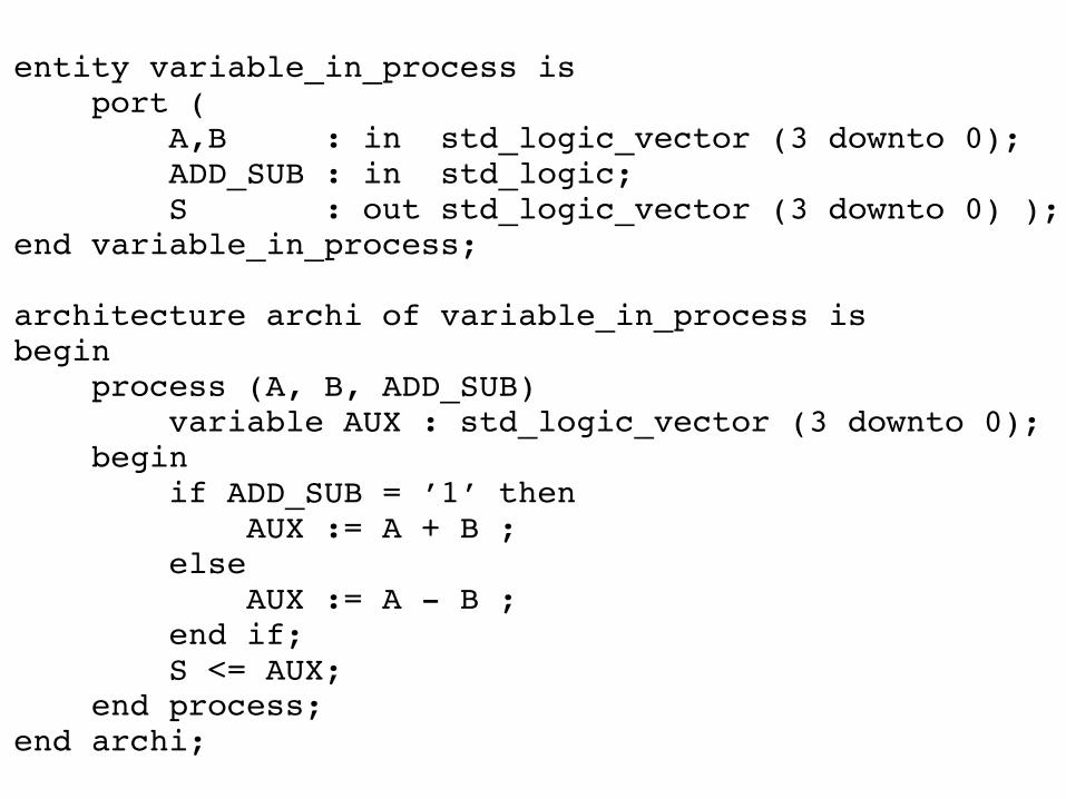
Variable and Signal Assignment in a Process VHDL Coding Example---- Variable and signal assignment in a process---- Download: http://www.xilinx.com/txpatches/pub/documentation/misc/xstug_examples.zip-- File: VHDL_Language_Support/signals_variables/variable_in_process.vhd--library ieee;use ieee.std_logic_1164.all;use ieee.std_logic_arith.all;use ieee.std_logic_unsigned.all;
entity variable_in_process isport (
A,B : in std_logic_vector (3 downto 0);ADD_SUB : in std_logic;S : out std_logic_vector (3 downto 0) );
end variable_in_process;
architecture archi of variable_in_process isbegin
process (A, B, ADD_SUB)variable AUX : std_logic_vector (3 downto 0);
beginif ADD_SUB = ’1’ then
AUX := A + B ;else
AUX := A - B ;end if;S <= AUX;
end process;end archi;
VHDL If-Else Statementsif-else and if-elsif-else statements use true-false conditions to execute statements.
• If the expression evaluates to true, the if branch is executed.
• If the expression evaluates to false, x, or z, the else branch is executed.
• A block of multiple statements is executed in an if or else branch.
• begin and end keywords are required.
• if-else statements can be nested.
XST User Guide for Virtex-6, Spartan-6, and 7 Series DevicesUG687 (v 14.5) March 20, 2013 www.xilinx.com 47
Send Feedback
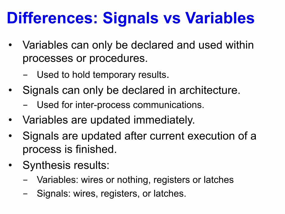
Differences: Signals vs Variables• Variables can only be declared and used within
processes or procedures.- Used to hold temporary results.
• Signals can only be declared in architecture.- Used for inter-process communications.
• Variables are updated immediately.• Signals are updated after current execution of a
process is finished.• Synthesis results:- Variables: wires or nothing, registers or latches- Signals: wires, registers, or latches.
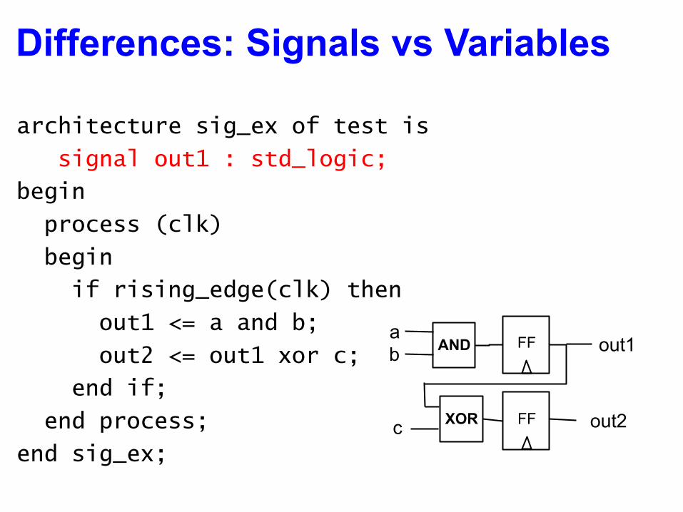
Differences: Signals vs Variables
architecture sig_ex of test is
signal out1 : std_logic;
begin
process (clk)
begin
if rising_edge(clk) then
out1 <= a and b;
out2 <= out1 xor c;
end if;
end process;
end sig_ex;
FF
FF
AND
XOR
ab
c
out1
out2
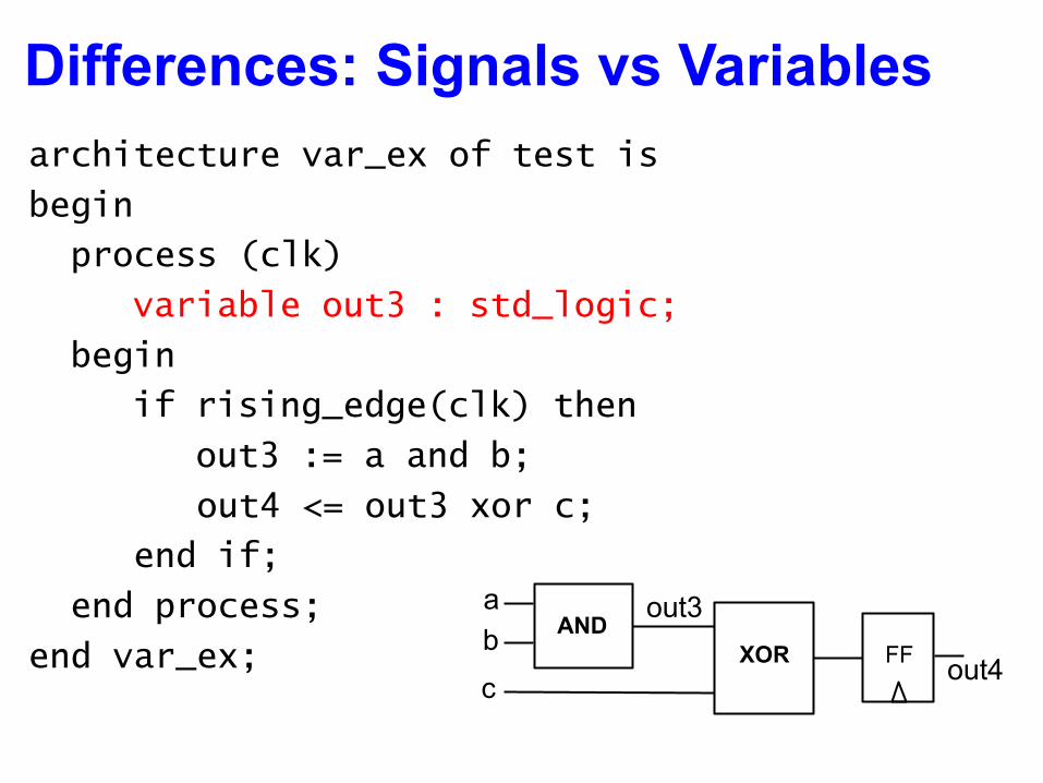
Differences: Signals vs Variablesarchitecture var_ex of test is
begin
process (clk)
variable out3 : std_logic;
begin
if rising_edge(clk) then
out3 := a and b;
out4 <= out3 xor c;
end if;
end process;
end var_ex;AND
XOR
abc
FF
out3
out4
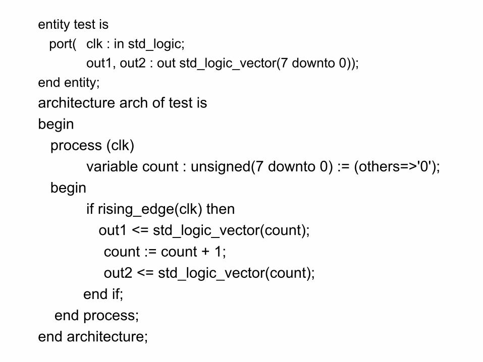
entity test isport( clk : in std_logic;
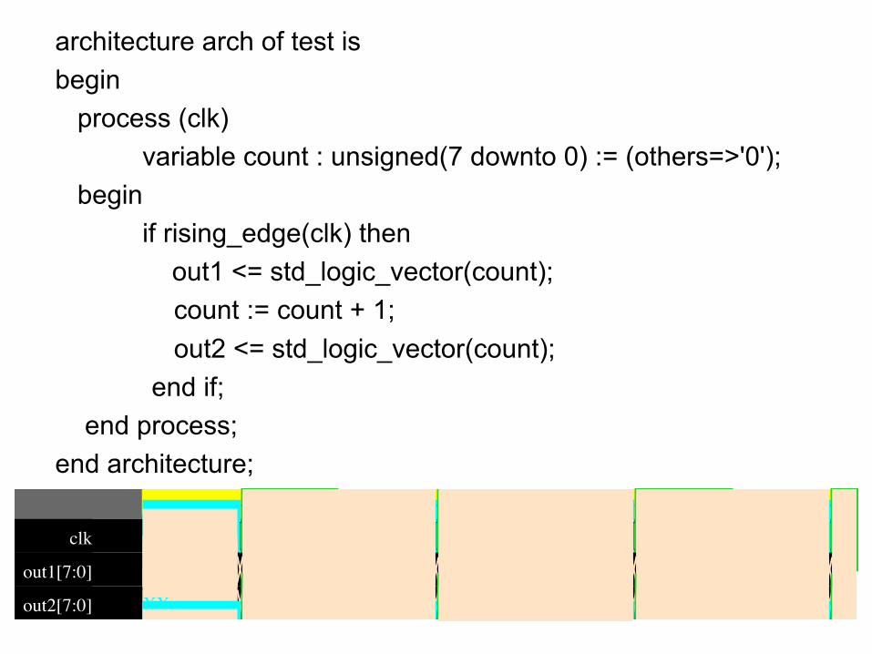
out1, out2 : out std_logic_vector(7 downto 0));end entity;architecture arch of test isbegin
process (clk)variable count : unsigned(7 downto 0) := (others=>'0');
beginif rising_edge(clk) then
out1 <= std_logic_vector(count);count := count + 1; out2 <= std_logic_vector(count);
end if;end process;
end architecture;
architecture arch of test isbegin
process (clk)variable count : unsigned(7 downto 0) := (others=>'0');
beginif rising_edge(clk) then
out1 <= std_logic_vector(count);count := count + 1; out2 <= std_logic_vector(count);
end if;end process;
end architecture;
6/6/18, 9(30 AMEPWave Waveform Viewer
Page 1 of 1https://www.edaplayground.com/embed/launchEpwave?id=c773f5e1-6a20-45ac-aa6e-523e8a…nk=https%3A%2F%2Fwww.edaplayground.com%2F&from=https%3A%2F%2Fwww.edaplayground.com
0 2,000 4,000 6,000 8,000 10,000 12,000 14,000 16,000 18,000 20,000
clk
out1[7:0] XX 0 1 2 3 4 5 6 7 8 9 a
out2[7:0] XX 1 2 3 4 5 6 7 8 9 a b
clk
out1[7:0] XX 0 1 2 3 4 5 6 7 8 9 a
out2[7:0] XX 1 2 3 4 5 6 7 8 9 a b
Note: To revert to EPWave opening in a new browser window, set that option on your user page.
From: 0ps To: 22,000ps
Get Signals Radix ! " # 100% $ %
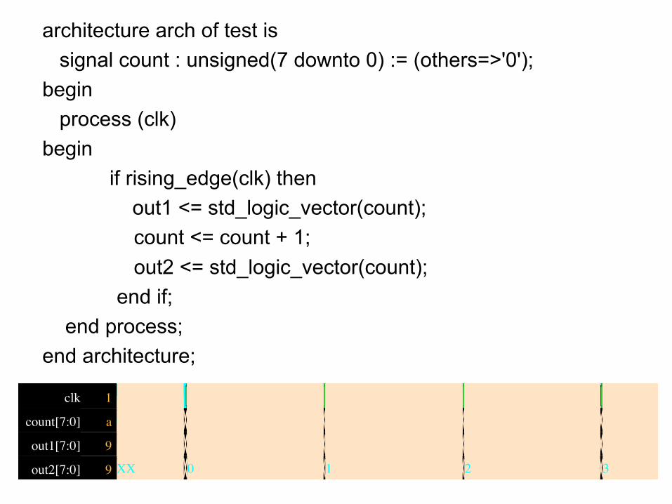
architecture arch of test issignal count : unsigned(7 downto 0) := (others=>'0');
beginprocess (clk)
beginif rising_edge(clk) then
out1 <= std_logic_vector(count);count <= count + 1; out2 <= std_logic_vector(count);
end if;end process;
end architecture;
6/6/18, 9(51 AMEPWave Waveform Viewer
Page 1 of 1https://www.edaplayground.com/embed/launchEpwave?id=81075fd7-f2a9-4818-8cba-2e3ab21…nk=https%3A%2F%2Fwww.edaplayground.com%2F&from=https%3A%2F%2Fwww.edaplayground.com
0 2,000 4,000 6,000 8,000 10,000 12,000 14,000 16,000 18,000 20,000
clk 1
out1[7:0] 9 XX 0 1 2 3 4 5 6 7 8 9 a
out2[7:0] 9 XX 0 1 2 3 4 5 6 7 8 9 a
clk 1
count[7:0] a 0 1 2 3 4 5 6 7 8 9 a b
out1[7:0] 9 XX 0 1 2 3 4 5 6 7 8 9 a
out2[7:0] 9 XX 0 1 2 3 4 5 6 7 8 9 a
Note: To revert to EPWave opening in a new browser window, set that option on your user page.
From: 0ps To: 22,000ps
Get Signals Radix ! " # 100% $ % & 19,000ps
Loop Statements
61
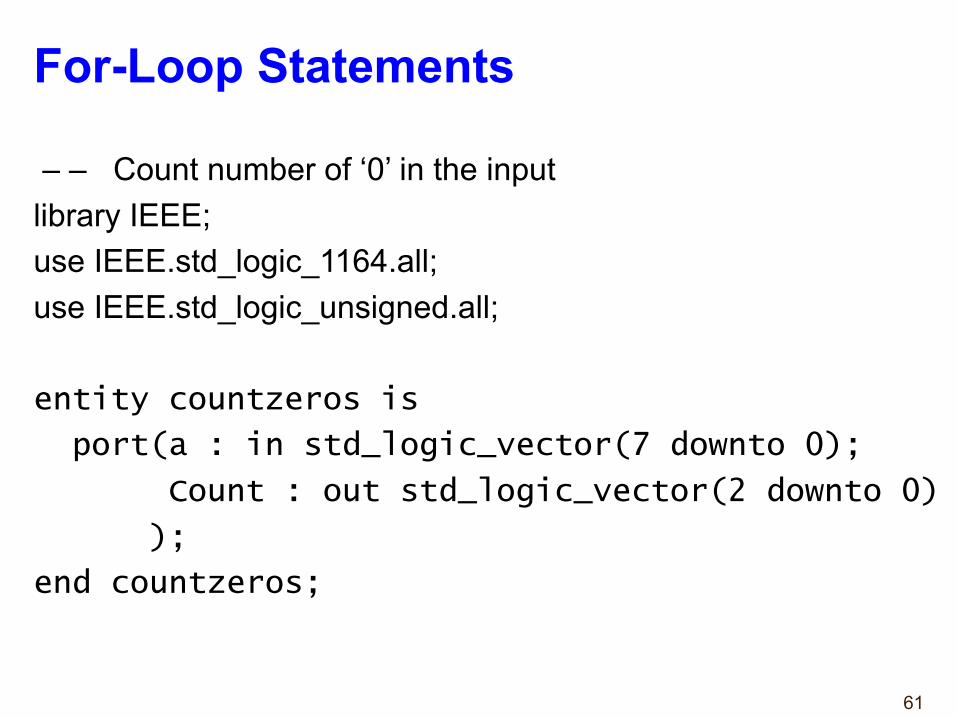
For-Loop Statements
– – Count number of ‘0’ in the inputlibrary IEEE; use IEEE.std_logic_1164.all; use IEEE.std_logic_unsigned.all;
entity countzeros is
port(a : in std_logic_vector(7 downto 0);
Count : out std_logic_vector(2 downto 0)
);
end countzeros;
62
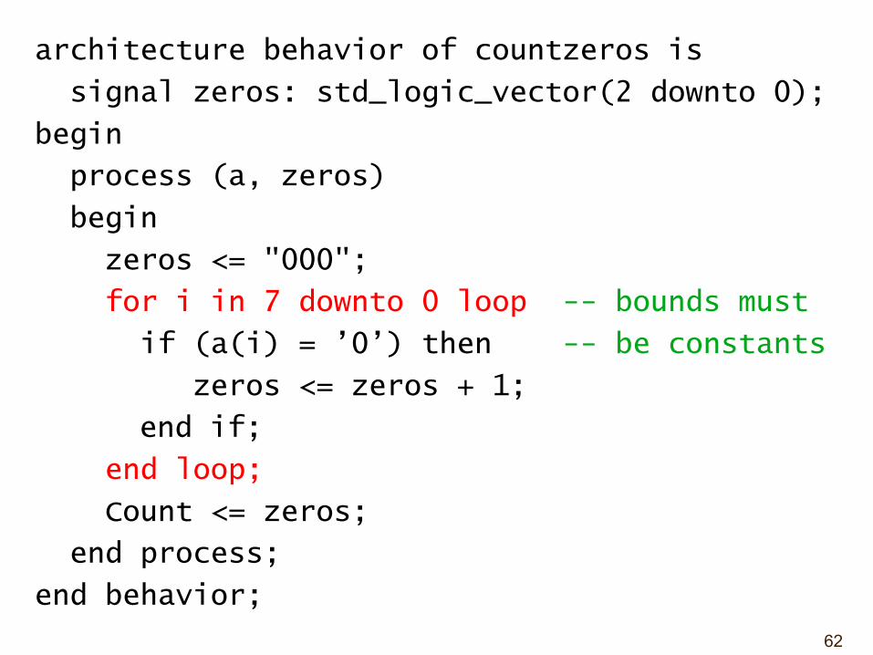
architecture behavior of countzeros is
signal zeros: std_logic_vector(2 downto 0);
begin
process (a, zeros)
begin
zeros <= "000";
for i in 7 downto 0 loop -- bounds must
if (a(i) = ’0’) then -- be constants
zeros <= zeros + 1;
end if;
end loop;
Count <= zeros;
end process;
end behavior;
63
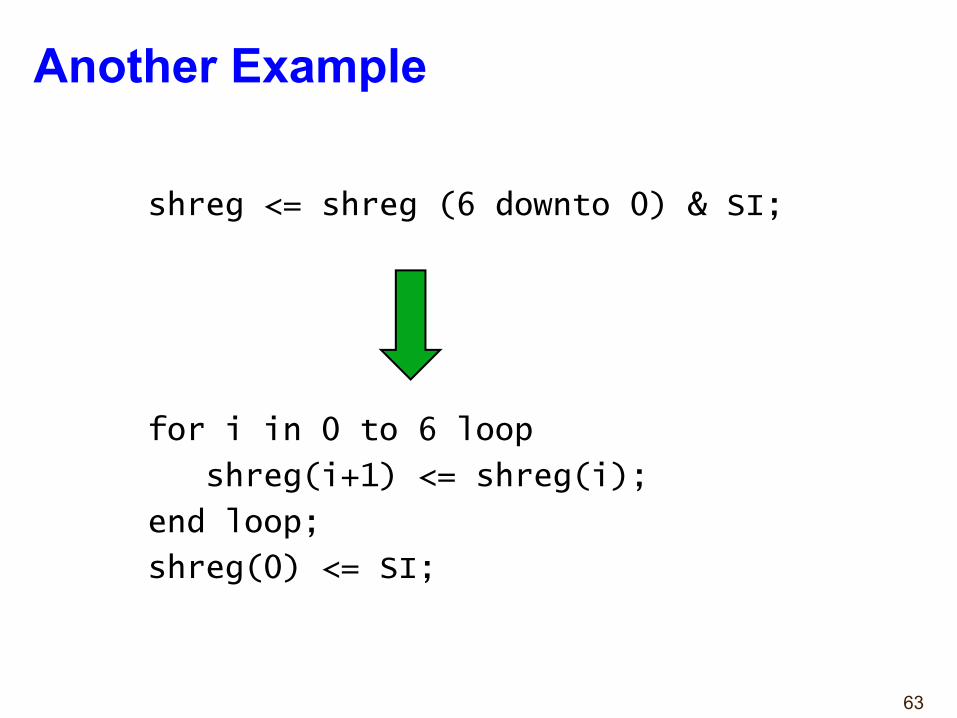
Another Example
shreg <= shreg (6 downto 0) & SI;
for i in 0 to 6 loop
shreg(i+1) <= shreg(i);
end loop;
shreg(0) <= SI;
64
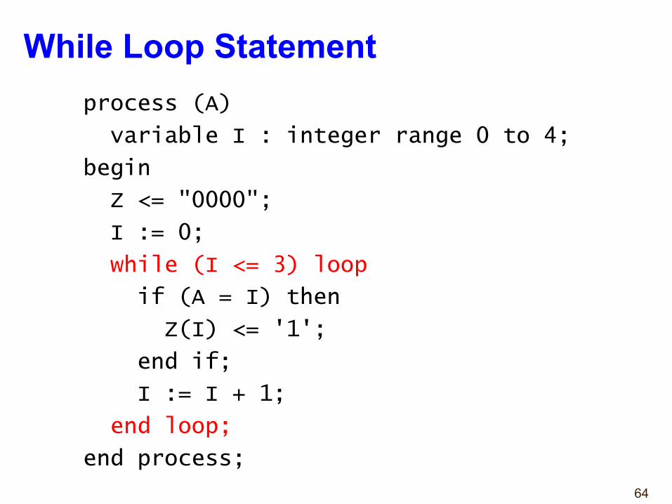
While Loop Statementprocess (A)
variable I : integer range 0 to 4;
begin
Z <= "0000";
I := 0;
while (I <= 3) loop
if (A = I) then
Z(I) <= '1';
end if;
I := I + 1;
end loop;
end process;
Alternative Coding Stylesby Dr. Chu
(to be used with caution)
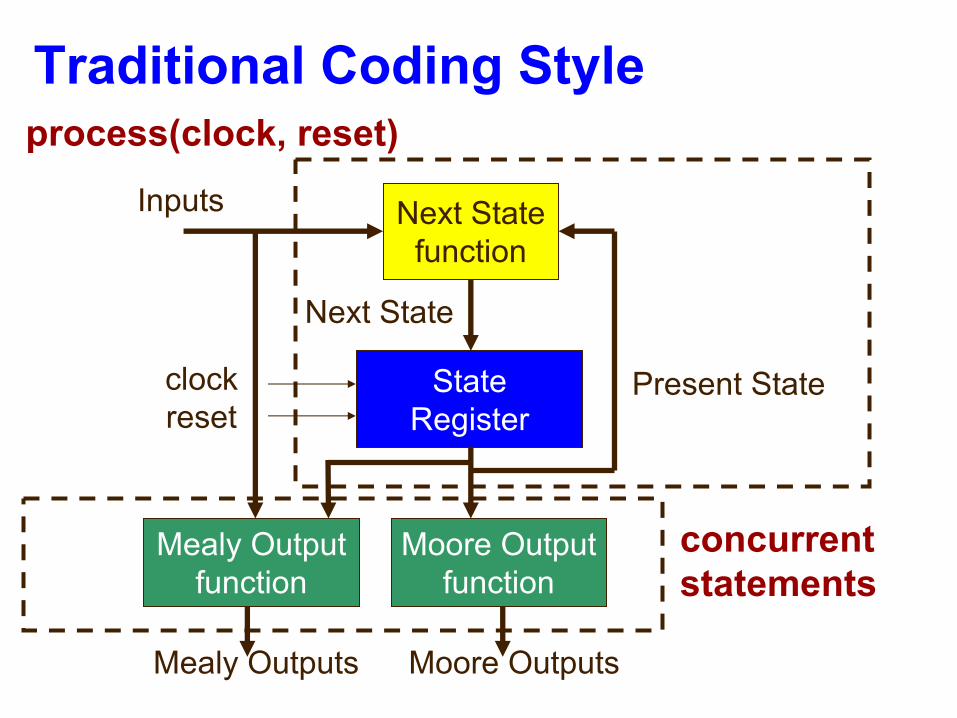
Traditional Coding Style
StateRegister
Next Statefunction
Moore Outputfunction
Inputs
Present State
Next State
clockreset
process(clock, reset)
concurrent statements
Mealy Outputfunction
Mealy Outputs Moore Outputs
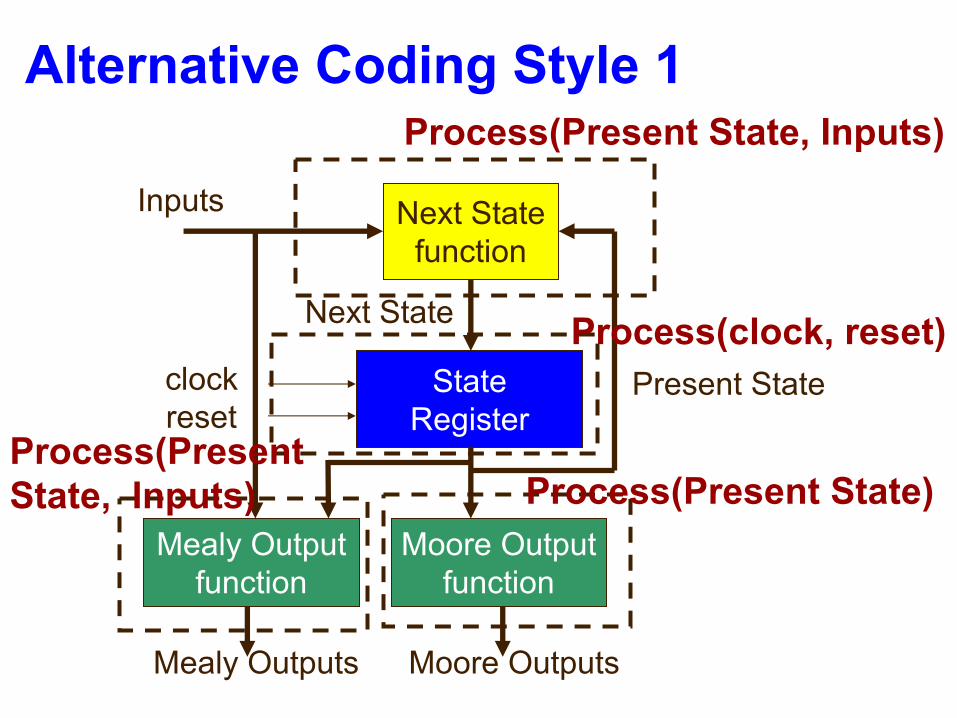
Alternative Coding Style 1
StateRegister
Next Statefunction
Moore Outputfunction
Inputs
Present State
Next State
clockreset
Process(Present State, Inputs)
Mealy Outputfunction
Mealy Outputs Moore Outputs
Process(clock, reset)
Process(Present State)Process(Present State, Inputs)
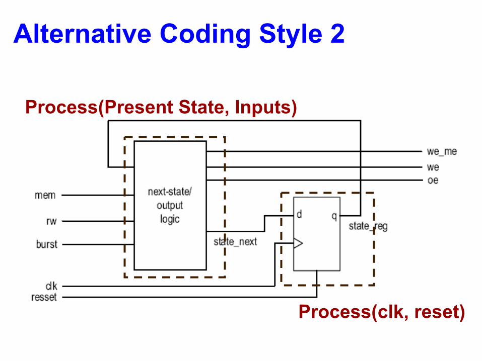
Alternative Coding Style 2
Process(clk, reset)
Process(Present State, Inputs)

Backup
70
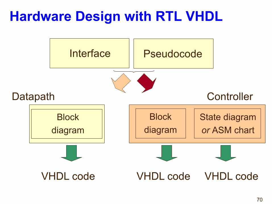
Hardware Design with RTL VHDL
Pseudocode
Datapath Controller
Blockdiagram
Blockdiagram
State diagramor ASM chart
VHDL code VHDL code VHDL code
Interface

71
Algorithmic State Machine (ASM)Charts
72
Algorithmic State Machine
Algorithmic State Machine –representation of a Finite State Machine suitable for FSMs with a larger number of inputs and outputs compared to FSMs expressed using state diagrams and state tables.
73
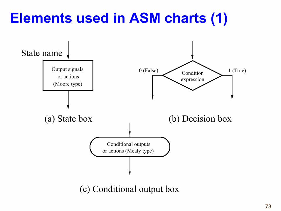
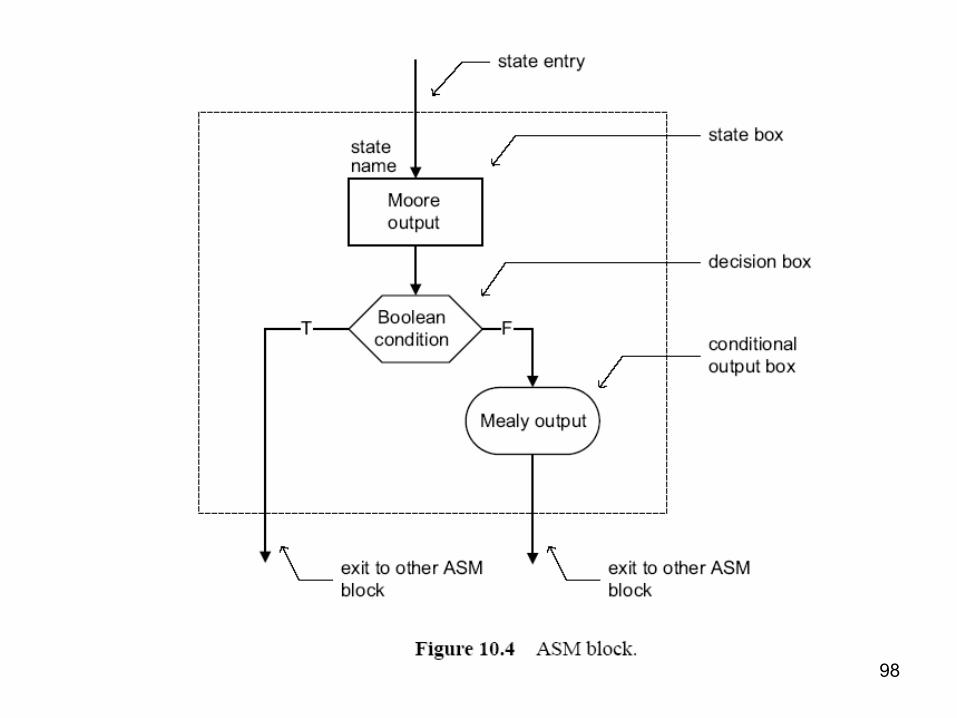
Elements used in ASM charts (1)
Output signalsor actions
(Moore type)
State name
Condition expression
0 (False) 1 (True)
Conditional outputs or actions (Mealy type)
(a) State box (b) Decision box
(c) Conditional output box
74
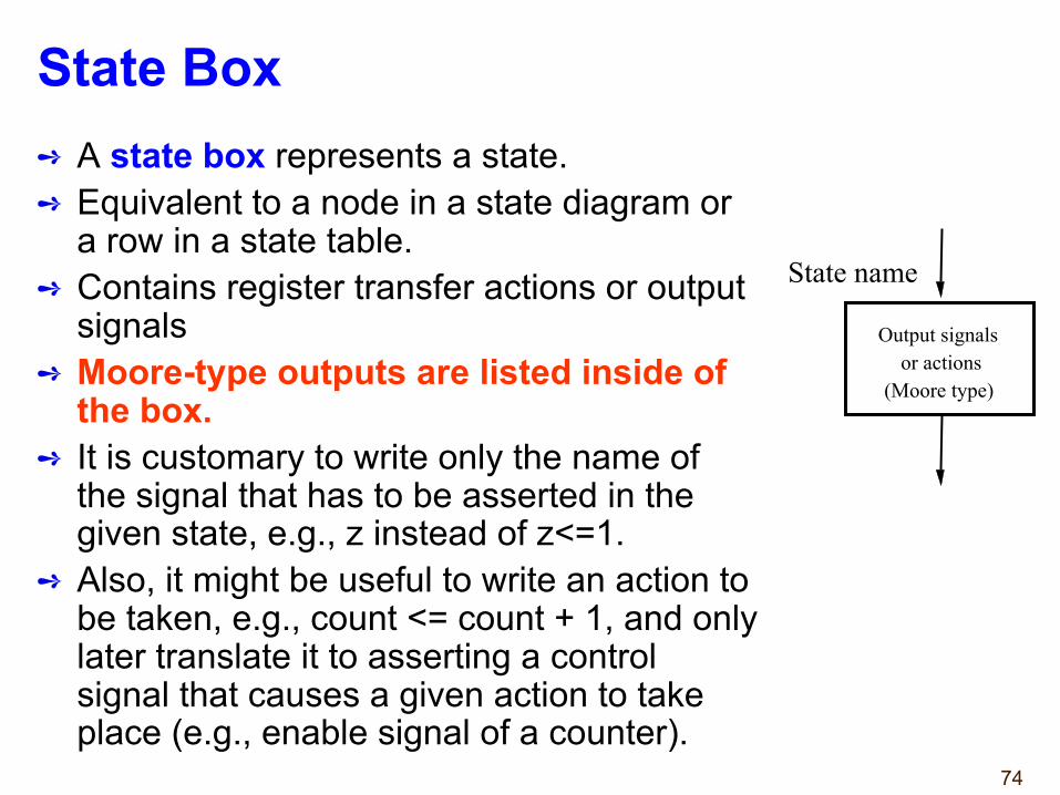
State Box➺ A state box represents a state.➺ Equivalent to a node in a state diagram or
a row in a state table.➺ Contains register transfer actions or output
signals➺ Moore-type outputs are listed inside of
the box.➺ It is customary to write only the name of
the signal that has to be asserted in the given state, e.g., z instead of z<=1.
➺ Also, it might be useful to write an action to be taken, e.g., count <= count + 1, and only later translate it to asserting a control signal that causes a given action to take place (e.g., enable signal of a counter).
Output signalsor actions
(Moore type)
State name
75
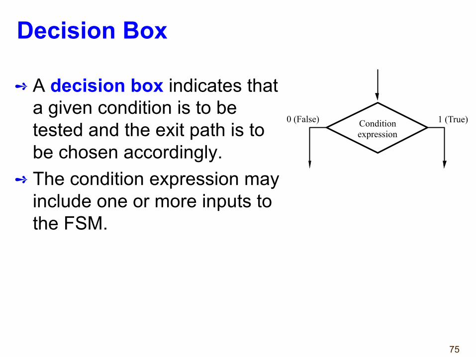
Decision Box
➺ A decision box indicates that a given condition is to be tested and the exit path is to be chosen accordingly.
➺ The condition expression may include one or more inputs to the FSM.
Condition expression
0 (False) 1 (True)
76
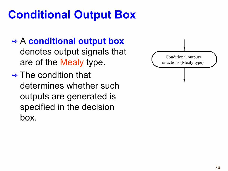
Conditional Output Box
➺ A conditional output box denotes output signals that are of the Mealy type.
➺ The condition that determines whether such outputs are generated is specified in the decision box.
Conditional outputs or actions (Mealy type)
77
ASMs Representing Simple FSMs
➺ Algorithmic state machines can model both Mealy and Moore Finite State Machines
➺ They can also model machines that are of the mixed type.
78
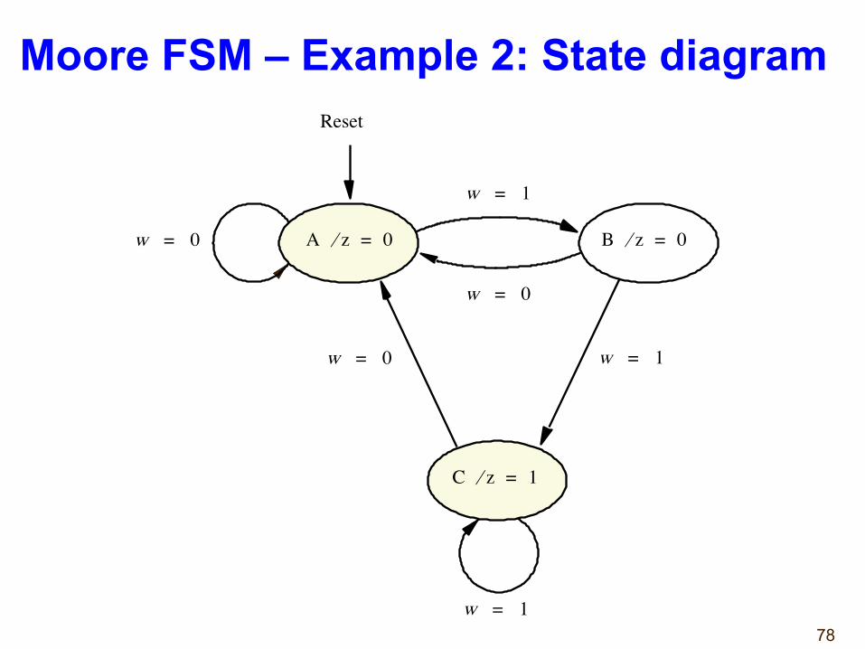
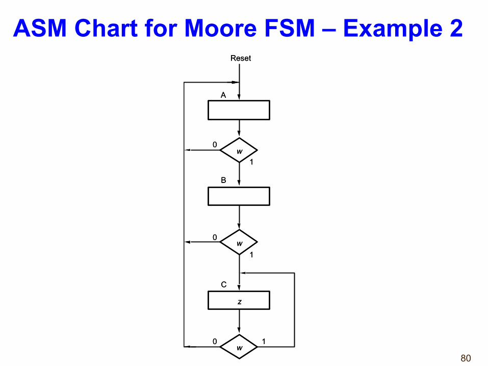
Moore FSM – Example 2: State diagram
C z 1 = ⁄
Reset
B z 0 = ⁄ A z 0 = ⁄ w 0 =
w 1 =
w 1 =
w 0 =
w 0 = w 1 =
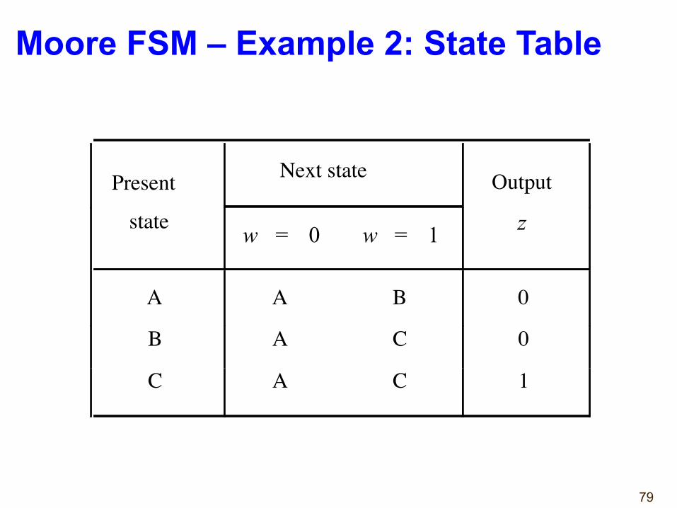
79
Present Next state Output
state w = 0 w = 1 z
A A B 0
B A C 0
C A C 1
Moore FSM – Example 2: State Table
80
w
w
w 0 1
0
1
0
1
A
B
C
z
Reset
w
w
w 0 1
0
1
0
1
A
B
C
z
Reset
ASM Chart for Moore FSM – Example 2
81
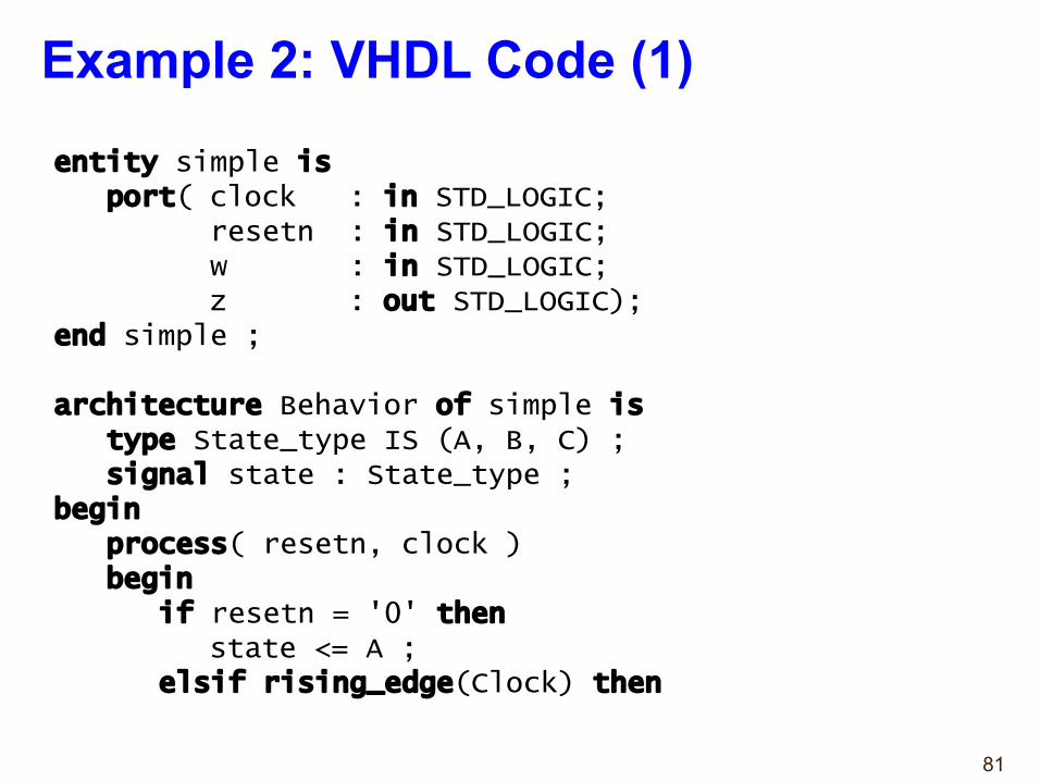
entity simple isport( clock : in STD_LOGIC;
resetn : in STD_LOGIC;w : in STD_LOGIC;z : out STD_LOGIC);
end simple ;
architecture Behavior of simple is type State_type IS (A, B, C) ;signal state : State_type ;
beginprocess( resetn, clock )begin
if resetn = '0' thenstate <= A ;
elsif rising_edge(Clock) then
Example 2: VHDL Code (1)
82
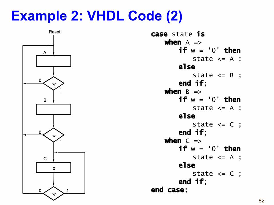
case state is when A =>
if w = '0' thenstate <= A ;
else
state <= B ;end if;
when B =>if w = '0' then
state <= A ;else
state <= C ;end if;
when C =>if w = '0' then
state <= A ;else
state <= C ;end if;
end case;
Example 2: VHDL Code (2)
w
w
w 0 1
0
1
0
1
A
B
C
z
Reset
w
w
w 0 1
0
1
0
1
A
B
C
z
Reset
83
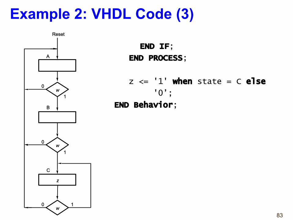
Example 2: VHDL Code (3)
END IF;
END PROCESS;
z <= '1' when state = C else
'0’;
END Behavior;
w
w
w 0 1
0
1
0
1
A
B
C
z
Reset
w
w
w 0 1
0
1
0
1
A
B
C
z
Reset
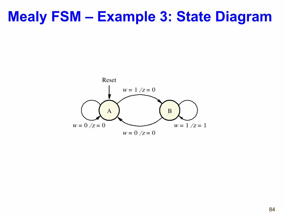
84
A
w 0 = z 0 = ⁄ w 1 = z 1 = ⁄
B
w 0 = z 0 = ⁄
Reset w 1 = z 0 = ⁄
Mealy FSM – Example 3: State Diagram
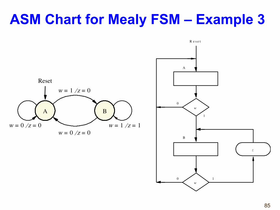
85
ASM Chart for Mealy FSM – Example 3
w
w 0 1
0
1
A
B
R e s e t
z
A
w 0 = z 0 = ⁄ w 1 = z 1 = ⁄
B
w 0 = z 0 = ⁄
Reset w 1 = z 0 = ⁄
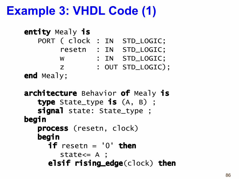
86
entity Mealy isPORT ( clock : IN STD_LOGIC;
resetn : IN STD_LOGIC;w : IN STD_LOGIC;z : OUT STD_LOGIC);
end Mealy;
architecture Behavior of Mealy istype State_type is (A, B) ;signal state: State_type ;
beginprocess (resetn, clock)begin
if resetn = '0' thenstate<= A ;
elsif rising_edge(clock) then
Example 3: VHDL Code (1)
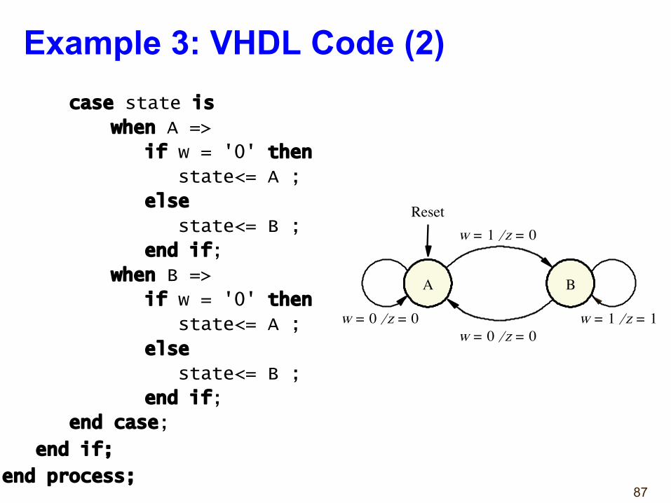
87
Example 3: VHDL Code (2)case state is
when A =>
if w = '0' then
state<= A ;
else
state<= B ;
end if;
when B =>
if w = '0' then
state<= A ;
else
state<= B ;
end if;
end case;
end if;
end process;
A
w 0 = z 0 = ⁄ w 1 = z 1 = ⁄
B
w 0 = z 0 = ⁄
Reset w 1 = z 0 = ⁄
88
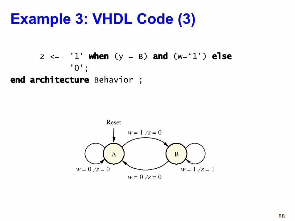
Example 3: VHDL Code (3)
z <= '1' when (y = B) and (w=‘1’) else
'0’;
end architecture Behavior ;
A
w 0 = z 0 = ⁄ w 1 = z 1 = ⁄
B
w 0 = z 0 = ⁄
Reset w 1 = z 0 = ⁄
89
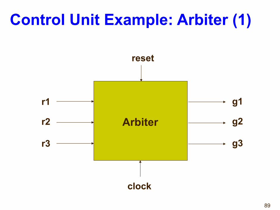
Control Unit Example: Arbiter (1)
Arbiter
reset
r1
r2
r3
g1
g2
g3
clock
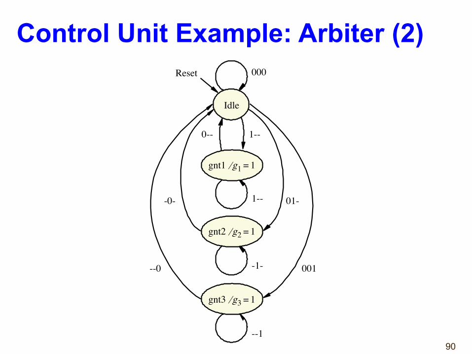
90
Idle
000
1--
Reset
gnt1 g 1 ⁄ 1 =
-1-
gnt2 g 2 ⁄ 1 =
--1
gnt3 g 3 ⁄ 1 =
0-- 1--
01--0-
001 --0
Control Unit Example: Arbiter (2)
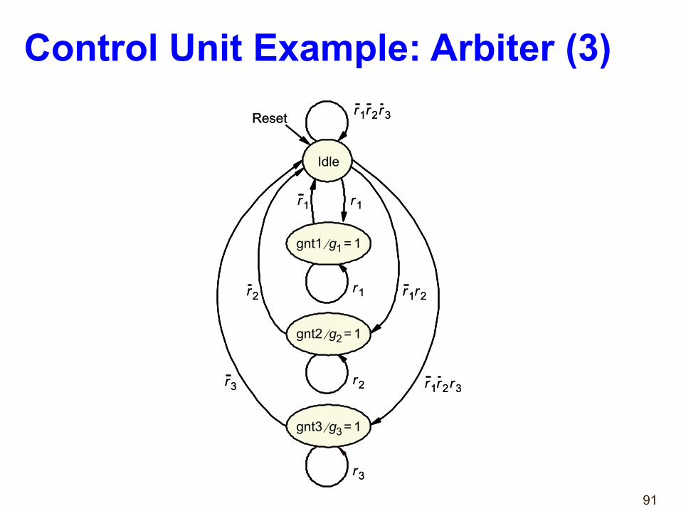
91
r 1 r 2
r 1 r 2 r 3
Idle
Reset
gnt1 g 1 ⁄ 1 =
gnt2 g 2 ⁄ 1 =
gnt3 g 3 ⁄ 1 =
r 1 r 1
r 1
r 2
r 3
r 2
r 3
r 1 r 2 r 3
r 1 r 2
r 1 r 2 r 3
Idle
Reset
gnt1 g 1 ⁄ 1 =
gnt2 g 2 ⁄ 1 =
gnt3 g 3 ⁄ 1 =
r 1 r 1
r 1
r 2
r 3
r 2
r 3
r 1 r 2 r 3
Control Unit Example: Arbiter (3)
92
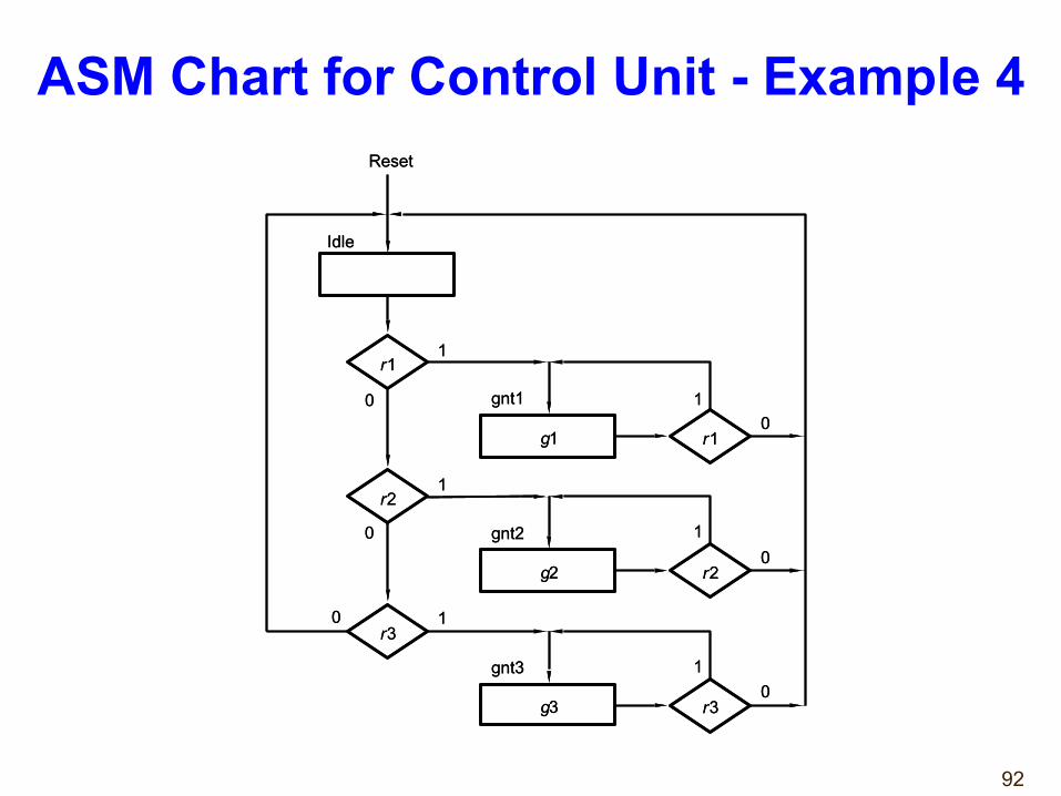
ASM Chart for Control Unit - Example 4
r 1
r 3 0 1
1
Idle
Reset
r 2
r 1
r 3
r 2
gnt1
gnt2
gnt3
1
1
1
0
0
0
g 1
g 2
g 3
0
0
1
r 1
r 3 0 1
1
Idle
Reset
r 2
r 1
r 3
r 2
gnt1
gnt2
gnt3
1
1
1
0
0
0
g 1
g 2
g 3
0
0
1
93
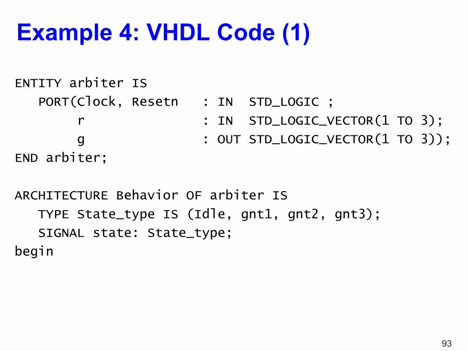
Example 4: VHDL Code (1)
ENTITY arbiter IS
PORT(Clock, Resetn : IN STD_LOGIC ;
r : IN STD_LOGIC_VECTOR(1 TO 3);
g : OUT STD_LOGIC_VECTOR(1 TO 3));
END arbiter;
ARCHITECTURE Behavior OF arbiter IS
TYPE State_type IS (Idle, gnt1, gnt2, gnt3);
SIGNAL state: State_type;
begin
94
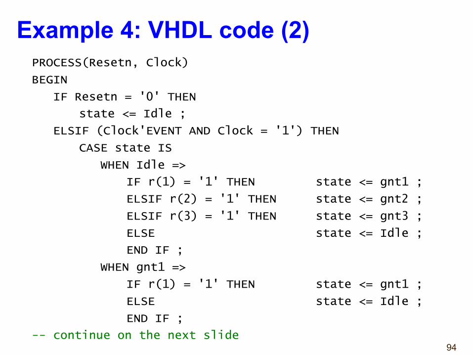
Example 4: VHDL code (2)PROCESS(Resetn, Clock)
BEGIN
IF Resetn = '0' THEN
state <= Idle ;
ELSIF (Clock'EVENT AND Clock = '1') THEN
CASE state IS
WHEN Idle =>
IF r(1) = '1' THEN state <= gnt1 ;
ELSIF r(2) = '1' THEN state <= gnt2 ;
ELSIF r(3) = '1' THEN state <= gnt3 ;
ELSE state <= Idle ;
END IF ;
WHEN gnt1 =>
IF r(1) = '1' THEN state <= gnt1 ;
ELSE state <= Idle ;
END IF ;
-- continue on the next slide
95
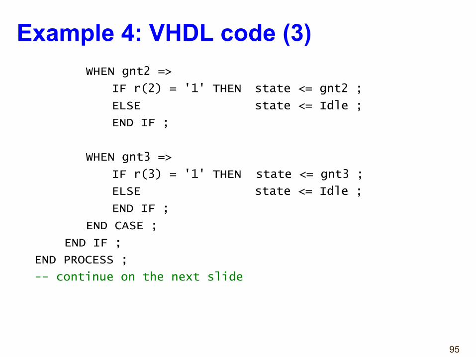
Example 4: VHDL code (3)WHEN gnt2 =>
IF r(2) = '1' THEN state <= gnt2 ;
ELSE state <= Idle ;
END IF ;
WHEN gnt3 =>
IF r(3) = '1' THEN state <= gnt3 ;
ELSE state <= Idle ;
END IF ;
END CASE ;
END IF ;
END PROCESS ;
-- continue on the next slide
96
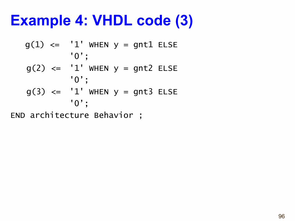
Example 4: VHDL code (3)g(1) <= '1' WHEN y = gnt1 ELSE
'0’;
g(2) <= '1' WHEN y = gnt2 ELSE
'0’;
g(3) <= '1' WHEN y = gnt3 ELSE
'0’;
END architecture Behavior ;
97
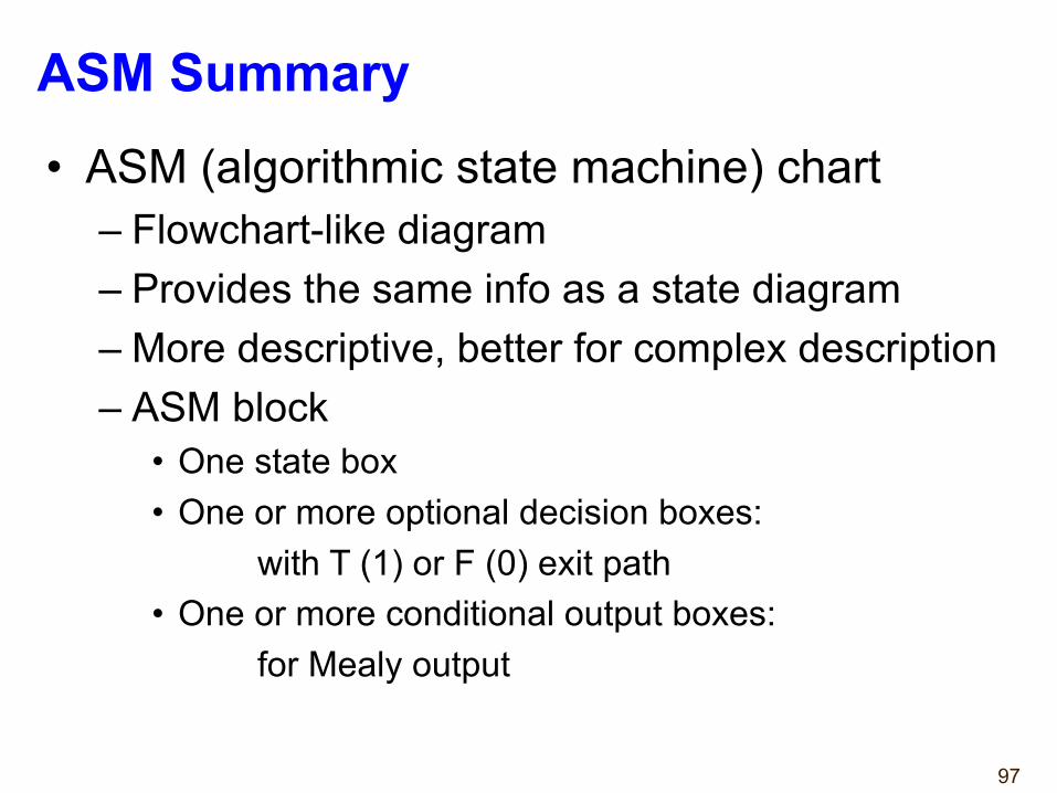
ASM Summary• ASM (algorithmic state machine) chart
– Flowchart-like diagram – Provides the same info as a state diagram– More descriptive, better for complex description– ASM block
• One state box• One or more optional decision boxes:
with T (1) or F (0) exit path• One or more conditional output boxes:
for Mealy output
98
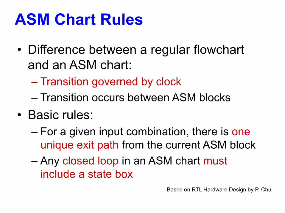
ASM Chart Rules
Based on RTL Hardware Design by P. Chu
• Difference between a regular flowchart and an ASM chart:– Transition governed by clock – Transition occurs between ASM blocks
• Basic rules:– For a given input combination, there is one
unique exit path from the current ASM block– Any closed loop in an ASM chart must
include a state box
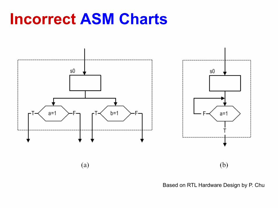
Incorrect ASM Charts
Based on RTL Hardware Design by P. Chu

Alternative Coding Stylesby Dr. Chu
(to be used with caution)

Traditional Coding Style
StateRegister
Next Statefunction
Moore Outputfunction
Inputs
Present State
Next State
clockreset
process(clock, reset)
concurrent statements
Mealy Outputfunction
Mealy Outputs Moore Outputs
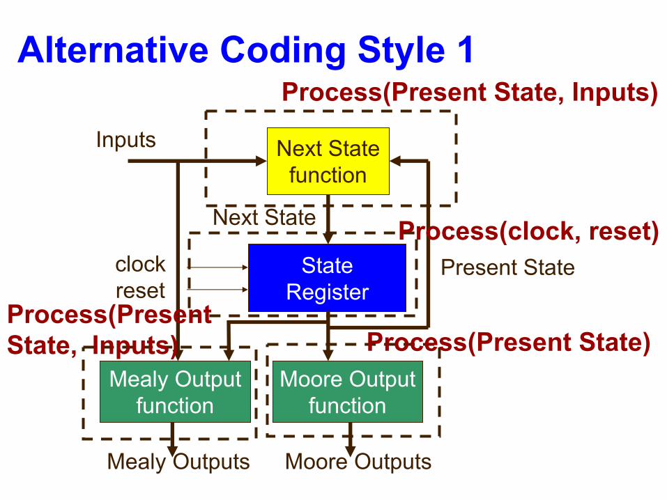
Alternative Coding Style 1
StateRegister
Next Statefunction
Moore Outputfunction
Inputs
Present State
Next State
clockreset
Process(Present State, Inputs)
Mealy Outputfunction
Mealy Outputs Moore Outputs
Process(clock, reset)
Process(Present State)Process(Present State, Inputs)
104
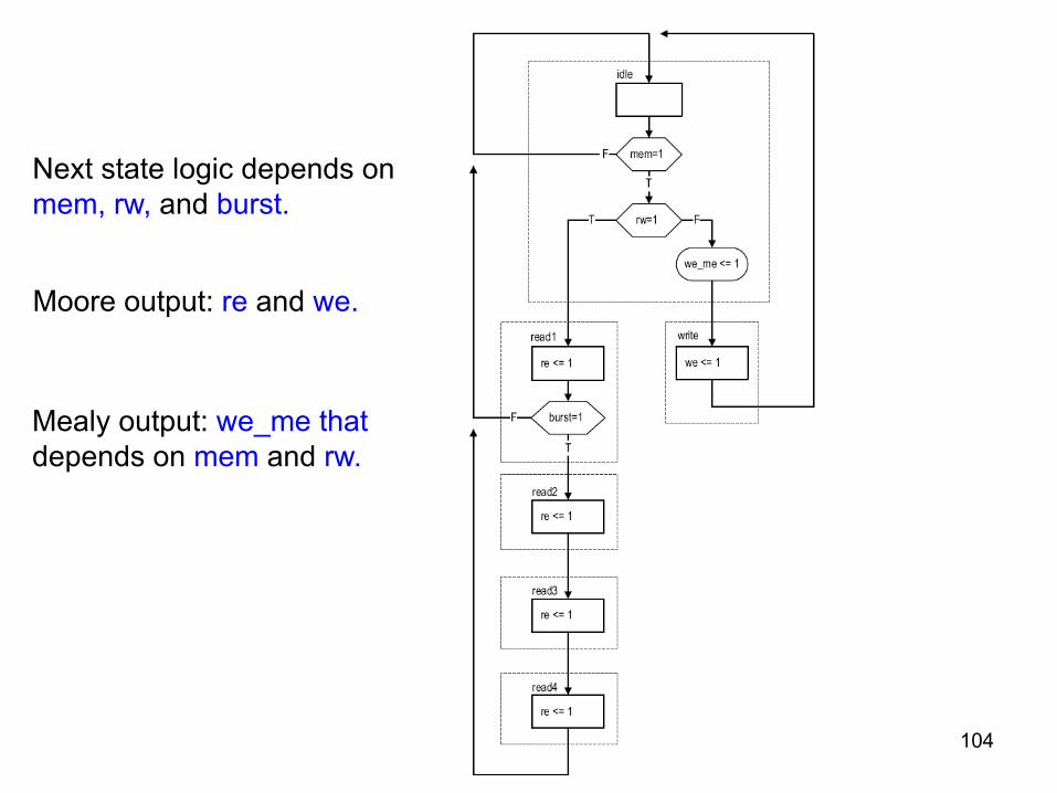
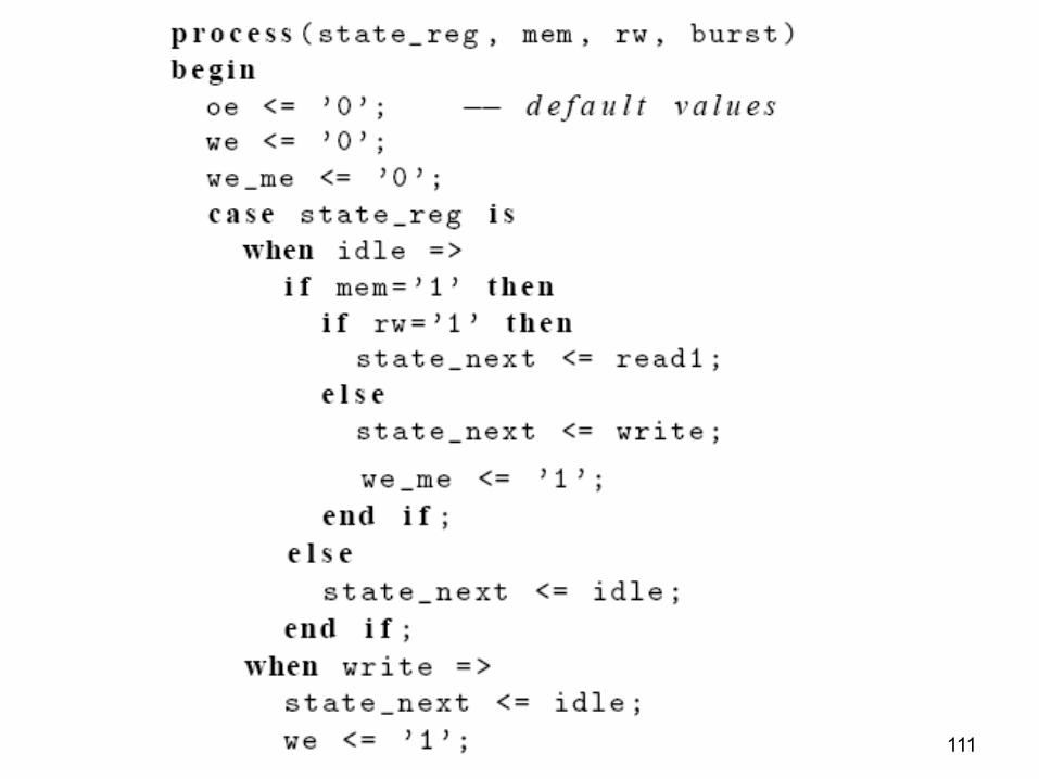
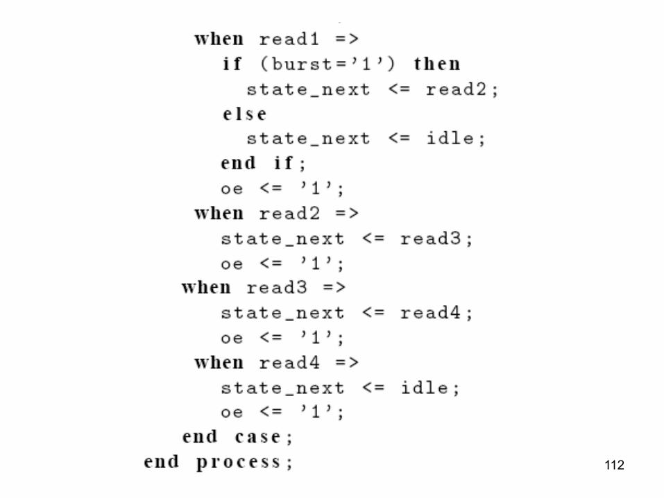
Next state logic depends on mem, rw, and burst.
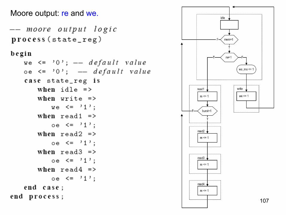
Moore output: re and we.
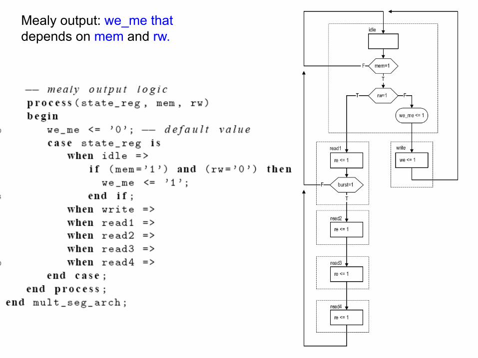
Mealy output: we_me that depends on mem and rw.

105
106
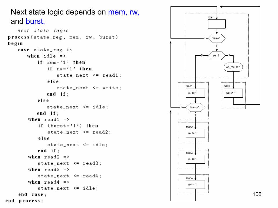
Next state logic depends on mem, rw, and burst.
107
Moore output: re and we.
108
Mealy output: we_me that depends on mem and rw.
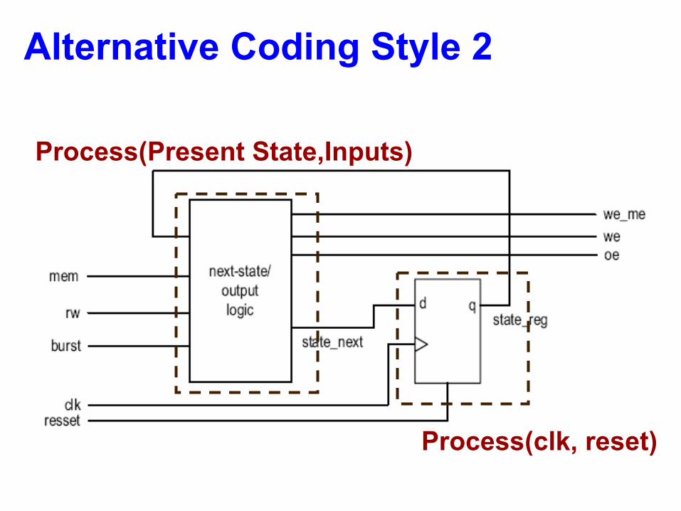
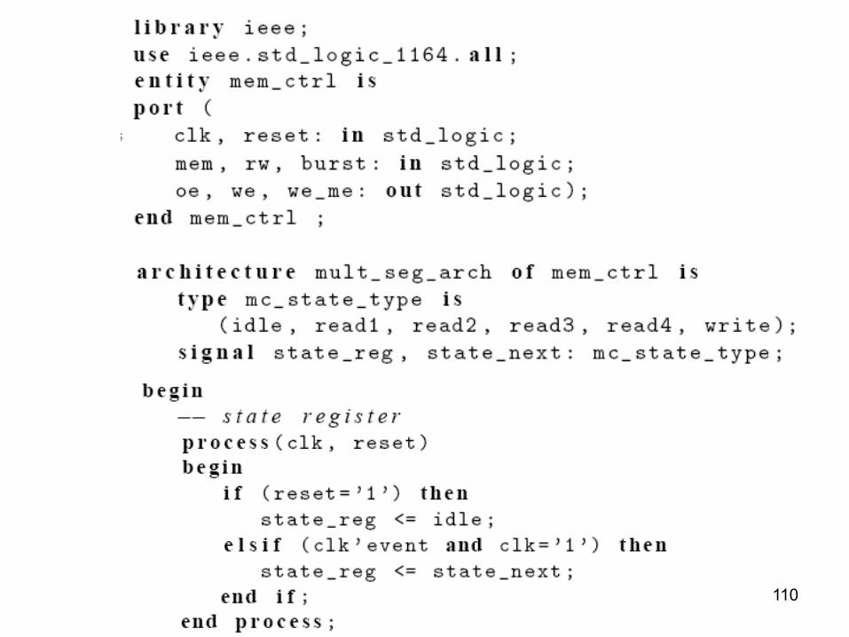
Alternative Coding Style 2
Process(clk, reset)
Process(Present State,Inputs)
110
111
112