Embed Size (px)
Citation preview

Part Number MN-CDM800 Revision 1
CDM-800 Advanced VSAT Series Gateway Router
Installation and Operation Manual For Firmware Version 1.3.2 or Higher
IMPORTANT NOTE: The information contained in this document supersedes all previously published information regarding this product. Product specifications are subject to change without prior notice.


Copyright © 2012 Comtech EF Data. All rights reserved. Printed in the USA. Comtech EF Data, 2114 West 7th Street, Tempe, Arizona 85281 USA, 480.333.2200, FAX: 480.333.2161
CDM-800 Advanced VSAT Series Gateway Router
Installation and Operation Manual For Firmware Version 1.3.2 or Higher
Part Number MN-CDM800
Revision 1

This page is intentionally blank.

ER-CDM800-EA1 Rev -
Errata A for MN-CDM800 Rev 1
Comtech EF Data Documentation Update
Subject: Added new safety information to Preface section
Errata Part Number: ER-CDM800-EA1 Rev - (Errata documents are not revised)
PLM CO Number: C-0035754
Comments: Replace Preface entirely.

ER-CDM800-EA1 Rev -
BLANK PAGE

ER-CDM800-EA1 Rev -
ER-CDM800-EA1 Rev -

ER-CDM800-EA1 Rev -

ER-CDM800-EA1 Rev -

ER-CDM800-EA1 Rev -

ER-CDM800-EA1 Rev -

iii
TABLE OF CONTENTS TABLE OF CONTENTS .............................................................................................................. III
TABLES ..................................................................................................................................... VII
FIGURES ................................................................................................................................... VII
PREFACE ................................................................................................................................... IX
About this Manual .............................................................................................................................. ix Reporting Comments or Suggestions Concerning this Manual ............................................................... ix Related Documents .................................................................................................................................. ix
Conventions and References ............................................................................................................... ix Patents and Trademarks .......................................................................................................................... ix Warnings, Cautions, and Notes ................................................................................................................. x Examples of Multi‐Hazard Notices ............................................................................................................ x Recommended Standard Designations ..................................................................................................... x Metric Conversion ..................................................................................................................................... x
Safety and Compliance ........................................................................................................................ xi Electrical Safety and Compliance ............................................................................................................. xi Electrical Installation ................................................................................................................................ xi Operating Environment ........................................................................................................................... xi European Union Radio Equipment and Telecommunications Terminal Equipment (R&TTE) Directive (1999/5/EC) and EN 301 489‐1 .............................................................................................. xi European Union Electromagnetic Compatibility (EMC) Directive (2004/108/EC) ........................ xii European Union Low Voltage Directive (LVD) (2006/95/EC) .............................................................. xii European Union RoHS Directive (2002/95/EC) ...................................................................................xiii European Union Telecommunications Terminal Equipment Directive (91/263/EEC) ........................xiii CE Mark ...............................................................................................................................................xiii
Warranty Policy ................................................................................................................................. xiv Limitations of Warranty .......................................................................................................................... xiv Exclusive Remedies ................................................................................................................................. xv
Getting Help ...................................................................................................................................... xvi Contacting Comtech EF Data .................................................................................................................. xvi Returning a Product for Upgrade or Repair ........................................................................................... xvii
CHAPTER 1. INTRODUCTION ............................................................................................. 1–1
1.1 Overview .............................................................................................................................. 1–1

CDM-800 Gateway Router Revision 1 Table of Contents MN-CDM800
iv
1.2 CDM‐800 Functional Description ........................................................................................... 1–2
1.3 CDM‐800 Features ................................................................................................................ 1–4 1.3.1 Physical Description .................................................................................................................. 1–4 1.3.2 Dimensional Envelope .............................................................................................................. 1–4 1.3.3 CDM‐800 Physical Features ...................................................................................................... 1–5 1.3.3.1 Front Panel ........................................................................................................................ 1–5 1.3.3.2 Rear Panel ......................................................................................................................... 1–6 1.3.3.2.1 Rear Panel Standard Features..................................................................................... 1–6 1.3.3.2.2 Rear Panel Optional Features ..................................................................................... 1–7
1.4 CDM‐800 Specifications ........................................................................................................ 1–8 1.4.1 Product Feature Specifications ................................................................................................. 1–8 1.4.2 Standard Assemblies................................................................................................................. 1–9 1.4.3 Optional Assemblies ................................................................................................................. 1–9 1.4.4 Regulatory Compliance ............................................................................................................. 1–9
CHAPTER 2. INSTALLATION .............................................................................................. 2–1
2.1 Unpacking and Inspection ..................................................................................................... 2–1
2.2 Installation into a Rack Enclosure ......................................................................................... 2–2 2.2.1 Installing the Optional Rear‐Mounting Support Brackets Kit ................................................... 2–4
CHAPTER 3. REAR PANEL CONNECTIONS ...................................................................... 3–1
3.1 Cabling Connection Types ..................................................................................................... 3–1 3.1.1 Coaxial Cable Connections ........................................................................................................ 3–1 3.1.1.1 Type ‘BNC’ ......................................................................................................................... 3–2 3.1.1.2 Type ‘TNC’ ......................................................................................................................... 3–2 3.1.1.3 Type ‘N’ ............................................................................................................................. 3–2 3.1.1.4 Type ‘F’ .............................................................................................................................. 3–3 3.1.1.5 Type ‘SMA’ (Subminiature Version ‘A’) ............................................................................. 3–3
3.1.2 D‐Subminiature Cable Connections .......................................................................................... 3–3 3.1.3 Circular Cable Connections ....................................................................................................... 3–4 3.1.4 RJ‐45, RJ‐48 Cable Connections ................................................................................................ 3–4
3.2 CDM‐800 Cabling Connections .............................................................................................. 3–5 3.2.1 IF Connector Group .................................................................................................................. 3–6 3.2.1.1 ‘L‐BAND Tx’ Connector ...................................................................................................... 3–6 3.2.1.2 ‘70/140 Tx’ IF Connector ................................................................................................... 3–6
3.2.2 Terrestrial Data Connector Group ............................................................................................ 3–7 3.2.2.1 ‘GE1’ ‘GE2’ (Gigabit Ethernet) Connectors ....................................................................... 3–7
3.2.3 ‘CLOCK EXTENSION IN’ Connector ............................................................................................ 3–7 3.2.4 Utility Connector Group ........................................................................................................... 3–8 3.2.4.1 ‘TERM’ Connector ............................................................................................................. 3–8 3.2.4.2 ‘FE’ (Fast Ethernet) Connector .......................................................................................... 3–8

CDM-800 Gateway Router Revision 1 Table of Contents MN-CDM800
v
3.2.4.3 ‘REDUNDANCY’ Connector ................................................................................................ 3–8 3.2.4.4 ‘CONSOLE’ Interface Connector ........................................................................................ 3–9
3.2.5 ‘(EXTERNAL) REFERENCE IN/OUT’ Connector ........................................................................... 3–9
3.3 CDM‐800 Ground and Power Connections .......................................................................... 3–10 3.3.1 Chassis Ground Interface ........................................................................................................ 3–10 3.3.2 115V/230V Alternating Current (AC) Power Interface (Standard) ......................................... 3–11 3.3.2.1 AC Operation – Applying Power ...................................................................................... 3–11 3.3.2.2 AC Operation – Replacing Fuses ..................................................................................... 3–12
3.3.3 48V Direct Current (DC) Power Interface (Optional) .............................................................. 3–13 3.3.3.1 DC Operation – Applying Power..................................................................................... 3–13 3.3.3.2 DC Operation – Replacing Fuses ..................................................................................... 3–14
CHAPTER 4. UPDATING FIRMWARE ................................................................................. 4–1
4.1 Updating Firmware via the Internet ...................................................................................... 4–1
4.2 Getting Started: Preparing for the Firmware Download ........................................................ 4–2
4.3 Downloading and Extracting the Firmware Update ............................................................... 4–6
4.4 Performing the Ethernet FTP Upload Procedure .................................................................... 4–8
CHAPTER 5. ETHERNET-BASED REMOTE PRODUCT MANAGEMENT ......................... 5–1
5.1 Introduction ......................................................................................................................... 5–1
5.2 Ethernet Management Interface Protocols ........................................................................... 5–2 5.2.1 Ethernet Management Interface Access .................................................................................. 5–2
5.3 SNMP Interface .................................................................................................................... 5–3 5.3.1 Management Information Base (MIB) Files .............................................................................. 5–3 5.3.2 SNMP Community Strings ......................................................................................................... 5–3
5.4 Web Server (HTTP) Interface ................................................................................................. 5–4 5.4.1 User Login ................................................................................................................................. 5–4 5.4.2 Web Server Interface – Operational Features .......................................................................... 5–5 5.4.2.1 Virtual Front Panel ............................................................................................................ 5–5 5.4.2.2 Navigation ......................................................................................................................... 5–5 5.4.2.3 Page Sections .................................................................................................................... 5–5 5.4.2.4 Execution Buttons ............................................................................................................. 5–5 5.4.2.5 Feature Selection .............................................................................................................. 5–6 5.4.2.6 Text or Data Entry ............................................................................................................. 5–6
5.4.3 Web Server Interface – Menu Tree .......................................................................................... 5–7 5.4.4 Web Server Interface Page Descriptions .................................................................................. 5–8 5.4.4.1 Home Pages ...................................................................................................................... 5–8 5.4.4.1.1 Home | Home ............................................................................................................. 5–8 5.4.4.1.2 Home | Contact .......................................................................................................... 5–9
CDM-800 Gateway Router Revision 1 Table of Contents MN-CDM800
vi
5.4.4.2 Admin (Administration) Pages ........................................................................................ 5–10 5.4.4.2.1 Admin | Access ......................................................................................................... 5–10 5.4.4.2.2 Admin | SNMP .......................................................................................................... 5–11 5.4.4.2.3 Admin | FAST ............................................................................................................ 5–12 5.4.4.2.4 Admin | Firmware ..................................................................................................... 5–14 5.4.4.2.5 Admin | Auto Logout ................................................................................................ 5–15 5.4.4.2.6 Admin | VMS ............................................................................................................. 5–16
5.4.4.3 Configuration Pages ........................................................................................................ 5–18 5.4.4.3.1 Configuration | Interface .......................................................................................... 5–18 5.4.4.3.1.1 Configuration | Interface | FE Mgt .................................................................... 5–18 5.4.4.3.1.2 Configuration | Interface | GE‐1 or GE‐2 ........................................................... 5–19
5.4.4.3.2 Configuration | Mod (Modulator) ............................................................................ 5–20 5.4.4.3.3 Configuration | ARP .................................................................................................. 5–22 5.4.4.3.4 Configuration | Routing | Routes ............................................................................. 5–23 5.4.4.3.5 Configuration | Compression ................................................................................... 5–25 5.4.4.3.5.1 Configuration | WAN | QoS ............................................................................... 5–26
5.4.4.4 Status Pages .................................................................................................................... 5–34 5.4.4.4.1.1 Status | Statistics | Traffic ................................................................................. 5–34 5.4.4.4.1.2 Status | Statistics | Router ................................................................................. 5–36 5.4.4.4.1.3 Status | Statistics | Compression....................................................................... 5–37 5.4.4.4.1.4 Status | Statistics | QoS ..................................................................................... 5–38 5.4.4.4.1.5 Status | Statistics | VCM (Variable Coding and Modulation) ............................ 5–41
5.4.4.4.2 Status | Monitor page ............................................................................................... 5–43 5.4.4.5 Utility Pages .................................................................................................................... 5–44 5.4.4.5.1 Utility | Utility ........................................................................................................... 5–44 5.4.4.5.2 Utility | Reboot ......................................................................................................... 5–47
CHAPTER 6. SERIAL-BASED REMOTE PRODUCT MANAGEMENT ................................ 6–1
6.1 Introduction ......................................................................................................................... 6–1
6.2 Remote Commands and Queries Overview ........................................................................... 6–3 6.2.1 Basic Protocol ........................................................................................................................... 6–3 6.2.2 Packet Structure ....................................................................................................................... 6–3 6.2.2.1 Start of Packet ................................................................................................................... 6–4 6.2.2.2 Target Address .................................................................................................................. 6–5 6.2.2.3 Address Delimiter .............................................................................................................. 6–5 6.2.2.4 Instruction Code ................................................................................................................ 6–5 6.2.2.5 Instruction Code Qualifier ................................................................................................. 6–6 6.2.2.6 Optional Message Arguments ........................................................................................... 6–7 6.2.2.7 End of Packet .................................................................................................................... 6–7
6.3 Remote Commands and Queries ........................................................................................... 6–8
APPENDIX A. FAST ............................................................................................................. A–1
A.1 FAST Overview ..................................................................................................................... A–1

CDM-800 Gateway Router Revision 1 Table of Contents MN-CDM800
vii
A.2 FAST Activation via the Web Server Interface ....................................................................... A–2
APPENDIX B. FEC (FORWARD ERROR CORRECTION) ..................................................... B–1
B.1 Introduction ......................................................................................................................... B–1
B.2 DVB‐S2: LDPC and BCH .......................................................................................................... B–1 B.2.1 Range of Data Rates.................................................................................................................. B–1 B.2.2 BER, QEF, Eb/No, Es/No Spectral Efficiency, and Occupied Bandwidth .......................................... B–1
B.3 CDM‐800 Error Performance Characteristics ......................................................................... B–2
TABLES Table 3‐1. REDUNDANCY Connector Pinout ............................................................................................ 3–8 Table 3‐2. CONSOLE Connector Pinout .................................................................................................... 3–9
FIGURES Figure 1‐1. CDM‐800 Gateway Router ...................................................................................................... 1–1 Figure 1‐2. Advanced VSAT Series Network Topology Example ............................................................... 1–1 Figure 1‐3. CDM‐800 Dimensional Envelope ............................................................................................ 1–4 Figure 1‐4. CDM‐800 – Front Panel View .................................................................................................. 1–5 Figure 1‐5. CDM‐800 – Rear Panel View ................................................................................................... 1–6 Figure 2‐1. Unpacking and Inspecting the Shipment ................................................................................ 2–1 Figure 2‐2. Installation into a Rack Enclosure ........................................................................................... 2–3 Figure 2‐3. Installation of Optional Rear‐Mounting Support Brackets Kit ............................................... 2–5 Figure 3‐1. Coaxial Connector Examples ................................................................................................... 3–1 Figure 3‐2. D‐Subminiature Connector Examples ..................................................................................... 3–3 Figure 3‐3. CDM‐800 Cabling Connections ............................................................................................... 3–5 Figure 3‐4. CDM‐800 Chassis Ground Interface ...................................................................................... 3–10 Figure 3‐5. CDM‐800 AC Power Interface ............................................................................................... 3–11 Figure 3‐6. Applying AC Power to the CDM‐800 ..................................................................................... 3–11 Figure 3‐7. Replacing CDM‐800 AC Fuses ............................................................................................... 3–12 Figure 3‐8. CDM‐800 DC Power Interface ............................................................................................... 3–13 Figure 3‐9. Applying DC Power to the CDM‐800 ..................................................................................... 3–13 Figure 3‐10. Replacing CDM‐800 DC Fuses ............................................................................................. 3–14 Figure 5‐1. Home | Home page ................................................................................................................ 5–8 Figure 5‐2. Home | Contact page .............................................................................................................. 5–9 Figure 5‐3. Admin | Access page............................................................................................................. 5–10 Figure 5‐4. Admin | SNMP page ............................................................................................................. 5–11 Figure 5‐5. Admin | FAST page ............................................................................................................... 5–12

CDM-800 Gateway Router Revision 1 Table of Contents MN-CDM800
viii
Figure 5‐6. Admin | Firmware page ........................................................................................................ 5–14 Figure 5‐7. Admin | Auto Logout page ................................................................................................... 5–15 Figure 5‐8. Admin | VMS page ................................................................................................................ 5–16 Figure 5‐9. Configuration | Interface | FE Mgt Page .............................................................................. 5–18 Figure 5‐10. Configuration | Interface | GE‐1 or GE‐2 Page ................................................................... 5–19 Figure 5‐11. Configuration | Mod page .................................................................................................. 5–20 Figure 5‐12. Configuration | ARP page ................................................................................................... 5–22 Figure 5‐13. Configuration | Routing | Routes page .............................................................................. 5–23 Figure 5‐14. Configuration | Compression page ..................................................................................... 5–25 Figure 5‐15. Configuration | WAN | QoS page ....................................................................................... 5–26 Figure 5‐16. Configuration | WAN | QoS page (continued) ................................................................... 5–27 Figure 5‐17. Status | Statistics | Traffic page.......................................................................................... 5–34 Figure 5‐18. Status | Statistics | Router page ......................................................................................... 5–36 Figure 5‐19. Status | Statistics | Compression page ............................................................................... 5–37 Figure 5‐20. Status | Statistics | QoS page ............................................................................................. 5–38 Figure 5‐21. Status | Statistics | VCM page ............................................................................................ 5–41 Figure 5‐22. Status | Monitor page ........................................................................................................ 5–43 Figure 5‐23. Utility | Utility page ............................................................................................................ 5–44 Figure 5‐24. Utility | Reboot page .......................................................................................................... 5–47 Figure 5‐1. CDM‐800 Serial Interface Example ......................................................................................... 6–2 Figure A‐1. CDM‐800 Web Server (HTTP) Interface – ‘ADMIN | FAST’ page ............................................ A–2 Figure B‐1. DVB‐S2 QPSK Packet Error Rate versus Es/No ........................................................................ B–3 Figure B‐2. DVB‐S2 8PSK Packet Error Rate versus Es/No ........................................................................ B–4 Figure B‐3. DVB‐S2 16APSK Packet Error Rate versus Es/No .................................................................... B–5 Figure B‐4. DVB‐S2 32APSK Packet Error Rate versus Es/No .................................................................... B–6
1–1
Chapter 1. INTRODUCTION
1.1 Overview
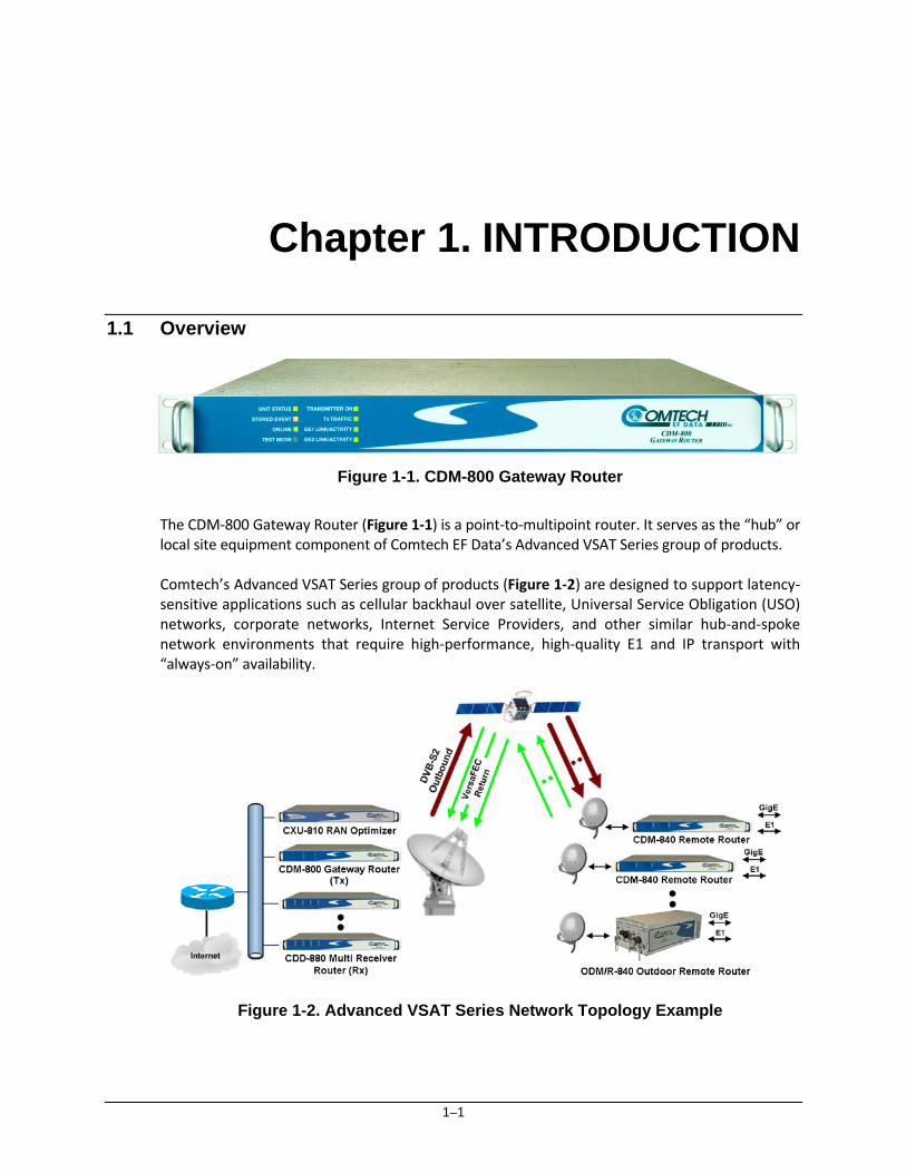
Figure 1-1. CDM-800 Gateway Router The CDM‐800 Gateway Router (Figure 1‐1) is a point‐to‐multipoint router. It serves as the “hub” or local site equipment component of Comtech EF Data’s Advanced VSAT Series group of products. Comtech’s Advanced VSAT Series group of products (Figure 1‐2) are designed to support latency‐sensitive applications such as cellular backhaul over satellite, Universal Service Obligation (USO) networks, corporate networks, Internet Service Providers, and other similar hub‐and‐spoke network environments that require high‐performance, high‐quality E1 and IP transport with “always‐on” availability.
Figure 1-2. Advanced VSAT Series Network Topology Example

CDM-800 Gateway Router Revision 1 Introduction MN-CDM800
1–2
The CDM‐800 features two 10/100/1000 Gigabit Ethernet (GigE) interfaces, one 10/100 Fast Ethernet (FE) interface, and provides WAN bandwidth optimization. The unit also features DVB‐S2 FEC coding.
• Sect. 1.3 CDM‐800 Features • Sect. 1.4 CDM‐800 Specifications
1.2 CDM-800 Functional Description
The CDM‐800 Gateway Router:
• Is compatible with Comtech EF Data’s CDM‐840 Remote Router for Variable Coding and Modulation (VCM) operation.
• Features a high performance processor and a real‐time operating system (RTOS) combined with multiple Field Programmable Gate Arrays (FPGAs).
• Runs on an embedded operating system in non‐volatile Flash memory. It does not have moving parts for media storage.
• Supports reception and transmission of IP data over satellite links via two fundamentally different types of interface – IF and data:
o The IF interface provides uplink connectivity with the satellite.
o The data interface is a bidirectional path that connects the customer’s equipment
(assumed to be the Data Terminal Equipment, or DTE) to the unit (assumed to be the Data Communications Equipment, or DCE). All terrestrial data is connected using the available 10/100/1000 Gigabit Ethernet interface.
DVB‐S2 Transmitter: The CDM‐800’s modulator supports enhanced GSE encapsulation and label filtering insertion for up to 2,047 unique labels. It supports DVB‐S2 QPSK, 8‐PSK, 16‐APSK and 32‐APSK modulation up to 62 Msps with transmit data rates up to 160 Mbps depending on the modulation type and code rate, In DVB‐S2 operation, the transmitter operates in the VCM mode. The receive modem automatically detects for spectral inversion pilots ON/OFF, spectral rolloff of 20%, 25% or 35%, frame size NORMAL/SHORT, and can also be configured to automatically detect the modulation coding (MODCOD).
• Sect. 1.3 CDM‐800 Features • Sect. 1.4 CDM‐800 Specifications • Appendix B. FEC (FORWARD ERROR CORRECTION)
The unit is managed through multiple interfaces providing options for both in‐band and out‐of‐band monitor and control:

CDM-800 Gateway Router Revision 1 Introduction MN-CDM800
1–3
• Sect. 5.3 (ETHERNET‐BASED PRODUCT MANAGEMENT) SNMP (MIB II and Private MIB)
• Sect. 5.4 (ETHERNET‐BASED PRODUCT MANAGEMENT) Web Server (HTTP) Interface
• Chapter 6. SERIAL‐BASED REMOTE PRODUCT MANAGEMENT
Field update of the operating system firmware is possible through file upload via satellite or the Ethernet port.
Chapter 4. UPDATING FIRMWARE
Field activation of software‐based options is possible through Comtech’s FAST (Fully Accessible System Topology) Feature upgrade process.
• Sect. 5.4.4.2.3 (CDM‐800 Web Server Interface) Admin | FAST Page • Appendix A. FAST

CDM-800 Gateway Router Revision 1 Introduction MN-CDM800
1–4
1.3 CDM-800 Features
1.3.1 Physical Description
The CDM‐800 Gateway Router is constructed as a 1RU‐high rack‐mounting chassis. Handles at the front facilitate removal from and placement into a rack. The unit can be free‐standing if desired.
• Sect. 1.4 CDM‐800 Product Specifications • Sect. 2.1 Installation into a Rack Enclosure
1.3.2 Dimensional Envelope
Figure 1-3. CDM-800 Dimensional Envelope

CDM-800 Gateway Router Revision 1 Introduction MN-CDM800
1–5
1.3.3 CDM-800 Physical Features
1.3.3.1 Front Panel
Figure 1-4. CDM-800 – Front Panel View The front panel of the CDM‐800 (Figure 1‐4) features eight Light‐Emitting Diode (LED) indicators. These LEDs convey operational states as follows: LED Condition
UNIT STATUS
Green No Unit Faults or Alarms.
Amber No Unit Faults, but an Alarm exists.
Red A Unit Fault exists (Example: PSU fault).
STORED EVENT Amber
There is a Stored Event in the log, which can be viewed from the Web Server Interface or retrieved via the SNMP interface.
Off There are no Stored Events.
ONLINE Green The Unit is On Line, and carrying traffic.
Off The Unit is Off Line (standby – forced by externally connected 1:1 or 1:N Redundancy System).
TEST MODE Amber A Test Mode is selected (Example: CW).
Off There is no Test Mode currently selected.
TRANSMITTER ON
Green The Transmitter Carrier is On.
Off The Transmitter Carrier is Off.
Tx TRAFFIC
Green (solid) No Tx Traffic Faults, no packets.
Green (blinking)
No Tx Traffic Faults, blinks when a packet is being transmitted to the satellite link from this unit.
Off A Tx Traffic Fault exists.
GE1 or GE2 LINK/ACTIVITY
Green (solid) Traffic Ethernet is connected, but no traffic exists.
Green (blinking)
Ethernet activity detected.
Off Traffic Ethernet is not connected.

CDM-800 Gateway Router Revision 1 Introduction MN-CDM800
1–6
1.3.3.2 Rear Panel
PROPER GROUNDING PROTECTION IS REQUIRED. The equipment must be connected to the protective earth connection at all times. It is therefore imperative that the unit is properly grounded, using the ground stud provided on the unit rear panel, during installation, configuration, and operation.
• Sect. 3.2 CDM‐800 Cabling Connections • Sect. 3.3 CDM‐800 Grounding and Power Connections
External cables are attached to connectors provided on the rear panel of the unit (Figure 1‐5).
Figure 1-5. CDM-800 – Rear Panel View
1.3.3.2.1 Rear Panel Standard Features
The unit provides the following standard interfaces: Data Interfaces:
• (2X) 10/100/1000 BaseT Gigabit Ethernet RJ‐45 Interfaces (GE1, GE2 ports) for Ethernet traffic.
• (1X) 10/100 BaseT Fast Ethernet RJ‐45 Interface (FE port) for HTTP and SNMP management and control purposes (Web and SNMP).
• (1X) DB‐9F EIA‐232 connector for serial remote control (CONSOLE port). Tx (Transmit) IF Interfaces
• (1X) Type ‘N’ female connector for 50Ω L‐Band (950 to 2150 MHz)
• (1X) Type ‘BNC’ female connector for 62Ω 70/140 MHz Power Interface
• 115/230 VAC Primary Input Power Supply with Press‐fit Fuse Holder
(Top) Standard AC Unit (Bottom) Optional 48V DC Unit

CDM-800 Gateway Router Revision 1 Introduction MN-CDM800
1–7
1.3.3.2.2 Rear Panel Optional Features
The unit provides the following Data Interface for optional hardware operation:
• (1X) DB‐9M EIA‐232 connector labeled “REDUNDANCY” for interoperability with a separately purchased Comtech EF Data CRS‐170A 1:1 Redundancy Switch for L‐Band operation, or the CRS‐180 1:1 Redundancy Switch for 70/140 MHz operation. M:N device redundancy support is available with the separately purchased Vipersat Management System (VMS).
The following Power Interface Option is available from Comtech EF Data:
• 48 VDC Primary Input Power Supply with Screw‐in Fuse Holders
The following installation kits are available from Comtech EF Data:
• KT/6228‐2 4” Rear‐Mounting Support Brackets Kit
• KT/6228‐3 10” Rear‐Mounting Support Brackets Kit
Sect. 2.2.1 Installing the Optional Rear‐Mounting Support Brackets Kit

CDM-800 Gateway Router Revision 1 Introduction MN-CDM800
1–8
1.4 CDM-800 Specifications
1.4.1 Product Feature Specifications
Specification Description
Front Panel
8 Light-emitting Diodes (LEDs): • UNIT STATUS (Green/Orange/Red) • STORED EVENT (Amber) • ONLINE (Green) • TEST MODE (Amber)
• TRANSMITTER ON (Green) • Tx TRAFFIC (Green) • GE1 LINK/ACTIVITY (Green) • GE2 Link Activity (Green)
Data Interfaces • (2X) 10/100/1000 BaseT Gigabit Ethernet (traffic) • (1X) 10/100 BaseT Fast Ethernet (management and control) • EIA-232 interface for router serial remote control
Dimensional Envelope 19.0 W x 18.15 D x 1 RU (1.7) H inches (483 W x 461 D x 44 H mm)
Temperature Operating 32° to 122°F (0° to 50°C)
Storage -4° to 158°F (–20° to 70°C)
Humidity 95% maximum, non-condensing
Tx Operating Frequency • 950 – 2150 MHz • 50 – 180 MHz
Tx Connectors & Impedance • Type-N Female, 50Ω • BNC Female, 62Ω
Power Supply
AC 100-240 VAC, 47 Hz-63 Hz
DC (HW option) 48V (36V to 60V) DC
Transmit Power • -5 to -40 dBm (950 – 2150 MHz) • -5 to -25 dBm (50 – 180 MHz)
Supported Protocols
• RFC 768 – UDP • RFC 791 – IP • RFC 792 – ICMP • RFC 793 – TCP • RFC 826 – ARP • RFC 856 – Telnet • RFC 862 – Ping • RFC 894 – IP
• RFC 959 – FTP • RFC 1112 – IP Multicast • RFC 1213 – SNMP MIB II • RFC 1812 – IPv4 Routers • RFC 2045 – MIME • RFC 2474 – DiffServ • RFC 2475 – DiffServ • RFC 2578 – SMI
• RFC 2597 – AF PHB • RFC 2598 – Expedite Forwarding • RFC 2616 – HTTP • RFC 3412 – SNMP • RFC 3416 – SNMPv2 • RFC 3418 – SNMP MIB
Data Rate 1 – 168 Mbps
Symbol Rate • 1 – 62 Msps (QPSK, 8-PSK) • 1 – 47 Msps (16-APSK) • 1 – 37 Msps (32-APSK)
FEC DVB-S2
Modulation and Code Rates
• QPSK 1/4, 1/3, 2/5, 1/2, 3/5, 2/3, 3/4, 4/5, 5/6, 8/9, 9/10* • 8-PSK 3/5, 2/3, 3/4, 5/6, 8/9, 9/10* • 16-APSK 2/3, 3/4, 4/5, 5/6, 8/9, 9/10* • 32-APSK 3/4, 4/5, 5/6, 8/9, 9/10* *Note: Frame Type defaults to NORMAL if any MODCOD in Group QoS has a code rate of 9/10
Rolloff 20%, 25% and 35%
Encapsulation Enhanced GSE
CDM-800 Gateway Router Revision 1 Introduction MN-CDM800
1–9
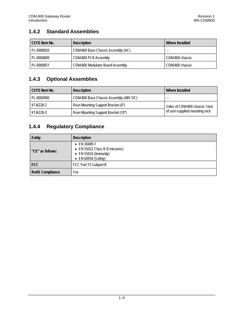
1.4.2 Standard Assemblies
CEFD Item No. Description Where Installed
PL-0000820 CDM-800 Base Chassis Assembly (AC) –
PL-0000809 CDM-800 PCB Assembly CDM-800 chassis
PL-0000851 CDM-800 Modulator Board Assembly CDM-800 chassis
1.4.3 Optional Assemblies
CEFD Item No. Description Where Installed
PL-0000900 CDM-800 Base Chassis Assembly (48V DC) –
KT/6228-2 Rear-Mounting Support Bracket (4”) Sides of CDM-800 chassis / rear of user-supplied mounting rack KT/6228-3 Rear-Mounting Support Bracket (10”)
1.4.4 Regulatory Compliance
Entity Description
“CE” as follows:
• EN 30489-1 • EN 55022 Class B (Emissions) • EN 55024 (Immunity) • EN 60950 (Safety)
FCC FCC Part 15 Subpart B
RoHS Compliance Yes

CDM-800 Gateway Router Revision 1 Introduction MN-CDM800
1–10
Notes:

2–1
Chapter 2. INSTALLATION
2.1 Unpacking and Inspection
Figure 2-1. Unpacking and Inspecting the Shipment The CDM‐800 Gateway Router, its Installation and Operation Manual, and its power cord were packaged and shipped in a reusable cardboard carton containing protective foam spacing.
This equipment contains parts and assemblies sensitive to damage by Electrostatic Discharge (ESD). Use ESD precautionary procedures when handling the equipment.

CDM-800 Gateway Router Revision 1 Installation MN-CDM800
2–2
Once opened, inspect the shipment:
Step Task
1 Keep all shipping materials for storage or reshipment.
2 Check the packing list to ensure the shipment is complete.
3 Inspect the equipment for any possible damage incurred during shipment. Contact the carrier and Comtech EF Data immediately to submit a damage report if damage is evident.
4 Review this CDM‐800 Gateway Router Installation and Operation Manual
carefully to become familiar with operation.
5
Proceed to Sect. 2.2 Installation into a Rack Enclosure.
2.2 Installation into a Rack Enclosure
When mounting the CDM‐800 into a rack enclosure (Figure 2‐2):
• PROPER GROUNDING PROTECTION IS REQUIRED. The equipment must be connected to the protective earth connection at all times. It is therefore imperative that the unit is properly grounded, using the ground stud provided on the unit rear panel, during installation, configuration, and operation.
• PROPER AIR VENTILATION IS REQUIRED. In a rack system where there is high heat discharge, provide forced‐air cooling with top‐ or bottom‐mounted fans or blowers.
o Make sure there is adequate clearance inside the enclosure, especially at the side for air ventilation.
o Air temperature inside the rack enclosure should never exceed 50°C (122°F).
For information about custom rack enclosures, contact Comtech EF Data Customer Support during normal business hours or visit Comtech EF Data’s Web site (www.comtechefdata.com/support.asp).
• The CDM‐800 CANNOT have rack slides mounted to the sides of the chassis.
Cooling fans and exhaust vents are provided here – air flow must not be impeded. Comtech EF Data recommends that an alternate method of support is provided within the rack, such as standard rack shelves or the optional Rear‐Mounting Support Bracket Kit. If there is any doubt, contact Comtech EF Data Customer Support during normal business hours.
CDM-800 Gateway Router Revision 1 Installation MN-CDM800
2–3
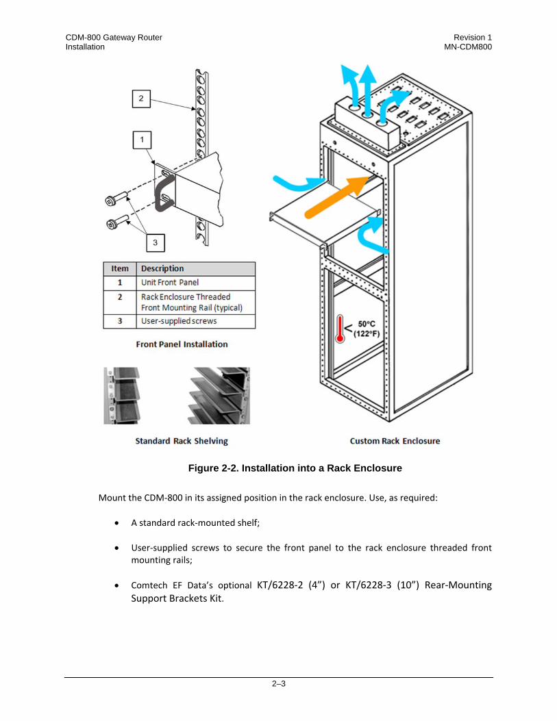
Figure 2-2. Installation into a Rack Enclosure
Mount the CDM‐800 in its assigned position in the rack enclosure. Use, as required:
• A standard rack‐mounted shelf;
• User‐supplied screws to secure the front panel to the rack enclosure threaded front mounting rails;
• Comtech EF Data’s optional KT/6228‐2 (4”) or KT/6228‐3 (10”) Rear‐Mounting Support Brackets Kit.

CDM-800 Gateway Router Revision 1 Installation MN-CDM800
2–4
2.2.1 Installing the Optional Rear-Mounting Support Brackets Kit
Tools needed to install the KT/6228‐2 (4”) or KT/6228‐3 (10”) Bracket Kit:
• A medium Phillips™ screwdriver
• A 5/32‐inch SAE Allen™ Wrench
• An adjustable Crescent™ wrench. To install the CEFD Chassis‐Style kit:
Step Task
1 Use the #10 flat washers, #10 split washers, and #10 hex nuts to secure the #10 shoulder screws to the unit chassis through the rear right and left side mounting slots.
2 Use the #10 rack bracket bolts to install the rear support brackets onto the rack enclosure threaded rear mounting rails.
3 Mount the unit into the rack enclosure. Ensure that the shoulders of the #10 shoulder screws properly engage into the rear support bracket slots.

CDM-800 Gateway Router Revision 1 Installation MN-CDM800
2–5
Item Kit / Quantity
Part Number Description KT/6228‐2 KT/6228‐3
1 2 2 HW/10‐32SHLDR Shoulder Screw, #10
2 4 4 HW/10‐32FLT Flat Washer, #10
3 2 2 HW/10‐32SPLIT Lock Washer, #10
4 2 2 HW/10‐32HEXNUT Hex Nut, #10
5 4 4 HW/10‐32x1/2RK Bolt, #10, Rear Support Bracket
6 2 – FP/6138‐2 Bracket, Rear Support – 4”
– 2 FP/6138‐3 Bracket, Rear Support – 10”
Figure 2-3. Installation of Optional Rear-Mounting Support Brackets Kit
Detail Description
1 Back of Unit
2 Rack Enclosure Threaded Rear Mounting Rail (typical)

CDM-800 Gateway Router Revision 1 Installation MN-CDM800
2–6
Notes:

3–1
Chapter 3. REAR PANEL CONNECTIONS
3.1 Cabling Connection Types
The CDM‐800 Gateway Router uses a number of different cables. Each cable type is typically dedicated to a specific mode of operation.
Not all of these operational interface types may be available with this product.
3.1.1 Coaxial Cable Connections
Coupling Type Connector Type
Plug Jack
Bayonet (Type ‘BNC’ shown)
Threaded (Type ‘N’ shown)
Figure 3‐1. Coaxial Connector Examples
The types of coaxial cables used by Comtech EF Data are ‘BNC’, ‘TNC’, ‘N’, ‘F’, and ‘SMA’. Coaxial cables (plugs) and their mating connectors (jacks/sockets) are available in two coupling styles: Bayonet or Threaded.

CDM-800 Gateway Router Revision 1 Rear Panel Connections MN-CDM800
3–2
• Bayonet Coupling Style: The jack has a pair of guide posts that accommodate the plug’s
lockdown slots. This lockdown design provides secure assembly without over‐tightening the connection.
• Threaded Coupling Style: The jack features external threads. The plug shell features
internal threads, and has either a knurled outer surface to permit hand‐tightening of the connection, or hex flats to accommodate torqued installation.
Connection Instructions:
• Bayonet Coupling Connections: Use the plug slots to guide, then slide the plug onto the jack posts. Then, turn the plug clockwise until the jack posts are fully seated within the plug slot.
• Threaded Coupling Connections: Engage the plug onto the jack threads, and then turn
the plug clockwise until it is fully threaded onto the jack. Do not over‐tighten the connection.
3.1.1.1 Type ‘BNC’
BNC plugs and jacks feature a Bayonet Coupling design.
3.1.1.2 Type ‘TNC’
TNC plugs and jacks feature a Threaded Coupling design similar to Type ‘N’, Type ‘F,’ and Type ‘SMA’ connectors.
3.1.1.3 Type ‘N’
Type ‘N’ connectors feature a Threaded Coupling design similar to Type ‘TNC’, Type ‘F’, and Type ‘SMA’ connectors.

CDM-800 Gateway Router Revision 1 Rear Panel Connections MN-CDM800
3–3
3.1.1.4 Type ‘F’
Type ‘F’ connectors feature a Threaded Coupling design similar to Type ‘TNC’, Type ‘N’, and Type ‘SMA’ connectors.
3.1.1.5 Type ‘SMA’ (Subminiature Version ‘A’)
Type ‘SMA’ connectors feature a Threaded Coupling design similar to Type ‘TNC’, Type ‘N’, and Type ‘F’ connectors.
3.1.2 D-Subminiature Cable Connections
Type ‘D’ Connection Type Example
Chassis Receptacles: Female (top) Male (bottom)
Type ‘D’ Cable with Jack Screws (female shown)
Figure 3‐2. D‐Subminiature Connector Examples
D‐Subminiature connectors are also called Type ‘D’ or ‘D‐Sub’ connectors. The connector pair features multiple rows of pins (male side) coupled to mating sockets (female side). The cable plug and chassis receptacle each feature a D‐shaped profile that interlock to ensure proper pin orientation and connector seating. Either chassis receptacle gender features two jack nuts for secure assembly of the cable plug to the chassis receptacle. Whether its gender is male or female, the cable plug features two jack screws for secure connection to the jack nuts provided on the mating chassis receptacle. The jack screws may be hand tightened or tightened with a standard flat‐blade screwdriver.

CDM-800 Gateway Router Revision 1 Rear Panel Connections MN-CDM800
3–4
Connection Instructions: Orient the plug to the receptacle in the proper position. Press firmly into place. Use the jack screws to secure the plug to the receptacle jack nuts. Do not over‐tighten.
3.1.3 Circular Cable Connections
Circular connectors are intended for weatherproof outdoor applications. The connector pairs feature a sleeve lock configuration, with an array of pins (male side) coupled to mating sockets (female side).
3 Sleeve Lock features
2 Secondary Alignment features
1 Primary Alignment features
Connection Instructions: Engage all of the alignment and lock features between the male connector (on the interconnection cable) and female socket (e.g., the ODM/R‐840 Outdoor Remote Router CONSOLE/REDUNDANCY port or the POWER port). To install the male connector into the female connector: 1. Engage the primary and secondary alignment tabs on the male
connector with the mating cutouts on the female socket.
2. Push the male connector into the female socket. 3. Turn the male connector sleeve clockwise until the sleeve lock
cutouts engage fully with the female socket tabs and you hear a “click” sound
3.1.4 RJ-45, RJ-48 Cable Connections
The plug for an RJ‐45 or RJ‐48 cable features a flexible tab. The RJ‐45 or RJ‐48 jack features a mating slot. This design configuration assures proper installation and pin orientation. Connection Instructions: Press down the tab on the cable plug, and then insert the plug into the RJ‐4x jack. The connection is complete when the tab ‘clicks’ into position inside the jack.
3
2
1

CDM-800 Gateway Router Revision 1 Rear Panel Connections MN-CDM800
3–5
3.2 CDM-800 Cabling Connections
Figure 3-3. CDM-800 Cabling Connections The CDM‐800 rear panel connectors, shown here in Figure 3‐1, provide all necessary external connections between the unit and other equipment. The table that follows summarizes the connectors provided here, grouped according to service function.
Connector Group (Section) Connector Name Connector Type Connector Function
3.2.1 IF L-BAND Tx Type ’N’ female (L-Band) IF Tx Output
70/140 Tx BNC female (70/140 MHz)
3.2.2 Terrestrial Data
GE1 RJ-45 female 10/100/1000 BaseT Gigabit Ethernet
Traffic Interface GE2
CLOCK EXTENSION IN BNC female G.703 Clock Extension Input
3.2.3 Utility TERM RJ-12 Female Terminal (EIA-232) Interface
FE (Fast Ethernet) RJ-45 female 10/100 BaseT Fast Ethernet management and data
REDUNDANCY 9-pin Type ‘D’ female Connection to External 1:1 Controller
CONSOLE 9-pin Type ‘D’ male Serial Remote Interface (EIA-232)
REFERENCE IN/OUT BNC female 10 MHz External/Internal Reference Input/Output
1. The European EMC Directive (EN55022, EN50082‐1) requires using properly
shielded cables for DATA I/O. These cables must be double‐shielded from end‐to‐end, ensuring a continuous ground shield.
2. See Sect. 3.1 Cabling Connections Types for information about each connector type and its connection instructions.
(Top) Standard AC Unit(Bottom) Optional 48V DC Unit

CDM-800 Gateway Router Revision 1 Rear Panel Connections MN-CDM800
3–6
3.2.1 IF Connector Group
3.2.1.1 ‘L-BAND Tx’ Connector
THERE MAY BE DC VOLTAGES PRESENT ON THE TYPE ‘N’ TX IF CONNECTOR, UP TO A MAXIMUM OF 48 VOLTS.
3.2.1.2 ‘70/140 Tx’ IF Connector
Connector Type Name Description Direction
Type ‘N’ 50Ω Female L‐BAND Tx Tx IF Signal, L‐Band Out
Connector Type Name Description Direction
Type ‘BNC’ 62Ω Female 70/140 Tx Tx IF signal, 70/140 MHz Out

CDM-800 Gateway Router Revision 1 Rear Panel Connections MN-CDM800
3–7
3.2.2 Terrestrial Data Connector Group
3.2.2.1 ‘GE1’ ‘GE2’ (Gigabit Ethernet) Connectors
• These interfaces operate at 10/100/1000 Mbps @ full duplex (10/100 Mbps @ half duplex), auto‐negotiating.
• The typical maximum Ethernet packet size is 1522 bytes (including Ethernet headers and CRC).
3.2.3 ‘CLOCK EXTENSION IN’ Connector
Connector Type Name Direction
RJ‐45 female modular jacks GE1, GE2 In/Out
Connector Type Name Direction
BNC Clock Extension In In

CDM-800 Gateway Router Revision 1 Rear Panel Connections MN-CDM800
3–8
3.2.4 Utility Connector Group
3.2.4.1 ‘TERM’ Connector
This RJ‐12 female modular jack is unused at this time.
3.2.4.2 ‘FE’ (Fast Ethernet) Connector
• This interface operates at 10/100 Mbps, half and full duplex, auto‐negotiating. • The maximum Ethernet packet size is 1522 bytes (including Ethernet headers and
CRC)
3.2.4.3 ‘REDUNDANCY’ Connector
Connector Type Name Direction
Type ‘D’ 9‐pin female REDUNDANCY In/Out
This interface is used for connection to an optional CEFD CRS‐170A 1:1 Redundancy Switch for L‐Band operation, or the CRS‐180 1:1 Redundancy Switch for 70/140 MHz operation. M:N device redundancy support is available with the separately purchased Vipersat Management System (VMS).
Table 3-1. REDUNDANCY Connector Pinout
Connector Type Name Direction
RJ‐45 female modular jack FE In/Out
PIN # DESCRIPTION DIRECTION
1 GROUND –
6 TRANSMIT SERIAL DATA – AUXILIARY CHANNEL OUT
2 RECEIVE SERIAL DATA – AUXILIARY CHANNEL IN
7 REDUNDANCY OUT 1 OUT
3 REDUNDANCY IN 1 IN
8 REDUNDANCY OUT 2 OUT
4 REDUNDANCY IN 2 IN
9 FUSED +12 VOLT OUT
5 REDUN_TX_EN OUT
CDM-800 Gateway Router Revision 1 Rear Panel Connections MN-CDM800
3–9
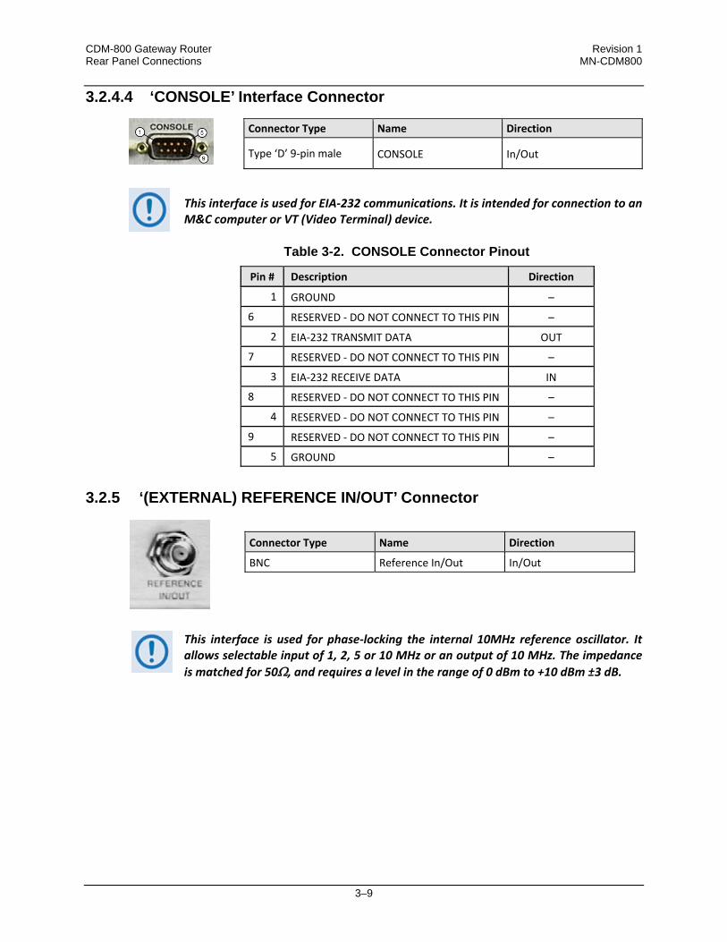
3.2.4.4 ‘CONSOLE’ Interface Connector
Connector Type Name Direction
Type ‘D’ 9‐pin male CONSOLE In/Out
This interface is used for EIA‐232 communications. It is intended for connection to an M&C computer or VT (Video Terminal) device.
Table 3-2. CONSOLE Connector Pinout
Pin # Description Direction
1 GROUND –
6 RESERVED ‐ DO NOT CONNECT TO THIS PIN –
2 EIA‐232 TRANSMIT DATA OUT
7 RESERVED ‐ DO NOT CONNECT TO THIS PIN –
3 EIA‐232 RECEIVE DATA IN
8 RESERVED ‐ DO NOT CONNECT TO THIS PIN –
4 RESERVED ‐ DO NOT CONNECT TO THIS PIN –
9 RESERVED ‐ DO NOT CONNECT TO THIS PIN –
5 GROUND –
3.2.5 ‘(EXTERNAL) REFERENCE IN/OUT’ Connector
This interface is used for phase‐locking the internal 10MHz reference oscillator. It allows selectable input of 1, 2, 5 or 10 MHz or an output of 10 MHz. The impedance is matched for 50Ω, and requires a level in the range of 0 dBm to +10 dBm ±3 dB.
Connector Type Name Direction
BNC Reference In/Out In/Out
CDM-800 Gateway Router Revision 1 Rear Panel Connections MN-CDM800
3–10
3.3 CDM-800 Ground and Power Connections
3.3.1 Chassis Ground Interface
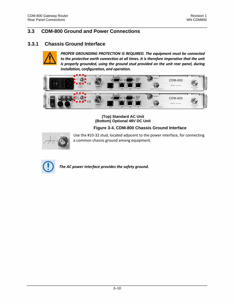
PROPER GROUNDING PROTECTION IS REQUIRED. The equipment must be connected to the protective earth connection at all times. It is therefore imperative that the unit is properly grounded, using the ground stud provided on the unit rear panel, during installation, configuration, and operation.
Figure 3-4. CDM-800 Chassis Ground Interface Use the #10‐32 stud, located adjacent to the power interface, for connecting
a common chassis ground among equipment.
The AC power interface provides the safety ground.
(Top) Standard AC Unit (Bottom) Optional 48V DC Unit

CDM-800 Gateway Router Revision 1 Rear Panel Connections MN-CDM800
3–11
3.3.2 115V/230V Alternating Current (AC) Power Interface (Standard)
Figure 3-5. CDM-800 AC Power Interface
3.3.2.1 AC Operation – Applying Power
Figure 3-6. Applying AC Power to the CDM-800 To apply AC power to the CDM‐800:
• First, plug the provided AC power cord female end into the unit.
• Then, plug the AC power cord male end into the user‐supplied power source.
• Finally, switch the unit ON.
Feature Description
1 On / Off Switch
2 Press‐fit Fuse Holder
3 IEC Three‐prong Connector
AC Power Specifications
Input Power 40W maximum, 20W typical
Input Voltage 100V to 240V AC, +6%/‐10%, autosensing (total absolute max. range is 90V to 254V AC)
Connector Type IEC
Fuse Protection
Line and neutral fusing(2X) 20mm Slow‐blow type fuses: T2.5A (2.5A) (115V or 230V AC operation without BUC) T4.5A (4.5A) (115V or 230V AC operation with BUC)
CDM-800 Gateway Router Revision 1 Rear Panel Connections MN-CDM800
3–12
3.3.2.2 AC Operation – Replacing Fuses
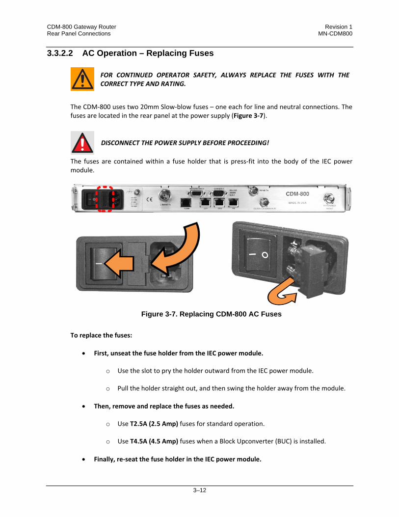
FOR CONTINUED OPERATOR SAFETY, ALWAYS REPLACE THE FUSES WITH THE CORRECT TYPE AND RATING.
The CDM‐800 uses two 20mm Slow‐blow fuses – one each for line and neutral connections. The fuses are located in the rear panel at the power supply (Figure 3‐7).
DISCONNECT THE POWER SUPPLY BEFORE PROCEEDING!
The fuses are contained within a fuse holder that is press‐fit into the body of the IEC power module.
Figure 3-7. Replacing CDM-800 AC Fuses To replace the fuses:
• First, unseat the fuse holder from the IEC power module.
o Use the slot to pry the holder outward from the IEC power module.
o Pull the holder straight out, and then swing the holder away from the module.
• Then, remove and replace the fuses as needed.
o Use T2.5A (2.5 Amp) fuses for standard operation.
o Use T4.5A (4.5 Amp) fuses when a Block Upconverter (BUC) is installed.
• Finally, re‐seat the fuse holder in the IEC power module.

CDM-800 Gateway Router Revision 1 Rear Panel Connections MN-CDM800
3–13
3.3.3 48V Direct Current (DC) Power Interface (Optional)
Figure 3-8. CDM-800 DC Power Interface
3.3.3.1 DC Operation – Applying Power
Figure 3-9. Applying DC Power to the CDM-800 To apply DC power to the CDM‐800:
• First, connect the user‐supplied (+) and (–) DC power leads to their respective terminals. Number 18 AWG minimum wires are recommended.
• Then, connect the user‐supplied DC power leads to the power source.
• Finally, switch the unit ON.
Feature Description
1 On / Off Switch
2 Screw‐in Fuse Holders / Receptacles
3 Power Terminal Block
DC Power Specifications
Input Power 25W (typical)245W (maximum with BUC)
Input Voltage 48V DC, nominal(36V to 60V)
Connector Type Terminal Block
Fuse Protection (2X) 20mm Slow‐blow type fuses:T3A (3.0A) Main T5A (5.0A) (BUC)

CDM-800 Gateway Router Revision 1 Rear Panel Connections MN-CDM800
3–14
3.3.3.2 DC Operation – Replacing Fuses
DISCONNECT THE POWER SUPPLY BEFORE PROCEEDING!
The fuses are contained within individual screw‐in receptacles located below the terminal blocks (Figure 3‐10).
Figure 3-10. Replacing CDM-800 DC Fuses To replace the fuses:
• First, unscrew either fuse holder from its receptacle. Then, remove and replace the
fuse:
o Use T3A (3 Amp) fuses for standard operation
o Use T5A (5 Amp) fuses when a Block Upconverter (BUC) is installed.
• Screw either fuse holder back into its receptacle.

4–1
Chapter 4. UPDATING FIRMWARE
4.1 Updating Firmware via the Internet
TO ENSURE OPTIMAL PERFORMANCE, IT IS IMPORTANT TO OPERATE THE CDM‐800 WITH ITS LATEST AVAILABLE FIRMWARE.
The CDM‐800 Gateway Router is factory‐shipped with its latest version of operating firmware. If a firmware update is needed, it can be acquired over satellite; by download from the Comtech EF Data Web site (www.comtechefdata.com); or from Comtech EF Data Customer Support during normal business hours via e‐mail or on CD by standard mail delivery. The CDM‐800 Firmware Update process is as follows:
• Perform the update without opening the CDM‐800 – over satellite or by connecting the rear panel ‘FE’ 10/100 Fast Ethernet port to the Ethernet port of a user‐supplied PC.
• Download the firmware update via the Internet to the user PC.
• Transfer the firmware update, via File Transfer Protocol (FTP), from the user PC to the CDM‐800.

CDM-800 Gateway Router Revision 1 Updating Firmware MN-CDM800
4–2
(Left) Standard CDM-800 115V/230V AC Unit(Right) Optional CDM-800 48V DC Unit
4.2 Getting Started: Preparing for the Firmware Download
1. First, identify the CDM‐800 assigned Management IP Address, and the firmware number/ revision letter/version number.
User‐supplied items needed:
• A Microsoft Windows‐based PC, equipped with available serial and Ethernet ports; a
compatible Web browser (e.g., Internet Explorer); and a terminal emulator program (e.g., Tera Term or HyperTerminal).
• A 9‐pin serial cable to connect the PC to the CDM‐800.
A. Use the 9‐pin serial cable to connect the CDM‐800 ‘CONSOLE’ port to a serial port on the user PC.
B. On the PC: Open the terminal emulator program.
Refer to your terminal emulator program HELP feature or user guide for operating and configuration instructions.
Configure the utility program serial port communication and terminal display operation:
• 38400 bps (Baud Rate) • 8 Data Bits • 1 Stop Bit
• Parity = NO • Port Flow Control = NONE • Display New line Rx/Tx: CR
• Local Echo = ON
C. On the CDM‐800: Turn on the power.
D. On the PC: Review and record the information displayed on the CDM‐800 Command Line Interface (CLI):
• Management IP Address (e.g., default is 192.168.1.10/24) • Firmware Number and Revision Letter (e.g., FW‐0000430J) • Firmware Release Version (e.g., 1.3.2)

CDM-800 Gateway Router Revision 1 Updating Firmware MN-CDM800
4–3
See Chapter 6. SERIAL‐BASED REMOTE PRODUCT MANAGEMENT for information and instructions on using the CDM‐800 Serial Command Line Interface.
E. Alternately, use the CDM‐800 Web Server Interface to obtain the firmware information.
• Use an Ethernet hub, switch, or direct
cable connection to connect the CDM‐800 ‘FE’ 10/100 Fast Ethernet port to the PC.
• On the PC: Use a Web browser (e.g., Internet Explorer) to log in to the CDM‐800 Web Server Interface and access the ‘Admin | Firmware’ page. Then, make note of the Slot #1 and Slot #2 firmware loads:
See Chapter 5. ETHERNET‐BASED REMOTE PRODUCT MANAGEMENT for information and instructions on using the CDM‐800 Web Server Interface.
2. Next, create a temporary folder (subdirectory) on the user PC for the firmware archive
download.
• Drive letter “c:” is used in these examples. Any valid, writable drive letter can be used.
• Typical for all tasks: Type the command without quotes, and then press Enter to execute.

CDM-800 Gateway Router Revision 1 Updating Firmware MN-CDM800
4–4
There are several ways the user may use create a temporary folder on a Windows‐based PC:
A. Use the Windows Desktop to create and rename the temporary folder.
• Right‐click anywhere on the desktop to open the popup submenu, and then select New > Folder to create the temporary folder. The new folder will be created on the desktop.
• Right‐click on the new folder and then select Rename from the popup submenu. Rename this folder to "temp" or some other convenient, unused name.
B. Use Windows Explorer to create and rename the temporary folder.
• Select File > New > Folder to create the temporary folder. The new folder will be created in the active folder.
• Right‐click the “New Folder” folder name, and then rename this folder to "temp" or
some other convenient, unused name.
C. Use the ‘Run’ and ‘Browse’ windows to create and rename the temporary folder.
• Select [Start] on the Windows taskbar, and then click the Run... icon. The ‘Run’ window will open.
• Click [Browse] in the ‘Run’ window. The ‘Browse’ window will open. • Click the ‘Create New Folder’ icon in the ‘Browse’ window. The new folder will be
created. • Right‐click the “New Folder” folder name, and then rename this folder to “temp” or
some other convenient, unused name.

CDM-800 Gateway Router Revision 1 Updating Firmware MN-CDM800
4–5
D. Use Windows Command‐line to create the temporary folder.
• First, click [Start] on the Windows taskbar, and then click the Run... icon (or, depending on Windows OS versions prior to Windows 95, click the MS‐DOS Prompt icon from the Main Menu).
• Next, open a Command‐line window…
o For Windows 95 or Windows 98 – Type “command”. o For any Windows OS versions later than Windows 98 – Type “cmd” or
“command”.
o Alternately, from [Start], select All Programs > Accessories > Command Prompt.
o Finally, from the Command‐line ‘c:\>’ prompt, type “mkdir temp” or “md temp”
(mkdir and md stand for make directory), and then click [OK].
There should now be a "temp" folder created and available for placement of the firmware file download.

CDM-800 Gateway Router Revision 1 Updating Firmware MN-CDM800
4–6
4.3 Downloading and Extracting the Firmware Update
1. First, download the firmware update archive file from the Comtech EF Data Web site:
A. Go online to www.comtechefdata.com.
B. On the Main page – under Support Information or the Support tab, select the Software Downloads hyperlink.
C. On the Software Downloads page – click Download Flash and Software Update Files.
D. On the Flash Updates Index page – select the (Select a Product Line) Advanced VSAT Series hyperlink.
E. On the Advanced VSAT Solutions product page – select the CDM‐800 product hyperlink.
F. Select the appropriate firmware archive EXE or ZIP file download hyperlink.
• About Firmware Numbers, File Versions, and Formats: The Comtech EF Data Web site catalogues its firmware update files by product type (e.g., router, modem, etc.), the specific model, and optional hardware configurations. The CDM‐800 firmware download hyperlink appears as F0000430X_V###, where ‘X’ denotes the revision letter, and ‘###’ represents the firmware version (e.g., V132 = Version 1.3.2).
• About File Archive Formats: Comtech EF Data provides its downloadable files in two compressed archive formats: *.exe (self‐extracting) and *.zip (compressed). The *.exe file does not require a file archiver and compression utility program such as PKZIP for Windows, WinZip, ZipCentral, etc. (PKZIP for DOS is not supported due to file naming conventions). Comtech EF Data does not provide this utility program. Some firewalls do not allow the download of *.exe files. Download the *.zip file instead, and extract the firmware files from the archive download with a user‐supplied utility program. For detailed information on handling archived files, refer to the utility program Help documentation.
G. Download the archive file to the temporary folder.
• Once the EXE or ZIP hyperlink is selected the ‘File Download’ window opens and
prompts selection of [Open] or [Save]:

CDM-800 Gateway Router Revision 1 Updating Firmware MN-CDM800
4–7
o Click [Open] to turn over file extraction to the user‐supplied utility program. Be sure to extract the firmware files to the “temp” folder created earlier.
o Click [Save] to open the ‘Save As’ window. Be sure to select and [Save] the archive *.exe or *.zip file to the “temp” folder created earlier.
o Otherwise, click [Cancel] to quit and exit the file download process.
2. Next, extract the firmware files from the archive file. • (If not already done with File Download > [Open]) Extract the firmware files from the
downloaded *.exe or *.zip archive file with the user‐supplied utility program: o Double‐click on the archive file name, and then follow the prompts provided by the
user‐supplied utility program. Extract, at a minimum, two files:
FW0000430x_CDM800.bin – the Firmware Bulk image file (where ‘x’ denotes the revision letter), and
CDM‐800ReleaseNotes_v#‐#‐#.pdf – the Firmware Release Notes PDF file
(where ‘#‐#‐#’ denotes the firmware version number). 3. Confirm availability of the firmware files in the temporary folder.
There are several ways the user may view the contents of the temporary folder on a Windows‐based PC:
A. From the Windows Desktop:
• Double‐left‐click the “temp” folder saved to the Windows Desktop.
• Use Windows Explorer to locate, and then double‐left‐click the “temp” folder.
• Use the ‘Browse’ window ([Start] > ...Run > [Browse]) to locate, and then double‐
click the “c:\temp” folder.
B. Using Command‐line:
• Type “cd c:\temp” at the Command‐line prompt to change to the temporary directory created earlier using Command‐line.
CDM-800 Gateway Router Revision 1 Updating Firmware MN-CDM800
4–8
• Type “dir” to list the files extracted to the temporary directory from the downloaded archive file.
The firmware files have been successfully downloaded and are now available for transfer to the CDM‐800.
4.4 Performing the Ethernet FTP Upload Procedure
To proceed with the firmware update procedure, assumptions are made that:
• The CDM‐800 is connected to a user‐supplied, Windows‐based PC, and:
o The PC serial port is connected to the CDM‐800 ‘CONSOLE’ port.
o The PC Ethernet port is connected to the CDM‐800 ‘FE’ 10/100 BaseT Fast Ethernet port with a user‐supplied hub, switch, or direct Ethernet cable connection.
o The PC is running a terminal emulation program (for operation of the CDM‐800 Serial Command Line Interface) and a compatible Web browser (for operation of the CDM‐800 Web Server Interface).
• The CDM‐800 Management IP Address has been noted using the CDM‐800 Serial Command Line Interface (CLI), and the firmware has been identified using either the CLI or the CDM‐800 Web Server Interface ‘Admin | Firmware’ page.
• The latest firmware files have been downloaded or otherwise received from Comtech EF Data and are available on the user PC in an accessible temporary folder.
1. Use Command‐line to send a “PING” command to confirm proper connection and communication between the user PC and the CDM‐800:
• If the Management IP Address of the unit is still not known, type “info” at the CLI
CDM‐800> command prompt and record the displayed information. Alternately, use Serial Remote Control or the Web Server Interface:
o Serial Remote Control – Type the “<0/IPA?” remote query (without quotes) at the
CLI CDM‐800> command prompt. The unit returns the configured Management IP Address:
>0000/IPA=192.168.1.10/24 (default)
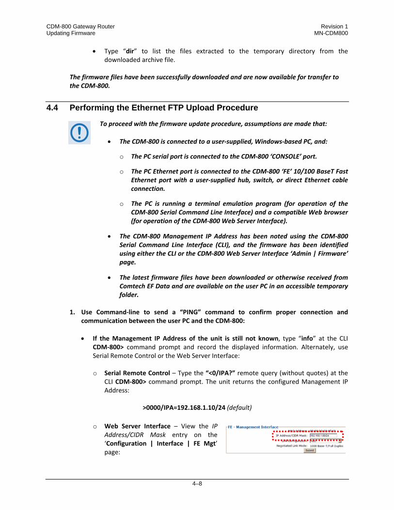
o Web Server Interface – View the IP
Address/CIDR Mask entry on the ‘Configuration | Interface | FE Mgt’ page:

CDM-800 Gateway Router Revision 1 Updating Firmware MN-CDM800
4–9
• Once the Management IP address is known – use Command‐line to PING: Type “ping xxx.xxx.xxx.xxx” at the Command‐line prompt (where ‘xxx.xxx.xxx.xxx’ is the unit Management IP Address).
The response should confirm whether or not the unit is properly connected and communicating.
2. Use Command‐line to transfer (FTP) the files from the user PC to the CDM‐800:
• Type "ftp xxx.xxx.xxx.xxx" (where ‘xxx.xxx.xxx.xxx’ denotes the Management IP
address of the unit being upgraded.
• Enter the username and password assigned to the unit. The default username and password is “comtech”.
• Type “bin” to set the binary transfer mode.
• Type "put FW‐0000430x_CDM800.bin" (where ‘x’ denotes the revision letter) at the
Command‐line prompt, without quotes, to begin the file transfer. The process sequences through several blocks – this may take several minutes for the transfer to occur. Once the upgrade file is received, the image is written to Flash memory and the unit transmits the message “UPLOAD COMPLETE.”
In the event you receive the “Connection closed by remote host.” message, wait another minute before continuing. The CDM‐800 update sometimes takes longer than the FTP client allows.
• Type "bye" to terminate the FTP session, and then close the Command‐line window.
3. Use the CLI or the Web Server Interface ‘Admin | Firmware’ page to verify that the PC‐to‐
Unit FTP file transfer was successful.
4. Use the CDM‐800 Web Server Interface to select the firmware and reboot the unit:
A. Select the desired Boot Slot (Image):
• Go to the Web Server Interface ‘Admin | Firmware’ page.
• Use the ‘Boot From:’ drop‐down menu to select Latest, Slot 1, or Slot 2 (in the Firmware Configuration section).
By default, the unit will boot from the Slot that stores the firmware version having the latest date (Boot From: Latest). ‘Boot From:’ may also be set to force the unit to boot up using either firmware image loaded in Slot 1 or Slot 2.
• Click [Submit] to save the setting.
CDM-800 Gateway Router Revision 1 Updating Firmware MN-CDM800
4–10
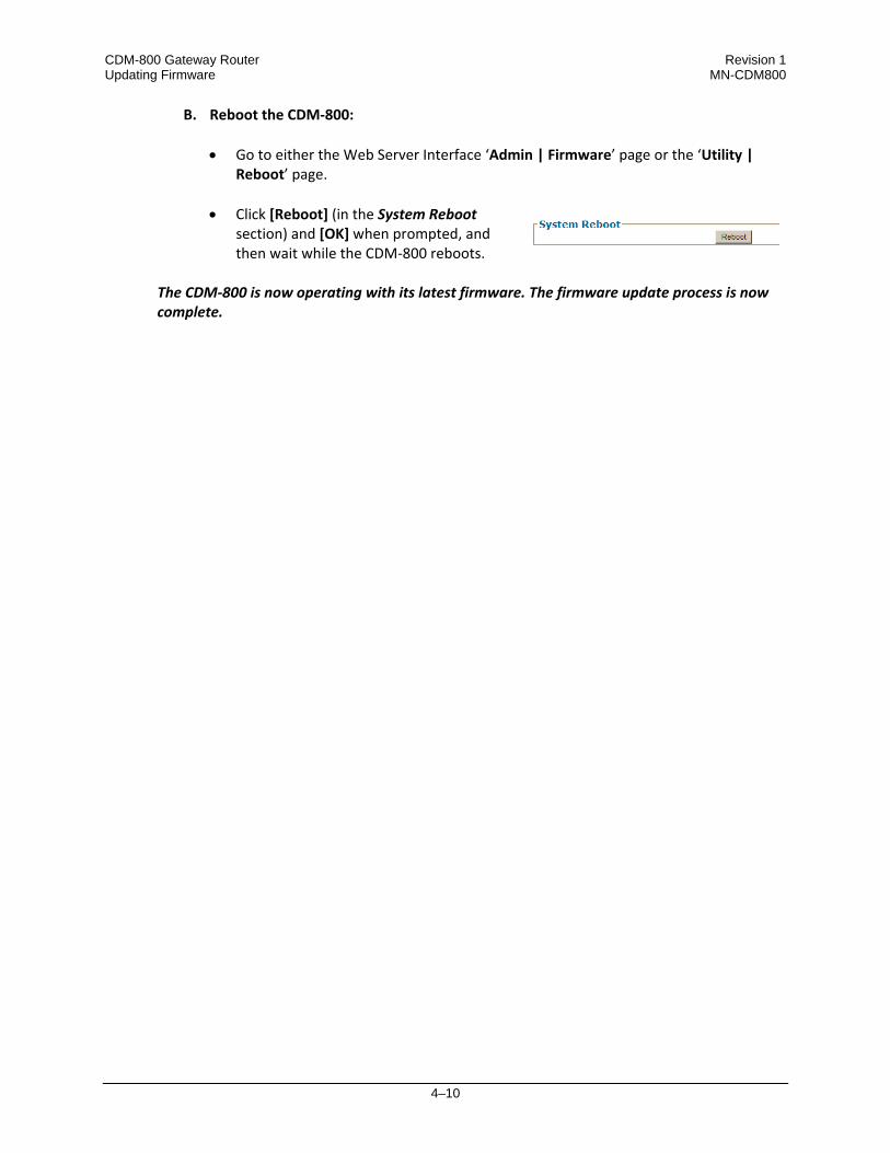
B. Reboot the CDM‐800:
• Go to either the Web Server Interface ‘Admin | Firmware’ page or the ‘Utility | Reboot’ page.
• Click [Reboot] (in the System Reboot
section) and [OK] when prompted, and then wait while the CDM‐800 reboots.
The CDM‐800 is now operating with its latest firmware. The firmware update process is now complete.

5–1
Chapter 5. ETHERNET-BASED REMOTE PRODUCT
MANAGEMENT
5.1 Introduction
Ethernet‐based Remote Product Management of the CDM‐800 Gateway Router is available using the rear panel ‘FE’ RJ‐45 10/100 BaseT Fast Ethernet M&C port.
1. TO PROCEED WITH ETHERNET‐BASED REMOTE PRODUCT MANAGEMENT (SNMP OR WEB SERVER), ASSUMPTIONS ARE MADE THAT:
• The CDM‐800 is operating with the latest version firmware files.
• The CDM‐800 is connected to a user‐supplied, Windows‐based PC as follows:
o The PC serial port is connected to the CDM‐800 rear panel ‘CONSOLE’
port with a user‐supplied serial cable.
o The PC Ethernet port is connected to the CDM‐800 rear panel ‘FE’ 10/100 BaseT Ethernet port with a user‐supplied hub, switch, or direct Ethernet cable connection.
o The user PC is running a terminal emulation program (for operation of
the CDM‐800 Serial Command Line Interface) and a compatible Web browser (for operation of the CDM‐800 Web Server Interface).
• The CDM‐800 Management IP Address has been noted using the CDM‐800
Serial Command Line Interface (CLI).
2. USE OF THE ETHERNET‐BASED SNMP INTERFACE IS RECOMMENDED ONLY FOR ADVANCED USERS. ALL OTHER USERS ARE STRONGLY ENCOURAGED TO USE THE CDM‐800 WEB SERVER INTERFACE FOR MONITOR AND CONTROL (M&C) OF THE CDM‐800.

CDM-800 Gateway Router Revision 1 Ethernet-based Remote Product Management MN-CDM800
5–2
5.2 Ethernet Management Interface Protocols
The user PC facilitates access to Ethernet‐based remote monitor and control (M&C) of the CDM‐800 through two separately‐operated protocols: • Simple Network Management Protocol (SNMP). This requires a user‐supplied Network
Management System (NMS) and a user‐supplied Management Information Base (MIB) File Browser.
• The CDM‐800 Web Server (HTTP) Interface. This requires a compatible user‐supplied Web browser such as Internet Explorer.
5.2.1 Ethernet Management Interface Access
Access to the CDM‐800 Ethernet Management Interface requires the user to specify the unit Management IP Address. Via use of a terminal emulator connected to the rear panel 9‐pin serial ‘CONSOLE’ port, this address may be obtained from the CDM‐800 Serial Interface upon power‐up of the unit. As shown, a number of operational parameters (including the unit factory‐default IP addresses) are displayed. The factory‐assigned default IP addresses are provided in the table that follows (if otherwise assigned, the user may use the last column to write down the IP Addresses for future reference):
Description Default Address User-assigned Address
‘FE’ Management IP Address 192.168.1.10 _____________________
‘GE1’ (GigE Traffic ) IP Address 10.10.1.10 _____________________
‘GE2’ (GigE Traffic ) IP Address 10.10.2.10 _____________________
See Chapter 6. SERIAL‐BASED REMOTE PRODUCT MANAGEMENT for details on setting up and using the CDM‐800 Serial Interface.
CDM-800 Gateway Router Revision 1 Ethernet-based Remote Product Management MN-CDM800
5–3
5.3 SNMP Interface
The Simple Network Management Protocol (SNMP) is an Internet‐standard protocol for managing devices on IP networks. An SNMP‐managed network consists of three key components:
• The managed device. This includes the CDM‐840 Remote Router.
• The SNMP Agent. The software that runs on the CDM‐840. The CDM‐840 SNMP Agent supports both SNMPv1 and SNMPv2c.
• The user‐supplied Network Management System (NMS). The software that runs on the manager.
5.3.1 Management Information Base (MIB) Files
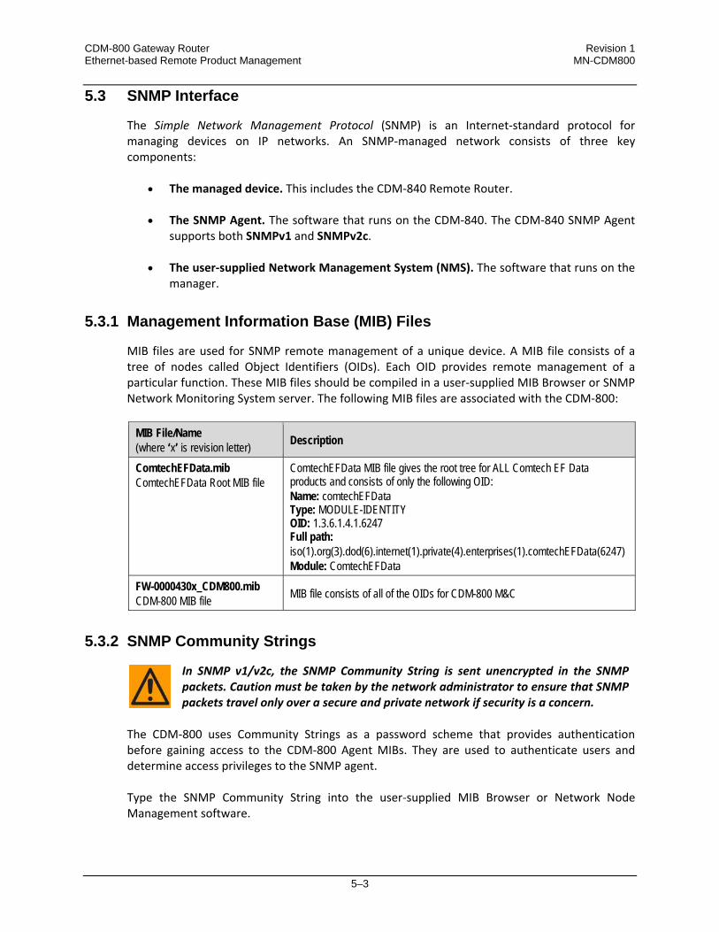
MIB files are used for SNMP remote management of a unique device. A MIB file consists of a tree of nodes called Object Identifiers (OIDs). Each OID provides remote management of a particular function. These MIB files should be compiled in a user‐supplied MIB Browser or SNMP Network Monitoring System server. The following MIB files are associated with the CDM‐800:
MIB File/Name (where ‘x’ is revision letter) Description
ComtechEFData.mib ComtechEFData Root MIB file
ComtechEFData MIB file gives the root tree for ALL Comtech EF Data products and consists of only the following OID: Name: comtechEFData Type: MODULE-IDENTITY OID: 1.3.6.1.4.1.6247 Full path: iso(1).org(3).dod(6).internet(1).private(4).enterprises(1).comtechEFData(6247) Module: ComtechEFData
FW-0000430x_CDM800.mib CDM-800 MIB file MIB file consists of all of the OIDs for CDM-800 M&C
5.3.2 SNMP Community Strings
In SNMP v1/v2c, the SNMP Community String is sent unencrypted in the SNMP packets. Caution must be taken by the network administrator to ensure that SNMP packets travel only over a secure and private network if security is a concern.
The CDM‐800 uses Community Strings as a password scheme that provides authentication before gaining access to the CDM‐800 Agent MIBs. They are used to authenticate users and determine access privileges to the SNMP agent. Type the SNMP Community String into the user‐supplied MIB Browser or Network Node Management software.

CDM-800 Gateway Router Revision 1 Ethernet-based Remote Product Management MN-CDM800
5–4
The user defines two Community Strings for SNMP access:
• Read Community default = public
• Write Community default = private
For proper SNMP operation, the CDM‐800 MIB files must be used with the associated version of the CDM‐800 router M&C. Refer to the CDM‐800 FW Release Notes for information on the required FW/SW compatibility.
5.4 Web Server (HTTP) Interface
A user‐supplied Web browser allows the full monitoring and control (M&C) of the CDM‐800 from its Web Server Interface. This embedded Web application is designed for, and works best with, Microsoft Internet Explorer Version 7.0 or higher.
5.4.1 User Login
Type the CDM‐800 Management IP Address (shown here as http://xxx.xxx.xxx.xxx) into the Address area of the user PC Web browser: The login page opens. Enter the assigned User Name and Password – the default for both is comtech. Click [Log On]. If the User Name and Password are accepted: The CDM‐800 Gateway Router Web Server Interface Home page, similar to the example shown here, appears:
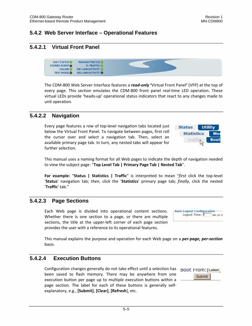
CDM-800 Gateway Router Revision 1 Ethernet-based Remote Product Management MN-CDM800
5–5
5.4.2 Web Server Interface – Operational Features
5.4.2.1 Virtual Front Panel
The CDM‐800 Web Server Interface features a read‐only ‘Virtual Front Panel’ (VFP) at the top of every page. This section emulates the CDM‐800 front panel real‐time LED operation. These virtual LEDs provide ‘heads‐up’ operational status indicators that react to any changes made to unit operation.
5.4.2.2 Navigation
Every page features a row of top‐level navigation tabs located just below the Virtual Front Panel. To navigate between pages, first roll the cursor over and select a navigation tab. Then, select an available primary page tab. In turn, any nested tabs will appear for further selection. This manual uses a naming format for all Web pages to indicate the depth of navigation needed to view the subject page: “Top Level Tab | Primary Page Tab | Nested Tab”. For example: “Status | Statistics | Traffic” is interpreted to mean “first click the top‐level ‘Status’ navigation tab; then, click the ‘Statistics’ primary page tab; finally, click the nested ‘Traffic’ tab.”
5.4.2.3 Page Sections
Each Web page is divided into operational content sections. Whether there is one section to a page, or there are multiple sections, the title at the upper‐left corner of each page section provides the user with a reference to its operational features. This manual explains the purpose and operation for each Web page on a per‐page, per‐section basis.
5.4.2.4 Execution Buttons
Configuration changes generally do not take effect until a selection has been saved to flash memory. There may be anywhere from one execution button per page up to multiple execution buttons within a page section. The label for each of these buttons is generally self‐explanatory, e.g., [Submit], [Clear], [Refresh], etc.

CDM-800 Gateway Router Revision 1 Ethernet-based Remote Product Management MN-CDM800
5–6
All execution buttons serve the same purpose – to save the configuration changes to flash memory, or to execute an update of the active page display.
Always make sure to click the execution button before selecting another Web page. Any changes made on that previous page will not be saved if the execution button for those functions Is not clicked.
5.4.2.5 Feature Selection
Drop‐down menus provide access to multiple setting selections, where available for a specific function. Move the cursor to the drop‐down tab, and then left‐click the tab. The drop‐down will open and list the available selections. Move the cursor to the desired choice and then left‐click once again to select that choice.
5.4.2.6 Text or Data Entry
Text boxes are provided any time an alphanumeric entry is required for unit access or configuration. Move the cursor to the text box, and then left‐click anywhere inside the box. Then, use the keyboard to type in the desired alphanumeric string. Press Enter when done.

CDM-800 Gateway Router Revision 1 Ethernet-based Remote Product Management MN-CDM800
5–7
5.4.3 Web Server Interface – Menu Tree
The tree diagram blocks that are marked with (*) denote pages that are functional only when that particular FAST feature has been purchased and activated. Blocks that are marked with (**) denote pages that are functional only when a VIPERSAT MANAGEMENT SYSTEM (VMS) is installed and is recognized as operational.
The CDM‐800 Web Server Interface features five (5) navigation tabs (shown in blue):
• Home • Admin • Configuration • Status • Utility Beyond this top‐level row of navigation tabs, primary page tabs (green) and nested page tabs (yellow) direct the user to further in‐depth M&C functionality.
Click any tab to continue.

CDM-800 Gateway Router Revision 1 Ethernet-based Remote Product Management MN-CDM800
5–8
5.4.4 Web Server Interface Page Descriptions
Access to and availability of certain CDM-800 Web Server Interface pages is dependent upon the FAST options purchased for operation as well as the detected presence of auxiliary products (e.g., VIPERSAT Management System, Redundancy Switches, etc.) installed and configured for use with the CDM-800. Such operational restrictions will be noted in the subsections that follow through the end of this chapter.
5.4.4.1 Home Pages
Click the Home or Contact tab to continue.
5.4.4.1.1 Home | Home
Use this page to identify the product and its current operating firmware version. From any location within the Web Server Interface, click the Home top‐level navigation tab and/or the nested page tab to view this informational page.
Figure 5‐1. Home | Home page

CDM-800 Gateway Router Revision 1 Ethernet-based Remote Product Management MN-CDM800
5–9
5.4.4.1.2 Home | Contact
Use this page to reference basic contact information needed to reach Comtech EF Data Sales and Customer Support via phone, fax, or Web/e‐mail hyperlinks.
Figure 5‐2. Home | Contact page
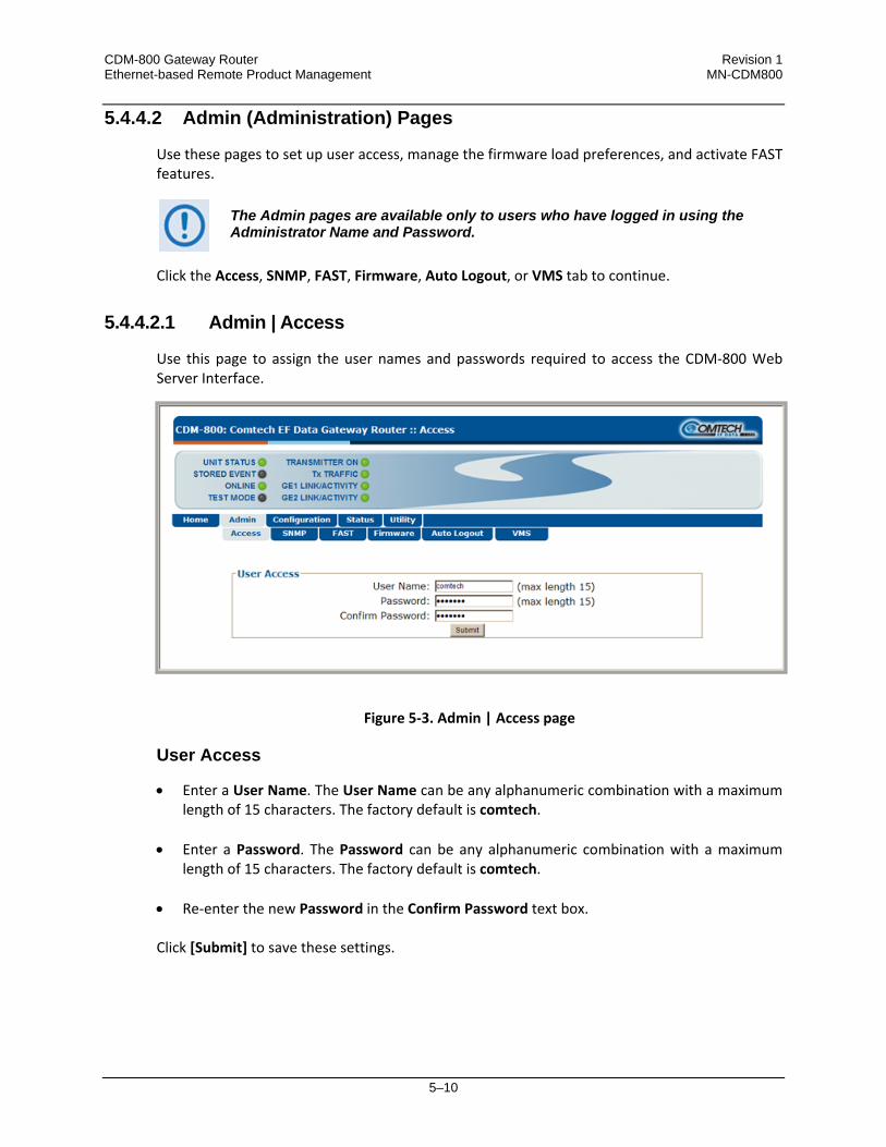
CDM-800 Gateway Router Revision 1 Ethernet-based Remote Product Management MN-CDM800
5–10
5.4.4.2 Admin (Administration) Pages
Use these pages to set up user access, manage the firmware load preferences, and activate FAST features.
The Admin pages are available only to users who have logged in using the Administrator Name and Password.
Click the Access, SNMP, FAST, Firmware, Auto Logout, or VMS tab to continue.
5.4.4.2.1 Admin | Access
Use this page to assign the user names and passwords required to access the CDM‐800 Web Server Interface.
Figure 5‐3. Admin | Access page
User Access
• Enter a User Name. The User Name can be any alphanumeric combination with a maximum length of 15 characters. The factory default is comtech.
• Enter a Password. The Password can be any alphanumeric combination with a maximum length of 15 characters. The factory default is comtech.
• Re‐enter the new Password in the Confirm Password text box. Click [Submit] to save these settings.

CDM-800 Gateway Router Revision 1 Ethernet-based Remote Product Management MN-CDM800
5–11
5.4.4.2.2 Admin | SNMP
Sect. 5.3 SNMP Interface
Use this page to set up and return administration information for the CDM‐800 Simple Network Management Protocol (SNMP) feature.
Figure 5‐4. Admin | SNMP page
SNMP Configuration
THE SNMP TRAP DESTINATION IP ADDRESS FEATURE IS A FUTURE OFFERING. IT IS NON‐FUNCTIONAL AT THIS TIME.
• Enter an SNMP Read Community string. The SNMP Read Community string can be any
combination of characters and a length of 4 to 15 characters. The factory default SNMP Read Community string is public. Click [Submit] to save.
• Enter an SNMP Write Community string. The SNMP Write Community string can be any
combination of characters and a length of 4 to 15 characters. The factory default SNMP Write Community string is private.
Click [Submit] to save.

CDM-800 Gateway Router Revision 1 Ethernet-based Remote Product Management MN-CDM800
5–12
5.4.4.2.3 Admin | FAST
Appendix A. FAST
The CDM‐800 has a number of optional features that may be activated after purchase of the unit. Fully Accessible System Topology (FAST) Access Codes are unique authorization codes that may be purchased from Comtech EF Data during normal business hours, and then loaded into the unit using this page.
Figure 5‐5. Admin | FAST page
FAST Configuration
This read‐only section displays the available CDM‐800 FAST Features and the operational status for each option:
• The Option column lists each available FAST Feature.
• The Status column identifies each FAST Feature operational parameter(s). If an option is not
enabled, the column displays this information.

CDM-800 Gateway Router Revision 1 Ethernet-based Remote Product Management MN-CDM800
5–13
The complete roster of FAST Accessible Options is as follows:
Option Compression Hardware Payload Compression Card (CEFD KIT P/N KT-0000249) Tx Symbol Rate (VCM) Up to maximum 62 Msps Tx Header Compression Enabled Tx Payload Compression Enabled QoS (Quality of Service) Group QoS G.703 Clock Extension Enabled/Disabled Tx Frequency IF (50-180 MHz) and L-Band (950-2150 MHz)
FAST Upgrade
Serial Number (read‐only) – The serial number of the unit is required by Comtech EF Data when ordering FAST option upgrades. Take note of this number before contacting Comtech EF Data to order a CDM‐800 FAST option upgrade. FAST Code – Once a FAST upgrade order is placed and confirmed, the Comtech EF Data sales representative will provide a 20‐digit FAST Access Code. To perform the CDM‐800 FAST option upgrade:
Step Task
1 Use the FAST Configuration table to view the currently installed features.
2 Write down the unit Serial Number provided in the FAST Upgrade section:
Serial Number: __________________________
3 Contact a Comtech EF Data sales representative during normal business hours: • Provide the unit Serial Number to the representative.
• Identify and purchase the desired FAST option(s).
• Obtain the invoice, the 20‐digit FAST Access Code, and the FAST option activation
instructions.
4 Carefully enter the FAST Access Code into the FAST Code register text box.
5 Click [Submit] to finish.
6 Refer to the FAST Configuration table. The unit either accepts or rejects the code, and the FAST Configuration table refreshes to reflect any upgrades in operation.

CDM-800 Gateway Router Revision 1 Ethernet-based Remote Product Management MN-CDM800
5–14
5.4.4.2.4 Admin | Firmware
Chapter 4. UPDATING FIRMWARE
Use this page to select which image (boot Slot #) is to be designated as the active running firmware image – i.e., the version loaded for operation upon power‐up or soft reboot.
Figure 5‐6. Admin | Firmware page
Slot Information
This read‐only status section displays operating status for the firmware versions loaded into Slot #1 and Slot #2.
Firmware Configuration
Use the Boot From: drop‐down menu to select Latest, Slot 1, or Slot 2. The default selection is Latest, in which the unit will automatically select the image that contains the most current firmware. Click [Submit] when done. Note that the Slot Information section, which in Figure 5‐6 displays Slot #1 as the designated active running firmware image, will not update until after the unit is rebooted.
System Reboot
Click [Reboot] to reboot the CDM‐800. Once the unit reboots, the user must log in once again to resume use of the Web Server Interface. See the ‘Utility | Reboot’ page (Sect. 5.4.4.5.2) for full details about the reboot process.

CDM-800 Gateway Router Revision 1 Ethernet-based Remote Product Management MN-CDM800
5–15
5.4.4.2.5 Admin | Auto Logout
Use this page to incorporate the Auto Logout security measure.
Figure 5‐7. Admin | Auto Logout page
Auto Logout Configuration
Set an automatic logout time to safeguard access to an already logged‐in unit: • Enter a value from 1 to 15 minutes into the Logout Time box to configure this feature.
• Enter a value of 0 to disable this feature. Click [Submit] to save the desired configuration. When Auto Logout is configured, the active session terminates if the unit remains idle (i.e., when no user activity occurs) beyond the assigned Logout Time. A valid user name and password is then required to resume the CDM‐840 Web Server Interface session.

CDM-800 Gateway Router Revision 1 Ethernet-based Remote Product Management MN-CDM800
5–16
5.4.4.2.6 Admin | VMS
The VMS page is operational only when the optional VIPERSAT MANAGEMENT SYSTEM (VMS) is installed and operational.
VMS v3.x.x VIPERSAT Management System User Guide (CEFD P/N MN/22156)
Figure 5‐8. Admin | VMS page
Vipersat Management System Configuration
The acceptable/valid operating ranges for items in this section are provided in parentheses. • Network ID (1‐255) –The Network ID designation defines to which network the Gateway
Router belongs. All devices in a common network will have the same network ID. The network ID is used by the VMS to identify Vipersat units within a network and allows the VMS to manage multiple networks, each with its own unique network ID number.
• Management Base Port – The Management Base Port sets the starting IP port addressing for all VMS messages.
Use this setting ONLY if network port addressing is in contention. Changes to this address base affect the entire network, requiring configuration changes to all modems. Leave this setting at default (hex) C000 (des) 49152 to avoid unnecessary configuration changes.

CDM-800 Gateway Router Revision 1 Ethernet-based Remote Product Management MN-CDM800
5–17
• Management Multicast IP Port – The Multicast Address is the NMS Multicast IP address
assigned to all Gateway Routers in the Vipersat network that are managed by the VMS. This address must match the VMS Transmit Multicast Address.
Typical for each item, click [Submit] to save the setting change.
Vipersat Management System Status
This read‐only section provides available information on the VMS IP Address, Registration Status, and Version.

CDM-800 Gateway Router Revision 1 Ethernet-based Remote Product Management MN-CDM800
5–18
5.4.4.3 Configuration Pages
Use the nested ‘Configuration’ pages to configure all unit parameters. Click the Interface, Mod, ARP, Routing, Compression, or WAN tab to continue.
5.4.4.3.1 Configuration | Interface
Click the FE Mgt, GE‐1, or GE‐2 tab to continue.
5.4.4.3.1.1 Configuration | Interface | FE Mgt
Use this page to configure the rear panel ‘FE’ 10/100 BaseT Fast Ethernet M&C port.
Figure 5‐9. Configuration | Interface | FE Mgt Page
FE – Management Interface
The acceptable/valid operating ranges for items in this section are provided in parentheses. • MAC Address (read‐only) – The MAC Address cannot be changed.
• IP Address / CIDR Mask (8‐30) – Use this box to enter the IP Address and CIDR (Classless
Inter‐Domain Routing) Subnet Mask. • Link Configuration – Use the drop‐down menu to select the line speed and duplex setting
for the CDM‐800 FE interface. The available selections are: o Auto* o 100 BaseT / Full Duplex o 10 BaseT / Full Duplex o 100 BaseT / Half Duplex o 10 BaseT / Half Duplex

CDM-800 Gateway Router Revision 1 Ethernet-based Remote Product Management MN-CDM800
5–19
* Auto is the recommended configuration selection.
• Negotiated Link Mode (read‐only) – The actual negotiated line speed and duplex setting for
the FE Interface is displayed here. The viewable settings are:
o 10 BaseT / Full Duplex o 100 BaseT / Full Duplex o 10 BaseT / Half Duplex o 100 BaseT / Half Duplex
Set the desired configurations on this page. Click [Submit] to save.
5.4.4.3.1.2 Configuration | Interface | GE-1 or GE-2
The ‘Configuration | Interface | GE‐1’ and ‘GE‐2’ pages permit the user to configure the rear panel ‘GE1’ or ‘GE2’ 10/100/1000 BaseT Gigabit Ethernet ports.
Figure 5‐10. Configuration | Interface | GE‐1 or GE‐2 Page
GE-1 Interface or GE-2 Interface
The information and configuration options provided on these pages are identical to those featured on the ‘Configuration | Interface | FE Mgt’ page. See Sect. 5.4.4.3.1.1 for information about using these features.

CDM-800 Gateway Router Revision 1 Ethernet-based Remote Product Management MN-CDM800
5–20
5.4.4.3.2 Configuration | Mod (Modulator)
The upper range of Symbol Rate selection requires activation of the ‘TRANSMIT SYMBOL RATE’ FAST option.
Use this page to configure CDM‐800 Tx modulator operations.
Figure 5‐11. Configuration | Mod page
Modulator
The acceptable/valid operating range for each item in this section is provided in parentheses. • MODCOD / Data Rate (read‐only) – This section displays the effective data rate of the
default MODCOD based on the symbol rate.
• Symbol Rate – The range varies based on the MODCOD selected on the Group QoS configuration (see Sect. 5.4.4.3.5.1):
o 1000 to 62000 for MODCODs QPSK 1/4 through 8PSK 9/10. o 1000 to 47000 for MODCODs QPSK 1/4 through 16APSK 9/10. o 1000 to 37000 for MODCODs QPAK 1/4 through 32APSK 9/10.
Enter the Tx Symbol Rate in ksps, and then click [Submit] to save.

CDM-800 Gateway Router Revision 1 Ethernet-based Remote Product Management MN-CDM800
5–21
• FEC Type – At present, DVB‐S2 is the sole available FEC type.
• Tx Frequency (950 to 2150 MHz for L‐Band, 50 to 180 MHz for IF) – Enter the Tx frequency
in MHz.
• Frame – Use the drop‐down menu to select the Frame type as Normal or Short. This field will be forced to Normal if any MODCOD enabled in Group QoS (see Sect. 5.4.4.3.5.1) has a code rate of 9/10.
• Pilots (read‐only) – This feature is always ON. • Gold Code (000000 to 262141) – The Gold‐n Index indicates the Physical Layer spreading
sequence number. The default setting is all 0s.
• Roll Off – The Tx Alpha Rolloff (α) dictates how fast the spectral edges of the carrier are attenuated beyond the 3 dB bandwidth. With 20% rolloff the edge falls off more quickly than with 25% and 35%. Use the drop‐down menu to set the expected filter Tx Alpha Rolloff (α) of the carrier as 20%, 25%, or 35%. The default selection is 20%.
• Spectrum Invert – Use the drop‐down menu to select the Tx Spectrum Invert as Normal or Tx Spectrum Inverted.
• Power Level (‐40 to ‐5 dBm for L‐Band, ‐25 to ‐5.0 for 70/140 MHz) – Enter the Tx power level, in dBm.
• Carrier State – Use the drop‐down menu to select the Tx Carrier State as either Off or On. Select or enter the desired Tx Frequency, Tx Symbol Rate, Frame, Gold Code, Roll Off, Spectrum Invert, and Carrier State settings. Click [Submit] to save.
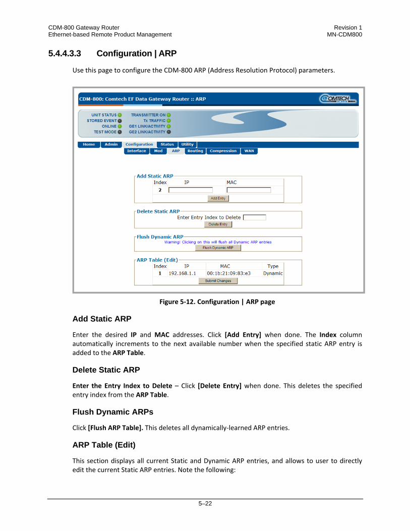
CDM-800 Gateway Router Revision 1 Ethernet-based Remote Product Management MN-CDM800
5–22
5.4.4.3.3 Configuration | ARP
Use this page to configure the CDM‐800 ARP (Address Resolution Protocol) parameters.
Figure 5‐12. Configuration | ARP page
Add Static ARP
Enter the desired IP and MAC addresses. Click [Add Entry] when done. The Index column automatically increments to the next available number when the specified static ARP entry is added to the ARP Table.
Delete Static ARP
Enter the Entry Index to Delete – Click [Delete Entry] when done. This deletes the specified entry index from the ARP Table.
Flush Dynamic ARPs
Click [Flush ARP Table]. This deletes all dynamically‐learned ARP entries.
ARP Table (Edit)
This section displays all current Static and Dynamic ARP entries, and allows to user to directly edit the current Static ARP entries. Note the following:

CDM-800 Gateway Router Revision 1 Ethernet-based Remote Product Management MN-CDM800
5–23
• Index (read‐only) – This is the internal table index and it cannot be edited.
• IP – Entry IP Address, format XXX.XXX.XXX.XXX. • MAC – Entry MAC Address, format YY:YY:YY:YY:YY. • Type (read‐only) – The entry Type is identifiable as Static or Dynamic and cannot be edited. Make the desired IP and MAC Address edits. Click [Submit Changes] to save.
5.4.4.3.4 Configuration | Routing | Routes
Use this page to enter static routes for IP traffic over the satellite or to another device on the LAN.
Figure 5‐13. Configuration | Routing | Routes page
Add New Route
Use this section to directly add a Route Table entry: • Index (read‐only) – This is the internal table index that is automatically assigned and cannot
be edited.

CDM-800 Gateway Router Revision 1 Ethernet-based Remote Product Management MN-CDM800
5–24
• Description – Enter a label string in this text box. This label helps to maintain the network. The assigned name must be unique and cannot contain any whitespace.
• Dest. IP/Mask – Enter a Destination IP Address/Mask in the form XXX.XXX.XXX.XXX/YY.
Multicast addresses must have a subnet of 32.
• Interf. – Use the drop‐down menu to select the Interface as toWAN or toLAN. • Next Hop IP – Enter the desired Next Hop IP Address for toLAN routes. Note that no Next
Hop entry is needed for toWAN routes.
• WAN Label – This label allows traffic to a defined remote designation to be passed. The valid label range is from 1 to 2047.
• If the WAN Label does not match any of the WAN Labels defined in the
CDM‐840 Remote Router, and then the packets will be dropped by the CDM‐840.
• The label will be forced to 0 for Multicast addresses. A unique WAN Label for each remote CDM‐840 is required for correct network operation. If the remote units have the same WAN Label, then multiple CDM‐840s will receive the same packet This can cause duplicate packets in the network as well as unnecessary packet processing, which can reduce the available processing resources for packets actually destined to a given remote CDM‐840.
• Header Comp. – Use the drop‐down menu to Disable or Enable operations for packets that
match on this route.
• Payload Comp. – Use the drop‐down menu to Disable or Enable operations for packets that match on this route.
Enter the desired information. Click [Add Entry] when done. The index automatically increments to the next available number when the new route is added.
Delete Route
Enter the Route Index to Delete. Click [Delete Entry] when done. This deletes the specified route entry from the route table.
Route Table (Edit)
Use the text boxes and drop‐down menus to edit all current Route Table entries, as described previously for the Add New Route section. Click [Submit Changes] to save these settings.

CDM-800 Gateway Router Revision 1 Ethernet-based Remote Product Management MN-CDM800
5–25
5.4.4.3.5 Configuration | Compression
Use the ‘Configuration | Routing | Routes’ page (Sect. 5.4.4.3.4) to enable or disable Header and Payload Compression operation.
Use this page to configure the optional Payload and Header Compression FAST feature, if installed.
Figure 5‐14. Configuration | Compression page
Refresh Rates
• Header Compression for UDP – Enter the User Datagram Protocol refresh rate, from 1 to 600 packets, or 1 second (whichever comes first).
• Header Compression for RTP – Enter the Real Time Protocol refresh rate, from 1 to 600 packets, or 1 second (whichever comes first).
• Header Compression for all others – Enter the default protocol refresh rate, from 1 to 600
packets, or 1 second (whichever comes first). • Payload Compression – Enter the Payload Compression refresh rate, from 1 to 600 packets,
or 1 second (whichever comes first). Set the desired Compression configurations. Click [Submit] to save.

CDM-800 Gateway Router Revision 1 Ethernet-based Remote Product Management MN-CDM800
5–26
5.4.4.3.5.1 Configuration | WAN | QoS
The appearance of this page changes depending on the selected QoS Control Mode.
(Top) Page with QoS Control Mode = OFF (Bottom) Page with QoS Control Mode = DiffServ (Banner, VFP, Menu Bar not shown)
Figure 5‐15. Configuration | WAN | QoS page

CDM-800 Gateway Router Revision 1 Ethernet-based Remote Product Management MN-CDM800
5–27
(Top) Page with QoS Control Mode = Max/Pri(ority) (Bottom) Page with QoS Control Mode = Min/Max (Banner, VFP, Menu Bar not shown)
Figure 5‐16. Configuration | WAN | QoS page (continued)

CDM-800 Gateway Router Revision 1 Ethernet-based Remote Product Management MN-CDM800
5–28
The following page sections are typical for all active QoS configurations.
Add / Change / Delete Group
Use the controls provided at the top and far right of this section to create / add new QoS configuration groups. The remainder of this section displays previously created groups, numbered in the order of creation. The individual columns are defined as follows: • Index – The automatically‐assigned internal index number for the group is identified here.
• Name – This is the name assigned to the group. It must be unique across all groups.
• CIR (kbps) – This is the Committed Information Rate for the QoS Group. The QoS Manager
will try to guarantee this date rate for all traffic that matches this group.
• MIR (kbps) – This is the Maximum Information Rate for the QoS Group. The QoS Manager will not allow traffic that matches this Group to send more than this data rate.
• Max MODCOD –This is the modulation code assigned to the group. There can be a maximum of six different MODCODs enabled at the same time. At the least, all traffic that matches this group is sent on this MODCOD. At best, the QoS Scheduler opportunistically puts these packets into a lower MODCOD in order to optimize utilization of the WAN bandwidth.
• Mode – When adding a new group or modifying an existing group, use the drop‐down menu
to select QoS operation as Off, DiffServ (Differentiated Services), Max/Pri (Maximum/ Priority), or Min/Max (Minimum/Maximum).
Note the following:
o Off – This mode disables QoS. Instead of an operable page, the ‘Configuration | WAN |
QoS’ page appears as shown in the top example in Figure 5‐15.
o DiffServ –This mode allows the CDM‐800 to operate in Differentiated Services (DiffServ) Mode to make it fully compliant to the Differentiated Services QoS RFC (Request For

CDM-800 Gateway Router Revision 1 Ethernet-based Remote Product Management MN-CDM800
5–29
Comments) standards. The ‘Configuration | WAN | QoS’ page appears as shown in the bottom example in Figure 5‐15.
o Max/Pri(ority) – This mode provides multi‐level traffic prioritization with the ability to
limit maximum traffic per priority class. The ‘Configuration | WAN | QoS’ page appears as shown in the top example in Figure 5‐16.
o Min/Max – This mode provides a Committed Information Rate (CIR) to each user‐
defined class of traffic with the ability to allow a higher burstable rate depending on availability. The ‘Configuration | WAN | QoS’ page appears as shown in bottom example in Figure 5‐16.
• To add a new group: Enter and select the desired settings, and then click [Add].
• To change (modify) an existing group: Select the index (group) row to edit. Once all
changes have been made, click [Change].
• To delete an existing group: Enter the index (group) to delete, and then click [Delete].
Group Table
This table displays the active configured QoS configuration groups. When more than one group is available, click Select to make that group the active operational configuration. Otherwise, if only a single group is created, operation defaults to that group.
Add / Delete Per Group Attribute
When more than one group is created, use the controls in this section to configure an attribute. When available, click Subnet to configure a subnet assigned to the group. All traffic within the configured subnet will be routed through this QoS Group. • To add a new group subnet: Enter the subnet in xxx.xxx.xxx.xxx/yy format, and then click
[Add].
• To delete an existing group attribute: Enter the index (group) to delete, and then click [Delete].
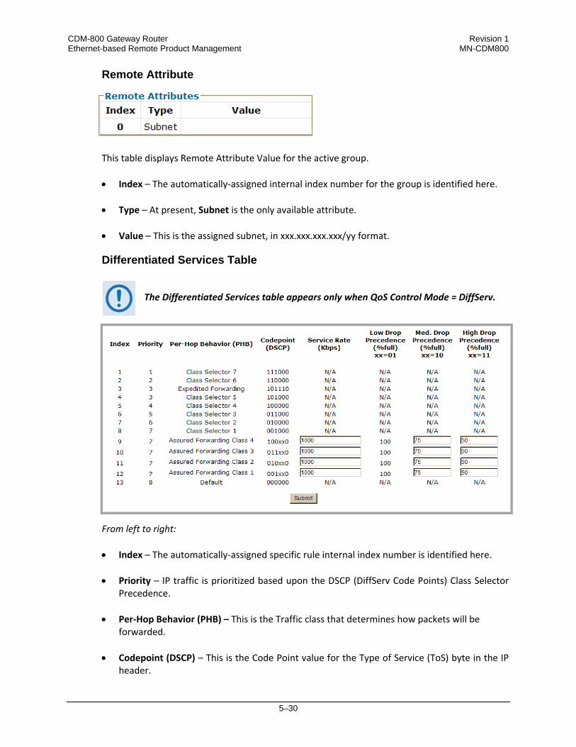
CDM-800 Gateway Router Revision 1 Ethernet-based Remote Product Management MN-CDM800
5–30
Remote Attribute
This table displays Remote Attribute Value for the active group. • Index – The automatically‐assigned internal index number for the group is identified here.
• Type – At present, Subnet is the only available attribute.
• Value – This is the assigned subnet, in xxx.xxx.xxx.xxx/yy format.
Differentiated Services Table
The Differentiated Services table appears only when QoS Control Mode = DiffServ.
From left to right: • Index – The automatically‐assigned specific rule internal index number is identified here.
• Priority – IP traffic is prioritized based upon the DSCP (DiffServ Code Points) Class Selector
Precedence.
• Per‐Hop Behavior (PHB) – This is the Traffic class that determines how packets will be forwarded.
• Codepoint (DSCP) – This is the Code Point value for the Type of Service (ToS) byte in the IP
header.

CDM-800 Gateway Router Revision 1 Ethernet-based Remote Product Management MN-CDM800
5–31
The option is provided to configure each queue to one of the following attributes. The acceptable/valid operating ranges are provided in this section in parentheses, where applicable. • Service Rate (Kbps) (0.000 / (Tx Data Rate)) – The minimum bandwidth will be served first
among the Assured Forwarding (ASFD) classes in case of bandwidth availability once Class Selector 7 through Class Selected 1 have been serviced.
• Drop Precedence – ASFD Class 4 through 1 Code Points (b100xx0, b011xx0, b010xx0, and b001xx0) carry the drop precedence value (xx). In case of network congestion, a Weighted Random Early Detection (WRED) congestion avoidance algorithm is imposed on these queues to drop the packets randomly rather than ‘tail drop.’
• Low Drop Precedence (% full) (0 to 100) – In case of congestion, the WRED is applied after
the queue depth exceeds the configured percentage value assigned for the Drop Precedence value b001.
• Med. Drop Precedence (% full) (0 to 99) – In case of congestion, the WRED is applied after
the queue depth exceeds the configured percentage value assigned for the Drop Precedence value b010.
• High Drop Precedence (% full) (0 to 99) – In case of congestion, the WRED is applied after
the queue depth exceeds the configured percentage value assigned for the Drop Precedence value b011.
Set the desired configurations in this section. Click [Submit] to save. The QoS Rules Per Group Table (Edit) and Add/Delete Per Group QoS Rule sections
appears only when QoS Control Mode = Max/Pri(ority) or Min/Max.

CDM-800 Gateway Router Revision 1 Ethernet-based Remote Product Management MN-CDM800
5–32
QoS Rules Per Group Table (Edit)
This read‐only section displays all existing QoS Rules Per Group Table entries. For the ‘Max/Pri(ority)’ page: For the ‘Min/Max’ page: From left to right: • Index – The automatically‐assigned specific rule internal index number is identified here.
• Protocol – The protocol for the specific rule is identified here. • Src IP/Mask – The Source IP Address/Mask is displayed here in the form
XXX.XXX.XXX.XXX/YY. • Dest IP/Mask – The Destination IP Address/Mask is displayed here in the form
XXX.XXX.XXX.XXX/YY. • Min Src Port / Max Src Port / Min Dst Port / Max Dst Port – The Source/Destination Ports
are displayed in these columns. • Min BW (Kbps) (‘Min/Max’ page only) / Max BW (Kbps) – The bandwidth values are
displayed in these columns. • Priority (‘Max/Pri(ority)’ page only) – The priority established for the specific rule is
identified here. • WRED – The WRED (Weighted Random Early Detection) setting for the specific rule is
identified here as Disable or Enable.
When WRED is enabled, the QoS Queue will attempt to smoothly drop packets as the queue gets congested. This is recommended for queues that will carry TCP packets.
• Filter All – The flow filter setting for the specific rule is identified here as Disable or Enable.
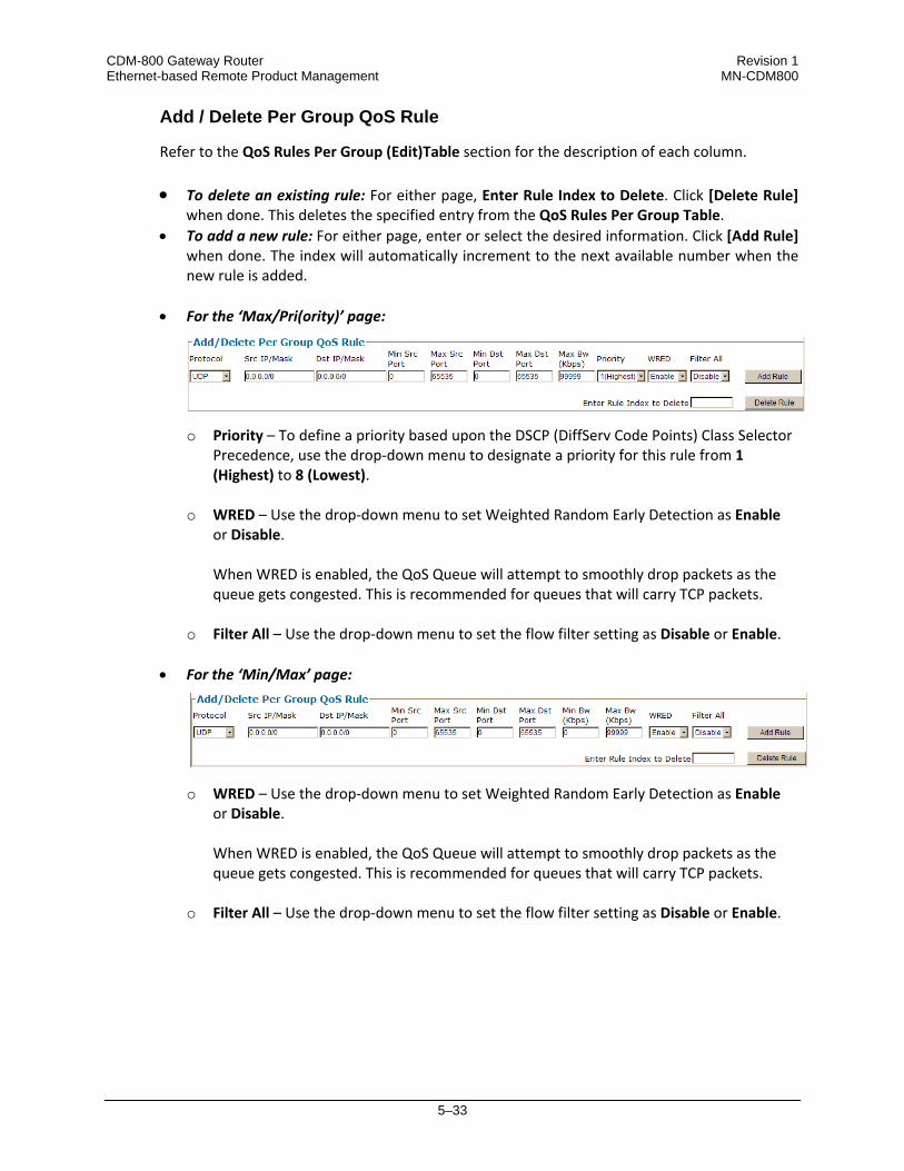
CDM-800 Gateway Router Revision 1 Ethernet-based Remote Product Management MN-CDM800
5–33
Add / Delete Per Group QoS Rule
Refer to the QoS Rules Per Group (Edit)Table section for the description of each column.
• To delete an existing rule: For either page, Enter Rule Index to Delete. Click [Delete Rule] when done. This deletes the specified entry from the QoS Rules Per Group Table.
• To add a new rule: For either page, enter or select the desired information. Click [Add Rule] when done. The index will automatically increment to the next available number when the new rule is added.
• For the ‘Max/Pri(ority)’ page:
o Priority – To define a priority based upon the DSCP (DiffServ Code Points) Class Selector Precedence, use the drop‐down menu to designate a priority for this rule from 1 (Highest) to 8 (Lowest).
o WRED – Use the drop‐down menu to set Weighted Random Early Detection as Enable or Disable.
When WRED is enabled, the QoS Queue will attempt to smoothly drop packets as the queue gets congested. This is recommended for queues that will carry TCP packets.
o Filter All – Use the drop‐down menu to set the flow filter setting as Disable or Enable.
• For the ‘Min/Max’ page:
o WRED – Use the drop‐down menu to set Weighted Random Early Detection as Enable or Disable. When WRED is enabled, the QoS Queue will attempt to smoothly drop packets as the queue gets congested. This is recommended for queues that will carry TCP packets.
o Filter All – Use the drop‐down menu to set the flow filter setting as Disable or Enable.

CDM-800 Gateway Router Revision 1 Ethernet-based Remote Product Management MN-CDM800
5–34
5.4.4.4 Status Pages
The Status pages provide status, event logging, and operational statistics windows. Click the Statistics or Monitor tab to continue.
5.4.4.4.1 Status | Statistics Pages
Click the Traffic, Router, Compression, or QoS tab to continue.
5.4.4.4.1.1 Status | Statistics | Traffic
Use this page to view read‐only, abridged status windows pertaining to the basic operational statistics for the Ethernet, Modulator, and Demodulator traffic.
Figure 5‐17. Status | Statistics | Traffic page
Ethernet Statistics
From left to right:
Column Description Total Pkts Xmitted Total number of packets transmitted. Total Pkts Rcvd Total number of packets received. UC Pkts Xmitted Unicast packets transmitted.
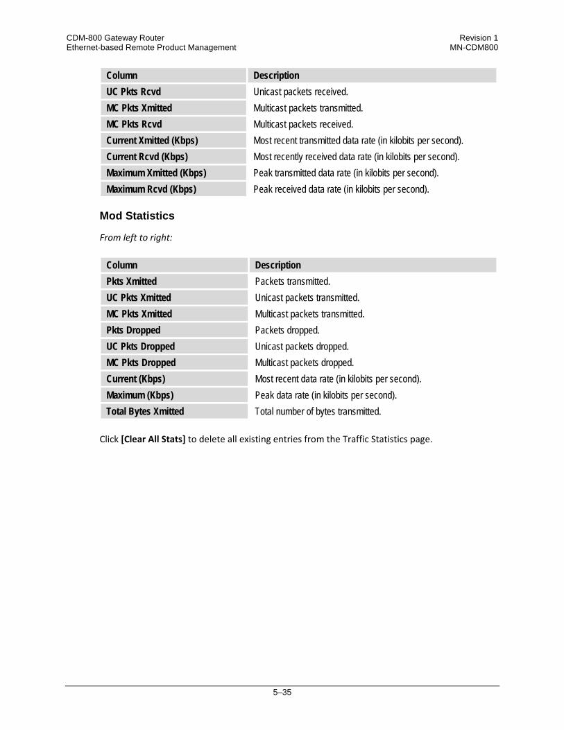
CDM-800 Gateway Router Revision 1 Ethernet-based Remote Product Management MN-CDM800
5–35
Column Description UC Pkts Rcvd Unicast packets received. MC Pkts Xmitted Multicast packets transmitted. MC Pkts Rcvd Multicast packets received. Current Xmitted (Kbps) Most recent transmitted data rate (in kilobits per second). Current Rcvd (Kbps) Most recently received data rate (in kilobits per second). Maximum Xmitted (Kbps) Peak transmitted data rate (in kilobits per second). Maximum Rcvd (Kbps) Peak received data rate (in kilobits per second).
Mod Statistics
From left to right:
Column Description Pkts Xmitted Packets transmitted. UC Pkts Xmitted Unicast packets transmitted. MC Pkts Xmitted Multicast packets transmitted. Pkts Dropped Packets dropped. UC Pkts Dropped Unicast packets dropped. MC Pkts Dropped Multicast packets dropped. Current (Kbps) Most recent data rate (in kilobits per second). Maximum (Kbps) Peak data rate (in kilobits per second). Total Bytes Xmitted Total number of bytes transmitted.
Click [Clear All Stats] to delete all existing entries from the Traffic Statistics page.
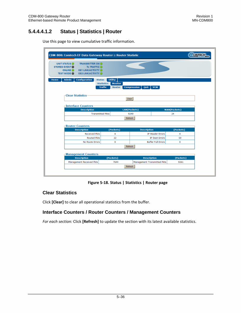
CDM-800 Gateway Router Revision 1 Ethernet-based Remote Product Management MN-CDM800
5–36
5.4.4.4.1.2 Status | Statistics | Router
Use this page to view cumulative traffic information.
Figure 5‐18. Status | Statistics | Router page
Clear Statistics
Click [Clear] to clear all operational statistics from the buffer.
Interface Counters / Router Counters / Management Counters
For each section: Click [Refresh] to update the section with its latest available statistics.

CDM-800 Gateway Router Revision 1 Ethernet-based Remote Product Management MN-CDM800
5–37
5.4.4.4.1.3 Status | Statistics | Compression
This page is operational only when the optional Tx and Rx Payload and Header are installed and enabled.
Use this page to view read‐only cumulative WAN, Payload Compression, and Header Compression statistics.
Figure 5‐19. Status | Statistics | Compression page
Clear Compression Counters
Click [Clear] to clear all compression statistics from the buffer.
WAN / Payload Compression / Detailed Compression Statistics
Click [Refresh] to update the page with the latest available statistics.

CDM-800 Gateway Router Revision 1 Ethernet-based Remote Product Management MN-CDM800
5–38
5.4.4.4.1.4 Status | Statistics | QoS
The appearance of this page changes depending on the selected QoS Control Mode.
(Top) Page with QoS Control Mode = OFF, Max/Pri(ority), or Min/Max (Bottom) Page with QoS Control Mode = DiffServ (Banner, VFP, Menu Bar not shown)
Figure 5‐20. Status | Statistics | QoS page

CDM-800 Gateway Router Revision 1 Ethernet-based Remote Product Management MN-CDM800
5–39
The Clear Statistic, Total For All Groups, Group Table, and Clear QoS Counters sections are typical for all ‘Status | Statistic | QoS’ page configurations.
Clear Statistic
Click [Clear] to clear all operational statistics from the buffer.
Total For All Groups
See the ‘Configuration | WAN | QoS’ page for the definition of the terms used in this table. Click [Refresh ] to update this section with the latest available statistics.
Group Table
This section is active only when QoS Control Mode is set to DiffServ. See the ‘Configuration | WAN | QoS’ page for the definition of the terms used in this section. Click Select to activate a desired group (when more than one group has been created). Otherwise, if only a single group is found, operation defaults to this selection. Click [Refresh] to update this section with the latest available statistics.
Clear QoS Counters
Click [Clear] to clear all QoS counters from the buffer.
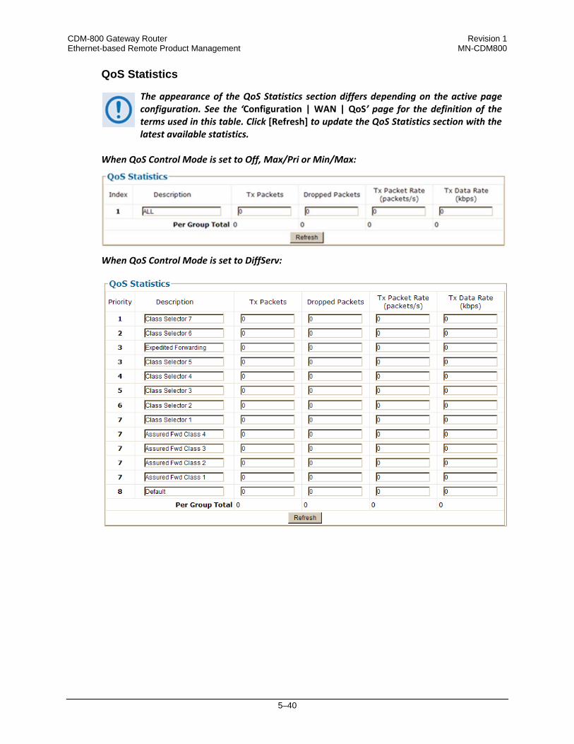
CDM-800 Gateway Router Revision 1 Ethernet-based Remote Product Management MN-CDM800
5–40
QoS Statistics
The appearance of the QoS Statistics section differs depending on the active page configuration. See the ‘Configuration | WAN | QoS’ page for the definition of the terms used in this table. Click [Refresh] to update the QoS Statistics section with the latest available statistics.
When QoS Control Mode is set to Off, Max/Pri or Min/Max: When QoS Control Mode is set to DiffServ:

CDM-800 Gateway Router Revision 1 Ethernet-based Remote Product Management MN-CDM800
5–41
5.4.4.4.1.5 Status | Statistics | VCM (Variable Coding and Modulation)
VCM allows different MODCODs for different users and applications sharing a common outbound. The MODCODs are statically assigned based on link budget. Use this page to view read‐only cumulative VCM statistics.
Figure 5‐21. Status | Statistics | VCM page
Clear Counters
Click [Clear] to clear all VCM statistics from the buffer.
VCM Statistics
From left to right:
Column Description Max MODCOD MODCOD. Frames Sent (frames) Number of DVB-S2 base band frames transmitted for this MODCOD.

CDM-800 Gateway Router Revision 1 Ethernet-based Remote Product Management MN-CDM800
5–42
Column Description Percentage of Total (%) Percentage of the total number of DVB-S2 base band frames
transmitted. Average Throughput (kbps) Amount of data in Kbps being transmitted through this MODCOD. Max Throughput (kbps) Maximum amount of data in Kbps transmitted through this MODCOD.
Click [Refresh] to update this table with the latest available VCM statistics.
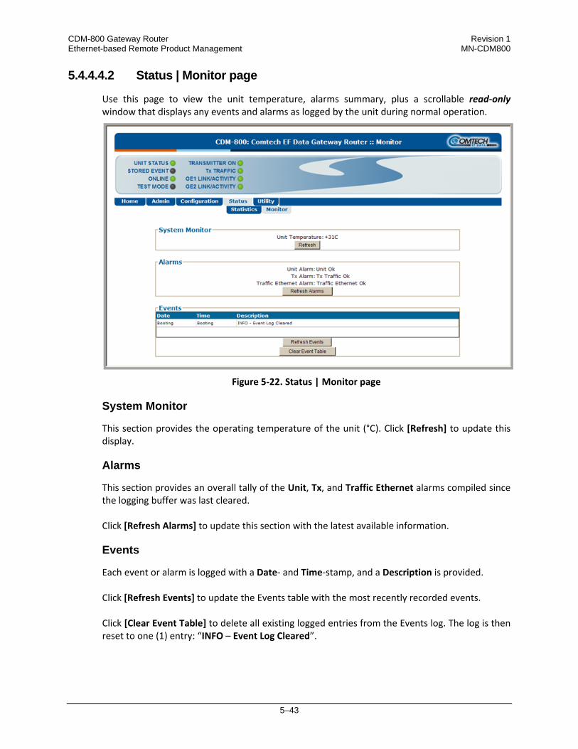
CDM-800 Gateway Router Revision 1 Ethernet-based Remote Product Management MN-CDM800
5–43
5.4.4.4.2 Status | Monitor page
Use this page to view the unit temperature, alarms summary, plus a scrollable read‐only window that displays any events and alarms as logged by the unit during normal operation.
Figure 5‐22. Status | Monitor page
System Monitor
This section provides the operating temperature of the unit (°C). Click [Refresh] to update this display.
Alarms
This section provides an overall tally of the Unit, Tx, and Traffic Ethernet alarms compiled since the logging buffer was last cleared. Click [Refresh Alarms] to update this section with the latest available information.
Events
Each event or alarm is logged with a Date‐ and Time‐stamp, and a Description is provided. Click [Refresh Events] to update the Events table with the most recently recorded events. Click [Clear Event Table] to delete all existing logged entries from the Events log. The log is then reset to one (1) entry: “INFO – Event Log Cleared”.

CDM-800 Gateway Router Revision 1 Ethernet-based Remote Product Management MN-CDM800
5–44
5.4.4.5 Utility Pages
Click the Utility or Reboot tab to continue.
5.4.4.5.1 Utility | Utility
Use this page to access a variety of top‐level system operation controls, stored unit configurations, and test utilities.
Figure 5‐23. Utility | Utility page

CDM-800 Gateway Router Revision 1 Ethernet-based Remote Product Management MN-CDM800
5–45
Modem
• Unit Name – The product (e.g., CDM‐800) is identified here.
• System Contact / System Location – E‐mail and telephone contact information for Comtech EF Data Customer Support are provided here.
Enter the desired settings. Click [Submit] to save.
• Set Time (hh:mm:ss) – Use the HH:MM:SS time format to set the time, where HH=hour [00
to 23]; MM=minutes [00 to 59]; and SS=seconds [00 to 59]).
• Set Date (dd/mm/yy) – Use the DD/MM/YY European time format to set the date, where DD=day [01 to 31]; MM=month [01 to 12]; and YY=year [00 to 99].
Set the time and date, and then click [Submit] to save.
• Circuit ID – Enter a Circuit ID string consisting of 4 to 24 characters, and then click [Submit]
to save.
• G.703 Clock Extended Mode – Use the drop‐down menu to select this operating mode as Off or On, and then click [Submit] to save.
• 10 MHz Internal Adjustment – Enter a value from (‐)999 to (+)999 to set the adjustment for
the Internal 10 MHz High Stability Reference, and then click [Submit] to save. • Test Mode – Use the drop‐down menu to select this operating mode as follows:
o Normal Mode – This mode clears any test modes or loopbacks, and returns the unit to its operational state.
o Tx CW – This test mode forces the modulator to transmit a pure carrier (unmodulated).
o Tx Alt 1/0 – This test mode forces the modulator to transmit a carrier modulated with an alternating 1,0,1,0 pattern, at the currently selected symbol rate. This causes two discrete spectral lines to appear, spaced at +/‐ half the symbol rate, about the carrier frequency. Use this mode to check the carrier suppression of the modulator.
Select the desired mode. Click [Submit] to save.
Save/Load Configuration
This section allows the user to save, and then load (recall) up to 10 configuration sets: • To save a configuration set:
o First, adjust all operational configuration parameters to suit.

CDM-800 Gateway Router Revision 1 Ethernet-based Remote Product Management MN-CDM800
5–46
o Then, use the top (Save) Select Location dropdown to select 1 through 10.
o Finally, click [Save Configuration] to store the configuration settings.
• To load (recall) a configuration set: o First, use the bottom (Load) Select Location dropdown to select 1 through 10.
o Then, click [Load Configuration] to recall the selected configuration settings.
BERT Config
(Where BERT is the acronym for Bit Error Rate Test) Use the drop‐down menus to: • Configure the Tx BERT State as On or Off. • Configure the Tx or Rx BERT Pattern as 2^23‐1 (223‐1) or 2047. • Set Error Insert(ion) as either Off or 10E‐3. Click [Submit] to save the BERT settings and execute the test. Once the Tx BERT is executed, the entire outbound carrier transmits a BERT pattern.
All IP communications are halted during this test. Note also that the Rx BERT State for the CDM‐840 Remote Router must be enabled to properly receive and monitor the BERT pattern.
Redundancy
• Current Redundancy State (read‐only) – Status is listed as On Line or Off Line.
• Offline Unit Status (read‐only) – This indicates the status of the offline unit.
If the unit is not connected to a redundancy switch, the status is listed as No_1F1. Otherwise, its status is listed as On Line or Off Line.
If the unit is part of a 1:1 or 1:N redundant pair of CDM‐800s, and this unit is currently On Line, click [Force Redundancy Switch] to cause the unit to switch to standby.

CDM-800 Gateway Router Revision 1 Ethernet-based Remote Product Management MN-CDM800
5–47
5.4.4.5.2 Utility | Reboot
Use this page to perform a soft reboot of the CDM‐800. Note that the function of this page is identical to the System Reboot section of the ‘Admin | Firmware’ page described earlier.
Figure 5‐24. Utility | Reboot page
System Reboot
Click [Reboot] to reboot the unit. A dialogue box appears to prompt continuation or cancellation of the reboot process: Click [OK] to continue the reboot process, or [Cancel] to abort the process and return to the ‘Utility | Reboot’ page. Once the reboot process resumes, the ‘Utility | Reboot’ page is replaced with the dynamic message “Please wait... CDM‐800 is rebooting. Login will be required in XX seconds” – the time count decrements to 0 seconds before the unit reboots. After the reboot, login is required once again to resume use of the Web Server Interface.

CDM-800 Gateway Router Revision 1 Ethernet-based Remote Product Management MN-CDM800
5–48
Notes:

6–1
Chapter 6. SERIAL-BASED REMOTE PRODUCT MANAGEMENT
6.1 Introduction
Serial‐based Remote Product Management of the CDM‐800 Gateway Router is available using the rear panel ‘CONSOLE’ port.
1. To proceed with Serial‐based Remote Product Management, assumptions are made that:
• The CDM‐800 Gateway Router is operating with the latest version firmware files.
• The CDM‐800 is connected to a user‐supplied Windows‐based PC as follows:
o The PC serial port is connected to the CDM‐800 rear panel ‘CONSOLE’ port using a user‐supplied serial cable.
o The PC Ethernet port is connected to the CDM‐800 rear panel ‘MANAGEMENT | FE’ 10/100 BaseT Ethernet port with a user‐supplied hub, switch, or direct Ethernet cable connection.
o The PC is running a terminal emulation program (for operation of the CDM‐800 Serial Command Line Interface) and a compatible Web browser (for operation of the CDM‐800 Web Server Interface).
• The CDM‐800 Management IP Address has been noted using the CDM‐800 Serial Command Line Interface (CLI).

CDM-800 Gateway Router Revision 1 Serial-based Remote Product Management MN-CDM800
6–2
2. USE OF THE SERIAL‐BASED REMOTE PRODUCT MANAGEMENT INTERFACE IS RECOMMENDED ONLY FOR ADVANCED USERS. ALL OTHER USERS ARE STRONGLY ENCOURAGED TO USE THE CDM‐800 WEB SERVER INTERFACE FOR MONITOR AND CONTROL (M&C) OF THE CDM‐800. SEE CHAPTER 5. ETHERNET‐BASED REMOTE PRODUCT MANAGEMENT.
Figure 5-1. CDM-800 Serial Interface Example CDM‐800 Serial Remote Product Management is available through the EIA‐232 operational interface, where the ‘Controller’ device (the user PC or an ASCII dumb terminal) is connected directly to the ‘Target’ device (the CDM‐800 Gateway Router, via its DB‐9M ‘CONSOLE’ port). This connection makes possible serial remote monitor and control (M&C) of the CDM‐800 through its Serial Command Line Interface (CLI). Through this EIA‐232 connection (for the control of a single device), data is transmitted in asynchronous serial form, using ASCII characters. Control and status information is transmitted in packets of variable length in accordance with the structure and protocol defined later in this chapter. Access to the CLI is accomplished with a user‐supplied terminal emulator program such as Tera Term or HyperTerminal. Use this utility program to first configure serial port communication and terminal display operation: • 38400 bps (Baud Rate) • 8 Data Bits • 1 Stop Bit
• Parity = NO • Port Flow Control = NONE • Display New line Rx/Tx: CR
• Local Echo = ON
CDM-800 Gateway Router Revision 1 Serial-based Remote Product Management MN-CDM800
6–3
When the user‐supplied terminal emulator program is configured correctly, upon power‐up of the CDM‐800, the CLI Info Screen appears, followed by the CLI command prompt CDM‐800>. From here, type “help[cr]” or “?[cr]” (without the quotes) to display the CDM‐800 available commands and queries, and to review instructions for using the interface.
6.2 Remote Commands and Queries Overview
6.2.1 Basic Protocol
In an EIA‐232 configuration, the Controller device is connected directly to the Target device via a two wire‐plus‐ground connection. All data is transmitted in framed packets as asynchronous serial characters, suitable for transmission and reception to the Controller using a universal asynchronous receiver/transmitter (UART). Controller‐to‐Target data is carried via EIA‐232 electrical levels on one conductor, and Target‐to‐Controller data is carried in the other direction on the other conductor:
• Controller‐to‐Target: The Controller device (e.g., the user PC/CLI) is used to transmit instructions (commands) to – or to request information from (queries) – the Target device (i.e., the CDM‐800).
• Target‐to‐Controller: The Target, in return, only transmits response information to the Controller when specifically directed by
the Controller. For Serial Remote Control, all issued commands (Controller‐to‐Target) require a response (Target‐to‐Controller). This response is either to return data that has been queried by the Controller, or to confirm the Target’s receipt of a command to change the Target’s configuration.
6.2.2 Packet Structure
The exchange of information is transmitted, Controller‐to‐Target and Target‐to‐Controller, in packets. Each packet contains a finite number of bytes consisting of printable ASCII characters, excluding ASCII code 127 (DELETE). In this context, the Carriage Return and Line Feed characters are considered printable. With one exception, all messages from Controller‐to‐Target require a response – this will be either to return data that has been requested by the Controller, or to acknowledge reception of an instruction to change the configuration of the Target.

CDM-800 Gateway Router Revision 1 Serial-based Remote Product Management MN-CDM800
6–4
Controller-to-Target (Issued Command or Query)
Start of Packet Target Address Address Delimiter Instruction Code Code Qualifier Optional Arguments End of Packet
< ASCII code 60
(1 character)
0000 (default)
(4 characters)
/ ASCII code 47
(1 character)
(3 characters)
= or ? ASCII codes 61 or 63
(1 character)
(n characters)
Carriage Return ASCII code 13
(1 character) Packet Example: <0000/RSH=30[cr]
Target-to-Controller (Response to Command or Query)
Start of Packet Target Address Address Delimiter Instruction Code Code Qualifier Optional Arguments End of Packet
> ASCII code 62
(1 character)
0000 (default)
(4 characters)
/ ASCII code 47
(1 character)
(3 characters)
= or ? ASCII codes 61 or 63
(1 character)
(n characters)
Carriage Return ASCII code 13
(1 character) Packet Example: >0000/BBU=107[cr][lf] Detailed description of the packet components follow.
6.2.2.1 Start of Packet
• Controller‐to‐Target: This is the character ‘<’ (ASCII code 60).
• Target‐to‐Controller: This is the character ‘>’ (ASCII code 62). The ‘<’ and ‘>’ characters indicate the start of packet. They may not appear anywhere else within the body of the message.
CDM-800 Gateway Router Revision 1 Serial-based Remote Product Management MN-CDM800
6–5
6.2.2.2 Target Address
In EIA‐232 applications, this value is set to 0000.
The Target Address designates the packet destination. The Controller does not have its own address. After the Controller sends a packet with the designated Target Address, the Target responds to the Controller, using this same address, to indicate the source of the packet.
6.2.2.3 Address Delimiter
This is the “forward slash” character '/ ' (ASCII code 47).
6.2.2.4 Instruction Code
This is a three‐character alphabetic sequence that identifies the message subject. Wherever possible, the instruction codes have been chosen to have some significance – e.g., MLC for Management Link Configuration, IPA for Management IP Address, etc. This aids in the readability of the message, should it be displayed in its raw ASCII form. Only upper case alphabetic characters may be used (‘A’ to ‘Z’, ASCII codes 65 ‐ 90).

CDM-800 Gateway Router Revision 1 Serial-based Remote Product Management MN-CDM800
6–6
6.2.2.5 Instruction Code Qualifier
This is a single character that further qualifies the preceding instruction code. Code Qualifiers obey the following rules: From Controller‐to‐Target, the only permitted characters are:
Character Definition = (ASCII code 61)
This character is used as the Assignment Operator (AO). It establishes that the Instruction Code that precedes it is to be used as a command to assign or configure operation. The instruction set that follows serves to assign the Target’s new parameter setting or operational value. Example: In a message from Controller-to-Target, IG1=aaa.bbb.ccc.ddd/yy means “set the GE Port IP address to aaa.bbb.ccc.ddd/yy”
? (ASCII code 63)
This character is used as the Query Operator (QO). It establishes that the Instruction Code that precedes it is to be used as a query that returns the Target’s current configured parameter setting or operational value. Example: From Controller-to-Target, IG1? means “what’s the current GE Port IP address?”
From Target‐to‐Controller, the only permitted characters are:
Character Definition
= (ASCII code 61)
This character is used in two ways: a. If the Controller sends a query to the Target – for example, CMD? (meaning “what’s current value of this parameter?”)
– the Target responds with CMD=xxx, the value for that queried parameter. b. If the Controller sends an instruction to set a parameter to a particular value, and the value sent is valid, the Target
acknowledges the message and responds with CMD= (with no message arguments).
? (ASCII code 63)
If the Controller sends an instruction to set a parameter to a particular value, and the value sent is not valid, the Target then acknowledges the message and responds with, for example, CMD? (with no message arguments). This indicates that there was an error in the message sent by the Controller.

CDM-800 Gateway Router Revision 1 Serial-based Remote Product Management MN-CDM800
6–7
Character Definition ! (ASCII code 33)
If the Controller sends an instruction code that the Target does not recognize, the Target responds by echoing the invalid instruction, followed by ! Example: CMD!
* (ASCII code 42)
If the Controller sends the command to set a parameter to a particular value, and the value sent is valid BUT the router will not permit that particular parameter to be changed at present, the Target acknowledges the message and responds with, for example, CMD* (with message arguments).
# (ASCII code 35)
If the Controller sends a correctly formatted command, BUT the unit is not in Remote Mode, it does not allow reconfiguration and responds, for example, with CMD#.
6.2.2.6 Optional Message Arguments
Arguments are not required for all messages. Arguments are ASCII codes for the characters ‘0’ to ‘9’ (ASCII codes 48 to 57), period ‘.’ (ASCII code 46), and comma ‘,’ (ASCII code 44).
6.2.2.7 End of Packet
Controller‐to‐Target: This is the ‘Carriage Return’ ([CR]) character (ASCII code 13). Target‐to‐Controller: This is the two‐character sequence ‘Carriage Return’, ‘Line Feed’ ([cr][lf]) (ASCII codes 13 and 10). Both indicate the valid termination of a packet.
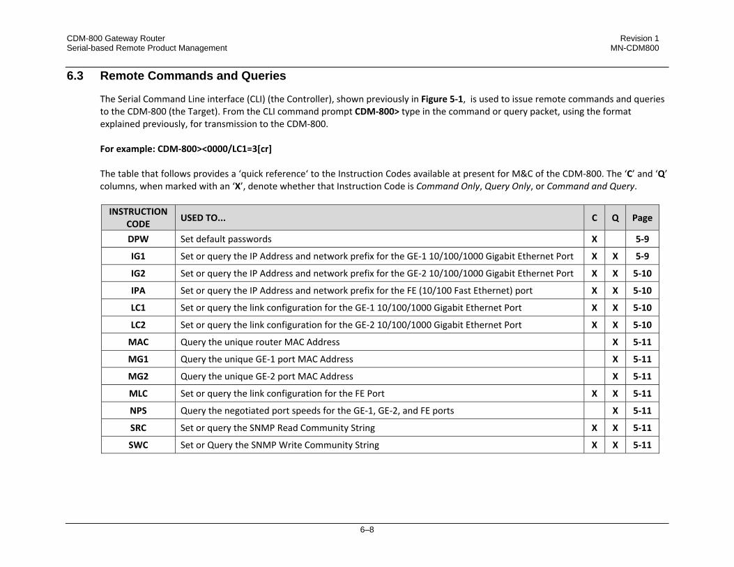
CDM-800 Gateway Router Revision 1 Serial-based Remote Product Management MN-CDM800
6–8
6.3 Remote Commands and Queries
The Serial Command Line interface (CLI) (the Controller), shown previously in Figure 5‐1, is used to issue remote commands and queries to the CDM‐800 (the Target). From the CLI command prompt CDM‐800> type in the command or query packet, using the format explained previously, for transmission to the CDM‐800. For example: CDM‐800><0000/LC1=3[cr] The table that follows provides a ‘quick reference‘ to the Instruction Codes available at present for M&C of the CDM‐800. The ‘C’ and ‘Q’ columns, when marked with an ‘X’, denote whether that Instruction Code is Command Only, Query Only, or Command and Query. INSTRUCTION
CODE USED TO... C Q Page
DPW Set default passwords X 5‐9
IG1 Set or query the IP Address and network prefix for the GE‐1 10/100/1000 Gigabit Ethernet Port X X 5‐9
IG2 Set or query the IP Address and network prefix for the GE‐2 10/100/1000 Gigabit Ethernet Port X X 5‐10
IPA Set or query the IP Address and network prefix for the FE (10/100 Fast Ethernet) port X X 5‐10
LC1 Set or query the link configuration for the GE‐1 10/100/1000 Gigabit Ethernet Port X X 5‐10
LC2 Set or query the link configuration for the GE‐2 10/100/1000 Gigabit Ethernet Port X X 5‐10
MAC Query the unique router MAC Address X 5‐11
MG1 Query the unique GE‐1 port MAC Address X 5‐11
MG2 Query the unique GE‐2 port MAC Address X 5‐11
MLC Set or query the link configuration for the FE Port X X 5‐11
NPS Query the negotiated port speeds for the GE‐1, GE‐2, and FE ports X 5‐11
SRC Set or query the SNMP Read Community String X X 5‐11
SWC Set or Query the SNMP Write Community String X X 5‐11

CDM-800 Gateway Router Revision 1 Serial-based Remote Product Management MN-CDM800
6–9
These Instruction Codes are explained in complete detail in the tables that follow. Note that the Target‐to‐Controller Instruction Code Qualifiers, described earlier, that appear in the “Response to Command” column carry the following meanings: = Message OK. ? Received OK, but invalid arguments were found. * Message OK, but not permitted in current mode. # Message OK, but unit is not in Remote mode. ! Invalid instruction.
Parameter Type
Command (Instruction & Qualifier)
Number of Arguments Description of Arguments Response to
Command Query
(Instruction & Qualifier)
Response to Query
Default Passwords
DPW= N/A Command Only. Resets the admin username/password to: Username = “comtech” Password = “comtech”
DPW= DPW? DPW* DPW#
N/A N/A
GE1 Address IG1= 18 bytes numerical Command or Query. Sets the IP Address and network prefix for the 10/100/1000 BaseT GE1 Ethernet port, in the form aaa.bbb.ccc.ddd/yy, where:
(Permitted ranges – cannot all be zero) aaa = 0-223 bbb = 0-255 ccc = 0-255 ddd = 0-255 yy = network prefix (range: 8 to 31)
Other restrictions: If aaa>191, prefix may not be less than 24. If aaa>127, prefix may not be less than 16. Example: IG1=010.006.030.001/24
IG1= IG1? IG1* IG1#
IG1? IG1=xxx.xxx.xxx.xxx/yy (see Description of Arguments)

CDM-800 Gateway Router Revision 1 Serial-based Remote Product Management MN-CDM800
6–10
Parameter Type
Command (Instruction & Qualifier)
Number of Arguments Description of Arguments Response to
Command Query
(Instruction & Qualifier)
Response to Query
GE2 Address IG2= 18 bytes numerical Command or Query. Sets the IP Address and network prefix for the 10/100/1000 BaseT GE2 Ethernet port, in the form aaa.bbb.ccc.ddd/yy, where:
(Permitted ranges – cannot all be zero) aaa = 0-223 bbb = 0-255 ccc = 0-255 ddd = 0-255 yy = network prefix (range: 8 to 31)
Other restrictions: If aaa>191, prefix may not be less than 24. If aaa>127, prefix may not be less than 16. Example: IG2=010.006.030.001/24
IG2= IG2? IG2* IG2#
IG2? IG2=xxx.xxx.xxx.xxx/yy (see Description of Arguments)
Management IP Address
IPA= 18 bytes numerical Command or Query. Sets the IP Address and network prefix for the 10/100 Base T Ethernet management port, in the form aaa.bbb.ccc.ddd/yy, where:
(Permitted ranges – cannot all be zero) aaa = 0-223 bbb = 0-255 ccc = 0-255 ddd = 0-255 yy = network prefix (range: 8 to 31)
Example: IPA=010.006.030.001/24
IPA= IPA? IPA* IPA#
IPA? IPA=xxx.xxx.xxx.xxx/yy (see Description of Arguments)
GE1 Link Configuration
LC1= 1 byte, value 0 thru 5
Command or Query. GE1 Interface mode, where: 0 = Auto Negotiate 1 = 1000Mbps -Full Duplex 2 = 100Mbps – Full Duplex 3 = 100Mbps – Half Duplex 4 = 10Mbps – Full Duplex 5 = 10Mbps – Half Duplex
LC1= LC1? LC1* LC1#
LC1? LC1=x (see Description of Arguments)
GE2 Link Configuration
LC2= 1 byte, value 0 thru 5
Command or Query. GE2 Interface mode, where: 0 = Auto Negotiate 1 = 1000Mbps -Full Duplex 2 = 100Mbps – Full Duplex 3 = 100Mbps – Half Duplex 4 = 10Mbps – Full Duplex 5 = 10Mbps – Half Duplex
LC2= LC2? LC2* LC2#
LC2? LC2=x (see Description of Arguments)

CDM-800 Gateway Router Revision 1 Serial-based Remote Product Management MN-CDM800
6–11
Parameter Type
Command (Instruction & Qualifier)
Number of Arguments Description of Arguments Response to
Command Query
(Instruction & Qualifier)
Response to Query
Management MAC Address
N/A 12 bytes, alpha- numerical
Query only. Returns the unique MAC Address for the modem. Example: MAC=00:06:B0:00:01:C2
N/A MAC? MAC=aabbccddeeff (see Description of Arguments)
GE1 MAC Address
N/A 12 bytes, alpha- numerical
Query only. Returns the unique GE1 MAC Address. Example: MG1=00:06:B0:00:01:C2
N/A MG1? MG1=aabbccddeeff (see Description of Arguments)
GE2 MAC Address
N/A 12 bytes, alpha- numerical
Query only. Returns the unique GE2 MAC Address. Example: MG2=00:06:B0:00:01:C2
N/A MG2? MG2=aabbccddeeff (see Description of Arguments)
Management Link Configuration
MLC= 1 byte, value 0 thru 5
Command or Query. Management Interface mode, where:
0 = Auto Negotiate 1 = reserved 2 = 100Mbps – Full Duplex 3 = 100Mbps – Half Duplex 4 = 10Mbps – Full Duplex 5 = 10Mbps – Half Duplex
MLC = MLC? MLC * MLC #
MLC? MLC =x (see Description of Arguments)
Actual Negotiated Port Speed
N/A None Query only. Returns actual negotiated port speed in the form abcd, where:
a = GE 1 negotiated port speed. b = GE 2 negotiated port speed. c = the management port negotiated port speed.
a, b, c, d have the following values: 0 = Link down 1 = 100 Full 2 = 100 Half 3 = 10 Full 4 = 10 Half 5 = 1000 Full
N/A NPS? NPS=abc (see Description of Arguments)
SNMP Read Community
SRC= 16 bytes, characters, no spaces
Command or Query. SNMP read community string. Empty string is not allowed Example: <1/SRC=public
SRC = SRC!
SRC?
SRC =x (see Description of Arguments)
SNMP Write Community
SWC=
16 bytes, characters, no spaces
Command or Query. SNMP write community string. Empty string is not allowed Example: <1/SWC =public
SWC = SWC!
SWC? SWC =x (see Description of Arguments)
CDM-800 Gateway Router Revision 1 Serial-based Remote Product Management MN-CDM800
6–12
Notes:

A–1
Appendix A. FAST
A.1 FAST Overview
The CDM‐800 Gateway Router incorporates a number of optional features. In order to permit a lower initial cost, the unit may be purchased with only the desired features enabled. If, at a later date, the user wishes to upgrade the functionality of a unit, Comtech EF Data provides Fully Accessible System Topology (FAST), which permits the purchase and installation of options through special authorization codes. These unique Fast Access Codes may be purchased from Comtech EF Data during normal business hours, and then loaded into the unit using the Web Server Interface (accessible via the CDM‐800 rear panel ‘FE’ port). FAST System Theory: FAST facilitates on‐location upgrade of the operating feature set without removing a unit from the setup. With FAST technology, operators have maximum flexibility for enabling functions as they are required. FAST allows an operator to order a unit precisely tailored for the initial application. When service requirements change, the operator can upgrade the topology of the unit to meet those requirements within minutes. This accelerated upgrade can be accomplished because of FAST’s extensive use of the programmable logic devices incorporated into Comtech EF Data products. FAST Implementation: Comtech EF Data’s FAST system is factory‐implemented in the unit. All FAST options are available through the basic platform unit at the time of order – FAST allows immediate activation of available options, after confirmation by Comtech EF Data, through the Web Server Interface. FAST Accessible Options: Hardware options can be ordered and installed either at the factory or in the field. In the field, the operator can select options that can be easily activated, depending on the current hardware configuration of the unit. The unique access code that is purchased from Comtech EF Data enables configuration of the available hardware.

CDM-800 Gateway Router Revision 1 Appendix A MN-CDM800
A–2
A.2 FAST Activation via the Web Server Interface
Refer to Sect. 5.4.4.2.3 Admin | FAST for the complete information on using the CDM‐800 Web Server Interface to activate FAST Features.
Figure A‐1. CDM‐800 Web Server (HTTP) Interface – ‘ADMIN | FAST’ page
The CDM‐800 Web Server Interface ‘Admin | FAST’ page (Figure A‐1) is used for complete management of FAST Features. The page lists the status and availability of all FAST options; upgrade of the router features using the FAST Code entry/option activation controls is accomplished here as well.
B–1
Appendix B. FEC (FORWARD ERROR CORRECTION)
B.1 Introduction
The method of FEC (Forward Error Correction) used by the CDM‐800 Gateway Router is based upon the DVB‐S2 standard for QPSK, 8PSK, 16APSK and 32APSK with concatenated Low Density Parity Code (LDPC) and Bose‐Chaudhuri‐Hocquenghem (BCH).
B.2 DVB-S2: LDPC and BCH
The DVB‐S2 specification has defined a new generation of performance that boosts throughput by about 30% over DVB‐S using the same amount of bandwidth. This new type of coding and modulation far exceeds the capability of concatenated Viterbi and Reed Solomon coding. LDPC and BCH is also a concatenated error correction technique. LDPC is a very powerful coding scheme with significant, Near‐Shannon Bound Performance. In some cases, as the carrier‐to‐noise ratio increases, the LDPC error correction starts flaring toward an error floor so BCH error correction follows LDPC and eliminates the flare for any practical range of error rates. LDPC also functions differently than Viterbi decoding by using iterative decoding. In this process the data initially corrected by the LDPC decoder is re‐encoded and run through the decoder again to correct additional errors. Key to this is the soft decision output from the LDPC decoder and a high‐speed processor operating at a rate much higher than the data rate. The LDPC decoder runs the iterative process as many times as possible before corrected data is finally output to make way for a new block of data entering the decoder. LDPC also uses interleaving to spread the errors. In contrast, Viterbi error correction operates by passing data through the convolutional error correction process using a single error correction pass.
B.2.1 Range of Data Rates
For the range of Data Rates, refer to Sect. 1.4 SUMMARY OF SPECIFICATIONS.
B.2.2 BER, QEF, Eb/No, Es/No Spectral Efficiency, and Occupied Bandwidth
Depending upon the operating mode, the DVB standard uses different modes of specifying performance with a unit in IF Loop and Additive White Gaussian Noise (AWGN):

CDM-800 Gateway Router Revision 1 Appendix B MN-CDM800
B–2
• DVB‐S2 standard: "Quasi Error Free" (QEF) is defined as "less than one uncorrected error‐event per transmission hour at the level of a 5 Mbits/s single TV service decoder", approximately corresponding to a Transport Stream Packet Error Ratio equal to a PER<10‐7 before demultiplexer. A packet is defined as block of 188 byte MPEG frame size data.
• Es/No vs. Eb/No: The DVB‐S2 standard commonly refers to the use of Es/No instead of Eb/No. When links operate at a constant symbol rate this is a good method for comparing the performance of different modulation types and code rates.
The relation between the two quantities is given by:
Eb/No = Es/No – 10log(Spectral Efficiency)
• Occupied Bandwidth: Occupied bandwidth is defined as the bandwidth between ‐10 dB points of the power spectral density, which are approximately:
Occupied Bandwidth = 1.19 x Symbol Rate, for 35% Rolloff
= 1.15 x Symbol Rate, for 25% Rolloff
= 1.12 x Symbol Rate, for 20% Rolloff
* Taken at the -10 dB points on the plot of power spectral density, the occupied bandwidth is 1.19 x Symbol Rate for 35%, and 1.15 x Symbol Rate for 25%.
B.3 CDM-800 Error Performance Characteristics
On the pages that follow, Figure B‐1 through Figure B‐4 illustrate the guaranteed error performance characteristics of the CDM‐800 for DVB‐S2 operation while receiving with Normal frames (64,800 bits), Pilots ON.

CDM-800 Gateway Router Revision 1 Appendix B MN-CDM800
B–3
Figure B-1. DVB-S2 QPSK Packet Error Rate versus Es/No
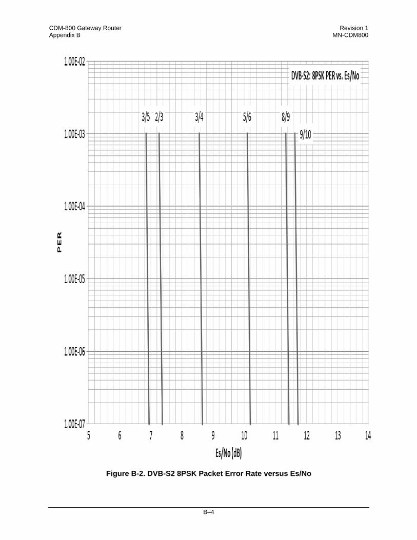
CDM-800 Gateway Router Revision 1 Appendix B MN-CDM800
B–4
Figure B-2. DVB-S2 8PSK Packet Error Rate versus Es/No

CDM-800 Gateway Router Revision 1 Appendix B MN-CDM800
B–5
Figure B-3. DVB-S2 16APSK Packet Error Rate versus Es/No

CDM-800 Gateway Router Revision 1 Appendix B MN-CDM800
B–6
Figure B-4. DVB-S2 32APSK Packet Error Rate versus Es/No

METRIC CONVERSIONS
Units of Length
Unit Millimeter Centimeter Inch Foot Yard Meter Kilometer Mile
1 millimeter 1 0.1 0.0394 0.0033 0.0011 0.001 1 x 10⁻⁶ 6.214 x 10⁻⁷
1 centimeter 10 1 0.3937 0.0328 0.0109 0.01 1 x 10⁻⁵ 6.214 x 10⁻⁶
1 inch 25.4 2.54 1 0.0833 0.0278 0.0254 2.54 x 10⁻⁵ 1.578 x 10⁻⁵
1 foot 304.8 30.48 12 1 0.3333 0.3048 3.048 x 10⁻⁴ 1.894 x 10⁻⁴
1 yard 914.4 91.44 36 3 1 0.9144 9.144 x 10⁻⁴ 5.682 x 10⁻⁴
1 meter 1000 100 39.37 3.2808 1.0936 1 0.001 6.214 x 10⁻⁴
1 kilometer 1 x 10⁶ 1 x 10⁵ 3.938 x 10⁴ 3.281 1093 1000 1 0.6214
1 mile 1.609 x 10⁶ 1.609 x 10⁵ 6.336 x 10⁴ 5280 1760 1609 1.609 1
Temperature Conversions
Units of Weight
Unit Gram Ounce Avoirdupois
Ounce Troy
Pound Avoirdupois
Pound Troy Kilogram
1 gram 1 0.03527 0.03215 0.002205 0.002679 0.001
1 oz. avoir. 28.35 1 0.9115 0.0625 0.07595 0.02835
1 oz. troy 31.10 1.097 1 0.06857 0.08333 0.03110
1 lb. avoir. 453.6 16.0 14.58 1 1.215 0.4536
1 lb. Troy 373.2 13.17 12.0 0.8229 1 0.3732
1 kilogram 1000 35.27 32.15 2.205 2.679 1
Temperature ° Fahrenheit ° Centigrade
Water freezes 32 0
Water boils 212 100
Absolute zero -459.69 -273.16
Formulas
° C = (F - 32) * 0.555
° F = (C * 1.8) + 32

2114 WEST 7TH STREET TEMPE ARIZONA 85281 USA 480 • 333 • 2200 PHONE
480 • 333 • 2161 FAX