Embed Size (px)
Citation preview

1
TLEN 5320 Experiment 14
CDMA System Analysis II
Authors: Timothy X Brown, Silvana Susi, Sukhjinder Singh University Of Colorado, Boulder
PurposeThis experiment allows the student to gain a meaningful understanding of theIS-95 system specifications by observing the relationship between thedifferent group categories of the PN Offset: Active Set, Candidate Set, andNeighbor Set, and the Layer 3 messages between the mobile and the basestation while the terminal is active in the system.
Equipment- RSAT-2000 CDMA/AMPS equipment- A Portable Computer or desktop with OptimEyes Software
Introduction
IS-95Interim Standard 95 (IS-95) is a U.S. digital cellular system based on CDMAthat allows each user within a cell and in adjacent cells to use the same radiochannel. Each IS-95 channel occupies 1.23MHz of spectrum in each one-waylink, which corresponds to 41 30kHz AMPS channels.1
The user data is spread to a channel chip rate of 1.2288MHz. IS-95 uses adifferent modulation and spreading technique for the forward and reverselinks. On the forward link, the base station simultaneously transmits the userdata for all mobiles in the cell by using different spreading sequence for eachmobile. The user data is encoded, interleaved, and spread by one of sixty-four orthogonal spreading sequences (Walsh functions). To avoidinterference, all signals in a particular cell are scrambled using apseudorandom sequence of length 215 chips.2 CDMA base stations transmitinformation in four logical channel formats: pilot channels, sync channels,paging channels, and traffic channels.On the reverse link, all mobiles respond in an asynchronous fashion. Theuser data is encoded, interleaved, and then blocks of 6 bits are mapped toone of the 64 orthogonal Walsh functions. Finally, the data is spread by auser specific code of 42 bits (channel identifier) and the base stationpseudorandom sequence of length 215 chips. The reverse channel isorganized in access channels and traffic channels.3
1 Theodore Rappaport, Wireless Communications. Principles & Practice (Upper Saddle River, N.J.: Prentice Hall,1999), 519.
2 Ibid., 520.3 Ibid., 520 Ą 521.

2
TLEN 5320 Experiment 14
At both the base station and the terminal, Rake receivers are used to resolveand combine multipath components, in order to improve the link quality. In IS-95, a three-finger Rake receiver is used at the base station.4
IS-95 Logical ChannelsPilot Channel: is used by the base station to provide a reference for all mobilestations. It provides a phase reference for coherent demodulation at themobile receiver to enable coherent detection. It is assigned the Walsh codeW0. The pilot signal level for all base stations is kept about 4 to 6 dB higherthan the traffic channel with a constant signal power. The pilot is used forcomparisons of signal strength between different base stations to decidewhen to perform handoff. The pilot signals from all base stations use thesame PN sequences, but each base station is identified by a unique timeoffset. These offsets are in increments of 64 chips to provide 512 uniqueoffsets.5 Each terminal segregates the set of PN Offset values (and implicitlythe set of base stations) in a system into four categories:6
• The active list contains base stations currently used for trafficchannel transmissions. In a soft handoff condition, there is morethan one base station in this list.
• The candidate list consists of base stations classified by theterminal, on the basis of measured signal quality, as available fortraffic channel transmissions.
• The neighbor list is a set of nearby base stations that could soon beavailable for handoff.
• The remaining list contains the base stations that are not in any ofthe other categories.
Sync Channel: is assigned the Walsh function W32 and is used with the pilotchannel to acquire initial time synchronization. The Sync channel messageparameters are: System Identification (SID), Network Identification (NID), Pilotshort PN sequence offset index, Long-code state, System time, Offset of localtime, Daylight saving time indicator, and Paging Channel data rate (4.8 or9.6kbps).7
Paging Channel: there are up to seven paging channels that transmit controlinformation to the terminals that do not have calls in progress. The paging
4 Theodore Rappaport, Wireless Communications. Principles & Practice (Upper Saddle River, N.J.: Prentice Hall,
1999), 521.5 Vijay Garg, IS-95 CDMA and CDMA 2000: Cellular/PCS System Implementation (Prentice Hall, 1999), 113.6 David Goodman, Wireless Personal Communication Systems (Addison-Wesley, 1997), 248.7 Vijay Garg, IS-95 CDMA and CDMA 2000: Cellular/PCS System Implementation (Prentice Hall, 1999), 114.
3
TLEN 5320 Experiment 14
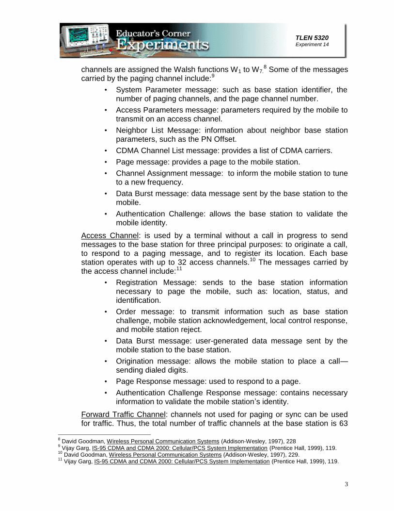
channels are assigned the Walsh functions W1 to W7.8 Some of the messages
carried by the paging channel include:9
• System Parameter message: such as base station identifier, thenumber of paging channels, and the page channel number.
• Access Parameters message: parameters required by the mobile totransmit on an access channel.
• Neighbor List Message: information about neighbor base stationparameters, such as the PN Offset.
• CDMA Channel List message: provides a list of CDMA carriers.• Page message: provides a page to the mobile station.• Channel Assignment message: to inform the mobile station to tune
to a new frequency.• Data Burst message: data message sent by the base station to the
mobile.• Authentication Challenge: allows the base station to validate the
mobile identity.Access Channel: is used by a terminal without a call in progress to sendmessages to the base station for three principal purposes: to originate a call,to respond to a paging message, and to register its location. Each basestation operates with up to 32 access channels.10 The messages carried bythe access channel include:11
• Registration Message: sends to the base station informationnecessary to page the mobile, such as: location, status, andidentification.
• Order message: to transmit information such as base stationchallenge, mobile station acknowledgement, local control response,and mobile station reject.
• Data Burst message: user-generated data message sent by themobile station to the base station.
• Origination message: allows the mobile station to place a call’sending dialed digits.
• Page Response message: used to respond to a page.• Authentication Challenge Response message: contains necessary
information to validate the mobile station–s identity.Forward Traffic Channel: channels not used for paging or sync can be usedfor traffic. Thus, the total number of traffic channels at the base station is 63
8 David Goodman, Wireless Personal Communication Systems (Addison-Wesley, 1997), 2289 Vijay Garg, IS-95 CDMA and CDMA 2000: Cellular/PCS System Implementation (Prentice Hall, 1999), 119.10 David Goodman, Wireless Personal Communication Systems (Addison-Wesley, 1997), 229.11 Vijay Garg, IS-95 CDMA and CDMA 2000: Cellular/PCS System Implementation (Prentice Hall, 1999), 119.

4
TLEN 5320 Experiment 14
minus the number of paging and sync channels in operation at the basestation. Information on the forward traffic channel includes the primary traffic(voice or data), secondary traffic (data), and signaling.12 When the forwardlink is used as signaling, the following are some of the typical messages:13
• Order message: similar to the order message in forward trafficchannel.
• Authentication Challenge message: used to prove the identity of themobile when the base station suspects its validity.
• Alert with Information message: allows the base station to validatethe mobile identity.
• Data Burst message: data message sent by the base station to themobile.
• Handoff Direction message: provides the mobile with informationneeded to begin the handoff process.
• Analog Handoff Direction message: tells the mobile to switch to theanalog mode and begin the handoff process.
• In-Traffic System Parameters message: updates some of theparameters set by the System Parameters message in the pagingchannel.
• Neighbor List Update Message: updates the neighbor base stationparameters set by the Neighbor List message in the pagingchannel.
• Power Control message: tells the mobile how long the period is orwhat threshold is to be used in measuring frame-error statistics thatwill be sent by the mobile.
• Mobile Registration message: informs the mobile that it isregistered and supplies the necessary system parameters.
• Extended Handoff Direction message: one of several handoffmessages sent by the base station.
Reverse Traffic Channels: this channel can multiplex primary (voice) andsecondary (data) or signaling traffic. Some of the typical messages that thereverse traffic channel carries are:14
• Order messages: include base station challenge, parameter updateconfirmation, mobile station acknowledgement, service optionrequest and response, release, connect, DTMF tone, etc.
• Authentication Challenge Response message: information tovalidate the mobile station.
12 Vijay Garg, IS-95 CDMA and CDMA 2000: Cellular/PCS System Implementation (Prentice Hall, 1999), 123.13 Ibid., 127.14 Ibid., 131.

5
TLEN 5320 Experiment 14
• Data Burst message: a user-generated data message sent by themobile to the base station.
• Pilot Strength Measurement message: information about thestrength of other pilot signals that are not associated with theserving base station.
• Power Measurement Report message: sends FER statistics to thebase station.
• Handoff Completion message: is the mobile response to a HandoffDirection message.
• Parameter Response message: is the mobile response to the basestation to a Retrieve Parameters message.
In Appendix 1 you will find a list of the messages carried on the CDMA pagingand traffic channels.For more detailed information refer to chapter 6 in Wireless PersonalCommunications Systems by David J. Goodman, and to chapter 7 in IS-95CDMA and CDMA 2000 by Vijay Garg.
IS-95 Call Processing15
In getting to a traffic channel, a mobile station goes through several states:system initialization, system idle state, system access, and traffic channelstate.In system initialization state the mobile acquires a pilot channel by searchingall the PN Offsets possibilities and selecting the strongest pilot signal. Oncethe pilot is acquired, the sync channel is acquired using the W32 Walshfunction and the detected pilot channel. Then the mobile obtains the systemconfiguration and timing information.Next the mobile enters the system idle state where it monitors the pagingchannel. If a call is being placed or received, the mobile enters the systemaccess state where the necessary parameters are exchanged. The mobiletransmits its response on the access channel and the base station transmitsits response on the paging channel. When the access attempt is successfulthe mobile enters the traffic state.
15 Vijay Garg, IS-95 CDMA and CDMA 2000: Cellular/PCS System Implementation (Prentice Hall, 1999), 133

6
TLEN 5320 Experiment 14
RSAT- 2000 CDMAFigure # 1 shows the system set up:
Figure # 1 “ RSAT-2000 CDMA System Components
For the purposes of this lab we will use the Active Set (ACTV), Candidate Set(CAND), Neighbor Set (NBR) and Layer 3 (LYR3) modes.Each operating mode will display the phone–s state (CALL, IDLE, NO SVC,SCAN and SETUP) and the RF mode (CDMA or AMPS) at the upper leftcorner of the screen. The type of handoff currently in progress will bedisplayed at the center top of the screen.The Active Set Mode (ACTV) shows information when the phone is in CDMAmode. ACTV provides information about the current members of the ActiveSet. The parameters displayed for each active member are the PN offset,member–s Searcher Ec/Io, Pilot Signal Strength measured by the mobile, andWalsh Code channel number. An up-arrow (^) character next to the PN Offsetindicates that the finger is locked to this cell for use in demodulation. TheACTV mode also shows the frequency channel number of the AMPS channelat the center of the CDMA channel currently being used, the Frame ErrorRate, the transmit gain adjustment to the mobile station, the fingers– PN

7
TLEN 5320 Experiment 14
offsets, the delay from the reference finger, the sum of the fingers– values,and the mobile–s transmitted and received power.The CAND Mode shows information when the phone is in a CDMA call. Thisoperating mode provides information for the current members of theCandidate Set, which can have as many as five members. The parametersdisplayed for each candidate member are the PN offset, the Searcher Ec/Io,the Pilot Signal Strength measured by the mobile and sent to the base stationto request a change in Active and Candidate Sets (usually prior to a handoff),and the Walsh Code channel number. In addition this mode presents someparameters that are also present in the ACTV mode: the AMPS frequencychannel number, the FER, the transmit gain adjustment to the mobile station,the fingers– PN offsets, the delay from the reference finger, the sum of thefingers– values, and the mobile–s transmitted and received powerThe Neighbor (NBR) mode shows the PN Offsets and Pilot signal strengthreadings for up to 20 neighbor sites when the phone is in AMPS mode. Anasterisk in front of one of the neighbors indicates the best neighbor site.The Layer 3 (LRY3) mode will only show data when the phone is in CDMAmode. As the Layer 3 transactions take place, they will appear on the screen.By pressing the UP and DOWN keys you can access the 30 most recentmessages that are store in a buffer. While you review these messages theRSAT-2000 will not accept new messages. Press ESC to exit the messagesbuffer and review new messages. The SETUP softkey allows you to select ordeselect the Layer 3 messages for the different logical channels, and the typeof information you would like to view for each channel: MIN/ESN Filter thatenables or disables the messages from other phones and mainly affects thepaging channel, Call Setup/Release, Registration, Handoffs, Authentication,and Release Cause. To modify these options you cannot have the OptimEyesrunning.OptimEyesTo start the OptimEyes on the computer select Programs, LCC Field, andOptimEyes from the Start Menu. The alert message ”Scanning for Hardware…appears followed by the message ”Finished diagnostics�H/W status okay… ifthe hardware detection is completed successfully.The Setup Window appears by default when OptimEyes is started. You canalso display the Setup Window from the menu Hardware then Device Setup.Chose the Select/Create Setup radio button. You must have the RSAT-2000completely setup and on to use the Select/Create Setup. A list of the setupsavailable will appear in the left hand side. For this lab you will use the setupLab14-CDMA. Select the setup as indicated throughout the lab proceduresand press OK. To begin the collection of data press the button F2 and to stopit press ESC.

8
TLEN 5320 Experiment 14
The Lab14-CDMA setup has eight different views:• A line chart called ACTV that shows the power transmitted and
received by the phone and the power adjustment to the mobilestation.
• A text chart also shows these three signal levels together with theFrame Error Rate in percentage and the number of the AMPSchannel.
• Another line chart called CDMA Handoff shows information relevantfor the handoff process: the Ec/Io of each of the fingers, the handoffevents and the mode events.
• Two related text charts show each finger–s PN Offset and Ec/Io, thehandoff type, pilot PN offset, and active members PN Offsets.
• A text chart called Active Set shows the PN Offset, Search Ec/Io,Pilot Signal Strength measurements, and Walsh Code for eachactive member.
• The Candidate Set text chart will show the same information but forthe candidate members.
• The Neighbor Set text chart shows the PN Offset and Pilot SignalStrength for the neighbor set.
PRE-STUDYRead section 7.7 in IS-95 CDMA and CDMA 2000 by Vijay Garg, andsections 6.4 to 6.6 in Wireless Personal Communications Systems by DavidJ. Goodman.
LAB PROCEDURESConnect the equipment as indicated in Figure # 1. Make sure to have everythingconnected before turning on the power supply. To turn on the Display Unit press thepower button in the phone. To turn on the phone press the power button again. Startthe OptimEyes as indicated above. All phone calls will be to the phone number 611.This call lasts only 1.27 minutes.
Active, Candidate and Neighbor SetsIn this experiment you will observe the active, candidate and neighbor setsand measure the Signal Strength received at several locations in theEngineering Building (in the lab, hallway, lobby, and 5th floor). You can useboth the RSAT-2000 Display and the OptimEyes. The advantage of usingthe OptimEyes is that you can view simultaneously the Active, Candidateand Neighbor Sets charts and observe how the PN Offsets move from oneset to the other.

9
TLEN 5320 Experiment 14
1. Select the Active Set, Candidate Set, Neighbor Set, and ACTV views inOptimEyes– Lab14-CDMA setup. Press F2 to start recording
2. Start a phone call. Repeat it as necessary.3. Take note of the signal strength received. This is displayed in the ACTV
view.4. Observe the Active Set and Candidate Set views. Take note of the
number active and candidates members you see, their PN Offsets, andthe pilot signal strength (PSMM) at which a member moves from the oneset to another. Repeat it for the neighbor and candidate sets.
5. Move the phone around and observe how these parameters change.6. Repeat your observations and measurements at different locations in the
Engineering Building.Layer 3 Messages
In this experiment you will observe Layer 3 messages using the RSAT-2000 Display Unit. In order to modify the LYR3 setup you must closeOptimEyes.
Sync Channel:1. Select the LYR3/SETUP mode in the Display Unit.2. Use the UP, DOWN and CHNG keys to set Access, Reverse, Paging,
Forward, and MIN/ESN Filter to OFF and all other options to ON. PressESC to return to LYR3 main screen.
3. Turn the phone off and then on again.4. Identify and take note of the SYNC channel messages you observe.Paging Channel:1. Select the LYR3/SETUP mode in the Display Unit.2. Use the UP, DOWN and CHNG keys to set Paging to ON and Sync to
OFF. Press ESC to return to LYR3 main screen.3. Turn on the phone.4. In this screen you will see many paging messages that appear very fast.
Use the UP and DOWN keys to view the buffered messages.5. Identify and take note of the paging messages you observe.6. Place a call and observe the Paging messages for this condition.Access Channel:1. Select the LYR3/SETUP mode in the Display Unit.2. Use the UP, DOWN and CHNG keys to set Access to ON and Paging to
OFF. Press ESC to return to LYR3 main screen.3. Turn the phone off and then on again.4. Identify and take note of the Access channel messages you observe.

10
TLEN 5320 Experiment 14
5. Place a call and take note of your observations.Forward Channel:1. Select the LYR3/SETUP mode in the Display Unit.2. Use the UP, DOWN and CHNG keys to set Forward to ON and Access to
OFF. Press ESC to return to LYR3 main screen.3. Place a call and take note of the messages you observe. Move the phone
around to identify other forward channel messages. You might need touse the UP and DOWN keys to look at the buffered messages.
Reverse Channel:1. Select the LYR3/SETUP mode in the Display Unit.2. Use the UP, DOWN and CHNG keys to set Reverse to ON and Forward to
OFF. Press ESC to return to LYR3 main screen.3. Place a call and take note of the messages you observe. Move the phone
around to identify other reverse channel messages. You might need touse the UP and DOWN keys to look at the buffered messages.
Call ProcessingIn this experiment you will observe the Layer 3 messages that take placeduring a call from the idle state to the traffic state (including calltermination).
1. Select the LYR3/SETUP mode in the Display Unit.2. Use the UP, DOWN and CHNG keys to set all the options to ON but the
MIN/ESN Filter that should be set to OFF. Press ESC to return to LYR3main screen.
3. Start the OptimEyes and select Lab14-CDMA setup. For this experimentyou will use the views CDMA Handoff (line and text charts), Active Set,Neighbor Set, and ACTV. Press F2 to start recording.
4. Place a call.5. In order to take note of the messages observed you would need to use the
messages buffer. But since the buffer can only save the 30 most recentmessages you need to pay special attention in the following process.
6. After you place a call observe for a message that starts with ACC:, this isthe origination message. Then wait until you start to see messages thatbegin with FWD: or REV:, these are the messages on the traffic channels.Wait few seconds and then press the END key in your phone to terminatethe call. Few seconds later press the DOWN key on the Display Unit. Thisway you may get in the buffer all the messages that correspond to the callprocess. Use the UP and DOWN keys to identify and take note of themessages.

11
TLEN 5320 Experiment 14
7. Stop your recordings in OptimEyes after you press the DOWN key in theDisplay Unit when the call is over. Play back the measurement andcompare the messages obtained in the LYR3 screen with the actionspresented by OptimEyes.
8. Compare the Layer 3 messages you observed with the call processdiagrams in Appendix # 2.
POST-LAB (GROUP) EXERCISE
Exercise 1What were the ranges of the received signal at the different locations in theEngineering Building? List the base station PN Offsets in each set and thecorresponding PSMM you observed at each location. In which states of thecall process did you observed members at the different sets? What eventscause the mobile to move a base station from one set to another? Determinethe threshold at which this transition occurs.
Exercise 2Make a list of the messages you observed for each of the logical channels.What messages did you observed more often?In the part when you observed just the paging channels, did you see anypaging messages while the call is in progress? Why?
Exercise 3For measurements performed in the Call Processing section of the labprocedures, what events in your OptimEyes measurements were you able torelate to the layer 3 messages observed in the RSAT–s Display Unit?Make a flow chart similar to those in Appendix #2 with the messages youobserved in this part. Compare your diagrams with the ones in Appendix #2
References:1. Rappaport, Theodore. Wireless Communications Principles & Practice.
Upper Saddle River, N.J.: Prentice-Hall, 1999.2. Goodman, David J. Wireless Personal Communications Systems. Addison
Wesley Longman, 1997.3. Garg, Vijay IS-95 CDMA and CDMA 2000: Cellular/PCS System
Implementation. Prentice Hall, 1999.4. LCC. RSAT-2000 CDMA User–s Manual5. Ericsson. OptimEyes1.0 User–s Manual

12
TLEN 5320 Experiment 14
Appendix # 1 : (From Goodman, pages 236 “ 238)

13
TLEN 5320 Experiment 14

14
TLEN 5320 Experiment 14

15
TLEN 5320 Experiment 14
Appendix # 2: (From Vijay, pages 145, 147, 173)

16
TLEN 5320 Experiment 14

17
TLEN 5320 Experiment 14


![Student Universal Support Ireland [SUSI] : SUSI](https://img.pdfslide.net/doc/110x75/621e927683ec63593c061b91/student-universal-support-ireland-susi-susi.jpg)