Embed Size (px)
Citation preview
cdma2000-Compliant Design Library
September 2004
Notice
The information contained in this document is subject to change without notice.
Agilent Technologies makes no warranty of any kind with regard to this material,including, but not limited to, the implied warranties of merchantability and fitnessfor a particular purpose. Agilent Technologies shall not be liable for errors containedherein or for incidental or consequential damages in connection with the furnishing,performance, or use of this material.
Warranty
A copy of the specific warranty terms that apply to this software product is availableupon request from your Agilent Technologies representative.
Restricted Rights Legend
Use, duplication or disclosure by the U. S. Government is subject to restrictions as setforth in subparagraph (c) (1) (ii) of the Rights in Technical Data and ComputerSoftware clause at DFARS 252.227-7013 for DoD agencies, and subparagraphs (c) (1)and (c) (2) of the Commercial Computer Software Restricted Rights clause at FAR52.227-19 for other agencies.
Agilent Technologies395 Page Mill RoadPalo Alto, CA 94304 U.S.A.
Copyright © 1998-2004, Agilent Technologies. All Rights Reserved.
Acknowledgments
Mentor Graphics is a trademark of Mentor Graphics Corporation in the U.S. andother countries.
Microsoft®, Windows®, MS Windows®, Windows NT®, and MS-DOS® are U.S.registered trademarks of Microsoft Corporation.
Pentium® is a U.S. registered trademark of Intel Corporation.
PostScript® and Acrobat® are trademarks of Adobe Systems Incorporated.
UNIX® is a registered trademark of the Open Group.
Java™ is a U.S. trademark of Sun Microsystems, Inc.
ii

Contents1 cdma2000 Design Library
Introduction............................................................................................................... 1-1Agilent Instrument Compatibility ............................................................................... 1-2Radio Configurations ................................................................................................ 1-3Channel Structures................................................................................................... 1-4Overview of Component Libraries ............................................................................ 1-7
Channel Components......................................................................................... 1-7Channel Coding Components ............................................................................ 1-8Receiver Components ........................................................................................ 1-8RF Subsystem Components .............................................................................. 1-8Signal Source Components................................................................................ 1-9Transmission Components ................................................................................. 1-9Test Components................................................................................................ 1-10
Overview of Example Designs.................................................................................. 1-10Glossary of Terms .................................................................................................... 1-13
2 Channel ComponentsCDMA2K_ClassicChannel........................................................................................ 2-2CDMA2K_ClassicSpec............................................................................................. 2-5CDMA2K_Delay ....................................................................................................... 2-7CDMA2K_FlatChannel ............................................................................................. 2-9CDMA2K_FlatSpec .................................................................................................. 2-12CDMA2K_FwdVectorChannel .................................................................................. 2-14CDMA2K_Interpolation............................................................................................. 2-16CDMA2K_RevVectorChannel................................................................................... 2-17
3 Channel Coding ComponentsCDMA2K_BlindCRC................................................................................................. 3-2CDMA2K_BlindDecoder ........................................................................................... 3-5CDMA2K_BlindRevRC1_2 ....................................................................................... 3-8CDMA2K_BlockDeIntlvr ........................................................................................... 3-11CDMA2K_BlockIntlvr ................................................................................................ 3-13CDMA2K_CC_WithTail ............................................................................................. 3-17CDMA2K_CRC_Coder ............................................................................................. 3-19CDMA2K_CRC_DeCoder ........................................................................................ 3-22CDMA2K_DCC_WithTail .......................................................................................... 3-25CDMA2K_DePuncture.............................................................................................. 3-27CDMA2K_FR_RateDematch.................................................................................... 3-29CDMA2K_FR_RateMatch ........................................................................................ 3-31CDMA2K_FwdChannelCoding ................................................................................. 3-33
iii
CDMA2K_FwdChannelDecoding ............................................................................. 3-35CDMA2K_MAPDecoder1 ......................................................................................... 3-37CDMA2K_MAPDecoder2 ......................................................................................... 3-39CDMA2K_MCMode_DeIntlvr.................................................................................... 3-41CDMA2K_MCMode_Intlvr ........................................................................................ 3-43CDMA2K_OneWay................................................................................................... 3-45CDMA2K_OnewayRevRC1_2 .................................................................................. 3-47CDMA2K_Puncture .................................................................................................. 3-49CDMA2K_RevChannelCoding ................................................................................. 3-51CDMA2K_RevChannelDecoding.............................................................................. 3-53CDMA2K_SymCyclicShift......................................................................................... 3-55CDMA2K_TurboDecoder .......................................................................................... 3-57CDMA2K_TurboDeIntlvr ........................................................................................... 3-59CDMA2K_TurboDeMux ............................................................................................ 3-61CDMA2K_TurboEncoder .......................................................................................... 3-63CDMA2K_TurboIntlvr................................................................................................ 3-66CDMA2K_TurboMAPDecoder .................................................................................. 3-70CDMA2K_TurboMux................................................................................................. 3-72CDMA2K_TurboRSCEncoder................................................................................... 3-75CDMA2K_VR_AmpAdjust ........................................................................................ 3-78CDMA2K_VR_CCwithTail......................................................................................... 3-81CDMA2K_VR_Coding .............................................................................................. 3-84CDMA2K_VR_Compare........................................................................................... 3-86CDMA2K_VR_DCCwithTail ...................................................................................... 3-88CDMA2K_VR_DeFraming ........................................................................................ 3-91CDMA2K_VR_Framing............................................................................................. 3-94CDMA2K_VR_RateDeMatch.................................................................................... 3-97CDMA2K_VR_RateMatch ........................................................................................ 3-101CDMA2K_VR_Src .................................................................................................... 3-105
4 ReceiversCDMA2K_CarrierFreqEstimate ................................................................................ 4-2CDMA2K_CoefDownSample.................................................................................... 4-4CDMA2K_FwdChnlEstimate .................................................................................... 4-6CDMA2K_FwdCohReceiver ..................................................................................... 4-8CDMA2K_FwdOTDreceiver...................................................................................... 4-10CDMA2K_FwdRake ................................................................................................. 4-13CDMA2K_FwdRake_U............................................................................................. 4-15CDMA2K_FwdRCreceiver ........................................................................................ 4-17CDMA2K_FwdSTSreceiver ...................................................................................... 4-19CDMA2K_PhaseDetector......................................................................................... 4-22CDMA2K_RevChnlEstimate..................................................................................... 4-24
iv

CDMA2K_RevCohReceiver...................................................................................... 4-26CDMA2K_RevDeHPSK............................................................................................ 4-28CDMA2K_RevRake .................................................................................................. 4-30CDMA2K_RevRCreceiver ........................................................................................ 4-32
5 TestCDMA2K_BFER....................................................................................................... 5-2CDMA2K_CDP......................................................................................................... 5-5CDMA2K_FwdMultiUserSrc ..................................................................................... 5-8CDMA2K_FwdOCNS ............................................................................................... 5-10CDMA2K_FwdRho ................................................................................................... 5-12CDMA2K_MC_DownConv........................................................................................ 5-14CDMA2K_MC_UpConv ............................................................................................ 5-17CDMA2K_RevRhoWithRef ....................................................................................... 5-19
6 TransmissionCDMA2K_BSTX ....................................................................................................... 6-2CDMA2K_BaseFilter ................................................................................................ 6-3CDMA2K_DataScrambling ....................................................................................... 6-6CDMA2K_DataScrambling_U................................................................................... 6-8CDMA2K_FIR........................................................................................................... 6-10CDMA2K_FwdPCBitExtraction................................................................................. 6-14CDMA2K_FwdPCBitExtraction_U ............................................................................ 6-16CDMA2K_FwdPCBitPuncture .................................................................................. 6-19CDMA2K_FwdPCBitPuncture_U.............................................................................. 6-21CDMA2K_FwdPowerAllocation ................................................................................ 6-24CDMA2K_FwdPwrAlloc............................................................................................ 6-26CDMA2K_FwdQPSK................................................................................................ 6-29CDMA2K_FwdSIREstimate...................................................................................... 6-31CDMA2K_FwdTDpwrAlloc ....................................................................................... 6-33CDMA2K_LongCodeGenerator................................................................................ 6-36CDMA2K_MSTX....................................................................................................... 6-38CDMA2K_PCBgenerator.......................................................................................... 6-39CDMA2K_PNCode ................................................................................................... 6-41CDMA2K_PNCode_U .............................................................................................. 6-42CDMA2K_PowerControl ........................................................................................... 6-45CDMA2K_QuasiOrthMask ....................................................................................... 6-47CDMA2K_QuasiOrthMask_U................................................................................... 6-48CDMA2K_RevHPSK ................................................................................................ 6-50CDMA2K_RevPCBitPuncture................................................................................... 6-52CDMA2K_RevPowerAdjust ...................................................................................... 6-54CDMA2K_RevPowerAllocation................................................................................. 6-56CDMA2K_RevPowerAllocation_U ............................................................................ 6-58
v

CDMA2K_RevSIREstimate ...................................................................................... 6-65CDMA2K_SR3LongCode ......................................................................................... 6-67CDMA2K_VL_Walsh ................................................................................................ 6-69CDMA2K_WalshModulator....................................................................................... 6-70CDMA2K_WalshRotateFunction .............................................................................. 6-72
7 RF SubsystemsCDMA2K_PwrMeasure ............................................................................................ 7-2CDMA2K_RF_Demod .............................................................................................. 7-4CDMA2K_RF_Mod................................................................................................... 7-6
8 Signal SourcesCDMA2K_FwdOTDsrc.............................................................................................. 8-2CDMA2K_FwdPilotSrc ............................................................................................. 8-4CDMA2K_FwdRCsrc................................................................................................ 8-5CDMA2K_FwdSTSsrc .............................................................................................. 8-7CDMA2K_RevRCsrc ................................................................................................ 8-9
9 BER and FER Design ExamplesIntroduction............................................................................................................... 9-1Forward Link Radio Configuration 3 BER and FER.................................................. 9-1Reverse Link Radio Configuration 3 BER and FER ................................................. 9-5
10 Base Station Receiver Design ExamplesIntroduction............................................................................................................... 10-1Adjacent Channel Selectivity .................................................................................... 10-2Reverse Traffic Channel Demodulation Performance............................................... 10-4Receiver Sensitivity and Dynamic Range................................................................. 10-6Intermodulation Spurious Response Attenuation ..................................................... 10-8Single-Tone Desensitization ..................................................................................... 10-10Single-Tone Desensitization with Transmit Leakage ................................................ 10-12
11 Base Station Transmitter Design ExamplesIntroduction............................................................................................................... 11-1Code Domain Power................................................................................................. 11-2Code Domain Power with Transmit Diversity ............................................................ 11-3Pilot Channel Power to Total Power Ratio ................................................................ 11-5RF Output Mean Power ............................................................................................ 11-7Waveform Quality ..................................................................................................... 11-9Conducted Spurious Emissions................................................................................ 11-10
12 Measurement Design ExamplesIntroduction............................................................................................................... 12-1Forward Link SR1 Transmission Measurements ...................................................... 12-1Forward Link SR3 Transmission Measurements ...................................................... 12-5
vi
Reverse SR1 Transmission (HPSK) Measurements ................................................ 12-9Reverse SR3 Transmission (HPSK) Measurements ................................................ 12-15Peak to Average Power Ratio of HPSK and QPSK Modulation Measurements ....... 12-19
13 Mobile Station Receiver Design ExamplesIntroduction............................................................................................................... 13-1Adjacent Channel Selectivity .................................................................................... 13-2Forward Traffic Channel Demodulation .................................................................... 13-4Receiver Sensitivity and Dynamic Range................................................................. 13-6Intermodulation Spurious Response Attenuation ..................................................... 13-8Single Tone Desensitization ..................................................................................... 13-10Single-Tone Desensitization with Transmit Leakage ................................................ 13-12
14 Mobile Station Transmitter Design ExamplesIntroduction............................................................................................................... 14-1Code Domain Power................................................................................................. 14-2RF Output Mean Power ............................................................................................ 14-3Code Channel Power Accuracy................................................................................ 14-5Waveform Quality ..................................................................................................... 14-7Spurious Emissions.................................................................................................. 14-8
15 RC_TD Design ExamplesIntroduction............................................................................................................... 15-1BER and FER of Forward Link Radio Configuration 3.............................................. 15-1BER and FER of Forward Link Radio Configuration 3 with OTD Mode.................... 15-7BER and FER of Reverse Link Radio Configuration 3 ............................................. 15-11BER and FER AWGN of Forward Link Radio Configuration 6.................................. 15-17BER and FER AWGN of Reverse Link Radio Configuration 6 ................................. 15-21BER and FER of Forward Link Radio Configuration 8 with MC Mode...................... 15-25
16 Rake Design ExamplesIntroduction............................................................................................................... 16-1BER of Forward Link Rake Receiver ........................................................................ 16-1BER of Reverse Link Rake Receiver ........................................................................ 16-4
17 Signal Source Design ExamplesIntroduction............................................................................................................... 17-1Transmit Power Spectrum and Waveform Quality of Forward Pilot Source .............. 17-1Transmit Power Spectrum and CCDF of Forward Source ........................................ 17-4Transmit Power Spectrum, Rho and CCDF of Reverse Source ............................... 17-6
18 TPC Design ExamplesIntroduction............................................................................................................... 18-1Power Control of Forward Link Radio Configuration 3.............................................. 18-1Power Control of Reverse Link Radio Configuration 3 ............................................. 18-4
vii

19 Turbo Code Design ExamplesIntroduction............................................................................................................... 19-1BER of Turbo Decoder (MAP) .................................................................................. 19-1
viii

Chapter 1: cdma2000 Design Library
Introductioncdma2000 evolved from the TIA/EIA-95 (formerly known as IS-95) family ofstandards. The Agilent EEsof cdma2000-Compliant Design Library provides modelsfor end-to-end system modeling and simulation of the physical layer of cdma2000systems. The models provide a baseline system for designers to get an idea of nominalideal system performance. They also can help the researchers in this field, or systemdesigners evaluate their designs and improve their work efficiency.
The cdma2000 physical layer provides coding and modulation. The transmission andreceiving structure of cdma2000 systems is shown in Figure 1-1.
Figure 1-1. Transmission and Receiving Structure of cdma2000 Systems
cdma2000 features include:
• High-speed data for new applications
• Improved coding. For forward link, 3/8 rate convolutional code instead of 3/4 for14.4 kbps services is used. For reverse link, 1/4 rate convolutional code is used.Turbo code for data rates greater than 14.4 kbps are optional. Code with 1/2and 1/3 rates are used on reverse link at the higher data rates.
• Improved modulation. For forward link, QPSK modulation is used rather thandual BPSK; for reverse link, pilot-aided HPSK modulation is used.
• Reverse link uses coherent pilot-based reverse radio interface. Coherentdemodulation is possible.
Introduction 1-1
cdma2000 Design Library
• Continuous reverse radio interface waveform is provided for all data rates,including continuous pilot and continuous data-channel waveforms; thisenables interleaving to be performed over the entire frame to achieve the fullbenefit of the frame time diversity.
• Fast transmission power control on forward and reverse links. Fast closed-looppower control compensates for slow-to-medium fading and for inaccuracies inopen-loop power control; this is effective for adapting to dynamically changinginterference conditions.
• Auxiliary pilot to support beam forming applications and increase capacity.
• Forward radio interface multi-carrier and orthogonal transmit diversity.
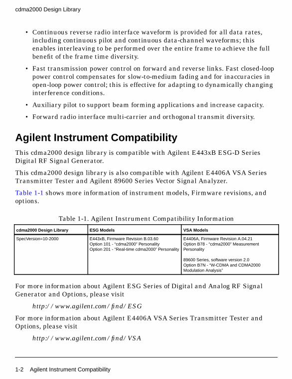
Agilent Instrument CompatibilityThis cdma2000 design library is compatible with Agilent E443xB ESG-D SeriesDigital RF Signal Generator.
This cdma2000 design library is also compatible with Agilent E4406A VSA SeriesTransmitter Tester and Agilent 89600 Series Vector Signal Analyzer.
Table 1-1 shows more information of instrument models, Firmware revisions, andoptions.
For more information about Agilent ESG Series of Digital and Analog RF SignalGenerator and Options, please visit
http://www.agilent.com/find/ESG
For more information about Agilent E4406A VSA Series Transmitter Tester andOptions, please visit
http://www.agilent.com/find/VSA
Table 1-1. Agilent Instrument Compatibility Information
cdma2000 Design Library ESG Models VSA Models
SpecVersion=10-2000 E443xB, Firmware Revision B.03.60Option 101 - “cdma2000” PersonalityOption 201 - “Real-time cdma2000” Personality
E4406A, Firmware Revision A.04.21Option B78 - “cdma2000” MeasurementPersonality
89600 Series, software version 2.0Option B7N - “W-CDMA and CDMA2000Modulation Analysis”
1-2 Agilent Instrument Compatibility
For more information about Agilent PSA Series Spectrum Analyzer and Options,please visit
http://www.agilent.com/find/PSA
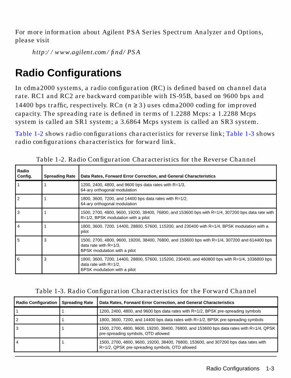
Radio ConfigurationsIn cdma2000 systems, a radio configuration (RC) is defined based on channel datarate. RC1 and RC2 are backward compatible with IS-95B, based on 9600 bps and14400 bps traffic, respectively. RCn ( ) uses cdma2000 coding for improvedcapacity. The spreading rate is defined in terms of 1.2288 Mcps: a 1.2288 Mcpssystem is called an SR1 system; a 3.6864 Mcps system is called an SR3 system.
Table 1-2 shows radio configurations characteristics for reverse link; Table 1-3 showsradio configurations characteristics for forward link.
Table 1-2. Radio Configuration Characteristics for the Reverse Channel
RadioConfig. Spreading Rate Data Rates, Forward Error Correction, and General Characteristics
1 1 1200, 2400, 4800, and 9600 bps data rates with R=1/3,64-ary orthogonal modulation
2 1 1800, 3600, 7200, and 14400 bps data rates with R=1/2,64-ary orthogonal modulation
3 1 1500, 2700, 4800, 9600, 19200, 38400, 76800, and 153600 bps with R=1/4, 307200 bps data rate withR=1/2, BPSK modulation with a pilot
4 1 1800, 3600, 7200, 14400, 28800, 57600, 115200, and 230400 with R=1/4, BPSK modulation with apilot
5 3 1500, 2700, 4800, 9600, 19200, 38400, 76800, and 153600 bps with R=1/4, 307200 and 614400 bpsdata rate with R=1/3,BPSK modulation with a pilot
6 3 1800, 3600, 7200, 14400, 28800, 57600, 115200, 230400, and 460800 bps with R=1/4, 1036800 bpsdata rate with R=1/2,BPSK modulation with a pilot
Table 1-3. Radio Configuration Characteristics for the Forward Channel
Radio Configuration Spreading Rate Data Rates, Forward Error Correction, and General Characteristics
1 1 1200, 2400, 4800, and 9600 bps data rates with R=1/2, BPSK pre-spreading symbols
2 1 1800, 3600, 7200, and 14400 bps data rates with R=1/2, BPSK pre-spreading symbols
3 1 1500, 2700, 4800, 9600, 19200, 38400, 76800, and 153600 bps data rates with R=1/4, QPSKpre-spreading symbols, OTD allowed
4 1 1500, 2700, 4800, 9600, 19200, 38400, 76800, 153600, and 307200 bps data rates withR=1/2, QPSK pre-spreading symbols, OTD allowed
n 3≥
Radio Configurations 1-3

cdma2000 Design Library
Channel StructuresThe assignment of the channels transmitted from a base station is shown inFigure 1-2; the assignment of the channels transmitted from a mobile station isshown in Figure 1-3. The use of each channel is described in the followingparagraphs.
Figure 1-2. Forward CDMA Channels Transmitted from a Base Station
5 1 1800, 3600, 7200, 14400, 28800, 57600, 115200, and 230400 bps data rates with R=1/4,QPSK pre-spreading symbols, OTD allowed
6 3 1500, 2700, 4800, 9600, 19200, 38400, 76800, 153600, and 307200 bps data rates withR=1/6, QPSK pre-spreading symbols, DS or MC modes, OTD allowed
7 3 1500, 2700, 4800, 9600, 19200, 38400, 76800, 153600, 307200, and 614400 bps data rateswith R=1/3, QPSK pre-spreading symbols, DS or MC modes, OTD allowed
8 3 1800, 3600, 7200, 14400, 28800, 57600, 115200, 230400, and 460800 bps data rates withR=1/4 or 1/3 (5 msec), QPSK pre-spreading symbols, DS or MC modes, OTD allowed
9 3 1800, 3600, 7200, 14400, 28800, 57600, 115200, 230400, 460800, and 1036800 bps datarates with R=1/2 or 1/3 (5 msec), QPSK pre-spreading symbols, DS or MC modes, OTDallowed
Table 1-3. Radio Configuration Characteristics for the Forward Channel (continued)
Radio Configuration Spreading Rate Data Rates, Forward Error Correction, and General Characteristics
1-4 Channel Structures
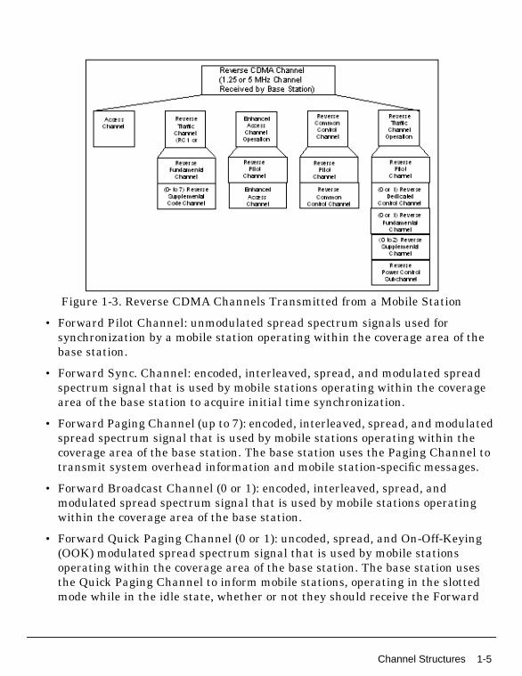
Figure 1-3. Reverse CDMA Channels Transmitted from a Mobile Station
• Forward Pilot Channel: unmodulated spread spectrum signals used forsynchronization by a mobile station operating within the coverage area of thebase station.
• Forward Sync. Channel: encoded, interleaved, spread, and modulated spreadspectrum signal that is used by mobile stations operating within the coveragearea of the base station to acquire initial time synchronization.
• Forward Paging Channel (up to 7): encoded, interleaved, spread, and modulatedspread spectrum signal that is used by mobile stations operating within thecoverage area of the base station. The base station uses the Paging Channel totransmit system overhead information and mobile station-specific messages.
• Forward Broadcast Channel (0 or 1): encoded, interleaved, spread, andmodulated spread spectrum signal that is used by mobile stations operatingwithin the coverage area of the base station.
• Forward Quick Paging Channel (0 or 1): uncoded, spread, and On-Off-Keying(OOK) modulated spread spectrum signal that is used by mobile stationsoperating within the coverage area of the base station. The base station usesthe Quick Paging Channel to inform mobile stations, operating in the slottedmode while in the idle state, whether or not they should receive the Forward
Channel Structures 1-5

cdma2000 Design Library
Common Control Channel or the Paging Channel starting in the next ForwardCommon Control Channel or Paging Channel slot.
• Forward Common Power Control Channel (0 or 1): used by the base station fortransmitting common power control subchannels (one bit per subchannel) forthe power control of multiple Reverse Common Control Channels andEnhanced Access Channels.
Forward Common Power Control Channel and Forward Common AssignmentChannel are optional for reducing the interference and collisions associatedwith system access.
• Forward Common Assignment Channel (0 or 1): designed to provide fastresponse reverse link channel assignments to support transmission of randomaccess packets on the reverse link. This channel controls the Reverse CommonControl Channel and the associated common power control subchannel in theReservation Mode and provides a fast acknowledgement in the PowerControlled Access Mode. It also implements congestion control.
Forward Common Power Control Channel and Forward Common AssignmentChannel are optional for reducing the interference and collisions associatedwith system access.
• Forward Common Control Channel (0 or more): encoded, interleaved, spread,and modulated spread spectrum signal that is used by mobile stationsoperating within the coverage area of the base station. The base station usesthe Forward Common Control Channel to transmit system overheadinformation and mobile station-specific messages.
• Forward Dedicated Control Channel (0 or more): transmission of user andsignaling information to a specific mobile station during a call. Each ForwardTraffic Channel may contain one Forward Dedicated Control Channel.
• Forward Traffic channels, each consisting of:
• Forward Fundamental Channel: transmission of user and signalinginformation to a specific mobile station during a call.
• Forward Supplemental Channel (0 to 7) for RC1 and RC2
• Forward Supplemental Channel (0 to 2) for RC3 through RC9: transmissionof user information to a specific mobile station during a call.
A traffic channel has at least one Forward Fundamental Channel; if high-speeddata is being sent, one or more Forward Supplemental Channels will be used. If
1-6 Channel Structures
the base station is sending RC1 or RC2 Forward Fundamental Channels, datais sent on one of seven Forward Supplemental Channels that are the same asIS-95B traffic channels. If the base station uses one of the new cdma2000 radioconfigurations (RC3-RC9), then one or two cdma2000 Forward SupplementalChannels are used.
• Reverse Pilot Channel (1): unmodulated spread spectrum signal used to assistthe base station in detecting a mobile station transmission. It also includespower control sub-channel when operating on the Reverse Traffic Channel withRC3 through RC6.
• Reverse Access or Enhanced Access Channel (1): used by the mobile station toinitiate communication with the base station and to respond to Paging Channelmessages.
• Reverse Common Control Channel (0 or 1): transmission of user and signalinginformation to the base station when Reverse Traffic Channels are not in use.
• Dedicated Control Channel (0 or 1): transmission of user and signalinginformation to the base station during a call.
• Reverse Fundamental Channel (0 or 1): for transmission of user and signaling.
• Reverse Supplemental Channel (0 to 2) for RC3 through RC6: for transmissionof user information to the base station during a call.
Overview of Component LibrariesThe cdma2000-Compliant Design Library of 128 behavioral models and subnetworksare organized in libraries that are described in the following sections.
Channel Components
Channel components provide multipath Rayleigh fading channel based on atapped-delay line model that is characterized by the number of taps, the time delayrelative to the first tap, the average power relative to the strongest tap, and theDoppler spectrum of each tap. They can be used in various test environments: indooroffice, outdoor to indoor and pedestrian, and vehicular.
Filters with flat and classic Doppler spectrum are provided. Doppler shift ismeasured according to mobile speed and carrier frequency. The input signal isdelayed according to the parameters given by ITU, then Doppler shift is applied.Signals on different paths are combined before being exported.
Overview of Component Libraries 1-7
cdma2000 Design Library
Channel Coding Components
Channel coding components provide frame generation and channel coding in thetransmit end, and channel decoding and frame recovery in the receiving end.
Convolutional code is applied in forward and reverse links to provide forward errorcorrection; turbo code is optional for high data rates.
Two types of convolutional encoders and Viterbi decoders are included: one for fixeddata rate signals with tail bits; one for variable data rate signals with tail bits. ForViterbi decoder, soft decision algorithm is used. Turbo encoders and decoders areprovided; the MAP algorithm is used in the turbo decoder.
The cdma2000 system uses several approaches to match data rates to Walsh spreaderinput rates. These include adjusting the code rate, using symbol repetition with orwithout symbol puncturing, and sequence repetition. A channel rate not equal to agiven channel data rate is realized by sequence repetition or by symbol repetitionwith symbol puncturing to match the desired channel data rate. Puncture andde-puncture, framing and de-framing, rate matching and rate dematching areprovided. Rate detector is included.
Interleavers and de-interleavers are provided for all types of channels and radioconfigurations, turbo encoder and decoder.
Receiver Components
Receiver components provide channel estimation, maximal ratio combination, andautomatic frequency control for forward link and reverse link.
• Channel estimation components for forward and reverse links search thestrongest paths, with their strengths and delays estimated.
• In coherent receivers, coherent demodulation and despreading are performedand maximal ratio combination is carried out using the channel coefficientsderived from channel estimator.
• An automatic frequency control loop that consists of phase detector, LPF andNCO, is used to recover carrier frequency.
RF Subsystem Components
RF subsystem components include RF modulation and demodulation.
1-8 Overview of Component Libraries
• CDMA2K_RF_Mod provides RF modulation. Input signals are used tomodulate in-phase and quadrature-phase carriers of a QAM modulator.
• CDMA2K_RF_Demod provides RF demodulation. Output signals are thebaseband I and Q components of the RF input signal.
Signal Source Components
Signal source components include different radio configurations and data rates offorward and reverse link signals.
• CDMA2K_FwdRCsrc and CDMA2K_RevRCsrc provide forward and reverselink signal sources of different radio configurations and data rates.
• CDMA2K_FwdOTDsrc and CDMA2K_FwdSTSsrc provide forward linkorthogonal transmit diversity and space time spread signal sources of differentradio configurations and data rates.
• CDMA2K_FwdPilotSrc produces the forward pilot signal.
Transmission Components
Transmission components provide modulation, code generation and spreading,transmission power adjustment, and signal shaping.
• CDMA2K_FwdQPSK performs forward channel QPSK modulation. Data of Iand Q channels are complex multiplied against a pair of I and Q channel shortPN codes.
• CDMA2K_RevHPSK performs reverse channel hybrid PSK modulation.
• CDMA2K_LongCodeGenerator and CDMA2K_SR3LongCode generate longcodes for SR1 and SR3, respectively.
• CDMA2K_VL_Walsh generates variable length Walsh code;CDMA2K_WalshModulator spreads input data by Walsh code.
• CDMA2K_FwdPowerAllocation and CDMA2K_RevPowerAllocation allocatepower for different channels on forward link and reverse link, respectively.
• CDMA2K_FwdSIREstimate and CDMA2K_RevSIREstimate estimate SIR forforward and reverse link, respectively, when power control is performed.
Overview of Component Libraries 1-9
cdma2000 Design Library
• CDMA2K_FIR and CDMA2K_BaseFilter are pulse-shaping filters on thetransmit end or matched filters on the receiving end with floating-point andcomplex inputs, respectively.
• CDMA2K_PowerControl generates power control bits for forward or reverselink.
Test Components
Test includes auxiliary models such as BER and FER measurement, powermeasurement, code domain power and Rho measurement, and signal source ofmultiple users.
• CDMA2K_BFER compares values of two inputs and then calculates BER andFER.
• CDMA2K_PowerMeasure measures the average power of the input signal.
• CDMA2K_FwdMultiUserSrc provides signal source of multiple users onforward link.
• CDMA2K_CDP measures code domain power.
• CDMA2K_FwdRho and CDMA2K_RevRhoWithRef measure forward andreverse link waveform quality (Rho).
Overview of Example DesignsExample designs are provided with the cdma2000-Compliant Design Library, in the/examples/cdma2k directory. Projects and their corresponding design examples arelisted here.
CDMA2K_BER_prj
• DsnCDMA2K_FwdRC3AWGN.dsn
• DsnCDMA2K_RevRC3AWGN.dsn
CDMA2K_Measurement_prj
• DsnCDMA2K_FwdSR1Trans.dsn
• DsnCDMA2K_FwdSR3Trans.dsn
• DsnCDMA2K_H_Q_PSK_PAPR.dsn
1-10 Overview of Example Designs
• DsnCDMA2K_RevSR1Hpsk.dsn
• DsnCDMA2K_RevSR3Hpsk.dsn
CDMA2K_Rake_prj
• DsnCDMA2K_FwdRake.dsn
• DsnCDMA2K_RevRake.dsn
CDMA2K_RC_TD_prj
• DsnCDMA2K_MCRC8.dsn
• DsnCDMA2K_FwdRC6AWGN.dsn
• DsnCDMA2K_FwdRC3OTD.dsn
• DsnCDMA2K_FwdRC3DS.dsn
• DsnCDMA2K_FwdRC3AWGN.dsn
• DsnCDMA2K_RevRC6AWGN.dsn
• DsnCDMA2K_RevRC3AWGN.dsn
• DsnCDMA2K_RevRC3Fade.dsn
CDMA2K_TPC_prj
• DsnCDMA2K_FwdPC.dsn
• DsnCDMA2K_RevPC.dsn
CDMA2K_TurboCode_prj
• DsnCDMA2K_TurboCode.dsn
BS_RX_prj
• BS_RxAdjacentSelectivityRC3.dsn
• BS_RxDemodRC4AWGN.dsn
• BS_RxDnmcRngRC3.dsn
• BS_RxIntermodulationRC3.dsn
• BS_RxSingleToneRC3.dsn
• BS_RxTxLeakageRC3.dsn
BS_TX_prj
Overview of Example Designs 1-11

cdma2000 Design Library
• BS_TxCDP_RC3.dsn
• BS_TxCDP_RC3OTD.dsn
• BS_TxMeanPower.dsn
• BS_TxPilotPower.dsn
• BS_TxRho.dsn
• BS_TxSR1Spectrum.dsn
MS_RX_prj
• MS_RxAdjacentSelectivityRC3.dsn
• MS_RxDemodRC4AWGN.dsn
• MS_RxDnmcRngRC3.dsn
• MS_RxIntermodulationRC3.dsn
• MS_RxSingleToneRC3.dsn
• MS_RxTxLeakageRC3.dsn
MS_TX_prj
• MS_TxCDP_RC3.dsn
• MS_TxMeanPowerSR1.dsn
• MS_TxPowerAccuracyRC3.dsn
• MS_TxRhoRC3.dsn
• MS_TxSR1Spectrum.dsn
SignalSource_prj
• BS_PilotSrc.dsn
• BS_SR1Src.dsn
• MS_SR1Src.dsn
1-12 Overview of Example Designs

Glossary of Terms
Table 1-4. Glossary of TermsAFC automatic frequency control
AWGN additive white Gaussian noise
BER bit error rate
bps bits per second
BPSK binary phase shift keying
BS base station
CC convolutional code
CCDF complementary cumulative distribution function
CDMA code division multiple access
CRC cyclic redundancy code
DS direct spread
FER frame error rate
HPSK hybrid phase shift keying
MAP maximum a posteriori
MC multi-carrier
MS mobile station
NRZ non-return-to-zero
OTD orthogonal transmit diversity
PN code pseudo noise sequence
QPSK quadrature phase shift keying
RC radio configuration
SIR signal-to-interference ratio
SNR signal-to-noise ratio
SR spread rate
STS space time spread
TPC transmit power control
Glossary of Terms 1-13

cdma2000 Design Library
1-14 Glossary of Terms

Chapter 2: Channel Components
2-1

Channel Components
CDMA2K_ClassicChannel
Description Multi-Path Fading Channel with Classic SpectrumLibrary cdma2000, Channel
Parameters
Name Description Default Unit Type Range
SamplingRate sampling rate 4915200 real (0, ∞)
Dpath2 time delay of second taprelative to the first tap
310n sec real (0, ∞)
Dpath3 time delay of third taprelative to the first tap
710n sec real (0, ∞)
Dpath4 time delay of fourth taprelative to the first tap
1090n sec real (0, ∞)
Dpath5 time delay of fifth taprelative to the first tap
1730n sec real (0, ∞)
Dpath6 time delay of sixth taprelative to the first tap
2510n sec real (0, ∞)
Gpath1_dB average power of first taprelative to the strongest tapin dB
0 real (∞, 0]
Gpath2_dB average power of secondtap relative to the strongesttap in dB
-1.0 real (∞, 0]
Gpath3_dB average power of third taprelative to the strongest tapin dB
-9.0 real (∞, 0]
Gpath4_dB average power of fourth taprelative to the strongest tapin dB
-10.0 real (∞, 0]
Gpath5_dB average power of fifth taprelative to the strongest tapin dB
-15.0 real (∞, 0]
Gpath6_dB average power of sixth taprelative to the strongest tapin dB
-20.0 real (∞, 0]
2-2

Pin Inputs
Pin Outputs
Notes/Equations
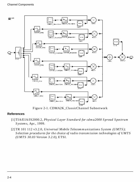
1. This subnetwork is used to pass the input signal through a multipath Rayleighfading channel based on a tapped-delay line model. The Doppler spectrum isclassic. The maximum number of paths is 6. If Gpathi_dB(i=1, 2, ... , 6) is set tolarger than 0, then this tap is ignored. There is no path loss in this model.
Figure 2-1 shows the schematic for this subnetwork.
Velocity velocity of mobilestation,km/hour
120 real [0, 5000)
CarrierFrequency carrier frequency 825M Hz real (0, ∞)
Pin Name Description Signal Type
1 SigIn input signal complex
Pin Name Description Signal Type
2 SigOut output signal after passing channel complex
Name Description Default Unit Type Range
2-3
Channel Components
Figure 2-1. CDMA2K_ClassicChannel Subnetwork
References
[1]TIA/EIA/IS2000.2, Physical Layer Standard for cdma2000 Spread SpectrumSystems, Apr., 1999.
[2] TR 101 112 v3.2.0, Universal Mobile Telecommunications System (UMTS);Selection procedures for the choice of radio transmission technologies of UMTS(UMTS 30.03 Version 3.2.0), ETSI.
2-4
CDMA2K_ClassicSpec
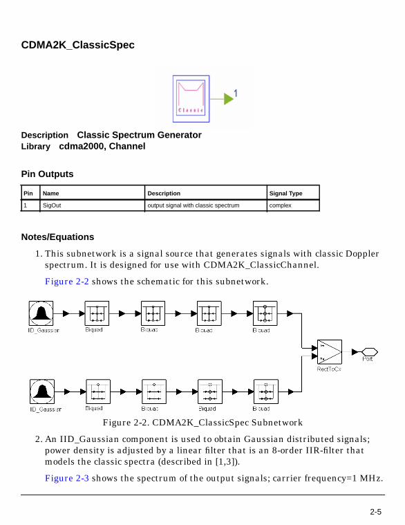
Description Classic Spectrum GeneratorLibrary cdma2000, Channel
Pin Outputs
Notes/Equations
1. This subnetwork is a signal source that generates signals with classic Dopplerspectrum. It is designed for use with CDMA2K_ClassicChannel.
Figure 2-2 shows the schematic for this subnetwork.
Figure 2-2. CDMA2K_ClassicSpec Subnetwork
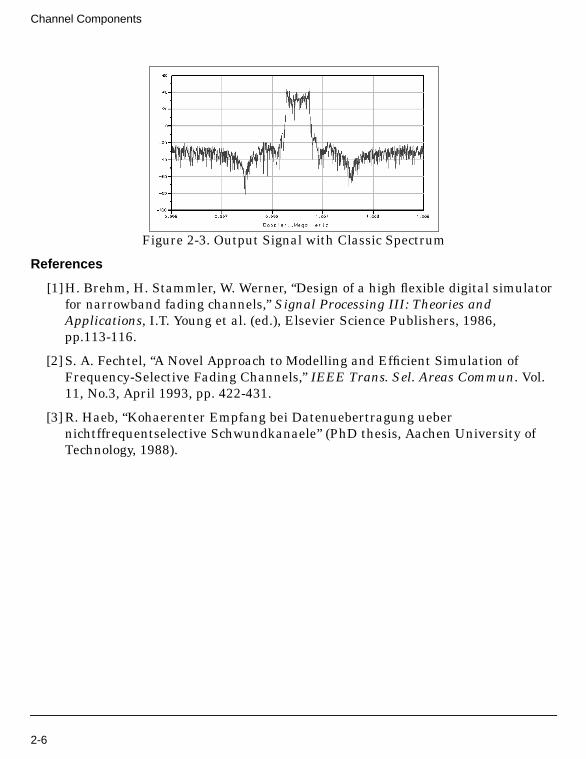
2. An IID_Gaussian component is used to obtain Gaussian distributed signals;power density is adjusted by a linear filter that is an 8-order IIR-filter thatmodels the classic spectra (described in [1,3]).
Figure 2-3 shows the spectrum of the output signals; carrier frequency=1 MHz.
Pin Name Description Signal Type
1 SigOut output signal with classic spectrum complex
2-5
Channel Components
Figure 2-3. Output Signal with Classic Spectrum
References
[1]H. Brehm, H. Stammler, W. Werner, “Design of a high flexible digital simulatorfor narrowband fading channels,” Signal Processing III: Theories andApplications, I.T. Young et al. (ed.), Elsevier Science Publishers, 1986,pp.113-116.
[2] S. A. Fechtel, “A Novel Approach to Modelling and Efficient Simulation ofFrequency-Selective Fading Channels,” IEEE Trans. Sel. Areas Commun. Vol.11, No.3, April 1993, pp. 422-431.
[3] R. Haeb, “Kohaerenter Empfang bei Datenuebertragung uebernichtffrequentselective Schwundkanaele” (PhD thesis, Aachen University ofTechnology, 1988).
2-6

CDMA2K_Delay
Description Signal delay based on channel tapped-delay line modelLibrary cdma2000, ChannelClass SDFCDMA2K_Delay
Parameters
Pin Inputs
Pin Outputs
Notes/Equations
1. This model is used to delay the input signal by the time specified by Delay. It isused in channel impulse response model based on a tapped-delay line model.
Each firing, Max(64, int(fsτ)+1) SigOut tokens are produced whenMax(64, int(fsτ)+1) SigIn tokens are consumed.
References
[1]TIA/EIA/IS2000.2, Physical Layer Standard for cdma2000 Spread SpectrumSystems, Apr., 1999.
Name Description Default Sym Unit Type Range
SamplingRate sampling rate 4915200 fs int [1, ∞)
Delay delay time 50n τ sec real (-∞, ∞)
Pin Name Description Signal Type
1 SigIn input signals complex
Pin Name Description Signal Type
2 SigOut output signals after delay complex
2-7

Channel Components
[2] J. G. Proakis, Digital Communications, Third Edition, Publishing House ofElectronics Industry.
2-8
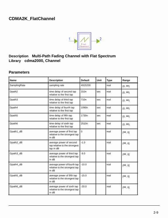
CDMA2K_FlatChannel
Description Multi-Path Fading Channel with Flat SpectrumLibrary cdma2000, Channel
Parameters
Name Description Default Unit Type Range
SamplingRate sampling rate 4915200 real (0, ∞)
Dpath2 time delay of second taprelative to the first tap
310n sec real (0, ∞)
Dpath3 time delay of third taprelative to the first tap
710n sec real (0, ∞)
Dpath4 time delay of fourth taprelative to the first tap
1090n sec real (0, ∞)
Dpath5 time delay of fifth taprelative to the first tap
1730n sec real (0, ∞)
Dpath6 time delay of sixth taprelative to the first tap
2510n sec real (0, ∞)
Gpath1_dB average power of first taprelative to the strongest tapin dB
0 real (∞, 0]
Gpath2_dB average power of secondtap relative to the strongesttap in dB
-1.0 real (∞, 0]
Gpath3_dB average power of third taprelative to the strongest tapin dB
-9.0 real (∞, 0]
Gpath4_dB average power of fourth taprelative to the strongest tapin dB
-10.0 real (∞, 0]
Gpath5_dB average power of fifth taprelative to the strongest tapin dB
-15.0 real (∞, 0]
Gpath6_dB average power of sixth taprelative to the strongest tapin dB
-20.0 real (∞, 0]
2-9
Channel Components
Pin Inputs
Pin Outputs
Notes/Equations
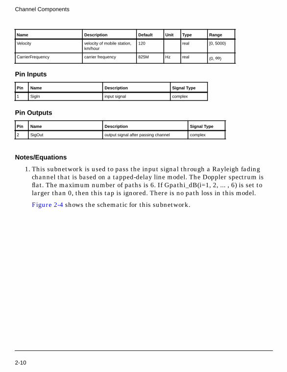
1. This subnetwork is used to pass the input signal through a Rayleigh fadingchannel that is based on a tapped-delay line model. The Doppler spectrum isflat. The maximum number of paths is 6. If Gpathi_dB(i=1, 2, ... , 6) is set tolarger than 0, then this tap is ignored. There is no path loss in this model.
Figure 2-4 shows the schematic for this subnetwork.
Velocity velocity of mobile station,km/hour
120 real [0, 5000)
CarrierFrequency carrier frequency 825M Hz real (0, ∞)
Pin Name Description Signal Type
1 SigIn input signal complex
Pin Name Description Signal Type
2 SigOut output signal after passing channel complex
Name Description Default Unit Type Range
2-10
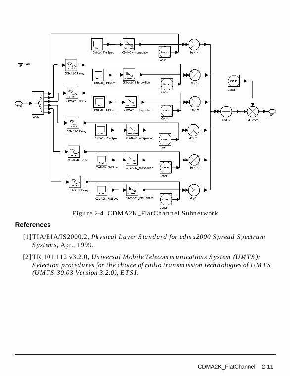
Figure 2-4. CDMA2K_FlatChannel Subnetwork
References
[1]TIA/EIA/IS2000.2, Physical Layer Standard for cdma2000 Spread SpectrumSystems, Apr., 1999.
[2] TR 101 112 v3.2.0, Universal Mobile Telecommunications System (UMTS);Selection procedures for the choice of radio transmission technologies of UMTS(UMTS 30.03 Version 3.2.0), ETSI.
CDMA2K_FlatChannel 2-11
Channel Components
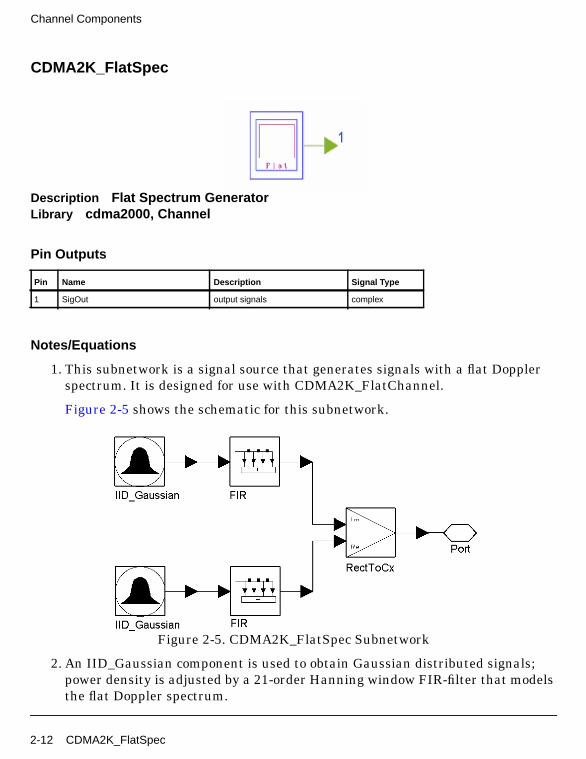
CDMA2K_FlatSpec
Description Flat Spectrum GeneratorLibrary cdma2000, Channel
Pin Outputs
Notes/Equations
1. This subnetwork is a signal source that generates signals with a flat Dopplerspectrum. It is designed for use with CDMA2K_FlatChannel.
Figure 2-5 shows the schematic for this subnetwork.
Figure 2-5. CDMA2K_FlatSpec Subnetwork
2. An IID_Gaussian component is used to obtain Gaussian distributed signals;power density is adjusted by a 21-order Hanning window FIR-filter that modelsthe flat Doppler spectrum.
Pin Name Description Signal Type
1 SigOut output signals complex
2-12 CDMA2K_FlatSpec

Figure 2-6 shows the output signal; carrier frequency=1MHz.
Figure 2-6. Output Signal Spectrum
References
[1]H. Brehm, H. Stammler, W. Werner, “Design of a high flexible digital simulatorfor narrowband fading channels,” Signal Processing III: Theories andApplications, I.T. Young et al. (ed.), Elsevier Science Publishers, 1986,pp.113-116.
[2] S. A. Fechtel, “A Novel Approach to Modelling and Efficient Simulation ofFrequency-Selective Fading Channels,” IEEE Trans. Sel. Areas Commun., Vol.11, No.3, April 1993, pp. 422-431.
[3] H. Zhenya, Theories and Applications of Digital Signal Processing, Publishedby postal publishing company of Chinese, 1987.
CDMA2K_FlatSpec 2-13
Channel Components
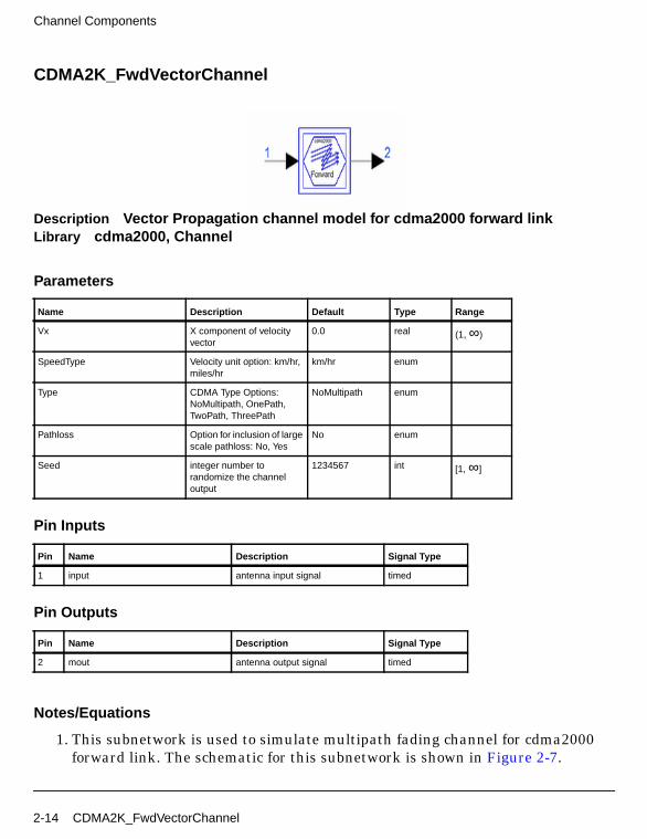
CDMA2K_FwdVectorChannel
Description Vector Propagation channel model for cdma2000 forward linkLibrary cdma2000, Channel
Parameters
Pin Inputs
Pin Outputs
Notes/Equations
1. This subnetwork is used to simulate multipath fading channel for cdma2000forward link. The schematic for this subnetwork is shown in Figure 2-7.
Name Description Default Type Range
Vx X component of velocityvector
0.0 real (1, ∞)
SpeedType Velocity unit option: km/hr,miles/hr
km/hr enum
Type CDMA Type Options:NoMultipath, OnePath,TwoPath, ThreePath
NoMultipath enum
Pathloss Option for inclusion of largescale pathloss: No, Yes
No enum
Seed integer number torandomize the channeloutput
1234567 int [1, ∞]
Pin Name Description Signal Type
1 input antenna input signal timed
Pin Name Description Signal Type
2 mout antenna output signal timed
2-14 CDMA2K_FwdVectorChannel
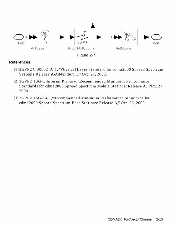
Figure 2-7.
References
[1]3GPP2 C.S0002_A_1, “Physical Layer Standard for cdma2000 Spread SpectrumSystems Release A-Addendum 1,” Oct. 27, 2000.
[2] 3GPP2 TSG-C Interim Plenary, “Recommended Minimum PerformanceStandards for cdma2000 Spread Spectrum Mobile Stations: Release A,” Nov. 27,2000.
[3] 3GPP2 TSG-C4.1,“Recommended Minimum Performance Standards forcdma2000 Spread Spectrum Base Stations: Release A,” Oct. 26, 2000.
CDMA2K_FwdVectorChannel 2-15
Channel Components
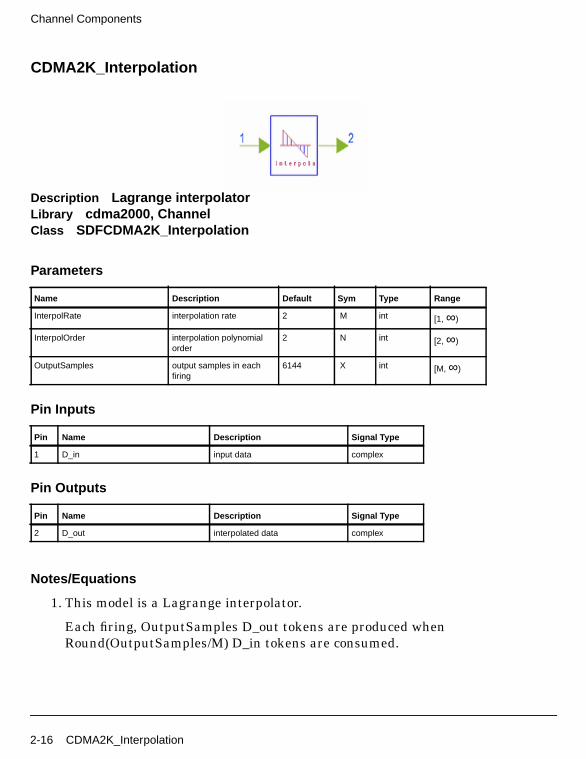
CDMA2K_Interpolation
Description Lagrange interpolatorLibrary cdma2000, ChannelClass SDFCDMA2K_Interpolation
Parameters
Pin Inputs
Pin Outputs
Notes/Equations
1. This model is a Lagrange interpolator.
Each firing, OutputSamples D_out tokens are produced whenRound(OutputSamples/M) D_in tokens are consumed.
Name Description Default Sym Type Range
InterpolRate interpolation rate 2 M int [1, ∞)
InterpolOrder interpolation polynomialorder
2 N int [2, ∞)
OutputSamples output samples in eachfiring
6144 X int [M, ∞)
Pin Name Description Signal Type
1 D_in input data complex
Pin Name Description Signal Type
2 D_out interpolated data complex
2-16 CDMA2K_Interpolation

CDMA2K_RevVectorChannel
Description Vector Propagation channel model for cdma2000 reverse linkLibrary cdma2000, Channel
Parameters
Pin Inputs
Pin Outputs
Notes/Equations
1. This subnetwork is used to simulate multipath fading channel for cdma2000reverse link. The schematic for this subnetwork is shown in Figure 2-8.
Name Description Default Type Range
Vx X component of velocityvector
0.0 real (0, ∞)
SpeedType Velocity unit option: km/hr,miles/hr
km/hr enum
Type CDMA Type Options:NoMultipath, OnePath,TwoPath, ThreePath
NoMultipath enum
Pathloss Option for inclusion of largescale pathloss: No, Yes
No enum
Seed integer number torandomize the channeloutput
1234567 int [1, 65535
Pin Name Description Signal Type
1 input antenna input signal timed
Pin Name Description Signal Type
2 mout antenna output signal timed
CDMA2K_RevVectorChannel 2-17

Channel Components
Figure 2-8. CDMA2K_RevVectorChannel Subnetwork
References
[1]3GPP2 C.S0002_A_1, “Physical Layer Standard for cdma2000 Spread SpectrumSystems Release A-Addendum 1,” Oct. 27, 2000.
[2] 3GPP2 TSG-C Interim Plenary, “Recommended Minimum PerformanceStandards for cdma2000 Spread Spectrum Mobile Stations: Release A,” Nov. 27,2000.
[3] 3GPP2 TSG-C4.1,“Recommended Minimum Performance Standards forcdma2000 Spread Spectrum Base Stations: Release A,” Oct. 26, 2000.
2-18 CDMA2K_RevVectorChannel

Chapter 3: Channel Coding Components
3-1
Channel Coding Components
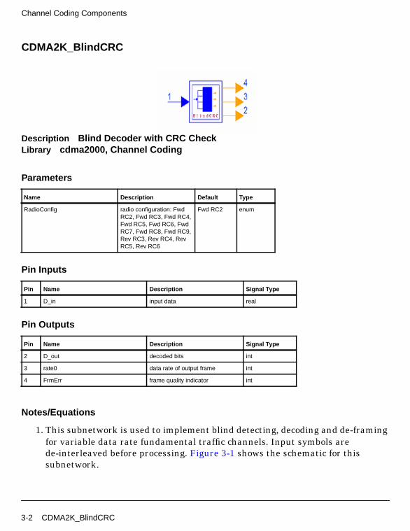
CDMA2K_BlindCRC
Description Blind Decoder with CRC CheckLibrary cdma2000, Channel Coding
Parameters
Pin Inputs
Pin Outputs
Notes/Equations
1. This subnetwork is used to implement blind detecting, decoding and de-framingfor variable data rate fundamental traffic channels. Input symbols arede-interleaved before processing. Figure 3-1 shows the schematic for thissubnetwork.
Name Description Default Type
RadioConfig radio configuration: FwdRC2, Fwd RC3, Fwd RC4,Fwd RC5, Fwd RC6, FwdRC7, Fwd RC8, Fwd RC9,Rev RC3, Rev RC4, RevRC5, Rev RC6
Fwd RC2 enum
Pin Name Description Signal Type
1 D_in input data real
Pin Name Description Signal Type
2 D_out decoded bits int
3 rate0 data rate of output frame int
4 FrmErr frame quality indicator int
3-2 CDMA2K_BlindCRC
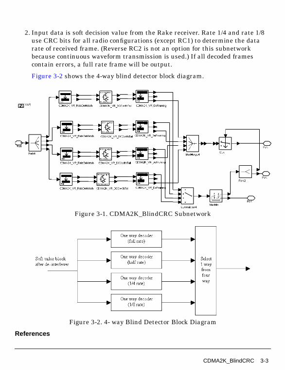
2. Input data is soft decision value from the Rake receiver. Rate 1/4 and rate 1/8use CRC bits for all radio configurations (except RC1) to determine the datarate of received frame. (Reverse RC2 is not an option for this subnetworkbecause continuous waveform transmission is used.) If all decoded framescontain errors, a full rate frame will be output.
Figure 3-2 shows the 4-way blind detector block diagram.
Figure 3-1. CDMA2K_BlindCRC Subnetwork
Figure 3-2. 4- way Blind Detector Block Diagram
References
CDMA2K_BlindCRC 3-3
Channel Coding Components
[1]TIA/EIA/IS-2000.2 (PN-4428), Physical Layer Standard for cdma2000 SpreadSpectrum Systems, July, 1999.
3-4 CDMA2K_BlindCRC

CDMA2K_BlindDecoder
Description Blind Decoder with BER ComparisonLibrary cdma2000, Channel Coding
Parameters
Pin Inputs
Pin Outputs
Notes/Equations
1. This subnetwork is used to implement blind detecting, decoding, andde-framing for data rates in fundamental channels. The input symbols arede-interleaved before processing.
Figure 3-3 shows the schematic for this subnetwork.
Name Description Default Type
RadioConfig radio configuration: FwdRC1, Fwd RC2, Fwd RC3,Fwd RC4, Fwd RC5, FwdRC6, Fwd RC7, Fwd RC8,Fwd RC9, Rev RC3, RevRC4, Rev RC5, Rev RC6
Fwd RC1 enum
Pin Name Description Signal Type
1 D_in input data real
Pin Name Description Signal Type
2 D_out decoded bits int
3 rate0 data rate of output frame int
4 FrmErr frame quality indicator int
CDMA2K_BlindDecoder 3-5

Channel Coding Components
2. Input data is from the Viterbi decoder with soft decision. In one-way decoder,decoding is performed according to data rate and the BER of this output frameis measured. The date rate with minimum BER is used as the transmit datarate; the frame with minimum BER is output.
Figure 3-4 shows the 4-way blind detector block diagram.
Figure 3-3. CDMA2K_BlindDecoder Subnetwork
Figure 3-4. 4-Way Blind Detector Block Diagram
References
3-6 CDMA2K_BlindDecoder
[1]TIA/EIA/IS-2000.2 (PN-4428), Physical Layer Standard for cdma2000 SpreadSpectrum Systems, July, 1999.
CDMA2K_BlindDecoder 3-7
Channel Coding Components
CDMA2K_BlindRevRC1_2
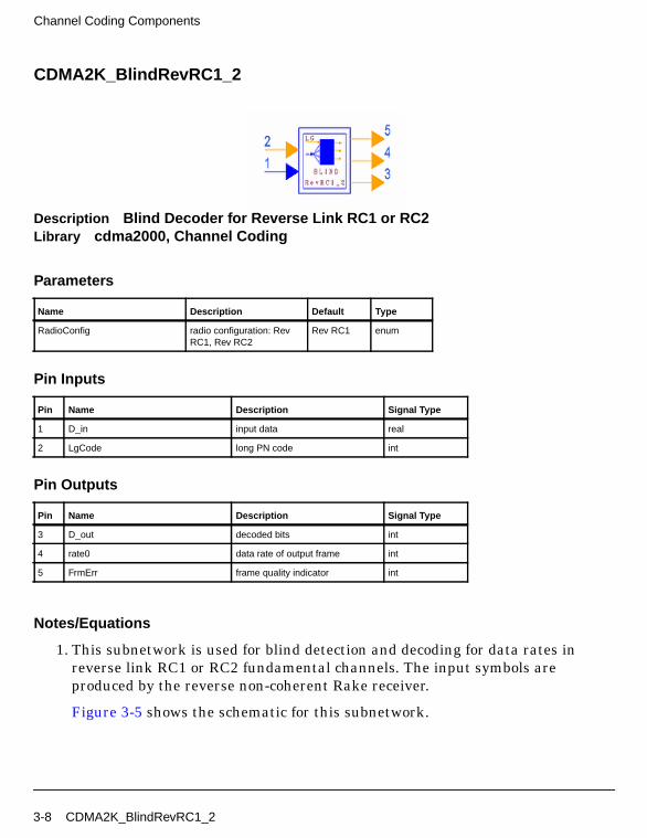
Description Blind Decoder for Reverse Link RC1 or RC2Library cdma2000, Channel Coding
Parameters
Pin Inputs
Pin Outputs
Notes/Equations
1. This subnetwork is used for blind detection and decoding for data rates inreverse link RC1 or RC2 fundamental channels. The input symbols areproduced by the reverse non-coherent Rake receiver.
Figure 3-5 shows the schematic for this subnetwork.
Name Description Default Type
RadioConfig radio configuration: RevRC1, Rev RC2
Rev RC1 enum
Pin Name Description Signal Type
1 D_in input data real
2 LgCode long PN code int
Pin Name Description Signal Type
3 D_out decoded bits int
4 rate0 data rate of output frame int
5 FrmErr frame quality indicator int
3-8 CDMA2K_BlindRevRC1_2
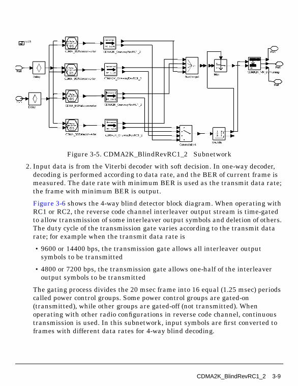
Figure 3-5. CDMA2K_BlindRevRC1_2 Subnetwork
2. Input data is from the Viterbi decoder with soft decision. In one-way decoder,decoding is performed according to data rate, and the BER of current frame ismeasured. The date rate with minimum BER is used as the transmit data rate;the frame with minimum BER is output.
Figure 3-6 shows the 4-way blind detector block diagram. When operating withRC1 or RC2, the reverse code channel interleaver output stream is time-gatedto allow transmission of some interleaver output symbols and deletion of others.The duty cycle of the transmission gate varies according to the transmit datarate; for example when the transmit data rate is
• 9600 or 14400 bps, the transmission gate allows all interleaver outputsymbols to be transmitted
• 4800 or 7200 bps, the transmission gate allows one-half of the interleaveroutput symbols to be transmitted
The gating process divides the 20 msec frame into 16 equal (1.25 msec) periodscalled power control groups. Some power control groups are gated-on(transmitted), while other groups are gated-off (not transmitted). Whenoperating with other radio configurations in reverse code channel, continuoustransmission is used. In this subnetwork, input symbols are first converted toframes with different data rates for 4-way blind decoding.
CDMA2K_BlindRevRC1_2 3-9

Channel Coding Components
Figure 3-6. 4-Way Blind Detector Block Diagram
References
[1]TIA/EIA/IS-2000.2 (PN-4428), Physical Layer Standard for cdma2000 SpreadSpectrum Systems, July 1999.
3-10 CDMA2K_BlindRevRC1_2
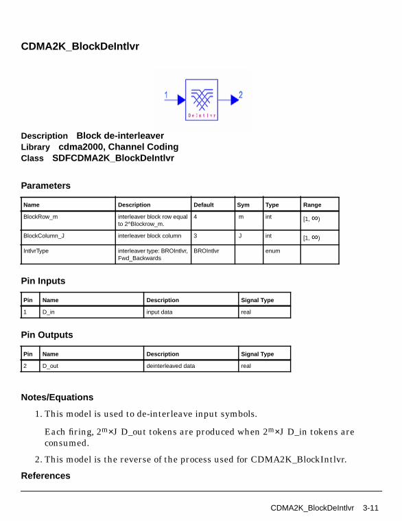
CDMA2K_BlockDeIntlvr
Description Block de-interleaverLibrary cdma2000, Channel CodingClass SDFCDMA2K_BlockDeIntlvr
Parameters
Pin Inputs
Pin Outputs
Notes/Equations
1. This model is used to de-interleave input symbols.
Each firing, 2m×J D_out tokens are produced when 2m×J D_in tokens areconsumed.
2. This model is the reverse of the process used for CDMA2K_BlockIntlvr.
References
Name Description Default Sym Type Range
BlockRow_m interleaver block row equalto 2^Blockrow_m.
4 m int [1, ∞)
BlockColumn_J interleaver block column 3 J int [1, ∞)
IntlvrType interleaver type: BROIntlvr,Fwd_Backwards
BROIntlvr enum
Pin Name Description Signal Type
1 D_in input data real
Pin Name Description Signal Type
2 D_out deinterleaved data real
CDMA2K_BlockDeIntlvr 3-11

Channel Coding Components
[1]TIA/EIA/IS-2000.2 (PN-4428), Physical Layer Standard for cdma2000 SpreadSpectrum Systems, July 1999.
3-12 CDMA2K_BlockDeIntlvr

CDMA2K_BlockIntlvr
Description Block interleaverLibrary cdma2000, Channel CodingClass SDFCDMA2K_BlockIntlvr
Parameters
Pin Inputs
Pin Outputs
Notes/Equations
1. This model is used to interleave the input symbols.
Each firing, 2m×J D_out tokens are produced when 2m×J D_in tokens areconsumed.
2. Interleavers used in this model are described in the following paragraphs.
BRO Interleaver
Name Description Default Sym Type Range
BlockRow_m interleaver block row equalto 2^Blockrow_m.
4 m int [1, ∞)
BlockColumn_J interleaver block column 3 J int [1, ∞)
IntlvrType interleaver type: BROIntlvr,Fwd_Backwards
BROIntlvr enum
Pin Name Description Signal Type
1 D_in input data real
Pin Name Description Signal Type
2 D_out output interleaved data real
CDMA2K_BlockIntlvr 3-13
Channel Coding Components
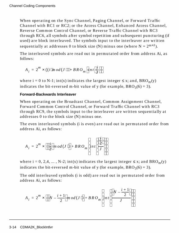
When operating on the Sync Channel, Paging Channel, or Forward TrafficChannel with RC1 or RC2; or the Access Channel, Enhanced Access Channel,Reverse Common Control Channel, or Reverse Traffic Channel with RC3through RC6, all symbols after symbol repetition and subsequent puncturing (ifused) are block interleaved. The symbols input to the interleaver are writtensequentially at addresses 0 to block size (N) minus one (where N = 2m×J).
The interleaved symbols are read out in permutated order from address Ai, asfollows:
where i = 0 to N-1; int(x) indicates the largest integer ≤ x; and, BROm(y)indicates the bit-reversed m-bit value of y (for example, BRO3(6) = 3).
Forward-Backwards Interleaver
When operating on the Broadcast Channel, Common Assignment Channel,Forward Common Control Channel, or Forward Traffic Channel with RC3through RC9, the symbols input to the interleaver are written sequentially ataddresses 0 to the block size (N) minus one.
The even interleaved symbols (i is even) are read out in permutated order fromaddress Ai, as follows:
where i = 0, 2,4, ... , N-2; int(x) indicates the largest integer ≤ x; and BROm(y)indicates the bit-reversed m-bit value of y (for example, BRO3(6) = 3).
The odd interleaved symbols (i is odd) are read out in permutated order fromaddress Ai, as follows:
Ai 2m i( )mod J( )( )× BROm int i
J---
+=
Ai 2m i
2---
mod J( ) × BROm int
i2---
J--------
+=
Ai 2m N i 1+
2-----------–
mod J( ) × BROm int
N i 1+2
-----------–
J----------------------------
+=
3-14 CDMA2K_BlockIntlvr

where i = 1,3, ... , N-1; int(x) indicates the largest integer ≤ x; and BROm(y)indicates the bit-reversed m-bit value of y (for example, BRO3(6) = 3).
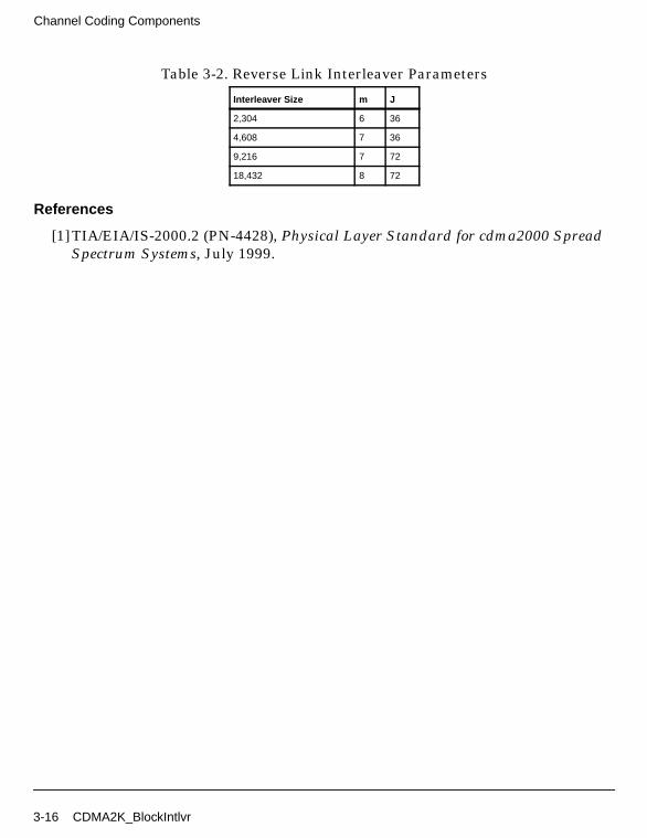
Forward link interleaver parameters m and J are given in Table 3-1; reverselink interleaver parameters m and J are given in Table 3-2.
Table 3-1. Forward Link Interleaver Parameters
Interleaver Size m J
48 4 3
96 5 3
192 6 3
384 6 6
768 6 12
1,536 6 24
3,072 6 48
6,144 7 48
12,288 7 96
144 4 9
288 5 9
576 5 18
1,152 6 18
2,304 6 36
4,608 7 36
9,216 7 72
18,432 8 72
36,864 8 144
128 7 1
Table 3-2. Reverse Link Interleaver Parameters
Interleaver Size m J
384 6 6
768 6 12
1,536 6 24
3,072 6 48
6,144 7 48
12,288 7 96
576 5 18
CDMA2K_BlockIntlvr 3-15
Channel Coding Components
References
[1]TIA/EIA/IS-2000.2 (PN-4428), Physical Layer Standard for cdma2000 SpreadSpectrum Systems, July 1999.
2,304 6 36
4,608 7 36
9,216 7 72
18,432 8 72
Table 3-2. Reverse Link Interleaver Parameters
Interleaver Size m J
3-16 CDMA2K_BlockIntlvr

CDMA2K_CC_WithTail
Description Convolutional encoder with tailLibrary cdma2000, Channel CodingClass SDFCDMA2K_CC_WithTailDerived From CDMA2K_CnvlCoder
Parameters
Pin Inputs
Name Description Default Type Range
ModeSelect mode for settingparameters: ChooseCCType from list, Userdefined
Choose CCTypefrom list
enum
CCType convolutional code type;used whenModeSelect=ChooseCCType from list: rate 1/2K 9 g0 0753 g1 0561, rate1/3 K 9 g0 0557 g1 0663g2 0711, rate 1/4 K 9 g00765 g1 0671 g2 0513 g30473, rate 1/6 K 9 g0 0457g1 0755 g2 0551 g3 0637g4 0625 g5_0727
rate 1/2 K 9 g00753 g1 0561
enum
ConstraintLength constraint length ofconvolutional code; usewhen ModeSelect=Userdefined
9 int
Polynomial generator polynomial 0753 0561 int array
InputFrameLen input frame length 96 int [K, ∞)
Pin Name Description Signal Type
1 D_in input data with enough tail bits int
CDMA2K_CC_WithTail 3-17

Channel Coding Components
Pin Outputs
Notes/Equations
1. This model is used to convolutional encode frame by frame; each frame musthave at least K-1 tail bits.
Each firing, if ModeSelect is
• Choose CCType from list, 1/rate (specified by CCType)×InputFrameLenoutput tokens are produced when InputFrameLen input tokens areconsumed.
• User defined, user input N generator functions, N×InputFrameLen outputtokens are produced when InputFrameLen input tokens are consumed.
References
[1]TIA/EIA/IS-2000.2 (PN-4428), Physical Layer Standard for cdma2000 SpreadSpectrum Systems, July 1999.
Pin Name Description Signal Type
2 D_out output encoded data int
3-18 CDMA2K_CC_WithTail

CDMA2K_CRC_Coder
Description CRC generatorLibrary cdma2000, Channel CodingClass SDFCDMA2K_CRC_Coder
Parameters
Pin Inputs
Pin Outputs
Name Description Default Type Range
InputFrameLen input frame length 172 int [1, ∞)
ModeSelect mode for settingparameters: ChooseCRCType from list, Userdefined
Choose CRCTypefrom list
enum
CRCType CRC generator polynomial;use whenModeSelect=ChooseCRCType from list: CRC160x1c867, CRC12 0x1f13,CRC10 0x7d9, CRC80x19b, CRC6 0x47, CRC60x67
CRC12 0x1f13 enum
InitialState initial state of encoder(usewhen ModeSelect=Userdefined): all 1’s, all 0’s
all 1’s enum
Polynomial generator polynomial inhex format; used whenModeSelect=User defined
0x1f13 int (2, ∞)
Pin Name Description Signal Type
1 D_in input data int
Pin Name Description Signal Type
2 D_out output data int
CDMA2K_CRC_Coder 3-19

Channel Coding Components
Notes/Equations
1. This model is used to add CRC bits after the input frames.
Each firing, (InputFrameLen + CRCLength) tokens are produced whenInputFrameLen tokens are consumed. CRCLength is the length of CRC bitsadded after the input frame.
2. A frame quality indicator is used in many channels. The frame quality indicator(CRC) is calculated on all bits within the frame, except the frame qualityindicator itself and the encoder tail bits.
The generator polynomials for the frame quality indicator are:
• g(x) = x16 + x15 + x14 + x11 + x6 + x5 + x2 + x + 1 for the 16-bit frame qualityindicator, where g(x) = 0x1c867 (hex format)
• g(x) = x12 + x11 + x10 + x9 + x8 + x4 + x + 1 for the 12-bit frame qualityindicator, where g(x) = 0x1f13 (hex format)
• g(x) = x10 + x9 + x8 + x7 + x6 + x4 + x3 + 1 for the 10-bit frame qualityindicator, where g(x) = 0x7d9 (hex format)
• g(x) = x8 + x7 + x4 + x3 + x + 1 for the 8-bit frame quality indicator,where g(x) = 0x19b (hex format)
• g(x) = x6 + x2 + x + 1( g(x) = 0x47 ) for the 6-bit frame quality indicator(RC = 2)
• g(x) = x6 + x5 + x2 + x + 1( g(x)= 0x67 ) for the 6-bit frame quality indicator(2≤RC≤9)
The frame quality indicators are calculated according to the following procedureusing the logic shown in Figure 3-7 (here g(x) = x6 + x2 + x + 1 used as example)
• Initially, all shift register elements are set to logical one and the switches areset in the up position.
• The register is clocked a number of times equal to the number of reservedand information bits in the frame with those bits as input.
• The switches are set in the down position so that the output is a modulo-2addition with a 0 and the successive shift register inputs are 0.
• The register is clocked an additional number of times equal to the number ofbits in the frame quality indicator (16, 12, 10, 8, or 6).
3-20 CDMA2K_CRC_Coder
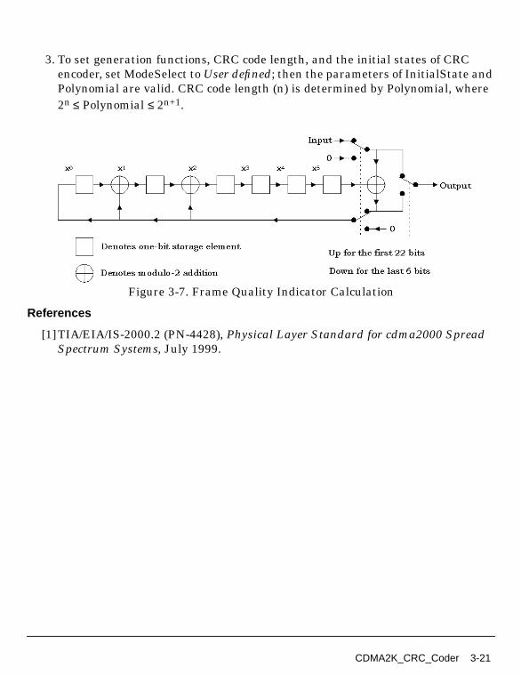
3. To set generation functions, CRC code length, and the initial states of CRCencoder, set ModeSelect to User defined; then the parameters of InitialState andPolynomial are valid. CRC code length (n) is determined by Polynomial, where2n ≤ Polynomial ≤ 2n+1.
Figure 3-7. Frame Quality Indicator Calculation
References
[1]TIA/EIA/IS-2000.2 (PN-4428), Physical Layer Standard for cdma2000 SpreadSpectrum Systems, July 1999.
CDMA2K_CRC_Coder 3-21
Channel Coding Components
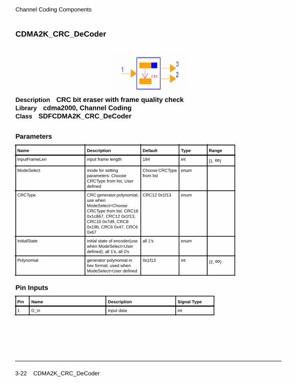
CDMA2K_CRC_DeCoder
Description CRC bit eraser with frame quality checkLibrary cdma2000, Channel CodingClass SDFCDMA2K_CRC_DeCoder
Parameters
Pin Inputs
Name Description Default Type Range
InputFrameLen input frame length 184 int [1, ∞)
ModeSelect mode for settingparameters: ChooseCRCType from list, Userdefined
Choose CRCTypefrom list
enum
CRCType CRC generator polynomial;use whenModeSelect=ChooseCRCType from list: CRC160x1c867, CRC12 0x1f13,CRC10 0x7d9, CRC80x19b, CRC6 0x47, CRC60x67
CRC12 0x1f13 enum
InitialState initial state of encoder(usewhen ModeSelect=Userdefined): all 1’s, all 0’s
all 1’s enum
Polynomial generator polynomial inhex format; used whenModeSelect=User defined
0x1f13 int (2, ∞)
Pin Name Description Signal Type
1 D_in input data int
3-22 CDMA2K_CRC_DeCoder
Pin Outputs
Notes/Equations
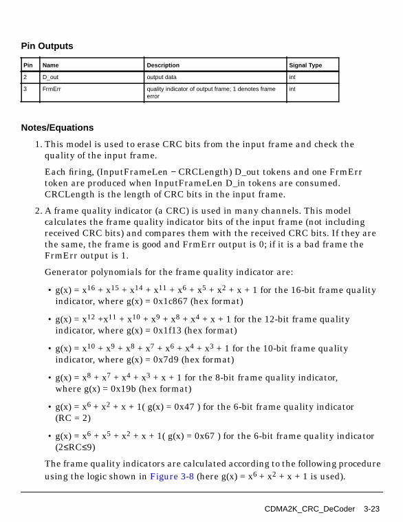
1. This model is used to erase CRC bits from the input frame and check thequality of the input frame.
Each firing, (InputFrameLen − CRCLength) D_out tokens and one FrmErrtoken are produced when InputFrameLen D_in tokens are consumed.CRCLength is the length of CRC bits in the input frame.
2. A frame quality indicator (a CRC) is used in many channels. This modelcalculates the frame quality indicator bits of the input frame (not includingreceived CRC bits) and compares them with the received CRC bits. If they arethe same, the frame is good and FrmErr output is 0; if it is a bad frame theFrmErr output is 1.
Generator polynomials for the frame quality indicator are:
• g(x) = x16 + x15 + x14 + x11 + x6 + x5 + x2 + x + 1 for the 16-bit frame qualityindicator, where g(x) = 0x1c867 (hex format)
• g(x) = x12 +x11 + x10 + x9 + x8 + x4 + x + 1 for the 12-bit frame qualityindicator, where g(x) = 0x1f13 (hex format)
• g(x) = x10 + x9 + x8 + x7 + x6 + x4 + x3 + 1 for the 10-bit frame qualityindicator, where g(x) = 0x7d9 (hex format)
• g(x) = x8 + x7 + x4 + x3 + x + 1 for the 8-bit frame quality indicator,where g(x) = 0x19b (hex format)
• g(x) = x6 + x2 + x + 1( g(x) = 0x47 ) for the 6-bit frame quality indicator(RC = 2)
• g(x) = x6 + x5 + x2 + x + 1( g(x) = 0x67 ) for the 6-bit frame quality indicator(2≤RC≤9)
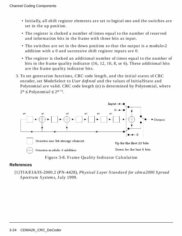
The frame quality indicators are calculated according to the following procedureusing the logic shown in Figure 3-8 (here g(x) = x6 + x2 + x + 1 is used).
Pin Name Description Signal Type
2 D_out output data int
3 FrmErr quality indicator of output frame; 1 denotes frameerror
int
CDMA2K_CRC_DeCoder 3-23
Channel Coding Components
• Initially, all shift register elements are set to logical one and the switches areset in the up position.
• The register is clocked a number of times equal to the number of reservedand information bits in the frame with those bits as input.
• The switches are set in the down position so that the output is a modulo-2addition with a 0 and successive shift register inputs are 0.
• The register is clocked an additional number of times equal to the number ofbits in the frame quality indicator (16, 12, 10, 8, or 6). These additional bitsare the frame quality indicator bits.
3. To set generation functions, CRC code length, and the initial states of CRCencoder, set ModeSelect to User defined and the values of InitialState andPolynomial are valid. CRC code length (n) is determined by Polynomial, where2n ≤ Polynomial ≤ 2n+1.
Figure 3-8. Frame Quality Indicator Calculation
References
[1]TIA/EIA/IS-2000.2 (PN-4428), Physical Layer Standard for cdma2000 SpreadSpectrum Systems, July 1999.
3-24 CDMA2K_CRC_DeCoder

CDMA2K_DCC_WithTail
Description Viterbi decoder for convolutional code with tailLibrary cdma2000, Channel CodingClass SDFCDMA2K_DCC_WithTailDerived From CDMA2K_ViterbiDecoder
Parameters
Pin Inputs
Name Description Default Type Range
ModeSelect mode for settingparameters: ChooseCCType from list, Userdefined
Choose CCTypefrom list
enum
CCType convolutional code type;used whenModeSelect=ChooseCCType from list: rate 1/2K 9 g0 0753 g1 0561, rate1/3 K 9 g0 0557 g1 0663g2 0711, rate 1/4 K 9 g00765 g1 0671 g2 0513 g30473, rate 1/6 K 9 g0 0457g1 0755 g2 0551 g3 0637g4 0625 g5_0727
rate 1/2 K 9 g00753 g1 0561
enum
ConstraintLength constraint length ofconvolutional code; usewhen ModeSelect=Userdefined
9 int
Polynomial generator polynomial 0753 0561 int array
OutputFrameLen output frame length 96 int [K, ∞)
Pin Name Description Signal Type
1 D_in input data real
CDMA2K_DCC_WithTail 3-25
Channel Coding Components
Pin Outputs
Notes/Equations
1. This model is used to decode the convolutional code frame by frame. Thedecoded frames are assumed to have K−1 tail bits.
Each firing, if ModeSelect is
• Choose CCType from list, OutputFrameLen tokens are produced whenOutputFrameLen/rate input tokens are consumed
• User defined, user input N generator functions, OutputFrameLen tokens areproduced when OutputFrameLen×N tokens are consumed.
References
[1]TIA/EIA/IS-2000.2 (PN-4428), Physical Layer Standard for cdma2000 SpreadSpectrum Systems, July 1999.
Pin Name Description Signal Type
2 D_out output decoded bits int
3-26 CDMA2K_DCC_WithTail
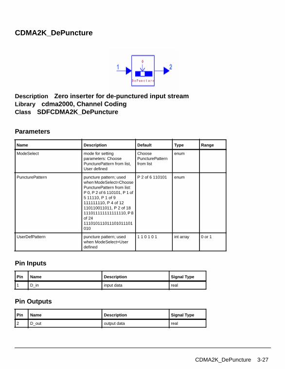
CDMA2K_DePuncture
Description Zero inserter for de-punctured input streamLibrary cdma2000, Channel CodingClass SDFCDMA2K_DePuncture
Parameters
Pin Inputs
Pin Outputs
Name Description Default Type Range
ModeSelect mode for settingparameters: ChoosePuncturePattern from list,User defined
ChoosePuncturePatternfrom list
enum
PuncturePattern puncture pattern; usedwhen ModeSelect=ChoosePuncturePattern from list:P 0, P 2 of 6 110101, P 1 of5 11110, P 1 of 9111111110, P 4 of 12110110011011, P 2 of 18111011111111111110, P 8of 24111010111011101011101010
P 2 of 6 110101 enum
UserDefPattern puncture pattern; usedwhen ModeSelect=Userdefined
1 1 0 1 0 1 int array 0 or 1
Pin Name Description Signal Type
1 D_in input data real
Pin Name Description Signal Type
2 D_out output data real
CDMA2K_DePuncture 3-27

Channel Coding Components
Notes/Equations
1. This model is used to depuncture symbols from the input frame for ratematching.
Each firing, if ModeSelect is:
• Choose PuncturePattern from list: if P n of m 11, ... , 01 is selected, m D_outtokens are produced and (m-n) D_in tokens are consumed; if P 0 is selected,puncturing will not be used, and 1 D_in token will be produced and 1 tokenwill be consumed.
• User defined, UserDefPattern is set as 11001, ... , 1, and includes m bits and n0s; then m D_out tokens are produced while (m-n) D_in tokens are consumed.
References
[1]TIA/EIA/IS-2000.2 (PN-4428), Physical Layer Standard for cdma2000 SpreadSpectrum Systems, July 1999.
3-28 CDMA2K_DePuncture

CDMA2K_FR_RateDematch
Description Flexible and variable rate de-puncture and combine repeated bitsLibrary cdma2000, Channel CodingClass SDFCDMA2K_FR_RateDematch
Parameters
Pin Inputs
Name Description Default Type Range
CodedFrmLen number of specifiedencoded symbols perframe at encoder output
768 int [1, 12288] forSR1; [1, 36864] forSR3
AssignBitNumPerFrm maximum assignednumber of channel bits perframe after coding
768 int [1, 12288] forSR1; [1, 36864] forSR3
RadioConfig radio configurations forforward and reverse linkrespectively: Forward RC3,Forward RC4, ForwardRC5, Forward RC6,Forward RC7, ForwardRC8, Forward RC9,Reverse RC3, ReverseRC4, Reverse RC5,Reverse RC6
Forward RC3 enum
ChType fundamental supplementalor dedicated controlchannel:FundamentalorSupplemental, DedicatedControl
FundamentalorSupplemental
enum
Pin Name Description Signal Type
1 D_in input data real
CDMA2K_FR_RateDematch 3-29
Channel Coding Components
Pin Outputs
Notes/Equations
1. This model is used to de-match rates for fundamental, supplemental, ordedicated control channels in flexible rate situations. It depunctures the inputsymbols then averages the symbols for different interleaver sizes and datarates.
References
[1]3GPP2 C.S0002_A_1, “Physical Layer Standard for cdma2000 Spread SpectrumSystems Release A-Addendum 1,” Oct. 27, 2000.
Pin Name Description Signal Type
2 D_out output data real
3-30 CDMA2K_FR_RateDematch

CDMA2K_FR_RateMatch
Description Flexible and variable rate repeat and punctureLibrary cdma2000, Channel CodingClass SDFCDMA2K_FR_RateMatch
Parameters
Pin Inputs
Name Description Default Type Range
CodedFrmLen number of specifiedencoded symbols perframe at encoder output
768 int [1, 12288] forSR1; [1, 36864] forSR3
AssignBitNumPerFrm maximum assignednumber of channel bits perframe after coding
768 int [1, 12288] forSR1; [1, 36864] forSR3
RadioConfig radio configurations forforward and reverse linkrespectively: Forward RC3,Forward RC4, ForwardRC5, Forward RC6,Forward RC7, ForwardRC8, Forward RC9,Reverse RC3, ReverseRC4, Reverse RC5,Reverse RC6
Forward RC3 enum
ChType fundamental supplementalor dedicated controlchannel:FundamentalorSupplemental, DedicatedControl
FundamentalorSupplemental
enum
Pin Name Description Signal Type
1 D_in input data real
CDMA2K_FR_RateMatch 3-31

Channel Coding Components
Pin Outputs
Notes/Equations
1. This model is used for flexible rate matching of fundamental, supplemental, ordedicated control channels. The input symbols are repeated and punctured fordifferent interleaver sizes.
2. If the maximum assigned data rate matches one of the corresponding radioconfiguration data rates, the interleaver size for that data rate is used.Otherwise, the interleaver size of the next higher data rate is used.
References
[1]3GPP2 C.S0002_A_1, “Physical Layer Standard for cdma2000 Spread SpectrumSystems Release A-Addendum 1,” Oct. 27, 2000.
Pin Name Description Signal Type
2 D_out output data real
3-32 CDMA2K_FR_RateMatch
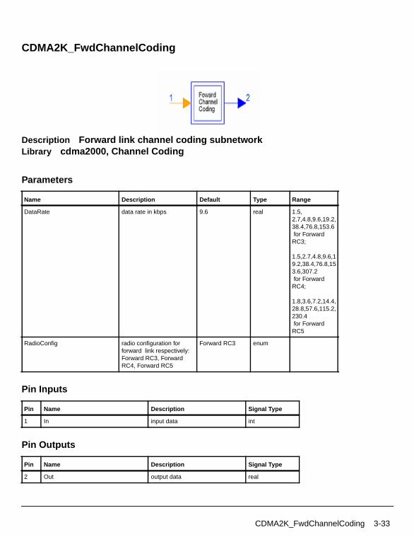
CDMA2K_FwdChannelCoding
Description Forward link channel coding subnetworkLibrary cdma2000, Channel Coding
Parameters
Pin Inputs
Pin Outputs
Name Description Default Type Range
DataRate data rate in kbps 9.6 real 1.5,2.7,4.8,9.6,19.2,38.4,76.8,153.6 for ForwardRC3;
1.5,2.7,4.8,9.6,19.2,38.4,76.8,153.6,307.2 for ForwardRC4;
1.8,3.6,7.2,14.4,28.8,57.6,115.2,230.4 for ForwardRC5
RadioConfig radio configuration forforward link respectively:Forward RC3, ForwardRC4, Forward RC5
Forward RC3 enum
Pin Name Description Signal Type
1 In input data int
Pin Name Description Signal Type
2 Out output data real
CDMA2K_FwdChannelCoding 3-33
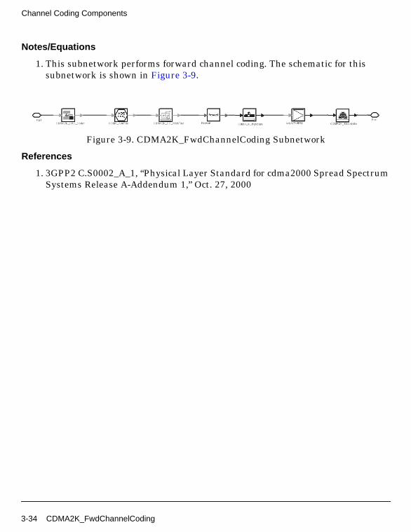
Channel Coding Components
Notes/Equations
1. This subnetwork performs forward channel coding. The schematic for thissubnetwork is shown in Figure 3-9.
Figure 3-9. CDMA2K_FwdChannelCoding Subnetwork
References
1. 3GPP2 C.S0002_A_1, “Physical Layer Standard for cdma2000 Spread SpectrumSystems Release A-Addendum 1,” Oct. 27, 2000
3-34 CDMA2K_FwdChannelCoding
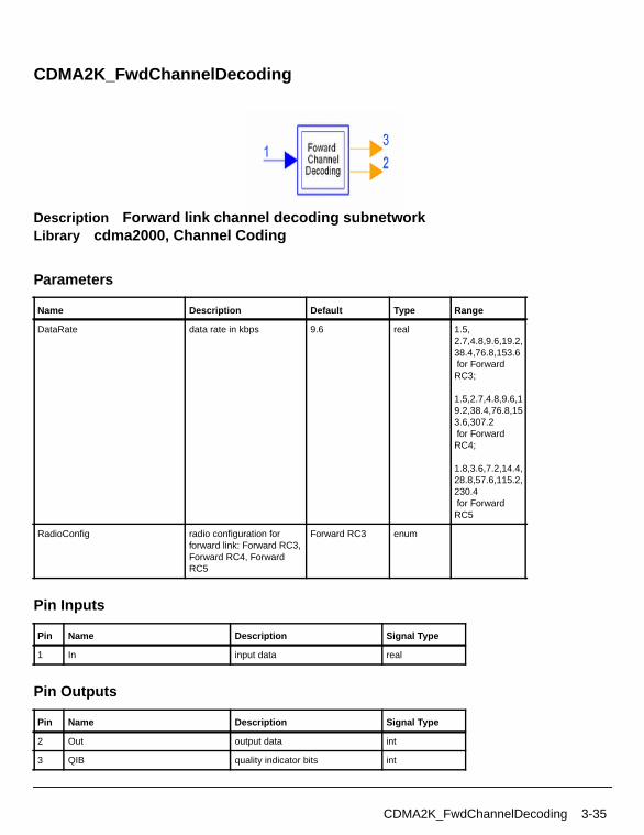
CDMA2K_FwdChannelDecoding
Description Forward link channel decoding subnetworkLibrary cdma2000, Channel Coding
Parameters
Pin Inputs
Pin Outputs
Name Description Default Type Range
DataRate data rate in kbps 9.6 real 1.5,2.7,4.8,9.6,19.2,38.4,76.8,153.6 for ForwardRC3;
1.5,2.7,4.8,9.6,19.2,38.4,76.8,153.6,307.2 for ForwardRC4;
1.8,3.6,7.2,14.4,28.8,57.6,115.2,230.4 for ForwardRC5
RadioConfig radio configuration forforward link: Forward RC3,Forward RC4, ForwardRC5
Forward RC3 enum
Pin Name Description Signal Type
1 In input data real
Pin Name Description Signal Type
2 Out output data int
3 QIB quality indicator bits int
CDMA2K_FwdChannelDecoding 3-35

Channel Coding Components
Notes/Equations
1. This subnetwork performs forward channel decoding. The schematic for thissubnetwork is shown in Figure 3-10.
Figure 3-10. CDMA2K_FwdChannelDeCoding Subnetwork
References
[1]3GPP2 C.S0002_A_1, “Physical Layer Standard for cdma2000 Spread SpectrumSystems Release A-Addendum 1,” Oct. 27, 2000
3-36 CDMA2K_FwdChannelDecoding

CDMA2K_MAPDecoder1
Description MAP decoder 1 for turbo decoderLibrary cdma2000, Channel CodingClass SDFCDMA2K_MAPDecoder1
Parameters
Pin Inputs
Pin Outputs
Notes/Equations
1. This model is used to decode turbo code with MAP algorithm (maximum aposterior). It is a modified BAHL et al. algorithm for RSC code. Two parallelconcatenated MAP decoders are used. If the Polynomial has M components,then the turbo code rate will be 1/M.
Name Description Default Sym Type Range
BlockSize number of particles in ablock
378 L int (0, 65536]
ConstraintLength constraint length of RSCencoder in turbo encoder
4 K int [3, 9]
Polynomial generator polynomial 015 013 017 int array
Pin Name Description Signal Type
1 D_in input data real
2 InPri input priori probability real
Pin Name Description Signal Type
3 Post output a posteriori probability real
CDMA2K_MAPDecoder1 3-37

Channel Coding Components
Each firing, L Post tokens are produced when L×M D_in tokens and M InPritokens are consumed.
References
[1]L. R. Bahl, J. Cocke, F. Jeinek and J. Raviv. “Optimal decoding of linear codesfor minimizing symbol error rate,” IEEE Trans. Inform. Theory, vol. IT-20.March 1974, pp. 248-287.
[2] C. Berrou, A. Glavieux, and P. Thitiumjshima, “Near Shannon limit errorcorrecting coding: Turbo codes,” IEEE International Conference onCommunications, May 1993, pp. 1064-1070.
3-38 CDMA2K_MAPDecoder1
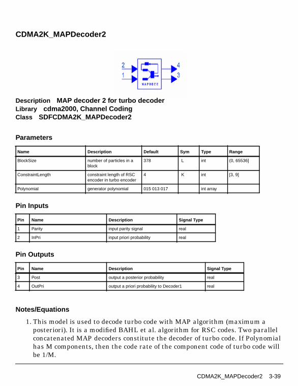
CDMA2K_MAPDecoder2
Description MAP decoder 2 for turbo decoderLibrary cdma2000, Channel CodingClass SDFCDMA2K_MAPDecoder2
Parameters
Pin Inputs
Pin Outputs
Notes/Equations
1. This model is used to decode turbo code with MAP algorithm (maximum aposteriori). It is a modified BAHL et al. algorithm for RSC codes. Two parallelconcatenated MAP decoders constitute the decoder of turbo code. If Polynomialhas M components, then the code rate of the component code of turbo code willbe 1/M.
Name Description Default Sym Type Range
BlockSize number of particles in ablock
378 L int (0, 65536]
ConstraintLength constraint length of RSCencoder in turbo encoder
4 K int [3, 9]
Polynomial generator polynomial 015 013 017 int array
Pin Name Description Signal Type
1 Parity input parity signal real
2 InPri input priori probability real
Pin Name Description Signal Type
3 Post output a posterior probability real
4 OutPri output a priori probability to Decoder1 real
CDMA2K_MAPDecoder2 3-39
Channel Coding Components
Each firing, L Post tokens and L OutPri tokens are produced when L×(M-1)Parity tokens and L InPri tokens are consumed.
References
[1]L. R. Bahl, J. Cocke, F. Jeinek and J. Raviv. “Optimal decoding of linear codesfor minimizing symbol error rate,” IEEE Trans. Inform. Theory, vol. IT-20.March 1974, pp. 248-287.
[2] C. Berrou, A. Glavieux, and P. Thitiumjshima, “Near Shannon limit errorcorrecting coding: Turbo codes,” IEEE International Conference onCommunications, May 1993, pp. 1064-1070.
3-40 CDMA2K_MAPDecoder2
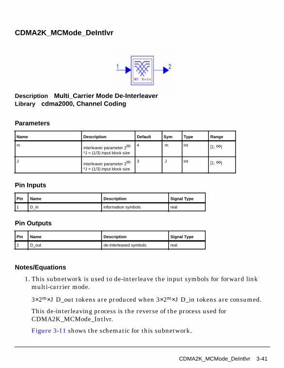
CDMA2K_MCMode_DeIntlvr
Description Multi_Carrier Mode De-InterleaverLibrary cdma2000, Channel Coding
Parameters
Pin Inputs
Pin Outputs
Notes/Equations
1. This subnetwork is used to de-interleave the input symbols for forward linkmulti-carrier mode.
3×2m×J D_out tokens are produced when 3×2m×J D_in tokens are consumed.
This de-interleaving process is the reverse of the process used forCDMA2K_MCMode_Intlvr.
Figure 3-11 shows the schematic for this subnetwork.
Name Description Default Sym Type Range
minterleaver parameter 2m*J = (1/3) input block size
4 m int [1, ∞)
Jinterleaver parameter 2m*J = (1/3) input block size
3 J int [1, ∞)
Pin Name Description Signal Type
1 D_in information symbols real
Pin Name Description Signal Type
2 D_out de-interleaved symbols real
CDMA2K_MCMode_DeIntlvr 3-41
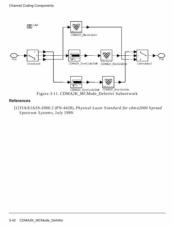
Channel Coding Components
Figure 3-11. CDMA2K_MCMode_DeIntlvr Subnetwork
References
[1]TIA/EIA/IS-2000.2 (PN-4428), Physical Layer Standard for cdma2000 SpreadSpectrum Systems, July 1999.
3-42 CDMA2K_MCMode_DeIntlvr
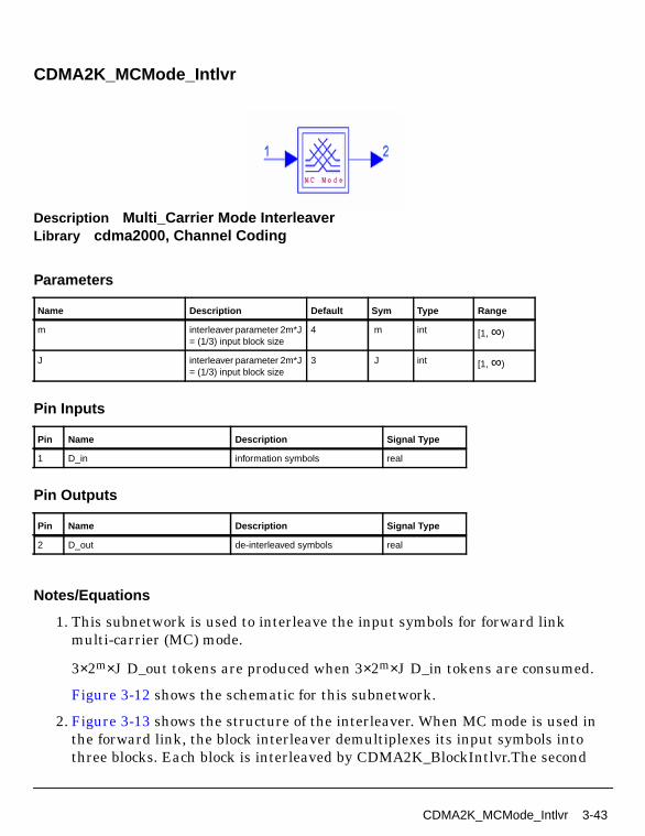
CDMA2K_MCMode_Intlvr
Description Multi_Carrier Mode InterleaverLibrary cdma2000, Channel Coding
Parameters
Pin Inputs
Pin Outputs
Notes/Equations
1. This subnetwork is used to interleave the input symbols for forward linkmulti-carrier (MC) mode.
3×2m×J D_out tokens are produced when 3×2m×J D_in tokens are consumed.
Figure 3-12 shows the schematic for this subnetwork.
2. Figure 3-13 shows the structure of the interleaver. When MC mode is used inthe forward link, the block interleaver demultiplexes its input symbols intothree blocks. Each block is interleaved by CDMA2K_BlockIntlvr.The second
Name Description Default Sym Type Range
m interleaver parameter 2m*J= (1/3) input block size
4 m int [1, ∞)
J interleaver parameter 2m*J= (1/3) input block size
3 J int [1, ∞)
Pin Name Description Signal Type
1 D_in information symbols real
Pin Name Description Signal Type
2 D_out de-interleaved symbols real
CDMA2K_MCMode_Intlvr 3-43
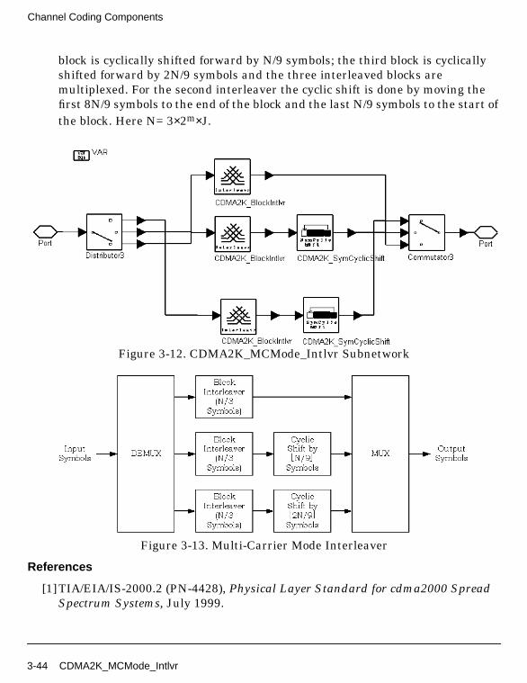
Channel Coding Components
block is cyclically shifted forward by N/9 symbols; the third block is cyclicallyshifted forward by 2N/9 symbols and the three interleaved blocks aremultiplexed. For the second interleaver the cyclic shift is done by moving thefirst 8N/9 symbols to the end of the block and the last N/9 symbols to the start ofthe block. Here N= 3×2m×J.
Figure 3-12. CDMA2K_MCMode_Intlvr Subnetwork
Figure 3-13. Multi-Carrier Mode Interleaver
References
[1]TIA/EIA/IS-2000.2 (PN-4428), Physical Layer Standard for cdma2000 SpreadSpectrum Systems, July 1999.
3-44 CDMA2K_MCMode_Intlvr

CDMA2K_OneWay
Description One Way Decoder with Constant Rate for Blind DetectionLibrary cdma2000, Channel Coding
Parameters
Pin Inputs
Pin Outputs
Notes/Equations
1. This subnetwork is used to implement channel decoding according to the datarate and radio configuration specified. It includes averaging, depuncturing,Viterbi decoding, convolutional encoding, and BER measurement. Figure 3-14shows the schematic for this subnetwork.
Name Description Default Type
RadioConfig radio configuration: FwdRC1, Fwd RC2, Fwd RC3,Fwd RC4, Fwd RC5, FwdRC6, Fwd RC7, Fwd RC8,Fwd RC9, Rev RC3, RevRC4, Rev RC5, Rev RC6
Fwd RC1 enum
DataRate data rate: Full Rate, HalfRate, Rate1-4, Rate1-8
Full Rate enum
Pin Name Description Signal Type
1 D_in input data real
Pin Name Description Signal Type
2 BER error rate of this output frame real
3 BitOut decoded bits int
CDMA2K_OneWay 3-45
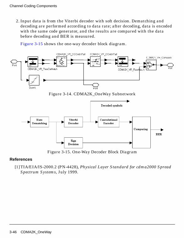
Channel Coding Components
2. Input data is from the Viterbi decoder with soft decision. Dematching anddecoding are performed according to data rate; after decoding, data is encodedwith the same code generator, and the results are compared with the databefore decoding and BER is measured.
Figure 3-15 shows the one-way decoder block diagram.
Figure 3-14. CDMA2K_OneWay Subnetwork
Figure 3-15. One-Way Decoder Block Diagram
References
[1]TIA/EIA/IS-2000.2 (PN-4428), Physical Layer Standard for cdma2000 SpreadSpectrum Systems, July 1999.
3-46 CDMA2K_OneWay

CDMA2K_OnewayRevRC1_2
Description One Way Decoder for Blind Decoder in Reverse Link RC1, RC2Library cdma2000, Channel Coding
Parameters
Pin Inputs
Pin Outputs
Notes/Equations
1. This subnetwork is used to implement channel decoding for reverse RC1 orRC2. It includes Viterbi decoding, convolutional encoding, and BERmeasurement.
Figure 3-16 shows the schematic for this subnetwork.
2. Input data is from the Viterbi decoder with soft decision. Rate dematching anddecoding are performed according to data rate; after decoding data is encoded
Name Description Default Type
RadioConfig radio configuration: RevRC1, Rev RC2
Rev RC1 enum
DataRate data rate: Full Rate, HalfRate, Rate1_4, Rate1_8
Full Rate enum
Pin Name Description Signal Type
1 D_in input data real
Pin Name Description Signal Type
2 BER error rate of this output frame real
3 BitOut decoded bits int
CDMA2K_OnewayRevRC1_2 3-47
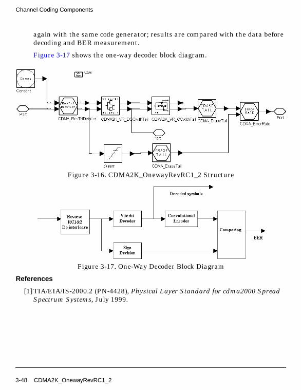
Channel Coding Components
again with the same code generator; results are compared with the data beforedecoding and BER measurement.
Figure 3-17 shows the one-way decoder block diagram.
Figure 3-16. CDMA2K_OnewayRevRC1_2 Structure
Figure 3-17. One-Way Decoder Block Diagram
References
[1]TIA/EIA/IS-2000.2 (PN-4428), Physical Layer Standard for cdma2000 SpreadSpectrum Systems, July 1999.
3-48 CDMA2K_OnewayRevRC1_2
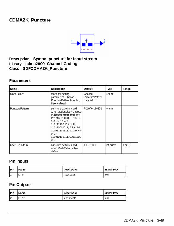
CDMA2K_Puncture
Description Symbol puncture for input streamLibrary cdma2000, Channel CodingClass SDFCDMA2K_Puncture
Parameters
Pin Inputs
Pin Outputs
Name Description Default Type Range
ModeSelect mode for settingparameters: ChoosePuncturePattern from list,User defined
ChoosePuncturePatternfrom list
enum
PuncturePattern puncture pattern; usedwhen ModeSelect=ChoosePuncturePattern from list:P 2 of 6 110101, P 1 of 511110, P 1 of 9111111110, P 4 of 12110110011011, P 2 of 18111011111111111110, P 8of 24111010111011101011101010
P 2 of 6 110101 enum
UserDefPattern puncture pattern; usedwhen ModeSelect=Userdefined
1 1 0 1 0 1 int array 1 or 0
Pin Name Description Signal Type
1 D_in input data real
Pin Name Description Signal Type
2 D_out output data real
CDMA2K_Puncture 3-49
Channel Coding Components
Notes/Equations
1. This model is used to puncture symbols from input frame for rate matching.
Each firing, if ModeSelect is
• Choose PuncturePattern from list (P n of m 11, ... , 01 is selected) (m-n) D_outtokens are produced for m D_in tokens consumed.
• User defined, UserDefPattern is set as 11001, ... , 1, and includes m bits and n0s. (m - n) D_out tokens are produced for m D_in tokens consumed.
References
[1]TIA/EIA/IS-2000.2 (PN-4428), Physical Layer Standard for cdma2000 SpreadSpectrum Systems, July 1999.
3-50 CDMA2K_Puncture

CDMA2K_RevChannelCoding
Description reverse link channel coding subnetworkLibrary cdma2000, Channel Coding
Parameters
Pin Inputs
Name Description Default Type Range
DataRate data rate in kbps 9.6 real 1.5,2.7,4.8,9.6,19.2,38.4,76.8,153.6,307.2 for ReverseRC3;
1.8,3.6,7.2,14.4,28.8,57.6,115.2,230.4 for ReverseRC4
1.5,2.7,4.8,9.6,19.2,38.4,76.8,153.6,307.2,614.4 for ReverseRC5;
1.8,3.6,7.2,14.4,28.8,57.6,115.2,230.4,460.8,1036.8 for ReverseRC6
RadioConfig radio configuration forreverse link respectively:Reverse RC3, ReverseRC4, Reverse RC5,Reverse RC6
Reverse RC3 enum
Pin Name Description Signal Type
1 In input data int
CDMA2K_RevChannelCoding 3-51
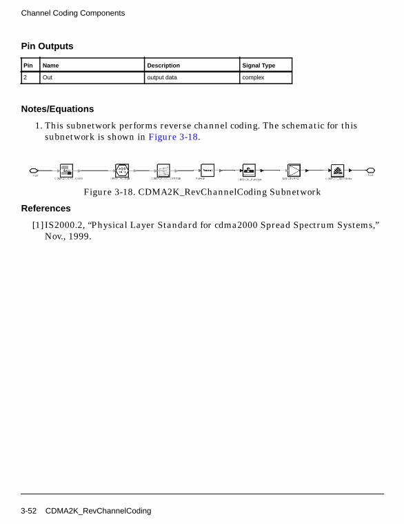
Channel Coding Components
Pin Outputs
Notes/Equations
1. This subnetwork performs reverse channel coding. The schematic for thissubnetwork is shown in Figure 3-18.
Figure 3-18. CDMA2K_RevChannelCoding Subnetwork
References
[1] IS2000.2, “Physical Layer Standard for cdma2000 Spread Spectrum Systems,”Nov., 1999.
Pin Name Description Signal Type
2 Out output data complex
3-52 CDMA2K_RevChannelCoding

CDMA2K_RevChannelDecoding
Description reverse link channel decoding subnetworkLibrary cdma2000, Channel Coding
Parameters
Pin Inputs
Name Description Default Type Range
DataRate data rate in kbps 9.6 real 1.5,2.7,4.8,9.6,19.2,38.4,76.8,153.6,307.2 for ReverseRC3;
1.8,3.6,7.2,14.4,28.8,57.6,115.2,230.4 for ReverseRC4
1.5,2.7,4.8,9.6,19.2,38.4,76.8,153.6,307.2,614.4 for ReverseRC5;
1.8,3.6,7.2,14.4,28.8,57.6,115.2,230.4,460.8,1036.8 for ReverseRC6
RadioConfig radio configuration forreverse link respectively:Reverse RC3, ReverseRC4, Reverse RC5,Reverse RC6
Reverse RC3 enum
Pin Name Description Signal Type
1 In input data real
CDMA2K_RevChannelDecoding 3-53
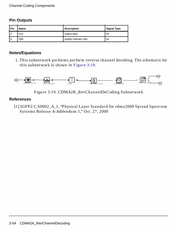
Channel Coding Components
Pin Outputs
Notes/Equations
1. This subnetwork performs perform reverse channel decoding. The schematic forthis subnetwork is shown in Figure 3-19.
Figure 3-19. CDMA2K_RevChannelDeCoding Subnetwork
References
[1]3GPP2 C.S0002_A_1, “Physical Layer Standard for cdma2000 Spread SpectrumSystems Release A-Addendum 1,” Oct. 27, 2000
Pin Name Description Signal Type
2 Out output data int
3 QIB quality indicator bits int
3-54 CDMA2K_RevChannelDecoding
CDMA2K_SymCyclicShift
Description Cyclic shifter for MC Mode interleaverLibrary cdma2000, Channel CodingClass SDFCDMA2K_SymCyclicShift
Parameters
Pin Inputs
Pin Outputs
Notes/Equations
1. This model is used to cyclic shift symbols before interleaving by themulti-carrier mode interleaver.
Each firing, BlockSize D_out tokens are produced when BlockSize D_in tokensare consumed.
2. If CyclicFormat is set as n m, the first (1- n/m)×BlockSize symbols are moved tothe end of the block and the last n/m symbols are moved to the start of theblock.
Name Description Default Type
BlockSize number of particles in ablock
576 int
CyclicFormat cyclic shifter format 2 9 int array
Pin Name Description Signal Type
1 D_in input data real
Pin Name Description Signal Type
2 D_out output data real
CDMA2K_SymCyclicShift 3-55
Channel Coding Components
References
[1]TIA/EIA/IS-2000.2 (PN-4428), Physical Layer Standard for cdma2000 SpreadSpectrum Systems, July 1999.
3-56 CDMA2K_SymCyclicShift

CDMA2K_TurboDecoder
Description 4-Level Turbo DecoderLibrary cdma2000, Channel Coding
Parameters
Pin Inputs
Pin Outputs
Notes/Equations
1. This subnetwork is used to implement 4-level iterative MAP decodingalgorithm for turbo code.
N PriOut and N BitOut tokens are produced when ((N+6)/CodeRate) D_intokens are consumed.
Figure 3-20 shows the schematic for this subnetwork.
Name Description Default Sym Type Range
OutputFrameLen output frame length (notincluding 6 tail bits)
378 N int [256, ∞)
CodeRate code rate of turbo encoder:rate 1/2, rate 1/3, rate 1/4
rate 1/2 enum
Pin Name Description Signal Type
1 D_in input data real
Pin Name Description Signal Type
2 PriOut priori value for next decoder real
3 BitOut decoded bits int
CDMA2K_TurboDecoder 3-57

Channel Coding Components
Figure 3-20. CDMA2K_TurboDecoder Subnetwork
References
[1]L. R. Bahl, J. Cocke, F. Jeinek and J. Raviv. “Optimal decoding of linear codesfor minimizing symbol error rate,” IEEE Trans. Inform. Theory, vol. IT-20.March 1974, pp. 248-287.
[2] C. Berrou, A. Glavieux, and P. Thitiumjshima, “Near Shannon limit errorcorrecting coding: Turbo codes,” IEEE International Conference onCommunications, May 1993, pp. 1064-1070.
[3] TIA/EIA/IS-2000.2 (PN-4428), Physical Layer Standard for cdma2000 SpreadSpectrum Systems, July 1999.
3-58 CDMA2K_TurboDecoder
CDMA2K_TurboDeIntlvr
Description De-interleaver for turbo codeLibrary cdma2000, Channel CodingClass SDFCDMA2K_TurboDeIntlvr
Parameters
Pin Inputs
Pin Outputs
Notes/Equations
1. This model is used to de-interleave the input symbols for turbo code.
Each firing, Nturbo output tokens are produced when Nturbo input tokens areconsumed.
2. The turbo de-interleaver process is the reverse of that used in theCDMA2K_TurboIntlvr. Functionally, it is the same; the entire sequence of turbointerleaver input bits are written sequentially into an array at a sequence ofaddresses, and the entire sequence is read out from a sequence of addresses.
References
Name Description Default Sym Type Range
BlockSize number of particles in ablock
378 Nturbo int [256, ∞)
Pin Name Description Signal Type
1 D_in input data real
Pin Name Description Signal Type
2 D_out output data real
CDMA2K_TurboDeIntlvr 3-59

Channel Coding Components
[1]TIA/EIA/IS-2000.2 (PN-4428), Physical Layer Standard for cdma2000 SpreadSpectrum Systems, July 1999.
3-60 CDMA2K_TurboDeIntlvr
CDMA2K_TurboDeMux
Description De-puncture and de-mux for turbo decoderLibrary cdma2000, Channel CodingClass SDFCDMA2K_TurboDeMux
Parameters
Pin Inputs
Pin Outputs
Notes/Equations
1. This model is used to demultiplex, depuncture or delete tail symbols for theturbo decoder.
Name Description Default Sym Type Range
BlockSize number of particles in ablock
768 N int [6/R, ∞)
CodeRate code rate of turbo encoder:CodeRate1/2,CodeRate1/3,CodeRate1/4
CodeRate1/2 R enum
Pin Name Description Signal Type
1 D_in input data real
Pin Name Description Signal Type
2 C1_X X output of decoder#1 real
3 C1_Y0 Y0 output of decoder#1 real
4 C1_Y1 Y1 output of decoder#1 real
5 C2_Y0 Y0 output of decoder#2 real
6 C2_Y1 Y1 output of decoder#2 real
CDMA2K_TurboDeMux 3-61
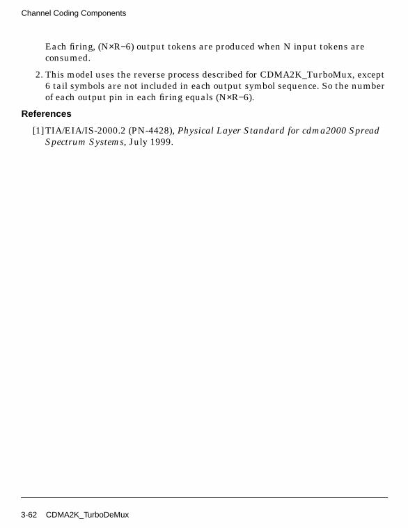
Channel Coding Components
Each firing, (N×R−6) output tokens are produced when N input tokens areconsumed.
2. This model uses the reverse process described for CDMA2K_TurboMux, except6 tail symbols are not included in each output symbol sequence. So the numberof each output pin in each firing equals (N×R−6).
References
[1]TIA/EIA/IS-2000.2 (PN-4428), Physical Layer Standard for cdma2000 SpreadSpectrum Systems, July 1999.
3-62 CDMA2K_TurboDeMux

CDMA2K_TurboEncoder
Description Turbo EncoderLibrary cdma2000, Channel Coding
Parameters
Pin Inputs
Pin Outputs
Notes/Equations
1. This subnetwork is a turbo encoder.
(N/CodeRate) output tokens are produced when N input tokens are consumed.
Figure 3-21 shows the schematic for this subnetwork.
Name Description Default Sym Type Range
InputFrameLen input frame lengthincluding 6 tail bits
384 N int [262, ∞)
CodeRate code rate of Turboencoder: rate 1/2, rate 1/3,rate 1/4
rate 1/2 enum
Pin Name Description Signal Type
1 D_in input data int
Pin Name Description Signal Type
2 D_Out output data int
CDMA2K_TurboEncoder 3-63

Channel Coding Components
Figure 3-21. CDMA2K_TurboEncoder Subnetwork
2. The turbo encoder uses two parallel concatenated RSC (recursive systematicconvolutional) encoders with an interleaver before the second RSC encoder. Thetwo recursive convolutional codes are named the constituent codes of the turbocode. The outputs of the constituent encoders are punctured and repeated toachieve the (Nturbo + 6)/R output symbols.
A common constituent code (RSC code) is used for turbo codes of rate 1/2, 1/3,and 1/4. The transfer function for the constituent code is
where d(D) = 1 + D2 + D3, n0(D) = 1 + D + D3, and n1(D) = 1 + D + D2 + D3.
The turbo encoder generates an output symbol sequence that is shown inFigure 3-22. Initially, the states of the constituent encoder registers are set to 0.
G D( ) 1n0 D( )d D( )----------------
n1 D( )d D( )----------------
n2 D( )d D( )----------------, ,[ , ]=
3-64 CDMA2K_TurboEncoder
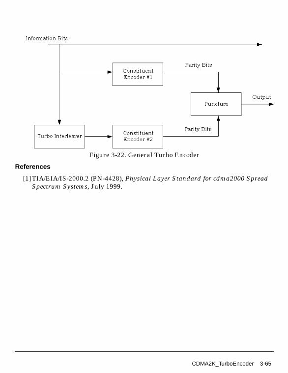
Figure 3-22. General Turbo Encoder
References
[1]TIA/EIA/IS-2000.2 (PN-4428), Physical Layer Standard for cdma2000 SpreadSpectrum Systems, July 1999.
CDMA2K_TurboEncoder 3-65
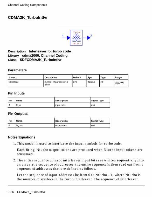
Channel Coding Components
CDMA2K_TurboIntlvr
Description Interleaver for turbo codeLibrary cdma2000, Channel CodingClass SDFCDMA2K_TurboIntlvr
Parameters
Pin Inputs
Pin Outputs
Notes/Equations
1. This model is used to interleave the input symbols for turbo code.
Each firing, Nturbo output tokens are produced when Nturbo input tokens areconsumed.
2. The entire sequence of turbo interleaver input bits are written sequentially intoan array at a sequence of addresses; the entire sequence is then read out from asequence of addresses that are defined as follows.
Let the sequence of input addresses be from 0 to Nturbo – 1, where Nturbo isthe number of symbols in the turbo interleaver. The sequence of interleaver
Name Description Default Sym Type Range
BlockSize number of particles in ablock
378 Nturbo int [256, ∞)
Pin Name Description Signal Type
1 D_in input data real
Pin Name Description Signal Type
2 D_out output data real
3-66 CDMA2K_TurboIntlvr
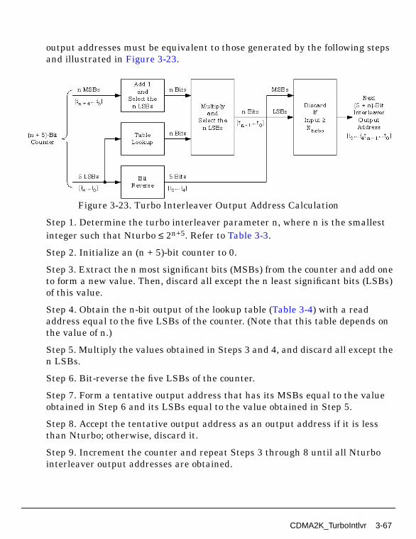
output addresses must be equivalent to those generated by the following stepsand illustrated in Figure 3-23.
Figure 3-23. Turbo Interleaver Output Address Calculation
Step 1. Determine the turbo interleaver parameter n, where n is the smallestinteger such that Nturbo ≤ 2n+5. Refer to Table 3-3.
Step 2. Initialize an (n + 5)-bit counter to 0.
Step 3. Extract the n most significant bits (MSBs) from the counter and add oneto form a new value. Then, discard all except the n least significant bits (LSBs)of this value.
Step 4. Obtain the n-bit output of the lookup table (Table 3-4) with a readaddress equal to the five LSBs of the counter. (Note that this table depends onthe value of n.)
Step 5. Multiply the values obtained in Steps 3 and 4, and discard all except then LSBs.
Step 6. Bit-reverse the five LSBs of the counter.
Step 7. Form a tentative output address that has its MSBs equal to the valueobtained in Step 6 and its LSBs equal to the value obtained in Step 5.
Step 8. Accept the tentative output address as an output address if it is lessthan Nturbo; otherwise, discard it.
Step 9. Increment the counter and repeat Steps 3 through 8 until all Nturbointerleaver output addresses are obtained.
CDMA2K_TurboIntlvr 3-67

Channel Coding Components
Table 3-3. Turbo Interleaver Parameters
Turbo Interleaver BlockSize Nturbo Turbo Interleaver Parameter n
378 4
570 5
762 5
1,146 6
1,530 6
2,298 7
3,066 7
4,602 8
6,138 8
9,210 9
12,282 9
20,730 10
Table 3-4. Turbo Interleaver Lookup Table Definition
TableIndex n = 4 n = 5 n = 6 n = 7 n = 8 n = 9 n = 10
0 5 27 3 15 3 13 1
1 15 3 27 127 1 335 349
2 5 1 15 89 5 87 303
3 15 15 13 1 83 15 721
4 1 13 29 31 19 15 973
5 9 17 5 15 179 1 703
6 9 23 1 61 19 333 761
7 15 13 31 47 99 11 327
8 13 9 3 127 23 13 453
9 15 3 9 17 1 1 95
10 7 15 15 119 3 121 241
11 11 3 31 15 13 155 187
12 15 13 17 57 13 1 497
13 3 1 5 123 3 175 909
14 15 13 39 95 17 421 769
15 5 29 1 5 1 5 349
16 13 21 19 85 63 509 71
17 15 19 27 17 131 215 557
3-68 CDMA2K_TurboIntlvr
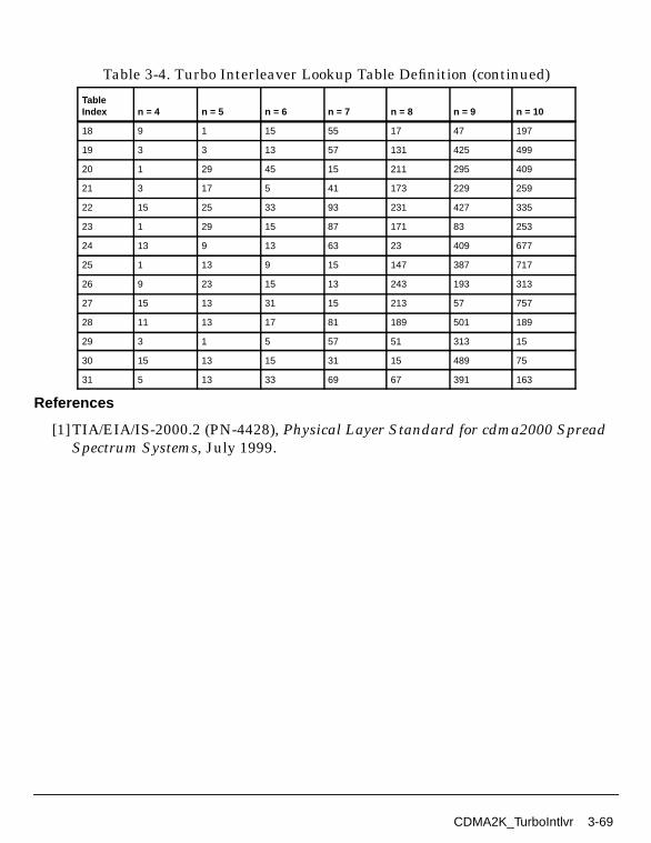
References
[1]TIA/EIA/IS-2000.2 (PN-4428), Physical Layer Standard for cdma2000 SpreadSpectrum Systems, July 1999.
18 9 1 15 55 17 47 197
19 3 3 13 57 131 425 499
20 1 29 45 15 211 295 409
21 3 17 5 41 173 229 259
22 15 25 33 93 231 427 335
23 1 29 15 87 171 83 253
24 13 9 13 63 23 409 677
25 1 13 9 15 147 387 717
26 9 23 15 13 243 193 313
27 15 13 31 15 213 57 757
28 11 13 17 81 189 501 189
29 3 1 5 57 51 313 15
30 15 13 15 31 15 489 75
31 5 13 33 69 67 391 163
Table 3-4. Turbo Interleaver Lookup Table Definition (continued)
TableIndex n = 4 n = 5 n = 6 n = 7 n = 8 n = 9 n = 10
CDMA2K_TurboIntlvr 3-69
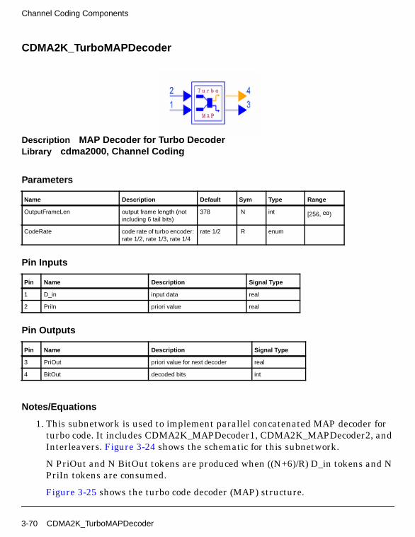
Channel Coding Components
CDMA2K_TurboMAPDecoder
Description MAP Decoder for Turbo DecoderLibrary cdma2000, Channel Coding
Parameters
Pin Inputs
Pin Outputs
Notes/Equations
1. This subnetwork is used to implement parallel concatenated MAP decoder forturbo code. It includes CDMA2K_MAPDecoder1, CDMA2K_MAPDecoder2, andInterleavers. Figure 3-24 shows the schematic for this subnetwork.
N PriOut and N BitOut tokens are produced when ((N+6)/R) D_in tokens and NPriIn tokens are consumed.
Figure 3-25 shows the turbo code decoder (MAP) structure.
Name Description Default Sym Type Range
OutputFrameLen output frame length (notincluding 6 tail bits)
378 N int [256, ∞)
CodeRate code rate of turbo encoder:rate 1/2, rate 1/3, rate 1/4
rate 1/2 R enum
Pin Name Description Signal Type
1 D_in input data real
2 Priln priori value real
Pin Name Description Signal Type
3 PriOut priori value for next decoder real
4 BitOut decoded bits int
3-70 CDMA2K_TurboMAPDecoder
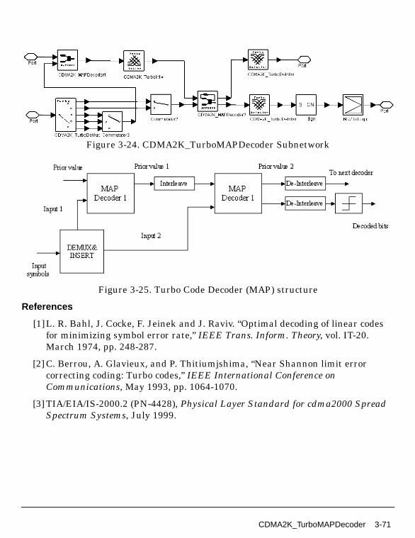
Figure 3-24. CDMA2K_TurboMAPDecoder Subnetwork
Figure 3-25. Turbo Code Decoder (MAP) structure
References
[1]L. R. Bahl, J. Cocke, F. Jeinek and J. Raviv. “Optimal decoding of linear codesfor minimizing symbol error rate,” IEEE Trans. Inform. Theory, vol. IT-20.March 1974, pp. 248-287.
[2] C. Berrou, A. Glavieux, and P. Thitiumjshima, “Near Shannon limit errorcorrecting coding: Turbo codes,” IEEE International Conference onCommunications, May 1993, pp. 1064-1070.
[3] TIA/EIA/IS-2000.2 (PN-4428), Physical Layer Standard for cdma2000 SpreadSpectrum Systems, July 1999.
CDMA2K_TurboMAPDecoder 3-71

Channel Coding Components
CDMA2K_TurboMux
Description Multiplexer for turbo codeLibrary cdma2000, Channel CodingClass SDFCDMA2K_TurboMux
Parameters
Pin Inputs
Pin Outputs
Notes/Equations
1. This model is used to repeat, puncture, and multiplex the input symbols forturbo encoder.
Name Description Default Sym Type Range
InputFrameLen input frame length 384 N int [6/R, ∞)
CodeRate code rate of turbo code:CodeRate1/2,CodeRate1/3,CodeRate1/4
CodeRate1/2 R enum
Pin Name Description Signal Type
1 C1_X X output of Encoder#1 int
2 C1_Y0 Y0 output of Encoder#1 int
3 C1_Y1 Y1 output of Encoder#1 int
4 C2_X X output of Encoder#2 int
5 C2_Y0 Y0 output of Encoder#2 int
6 C2_Y1 Y1 output of Encoder#2 int
Pin Name Description Signal Type
7 D_out output data int
3-72 CDMA2K_TurboMux

Each firing, N/R output tokens are produced when N of each input tokens areconsumed.
2. The RSC encoder output symbol puncturing and repetition are specified inTable 3-5 and Table 3-6. Within a puncturing pattern, 0 means the symbol willbe deleted and 1 means the symbol will be passed.
For rate 1/2 turbo codes, the tail output symbols for each of the first three tailbit periods will be XY0, and the tail output symbols for each of the last three tailbit periods shall be X′Y′0.
For rate 1/3 turbo codes, the tail output symbols for each of the first three tailbit periods will be XXY0, and the tail output symbols for each of the last threetail bit periods shall be X′X′Y′0.
For rate 1/4 turbo codes, the tail output symbols for each of the first three tailbit periods will be XXY0Y1, and the tail output symbols for each of the last threetail bit periods will be X′X′Y′0Y′.
Table 3-5. Puncturing Patterns for Data Bit Periods
Output
Code Rate
1/2 1/3 1/4
X 11 11 11
Y0 10 11 11
Y1 00 00 10
X′ 00 00 00
Y′001 11 01
Y′100 00 11
Note: For each rate, the puncturing table is read top to bottom, then left to right.
Table 3-6. Puncturing Patterns for Tail Bit Periods
Output
Code Rate
1/2 1/3 1/4
X 111 000 111 000 111 000
Y0 111 000 111 000 111 000
Y1 000 000 000 000 111 000
X′ 000 111 000 111 000 111
CDMA2K_TurboMux 3-73
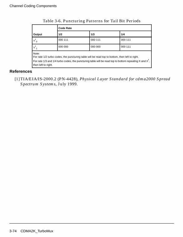
Channel Coding Components
References
[1]TIA/EIA/IS-2000.2 (PN-4428), Physical Layer Standard for cdma2000 SpreadSpectrum Systems, July 1999.
Y′0000 111 000 111 000 111
Y′1000 000 000 000 000 111
Note:For rate 1/2 turbo codes, the puncturing table will be read top to bottom, then left to right.
For rate 1/3 and 1/4 turbo codes, the puncturing table will be read top to bottom repeating X and X′,then left to right.
Table 3-6. Puncturing Patterns for Tail Bit Periods
Output
Code Rate
1/2 1/3 1/4
3-74 CDMA2K_TurboMux
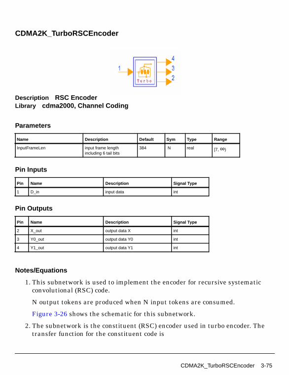
CDMA2K_TurboRSCEncoder
Description RSC EncoderLibrary cdma2000, Channel Coding
Parameters
Pin Inputs
Pin Outputs
Notes/Equations
1. This subnetwork is used to implement the encoder for recursive systematicconvolutional (RSC) code.
N output tokens are produced when N input tokens are consumed.
Figure 3-26 shows the schematic for this subnetwork.
2. The subnetwork is the constituent (RSC) encoder used in turbo encoder. Thetransfer function for the constituent code is
Name Description Default Sym Type Range
InputFrameLen input frame lengthincluding 6 tail bits
384 N real [7, ∞)
Pin Name Description Signal Type
1 D_in input data int
Pin Name Description Signal Type
2 X_out output data X int
3 Y0_out output data Y0 int
4 Y1_out output data Y1 int
CDMA2K_TurboRSCEncoder 3-75
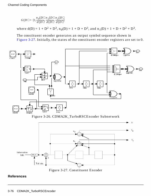
Channel Coding Components
where d(D) = 1 + D2 + D3, n0(D) = 1 + D + D3, and n1(D) = 1 + D + D2 + D3.
The constituent encoder generates an output symbol sequence shown inFigure 3-27. Initially, the states of the constituent encoder registers are set to 0.
Figure 3-26. CDMA2K_TurboRSCEncoder Subnetwork
Figure 3-27. Constituent Encoder
References
G D( ) 1n0 D( )d D( )----------------
n1 D( )d D( )----------------
n2 D( )d D( )----------------, ,[ , ]=
3-76 CDMA2K_TurboRSCEncoder
[1]TIA/EIA/IS-2000.2 (PN-4428), Physical Layer Standard for cdma2000 SpreadSpectrum Systems, July 1999.
CDMA2K_TurboRSCEncoder 3-77
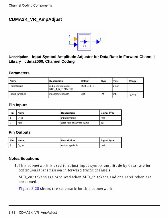
Channel Coding Components
CDMA2K_VR_AmpAdjust
Description Input Symbol Amplitude Adjuster for Data Rate in Forward ChannelLibrary cdma2000, Channel Coding
Parameters
Pin Inputs
Pin Outputs
Notes/Equations
1. This subnetwork is used to adjust input symbol amplitude by data rate forcontinuous transmission in forward traffic channels.
M D_out tokens are produced when M D_in tokens and one rateI token areconsumed.
Figure 3-28 shows the schematic for this subnetwork.
Name Description Default Sym Type Range
RadioConfig radio configuration:RC3_4_6_7, otherRC
RC3_4_6_7 enum
InputFrameLen input frame length 384 M int [1, ∞)
Pin Name Description Signal Type
1 D_in input symbols real
2 ratel data rate of current frame int
Pin Name Description Signal Type
3 D_out output symbols real
3-78 CDMA2K_VR_AmpAdjust
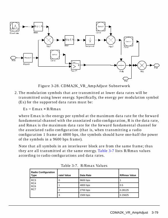
Figure 3-28. CDMA2K_VR_AmpAdjust Subnetwork
2. The modulation symbols that are transmitted at lower data rates will betransmitted using lower energy. Specifically, the energy per modulation symbol(Es) for the supported data rates must be:
Es = Emax × R/Rmax
where Emax is the energy per symbol at the maximum data rate for the forwardfundamental channel with the associated radio configuration, R is the data rate,and Rmax is the maximum data rate for the forward fundamental channel forthe associated radio configuration (that is, when transmitting a radioconfiguration 1 frame at 4800 bps, the symbols should have one-half the powerof the symbols in a 9600 bps frame).
Note that all symbols in an interleaver block are from the same frame; thusthey are all transmitted at the same energy. Table 3-7 lists R/Rmax valuesaccording to radio configurations and data rates.
Table 3-7. R/Rmax Values
Radio ConfigurationType rateI Value Data Rate R/Rmax Value
RC3RC4RC6RC7
0 9600 bps 1
1 4800 bps 0.5
2 2700 bps 0.28125
3 1500 bps 0.15625
CDMA2K_VR_AmpAdjust 3-79

Channel Coding Components
References
[1]TIA/EIA/IS-2000.2 (PN-4428), Physical Layer Standard for cdma2000 SpreadSpectrum Systems, July 1999.
Other 0 9600 or 14400 bps 1
1 4800 or 7200 bps 0.5
2 2400 or 3600 bps 0.25
3 1200 or 1800 bps 0.125
Table 3-7. R/Rmax Values
Radio ConfigurationType rateI Value Data Rate R/Rmax Value
3-80 CDMA2K_VR_AmpAdjust

CDMA2K_VR_CCwithTail
Description Variable data rate convolutional encoder with tailLibrary cdma2000, Channel CodingClass SDFCDMA2K_VR_CCwithTailDerived From CDMA2K_VR_CC
Parameters
Pin Inputs
Pin Outputs
Notes/Equations
1. This model is used to convolutionally encode variable data rate input frameswith tail bits for forward or reverse traffic channels.
Name Description Default Type
RadioConfig radio configuration: FwdRC1, Fwd RC2, Fwd RC3,Fwd RC4, Fwd RC5, FwdRC6, Fwd RC7, Fwd RC8,Fwd RC9, Rev RC1, RevRC2, Rev RC3, Rev RC4,Rev RC5, Rev RC6
Fwd RC1 enum
Pin Name Description Signal Type
1 D_in input data int
2 rateI data rate of input frame int
Pin Name Description Signal Type
3 D_out output data int
4 rateO data rate of output frame int
CDMA2K_VR_CCwithTail 3-81

Channel Coding Components
Each firing, N D_out tokens and one rateO token are produced when M D_intokens and one rateI token are consumed. (N and M are defined in Table 3-8.)
2. Convolutional encoder types for different radio configurations are listed inTable 3-8.
These rates are used:
• rate 1/2 K 9 g0 0753 g1 0561, rate 1/3 K 9 g0 0557 g1 0663 g2 0711
• rate 1/4 K 9 g0 0765 g1 0671 g2 0513 g3 0473
• rate 1/6 K 9 g0 0457 g1 0755 g2 0551 g3 0637 g4 0625 g5_0727
(rate means convolutional code rate, K means constraint length, g meansgenerator functions)
3. Information is transmitted at data rates listed in Table 3-9. To easilyimplement in the SDF domain, the full rate frame length is selected as thelength of block to be processed; padding bits are appended after the valid datafor lower data rate frames in order to keep the block length constant.
Table 3-8. Convolutional Type Used in Fundamental Channel
Radio Configuration CC TypeMaximum Input FrameLength (M)
Maximum Output FrameLength (N)
Reverse TrafficFundamental Channel
RC1 R=1/3 K=9 192 576
RC2 R=1/2 K=9 288 576
RC3, RC5 R=1/4 K=9 192 768
RC4, RC6 R=1/4 K=9 288 1152
Forward TrafficFundamental Channel
RC1, RC4 R=1/2 K=9 192 384
RC2, RC9 R=1/2 K=9 288 576
RC3 R=1/4 K=9 192 768
RC5, RC8 R=1/4 K=9 288 1152
RC6 R=1/6 K=9 192 1152
RC7 R=1/3 K=9 192 576
3-82 CDMA2K_VR_CCwithTail
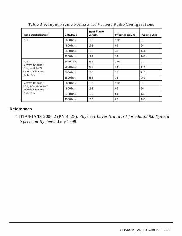
References
[1]TIA/EIA/IS-2000.2 (PN-4428), Physical Layer Standard for cdma2000 SpreadSpectrum Systems, July 1999.
Table 3-9. Input Frame Formats for Various Radio Configurations
Radio Configuration Data RateInput FrameLength Information Bits Padding Bits
RC1 9600 bps 192 192 0
4800 bps 192 96 96
2400 bps 192 48 144
1200 bps 192 24 168
RC2Forward Channel:RC5, RC8, RC9Reverse Channel:RC4, RC6
14400 bps 288 288 0
7200 bps 288 144 144
3600 bps 288 72 216
1800 bps 288 36 252
Forward Channel:RC3, RC4, RC6, RC7Reverse Channel:RC3, RC5
9600 bps 192 192 0
4800 bps 192 96 96
2700 bps 192 54 138
1500 bps 192 30 162
CDMA2K_VR_CCwithTail 3-83

Channel Coding Components
CDMA2K_VR_Coding
Description Variable Data Rate CoderLibrary cdma2000, Channel Coding
Parameters
Pin Inputs
Pin Outputs
Notes/Equations
1. This subnetwork is used to perform channel coding for radio configurations ofvariable data rate. Figure 3-29 shows the schematic for this subnetwork, whichincludes framing, convolutional encoder and frame rate matching. Interleavingis not included.
Name Description Default Type
RadioConfig radio configuration: FwdRC1, Fwd RC2, Fwd RC3,Fwd RC4, Fwd RC5, FwdRC6, Fwd RC7, Fwd RC8,Fwd RC9, Rev RC1, RevRC2, Rev RC3, Rev RC4,Rev RC5, Rev RC6
Fwd RC1 enum
Pin Name Description Signal Type
1 D_in input symbols int
2 ratel data rate of input frame int
Pin Name Description Signal Type
3 D_out output symbols real
4 rate0 data rate of output frame int
3-84 CDMA2K_VR_Coding
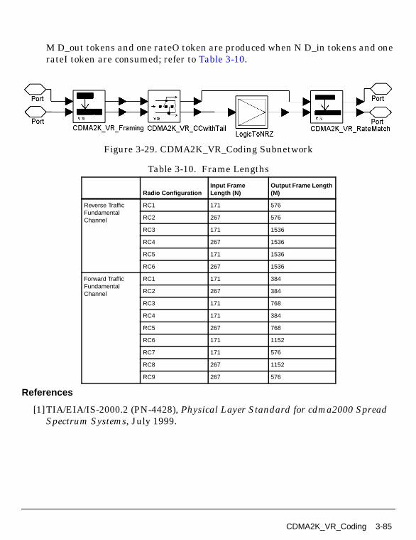
M D_out tokens and one rateO token are produced when N D_in tokens and onerateI token are consumed; refer to Table 3-10.
Figure 3-29. CDMA2K_VR_Coding Subnetwork
References
[1]TIA/EIA/IS-2000.2 (PN-4428), Physical Layer Standard for cdma2000 SpreadSpectrum Systems, July 1999.
Table 3-10. Frame Lengths
Radio ConfigurationInput FrameLength (N)
Output Frame Length(M)
Reverse TrafficFundamentalChannel
RC1 171 576
RC2 267 576
RC3 171 1536
RC4 267 1536
RC5 171 1536
RC6 267 1536
Forward TrafficFundamentalChannel
RC1 171 384
RC2 267 384
RC3 171 768
RC4 171 384
RC5 267 768
RC6 171 1152
RC7 171 576
RC8 267 1152
RC9 267 576
CDMA2K_VR_Coding 3-85
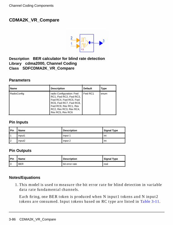
Channel Coding Components
CDMA2K_VR_Compare
Description BER calculator for blind rate detectionLibrary cdma2000, Channel CodingClass SDFCDMA2K_VR_Compare
Parameters
Pin Inputs
Pin Outputs
Notes/Equations
1. This model is used to measure the bit error rate for blind detection in variabledata rate fundamental channels.
Each firing, one BER token is produced when N input1 tokens and N input2tokens are consumed. Input tokens based on RC type are listed in Table 3-11.
Name Description Default Type
RadioConfig radio Configuration: FwdRC1, Fwd RC2, Fwd RC3,Fwd RC4, Fwd RC5, FwdRC6, Fwd RC7, Fwd RC8,Fwd RC9, Rev RC1, RevRC2, Rev RC3, Rev RC4,Rev RC5, Rev RC6
Fwd RC1 enum
Pin Name Description Signal Type
1 input1 input 1 int
2 input2 input 2 int
Pin Name Description Signal Type
3 BER bit error rate real
3-86 CDMA2K_VR_Compare
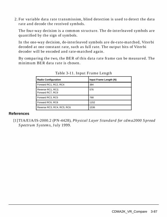
2. For variable data rate transmission, blind detection is used to detect the datarate and decode the received symbols.
The four-way decision is a common structure. The de-interleaved symbols arequantified by the sign of symbols.
In the one-way decision, de-interleaved symbols are de-rate-matched, Viterbidecoded at one constant rate, such as full rate. The output bits of Viterbidecoder will be encoded and rate-matched again.
By comparing the two, the BER of this data rate frame can be measured. Theminimum BER data rate is chosen.
References
[1]TIA/EIA/IS-2000.2 (PN-4428), Physical Layer Standard for cdma2000 SpreadSpectrum Systems, July 1999.
Table 3-11. Input Frame Length
Radio Configuration Input Frame Length (N)
Forward RC1, RC2, RC4 384
Reverse RC1, RC2;Forward RC7, RC9
576
Forward RC3, RC5 768
Forward RC6, RC8 1152
Reverse RC3, RC4, RC5, RC6 1536
CDMA2K_VR_Compare 3-87

Channel Coding Components
CDMA2K_VR_DCCwithTail
Description Variable data rate Viterbi decoder for convolutional code with tailLibrary cdma2000, Channel CodingClass SDFCDMA2K_VR_DCCwithTailDerived From CDMA2K_VR_Viterbi
Parameters
Pin Inputs
Pin Outputs
Notes/Equations
1. This model is used to decode variable data rate input symbols for forward orreverse traffic channels. The Viterbi decoding algorithm is same as thealgorithm used in CDMA2K_DCC_withTail.
Name Description Default Type
RadioConfig radio configuration: FwdRC1, Fwd RC2, Fwd RC3,Fwd RC4, Fwd RC5, FwdRC6, Fwd RC7, Fwd RC8,Fwd RC9, Rev RC1, RevRC2, Rev RC3, Rev RC4,Rev RC5, Rev RC6
Fwd RC1 enum
Pin Name Description Signal Type
1 D_in input data real
2 rateI data rate of input frame int
Pin Name Description Signal Type
3 D_out output data int
4 rateO data rate of output frame int
3-88 CDMA2K_VR_DCCwithTail
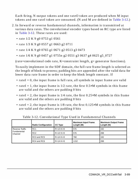
Each firing, N output tokens and one rateO token are produced when M inputtokens and one rateI token are consumed. (N and M are defined in Table 3-12.)
2. In forward or reverse fundamental channels, information is transmitted atvarious data rates. The convolutional encoder types based on RC type are listedin Table 3-12. These rates are used:
• rate 1/2 K 9 g0 0753 g1 0561
• rate 1/3 K 9 g0 0557 g1 0663 g2 0711
• rate 1/4 K 9 g0 0765 g1 0671 g2 0513 g3 0473
• rate 1/6 K 9 g0 0457 g1 0755n g2 0551 g3 0637 g4 0625 g5_0727
(rate=convolutional code rate, K=constraint length, g= generator functions).
To easily implement in the SDF domain, the full rate frame length is selected asthe length of block to process; padding bits are appended after the valid data forlower data rate frame in order to keep the block length constant. If
• rateI = 0, the input frame is full rate, all symbols in input frame are valid
• rateI = 1, the input frame is 1/2 rate, the first 0.5×M symbols in this frameare valid and the others are padding 0 bits
• rateI = 2, the input frame is 1/4 rate, the first 0.25×M symbols in this frameare valid and the others are padding 0 bits
• rateI = 2, the input frame is 1/8 rate, the first 0.125×M symbols in this frameare valid and the others are padding 0 bits
Table 3-12. Convolutional Type Used in Fundamental Channels
Radio Configuration CC TypeMaximum Input FrameLength (M)
Maximum Output FrameLength (N)
Reverse TrafficFundamentalChannel
RC1 R=1/3 K=9 576 192
RC2 R=1/2 K=9 576 288
RC3 and RC5 R=1/4 K=9 768 192
RC4 and RC6 R=1/4 K=9 1152 288
CDMA2K_VR_DCCwithTail 3-89
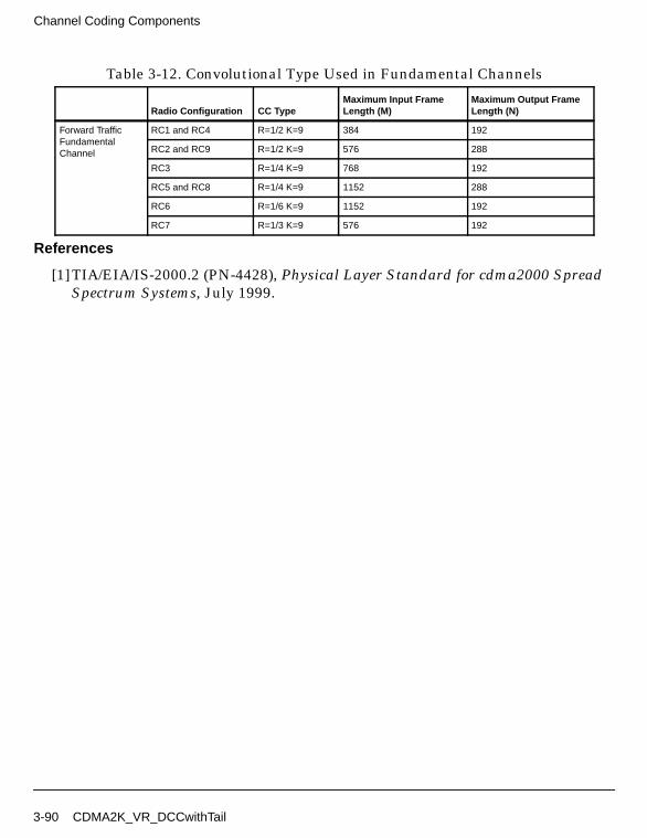
Channel Coding Components
References
[1]TIA/EIA/IS-2000.2 (PN-4428), Physical Layer Standard for cdma2000 SpreadSpectrum Systems, July 1999.
Forward TrafficFundamentalChannel
RC1 and RC4 R=1/2 K=9 384 192
RC2 and RC9 R=1/2 K=9 576 288
RC3 R=1/4 K=9 768 192
RC5 and RC8 R=1/4 K=9 1152 288
RC6 R=1/6 K=9 1152 192
RC7 R=1/3 K=9 576 192
Table 3-12. Convolutional Type Used in Fundamental Channels
Radio Configuration CC TypeMaximum Input FrameLength (M)
Maximum Output FrameLength (N)
3-90 CDMA2K_VR_DCCwithTail
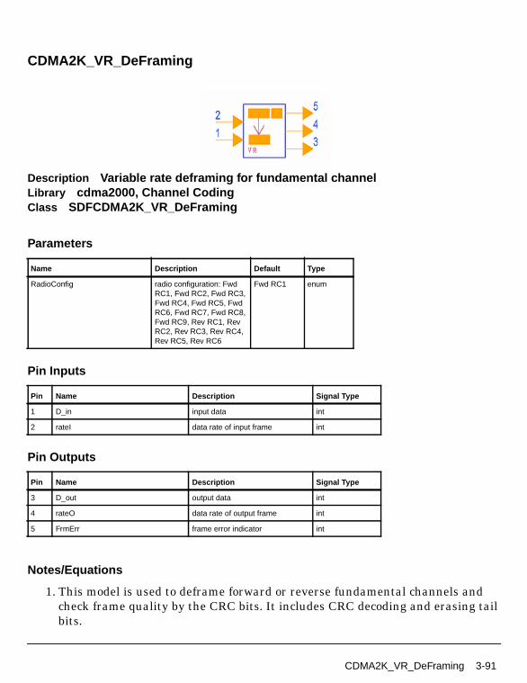
CDMA2K_VR_DeFraming
Description Variable rate deframing for fundamental channelLibrary cdma2000, Channel CodingClass SDFCDMA2K_VR_DeFraming
Parameters
Pin Inputs
Pin Outputs
Notes/Equations
1. This model is used to deframe forward or reverse fundamental channels andcheck frame quality by the CRC bits. It includes CRC decoding and erasing tailbits.
Name Description Default Type
RadioConfig radio configuration: FwdRC1, Fwd RC2, Fwd RC3,Fwd RC4, Fwd RC5, FwdRC6, Fwd RC7, Fwd RC8,Fwd RC9, Rev RC1, RevRC2, Rev RC3, Rev RC4,Rev RC5, Rev RC6
Fwd RC1 enum
Pin Name Description Signal Type
1 D_in input data int
2 rateI data rate of input frame int
Pin Name Description Signal Type
3 D_out output data int
4 rateO data rate of output frame int
5 FrmErr frame error indicator int
CDMA2K_VR_DeFraming 3-91
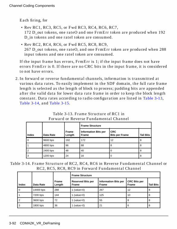
Channel Coding Components
Each firing, for
• Rev RC1, RC3, RC5, or Fwd RC3, RC4, RC6, RC7,172 D_out tokens, one rateO and one FrmErr token are produced when 192D_in tokens and one rateI token are consumed.
• Rev RC2, RC4, RC6, or Fwd RC5, RC8, RC9,267 D_out tokens, one rateO, and one FrmErr token are produced when 288input tokens and one rateI token are consumed.
If the input frame has errors, FrmErr is 1; if the input frame does not haveerrors FrmErr is 0. If there are no CRC bits in the input frame, it is consideredto not have errors.
2. In forward or reverse fundamental channels, information is transmitted atvarious data rates. To easily implement in the SDF domain, the full rate framelength is selected as the length of block to process; padding bits are appendedafter the valid data for lower data rate frame in order to keep the block lengthconstant. Data rates according to radio configuration are listed in Table 3-13,Table 3-14, and Table 3-15.
Table 3-13. Frame Structure of RC1 inForward or Reverse Fundamental Channel
Index Data RateFrameLength
Frame Structure
Information Bits perFrame
CRCBits per Frame Tail Bits
0 9600 bps 192 172 12 8
1 4800 bps 96 88 8 8
2 2400 bps 48 40 0 8
3 1200 bps 24 16 0 8
Table 3-14. Frame Structure of RC2, RC4, RC6 in Reverse Fundamental Channel orRC2, RC5, RC8, RC9 in Forward Fundamental Channel
Index Data RateFrameLength
Frame Structure
Reserved Bits perFrame
Information Bits perFrame
CRC Bits perFrame Tail Bits
0 14400 bps 288 1 (value=0) 267 12 8
1 7200 bps 144 1 (value=0) 125 10 8
2 3600 bps 72 1 (value=0) 55 8 8
3 1800 bps 36 1 (value=0) 21 6 8
3-92 CDMA2K_VR_DeFraming

References
[1]TIA/EIA/IS-2000.2 (PN-4428), Physical Layer Standard for cdma2000 SpreadSpectrum Systems, July 1999.
Table 3-15. Frame Structure of RC3, RC5 in Reverse Fundamental Channel orRC3, RC4, RC6, RC7 in Forward Fundamental Channel
Index Data RateFrameLength
Frame Structure
Information Bits perFrame
CRCBits per Frame
TailBits
0 9600 bps 192 172 12 8
1 4800 bps 96 88 8 8
2 2700 bps 54 40 6 8
3 1500 bps 30 16 6 8
CDMA2K_VR_DeFraming 3-93

Channel Coding Components
CDMA2K_VR_Framing
Description Variable rate framing for fundamental channelLibrary cdma2000, Channel CodingClass SDFCDMA2K_VR_Framing
Parameters
Pin Inputs
Pin Outputs
Notes/Equations
1. This model is used to frame forward or reverse fundamental channels. Itincludes CRC coder and adding 8 bits tail.
Each firing, for
Name Description Default Type
RadioConfig radio configuration: FwdRC1, Fwd RC2, Fwd RC3,Fwd RC4, Fwd RC5, FwdRC6, Fwd RC7, Fwd RC8,Fwd RC9, Rev RC1, RevRC2, Rev RC3, Rev RC4,Rev RC5, Rev RC6
Fwd RC1 enum
Pin Name Description Signal Type
1 D_in input data int
2 rateI data rate of input frame int
Pin Name Description Signal Type
3 D_out output data int
4 rateO data rate of output frame int
3-94 CDMA2K_VR_Framing
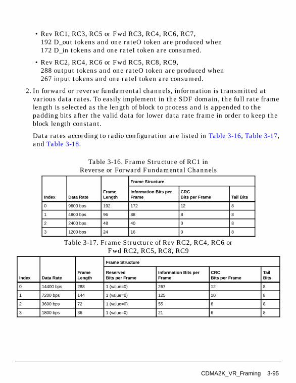
• Rev RC1, RC3, RC5 or Fwd RC3, RC4, RC6, RC7,192 D_out tokens and one rateO token are produced when172 D_in tokens and one rateI token are consumed.
• Rev RC2, RC4, RC6 or Fwd RC5, RC8, RC9,288 output tokens and one rateO token are produced when267 input tokens and one rateI token are consumed.
2. In forward or reverse fundamental channels, information is transmitted atvarious data rates. To easily implement in the SDF domain, the full rate framelength is selected as the length of block to process and is appended to thepadding bits after the valid data for lower data rate frame in order to keep theblock length constant.
Data rates according to radio configuration are listed in Table 3-16, Table 3-17,and Table 3-18.
Table 3-16. Frame Structure of RC1 inReverse or Forward Fundamental Channels
Index Data RateFrameLength
Frame Structure
Information Bits perFrame
CRCBits per Frame Tail Bits
0 9600 bps 192 172 12 8
1 4800 bps 96 88 8 8
2 2400 bps 48 40 0 8
3 1200 bps 24 16 0 8
Table 3-17. Frame Structure of Rev RC2, RC4, RC6 orFwd RC2, RC5, RC8, RC9
Index Data RateFrameLength
Frame Structure
ReservedBits per Frame
Information Bits perFrame
CRCBits per Frame
TailBits
0 14400 bps 288 1 (value=0) 267 12 8
1 7200 bps 144 1 (value=0) 125 10 8
2 3600 bps 72 1 (value=0) 55 8 8
3 1800 bps 36 1 (value=0) 21 6 8
CDMA2K_VR_Framing 3-95
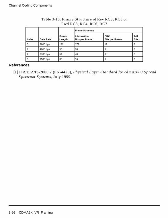
Channel Coding Components
References
[1]TIA/EIA/IS-2000.2 (PN-4428), Physical Layer Standard for cdma2000 SpreadSpectrum Systems, July 1999.
Table 3-18. Frame Structure of Rev RC3, RC5 orFwd RC3, RC4, RC6, RC7
Index Data RateFrameLength
Frame Structure
InformationBits per Frame
CRCBits per Frame
TailBits
0 9600 bps 192 172 12 8
1 4800 bps 96 88 8 8
2 2700 bps 54 40 6 8
3 1500 bps 30 16 6 8
3-96 CDMA2K_VR_Framing
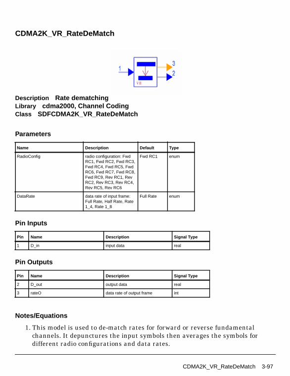
CDMA2K_VR_RateDeMatch
Description Rate dematchingLibrary cdma2000, Channel CodingClass SDFCDMA2K_VR_RateDeMatch
Parameters
Pin Inputs
Pin Outputs
Notes/Equations
1. This model is used to de-match rates for forward or reverse fundamentalchannels. It depunctures the input symbols then averages the symbols fordifferent radio configurations and data rates.
Name Description Default Type
RadioConfig radio configuration: FwdRC1, Fwd RC2, Fwd RC3,Fwd RC4, Fwd RC5, FwdRC6, Fwd RC7, Fwd RC8,Fwd RC9, Rev RC1, RevRC2, Rev RC3, Rev RC4,Rev RC5, Rev RC6
Fwd RC1 enum
DataRate data rate of input frame:Full Rate, Half Rate, Rate1_4, Rate 1_8
Full Rate enum
Pin Name Description Signal Type
1 D_in input data real
Pin Name Description Signal Type
2 D_out output data real
3 rateO data rate of output frame int
CDMA2K_VR_RateDeMatch 3-97

Channel Coding Components
M D_out tokens and one rateO token are produced when N D_in tokens areconsumed. (Table 3-19 and Table 3-20 show radio configurations and input andoutput tokens for forward and reverse fundamental channels. Input framelength = M and output frame length = N.)
2. In forward or reverse fundamental channels, information is transmitted atvarious data rates. To easily implement in the SDF domain, the full rate framelength is selected as the length of block to process; padding bits are appendedafter the valid data for lower data rate frame in order to keep the block lengthconstant. Table 3-19 and Table 3-20 show rate de-matching of radioconfigurations for forward and reverse traffic fundamental channels.
Table 3-19. Rate De-Matching of Radio Configurations inForward Fundamental Channel
RadioConfig.
DataRate(bps)
OutputFrameLength
Information Bits inOutput Frame
Padding Bits inOutput Frame
RepetitionFactor
PunctureDeletion
InputFrameLength
RC1 9600 384 384 0 1 None 384
4800 384 192 192 2 None
2400 384 96 288 4 None
1200 384 48 336 8 None
RC2 14400 576 576 0 1 2 of 6 384
7200 576 288 288 2 2 of 6
3600 576 144 432 4 2 of 6
1800 576 72 504 8 2 of 6
RC3 9600 768 768 0 1 None 768
4800 768 384 384 2 None
2700 768 216 552 4 1 of 9
1500 768 120 648 8 1 of 5
RC4 9600 384 384 0 1 None 384
4800 384 192 192 2 None
2700 384 108 276 4 1 of 9
1500 384 60 324 8 1 of 5
RC5 14400 1152 1152 0 1 4 of 12 768
7200 1152 576 576 2 4 of 12
3600 1152 288 864 4 4 of 12
1800 1152 144 1008 8 4 of 12
3-98 CDMA2K_VR_RateDeMatch
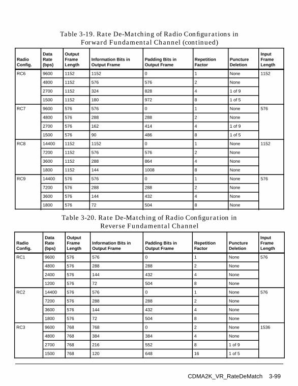
RC6 9600 1152 1152 0 1 None 1152
4800 1152 576 576 2 None
2700 1152 324 828 4 1 of 9
1500 1152 180 972 8 1 of 5
RC7 9600 576 576 0 1 None 576
4800 576 288 288 2 None
2700 576 162 414 4 1 of 9
1500 576 90 486 8 1 of 5
RC8 14400 1152 1152 0 1 None 1152
7200 1152 576 576 2 None
3600 1152 288 864 4 None
1800 1152 144 1008 8 None
RC9 14400 576 576 0 1 None 576
7200 576 288 288 2 None
3600 576 144 432 4 None
1800 576 72 504 8 None
Table 3-20. Rate De-Matching of Radio Configuration inReverse Fundamental Channel
RadioConfig.
DataRate(bps)
OutputFrameLength
Information Bits inOutput Frame
Padding Bits inOutput Frame
RepetitionFactor
PunctureDeletion
InputFrameLength
RC1 9600 576 576 0 1 None 576
4800 576 288 288 2 None
2400 576 144 432 4 None
1200 576 72 504 8 None
RC2 14400 576 576 0 1 None 576
7200 576 288 288 2 None
3600 576 144 432 4 None
1800 576 72 504 8 None
RC3 9600 768 768 0 2 None 1536
4800 768 384 384 4 None
2700 768 216 552 8 1 of 9
1500 768 120 648 16 1 of 5
Table 3-19. Rate De-Matching of Radio Configurations inForward Fundamental Channel (continued)
RadioConfig.
DataRate(bps)
OutputFrameLength
Information Bits inOutput Frame
Padding Bits inOutput Frame
RepetitionFactor
PunctureDeletion
InputFrameLength
CDMA2K_VR_RateDeMatch 3-99

Channel Coding Components
References
[1]TIA/EIA/IS-2000.2 (PN-4428), Physical Layer Standard for cdma2000 SpreadSpectrum Systems, July 1999.
RC4 14400 1152 1152 0 2 8 of 24 1536
7200 1152 576 576 4 8 of 24
3600 1152 288 864 8 8 of 24
1800 1152 144 1008 16 8 of 24
RC5 9600 768 768 0 2 None 1536
4800 768 384 384 4 None
2700 768 216 552 8 1 of 9
1500 768 120 648 16 1 of 5
RC6 14400 1152 1152 0 2 8 of 24 1536
7200 1152 576 576 4 8 of 24
3600 1152 288 864 8 8 of 24
1800 1152 144 1008 16 8 of 24
Table 3-20. Rate De-Matching of Radio Configuration inReverse Fundamental Channel (continued)
RadioConfig.
DataRate(bps)
OutputFrameLength
Information Bits inOutput Frame
Padding Bits inOutput Frame
RepetitionFactor
PunctureDeletion
InputFrameLength
3-100 CDMA2K_VR_RateDeMatch
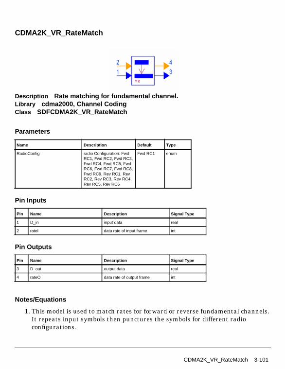
CDMA2K_VR_RateMatch
Description Rate matching for fundamental channel.Library cdma2000, Channel CodingClass SDFCDMA2K_VR_RateMatch
Parameters
Pin Inputs
Pin Outputs
Notes/Equations
1. This model is used to match rates for forward or reverse fundamental channels.It repeats input symbols then punctures the symbols for different radioconfigurations.
Name Description Default Type
RadioConfig radio Configuration: FwdRC1, Fwd RC2, Fwd RC3,Fwd RC4, Fwd RC5, FwdRC6, Fwd RC7, Fwd RC8,Fwd RC9, Rev RC1, RevRC2, Rev RC3, Rev RC4,Rev RC5, Rev RC6
Fwd RC1 enum
Pin Name Description Signal Type
1 D_in input data real
2 rateI data rate of input frame int
Pin Name Description Signal Type
3 D_out output data real
4 rateO data rate of output frame int
CDMA2K_VR_RateMatch 3-101
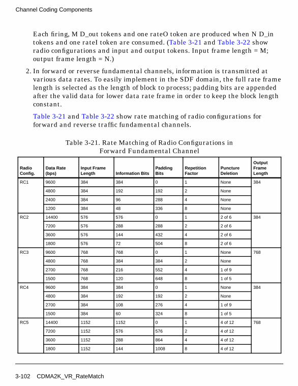
Channel Coding Components
Each firing, M D_out tokens and one rateO token are produced when N D_intokens and one rateI token are consumed. (Table 3-21 and Table 3-22 showradio configurations and input and output tokens. Input frame length = M;output frame length = N.)
2. In forward or reverse fundamental channels, information is transmitted atvarious data rates. To easily implement in the SDF domain, the full rate framelength is selected as the length of block to process; padding bits are appendedafter the valid data for lower data rate frame in order to keep the block lengthconstant.
Table 3-21 and Table 3-22 show rate matching of radio configurations forforward and reverse traffic fundamental channels.
Table 3-21. Rate Matching of Radio Configurations inForward Fundamental Channel
RadioConfig.
Data Rate(bps)
Input FrameLength Information Bits
PaddingBits
RepetitionFactor
PunctureDeletion
OutputFrameLength
RC1 9600 384 384 0 1 None 384
4800 384 192 192 2 None
2400 384 96 288 4 None
1200 384 48 336 8 None
RC2 14400 576 576 0 1 2 of 6 384
7200 576 288 288 2 2 of 6
3600 576 144 432 4 2 of 6
1800 576 72 504 8 2 of 6
RC3 9600 768 768 0 1 None 768
4800 768 384 384 2 None
2700 768 216 552 4 1 of 9
1500 768 120 648 8 1 of 5
RC4 9600 384 384 0 1 None 384
4800 384 192 192 2 None
2700 384 108 276 4 1 of 9
1500 384 60 324 8 1 of 5
RC5 14400 1152 1152 0 1 4 of 12 768
7200 1152 576 576 2 4 of 12
3600 1152 288 864 4 4 of 12
1800 1152 144 1008 8 4 of 12
3-102 CDMA2K_VR_RateMatch

RC6 9600 1152 1152 0 1 None 1152
4800 1152 576 576 2 None
2700 1152 324 828 4 1 of 9
1500 1152 180 972 8 1 of 5
RC7 9600 576 576 0 1 None 576
4800 576 288 288 2 None
2700 576 162 414 4 1 of 9
1500 576 90 486 8 1 of 5
RC8 14400 1152 1152 0 1 None 1152
7200 1152 576 576 2 None
3600 1152 288 864 4 None
1800 1152 144 1008 8 None
RC9 14400 576 576 0 1 None 576
7200 576 288 288 2 None
3600 576 144 432 4 None
1800 576 72 504 8 None
Table 3-22. Rate Matching of Radio Configurations inReverse Fundamental Channel
RadioConfig.
Data Rate(bps)
InputFrameLength Information Bits
PaddingBits
RepetitionFactor
PunctureDeletion
OutputFrameLength
RC1 9600 576 576 0 1 None 576
4800 576 288 288 2 None
2400 576 144 432 4 None
1200 576 72 504 8 None
RC2 14400 576 576 0 1 None 576
7200 576 288 288 2 None
3600 576 144 432 4 None
1800 576 72 504 8 None
RC3 9600 768 768 0 2 None 1536
4800 768 384 384 4 None
2700 768 216 552 8 1 of 9
1500 768 120 648 16 1 of 5
Table 3-21. Rate Matching of Radio Configurations inForward Fundamental Channel (continued)
RadioConfig.
Data Rate(bps)
Input FrameLength Information Bits
PaddingBits
RepetitionFactor
PunctureDeletion
OutputFrameLength
CDMA2K_VR_RateMatch 3-103
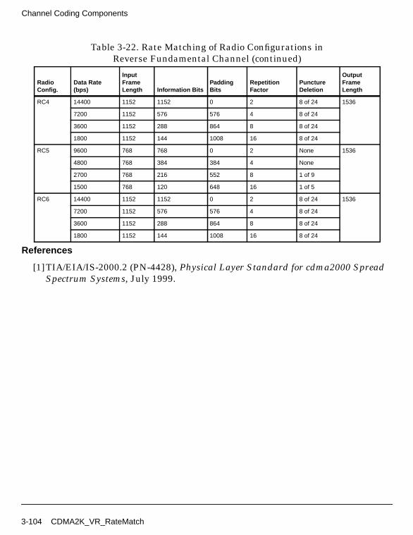
Channel Coding Components
References
[1]TIA/EIA/IS-2000.2 (PN-4428), Physical Layer Standard for cdma2000 SpreadSpectrum Systems, July 1999.
RC4 14400 1152 1152 0 2 8 of 24 1536
7200 1152 576 576 4 8 of 24
3600 1152 288 864 8 8 of 24
1800 1152 144 1008 16 8 of 24
RC5 9600 768 768 0 2 None 1536
4800 768 384 384 4 None
2700 768 216 552 8 1 of 9
1500 768 120 648 16 1 of 5
RC6 14400 1152 1152 0 2 8 of 24 1536
7200 1152 576 576 4 8 of 24
3600 1152 288 864 8 8 of 24
1800 1152 144 1008 16 8 of 24
Table 3-22. Rate Matching of Radio Configurations inReverse Fundamental Channel (continued)
RadioConfig.
Data Rate(bps)
InputFrameLength Information Bits
PaddingBits
RepetitionFactor
PunctureDeletion
OutputFrameLength
3-104 CDMA2K_VR_RateMatch
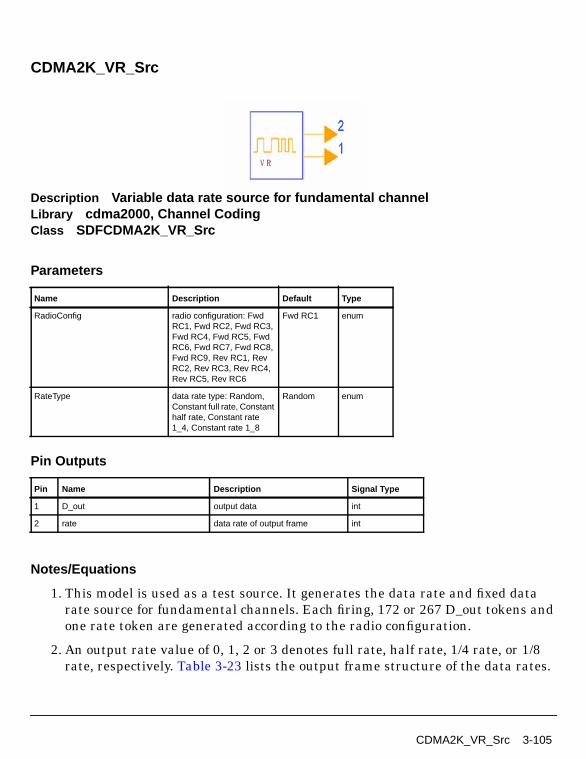
CDMA2K_VR_Src
Description Variable data rate source for fundamental channelLibrary cdma2000, Channel CodingClass SDFCDMA2K_VR_Src
Parameters
Pin Outputs
Notes/Equations
1. This model is used as a test source. It generates the data rate and fixed datarate source for fundamental channels. Each firing, 172 or 267 D_out tokens andone rate token are generated according to the radio configuration.
2. An output rate value of 0, 1, 2 or 3 denotes full rate, half rate, 1/4 rate, or 1/8rate, respectively. Table 3-23 lists the output frame structure of the data rates.
Name Description Default Type
RadioConfig radio configuration: FwdRC1, Fwd RC2, Fwd RC3,Fwd RC4, Fwd RC5, FwdRC6, Fwd RC7, Fwd RC8,Fwd RC9, Rev RC1, RevRC2, Rev RC3, Rev RC4,Rev RC5, Rev RC6
Fwd RC1 enum
RateType data rate type: Random,Constant full rate, Constanthalf rate, Constant rate1_4, Constant rate 1_8
Random enum
Pin Name Description Signal Type
1 D_out output data int
2 rate data rate of output frame int
CDMA2K_VR_Src 3-105
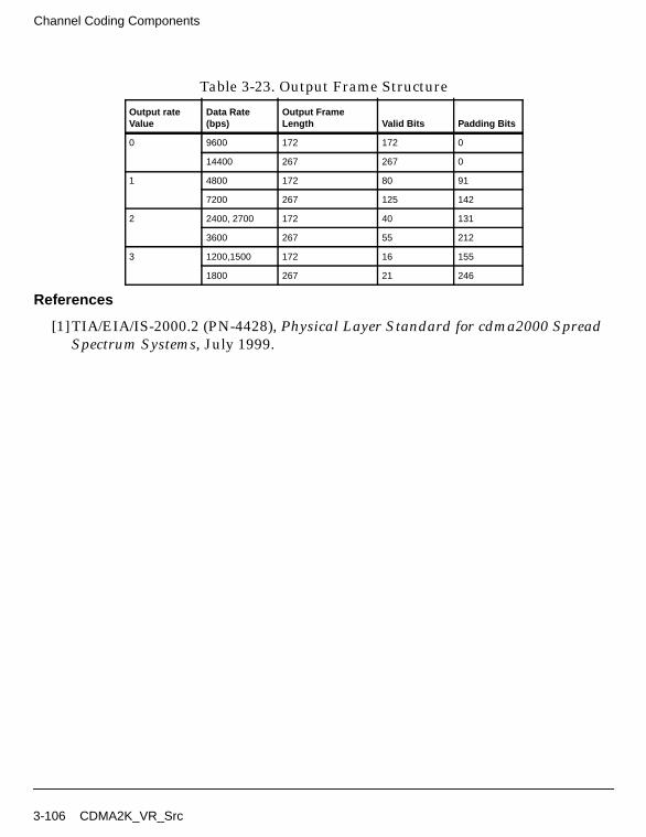
Channel Coding Components
References
[1]TIA/EIA/IS-2000.2 (PN-4428), Physical Layer Standard for cdma2000 SpreadSpectrum Systems, July 1999.
Table 3-23. Output Frame Structure
Output rateValue
Data Rate(bps)
Output FrameLength Valid Bits Padding Bits
0 9600 172 172 0
14400 267 267 0
1 4800 172 80 91
7200 267 125 142
2 2400, 2700 172 40 131
3600 267 55 212
3 1200,1500 172 16 155
1800 267 21 246
3-106 CDMA2K_VR_Src

Chapter 4: Receivers
4-1

Receivers
CDMA2K_CarrierFreqEstimate
Description Phase Estimator for Carrier FrequencyLibrary cdma2000, Receivers
Parameters
Name Description Default Type Range
Link type of link: Forward link,Reverse link
Forward link enum
PhaseDetectRate phase detection rate:PD3200, PD6400,PD9600, PD12800
PD3200 enum †
SpreadRate PN chip rate, multiple of1.2288Mcps: SR1, SR3
SR1 enum
SampleRate number of samples perchip
4 int [1, 32] † †
G1 parameter to determinefirst lowpass filter gain
0.00036 real (0, 0.0022]
G2 parameter to determinesecond lowpass filter gain
0.000025 real (0, 0.002]
EstimateWindow window size for estimatingchannel coefficients interms of symbol (usedwhen Link=Forward link)
6 int [1, 50]
WalshLength Walsh code length usedfor spreading (used whenLink=Forward link)
64 int [1, 256]
† When PhaseDetectRate is PD3200, PD6400, PD9600, PD12800, M is 1, 2, 3, 4, respectively, which is the gain ofphase detector. G1 and G2 will be adjusted during applications.
††SampleRate is defined as 4 in the cdma2000 standard.
4-2

Pin Inputs
Pin Outputs
Notes/Equations
1. This subnetwork is used to estimate carrier frequency. It is a part of theautomatic frequency control loop and includes a phase detector, lowpass filter,and numeric control oscillator. The input signal is received from the pilot signalafter despreading and maximal ratio combination.
Figure 4-1 shows the schematic for this subnetwork.
Figure 4-1. CDMA2K_CarrierFreqEstimate Subnetwork
References
[1]L. Yan, “Research of Synchronization technique in Direction Sequence SpreadSpectrum Communication System” (Ph.D. dissertation, March 1998).
Pin Name Description Signal Type
1 Pbit pilot and power control bits int
2 SigIn input signal complex
Pin Name Description Signal Type
3 Phase phase offset complex
CDMA2K_CarrierFreqEstimate 4-3
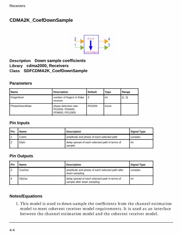
Receivers
CDMA2K_CoefDownSample
Description Down sample coefficientsLibrary cdma2000, ReceiversClass SDFCDMA2K_CoefDownSample
Parameters
Pin Inputs
Pin Outputs
Notes/Equations
1. This model is used to down-sample the coefficients from the channel estimationmodel to meet coherent receiver model requirements. It is used as an interfacebetween the channel estimation model and the coherent receiver model.
Name Description Default Type Range
FingerNum number of fingers in Rakereceiver
3 int [1, 5]
PhaseDetectRate phase detection rate:PD3200, PD6400,PD9600, PD12800
PD3200 enum
Pin Name Description Signal Type
1 CoeIn amplitude and phase of each selected path complex
2 DlyIn delay spread of each selected path in terms ofsample
int
Pin Name Description Signal Type
3 CoeOut amplitude and phase of each selected path afterdown sampling
complex
4 DlyOut delay spread of each selected path in terms ofsample after down sampling
int
4-4

Each firing, FingerNum CoeOut and DlyOut tokens are produced whenFingerNum×M CoeIn and DlyIn tokens are consumed. When
PhaseDetectRate=PD3200, M=1PhaseDetectRate=PD6400, M=2PhaseDetectRate=PD9600, M=3PhaseDetectRate=PD12800, M=4.
References
[1]TIA/EIA/IS-2000.2 (PN-4428), Physical Layer Standard for cdma2000 SpreadSpectrum Systems, July, 1999.
CDMA2K_CoefDownSample 4-5
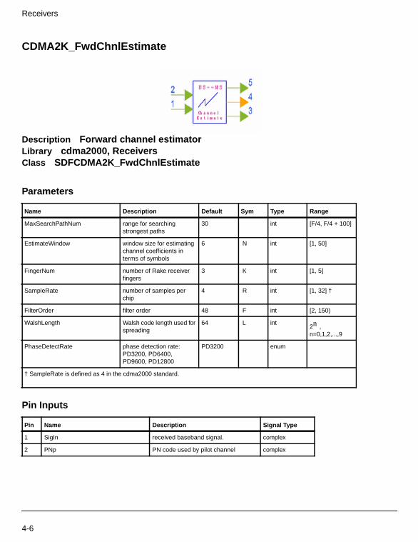
Receivers
CDMA2K_FwdChnlEstimate
Description Forward channel estimatorLibrary cdma2000, ReceiversClass SDFCDMA2K_FwdChnlEstimate
Parameters
Pin Inputs
Name Description Default Sym Type Range
MaxSearchPathNum range for searchingstrongest paths
30 int [F/4, F/4 + 100]
EstimateWindow window size for estimatingchannel coefficients interms of symbols
6 N int [1, 50]
FingerNum number of Rake receiverfingers
3 K int [1, 5]
SampleRate number of samples perchip
4 R int [1, 32] †
FilterOrder filter order 48 F int [2, 150)
WalshLength Walsh code length used forspreading
64 L int2n ,n=0,1,2,...,9
PhaseDetectRate phase detection rate:PD3200, PD6400,PD9600, PD12800
PD3200 enum
† SampleRate is defined as 4 in the cdma2000 standard.
Pin Name Description Signal Type
1 SigIn received baseband signal. complex
2 PNp PN code used by pilot channel complex
4-6
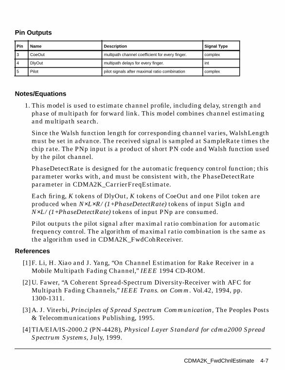
Pin Outputs
Notes/Equations
1. This model is used to estimate channel profile, including delay, strength andphase of multipath for forward link. This model combines channel estimatingand multipath search.
Since the Walsh function length for corresponding channel varies, WalshLengthmust be set in advance. The received signal is sampled at SampleRate times thechip rate. The PNp input is a product of short PN code and Walsh function usedby the pilot channel.
PhaseDetectRate is designed for the automatic frequency control function; thisparameter works with, and must be consistent with, the PhaseDetectRateparameter in CDMA2K_CarrierFreqEstimate.
Each firing, K tokens of DlyOut, K tokens of CoeOut and one Pilot token areproduced when N×L×R/(1+PhaseDetectRate) tokens of input SigIn andN×L/(1+PhaseDetectRate) tokens of input PNp are consumed.
Pilot outputs the pilot signal after maximal ratio combination for automaticfrequency control. The algorithm of maximal ratio combination is the same asthe algorithm used in CDMA2K_FwdCohReceiver.
References
[1]F. Li, H. Xiao and J. Yang, “On Channel Estimation for Rake Receiver in aMobile Multipath Fading Channel,” IEEE 1994 CD-ROM.
[2] U. Fawer, “A Coherent Spread-Spectrum Diversity-Receiver with AFC forMultipath Fading Channels,” IEEE Trans. on Comm. Vol.42, 1994, pp.1300-1311.
[3] A. J. Viterbi, Principles of Spread Spectrum Communication, The Peoples Posts& Telecommunications Publishing, 1995.
[4] TIA/EIA/IS-2000.2 (PN-4428), Physical Layer Standard for cdma2000 SpreadSpectrum Systems, July, 1999.
Pin Name Description Signal Type
3 CoeOut multipath channel coefficient for every finger. complex
4 DlyOut multipath delays for every finger. int
5 Pilot pilot signals after maximal ratio combination complex
CDMA2K_FwdChnlEstimate 4-7

Receivers
CDMA2K_FwdCohReceiver
Description Forward coherent combinerLibrary cdma2000, ReceiversClass SDFCDMA2K_FwdCohReceiver
Parameters
Pin Inputs
Pin Outputs
Name Description Default Sym Type Range
EstimateWindow window size for estimatingchannel coefficients interms of symbols
6 N int [1, 50]
FingerNum number of Rake receiverfingers
3 K int [1, 5]
SampleRate number of samples perchip
4 R int [1, 32] †
FilterOrder filter order 48 int [2, 150)
WalshLength Walsh code length used forspreading
64 L int2n ,n=0,1,2,...,9
† SampleRate is defined as 4 in the cdma2000 standard.
Pin Name Description Signal Type
1 SigIn input received signal. complex
2 PN input complex PN code used by correspondingchannel
complex
3 CoeIn input multipath channel coefficients complex
4 DlyIn input multipath delays int
Pin Name Description Signal Type
5 SigOut output signals complex
4-8
Notes/Equations
1. This model is used to implement coherent receiving with maximal ratiocombining. The necessary coefficients for rake combining, such as multipathdelay, channel phase, and attenuation are from the channel estimate model. Allparameters of this model must be consistent with CDMA2K_FwdChnlEstimate.
Each firing, N output tokens of SigOut are produced when N×L×R tokens ofinput SigIn, N×L tokens of input PN, K tokens of DlyIn, K tokens of CoeIn areconsumed.
References
[1]F. Li, H. Xiao and J. Yang, “On Channel Estimation for Rake Receiver in aMobile Multipath Fading Channel,” IEEE 1994 CD-ROM.
[2] U. Fawer, “A Coherent Spread-Spectrum Diversity-Receiver with AFC forMultipath Fading Channels,” IEEE Trans. on Comm. Vol.42, 1994, pp.1300-1311.
[3] A. J. Viterbi, Principles of Spread Spectrum Communication, The Peoples Posts& Telecommunications Publishing, 1995.
[4] TIA/EIA/IS-2000.2 (PN-4428), Physical Layer Standard for cdma2000 SpreadSpectrum Systems, July, 1999.
CDMA2K_FwdCohReceiver 4-9
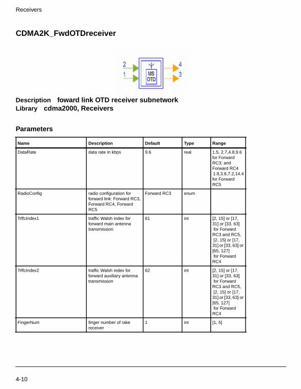
Receivers
CDMA2K_FwdOTDreceiver
Description foward link OTD receiver subnetworkLibrary cdma2000, Receivers
Parameters
Name Description Default Type Range
DataRate data rate in kbps 9.6 real 1.5, 2.7,4.8,9.6for ForwardRC3; andForward RC41.8,3.6,7.2,14.4for ForwardRC5
RadioConfig radio configuration forforward link: Forward RC3,Forward RC4, ForwardRC5
Forward RC3 enum
TrffcIndex1 traffic Walsh index forforward main antennatransmission
61 int [2, 15] or [17,31] or [33, 63] for ForwardRC3 and RC5, [2, 15] or [17,31] or [33, 63] or[65, 127] for ForwardRC4
TrffcIndex2 traffic Walsh index forforward auxiliary antennatransmission
62 int [2, 15] or [17,31] or [33, 63] for ForwardRC3 and RC5, [2, 15] or [17,31] or [33, 63] or[65, 127] for ForwardRC4
FingerNum finger number of rakereceiver
1 int [1, 5]
4-10

Pin Inputs
Pin Outputs
Notes/Equations
1. The subnetwork provides forward link receiver for OTD mode. The schematic isshown in Figure 4-2.
Figure 4-2. CDMA2K_FwdOTDreceiver Subnetwork
OuterLoop outer loop power controlenable: ENABLE,DISABLE
DISABLE enum
SIR_Threshold signal-to-interference ratiorequired
0 real (-∞, ∞)
Pin Name Description Signal Type
1 In1 input data from the main antenna complex
2 In2 input data from the auxiliary antenna complex
Pin Name Description Signal Type
3 Out output data int
4 PCB power control bits int
Name Description Default Type Range
CDMA2K_FwdOTDreceiver 4-11

Receivers
References
[1]3GPP2 C.S0002_A_1, “Physical Layer Standard for cdma2000 Spread SpectrumSystems Release A-Addendum 1,” Oct. 27, 2000
4-12 CDMA2K_FwdOTDreceiver

CDMA2K_FwdRake
Description Forward Rake ReceiverLibrary cdma2000, Receivers
Parameters
Pin Inputs
Pin Outputs
Name Description Default Sym Type Range
SpreadRate PN chip rate, multiple of1.2288 Mcps: SR1, SR3
SR1 SR enum
PilotWalshLen Walsh code length for pilotchannel (longer than trafficchannel))
128 int2n , n=1,2,...,9†
TrafficWalshLen Walsh code length fortraffic channel
64 int2n , n=1,2,...,9
FrameLength frame length of outputcomplex signals
192 L int [1, ∞)
FingerNum number of fingers in Rakereceiver
3 K int [1, 5]
† In general, the Walsh code used by the pilot channel is longer than the Walsh code used by the traffic channel.
Pin Name Description Signal Type
1 SigIn received baseband signal complex
2 Pilot pilot channel PN code and Walsh code complex
3 Trffc traffic channel PN code and Walsh code complex
Pin Name Description Signal Type
4 D_PCG signal for power control component complex
5 SigOut signal for decoder complex
6 AFC phase signal of automatic frequency control complex
CDMA2K_FwdRake 4-13
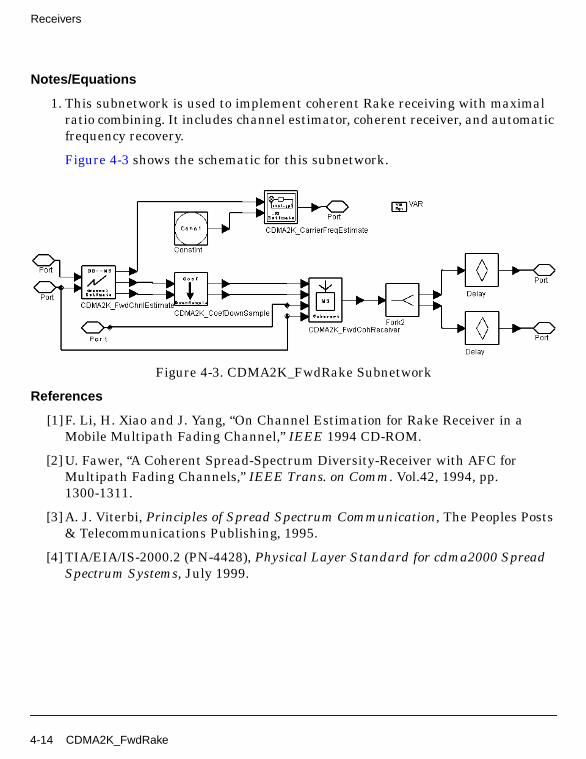
Receivers
Notes/Equations
1. This subnetwork is used to implement coherent Rake receiving with maximalratio combining. It includes channel estimator, coherent receiver, and automaticfrequency recovery.
Figure 4-3 shows the schematic for this subnetwork.
Figure 4-3. CDMA2K_FwdRake Subnetwork
References
[1]F. Li, H. Xiao and J. Yang, “On Channel Estimation for Rake Receiver in aMobile Multipath Fading Channel,” IEEE 1994 CD-ROM.
[2] U. Fawer, “A Coherent Spread-Spectrum Diversity-Receiver with AFC forMultipath Fading Channels,” IEEE Trans. on Comm. Vol.42, 1994, pp.1300-1311.
[3] A. J. Viterbi, Principles of Spread Spectrum Communication, The Peoples Posts& Telecommunications Publishing, 1995.
[4] TIA/EIA/IS-2000.2 (PN-4428), Physical Layer Standard for cdma2000 SpreadSpectrum Systems, July 1999.
4-14 CDMA2K_FwdRake

CDMA2K_FwdRake_U
Description Forward Rake receiver, spec. 3GPP2 C.S0002-A-1, Oct. 2000.Library cdma2000, Receivers
Parameters
Pin Inputs
Pin Outputs
Name Description Default Sym Type Range
SpreadRate PN chip rate, multiple of1.2288 Mcps: SR1, SR3
SR1 enum
PilotWalshLen Walsh code length for pilotchannel (longer than trafficchannel))
128 int2n , n=1,2,...,9†
TrafficWalshLen Walsh code length fortraffic channel
64 int2n , n=1,2,...,9
FrameLength frame length of outputcomplex signals
192 L int [48 *PilotWalshLen/TrafficWalshLen,
∞)
FingerNum number of fingers in Rakereceiver
3 K int [1, 5]
† In general, the Walsh code used by the pilot channel is longer than the Walsh code used by the traffic channel.
Pin Name Description Signal Type
1 SigIn received baseband signal complex
2 Pilot pilot channel PN code and Walsh code complex
3 Trffc traffic channel PN code and Walsh code complex
Pin Name Description Signal Type
4 D_PCG signal for power control component complex
CDMA2K_FwdRake_U 4-15

Receivers
Notes/Equations
1. This subnetwork implements coherent Rake receiving with maximal ratiocombining (MRC). The schematic is shown in Figure 4-4; it consists of a channelestimator, coherent receiver, and automatic frequency recovery.
Figure 4-4. Structure of CDMA2K_FwdRake
References
[1]Fu Li and Heng Xiao and Jin Yang, “On Channel Estimation for Rake Receiverin a mobile multipath fading channel,” IEEE 1994 CD-ROM
[2] Urs Fawer, “A Coherent Spread-Spectrum Diversity-Receiver with AFC forMultipath Fading Channels,” IEEE Trans. on Comm. Vol.42, pp1300-1311,1994.
[3] A. J. Viterbi, “Principles of Spread Spectrum Communication,” The PeoplesPosts & Telecommunications Publishing, 1995.
[4] 3GPP2 C.S0002_A_1, “Physical Layer Standard for cdma2000 Spread SpectrumSystems Release A-Addendum 1,” Oct. 27, 2000.
5 SigOut signal for decoder complex
6 AFC phase signal of automatic frequency control complex
Pin Name Description Signal Type
4-16 CDMA2K_FwdRake_U

CDMA2K_FwdRCreceiver
Description Foward link receiver subnetwork for different radio configurationLibrary cdma2000, Receivers
Parameters
Pin Inputs
Name Description Default Type Range
DataRate data rate in kbps 9.6 real 1.5, 2.7,4.8,9.6for ForwardRC3; andForward RC41.8,3.6,7.2,14.4for ForwardRC5
RadioConfig radio configuration forforward link: Forward RC3,Forward RC4, ForwardRC5
Forward RC3 enum
TrffcIndex traffic Walsh index 61 int [2, 15] or [17,31] or [33, 63] for ForwardRC3 and RC5, [2, 15] or [17,31] or [33, 63] or[65, 127] for ForwardRC4
FingerNum finger number of rakereceiver
1 int [1, 5]
OuterLoop outer loop power controlenable: ENABLE,DISABLE
DISABLE enum
SIR_Threshold signal-to-interference ratiorequired
0 real (-∞, ∞)
Pin Name Description Signal Type
1 In input data complex
CDMA2K_FwdRCreceiver 4-17

Receivers
Pin Outputs
Notes/Equations
1. This subnetwork provides forward link receiver for different radioconfigurations and data rates. The schematic is shown in Figure 4-5.
Figure 4-5. CDMA2K_FwdRCreceiver Subnetwork
References
[1]3GPP2 C.S0002_A_1, “Physical Layer Standard for cdma2000 Spread SpectrumSystems Release A-Addendum 1,” Oct. 27, 2000
Pin Name Description Signal Type
2 Out output data int
3 PCB power control bits int
4-18 CDMA2K_FwdRCreceiver
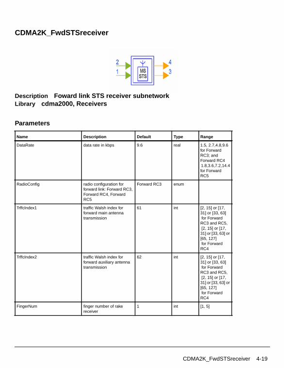
CDMA2K_FwdSTSreceiver
Description Foward link STS receiver subnetworkLibrary cdma2000, Receivers
Parameters
Name Description Default Type Range
DataRate data rate in kbps 9.6 real 1.5, 2.7,4.8,9.6for ForwardRC3; andForward RC41.8,3.6,7.2,14.4for ForwardRC5
RadioConfig radio configuration forforward link: Forward RC3,Forward RC4, ForwardRC5
Forward RC3 enum
TrffcIndex1 traffic Walsh index forforward main antennatransmission
61 int [2, 15] or [17,31] or [33, 63] for ForwardRC3 and RC5, [2, 15] or [17,31] or [33, 63] or[65, 127] for ForwardRC4
TrffcIndex2 traffic Walsh index forforward auxiliary antennatransmission
62 int [2, 15] or [17,31] or [33, 63] for ForwardRC3 and RC5, [2, 15] or [17,31] or [33, 63] or[65, 127] for ForwardRC4
FingerNum finger number of rakereceiver
1 int [1, 5]
CDMA2K_FwdSTSreceiver 4-19
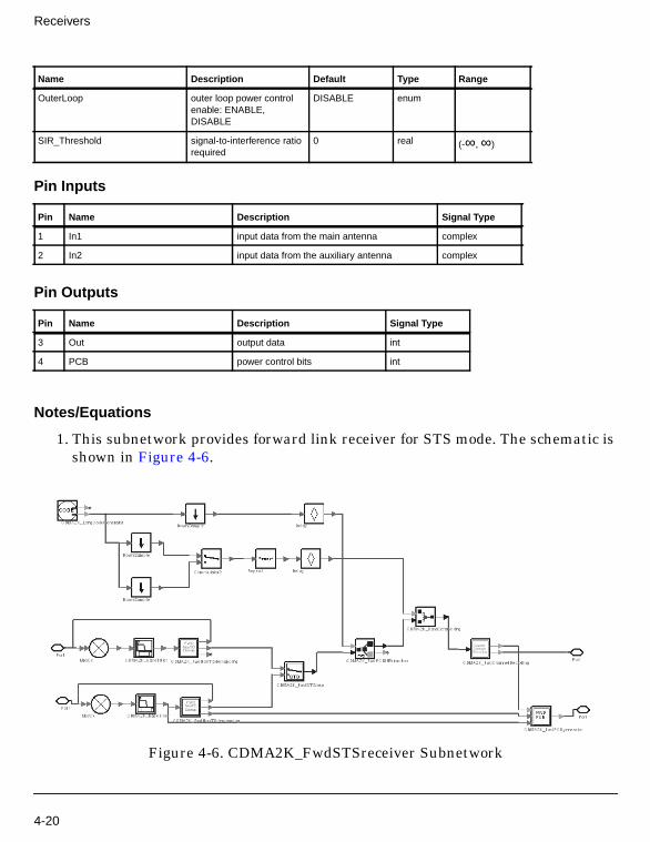
Receivers
Pin Inputs
Pin Outputs
Notes/Equations
1. This subnetwork provides forward link receiver for STS mode. The schematic isshown in Figure 4-6.
Figure 4-6. CDMA2K_FwdSTSreceiver Subnetwork
OuterLoop outer loop power controlenable: ENABLE,DISABLE
DISABLE enum
SIR_Threshold signal-to-interference ratiorequired
0 real (-∞, ∞)
Pin Name Description Signal Type
1 In1 input data from the main antenna complex
2 In2 input data from the auxiliary antenna complex
Pin Name Description Signal Type
3 Out output data int
4 PCB power control bits int
Name Description Default Type Range
4-20
References
[1]3GPP2 C.S0002_A_1, “Physical Layer Standard for cdma2000 Spread SpectrumSystems Release A-Addendum 1,” Oct. 27, 2000.
CDMA2K_FwdSTSreceiver 4-21

Receivers
CDMA2K_PhaseDetector
Description Phase DetectorLibrary cdma2000, Receivers
Pin Inputs
Pin Outputs
Notes/Equations
1. This subnetwork is used to detect the phase offset caused by Doppler shift. It isa part of the automatic frequency control loop. The signal detects the phaseoffset from the pilot signal after despreading and maximal ratio combination.
Each firing, 1 Phase token is produced when 1 SigIn token and 1 Pbit token areconsumed.
Figure 4-7 shows the schematic for this subnetwork.
Pin Name Description Signal Type
1 Pilot input signal int
2 SigIn input signal complex
Pin Name Description Signal Type
3 Phase phase offset detected by phase detector real
4-22
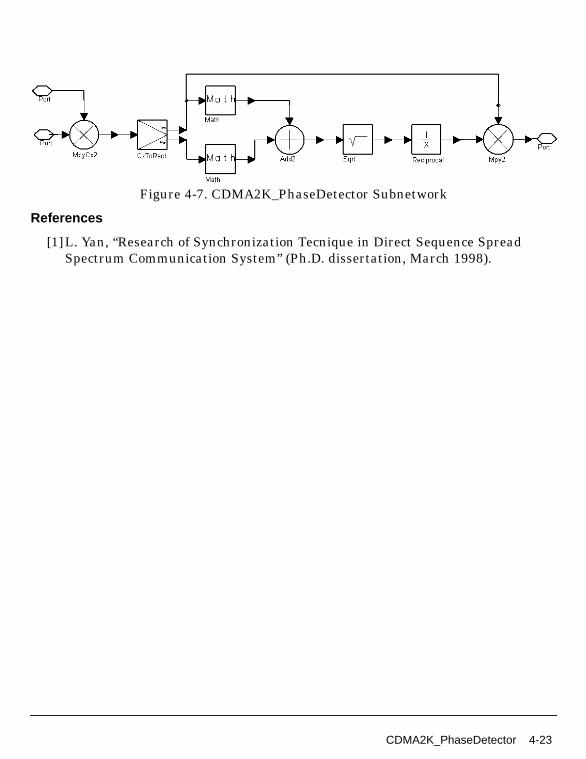
Figure 4-7. CDMA2K_PhaseDetector Subnetwork
References
[1]L. Yan, “Research of Synchronization Tecnique in Direct Sequence SpreadSpectrum Communication System” (Ph.D. dissertation, March 1998).
CDMA2K_PhaseDetector 4-23
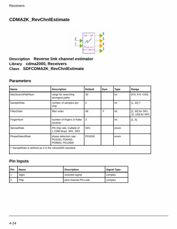
Receivers
CDMA2K_RevChnlEstimate
Description Reverse link channel estimatorLibrary cdma2000, ReceiversClass SDFCDMA2K_RevChnlEstimate
Parameters
Pin Inputs
Name Description Default Sym Type Range
MaxSearchPathNum range for searchingstrongest paths
30 int [F/4, F/4 +100]
SampleRate number of samples perchip
4 int [1, 32] †
FilterOrder filter order 48 F int [2, 50] for SR1,[2, 150] for SR3
FingerNum number of fingers in Rakereceiver
3 int [1, 5]
SpreadRate PN chip rate, multiple of1.2288 Mcps: SR1, SR3
SR1 enum
PhaseDetectRate phase detection rate:PD3200, PD6400,PD9600, PD12800
PD3200 enum
† SampleRate is defined as 4 in the cdma2000 standard.
Pin Name Description Signal Type
1 SigIn received signal complex
2 PNp pilot channel PN code complex
4-24

Pin Outputs
Notes/Equations
1. This model is used to estimate channel profile, including delay spread andstrength and phase of multipath. This information is derived from the pilotchannel signal.
Each firing, FingerNum CoeOut, FingerNum DlyOut, 1PCbit, and 1 SigOuttokens are produced when 384×SampleRate×SpreadRate/M SigIn tokens,384×SpreadRate/M PNp tokens are consumed. Here SampleRate is 4 and thedefault value of SpreadRate is SR1. M is determined by PhaseDetectRate; when
PhaseDetectRate=3.2k, M=1PhaseDetectRate=6.4k, M=2PhaseDetectRate=9.6k, M=3PhaseDetectRate=12.8k, M=4.
References
[1]TIA/EIA/IS-2000.2 (PN-4428), Physical Layer Standard for cdma2000 SpreadSpectrum Systems, July, 1999.
[2] L. Yan, “Research of Synchronization Tecnique in Direct Sequence SpreadSpectrum Communication System” (Ph.D. dissertation, March 1998).
Pin Name Description Signal Type
3 CoeOut amplitude and phase of each selected path complex
4 DlyOut delay spread of each selected path in terms ofsample
int
5 PCBit pilot and power control bits int
6 SigOut output signal after maximal ratio combination complex
CDMA2K_RevChnlEstimate 4-25
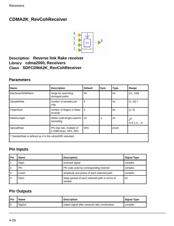
Receivers
CDMA2K_RevCohReceiver
Description Reverse link Rake receiverLibrary cdma2000, ReceiversClass SDFCDMA2K_RevCohReceiver
Parameters
Pin Inputs
Pin Outputs
Name Description Default Sym Type Range
MaxSearchPathNum range for searchingstrongest paths
30 int [11, 100]
SampleRate number of samples perchip
4 int [1, 32] †
FingerNum number of fingers in Rakereceiver
3 int [1, 5]
WalshLength Walsh code length used forspreading
16 L int2n ,n=0,1,2,...,9
SpreadRate PN chip rate, multiple of1.2288 Mcps: SR1, SR3
SR1 enum
† SampleRate is defined as 4 in the cdma2000 standard.
Pin Name Description Signal Type
1 SigIn received signal complex
2 PN PN code used by corresponding channel complex
3 CoeIn amplitude and phase of each selected path complex
4 DlyIn delay spread of each selected path in terms ofsample
int
Pin Name Description Signal Type
5 SigOut output signal after maximal ratio combination complex
4-26
Notes/Equations
1. This model is used to fulfill maximal ratio combining by collecting the energy ofthe receiving arms. The phases and attenuation factors of those paths are theinputs of this model.
Each firing, 384/WalshLength×SpreadRate SigOut tokens are produced when384×SampleRate×SpreadRate SigIn tokens, 384×SpreadRate PN tokens,FingerNum CoeIn, FingerNum DlyIn, are consumed. Here SampleRate is 4 andthe default value of SpreadRate is SR1.
References
[1]TIA/EIA/IS-2000.2 (PN-4428), Physical Layer Standard for cdma2000 SpreadSpectrum Systems, July, 1999.
CDMA2K_RevCohReceiver 4-27

Receivers
CDMA2K_RevDeHPSK
Description HPSK demodulation for reverse linkLibrary cdma2000, Receivers
Parameters
Pin Inputs
Pin Outputs
Notes/Equations
Name Description Default Type Range
PN_Offset offset of PN code 0 int [0, 511]
TransDelay used to delay long PNcode to compensate filterdelay
16 int [0, 511] †
I_PhaseCodeType type of I-phase PN code:SR1 I phase, SR3 I phase
SR1 I phase enum
Q_PhaseCodeType type of Q-phase PN code:SR1 Q phase, SR3 Qphase
SR1 Q phase enum
Q_Phase sign of sine: Sine, MinusSine
Minus Sine enum
† TransDelay is a multiple of Walsh length.
Pin Name Description Signal Type
1 D_in input data complex
2 LgCode long PN code int
Pin Name Description Signal Type
3 D_out data after demodulation complex
4-28
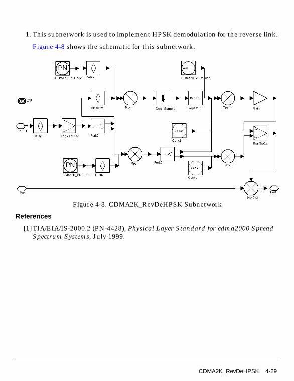
1. This subnetwork is used to implement HPSK demodulation for the reverse link.
Figure 4-8 shows the schematic for this subnetwork.
Figure 4-8. CDMA2K_RevDeHPSK Subnetwork
References
[1]TIA/EIA/IS-2000.2 (PN-4428), Physical Layer Standard for cdma2000 SpreadSpectrum Systems, July 1999.
CDMA2K_RevDeHPSK 4-29

Receivers
CDMA2K_RevRake
Description Reverse Rake ReceiverLibrary cdma2000, Receivers
Parameters
Pin Inputs
Pin Outputs
Notes/Equations
Name Description Default Sym Type Range
SpreadRate PN chip rate, multiple of1.2288 Mcps: SR1, SR3
SR1 SR enum
TrafficWalshLen Walsh code length fortraffic channel
16 int2n , n=1,2,...,9
FrameLength frame length of outputcomplex signals
384 L int [1, ∞)
FingerNum number of fingers in Rakereceiver
3 K int [1, 5]
Pin Name Description Signal Type
1 SigIn received baseband signal complex
2 Pilot pilot channel PN code and Walsh code complex
3 Trffc traffic channel PN code and Walsh code complex
Pin Name Description Signal Type
4 D_PCG signal for power control component complex
5 SigOut decision signal complex
6 PCBit power control bits int
7 AFC phase signal of automatic frequency control complex
4-30
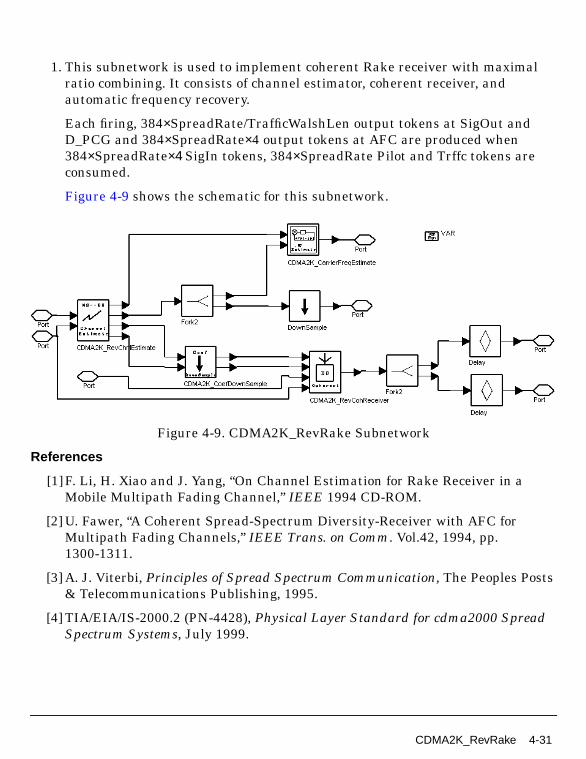
1. This subnetwork is used to implement coherent Rake receiver with maximalratio combining. It consists of channel estimator, coherent receiver, andautomatic frequency recovery.
Each firing, 384×SpreadRate/TrafficWalshLen output tokens at SigOut andD_PCG and 384×SpreadRate×4 output tokens at AFC are produced when384×SpreadRate×4 SigIn tokens, 384×SpreadRate Pilot and Trffc tokens areconsumed.
Figure 4-9 shows the schematic for this subnetwork.
Figure 4-9. CDMA2K_RevRake Subnetwork
References
[1]F. Li, H. Xiao and J. Yang, “On Channel Estimation for Rake Receiver in aMobile Multipath Fading Channel,” IEEE 1994 CD-ROM.
[2] U. Fawer, “A Coherent Spread-Spectrum Diversity-Receiver with AFC forMultipath Fading Channels,” IEEE Trans. on Comm. Vol.42, 1994, pp.1300-1311.
[3] A. J. Viterbi, Principles of Spread Spectrum Communication, The Peoples Posts& Telecommunications Publishing, 1995.
[4] TIA/EIA/IS-2000.2 (PN-4428), Physical Layer Standard for cdma2000 SpreadSpectrum Systems, July 1999.
CDMA2K_RevRake 4-31
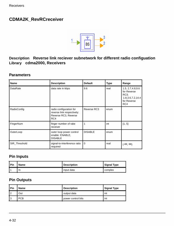
Receivers
CDMA2K_RevRCreceiver
Description Reverse link reciever subnetwork for different radio configuationLibrary cdma2000, Receivers
Parameters
Pin Inputs
Pin Outputs
Name Description Default Type Range
DataRate data rate in kbps 9.6 real 1.5, 2.7,4.8,9.6for ReverseRC3;1.8,3.6,7.2,14.4for ReverseRC4
RadioConfig radio configuration forreverse link respectively:Reverse RC3, ReverseRC4
Reverse RC3 enum
FingerNum finger number of rakereceiver
1 int [1, 5]
OuterLoop outer loop power controlenable: ENABLE,DISABLE
DISABLE enum
SIR_Threshold signal-to-interference ratiorequired
0 real (-∞, ∞)
Pin Name Description Signal Type
1 In input data complex
Pin Name Description Signal Type
2 Out output data int
3 PCB power control bits int
4-32

Notes/Equations
1. The subnetwork provides reverse link receiver for different radio configurationsand data rates. The schematic is shown in Figure 4-10.
Figure 4-10. CDMA2K_RevRCreceiver Subnetwork
References
[1]3GPP2 C.S0002_A_1, “Physical Layer Standard for cdma2000 Spread SpectrumSystems Release A-Addendum 1,” Oct. 27, 2000.
CDMA2K_RevRCreceiver 4-33

Receivers
4-34

Chapter 5: Test
5-1
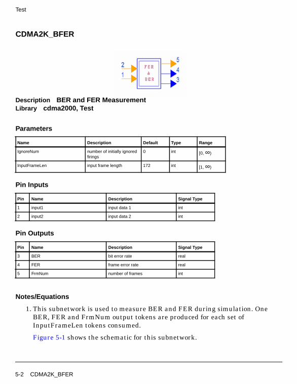
Test
CDMA2K_BFER
Description BER and FER MeasurementLibrary cdma2000, Test
Parameters
Pin Inputs
Pin Outputs
Notes/Equations
1. This subnetwork is used to measure BER and FER during simulation. OneBER, FER and FrmNum output tokens are produced for each set ofInputFrameLen tokens consumed.
Figure 5-1 shows the schematic for this subnetwork.
Name Description Default Type Range
IgnoreNum number of initially ignoredfirings
0 int [0, ∞)
InputFrameLen input frame length 172 int [1, ∞)
Pin Name Description Signal Type
1 input1 input data 1 int
2 input2 input data 2 int
Pin Name Description Signal Type
3 BER bit error rate real
4 FER frame error rate real
5 FrmNum number of frames int
5-2 CDMA2K_BFER

Figure 5-1. CDMA2K_BFER Subnetwork
2. BER and FER are measured based on the following equations.
3. The two input received signals are at one sample per bit. TheDsnCDMA2K_FwdRC3AWGN.dsn design demonstrates the use of thissubnetwork in the Examples CDMA2K/CDMA2K_BER_prj.
4. One input signal is the test signal at the receiver output bit stream thattypically includes the system delay and errors. Another input signal is thereference signal typically a delayed copy of the data bits from the transmitter.The InputFrameLen is typically set to the same value as was set in thetransmitter CDMA2K_CRC_Coder component.
The user is responsible for synchronizing the bit alignment for the signals atboth inputs. The reference signal should have a delay (typically by use of a
FER number of error framestotal frames
------------------------------------------------------------------------=
BER number of error bitstotal bits
-------------------------------------------------------------- number of error bitstotal frames InputFrameLen×-------------------------------------------------------------------------------------------= =
CDMA2K_BFER 5-3
Test
Delay component) inserted before its input pin with delay set to an integralmultiple of InputFrameLen bits. The integer multiple of InputFrameLen bits touse is dependent on the number of frames delayed in the test path.
References
[1]TIA/EIA/IS-2000.2 (PN-4428), Physical Layer Standard for cdma2000 SpreadSpectrum Systems, July 1999.
5-4 CDMA2K_BFER

CDMA2K_CDP
Description Code domain power measurementLibrary cdma2000, Test
Parameters
Pin Inputs
Notes/Equations
1. This subnetwork is used to measure code domain power. This measurement isavailable for cdma2000 SR1 systems only. The schematic for this subnetwork isshown in Figure 5-2.
Because the Walsh function length for the corresponding channel varies, it isnecessary to set the WalshLength parameter in advance. TestLength is thelength in terms of Walsh intervals for measurement. The received signal issampled at SampleRate × chip rate. The SigIn input is the received complexenvelope.
Name Description Default Sym Type Range
WalshLength Walsh code length used forspreading
128 N int2n ,n=0,1,2,...,9
TestLength number of Walsh periodsfor measurement
48 LN int [1, ∞)
SampleRate number of samples perchip
4 R int [1, ∞)
Link type of link: Forward link,Reverse link
Forward link enum
CDP_GroupNum number of output CDPgroups
1 CDP_Num int [1, ∞]
Pin Name Description Signal Type
1 SigIn received baseband signal complex
CDMA2K_CDP 5-5

Test
Each firing, N × CDP_Num tokens of CDP are collected by NumericSink whenN × (CDP_Num+1)LN × R tokens of the SigIn input are consumed.
Figure 5-2. CDMA2K_CDP Subnetwork
2. The SigIn input is at SampleRate samples per chip. The cdma2000 SR1 chiprate is 1.2288 Mcps. The MS_TxCDP_RC3.dsn design demonstrates the use ofthis subnetwork in the Examples CDMA2K/MS_TX_prj.
References
[1]3GPP2 C.S0002_A_1, “Physical Layer Standard for cdma2000 Spread SpectrumSystems Release A-Addendum 1,” Oct. 27, 2000.
[2] 3GPP2 TSG-C Interim Plenary, “Recommended Minimum PerformanceStandards for cdma2000 Spread Spectrum Mobile Stations: Release A,” Nov. 27,2000.
5-6 CDMA2K_CDP
[3] 3GPP2 TSG-C4.1, “Recommended Minimum Performance Standards forcdma2000 Spread Spectrum Base Stations: Release A,” Oct. 26, 2000.
CDMA2K_CDP 5-7

Test
CDMA2K_FwdMultiUserSrc
Description Multiuser data source for forward linkLibrary cdma2000, TestClass SDFCDMA2K_FwdMultiUserSrc
Parameters
Pin Outputs
Notes/Equations
1. This model is used to generate multiuser data for forward link.
Each firing, N tokens of D_out, N tokens of T_out, and two tokens of NRZout areproduced.
Name Description Default Sym Type Range
WalshLength length of Walsh code 64 N int2n ,n=0,1,2,...,11
UserNumber user number for forwardlink
6 M int [1, N-1]
UserIndex index of user to be tested;(= Walsh code index of theuser)
1 int [1, M]
PilotPowerRatio pilot channel power to totalpower ratio
0.20 real (0, 1)
Pin Name Description Signal Type
1 D_out traffic channel data and pilot Channel data, thepower of which is normalized
complex
2 T_out traffic channel data, the power of which is notnormalized
complex
3 NRZout data of the given traffic channel before Walshmodulation (NRZ)
real
5-8 CDMA2K_FwdMultiUserSrc

2. The data of D_out is the sum of data from the pilot and traffic channels. Thepower ratio of the pilot is set by PilotPowerRatio; the power ratio of each trafficchannel is set to the same value in the initialization. The power of D_out isnormalized.
3. The data of T_out is the sum of the traffic channels.
References
[1]TIA/EIA/IS-2000.2 (PN-4428), Physical Layer Standard for cdma2000 SpreadSpectrum Systems, July 1999.
CDMA2K_FwdMultiUserSrc 5-9

Test
CDMA2K_FwdOCNS
Description Orthogonal channel noise simulatorLibrary cdma2000, TestClass SDFCDMA2K_FwdOCNS
Parameters
Pin Outputs
Notes/Equations
1. This model is the orthogonal channel noise simulator for forward link.
Each firing, if TransmitDiversity = NON_TD, N output tokens are produced; ifTransmitDiversity = TD, 2N output tokens are produced.
2. The indexes of walsh code used as orthogonal channels can be all channels
except the channels used by pilot channel( ), paging channel( ), Sync
channel( ), TD pilot channel( ) and code channel defined by parameter
Name Description Default Sym Type Range
TransmitDiversity transmit diversity enable:NON_TD, TD
NON_TD enum
WalshLength length of Walsh code 64 N int2n , n=6,...,11
OrthogonalChNum number of the orthogonalchannel to form the noise,in TD mode, it will bedouble of number oforthogonal users
29 int
TestChIdx the Walsh index for trafficchannel(s) to be tested
61 int array
Pin Name Description Signal Type
1 output orthoganal channel noise complex
W064 W1
64
W3264 W16
128
5-10 CDMA2K_FwdOCNS
TestChIdx. Code channels , where N>64 and k is an integer such that, cannot be used. User cannot set the orthogonal index directly. The
index will be sequentially selected from the accessible index. For example, iftest channel index is 4 and 7, orthogonal channel number is 10, then theindexes used by orthogonal will be 2,3,5,6,8,9,10,11,12,13.
3. If TransmitDiversity= TD mode, each user occupies two walsh channels, so theorthogonal number must be twice of the number of users. And, the number oftest channel indexes must be even.
References
[1]3GPP2 C.S0002_A_1, “Physical Layer Standard for cdma2000 Spread SpectrumSystems Release A-Addendum 1,” Oct. 27, 2000.
[2] 3GPP2 TSG-C Interim Plenary, “Recommended Minimum PerformanceStandards for cdma2000 Spread Spectrum Mobile Stations: Release A,” Nov. 27,2000.
[3] 3GPP2 TSG-C4.1,“Recommended Minimum Performance Standards forcdma2000 Spread Spectrum Base Stations: Release A,” Oct. 26, 2000.
W64kN
0 64k≤ N<
CDMA2K_FwdOCNS 5-11

Test
CDMA2K_FwdRho
Description Rho meter for forward linkLibrary cdma2000, Test
Parameters
Pin Inputs
Notes/Equations
1. This subnetwork is used to measure waveform quality, including rho andfrequency error for a forward link. This measurement is available for cdma2000SR1 systems only. The schematic is shown in Figure 5-3.
Because the walsh function length for the corresponding channel varies, it isnecessary to set the WalshLengthMax parameter in advance. TestLength is thelength in terms of walsh intervals for measurement. The received signal issampled at SampleRate times the chip rate. The SigIn input is the receivedcomplex envelope.
Each firing, 1 token of Rho and 1 token of Dlt_F are collected by twoNumericSink components when 6 × N × LN × R tokens of SigIn are consumed.
Name Description Default Sym Type Range
WalshLengthMax maximum Walsh codelength used for spreading
128 N int2n ,n=0,1,2,...,9
TestLength number of Walsh periodsfor measurement
48 LN int [1, ∞)
SampleRate number of samples perchip
4 R int [1, ∞)
Pin Name Description Signal Type
1 SigIn received baseband signal complex
5-12 CDMA2K_FwdRho

For measurement accuracy, set TestLength large enough (according to reference[3] N × LN should be at least one power control group, in chips).
2. The SigIn input is at SampleRate samples per chip. The cdma2000 SR1 chiprate is 1.2288 Mcps. The BS_PilotSrc.dsn design demonstrates the use of thissubnetwork in the Examples CDMA2K/SignalSource_prj.
Figure 5-3. CDMA2K_FwdRho Subnetwork
References
[1]3GPP2 C.S0002_A_1, “Physical Layer Standard for cdma2000 Spread SpectrumSystems Release A-Addendum 1,” Oct. 27, 2000.
[2] 3GPP2 TSG-C Interim Plenary, “Recommended Minimum PerformanceStandards for cdma2000 Spread Spectrum Mobile Stations: Release A,” Nov. 27,2000.
[3] 3GPP2 TSG-C4.1,“Recommended Minimum Performance Standards forcdma2000 Spread Spectrum Base Stations: Release A,” Oct. 26, 2000.
CDMA2K_FwdRho 5-13
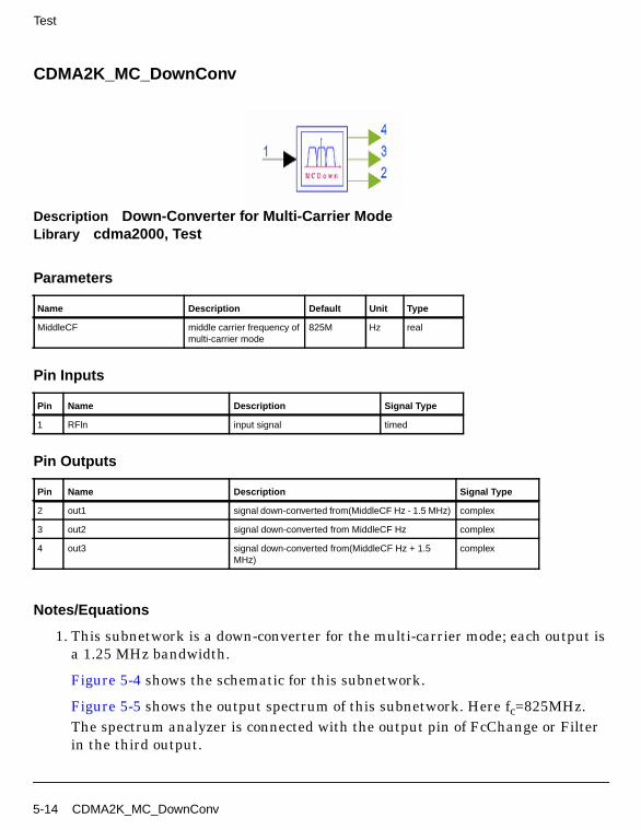
Test
CDMA2K_MC_DownConv
Description Down-Converter for Multi-Carrier ModeLibrary cdma2000, Test
Parameters
Pin Inputs
Pin Outputs
Notes/Equations
1. This subnetwork is a down-converter for the multi-carrier mode; each output isa 1.25 MHz bandwidth.
Figure 5-4 shows the schematic for this subnetwork.
Figure 5-5 shows the output spectrum of this subnetwork. Here fc=825MHz.The spectrum analyzer is connected with the output pin of FcChange or Filterin the third output.
Name Description Default Unit Type
MiddleCF middle carrier frequency ofmulti-carrier mode
825M Hz real
Pin Name Description Signal Type
1 RFln input signal timed
Pin Name Description Signal Type
2 out1 signal down-converted from(MiddleCF Hz - 1.5 MHz) complex
3 out2 signal down-converted from MiddleCF Hz complex
4 out3 signal down-converted from(MiddleCF Hz + 1.5MHz)
complex
5-14 CDMA2K_MC_DownConv
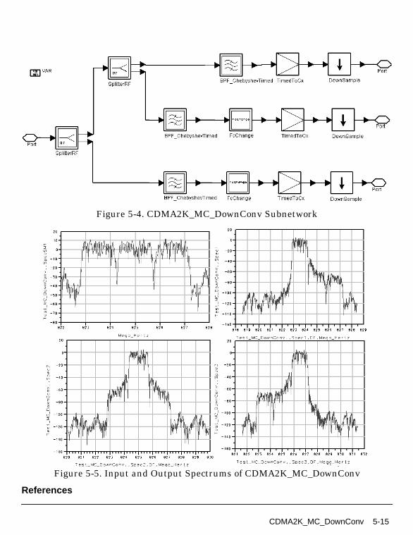
Figure 5-4. CDMA2K_MC_DownConv Subnetwork
Figure 5-5. Input and Output Spectrums of CDMA2K_MC_DownConv
References
CDMA2K_MC_DownConv 5-15

Test
[1]TIA/EIA/IS-2000.2 (PN-4428), Physical Layer Standard for cdma2000 SpreadSpectrum Systems, July 1999.
5-16 CDMA2K_MC_DownConv
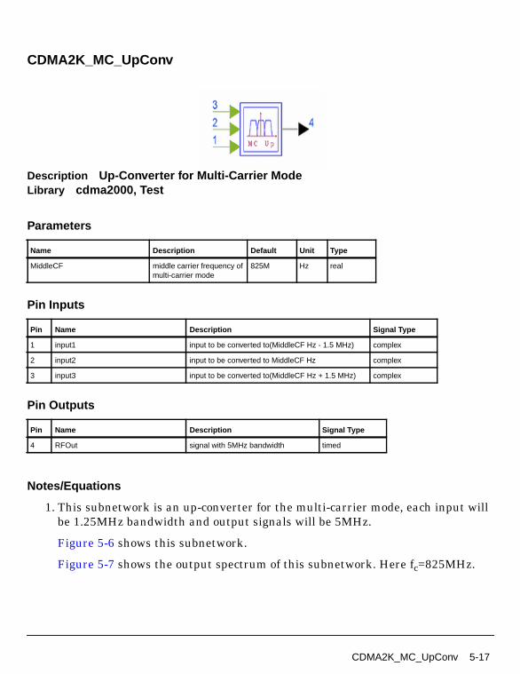
CDMA2K_MC_UpConv
Description Up-Converter for Multi-Carrier ModeLibrary cdma2000, Test
Parameters
Pin Inputs
Pin Outputs
Notes/Equations
1. This subnetwork is an up-converter for the multi-carrier mode, each input willbe 1.25MHz bandwidth and output signals will be 5MHz.
Figure 5-6 shows this subnetwork.
Figure 5-7 shows the output spectrum of this subnetwork. Here fc=825MHz.
Name Description Default Unit Type
MiddleCF middle carrier frequency ofmulti-carrier mode
825M Hz real
Pin Name Description Signal Type
1 input1 input to be converted to(MiddleCF Hz - 1.5 MHz) complex
2 input2 input to be converted to MiddleCF Hz complex
3 input3 input to be converted to(MiddleCF Hz + 1.5 MHz) complex
Pin Name Description Signal Type
4 RFOut signal with 5MHz bandwidth timed
CDMA2K_MC_UpConv 5-17

Test
Figure 5-6. CDMA2K_MC_UpConv Subnetwork
Figure 5-7. Output Spectrum of CDMA2K_MC_UpConv
References
[1]TIA/EIA/IS-2000.2 (PN-4428), Physical Layer Standard for cdma2000 SpreadSpectrum Systems, July 1999.
5-18 CDMA2K_MC_UpConv
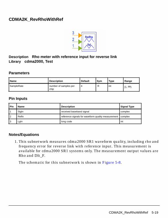
CDMA2K_RevRhoWithRef
Description Rho meter with reference input for reverse linkLibrary cdma2000, Test
Parameters
Pin Inputs
Notes/Equations
1. This subnetwork measures cdma2000 SR1 waveform quality, including rho andfrequency error for reverse link with reference input. This measurement isavailable for cdma2000 SR1 systems only. The measurement output values areRho and Dlt_F.
The schematic for this subnetwork is shown in Figure 5-8.
Name Description Default Sym Type Range
SampleRate number of samples perchip
4 R int [1, ∞)
Pin Name Description Signal Type
1 SigIn received baseband signal complex
2 RefIn reference signals for waveform quality measurement complex
3 LgIn long code int
CDMA2K_RevRhoWithRef 5-19

Test
Figure 5-8. CDMA2K_RevRhoWithRef Subnetwork
The MS_TxRhoRC3.dsn design (in the Examples > CDMA2K >MS_TX_prjdirectory) demonstrates the use of this subnetwork .
The received signal is sampled at SampleRate times the chip rate. Thecdma2000 SR1 chip rate is 1.2288 Mcps. The SigIn input denotes the receivedsignal complex envelope; RefIn is the reference complex signal; LgIn is the longcode input and should be set to the same long code as used in the generation ofthe RefIn signal.
For measurement recording, 1 value of Rho and 1 value of Dlt_F (frequencyerror) are collected by NumericSink components. For this one value, thenumber of SigIn and RefIn tokens consumed is 6*96*32*R, and the number ofLgIn tokens consumed is 6*96*32. Per the cdma2000 specification, the Rhomeasurement is performed on a signal segment with duration greater than orequal to 500 µSec. For the purpose of the Agilent CDMA2000 Design Library,Rho measurements are made for 96*32 chips (96*32*R samples) whichrepresents a 2.5 msec duration. The CDMA2K_RevRhoWithRefCal collectssignals for 6 of these time durations and outputs the Rho and Dlt_F values foronly the 6th time duration interval.
5-20 CDMA2K_RevRhoWithRef
2. The SampleRate default value is 4, which is compliant with the cdma2000specification. The compensatory filters (shown as FIR filters) in thissubnetwork are designed based on this default value. The following discussionis based on SampleRate = 4.
3. This subnetwork includes auto-synchronization for the SigIn and RefIn signals.Typically the SigIn signal has a delay relative to the RefIn signal andsynchronization is required. Auto-synchronization is achieved when the SigIndelay is from 0 to 49.4 µsec, i.e., 243 samples or 60.75 chips (chip rate = 1.2288Mcps, SampleRate = 4).
It is common in communication systems for a delay to be introduced in thesignal path.
If the signal delay (SigIn pin 1) is less than 49.4 µSec (relative to the reference -RefIn pin 2), this subnetwork will work correctly without any specialadjustment.
This subnetwork will not work with negative delay (SigIn relative to RefIn). Ifthe input to RefIn lags behind the input to SigIn, improper Rho and Dlt_Fvalues will result.
If the delay of SigIn relative to RefIn is greater than 49.4 µSec (i.e., 243 samplesor 60.75 chips), the synchronization between SigIn and RefIn must be achievedwith additional external components. For this case, the user must insertappropriate delay components into the RefIn, SigIn and LgIn paths. For thiscase, the user must know the existing delay in the signal path and call this Tsec. The user must perform separate calibration simulations to determine thisvalue T (that calibration is not discussed here); the following discussionassumes the user knows the T sec value.
From Figure 5-8, Rho and Dlt_F measurements are made usingCDMA2K_RevRhoWithRefCal. The Rho and Dlt_F are measured for each 2.5mSec duration (96*32*R samples). Therefore, the delay to be inserted in theRefIn path should be BL*96*32*R samples (BL*2.5 mSec) and LgIn pathshould be BL*96*32 chips. BL is an integer ≥ 0. Let the delay to be inserted inthe SigIn path be M sec. The total SigIn path delay inclusive of the originalSigIn path delay of T will be (M sec + T sec). The user will select M to result in arelative delay, δ, of SigIn to RefIn inputs to CDMA2K_RevRhoWithRef that iswithin the autosynchronization delay range 0 ≤ δ ≤ 49.4 µsec. M is thus selectedsuch that 0 ≤ (M sec + T sec) - (BL*2.5 mSec) ≤ 49.4 µsec.
CDMA2K_RevRhoWithRef 5-21
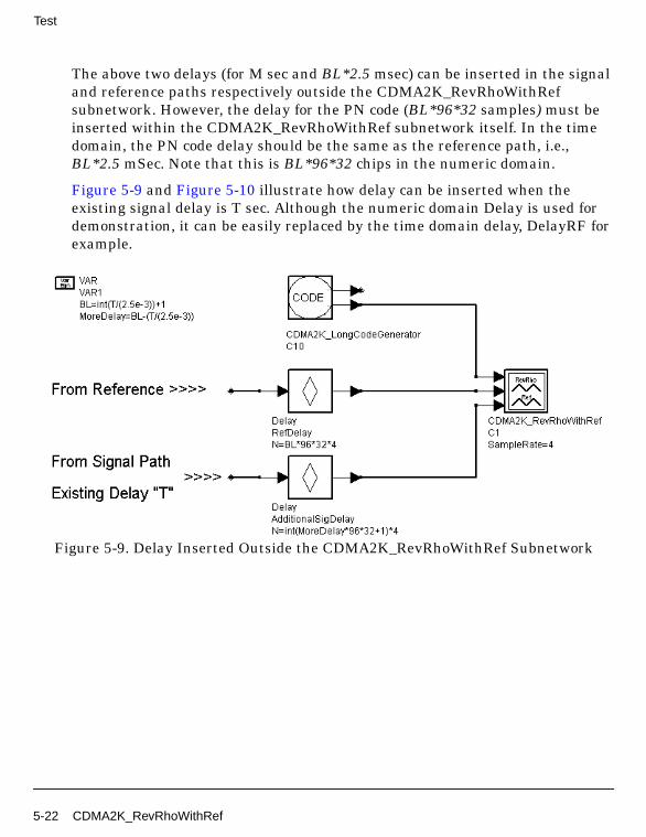
Test
The above two delays (for M sec and BL*2.5 msec) can be inserted in the signaland reference paths respectively outside the CDMA2K_RevRhoWithRefsubnetwork. However, the delay for the PN code (BL*96*32 samples) must beinserted within the CDMA2K_RevRhoWithRef subnetwork itself. In the timedomain, the PN code delay should be the same as the reference path, i.e.,BL*2.5 mSec. Note that this is BL*96*32 chips in the numeric domain.
Figure 5-9 and Figure 5-10 illustrate how delay can be inserted when theexisting signal delay is T sec. Although the numeric domain Delay is used fordemonstration, it can be easily replaced by the time domain delay, DelayRF forexample.
Figure 5-9. Delay Inserted Outside the CDMA2K_RevRhoWithRef Subnetwork
5-22 CDMA2K_RevRhoWithRef

Figure 5-10. Delay Inserted Inside the CDMA2K_RevRhoWithRef Subnetwork
References
[1]3GPP2 C.S0002_A_1, “Physical Layer Standard for cdma2000 Spread SpectrumSystems Release A-Addendum 1,” Oct. 27, 2000.
[2] 3GPP2 TSG-C Interim Plenary, “Recommended Minimum PerformanceStandards for cdma2000 Spread Spectrum Mobile Stations: Release A,” Nov. 27,2000.
[3] 3GPP2 TSG-C4.1,“Recommended Minimum Performance Standards forcdma2000 Spread Spectrum Base Stations: Release A,” Oct. 26, 2000.
CDMA2K_RevRhoWithRef 5-23

Test
5-24

Chapter 6: Transmission
6-1

Transmission
CDMA2K_BSTX
Description Base station transmitterLibrary cdma2000, TransmissionClass SDFCDMA2K_BSTX
Parameters
Pin Inputs
Pin Outputs
Notes/Equations
1. This model is used to allocate real base station power for data transmission.
Each firing, 1 D_out token is produced when 1 D_in token is consumed.
References
[1]TIA/EIA/IS-2000.2 (PN-4428), Physical Layer Standard for cdma2000 SpreadSpectrum Systems, July 1999.
Name Description Default Unit Type Range
BS_Power base station transmissionpower
10.0 W real (0, ∞)
Pin Name Description Signal Type
1 D_in input data complex
Pin Name Description Signal Type
2 D_out output data complex
6-2 CDMA2K_BSTX
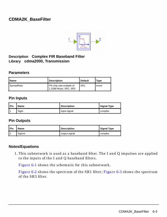
CDMA2K_BaseFilter
Description Complex FIR Baseband FilterLibrary cdma2000, Transmission
Parameters
Pin Inputs
Pin Outputs
Notes/Equations
1. This subnetwork is used as a baseband filter. The I and Q impulses are appliedto the inputs of the I and Q baseband filters.
Figure 6-1 shows the schematic for this subnetwork.
Figure 6-2 shows the spectrum of the SR1 filter; Figure 6-3 shows the spectrumof the SR3 filter.
Name Description Default Type
SpreadRate PN chip rate,multiple of1.2288 Mcps: SR1, SR3
SR1 enum
Pin Name Description Signal Type
1 SigIn input signal complex
Pin Name Description Signal Type
2 SigOut output signal complex
CDMA2K_BaseFilter 6-3

Transmission
Figure 6-1. CDMA2K_BaseFilter Subnetwork
Figure 6-2. SR1 Filter Spectrum
6-4 CDMA2K_BaseFilter

Figure 6-3. SR3 Filter Spectrum
References
[1]TIA/EIA/IS-2000.2 (PN-4428), Physical Layer Standard for cdma2000 SpreadSpectrum Systems, July 1999.
CDMA2K_BaseFilter 6-5
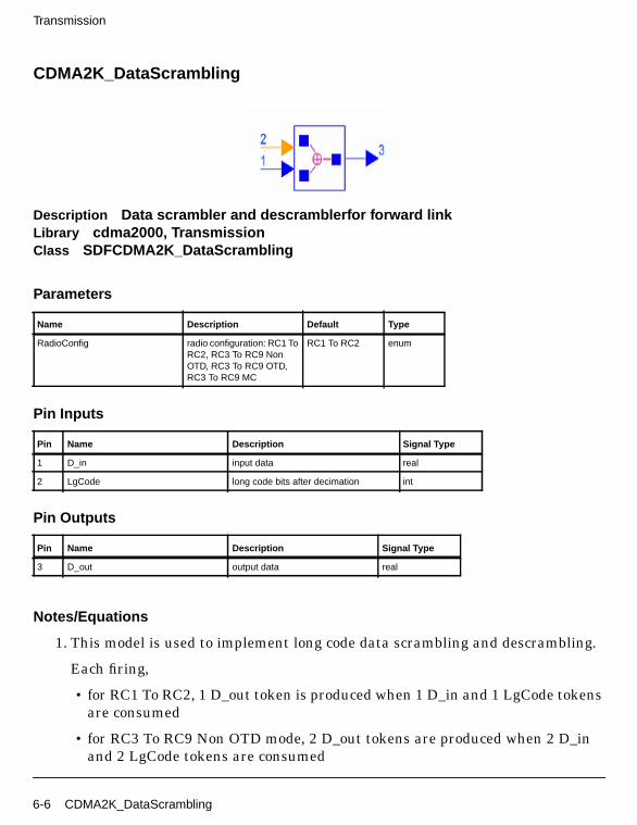
Transmission
CDMA2K_DataScrambling
Description Data scrambler and descramblerfor forward linkLibrary cdma2000, TransmissionClass SDFCDMA2K_DataScrambling
Parameters
Pin Inputs
Pin Outputs
Notes/Equations
1. This model is used to implement long code data scrambling and descrambling.
Each firing,
• for RC1 To RC2, 1 D_out token is produced when 1 D_in and 1 LgCode tokensare consumed
• for RC3 To RC9 Non OTD mode, 2 D_out tokens are produced when 2 D_inand 2 LgCode tokens are consumed
Name Description Default Type
RadioConfig radio configuration: RC1 ToRC2, RC3 To RC9 NonOTD, RC3 To RC9 OTD,RC3 To RC9 MC
RC1 To RC2 enum
Pin Name Description Signal Type
1 D_in input data real
2 LgCode long code bits after decimation int
Pin Name Description Signal Type
3 D_out output data real
6-6 CDMA2K_DataScrambling

• for RC3 To RC9 OTD, 4 D_out tokens are produced when 4 D_in and 4LgCode tokens are consumed
• for RC3 To RC9 MC mode, 6 D_out tokens are produced when 6 D_in and 6LgCode tokens are consumed.
References
[1]TIA/EIA/IS-2000.2 (PN-4428), Physical Layer Standard for cdma2000 SpreadSpectrum Systems, July 1999.
CDMA2K_DataScrambling 6-7

Transmission
CDMA2K_DataScrambling_U
Description Data scrambler and descrambler for forward link, spec. 3GPP2C.S0002-A-1, Oct. 2000.Library cdma2000, TransmissionClass SDFCDMA2K_DataScrambling_U
Parameters
Pin Inputs
Pin Outputs
Notes/Equations
1. This model is used to implement long code data scrambling and descrambling.
Each firing,
• for RC1 To RC2, 1 D_out tokens are produced when 1 D_in and 1 LgCodetokens are consumed
Name Description Default Type
RadioConfig radio configuration: RC1 ToRC2, RC3 To RC5 Non TD,RC3 To RC5 TD, RC6 ToRC9 MC
RC1 To RC2 enum
Pin Name Description Signal Type
1 D_in input data real
2 LgCode long code bits after decimation int
Pin Name Description Signal Type
3 D_out output data real
6-8 CDMA2K_DataScrambling_U
• for RC3 To RC5 Non TD, 2 D_out tokens are produced when 2 D_in and 2LgCode tokens are consumed
• for RC3 To RC5 TD, 4 D_out tokens are produced when 4 D_in and 4 LgCodetokens are consumed
• for RC6 To RC9 MC, 6 D_out tokens are produced when 6 D_in and 6 LgCodetokens are consumed
2. Data scrambling is accomplished as follows.
• for RC1 To RC2, data scrambling is performed by the modulo-2 addition ofthe modulation symbol with the binary value of the long code PN chips. ThisPN sequence is the equivalent of the long code operating at 1.2288×N MHZ,where N is the chip rate / 1.2288 Mcps. Only the first output of every M chipsis used, M is the decimation rate equal to the chip rate divided by themodulation symbol rate.
• for RC3 To RC5, data scrambling is performed in groups of 2M modulationsymbols, where M is 1 for Non TD modes and 2 for TD mode. Modulo-2addition is performed on the modulation symbols with the binary value of thelong code PN chips that is valid at the start of the 2M modulation symbol forthe first M modulation symbols of each group, and is valid just prior to thestart of the 2M modulation symbol for the second M modulation symbols.
• for RC6 To RC9, data scrambling is performed in groups of 2M modulationsymbols, where M is 3 for MC mode. Modulo-2 addition is performed on themodulation symbols with the binary value of the long code PN chips that isvalid at the start of the 2M modulation symbol for the first M modulationsymbols of each group, and is valid just prior to the start of the 2Mmodulation symbol for the second M modulation symbols.
References
[1]3GPP2 C.S0002_A_1, “Physical Layer Standard for cdma2000 Spread SpectrumSystems Release A-Addendum 1,” Oct. 27, 2000.
CDMA2K_DataScrambling_U 6-9

Transmission
CDMA2K_FIR
Description FIR baseband filterLibrary cdma2000, TransmissionClass SDFCDMA2K_FIR
Parameters
Pin Inputs
Pin Outputs
Notes/Equations
1. This model is used as a 48-order FIR filter for SR1, or as a 108-order FIR filterfor SR3.
2. The baseband filters have a frequency response S(f) that satisfies the limitsgiven in Figure 6-4. Specifically, the normalized frequency response of the filtermust be contained within in the passband , and must be ≤ - in thestopband .
• for SR1 the numerical values for the parameters are = 1.5 dB, = 40 dB,fp = 590 kHz, and fs = 740 kHz.
Name Description Default Type
SpreadRate PN chip rate; multiple of1.2288 Mcps: SR1, SR3
SR1 enum
Pin Name Description Signal Type
1 D_in input data real
Pin Name Description Signal Type
2 D_out output data real
δ1 0 f f p≤ ≤ δ2
f f s≥
δ1 δ2
6-10 CDMA2K_FIR
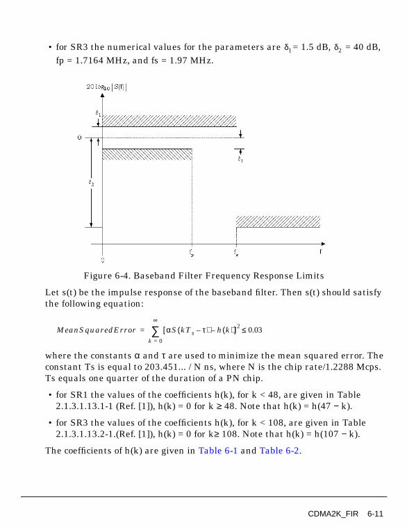
• for SR3 the numerical values for the parameters are = 1.5 dB, = 40 dB,fp = 1.7164 MHz, and fs = 1.97 MHz.
Figure 6-4. Baseband Filter Frequency Response Limits
Let s(t) be the impulse response of the baseband filter. Then s(t) should satisfythe following equation:
where the constants α and τ are used to minimize the mean squared error. Theconstant Ts is equal to 203.451... / N ns, where N is the chip rate/1.2288 Mcps.Ts equals one quarter of the duration of a PN chip.
• for SR1 the values of the coefficients h(k), for k < 48, are given in Table2.1.3.1.13.1-1 (Ref. [1]), h(k) = 0 for k ≥ 48. Note that h(k) = h(47 − k).
• for SR3 the values of the coefficients h(k), for k < 108, are given in Table2.1.3.1.13.2-1.(Ref. [1]), h(k) = 0 for k≥ 108. Note that h(k) = h(107 − k).
The coefficients of h(k) are given in Table 6-1 and Table 6-2.
δ1 δ2
MeanSquaredError αS kTs τ–( ) h k( )–[ ]20.03≤
k 0=
∞
∑=
CDMA2K_FIR 6-11

Transmission
Table 6-1. Coefficients of h(k) for Spreading Rate 1
k h[k] k h[k]
0,47 -0.025288315 12,37 0.007874526
1,46 -0.034167931 13,34 0.084368728
2,45 -0.035752323 14,33 0.126869306
3,44 -0.016733702 15,34 0.094528345
4,43 0.021602514 16,31 -0.012839661
5,42 0.064938487 17,30 -0.143477028
6,41 0.091002137 18,29 -0.211829088
7,40 0.081894974 19,28 -0.140513128
8,39 0.037071157 20,27 0.094601918
9,38 -0.021998074 21,26 0.441387140
10,37 -0.060716277 22,25 0.785875640
11,36 -0.051178658 23,24 1.0
Table 6-2. Coefficients of h(k) for Spreading Rate 3
k h(k) k h(k)
0, 107 0.005907324 27, 80 0.036864993
1, 106 0.021114345 28, 79 0.032225981
2, 105 0.017930022 29, 78 0.007370446
3, 104 0.019703955 30, 77 -0.025081919
4, 103 0.011747086 31, 76 -0.046339352
5, 102 0.001239201 32, 75 -0.042011421
6, 101 -0.00892579 33, 74 -0.011379513
7, 100 -0.01333914 34, 73 0.030401507
8, 99 -0.00986819 35, 72 0.059332552
9, 98 -0.00019046 36, 71 0.055879297
10, 97 0.01034771 37, 70 0.017393708
11, 96 0.015531711 38, 69 -0.037885556
12, 95 0.011756251 39, 68 -0.078639005
13, 94 0.000409244 40, 67 -0.077310571
14, 93 -0.01243954 41, 66 -0.027229017
15, 92 -0.01916985 42, 65 0.049780118
16, 91 -0.01500653 43, 64 0.111330557
17, 90 -0.00124565 44, 63 0.115580285
6-12 CDMA2K_FIR

References
[1]TIA/EIA/IS-2000.2 (PN-4428), Physical Layer Standard for cdma2000 SpreadSpectrum Systems, July 1999.
18, 89 0.014862732 45, 62 0.046037444
19, 88 0.023810108 46, 61 -0.073329573
20, 87 0.019342903 47, 60 -0.182125302
21, 86 0.002612151 48, 59 -0.20734917
22, 85 -0.01766272 49, 58 -0.097600349
23, 84 -0.02958801 50, 57 0.148424686
24, 83 -0.02493396 51, 56 0.473501031
25, 82 -0.00457532 52, 55 0.779445702
26, 81 0.020992966 53, 54 0.964512513
Table 6-2. Coefficients of h(k) for Spreading Rate 3 (continued)
k h(k) k h(k)
CDMA2K_FIR 6-13

Transmission
CDMA2K_FwdPCBitExtraction
Description Power control bit extractor for forward linkLibrary cdma2000, TransmissionClass SDFCDMA2K_FwdPCBitExtraction
Parameters
Pin Inputs
Pin Outputs
Notes/Equations
1. This model is used to extract power control bits from decoded traffic bits andreplace PCBit with 0. This model processes one power control group as a block.
Name Description Default Type
RadioConfig radio configuration: RC1,RC2, RC3 Non OTD, RC3OTD, RC4, RC5 Non OTD,RC5 OTD, RC6 DS NonOTD, RC6 DS OTD, RC6MC, RC7 DS, RC7 MC,RC8 DS Non OTD, RC8DS OTD, RC8 MC, RC9DS, RC9 MC
RC1 enum
Pin Name Description Signal Type
1 D_in input data real
2 LgCode long code bits after decimation int
Pin Name Description Signal Type
3 PCBit power control bit int
4 D_out data after extracting power control bit andde-scrambling
real
6-14 CDMA2K_FwdPCBitExtraction
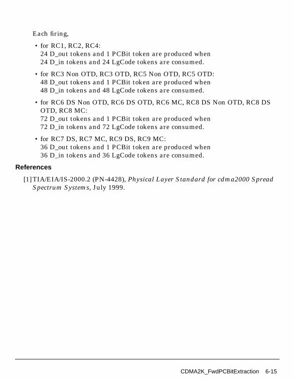
Each firing,
• for RC1, RC2, RC4:24 D_out tokens and 1 PCBit token are produced when24 D_in tokens and 24 LgCode tokens are consumed.
• for RC3 Non OTD, RC3 OTD, RC5 Non OTD, RC5 OTD:48 D_out tokens and 1 PCBit token are produced when48 D_in tokens and 48 LgCode tokens are consumed.
• for RC6 DS Non OTD, RC6 DS OTD, RC6 MC, RC8 DS Non OTD, RC8 DSOTD, RC8 MC:72 D_out tokens and 1 PCBit token are produced when72 D_in tokens and 72 LgCode tokens are consumed.
• for RC7 DS, RC7 MC, RC9 DS, RC9 MC:36 D_out tokens and 1 PCBit token are produced when36 D_in tokens and 36 LgCode tokens are consumed.
References
[1]TIA/EIA/IS-2000.2 (PN-4428), Physical Layer Standard for cdma2000 SpreadSpectrum Systems, July 1999.
CDMA2K_FwdPCBitExtraction 6-15

Transmission
CDMA2K_FwdPCBitExtraction_U
Description Power control bit extractor for forward link, spec. 3GPP2 C.S0002-A-1,Oct. 2000.Library cdma2000, TransmissionClass SDFCDMA2K_FwdPCBitExtraction_U
Parameters
Pin Inputs
Pin Outputs
Notes/Equations
1. This model is used to extract power control bit from decoded traffic bits andreplace power control bit with 0. This model processes one power control groupas a block.
Name Description Default Type
RadioConfig radio configuration: RC1,RC2, RC3 Non TD, RC3TD, RC4, RC5 Non TD,RC5 TD, RC6, RC7, RC8,RC9
RC1 enum
Pin Name Description Signal Type
1 D_in input data real
2 LgCode long code bits after decimation int
Pin Name Description Signal Type
3 PCBit power control bit int
4 D_out data after extracting power control bit andde-scrambling
real
6-16 CDMA2K_FwdPCBitExtraction_U

Each firing,
• for RC1, RC2, RC4, 24 D_out tokens and 1 PCBit token are produced when24 D_in tokens and 24 LgCode tokens are consumed.
• for RC3 Non TD, RC3 TD, RC5 Non TD, RC5 TD, 48 D_out tokens and 1PCBit token are produced when 48 D_in tokens and 48 LgCode tokens areconsumed.
• for RC6 and RC8: 72 D_out tokens and 1 PCBit token are produced when 72D_in tokens and 72 LgCode tokens are consumed.
• for RC7 and RC9: 36 D_out tokens and 1 PCBit token are produced when 36D_in tokens and 36 LgCode tokens are consumed.
The model extracts the power control bit at every power control group andsends it to the mobile station power controller, then replaces the power controlbits with 0.
As shown in Table 6-3, 1, 2, 3, 4 or 6 analogy values will be combined into oneinteger type power control bit at the position indicated by the long code of lastpower control group. The power control bit starting position can be derived fromthe long code value.
References
Table 6-3. Power Control Bit Duration and Power Level
Radio configurationPuncturedModulation Symbols
Starting SymbolPositions
Scrambling Bits (MSB ->LSB)
1 2 0, 1, ... , 15 23, 22, 21, 20
2 1 0, 1, ... , 15 23, 22, 21, 20
3 (non-TD) 4 0, 2, ... , 30 47, 46, 45, 44
3 (TD) 4 0, 4, ... , 28 47, 46, 45
4 2 0, 2, ... , 14 23, 22, 21
5 (non-TD) 4 0, 2, ... , 30 47, 46, 45, 44
5 (TD) 4 0, 4, ... , 28 47, 46, 45
6 6 0, 6, ... , 42 71, 70, 69
7 3 0, 3, ... , 21 35, 34, 33
8 6 0, 6, ... , 42 71, 70, 69
9 3 0, 3, ... , 21 35, 34, 33
CDMA2K_FwdPCBitExtraction_U 6-17
Transmission
[1]3GPP2 C.S0002_A_1, “Physical Layer Standard for cdma2000 Spread SpectrumSystems Release A-Addendum 1,” Oct. 27, 2000.
6-18 CDMA2K_FwdPCBitExtraction_U
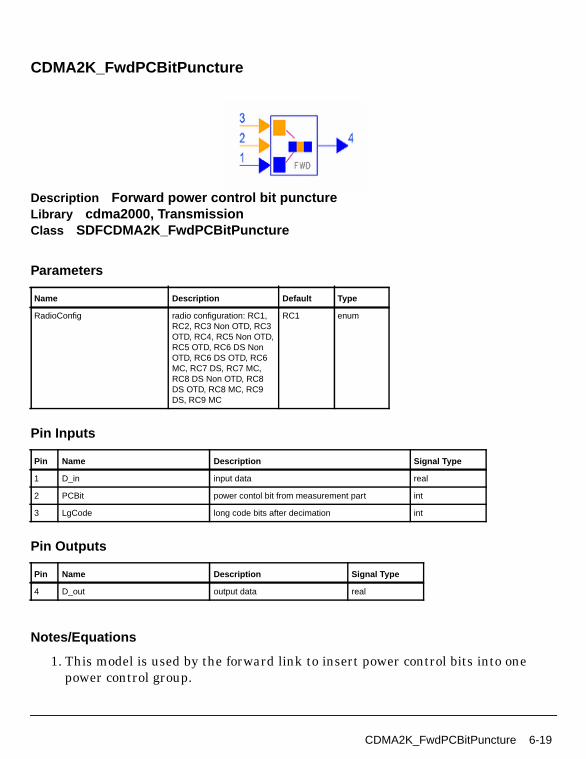
CDMA2K_FwdPCBitPuncture
Description Forward power control bit punctureLibrary cdma2000, TransmissionClass SDFCDMA2K_FwdPCBitPuncture
Parameters
Pin Inputs
Pin Outputs
Notes/Equations
1. This model is used by the forward link to insert power control bits into onepower control group.
Name Description Default Type
RadioConfig radio configuration: RC1,RC2, RC3 Non OTD, RC3OTD, RC4, RC5 Non OTD,RC5 OTD, RC6 DS NonOTD, RC6 DS OTD, RC6MC, RC7 DS, RC7 MC,RC8 DS Non OTD, RC8DS OTD, RC8 MC, RC9DS, RC9 MC
RC1 enum
Pin Name Description Signal Type
1 D_in input data real
2 PCBit power contol bit from measurement part int
3 LgCode long code bits after decimation int
Pin Name Description Signal Type
4 D_out output data real
CDMA2K_FwdPCBitPuncture 6-19

Transmission
Each firing,
• for RC1, RC2, RC4:24 D_out tokens are produced when24 D_in tokens, 24 LgCode and 1 PCBit tokens are consumed.
• for RC3 Non OTD, RC3 OTD, RC5 Non OTD, RC5 OTD:48 D_out tokens are produced when48 D_in, 48 LgCode, and 1 PCBit tokens are consumed.
• for RC6 DS Non OTD, RC6 DS OTD, RC6 MC, RC8 DS Non OTD, RC8 DSOTD, RC8 MC:72 D_out tokens are producedwhen 72 D_in, 72 LgCode, and 1 PCBit tokens are consumed.
• for RC7 DS, RC7 MC, RC9 DS, RC9 MC:36 D_out tokens are produced when36 D_in tokens, 36 LgCode and 1 PCBit tokens are consumed.
References
[1]TIA/EIA/IS-2000.2 (PN-4428), Physical Layer Standard for cdma2000 SpreadSpectrum Systems, July 1999.
6-20 CDMA2K_FwdPCBitPuncture
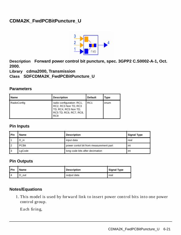
CDMA2K_FwdPCBitPuncture_U
Description Forward power control bit puncture, spec. 3GPP2 C.S0002-A-1, Oct.2000.Library cdma2000, TransmissionClass SDFCDMA2K_FwdPCBitPuncture_U
Parameters
Pin Inputs
Pin Outputs
Notes/Equations
1. This model is used by forward link to insert power control bits into one powercontrol group.
Each firing,
Name Description Default Type
RadioConfig radio configuration: RC1,RC2, RC3 Non TD, RC3TD, RC4, RC5 Non TD,RC5 TD, RC6, RC7, RC8,RC9
RC1 enum
Pin Name Description Signal Type
1 D_in input data real
2 PCBit power contol bit from measurement part int
3 LgCode long code bits after decimation int
Pin Name Description Signal Type
4 D_out output data real
CDMA2K_FwdPCBitPuncture_U 6-21

Transmission
• for RC1, RC2, RC4, 24 D_out tokens are produced when 24 D_in tokens, 24LgCode tokens, and 1 PCBit token are consumed.
• for RC3 Non OTD, RC3 OTD, RC5 Non OTD, RC5 OTD, 48 D_out tokens areproduced when 48 D_in tokens, 48 LgCode tokens, and 1 PCBit token areconsumed.
• for RC6, RC8: 72 D_out tokens are produced when 72 D_in tokens, 72 LgCodetokens, and 1 PCBit token are consumed.
• for RC7, RC9: 36 D_out tokens are produced when 36 D_in tokens, 36 LgCodetokens, and 1 PCBit token are consumed.
As shown in Table 6-4, 1, 2, 3, 4 or 6 information bits are replaced with powercontrol bit (with the same value) at the position indicated by the long code oflast power control group. The power control bit initial (first bit) position can bederived from the long code value.
An n-bit (n=3 or 4) binary number with values 0 through 2n -1 formed by thescrambling bits as shown in Table 6-4 will be used to determine the powercontrol bit starting position by indexing the list in Table 6-4.
References
[1]3GPP2 C.S0002_A_1, “Physical Layer Standard for cdma2000 Spread SpectrumSystems Release A-Addendum 1,” Oct. 27, 2000.
Table 6-4. Power Control Bit Duration and Power Level
Radio configurationPuncturedModulation Symbols
Starting SymbolPositions
Scrambling Bits (MSB ->LSB)
1 2 0, 1,..., 15 23, 22, 21, 20
2 1 0, 1,..., 15 23, 22, 21, 20
3 (non-TD) 4 0, 2,..., 30 47, 46, 45, 44
3 (TD) 4 0, 4,..., 28 47, 46, 45
4 2 0, 2,..., 14 23, 22, 21
5 (non-TD) 4 0, 2,..., 30 47, 46, 45, 44
5 (TD) 4 0, 4,..., 28 47, 46, 45
6 6 0, 6,..., 42 71, 70, 69
7 3 0, 3,..., 21 35, 34, 33
8 6 0, 6,..., 42 71, 70, 69
9 3 0, 3,..., 21 35, 34, 33
6-22 CDMA2K_FwdPCBitPuncture_U

CDMA2K_FwdPCBitPuncture_U 6-23

Transmission
CDMA2K_FwdPowerAllocation
Description Power allocator for base station channelsLibrary cdma2000, TransmissionClass SDFCDMA2K_FwdPowerAllocation
Parameters
Name Description Default Sym Type Range
PilotPowerRatio pilot channel power to totalpower ratio
0.2 real (0, 1) †
SyncPowerRatio sync channel power to totalpower ratio
0.025 real [0, 1)
PagingPowerRatio paging channel power tototal power ratio
0.063 real [0, 1)
WalshLength length of Walsh code 64 N int2n , n=1,...,11
PermitdActiveUr number of users in forwardlink
30 int [6, N-3-(N/64)] ifTransmitDiversity = NON_TD; [6,N-3-(N/64)/2] ifTransmitDiversity = TD
PowerControl enable the power control:Yes, No
Yes enum
TrafficAdjustStep traffic channel poweradjust step
1 real (0, ∞)
BlockSize number of particles in ablock
1536 int [1, ∞)
IgnoreNum number of initially ignoredfirings
1 int [0, ∞)
†The sum of PilotPowerRatio, SyncPowerRatio, and PagingPowerRatio must be < 1 if TransmitDiversity = NON_TD.
6-24 CDMA2K_FwdPowerAllocation
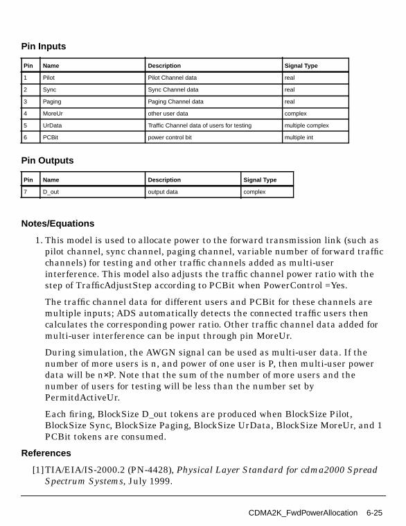
Pin Inputs
Pin Outputs
Notes/Equations
1. This model is used to allocate power to the forward transmission link (such aspilot channel, sync channel, paging channel, variable number of forward trafficchannels) for testing and other traffic channels added as multi-userinterference. This model also adjusts the traffic channel power ratio with thestep of TrafficAdjustStep according to PCBit when PowerControl =Yes.
The traffic channel data for different users and PCBit for these channels aremultiple inputs; ADS automatically detects the connected traffic users thencalculates the corresponding power ratio. Other traffic channel data added formulti-user interference can be input through pin MoreUr.
During simulation, the AWGN signal can be used as multi-user data. If thenumber of more users is n, and power of one user is P, then multi-user powerdata will be n×P. Note that the sum of the number of more users and thenumber of users for testing will be less than the number set byPermitdActiveUr.
Each firing, BlockSize D_out tokens are produced when BlockSize Pilot,BlockSize Sync, BlockSize Paging, BlockSize UrData, BlockSize MoreUr, and 1PCBit tokens are consumed.
References
[1]TIA/EIA/IS-2000.2 (PN-4428), Physical Layer Standard for cdma2000 SpreadSpectrum Systems, July 1999.
Pin Name Description Signal Type
1 Pilot Pilot Channel data real
2 Sync Sync Channel data real
3 Paging Paging Channel data real
4 MoreUr other user data complex
5 UrData Traffic Channel data of users for testing multiple complex
6 PCBit power control bit multiple int
Pin Name Description Signal Type
7 D_out output data complex
CDMA2K_FwdPowerAllocation 6-25

Transmission
CDMA2K_FwdPwrAlloc
Description Power allocator for base station channelsLibrary cdma2000, TransmissionClass SDFCDMA2K_FwdPwrAlloc
Parameters
Name Description Default Sym Type Range
TransmitDiversity transmit diversity enable:NON_TD, TD
NON_TD enum
PilotPowerRatio pilot channel power to totalpower ratio
0.2 real (0, 1) †
SyncPowerRatio sync channel power to totalpower ratio
0.025 real [0, 1)
PagingPowerRatio paging channel power tototal power ratio
0.063 real [0, 1)
TDPilotPowerRatio transmit diversity pilotchannel power to totalpower ratio
0.2 real (0, 1) ifTransmitDiversity=TD
WalshLength length of Walsh code 64 N int2n , n=6,...,11
PermitdActiveUr number of permitted activeusers in forward link
30 int [6, N-3-(N/64)] ifTransmitDiversity = NON_TD; [6,(N-3-(N/64))/2] ifTransmitDiversity = TD
OrthogonalChNum number of the orthogonalchannel to form the noise,in TD mode, it will bedouble of number oforthogonal users
29 int [0,PermitdActiveUr-sizeof(UrData)]ifTransmitDiversity=NON_TD; [0,
2×PermitdActiveUr-1]
PowerControl enable the power control:Yes, No
Yes enum
6-26 CDMA2K_FwdPwrAlloc

Pin Inputs
Pin Outputs
Notes/Equations
1. This model is used to allocate power ratio to the forward transmission link(including pilot channel, transmit diversity pilot channel, sync channel, pagingchannel, variable number of forward traffic channels concerned and othertraffic channels not concerned) and adjust the traffic channel power ratio withthe step of TrafficAdjustStep according to PCBit when PowerControl = Yes.
Traffic channel data for different users and PCBit for these channels aremultiple inputs; ADS can automatically detect the connected traffic users.Orthogonal channel data added for multi-user interference can be importedthrough pin OCN_Ur. If the number of users is n, and the power of one user is P,then multi-user power data will be n×P. Note that the sum of the number ofOCN users and the number of users for the test will be less than the number setby the PermitdActiveUr parameter.
Each firing,
• if TransmitDiversity = NON_TD, 1536 D_out tokens are produced when 1536UrData tokens, 1536 OCN_Ur tokens, and 1 PCBit token are consumed;
TrafficAdjustStep traffic channel poweradjust step
1 real (0, ∞)
IgnoreNum number of initially ignoredfirings
1 int [0, ∞)
† The sum of PilotPowerRatio, SyncPowerRatio, and PagingPowerRatio must be < 1 if TransmitDiversity = NON_TD; the sum ofPilotPowerRatio, SyncPowerRatio, PagingPowerRatio, and TDPilotPowerRatio must be < 1 if TransmitDiversity =TD.
Pin Name Description Signal Type
1 OCN_Ur user data as orthogonal channel noise complex
2 UrData Traffic Channel data of users for testing multiple complex
3 PCBit power control bit multiple int
Pin Name Description Signal Type
4 D_out output data complex
Name Description Default Sym Type Range
CDMA2K_FwdPwrAlloc 6-27

Transmission
• if TransmitDiversity = TD, 3072 D_out tokens are produced when 3072UrData tokens, 3072 OCN_Ur tokens and 1 PCBit token are consumed.
D_out can be determined by:
Each traffic channel, as well as the channels simulated as signal of OCN_Ur,are assumed to have the same power initially. Then if PCBit is 0 the basestation will increase the corresponding traffic channel power ratio at aTrafficAdjustStep value, otherwise the base station will decrease it at aTrafficAdjustStep value. At the same time, the ratio between power of pilotchannel and average power of all traffic channels remains a constant value—the pilot channel power will not be changed when traffic channel powers arechanged.
References
[1]3GPP2 C.S0002_A_1, “Physical Layer Standard for cdma2000 Spread SpectrumSystems Release A-Addendum 1,” Oct. 27, 2000.
[2] 3GPP2 TSG-C Interim Plenary, “Recommended Minimum PerformanceStandards for cdma2000 Spread Spectrum Mobile Stations: Release A,” Nov. 27,2000.
[3] 3GPP2 TSG-C4.1,“Recommended Minimum Performance Standards forcdma2000 Spread Spectrum Base Stations: Release A,” Oct. 26, 2000.
CombinedSignalPower Σ EachChannel RelativeRatio×( )=
6-28 CDMA2K_FwdPwrAlloc
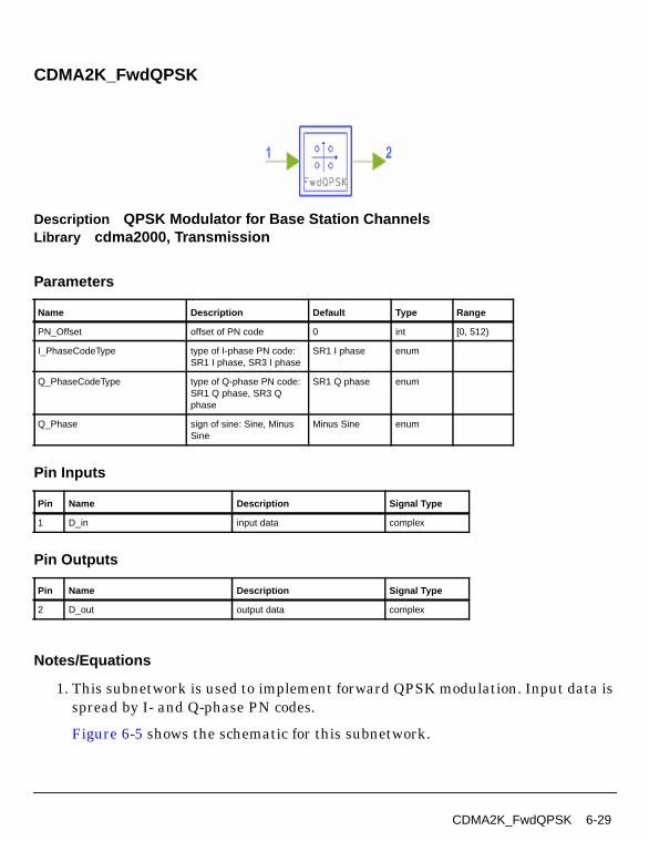
CDMA2K_FwdQPSK
Description QPSK Modulator for Base Station ChannelsLibrary cdma2000, Transmission
Parameters
Pin Inputs
Pin Outputs
Notes/Equations
1. This subnetwork is used to implement forward QPSK modulation. Input data isspread by I- and Q-phase PN codes.
Figure 6-5 shows the schematic for this subnetwork.
Name Description Default Type Range
PN_Offset offset of PN code 0 int [0, 512)
I_PhaseCodeType type of I-phase PN code:SR1 I phase, SR3 I phase
SR1 I phase enum
Q_PhaseCodeType type of Q-phase PN code:SR1 Q phase, SR3 Qphase
SR1 Q phase enum
Q_Phase sign of sine: Sine, MinusSine
Minus Sine enum
Pin Name Description Signal Type
1 D_in input data complex
Pin Name Description Signal Type
2 D_out output data complex
CDMA2K_FwdQPSK 6-29
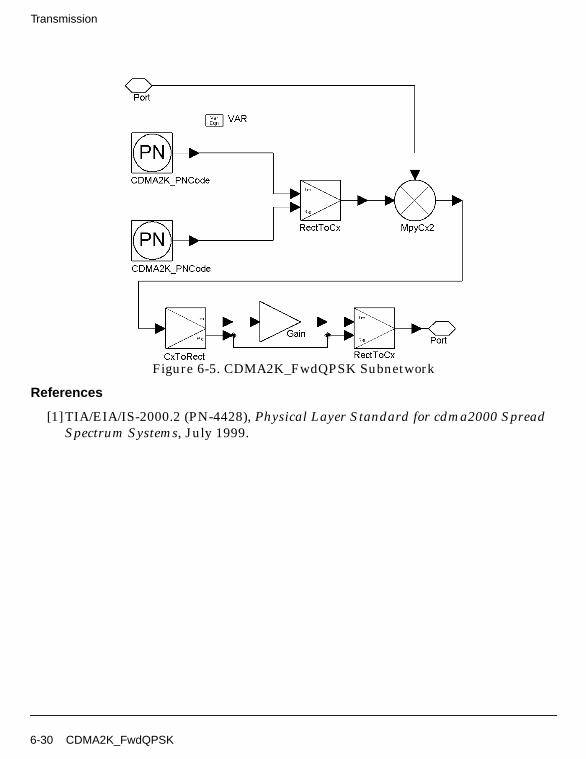
Transmission
Figure 6-5. CDMA2K_FwdQPSK Subnetwork
References
[1]TIA/EIA/IS-2000.2 (PN-4428), Physical Layer Standard for cdma2000 SpreadSpectrum Systems, July 1999.
6-30 CDMA2K_FwdQPSK
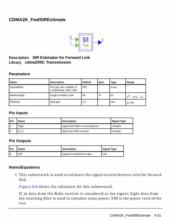
CDMA2K_FwdSIREstimate
Description SIR Estimator for Forward LinkLibrary cdma2000, Transmission
Parameters
Pin Inputs
Pin Outputs
Notes/Equations
1. This subnetwork is used to estimate the signal-to-interference ratio for forwardlink.
Figure 6-6 shows the schematic for this subnetwork.
D_in data from the Rake receiver is considered as the signal; SigIn data fromthe receiving filter is used to calculate noise power; SIR is the power ratio of thetwo.
Name Description Default Sym Type Range
SpreadRate PN chip rate, multiple of1.2288 Mcps: SR1, SR3
SR1 enum
WalshLength length of Walsh code 64 N int2n , n=1,...,11
PilotGain pilot gain 1.0 real (0, ∞)
Pin Name Description Signal Type
1 SigIn signal from filter of receiving end complex
2 D_in data from Rake receiver complex
Pin Name Description Signal Type
3 SIR signal-to-interference ratio real
CDMA2K_FwdSIREstimate 6-31
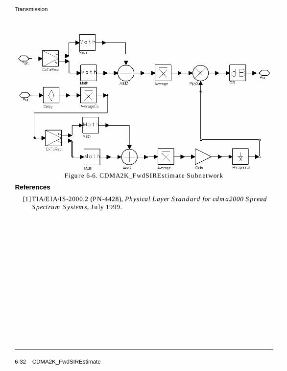
Transmission
Figure 6-6. CDMA2K_FwdSIREstimate Subnetwork
References
[1]TIA/EIA/IS-2000.2 (PN-4428), Physical Layer Standard for cdma2000 SpreadSpectrum Systems, July 1999.
6-32 CDMA2K_FwdSIREstimate
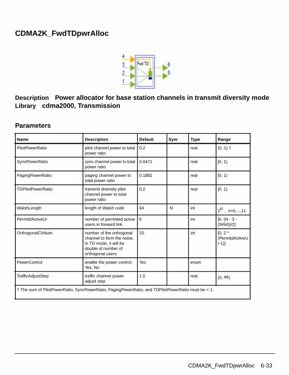
CDMA2K_FwdTDpwrAlloc
Description Power allocator for base station channels in transmit diversity modeLibrary cdma2000, Transmission
Parameters
Name Description Default Sym Type Range
PilotPowerRatio pilot channel power to totalpower ratio
0.2 real (0, 1) †
SyncPowerRatio sync channel power to totalpower ratio
0.0471 real [0, 1)
PagingPowerRatio paging channel power tototal power ratio
0.1882 real [0, 1)
TDPilotPowerRatio transmit diversity pilotchannel power to totalpower ratio
0.2 real [0, 1)
WalshLength length of Walsh code 64 N int2n , n=6,...,11
PermitdActiveUr number of permitted activeusers in forward link
6 int [6, (N - 3 -(N/64))/2]
OrthogonalChNum number of the orthogonalchannel to form the noise,in TD mode, it will bedouble of number oforthogonal users
10 int [0, 2 *(PermitdActiveUr-1)]
PowerControl enable the power control:Yes, No
Yes enum
TrafficAdjustStep traffic channel poweradjust step
1.0 real (0, ∞)
† The sum of PilotPowerRatio, SyncPowerRatio, PagingPowerRatio, and TDPilotPowerRatio must be < 1.
CDMA2K_FwdTDpwrAlloc 6-33
Transmission
Pin Inputs
Pin Outputs
Notes/Equations
1. This subnetwork is used to allocate power ratio to the forward transmissionlink (including pilot channel, transmit diversity pilot, sync channel, pagingchannel, variable number of forward traffic channels concerned and othertraffic channels not concerned) and adjust the traffic channel power ratio withthe step of TrafficAdjustStep according to PCBit when PowerControl = Yes.
The schematic for this subnetwork is shown in Figure 6-7.
Pin Name Description Signal Type
1 MainIn traffic channel data of user for testing that isassociated with the transmit diversity pilot channel
complex
2 TDin traffic channel data of user for testing that isassociated with the transmit diversity pilot channel
complex
3 OCN_Ur user data as orthogonal channel noise complex
4 PCBit power control bit int
Pin Name Description Signal Type
5 MainOut output data of user for testing that is associated withthe transmit diversity pilot channel
complex
6 TDout output data of user for testing that is associated withthe transmit diversity pilot channel
complex
6-34 CDMA2K_FwdTDpwrAlloc
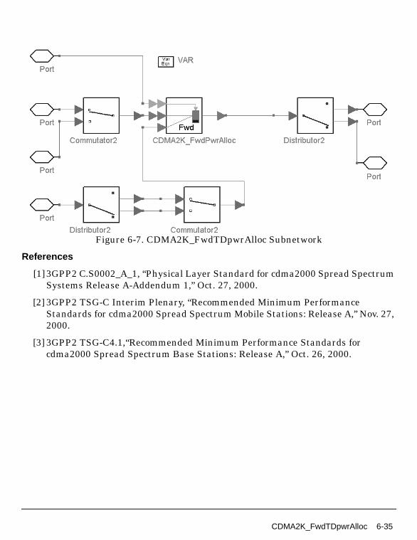
Figure 6-7. CDMA2K_FwdTDpwrAlloc Subnetwork
References
[1]3GPP2 C.S0002_A_1, “Physical Layer Standard for cdma2000 Spread SpectrumSystems Release A-Addendum 1,” Oct. 27, 2000.
[2] 3GPP2 TSG-C Interim Plenary, “Recommended Minimum PerformanceStandards for cdma2000 Spread Spectrum Mobile Stations: Release A,” Nov. 27,2000.
[3] 3GPP2 TSG-C4.1,“Recommended Minimum Performance Standards forcdma2000 Spread Spectrum Base Stations: Release A,” Oct. 26, 2000.
CDMA2K_FwdTDpwrAlloc 6-35
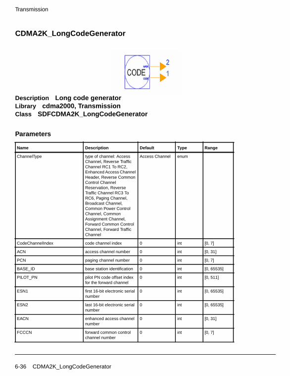
Transmission
CDMA2K_LongCodeGenerator
Description Long code generatorLibrary cdma2000, TransmissionClass SDFCDMA2K_LongCodeGenerator
Parameters
Name Description Default Type Range
ChannelType type of channel: AccessChannel, Reverse TrafficChannel RC1 To RC2,Enhanced Access ChannelHeader, Reverse CommonControl ChannelReservation, ReverseTraffic Channel RC3 ToRC6, Paging Channel,Broadcast Channel,Common Power ControlChannel, CommonAssignment Channel,Forward Common ControlChannel, Forward TrafficChannel
Access Channel enum
CodeChannelIndex code channel index 0 int [0, 7]
ACN access channel number 0 int [0, 31]
PCN paging channel number 0 int [0, 7]
BASE_ID base station identification 0 int [0, 65535]
PILOT_PN pilot PN code offset indexfor the forward channel
0 int [0, 511]
ESN1 first 16-bit electronic serialnumber
0 int [0, 65535]
ESN2 last 16-bit electronic serialnumber
0 int [0, 65535]
EACN enhanced access channelnumber
0 int [0, 31]
FCCCN forward common controlchannel number
0 int [0, 7]
6-36 CDMA2K_LongCodeGenerator

Pin Outputs
Notes/Equations
1. This model is used to generate m-sequence bits with the period of 242-1 bit long.The output is the sequence of logic value 0 or 1. The initial register status is:
{00,0000000000,0000000000,0000000000,0000000001}(from the 42nd register to the first one) and shift 41 times.
There are 11 kinds of masks in IS-2000, each PN chip of the long code isgenerated by the modulo-2 inner product of a 42-bit mask and the 42-bit statevector of the sequence generator.
While mask 0 is not supported by this model, a ConstInt component (NumericSources library) with Level=0 can be used as a substitute.
Each firing, 1 LgCode and 42 T_Mask tokens are produced.
References
[1]TIA/EIA/IS-2000.2 (PN-4428), Physical Layer Standard for cdma2000 SpreadSpectrum Systems, July 1999.
RCCCN reverse common controlchannel number
0 int [0, 31]
SLOT_OFFSET slot offset for enhancedaccess channel
0 int [0, 511]
BCN broadcast channel number 0 int [0, 7]
CPCCN common power controlchannel number
0 int [0, 3]
CACN common assignmentchannel number
0 int [0, 7]
Pin Name Description Signal Type
1 LgCode long code int
2 T_Mask mask value for test int
Name Description Default Type Range
CDMA2K_LongCodeGenerator 6-37
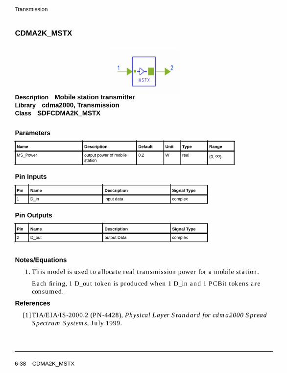
Transmission
CDMA2K_MSTX
Description Mobile station transmitterLibrary cdma2000, TransmissionClass SDFCDMA2K_MSTX
Parameters
Pin Inputs
Pin Outputs
Notes/Equations
1. This model is used to allocate real transmission power for a mobile station.
Each firing, 1 D_out token is produced when 1 D_in and 1 PCBit tokens areconsumed.
References
[1]TIA/EIA/IS-2000.2 (PN-4428), Physical Layer Standard for cdma2000 SpreadSpectrum Systems, July 1999.
Name Description Default Unit Type Range
MS_Power output power of mobilestation
0.2 W real (0, ∞)
Pin Name Description Signal Type
1 D_in input data complex
Pin Name Description Signal Type
2 D_out output Data complex
6-38 CDMA2K_MSTX

CDMA2K_PCBgenerator
Description Power control bit generatorLibrary cdma2000, TransmissionClass SDFCDMA2K_PCBgenerator
Parameters
Pin Inputs
Pin Outputs
Notes/Equations
1. This model is used to generate the power control bit.
Name Description Default Type Range
OuterLoop outer loop power controlenable: ENABLE,DISABLE
DISABLE enum
SIR_Threshold signal-to-interference ratiorequired
0 real (-∞, ∞)
SIR_AdjustStep signal-to-interference ratioadjustment
1.0 0.2 0.1 0.02 real array (0, ∞)
FER_Threshold minimum frame error raterequired
0.007 real [0, 1)
IgnoreNum number of initially ignoredfirings
1 int [1, ∞)
Pin Name Description Signal Type
1 SIR signal interference ratio real
2 FrmErr frame error indicator of current frame int
Pin Name Description Signal Type
3 PCBit Power Control Bit int
CDMA2K_PCBgenerator 6-39

Transmission
Each firing, 1 PCBit token is produced when 1 SIR token and 1 FrmErr tokenare consumed.
As shown in Figure 6-8, the closed loop power control includes an inner and anouter loop.
Figure 6-8. Power Control Block Diagram
References
[1]3GPP2 C.S0002_A_1, “Physical Layer Standard for cdma2000 Spread SpectrumSystems Release A-Addendum 1,” Oct. 27, 2000.
[2] 3GPP2 TSG-C Interim Plenary, “Recommended Minimum PerformanceStandards for cdma2000 Spread Spectrum Mobile Stations: Release A,” Nov. 27,2000.
[3] 3GPP2 TSG-C4.1,“Recommended Minimum Performance Standards forcdma2000 Spread Spectrum Base Stations: Release A,” Oct. 26, 2000.
FER_Measure
SIR data
SIR_Threshold_Adjust
DecisionTarget SIR
Power_Control_Bit
Outer Loop
Inner Loop
6-40 CDMA2K_PCBgenerator
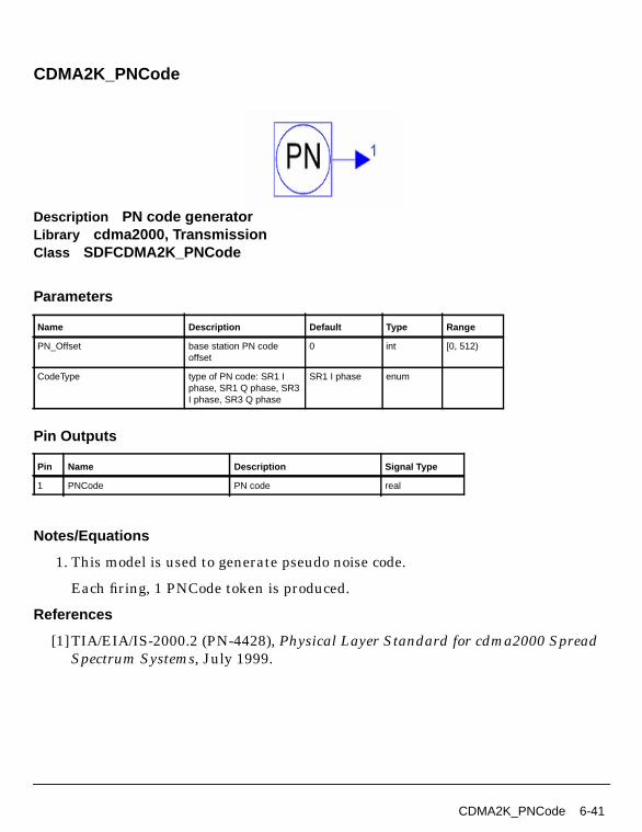
CDMA2K_PNCode
Description PN code generatorLibrary cdma2000, TransmissionClass SDFCDMA2K_PNCode
Parameters
Pin Outputs
Notes/Equations
1. This model is used to generate pseudo noise code.
Each firing, 1 PNCode token is produced.
References
[1]TIA/EIA/IS-2000.2 (PN-4428), Physical Layer Standard for cdma2000 SpreadSpectrum Systems, July 1999.
Name Description Default Type Range
PN_Offset base station PN codeoffset
0 int [0, 512)
CodeType type of PN code: SR1 Iphase, SR1 Q phase, SR3I phase, SR3 Q phase
SR1 I phase enum
Pin Name Description Signal Type
1 PNCode PN code real
CDMA2K_PNCode 6-41

Transmission
CDMA2K_PNCode_U
Description PN code generator, spec. 3GPP2 C.S0002-A-1, Oct. 2000.Library cdma2000, TransmissionClass SDFCDMA2K_PNCode_U
Parameters
Pin Outputs
Notes/Equations
1. This model is used to generate pseudo noise (PN) code.
Each firing, 1 PNCode token is produced.
• For SR1 I phase (Forward SR1 I phase, Forward MC SR3 I phase andReverse SR1 I phase), PN code is a 215-1 bits M-sequence inserted by another0, the polynomial is:
The maximum length linear feedback shift register sequence {i(n)} based onthe above polynomials are of length 215-1 and can be generated by thefollowing linear recursions:
Name Description Default Type Range
PN_Offset base station PN codeoffset
0 int [0, 512)
CodeType type of PN code: SR1 Iphase, SR1 Q phase, SR3I phase, SR3 Q phase
SR1 I phase enum
Pin Name Description Signal Type
1 PNCode PN code real
PI x( ) x15 x13 x9 x8 x7 x51+ + + + + +=
6-42 CDMA2K_PNCode_U

where additions are modulo-2. In order to obtain the I sequences of period215, a 0 is inserted in {i(n)} after 14 consecutive 0 outputs.
• For SR1 Q phase (Forward SR1 Q phase, Forward MC SR3 Q phase andReverse SR1 Q phase), PN code is a 215-1 bits M-sequence inserted byanother 0, the polynomial is:
The maximum length linear feedback shift register sequence {q(n)} based onthe above polynomials are 215-1 and can be generated by the following linearrecursions:
where additions are modulo-2. In order to obtain the I sequences of period215, a 0 is inserted in {q(n)} after 14 consecutive 0 outputs.
• For SR3 I phase (Forward DS SR3) and SR3 Q phase (Forward DS SR3), PNcodes are both truncated M-sequence of length 220-1 bits and truncating after3×215 chips, the polynomial is:
The maximum length linear feedback shift register sequence {b(n)} based onthe above polynomials are 220-1 and can be generated by the following linearrecursions:
where additions are modulo-2. The I and Q PN sequences are both formedfrom this maximal length sequence of 220-1 using different starting positionsand truncating the sequence after 3×215 chips.
The starting position of the I PN sequence is such that the first chip is the 1after the 19 consecutive 0s. The starting position of the Q PN sequence is thestarting position of the I PN sequence delayed by 219 chips.
i n( ) i n 15–( ) i n 10–( ) i n 8–( ) i n 7–( ) i n 6–( ) i n 2–( )⊕ ⊕ ⊕ ⊕ ⊕=
PQ x( ) x15 x12 x11 x10 x6 x5 x4 x31+ + + + + + + +=
q n( ) q n 15–( ) q n 12–( ) q n 11–( ) q n 10–( ) q n 9–( )q n 5–( ) q n 4–( ) q n 3–( )
⊕ ⊕ ⊕ ⊕⊕ ⊕ ⊕
=
P x( ) x20 x9 x5 x31+ + + +=
b n( ) b n 20–( ) b n 17–( ) b n 15–( ) b n 11–( )⊕ ⊕ ⊕=
CDMA2K_PNCode_U 6-43

Transmission
The mobile station will align the I and Q PN sequences such that the first 20chips of the I and Q PN sequences on every even second mark as referencedto the transmit time reference are '1000 0000 0001 0001 0100' and '1001 00000010 0100 0101'.
References
1. 3GPP2 C.S0002_A_1, “Physical Layer Standard for cdma2000 Spread SpectrumSystems Release A-Addendum 1,” Oct. 27, 2000.
6-44 CDMA2K_PNCode_U
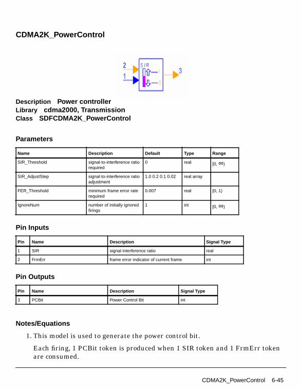
CDMA2K_PowerControl
Description Power controllerLibrary cdma2000, TransmissionClass SDFCDMA2K_PowerControl
Parameters
Pin Inputs
Pin Outputs
Notes/Equations
1. This model is used to generate the power control bit.
Each firing, 1 PCBit token is produced when 1 SIR token and 1 FrmErr tokenare consumed.
Name Description Default Type Range
SIR_Threshold signal-to-interference ratiorequired
0 real [0, ∞)
SIR_AdjustStep signal-to-interference ratioadjustment
1.0 0.2 0.1 0.02 real array
FER_Threshold minimum frame error raterequired
0.007 real [0, 1)
IgnoreNum number of initially ignoredfirings
1 int [0, ∞)
Pin Name Description Signal Type
1 SIR signal interference ratio real
2 FrmErr frame error indicator of current frame int
Pin Name Description Signal Type
3 PCBit Power Control Bit int
CDMA2K_PowerControl 6-45
Transmission
References
[1]TIA/EIA/IS-2000.2 (PN-4428), Physical Layer Standard for cdma2000 SpreadSpectrum Systems, July 1999.
6-46 CDMA2K_PowerControl

CDMA2K_QuasiOrthMask
Description Quasi-orthogonal mask generatorLibrary cdma2000, TransmissionClass SDFCDMA2K_QuasiOrthMask
Parameters
Pin Outputs
Notes/Equation
1. This model is used to generate quasi-orthogonal mask symbol.
Each firing, 4 D_out tokens are produced.
References
[1]TIA/EIA/IS-2000.2 (PN-4428), Physical Layer Standard for cdma2000 SpreadSpectrum Systems, July 1999.
Name Description Default Type
SpreadRate PN chip rate; multiple of1.2288 Mcps: SR1, SR3MC, SR3 DS
SR1 enum
FunctionIndex quasi-orthogonal functionindex: Function 0, Function1, Function 2, Function 3
Function 0 enum
Pin Name Description Signal Type
1 D_out quasi-orthogonal mask symbol real
CDMA2K_QuasiOrthMask 6-47
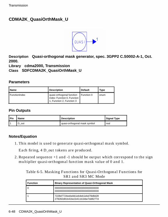
Transmission
CDMA2K_QuasiOrthMask_U
Description Quasi-orthogonal mask generator, spec. 3GPP2 C.S0002-A-1, Oct.2000.Library cdma2000, TransmissionClass SDFCDMA2K_QuasiOrthMask_U
Parameters
Pin Outputs
Notes/Equation
1. This model is used to generate quasi-orthogonal mask symbol.
Each firing, 4 D_out tokens are produced.
2. Repeated sequence +1 and -1 should be output which correspond to the signmultiplier quasi-orthogonal function mask value of 0 and 1.
Name Description Default Type
FunctionIndex quasi-orthogonal functionindex: Function 0, Function1, Function 2, Function 3
Function 0 enum
Pin Name Description Signal Type
1 D_out quasi-orthogonal mask symbol real
Table 6-5. Masking Functions for Quasi-Orthogonal Functions forSR1 and SR3 MC Mode
Function Binary Representation of Quasi-Orthogonal Mask
0 0000000000000000000000000000000000000000000000000000000000000000
1 7228d7724eebebb1eb4eb1ebd78d8d28278282d81b41be1b411b1bbe7dd8277d
6-48 CDMA2K_QuasiOrthMask_U

References
[1]3GPP2 C.S0002_A_1, “Physical Layer Standard for cdma2000 Spread SpectrumSystems Release A-Addendum 1,” Oct. 27, 2000.
2 114b1e4444e14beeee4be144bbe1b4eedd872d77882d78dd2287d277772d87dd
3 1724bd71b28118d48ebddb172b187eb2e7d4b27ebd8ee82481b22be7dbe871bd
Table 6-5. Masking Functions for Quasi-Orthogonal Functions forSR1 and SR3 MC Mode
Function Binary Representation of Quasi-Orthogonal Mask
CDMA2K_QuasiOrthMask_U 6-49
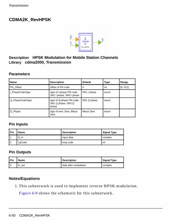
Transmission
CDMA2K_RevHPSK
Description HPSK Modulation for Mobile Station ChannelsLibrary cdma2000, Transmission
Parameters
Pin Inputs
Pin Outputs
Notes/Equations
1. This subnetwork is used to implement reverse HPSK modulation.
Figure 6-9 shows the schematic for this subnetwork.
Name Description Default Type Range
PN_Offset offset of PN code 0 int [0, 512)
I_PhaseCodeType type of I-phase PN code:SR1 I phase, SR3 I phase
SR1 I phase enum
Q_PhaseCodeType type of Q-phase PN code:SR1 Q phase, SR3 Qphase
SR1 Q phase enum
Q_Phase sign of sine: Sine, MinusSine
Minus Sine enum
Pin Name Description Signal Type
1 D_in input data complex
2 LgCode long code int
Pin Name Description Signal Type
3 D_out data after modulation complex
6-50 CDMA2K_RevHPSK
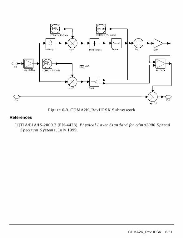
Figure 6-9. CDMA2K_RevHPSK Subnetwork
References
[1]TIA/EIA/IS-2000.2 (PN-4428), Physical Layer Standard for cdma2000 SpreadSpectrum Systems, July 1999.
CDMA2K_RevHPSK 6-51
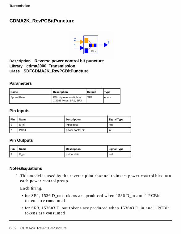
Transmission
CDMA2K_RevPCBitPuncture
Description Reverse power control bit punctureLibrary cdma2000, TransmissionClass SDFCDMA2K_RevPCBitPuncture
Parameters
Pin Inputs
Pin Outputs
Notes/Equations
1. This model is used by the reverse pilot channel to insert power control bits intoeach power control group.
Each firing,
• for SR1, 1536 D_out tokens are produced when 1536 D_in and 1 PCBittokens are consumed
• for SR3, 1536×3 D_out tokens are produced when 1536×3 D_in and 1 PCBittokens are consumed
Name Description Default Type
SpreadRate PN chip rate; multiple of1.2288 Mcps: SR1, SR3
SR1 enum
Pin Name Description Signal Type
1 D_in input data real
2 PCBit power contol bit int
Pin Name Description Signal Type
3 D_out output data real
6-52 CDMA2K_RevPCBitPuncture
References
[1]TIA/EIA/IS-2000.2 (PN-4428), Physical Layer Standard for cdma2000 SpreadSpectrum Systems, July 1999.
CDMA2K_RevPCBitPuncture 6-53
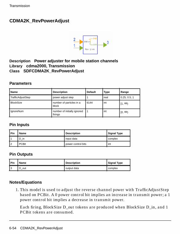
Transmission
CDMA2K_RevPowerAdjust
Description Power adjuster for mobile station channelsLibrary cdma2000, TransmissionClass SDFCDMA2K_RevPowerAdjust
Parameters
Pin Inputs
Pin Outputs
Notes/Equations
1. This model is used to adjust the reverse channel power with TrafficAdjustStepbased on PCBit. A 0 power control bit implies an increase in transmit power; a 1power control bit implies a decrease in transmit power.
Each firing, BlockSize D_out tokens are produced when BlockSize D_in, and 1PCBit tokens are consumed.
Name Description Default Type Range
TrafficAdjustStep power adjust step 1 real 0.25, 0.5, 1
BlockSize number of particles in ablock
6144 int [1, ∞)
IgnoreNum number of initially ignoredfirings
1 int [0, ∞)
Pin Name Description Signal Type
1 D_in input data complex
2 PCBit power control bits int
Pin Name Description Signal Type
3 D_out output data complex
6-54 CDMA2K_RevPowerAdjust
References
[1]TIA/EIA/IS-2000.2 (PN-4428), Physical Layer Standard for cdma2000 SpreadSpectrum Systems, July 1999.
CDMA2K_RevPowerAdjust 6-55
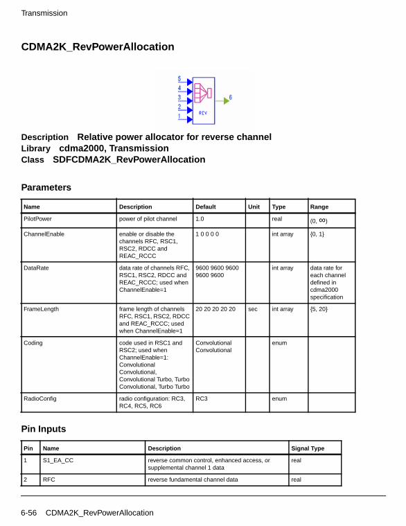
Transmission
CDMA2K_RevPowerAllocation
Description Relative power allocator for reverse channelLibrary cdma2000, TransmissionClass SDFCDMA2K_RevPowerAllocation
Parameters
Pin Inputs
Name Description Default Unit Type Range
PilotPower power of pilot channel 1.0 real (0, ∞)
ChannelEnable enable or disable thechannels RFC, RSC1,RSC2, RDCC andREAC_RCCC
1 0 0 0 0 int array {0, 1}
DataRate data rate of channels RFC,RSC1, RSC2, RDCC andREAC_RCCC; used whenChannelEnable=1
9600 9600 96009600 9600
int array data rate foreach channeldefined incdma2000specification
FrameLength frame length of channelsRFC, RSC1, RSC2, RDCCand REAC_RCCC; usedwhen ChannelEnable=1
20 20 20 20 20 sec int array {5, 20}
Coding code used in RSC1 andRSC2; used whenChannelEnable=1:ConvolutionalConvolutional,Convolutional Turbo, TurboConvolutional, Turbo Turbo
ConvolutionalConvolutional
enum
RadioConfig radio configuration: RC3,RC4, RC5, RC6
RC3 enum
Pin Name Description Signal Type
1 S1_EA_CC reverse common control, enhanced access, orsupplemental channel 1 data
real
2 RFC reverse fundamental channel data real
6-56 CDMA2K_RevPowerAllocation

Pin Outputs
Notes/Equations
1. This model is used to allocate relative power for the reverse link (includingreverse pilot channel, reverse fundamental channel, reverse supplementalchannels, reverse dedicated control channel, enhanced access channel andreverse common control channels).
According to [1], when the reverse common control channel or enhanced accesschannel is used, the only additional channel is the reverse pilot channel. Binarysignals from five inputs are represented as ±1, with the mapping +1 for 0and −1 for 1, unused channels are represented with a 0 value.
Each firing, 1 Sigout token is produced when 1 S1_EA_CC, 1 RFC, 1 RDCC,1 RPC and 1 RSC2 tokens are consumed.
2. This model does not support 10/40/80 msec frame length.CDMA2K_RevPowerAllocation_U is a more general model based on updatedspecifications that can be used for 5/10/20/40/80 msec frame length.
References
[1]TIA/EIA/IS-2000.2 (PN-4428), Physical Layer Standard for cdma2000 SpreadSpectrum Systems, July 1999.
3 RDCC reverse dedicated control channel data real
4 RPC reverse pilot channel data real
5 RSC2 reverse supplemental chennal 2 data real
Pin Name Description Signal Type
6 SigOut output data complex
Pin Name Description Signal Type
CDMA2K_RevPowerAllocation 6-57
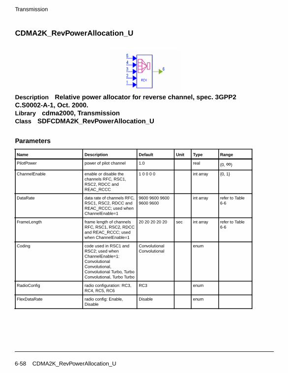
Transmission
CDMA2K_RevPowerAllocation_U
Description Relative power allocator for reverse channel, spec. 3GPP2C.S0002-A-1, Oct. 2000.Library cdma2000, TransmissionClass SDFCDMA2K_RevPowerAllocation_U
Parameters
Name Description Default Unit Type Range
PilotPower power of pilot channel 1.0 real (0, ∞)
ChannelEnable enable or disable thechannels RFC, RSC1,RSC2, RDCC andREAC_RCCC
1 0 0 0 0 int array {0, 1}
DataRate data rate of channels RFC,RSC1, RSC2, RDCC andREAC_RCCC; used whenChannelEnable=1
9600 9600 96009600 9600
int array refer to Table6-6
FrameLength frame length of channelsRFC, RSC1, RSC2, RDCCand REAC_RCCC; usedwhen ChannelEnable=1
20 20 20 20 20 sec int array refer to Table6-6
Coding code used in RSC1 andRSC2; used whenChannelEnable=1:ConvolutionalConvolutional,Convolutional Turbo, TurboConvolutional, Turbo Turbo
ConvolutionalConvolutional
enum
RadioConfig radio configuration: RC3,RC4, RC5, RC6
RC3 enum
FlexDataRate radio config: Enable,Disable
Disable enum
6-58 CDMA2K_RevPowerAllocation_U
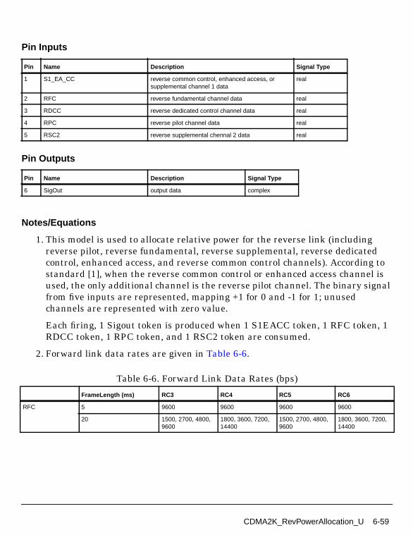
Pin Inputs
Pin Outputs
Notes/Equations
1. This model is used to allocate relative power for the reverse link (includingreverse pilot, reverse fundamental, reverse supplemental, reverse dedicatedcontrol, enhanced access, and reverse common control channels). According tostandard [1], when the reverse common control or enhanced access channel isused, the only additional channel is the reverse pilot channel. The binary signalfrom five inputs are represented, mapping +1 for 0 and -1 for 1; unusedchannels are represented with zero value.
Each firing, 1 Sigout token is produced when 1 S1EACC token, 1 RFC token, 1RDCC token, 1 RPC token, and 1 RSC2 token are consumed.
2. Forward link data rates are given in Table 6-6.
Pin Name Description Signal Type
1 S1_EA_CC reverse common control, enhanced access, orsupplemental channel 1 data
real
2 RFC reverse fundamental channel data real
3 RDCC reverse dedicated control channel data real
4 RPC reverse pilot channel data real
5 RSC2 reverse supplemental chennal 2 data real
Pin Name Description Signal Type
6 SigOut output data complex
Table 6-6. Forward Link Data Rates (bps)
FrameLength (ms) RC3 RC4 RC5 RC6
RFC 5 9600 9600 9600 9600
20 1500, 2700, 4800,9600
1800, 3600, 7200,14400
1500, 2700, 4800,9600
1800, 3600, 7200,14400
CDMA2K_RevPowerAllocation_U 6-59
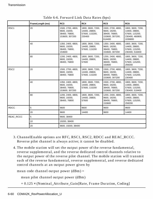
Transmission
3. ChannelEnable options are RFC, RSC1, RSC2, RDCC and REAC_RCCC.Reverse pilot channel is always active; it cannot be disabled.
4. The mobile station will set the output power of the reverse fundamental,reverse supplemental, and the reverse dedicated control channels relative tothe output power of the reverse pilot channel. The mobile station will transmiteach of the reverse fundamental, reverse supplemental, and reverse dedicatedcontrol channels at an output power given by
mean code channel output power (dBm) =
mean pilot channel output power (dBm)
+ 0.125 × (Nominal_Attribute_Gain[Rate, Frame Duration, Coding]
RSC1 20 1500, 2700, 4800,9600, 19200,38400, 76800,153600, 307200
1800, 3600, 7200,14400, 28800,57600, 115200,230400
1500, 2700, 4800,9600, 19200,38400, 76800,153600, 307200,614400
1800, 3600, 7200,14400, 28800,57600, 115200,230400, 460800,1036800
40 1350, 2400, 4800,9600, 19200,38400, 76800,153600
1800, 3600, 7200,14400, 28800,57600, 115200
1350, 2400, 4800,9600, 19200,38400, 76800,153600, 307200
1800, 3600, 7200,14400, 28800,57600, 115200,230400, 518400
80 1200, 2400, 4800,9600, 19200,38400, 76800
1800, 3600, 7200,14400, 28800,57600
1200, 2400, 4800,9600, 19200,38400, 76800,153600
1800, 3600, 7200,14400, 28800,57600, 115200,259200
RSC2 20 1500, 2700, 4800,9600, 19200,38400, 76800
1800, 3600, 7200,14400, 28800,57600, 115200
1500, 2700, 4800,9600, 19200,38400, 76800,153600, 307200
1800, 3600, 7200,14400, 28800,57600, 115200,230400
40 1350, 2400, 4800,9600, 19200,38400, 76800,153600, 307200
1800, 3600, 7200,14400, 28800,57600, 115200
1500, 2700, 4800,9600, 19200,38400, 76800,153600, 307200
1800, 3600, 7200,14400, 28800,57600, 115200,230400, 518400
80 1200, 2400, 4800,9600, 19200,38400, 76800
1800, 3600, 7200,14400, 28800,57600
1200, 2400, 4800,9600, 19200,38400, 76800,153600
1800, 3600, 7200,14400, 28800,57600, 115200,259200
RDCC 5 9600 9600 9600 9600
20 9600 14400 9600 14400
REAC_RCCC 5 9600, 38400
10 19200, 38400
20 9600, 19200, 38400
Table 6-6. Forward Link Data Rates (bps)
FrameLength (ms) RC3 RC4 RC5 RC6
6-60 CDMA2K_RevPowerAllocation_U

+ Attribute_Adjustment_Gain[Rate, Frame Duration, Coding]
+ Reverse_Channel_Adjustment_Gain[Channel]
- Multiple_Channel_Adjustment_Gain[Channel]
+ RLGAIN_TRAFFIC_PILOTs
+ RLGAIN_SCH_PILOT[Channel]s).
where Channel identifies the fundamental, the dedicated control, and eachsupplemental channel.
The mobile station will maintain a reverse link nominal attribute gain tablecontaining the nominal reverse fundamental, reverse supplemental, or reversededicated control channel power relative to the reverse pilot channel power foreach transmission rate, frame duration, and coding rate supported by themobile station. The mobile station will use the values given in Table 6-7.
Table 6-7. Reverse Link Nominal Attribute Gain Table
Data Rate (bps)Frame Length(ms) Coding
NominalAttribute Gain
PilotReferenceLevel
TargetError Rate
1200 80 Convolutional -56 0 0.05
1350 40 Convolutional -54 0 0.05
1500 20 Convolutional -47 0 0.01
1800 20 Convolutional -42 3 0.01
1800 40 or 80 Convolutional -45 3 0.05
2400 40 or 80 Convolutional -30 0 0.05
2700 20 Convolutional -22 0 0.01
3600 20 Convolutional -13 3 0.01
3600 40 or 80 Convolutional -17 3 0.05
4800 20 Convolutional -2 0 0.01
4800 40 or 80 Convolutional -3 0 0.05
7200 20 Convolutional 15 3 0.01
7200 40 or 80 Convolutional 10 3 0.05
9600 20 Convolutional 30 0 0.01
9600 40 or 80 Convolutional 24 0 0.05
9600 (RC 3 and 5) 5 Convolutional 58 0 0.01
9600 (RC 4 and 6) 5 Convolutional 54 3 0.01
14400 20 Convolutional 44 3 0.01
14400 40 or 80 Convolutional 40 3 0.05
CDMA2K_RevPowerAllocation_U 6-61

Transmission
The mobile station will maintain a reverse link attribute adjustment gain tablecontaining an offset relative to the reverse pilot channel power for each
19200 20, 40 or 80 Convolutional 50 1 0.05
28800 20, 40 or 80 Convolutional 56 11 0.05
38400 20, 40 or 80 Convolutional 60 11 0.05
57600 20, 40 or 80 Convolutional 72 18 0.05
76800 20, 40 or 80 Convolutional 72 21 0.05
115200 20, 40 or 80 Convolutional 80 32 0.05
153600 20, 40 or 80 Convolutional 84 36 0.05
230400 20 or 40 Convolutional 88 46 0.05
259200 80 Convolutional 96 50 0.05
307200 20 or 40 Convolutional 96 54 0.05
460800 20 Convolutional 104 61 0.05
518400 40 Convolutional 104 64 0.05
614400 20 Convolutional 112 68 0.05
1036800 20 Convolutional 128 83 0.05
4800 80 Turbo 2 0 0.05
7200 80 Turbo 24 0 0.05
9600 40 or 80 Turbo 34 0 0.05
14400 40 or 80 Turbo 42 0 0.05
19200 20, 40 or 80 Turbo 44 2 0.05
28800 20, 40 or 80 Turbo 52 9 0.05
38400 20, 40 or 80 Turbo 56 10 0.05
57600 20, 40 or 80 Turbo 64 19 0.05
76800 20, 40 or 80 Turbo 68 19 0.05
115200 20, 40 or 80 Turbo 76 29 0.05
153600 20, 40 or 80 Turbo 76 33 0.05
230400 20 or 40 Turbo 88 39 0.05
259200 80 Turbo 88 48 0.05
307200 20 or 40 Turbo 88 50 0.05
460800 20 Turbo 104 54 0.05
518400 40 Turbo 108 56 0.05
614400 20 Turbo 112 58 0.05
1036800 20 Turbo 125 78 0.05
Table 6-7. Reverse Link Nominal Attribute Gain Table
Data Rate (bps)Frame Length(ms) Coding
NominalAttribute Gain
PilotReferenceLevel
TargetError Rate
6-62 CDMA2K_RevPowerAllocation_U

transmission rate, frame duration, and coding rate supported by the mobilestation. The mobile station will initialize each entry in this table to 0. Themobile station will maintain a reverse channel adjustment gain tablecontaining an offset relative to the reverse pilot channel power for each reverselink code channel supported by the mobile station. The mobile station willinitialize each entry in this table to 0.
The adjustment RLGAIN_SCH_PILOT[Channel]s is valid for the reversesupplemental channel.
If the mobile station is transmitting on only one code channel in addition to thereverse pilot channel, the mobile station will setMultiple_Channel_Adjustment_Gain[Channel] to 0 for all code channels.
If the mobile station is transmitting on two or more code channels in addition tothe reverse pilot channel, the mobile station will setMultiple_Channel_Adjustment_Gain[Channel] for each channel as follows:
• let Max_Channel identify the code channel with the highestPilot_Reference_Level among the code channels on which the mobile stationis transmitting.
• set Multiple_Channel_Adjustment_Gain[Max_Channel] to 0.
• for all other code channels, set Multiple_Channel_Adjustment_Gain[Channel] to Pilot_Reference_Level[Max_Channel] -Pilot_Reference_Level[Channel].
5. The mobile station will set the output power of the enhanced access channelheader, the enhanced access channel data, and the reverse common controlchannel data relative to the output power of the reverse pilot channel. Themobile station will transmit the enhanced access channel header, enhancedaccess channel data, and reverse common control channel data at an outputpower given by
mean code channel output power (dBm) =
mean pilot channel output power (dBm)
+ 0.125 × (Nominal_Reverse_Common_Channel_Attribute_Gain [Rate,Frame Duration])
+ 0.125 × RLGAIN_COMMON_PILOT s.
The mobile station will maintain a nominal reverse common channel attributegain table containing the relative header gain for the enhanced access channel
CDMA2K_RevPowerAllocation_U 6-63

Transmission
header, and the relative data gain for the enhanced access channel data andreverse common channel data for each transmission rate and frame durationsupported by the mobile station. The mobile station will use the values given inTable 6-8.
References
[1]3GPP2 C.S0002_A_1, “Physical Layer Standard for cdma2000 Spread SpectrumSystems Release A-Addendum 1,” Oct. 27, 2000.
Table 6-8. Nominal Reverse Common Channel Attribute Gain Table
Data Rate (bps) Frame Length (ms)Nominal Reverse Common ChannelAttribute Gain
9600 5(Header) 50
9600 20 30
19200 10 64
19200 20 50
38400 5 88
38400 10 80
38400 20 72
6-64 CDMA2K_RevPowerAllocation_U
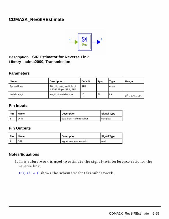
CDMA2K_RevSIREstimate
Description SIR Estimator for Reverse LinkLibrary cdma2000, Transmission
Parameters
Pin Inputs
Pin Outputs
Notes/Equations
1. This subnetwork is used to estimate the signal-to-interference ratio for thereverse link.
Figure 6-10 shows the schematic for this subnetwork.
Name Description Default Sym Type Range
SpreadRate PN chip rate, multiple of1.2288 Mcps: SR1, SR3
SR1 enum
WalshLength length of Walsh code 16 N int2n , n=1,...,11
Pin Name Description Signal Type
1 D_in data from Rake receiver complex
Pin Name Description Signal Type
2 SIR signal interference ratio real
CDMA2K_RevSIREstimate 6-65
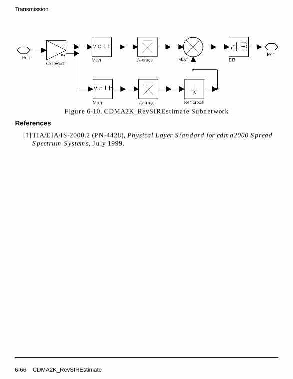
Transmission
Figure 6-10. CDMA2K_RevSIREstimate Subnetwork
References
[1]TIA/EIA/IS-2000.2 (PN-4428), Physical Layer Standard for cdma2000 SpreadSpectrum Systems, July 1999.
6-66 CDMA2K_RevSIREstimate
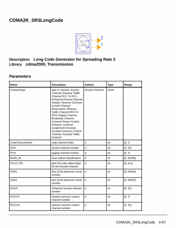
CDMA2K_SR3LongCode
Description Long Code Generator for Spreading Rate 3Library cdma2000, Transmission
Parameters
Name Description Default Type Range
ChannelType type of channel: AccessChannel, Reverse TrafficChannel RC1 To RC2,Enhanced Access ChannelHeader, Reverse CommonControl ChannelReservation, ReverseTraffic Channel RC3 ToRC6, Paging Channel,Broadcast Channel,Common Power ControlChannel, CommonAssignment Channel,Forward Common ControlChannel, Forward TrafficChannel
Access Channel enum
CodeChannelIndex code channel index 0 int [0, 7]
ACN access channel number 0 int [0, 31]
PCN paging channel number 0 int [0, 7]
BASE_ID base station identification 0 int [0, 65535]
PILOT_PN pilot PN code offset indexfor the forward channel
0 int [0, 511]
ESN1 first 16-bit electronic serialnumber
0 int [0, 65535]
ESN2 last 16-bit electronic serialnumber
0 int [0, 65535]
EACN enhanced access channelnumber
0 int [0, 31]
FCCCN forward common controlchannel number
0 int [0, 7]
RCCCN reverse common controlchannel number
0 int [0, 31]
CDMA2K_SR3LongCode 6-67
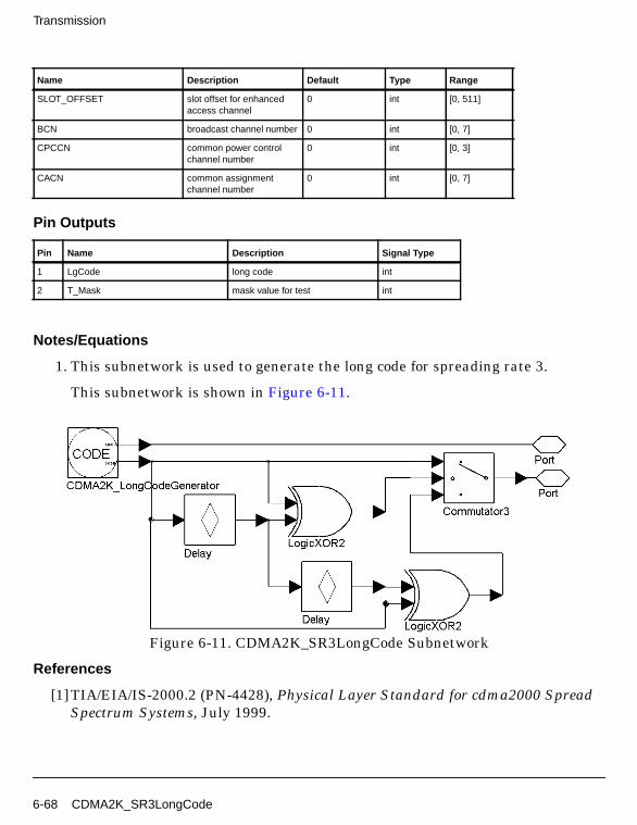
Transmission
Pin Outputs
Notes/Equations
1. This subnetwork is used to generate the long code for spreading rate 3.
This subnetwork is shown in Figure 6-11.
Figure 6-11. CDMA2K_SR3LongCode Subnetwork
References
[1]TIA/EIA/IS-2000.2 (PN-4428), Physical Layer Standard for cdma2000 SpreadSpectrum Systems, July 1999.
SLOT_OFFSET slot offset for enhancedaccess channel
0 int [0, 511]
BCN broadcast channel number 0 int [0, 7]
CPCCN common power controlchannel number
0 int [0, 3]
CACN common assignmentchannel number
0 int [0, 7]
Pin Name Description Signal Type
1 LgCode long code int
2 T_Mask mask value for test int
Name Description Default Type Range
6-68 CDMA2K_SR3LongCode
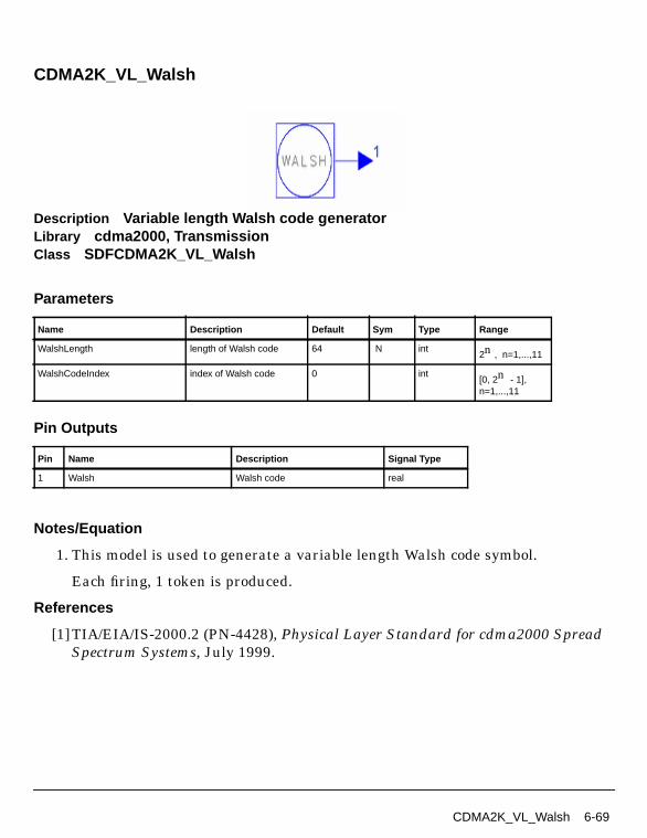
CDMA2K_VL_Walsh
Description Variable length Walsh code generatorLibrary cdma2000, TransmissionClass SDFCDMA2K_VL_Walsh
Parameters
Pin Outputs
Notes/Equation
1. This model is used to generate a variable length Walsh code symbol.
Each firing, 1 token is produced.
References
[1]TIA/EIA/IS-2000.2 (PN-4428), Physical Layer Standard for cdma2000 SpreadSpectrum Systems, July 1999.
Name Description Default Sym Type Range
WalshLength length of Walsh code 64 N int2n , n=1,...,11
WalshCodeIndex index of Walsh code 0 int[0, 2n - 1],n=1,...,11
Pin Name Description Signal Type
1 Walsh Walsh code real
CDMA2K_VL_Walsh 6-69

Transmission
CDMA2K_WalshModulator
Description Walsh ModulatorLibrary cdma2000, Transmission
Parameters
Pin Inputs
Pin Outputs
Notes/Equation
1. This subnetwork is used to spread input data to WalshLength bits with theWalsh code sequence of corresponding length and index.
Figure 6-12 shows the schematic for this subnetwork.
Name Description Default Sym Type Range
WalshLength length of Walsh code 64 N int2n , n=1,...,11
WalshCodeIndex index of Walsh code 0 int [0, N-1]
Pin Name Description Signal Type
1 D_in input data real
Pin Name Description Signal Type
2 D_out output data real
6-70 CDMA2K_WalshModulator

Figure 6-12. CDMA2K_WalshModulator Subnetwork
References
[1]TIA/EIA/IS-2000.2 (PN-4428), Physical Layer Standard for cdma2000 SpreadSpectrum Systems, July 1999.
CDMA2K_WalshModulator 6-71

Transmission
CDMA2K_WalshRotateFunction
Description Walsh Rotate FunctionLibrary cdma2000, Transmission
Parameters
Pin Inputs
Pin Outputs
Notes/Equation
1. This subnetwork is used to implement non-zero rotate enable Walsh function.
Figure 6-13 shows the schematic for this subnetwork.
Name Description Default Type Range
WalshLength length of Walsh code 256 int2n , n=1,...,11
WalshCodeIndex index of Walsh code 0 int [0, N-1]
RotateType type of rotate: Rotate,DeRotate
Rotate enum
Pin Name Description Signal Type
1 I_Data data of in-phase path real
2 Q_Data data of quadrature-phase path real
Pin Name Description Signal Type
3 D_out output data complex
6-72 CDMA2K_WalshRotateFunction

Figure 6-13. CDMA2K_WalshRotateFunction Subnetwork
References
[1]TIA/EIA/IS-2000.2 (PN-4428), Physical Layer Standard for cdma2000 SpreadSpectrum Systems, July 1999.
CDMA2K_WalshRotateFunction 6-73

Transmission
6-74

Chapter 7: RF Subsystems
7-1

RF Subsystems
CDMA2K_PwrMeasure
Description Average signal power measurementLibrary cdma2000, RF Subsystems
Parameters
Pin Inputs
Pin Outputs
Notes/Equations
1. This subnetwork measures the mean power (in dBm) of the input signal. Usersmust set the SignalType and RefR values properly to result in a valid dBmvalue. This model does not have any associated input resistance. RefR is for usein calculation of the dBm power value.
The schematic for this subnetwork is shown in Figure 7-1.
Name Description Default Unit Type Range
BlockSize number of particles in ablock
16 int [1, ∞]
SignalType type of signal: Basebandsignal, RF signal
Baseband signal enum
RefR reference resistance 50.0 Ohm real (0, ∞)
Pin Name Description Signal Type
1 SigIn input signal complex
Pin Name Description Signal Type
2 Ave_P average power of input signals real
3 BlockP average power of input signal in a block real
7-2 CDMA2K_PwrMeasure
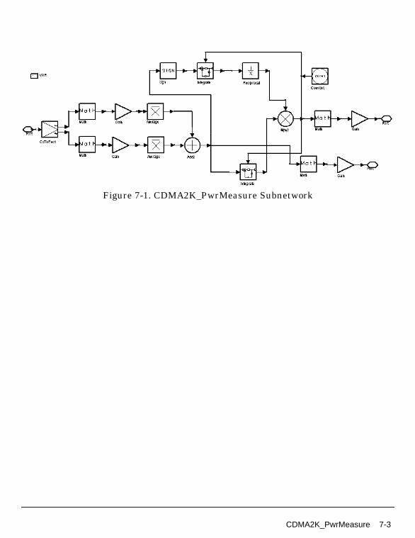
Figure 7-1. CDMA2K_PwrMeasure Subnetwork
CDMA2K_PwrMeasure 7-3
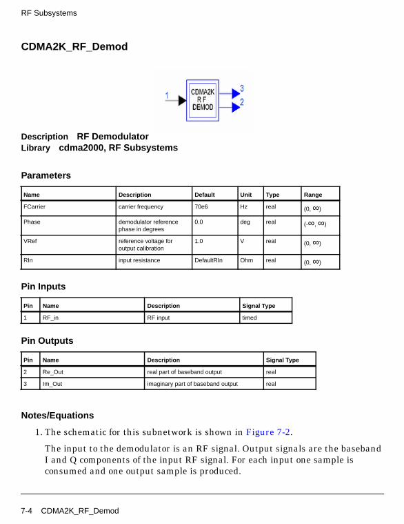
RF Subsystems
CDMA2K_RF_Demod
Description RF DemodulatorLibrary cdma2000, RF Subsystems
Parameters
Pin Inputs
Pin Outputs
Notes/Equations
1. The schematic for this subnetwork is shown in Figure 7-2.
The input to the demodulator is an RF signal. Output signals are the basebandI and Q components of the input RF signal. For each input one sample isconsumed and one output sample is produced.
Name Description Default Unit Type Range
FCarrier carrier frequency 70e6 Hz real (0, ∞)
Phase demodulator referencephase in degrees
0.0 deg real (-∞, ∞)
VRef reference voltage foroutput calibration
1.0 V real (0, ∞)
RIn input resistance DefaultRIn Ohm real (0, ∞)
Pin Name Description Signal Type
1 RF_in RF input timed
Pin Name Description Signal Type
2 Re_Out real part of baseband output real
3 Im_Out imaginary part of baseband output real
7-4 CDMA2K_RF_Demod
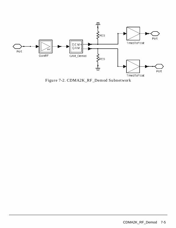
Figure 7-2. CDMA2K_RF_Demod Subnetwork
CDMA2K_RF_Demod 7-5
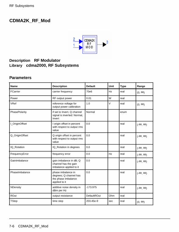
RF Subsystems
CDMA2K_RF_Mod
Description RF ModulatorLibrary cdma2000, RF Subsystems
Parameters
Name Description Default Unit Type Range
FCarrier carrier frequency 70e6 Hz real (0, ∞)
Power RF output power 0.01 W real
VRef reference voltage foroutput power calibration
1.0 V real (0, ∞)
PhasePolarity if set to Invert, Q channelsignal is inverted: Normal,Invert
Normal enum
I_OriginOffset I origin offset in percentwith respect to output rmsvalue
0.0 real (-∞, ∞)
Q_OriginOffset Q origin offset in percentwith respect to output rmsvalue
0.0 real (-∞, ∞)
IQ_Rotation IQ_Rotation in degrees 0.0 real (-∞, ∞)
FrequencyError frequency error 0.0 Hz real (-∞, ∞)
GainImbalance gain imbalance in dB; Qchannel has the gainimbalance applied to it
0.0 real (-∞, ∞)
PhaseImbalance phase imbalance indegrees; Q channel hasthe phase imbalanceapplied to it
0.0 real (-∞, ∞)
NDensity additive noise density indBm per Hz
-173.975 real (-∞, ∞)
ROut output resistance DefaultROut Ohm real
TStep time step 203.45e-9 sec real (0, ∞)
7-6 CDMA2K_RF_Mod
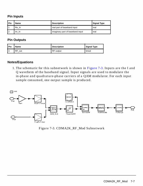
Pin Inputs
Pin Outputs
Notes/Equations
1. The schematic for this subnetwork is shown in Figure 7-3. Inputs are the I andQ waveform of the baseband signal. Input signals are used to modulate thein-phase and quadrature-phase carriers of a QAM modulator. For each inputsample consumed, one output sample is produced.
Figure 7-3. CDMA2K_RF_Mod Subnetwork
Pin Name Description Signal Type
1 Re_In real part of baseband input real
2 Im_In imaginary part of baseband input real
Pin Name Description Signal Type
3 RF_out RF output timed
CDMA2K_RF_Mod 7-7

RF Subsystems
7-8

Chapter 8: Signal Sources
8-1
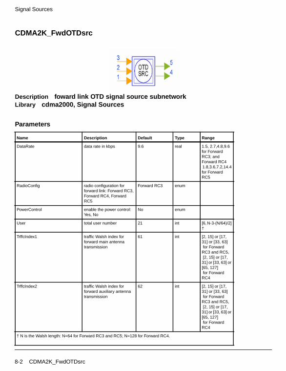
Signal Sources
CDMA2K_FwdOTDsrc
Description foward link OTD signal source subnetworkLibrary cdma2000, Signal Sources
Parameters
Name Description Default Type Range
DataRate data rate in kbps 9.6 real 1.5, 2.7,4.8,9.6for ForwardRC3; andForward RC41.8,3.6,7.2,14.4for ForwardRC5
RadioConfig radio configuration forforward link: Forward RC3,Forward RC4, ForwardRC5
Forward RC3 enum
PowerControl enable the power control:Yes, No
No enum
User total user number 21 int [6, N-3-(N/64)/2]†
TrffcIndex1 traffic Walsh index forforward main antennatransmission
61 int [2, 15] or [17,31] or [33, 63] for ForwardRC3 and RC5, [2, 15] or [17,31] or [33, 63] or[65, 127] for ForwardRC4
TrffcIndex2 traffic Walsh index forforward auxiliary antennatransmission
62 int [2, 15] or [17,31] or [33, 63] for ForwardRC3 and RC5, [2, 15] or [17,31] or [33, 63] or[65, 127] for ForwardRC4
† N is the Walsh length: N=64 for Forward RC3 and RC5; N=128 for Forward RC4.
8-2 CDMA2K_FwdOTDsrc

Pin Inputs
Pin Outputs
Notes/Equations
1. This subnetwork provides forward link OTD signal source for different radioconfigurations and data rates. The schematic is shown in Figure 8-1.
Figure 8-1. CDMA2K_FwdOTDsrc Subnetwork
References
[1]3GPP2 C.S0002_A_1, “Physical Layer Standard for cdma2000 Spread SpectrumSystems Release A-Addendum 1,” Oct. 27, 2000
Pin Name Description Signal Type
1 In input data int
2 PC_in power control bits added into the radio frame tocontrol the reverse transmission power
int
3 PC power control bits for forward link transmission int
Pin Name Description Signal Type
4 Out1 output data for forward main antenna transmission complex
5 Out2 output data for forward auxiliary antennatransmission
complex
CDMA2K_FwdOTDsrc 8-3

Signal Sources
CDMA2K_FwdPilotSrc
Description foward link pilot signal source subnetworkLibrary cdma2000, Signal Sources
Parameters
Pin Outputs
Notes/Equations
1. This subnetwork produces the forward pilot signal. The schematic is shown inFigure 8-2.
Figure 8-2. CDMA2K_FwdPilotSrc Subnetwork
References
[1]3GPP2 C.S0002_A_1, “Physical Layer Standard for cdma2000 Spread SpectrumSystems Release A-Addendum 1,” Oct. 27, 2000
Name Description Default Type
PilotGain pilot gain 2.6 real
Pin Name Description Signal Type
1 Out output data complex
8-4 CDMA2K_FwdPilotSrc
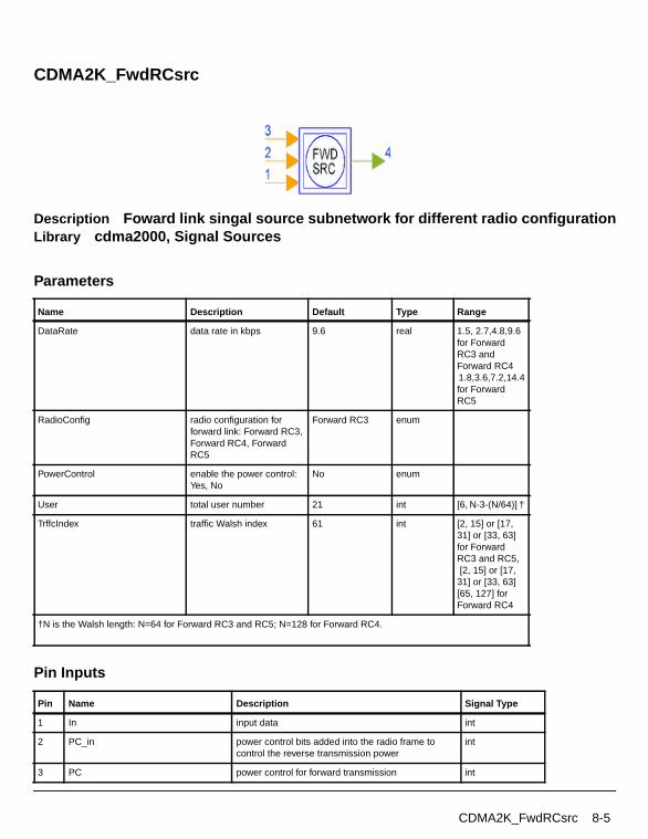
CDMA2K_FwdRCsrc
Description Foward link singal source subnetwork for different radio configurationLibrary cdma2000, Signal Sources
Parameters
Pin Inputs
Name Description Default Type Range
DataRate data rate in kbps 9.6 real 1.5, 2.7,4.8,9.6for ForwardRC3 andForward RC41.8,3.6,7.2,14.4for ForwardRC5
RadioConfig radio configuration forforward link: Forward RC3,Forward RC4, ForwardRC5
Forward RC3 enum
PowerControl enable the power control:Yes, No
No enum
User total user number 21 int [6, N-3-(N/64)] †
TrffcIndex traffic Walsh index 61 int [2, 15] or [17,31] or [33, 63]for ForwardRC3 and RC5, [2, 15] or [17,31] or [33, 63][65, 127] forForward RC4
†N is the Walsh length: N=64 for Forward RC3 and RC5; N=128 for Forward RC4.
Pin Name Description Signal Type
1 In input data int
2 PC_in power control bits added into the radio frame tocontrol the reverse transmission power
int
3 PC power control for forward transmission int
CDMA2K_FwdRCsrc 8-5
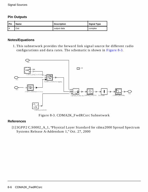
Signal Sources
Pin Outputs
Notes/Equations
1. This subnetwork provides the forward link signal source for different radioconfigurations and data rates. The schematic is shown in Figure 8-3.
Figure 8-3. CDMA2K_FwdRCsrc Subnetwork
References
[1]3GPP2 C.S0002_A_1, “Physical Layer Standard for cdma2000 Spread SpectrumSystems Release A-Addendum 1,” Oct. 27, 2000
Pin Name Description Signal Type
4 Out output data complex
8-6 CDMA2K_FwdRCsrc
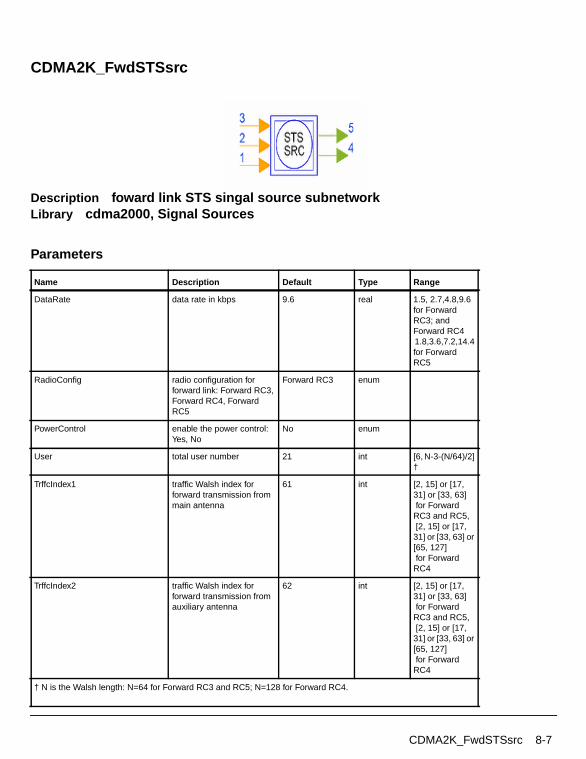
CDMA2K_FwdSTSsrc
Description foward link STS singal source subnetworkLibrary cdma2000, Signal Sources
Parameters
Name Description Default Type Range
DataRate data rate in kbps 9.6 real 1.5, 2.7,4.8,9.6for ForwardRC3; andForward RC41.8,3.6,7.2,14.4for ForwardRC5
RadioConfig radio configuration forforward link: Forward RC3,Forward RC4, ForwardRC5
Forward RC3 enum
PowerControl enable the power control:Yes, No
No enum
User total user number 21 int [6, N-3-(N/64)/2]†
TrffcIndex1 traffic Walsh index forforward transmission frommain antenna
61 int [2, 15] or [17,31] or [33, 63] for ForwardRC3 and RC5, [2, 15] or [17,31] or [33, 63] or[65, 127] for ForwardRC4
TrffcIndex2 traffic Walsh index forforward transmission fromauxiliary antenna
62 int [2, 15] or [17,31] or [33, 63] for ForwardRC3 and RC5, [2, 15] or [17,31] or [33, 63] or[65, 127] for ForwardRC4
† N is the Walsh length: N=64 for Forward RC3 and RC5; N=128 for Forward RC4.
CDMA2K_FwdSTSsrc 8-7
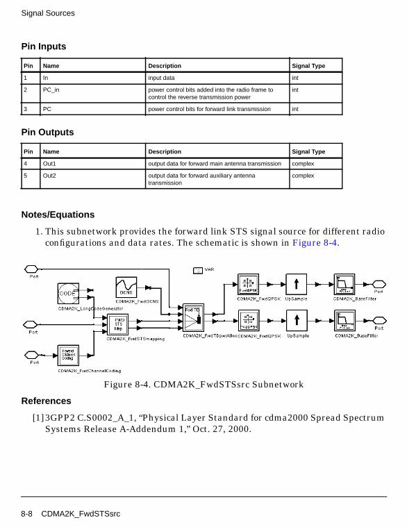
Signal Sources
Pin Inputs
Pin Outputs
Notes/Equations
1. This subnetwork provides the forward link STS signal source for different radioconfigurations and data rates. The schematic is shown in Figure 8-4.
Figure 8-4. CDMA2K_FwdSTSsrc Subnetwork
References
[1]3GPP2 C.S0002_A_1, “Physical Layer Standard for cdma2000 Spread SpectrumSystems Release A-Addendum 1,” Oct. 27, 2000.
Pin Name Description Signal Type
1 In input data int
2 PC_in power control bits added into the radio frame tocontrol the reverse transmission power
int
3 PC power control bits for forward link transmission int
Pin Name Description Signal Type
4 Out1 output data for forward main antenna transmission complex
5 Out2 output data for forward auxiliary antennatransmission
complex
8-8 CDMA2K_FwdSTSsrc
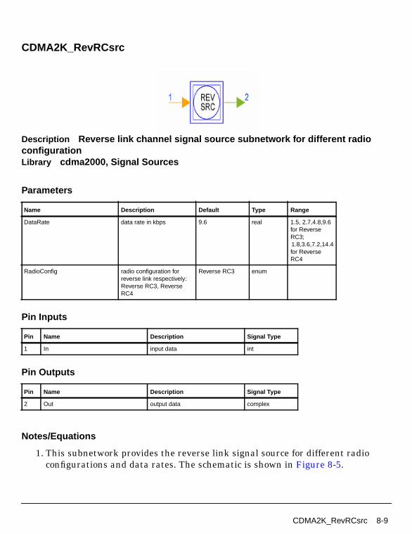
CDMA2K_RevRCsrc
Description Reverse link channel signal source subnetwork for different radioconfigurationLibrary cdma2000, Signal Sources
Parameters
Pin Inputs
Pin Outputs
Notes/Equations
1. This subnetwork provides the reverse link signal source for different radioconfigurations and data rates. The schematic is shown in Figure 8-5.
Name Description Default Type Range
DataRate data rate in kbps 9.6 real 1.5, 2.7,4.8,9.6for ReverseRC3;1.8,3.6,7.2,14.4for ReverseRC4
RadioConfig radio configuration forreverse link respectively:Reverse RC3, ReverseRC4
Reverse RC3 enum
Pin Name Description Signal Type
1 In input data int
Pin Name Description Signal Type
2 Out output data complex
CDMA2K_RevRCsrc 8-9

Signal Sources
Figure 8-5. CDMA2K_RevRCsrc Subnetwork
References
[1]3GPP2 C.S0002_A_1, “Physical Layer Standard for cdma2000 Spread SpectrumSystems Release A-Addendum 1,” Oct. 27, 2000.
8-10 CDMA2K_RevRCsrc
Chapter 9: BER and FER Design Examples
IntroductionThe CDMA2K_BER_prj project shows design examples for measuring forward andreverse link BER and FER, including AWGN. The following sections describe thedesigns and provide schematics and simulation results.
Forward Link Radio Configuration 3 BER and FER• DsnCDMA2K_FwdRC3AWGN.dsn
Features
• Forward pilot channel and one fundamental channel
• FER and BER vs. Eb/N0 of fundamental channel performance curves
Description
This example shows performance of a forward link of RC3 with 9600bps data rate,and 20ms frame under AWGN condition. One pilot channel and one fundamentalchannel are included. It is assumed that the pilot channel occupies 20% of total powerand the fundamental channel occupies 3% of total power.
Schematics
The schematic for DsnCDMA2K_FwdRC3AWGN.dsn is shown in Figure 9-1.
Introduction 9-1
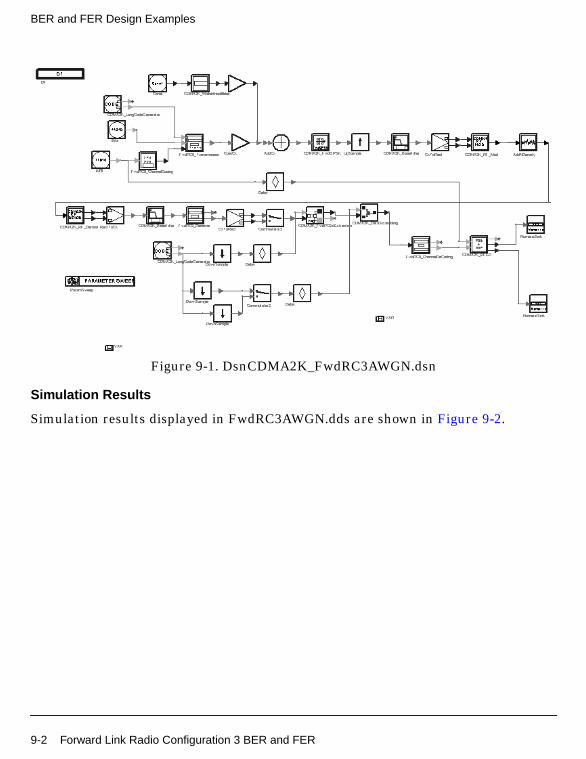
BER and FER Design Examples
Figure 9-1. DsnCDMA2K_FwdRC3AWGN.dsn
Simulation Results
Simulation results displayed in FwdRC3AWGN.dds are shown in Figure 9-2.
9-2 Forward Link Radio Configuration 3 BER and FER
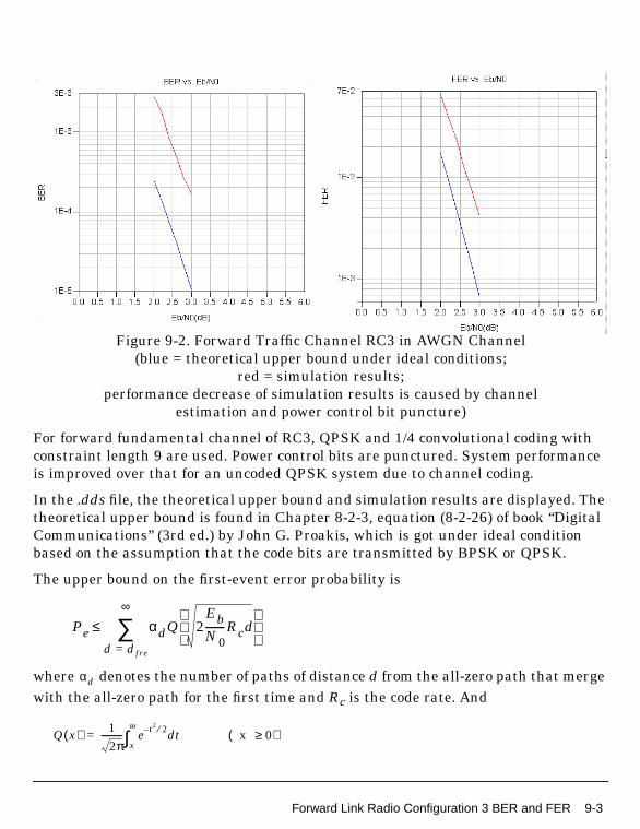
Figure 9-2. Forward Traffic Channel RC3 in AWGN Channel(blue = theoretical upper bound under ideal conditions;
red = simulation results;performance decrease of simulation results is caused by channel
estimation and power control bit puncture)
For forward fundamental channel of RC3, QPSK and 1/4 convolutional coding withconstraint length 9 are used. Power control bits are punctured. System performanceis improved over that for an uncoded QPSK system due to channel coding.
In the .dds file, the theoretical upper bound and simulation results are displayed. Thetheoretical upper bound is found in Chapter 8-2-3, equation (8-2-26) of book “DigitalCommunications” (3rd ed.) by John G. Proakis, which is got under ideal conditionbased on the assumption that the code bits are transmitted by BPSK or QPSK.
The upper bound on the first-event error probability is
where denotes the number of paths of distance d from the all-zero path that mergewith the all-zero path for the first time and Rc is the code rate. And
Pe αdQ 2EbN0--------Rcd
d dfre=
∞
∑≤
αd
Q x( ) 1
2π---------- e t2 2⁄– t x 0≥( )d
x
∞∫=
Forward Link Radio Configuration 3 BER and FER 9-3
BER and FER Design Examples
For a frame of length l, the frame error probability PF is upper bounded by Pe, i.e.,
In general, the transfer function for the code can be expressed as
where f(d) denotes the exponent of N as a function of d. Taking the derivative ofT(D,N) with respect to N and setting N=1, we obtain . Thus, the bit errorprobability is upper-bounded by
dfree of this 1/4 rate convolutional code is 24.
At 1% FER, this upper bound is very tight, and the simulation result isapproximately 0.5dB worse than the theoretical threshold; this is because:
• Channel estimation through forward pilot channel is performed in the receiver,which cannot be perfect, especially under low SNR.
• Power control bits are punctured in the traffic channel, which causes energyloss and coding gain decrease. On the traffic channel, 11/12 power is used totransmit traffic bits and 1/12 is used to transmit power control bits, whichcauses a 0.38dB energy loss. And, the coding gain will be less than pure 1/4convolutional coding.
Simulation results show that at 1e-3 BER, the coded channel provides the sameperformance at 4.5dB lower Eb/N0 than does the channel with no coding (QPSKperformance), that is, the coding gain is approximately 4.5dB.
Benchmark
• Hardware platform: Pentium III 800 MHz, 512 MB memory
• Software platform: Windows NT 2000, ADS 1.5
• Data points: 6 Eb/N0 values
• Simulation time: approximately 47.8 hours
PF 1 1 Pe–( )l–≤
T D N,( ) αdDdN f d( )
D eEbN0-------- Rc–
=d dfree=
∞
∑=
βd αd f d( )=
Pb βdQ 2Eb
N0-------Rcd
d dfre=
∞
∑≤
9-4 Forward Link Radio Configuration 3 BER and FER
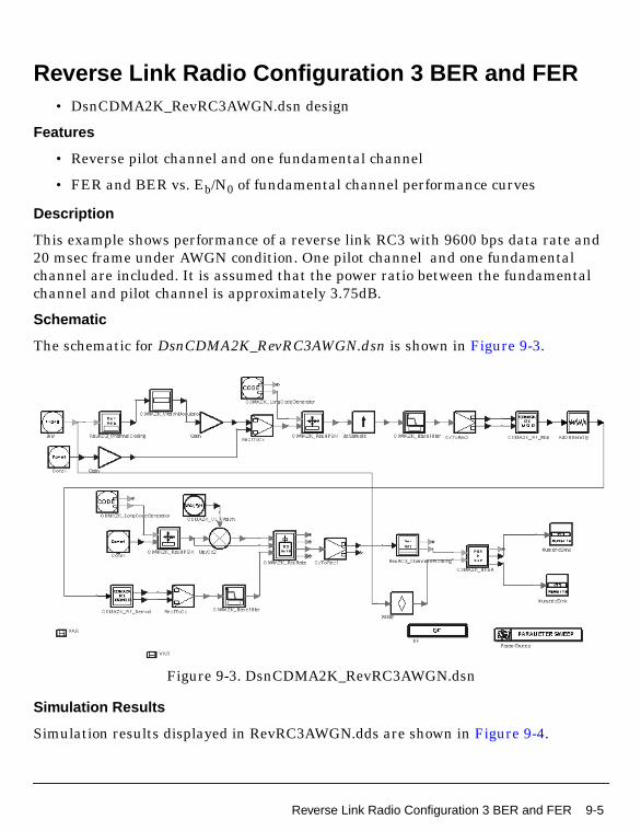
Reverse Link Radio Configuration 3 BER and FER• DsnCDMA2K_RevRC3AWGN.dsn design
Features
• Reverse pilot channel and one fundamental channel
• FER and BER vs. Eb/N0 of fundamental channel performance curves
Description
This example shows performance of a reverse link RC3 with 9600 bps data rate and20 msec frame under AWGN condition. One pilot channel and one fundamentalchannel are included. It is assumed that the power ratio between the fundamentalchannel and pilot channel is approximately 3.75dB.
Schematic
The schematic for DsnCDMA2K_RevRC3AWGN.dsn is shown in Figure 9-3.
Figure 9-3. DsnCDMA2K_RevRC3AWGN.dsn
Simulation Results
Simulation results displayed in RevRC3AWGN.dds are shown in Figure 9-4.
Reverse Link Radio Configuration 3 BER and FER 9-5
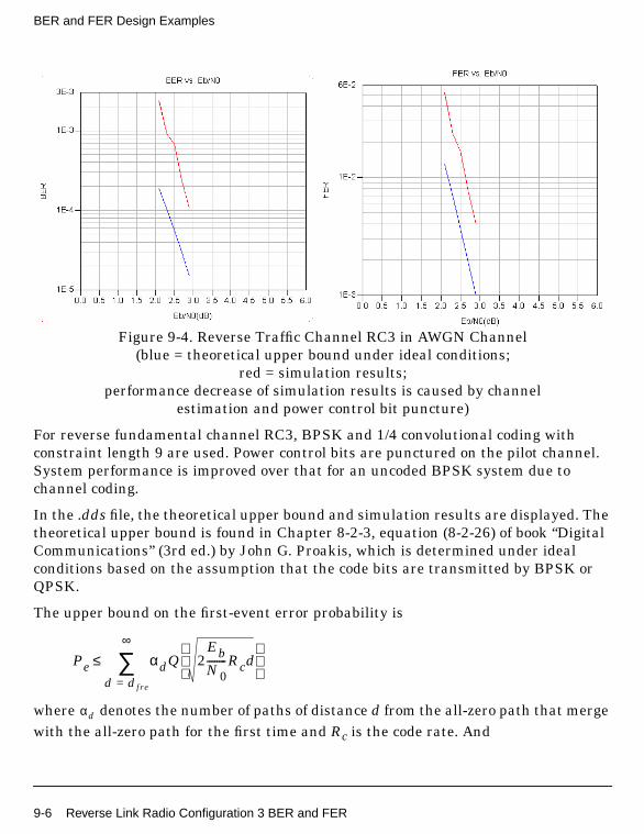
BER and FER Design Examples
Figure 9-4. Reverse Traffic Channel RC3 in AWGN Channel(blue = theoretical upper bound under ideal conditions;
red = simulation results;performance decrease of simulation results is caused by channel
estimation and power control bit puncture)
For reverse fundamental channel RC3, BPSK and 1/4 convolutional coding withconstraint length 9 are used. Power control bits are punctured on the pilot channel.System performance is improved over that for an uncoded BPSK system due tochannel coding.
In the .dds file, the theoretical upper bound and simulation results are displayed. Thetheoretical upper bound is found in Chapter 8-2-3, equation (8-2-26) of book “DigitalCommunications” (3rd ed.) by John G. Proakis, which is determined under idealconditions based on the assumption that the code bits are transmitted by BPSK orQPSK.
The upper bound on the first-event error probability is
where denotes the number of paths of distance d from the all-zero path that mergewith the all-zero path for the first time and Rc is the code rate. And
Pe αdQ 2EbN0--------Rcd
d dfre=
∞
∑≤
αd
9-6 Reverse Link Radio Configuration 3 BER and FER

For a frame of length l, the frame error probability PF is upper bounded by Pe, i.e.,
In general, the transfer function for the code can be expressed as
where f(d) denotes the exponent of N as a function of d. Taking the derivative ofT(D,N) with respect to N and setting N=1, we obtain . Thus, the bit errorprobability is upper-bounded by
dfree of this 1/4 rate convolutional code is 24.
At 1% FER, this upper bound is very tight, and the simulation result isapproximately 0.45dB worse than the theoretical threshold; this is because:
• Channel estimation through reverse pilot channel is performed in the coherentreceiver and the power of reverse pilot channel is relatively low, which cannotbe perfect, especially under low SNR.
• Power control bits are punctured in the reverse pilot channel, sodecision-feedback is used during this period for channel estimation. The errordecision of power control bits will cause error channel estimation, which issensitive for coherent receiver.
Simulation results show that at 1e-3 BER, the coded channel provides the sameperformance at 4.5dB lower Eb/N0 than does the channel with no coding (BPSKperformance), that is, the coding gain is approximately 4.5dB.
Benchmark
• Hardware platform: Pentium III 800 MHz, 512 MB memory
• Software platform: Windows NT2000 , ADS 1.5
• Data points: 5 Eb/N0 values
• Simulation time: approximately 33.5 hours
Q x( ) 1
2π---------- e t2 2⁄– t x 0≥( )d
x
∞∫=
PF 1 1 Pe–( )l–≤
T D N,( ) αdDdN f d( )
D eEbN0-------- Rc–
=d dfree=
∞
∑=
βd αd f d( )=
Pb βdQ 2Eb
N0-------Rcd
d dfre=
∞
∑≤
Reverse Link Radio Configuration 3 BER and FER 9-7
BER and FER Design Examples
9-8 Reverse Link Radio Configuration 3 BER and FER
Chapter 10: Base Station Receiver DesignExamples
IntroductionThe BS_RX_prj project shows cdma2000 base station receiver characteristics,including receiver sensitivity and dynamic range, single-tone desensitization withand without transmitter leakage, intermodulation spurious response attenuation,adjacent channel selectivity, and reverse traffic channel demodulation performance.Designs for these measurements include:
• BS_RxAdjacentSelectivityRC3.dsn for base station receiver adjacent channelselectivity
• BS_RxDemodRC4AWGN.dsn for reverse traffic channel demodulationperformance
• BS_RxDnmcRngRC3.dsn for base station receiver sensitivity and dynamicrange
• BS_RxIntermodulationRC3.dsn for base station receiver intermodulationspurious response attenuation
• BS_RxSingleToneRC3.dsn for base station receiver single-tone desensitization
• BS_RxTxLeakageRC3 for base station receiver single-tone desensitization withtransmitter leakage
Designs under this project consist of:
• MS signal source in baseband
CDMA2K_RevRCsrc provides the uplink signal source of different radioconfigurations and data rates.
• Transmit modulation and up-convertor
The data source of base band output from CDMA2K_RevRCsrc is up-convertedto IF signal with CDMA2K_RF_Mod, then modulated into RF signal withRF_TX_IFin.
• Channel loss and interfering signal combination
Introduction 10-1
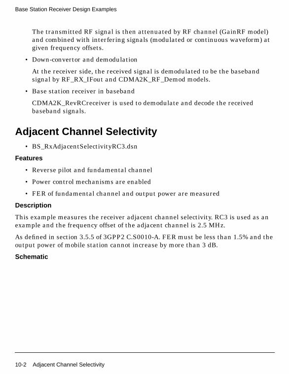
Base Station Receiver Design Examples
The transmitted RF signal is then attenuated by RF channel (GainRF model)and combined with interfering signals (modulated or continuous waveform) atgiven frequency offsets.
• Down-convertor and demodulation
At the receiver side, the received signal is demodulated to be the basebandsignal by RF_RX_IFout and CDMA2K_RF_Demod models.
• Base station receiver in baseband
CDMA2K_RevRCreceiver is used to demodulate and decode the receivedbaseband signals.
Adjacent Channel Selectivity• BS_RxAdjacentSelectivityRC3.dsn
Features
• Reverse pilot and fundamental channel
• Power control mechanisms are enabled
• FER of fundamental channel and output power are measured
Description
This example measures the receiver adjacent channel selectivity. RC3 is used as anexample and the frequency offset of the adjacent channel is 2.5 MHz.
As defined in section 3.5.5 of 3GPP2 C.S0010-A. FER must be less than 1.5% and theoutput power of mobile station cannot increase by more than 3 dB.
Schematic
10-2 Adjacent Channel Selectivity

Figure 10-1. BS_RxAdjacentSelectivityRC3.dsn Schematic
Notes
Outer loop power control is enabled to adjust the SIR threshold.
Simulation Results
Simulation results displayed in BS_RxAdjacentSelectivityRC3.dds are shown inFigure 10-1.
Adjacent Channel Selectivity 10-3
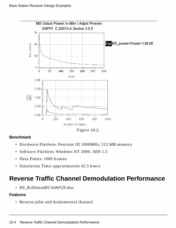
Base Station Receiver Design Examples
Figure 10-2.
Benchmark
• Hardware Platform: Pentium III 1000MHz, 512 MB memory
• Software Platform: Windows NT 2000, ADS 1.5
• Data Points: 1000 frames.
• Simulation Time: approximately 42.5 hours
Reverse Traffic Channel Demodulation Performance• BS_RxDemodRC4AWGN.dsn
Features
• Reverse pilot and fundamental channel
10-4 Reverse Traffic Channel Demodulation Performance
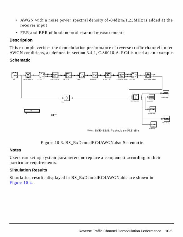
• AWGN with a noise power spectral density of -84dBm/1.23MHz is added at thereceiver input
• FER and BER of fundamental channel measurements
Description
This example verifies the demodulation performance of reverse traffic channel underAWGN conditions, as defined in section 3.4.1, C.S0010-A. RC4 is used as an example.
Schematic
Figure 10-3. BS_RxDemodRC4AWGN.dsn Schematic
Notes
Users can set up system parameters or replace a component according to theirparticular requirements.
Simulation Results
Simulation results displayed in BS_RxDemodRC4AWGN.dds are shown inFigure 10-4.
Reverse Traffic Channel Demodulation Performance 10-5

Base Station Receiver Design Examples
Figure 10-4. Demodulation with AWGN Simulation Results
Benchmark
• Hardware Platform: Pentium III 1000MHz, 512M memory
• Software Platform: Windows 2000, ADS 1.5
• Data Points: 300 frames
• Simulation Time: approximately 10 hours
Receiver Sensitivity and Dynamic RangeBS_RxDnmcRngRC3.dsn
Features
• Reverse pilot and fundamental channel
• Dynamic range determined through parameter sweeping
• FER and BER of fundamental channel measurement
Description
This example measures the receiver sensitivity and dynamic range, as defined insection 3.5.1 and 3.5.2 of 3GPP2 C.S0010-A. FER is maintained at 1%. RC3 is used asan example.
Schematics
10-6 Receiver Sensitivity and Dynamic Range

Figure 10-5. BS_RxDnmcRngRC3.dsn Schematic
Notes
The dynamic range can be measured through changing the signal power at receiverside.
Simulation Results
Simulation results displayed in BS_RxDnmcRngRC3.dds. are shown in Figure 10-6.
Receiver Sensitivity and Dynamic Range 10-7

Base Station Receiver Design Examples
Figure 10-6. BER and FER of Fundamental Channel
Benchmark
• Hardware Platform: Pentium II 400 MHz, 512 MB memory
• Software Platform: Windows NT 4.0 Workstation, ADS 1.5
• Data Points: 100 frames.
• Simulation Time: approximately 4.1 hours
Intermodulation Spurious Response Attenuation• BS_RxIntermodulationRC3.dsn
Features
• Reverse pilot and fundamental channel
• Power control mechanisms are enabled
10-8 Intermodulation Spurious Response Attenuation
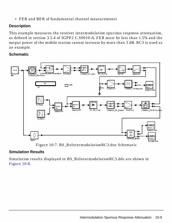
• FER and BER of fundamental channel measurements
Description
This example measures the receiver intermodulation spurious response attenuation,as defined in section 3.5.4 of 3GPP2 C.S0010-A. FER must be less than 1.5% and theoutput power of the mobile station cannot increase by more than 3 dB. RC3 is used asan example.
Schematic
Figure 10-7. BS_RxIntermodulationRC3.dsn Schematic
Simulation Results
Simulation results displayed in BS_RxIntermodulationRC3.dds are shown inFigure 10-8.
Intermodulation Spurious Response Attenuation 10-9
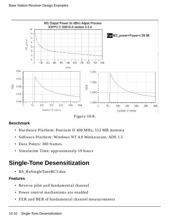
Base Station Receiver Design Examples
Figure 10-8.
Benchmark
• Hardware Platform: Pentium II 400 MHz, 512 MB memory
• Software Platform: Windows NT 4.0 Workstation, ADS 1.5
• Data Points: 300 frames.
• Simulation Time: approximately 19 hours
Single-Tone Desensitization• BS_RxSingleToneRC3.dsn
Features
• Reverse pilot and fundamental channel
• Power control mechanisms are enabled
• FER and BER of fundamental channel measurements
10-10 Single-Tone Desensitization

Description
This example measures the receiver single tone desensitization, as defined in section3.5.3 of 3GPP2 C.S0010-A. FER must be less than 1.5% and the output power of themobile station cannot increase by more than 3 dB. RC3 is used as an example.
Schematic
Figure 10-9. BS_RxSingleToneRC3.dsn Schematic
Simulation Results
Simulation results displayed in BS_RxSingleToneRC3.dds are shown inFigure 10-10.
Single-Tone Desensitization 10-11

Base Station Receiver Design Examples
Figure 10-10.
Benchmark
• Hardware Platform: Pentium III 1000 MHz, 512 MB memory
• Software Platform: Windows 2000, ADS 1.5
• Data Points: 300 frames
• Simulation Time: approximately 8.8 hours
Single-Tone Desensitization with Transmit Leakage• BS_RxTxLeakageRC3.dsn
Features
• Reverse pilot and fundamental channel
• Power control mechanisms are enabled
10-12 Single-Tone Desensitization with Transmit Leakage

• Forward pilot is used as the transmit leakage and is transmitted at maximumpower (approximately 43dBm in this setup).
• Isolation of duplexer is 100dBm
• FER and BER of fundamental channel
Description
This example measures the receiver single-tone desensitization, with transmitterleakage. RC3 is used as an example.
Schematic
Figure 10-11. BS_RxTxLeakageRC3.dsn Schematic
Single-Tone Desensitization with Transmit Leakage 10-13
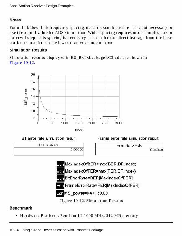
Base Station Receiver Design Examples
Notes
For uplink/downlink frequency spacing, use a reasonable value—it is not necessary touse the actual value for ADS simulation. Wider spacing requires more samples due tonarrow Tstep. This spacing is necessary in order for the direct leakage from the basestation transmitter to be lower than cross modulation.
Simulation Results
Simulation results displayed in BS_RxTxLeakageRC3.dds are shown inFigure 10-12.
Figure 10-12. Simulation Results
Benchmark
• Hardware Platform: Pentium III 1000 MHz, 512 MB memory
10-14 Single-Tone Desensitization with Transmit Leakage
• Software Platform: Windows 2000, ADS 1.5
• Data Points: 300 frames.
• Simulation Time: approximately 19.8 hours
Single-Tone Desensitization with Transmit Leakage 10-15
Base Station Receiver Design Examples
10-16 Single-Tone Desensitization with Transmit Leakage

Chapter 11: Base Station Transmitter DesignExamples
IntroductionThe BS_TX_prj project shows cdma2000 base station transmitter characteristics,including waveform quality (rho), mean power, pilot power, code domain power andconducted spurious emissions. Designs for these include:
• BS_TxCDP_RC3 and BS_TxCDP_RC3OTD.dsn measures code domain powerwith and without transmit diversity
• BS_TxMeanPower.dsn measures mean power of RF output
• BS_TxPilotPower.dsn measures pilot channel power to total power ratio
• BS_TxRho.dsn for waveform quality measurement
• BS_TxSR1Spectrum.dsn for conducted spurious emissions measurement
Designs under this project consist of:
• BS signal source in baseband
CDMA2K_FwdRCsrc and CDMA2K_FwdOTDsrc provide the downlink signalsource of different radio configurations and data rates without and withtransmit diversity.
CDMA2K_FwdPilotSrc provides the signal transmitted on the forward pilotchannel.
• Transmit modulation and up-convertor
The data source of base band output from CDMA2K_FwdRCsrc is up-convertedto IF signal with CDMA2K_RF_Mod, then modulated into RF signal withRF_TX_IFin.
• Code domain power measurement
CDMA2K_CDP is used to measure the code domain power.
• Mean power measurement
CDMA2K_PwrMeasure is used to measure the mean power of input signal.
• Rho measurement
Introduction 11-1
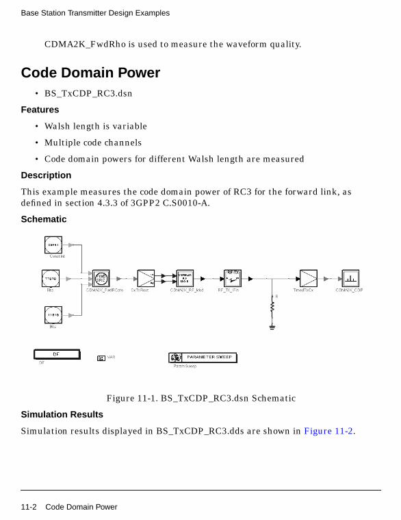
Base Station Transmitter Design Examples
CDMA2K_FwdRho is used to measure the waveform quality.
Code Domain Power• BS_TxCDP_RC3.dsn
Features
• Walsh length is variable
• Multiple code channels
• Code domain powers for different Walsh length are measured
Description
This example measures the code domain power of RC3 for the forward link, asdefined in section 4.3.3 of 3GPP2 C.S0010-A.
Schematic
Figure 11-1. BS_TxCDP_RC3.dsn Schematic
Simulation Results
Simulation results displayed in BS_TxCDP_RC3.dds are shown in Figure 11-2.
11-2 Code Domain Power
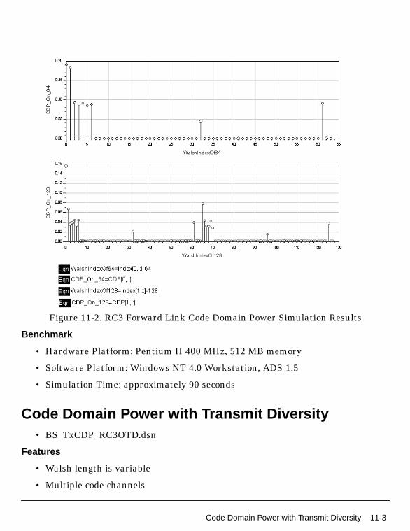
Figure 11-2. RC3 Forward Link Code Domain Power Simulation Results
Benchmark
• Hardware Platform: Pentium II 400 MHz, 512 MB memory
• Software Platform: Windows NT 4.0 Workstation, ADS 1.5
• Simulation Time: approximately 90 seconds
Code Domain Power with Transmit Diversity• BS_TxCDP_RC3OTD.dsn
Features
• Walsh length is variable
• Multiple code channels
Code Domain Power with Transmit Diversity 11-3
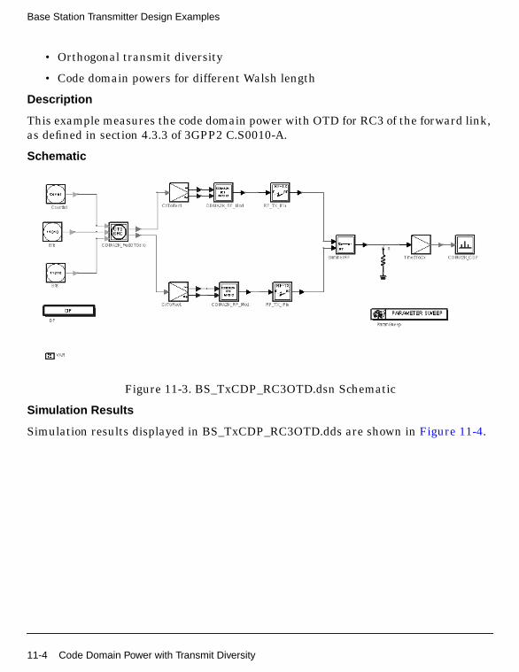
Base Station Transmitter Design Examples
• Orthogonal transmit diversity
• Code domain powers for different Walsh length
Description
This example measures the code domain power with OTD for RC3 of the forward link,as defined in section 4.3.3 of 3GPP2 C.S0010-A.
Schematic
Figure 11-3. BS_TxCDP_RC3OTD.dsn Schematic
Simulation Results
Simulation results displayed in BS_TxCDP_RC3OTD.dds are shown in Figure 11-4.
11-4 Code Domain Power with Transmit Diversity

Figure 11-4. RC3 Forward Link Code DomainPower with Transmit Diversity Simulation Results
Benchmark
• Hardware Platform: Pentium II 400 MHz, 512 MB memory
• Software Platform: Windows NT 4.0 Workstation, ADS 1.5
• Simulation Time: approximately 100 seconds
Pilot Channel Power to Total Power Ratio• BS_TxPilotPower.dsn
Features
• Pilot, sync, paging and 6 traffic channels
Pilot Channel Power to Total Power Ratio 11-5
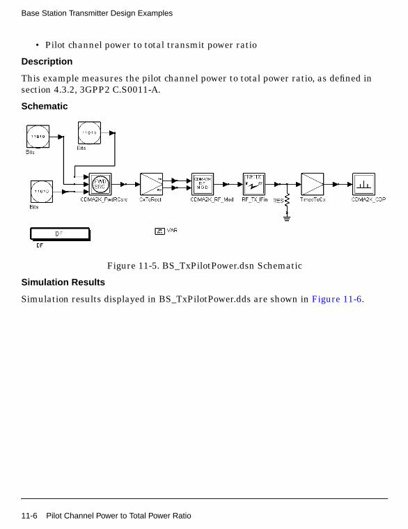
Base Station Transmitter Design Examples
• Pilot channel power to total transmit power ratio
Description
This example measures the pilot channel power to total power ratio, as defined insection 4.3.2, 3GPP2 C.S0011-A.
Schematic
Figure 11-5. BS_TxPilotPower.dsn Schematic
Simulation Results
Simulation results displayed in BS_TxPilotPower.dds are shown in Figure 11-6.
11-6 Pilot Channel Power to Total Power Ratio

Figure 11-6. Pilot Channel Power toTotal Power Ration Simulation Results
Benchmark
• Hardware Platform: Pentium II 400 MHz, 512 MB memory
• Software Platform: Windows NT 4.0 Workstation, ADS 1.5
• Simulation Time: approximately 4minutes
RF Output Mean Power• BS_TxMeanPower.dsn
Features
• Pilot, sync, paging and 6 traffic channels
• Total transmit power measurement
Description
This example measures the mean power of the base station RF output as defined insection 4.3, 3GPP2 C.S0011-A.
RF Output Mean Power 11-7
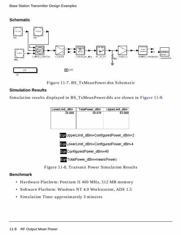
Base Station Transmitter Design Examples
Schematic
Figure 11-7. BS_TxMeanPower.dsn Schematic
Simulation Results
Simulation results displayed in BS_TxMeanPower.dds are shown in Figure 11-8.
Figure 11-8. Transmit Power Simulation Results
Benchmark
• Hardware Platform: Pentium II 400 MHz, 512 MB memory
• Software Platform: Windows NT 4.0 Workstation, ADS 1.5
• Simulation Time: approximately 3 minutes
11-8 RF Output Mean Power

Waveform Quality• BS_TxRho.dsn
Features
• Forward pilot channel is transmitted
• Normalized correlated power, rho, measurement
Description
This example measures the normalized correlated power, rho, for the forward link.Only the forward pilot channel is transmitted, as defined in section 4.2.2 of 3GPP2C.S0010-A.
Schematic
Figure 11-9. BS_TxRho.dsn Schematic
Simulation Results
Simulation results displayed in BS_TxRho.dds are shown in Figure 11-10.
Figure 11-10. Waveform Quality Simulation Results
Benchmark
• Hardware Platform: Pentium II 400 MHz, 512 MB memory
Waveform Quality 11-9
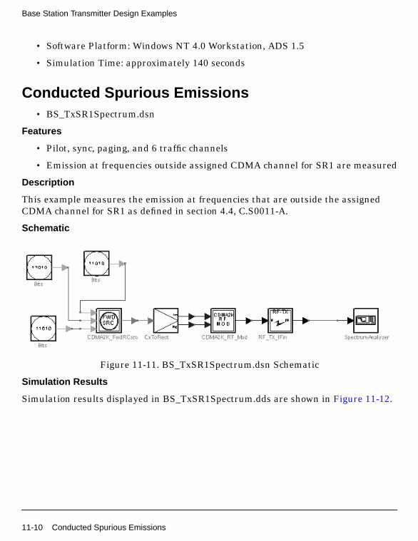
Base Station Transmitter Design Examples
• Software Platform: Windows NT 4.0 Workstation, ADS 1.5
• Simulation Time: approximately 140 seconds
Conducted Spurious Emissions• BS_TxSR1Spectrum.dsn
Features
• Pilot, sync, paging, and 6 traffic channels
• Emission at frequencies outside assigned CDMA channel for SR1 are measured
Description
This example measures the emission at frequencies that are outside the assignedCDMA channel for SR1 as defined in section 4.4, C.S0011-A.
Schematic
Figure 11-11. BS_TxSR1Spectrum.dsn Schematic
Simulation Results
Simulation results displayed in BS_TxSR1Spectrum.dds are shown in Figure 11-12.
11-10 Conducted Spurious Emissions

Figure 11-12. Spurious Emissions Simulation Results
Benchmark
• Hardware Platform: Pentium II 400 MHz, 512 MB memory
• Software Platform: Windows NT 4.0 Workstation, ADS 1.5
• Simulation Time: approximately 4 minutes
Conducted Spurious Emissions 11-11

Base Station Transmitter Design Examples
11-12 Conducted Spurious Emissions

Chapter 12: Measurement Design Examples
IntroductionThe CDMA2K_Measurement_prj project shows examples for measuring forward andreverse link transmission as well as peak to average power performance of HPSK andQPSK. The following sections describe the designs and provide schematics andsimulation results.
Forward Link SR1 Transmission Measurements• DsnCDMA2K_FwdSR1Trans.dsn
Features
• Forward QPSK modulation
• Walsh modulator and Walsh rotation
• De-QPSK structure
• Demodulation and derotation
• 48-order baseband filter
• 1.2288 Mcps chip rate
• Non-linear RF amplifier
• Eye diagram and constellation display during simulation
• EVM and ACPR measurements
Description
DsnCDMA2K_FwdSR1Trans.dsn is an example design for measuring forward linkSR1 transmissions. QPSK, Walsh modulator, Walsh rotator, baseband filter andnon-linear RF amplifier are applied.
After De-QPSK, demodulation and derotation, the I way Eye diagram and receivedsignal constellation are shown in real time.When the amplitude of white noise isadjusted, the eye diagram opening and constellation scattering changes can beviewed.
Schematic
Introduction 12-1
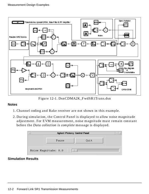
Measurement Design Examples
Figure 12-1. DsnCDMA2K_FwdSR1Trans.dsn
Notes
1. Channel coding and Rake receiver are not shown in this example.
2. During simulation, the Control Panel is displayed to allow noise magnitudeadjustment. For EVM measurement, noise magnitude must remain constantbefore the Data collection is complete message is displayed.
Simulation Results
12-2 Forward Link SR1 Transmission Measurements
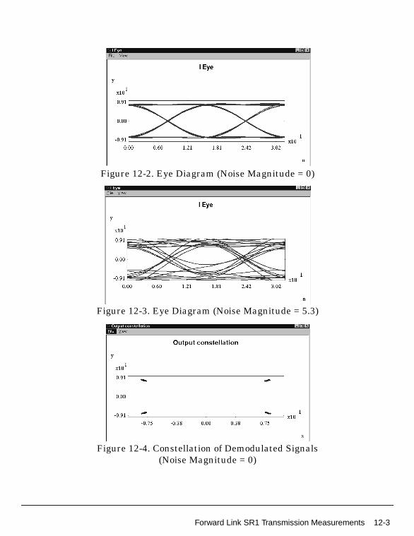
Figure 12-2. Eye Diagram (Noise Magnitude = 0)
Figure 12-3. Eye Diagram (Noise Magnitude = 5.3)
Figure 12-4. Constellation of Demodulated Signals(Noise Magnitude = 0)
Forward Link SR1 Transmission Measurements 12-3

Measurement Design Examples
Figure 12-5. Constellation of Demodulated Signals(Noise Magnitude = 5.3)
Figure 12-6 shows spectrum, ACPR and EVM values. Noise magnitude equals 0.5.The graph is saved in FwdSR1Trans.dds; corresponding data is saved inFwdSR1Trans.ds.
Table 12-1 shows EVM values based on different noise values.
Figure 12-6. ACPR and EVM Performance
Table 12-1. EVM Values
EVM Noise Magnitude Value
0.017 0
0.030 0.5
12-4 Forward Link SR1 Transmission Measurements
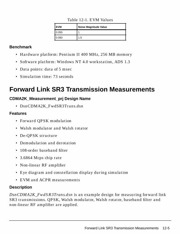
Benchmark
• Hardware platform: Pentium II 400 MHz, 256 MB memory
• Software platform: Windows NT 4.0 workstation, ADS 1.3
• Data points: data of 5 msec
• Simulation time: 73 seconds
Forward Link SR3 Transmission MeasurementsCDMA2K_Measurement_prj Design Name
• DsnCDMA2K_FwdSR3Trans.dsn
Features
• Forward QPSK modulation
• Walsh modulator and Walsh rotator
• De-QPSK structure
• Demodulation and derotation
• 108-order baseband filter
• 3.6864 Mcps chip rate
• Non-linear RF amplifier
• Eye diagram and constellation display during simulation
• EVM and ACPR measurements
Description
DsnCDMA2K_FwdSR3Trans.dsn is an example design for measuring forward linkSR3 transmissions. QPSK, Walsh modulator, Walsh rotator, baseband filter andnon-linear RF amplifier are applied.
0.055 1
0.083 1.5
Table 12-1. EVM Values
EVM Noise Magnitude Value
Forward Link SR3 Transmission Measurements 12-5

Measurement Design Examples
After De-QPSK, demodulation and derotation, the I way Eye diagram and receivedsignal constellation are shown in real time. When the amplitude of white noise isadjusted, the eye diagram opening and constellation scattering changes can beviewed.
Schematic
The schematic for this design is shown in Figure 12-7.
Figure 12-7. DsnCDMA2K_FwdSR3Trans.dsn
Notes
1. Channel coding and Rake receiver are not shown in this example.
2. During simulation, the Control Panel is displayed to allow noise magnitudeadjustment. For EVM measurement, noise magnitude must remain constantthe Data collection is complete message is displayed.
12-6 Forward Link SR3 Transmission Measurements

Simulation Results
Figure 12-8. Eye Diagram(Noise Magnitude = 0)
Figure 12-9. Eye Diagram(Noise Magnitude = 4.5)
Forward Link SR3 Transmission Measurements 12-7
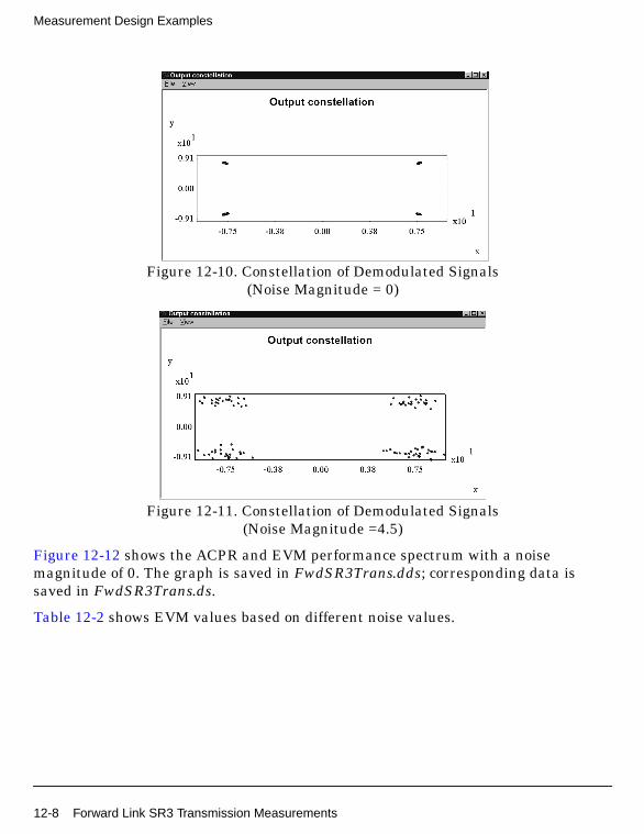
Measurement Design Examples
Figure 12-10. Constellation of Demodulated Signals(Noise Magnitude = 0)
Figure 12-11. Constellation of Demodulated Signals(Noise Magnitude =4.5)
Figure 12-12 shows the ACPR and EVM performance spectrum with a noisemagnitude of 0. The graph is saved in FwdSR3Trans.dds; corresponding data issaved in FwdSR3Trans.ds.
Table 12-2 shows EVM values based on different noise values.
12-8 Forward Link SR3 Transmission Measurements
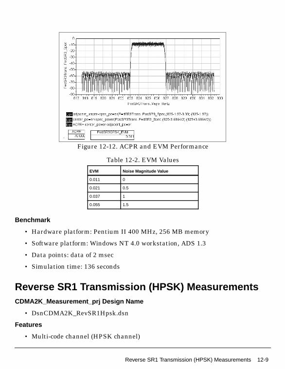
Figure 12-12. ACPR and EVM Performance
Benchmark
• Hardware platform: Pentium II 400 MHz, 256 MB memory
• Software platform: Windows NT 4.0 workstation, ADS 1.3
• Data points: data of 2 msec
• Simulation time: 136 seconds
Reverse SR1 Transmission (HPSK) MeasurementsCDMA2K_Measurement_prj Design Name
• DsnCDMA2K_RevSR1Hpsk.dsn
Features
• Multi-code channel (HPSK channel)
Table 12-2. EVM Values
EVM Noise Magnitude Value
0.011 0
0.021 0.5
0.037 1
0.055 1.5
Reverse SR1 Transmission (HPSK) Measurements 12-9

Measurement Design Examples
• HPSK modulation and demodulation
• 48-order baseband filter
• 1.2288 Mcps chip rate
• Non-linear RF amplifier
• Eye diagram and constellation display during simulation
• EVM, ACPR, and CCDF measurements
Description
DsnCDMA2K_RevSR1Hpsk.dsn is an example design for measuring reverse link SR1transmissions. HPSK, baseband filter, and non-linear RF amplifier are applied.
After HPSK demodulation, the I way Eye diagram and received signal constellationare displayed during simulation. White noise amplitude can be adjusted whileobserving the Eye diagram and constellation scattering.
In this example the Traffic Fundamental Channel signal with Walsh Code Index 5are measured. For this code channel, the modulator method is HPSK. Afterdemodulation, the constellation of this code channel is same as BPSK. So in EVMmeasurement and constellation showing, BPSK mode is referred as standardmodulation type.
Schematics
12-10 Reverse SR1 Transmission (HPSK) Measurements
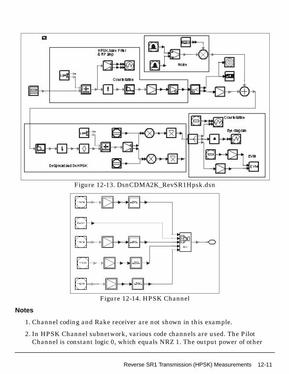
Figure 12-13. DsnCDMA2K_RevSR1Hpsk.dsn
Figure 12-14. HPSK Channel
Notes
1. Channel coding and Rake receiver are not shown in this example.
2. In HPSK Channel subnetwork, various code channels are used. The PilotChannel is constant logic 0, which equals NRZ 1. The output power of other
Reverse SR1 Transmission (HPSK) Measurements 12-11
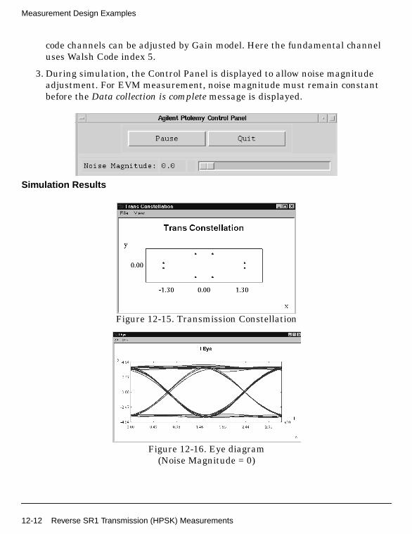
Measurement Design Examples
code channels can be adjusted by Gain model. Here the fundamental channeluses Walsh Code index 5.
3. During simulation, the Control Panel is displayed to allow noise magnitudeadjustment. For EVM measurement, noise magnitude must remain constantbefore the Data collection is complete message is displayed.
Simulation Results
Figure 12-15. Transmission Constellation
Figure 12-16. Eye diagram(Noise Magnitude = 0)
12-12 Reverse SR1 Transmission (HPSK) Measurements

Figure 12-17. Eye Diagram(Noise Magnitude = 1.4)
Figure 12-18. Constellation of Demodulated Signals(Noise Magnitude = 0)
Figure 12-19. Constellation of Demodulated Signals(Noise Magnitude = 1.4)
Reverse SR1 Transmission (HPSK) Measurements 12-13

Measurement Design Examples
Figure 12-20 shows the ACPR and EVM performance spectrum with a noisemagnitude of 0. The graph is saved in RevSR1HPSK.dds; corresponding data is savedin RevSR1HPSK.ds.
Table 12-3 shows EVM values based on different noise values.
Figure 12-21 shows CCDF performance.
Figure 12-20. ACPR and EVM Performance
Table 12-3. EVM Values
EVM Noise Magnitude Value
0.060 0
0.069 0.5
0.103 1
12-14 Reverse SR1 Transmission (HPSK) Measurements

Figure 12-21. CCDF Performance
Benchmark
• Hardware platform: Pentium II 400 MHz, 256 MB memory
• Software platform: Windows NT 4.0 workstation, ADS 1.3
• Data points: data of 5 msec
• Simulation time: 193 seconds
Reverse SR3 Transmission (HPSK) MeasurementsCDMA2K_Measurement_prj Design Name
• DsnCDMA2K_RevSR3Hpsk.dsn
Features
• Multi-code channel (HPSK channel)
• HPSK modulation and demodulation
• 108-order baseband filter
Reverse SR3 Transmission (HPSK) Measurements 12-15
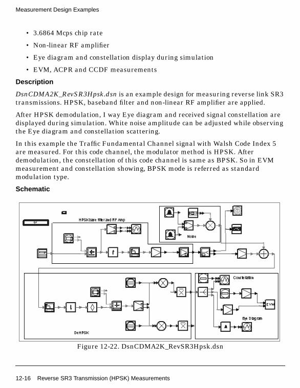
Measurement Design Examples
• 3.6864 Mcps chip rate
• Non-linear RF amplifier
• Eye diagram and constellation display during simulation
• EVM, ACPR and CCDF measurements
Description
DsnCDMA2K_RevSR3Hpsk.dsn is an example design for measuring reverse link SR3transmissions. HPSK, baseband filter and non-linear RF amplifier are applied.
After HPSK demodulation, I way Eye diagram and received signal constellation aredisplayed during simulation. White noise amplitude can be adjusted while observingthe Eye diagram and constellation scattering.
In this example the Traffic Fundamental Channel signal with Walsh Code Index 5are measured. For this code channel, the modulator method is HPSK. Afterdemodulation, the constellation of this code channel is same as BPSK. So in EVMmeasurement and constellation showing, BPSK mode is referred as standardmodulation type.
Schematic
Figure 12-22. DsnCDMA2K_RevSR3Hpsk.dsn
12-16 Reverse SR3 Transmission (HPSK) Measurements

Figure 12-23. HPSK Channel
Notes
1. Channel coding and Rake receiver are not shown in this example.
2. In HPSK Channel subnetwork, various code channels are used. The pilotchannel is constant logic 0, which equals NRZ 1. The output power of the codechannels are allocated according to the frame length, channel coding and its
rate, etc. In this example, Walsh code is used in fundamental channel.
3. During simulation, the Control Panel is displayed to allow noise magnitudeadjustment. For EVM measurement, noise magnitude must remain constantbefore a Data collection is complete message is displayed.
Simulation Results
Figure 12-24 shows the ACPR and EVM performance spectrum. Noise magnitudeequals 0.5. The graph is saved in RevSR3HPSK.dds; corresponding data is saved inRevSR3HPSK.ds.
Table 12-4 shows EVM values based on different noise values.
W165
Reverse SR3 Transmission (HPSK) Measurements 12-17
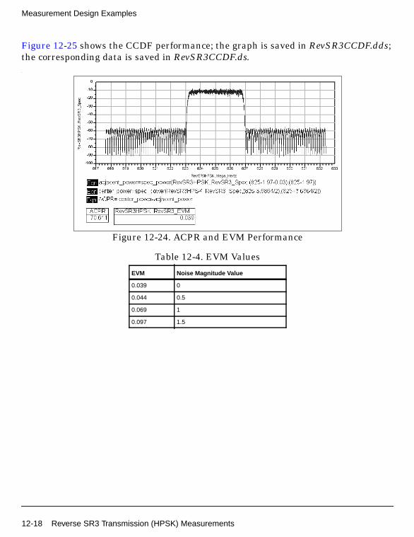
Measurement Design Examples
Figure 12-25 shows the CCDF performance; the graph is saved in RevSR3CCDF.dds;the corresponding data is saved in RevSR3CCDF.ds..
Figure 12-24. ACPR and EVM Performance
Table 12-4. EVM Values
EVM Noise Magnitude Value
0.039 0
0.044 0.5
0.069 1
0.097 1.5
12-18 Reverse SR3 Transmission (HPSK) Measurements
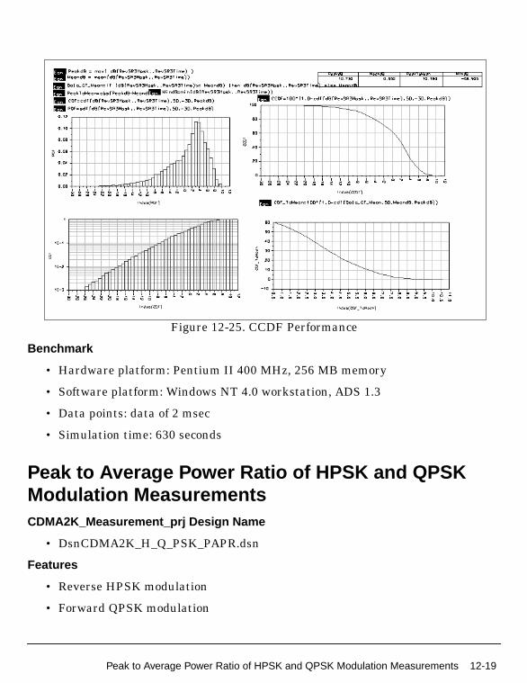
Figure 12-25. CCDF Performance
Benchmark
• Hardware platform: Pentium II 400 MHz, 256 MB memory
• Software platform: Windows NT 4.0 workstation, ADS 1.3
• Data points: data of 2 msec
• Simulation time: 630 seconds
Peak to Average Power Ratio of HPSK and QPSKModulation MeasurementsCDMA2K_Measurement_prj Design Name
• DsnCDMA2K_H_Q_PSK_PAPR.dsn
Features
• Reverse HPSK modulation
• Forward QPSK modulation
Peak to Average Power Ratio of HPSK and QPSK Modulation Measurements 12-19

Measurement Design Examples
• Walsh modulator
• 48-order baseband filter
• Peak to average power ratio (PAPR) measurement
• CCDF measurement
Description
DsnCDMA2K_H_Q_PSK_PAPR.dsn is an example design to compare PAPRperformance of HPSK and QPSK.
Schematic
Figure 12-26. DsnCDMA2K_H_Q_PSK_PAPR.dsn
Notes
1. Channel coding and Rake receiver are not shown in this example.
Simulation Results
Figure 12-27 shows CCDF performance; the graph is saved in H_Q_PSK_PAPR.dds;corresponding data is saved in H_Q_PSK_PAPR.ds. According to the graph, for a
12-20 Peak to Average Power Ratio of HPSK and QPSK Modulation Measurements
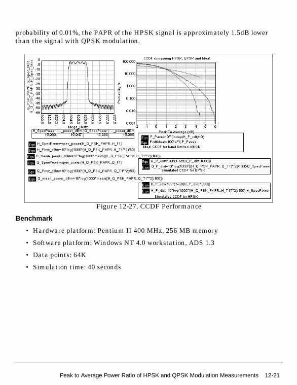
probability of 0.01%, the PAPR of the HPSK signal is approximately 1.5dB lowerthan the signal with QPSK modulation.
Figure 12-27. CCDF Performance
Benchmark
• Hardware platform: Pentium II 400 MHz, 256 MB memory
• Software platform: Windows NT 4.0 workstation, ADS 1.3
• Data points: 64K
• Simulation time: 40 seconds
Peak to Average Power Ratio of HPSK and QPSK Modulation Measurements 12-21
Measurement Design Examples
12-22 Peak to Average Power Ratio of HPSK and QPSK Modulation Measurements

Chapter 13: Mobile Station Receiver DesignExamples
IntroductionThe MS_RX_prj project shows cdma2000 mobile station receiver measurements,including receiver sensitivity and dynamic range, single-tone desensitization withand without TX leakage, intermodulation spurious response attenuation, adjacentchannel selectivity, and reverse traffic channel demodulation performance. Designsfor these measurements include:
• MS_RxAdjacentSelectivityRC3.dsn for mobile station receiver adjacent channelselectivity
• MS_RxDemodRC4AWGN.dsn for forward traffic channel demodulationperformance
• MS_RxDnmcRngRC3.dsn for mobile station receiver sensitivity and dynamicrange
• MS_RxIntermodulationRC3.dsn for mobile station receiver intermodulationspurious response attenuation
• MS_RxSingleToneRC3.dsn for mobile station receiver single-tonedesensitization
• MS_RxTxLeakageRC3 for mobile station receiver single-tone desensitizationwith transmit leakage
Designs under this project consist of:
• BS signal source in baseband
CDMA2K_FwdRCsrc provides the downlink signal source of different radioconfigurations and data rates.
• Transmit modulation and up-convertor
The data source of base band output from CDMA2K_FwdRCsrc is up-convertedto IF signal with CDMA2K_RF_Mod, then modulated into RF signal withRF_TX_IFin.
• Channel loss and interfering signal combination
Introduction 13-1
Mobile Station Receiver Design Examples
The transmitted RF signal is then attenuated by RF channel (GainRF model)and combined with interfering signals (modulated or continuous waveform) atgiven frequency offsets.
• Down-convertor and demodulation
At the receiver side, the received signal is demodulated to be the basebandsignal by RF_RX_IFout and CDMA2K_RF_Demod models.
• Mobile station receiver in baseband
CDMA2K_FwdRCreceiver is used to demodulate and decode the receivedbaseband signals.
Adjacent Channel Selectivity• MS_RxAdjacentSelectivityRC3.dsn
Features
• Forward pilot and fundamental channel
• Ec/Ior is -15.6 dB; Iorr is -101dBm/1.23MHz
• Ec/Ior can be changed by setting User in CDMA2K_FwdRCsrc
• Applies to band class 6 mobile stations only
• FER of fundamental channel measurement
Description
This example measures the receiver adjacent channel selectivity, as defined in section3.5.4 of 3GPP2 C.S0011-A. FER is measured in the presence of another CDMA signalthat is offset from the center frequency of the assigned channel by 2.5MHz. RC3 isused as an example.
13-2 Adjacent Channel Selectivity

Schematic
Figure 13-1. MS_RxAdjacentSelectivityRC3.dsn Schematic
Notes
User can set up the system parameters or replace a component according to theirparticular requirements.
Simulation Results
Simulation results displayed in MS_RxAdjacentSelectivityRC3.dds are shown inFigure 13-2.
Adjacent Channel Selectivity 13-3
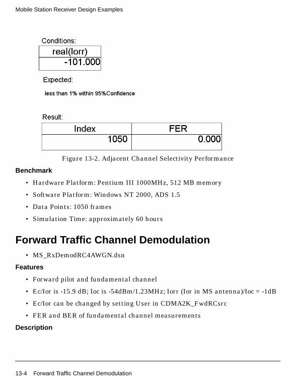
Mobile Station Receiver Design Examples
Figure 13-2. Adjacent Channel Selectivity Performance
Benchmark
• Hardware Platform: Pentium III 1000MHz, 512 MB memory
• Software Platform: Windows NT 2000, ADS 1.5
• Data Points: 1050 frames
• Simulation Time: approximately 60 hours
Forward Traffic Channel Demodulation• MS_RxDemodRC4AWGN.dsn
Features
• Forward pilot and fundamental channel
• Ec/Ior is -15.9 dB; Ioc is -54dBm/1.23MHz; Iorr (Ior in MS antenna)/Ioc = -1dB
• Ec/Ior can be changed by setting User in CDMA2K_FwdRCsrc
• FER and BER of fundamental channel measurements
Description
13-4 Forward Traffic Channel Demodulation

This example verifies the demodulation performance of forward traffic channel underAWGN conditions, as defined in section 3.4.1 of 3GPP2 C.S0011-A. RC4 is used as anexample.
Schematic
Figure 13-3. MS_RxDemodRC4AWGN.dsn Schematic
Notes
User can set up the system parameters or replace a component according to theirparticular requirements.
Simulation Results
Simulation results displayed in MS_RxDemodRC4AWGN.dds are shown inFigure 13-4.
Forward Traffic Channel Demodulation 13-5
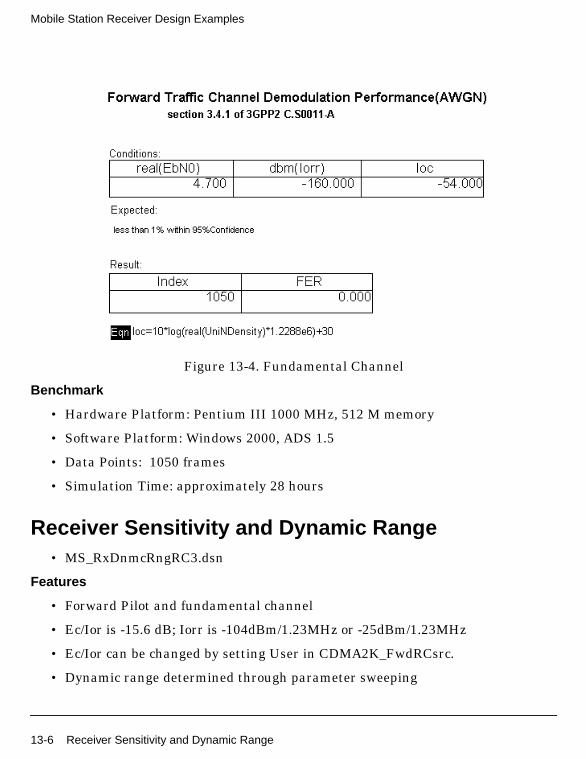
Mobile Station Receiver Design Examples
Figure 13-4. Fundamental Channel
Benchmark
• Hardware Platform: Pentium III 1000 MHz, 512 M memory
• Software Platform: Windows 2000, ADS 1.5
• Data Points: 1050 frames
• Simulation Time: approximately 28 hours
Receiver Sensitivity and Dynamic Range• MS_RxDnmcRngRC3.dsn
Features
• Forward Pilot and fundamental channel
• Ec/Ior is -15.6 dB; Iorr is -104dBm/1.23MHz or -25dBm/1.23MHz
• Ec/Ior can be changed by setting User in CDMA2K_FwdRCsrc.
• Dynamic range determined through parameter sweeping
13-6 Receiver Sensitivity and Dynamic Range

• FER and BER of fundamental channel measurements
Description
This example verifies the receiver sensitivity and dynamic range, as defined insection 3.5.1 of 3GPP2 C.S0011-A. RC3 is used as an example.
Schematic
Figure 13-5. MS_RxDnmcRngRC3.dsn Schematic
Notes
Both receiver sensitivity and dynamic range can be measured using this design. Thedynamic range can be measured through changing the signal power at receiver side.
Simulation Results
Simulation results displayed in MS_RxDnmcRngRC3.dds are shown in Figure 13-6.
Receiver Sensitivity and Dynamic Range 13-7

Mobile Station Receiver Design Examples
Figure 13-6. Receiver Sensitivity and Dynamic Range Simulation Results
Benchmark
• Hardware Platform: Pentium II 400 MHz, 512 MB memory
• Software Platform: Windows NT 4.0 Workstation, ADS 1.5
• Data Points: 1050 frames.
• Simulation Time: approximately 44 hours
Intermodulation Spurious Response Attenuation• MS_RxIntermodulationRC3.dsn
Features
• Forward pilot and fundamental channel
• Ec/Ior is -15.6 dB; Iorr is -101dBm/1.23MHz
• Ec/Ior can be changed by setting User in CDMA2K_FwdRCsrc
• FER and BER of fundamental channel measurements
Description
This example verifies a receiver's ability to receive a CDMA signal on its assignedchannel frequency in the presence of two interfering CW tones, as defined in section3.5.3 of 3GPP2 C.S0011-A. RC3 is used as an example.
13-8 Intermodulation Spurious Response Attenuation

Schematic
Figure 13-7. MS_RxIntermodulationRC3.dsn Schematic
Simulation Results
Simulation results displayed in MS_RxIntermodulationRC3.dds are shown inFigure 13-7.
Intermodulation Spurious Response Attenuation 13-9
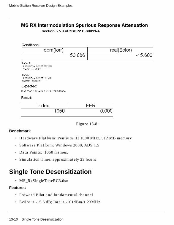
Mobile Station Receiver Design Examples
.
Figure 13-8.
Benchmark
• Hardware Platform: Pentium III 1000 MHz, 512 MB memory
• Software Platform: Windows 2000, ADS 1.5
• Data Points: 1050 frames.
• Simulation Time: approximately 23 hours
Single Tone Desensitization• MS_RxSingleToneRC3.dsn
Features
• Forward Pilot and fundamental channel
• Ec/Ior is -15.6 dB; Iorr is -101dBm/1.23MHz
13-10 Single Tone Desensitization
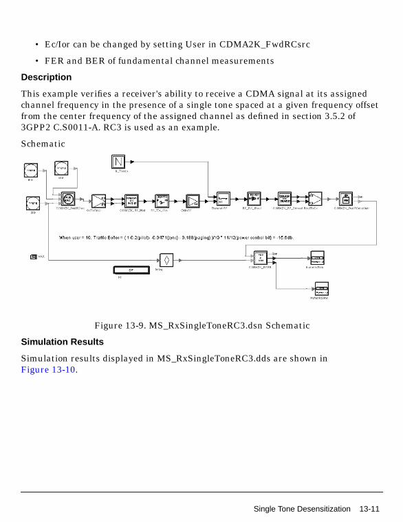
• Ec/Ior can be changed by setting User in CDMA2K_FwdRCsrc
• FER and BER of fundamental channel measurements
Description
This example verifies a receiver's ability to receive a CDMA signal at its assignedchannel frequency in the presence of a single tone spaced at a given frequency offsetfrom the center frequency of the assigned channel as defined in section 3.5.2 of3GPP2 C.S0011-A. RC3 is used as an example.
Schematic
Figure 13-9. MS_RxSingleToneRC3.dsn Schematic
Simulation Results
Simulation results displayed in MS_RxSingleToneRC3.dds are shown inFigure 13-10.
Single Tone Desensitization 13-11
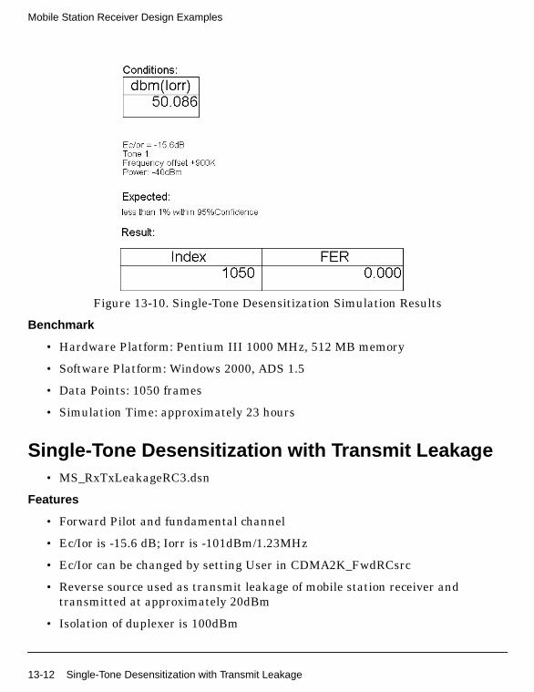
Mobile Station Receiver Design Examples
Figure 13-10. Single-Tone Desensitization Simulation Results
Benchmark
• Hardware Platform: Pentium III 1000 MHz, 512 MB memory
• Software Platform: Windows 2000, ADS 1.5
• Data Points: 1050 frames
• Simulation Time: approximately 23 hours
Single-Tone Desensitization with Transmit Leakage• MS_RxTxLeakageRC3.dsn
Features
• Forward Pilot and fundamental channel
• Ec/Ior is -15.6 dB; Iorr is -101dBm/1.23MHz
• Ec/Ior can be changed by setting User in CDMA2K_FwdRCsrc
• Reverse source used as transmit leakage of mobile station receiver andtransmitted at approximately 20dBm
• Isolation of duplexer is 100dBm
13-12 Single-Tone Desensitization with Transmit Leakage
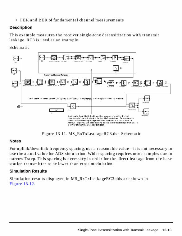
• FER and BER of fundamental channel measurements
Description
This example measures the receiver single-tone desensitization with transmitleakage. RC3 is used as an example.
Schematic
Figure 13-11. MS_RxTxLeakageRC3.dsn Schematic
Notes
For uplink/downlink frequency spacing, use a reasonable value—it is not necessary touse the actual value for ADS simulation. Wider spacing requires more samples due tonarrow Tstep. This spacing is necessary in order for the direct leakage from the basestation transmitter to be lower than cross modulation.
Simulation Results
Simulation results displayed in MS_RxTxLeakageRC3.dds are shown inFigure 13-12.
Single-Tone Desensitization with Transmit Leakage 13-13
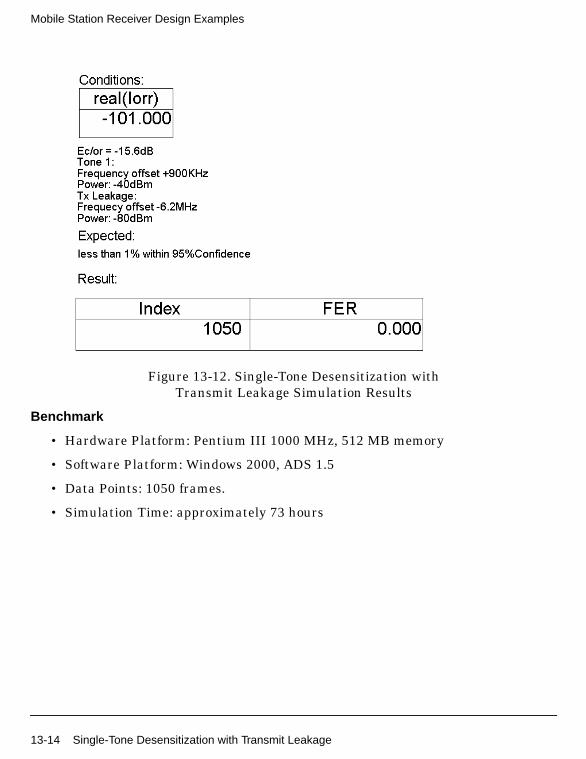
Mobile Station Receiver Design Examples
Figure 13-12. Single-Tone Desensitization withTransmit Leakage Simulation Results
Benchmark
• Hardware Platform: Pentium III 1000 MHz, 512 MB memory
• Software Platform: Windows 2000, ADS 1.5
• Data Points: 1050 frames.
• Simulation Time: approximately 73 hours
13-14 Single-Tone Desensitization with Transmit Leakage
Chapter 14: Mobile Station TransmitterDesign Examples
IntroductionThe MS_TX_prj project shows cdma2000 mobile station transmitter measurementcharacteristics, including waveform quality (rho), mean power, code channel toreverse pilot channel output power accuracy, code domain power and conductedspurious emissions. Designs for these measurements include:
• MS_TxCDP_RC3 for code domain power
• MS_TxMeanPowerSR1.dsn for mean power measurement of RF output
• MS_TxPowerAccuracy.dsn for measurement of code channel to reverse pilotchannel output power accuracy
• MS_TxRhoRC3.dsn for waveform quality measurement
• MS_TxSR1Spectrum.dsn for conducted spurious emissions measurement
Designs under this project consist of:
• MS signal source in baseband
CDMA2K_RevRCsrc provides the uplink signal source of different RadioConfigurations and data rates.
• Transmit modulation and up-convertor
The data source of base band output from CDMA2K_RevRCsrc is up-convertedto IF signal with CDMA2K_RF_Mod, then modulated into RF signal withRF_TX_IFin.
• Code domain power measurement
CDMA2K_CDP is used to measure the code domain power.
• Mean power measurement
CDMA2K_PwrMeasure is used to measure the mean power of input signal.
• Rho measurement
CDMA2K_RevRhoWithRef is used to measure the waveform quality.
Introduction 14-1

Mobile Station Transmitter Design Examples
Code Domain Power• MS_TxCDP_RC3.dsn
Features
• Walsh length is variable
• Reverse pilot and fundamental channels enabled
• Code domain powers for different Walsh length measurements
Description
This example measures the code domain power of RC3 for the reverse link, as definedin section 4.3.3 of 3GPP2 C.S0011-A.
Schematic
Figure 14-1. MS_TxCDP_RC3.dsn Schematic
Simulation Results
Simulation results displayed in MS_TxCDP_RC3.dds are shown in Figure 14-2.
14-2 Code Domain Power
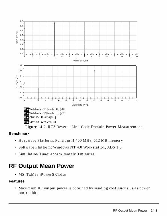
Figure 14-2. RC3 Reverse Link Code Domain Power Measurement
Benchmark
• Hardware Platform: Pentium II 400 MHz, 512 MB memory
• Software Platform: Windows NT 4.0 Workstation, ADS 1.5
• Simulation Time: approximately 3 minutes
RF Output Mean Power• MS_TxMeanPowerSR1.dsn
Features
• Maximum RF output power is obtained by sending continuous 0s as powercontrol bits
RF Output Mean Power 14-3

Mobile Station Transmitter Design Examples
• Minimum controlled output power is obtained by sending continuous 1s aspower control bits
• Total transmit power measurement
Description
This example measures the mobile station transmit mean power as defined insections 4.4.5 and 4.4.6 of 3GPP2 C.S0010-A.
Schematic
Figure 14-3. MS_TxMeanPowerSR1.dsn Schematic
Simulation Results
Simulation results displayed in MS_TxMeanPowerSR1.dds are shown in Figure 14-4.
14-4 RF Output Mean Power
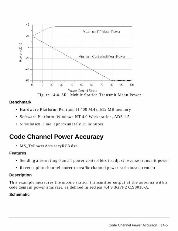
Figure 14-4. SR1 Mobile Station Transmit Mean Power
Benchmark
• Hardware Platform: Pentium II 400 MHz, 512 MB memory
• Software Platform: Windows NT 4.0 Workstation, ADS 1.5
• Simulation Time: approximately 15 minutes
Code Channel Power Accuracy• MS_TxPowerAccuracyRC3.dsn
Features
• Sending alternating 0 and 1 power control bits to adjust reverse transmit power
• Reverse pilot channel power to traffic channel power ratio measurement
Description
This example measures the mobile station transmitter output at the antenna with acode domain power analyzer, as defined in section 4.4.9 3GPP2 C.S0010-A.
Schematic
Code Channel Power Accuracy 14-5
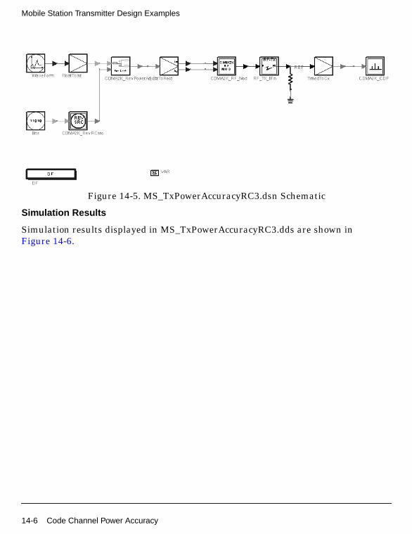
Mobile Station Transmitter Design Examples
Figure 14-5. MS_TxPowerAccuracyRC3.dsn Schematic
Simulation Results
Simulation results displayed in MS_TxPowerAccuracyRC3.dds are shown inFigure 14-6.
14-6 Code Channel Power Accuracy

Figure 14-6. Mobile Station Code Channel Accuracy
Benchmark
• Hardware Platform: Pentium II 400 MHz, 512 MB memory
• Software Platform: Windows NT 4.0 Workstation, ADS 1.5
• Simulation Time: approximately 5 minutes
Waveform Quality• MS_TxRhoRC3.dsn
Features
• Reverse pilot channel and fundamental channel are transmitted
• Normalized correlated power (rho) measurement
Description
Waveform Quality 14-7

Mobile Station Transmitter Design Examples
This example measures the normalized correlated power, rho, for the reverse link, asdefined in section 4.2.2 of 3GPP2 C.S0011-A.
Schematic
Figure 14-7. MS_TxRhoRC3.dsn Schematic
Simulation Results
Simulation results displayed in MS_TxRhoRC3.dds are shown in Figure 14-8.
Figure 14-8. RC3 Reverse Link Measurement
Benchmark
• Hardware Platform: Pentium II 400 MHz, 512 MB memory
• Software Platform: Windows NT 4.0 Workstation, ADS 1.5
• Simulation Time: approximately 2 minutes
Spurious Emissions• MS_TxSR1Spectrum.dsn
Features
• Continuous 0 power control bits sent to adjust mobile station transmit power
• Emission at frequencies outside assigned CDMA channel for SR1 is measured
14-8 Spurious Emissions

Description
This example measures the emission at frequencies that are outside the assignedCDMA channel for SR1 as defined in section 4.5, 3GPP2 C.S0011-A.
Schematic
Figure 14-9. MS_TxSR1Spectrum.dsn Schematic
Simulation Results
Simulation results displayed in MS_TxSR1Spectrum.dds are shown in Figure 14-10.
Spurious Emissions 14-9

Mobile Station Transmitter Design Examples
Figure 14-10. Emission Measurements
Benchmark
• Hardware Platform: Pentium II 400 MHz, 512 MB memory
• Software Platform: Windows NT 4.0 Workstation, ADS 1.5
• Simulation Time: approximately 3 minutes
14-10 Spurious Emissions
Chapter 15: RC_TD Design Examples
IntroductionThe CDMA2K_RC_TD_prj project shows examples for measuring forward andreverse link RC3, including AWGN channel, and multipath fading channel BER andFER. The following sections describe the designs and provide schematics andsimulation results.
BER and FER of Forward Link Radio Configuration 3• DsnCDMA2K_FwdRC3AWGN.dsn
• DsnCDMA2K_FwdRC3DS.dsn
Features
• Constant data rate 9600 bps and 20 msec frame
• Convolutional encoder and Viterbi decoder
• QPSK modulation
• 1.2288 Mcps chip rate
• AWGN channel and multipath fading channel
• Rake receiver for forward traffic channel
• BER and FER values
• Performance curve
Description
DsnCDMA2K_FwdRC3AWGN.dsn and DsnCDMA2K_FwdRC3DS.dsn exampledesigns for measuring forward link RC3 in AWGN and multipath fading channelBER and FER performance, respectively.
Schematics
The schematics for DsnCDMA2K_FwdRC3AWGN.dsn andDsnCDMA2K_FwdRC3DS.dsn are shown in Figure 15-1 and Figure 15-2,respectively.
Introduction 15-1
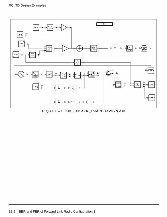
RC_TD Design Examples
Figure 15-1. DsnCDMA2K_FwdRC3AWGN.dsn
15-2 BER and FER of Forward Link Radio Configuration 3

Figure 15-2. DsnCDMA2K_FwdRC3DS.dsn
Subnetworks FwdRC3_ChannelCoding.dsn, FwdRC3_Receiver.dsn,FwdRC3_ChannelDecoding.dsn and FwdRC3_Transmission.dsn were designed forthese examples.
• FwdRC3_ChannelCoding.dsn: channel coding includes CRC encoder, addingtail, convolutional encoder and interleaver.
(Forward Fundamental Channel and Forward Supplemental Channel Structurefor RC3 are given in Reference [1] figures 3.1.3.1.1.1-13.)
Specific parameter settings for this subnetwork are
• InputFrameLen (CDMA2K_CRC_Coder): 172
• CRCType (CDMA2K_CRC_Coder): CRC12 0x1f13
• CCType (CDMA2K_CC_WithTail): rate 1/4 K 9 g0 0765 g1 0671 g2 0513 g3 0473
• BlockRow_m and BlockColumn_J (CDMA2K_BlockIntlvr): m=6, J=12
• IntlvrType (CDMA2K_BlockIntlvr): Fwd_Backwards
BER and FER of Forward Link Radio Configuration 3 15-3
RC_TD Design Examples
• FwdRC3_ChannelDeCoding.dsn: channel decoding includes de-interleaver,Viterbi decoder, CRC check and erasing tail.
Specific parameter settings for this subnetwork are
• InputFrameLen (CDMA2K_CRC_DeCoder): 184
• CRCType (CDMA2K_CRC_DeCoder): CRC12 0x1f13
• CCType (CDMA2K_DCC_WithTail): rate 1/4 K 9 g0 0765 g1 0671 g2 0513 g30473
• BlockRow_m and BlockColumn_J (CDMA2K_DeBlockIntlvr): m=6, J=12
• IntlvrType (CDMA2K_BlockDeIntlvr): Fwd_Backwards
• FwdRC3_Receiver.dsn: Rake receiver for RC3 includes forward Rake and Walshand PN function generators. It includes a TrafficIndex parameter (the Walshfunction index used in the Traffic Channel) and a PilotType parameter withpilot or transmit diversity pilot options (Pilot is used for this example).
Specific parameter settings for this subnetwork are
• SpreadRate (CDMA2K_FwdRake): SR1
• PilotWalshLen (CDMA2K_FwdRake): 128
• TrafficWalshLen (CDMA2K_FwdRake): 64
• FrameLength (CDMA2K_FwdRake): 384
• FingerNum (CDMA2K_FwdRake): 1 (AWGN), 3 (Multipath fading channel)(This parameter value must be checked before simulation.)
• WalshLength (CDMA2K_VL_Walsh): 128 (for Pilot channel), 64 (for Trafficchannel)
• FwdRC3_Transmission.dsn: transmission includes data scrambling, insertingPC bits, Walsh modulator and Walsh rotator.
(Long Code Scrambling, Power Control, and Signal Point Mapping for ForwardTraffic Channels with RC3, RC4, and RC5 are performed and shown in Ref [1]figures 3.1.3.1.1.1-16. I and Q Mapping (non-OTD mode) for SRate1 areperformed and shown in Ref [1] figures 3.1.3.1.1.1-18.)
Specific parameter settings for this subnetwork are
• RadioConfig (CDMA2K_DataScrambling): RC3 to RC9 Non OTD
• RadioConfig (CDMA2K_FwdPCBitPuncture): RC3 Non OTD
15-4 BER and FER of Forward Link Radio Configuration 3

• WalshLength (CDMA2K_WalshModulator): 64
Simulation Results
A constant 9600 bps data rate frame is used as source. The ratio of traffic to pilotpower is −8.3dB. The multipath channel model is Vehicular Test Environment,Channel A. The carrier frequency is 825 MHz; mobile speed is 120 km/hour.
Note that noise is band limited, and its bandwidth is 4 times the bandwidth of thebaseband filter. When Eb/Nt is calculated, only the inband noise power is considered.For example if the noise power (2*variance) is set as 100, the inband noise power isset as 25, the real noise power equals the measured noise power PN − 6dB.
The following equation is from TIA/EIA/IS-98-A, pp. 1-12 to 1-14 (Reference [2]):
.
In this example, for AWGN channel, transmit power equals received power. For RC320msec frames without channel coding, processing gain equals 128 (21.1dB).
Eb/Nt= dB(Processing Gain) - dB(No) + 6.
Table 15-1 and Figure 15-3 show BER and FER performance for different Eb/Ntunder AWGN. Table 15-2 and Figure 15-4 show BER and FER performance indifferent Eb/Nt in multipath fading channel.
Table 15-1. AWGN BER and FER
Eb/Nt(dB) BER FER
−0.618 0.067% 2.5%
−0.358 0.03435% 1.32%
−0.118 0.0152% 0.57%
0.132 0.00765% 0.317%
0.382 0.00226% 0.0936%
EbNt-------
TrafficEcTotalTransPowerSpecDensity------------------------------------------------------------------------------------------ Proces gGainsin×
BandlimitedAWGNPowerSpecDensity No( )ReceivedPowerSpecDensity
---------------------------------------------------------------------------------------------------------------------------------
------------------------------------------------------------------------------------------------------------------------------------------------=
No2
-------- σ2=
BER and FER of Forward Link Radio Configuration 3 15-5
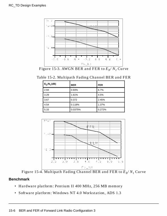
RC_TD Design Examples
Figure 15-3. AWGN BER and FER to Eb/Nt Curve
Figure 15-4. Multipath Fading Channel BER and FER to Eb/Nt Curve
Benchmark
• Hardware platform: Pentium II 400 MHz, 256 MB memory
• Software platform: Windows NT 4.0 Workstation, ADS 1.3
Table 15-2. Multipath Fading Channel BER and FER
Eb/Nt(dB) BER FER
2.94 0.93% 6.7%
3.29 1.61% 4.5%
3.67 0.372 2.45%
4.54 0.118% 1.37%
5.33 0.0375% 0.272%
15-6 BER and FER of Forward Link Radio Configuration 3

• Data points: 1000 frames
• Simulation time: approximately 10 hours for AWGN; 24 hours for multipathfading channel
Notes
TkShowValues is used in this example. FER, BER, and Tested frames are displayedduring simulation; values are displayed in the Ptolemy Control Panel window. Theuser can control the number of bits to be tested; lower FER and BER may result bytesting more bits.
References
[1] IS2000.2, Physical Layer Standard for cdma2000 Spread Spectrum Systems,April 1999.
[2] TIA/EIA/IS-98-A, Recommended Minimum Performance Standards forDual-Mode Wideband Spread Spectrum Cellular Mobile Stations, July 1996.
BER and FER of Forward Link Radio Configuration 3with OTD ModeCDMA2K_RC_TD_prj Design Name
• DsnCDMA2K_FwdRC3OTD.dsn
Features
• Constant data rate 9600 bps and 20 msec frame
• Pilot and transmit diversity pilot channel
• Convolutional encoder and Viterbi decoder
• QPSK modulation
• 1.2288 Mcps chip rate
• Multipath fading channel
• Orthogonal transmission diversity
• Rake receiver for forward traffic channel
• BER and FER values
• Performance curve
BER and FER of Forward Link Radio Configuration 3 with OTD Mode 15-7

RC_TD Design Examples
Description
DsnCDMA2K_FwdRC3OTD.dsn is an example design for measuring forward linkRC3 OTD mode in multipath fading channel BER and FER performance.
Schematic
The schematic for this design is shown in Figure 15-5.
Figure 15-5. DsnCDMA2K_FwdRC3OTD.dsn
Subnetworks FwdRC3_ChannelCoding, FwdRC3_ChannelDecoding,FwdRC3_Receiver, FwdRC3OTD_Multiplex and FwdRC3OTD_Transmission weredesigned for this example.
• FwdRC3_ChannelCoding: channel coding includes CRC encoder, adding tail,convolutional encoder and interleaver.
Specific parameter settings for this subnetwork are
• InputFrameLen (CDMA2K_CRC_Coder): 172
• CRCType (CDMA2K_CRC_Coder): CRC12 0x1f13
• CCType (CDMA2K_CC_WithTail): rate 1/4 K 9 g0 0765 g1 0671 g2 0513 g3 0473
15-8 BER and FER of Forward Link Radio Configuration 3 with OTD Mode
• BlockRow_m and BlockColumn_J (CDMA2K_BlockIntlvr): m=6, J=12
• IntlvrType (CDMA2K_BlockIntlvr): Fwd_Backwards
• FwdRC3_ChannelDeCoding.dsn: channel decoding includes de-interleaver,Viterbi decoder, CRC check and erasing tail.
Specific parameter settings for this subnetwork are
• InputFrameLen (CDMA2K_CRC_DeCoder): 184
• CRCType (CDMA2K_CRC_DeCoder): CRC12 0x1f13
• CCType (CDMA2K_DCC_WithTail): rate 1/4 K 9 g0 0765 g1 0671 g2 0513 g30473
• BlockRow_m and BlockColumn_J (CDMA2K_BlockDeIntlvr): m=6, J=12
• IntlvrType (CDMA2K_BlockDeIntlvr): Fwd_Backwards
• FwdRC3OTD_Multiplex.dsn: multiplexing the outputs of each Rake receiver.
• FwdRC3_Receiver.dsn: Rake receiver for RC3 includes forward Rake and Walshand PN function generators. It includes a TrafficIndex parameter (the Walshfunction index used in the Traffic Channel) and a PilotType parameter withpilot or transmit diversity pilot options (TDPilot is used for this example).
Specific parameter settings for this subnetwork are
• SpreadRate (CDMA2K_FwdRake): SR1
• PilotWalshLen (CDMA2K_FwdRake): 128
• TrafficWalshLen (CDMA2K_FwdRake): 64
• FrameLength (CDMA2K_FwdRake): 384
• FingerNum (CDMA2K_FwdRake): 3(This parameter must be set to 3 before simulation.)
• WalshLength (CDMA2K_VL_Walsh): 128 (for Pilot channel),64 (for Traffic channel).
• FwdRC3OTD_Transmission.dsn: transmission includes data scrambling,inserting PC bits, Walsh modulator and Walsh rotator.
Specific parameter settings for this subnetwork are
• RadioConfig (CDMA2K_DataScrambling): RC3 to RC9 OTD
• RadioConfig (CDMA2K_FwdPCBitPuncture): RC3 OTD
BER and FER of Forward Link Radio Configuration 3 with OTD Mode 15-9

RC_TD Design Examples
• WalshLength (CDMA2K_WalshModulator): 64
Simulation Results
In this example, constant 9600 bps data rate frame is used as source. The ratio oftraffic power to pilot power is −11.3dB. The multipath channel model is VehicularTest Environment, Channel A. Carrier frequency is 825 MHz and mobile speed is 120km/hour.
Note that noise is band limited, and its bandwidth is 4 times the bandwidth of thebaseband filter. When Eb/Nt is calculated, only the inband noise power is used. Forexample, if noise power (2*variance) is set as 100, then the inband noise power is setas 25, the real noise power equals the measured noise power PN − 6dB.
The following equation is from TIA/EIA/IS-98-A, pp. 1-12 to 1-14 (Reference [2]):
In this example, for AWGN channel, transmit power equals received power. For RC320msec frames, processing gain equals 128 (21.1dB).
Eb/Nt= dB(Processing Gain) - dB(No) + 6.
Under the same channel condition, when FER=1%, the required Eb/Nt isapproximately 4.7dB without OTD, and approximately 2.9dB with OTD. Performanceis increased by 1.8dB with OTD when FER is 1%.
Benchmark
• Hardware platform: Pentium II 400 MHz, 256 MB memory
• Software platform: Windows NT 4.0 workstation, Advanced Design System 1.3
• Data points: 1000 frames
• Simulation time: approximately 48 hours
Notes
EbNt-------
TrafficEcTotalTransPowerSpecDensity------------------------------------------------------------------------------------------ Proces gGainsin×
BandlimitedAWGNPowerSpecDensity N0( )ReceivedPowerSpecDensity
---------------------------------------------------------------------------------------------------------------------------------
------------------------------------------------------------------------------------------------------------------------------------------------=
No2
-------- σ2=
15-10 BER and FER of Forward Link Radio Configuration 3 with OTD Mode
TkShowValues is used in this example. FER, BER, and Tested frames are displayedduring simulation; values are displayed in the Ptolemy Control Panel window. Theuser can control the number of bits to be tested; lower FER and BER may result bytesting more bits.
References
[1] IS2000.2, Physical Layer Standard for cdma2000 Spread Spectrum Systems,April 1999.
[2] TIA/EIA/IS-98-A, Recommended Minimum Performance Standards forDual-Mode Wideband Spread Spectrum Cellular Mobile Stations, July 1996.
BER and FER of Reverse Link Radio Configuration 3CDMA2K_RC_TD_prj Design Name
• DsnCDMA2K_RevRC3AWGN.dsn
• DsnCDMA2K_RevRC3Fade.dsn
Features
• Constant data rate 9600 bps and 20 msec frame
• 1/4 convolutional encoder and Viterbi decoder
• Pilot channel and one fundamental traffic channel
• HPSK modulation
• 1.2288 Mcps chip rate
• AWGN and multipath fading channel
• Rake receiver for reverse traffic channel
• BER and FER values
• Performance curve
Description
DsnCDMA2K_RevRC3AWGN.dsn and DsnCDMA2K_RevRC3Fade.dsn are exampledesigns for measuring BER and FER performance of reverse link RC3 in AWGN andmultipath fading channel, respectively.
Schematic
BER and FER of Reverse Link Radio Configuration 3 15-11
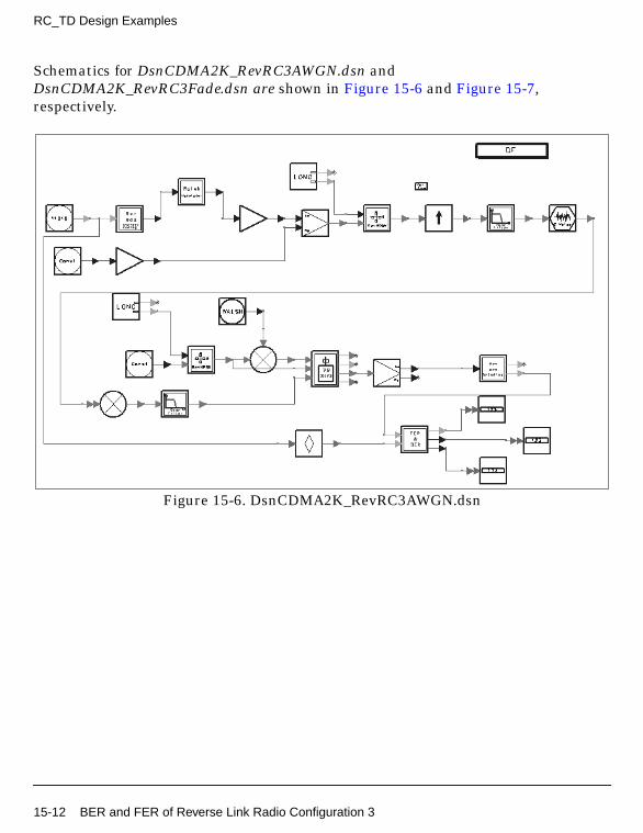
RC_TD Design Examples
Schematics for DsnCDMA2K_RevRC3AWGN.dsn andDsnCDMA2K_RevRC3Fade.dsn are shown in Figure 15-6 and Figure 15-7,respectively.
Figure 15-6. DsnCDMA2K_RevRC3AWGN.dsn
15-12 BER and FER of Reverse Link Radio Configuration 3
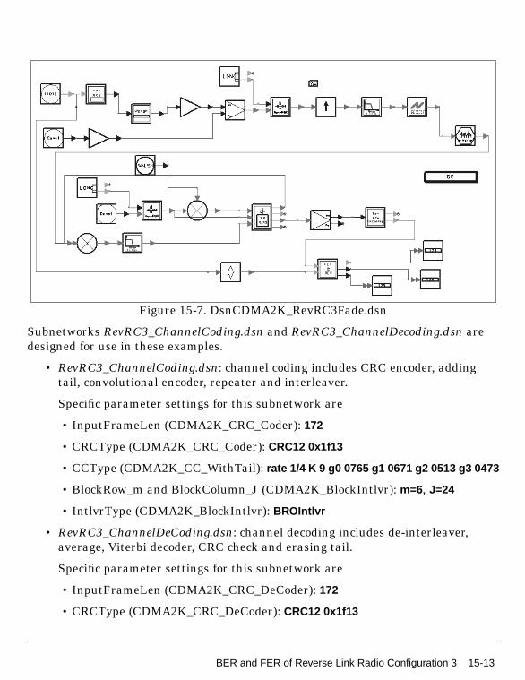
Figure 15-7. DsnCDMA2K_RevRC3Fade.dsn
Subnetworks RevRC3_ChannelCoding.dsn and RevRC3_ChannelDecoding.dsn aredesigned for use in these examples.
• RevRC3_ChannelCoding.dsn: channel coding includes CRC encoder, addingtail, convolutional encoder, repeater and interleaver.
Specific parameter settings for this subnetwork are
• InputFrameLen (CDMA2K_CRC_Coder): 172
• CRCType (CDMA2K_CRC_Coder): CRC12 0x1f13
• CCType (CDMA2K_CC_WithTail): rate 1/4 K 9 g0 0765 g1 0671 g2 0513 g3 0473
• BlockRow_m and BlockColumn_J (CDMA2K_BlockIntlvr): m=6, J=24
• IntlvrType (CDMA2K_BlockIntlvr): BROIntlvr
• RevRC3_ChannelDeCoding.dsn: channel decoding includes de-interleaver,average, Viterbi decoder, CRC check and erasing tail.
Specific parameter settings for this subnetwork are
• InputFrameLen (CDMA2K_CRC_DeCoder): 172
• CRCType (CDMA2K_CRC_DeCoder): CRC12 0x1f13
BER and FER of Reverse Link Radio Configuration 3 15-13
RC_TD Design Examples
• CCType (CDMA2K_DCC_WithTail): rate 1/4 K 9 g0 0765 g1 0671 g2 0513 g30473
• BlockRow_m and BlockColumn_J (CDMA2K_BlockDeIntlvr): m=6, J=24
• IntlvrType (CDMA2K_BlockDeIntlvr): BROIntlvr
Specific parameter settings for CDMA2K_RevRake in these subnetworks are:
• SpreadRate: SR1
• TrafficWalshLen: 16
• FrameLength: 1536
• FingerNum: 1 (AWGN), 3 (multipath fading channel)
Simulation Results
In this example, constant 9600 bps data rate frame is used as source. The ratio oftraffic power to pilot power is 3.75 dB. The multipath channel model is Vehicular TestEnvironment, Channel A. Carrier frequency is 825 MHz; mobile speed is 120km/hour.
Note that noise is band limited, and its bandwidth is 4 times the bandwidth of thebaseband filter. When Eb/Nt is calculated, only the inband noise power is used. Forexample, if the noise power (2*variance) is set as 100, the inband noise power is setas 25, the real noise power equals the measured noise power PN − 6dB.
The following equation is from TIA/EIA/IS-98-A, pp. 1-12 to 1-14 (Reference [2]):
In this example, for AWGN channel, transmit power equals received power. For RC320msec frames, processing gain equals 128 (21.1dB).
Eb/Nt= dB(Processing Gain) - dB(No) + 6.
EbNt-------
TrafficEcTotalTransPowerSpecDensity------------------------------------------------------------------------------------------ Proces gGainsin×
BandlimitedAWGNPowerSpecDensity N0( )ReceivedPowerSpecDensity
---------------------------------------------------------------------------------------------------------------------------------
------------------------------------------------------------------------------------------------------------------------------------------------=
No2
-------- σ2=
15-14 BER and FER of Reverse Link Radio Configuration 3
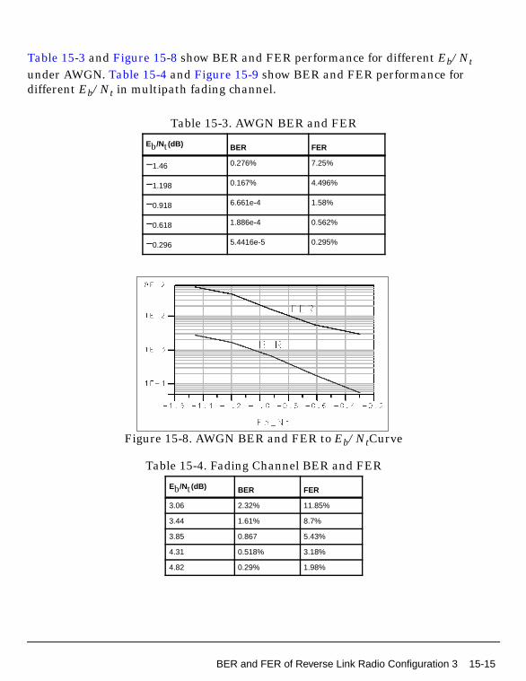
Table 15-3 and Figure 15-8 show BER and FER performance for different Eb/Ntunder AWGN. Table 15-4 and Figure 15-9 show BER and FER performance fordifferent Eb/Nt in multipath fading channel.
Figure 15-8. AWGN BER and FER to Eb/NtCurve
Table 15-3. AWGN BER and FER
Eb/Nt(dB) BER FER
−1.46 0.276% 7.25%
−1.198 0.167% 4.496%
−0.918 6.661e-4 1.58%
−0.618 1.886e-4 0.562%
−0.296 5.4416e-5 0.295%
Table 15-4. Fading Channel BER and FER
Eb/Nt(dB) BER FER
3.06 2.32% 11.85%
3.44 1.61% 8.7%
3.85 0.867 5.43%
4.31 0.518% 3.18%
4.82 0.29% 1.98%
BER and FER of Reverse Link Radio Configuration 3 15-15
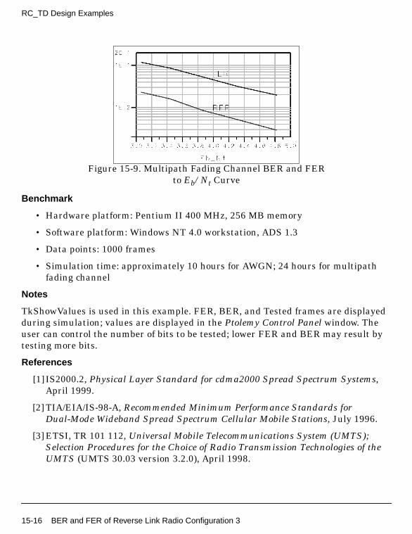
RC_TD Design Examples
Figure 15-9. Multipath Fading Channel BER and FERto Eb/Nt Curve
Benchmark
• Hardware platform: Pentium II 400 MHz, 256 MB memory
• Software platform: Windows NT 4.0 workstation, ADS 1.3
• Data points: 1000 frames
• Simulation time: approximately 10 hours for AWGN; 24 hours for multipathfading channel
Notes
TkShowValues is used in this example. FER, BER, and Tested frames are displayedduring simulation; values are displayed in the Ptolemy Control Panel window. Theuser can control the number of bits to be tested; lower FER and BER may result bytesting more bits.
References
[1] IS2000.2, Physical Layer Standard for cdma2000 Spread Spectrum Systems,April 1999.
[2] TIA/EIA/IS-98-A, Recommended Minimum Performance Standards forDual-Mode Wideband Spread Spectrum Cellular Mobile Stations, July 1996.
[3] ETSI, TR 101 112, Universal Mobile Telecommunications System (UMTS);Selection Procedures for the Choice of Radio Transmission Technologies of theUMTS (UMTS 30.03 version 3.2.0), April 1998.
15-16 BER and FER of Reverse Link Radio Configuration 3
BER and FER AWGN of Forward Link RadioConfiguration 6CDMA2K_RC_TD_prj Design Name
• DsnCDMA2K_FwdRC6AWGN.dsn
Features
• Constant data rate 9600 bps and 20 msec frame
• Convolutional encoder and Viterbi decoder
• QPSK modulation
• 3.6864 Mcps chip rate
• AWGN channel
• Rake receiver for forward traffic channel
• BER and FER values
• Performance curve
Description
DsnCDMA2K_FwdRC6AWGN.dsn is an example designed for measuring BER andFER performance of forward link RC6 in AWGN channel.
Schematic
The schematic for this design is shown in Figure 15-10.
BER and FER AWGN of Forward Link Radio Configuration 6 15-17
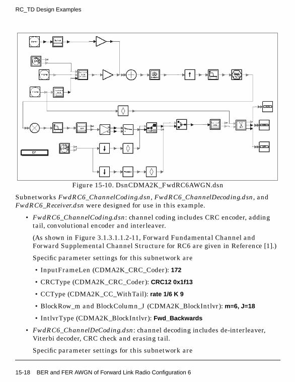
RC_TD Design Examples
Figure 15-10. DsnCDMA2K_FwdRC6AWGN.dsn
Subnetworks FwdRC6_ChannelCoding.dsn, FwdRC6_ChannelDecoding.dsn, andFwdRC6_Receiver.dsn were designed for use in this example.
• FwdRC6_ChannelCoding.dsn: channel coding includes CRC encoder, addingtail, convolutional encoder and interleaver.
(As shown in Figure 3.1.3.1.1.2-11, Forward Fundamental Channel andForward Supplemental Channel Structure for RC6 are given in Reference [1].)
Specific parameter settings for this subnetwork are
• InputFrameLen (CDMA2K_CRC_Coder): 172
• CRCType (CDMA2K_CRC_Coder): CRC12 0x1f13
• CCType (CDMA2K_CC_WithTail): rate 1/6 K 9
• BlockRow_m and BlockColumn_J (CDMA2K_BlockIntlvr): m=6, J=18
• IntlvrType (CDMA2K_BlockIntlvr): Fwd_Backwards
• FwdRC6_ChannelDeCoding.dsn: channel decoding includes de-interleaver,Viterbi decoder, CRC check and erasing tail.
Specific parameter settings for this subnetwork are
15-18 BER and FER AWGN of Forward Link Radio Configuration 6

• InputFrameLen (CDMA2K_CRC_DeCoder): 184
• CRCType (CDMA2K_CRC_DeCoder): CRC12 0x1f13
• CCType (CDMA2K_DCC_WithTail): rate 1/6 K 9
• BlockRow_m and BlockColumn_J (CDMA2K_DeBlockIntlvr): m=6, J=18
• IntlvrType (CDMA2K_DeBlockIntlvr): Fwd_Backwards
• FwdRC6_Receiver.dsn: Rake receiver for RC6 includes forward Rake and Walshand PN function generators. It includes a TrafficIndex parameter (the Walshfunction index used in the Traffic Channel) and a PilotType parameter withpilot or transmit diversity pilot options (Pilot is used for this example).
Specific parameter settings for this subnetwork are
• SpreadRate (CDMA2K_FwdRake): SR3
• PilotWalshLen (CDMA2K_FwdRake):128
• TrafficWalshLen (CDMA2K_FwdRake):128
• FrameLength (CDMA2K_FwdRake): 576
• FingerNum (CDMA2K_FwdRake): 1
• FwdRC6_Transmission.dsn: transmission includes data scrambling, insertingPC bits, Walsh modulator and Walsh rotator.
Specific parameter settings for this subnetwork are
• RadioConfig (CDMA2K_DataScrambling): RC3 to RC9 Non OTD
• RadioConfig (CDMA2K_FwdPCBitPuncture): RC6 Non OTD
• WalshLength (CDMA2K_WalshModulator): 128
Simulation Results
In this example, constant 9600 bps data rate frame is used as source. The ratio oftraffic power to pilot power is −8.3dB.
Note that noise is band limited, and its bandwidth is 4 times the bandwidth of thebaseband filter. When Eb/Nt is calculated, only the inband noise power is used. Forexample, if noise power (2*variance) is set as 100, the inband noise power is set as 25,the real noise power equals the measured noise power PN − 6dB.
The following equation is from TIA/EIA/IS-98-A, pp. 1-12 to 1-14 (Reference [2]):
BER and FER AWGN of Forward Link Radio Configuration 6 15-19
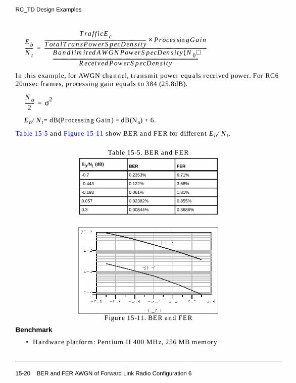
RC_TD Design Examples
In this example, for AWGN channel, transmit power equals received power. For RC620msec frames, processing gain equals to 384 (25.8dB).
Eb/Nt= dB(Processing Gain) − dB(No) + 6.
Table 15-5 and Figure 15-11 show BER and FER for different Eb/Nt.
Figure 15-11. BER and FER
Benchmark
• Hardware platform: Pentium II 400 MHz, 256 MB memory
Table 15-5. BER and FER
Eb/Nt (dB) BER FER
-0.7 0.2353% 6.71%
-0.443 0.122% 3.68%
-0.193 0.061% 1.81%
0.057 0.02382% 0.855%
0.3 0.00844% 0.3686%
EbNt-------
TrafficEcTotalTransPowerSpecDensity------------------------------------------------------------------------------------------ Proces gGainsin×
BandlimitedAWGNPowerSpecDensity N0( )ReceivedPowerSpecDensity
---------------------------------------------------------------------------------------------------------------------------------
------------------------------------------------------------------------------------------------------------------------------------------------=
No2
-------- σ2=
15-20 BER and FER AWGN of Forward Link Radio Configuration 6
• Software platform: Windows NT 4.0 workstation, ADS 1.3
• Data points: 1000 frames
• Simulation time: approximately 14 hours
Notes
TkShowValues is used in this example. FER, BER, and Tested frames are displayedduring simulation; values are displayed in the Ptolemy Control Panel window. Theuser can control the number of bits to be tested; lower FER and BER may result bytesting more bits.
References
[1] IS2000.2, Physical Layer Standard for cdma2000 Spread Spectrum Systems,April 1999.
[2] TIA/EIA/IS-98-A, Recommended Minimum Performance Standards forDual-Mode Wideband Spread Spectrum Cellular Mobile Stations, July 1996.
BER and FER AWGN of Reverse Link RadioConfiguration 6CDMA2K_RC_TD_prj Design Name
• DsnCDMA2K_RevRC6AWGN.dsn
Features
• Constant data rate 14400bps and 20 msec Frame
• 1/4 convolutional encoder and Viterbi decoder
• HPSK modulation
• 3.6864 Mcps chip rate
• AWGN channel
• Rake receiver for reverse traffic channel
• BER and FER values
• Performance curve
Description
BER and FER AWGN of Reverse Link Radio Configuration 6 15-21

RC_TD Design Examples
DsnCDMA2K_RevRC6AWGN.dsn is an example design for measuring BER and FERperformance of reverse linkRC6 in an AWGN channel.
Schematic
The schematic for this design is shown in Figure 15-12.
Figure 15-12. DsnCDMA2K_RevRC6AWGN.dsn
Subnetworks RevRC6_ChannelCoding.dsn and RevRC6_ChannelDecoding.dsn weredesigned for this example.
• RevRC6_ChannelCoding.dsn: channel coding includes CRC encoder, addingtail, convolutional encoder, repeater and interleaver.
Specific parameter settings for this subnetwork are
• InputFrameLen (CDMA2K_CRC_Coder): 268
• CRCType (CDMA2K_CRC_Coder): CRC12 0x1f13
• CCType (CDMA2K_CC_WithTail): rate 1/4 K 9 g0 0765 g1 0671 g2 0513 g3 0473
• BlockRow_m and BlockColumn_J (CDMA2K_BlockIntlvr): m=6, J=24
• IntlvrType (CDMA2K_BlockIntlvr): BROIntlvr
15-22 BER and FER AWGN of Reverse Link Radio Configuration 6

• RevRC6_ChannelDeCoding.dsn: channel decoding includes de-interleaver,average, Viterbi decoder, CRC check and erasing tail.
Specific parameter settings for this subnetwork are
• InputFrameLen (CDMA2K_CRC_DeCoder): 280
• CRCType (CDMA2K_CRC_DeCoder): CRC12 0x1f13
• CCType (CDMA2K_DCC_WithTail): rate 1/4 K 9 g0 0765 g1 0671 g2 0513 g30473
• BlockRow_m and BlockColumn_J (CDMA2K_BlockDeIntlvr): m=6, J=24
• IntlvrType (CDMA2K_BlockDeIntlvr): BROIntlvr
Simulation Results
In this example, constant 14400 bps data rate frame is used as source. The ratio oftraffic power to pilot power is 3.75 dB.
Note that noise is band limited, and its bandwidth is 4 times the bandwidth of thebaseband filter. When Eb/Nt is calculated, only the inband noise power is used. Forexample, if the noise power (2*variance) is set as 100, the inband noise power is setas 25, the real noise power equals the measured noise power PN − 6dB.
The following equation is from TIA/EIA/IS-98-A, pp. 1-12 to 1-14 (Reference [2]):
In this example, for AWGN channel, transmit power equals received power. For RC620msec frames, processing gain equals to 256 (24.1dB).
Eb/Nt= dB(Processing Gain) − dB(No) + 6.
Table 15-6 and Figure 15-13 show BER and FER performances for different Eb/Ntvalues.
EbNt-------
TrafficEcTotalTransPowerSpecDensity------------------------------------------------------------------------------------------ Proces gGainsin×
BandlimitedAWGNPowerSpecDensity N0( )ReceivedPowerSpecDensity
---------------------------------------------------------------------------------------------------------------------------------
------------------------------------------------------------------------------------------------------------------------------------------------=
No2
-------- σ2=
BER and FER AWGN of Reverse Link Radio Configuration 6 15-23

RC_TD Design Examples
Figure 15-13. BER and FER to Eb/Nt Curve
Benchmark
• Hardware platform: Pentium II 400 MHz, 256 MB memory
• Software platform: Windows NT 4.0 workstation, ADS 1.3
• Data points: 1540 frames
• Simulation time: approximately 16 hours
Notes
TkShowValues is used in this example. FER, BER, and Tested frames are displayedduring simulation; values are displayed in the Ptolemy Control Panel window. Theuser can control the number of bits to be tested; lower FER and BER may result bytesting more bits.
References
Table 15-6. BER and FER Performance
Eb/Nt(dB) BER FER
-0.618 0.0548% 2.42%
-0.46 0.0483% 2.27%
-0.296 0.0254% 0.126%
-0.126 0.01% 0.621%
0.05 4.548e-5 0.33%
15-24 BER and FER AWGN of Reverse Link Radio Configuration 6
[1] IS2000.2, Physical Layer Standard for cdma2000 Spread Spectrum Systems,April 1999.
[2] TIA/EIA/IS-98-A, Recommended Minimum Performance Standards forDual-Mode Wideband Spread Spectrum Cellular Mobile Stations, July 1996.
BER and FER of Forward Link Radio Configuration 8with MC ModeCDMA2K_RC_TD_prj Design Name
• DsnCDMA2K_MCRC8.dsn
Features
• Constant data rate 14400 bps and 20 msec frame
• Convolutional encoder and Viterbi decoder
• QPSK modulation
• Three carriers; each with 1.2288 Mcps chip rate
• Bandpass filters separate signals over different carriers
• Rake receiver for signal over each carrier
• BER and FER values
Description
DsnCDMA2K_MCRC8.dsn is an example design for measuring BER and FERperformance of forward link RC8 with multi-carrier mode.
Schematic
The schematic for this design is shown in Figure 15-14.
BER and FER of Forward Link Radio Configuration 8 with MC Mode 15-25

RC_TD Design Examples
Figure 15-14. DsnCDMA2K_MCRC8.dsn
Subnetworks MCRC8_ChannelCoding.dsn, MCRC8_ChannelDecoding.dsn,MCRC8_Multiplex.dsn, MCRC8_Receiver.dsn, and MCRC8_Transmission.dsn weredesigned for use in this example.
• MCRC8_ChannelCoding.dsn: channel coding includes CRC encoder, adding tail,convolutional encoder and interleaver.
Specific parameter settings for this subnetwork are
• InputFrameLen (CDMA2K_CRC_Coder): 268
• CRCType (CDMA2K_CRC_Coder): CRC12 0x1f13
• CCType (CDMA2K_CC_WithTail): rate 1/4 K 9
• BlockRow_m and BlockColumn_J (CDMA2K_MCMode_Intlvr): m=6, J=6
• MCRC8_ChannelDeCoding.dsn: channel decoding includes De-Interleaver,Viterbi decoder, Check CRC and erase tail.
15-26 BER and FER of Forward Link Radio Configuration 8 with MC Mode

Specific parameter settings for this subnetwork are
• InputFrameLen (CDMA2K_CRC_DeCoder): 280
• CRCType (CDMA2K_CRC_DeCoder): CRC12 0x1f13
• CCType (CDMA2K_DCC_WithTail): rate 1/4 K 9
• BlockRow_m and BlockColumn_J (CDMA2K_MCMode_DeIntlvr): m=6, J=6
• MCRC8_Multiplex.dsn: multiplexing the outputs of each Rake receiver ondifferent carriers.
• MCRC8_Receiver.dsn: Rake receiver includes Forward Rake and Walsh and PNFunction generators.
Specific parameter settings for this subnetwork are
• SpreadRate (CDMA2K_FwdRake): SR1
• PilotWalshLen (CDMA2K_FwdRake): 128
• TrafficWalshLen (CDMA2K_FwdRake): 128
• FrameLength (CDMA2K_FwdRake): 192
• FingerNum (CDMA2K_FwdRake): 1
• MCRC8_Transmission.dsn: transmitter includes data scrambling, PC bitpuncture, Walsh modulator and Walsh rotation.
Specific parameter settings for this subnetwork are
• RadioConfig (CDMA2K_DataScrambling): RC3 To RC9 MC
• RadioConfig (CDMA2K_FwdPCBitPuncture): RC8 MC
• WalshLength (CDMA2K_WalshModulator): 128
Simulation Results
The spectrums on the transmitter and on the receiver sides after bandpass filter areshown in Figure 15-15. The first graph shows the transmitter side; the other graphsshow the receiver side with center frequencies of 823.5, 825, and 826.5 MHz.
BER and FER of Forward Link Radio Configuration 8 with MC Mode 15-27
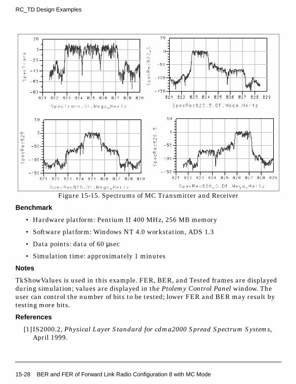
RC_TD Design Examples
Figure 15-15. Spectrums of MC Transmitter and Receiver
Benchmark
• Hardware platform: Pentium II 400 MHz, 256 MB memory
• Software platform: Windows NT 4.0 workstation, ADS 1.3
• Data points: data of 60 µsec
• Simulation time: approximately 1 minutes
Notes
TkShowValues is used in this example. FER, BER, and Tested frames are displayedduring simulation; values are displayed in the Ptolemy Control Panel window. Theuser can control the number of bits to be tested; lower FER and BER may result bytesting more bits.
References
[1] IS2000.2, Physical Layer Standard for cdma2000 Spread Spectrum Systems,April 1999.
15-28 BER and FER of Forward Link Radio Configuration 8 with MC Mode
[2] TIA/EIA/IS-98-A, Recommended Minimum Performance Standards forDual-Mode Wideband Spread Spectrum Cellular Mobile Stations, July 1996.
BER and FER of Forward Link Radio Configuration 8 with MC Mode 15-29
RC_TD Design Examples
15-30 BER and FER of Forward Link Radio Configuration 8 with MC Mode

Chapter 16: Rake Design Examples
IntroductionThe CDMA2K_Rake_prj project shows examples for measuring forward and reverselink Rake receiver BER performance. The following sections describe the designs andprovide schematics and simulation results.
BER of Forward Link Rake Receiver• DsnCDMA2K_FwdRake.dsn
Features
• QPSK modulation
• 1.2288 Mcps chip rate
• AWGN and fading channel
• Rake receiver for forward traffic channel
• BER value
• Performance curve
Description
DsnCDMA2K_FwdRake.dsn is an example design for measuring forward link Rakereceiver BER performance.
Schematic
The schematic for this design is shown in Figure 16-1.
Specific parameter settings are
• WalshLength (CDMA2K_WalshModulator): 64
• WalshCodeIndex (CDMA2K_WalshModulator): 6
• SpreadRate (CDMA2K_BaseFilter): SR1
• FingerNum (CDMA2K_FwdChnlEstimate, CDMA2K_FwdCohReceiver): 3(multipath fading channel), 1 (AWGN only)
Introduction 16-1

Rake Design Examples
• EstimateWindow (CDMA2K_FwdChnlEstimate, CDMA2K_FwdCohReceiver):6
Figure 16-1. DsnCDMA2K_FwdRake.dsn
Simulation Results
Note that noise is band limited and its bandwidth is 4 times the bandwidth of thebaseband filter. When Eb/Nt is calculated, only the inband noise power is considered.For example, if noise power (2*variance) is set as 100, the inband noise power is setas 25, the real noise power equals the measured noise power PN − 6dB.
The following equation is from TIA/EIA/IS-98-A, pp. 1-12 to 1-14 (Reference [2]):
.
In this example, for AWGN channel, transmit power equals received power. For RC320msec frames without channel coding, processing gain equals 64 (18.06dB).
EbNt-------
TrafficEcTotalTransPowerSpecDensity------------------------------------------------------------------------------------------ Proces gsin Gain( )×
BandlimitedAWGNPowerSpecDensity No( )ReceivedPowerSpecDensity
---------------------------------------------------------------------------------------------------------------------------------
----------------------------------------------------------------------------------------------------------------------------------------------------=
No2
-------- σ2=
16-2 BER of Forward Link Rake Receiver
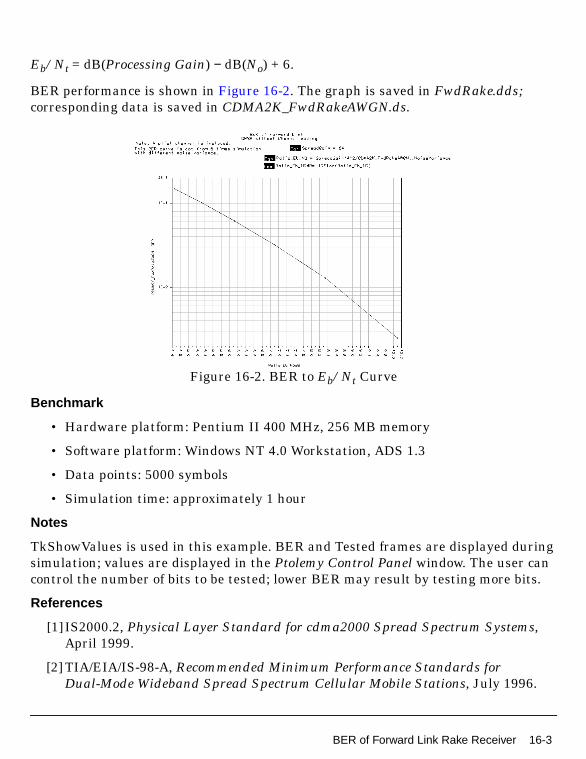
Eb/Nt = dB(Processing Gain) − dB(No) + 6.
BER performance is shown in Figure 16-2. The graph is saved in FwdRake.dds;corresponding data is saved in CDMA2K_FwdRakeAWGN.ds.
Figure 16-2. BER to Eb/Nt Curve
Benchmark
• Hardware platform: Pentium II 400 MHz, 256 MB memory
• Software platform: Windows NT 4.0 Workstation, ADS 1.3
• Data points: 5000 symbols
• Simulation time: approximately 1 hour
Notes
TkShowValues is used in this example. BER and Tested frames are displayed duringsimulation; values are displayed in the Ptolemy Control Panel window. The user cancontrol the number of bits to be tested; lower BER may result by testing more bits.
References
[1] IS2000.2, Physical Layer Standard for cdma2000 Spread Spectrum Systems,April 1999.
[2] TIA/EIA/IS-98-A, Recommended Minimum Performance Standards forDual-Mode Wideband Spread Spectrum Cellular Mobile Stations, July 1996.
BER of Forward Link Rake Receiver 16-3
Rake Design Examples
BER of Reverse Link Rake Receiver• DsnCDMA2K_RevRake.dsn
Features
• HPSK modulation
• 1.2288 Mcps chip rate
• AWGN and fading channel
• Rake receiver for reverse traffic channel
• BER value
• Performance curve
Description
DsnCDMA2K_RevRake.dsn is an example design for measuring reverse link Rakereceiver BER performance.
Schematic
The schematic for this design is shown in Figure 16-3.
16-4 BER of Reverse Link Rake Receiver

Figure 16-3. DsnCDMA2K_RevRake.dsn
Specific parameter settings are:
• WalshLength (CDMA2K_WalshModulator): 16
• WalshCodeIndex (CDMA2K_WalshModulator): 6
• SpreadRate (CDMA2K_BaseFilter, CDMA2K_RevChnlEstimate,CDMA2K_RevCohReceiver): SR1
• FingerNum (CDMA2K_RevChnlEstimate, CDMA2K_RevCohReceiver):3 (Multipath fading channel), 1 (AWGN only)
Simulation Results
Note that noise is band limited, and its bandwidth is 4 times the bandwidth of thebaseband filter. When Eb/Nt is calculated, only the inband noise power is considered.For example, if the noise power (2*variance) is set as 100, then the inband noisepower is set as 25, the real noise power equals the measured noise power PN − 6dB.
BER of Reverse Link Rake Receiver 16-5
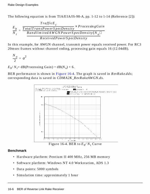
Rake Design Examples
The following equation is from TIA/EIA/IS-98-A, pp. 1-12 to 1-14 (Reference [2]):
In this example, for AWGN channel, transmit power equals received power. For RC320msec frames without channel coding, processing gain equals 16 (12.04dB).
Eb/Nt= dB(Processing Gain) − dB(No) + 6.
BER performance is shown in Figure 16-4. The graph is saved in RevRake.dds;corresponding data is saved in CDMA2K_RevRakeAWGN.ds.
Figure 16-4. BER to Eb/Nt Curve
Benchmark
• Hardware platform: Pentium II 400 MHz, 256 MB memory
• Software platform: Windows NT 4.0 Workstation, ADS 1.3
• Data points: 5000 symbols
• Simulation time: approximately 1 hour
EbNt-------
TrafficEcTotalTransPowerSpecDensity------------------------------------------------------------------------------------------ Proces gGainsin×
BandlimitedAWGNPowerSpecDensity No( )ReceivedPowerSpecDensity
---------------------------------------------------------------------------------------------------------------------------------
------------------------------------------------------------------------------------------------------------------------------------------------=
No2
-------- σ2=
16-6 BER of Reverse Link Rake Receiver

Notes
TkShowValues is used in this example. BER and Tested frames are displayed duringsimulation; values are displayed in the Ptolemy Control Panel window. The user cancontrol the number of bits to be tested; lower BER may result by testing more bits.
References
[1] IS2000.2, Physical Layer Standard for cdma2000 Spread Spectrum Systems,April 1999.
[2] TIA/EIA/IS-98-A, Recommended Minimum Performance Standards forDual-Mode Wideband Spread Spectrum Cellular Mobile Stations, July 1996.
BER of Reverse Link Rake Receiver 16-7

Rake Design Examples
16-8 BER of Reverse Link Rake Receiver

Chapter 17: Signal Source Design Examples
IntroductionThe SignalSource_prj project shows cdma2000 signal source measurementcharacteristics, including transmit power spectrum and the waveform quality of theforward pilot source, transmit power spectrum and CCDF of the forward source,transmit power spectrum, rho and CCDF of the reverse source. Designs for thesemeasurements include:
• BS_PilotSrc.dsn for the measurement of transmit power spectrum andwaveform quality of the forward pilot source
• BS_SR1Src.dsn for the measurement of transmit power spectrum and CCDF ofthe forward source
• MS_SR1Src.dsn for the measurement of transmit power spectrum, rho andCCDF of the reverse source
Transmit Power Spectrum and Waveform Quality ofForward Pilot Source
• BS_PilotSrc.dsn
Features
• Forward pilot channel
• Eye diagram and constellation display during simulation
• Transmit spectrum and waveform quality measurements
Description
This example measures the transmit power spectrum and waveform quality of theforward pilot source. The eye diagram and constellations are displayed duringsimulation.
Introduction 17-1

Signal Source Design Examples
Schematic
Figure 17-1. BS_PilotSrc.dsn Schematic
Simulation Results
Simulation results displayed in BS_PilotSrc.dds are shown in Figure 17-2.
17-2 Transmit Power Spectrum and Waveform Quality of Forward Pilot Source
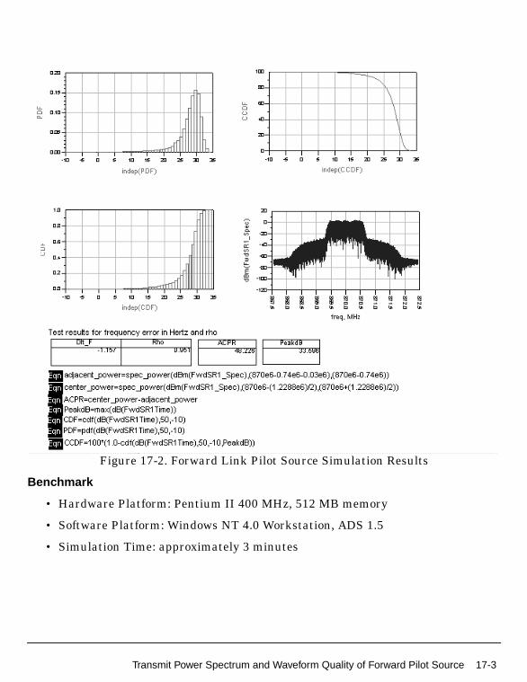
Figure 17-2. Forward Link Pilot Source Simulation Results
Benchmark
• Hardware Platform: Pentium II 400 MHz, 512 MB memory
• Software Platform: Windows NT 4.0 Workstation, ADS 1.5
• Simulation Time: approximately 3 minutes
Transmit Power Spectrum and Waveform Quality of Forward Pilot Source 17-3
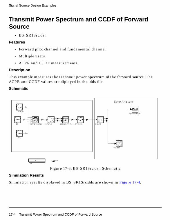
Signal Source Design Examples
Transmit Power Spectrum and CCDF of ForwardSource
• BS_SR1Src.dsn
Features
• Forward pilot channel and fundamental channel
• Multiple users
• ACPR and CCDF measurements
Description
This example measures the transmit power spectrum of the forward source. TheACPR and CCDF values are diplayed in the .dds file.
Schematic
Figure 17-3. BS_SR1Src.dsn Schematic
Simulation Results
Simulation results displayed in BS_SR1Src.dds are shown in Figure 17-4.
17-4 Transmit Power Spectrum and CCDF of Forward Source
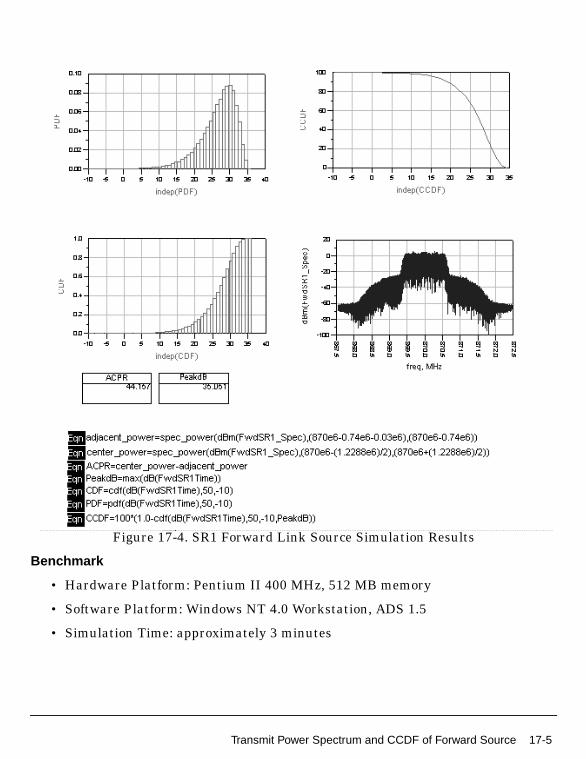
Figure 17-4. SR1 Forward Link Source Simulation Results
Benchmark
• Hardware Platform: Pentium II 400 MHz, 512 MB memory
• Software Platform: Windows NT 4.0 Workstation, ADS 1.5
• Simulation Time: approximately 3 minutes
Transmit Power Spectrum and CCDF of Forward Source 17-5
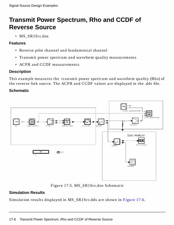
Signal Source Design Examples
Transmit Power Spectrum, Rho and CCDF ofReverse Source
• MS_SR1Src.dsn
Features
• Reverse pilot channel and fundamental channel
• Transmit power spectrum and waveform quality measurements
• ACPR and CCDF measurements
Description
This example measures the transmit power spectrum and waveform quality (Rho) ofthe reverse link source. The ACPR and CCDF values are displayed in the .dds file.
Schematic
Figure 17-5. MS_SR1Src.dsn Schematic
Simulation Results
Simulation results displayed in MS_SR1Src.dds are shown in Figure 17-6.
17-6 Transmit Power Spectrum, Rho and CCDF of Reverse Source
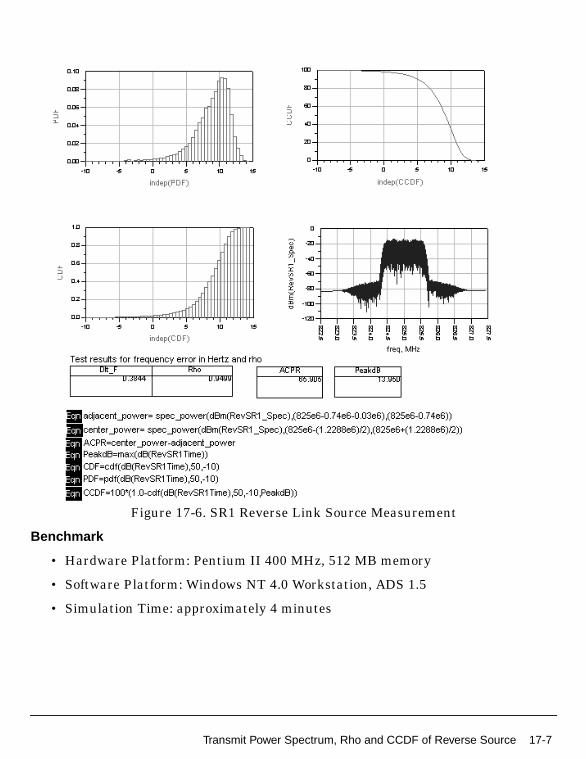
Figure 17-6. SR1 Reverse Link Source Measurement
Benchmark
• Hardware Platform: Pentium II 400 MHz, 512 MB memory
• Software Platform: Windows NT 4.0 Workstation, ADS 1.5
• Simulation Time: approximately 4 minutes
Transmit Power Spectrum, Rho and CCDF of Reverse Source 17-7
Signal Source Design Examples
17-8 Transmit Power Spectrum, Rho and CCDF of Reverse Source

Chapter 18: TPC Design Examples
IntroductionThe CDMA2K_TPC_prj project shows examples for measuring forward and reverselink transmission power. The following sections describe the designs and provideschematics and simulation results.
Power Control of Forward Link Radio Configuration3
• DsnCDMA2K_FwdPC.dsn
Features
• Constant data rate 9600 bps
• Convolutional encoder and Viterbi decoder
• QPSK modulation
• 1.2288 Mcps chip rate
• Multipath fading channel
• Rake receiver for forward traffic channel
• Power control for forward traffic channel
• BER and FER values
• Performance curve
Description
DsnCDMA2K_FwdPC.dsn is an example designed for measuring BER and FERperformance of forward link RC3 in a multipath fading channel.
Schematic
The schematic for this design is shown in Figure 18-1.
Introduction 18-1

TPC Design Examples
Figure 18-1. DsnCDMA2K_FwdPC.dsn
Subnetworks FwdPC_ChannelCoding.dsn and FwdPC_ChannelDecoding.dsn weredesigned for use in this example.
• FwdPC_ChannelCoding.dsn: channel coding includes CRC encoder, add tail,convolutional encoder and interleaver.
Specific parameter settings for this subnetwork are
• InputFrameLen (CDMA2K_CRC_Coder): 172
• CRCType (CDMA2K_CRC_Coder): CRC12 0x1f13
• CCType (CDMA2K_CC_WithTail): rate 1/4 K 9 g0 0765 g1 0671 g2 0513 g3 0473
• BlockRow_m and BlockColumn_J (CDMA2K_BlockIntlvr): m=6, J=12
• IntlvrType (CDMA2K_BlockIntlvr): Fwd_Backwards
• FwdPC_ChannelDeCoding.dsn: channel decoding includes de-interleaver,Viterbi decoder, CRC check and erasing tail.
Specific parameter settings for this subnetwork are
• InputFrameLen (CDMA2K_CRC_DeCoder): 184
18-2 Power Control of Forward Link Radio Configuration 3

• CRCType (CDMA2K_CRC_DeCoder): CRC12 0x1f13
• CCType (CDMA2K_DCC_WithTail): rate 1/4 K 9 g0 0765 g1 0671 g2 0513 g30473
• BlockRow_m and BlockColumn_J (CDMA2K_BlockDeIntlvr): m=6, J=12
• IntlvrType (CDMA2K_BlockDeIntlvr): Fwd_Backwards
Simulation Conditions
• Multipath fading channel: no pathloss, three path
• Gaussian noise variance: 5
• Active user number: 30
• Power-controlled user number: 1
• Power adjustment step: 1 dB
• SIR threshold in receiver is 0 dB
• FER threshold is 0.007
Simulation Results
The output power is shown in Figure 18-2. The graph is saved in FwdPC.dds;corresponding data is saved in FwdPC.ds.
The BER and FER are shown in Figure 18-3. The graph is saved in FwdPC.dds;corresponding data is saved in FwdPC.ds.
Figure 18-2. Power Control and Average Power
Power Control of Forward Link Radio Configuration 3 18-3
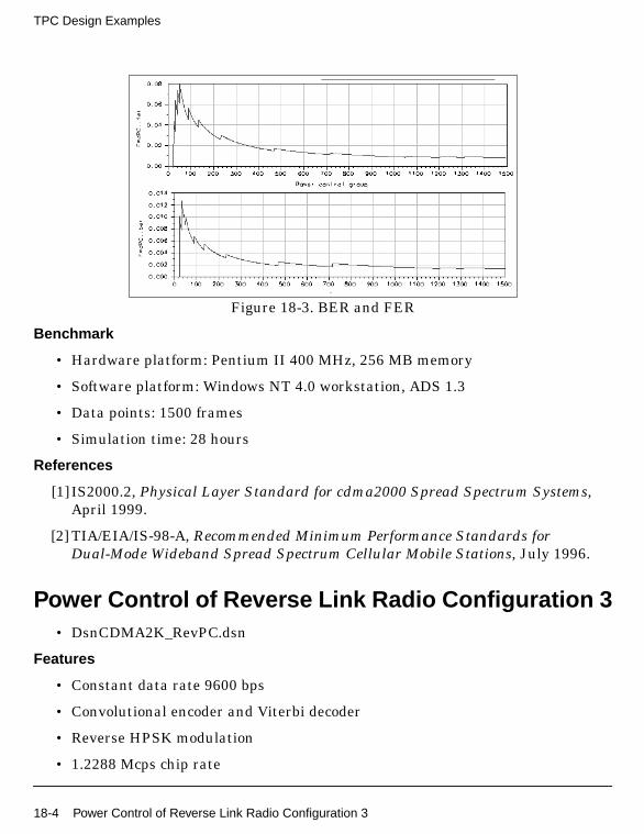
TPC Design Examples
Figure 18-3. BER and FER
Benchmark
• Hardware platform: Pentium II 400 MHz, 256 MB memory
• Software platform: Windows NT 4.0 workstation, ADS 1.3
• Data points: 1500 frames
• Simulation time: 28 hours
References
[1] IS2000.2, Physical Layer Standard for cdma2000 Spread Spectrum Systems,April 1999.
[2] TIA/EIA/IS-98-A, Recommended Minimum Performance Standards forDual-Mode Wideband Spread Spectrum Cellular Mobile Stations, July 1996.
Power Control of Reverse Link Radio Configuration 3• DsnCDMA2K_RevPC.dsn
Features
• Constant data rate 9600 bps
• Convolutional encoder and Viterbi decoder
• Reverse HPSK modulation
• 1.2288 Mcps chip rate
18-4 Power Control of Reverse Link Radio Configuration 3

• Multipath fading channel
• Rake receiver for reverse traffic channel
• Power control for reverse traffic channel
• BER and FER values
• Performance curve
Description
DsnCDMA2K_RevPC.dsn is a design example for measuring BER and FERperformance under power control of reverse link RC3 in a multipath fading channel.
Schematic
The schematic for this design is shown in Figure 18-4.
Figure 18-4. DsnCDMA2K_RevPC.dsn
Subnetworks RevPC_ChannelCoding.dsn, RevPC_Receiver.dsn andRevPC_ChannelDecoding.dsn were designed for use in this example.
• RevPC_ChannelCoding.dsn: channel coding includes CRC encoder, adding tail,convolutional encoder and interleaver.
Specific parameter settings for this subnetwork are
• InputFrameLen (CDMA2K_CRC_Coder): 172
Power Control of Reverse Link Radio Configuration 3 18-5
TPC Design Examples
• CRCType (CDMA2K_CRC_Coder): CRC12 0x1f13
• CCType (CDMA2K_CC_WithTail): rate 1/4 K 9 g0 0765 g1 0671 g2 0513 g3 0473
• BlockRow_m and BlockColumn_J: (CDMA2K_BlockIntlvr): m=6, J=24
• IntlvrType: (CDMA2K_BlockIntlvr): BroIntlvr
• RevPC_ChannelDeCoding.dsn: channel decoding includes de-interleaver,Viterbi decoder, CRC check and erasing tail.
Specific parameter settings for this subnetwork are
• InputFrameLen (CDMA2K_CRC_DeCoder): 184
• CRCType (CDMA2K_CRC_DeCoder): CRC12 0x1f13
• CCType (CDMA2K_DCC_WithTail): rate 1/4 K 9 g0 0765 g1 0671 g2 0513 g30473
• BlockRow_m and BlockColumn_J: (CDMA2K_BlockDeIntlvr): m=6, J=24
• IntlvrType: (CDMA2K_BlockDeIntlvr): BroIntlvr
Simulation Conditions
• Multipath fading channel: no pathloss, three path
• Gaussian noise variance: 200
• Power adjustment step: 1dB
• SIR threshold in receiver is 0dB
• FER threshold is 0.007
Simulation Results
Output power is shown in Figure 18-5. The graph is saved in RevPC.dds;corresponding data is saved in RevPC.ds.
BER and FER are shown in Figure 18-6. The graph is saved in RevPC.dds;corresponding data is saved in RevPC.ds.
18-6 Power Control of Reverse Link Radio Configuration 3
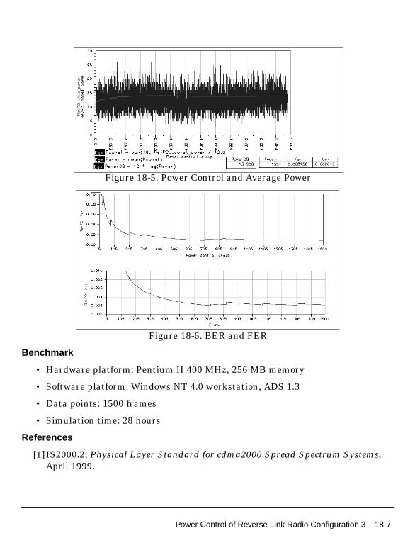
Figure 18-5. Power Control and Average Power
Figure 18-6. BER and FER
Benchmark
• Hardware platform: Pentium II 400 MHz, 256 MB memory
• Software platform: Windows NT 4.0 workstation, ADS 1.3
• Data points: 1500 frames
• Simulation time: 28 hours
References
[1] IS2000.2, Physical Layer Standard for cdma2000 Spread Spectrum Systems,April 1999.
Power Control of Reverse Link Radio Configuration 3 18-7

TPC Design Examples
[2] TIA/EIA/IS-98-A, Recommended Minimum Performance Standards forDual-Mode Wideband Spread Spectrum Cellular Mobile Stations, July 1996.
18-8 Power Control of Reverse Link Radio Configuration 3

Chapter 19: Turbo Code Design Examples
IntroductionThe CDMA2K_TurboCode_prj shows examples for measuring turbo decoder BERperformance. The following sections describe the designs and provide schematics andsimulation results.
BER of Turbo Decoder (MAP)• DsnCDMA2K_TurboCode.dsn
Features
• MAP algorithm
• 3-level MAP decoder
• BER curve
• Comparison of performance with and without turbo coder
Description
The Monte Carlo method is used to estimate the BER performance of the turbo codein AWGN channel. The BER performance without channel coding is measured andcompared during the same simulation.
Schematic
Introduction 19-1
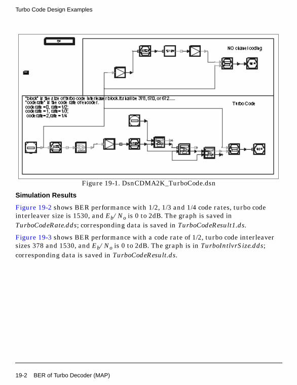
Turbo Code Design Examples
Figure 19-1. DsnCDMA2K_TurboCode.dsn
Simulation Results
Figure 19-2 shows BER performance with 1/2, 1/3 and 1/4 code rates, turbo codeinterleaver size is 1530, and Eb/No is 0 to 2dB. The graph is saved inTurboCodeRate.dds; corresponding data is saved in TurboCodeResult1.ds.
Figure 19-3 shows BER performance with a code rate of 1/2, turbo code interleaversizes 378 and 1530, and Eb/No is 0 to 2dB. The graph is in TurboIntlvrSize.dds;corresponding data is saved in TurboCodeResult.ds.
19-2 BER of Turbo Decoder (MAP)

Figure 19-2. BER Performance withDifferent Code Rates, Interleaver size of 1530
Figure 19-3. BER Performance with Code Rate of 1/2,Interleaver Sizes 378 and 1530
Benchmark
• Hardware platform: Pentium II 400 MHz, 256 MB memory
• Software platform: Windows NT 4.0 Workstation, ADS 1.3
• Data points: 100,000 frames
• Simulation time: approximately 10 hours
Notes
BER of Turbo Decoder (MAP) 19-3

Turbo Code Design Examples
The CDMA_AWGN_Ch and CDMA_BER_Sink models are used to obtain BER valuesbased on Eb/No in one simulation. When the Monte Carlo method is used to estimatethe BER, more symbols are used for higher Eb/No than are used for lower Eb/No toget the same reliability. For example, if four values are needed in one curve, to savesimulation time the test can be done in two steps: test for low SNR and test for highSNR.
19-4 BER of Turbo Decoder (MAP)
Index
Ccdma2000-Compliant Design Library, 1-1CDMA2K_BaseFilter, 6-3CDMA2K_BFER, 5-2CDMA2K_BlindCRC, 3-2CDMA2K_BlindDecoder, 3-5CDMA2K_BlindRevRC1_2, 3-8CDMA2K_BlockDeIntlvr, 3-11CDMA2K_BlockIntlvr, 3-13CDMA2K_BSTX, 6-2CDMA2K_CarrierFreqEstimate, 4-2CDMA2K_CC_WithTail, 3-17CDMA2K_CDP, 5-5CDMA2K_ClassicChannel, 2-2CDMA2K_ClassicSpec, 2-5CDMA2K_CoefDownSample, 4-4CDMA2K_CRC_Coder, 3-19CDMA2K_CRC_DeCoder, 3-22CDMA2K_DataScrambling, 6-6CDMA2K_DataScrambling_U, 6-8CDMA2K_DCC_WithTail, 3-25CDMA2K_Delay, 2-7CDMA2K_DePuncture, 3-27CDMA2K_FIR, 6-10CDMA2K_FlatChannel, 2-9CDMA2K_FlatSpec, 2-12CDMA2K_FR_RateDematch, 3-29CDMA2K_FR_RateMatch, 3-31CDMA2K_FwdChannelCoding, 3-33CDMA2K_FwdChannelDecoding, 3-35CDMA2K_FwdChnlEstimate, 4-6CDMA2K_FwdCohReceiver, 4-8CDMA2K_FwdMultiUserSrc, 5-8CDMA2K_FwdOCNS, 5-10CDMA2K_FwdOTDreceiver, 4-10CDMA2K_FwdOTDsrc, 8-2CDMA2K_FwdPCBitExtraction, 6-14CDMA2K_FwdPCBitExtraction_U, 6-16CDMA2K_FwdPCBitPuncture, 6-19CDMA2K_FwdPCBitPuncture_U, 6-21CDMA2K_FwdPilotSrc, 8-4CDMA2K_FwdPowerAllocation, 6-24CDMA2K_FwdPwrAlloc, 6-26CDMA2K_FwdQPSK, 6-29CDMA2K_FwdRake, 4-13CDMA2K_FwdRake_U, 4-15CDMA2K_FwdRCreceiver, 4-17CDMA2K_FwdRCsrc, 8-5CDMA2K_FwdRho, 5-12CDMA2K_FwdSIREstimate, 6-31CDMA2K_FwdSTSreceiver, 4-19CDMA2K_FwdSTSsrc, 8-7CDMA2K_FwdTDpwrAlloc, 6-33CDMA2K_FwdVectorChannel, 2-14CDMA2K_Interpolation, 2-16CDMA2K_LongCodeGenerator, 6-36CDMA2K_MAPDecoder1, 3-37CDMA2K_MAPDecoder2, 3-39CDMA2K_MC_DownConv, 5-14CDMA2K_MC_UpConv, 5-17CDMA2K_MCMode_DeIntlvr, 3-41CDMA2K_MCMode_Intlvr, 3-43CDMA2K_MSTX, 6-38CDMA2K_OneWay, 3-45CDMA2K_OnewayRevRC1_2, 3-47CDMA2K_PCBgenerator, 6-39CDMA2K_PhaseDetector, 4-22CDMA2K_PNCode, 6-41CDMA2K_PNCode_U, 6-42CDMA2K_PowerControl, 6-45CDMA2K_Puncture, 3-49CDMA2K_PwrMeasure, 7-2CDMA2K_QuasiOrthMask, 6-47CDMA2K_QuasiOrthMask_U, 6-48CDMA2K_RevChannelCoding, 3-51CDMA2K_RevChannelDecoding, 3-53CDMA2K_RevChnlEstimate, 4-24CDMA2K_RevCohReceiver, 4-26CDMA2K_RevDeHPSK, 4-28CDMA2K_RevHPSK, 6-50CDMA2K_RevPCBitPuncture, 6-52CDMA2K_RevPowerAdjust, 6-54CDMA2K_RevPowerAllocation, 6-56CDMA2K_RevPowerAllocation_U, 6-58CDMA2K_RevRake, 4-30CDMA2K_RevRCreceiver, 4-32CDMA2K_RevRCsrc, 8-9CDMA2K_RevRhoWithRef, 5-19CDMA2K_RevSIREstimate, 6-65CDMA2K_RevVectorChannel, 2-17
Index-1

CDMA2K_RF_Demod, 7-4CDMA2K_RF_Mod, 7-6CDMA2K_SR3LongCode, 6-67CDMA2K_SymCyclicShift, 3-55CDMA2K_TurboDecoder, 3-57CDMA2K_TurboDeIntlvr, 3-59CDMA2K_TurboDeMux, 3-61CDMA2K_TurboEncoder, 3-63CDMA2K_TurboIntlvr, 3-66CDMA2K_TurboMAPDecoder, 3-70CDMA2K_TurboMux, 3-72CDMA2K_TurboRSCEncoder, 3-75CDMA2K_VL_Walsh, 6-69CDMA2K_VR_AmpAdjust, 3-78CDMA2K_VR_CCwithTail, 3-81CDMA2K_VR_Coding, 3-84CDMA2K_VR_Compare, 3-86CDMA2K_VR_DCCwithTail, 3-88CDMA2K_VR_DeFraming, 3-91CDMA2K_VR_Framing, 3-94CDMA2K_VR_RateDeMatch, 3-97CDMA2K_VR_RateMatch, 3-101CDMA2K_VR_Src, 3-105CDMA2K_WalshModulator, 6-70CDMA2K_WalshRotateFunction, 6-72
Index-2