Embed Size (px)
Citation preview

Cosmic RAy Telescope for the Effects of Radiation
CDR v1Telescope Mechanical Design
Albert Lin
The Aerospace Corporation
Mechanical Engineer
(310) 336-1023
5/1/06
Cosmic RAy Telescope for the Effects of Radiation
Overview
Design Overview
Instrument Requirements
Mechanical Requirements
Design Details
Next Steps
Cosmic RAy Telescope for the Effects of Radiation
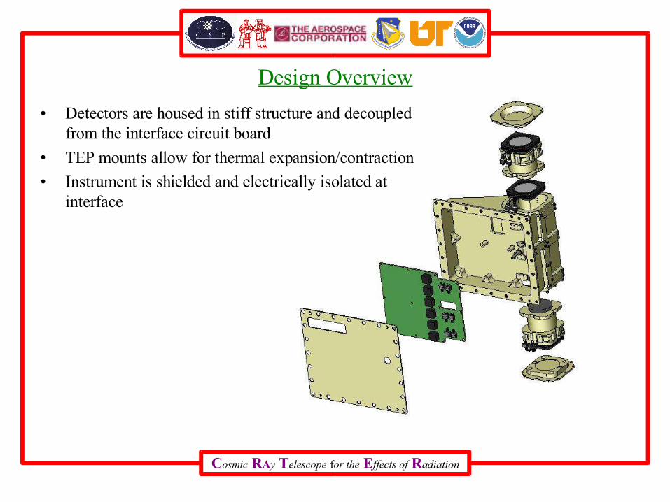
Design Overview
• Detectors are housed in stiff structure and decoupled from the interface circuit board
• TEP mounts allow for thermal expansion/contraction
• Instrument is shielded and electrically isolated at interface

Cosmic RAy Telescope for the Effects of Radiation
Overall Dimensions
• Weight = 2.89 lbsComponent Weight (kg) Weight (lbs)
Structure 0.698 1.540
Circuit Board 0.145 0.320
Telescope 0.467 1.030
Total 1.309 2.890
Cosmic RAy Telescope for the Effects of Radiation
Overview
Design Overview
Instrument Requirements
Mechanical Requirements
Design Details
Next Steps

Cosmic RAy Telescope for the Effects of Radiation
Instrument Requirements
From Instrument Requirements Document (IRD) 32-01205
Zenith field of view from D1D6 at 35 degreesCRaTER-L3-06
TEP components of 27 mm and 54 mm in lengthCRaTER-L2-04
Adjacent pairs of 140 micron and 1000 micron thick Si detectorsCRaTER-L3-01
Nadir field of view from D3D6 at 80 degreesCRaTER-L3-07
Telescope stack: S1, D1, D2, A1, D3, D4, A2, D5, D6, S2CRaTER-L3-04
0.030” thick aluminum on both ends of the telescopeCRaTER-L3-03
Aluminum shielding 0.06” thickCRaTER-L3-02
RequirementItem
All requirements incorporated into model

Cosmic RAy Telescope for the Effects of Radiation
Telescope Geometry
All Requirements Met
A-150 TEP of 27 mm and 54 mm in length
Pairs of thin (~140 micron) and thick (~1000 micron) Si detectors used
0.060” nominal aluminum shielding
0.030” thick aluminum on top and bottom apertures
Telescope stack consistent with requirement
Within 35 degree Field of Regard Zenith
Within 80 degree Field of Regard Nadir
Cosmic RAy Telescope for the Effects of Radiation
Overview
Design Overview
Instrument Requirements
Mechanical Requirements
Design Details
Next Steps
Cosmic RAy Telescope for the Effects of Radiation
Mechanical Requirements
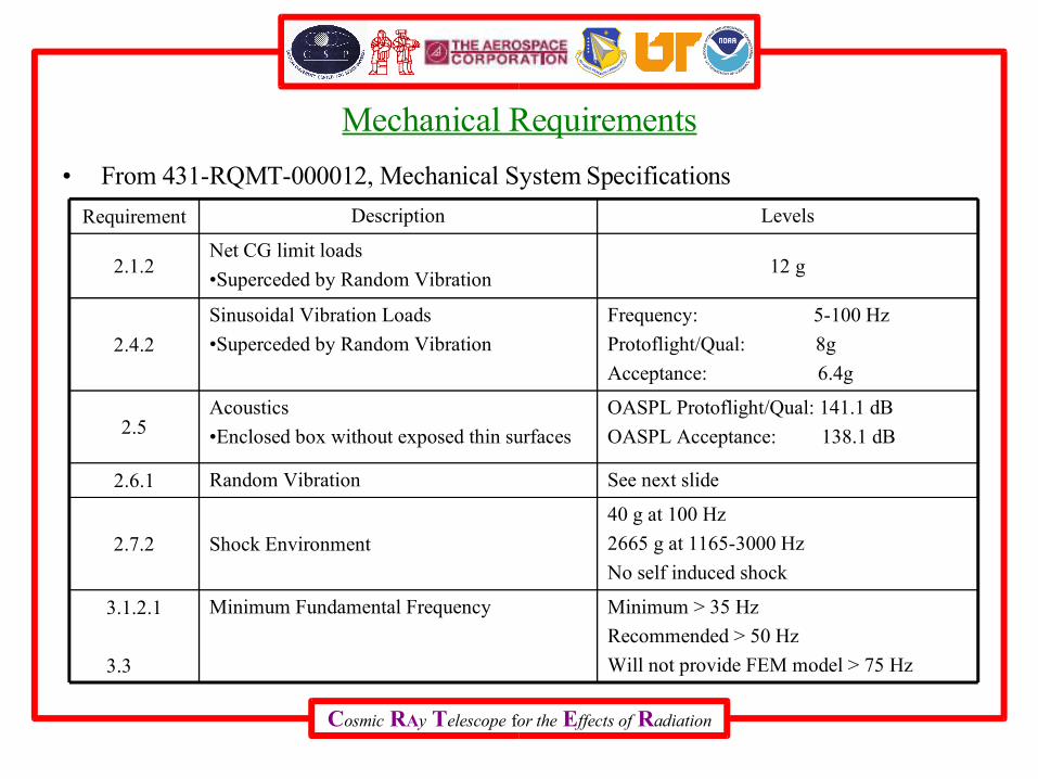
• From 431-RQMT-000012, Mechanical System Specifications
40 g at 100 Hz
2665 g at 1165-3000 Hz
No self induced shock
Shock Environment2.7.2
Minimum > 35 Hz
Recommended > 50 Hz
Will not provide FEM model > 75 Hz
Minimum Fundamental Frequency3.1.2.1
3.3
See next slideRandom Vibration2.6.1
OASPL Protoflight/Qual: 141.1 dB
OASPL Acceptance: 138.1 dB
Acoustics
•Enclosed box without exposed thin surfaces2.5
Frequency: 5-100 Hz
Protoflight/Qual: 8g
Acceptance: 6.4g
Sinusoidal Vibration Loads
•Superceded by Random Vibration2.4.2
12 gNet CG limit loads
•Superceded by Random Vibration2.1.2
LevelsDescriptionRequirement

Cosmic RAy Telescope for the Effects of Radiation
Random Vibration
• Random Vibration will drive most of the analysis
• For resonances in the Random Vibration Spec, Miles’ Equation shows 3 sigma loading on the order of 150-200 g
• Assume Q = 20
Random Vibration Spec
0.01
0.1
1
1 10 100 1000 10000
Frequency (Hz)
Po
wer
Sp
ectr
al D
ensi
ty (
g^2
/Hz)
Protoflight/ Qual
Acceptance
Freq (Hz )
P rotoflight / Qual A c ceptance
20 0.026 0.01350 0.16 0.08
800 0.16 0.082000 0.026 0.013
Cosmic RAy Telescope for the Effects of Radiation
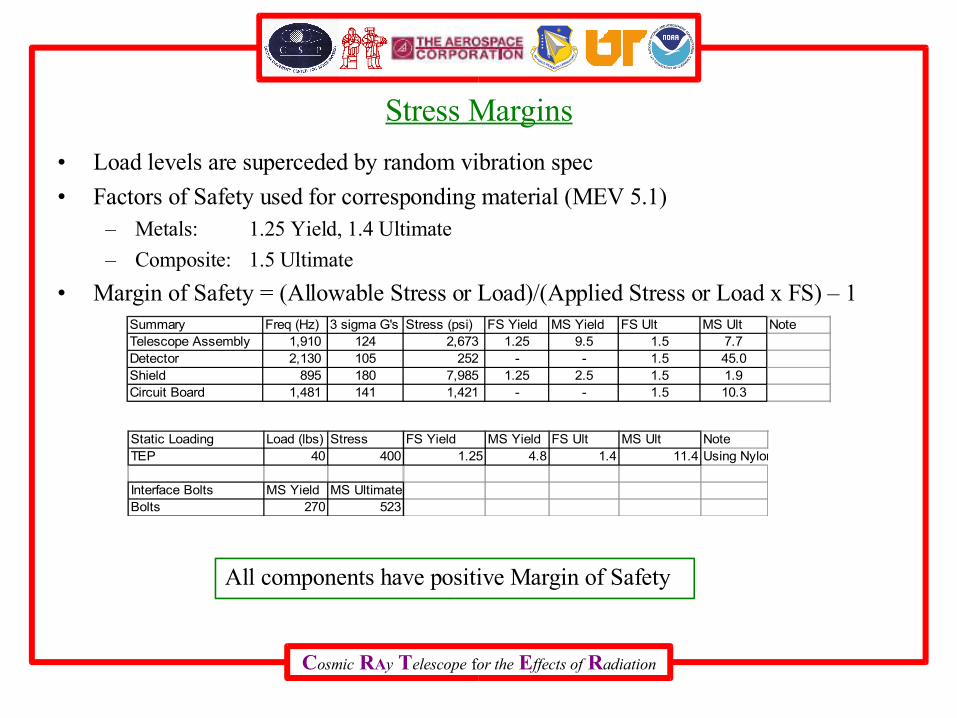
Stress Margins
• Load levels are superceded by random vibration spec
• Factors of Safety used for corresponding material (MEV 5.1)– Metals: 1.25 Yield, 1.4 Ultimate
– Composite: 1.5 Ultimate
• Margin of Safety = (Allowable Stress or Load)/(Applied Stress or Load x FS) – 1
All components have positive Margin of Safety
Summary Freq (Hz) 3 sigma G's Stress (psi) FS Yield MS Yield FS Ult MS Ult NoteTelescope Assembly 1,910 124 2,673 1.25 9.5 1.5 7.7Detector 2,130 105 252 - - 1.5 45.0Shield 895 180 7,985 1.25 2.5 1.5 1.9Circuit Board 1,481 141 1,421 - - 1.5 10.3
Static Loading Load (lbs) Stress FS Yield MS Yield FS Ult MS Ult NoteTEP 40 400 1.25 4.8 1.4 11.4 Using Nylon material properties
Interface Bolts MS Yield MS UltimateBolts 270 523

Cosmic RAy Telescope for the Effects of Radiation
First Fundamental Frequency
• First Fundamental Frequency at 1910 Hz
Cosmic RAy Telescope for the Effects of Radiation
Overview
Design Overview
Instrument Requirements
Mechanical Requirements
Design Details
Next Steps
Cosmic RAy Telescope for the Effects of Radiation
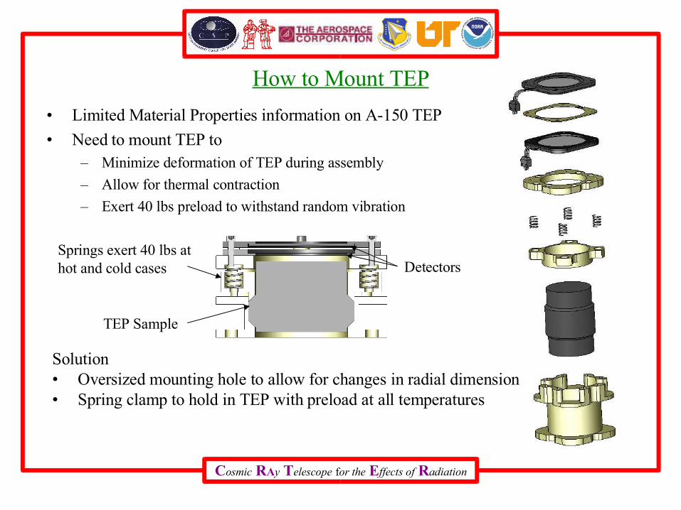
How to Mount TEP
• Limited Material Properties information on A-150 TEP
• Need to mount TEP to– Minimize deformation of TEP during assembly
– Allow for thermal contraction
– Exert 40 lbs preload to withstand random vibration
Springs exert 40 lbs at hot and cold cases Detectors
TEP Sample
Solution• Oversized mounting hole to allow for changes in radial dimension• Spring clamp to hold in TEP with preload at all temperatures

Cosmic RAy Telescope for the Effects of Radiation
Purging and Venting
• Spacers between each pair of detectors for venting
• No enclosed cavities
• Purge/vent system shown in red
• Internal purge line from Ebox connects to telescope purge system
Cosmic RAy Telescope for the Effects of Radiation
Overview
Design Overview
Telescope Requirements
Mechanical Requirements
Design Details
Next Steps

Cosmic RAy Telescope for the Effects of Radiation
Next Steps
• Measure material properties for TEP
• Spring analysis

Cosmic RAy Telescope for the Effects of Radiation
Telescope – Mechanical
Albert Lin
Cosmic RAy Telescope for the Effects of Radiation
Backup Slides

Cosmic RAy Telescope for the Effects of Radiation
CRaTER-L2-04
• 4.4.1 RequirementBreak the TEP into two components, of 27 mm and 54 mm in length.
Cosmic RAy Telescope for the Effects of Radiation
6.1 CRaTER-L3-01Thin and thick detector pairs
• 6.1.1 RequirementThe telescope stack will contain adjacent pairs of thin (approximately 140 micron) and thick
(approximately 1000 micron) Si detectors. The thick detectors will be used to characterize energy deposition between approximately 200 keV and 100 MeV. The thin detectors will be used to characterize energy deposits between 2 MeV and 1 GeV.
6.2 CRaTER-L3-02 Nominal instrument shielding
• 6.2.1 RequirementThe shielding due to mechanical housing the CRaTER telescope outside of the zenith and nadir
fields of view shall be no less than 0.06” of aluminum.

Cosmic RAy Telescope for the Effects of Radiation
6.3 CRaTER-L3-03 Nadir and zenith field of view shielding
• 6.3.1 RequirementThe zenith and nadir sides of the telescope shall have no less than 0.03” of aluminum shielding.
6.4 CRaTER-L3-04 Telescope stack
• 6.4.1 RequirementThe telescope will consist of a stack of components labeled from the nadir side as zenith shield
(S1), the first pair of thin (D1) and thick (D2) detectors, the first TEP absorber (A1), the second pair of thin (D3) and thick (D4) detectors, the second TEP absorber (A2), the third pair of thin (D5) and thick (D6) detectors, and the final nadir shield (S2).

Cosmic RAy Telescope for the Effects of Radiation
6.6 CRaTER-L3-06 Zenith field of view
• 6.6.1 RequirementThe zenith field of view, defined as D1D6 coincident events incident from deep space, will be 35
degrees full width.
6.7 CRaTER-L3-07 Nadir field of view
• 6.7.1 RequirementThe nadir field of view, defined as D3D6 coincident events incident from the lunar surface, will be
75 degrees full width.

Cosmic RAy Telescope for the Effects of Radiation
Bolt Interface Loading
Mechanical Engineering Design, by Shigley
RP-1228 NASA Fastener Design
First fundamental frequency at 1910 Hz
3 sigma load = 124g
A286 CRES #6-32 Bolts at Interface
Inputs Outputs358 lb 24358 lb 34.83 lb358 lb 29.83 lb
1.682 in 270 773 lb 523
1181 lb464 lb
Tensile Yield
Shear YieldTensile Ultimate
Margin of Safety Ult
Normal Load Worst Case BoltIn-Plane Load X Normal LoadIn-Plane Load Y Shear LoadIn-Plane Load Offset Margin of Safety Yield
Cosmic RAy Telescope for the Effects of Radiation
Detector Board Stress
• See Cosmosworks report
Cosmic RAy Telescope for the Effects of Radiation
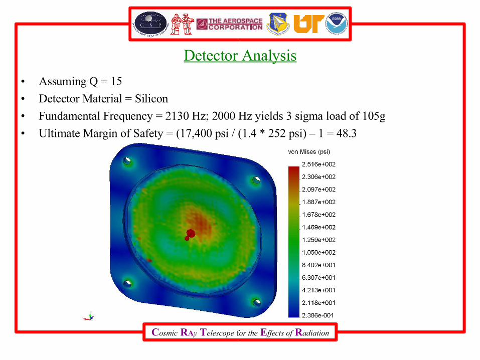
Detector Analysis
• Assuming Q = 15
• Detector Material = Silicon
• Fundamental Frequency = 2130 Hz; 2000 Hz yields 3 sigma load of 105g
• Ultimate Margin of Safety = (17,400 psi / (1.4 * 252 psi) – 1 = 48.3
Cosmic RAy Telescope for the Effects of Radiation
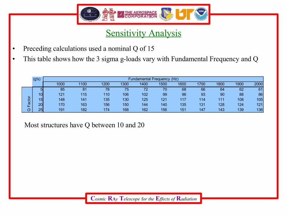
Sensitivity Analysis
• Preceding calculations used a nominal Q of 15
• This table shows how the 3 sigma g-loads vary with Fundamental Frequency and Q
(g's)1000 1100 1200 1300 1400 1500 1600 1700 1800 1900 2000
5 85 81 78 75 72 70 68 66 64 62 6110 121 115 110 106 102 99 96 93 90 88 8615 148 141 135 130 125 121 117 114 111 108 10520 170 163 156 150 144 140 135 131 128 124 12125 191 182 174 168 162 156 151 147 143 139 136
Fundamental Frequency (Hz)
Q F
acto
r
Most structures have Q between 10 and 20
Cosmic RAy Telescope for the Effects of Radiation
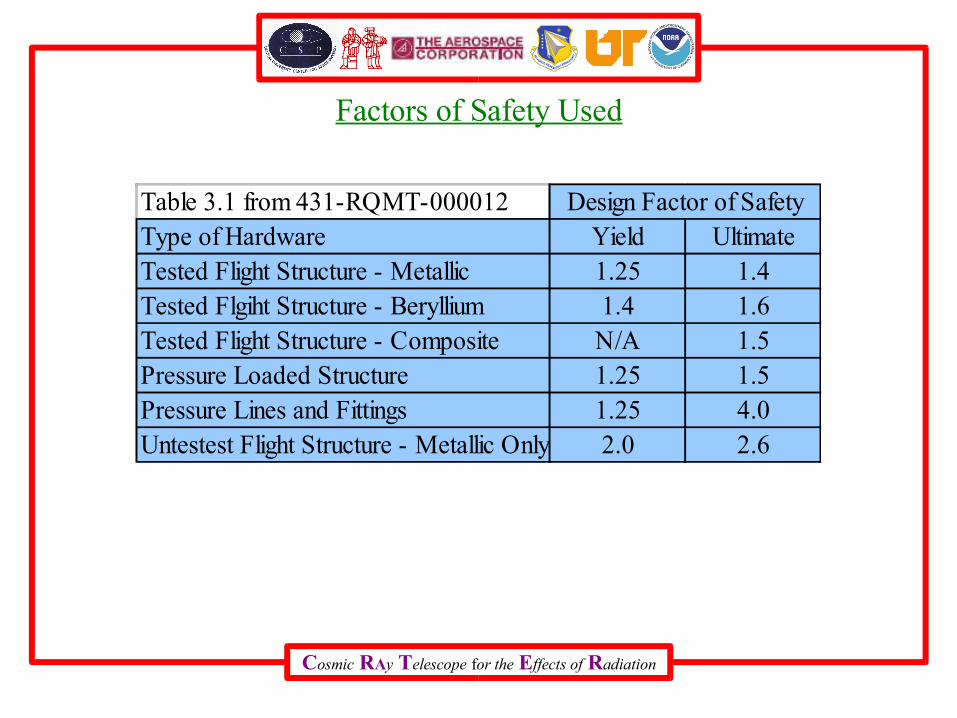
Factors of Safety Used
Table 3.1 from 431-RQMT-000012Type of Hardware Yield UltimateTested Flight Structure - Metallic 1.25 1.4Tested Flgiht Structure - Beryllium 1.4 1.6Tested Flight Structure - Composite N/A 1.5Pressure Loaded Structure 1.25 1.5Pressure Lines and Fittings 1.25 4.0Untestest Flight Structure - Metallic Only 2.0 2.6
Design Factor of Safety
Cosmic RAy Telescope for the Effects of Radiation
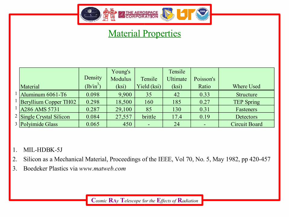
Material Properties
1. MIL-HDBK-5J
2. Silicon as a Mechanical Material, Proceedings of the IEEE, Vol 70, No. 5, May 1982, pp 420-457
3. Boedeker Plastics via www.matweb.com
Material
Density
(lb/in3)
Young's Modulus
(ksi)Tensile
Yield (ksi)
Tensile Ultimate
(ksi)Poisson's
Ratio Where Used
Aluminum 6061-T6 0.098 9,900 35 42 0.33 StructureBeryllium Copper TH02 0.298 18,500 160 185 0.27 TEP SpringA286 AMS 5731 0.287 29,100 85 130 0.31 FastenersSingle Crystal Silicon 0.084 27,557 brittle 17.4 0.19 DetectorsPolyimide Glass 0.065 450 - 24 - Circuit Board
1
1
1
2
3


![Wide Field Infrared Survey Telescope [WFIRST]: Telescope ... · the telescope exit pupil, which acts as the thermal/mechanical/optical interface between the telescope and imaging](https://img.pdfslide.net/doc/110x75/5f7661f13e5d4129fe68e696/wide-field-infrared-survey-telescope-wfirst-telescope-the-telescope-exit.jpg)