Embed Size (px)
Citation preview
CDU-250 User’s Guide DOC0102
Applies to:
CDP-250C Mod-A, Mod-NONE, FW Rev 1.01 and above CDP-250G Mod-A, Mod-NONE, FW Rev 1.01 and above
DVI-250x Mod-A , FW Rev 2.00 and above
DVI-250xP Mod-A , FW Rev 2.00 and above
Document Revision: 01.007
April 15, 2008
SkyTrac Systems Ltd. 200-170 Rutland Road Kelowna, BC Canada Tel. +1 250 765-2393 Fax +1 250 765-3767
Web: www.skytrac.ca Email: [email protected]
Copyright © 2008 SkyTrac Systems Ltd. All rights reserved.
SkyTrac Systems Ltd.
Document Rev. 01.007 DOC0102 Page 2 of 23
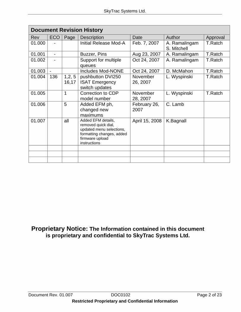
Document Revision History Rev ECO Page Description Date Author Approval 01.000 - Initial Release Mod-A Feb. 7, 2007 A. Ramalingam
S. Mitchell T.Ratch
01.001 - Buzzer, Pins Aug 23, 2007 A. Ramalingam T.Ratch 01.002 - Support for multiple
queues Oct 24, 2007 A. Ramalingam T.Ratch
01.003 - Includes Mod-NONE Oct 24, 2007 D. McMahon T.Ratch 01.004 136 1,2, 5
16,17 pushbutton DVI250 ISAT Emergency switch updates
November 26, 2007
L. Wyspinski T.Ratch
01.005 1 Correction to CDP model number
November 28, 2007
L. Wyspinski T.Ratch
01.006 5 Added EFM ph, changed new maximums
February 26, 2007
C. Lamb
01.007 all Added EFM details, removed quick dial, updated menu selections, formatting changes, added firmware upload instructions
April 15, 2008 K.Bagnall
Proprietary Notice: The Information contained in this document is proprietary and confidential to SkyTrac Systems Ltd.
Restricted Proprietary and Confidential Information
SkyTrac Systems Ltd.
Document Rev. 01.007 DOC0102 Page 3 of 23 Restricted Proprietary and Confidential Information
Table Of Contents 1 Introduction ................................................................................................................... 5
1.1 Scope ....................................................................................................................... 5 1.2 Terminology ............................................................................................................. 5 1.3 Description ............................................................................................................... 5 1.4 Features ................................................................................................................... 6
1.4.1 Phone ............................................................................................................... 6 1.4.2 Email ................................................................................................................. 6 1.4.3 Additional Features ........................................................................................... 6
1.5 System Requirements .............................................................................................. 7 1.6 Acronyms ................................................................................................................. 7
2 General ........................................................................................................................... 7 2.1 Setup ....................................................................................................................... 7
3 Operation ....................................................................................................................... 7 3.1 Menu Navigation ...................................................................................................... 8
3.1.1 Selection Menu ................................................................................................. 8 3.1.2 Edit Menu .......................................................................................................... 8 3.1.3 Information menu .............................................................................................. 9 3.1.4 Hotkey Support ................................................................................................. 9
4 Menu Items .................................................................................................................. 10 4.1 Quick Mail .............................................................................................................. 10
4.1.1 Creating a Quick Message .............................................................................. 10 4.1.2 Sending a Quick Message .............................................................................. 10 4.1.3 Editable Field Messages (EFM) ...................................................................... 11
4.2 Phone .................................................................................................................... 11 4.2.1 Address Book Dial .......................................................................................... 12 4.2.2 Manual Dial ..................................................................................................... 12 4.2.3 Redial .............................................................................................................. 12 4.2.4 Incoming Call .................................................................................................. 12 4.2.5 Dialling DTMF Tones during a Phone Call ...................................................... 13 4.2.6 Volume Control ............................................................................................... 13
4.3 Email ...................................................................................................................... 13 4.3.1 Inbox ............................................................................................................... 13 4.3.2 Compose ........................................................................................................ 14 4.3.3 Outbox ............................................................................................................ 14 4.3.4 Sentbox ........................................................................................................... 14
4.4 System Menu ......................................................................................................... 14 4.4.1 Address Book Menu ....................................................................................... 14 4.4.2 System Setup Menu ....................................................................................... 14 4.4.3 Brightness Control .......................................................................................... 15 4.4.4 Display Off ...................................................................................................... 17
5 ISAT Emergency Mode ............................................................................................... 17
SkyTrac Systems Ltd.
Document Rev. 01.007 DOC0102 Page 4 of 23 Restricted Proprietary and Confidential Information
6 Access Control ............................................................................................................ 18 6.1 PIN Description ...................................................................................................... 18 6.2 Activating the PIN Feature ..................................................................................... 19 6.3 Entering PINS in CDU ............................................................................................ 19
7 Support for Connecting Multiple Devices ................................................................. 19
8 Installing Firmware ..................................................................................................... 20 8.1 Requirements ......................................................................................................... 20 8.2 Firmware Upgrade Instructions .............................................................................. 20
SkyTrac Systems Ltd.
Document Rev. 01.007 DOC0102 Page 5 of 23
1 INTRODUCTION
1.1 Scope This document provides instructions on the operation of the features of SkyTrac System’s Cockpit Display Unit (CDU-250).
1.2 Terminology The CDU-250 refers to the combined operation of DVI-250 and CDP-250 as a voice and data control interface to the ISAT-100. This User’s Guide refers to this combined mode of operation only. Refer to DVI-250 User’s Guide (DOC0039) for DVI-250 stand-alone operation and CDP-250 Mod-A User’s Guide (DOC0103) for CDP-250 stand-alone operation.
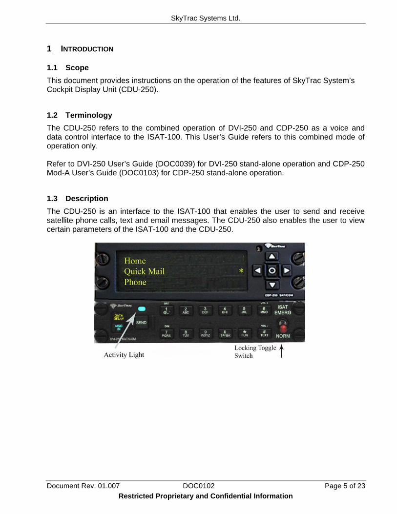
1.3 Description The CDU-250 is an interface to the ISAT-100 that enables the user to send and receive satellite phone calls, text and email messages. The CDU-250 also enables the user to view certain parameters of the ISAT-100 and the CDU-250.
Restricted Proprietary and Confidential Information
SkyTrac Systems Ltd.
Document Rev. 01.007 DOC0102 Page 6 of 23 Restricted Proprietary and Confidential Information
1.4 Features
1.4.1 Phone
International number dialling
Last number redial
Dial from Address Book
9 Address Book entries can be set for Speed Dial
Volume Control (4 settings) 1.4.2 Email
Up to 99 Pre-Programmed Quick Mail Messages
User Programmable Quick Mail Messages
Editable fields in pre-programmed Quick Mail Messages
Complete Email solution to send and receive emails
1.4.3 Additional Features
Address Book (125 entries with phone number and email address)
Emergency switch (push button or toggle) to trigger the ISAT emergency mode.
User configurable Brightness control modes for indicators, display and panel backlights.
View ISAT-100 parameters
View / Configure CDU-250 parameters
Access Control (PIN number option to control SatPhone access)
Self Test Diagnostics
Buzzer Alerts for incoming email and phone calls
SkyTrac Systems Ltd.
Document Rev. 01.007 DOC0102 Page 7 of 23 Restricted Proprietary and Confidential Information
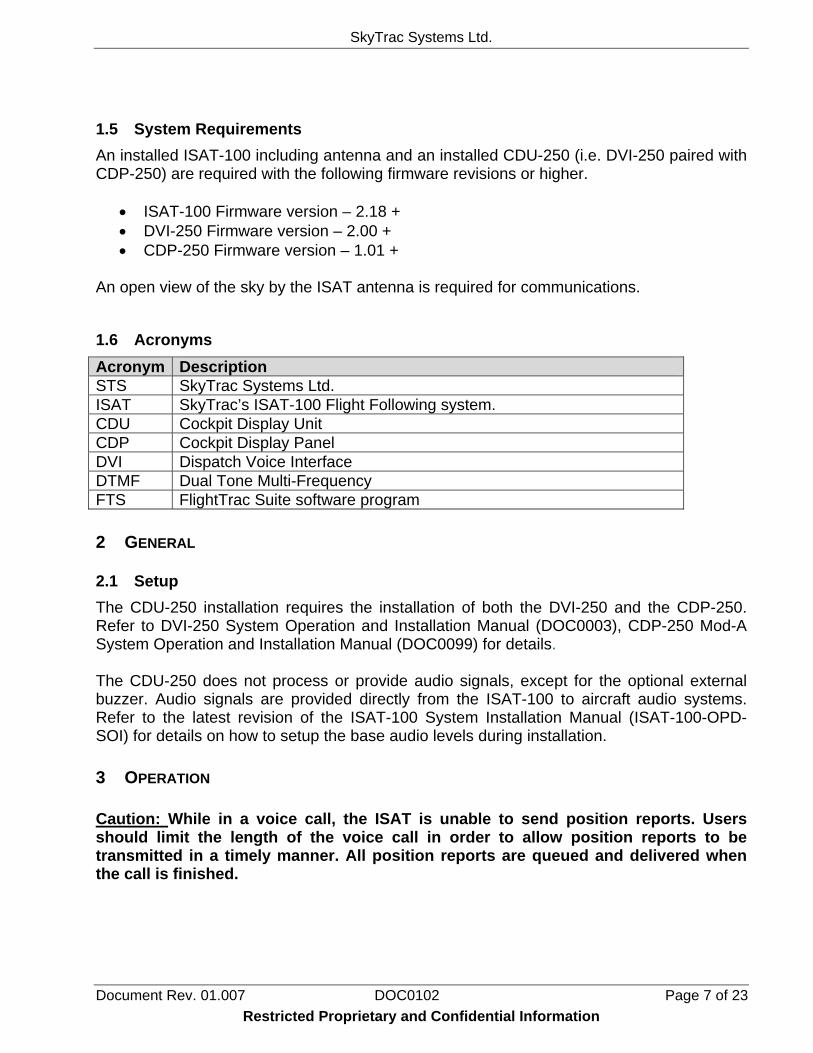
1.5 System Requirements An installed ISAT-100 including antenna and an installed CDU-250 (i.e. DVI-250 paired with CDP-250) are required with the following firmware revisions or higher.
• ISAT-100 Firmware version – 2.18 + • DVI-250 Firmware version – 2.00 + • CDP-250 Firmware version – 1.01 +
An open view of the sky by the ISAT antenna is required for communications.
1.6 Acronyms Acronym Description STS SkyTrac Systems Ltd. ISAT SkyTrac’s ISAT-100 Flight Following system. CDU Cockpit Display Unit CDP Cockpit Display Panel DVI Dispatch Voice Interface DTMF Dual Tone Multi-Frequency FTS FlightTrac Suite software program 2 GENERAL
2.1 Setup The CDU-250 installation requires the installation of both the DVI-250 and the CDP-250. Refer to DVI-250 System Operation and Installation Manual (DOC0003), CDP-250 Mod-A System Operation and Installation Manual (DOC0099) for details. The CDU-250 does not process or provide audio signals, except for the optional external buzzer. Audio signals are provided directly from the ISAT-100 to aircraft audio systems. Refer to the latest revision of the ISAT-100 System Installation Manual (ISAT-100-OPD-SOI) for details on how to setup the base audio levels during installation. 3 OPERATION Caution: While in a voice call, the ISAT is unable to send position reports. Users should limit the length of the voice call in order to allow position reports to be transmitted in a timely manner. All position reports are queued and delivered when the call is finished.
SkyTrac Systems Ltd.
Document Rev. 01.007 DOC0102 Page 8 of 23
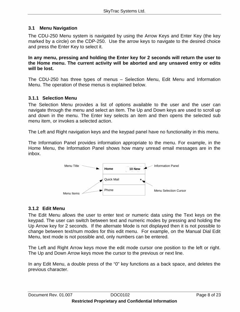
3.1 Menu Navigation The CDU-250 Menu system is navigated by using the Arrow Keys and Enter Key (the key marked by a circle) on the CDP-250. Use the arrow keys to navigate to the desired choice and press the Enter Key to select it. In any menu, pressing and holding the Enter key for 2 seconds will return the user to the Home menu. The current activity will be aborted and any unsaved entry or edits will be lost. The CDU-250 has three types of menus – Selection Menu, Edit Menu and Information Menu. The operation of these menus is explained below. 3.1.1 Selection Menu The Selection Menu provides a list of options available to the user and the user can navigate through the menu and select an item. The Up and Down keys are used to scroll up and down in the menu. The Enter key selects an item and then opens the selected sub menu item, or invokes a selected action. The Left and Right navigation keys and the keypad panel have no functionality in this menu. The Information Panel provides information appropriate to the menu. For example, in the Home Menu, the Information Panel shows how many unread email messages are in the inbox.
Home
Quick Mail
Phone
Menu Title
Menu ItemsMenu Selection Cursor
Information Panel10 New
*
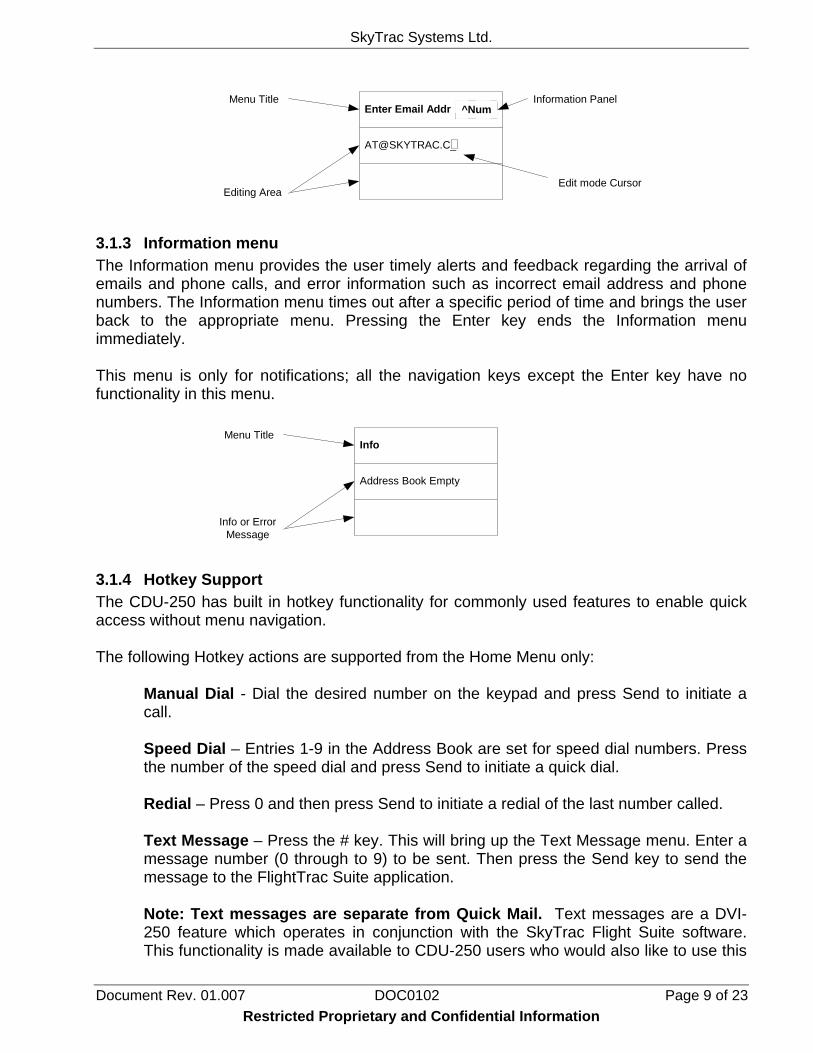
3.1.2 Edit Menu The Edit Menu allows the user to enter text or numeric data using the Text keys on the keypad. The user can switch between text and numeric modes by pressing and holding the Up Arrow key for 2 seconds. If the alternate Mode is not displayed then it is not possible to change between text/num modes for this edit menu. For example, on the Manual Dial Edit Menu, text mode is not possible and, only numbers can be entered. The Left and Right Arrow keys move the edit mode cursor one position to the left or right. The Up and Down Arrow keys move the cursor to the previous or next line. In any Edit Menu, a double press of the “0” key functions as a back space, and deletes the previous character.
Restricted Proprietary and Confidential Information
SkyTrac Systems Ltd.
Document Rev. 01.007 DOC0102 Page 9 of 23
Enter Email Addr ^Num
Menu Title
Editing AreaEdit mode Cursor
Information Panel
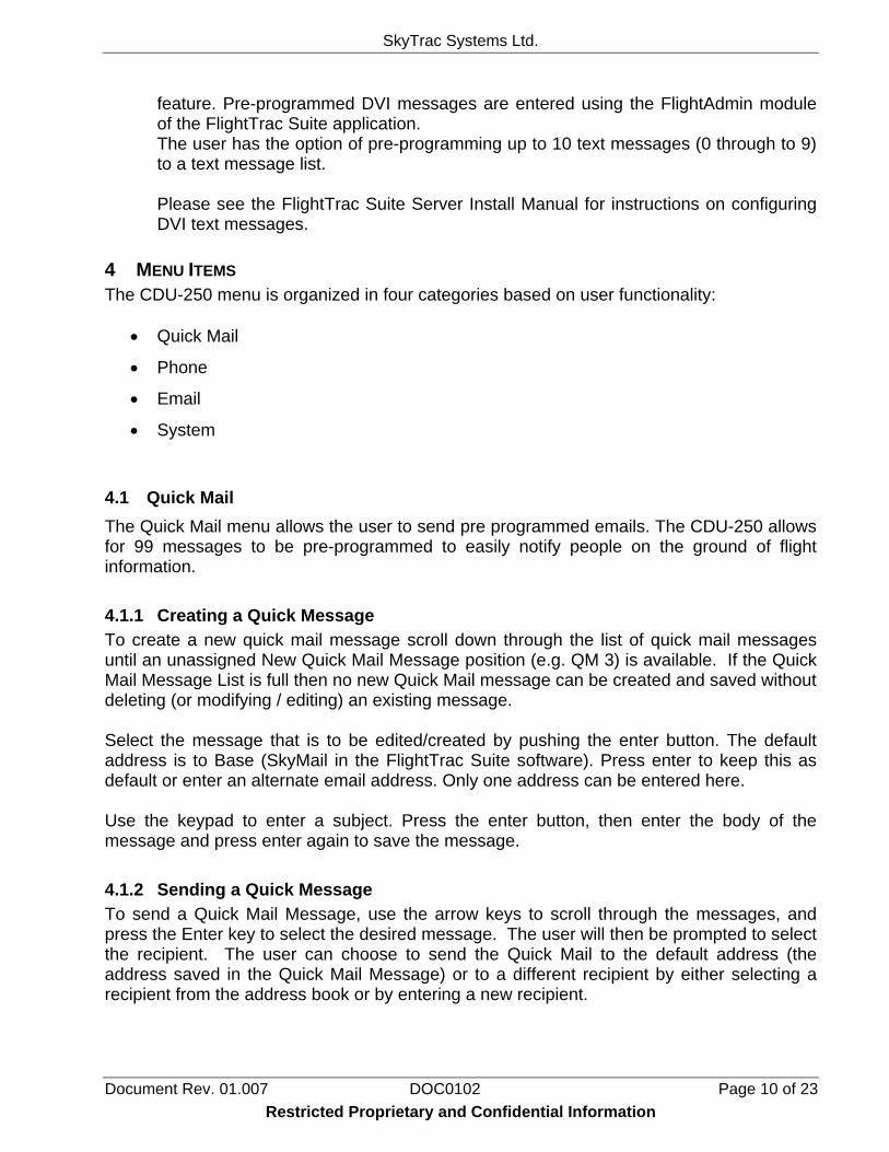
3.1.3 Information menu The Information menu provides the user timely alerts and feedback regarding the arrival of emails and phone calls, and error information such as incorrect email address and phone numbers. The Information menu times out after a specific period of time and brings the user back to the appropriate menu. Pressing the Enter key ends the Information menu immediately. This menu is only for notifications; all the navigation keys except the Enter key have no functionality in this menu.
Info
Address Book Empty
Menu Title
Info or ErrorMessage
3.1.4 Hotkey Support The CDU-250 has built in hotkey functionality for commonly used features to enable quick access without menu navigation. The following Hotkey actions are supported from the Home Menu only:
Manual Dial - Dial the desired number on the keypad and press Send to initiate a call. Speed Dial – Entries 1-9 in the Address Book are set for speed dial numbers. Press the number of the speed dial and press Send to initiate a quick dial. Redial – Press 0 and then press Send to initiate a redial of the last number called. Text Message – Press the # key. This will bring up the Text Message menu. Enter a message number (0 through to 9) to be sent. Then press the Send key to send the message to the FlightTrac Suite application. Note: Text messages are separate from Quick Mail. Text messages are a DVI-250 feature which operates in conjunction with the SkyTrac Flight Suite software. This functionality is made available to CDU-250 users who would also like to use this
Restricted Proprietary and Confidential Information
SkyTrac Systems Ltd.
Document Rev. 01.007 DOC0102 Page 10 of 23 Restricted Proprietary and Confidential Information
feature. Pre-programmed DVI messages are entered using the FlightAdmin module of the FlightTrac Suite application. The user has the option of pre-programming up to 10 text messages (0 through to 9) to a text message list. Please see the FlightTrac Suite Server Install Manual for instructions on configuring DVI text messages.
4 MENU ITEMS The CDU-250 menu is organized in four categories based on user functionality:
• Quick Mail
• Phone
• System
4.1 Quick Mail The Quick Mail menu allows the user to send pre programmed emails. The CDU-250 allows for 99 messages to be pre-programmed to easily notify people on the ground of flight information. 4.1.1 Creating a Quick Message To create a new quick mail message scroll down through the list of quick mail messages until an unassigned New Quick Mail Message position (e.g. QM 3) is available. If the Quick Mail Message List is full then no new Quick Mail message can be created and saved without deleting (or modifying / editing) an existing message. Select the message that is to be edited/created by pushing the enter button. The default address is to Base (SkyMail in the FlightTrac Suite software). Press enter to keep this as default or enter an alternate email address. Only one address can be entered here. Use the keypad to enter a subject. Press the enter button, then enter the body of the message and press enter again to save the message. 4.1.2 Sending a Quick Message To send a Quick Mail Message, use the arrow keys to scroll through the messages, and press the Enter key to select the desired message. The user will then be prompted to select the recipient. The user can choose to send the Quick Mail to the default address (the address saved in the Quick Mail Message) or to a different recipient by either selecting a recipient from the address book or by entering a new recipient.
SkyTrac Systems Ltd.
Document Rev. 01.007 DOC0102 Page 11 of 23 Restricted Proprietary and Confidential Information
The up and down arrow keys will scroll through the message list one at a time. The left and right arrow keys will move through the list ten at a time. 4.1.3 Editable Field Messages (EFM) A Quick Message can also be configured to have preset editable fields. In order to use this type of messages, the CDU-250 must be pre-programmed using the SkyWeb Hardware Management Console (HMC) or the SkyNet Serial Tool (please contact SkyTrac Systems for details). Once a Quick Message has been set with editable fields, the message will say “EFM” across the top line of the selected message. Press enter to select the message and choose the recipient. The cursor will automatically bump to the field that is to be edited. A list of possible options will have been set in the original programming. Use the up and down arrow keys to scroll through the list of preset options, or use the keypad to enter in the information manually. Once the field has been populated, the cursor will automatically jump to the next editable field (if there is one). Once all of the fields have the requested information, press the enter button to send the message.
4.2 Phone The Phone menu allows the user to make calls. There are three options under the Phone menu item:
• Addr Book Dial – dial a number that has been saved in the address book • Redial – dials the previously called number • Manual Dial – manually dial a phone number
Regardless of the type of dialling that is being done, an international number must be entered. To place a call, dial an international number: International Direct Dialling (IDD) prefix of the country being called from (00 for Iridium) then the destination country code (1 for Canada and the US), followed by the area code and local number. For example, to call SkyTrac Systems office, dial: 00 1 250 765 2393 Once a call has been initiated, the Activity indicator will stay on solid indicating the ISAT is initiating the call. The Display also indicates the status of the call. It may take a moment for the ISAT to initiate the call if it is already busy communicating with the Iridium network. To hang-up simply press the Send button again. When a call is being initiated by the ISAT, the user will hear a periodic beep. If the call fails, the user will hear beeps to indicate the signal was lost. If the signal is lost, the call will end and the Activity indicator will go out.
SkyTrac Systems Ltd.
Document Rev. 01.007 DOC0102 Page 12 of 23 Restricted Proprietary and Confidential Information
The user will hear a normal telephone ring when the call connects. 4.2.1 Address Book Dial The Phone Menu also has an option to browse through the Address book and select a number to call. Select Addr Book from the Phone menu. Use the arrow keys to scroll through the address book to the number that is to be dialled, then press the Send button. The up and down buttons will scroll through one by one, and the left and right keys will move through the address book ten entries at a time. Address Book entries 1 through 9 can be speed dialled using the hotkeys on the keypad. Press the number of the entry and press Send to initiate a speed dial. 4.2.2 Manual Dial To dial a phone number, go to the Manual Dial Menu and enter the number using the keypad, then press the Send key. An international number as described above must be dialled regardless of the location of the aircraft. A phone number can also be manually dialled from home the Home menu by simply entering the number on the keypad and pressing Send. 4.2.3 Redial The Phone menu has a ‘Redial’ option. Also, pressing the ‘0’ key followed by the Send button will place a call to the last number dialled. If there is no last number stored, the CDU-250 will display an error message. The last number dialled is erased when the CDU-250 restarts. 4.2.4 Incoming Call In order to dial the ISAT from the ground, an international number must also be dialled. The country code for the Iridium Satellite network is 8816 or 8817. To dial an international number, dial the International Direct Dialling (IDD) prefix of the country being called from (011 for Canada and the US) then the destination country code (8816), followed by the ISAT’s number. Example: 011 8816 3101 0616 When a call comes in to the ISAT, the CDU-250 Activity indicator will illuminate and an audible ring will be heard on the headset. The CDU-250 Display will also show a message indicating an incoming call. If installed, the optional external buzzer will also sound. To answer an incoming call, press the Send button. When the call is answered the Activity light becomes solid and the display will update the current status of the call.
SkyTrac Systems Ltd.
Document Rev. 01.007 DOC0102 Page 13 of 23 Restricted Proprietary and Confidential Information
When finished, press the Send button again to hang up. The Activity indicator will go out when the ISAT hangs up the call. If the ground user hangs up, it may take the Iridium system a few moments to detect the hang up before the ISAT will automatically end the call. Once the call ends the menu will return to the previously active menu. It may take several attempts to connect to the Iridium network when dialling the ISAT from the ground. If the first attempt fails, try again. 4.2.5 Dialling DTMF Tones during a Phone Call The CDU-250 can generate DTMF tones enabling the user to access automated voice menus. The user will not hear the DTMF tones over the headset; the tones will only be heard on the receiving end. DTMF Tones can only be dialled once a phone call is already in progress. In order to dial a DTMF tone, press the pound key “#” and the desired key to generate a tone. This sequence must be repeated for each tone desired. For example to send the DTMF tones for numbers 5768# to an automated menu, press # 5, # 7, # 6 # 8, # #. Allow the Activity indicator to flash twice between successive digits. 4.2.6 Volume Control The CDU-250 allows changing the volume only when a call is on progress. The CDU-250 has four volume settings. During a Call, the volume adjust menu is displayed automatically. To change the volume during a call, simply press the Up key to increase the volume, or Down Key to lower the volume. NOTE: It may take up to 30 seconds for the volume to adjust.
4.3 Email The CDU-250 supports Email that functions similar to PC based email programs. 4.3.1 Inbox The Inbox option allows the user to view and read all messages received from the ISAT. Sub options include: Read, Reply, and Delete. The CDU-250 can store 25 messages in the Inbox. After that the CDU-250 will automatically delete the oldest message in the list to make room for new messages. If installed, the optional external buzzer will sound whenever a new mail message arrives in the Inbox. The CDU-250 will also display an information message on its screen to alert the user.
SkyTrac Systems Ltd.
Document Rev. 01.007 DOC0102 Page 14 of 23 Restricted Proprietary and Confidential Information
4.3.2 Compose The Compose menu allows the user to compose a new email message which is to be sent using the ISAT. If the email message has no email address, it will be considered a base message and be sent to the FlightTrac Suite or SkyWeb applications. 4.3.3 Outbox The Outbox has the list of all the mails that are queued to be sent from the CDU-250 to the ISAT. If messages are not being emptied from the Outbox then the CDU-250 is not able to communicate with the ISAT. Sub options include: Read and Delete. Once a mail is sent, the mail will be removed from the Outbox and copied to Sentbox. 4.3.4 Sentbox The Sentbox has the list of the last 10 email messages sent from the CDU-250 to the ISAT. Sentbox will store only 10 messages after that it will overwrite the oldest message in the list. Sub options include: Read and Delete.
4.4 System Menu The system menu has the following sub-menus to set and view various system parameters:
• Addr Book – create up to 125 entries • Brightness – configure display brightness levels • System Setup – run diagnostics and clear settings • Display Off – manually turn the display off
4.4.1 Address Book Menu The Address book menu allows the user to manage the address book. The user may use this menu to create a new entry and delete or edit existing entries. T o create a new entry, navigate to System -> Addr Book and select New. Enter the name of the entry, press the enter button, add the phone number, press the enter button, and then enter an email address (if desired). The unit will then ask to save or delete the edits. 4.4.2 System Setup Menu The System Setup menu allows the user to run diagnostics and configure brightness settings.
SkyTrac Systems Ltd.
Document Rev. 01.007 DOC0102 Page 15 of 23 Restricted Proprietary and Confidential Information
4.4.2.1 Diagnostics Menu The Diagnostics menu allows the user to test the display, keypad, indicators, and Buzzer (buzzer test only applies to CDP-250 Mod-A with optional buzzer installed). All four tests can be run in sequence by selecting the “Auto” option. 4.4.2.2 Clear Menu The Clear menu allows the user to clear quick dials, email boxes, address book, or to clear all data, and Reset the System to Factory defaults via the Factory Reset option. When the CDU-250 is reset to factory settings, all the quick dials and address book entries are erased. Also all emails in Inbox, Outbox, and Sentbox are cleared, and Brightness configuration values are set to their factory default values. 4.4.3 Brightness Control There are four options, selectable from the “Brightness” menu:
• Optical Sensor Mode • Dimmer Bus Mode • Manual Override Mode • Configure
In Optical Sensor Mode, the CDU250 Display and Indicator brightness levels are automatically adjusted based on the aircraft cabin ambient lighting. In Dimmer Bus Mode the brightness levels are automatically adjusted via a cabin dimmer bus control based on the dimmer bus voltage. This method only functions if the dimmer bus has been wired to the CDU-250. The Manual Override Mode overrides any previously active automatic modes (Optical Sensor Mode or Dimmer Bus Mode) and lets the user manually adjust the brightness using the menus or the Function Bright/Dim commands via the keypad. 4.4.3.1 Optical Sensor Brightness Mode In optical sensor brightness mode, the CDU-250 senses the aircraft cabin ambient lighting using the light sensor present in the Display panel and sets the brightness of the display, indicators and backlight proportional to the aircraft cabin ambient lighting. The Optical sensor updates the brightness only every 5-7 seconds to prevent display flickering in varying ambient lighting conditions that are short duration. 4.4.3.2 Dimmer Bus Mode In the Dimmer Bus Mode, the brightness of the CDU-250 backlights and LEDs will simply follow the voltage on the dimmer bus until the voltage set by the “Dimmer Bus Volt” Menu is reached. Afterwards, the display and backlights will remain at maximum brightness.
SkyTrac Systems Ltd.
Document Rev. 01.007 DOC0102 Page 16 of 23 Restricted Proprietary and Confidential Information
The exception is when the voltage falls below a configured minimum threshold, and the optical sensor indicates a bright cabin, then the backlights and LEDs will be set to maximum brightness. This feature ensures that during bright daylight when the dimmer bus is off, the Display and indicators are at their maximum brightness. The threshold at which this occurs can be configured at the “Dimmer Threshold” menu option. Setting the Dimmer Threshold to 0 disables the daylight mode behaviour, and this may be desirable for certain conditions. The user can also vary the relative ambient brightness required to trigger a daylight response via the “Daylight Threshold” menu option. 4.4.3.3 Manual Mode Manual Mode overrides the brightness control for the indicators, backlight brightness, and the LED display until the next power-up or until control is switched back to either the optical sensor or dimmer bus mode by menu selection. Manual Mode Menu has two options, brighter or dimmer. Select the desired action as many times as desired until required brightness levels are reached. The relative brightness value within the range of 1 – 15 is indicated on the display when manual brightness is adjusted. 4.4.3.4 Configure Bright/Dim Control 4.4.3.4.1 Optical Sensor Gain The behaviour of the Optical Sensor Mode brightness can be customized by adjusting the Optical Sensor Gain. The Gain value can be changed from the System > Brightness > Configure > Opt Sensor Gain Menu. A value between 0 – 99 can be specified for the Optical Sensor Gain. When using Optical Sensor Mode: - If the display is too dim for flying conditions increase the Optical Sensor Gain. - If the display is too bright for flying conditions, decrease the Optical Sensor Gain. When adjusting the optical sensor gain, ensure the display brightness is appropriate for low light conditions as well as bright daylight conditions. Adjusting the Optical Sensor Gain towards maximum, results in the display reaching its’ maximum brightness below maximum ambient lighting conditions. Increasing the Optical Sensor Gain when the ambient lighting is bright may result in no brightness level changes at the current ambient lighting level (system already at maximum brightness), but increased brightness at dimmer ambient light levels may occur. 4.4.3.4.2 Daylight Thresh The “Daylight Threshold” provides the option to increase or decrease the ambient light level of the cabin that is required for the CDP-250 to switch to full brightness if the voltage on the dimmer bus falls below the Dimmer Threshold. This value is relative, with 1 being the dimmest and 9 being the brightest.
SkyTrac Systems Ltd.
Document Rev. 01.007 DOC0102 Page 17 of 23 Restricted Proprietary and Confidential Information
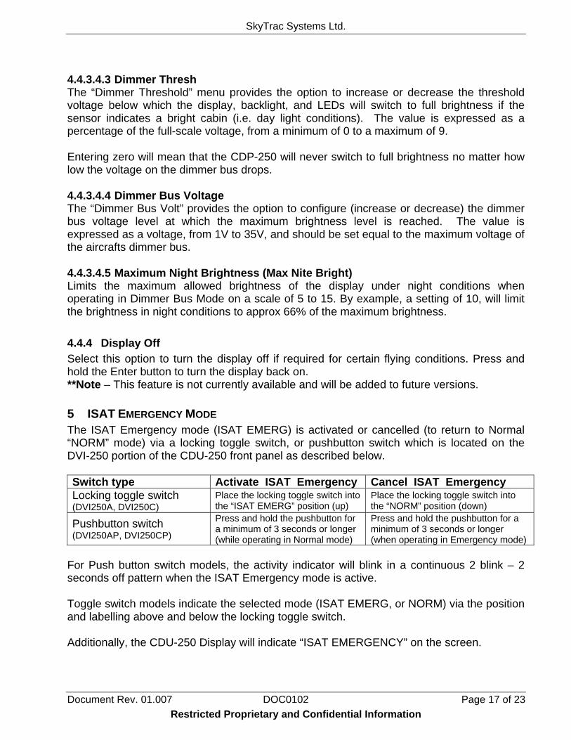
4.4.3.4.3 Dimmer Thresh The “Dimmer Threshold” menu provides the option to increase or decrease the threshold voltage below which the display, backlight, and LEDs will switch to full brightness if the sensor indicates a bright cabin (i.e. day light conditions). The value is expressed as a percentage of the full-scale voltage, from a minimum of 0 to a maximum of 9. Entering zero will mean that the CDP-250 will never switch to full brightness no matter how low the voltage on the dimmer bus drops. 4.4.3.4.4 Dimmer Bus Voltage The “Dimmer Bus Volt” provides the option to configure (increase or decrease) the dimmer bus voltage level at which the maximum brightness level is reached. The value is expressed as a voltage, from 1V to 35V, and should be set equal to the maximum voltage of the aircrafts dimmer bus. 4.4.3.4.5 Maximum Night Brightness (Max Nite Bright) Limits the maximum allowed brightness of the display under night conditions when operating in Dimmer Bus Mode on a scale of 5 to 15. By example, a setting of 10, will limit the brightness in night conditions to approx 66% of the maximum brightness. 4.4.4 Display Off Select this option to turn the display off if required for certain flying conditions. Press and hold the Enter button to turn the display back on. **Note – This feature is not currently available and will be added to future versions. 5 ISAT EMERGENCY MODE The ISAT Emergency mode (ISAT EMERG) is activated or cancelled (to return to Normal “NORM” mode) via a locking toggle switch, or pushbutton switch which is located on the DVI-250 portion of the CDU-250 front panel as described below. Switch type Activate ISAT Emergency Cancel ISAT Emergency Locking toggle switch (DVI250A, DVI250C)
Place the locking toggle switch into the “ISAT EMERG” position (up)
Place the locking toggle switch into the “NORM” position (down)
Pushbutton switch (DVI250AP, DVI250CP)
Press and hold the pushbutton for a minimum of 3 seconds or longer (while operating in Normal mode)
Press and hold the pushbutton for a minimum of 3 seconds or longer (when operating in Emergency mode)
For Push button switch models, the activity indicator will blink in a continuous 2 blink – 2 seconds off pattern when the ISAT Emergency mode is active. Toggle switch models indicate the selected mode (ISAT EMERG, or NORM) via the position and labelling above and below the locking toggle switch. Additionally, the CDU-250 Display will indicate “ISAT EMERGENCY” on the screen.
SkyTrac Systems Ltd.
Document Rev. 01.007 DOC0102 Page 18 of 23 Restricted Proprietary and Confidential Information
During ISAT emergency mode operation, the user will not be able to navigate the menu system, key presses are ignored, and the Activity indicator signals an error when buttons are pressed. The ISAT does not allow voice calls or text messages to be sent while in ISAT emergency mode. If the user is in a voice call when ISAT Emergency is triggered, the ISAT will end the voice call in order to send emergency position reports. Switching the ISAT back to Normal mode (Norm) ends the ISAT Emergency condition. 6 ACCESS CONTROL Note: The following description is valid only if PIN feature is activated in the CDU-250 The CDU-250 supports restricted access to the calling and messaging features supported by the ISAT by the use of a PIN number. PIN numbers can be used for the following purposes:
1. To prevent unauthorized access of calling and text messaging
2. To determine or track the call usage (duration) of each CDU-250 user1. PIN numbers are CDU specific. If multiple CDU’s are installed in the fleet and all require access control, each CDU must be configured individually.
6.1 PIN Description 1. The CDU-250 supports a maximum of 400 distinct PINS – i.e. the CDU -250 will be
able to identify up to a maximum of 400 distinct users.
2. The PIN length can be 4, 5 or 6 digits. The length selected applies to all the PINS used in the CDU-250.
3. For each PIN, an access level can be configured to:
• Enable/Disable incoming calls • Enable/Disable outgoing calls • Enable/Disable incoming emails • Enable/Disable outgoing emails • Enable/Disable outgoing text messages
4. When the PIN feature is activated, a default access level must be set for the CDU-
250. This default access level will be used if no PIN is entered in to the CDU-250 or when an invalid PIN is entered to the CDU-250. For example, if the default access level is set to disable outgoing calls and messaging, then a user cannot make an outgoing call unless they enter a PIN with an access level to make outgoing calls.
1 This feature requires an ISAT-100 firmware revision 2.18 or later.
SkyTrac Systems Ltd.
Document Rev. 01.007 DOC0102 Page 19 of 23 Restricted Proprietary and Confidential Information
6.2 Activating the PIN Feature To activate the PIN feature in the CDU -250, please contact SkyTrac Systems. Use the SkyNet Serial Tool Program to assign access levels to the PIN numbers. If the PIN feature is not activated, then there are no restrictions to calling or messaging. All users will have full access to Sat Phone calling, email, and DVI text messaging. Once the PIN feature is activated, the Pin Management menu option will appear in the System Menu. At any time, the CDU -250 can be set to use the default access level by selecting the System Pin Management Use Default PIN option.
6.3 Entering PINS in CDU When the CDU-250 starts-up, it will prompt the user to enter a PIN. If a valid PIN is entered then the access level corresponding to the PIN are used. If an invalid PIN is entered the default access level is used. The assigned PIN has to be entered every time the CDU-250 powers-up. In order to log off of the CDU without removing main power, navigate to the System Pin Management menu option. The CDU will then return to the main menu and ask for a PIN number to be entered. 7 SUPPORT FOR CONNECTING MULTIPLE DEVICES The DVI firmware release (1.04+) and CDP firmware release (1.01+) support connecting multiple devices to the ISAT-100. One device configured for the default message mailbox connected to the RS232 bus, and a CDU-250 connected to the RS485 bus, and configured for different message mailbox. If the CDU-250 (which connects to the RS485 connector) is the only device connected to the ISAT-100, it will automatically take the default mailbox (mailbox number 0). If there are multiple devices connected to the ISAT-100, the device that is connected to the RS232 connector will always take the default mailbox. A maximum of two devices can be connected to the ISAT-100. When multiple devices are connected to the ISAT-100, each device can be used to make calls and send emails and text messages as described in the previous sections of this user guide. To receive emails properly the device on the RS485 bus must be assigned a different unique message mailbox number between 1 and 3. The mailbox number can be set from the System Set Mailbox # menu option.
SkyTrac Systems Ltd.
Document Rev. 01.007 DOC0102 Page 20 of 23 Restricted Proprietary and Confidential Information
For example, if an external device (Eg. Palm device using SkyTrac Palm ITRAX software) is connected to the RS232 bus, and a CDU-250 is connected to the ISAT-100, one possible mailbox assignment for the CDU-250 is:
• Palm is the default (no configuration necessary) • CDU-250 – Mailbox 3
If the ISAT’s call sign is “ISAT_1000”, to send email to the Palm device using the default message mailbox (0), the email address would be [email protected]. To send an email to an additional device, the assigned mailbox number needs to be added to the email address of the ISAT. In this example, the CDU-250 has been assigned message mailbox 3. Therefore, the email address of the CDU will be [email protected]. Configuring both devices to have the same message mailbox number is not supported. Connecting two devices on the same bus is currently not supported. Devices that are configured to have their own message mailboxes will have private messaging only. Voice communication, regardless of the number of interfaces attached, is still controlled by the single ISAT-100. All voice calls will go through the aircraft audio panel and will not be private. 8 INSTALLING FIRMWARE SkyTrac Systems will periodically supply new version of firmware that will add functionality to the CDU-250. These files will be available on the SkyTrac website (www.skytrac.ca) to download and be installed on both the CDP and DVI sections. If new firmware versions are available for both the CDP-250 and DVI-250, they do not have to be installed in any particular order.
8.1 Requirements You will need the following to perform a DVI-250 firmware upload:
- Windows PC with an available serial port. - 9-wire Serial Cable to connect the PC to the DVI-250 and CDP-250 programming
ports. - Alternatively, a USB to serial cable may be used in place of a 9-wire serial cable. - The latest DVI-250 and CDP-250 firmware upload packages
8.2 Firmware Upgrade Instructions These instructions are for the DVI portion of the CDU-250. If a CDP upgrade is required as well, follow the same steps but connect the cable to the programming port on the CDP-250.
SkyTrac Systems Ltd.
Document Rev. 01.007 DOC0102 Page 21 of 23
1. Connect the Serial Cable to a serial port on the Windows PC. Connect the other end of the Serial Cable to the DB-9 programming port connector on the back of the DVI-250.
2. Extract the DVI-250-xxx-Upload.zip file to a directory on the Windows PC.
3. Apply power to the DVI-250.
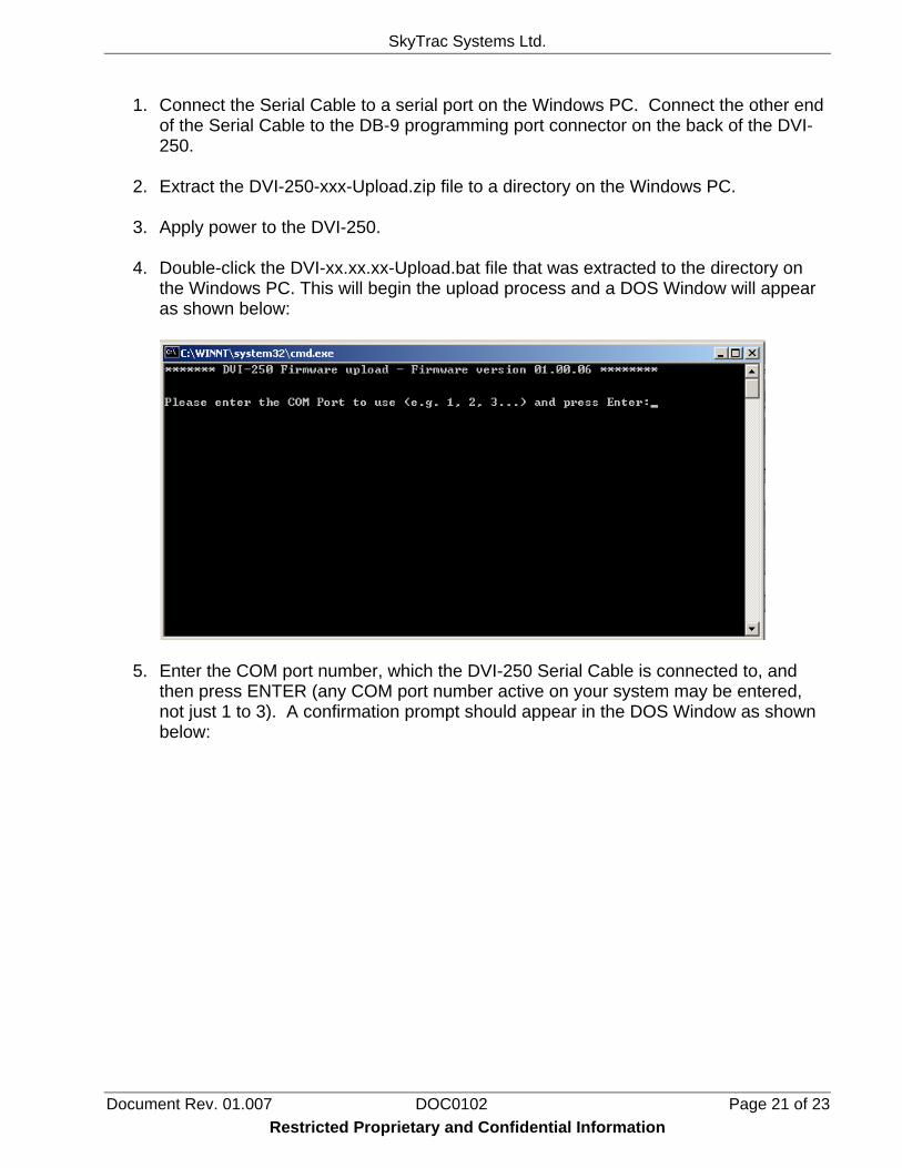
4. Double-click the DVI-xx.xx.xx-Upload.bat file that was extracted to the directory on
the Windows PC. This will begin the upload process and a DOS Window will appear as shown below:
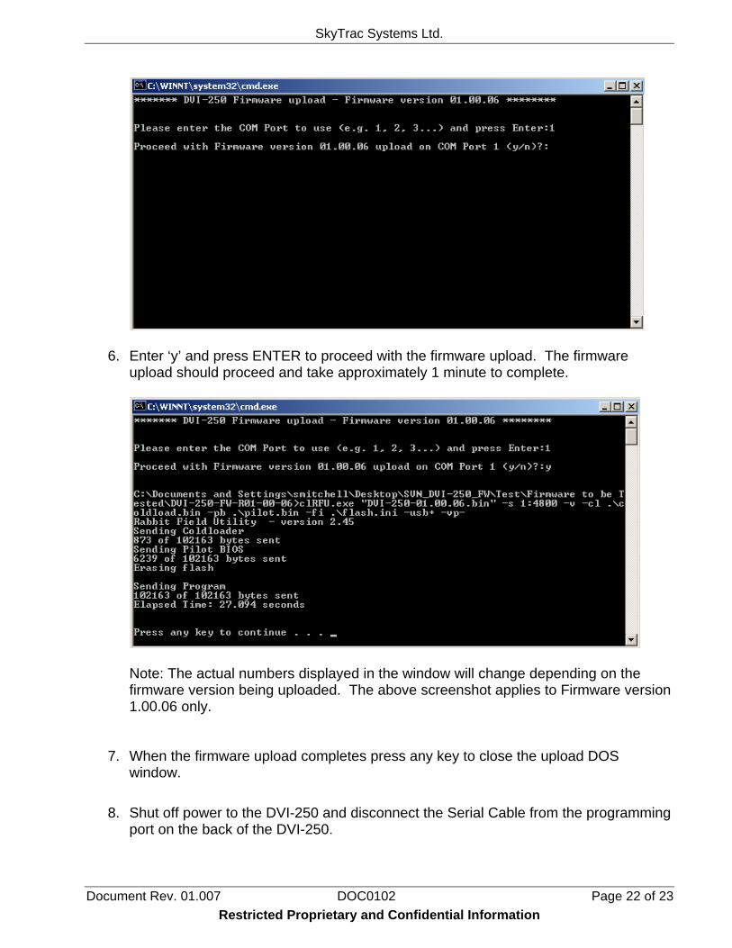
5. Enter the COM port number, which the DVI-250 Serial Cable is connected to, and then press ENTER (any COM port number active on your system may be entered, not just 1 to 3). A confirmation prompt should appear in the DOS Window as shown below:
Restricted Proprietary and Confidential Information
SkyTrac Systems Ltd.
Document Rev. 01.007 DOC0102 Page 22 of 23
6. Enter ‘y’ and press ENTER to proceed with the firmware upload. The firmware upload should proceed and take approximately 1 minute to complete.
Note: The actual numbers displayed in the window will change depending on the firmware version being uploaded. The above screenshot applies to Firmware version 1.00.06 only.
7. When the firmware upload completes press any key to close the upload DOS window.
8. Shut off power to the DVI-250 and disconnect the Serial Cable from the programming
port on the back of the DVI-250.
Restricted Proprietary and Confidential Information
SkyTrac Systems Ltd.
Document Rev. 01.007 DOC0102 Page 23 of 23 Restricted Proprietary and Confidential Information
9. Apply power to the DVI-250. Verify that the DVI-250 starts up.
10. Follow the same steps for the CDP-250 if required.