Embed Size (px)
Citation preview

nalcore n erg yCONTRACTOR FRONT SHEET
LOWER CHURCHILL PROJECT
Contract Number and Description: Contractor Name:
LC-E N-02 1 Tideway Offshore Contractors
Document Title: Total Pages
(Inc. Cover):Shore Approach Feasibility Study Report
46 excl. App
Contractor Document Number Contractor Rev, DateContractor Approval - Name
and Signature
1W-10124-REP-O1 03 15/02/11 P. Scheers
ESubmitted For; Nalcor Energy- Lower Churchill Project
INFO REVIEW
REVIEWDOUSNOTCONSTITJTEAFFROVALOF DESIRN DETAILS, CALCULATIONS, E ui ment Ta'1 VTEST METHOD OR MATERIAL DEVEL.OPLENT OR SELECTED EU CONTRACTOR, NORDOES IT RELIEVE THE CONTRACTOR FROM FULL COMPLIANCE WITH Number:CONTRACTURAL OR OTHER OSLIGATIONS
1. ACCEPTED, WORK MAY PROCEED
o 2. ACCEPTED, PROCEED WITH WORK AND INCORPORATECOMMENTS, REVSE AND RESUBMJT. Model #:
fl 3. NOT ACCEPTED, WORK MAY NOT PROCEED. REVISEAND RESUBMT.
4. FOR INFORMATION ONLY
NE-LCP SIGNATUR e._._-'_ NE - LCP DOCUMENT R:
_DATE: ,. zoI j ILK-TW-ED-0000-EN-RP-0002-O1 rBl
Muskrat Falls Project - CE-43 Rev. 2 (Public) Page 1 of 72
Nalcor Energy Lower Churchill Project Shore Approach Feasibility Study Study Report
Tideway Project No.: T-CA-10.124 Revision 03, February 2011
Tideway bv Member of the DEME Group Minervum 7442 - P.O. Box 7074 4800 GB Breda, The Netherlands T +31 76 5204140 F +31 76 5204150 [email protected] www.tideway.nl
Muskrat Falls Project - CE-43 Rev. 2 (Public) Page 2 of 72
Nalcor Energy
Lower Churchill Project Pipeline Shore Approach and Landfall Study
Tideway Project T-CA-10.124
Revision 03 2 of 46 February 2011
TABLE OF CONTENT
1 GENERAL .............................................................................................................................................. 3
1.1 INTRODUCTION................................................................................................................................. 3 1.2 SCOPE OF STUDY ............................................................................................................................ 4
2 SUMMARY, CONCLUSIONS & RECOMMENDATIONS.............................................................. 5 3 BASIS OF DESIGN................................................................................................................................ 6
3.1 LANDFALL LOCATIONS ..................................................................................................................... 6 3.2 BATHYMETRICAL DATA .................................................................................................................... 7 3.3 BURIAL REQUIREMENTS .................................................................................................................. 8 3.4 WAVE DATA ..................................................................................................................................... 8 3.5 CURRENT DATA ............................................................................................................................... 8 3.6 TIDAL DATA ...................................................................................................................................... 9 3.7 ICE DATA .......................................................................................................................................... 9 3.8 SOIL CONDITIONS .......................................................................................................................... 10
4 LANDFALL INSTALLATION METHODOLOGIES ..................................................................... 11 4.1 OPEN EXCAVATION ........................................................................................................................ 11 4.2 HORZONTAL DIRECTIONAL DRILLING (HDD) ................................................................................ 14 4.3 TUNNELING .................................................................................................................................... 16
5 SHORE APPROACH CONSTRUCTION TECHNIQUES.............................................................. 20 5.1 TRAILING SUCTION HOPPER DREDGER ........................................................................................ 20 5.2 CUTTER SUCTION DREDGER ......................................................................................................... 21 5.3 BACKHOE DREDGER ...................................................................................................................... 22 5.4 ROCK HAMMER WITH CHISEL ........................................................................................................ 23 5.5 BLASTING ....................................................................................................................................... 24
6 LANDFALL & SHORE APPROACH ROUTING............................................................................ 25 7 LOWER CHURCHILL PROJECT SHORE APPROACH SCENARIO........................................ 27
7.1 INTRODUCTION............................................................................................................................... 27 7.2 ONSHORE & NEARSHORE TRENCH ............................................................................................... 27 7.3 OFFSHORE TRENCH ...................................................................................................................... 28 7.4 TRENCH CONFIGURATION ............................................................................................................. 28 7.5 NEWFOUNDLAND SHORE APPROACH............................................................................................ 29 7.6 LABRADOR SHORE APPROACH ..................................................................................................... 30
8 PRODUCTION AND PROJECT SCHEDULE................................................................................. 32 9 BUDGET COST ESTIMATE.............................................................................................................. 35 10 METHOD STATEMENT................................................................................................................ 37
10.1 ONSHORE & NEARSHORE.............................................................................................................. 37 10.2 OFFSHORE WORKS ....................................................................................................................... 41 10.3 TRENCH MAINTENANCE AND CLEANING........................................................................................ 42 10.4 CABLE PULL-IN ............................................................................................................................... 43 10.5 SURVEY OPERATIONS .................................................................................................................... 45
11 REFERENCES................................................................................................................................. 46 12 APPENDICES .................................................................................................................................. 46
Muskrat Falls Project - CE-43 Rev. 2 (Public) Page 3 of 72
Nalcor Energy
Lower Churchill Project Pipeline Shore Approach and Landfall Study
Tideway Project T-CA-10.124
Revision 03 3 of 46 February 2011
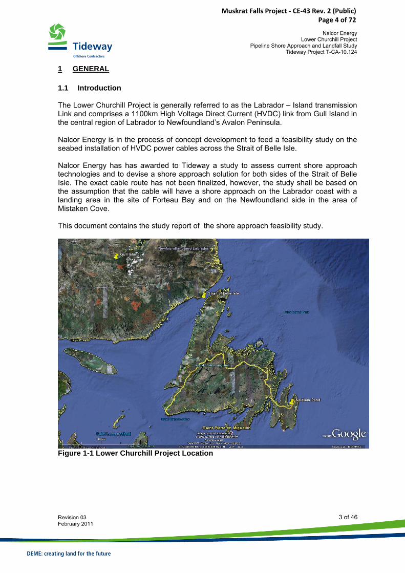
1 GENERAL 1.1 Introduction The Lower Churchill Project is generally referred to as the Labrador – Island transmission Link and comprises a 1100km High Voltage Direct Current (HVDC) link from Gull Island in the central region of Labrador to Newfoundland’s Avalon Peninsula. Nalcor Energy is in the process of concept development to feed a feasibility study on the seabed installation of HVDC power cables across the Strait of Belle Isle. Nalcor Energy has has awarded to Tideway a study to assess current shore approach technologies and to devise a shore approach solution for both sides of the Strait of Belle Isle. The exact cable route has not been finalized, however, the study shall be based on the assumption that the cable will have a shore approach on the Labrador coast with a landing area in the site of Forteau Bay and on the Newfoundland side in the area of Mistaken Cove. This document contains the study report of the shore approach feasibility study.
Figure 1-1 Lower Churchill Project Location
Muskrat Falls Project - CE-43 Rev. 2 (Public) Page 4 of 72
Nalcor Energy
Lower Churchill Project Pipeline Shore Approach and Landfall Study
Tideway Project T-CA-10.124
Revision 03 4 of 46 February 2011
1.2 Scope of Study The scope of work for the study includes the following items:
• Review of data • Landfall techniques • Shore approach techniques • Landfall/shore approach scenario • Method Statement • Production and Schedule • Cost Estimate
Muskrat Falls Project - CE-43 Rev. 2 (Public) Page 5 of 72
Nalcor Energy
Lower Churchill Project Pipeline Shore Approach and Landfall Study
Tideway Project T-CA-10.124
Revision 03 5 of 46 February 2011
2 SUMMARY, CONCLUSIONS & RECOMMENDATIONS A study was carried out to assess shore approach methodologies and construction techniques and to devise a shore approach solution for both sides of the Strait of Belle Isle for the Lower Churchill Cable Project. The following conclusions are made:
• Shore approaches at both sides of Strait of Belle Isle are feasible • Proposed solution for both shore approaches is the open excavation method • Trench excavation will be a combination of blasting followed by trench excavation • Total shore approach length at Newfoundland to achieve protection of the cable to
the 20m water depth contour is approximately 2300m • Total shore approach length at Labrador to achieve protection of the cable to the
20m water depth contour is approximately 750m • Considering the limited working window between 1st of June and 1st of January,
Construction activities will be required to take place in two seasons. • Total cost for both shore approaches are approximately Euro.
The following recommendations can be made:
• The study is based on the Company indicated burial depth and protection lengths. Optimisation of required burial depths, especially in bedrock, may have a significant impact on the volumes to be blasted and excavated and could reduce construction time considerably.
• The selected shore landing area in Mistaken Cove at the Newfoundland side, results in a fairly long shore approach and therefore large volumes of blasting and excavation. It is therefore recommended to review the shore landing location during detailed design in order to reduce the shore approach lengths.
• Ice break-up and freeze-up dates are to be considered carefully to plan mobilisation and demobilisation of equipment from the area, this may further reduce the available working window.
Muskrat Falls Project - CE-43 Rev. 2 (Public) Page 6 of 72
Nalcor Energy
Lower Churchill Project Pipeline Shore Approach and Landfall Study
Tideway Project T-CA-10.124
Revision 03 6 of 46 February 2011
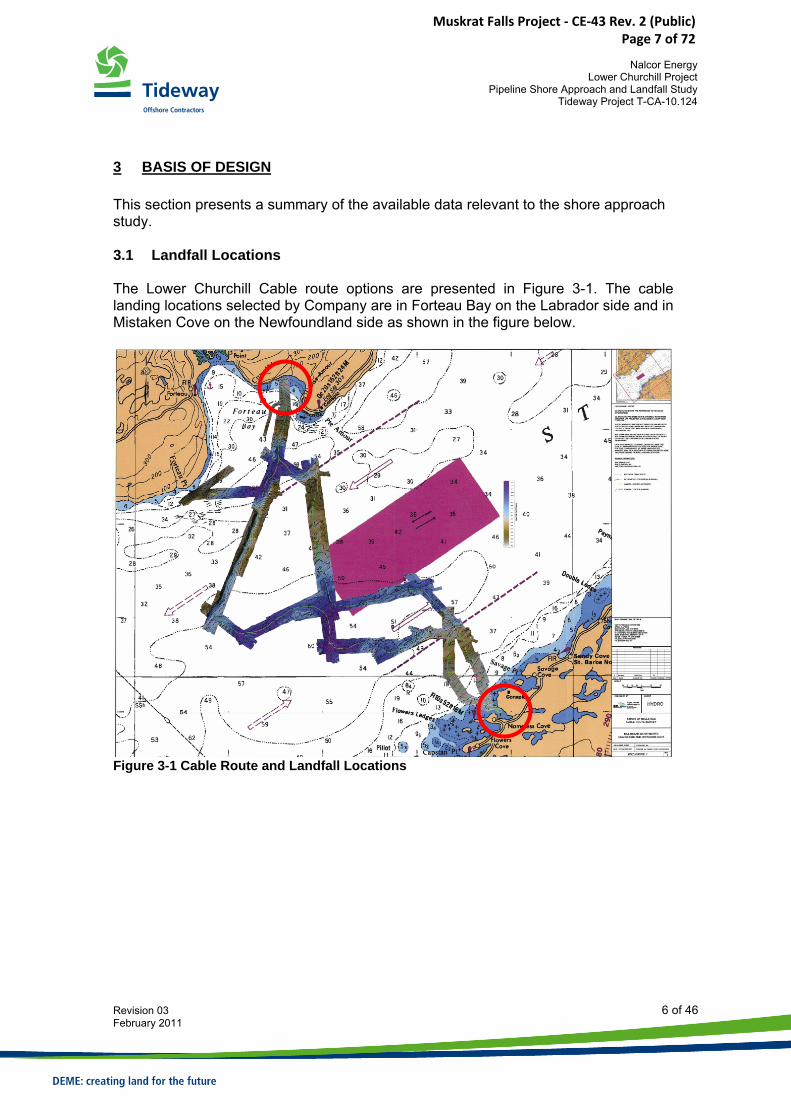
3 BASIS OF DESIGN This section presents a summary of the available data relevant to the shore approach study. 3.1 Landfall Locations The Lower Churchill Cable route options are presented in Figure 3-1. The cable landing locations selected by Company are in Forteau Bay on the Labrador side and in Mistaken Cove on the Newfoundland side as shown in the figure below.
Figure 3-1 Cable Route and Landfall Locations
Muskrat Falls Project - CE-43 Rev. 2 (Public) Page 7 of 72
Nalcor Energy
Lower Churchill Project Pipeline Shore Approach and Landfall Study
Tideway Project T-CA-10.124
Revision 03 7 of 46 February 2011
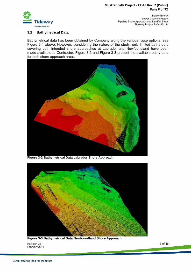
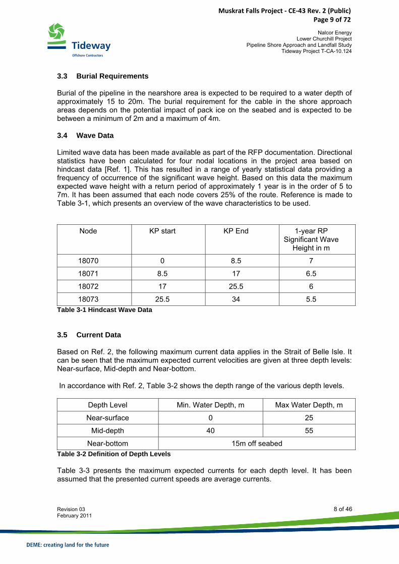
3.2 Bathymetrical Data Bathymetrical data has been obtained by Company along the various route options, see Figure 3-1 above. However, considering the nature of the study, only limited bathy data covering both intended shore approaches at Labrador and Newfoundland have been made available to Contractor. Figure 3-2 and Figure 3-3 present the available bathy data for both shore approach areas.
Figure 3-2 Bathymetrical Data Labrador Shore Approach
Figure 3-3 Bathymetrical Data Newfoundland Shore Approach
Muskrat Falls Project - CE-43 Rev. 2 (Public) Page 8 of 72
Nalcor Energy
Lower Churchill Project Pipeline Shore Approach and Landfall Study
Tideway Project T-CA-10.124
Revision 03 8 of 46 February 2011
3.3 Burial Requirements Burial of the pipeline in the nearshore area is expected to be required to a water depth of approximately 15 to 20m. The burial requirement for the cable in the shore approach areas depends on the potential impact of pack ice on the seabed and is expected to be between a minimum of 2m and a maximum of 4m. 3.4 Wave Data Limited wave data has been made available as part of the RFP documentation. Directional statistics have been calculated for four nodal locations in the project area based on hindcast data [Ref. 1]. This has resulted in a range of yearly statistical data providing a frequency of occurrence of the significant wave height. Based on this data the maximum expected wave height with a return period of approximately 1 year is in the order of 5 to 7m. It has been assumed that each node covers 25% of the route. Reference is made to Table 3-1, which presents an overview of the wave characteristics to be used.
Node KP start KP End 1-year RP Significant Wave
Height in m
18070 0 8.5 7
18071 8.5 17 6.5
18072 17 25.5 6
18073 25.5 34 5.5 Table 3-1 Hindcast Wave Data 3.5 Current Data Based on Ref. 2, the following maximum current data applies in the Strait of Belle Isle. It can be seen that the maximum expected current velocities are given at three depth levels: Near-surface, Mid-depth and Near-bottom. In accordance with Ref. 2, Table 3-2 shows the depth range of the various depth levels.
Depth Level Min. Water Depth, m Max Water Depth, m
Near-surface 0 25
Mid-depth 40 55
Near-bottom 15m off seabed Table 3-2 Definition of Depth Levels Table 3-3 presents the maximum expected currents for each depth level. It has been assumed that the presented current speeds are average currents.
Muskrat Falls Project - CE-43 Rev. 2 (Public) Page 9 of 72

Nalcor Energy
Lower Churchill Project Pipeline Shore Approach and Landfall Study
Tideway Project T-CA-10.124
Revision 03 9 of 46 February 2011
Maximum Expected Current Speed [ms-1] per Season and Depth ΔU = ±0.8 ms-1 WINTER SPRING SUMMER FALL Near Surface 3.3 3.6 4.2 4.3
Mid-Depth 3.5 3.6 4.0 3.5 Near Bottom 3.3 3.3 2.8 3.0
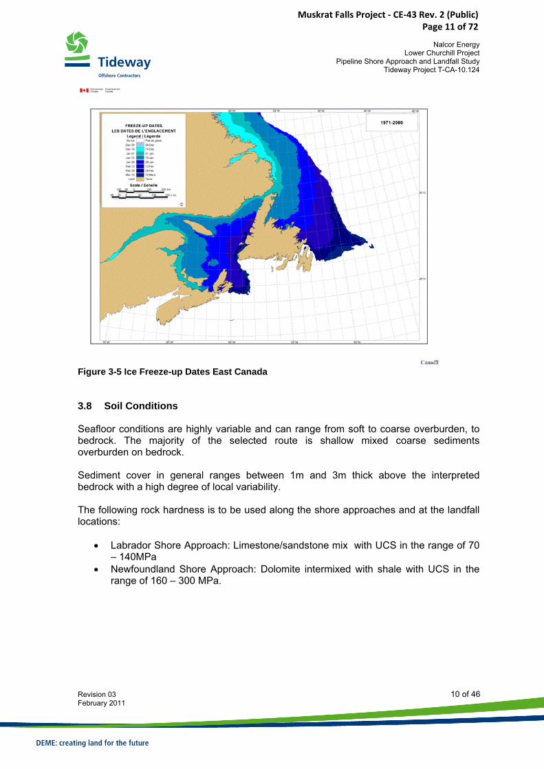
Table 3-3 Estimated Maximum Current Speeds 3.6 Tidal Data The maximum tidal difference is approximately 2.2m. 3.7 Ice Data Limited data has been provided as part of the RFP. Based on available data in the public domain (www.ice-glaces.ec.gc.ca), ice break-up and freeze-up dates have been investigated in order to define the limiting dates for the construction activities. Figure 3-4 and Figure 3-5 show freeze-up and break-up data for the eastern Canadian waters. Based on these pictures, the following Freeze-up and Break-up dates are determined and have been used in this study.
Freeze-up/Break-up Dates SOBI Date Ice Freeze-up 1st of January Ice Break-up 1st of June
Figure 3-4 Ice Break-up Dates East Canada
Muskrat Falls Project - CE-43 Rev. 2 (Public) Page 10 of 72
Nalcor Energy
Lower Churchill Project Pipeline Shore Approach and Landfall Study
Tideway Project T-CA-10.124
Revision 03 10 of 46 February 2011
Figure 3-5 Ice Freeze-up Dates East Canada 3.8 Soil Conditions Seafloor conditions are highly variable and can range from soft to coarse overburden, to bedrock. The majority of the selected route is shallow mixed coarse sediments overburden on bedrock. Sediment cover in general ranges between 1m and 3m thick above the interpreted bedrock with a high degree of local variability. The following rock hardness is to be used along the shore approaches and at the landfall locations:
• Labrador Shore Approach: Limestone/sandstone mix with UCS in the range of 70 – 140MPa
• Newfoundland Shore Approach: Dolomite intermixed with shale with UCS in the range of 160 – 300 MPa.
Muskrat Falls Project - CE-43 Rev. 2 (Public) Page 11 of 72
Nalcor Energy
Lower Churchill Project Pipeline Shore Approach and Landfall Study
Tideway Project T-CA-10.124
Revision 03 11 of 46 February 2011
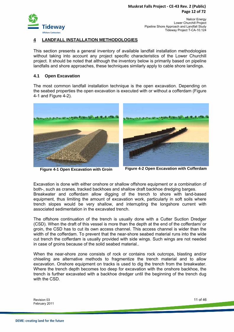
4 LANDFALL INSTALLATION METHODOLOGIES This section presents a general inventory of available landfall installation methodologies without taking into account any project specific characteristics of the Lower Churchill project. It should be noted that although the inventory below is primarily based on pipeline landfalls and shore approaches, these techniques similarly apply to cable shore landings. 4.1 Open Excavation The most common landfall installation technique is the open excavation. Depending on the seabed properties the open excavation is executed with or without a cofferdam (Figure 4-1 and Figure 4-2).
Figure 4-1 Open Excavation with Groin
Figure 4-2 Open Excavation with Cofferdam
Excavation is done with either onshore or shallow offshore equipment or a combination of both-, such as cranes, tracked backhoes and shallow draft backhoe dredging barges. Breakwater and cofferdam allow digging of the trench to shore with land-based equipment, thus limiting the amount of excavation work, particularly in soft soils where trench slopes would be very shallow, and interrupting the longshore current with associated sedimentation in the excavated trench. The offshore continuation of the trench is usually done with a Cutter Suction Dredger (CSD). When the draft of this vessel is more than the depth at the end of the cofferdam/ or groin, the CSD has to cut its own access channel. This access channel is wider than the width of the cofferdam. To prevent that the near-shore seabed material runs into the wide cut trench the cofferdam is usually provided with side wings. Such wings are not needed in case of groins because of the solid seabed material.. When the near-shore zone consists of rock or contains rock outcrops, blasting and/or chiseling are alternative methods to fragmentize the trench material and to allow excavation. Onshore equipment on tracks is used to dig the trench from the breakwater. Where the trench depth becomes too deep for excavation with the onshore backhoe, the trench is further excavated with a backhoe dredger until the beginning of the trench dug with the CSD.
Muskrat Falls Project - CE-43 Rev. 2 (Public) Page 12 of 72
Nalcor Energy
Lower Churchill Project Pipeline Shore Approach and Landfall Study
Tideway Project T-CA-10.124
Revision 03 12 of 46 February 2011
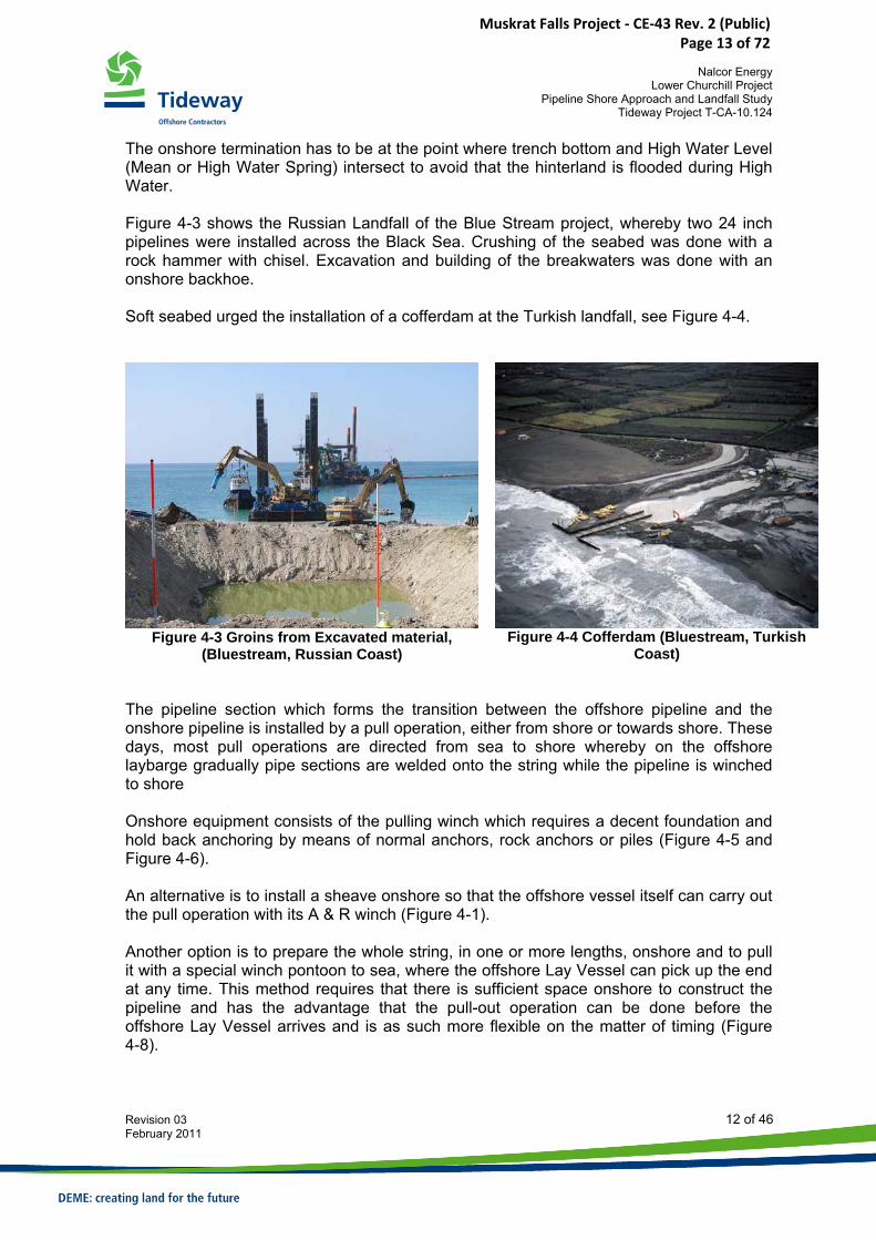
The onshore termination has to be at the point where trench bottom and High Water Level (Mean or High Water Spring) intersect to avoid that the hinterland is flooded during High Water. Figure 4-3 shows the Russian Landfall of the Blue Stream project, whereby two 24 inch pipelines were installed across the Black Sea. Crushing of the seabed was done with a rock hammer with chisel. Excavation and building of the breakwaters was done with an onshore backhoe. Soft seabed urged the installation of a cofferdam at the Turkish landfall, see Figure 4-4.
Figure 4-3 Groins from Excavated material, (Bluestream, Russian Coast)
Figure 4-4 Cofferdam (Bluestream, Turkish Coast)
The pipeline section which forms the transition between the offshore pipeline and the onshore pipeline is installed by a pull operation, either from shore or towards shore. These days, most pull operations are directed from sea to shore whereby on the offshore laybarge gradually pipe sections are welded onto the string while the pipeline is winched to shore Onshore equipment consists of the pulling winch which requires a decent foundation and hold back anchoring by means of normal anchors, rock anchors or piles (Figure 4-5 and Figure 4-6). An alternative is to install a sheave onshore so that the offshore vessel itself can carry out the pull operation with its A & R winch (Figure 4-1). Another option is to prepare the whole string, in one or more lengths, onshore and to pull it with a special winch pontoon to sea, where the offshore Lay Vessel can pick up the end at any time. This method requires that there is sufficient space onshore to construct the pipeline and has the advantage that the pull-out operation can be done before the offshore Lay Vessel arrives and is as such more flexible on the matter of timing (Figure 4-8).
Muskrat Falls Project - CE-43 Rev. 2 (Public) Page 13 of 72

Nalcor Energy
Lower Churchill Project Pipeline Shore Approach and Landfall Study
Tideway Project T-CA-10.124
Revision 03 13 of 46 February 2011
Figure 4-5 Shore Crossing with Pipeline Pulled to Shore with linear Winch (Ibiza, Spain)
Figure 4-6 Shore Crossing (Deep Panuke Project, Goldboro, Nova Scotia)
Figure 4-7 Shore Crossing with Pipeline Pulled to Shore via Onshore Sheave ( Bluestream, Russia)
Muskrat Falls Project - CE-43 Rev. 2 (Public) Page 14 of 72
Nalcor Energy
Lower Churchill Project Pipeline Shore Approach and Landfall Study
Tideway Project T-CA-10.124
Revision 03 14 of 46 February 2011
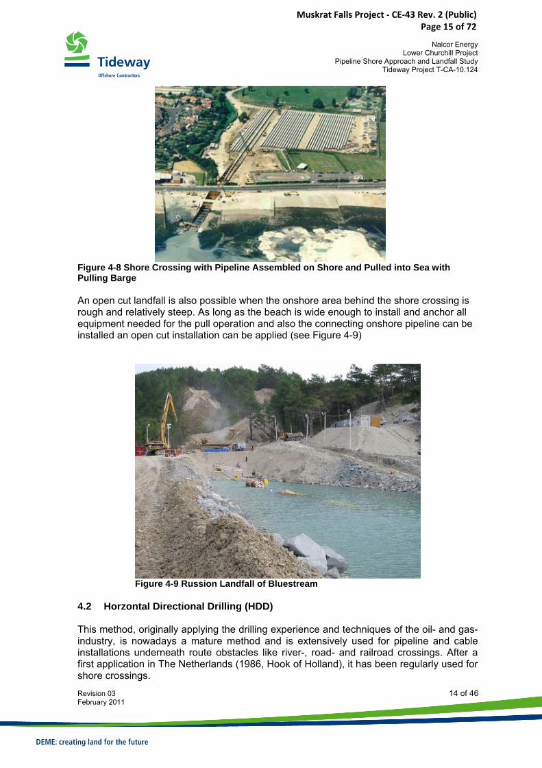
Figure 4-8 Shore Crossing with Pipeline Assembled on Shore and Pulled into Sea with Pulling Barge An open cut landfall is also possible when the onshore area behind the shore crossing is rough and relatively steep. As long as the beach is wide enough to install and anchor all equipment needed for the pull operation and also the connecting onshore pipeline can be installed an open cut installation can be applied (see Figure 4-9)
Figure 4-9 Russion Landfall of Bluestream
4.2 Horzontal Directional Drilling (HDD) This method, originally applying the drilling experience and techniques of the oil- and gas-industry, is nowadays a mature method and is extensively used for pipeline and cable installations underneath route obstacles like river-, road- and railroad crossings. After a first application in The Netherlands (1986, Hook of Holland), it has been regularly used for shore crossings.
Muskrat Falls Project - CE-43 Rev. 2 (Public) Page 15 of 72
Nalcor Energy
Lower Churchill Project Pipeline Shore Approach and Landfall Study
Tideway Project T-CA-10.124
Revision 03 15 of 46 February 2011
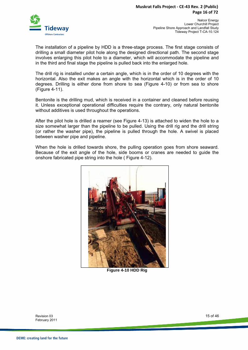
The installation of a pipeline by HDD is a three-stage process. The first stage consists of drilling a small diameter pilot hole along the designed directional path. The second stage involves enlarging this pilot hole to a diameter, which will accommodate the pipeline and in the third and final stage the pipeline is pulled back into the enlarged hole. The drill rig is installed under a certain angle, which is in the order of 10 degrees with the horizontal. Also the exit makes an angle with the horizontal which is in the order of 10 degrees. Drilling is either done from shore to sea (Figure 4-10) or from sea to shore (Figure 4-11). Bentonite is the drilling mud, which is received in a container and cleaned before reusing it. Unless exceptional operational difficulties require the contrary, only natural bentonite without additives is used throughout the operations. After the pilot hole is drilled a reamer (see Figure 4-13) is attached to widen the hole to a size somewhat larger than the pipeline to be pulled. Using the drill rig and the drill string (or rather the washer pipe), the pipeline is pulled through the hole. A swivel is placed between washer pipe and pipeline. When the hole is drilled towards shore, the pulling operation goes from shore seaward. Because of the exit angle of the hole, side booms or cranes are needed to guide the onshore fabricated pipe string into the hole ( Figure 4-12).
Figure 4-10 HDD Rig
Muskrat Falls Project - CE-43 Rev. 2 (Public) Page 16 of 72
Nalcor Energy
Lower Churchill Project Pipeline Shore Approach and Landfall Study
Tideway Project T-CA-10.124
Revision 03 16 of 46 February 2011
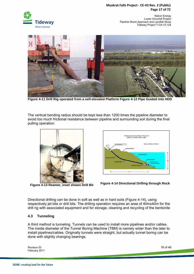
Figure 4-11 Drill Rig operated from a self-elevated Platform Figure 4-12 Pipe Guided into HDD
The vertical bending radius should be kept less than 1200 times the pipeline diameter to avoid too much frictional resistance between pipeline and surrounding soil during the final pulling operation.
Figure 4-13 Reamer, inset shows Drill Bit
Figure 4-14 Directional Drilling through Rock
Directional drilling can be done in soft as well as in hard soils (Figure 4-14), using respectively jet bits or drill bits. The drilling operation requires an area of 40mx40m for the drill rig with associated equipment and for storage, cleaning and recycling of the bentonite 4.3 Tunneling A third method is tunneling. Tunnels can be used to install more pipelines and/or cables. The inside diameter of the Tunnel Boring Machine (TBM) is namely wider than the later to install pipelines/cables. Originally tunnels were straight, but actually tunnel boring can be done with slightly changing bearings.
Muskrat Falls Project - CE-43 Rev. 2 (Public) Page 17 of 72
Nalcor Energy
Lower Churchill Project Pipeline Shore Approach and Landfall Study
Tideway Project T-CA-10.124
Revision 03 17 of 46 February 2011
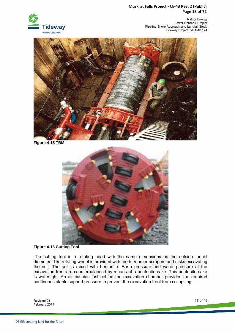
Figure 4-15 TBM
Figure 4-16 Cutting Tool The cutting tool is a rotating head with the same dimensions as the outside tunnel diameter. The rotating wheel is provided with teeth, reamer scrapers and disks excavating the soil. The soil is mixed with bentonite. Earth pressure and water pressure at the excavation front are counterbalanced by means of a bentonite cake. This bentonite cake is watertight. An air cushion just behind the excavation chamber provides the required continuous stable support pressure to prevent the excavation front from collapsing.
Muskrat Falls Project - CE-43 Rev. 2 (Public) Page 18 of 72
Nalcor Energy
Lower Churchill Project Pipeline Shore Approach and Landfall Study
Tideway Project T-CA-10.124
Revision 03 18 of 46 February 2011
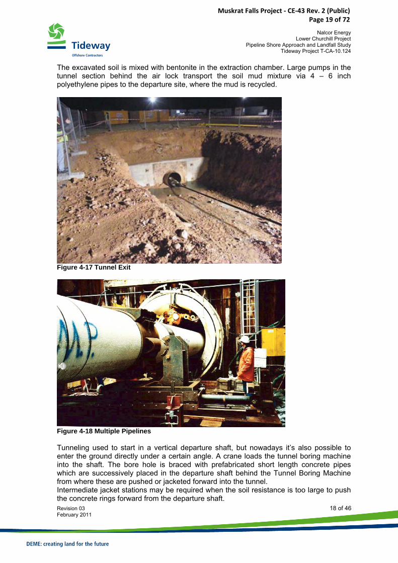
The excavated soil is mixed with bentonite in the extraction chamber. Large pumps in the tunnel section behind the air lock transport the soil mud mixture via 4 – 6 inch polyethylene pipes to the departure site, where the mud is recycled.
Figure 4-17 Tunnel Exit
Figure 4-18 Multiple Pipelines Tunneling used to start in a vertical departure shaft, but nowadays it’s also possible to enter the ground directly under a certain angle. A crane loads the tunnel boring machine into the shaft. The bore hole is braced with prefabricated short length concrete pipes which are successively placed in the departure shaft behind the Tunnel Boring Machine from where these are pushed or jacketed forward into the tunnel. Intermediate jacket stations may be required when the soil resistance is too large to push the concrete rings forward from the departure shaft.
Muskrat Falls Project - CE-43 Rev. 2 (Public) Page 19 of 72
Nalcor Energy
Lower Churchill Project Pipeline Shore Approach and Landfall Study
Tideway Project T-CA-10.124
Revision 03 19 of 46 February 2011
At the tunnel exit, a supporting vessel is required to recover the tunneling machine. When the tunnel is completed, pipelines and/or umbilicals are pulled through the annulus. Reduction of the pulling load can be achieved by flooding the tunnel. When the pipeline is preferably straight, part of the departure shaft has to be (partially) removed; otherwise the pipeline has to be continued via a riser pipe.
Muskrat Falls Project - CE-43 Rev. 2 (Public) Page 20 of 72
Nalcor Energy
Lower Churchill Project Pipeline Shore Approach and Landfall Study
Tideway Project T-CA-10.124
Revision 03 20 of 46 February 2011
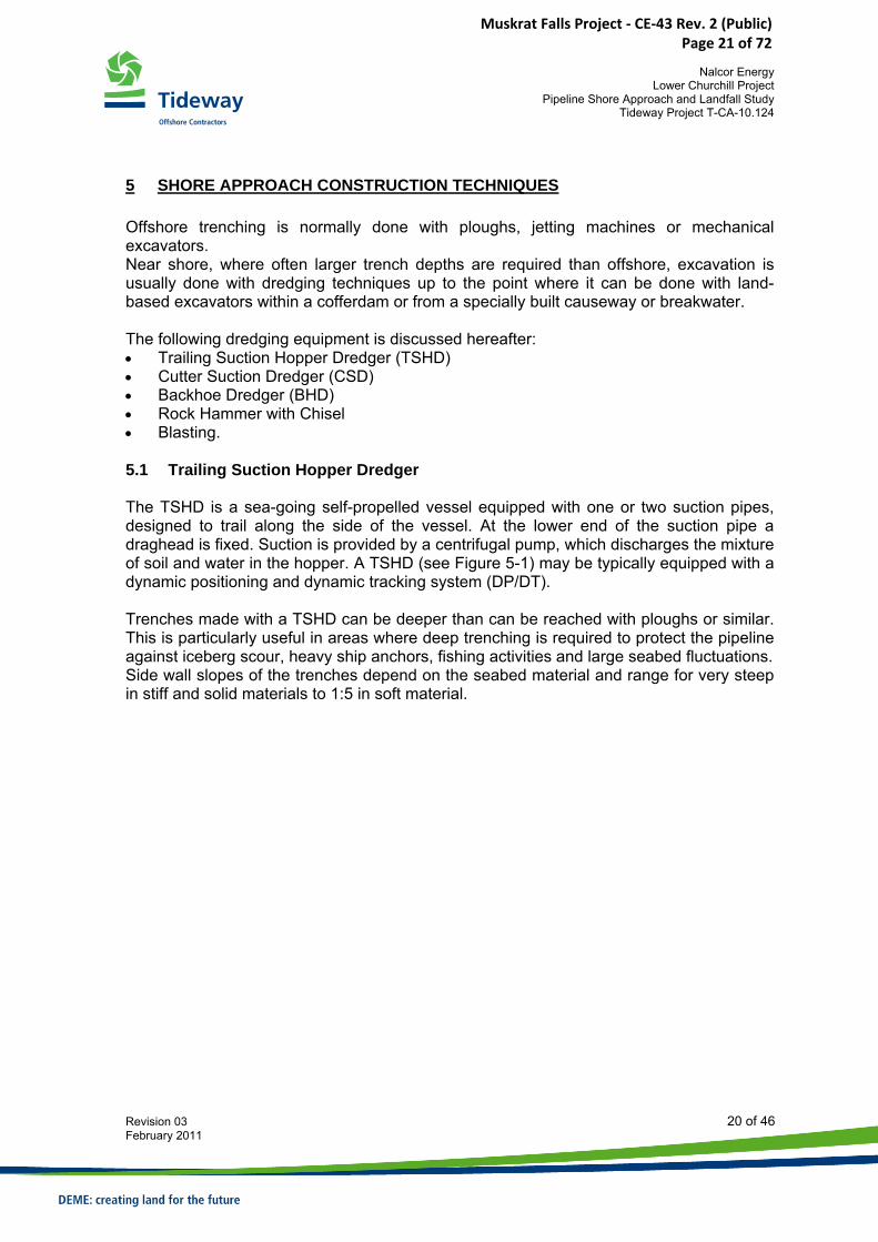
5 SHORE APPROACH CONSTRUCTION TECHNIQUES Offshore trenching is normally done with ploughs, jetting machines or mechanical excavators. Near shore, where often larger trench depths are required than offshore, excavation is usually done with dredging techniques up to the point where it can be done with land-based excavators within a cofferdam or from a specially built causeway or breakwater. The following dredging equipment is discussed hereafter: • Trailing Suction Hopper Dredger (TSHD) • Cutter Suction Dredger (CSD) • Backhoe Dredger (BHD) • Rock Hammer with Chisel • Blasting. 5.1 Trailing Suction Hopper Dredger The TSHD is a sea-going self-propelled vessel equipped with one or two suction pipes, designed to trail along the side of the vessel. At the lower end of the suction pipe a draghead is fixed. Suction is provided by a centrifugal pump, which discharges the mixture of soil and water in the hopper. A TSHD (see Figure 5-1) may be typically equipped with a dynamic positioning and dynamic tracking system (DP/DT). Trenches made with a TSHD can be deeper than can be reached with ploughs or similar. This is particularly useful in areas where deep trenching is required to protect the pipeline against iceberg scour, heavy ship anchors, fishing activities and large seabed fluctuations. Side wall slopes of the trenches depend on the seabed material and range for very steep in stiff and solid materials to 1:5 in soft material.
Muskrat Falls Project - CE-43 Rev. 2 (Public) Page 21 of 72
Nalcor Energy
Lower Churchill Project Pipeline Shore Approach and Landfall Study
Tideway Project T-CA-10.124
Revision 03 21 of 46 February 2011
Figure 5-1 Trailing Suction Hopper Dredger
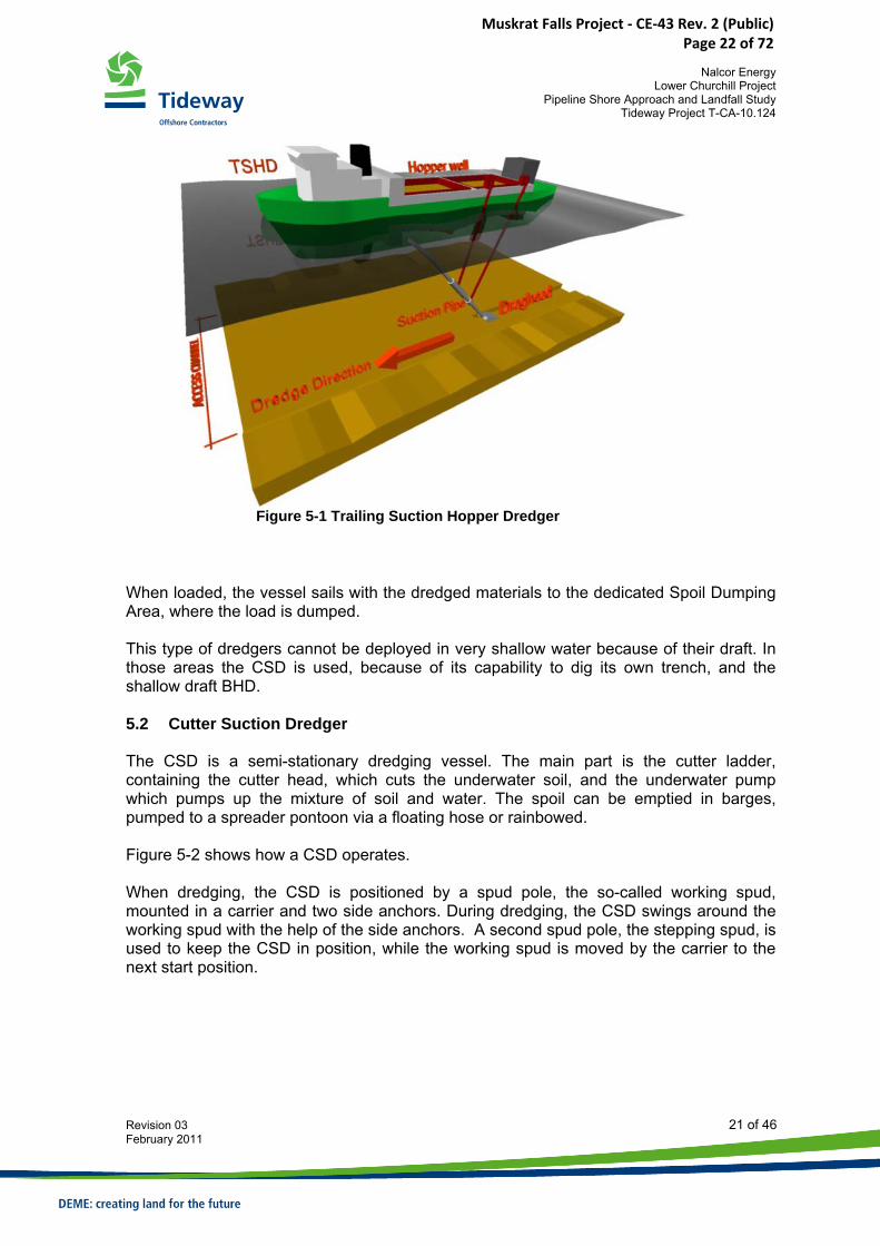
When loaded, the vessel sails with the dredged materials to the dedicated Spoil Dumping Area, where the load is dumped. This type of dredgers cannot be deployed in very shallow water because of their draft. In those areas the CSD is used, because of its capability to dig its own trench, and the shallow draft BHD. 5.2 Cutter Suction Dredger The CSD is a semi-stationary dredging vessel. The main part is the cutter ladder, containing the cutter head, which cuts the underwater soil, and the underwater pump which pumps up the mixture of soil and water. The spoil can be emptied in barges, pumped to a spreader pontoon via a floating hose or rainbowed. Figure 5-2 shows how a CSD operates. When dredging, the CSD is positioned by a spud pole, the so-called working spud, mounted in a carrier and two side anchors. During dredging, the CSD swings around the working spud with the help of the side anchors. A second spud pole, the stepping spud, is used to keep the CSD in position, while the working spud is moved by the carrier to the next start position.
Muskrat Falls Project - CE-43 Rev. 2 (Public) Page 22 of 72
Nalcor Energy
Lower Churchill Project Pipeline Shore Approach and Landfall Study
Tideway Project T-CA-10.124
Revision 03 22 of 46 February 2011
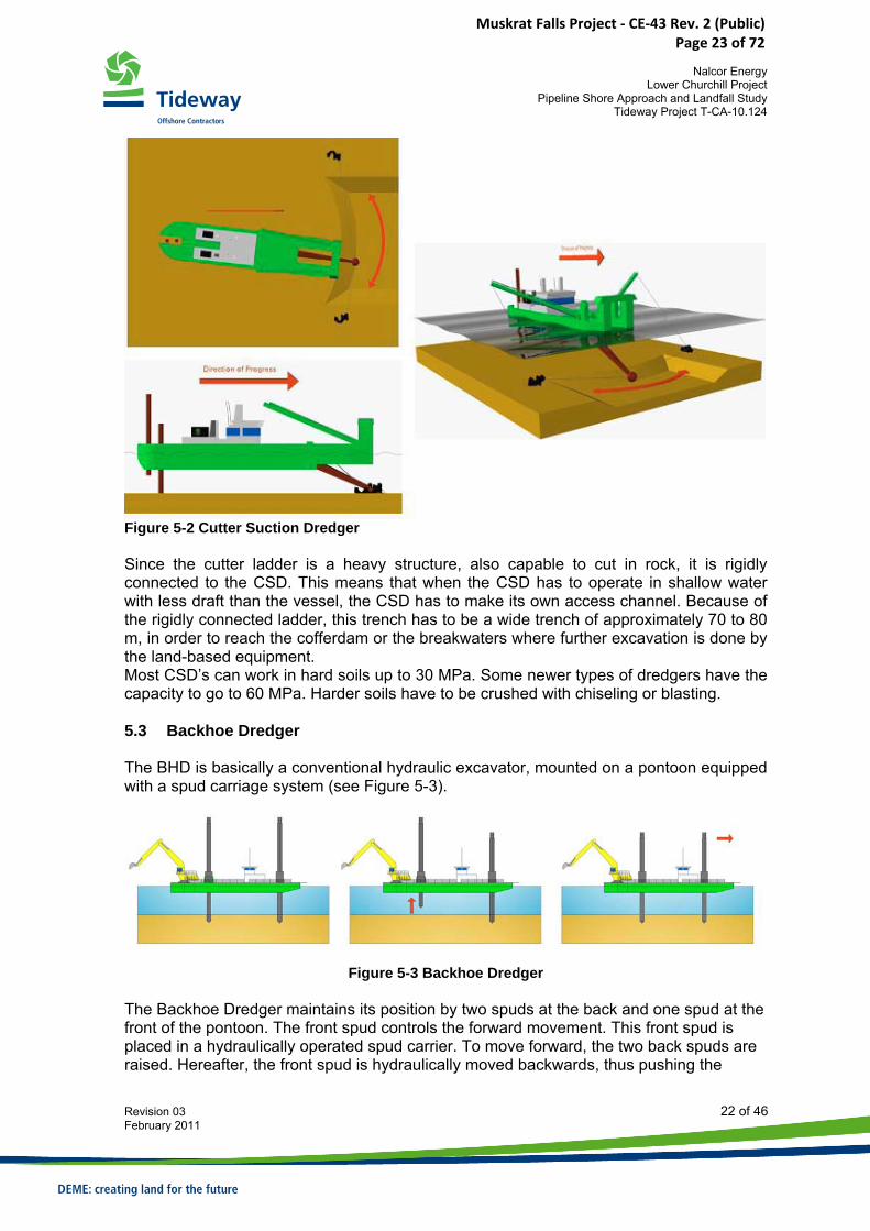
Figure 5-2 Cutter Suction Dredger Since the cutter ladder is a heavy structure, also capable to cut in rock, it is rigidly connected to the CSD. This means that when the CSD has to operate in shallow water with less draft than the vessel, the CSD has to make its own access channel. Because of the rigidly connected ladder, this trench has to be a wide trench of approximately 70 to 80 m, in order to reach the cofferdam or the breakwaters where further excavation is done by the land-based equipment. Most CSD’s can work in hard soils up to 30 MPa. Some newer types of dredgers have the capacity to go to 60 MPa. Harder soils have to be crushed with chiseling or blasting. 5.3 Backhoe Dredger The BHD is basically a conventional hydraulic excavator, mounted on a pontoon equipped with a spud carriage system (see Figure 5-3).
Figure 5-3 Backhoe Dredger
The Backhoe Dredger maintains its position by two spuds at the back and one spud at the front of the pontoon. The front spud controls the forward movement. This front spud is placed in a hydraulically operated spud carrier. To move forward, the two back spuds are raised. Hereafter, the front spud is hydraulically moved backwards, thus pushing the
Muskrat Falls Project - CE-43 Rev. 2 (Public) Page 23 of 72
Nalcor Energy
Lower Churchill Project Pipeline Shore Approach and Landfall Study
Tideway Project T-CA-10.124
Revision 03 23 of 46 February 2011
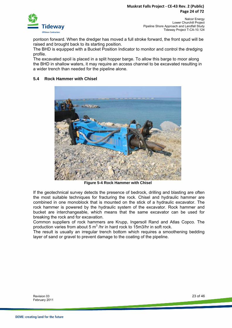
pontoon forward. When the dredger has moved a full stroke forward, the front spud will be raised and brought back to its starting position. The BHD is equipped with a Bucket Position Indicator to monitor and control the dredging profile. The excavated spoil is placed in a split hopper barge. To allow this barge to moor along the BHD in shallow waters, it may require an access channel to be excavated resulting in a wider trench than needed for the pipeline alone. 5.4 Rock Hammer with Chisel
Figure 5-4 Rock Hammer with Chisel
If the geotechnical survey detects the presence of bedrock, drilling and blasting are often the most suitable techniques for fracturing the rock. Chisel and hydraulic hammer are combined in one monoblock that is mounted on the stick of a hydraulic excavator. The rock hammer is powered by the hydraulic system of the excavator. Rock hammer and bucket are interchangeable, which means that the same excavator can be used for breaking the rock and for excavation. Common suppliers of rock hammers are Krupp, Ingersoll Rand and Atlas Copco. The production varies from about 5 m3 /hr in hard rock to 15m3/hr in soft rock. The result is usually an irregular trench bottom which requires a smoothening bedding layer of sand or gravel to prevent damage to the coating of the pipeline.
Muskrat Falls Project - CE-43 Rev. 2 (Public) Page 24 of 72
Nalcor Energy
Lower Churchill Project Pipeline Shore Approach and Landfall Study
Tideway Project T-CA-10.124
Revision 03 24 of 46 February 2011
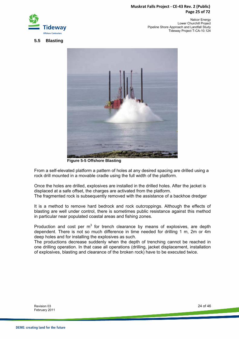
5.5 Blasting
Figure 5-5 Offshore Blasting
From a self-elevated platform a pattern of holes at any desired spacing are drilled using a rock drill mounted in a movable cradle using the full width of the platform. Once the holes are drilled, explosives are installed in the drilled holes. After the jacket is displaced at a safe offset, the charges are activated from the platform. The fragmented rock is subsequently removed with the assistance of a backhoe dredger It is a method to remove hard bedrock and rock outcroppings. Although the effects of blasting are well under control, there is sometimes public resistance against this method in particular near populated coastal areas and fishing zones. Production and cost per m3 for trench clearance by means of explosives, are depth dependent. There is not so much difference in time needed for drilling 1 m, 2m or 4m deep holes and for installing the explosives as such. The productions decrease suddenly when the depth of trenching cannot be reached in one drilling operation. In that case all operations (drilling, jacket displacement, installation of explosives, blasting and clearance of the broken rock) have to be executed twice.
Muskrat Falls Project - CE-43 Rev. 2 (Public) Page 25 of 72
Nalcor Energy
Lower Churchill Project Pipeline Shore Approach and Landfall Study
Tideway Project T-CA-10.124
Revision 03 25 of 46 February 2011
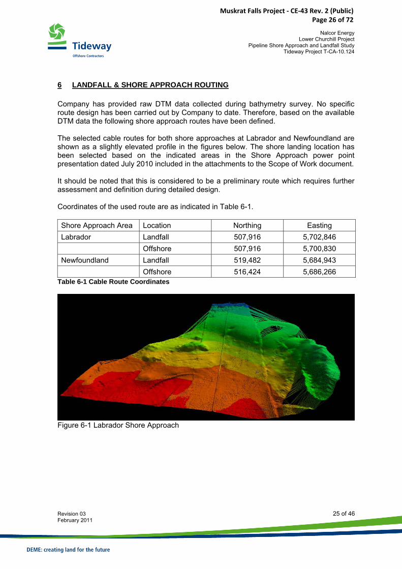
6 LANDFALL & SHORE APPROACH ROUTING Company has provided raw DTM data collected during bathymetry survey. No specific route design has been carried out by Company to date. Therefore, based on the available DTM data the following shore approach routes have been defined. The selected cable routes for both shore approaches at Labrador and Newfoundland are shown as a slightly elevated profile in the figures below. The shore landing location has been selected based on the indicated areas in the Shore Approach power point presentation dated July 2010 included in the attachments to the Scope of Work document. It should be noted that this is considered to be a preliminary route which requires further assessment and definition during detailed design. Coordinates of the used route are as indicated in Table 6-1. Shore Approach Area Location Northing Easting Labrador Landfall 507,916 5,702,846 Offshore 507,916 5,700,830 Newfoundland Landfall 519,482 5,684,943 Offshore 516,424 5,686,266
Table 6-1 Cable Route Coordinates
Figure 6-1 Labrador Shore Approach
Muskrat Falls Project - CE-43 Rev. 2 (Public) Page 26 of 72
Nalcor Energy
Lower Churchill Project Pipeline Shore Approach and Landfall Study
Tideway Project T-CA-10.124
Revision 03 26 of 46 February 2011
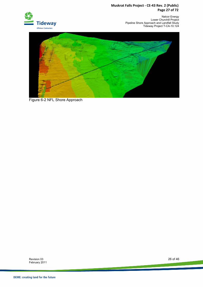
Figure 6-2 NFL Shore Approach
Muskrat Falls Project - CE-43 Rev. 2 (Public) Page 27 of 72
Nalcor Energy
Lower Churchill Project Pipeline Shore Approach and Landfall Study
Tideway Project T-CA-10.124
Revision 03 27 of 46 February 2011
7 LOWER CHURCHILL PROJECT SHORE APPROACH SCENARIO 7.1 Introduction As seen in Section 4 above, the shore approach can be carried out based on either an open excavation or a tunneling methodology. Generally speaking, the open excavation will be the most cost efficient methodology. Tunneling methods in general will be significantly more expensive when compared to open excavations. When a comparison is made between the various tunneling methods, an HDD tunnel will be lower in base cost, but has a higher risk profile when compared to a microtunnel, as failing of the drilled hole may occur during the drilling process, which will require abandonment of the HDD and require another attempt. Due to the higher cost, tunneling methods are normally considered where open excavation methodology is not considered feasible or not allowed due to restrictions in the permits. In the case of power cables the use of tunneling methods should be considered carefully as the cooling of power cable may be insufficient in tunnels, which sometimes can render this methodology as unacceptable. It has been indicated that at this stage there are no specific reasons not to adopt a standard open excavation method for the Lower Churchill project, which therefore has been adopted as the base case methodology for the study. Based on the soil conditions, it can be seen that only a few techniques are suitable for excavation of the trench as most are simply not capable of dealing with the rock. The only viable techniques are blasting and chiseling, where chiseling is characterized by small productions and therefore slow, and hence blasting will be the preferred technique for fracturing of the rock. 7.2 Onshore & Nearshore Trench Considering the soil conditions of the Strait of Belle Isle with a seabed consisting of very hard rock, installation of a cofferdam will not be feasible and a causeway will be required to excavate the nearshore section of the trench. The causeway also provides protection to the trench after excavation against sedimentation. The bedrock will be removed by blasting followed by excavation. This may be carried out by constructing the causeway over the trench area in order to provide access for the drilling rigs. After the blasting of the deeper bedrock layer, the nearshore trench is excavated using land-based equipment. The required length of the causeway is determined by the characteristics of the seabed, the foreshore profile and the draught limitations of the selected offshore equipment. A typical transition point of 2m water depth will be used.
Muskrat Falls Project - CE-43 Rev. 2 (Public) Page 28 of 72
Nalcor Energy
Lower Churchill Project Pipeline Shore Approach and Landfall Study
Tideway Project T-CA-10.124
Revision 03 28 of 46 February 2011
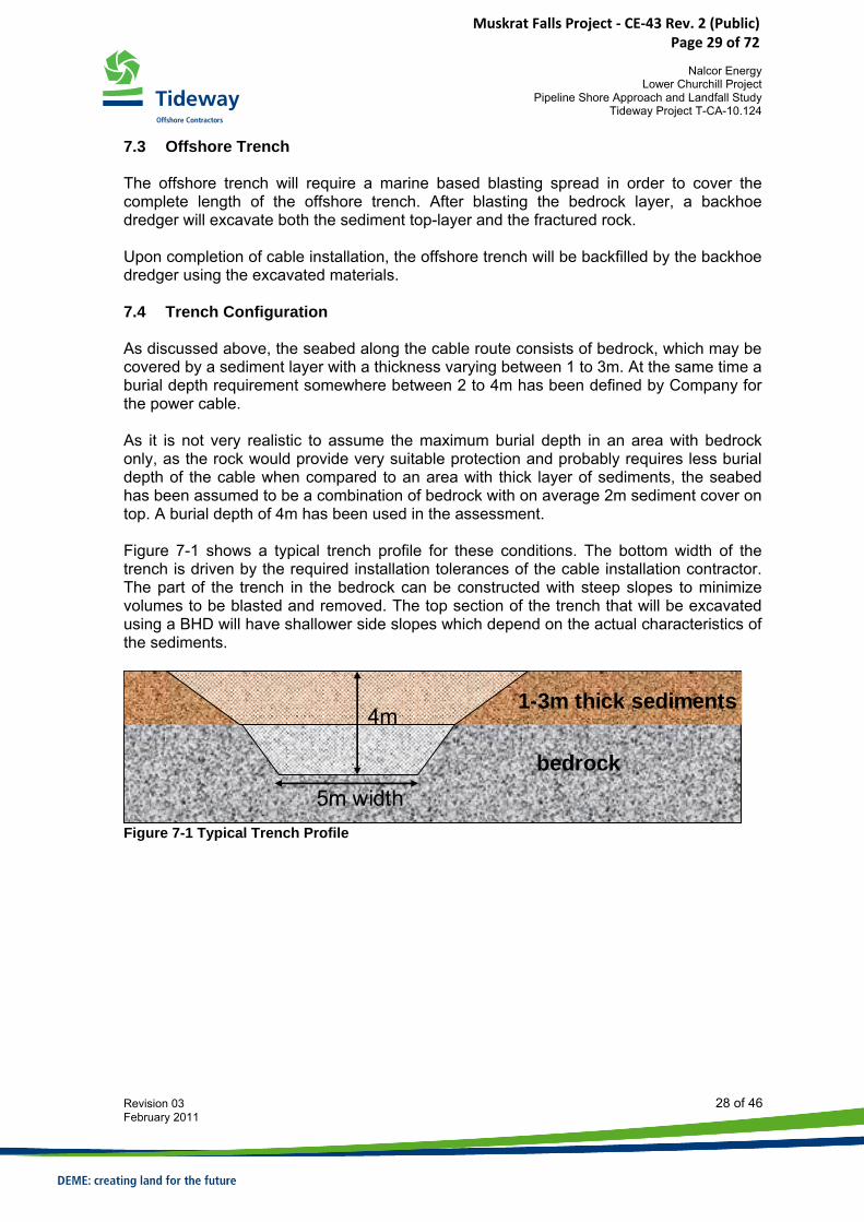
7.3 Offshore Trench The offshore trench will require a marine based blasting spread in order to cover the complete length of the offshore trench. After blasting the bedrock layer, a backhoe dredger will excavate both the sediment top-layer and the fractured rock. Upon completion of cable installation, the offshore trench will be backfilled by the backhoe dredger using the excavated materials. 7.4 Trench Configuration As discussed above, the seabed along the cable route consists of bedrock, which may be covered by a sediment layer with a thickness varying between 1 to 3m. At the same time a burial depth requirement somewhere between 2 to 4m has been defined by Company for the power cable. As it is not very realistic to assume the maximum burial depth in an area with bedrock only, as the rock would provide very suitable protection and probably requires less burial depth of the cable when compared to an area with thick layer of sediments, the seabed has been assumed to be a combination of bedrock with on average 2m sediment cover on top. A burial depth of 4m has been used in the assessment. Figure 7-1 shows a typical trench profile for these conditions. The bottom width of the trench is driven by the required installation tolerances of the cable installation contractor. The part of the trench in the bedrock can be constructed with steep slopes to minimize volumes to be blasted and removed. The top section of the trench that will be excavated using a BHD will have shallower side slopes which depend on the actual characteristics of the sediments.
1-3m thick sediments
bedrock
4m
5m width
Figure 7-1 Typical Trench Profile
Muskrat Falls Project - CE-43 Rev. 2 (Public) Page 29 of 72
Nalcor Energy
Lower Churchill Project Pipeline Shore Approach and Landfall Study
Tideway Project T-CA-10.124
Revision 03 29 of 46 February 2011
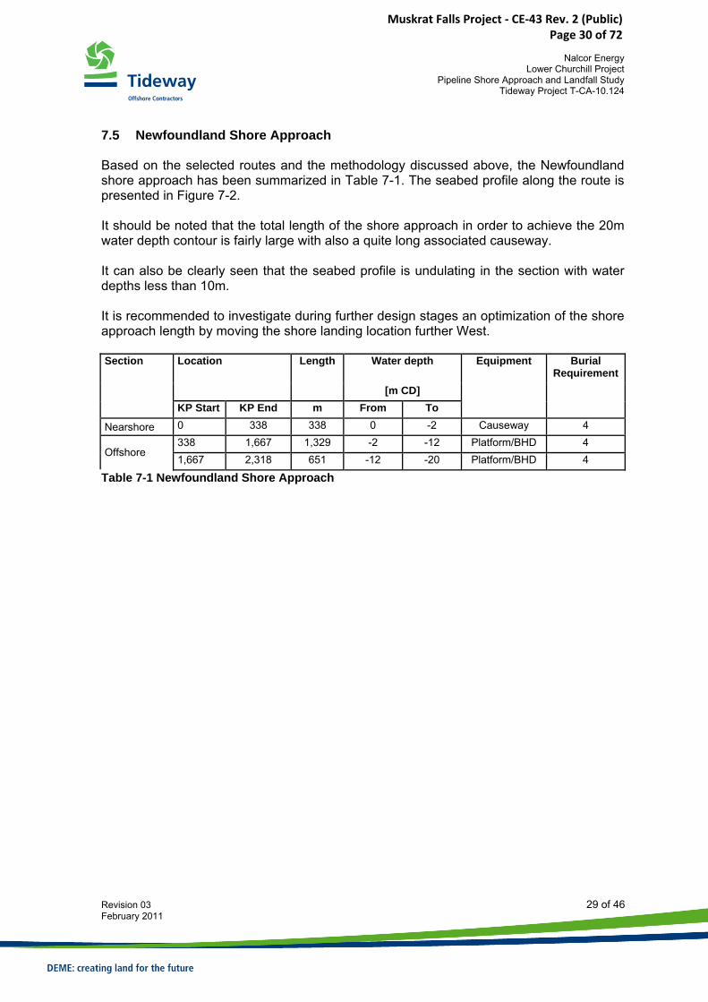
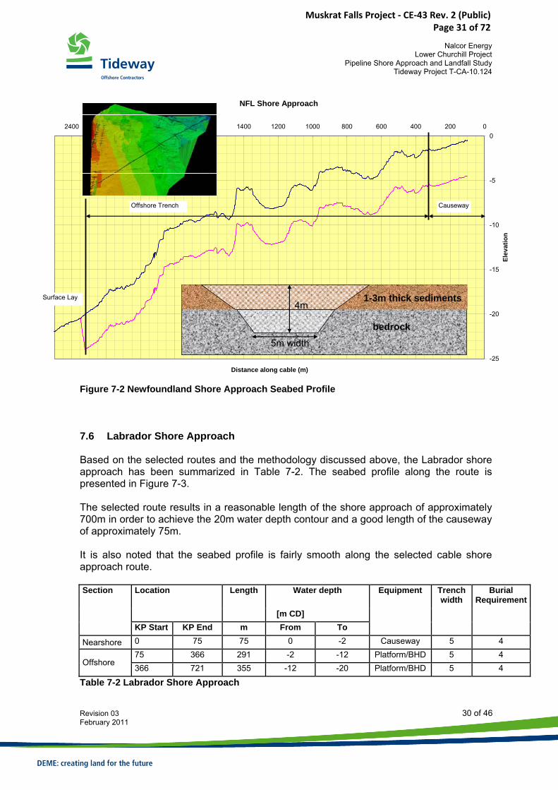
7.5 Newfoundland Shore Approach Based on the selected routes and the methodology discussed above, the Newfoundland shore approach has been summarized in Table 7-1. The seabed profile along the route is presented in Figure 7-2. It should be noted that the total length of the shore approach in order to achieve the 20m water depth contour is fairly large with also a quite long associated causeway. It can also be clearly seen that the seabed profile is undulating in the section with water depths less than 10m. It is recommended to investigate during further design stages an optimization of the shore approach length by moving the shore landing location further West.
Water depth Section Location Length
[m CD] KP Start KP End m From To
Equipment Burial Requirement
Nearshore 0 338 338 0 -2 Causeway 4 338 1,667 1,329 -2 -12 Platform/BHD 4
Offshore 1,667 2,318 651 -12 -20 Platform/BHD 4
Table 7-1 Newfoundland Shore Approach
Muskrat Falls Project - CE-43 Rev. 2 (Public) Page 30 of 72
Nalcor Energy
Lower Churchill Project Pipeline Shore Approach and Landfall Study
Tideway Project T-CA-10.124
Revision 03 30 of 46 February 2011
NFL Shore Approach
-25
-20
-15
-10
-5
0020040060080010001200140016001800200022002400
Distance along cable (m)
Elev
atio
n
Offshore Trench
Surface Lay
Causeway
1-3m thick sediments
bedrock
4m
5m width
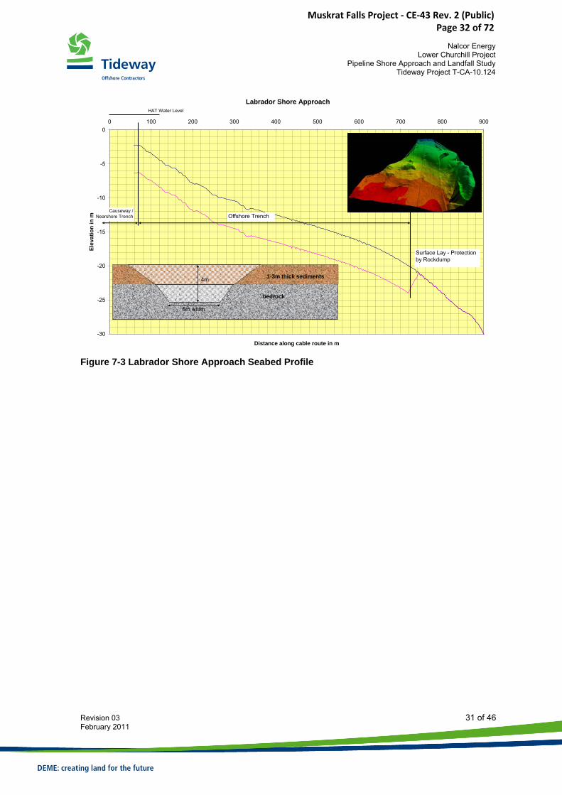
Figure 7-2 Newfoundland Shore Approach Seabed Profile 7.6 Labrador Shore Approach Based on the selected routes and the methodology discussed above, the Labrador shore approach has been summarized in Table 7-2. The seabed profile along the route is presented in Figure 7-3. The selected route results in a reasonable length of the shore approach of approximately 700m in order to achieve the 20m water depth contour and a good length of the causeway of approximately 75m. It is also noted that the seabed profile is fairly smooth along the selected cable shore approach route.
Water depth
Section Location Length
[m CD] KP Start KP End m From To
Equipment Trench width
Burial Requirement
Nearshore 0 75 75 0 -2 Causeway 5 4 75 366 291 -2 -12 Platform/BHD 5 4
Offshore 366 721 355 -12 -20 Platform/BHD 5 4
Table 7-2 Labrador Shore Approach
Muskrat Falls Project - CE-43 Rev. 2 (Public) Page 31 of 72
Nalcor Energy
Lower Churchill Project Pipeline Shore Approach and Landfall Study
Tideway Project T-CA-10.124
Revision 03 31 of 46 February 2011
Labrador Shore Approach
-30
-25
-20
-15
-10
-5
00 100 200 300 400 500 600 700 800 900
Distance along cable route in m
Elev
atio
n in
m
Surface Lay - Protection by Rockdump
Offshore TrenchCauseway /
Nearshore Trench
bedrock
4m
5m width
HAT Water Level
1-3m thick sediments
Figure 7-3 Labrador Shore Approach Seabed Profile
Muskrat Falls Project - CE-43 Rev. 2 (Public) Page 32 of 72
Nalcor Energy
Lower Churchill Project Pipeline Shore Approach and Landfall Study
Tideway Project T-CA-10.124
Revision 03 32 of 46 February 2011
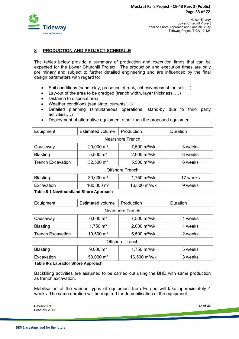
8 PRODUCTION AND PROJECT SCHEDULE The tables below provide a summary of production and execution times that can be expected for the Lower Churchill Project. The production and execution times are only preliminary and subject to further detailed engineering and are influenced by the final design parameters with regard to:
• Soil conditions (sand, clay, presence of rock, cohesiveness of the soil,…) • Lay-out of the area to be dredged (trench width, layer thickness, …) • Distance to disposal area • Weather conditions (sea state, currents,…) • Detailed planning (simultaneous operations, stand-by due to third party
activities,…) • Deployment of alternative equipment other than the proposed equipment
Equipment Estimated volume Production Duration
Nearshore Trench
Causeway 20,000 m³ 7,500 m³/wk 3 weeks
Blasting 5,500 m³ 2,000 m³/wk 3 weeks
Trench Excavation 32,500 m³ 5,500 m³/wk 6 weeks
Offshore Trench
Blasting 30,000 m³ 1,750 m³/wk 17 weeks
Excavation 160,000 m³ 16,500 m³/wk 9 weeks Table 8-1 Newfoundland Shore Approach Equipment Estimated volume Production Duration
Nearshore Trench
Causeway 6,000 m³ 7,500 m³/wk 1 weeks
Blasting 1,750 m³ 2,000 m³/wk 1 weeks
Trench Excavation 10,500 m³ 5,500 m³/wk 2 weeks
Offshore Trench
Blasting 9,000 m³ 1,750 m³/wk 5 weeks
Excavation 50,000 m³ 16,500 m³/wk 3 weeks Table 8-2 Labrador Shore Approach Backfilling activities are assumed to be carried out using the BHD with same production as trench excavation. Mobilisation of the various types of equipment from Europe will take approximately 4 weeks. The same duration will be required for demobilisation of the equipment.
Muskrat Falls Project - CE-43 Rev. 2 (Public) Page 33 of 72
Nalcor Energy
Lower Churchill Project Pipeline Shore Approach and Landfall Study
Tideway Project T-CA-10.124
Revision 03 33 of 46 February 2011
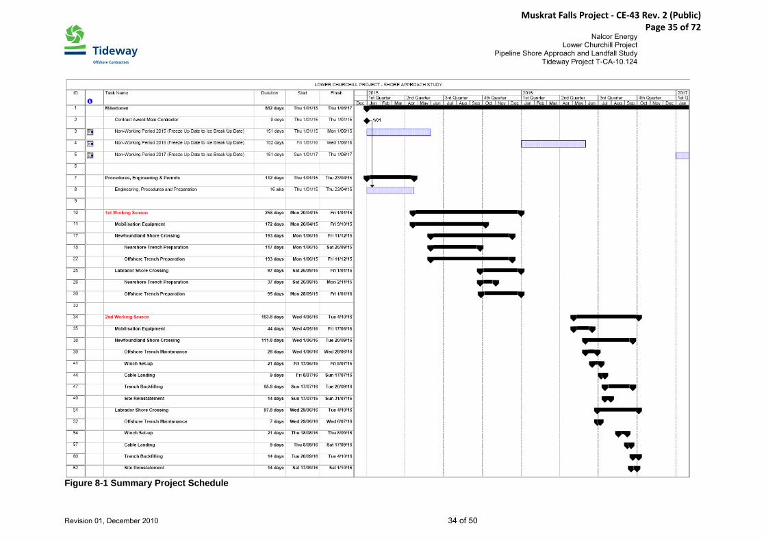
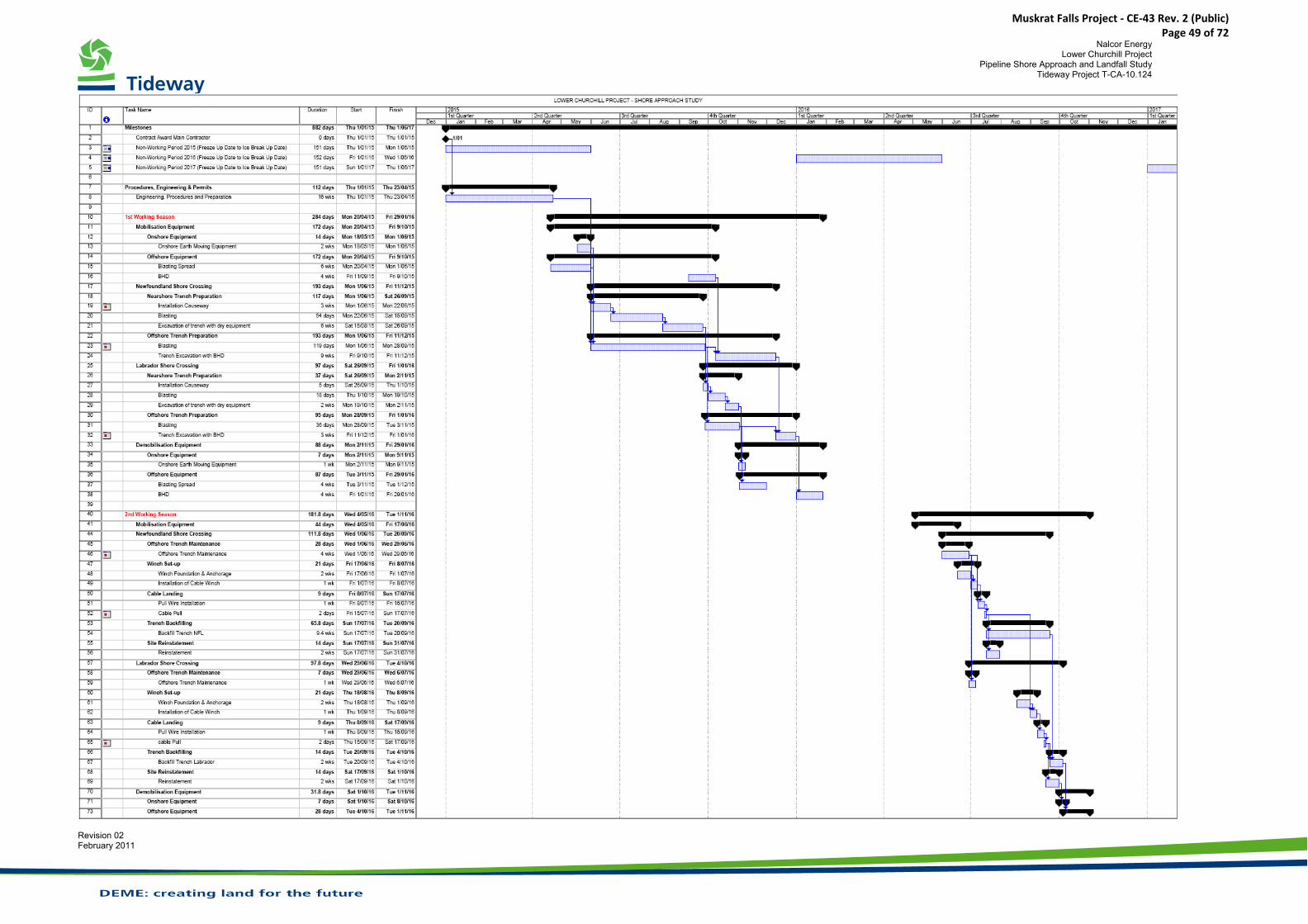
Figure 8-1 presents an indicative summary schedule of the project activities. The complete schedule is included in Appendix A. It should be noted that the non-working periods defined by the ice break-up and freeze-up dates may not actually apply to all construction activities. Onshore activities, such as preparations of the landfall sites, winch set-up etc, may also be possible to carry out before ice break-up dates. This may have a favourable impact to the schedule presented below.
Muskrat Falls Project - CE-43 Rev. 2 (Public) Page 34 of 72
Nalcor Energy Lower Churchill Project
Pipeline Shore Approach and Landfall Study Tideway Project T-CA-10.124
Revision 01, December 2010 34 of 50
Figure 8-1 Summary Project Schedule
Muskrat Falls Project - CE-43 Rev. 2 (Public) Page 35 of 72
Nalcor Energy
Lower Churchill Project Pipeline Shore Approach and Landfall Study
Tideway Project T-CA-10.124
Revision 02 35 of 46 February 2011
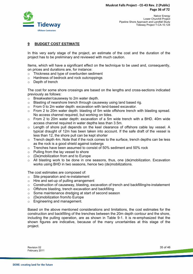
9 BUDGET COST ESTIMATE In this very early stage of the project, an estimate of the cost and the duration of the project has to be preliminary and reviewed with much caution. Items, which will have a significant effect on the technique to be used and, consequently, on prices and durations are, for instance: o Thickness and type of overburden sediment o Hardness of bedrock and rock outcroppings o Depth of trench The cost for some shore crossings are based on the lengths and cross-sections indicated previously as follows: o Breakwater/causeway to 2m water depth. o Blasting of nearshore trench through causeway using land based rig. o From 0 to 2m water depth: excavation with land-based excavator. o From 2 to 20m water depth: blasting of 5m wide offshore trench with blasting spread.
No access channel required, but working on tides. o From 2 to 20m water depth: excavation of a 5m wide trench with a BHD. 40m wide
access channel required in water depths less than 3.5m. o Length of shore pull depends on the keel clearance of offshore cable lay vessel. A
typical draught of 12m has been taken into account. If the safe draft of the vessel is less than 12, the shore pull can be kept shorter
o Trench depth 4m. Note that if the rock comes to the surface, trench depths can be less as the rock is a good shield against icebergs
o Trenches have been assumed to consist of 50% sediment and 50% rock o Pulling from the lay vessel to shore o (De)mobilization from and to Europe o All blasting work to be done in one seasons, thus, one (de)mobilization. Excavation
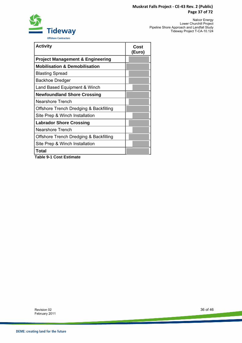
works using BHD in two seasons, hence two (de)mobilizations. The cost estimates are composed of: o Site preparation and re-instatement o Hire and set-up of pulling arrangement o Construction of causeway, blasting, excavation of trench and backfilling/re-instatement o Offshore blasting, trench excavation and backfilling o Some maintenance dredging at start of second season o (De)mobilization from/to Europe o Engineering and management. Based on the above mentioned considerations and limitations, the cost estimates for the construction and backfilling of the trenches between the 20m depth contour and the shore, including the pulling operation, are as shown in Table 9-1. It is re-emphasized that the shown figures are indicative, because of the many uncertainties at this stage of the project.
Muskrat Falls Project - CE-43 Rev. 2 (Public) Page 36 of 72
Nalcor Energy
Lower Churchill Project Pipeline Shore Approach and Landfall Study
Tideway Project T-CA-10.124
Revision 02 36 of 46 February 2011
Activity
Cost (Euro)
Project Management & Engineering Mobilisation & Demobilisation Blasting Spread Backhoe Dredger Land Based Equipment & Winch Newfoundland Shore Crossing Nearshore Trench Offshore Trench Dredging & Backfilling Site Prep & Winch Installation Labrador Shore Crossing Nearshore Trench Offshore Trench Dredging & Backfilling Site Prep & Winch Installation Total Table 9-1 Cost Estimate
Muskrat Falls Project - CE-43 Rev. 2 (Public) Page 37 of 72
Nalcor Energy
Lower Churchill Project Pipeline Shore Approach and Landfall Study
Tideway Project T-CA-10.124
Revision 02 37 of 46 February 2011
10 METHOD STATEMENT In accordance with the study scope, the following items are discussed:
• Site Installation • Construction of causeway • Creating nearshore and offshore trench by blasting over a length of 750 and
2350m for the Labrador and Newfoundland shore approaches, respectively • Excavation of the trenches at both landfalls to an assumed depth of 4m • Installation of winchpad areas • Cable pull-in operations • Backfilling of the trenches • Reinstate sites
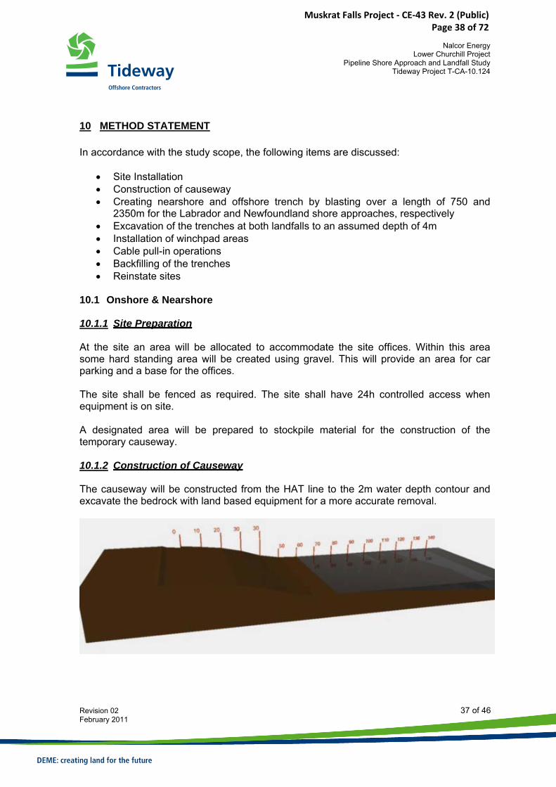
10.1 Onshore & Nearshore 10.1.1 Site Preparation At the site an area will be allocated to accommodate the site offices. Within this area some hard standing area will be created using gravel. This will provide an area for car parking and a base for the offices. The site shall be fenced as required. The site shall have 24h controlled access when equipment is on site. A designated area will be prepared to stockpile material for the construction of the temporary causeway. 10.1.2 Construction of Causeway The causeway will be constructed from the HAT line to the 2m water depth contour and excavate the bedrock with land based equipment for a more accurate removal.
Muskrat Falls Project - CE-43 Rev. 2 (Public) Page 38 of 72
Nalcor Energy
Lower Churchill Project Pipeline Shore Approach and Landfall Study
Tideway Project T-CA-10.124
Revision 02 38 of 46 February 2011
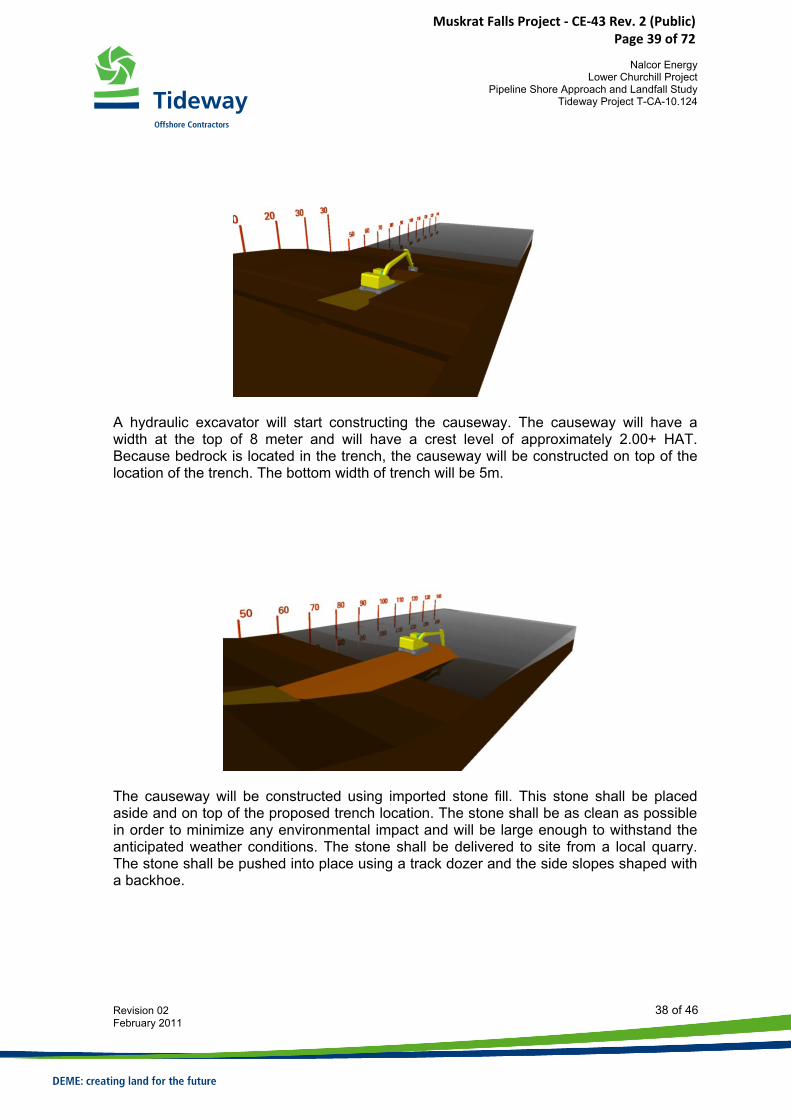
A hydraulic excavator will start constructing the causeway. The causeway will have a width at the top of 8 meter and will have a crest level of approximately 2.00+ HAT. Because bedrock is located in the trench, the causeway will be constructed on top of the location of the trench. The bottom width of trench will be 5m.
The causeway will be constructed using imported stone fill. This stone shall be placed aside and on top of the proposed trench location. The stone shall be as clean as possible in order to minimize any environmental impact and will be large enough to withstand the anticipated weather conditions. The stone shall be delivered to site from a local quarry. The stone shall be pushed into place using a track dozer and the side slopes shaped with a backhoe.
Muskrat Falls Project - CE-43 Rev. 2 (Public) Page 39 of 72
Nalcor Energy
Lower Churchill Project Pipeline Shore Approach and Landfall Study
Tideway Project T-CA-10.124
Revision 02 39 of 46 February 2011
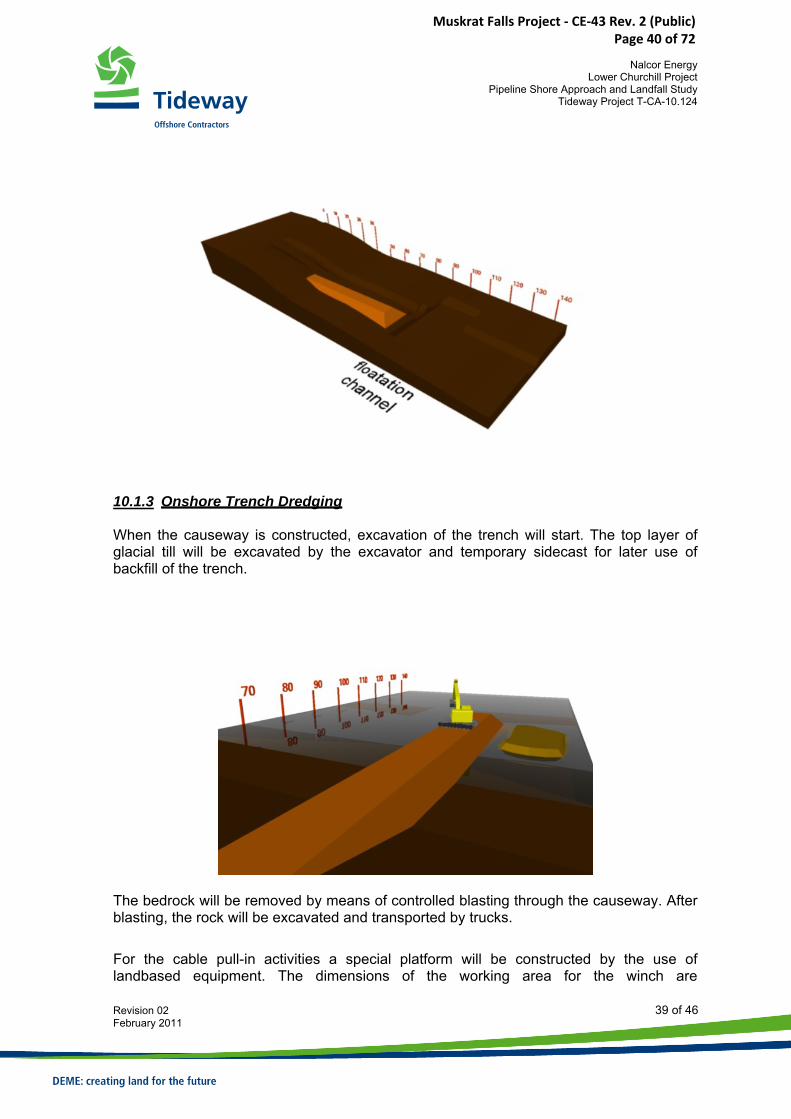
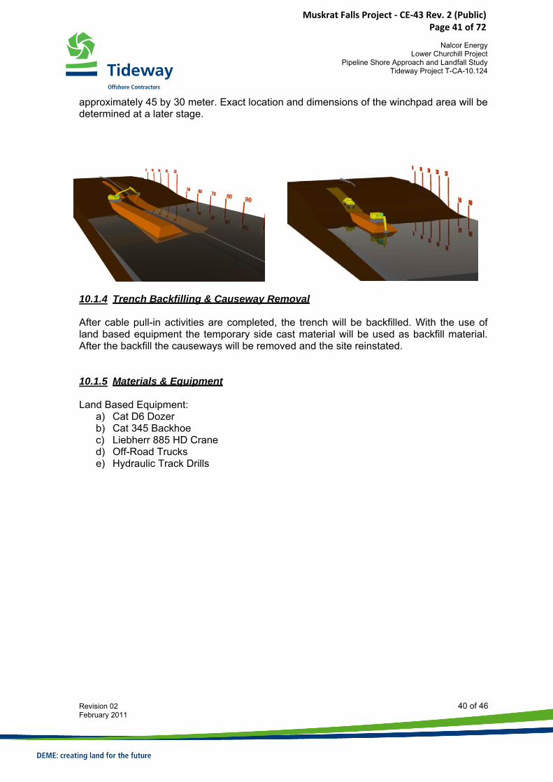
10.1.3 Onshore Trench Dredging When the causeway is constructed, excavation of the trench will start. The top layer of glacial till will be excavated by the excavator and temporary sidecast for later use of backfill of the trench.
The bedrock will be removed by means of controlled blasting through the causeway. After blasting, the rock will be excavated and transported by trucks.
For the cable pull-in activities a special platform will be constructed by the use of landbased equipment. The dimensions of the working area for the winch are
Muskrat Falls Project - CE-43 Rev. 2 (Public) Page 40 of 72
Nalcor Energy
Lower Churchill Project Pipeline Shore Approach and Landfall Study
Tideway Project T-CA-10.124
Revision 02 40 of 46 February 2011
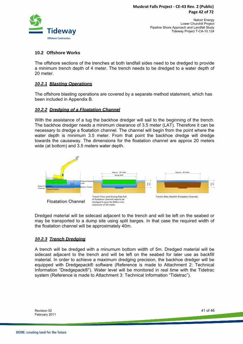
approximately 45 by 30 meter. Exact location and dimensions of the winchpad area will be determined at a later stage.
10.1.4 Trench Backfilling & Causeway Removal After cable pull-in activities are completed, the trench will be backfilled. With the use of land based equipment the temporary side cast material will be used as backfill material. After the backfill the causeways will be removed and the site reinstated. 10.1.5 Materials & Equipment Land Based Equipment:
a) Cat D6 Dozer b) Cat 345 Backhoe c) Liebherr 885 HD Crane d) Off-Road Trucks e) Hydraulic Track Drills
Muskrat Falls Project - CE-43 Rev. 2 (Public) Page 41 of 72
Nalcor Energy
Lower Churchill Project Pipeline Shore Approach and Landfall Study
Tideway Project T-CA-10.124
Revision 02 41 of 46 February 2011
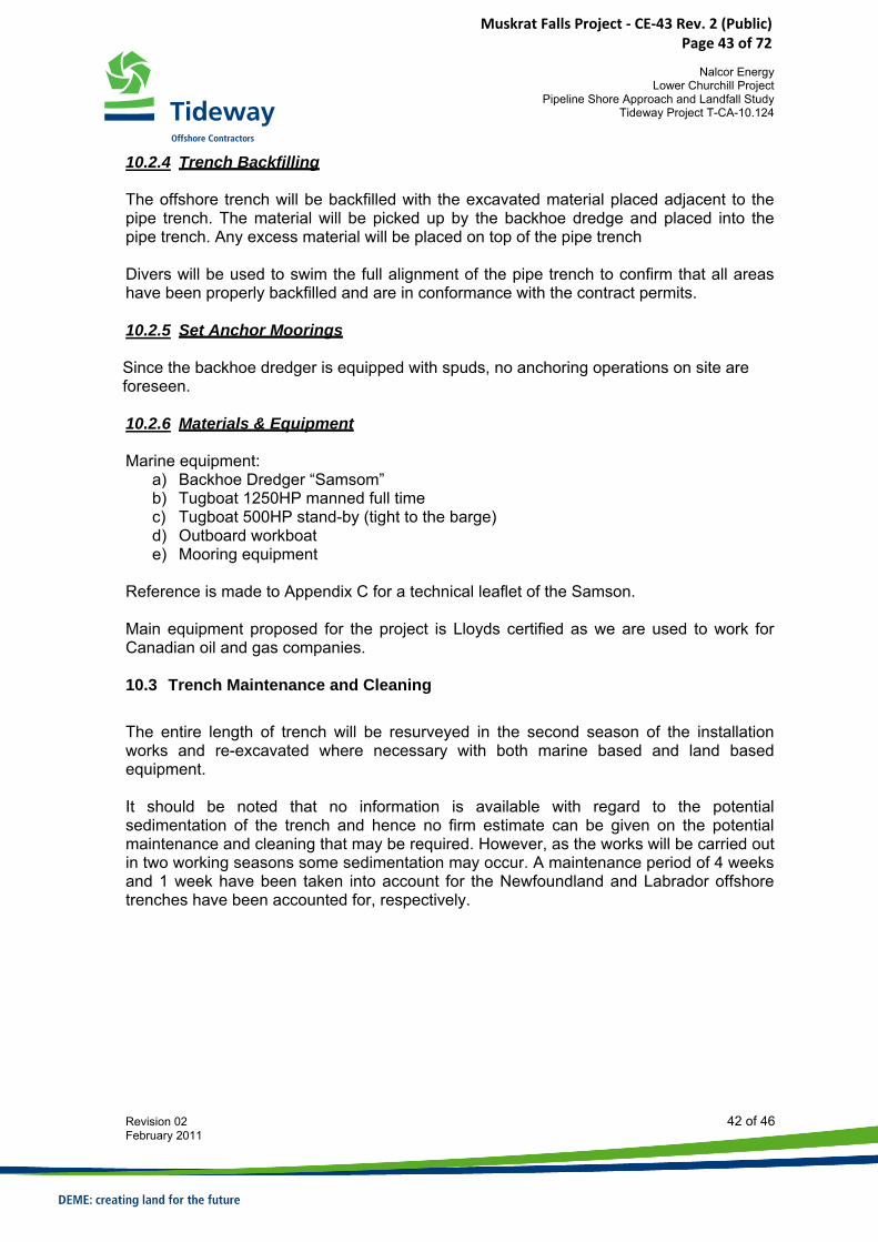
10.2 Offshore Works The offshore sections of the trenches at both landfall sides need to be dredged to provide a minimum trench depth of 4 meter. The trench needs to be dredged to a water depth of 20 meter. 10.2.1 Blasting Operations The offshore blasting operations are covered by a separate method statement, which has been included in Appendix B. 10.2.2 Dredging of a Floatation Channel With the assistance of a tug the backhoe dredger will sail to the beginning of the trench. The backhoe dredger needs a minimum clearance of 3.5 meter (LAT). Therefore it can be necessary to dredge a floatation channel. The channel will begin from the point where the water depth is minimum 3.5 meter. From that point the backhoe dredge will dredge towards the causeway. The dimensions for the floatation channel are approx 20 meters wide (at bottom) and 3.5 meters water depth.
Dredged material will be sidecast adjacent to the trench and will be left on the seabed or may be transported to a dump site using split barges. In that case the required width of the floatation channel will be approximately 40m. 10.2.3 Trench Dredging A trench will be dredged with a minumum bottom width of 5m. Dredged material will be sidecast adjacent to the trench and will be left on the seabed for later use as backfill material. In order to achieve a maximum dredging precision, the backhoe dredger will be equipped with Dredgepack® software (Reference is made to Attachment 2: Technical Information “Dredgepack®”). Water level will be monitored in real time with the Tidetrac system (Reference is made to Attachment 3: Technical Information “Tidetrac”).
Muskrat Falls Project - CE-43 Rev. 2 (Public) Page 42 of 72
Nalcor Energy
Lower Churchill Project Pipeline Shore Approach and Landfall Study
Tideway Project T-CA-10.124
Revision 02 42 of 46 February 2011
10.2.4 Trench Backfilling The offshore trench will be backfilled with the excavated material placed adjacent to the pipe trench. The material will be picked up by the backhoe dredge and placed into the pipe trench. Any excess material will be placed on top of the pipe trench Divers will be used to swim the full alignment of the pipe trench to confirm that all areas have been properly backfilled and are in conformance with the contract permits. 10.2.5 Set Anchor Moorings Since the backhoe dredger is equipped with spuds, no anchoring operations on site are foreseen. 10.2.6 Materials & Equipment Marine equipment:
a) Backhoe Dredger “Samsom” b) Tugboat 1250HP manned full time c) Tugboat 500HP stand-by (tight to the barge) d) Outboard workboat e) Mooring equipment
Reference is made to Appendix C for a technical leaflet of the Samson. Main equipment proposed for the project is Lloyds certified as we are used to work for Canadian oil and gas companies. 10.3 Trench Maintenance and Cleaning The entire length of trench will be resurveyed in the second season of the installation works and re-excavated where necessary with both marine based and land based equipment. It should be noted that no information is available with regard to the potential sedimentation of the trench and hence no firm estimate can be given on the potential maintenance and cleaning that may be required. However, as the works will be carried out in two working seasons some sedimentation may occur. A maintenance period of 4 weeks and 1 week have been taken into account for the Newfoundland and Labrador offshore trenches have been accounted for, respectively.
Muskrat Falls Project - CE-43 Rev. 2 (Public) Page 43 of 72
Nalcor Energy
Lower Churchill Project Pipeline Shore Approach and Landfall Study
Tideway Project T-CA-10.124
Revision 02 43 of 46 February 2011
10.4 Cable pull-in 10.4.1 General All equipment required for the pulling of the cable will be inspected and tested prior to installation on site. The pulling arrangement will in principle consists of following elements: 10.4.2 Onshore winch spread for the pull ashore; Pulling arrangement onshore will in principle consists of following elements:
• 1 no of approximately 50 tonnes constant tension pulling winch • 1 no of pull-in wire length 2,300m • 1 no of pull-in wire length 750m • 1 no of powered reel winders • 1 no of power packs to operate winch and reel winders • 1 no of transport reels • 1 no control cabin and spare parts container onshore
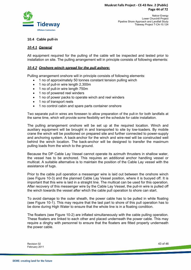
Two separate pull-in wires are foreseen to allow preparation of the pull-in for both landfalls at the same time, which will provide some flexibility wrt the schedule for cable installation. The pulling arrangement onshore will be set up at the required location. Winch and auxiliary equipment will be brought in and transported to site by low-loaders. By mobile crane the winch will be positioned on prepared site and further connected to power-supply and anchoring system. A back-anchor for the winch and wire-reel will be constructed well behind the winch location. The back-anchor will be designed to transfer the maximum pulling loads from the winch to the ground. Because the DP Cable Lay Vessel cannot operate its azimuth thrusters in shallow water, the vessel has to be anchored. This requires an additional anchor handling vessel or multicat. A suitable alternative is to maintain the position of the Cable Lay vessel with the assistance of tugs. Prior to the cable pull operation a messenger wire is laid out between the onshore winch (see Figure 10-3) and the planned Cable Lay Vessel position, where it is buoyed off. It is important that this wire is laid in a straight line. The multicat can be used for this operation. After recovery of this messenger wire by the Cable Lay Vessel, the pull-in wire is pulled off the winch towards the vessel after which the cable pull operation to shore can start. To avoid damage to the outer sheath, the power cable has to be pulled in while floating (see Figure 10-1). This may require that the last part to shore of this pull operation has to be done during High Water to ensure that the whole line is in a floating condition. The floaters (see Figure 10-2) are inflated simultaneously with the cable pulling operation. These floaters are linked to each other and placed underneath the power cable. This may require a dinghy with personnel to ensure that the floaters are fitted properly underneath the power cable.
Muskrat Falls Project - CE-43 Rev. 2 (Public) Page 44 of 72
Nalcor Energy
Lower Churchill Project Pipeline Shore Approach and Landfall Study
Tideway Project T-CA-10.124
Revision 02 44 of 46 February 2011
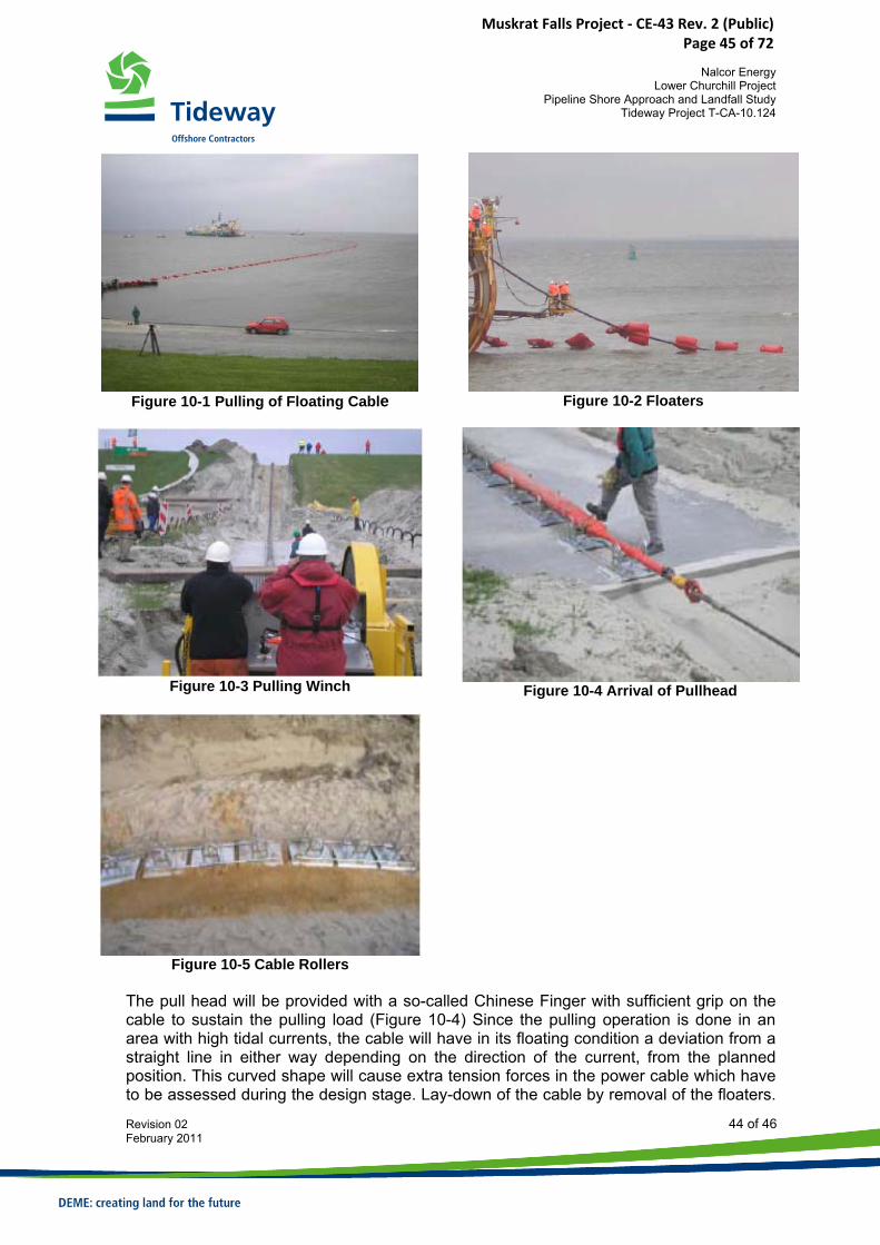
Figure 10-1 Pulling of Floating Cable
Figure 10-2 Floaters
Figure 10-3 Pulling Winch
Figure 10-4 Arrival of Pullhead
Figure 10-5 Cable Rollers
The pull head will be provided with a so-called Chinese Finger with sufficient grip on the cable to sustain the pulling load (Figure 10-4) Since the pulling operation is done in an area with high tidal currents, the cable will have in its floating condition a deviation from a straight line in either way depending on the direction of the current, from the planned position. This curved shape will cause extra tension forces in the power cable which have to be assessed during the design stage. Lay-down of the cable by removal of the floaters.
Muskrat Falls Project - CE-43 Rev. 2 (Public) Page 45 of 72

Nalcor Energy
Lower Churchill Project Pipeline Shore Approach and Landfall Study
Tideway Project T-CA-10.124
Revision 02 45 of 46 February 2011
(deflating of one wing will force the floater to break away from under the cable) has to be done during a slack tide period. If needed, the last section of the pull operation can be done over rollers placed on the beach (see Figure 10-5). When the pullhead has reached the target area, this cable end has to be secured. After cable installation the trench will be backfilled. 10.4.3 Materials & Equipment Land based equipment:
a) Cat D6 Dozer b) Cat 345 Backhoe c) Liebherr 885HD Crane d) John Deere Off-Road Trucks e) Cable Pull Winch f) Rubber Tire Loader
10.5 Survey operations The survey activities include a number of different surveys. Although the procedures for the various surveys differ in detail, the same equipment and reporting are typically used for all survey activities. Below follows a summary of the scheduled hydrographical surveys:
• Pre-dredging survey; before commencement of any work • Post-dredging / pre-installation survey; upon completion of the trench and prior to
pipeline installation • Intermediate survey after pull-in wire installation • Post-installation survey; upon completion of pipeline installation • As-built survey; upon completion of the trench backfilling works.
Regular intermediate surveys will be carried out in order to monitor progress and workmanship.
Muskrat Falls Project - CE-43 Rev. 2 (Public) Page 46 of 72

Nalcor Energy
Lower Churchill Project Pipeline Shore Approach and Landfall Study
Tideway Project T-CA-10.124
Revision 02 46 of 46 February 2011
11 REFERENCES 1. RFP, Scope of Work, Nalcor Energy
12 APPENDICES Appendix A Schedule Appendix B Method Statement Blasting Appendix C Leaflet BHD Samson
Muskrat Falls Project - CE-43 Rev. 2 (Public) Page 47 of 72
Nalcor Energy Lower Churchill Project
Pipeline Shore Approach and Landfall Study Tideway Project T-CA-10.124
Revision 02 February 2011
APPENDIX A
SCHEDULE
Muskrat Falls Project - CE-43 Rev. 2 (Public) Page 48 of 72
Nalcor Energy Lower Churchill Project
Pipeline Shore Approach and Landfall Study Tideway Project T-CA-10.124
Revision 02 February 2011
Muskrat Falls Project - CE-43 Rev. 2 (Public) Page 49 of 72
Nalcor Energy
Lower Churchill Project Pipeline Shore Approach and Landfall Study
Tideway Project T-CA-10.124
Revision 02 February 2011
APPENDIX B
METHOD STATEMENT BLASTING
Muskrat Falls Project - CE-43 Rev. 2 (Public) Page 50 of 72
Doc : MST‐001
Rev : 0
Page : 1 of 19
Date : 19/11/2010
General Method Statement Offshore Drilling and Blasting with Cartridges
Haven 1025 • Scheldedijk 30 • B‐2070 Zwijndrecht • Belgium
Tel +32 3 250 53 12 • Fax +32 3 250 55 41
Method Statement Offshore Drilling and Blasting
GeoSea document treatment & approval
Action Name Function Signature Date
Author Kevin Van de Velde Project Engineer 9/12/2010
Check Nico Coppens Manager Tender Department 9/12/2010
Approval Jan Jacobs Business Unit Manager 9/12/2010
Muskrat Falls Project - CE-43 Rev. 2 (Public) Page 51 of 72
Doc : MST‐001
Rev : 0
Page : 2 of 19
Date : 19/11/2010
General Method Statement Offshore Drilling and Blasting with Cartridges
Haven 1025 • Scheldedijk 30 • B‐2070 Zwijndrecht • Belgium
Tel +32 3 250 53 12 • Fax +32 3 250 55 41
Name Signature
Date
Code 1 □ Approved. Work may start and proceed
Code 2 □ Approved with minor comments.
Work may start and proceed subject to
Incorporation of these minor comments
Reviewed by
Code 3 □ Revise and Resubmit.
Work may not start to proceed
Code 4 □ For information only.
Approval not required
Approved by
Code 5 ■ For Tender
Revision Status
Rev Date Issue Purpose Issued by Checked by Approved by
0 9/12/2010 For Tender KEV NCO JJC
Muskrat Falls Project - CE-43 Rev. 2 (Public) Page 52 of 72
Doc : MST‐001
Rev : 0
Page : 3 of 19
Date : 19/11/2010
General Method Statement Offshore Drilling and Blasting with Cartridges
Haven 1025 • Scheldedijk 30 • B‐2070 Zwijndrecht • Belgium
Tel +32 3 250 53 12 • Fax +32 3 250 55 41
TABLE OF CONTENTS 1 INTRODUCTION .............................................................................................................................................. 4 2 DEFINITIONS................................................................................................................................................... 4 3 EQUIPMENT.................................................................................................................................................... 5
3.1 DRILL VESSEL ....................................................................................................................................................... 5 3.1.1 Jack Up........................................................................................................................................................ 5 3.1.2 Pontoon....................................................................................................................................................... 5
4 EXPLOSIVE MATERIALS ................................................................................................................................... 6 4.1 INTRODUCTION .................................................................................................................................................... 6 4.2 BLASTING SERVICES ............................................................................................................................................... 6 4.3 TRANSPORT OF EXPLOSIVE MATERIALS AND EXPLOSIVE ACCESSORIES ............................................................................... 7
5 WORK METHOD.............................................................................................................................................. 8 5.1 GENERAL: POSITIONING BY ANCHORS ....................................................................................................................... 8 5.2 CONSTRUCTION PLAN............................................................................................................................................ 9 5.3 TYPICAL SEQUENCE OF DRILLING AND BLASTING WITH CARTRIDGE EXPLOSIVES ................................................................. 10
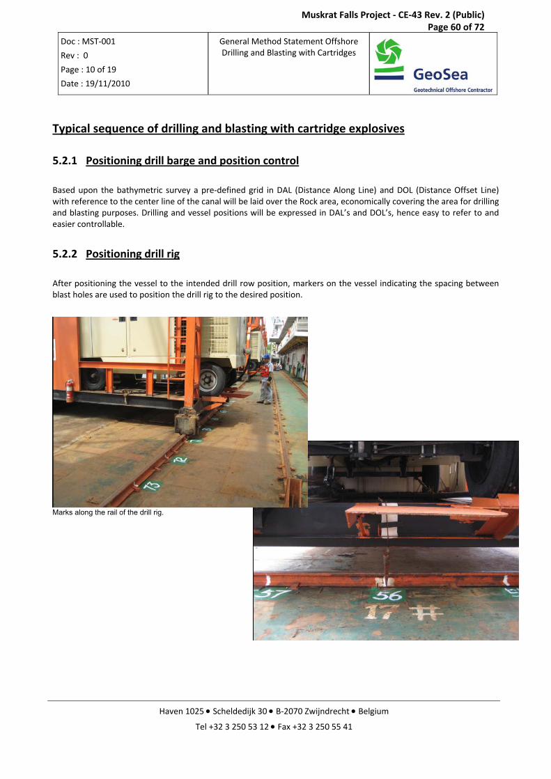
5.3.1 Positioning drill barge and position control .............................................................................................. 10 5.3.2 Positioning drill rig .................................................................................................................................... 10 5.3.3 Drilling and Loading sequence .................................................................................................................. 11 5.3.4 Blasting operation and Communication ................................................................................................... 14
6 MEASUREMENTS AND REPORTING DURING DRILLING, BLASTING AND DURING AND AFTER BLASTING.......... 15 7 QUALITY ASSURANCE & QUALITY CONTROL .................................................................................................. 16 8 HSE............................................................................................................................................................... 17
Muskrat Falls Project - CE-43 Rev. 2 (Public) Page 53 of 72
Doc : MST‐001
Rev : 0
Page : 4 of 19
Date : 19/11/2010
General Method Statement Offshore Drilling and Blasting with Cartridges
Haven 1025 • Scheldedijk 30 • B‐2070 Zwijndrecht • Belgium
Tel +32 3 250 53 12 • Fax +32 3 250 55 41
1 Introduction
The present document describes the work method for the removal of rock layers by controlled drilling and blasting for subsequent removal and disposal of the blasted materials at an approved disposal site.
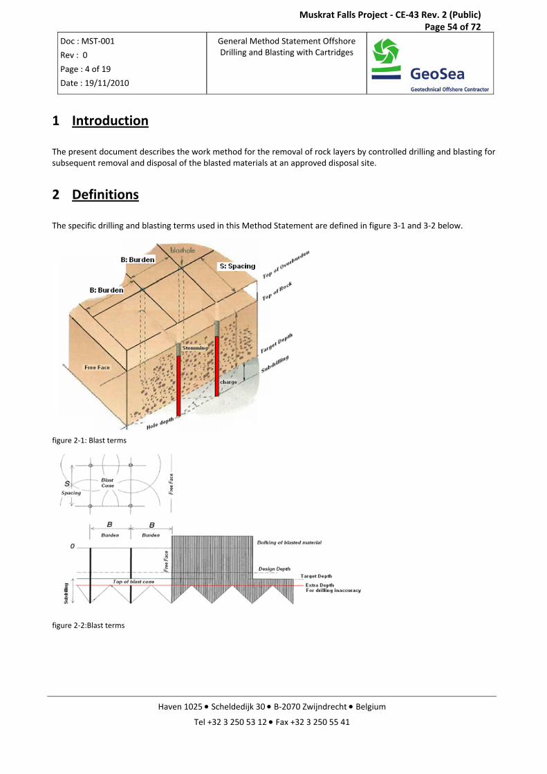
2 Definitions
The specific drilling and blasting terms used in this Method Statement are defined in figure 3‐1 and 3‐2 below.
figure 2‐1: Blast terms
figure 2‐2:Blast terms
Muskrat Falls Project - CE-43 Rev. 2 (Public) Page 54 of 72
Doc : MST‐001
Rev : 0
Page : 5 of 19
Date : 19/11/2010
General Method Statement Offshore Drilling and Blasting with Cartridges
Haven 1025 • Scheldedijk 30 • B‐2070 Zwijndrecht • Belgium
Tel +32 3 250 53 12 • Fax +32 3 250 55 41
3 Equipment
For smaller blasting areas and/or in case of shallow water depths following options can be chosen
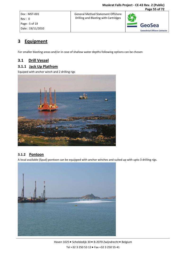
3.1 Drill Vessel 3.1.1 Jack Up Platfrom Equiped with anchor winch and 2 drilling rigs
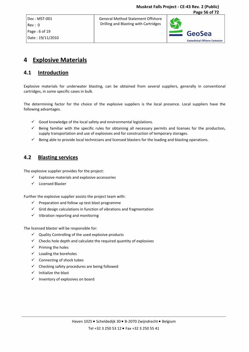
3.1.2 Pontoon A local available (Spud) pontoon can be equipped with anchor winches and suited up with upto 3 drilling rigs.
Muskrat Falls Project - CE-43 Rev. 2 (Public) Page 55 of 72
Doc : MST‐001
Rev : 0
Page : 6 of 19
Date : 19/11/2010
General Method Statement Offshore Drilling and Blasting with Cartridges
Haven 1025 • Scheldedijk 30 • B‐2070 Zwijndrecht • Belgium
Tel +32 3 250 53 12 • Fax +32 3 250 55 41
4 Explosive Materials
4.1 Introduction
Explosive materials for underwater blasting, can be obtained from several suppliers, generally in conventional cartridges, in some specific cases in bulk.
The determining factor for the choice of the explosive suppliers is the local presence. Local suppliers have the following advantages.
Good knowledge of the local safety and environmental legislations.
Being familiar with the specific rules for obtaining all necessary permits and licenses for the production, supply transportation and use of explosives and for construction of temporary storages.
Being able to provide local technicians and licensed blasters for the loading and blasting operations.
4.2 Blasting services
The explosive supplier provides for the project:
Explosive materials and explosive accessories
Licensed Blaster
Further the explosive supplier assists the project team with:
Preparation and follow up test blast programme
Grid design calculations in function of vibrations and fragmentation
Vibration reporting and monitoring
The licensed blaster will be responsible for:
Quality Controlling of the used explosive products
Checks hole depth and calculate the required quantity of explosives
Priming the holes
Loading the boreholes
Connecting of shock tubes
Checking safety procedures are being followed
Initialize the blast
Inventory of explosives on board
Muskrat Falls Project - CE-43 Rev. 2 (Public) Page 56 of 72
Doc : MST‐001
Rev : 0
Page : 7 of 19
Date : 19/11/2010
General Method Statement Offshore Drilling and Blasting with Cartridges
Haven 1025 • Scheldedijk 30 • B‐2070 Zwijndrecht • Belgium
Tel +32 3 250 53 12 • Fax +32 3 250 55 41
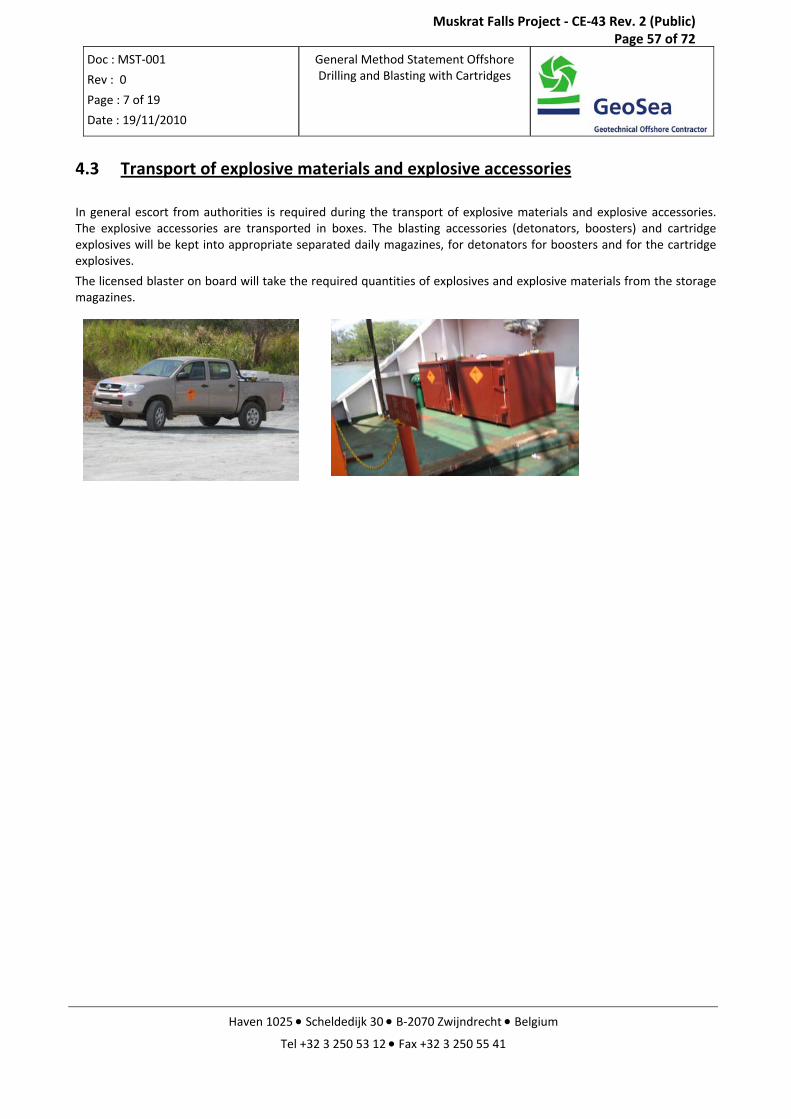
4.3 Transport of explosive materials and explosive accessories
In general escort from authorities is required during the transport of explosive materials and explosive accessories. The explosive accessories are transported in boxes. The blasting accessories (detonators, boosters) and cartridge explosives will be kept into appropriate separated daily magazines, for detonators for boosters and for the cartridge explosives.
The licensed blaster on board will take the required quantities of explosives and explosive materials from the storage magazines.
Muskrat Falls Project - CE-43 Rev. 2 (Public) Page 57 of 72
Doc : MST‐001
Rev : 0
Page : 8 of 19
Date : 19/11/2010
General Method Statement Offshore Drilling and Blasting with Cartridges
Haven 1025 • Scheldedijk 30 • B‐2070 Zwijndrecht • Belgium
Tel +32 3 250 53 12 • Fax +32 3 250 55 41
5 Work Method
The work method described below describes the work method for positioning and the sequence in loading and charging of the holes.
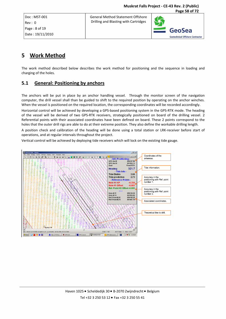
5.1 General: Positioning by anchors
The anchors will be put in place by an anchor handling vessel. Through the monitor screen of the navigation computer, the drill vessel shall than be guided to shift to the required position by operating on the anchor winches. When the vessel is positioned on the required location, the corresponding coordinates will be recorded accordingly.
Horizontal control will be achieved by developing a GPS‐based positioning system in the GPS‐RTK mode. The heading of the vessel will be derived of two GPS‐RTK receivers, strategically positioned on board of the drilling vessel. 2 Referential points with their associated coordinates have been defined on board. These 2 points correspond to the holes that the outer drill rigs are able to do at their extreme position. They also define the workable drilling length.
A position check and calibration of the heading will be done using a total station or LRK‐receiver before start of operations, and at regular intervals throughout the project.
Vertical control will be achieved by deploying tide receivers which will lock on the existing tide gauge.
Muskrat Falls Project - CE-43 Rev. 2 (Public) Page 58 of 72
Doc : MST‐001
Rev : 0
Page : 9 of 19
Date : 19/11/2010
General Method Statement Offshore Drilling and Blasting with Cartridges
Haven 1025 • Scheldedijk 30 • B‐2070 Zwijndrecht • Belgium
Tel +32 3 250 53 12 • Fax +32 3 250 55 41
5.2 Construction Plan
The blasting area will be subdivided in blasting zones linked to the anchor positions of the Drill Vessel
Each anchor position will be defined by: - The anchor possibility of the drill vessel depending on the position of the vessel towards the existing prism
lines (if any) on the project and the already blasted zones. - The safety zone where the drill vessel has to move during blasting.
Once a hole diameter chosen, the drill grid is dimensioned in function of the layer thickness and the expected fragmentation. The exact dimensions of the grid will be established after a test blast campaign and vibration monitoring of the surrounding structures.
The spacing and consequently the burden between blast holes will be optimized in such a way that the workable length on the drill vessel is maximally covered and that each drilling rig has to drill an equal number of holes.
Each blast zone, row and bore hole will receive a unique number to be used in all preparatory plans and reporting.
The sequence of the blasting zones will be defined by: - The safety zone to which the drill vessel has to move during blasting - Traffic - The interface between drilling and dredging activities to ensure the continuous operation of both dredging
and drilling vessel and the minimum safety distance between the Backhoe Dredge and the blast zone.
Possible hole diameters are 140mm for cartridges of 115mm. (Other drill bit diameters: for drill bit‐diameter of 125mm for cartridges with diameter 100mm and drill bit‐diameter 110 mm for cartridges of 85 mm)
Muskrat Falls Project - CE-43 Rev. 2 (Public) Page 59 of 72
Doc : MST‐001
Rev : 0
Page : 10 of 19
Date : 19/11/2010
General Method Statement Offshore Drilling and Blasting with Cartridges
Haven 1025 • Scheldedijk 30 • B‐2070 Zwijndrecht • Belgium
Tel +32 3 250 53 12 • Fax +32 3 250 55 41
Typical sequence of drilling and blasting with cartridge explosives
5.2.1 Positioning drill barge and position control Based upon the bathymetric survey a pre‐defined grid in DAL (Distance Along Line) and DOL (Distance Offset Line) with reference to the center line of the canal will be laid over the Rock area, economically covering the area for drilling and blasting purposes. Drilling and vessel positions will be expressed in DAL’s and DOL’s, hence easy to refer to and easier controllable.
5.2.2 Positioning drill rig After positioning the vessel to the intended drill row position, markers on the vessel indicating the spacing between blast holes are used to position the drill rig to the desired position.
Marks along the rail of the drill rig.
Muskrat Falls Project - CE-43 Rev. 2 (Public) Page 60 of 72
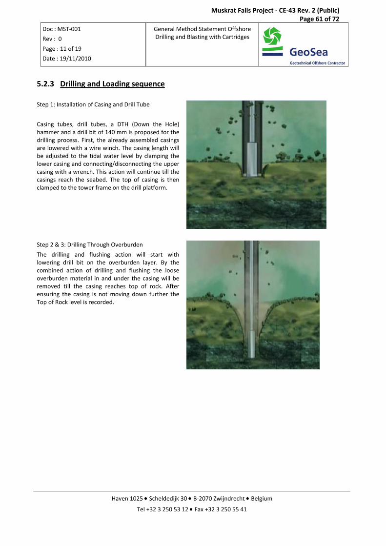
Doc : MST‐001
Rev : 0
Page : 11 of 19
Date : 19/11/2010
General Method Statement Offshore Drilling and Blasting with Cartridges
Haven 1025 • Scheldedijk 30 • B‐2070 Zwijndrecht • Belgium
Tel +32 3 250 53 12 • Fax +32 3 250 55 41
5.2.3 Drilling and Loading sequence Step 1: Installation of Casing and Drill Tube
Casing tubes, drill tubes, a DTH (Down the Hole) hammer and a drill bit of 140 mm is proposed for the drilling process. First, the already assembled casings are lowered with a wire winch. The casing length will be adjusted to the tidal water level by clamping the lower casing and connecting/disconnecting the upper casing with a wrench. This action will continue till the casings reach the seabed. The top of casing is then clamped to the tower frame on the drill platform.
Step 2 & 3: Drilling Through Overburden
The drilling and flushing action will start with lowering drill bit on the overburden layer. By the combined action of drilling and flushing the loose overburden material in and under the casing will be removed till the casing reaches top of rock. After ensuring the casing is not moving down further the Top of Rock level is recorded.
Muskrat Falls Project - CE-43 Rev. 2 (Public) Page 61 of 72
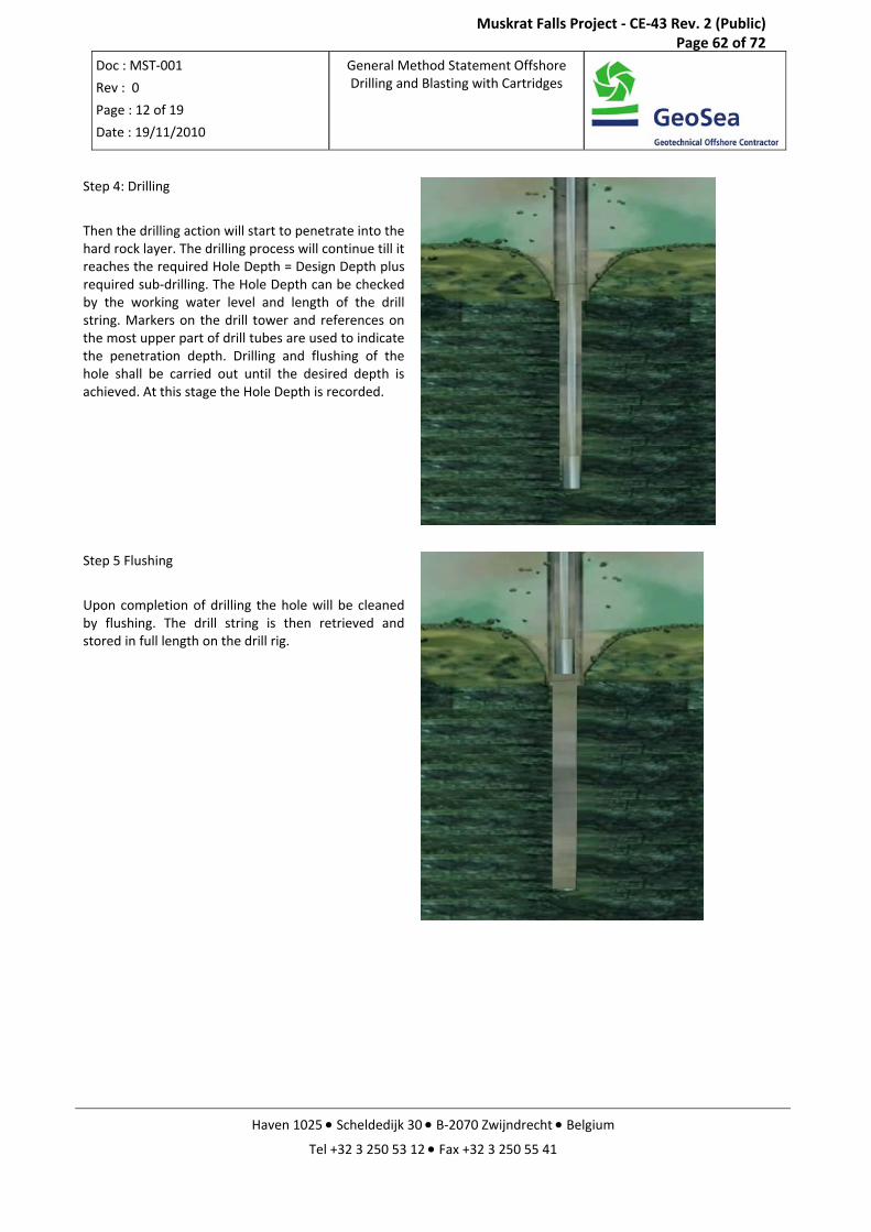
Doc : MST‐001
Rev : 0
Page : 12 of 19
Date : 19/11/2010
General Method Statement Offshore Drilling and Blasting with Cartridges
Haven 1025 • Scheldedijk 30 • B‐2070 Zwijndrecht • Belgium
Tel +32 3 250 53 12 • Fax +32 3 250 55 41
Step 4: Drilling
Then the drilling action will start to penetrate into the hard rock layer. The drilling process will continue till it reaches the required Hole Depth = Design Depth plus required sub‐drilling. The Hole Depth can be checked by the working water level and length of the drill string. Markers on the drill tower and references on the most upper part of drill tubes are used to indicate the penetration depth. Drilling and flushing of the hole shall be carried out until the desired depth is achieved. At this stage the Hole Depth is recorded.
Step 5 Flushing
Upon completion of drilling the hole will be cleaned by flushing. The drill string is then retrieved and stored in full length on the drill rig.
Muskrat Falls Project - CE-43 Rev. 2 (Public) Page 62 of 72
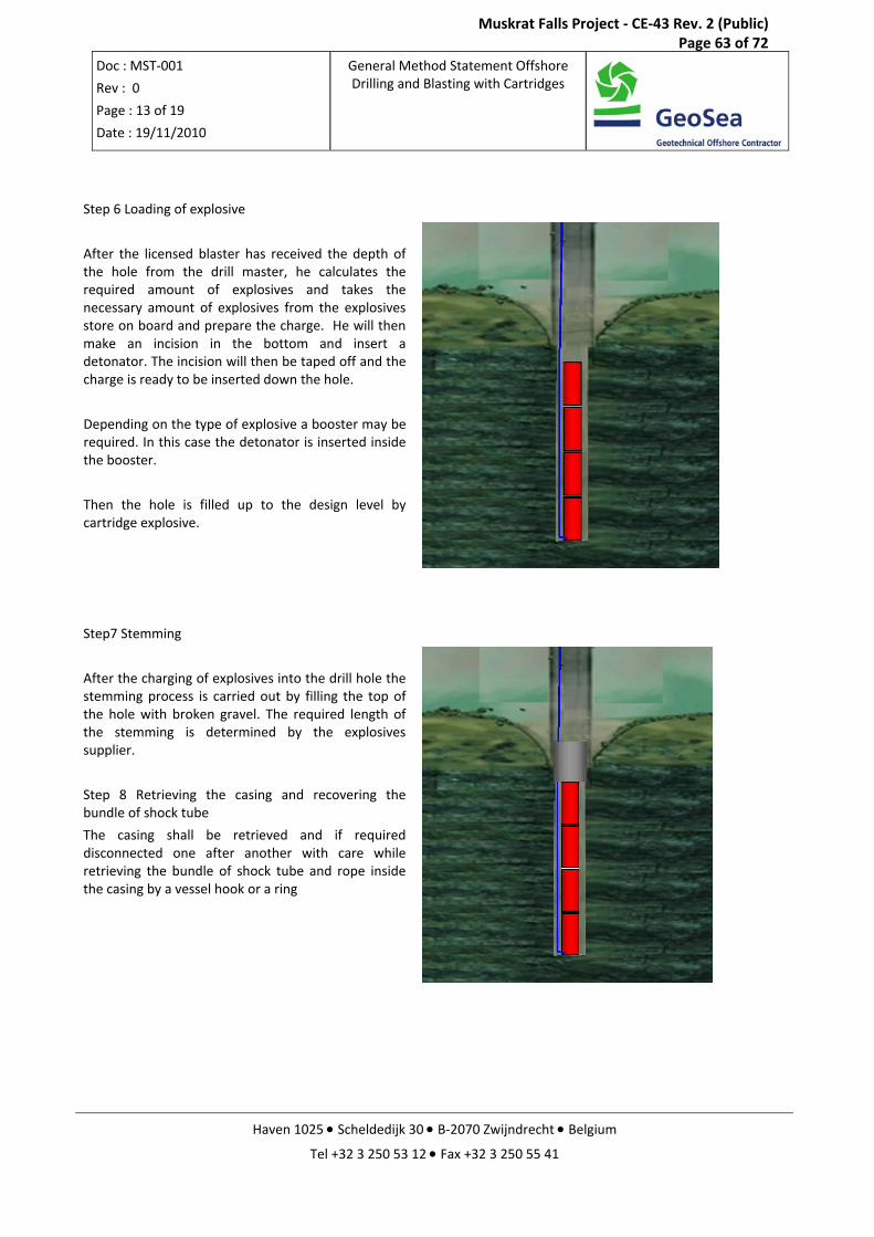
Doc : MST‐001
Rev : 0
Page : 13 of 19
Date : 19/11/2010
General Method Statement Offshore Drilling and Blasting with Cartridges
Haven 1025 • Scheldedijk 30 • B‐2070 Zwijndrecht • Belgium
Tel +32 3 250 53 12 • Fax +32 3 250 55 41
Step 6 Loading of explosive
After the licensed blaster has received the depth of the hole from the drill master, he calculates the required amount of explosives and takes the necessary amount of explosives from the explosives store on board and prepare the charge. He will then make an incision in the bottom and insert a detonator. The incision will then be taped off and the charge is ready to be inserted down the hole.
Depending on the type of explosive a booster may be required. In this case the detonator is inserted inside the booster.
Then the hole is filled up to the design level by cartridge explosive.
Step7 Stemming
After the charging of explosives into the drill hole the stemming process is carried out by filling the top of the hole with broken gravel. The required length of the stemming is determined by the explosives supplier.
Step 8 Retrieving the casing and recovering the bundle of shock tube
The casing shall be retrieved and if required disconnected one after another with care while retrieving the bundle of shock tube and rope inside the casing by a vessel hook or a ring
Muskrat Falls Project - CE-43 Rev. 2 (Public) Page 63 of 72
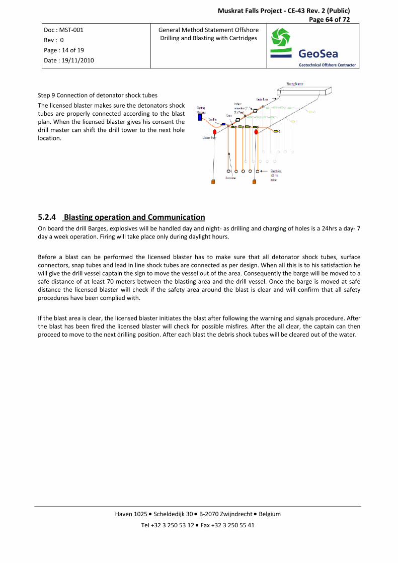
Doc : MST‐001
Rev : 0
Page : 14 of 19
Date : 19/11/2010
General Method Statement Offshore Drilling and Blasting with Cartridges
Haven 1025 • Scheldedijk 30 • B‐2070 Zwijndrecht • Belgium
Tel +32 3 250 53 12 • Fax +32 3 250 55 41
Step 9 Connection of detonator shock tubes
The licensed blaster makes sure the detonators shock tubes are properly connected according to the blast plan. When the licensed blaster gives his consent the drill master can shift the drill tower to the next hole location.
5.2.4 Blasting operation and Communication On board the drill Barges, explosives will be handled day and night‐ as drilling and charging of holes is a 24hrs a day‐ 7 day a week operation. Firing will take place only during daylight hours.
Before a blast can be performed the licensed blaster has to make sure that all detonator shock tubes, surface connectors, snap tubes and lead in line shock tubes are connected as per design. When all this is to his satisfaction he will give the drill vessel captain the sign to move the vessel out of the area. Consequently the barge will be moved to a safe distance of at least 70 meters between the blasting area and the drill vessel. Once the barge is moved at safe distance the licensed blaster will check if the safety area around the blast is clear and will confirm that all safety procedures have been complied with.
If the blast area is clear, the licensed blaster initiates the blast after following the warning and signals procedure. After the blast has been fired the licensed blaster will check for possible misfires. After the all clear, the captain can then proceed to move to the next drilling position. After each blast the debris shock tubes will be cleared out of the water.
Muskrat Falls Project - CE-43 Rev. 2 (Public) Page 64 of 72
Doc : MST‐001
Rev : 0
Page : 15 of 19
Date : 19/11/2010
General Method Statement Offshore Drilling and Blasting with Cartridges
Haven 1025 • Scheldedijk 30 • B‐2070 Zwijndrecht • Belgium
Tel +32 3 250 53 12 • Fax +32 3 250 55 41
6 Measurements and reporting during drilling, blasting and during and after blasting
During drilling:
Top of Rock
hole depth
Drilling Parameters
During Loading:
The licensed blaster will keep a record of the quantities of explosive products and accessories used per blast hole and of daily movement of explosives products on the drill barges. Products taken, used and left over for the next day are noted in a book that can be audited by the Client, Police and Authorities.
During and after blasting:
Vibration monitoring: peak particle velocity will be monitored, registered and controlled
NOX gas detection
Lightning detection
Blast video: a video will be taken from each blast
Under water overpressure: Under water overpressure will be regularly monitored to observe the effect of stemming and blasting without stemming.
Fragmentation: Dredging of the fragmented material will be monitored closely at all times to ensure the results of the blasting are satisfactory and to adjust and optimize the blast design when required.
Muskrat Falls Project - CE-43 Rev. 2 (Public) Page 65 of 72
Doc : MST‐001
Rev : 0
Page : 16 of 19
Date : 19/11/2010
General Method Statement Offshore Drilling and Blasting with Cartridges
Haven 1025 • Scheldedijk 30 • B‐2070 Zwijndrecht • Belgium
Tel +32 3 250 53 12 • Fax +32 3 250 55 41
7 Quality assurance & quality control
Upon contract award and before commencement of the works, a site specific Project Drilling and Blasting Quality Control Plan is made. This quality plan is the basis for all planned operations, and is completed with general quality procedures and‐if applicable‐ with site‐specific procedures and instructions. The whole Quality System is subjected to the Client’s approval.
Reporting:
Regular reporting is an important interface between Contractor and Client. Therefore the way and extend of reporting is agreed upon with the Client before starting the work.
Standard reporting includes:
Test Blast Programme: Multiple blasts will made in the Initial Phase before production Start Up this to determine the exact blast parameters for the rest of the Project.
Blasting Plans, before each blast
Vibration Report, after each blast
Daily Report
Weekly Report
Muskrat Falls Project - CE-43 Rev. 2 (Public) Page 66 of 72
Doc : MST‐001
Rev : 0
Page : 17 of 19
Date : 19/11/2010
General Method Statement Offshore Drilling and Blasting with Cartridges
Haven 1025 • Scheldedijk 30 • B‐2070 Zwijndrecht • Belgium
Tel +32 3 250 53 12 • Fax +32 3 250 55 41
8 HSE Upon contract award and before commencement of the works, a site specific Drilling and Blasting Health and Safety Plan is made.
During the execution of the project, all required procedures concerning Health, Safety, Environment and Security (HSES) will be followed. A number of Health and Safety Procedures are applicable on all drilling and blasting activities. All personnel onboard of the vessels will have all necessary safety certificates and all required permits.
In addition each blast vessel will be quipped with a set of hydrophones to scare away marine live just before blasting operations this to minimize the environmental impact.
The whole Drilling and Blasting Health, Safety, Environment and Security (HSES) Plan is subjected to the Client’s approval.
Muskrat Falls Project - CE-43 Rev. 2 (Public) Page 67 of 72
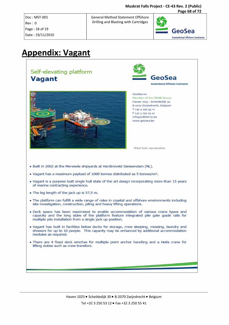
Doc : MST‐001
Rev : 0
Page : 18 of 19
Date : 19/11/2010
General Method Statement Offshore Drilling and Blasting with Cartridges
Haven 1025 • Scheldedijk 30 • B‐2070 Zwijndrecht • Belgium
Tel +32 3 250 53 12 • Fax +32 3 250 55 41
Appendix: Vagant
Muskrat Falls Project - CE-43 Rev. 2 (Public) Page 68 of 72
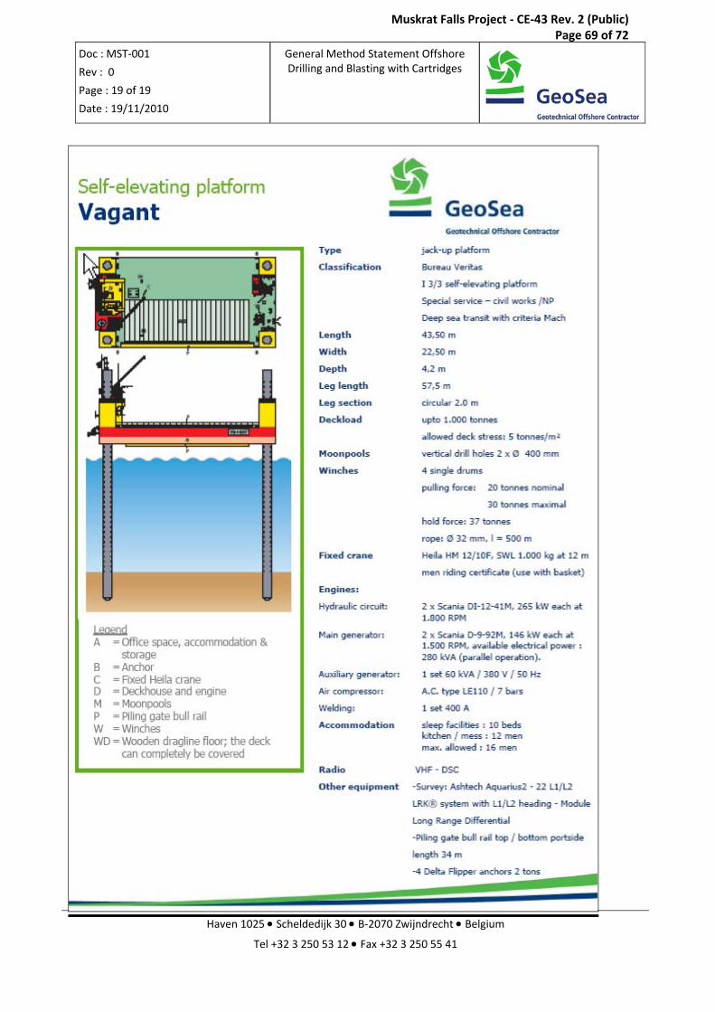
Doc : MST‐001
Rev : 0
Page : 19 of 19
Date : 19/11/2010
General Method Statement Offshore Drilling and Blasting with Cartridges
Haven 1025 • Scheldedijk 30 • B‐2070 Zwijndrecht • Belgium
Tel +32 3 250 53 12 • Fax +32 3 250 55 41
Muskrat Falls Project - CE-43 Rev. 2 (Public) Page 69 of 72
Nalcor Energy
Lower Churchill Project Pipeline Shore Approach and Landfall Study
Tideway Project T-CA-10.124
Revision 02 February 2011
APPENDIX C
LEAFLET BHD SAMSON
Muskrat Falls Project - CE-43 Rev. 2 (Public) Page 70 of 72
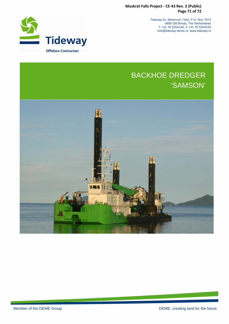
Tideway bv, Minervum 7442, P.O. Box 7074 4800 GB Breda, The Netherlands
T +31 76 5204140, F +31 76 [email protected], www.tideway.nl
Member of the DEME Group DEME: creating land for the future
BACKHOE DREDGER‘SAMSON’
Muskrat Falls Project - CE-43 Rev. 2 (Public) Page 71 of 72
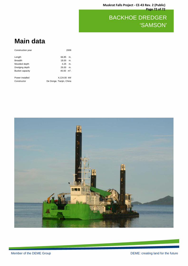
Tideway bv, Minervum 7442, P.O. Box 7074 4800 GB Breda, The Netherlands
T +31 76 5204140, F +31 76 [email protected], www.tideway.nl
D.P. FALL PIPE VESSEL‘ROLLINGSTONE’
Tideway B.V. Marine and Offshore Contractors, Topaasstraat 64, P.O. Box 7074, 4800 GB Breda, the Netherlands. Phone +31 76 520 4140.Fax: + 31 76 520 4150. [email protected] www.tideway.nl Member of the DEME Group of Companies (Dredging Environmental & Marine Engineering)
BACKHOE DREDGER ‘SAMSON’
Member of the DEME Group DEME: creating land for the future
Main dataConstruction year
LengthBreadthMoulded depthDredging depthBucket capacity
Power installedConstructor
2009
66.85 m.18.00 m.
4.25 m.26.00 m.40.00 m3.
4,124.00 kWDe Donge, Tianjin, China
Muskrat Falls Project - CE-43 Rev. 2 (Public) Page 72 of 72