Embed Size (px)
Citation preview

CE 479 J. Ramirez Built-up Roof Fall 2004 Page 1 Built-Up Roofs
Built-up Roof Definition: An assembly of interacting components designed, as part of the building
envelope, to protect the building interior, its contents, and its human occupants from the weather.
Design Factors: Roof must satisfy the local building code requirements and most probably an insurance
company’s requirement for wind and fire assistance. For each specific project, the best roof design results
from the combination of many factors. Ultimately the roof specification should consider at least the
following design factors:
1. First cost and life cycle (long term) cost
2. Value and vulnerability of building contents
3. Required roof life
4. Type of roof deck
5. Climate
6. Maintenance
7. Availability of materials and component applicators
8. Local practices.
Design of the built-up roof requires consultation with other members of the design team. The architect
must confer with the mechanical engineer about the heating and cooling loads to design the insulation and
to keep roof penetrations to a minimum. The architect must also consult with the structural engineer to
ensure appropriate framing stiffness and slope to avoid ponding due to excessive deflections. The
architect must also advise the owner to institute a periodic maintenance and inspection program. The
single most important problem facing the designer is the roof slope. Through long, sad experience, roof
designers have learned that ponded water is a major threat to the integrity of the roof system.
Roof Classification with Reference to Drainage:
a) Sloping: surfaced with overlapping shingles, tiles etc. Moderated to steep slope required for
water-tightness. Shingles, tiles are overlapped for water control.

CE 479 J. Ramirez Built-up Roof Fall 2004 Page 2 b) Flat or nearly flat: must be surfaced with a continuous waterproof membrane. - Built-up roof
systems.
We will concentrate on the nearly flat category as most major buildings (Purdue University for example)
use this type.
Components of Built-up Roof System (Nearly Flat)
A modern built-up roof system has the following basic components (see Fig. 1br):
a) structural deck,
b) vapor retarder, sometimes-used in roofs over humid interiors in northern climates (see Fig. 2br),
c) thermal insulation,
d) membrane: felts, bitumen, and mineral aggregate for surface protection,
e) flashing although not a basic component of the built-up roof system, is an important component. It
seals joints wherever the membrane is either pierced or terminated - at gravel stops, walls, curbs,
expansion joints, vents, and drains.
Figure 1br. Built-up system components
The built-up roof assembly including flashing, functions as a system in which each component depends on
the satisfactory performance of the others. For example the integrity of the vapor retarder, insulation, and
membrane depends on the satisfactory performance of the structural deck. Let’s discuss each component
individually in the order they appear from the inside of the building:

CE 479 J. Ramirez Built-up Roof Fall 2004 Page 3
Figure 2br. Built-up roof system components including vapor retarder
a) The Structural Deck: it transmits gravity, earthquake and wind forces to the roof framing (structural
system). Spans between roof beams or joists. Key design factors are:
1) Deflections
2) Anchorage of components
3) Strength and stability
4) Fire resistance
Types: - Reinforced concrete slabs, (CE 473)
- Timber or plywood (CE 479)
- Steel (ribbed metal deck, CE 479)
They can be classified as nailable or non-nailable for purposes of anchoring the vapor retarder, insulation,
or membrane to the deck. For example, timber should only be nailed. Reinforced concrete is limited to
non-nailed anchorages, except in rare instances when wood nailers are cast into its surface.
b) Vapor barrier (Retarder - optional): can be made of many various materials. A common vapor retarder,
often known as “vapor seal”, comprises three bituminous moppings with two plies of saturated felt or two
bituminous moppings enclosing an asphalt-coated base sheet. It forms an essentially impermeable

CE 479 J. Ramirez Built-up Roof Fall 2004 Page 4 surface on the warm, humid side of the roof sandwich, blocking the entry of water vapor. They are used
only in roofing systems where the insulation is sandwiched between the structural deck and the built-up
membrane. If properly designed can prevent condensation from forming within the built-up roofing
system.
Water vapor flowing upward into the insulation impairs the insulation’s thermal resistance, and may
ultimately destroy the insulation itself. However, if the insulation contains moisture when installed, the
vapor retarder does not allow it to escape because the retarder forms the bottom of a sandwich whose top
is the membrane. Moreover, it is difficult to ensure its integrity under the rigors of construction. Thus a
vapor retarder almost always admits some water vapor and the prudent designer will also design for its
escape by providing some form of venting –edge venting or stack venting in large area roofs. During the
winter in northern climates the water vapor flows upward through the roof, from a treated interior toward a
colder drier exterior (i.e. from high to low pressure, along the pressure gradient.) A recommended vapor
retarder assembly is the one shown in Fig. 2br.
To qualify as a vapor retarder, a materials vapor permeance rating should not exceed 0.1 perm. A
material rated as 1 perm, admits 1 grain of water vapor per hour through 1 ft2 of material under pressure
differential of .491 psi (1 in. of Mercury, Hg). Vapor resistance is the reciprocal of permeance. In severely
cold northern climates, where the vapor-pressure differential may persist in the same upward direction for
weeks, a virtually impermeable vapor barrier is needed to prevent a destructive moisture build-up within
the built-up roof system. Normally, it should not be needed unless the interior relative humidity exceeds
40% and January temperature average less than 35oF.
c) Thermal Insulation: Reduces heating and cooling costs and prevents condensation on interior building
surfaces. In cold weather, it raises interior surface temperatures, thus reducing radiative losses that chill

CE 479 J. Ramirez Built-up Roof Fall 2004 Page 5 occupants. In the summer, it reduces interior surface. With its horizontal shearing resistance, it helps
relieve stresses transferred to the membrane due to movement in the structural deck. It also provides an
acceptable flat surface for the application of the membrane, particularly on steel decks. Although it is
preferable to provide underneath the insulation a ½" board. It worst enemy is moisture or freeze-thaw
damage.
Desired Characteristics:
⋅ Good shearing strength, to distribute tensile stresses in the membrane and prevent splitting.
⋅ Compressive strength to withstand traffic loads and, especially in the midwestern states, hailstone
impact (30 psi minimum).
⋅ Adhesive and cohesive strength to withstand wind uplift.
⋅ Dimensional stability under thermal and moisture changes.
Because of these requirements, the design of thermal insulation and choice of materials is a complex task.
Drawbacks related to the use of insulation:
1. Increases the probability of condensation within the roof system in the winter months. The
introduction of insulation between the deck and the membrane usually shifts the dew point from
below the roof system to within the roof system. Thus migrating water vapor will condense
probably at the underside of the membrane and will be trapped in the insulation material. Thus
reducing its effectiveness.
2. It raises the surface, temperature in the summer (see Fig. 3br) by trapping heat at surface. This
figure shows that extreme roof temperatures produced by insulation sandwiched between deck
and roof membrane can make an insulated roof surface 40 °F hotter in sunlight and 10 °F colder
at night than an uninsulated roof membrane. The extreme high temperatures accelerate the
oxidizing chemical reactions that harden bitumen and make it more brittle and more subject to
cracking and degradation in general. The extreme temperature cycling further accelerates the

CE 479 J. Ramirez Built-up Roof Fall 2004 Page 6
membrane deterioration. The thermal contractions lead to splitting.
Figure 3br. Extreme roof temperatures produced by insulation
Types:
⋅ Rigid insulation: prefabricated into boards applied directly to the deck surface.
⋅ Dual-purpose structural deck and insulating planks: (Preformed, mineralized wood fiber, in 1½ to
3½ in. thick planks) - long wood fibers bonded with a cement binder (or resinous) and formed
under a combination of heat and pressure. Some of these planks have an integrally bonded
urethane foam surface, for a more efficient dual structural-insulating function (organic). Fiberboard
insulations are the more vulnerable to moisture, which eventually roots and weakens any fibrous
organic board.
⋅ Poured in place insulating concrete fills:
Lightweight concrete using perlite or vermiculite aggregates, which, contains varied-sized cells
that raise the concrete’s thermal resistance to 14-20 times that of ordinary structural concrete.

CE 479 J. Ramirez Built-up Roof Fall 2004 Page 7
- Perlite: silicaceous volcanic glass
- Vermiculite: expanded mica
They economically provide both insulation and a sloped roof surface for drainage. They also
provide a smooth base on top of steel decks, precast concrete and other decks for applications of
the membrane or additional insulation boards, if needed.
Another advantage over lighter materials, the more massive insulating materials such as lightweight
concrete (which could weigh 50 times as much as say foamed plastic of an equivalent thermal resistance)
stabilize the extreme fluctuations of an insulated roof’s surface temperatures. A roof membrane directly
on top of a light, highly efficient insulation reacts to the sudden heat of the sun like an empty pan on a
burner. The metal in contact with a good insulator - in this case air - heats up faster than the metal of a
pan filled with a poor insulator like water. A massive insulating material, like the water in the heated pan,
has a greater heat capacity than a lighter more efficient insulator. Because they store and release heat
slower than thinner, lighter insulation, these heavier materials tend to stabilize roof-surface temperatures.
Thus, the temperature in the membrane reacts less quickly to the sudden heat of the sun emerging from
behind the clouds, or to the chill of a sudden rain shower (sees Fig. 4br). The cooling-load temperature
curves (for an interior temperature of 78 °F and for a summer day with maximum 95 °F air temperature) in
Figure 4br show how increased roof-system mass reduces peak cooling load leading to a more uniform
cooling-load curve from solar heat gain. Heavy roof construction retards solar heat gain by absorbing the
heat and slowly releasing it. Lightweight roof construction in Fig. 4br is represented by steel deck + 1 to 2
in. of insulation + suspended ceiling, intermediate roof construction consists of wood decking = 1 to 2 in. of
insulation + suspended ceiling, and heavy roof construction consists of 6 inches of concrete deck + 1 to 2
in. of insulation + suspended ceiling.

CE 479 J. Ramirez Built-up Roof Fall 2004 Page 8
Figure 4br. Cooling-load curves from solar heat gain for three types of roofs
However, there are disadvantages with the use of this type of decking material. It poses an especially
severe moisture-absorption problem because it may retain high-moisture content for years. Unless it is
properly vented, lightweight concrete fill can maintain a considerable amount of entrapped water with the
following consequences:
⋅ shortened membrane life from increased probability of blistering (from vapor migrating upward into
voids in the membrane) and splitting (from water weakening the membrane felts).
⋅ Reduction in the roof system’s thermal resistance. With dry-basis moisture (Eq. 1) of 50%,
vermiculite aggregate concrete can suffer a reduction of up to 75% of its dry-state thermal
insulating value.
dry wt.-ovendry wt. oven- weightTotal = moisture % basis-Dry (1)

CE 479 J. Ramirez Built-up Roof Fall 2004 Page 9 The proper venting of this type of insulation material is critical. A poured-in-place structural concrete deck
is a poor substrate for lightweight insulating concrete, and it is generally unacceptable to roofing
manufacturers. Lightweight insulating concrete should be restricted to decks with underside
venting: slotted steel decks, permeable formboards (fiberglass), or precast sections with venting
joints. In general, although conventional wisdom of the roofing industry backs topside venting of
insulation, it actually may do more harm than good. Underside venting is preferable. It is obligatory for
lightweight concrete fills. As an alternative edge venting can be considered.
d) Built-up Membrane: (see Fig. 1br)
It is the weatherproofing component of the roof system:
Components:
⋅ Felts: stabilize and strengthen bitumen
⋅ Bitumen: water proofing agent
Fig. 1br
⋅ Surfacing: mineral aggregate
Felts and bitumen are alternated, and the surfacing consists of mineral aggregate. The bitumen, asphalt,
is the waterproofing agent. The felts stabilize and strengthen the bitumen (asphalt), control its flow when

CE 479 J. Ramirez Built-up Roof Fall 2004 Page 10 warm and tensile strength when cold and brittle. Mineral aggregate surfacing consists of gravel or crushed
rock and it protects the bitumen from solar radiation, wind, and rain and foot traffic abrasion. The
membrane forms a semi-flexible roof covering, with as few as two and as many as five plies of felt custom-
built to fit the contours of the deck. No membrane can resist large movements in the deck or insulation.
They have poor resistance against puncture. Where heavy traffic is expected, the designer should provide
walkways.
e) Flashings: (see Fig 1br) they can be classified in two general types:
Base Flashings: These form the upturned edges of the membrane where it is terminated.
Normally made of bitumen and impregnated felts or fabrics.
Counter flashing (cap-flashing): which shield the exposed joints of the base flashing. Often
made of sheet metal: aluminum or galvanized steel. Must be paid close attention, as they are
often source of roof leaks.

CE 479 J. Ramirez Built-up Roof Fall 2004 Page 11 Principles of Thermal Insulation:
Heat is transferred through:
(1) Conduction
(2) Convection
(3) Radiation
Conduction: It depends on direct contact to transmit heat (kinetic energy).
Convection: It requires an air or liquid current, or some moving medium to transfer heat from one place
to another.
Radiation: It transmits heat through electromagnetic waves emitted by all bodies (at an intensity
varying with the fourth power of the absolute temperature).
Sun rays (radiation) account for the extremes in roof temperatures (surface), they can increase the surface
temperature of an insulated roof 75oF above air temperature, and on a clear night without cloud cover to
reflect radiated heat back to earth, roof-surface temperature can be 10oF or more below the air
temperature. Thus, in a climate with design temperature varying from a summer maximum of 95oF to a
winter low of 0oF, the annual variation in roof temperature may be 160oF or more.
Because it conducts less heat to or from the roof surface, insulation within the roof sandwich
“increases” the extremes in roof-surface temperature.
Heat primarily flows through building materials by means of conduction and convection.
Through an air space all three modes of heat transfer are at work. Thermal insulation resists all
three, but primarily conduction.
Factors Affecting Thermal Insulation:
1. % of air entrapment (air is a poor heat conductor) so the more air entrapped in all the cell, the
lower the transfer of heat.

CE 479 J. Ramirez Built-up Roof Fall 2004 Page 12 2. Capacity for impeding air flow.
3. Material’s own thermal conductivity. A good thermal insulator is a poor thermal conductor.
4. Color: If it is sufficiently opaque, it resists the penetration of heat radiation.
5. Temperature: Rising temperature reduces insulation’s thermal resistance (i.e. it increases thermal
conductivity). Thermal conductivity increases with faster movement of gaseous molecules
transmitting heat energy from one surface to another. Temperature is an index of this internal
molecular movement.
6. Moisture: Water filling an insulating material void generally replaces air. Water’s thermal
conductivity is more than 20 times as much as air; at above-freezing temperatures, nearly 100
times as much at subfreezing temperatures. (Foamglass is the best: it has a water-resistant,
closed-cell structure that protects it against water penetration)

CE 479 J. Ramirez Built-up Roof Fall 2004 Page 13 Heat Flow Determination
Heat transfer calculations require the knowledge of four indicators of heat transmission:
1. Thermal conductivity k - heat [Btu] transferred per hour (Btu/hr) through a 1-in.-thick, 1-ft2 area
of homogeneous material per oF temperature difference from surface to surface. The unit for k is
Btu(in)/[(hr)( ft2 )( oF)]. To qualify as thermal insulation, a material must have a k ≤ 0.5.
2. Conductance C = k/thickness is the corresponding unit for a material of given thickness. (The
unit for C is Btu/[(hr)( ft2 )( oF)]. For a 2-in.-thick plank of material whose k = 0.20, C = 0.10.
3. Thermal resistance R = 1/C : indicates a material’s resistance to conductive heat flow, the unit
for R is Btu
fthrF 2o ••. A material with R = 5.0 (C = 0.2) means that for a 5oF temperature
difference surface-to-surface, 1 Btu/h flows through a 1-ft2 specimen, or it would take 5 hours to
transmit 1 Btu through 1 ft2 per oF.
4. Overall coefficient of transmission U: measured in Btu/[(h) ( ft2 of construction) (oF)] from air on
one side to air on the other. It is a function of the several component materials in a wall or roof:
where R = sum of the thermal resistances of the components, plus the resistances of the inside
and outside air films.
R1 U
Σ≅
To calculate the insulation’s required thermal resistance, Ri, the designer usually starts with a target U
factor set by the mechanical engineer. For the other components, the designer tabulates the resistances

CE 479 J. Ramirez Built-up Roof Fall 2004 Page 14 R for all the other materials, including, outside and inside air films.
C, conductance of various material are available from the ASHRAE (American Society of Heating,
Refrigerating, and Air-Conditioning Engineers) Handbook and Product Directory (see Figure 5br).

CE 479 J. Ramirez Built-up Roof Fall 2004 Page 15
Figure 5br. Thermal properties of construction materials [From: Mechanical and Electrical Equipment for Buildings, Stein and Reynolds, 1992.

CE 479 J. Ramirez Built-up Roof Fall 2004 Page 16
Figure 5br. Thermal properties of construction materials
[From: Mechanical and Electrical Equipment for Buildings, Stein and Reynolds, 1992
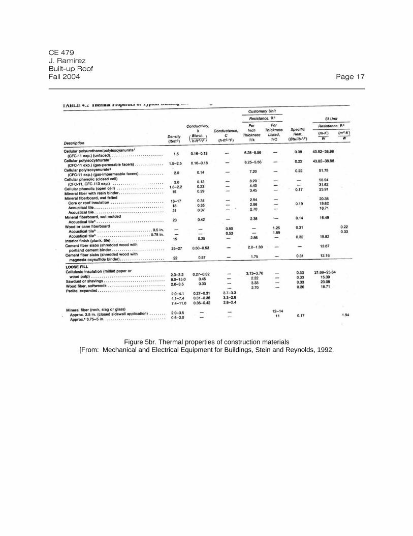
CE 479 J. Ramirez Built-up Roof Fall 2004 Page 17
Figure 5br. Thermal properties of construction materials
[From: Mechanical and Electrical Equipment for Buildings, Stein and Reynolds, 1992.

CE 479 J. Ramirez Built-up Roof Fall 2004 Page 18
Figure 5br. Thermal properties of construction materials
[From: Mechanical and Electrical Equipment for Buildings, Stein and Reynolds, 1992

CE 479 J. Ramirez Built-up Roof Fall 2004 Page 19
Figure 5br. Thermal properties of construction materials [From: Mechanical and Electrical Equipment for Buildings, Stein and Reynolds, 1992

CE 479 J. Ramirez Built-up Roof Fall 2004 Page 20
Figure 5br. Thermal properties of construction materials [From: Mechanical and Electrical Equipment for Buildings, Stein and Reynolds, 1992

CE 479 J. Ramirez Built-up Roof Fall 2004 Page 21
Figure 5br. Thermal properties of construction materials [From: Mechanical and Electrical Equipment for Buildings, Stein and Reynolds, 1992

CE 479 J. Ramirez Built-up Roof Fall 2004 Page 22 Roof Drainage
Why Drainage in Flat Roofs (BUR)?
Damage from ponding on BUR
1) Freezing of ponded water which has penetrated can delaminate or split the membrane.
2) Standing water can promote the growth of vegetation, fungi etc.
3) Temperature variations on a randomly ponded roof can warp and wrinkle the membrane.
4) Evidence of ponded water nullifies some manufacturers’ roofing bonds. (Manufacturer’s bond -
issued by manufacturer guarantees the owner that the manufacturer will finance membrane
repairs required to stop leaks arising from ordinary wear).
Drainage systems are divided into two categories:
- interior
- peripheral
In an interior drainage system, water flows from elevated peripheral areas to interior roof drains. Leaders
(usually located at columns) conduct water through the building interior (see Figure 6br).
In a peripheral system water flows in the opposite direction to leaders and scuppers located outside the
building. The main advantage of the interior system is that it is weather protected.
To ensure good drainage, specify a minimum of two drains for a total roof area of less than 10,000 ft2.
Add at least one additional drain for each additional 10,000 ft2 of roof area and limit the maximum spacing
in any direction to 75 ft.
Provide sumps at drains to prevent local ponding. Required drain pipe size depends on:
⋅ contributory area
⋅ rainfall rate (in./hr)
⋅ roof slope (in./ft)

CE 479 J. Ramirez Built-up Roof Fall 2004 Page 23 For example:
A 1in./hr rainfall rate builds up at a 0.0104 gpm/ft2 rate. (1 gal = 231 in3, gpm/ft2 = 144/(231 x 60) = 0.0104
gpm (ft.in.hr) rainfall). For Indiana (see Figure 6br), say Indianapolis, rainfall is 2.8 in./hr. Hence gpm
(2.8)(.0104) = 0.029. For a 10,000 ft2 contributing drain area, you need a drain capacity of
From Figure 6br a single interior vertical drain pipe diameter of 5" would provide 360 gpm, giving adequate
capacity. For the first 10,000 ft2, since a minimum of two drains is required (with a capacity of at least 146
gpm each), a 4” pipe diameter would be adequate.
gpm 291.2 = 10000 x 0.029

CE 479 J. Ramirez Built-up Roof Fall 2004 Page 24
Figure 6br. Drain pipe design