Embed Size (px)
Citation preview
1
Crest® + Oral-B® at dentalcare.com | The trusted resource for dental professionals
Cone-Beam Computed Tomography (CBCT) Applications in Dentistry
Continuing Education
Brought to you by
Course Author(s): Diane J. Flint, DDS, MS, Diplomate ABOMR, Diplomate ABGD; Regina Casian Ruiz Velasco, DDS, Post-doctoral resident in OMRCE Credits: 2 hoursIntended Audience: Dentists, Dental Hygienists, Dental Students, Dental Hygiene StudentsDate Course Online: 11/01/2017 Last Revision Date: N/A Course Expiration Date: 10/31/2020Cost: Free Method: Self-instructional AGD Subject Code(s): 149, 730Online Course: www.dentalcare.com/en-us/professional-education/ce-courses/ce531
Disclaimer: Participants must always be aware of the hazards of using limited knowledge in integrating new techniques or procedures into their practice. Only sound evidence-based dentistry should be used in patient therapy.
IntroductionThis course will review Cone-Beam Computed Tomography (CBCT) and its applications in clinical dentistry. The technology and how it differs from other types of dental imaging, keys for optimal imaging based on the desired outcomes, radiation dose to patients, interpretation, and medico-legal considerations will be discussed.
Conflict of Interest Disclosure Statement• The authors report no conflicts of interest associated with this course.
ADA CERPThe Procter & Gamble Company is an ADA CERP Recognized Provider.
ADA CERP is a service of the American Dental Association to assist dental professionals in identifying quality providers of continuing dental education. ADA CERP does not approve or endorse individual courses or instructors, nor does it imply acceptance of credit hours by boards of dentistry.
Concerns or complaints about a CE provider may be directed to the provider or to ADA CERP at: http://www.ada.org/cerp
Approved PACE Program ProviderThe Procter & Gamble Company is designated as an Approved PACE Program Provider by the Academy of General Dentistry. The formal continuing education programs of this program provider are accepted by AGD for Fellowship, Mastership, and Membership Maintenance Credit. Approval does not imply acceptance by a state or provincial board of dentistry or AGD endorsement. The current term of approval extends from 8/1/2013 to 7/31/2021. Provider ID# 211886
2
Crest® + Oral-B® at dentalcare.com | The trusted resource for dental professionals
Course Contents• Overview• Learning Objectives• Introduction• Principles of CBCT• Image Acquisition and Reconstruction
Voxel Spatial Resolution
• Image Interpretation• Image Artifacts• Applications of CBCT in Clinical Dentistry
Implant Dentistry Pre-surgical Evaluation Paranasal Sinuses Orthodontics Endodontics Airway Analyses Temporomandibular Joints (TMJs)
• Conclusion• Course Test• References• About the Authors
OverviewCone-Beam Computed Tomography (CBCT) is an imaging modality that has shown a tremendous upward trend since its introduction in the late 1990s. The technology, keys for optimal imaging based on desired outcomes and exposure factors, and information on image analysis will be discussed.
Learning ObjectivesUpon completion of this course, the dental professional should be able to:• Describe CBCT technology and how it differs
from other intraoral or extraoral dental imaging.
• Describe dental scenarios as to when a CBCT scan might be an imaging modality of choice.
• Discuss the options in CBCT scan acquisition to limit radiation exposure to the patient.
• List steps to systematically review and interpret a CBCT scan.
• Discuss the ethical and medico-legal considerations of CBCT.
IntroductionCone-beam computed tomography (CBCT), also referred to as cone-beam volumetric tomography (CBVT) or cone-beam volumetric
imaging (CBVI), was introduced in Europe in the late 1990s and approved by the FDA for use in the United States in 2001.1 Because of the increasing applications of CBCT in dental practice over the past two decades, clinicians should seek to understand the basic concepts of this technology in order to provide appropriate treatment options for their patients.2
The main advantage of CBCT technology is the ability to view and analyze in three dimensions (3D) the patient’s osseous oral and maxillofacial structures, overcoming the magnification and superimposition of structures found with 2D imaging modalities like panoramic imaging.3,4 It is important to realize that with current CBCT technology only the bone and calcified structures are visualized along with airway spaces; soft tissue structures (muscles, glands, vasculature, soft tissue tumors) cannot be completely identified or assessed in a CBCT image. CBCT imaging provides high quality, accurate 3D representation of the osseous elements of the maxillofacial region.
When the patient is exposed to ionizing radiation, the beam passes through different tissues of varying densities. Structures with the highest density will be metallic materials, followed by enamel and bone. High density objects attenuate the x-ray beam, resulting in a reduction in the number of x-ray photons which strike the detector or sensor. Air does not attenuate the x-ray beam. The difference in densities are registered by the x-ray detector, and the computer applies a formula/algorithm for each attenuation. The result is a numeric matrix of an assigned value to each location, displayed on the computer monitor as an image of varying shades of gray. High density structures display as white/light in the image, while low density structures that do not attenuate the x-ray beam, such as air, display as black/dark.4,5
How much ionizing radiation is the patient receiving during the CBCT acquisition? A CBCT study emits more ionizing radiation than an intraoral series or panoramic imaging but approximately 10 times less than a medical MDCT. The amount of ionizing radiation will be different according to each manufacturer or CBCT unit. Some CBCT machines emit
3
Crest® + Oral-B® at dentalcare.com | The trusted resource for dental professionals
continuous radiation exposure, which means that during the entire acquisition process the unit is continually emitting ionizing radiation. Other CBCT units utilize pulsated radiation or intermittent radiation with less total radiation emitted.6
Radiation dose produced by CBCT is dependent on various machine parameters, such as field of view (FOV), peak kilovoltage (kVp), milliamperage (mA), continuous or intermittent beam, number of basis images, scan time and the degree of rotation.5 These are factors that will influence the amount of radiation absorbed by the patient. Some of these factors are specific to each machine and some are clinician dependent, especially the field of view selected. A leaded apron should be utilized for patient protection as long as it is not positioned between the X-ray source and the area of interest and may be required depending upon state laws.
CBCT is a type of imaging that offers many advantages over conventional or multidetector computed tomography (MDCT) used in medicine.4,5 In CBCT imaging the x-ray beam is cone- or pyramidal-shaped, as compared to the narrow fan-shaped x-ray beam in MDCT imaging.1,4,7 The CBCT unit typically makes a single rotation of 180 or 360 degrees around the patient’s head to acquire the two dimensional (2D) images, called “basis images;”7 the MDCT x-ray source must make many rotations around the patient to acquire the volume of images.1,5,8 A CBCT study has higher
spatial resolution, shorter scan time, lower cost, and lower radiation dose when compared with MDCT study.
All imaging modalities should follow the ALARA rule — As Low As Reasonable Achievable.4,9 This principle is the basis for radiologic safety. Not all the patients require a CBCT scan or 3D imaging.10 Radiation exposure is only warranted if the proposed study will provide beneficial clinical information. A clear objective needs to be established prior to scanning a patient and should not be used on a routine basis or for screening purposes on all individuals.9-11
Principles of CBCTCBCT units can be categorized according to patient positioning, field of view, clinical functionality, and detector type. Clinicians should consider all these characteristics prior to purchasing a unit. The first CBCT unit was similar in design to MDCT, with the patient in a supine (reclined) position during the scan. Most CBCT units have the patient seated or standing; this type of unit requires less space in the dental office and may be more accessible for wheelchair users.1,2
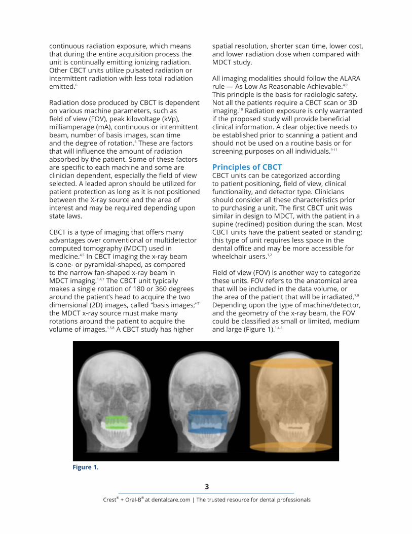
Field of view (FOV) is another way to categorize these units. FOV refers to the anatomical area that will be included in the data volume, or the area of the patient that will be irradiated.7,9 Depending upon the type of machine/detector, and the geometry of the x-ray beam, the FOV could be classified as small or limited, medium and large (Figure 1).1,4,5
Figure 1.
4
Crest® + Oral-B® at dentalcare.com | The trusted resource for dental professionals
request the smallest possible FOV to avoid unnecessary radiation exposure to the patient.9
There are also “hybrid systems” that have the capability of acquiring a panoramic projection image, posteroanterior or lateral cephalometric image, and limited FOV 3D images (CBCT).
Another way to categorize the CBCT units is according to the type of detector: CCD/image intensifier or flat panel detector.5 The size of the detector dictates the FOV capabilities of each unit. This is directly related to the price of the unit; the larger the detector the more expensive the unit will be. The CCD/II are bulkier and require greater floor space in the dental office, compared to the flat panel detector which is smaller and less room is needed.1
Image Acquisition and ReconstructionThere are two phases in CBCT imaging: the acquisition phase and the reconstruction phase. During the acquisition phase, the patient is positioned into the machine with the head stabilized to avoid movement during the acquisition of the data volume. After patient positioning, a scout view will be acquired to verify that the area of interest is within the FOV. This step is highly recommended for small FOV scans to verify that the desired area is included, to avoid additional scans and exposing the patient to extra radiation.
Once the clinician has assessed the scout image and approved it, the scan begins with rotation around the patient’s head, either 180 or 360 degrees, and the cone-shaped x-ray beam is directed through the center of the area of interest. The beam and the receptor rotate simultaneously around the patient’s head during the acquisition. During this rotation, basis images are acquired in intervals as the radiation passes through the patient and is captured by the receptor. A wide range of 150 to 600 2D images are collected in the detector within a few seconds.4,5 These 2D images are called basis images. The exact number of basis images will be determined by the degree of rotation and the time of acquisition. A faster scan will acquire fewer
The units that scan small or limited areas, cover approximately 5 teeth (5 cm diameter) and surrounding anatomical structures, resulting in less volume for which the practitioner is responsible to interpret. Small FOV scans are normally used for endodontic purposes due to the capability of high spatial resolution and ability to visualize changes to the periodontal ligament spaces (PDL) or lamina dura, root fractures, periapical lesions, relationship of an impacted tooth with the surrounding anatomical structures, and root canal morphology. One capability of the small field of view units is the ability to create a larger volume of the complete arch rather than just a few teeth through the stitching process.5 In this process, multiple adjacent limited field of view scans are united during the reconstruction phase to recreate one dental arch. The main disadvantage of the stitching technique is that the patient is exposed to multiple CBCT scans.1
Medium field of view is normally referred to those scans that image one arch or both dental arches, approximately 6-11 cm in height. When evaluation of the extent of a lesion or status of the temporomandibular joints is desired, a medium FOV is suggested. When both dental arches are scanned, a pseudopanoramic rendering can be derived from the data set. Medium field of view is also indicated in implant planning cases.
The large field of view is recommended for specific cases with skeletal anomaly/asymmetry and where orthodontic/orthognathic surgery is planned. The scanned area may range from 11 to 24 cm in height and covers most of the craniofacial skeleton. For comprehensive surgical planning, oral surgeons and orthodontists require a scan that extends from the inferior border of the mandible to the supraorbital ridges or vertex of the skull. The main disadvantage of the large FOV is the larger radiation exposure. With the large field of view the osseous structures of the temporomandibular joints and facial asymmetry can be evaluated. There are some manufacturers that offer the clinician the ability of acquiring different types of FOV according to their own needs. Each patient will present a unique situation, but it is important to always
5
Crest® + Oral-B® at dentalcare.com | The trusted resource for dental professionals
images, whereas a longer scan will acquire more basis images and thus more information will be provided and a better quality image will be created.
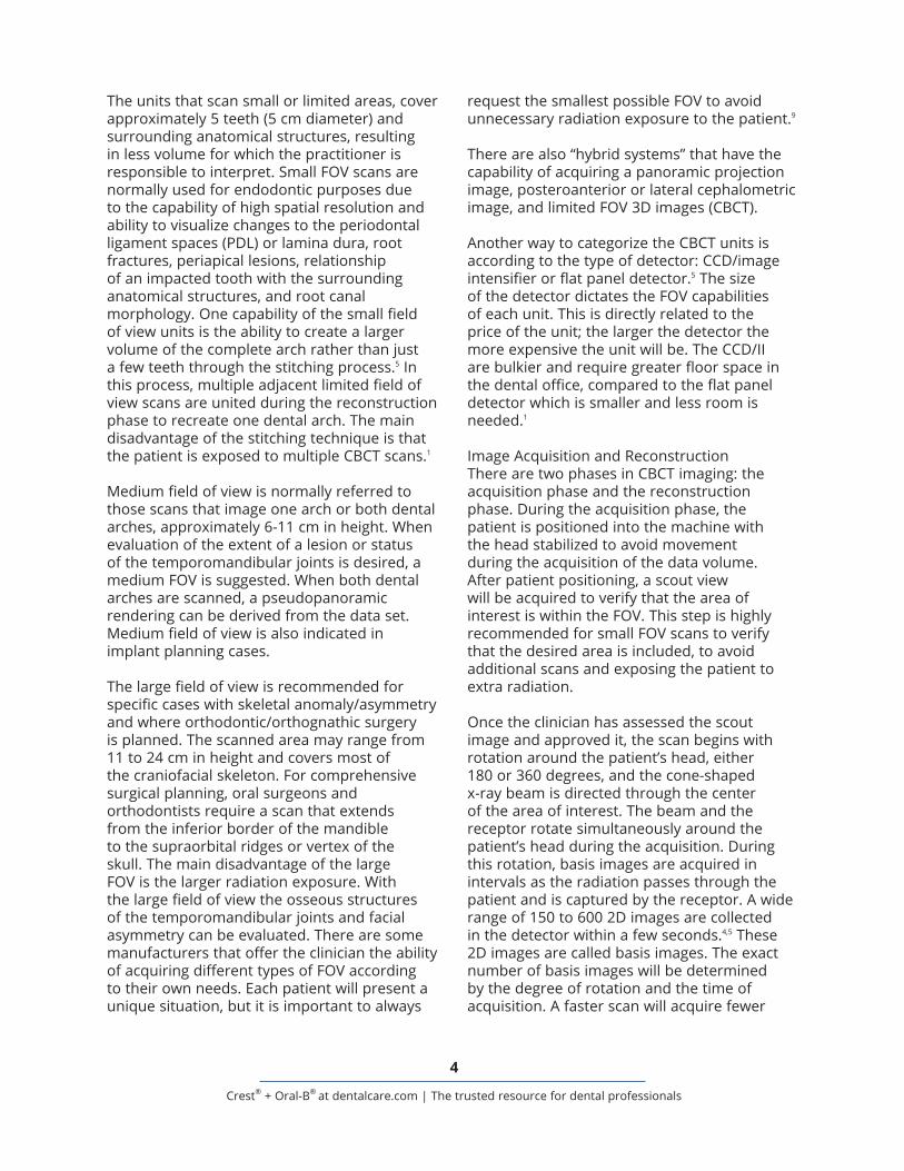
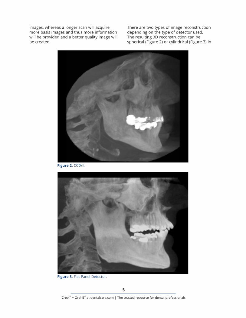
There are two types of image reconstruction depending on the type of detector used. The resulting 3D reconstruction can be spherical (Figure 2) or cylindrical (Figure 3) in
Figure 2. CCD/II.
Figure 3. Flat Panel Detector.
6
Crest® + Oral-B® at dentalcare.com | The trusted resource for dental professionals
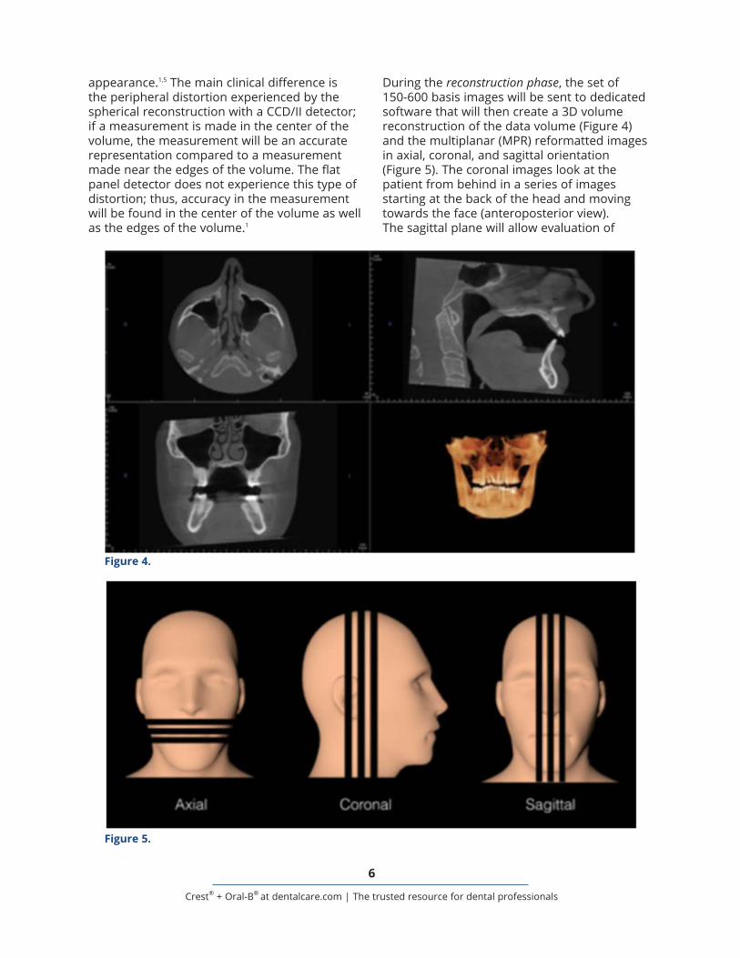
During the reconstruction phase, the set of 150-600 basis images will be sent to dedicated software that will then create a 3D volume reconstruction of the data volume (Figure 4) and the multiplanar (MPR) reformatted images in axial, coronal, and sagittal orientation (Figure 5). The coronal images look at the patient from behind in a series of images starting at the back of the head and moving towards the face (anteroposterior view). The sagittal plane will allow evaluation of
appearance.1,5 The main clinical difference is the peripheral distortion experienced by the spherical reconstruction with a CCD/II detector; if a measurement is made in the center of the volume, the measurement will be an accurate representation compared to a measurement made near the edges of the volume. The flat panel detector does not experience this type of distortion; thus, accuracy in the measurement will be found in the center of the volume as well as the edges of the volume.1
Figure 4.
Figure 5.
7
Crest® + Oral-B® at dentalcare.com | The trusted resource for dental professionals
cube or a box, with height, width and depth. Just as 2D images are made of several pixels (represented as squares, with height and width) and the smaller the pixel the better the quality of the picture, the same concept applies to a 3D data volume. Each three-dimensional voxel represents a specific x-ray absorption. The voxel size on CBCT images is isotropic, which means that all the sides are the same dimension with uniform resolution in all directions. In contrast, an MDCT voxel is in general nonisotropic meaning that one side of the voxel is different in dimension (Figure 7). This is considered an advantage of the CBCT because if a certain structure needs to be measured, the measurement will be exact in all the three orthogonal planes. There are different voxel sizes depending on the capabilities of each unit. The small field of view units may use a small voxel size of 0.076 mm, which enables visualization of very small changes to structures. Other voxel sizes available for CBCT units are 0.2 mm, 0.3 mm, 0.4 mm. It is important to note that the larger the voxel size, the less resolution the image will have and less capability to differentiate between small structures (Figure 8). The voxel size is dependent of the imaging objective and the size of the unit detector.
Voxel size needs to be smaller than the desired anatomical structure for adequate representation. For example, the first sign of periapical inflammatory lesion is discontinuity
the patient’s structures from side-to-side in a series of images starting at one ear and moving to the other. The axial plane evaluates the patient from below in a series of images starting at the chin and moving to the top of the head (axial view).2
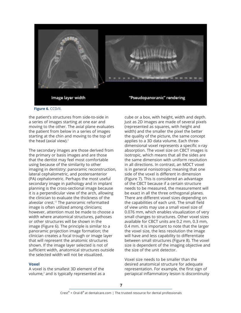
The secondary images are those derived from the primary or basis images and are those that the dentist may feel most comfortable using because of the similarity to other imaging in dentistry: panoramic reconstruction, lateral cephalometric, and posteroanterior (PA) cephalometric. Perhaps the most useful secondary image in pathology and in implant planning is the cross-sectional image because it is a perpendicular view of the arch, allowing the clinician to evaluate the thickness of the alveolar crest.12 The panoramic reformatted image is often utilized among clinicians; however, attention must be made to choose a width where anatomical structures, pathoses or other structures will be shown in the image (Figure 6). The principle is similar to a panoramic projection image formation; the clinician creates a focal trough or image layer that will represent the anatomic structures shown. If the image layer selected is not of sufficient width, anatomical structures outside the selected width will not be visualized.
VoxelA voxel is the smallest 3D element of the volume,2 and is typically represented as a
Figure 6. CCD/II.

8
Crest® + Oral-B® at dentalcare.com | The trusted resource for dental professionals
of the lamina dura; thus, if visualization changes to the periapical area (lamina dura and PDL space) is desired, a CBCT less than 0.2 mm needs to be acquired. Structures smaller than the voxel size will not be visualized in the scan (example, small cracks in the enamel). As previously mentioned, soft tissue structures
(mucosa, gingiva, cartilage, nerves, blood vessels) cannot be evaluated in a CBCT study.
Spatial ResolutionThere are different parameters that have direct influence on the resolution of an image. Voxel size is one of the most important parameters;
Figure 7.
Figure 8.
9
Crest® + Oral-B® at dentalcare.com | The trusted resource for dental professionals
however, field of view, scan time, number of basis images and type of detector also influence the resolution and quality of the scan. The longer the acquisition time, the more basis images are available. If a small voxel size is chosen the result will produce high spatial resolution but the amount of radiation exposure to the patient will be increased. These parameters change according to each patient situation. If a pediatric patient or an elderly patient has difficulty remaining still, a faster scan time might be the more appropriate way to evaluate a certain condition, resulting in decreased image resolution. As a general rule, the smaller the voxel size the higher the resolution.
Image InterpretationThere are two ways of reading the CBCT data set. The first is utilizing DICOM files (Digital Imaging and Communications in Medicine), which is both a communication protocol and a file format standard for handling, storing and transmitting information in medical imaging.4 The format ensures all the patient data and information stay together, as well as provides for transfer of the information between DICOM-supported devices from multiple manufacturers. The DICOM files are the 150-600 axial images that form the volume when they are merged together. Most implant companies offer their own DICOM file reading software, with different capabilities such as treatment planning or 3D printing of surgical guides. If the clinician does not have viewing software to allow uploading of the DICOM data, or the case does not require a 3D printed guide, the clinician can utilize a simple viewer to assess the images. The viewer will allow the clinician to evaluate the MPR images, make linear measurements and recreate a panoramic reformatted image. Other options typically found are zoom, magnification, brightness/contrast, rotation, and mandibular canal tracing.
The first step before analyzing the scan is to virtually reorient the patient data set until the arch is in a suitable position and the head is not tilted. The occlusal plane should be level with the horizontal plane. In the axial view, the midline should be coincidental
with the patient’s midline. This will help to evaluate symmetry of structures and avoid misinterpreting the images.
Once the patient reorientation is done, the MPR images can be read. It is very important to systematically read the entire comprehensive data volume. Key ideas to remember are to assess for symmetry and continuity of osseous borders. If the clinician does not feel comfortable assessing for abnormalities or pathologies in the skull base or cervical vertebrae, should they be within the field of view of the CBCT scan, consultation or scan interpretation by an oral and maxillofacial radiologist is paramount. The coronal MPR images are helpful to analyze anatomic structures with an anteroposterior orientation such as paranasal sinuses, nasal cavity, and some structures of the skull base (i.e., foramen rotundum). The axial images are helpful to analyze anatomical structures in a vertical path, with the sagittal images analyzing structures latero-medially.
The panoramic reformatted image is a useful tool because all teeth can be assessed in one image without superimposition and magnification that limits a 2D panoramic projection. The CBCT image is reconstructed based on a focal layer or trough, similar to a panoramic projection. The clinician can select the width and the extent of a focal trough in CBCT reformatting. However, an inappropriate choice of an image layer may lead to misdiagnosis. For example, an impacted maxillary canine may not be shown in the panoramic reformatted image if the selected curved image slice is not wide enough to include it. Some clinicians describe this reformat “pseudopanoramic.”
The most important feature of the panoramic rendering is that according to the path of its curved image slice, the cross-sectional image will be displayed. The cross-sectional image is a perpendicular image through the mandibular or maxillary arch. This image will assist in evaluating the height and width of the alveolar ridge for potential implant sites measurements, or the buccolingual extension of a pathosis and its relationship with the cortical bone.12
10
Crest® + Oral-B® at dentalcare.com | The trusted resource for dental professionals
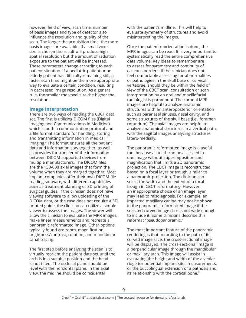
images are acquired due to a fast scan technique; it appears as small lines throughout the scan.
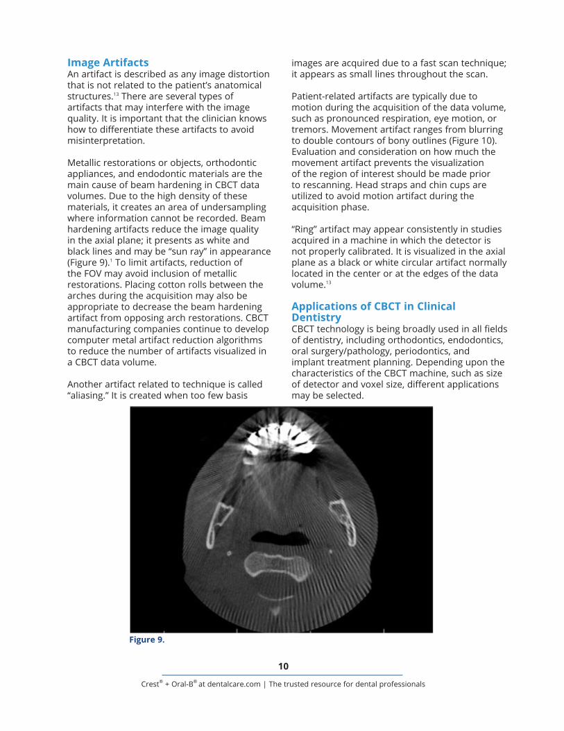
Patient-related artifacts are typically due to motion during the acquisition of the data volume, such as pronounced respiration, eye motion, or tremors. Movement artifact ranges from blurring to double contours of bony outlines (Figure 10). Evaluation and consideration on how much the movement artifact prevents the visualization of the region of interest should be made prior to rescanning. Head straps and chin cups are utilized to avoid motion artifact during the acquisition phase.
“Ring” artifact may appear consistently in studies acquired in a machine in which the detector is not properly calibrated. It is visualized in the axial plane as a black or white circular artifact normally located in the center or at the edges of the data volume.13
Applications of CBCT in Clinical DentistryCBCT technology is being broadly used in all fields of dentistry, including orthodontics, endodontics, oral surgery/pathology, periodontics, and implant treatment planning. Depending upon the characteristics of the CBCT machine, such as size of detector and voxel size, different applications may be selected.
Image ArtifactsAn artifact is described as any image distortion that is not related to the patient’s anatomical structures.13 There are several types of artifacts that may interfere with the image quality. It is important that the clinician knows how to differentiate these artifacts to avoid misinterpretation.
Metallic restorations or objects, orthodontic appliances, and endodontic materials are the main cause of beam hardening in CBCT data volumes. Due to the high density of these materials, it creates an area of undersampling where information cannot be recorded. Beam hardening artifacts reduce the image quality in the axial plane; it presents as white and black lines and may be “sun ray” in appearance (Figure 9).1 To limit artifacts, reduction of the FOV may avoid inclusion of metallic restorations. Placing cotton rolls between the arches during the acquisition may also be appropriate to decrease the beam hardening artifact from opposing arch restorations. CBCT manufacturing companies continue to develop computer metal artifact reduction algorithms to reduce the number of artifacts visualized in a CBCT data volume.
Another artifact related to technique is called “aliasing.” It is created when too few basis
Figure 9.
11
Crest® + Oral-B® at dentalcare.com | The trusted resource for dental professionals
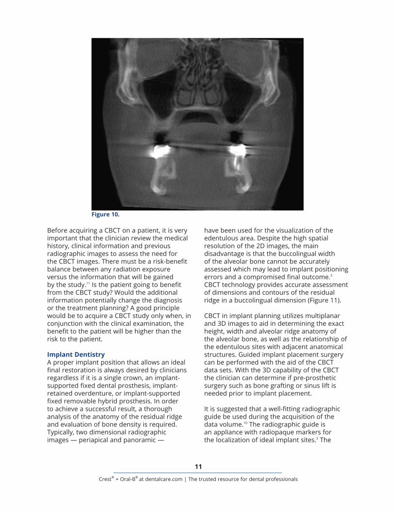
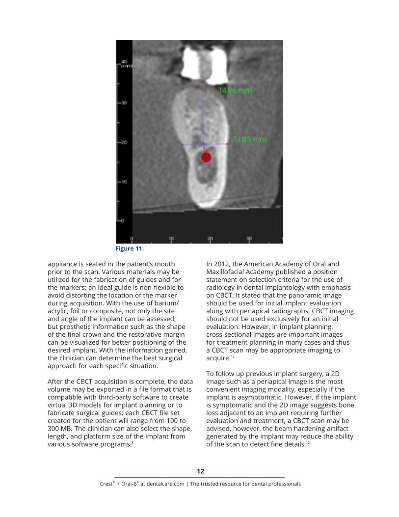
have been used for the visualization of the edentulous area. Despite the high spatial resolution of the 2D images, the main disadvantage is that the buccolingual width of the alveolar bone cannot be accurately assessed which may lead to implant positioning errors and a compromised final outcome.3 CBCT technology provides accurate assessment of dimensions and contours of the residual ridge in a buccolingual dimension (Figure 11).
CBCT in implant planning utilizes multiplanar and 3D images to aid in determining the exact height, width and alveolar ridge anatomy of the alveolar bone, as well as the relationship of the edentulous sites with adjacent anatomical structures. Guided implant placement surgery can be performed with the aid of the CBCT data sets. With the 3D capability of the CBCT the clinician can determine if pre-prosthetic surgery such as bone grafting or sinus lift is needed prior to implant placement.
It is suggested that a well-fitting radiographic guide be used during the acquisition of the data volume.10 The radiographic guide is an appliance with radiopaque markers for the localization of ideal implant sites.3 The
Before acquiring a CBCT on a patient, it is very important that the clinician review the medical history, clinical information and previous radiographic images to assess the need for the CBCT images. There must be a risk-benefit balance between any radiation exposure versus the information that will be gained by the study.11 Is the patient going to benefit from the CBCT study? Would the additional information potentially change the diagnosis or the treatment planning? A good principle would be to acquire a CBCT study only when, in conjunction with the clinical examination, the benefit to the patient will be higher than the risk to the patient.
Implant DentistryA proper implant position that allows an ideal final restoration is always desired by clinicians regardless if it is a single crown, an implant-supported fixed dental prosthesis, implant-retained overdenture, or implant-supported fixed removable hybrid prosthesis. In order to achieve a successful result, a thorough analysis of the anatomy of the residual ridge and evaluation of bone density is required. Typically, two dimensional radiographic images — periapical and panoramic —
Figure 10.
12
Crest® + Oral-B® at dentalcare.com | The trusted resource for dental professionals
In 2012, the American Academy of Oral and Maxillofacial Academy published a position statement on selection criteria for the use of radiology in dental implantology with emphasis on CBCT. It stated that the panoramic image should be used for initial implant evaluation along with periapical radiographs; CBCT imaging should not be used exclusively for an initial evaluation. However, in implant planning, cross-sectional images are important images for treatment planning in many cases and thus a CBCT scan may be appropriate imaging to acquire.12
To follow up previous implant surgery, a 2D image such as a periapical image is the most convenient imaging modality, especially if the implant is asymptomatic. However, if the implant is symptomatic and the 2D image suggests bone loss adjacent to an implant requiring further evaluation and treatment, a CBCT scan may be advised, however, the beam hardening artifact generated by the implant may reduce the ability of the scan to detect fine details.12
appliance is seated in the patient’s mouth prior to the scan. Various materials may be utilized for the fabrication of guides and for the markers; an ideal guide is non-flexible to avoid distorting the location of the marker during acquisition. With the use of barium/acrylic, foil or composite, not only the site and angle of the implant can be assessed, but prosthetic information such as the shape of the final crown and the restorative margin can be visualized for better positioning of the desired implant. With the information gained, the clinician can determine the best surgical approach for each specific situation.
After the CBCT acquisition is complete, the data volume may be exported in a file format that is compatible with third-party software to create virtual 3D models for implant planning or to fabricate surgical guides; each CBCT file set created for the patient will range from 100 to 300 MB. The clinician can also select the shape, length, and platform size of the implant from various software programs.3
Figure 11.
13
Crest® + Oral-B® at dentalcare.com | The trusted resource for dental professionals
Pre-surgical EvaluationClinicians shall identify potential harm to anatomical structures and should be able to determine the need for a pre-prosthetic surgery.
Visualization and mapping of the mandibular canal is one of the advantages of a CBCT study of the mandibular arch. For most patients, a well-defined, corticated radiolucent track will be visualized in cross-sectional images. It typically will be located adjacent to the lingual cortex, originating at the mandibular foramen and extending anteriorly to the mental foramen. The distance from the alveolar crest to the visualized superior border of the mandibular canal can be determined with accuracy with a diagnostic CBCT image. Changes in the path of the mandibular canal and variants of normal may be assessed as well.
In the anterior mandible, it is essential to evaluate the area and identify the anatomical structures of the mandibular incisive canal, the lingual canal and mental foramen to avoid hemorrhage and neurovascular damage.
In the posterior mandible the submandibular fossa extension is an area to be assessed prior to implant placement. The submandibular fossa is located below the mylohyoid muscle in the area of the mandibular molars. If a pronounced concavity is present, it may not be realized clinically or in a panoramic radiograph, with the potential for implant placement through the lingual cortical plate and high risk of hemorrhage that might be life threatening.
In the anterior maxilla, the incisive foramen is located posterior to central incisors and its diameter may vary. Size, exact localization and topography of such foramen is important because harm to this anatomical structure can cause neurovascular damage.
In the posterior maxilla, one of the important structures are the maxillary sinuses. When planning for a sinus lift, a CBCT of the area may be requested for evaluation of both sinus health and anatomy. The middle superior alveolar canal will be visualized as a small round radiolucent structure running antero-
posteriorly within the lateral wall of the maxillary sinus at the premolar area and should be identified prior to flap procedures in that area. Another anatomical structure in the posterior maxilla is the greater palatine foramen, located distal to the second molar area; its localization is extremely important for flap design. It is important to mention that in CBCT imaging, the location of the greater palatine foramen (osseous opening) will be visualized but the neurovascular bundle (soft tissue) will not be seen. After a sinus lift surgery, a CBCT study can give information regarding the post-surgical outline of bone grafting as well as how well-adapted the bone graft is.
When a block bone graft is planned, information gained from a CBCT scan will assist in donor site evaluation. Autologous bone graft is harvested from the patient’s symphysis or mandibular ramus. In the ascending ramus the distance from the mandibular canal to the buccal cortex should be accurately measured to avoid bleeding or neurological problems. Evaluation for the presence of bifid canals, not uncommon in the ascending ramus, should be determined. If the graft will be harvested from the symphysis, it is important to evaluate the anatomy of the area to avoid damaging apices of teeth or neurovascular bundles like the mandibular incisive canal.
One common treatment consideration for the use of CBCT is the assessment of the unerupted mandibular third molars. The cross-sectional images are extremely helpful in detecting the relationship and proximity of the mandibular canal to the roots of the third molar.
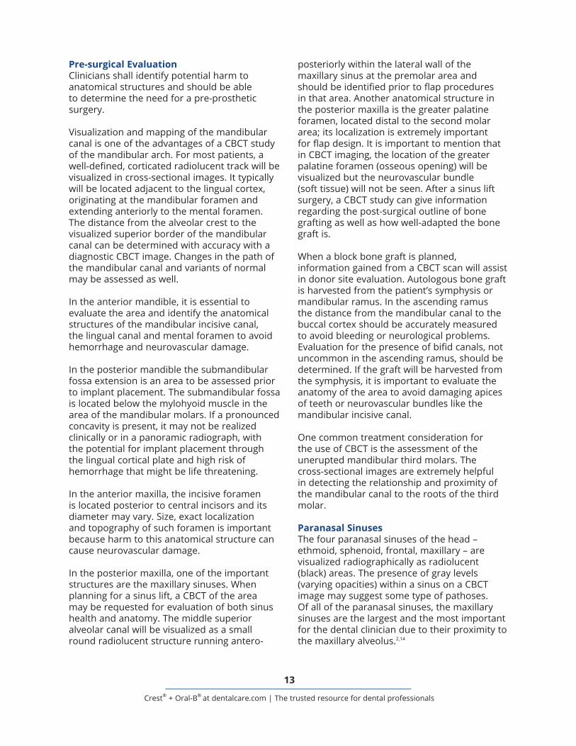
Paranasal SinusesThe four paranasal sinuses of the head – ethmoid, sphenoid, frontal, maxillary – are visualized radiographically as radiolucent (black) areas. The presence of gray levels (varying opacities) within a sinus on a CBCT image may suggest some type of pathoses. Of all of the paranasal sinuses, the maxillary sinuses are the largest and the most important for the dental clinician due to their proximity to the maxillary alveolus.2,14
14
Crest® + Oral-B® at dentalcare.com | The trusted resource for dental professionals
A dome-shaped lesion arising from the floor of the sinus, without mucosal thickening of the rest of the sinus, is characteristic of a retention pseudocyst.2 This common pathologic finding is generally asymptomatic and does not require treatment unless it enlarges to the point where it blocks the ostium.
Sinus lift procedures and foreign body removal are two important indications for requesting a CBCT scan. An antral septum may divide the sinus in two cavities; if not evaluated before surgery, it could cause major complications during the procedure. Visualization and analysis of the size and shape of an antral septum is of clinical importance when a sinus lift is desired in that area.15 Three-dimensional localization of a foreign body within the maxillary sinus by CBCT will assist in determining the best surgical approach for its removal.16
The inner walls of the paranasal sinuses are covered with a thin layer of mucosa, normally less than 1 mm thick and typically not seen radiographically.2 There are several reasons that can lead to mucosal thickening (sinusitis), varying from allergies, foreign bodies, or even odontogenic processes in proximity to the floor of the maxillary sinus (Figure 12). If such an inflammatory process crosses the floor of the sinus, it can create reactional mucosal thickening. The presence of moderate to advanced mucosal thickening (more than 6 mm) will be visualized on a CBCT scan. If maxillary sinuses are included in the field of view of the scan, the clinician must evaluate the health of the sinuses along with the patency of the maxillary ostium (the sinus-draining foramen).2,14 The cause of sinusitis should be identified and treated before a surgical procedure such as a sinus lift is performed in the area.
Figure 12.
15
Crest® + Oral-B® at dentalcare.com | The trusted resource for dental professionals
resorptive defects. Post-treatment indications include evaluation of endodontic treatment complications, such as overextended canal obturations, separated instruments, or perforations. Pre-surgical uses include the localization of root apices and proximity to anatomical structures prior to an apical surgery.20
A CBCT may be beneficial to the clinician for diagnosis in patients with contradictory or non-specific clinical signs and symptoms associated with untreated or previous endodontically treated teeth following evaluation of inconclusive intraoral radiographic findings.
Airway AnalysesThe airway space includes the nasal cavity, nasopharynx, velopharynx, oropharynx and hypopharynx. Large FOV CBCT studies, such as those acquired to assess the craniofacial skeleton for orthodontics and orthognathic surgery, will typically include the airway spaces. In MDCT units where the patient is in a supine (lying with face up) position, gravitational forces on the tongue and soft palate will result in narrowing of the airway space.21 With most CBCT units the patient is in a seating position which does not replicate the sleeping position. The visualized airway is not only influenced by the position of the soft tissue of the neck, it is also influenced by the position of the tongue during acquisition, which can cause the airway to appear narrower.22 CBCT can help identify patients with a high predisposition for obstructive sleep apnea (OSA), although the final diagnosis is typically made through a medical sleep study (polysomnography).
CBCT studies provide only a static image of the airway space, and can be helpful in the detection of anatomical or pathological changes. The airway space should be evaluated systematically for patency and symmetry, with the capability to measure airway dimensions or provide 3D modeling. Although CBCT imaging provides excellent visualization of static airway morphology, it does not provide any direct information on airflow or airway resistance.
Hyperplasia of the nasal turbinates is the most common form of nasal obstruction, and can be caused either by infection or
OrthodonticsCBCT has been used in orthodontics due to the capacity of imaging a large field of view that includes all the landmarks for cephalometric analysis. For analysis of skeletal jaw relationships, the three-dimensional image needs to include the skull base, facial bones, and facial soft tissues. By exporting the DICOM files into specialized software programs, orthodontists are able to perform cephalometric analysis and treatment planning. A CBCT study will be helpful in an orthodontic case with proposed orthognathic surgery.17
Another application of CBCT in the field of orthodontics is to find the exact location of any impacted teeth, along with the relationship of adjacent anatomical structures. This information can assist the clinician in determining the best approach for each case. If root resorption of teeth is present due to impacted teeth, the extent of the resorption may be evaluated through CBCT imaging. The main advantage of CBCT over other dental imaging is the cross-sectional view without superimposition, where the buccolingual position of the roots can be assessed. Despite the benefits and advantages of CBCT studies, it should not be routinely used for all orthodontic patients.17,18
EndodonticsThe preferred CBCT unit is one that allows acquiring a small FOV with a small voxel size; the result will be a radiographic study with high resolution that will allow evaluation of dental pathoses and relationships with adjacent anatomical structures.19 The American Academy of Oral and Maxillofacial Radiology, in conjunction with the American Association of Endodontists, published a position paper in 2015 on the use of CBCT in endodontics. The joint position paper states that intraoral radiographs should be considered the initial imaging modality of choice of the endodontic patient.20 A CBCT should not be made in routine diagnosis or for screening purposes in the absence of endodontic signs.
Uses of a limited FOV CBCT in endodontics include evaluation of complex pulpal morphology or accessory canals, limited dento-alveolar or root fractures, or presence of
16
Crest® + Oral-B® at dentalcare.com | The trusted resource for dental professionals
field of view and small voxel size will provide improved spatial resolution, especially for endodontic purposes.
The advantages of CBCT over panoramic radiographs are 3D analysis, no superimposition or distortion, and the ability to create cross-sectional images. The disadvantages over panoramic imaging are increased radiation dose, acquisition artifacts, and cost.
The advantages of the CBCT over MDCT are faster scan time with less potential for movement artifact, less cost, and less radiation exposure to the patient. A major disadvantage is less soft tissue contrast, which prevents soft tissue assessment.
There are several steps the clinician must check and analyze for each patient and clinical situation:
Region of interest and field of view: Which teeth or anatomical structures are to be visualized? Are the TMJ areas to be included in the scan? Is visualization of both dental arches required, or only one arch? Is partial visualization of the maxillary sinuses enough?
Radiographic Guide: Is a radiographic marker showing the exact location of the desired implant site indicated? Will guided surgery be required? Is the radiographic guide well-adapted? In the cases where the scan will be acquired at a separate location and a radiographic guide will be used, the referring clinician must pre-fit and assess the guide prior to the scan appointment. Also, the clinician should explain to the patient the correct position of the radiographic guide to avoid malposition.
Voxel size: Which voxel size would be the best for this specific situation?
Other: Should the patient’s teeth be in maximum intercuspal occlusion while acquiring the scan? Or with teeth apart? Should cotton rolls be placed between teeth to separate the arches or should a bite registration be used?
chronic inflammation. Other causes of nasal obstruction are nasal septum deviation, nasal polyps, benign tumors (such as osteoma), and malignant tumors (such as squamous cell carcinoma). Neoplasms in the nasopharynx and oropharynx can cause narrowing and/or asymmetry of the airway space. The most common pathological conditions that can affect the airway in children are enlarged pharyngeal and palatine tonsils.2
An airway analysis may be performed prior to orthognathic surgery. Volumetric measurements can be taken for the patient with surgical treatment options considered according to the severity in the position of the jaws.
Temporomandibular Joints (TMJs)A CBCT scan will not demonstrate the position or integrity of the disk, as the disk is not a calcified structure. A CBCT scan that visualizes the TMJs may be evaluated for osseous changes to the mandibular condyle or glenoid fossa of the temporal bone. These osseous changes may result from trauma/fracture, degenerative changes or neoplastic processes.23,24 If demonstration of the soft tissue components of the joint is requested by the clinician, another type of imaging such as magnetic resonance (MR) is recommended. The musculature of the TM joints cannot be assessed by CBCT; the use of a CBCT scan for diagnosis and treatment of myofascial pain disorder or disk displacement is not indicated and thus will not be useful to the clinician.
If osseous evaluation of the TM joints is requested, it is important to choose a scan height to adequately image the entire joint space.23 A drawback of the units using an image intensifier as the detector is that the TM joint spaces are often incompletely imaged or will be visualized at the edge of the spherical scan and prone to distortion.
ConclusionAlthough CBCT is a great tool that provides 3D images, it does not replace standard dental radiographic images and should be utilized as a complementary tool for specific cases, and not for routine cases. CBCT studies with small

17
Crest® + Oral-B® at dentalcare.com | The trusted resource for dental professionals
It is the dentist’s responsibility to critically assess the need for a CBCT study on a case-by-case basis, and to provide an interpretation of the entire data volume. This applies whether the clinician ordered or acquired the CBCT scan, and whether for use within that dental clinic or for use by a referral client.
If an oral and maxillofacial radiologist is to write a report on the scan, it is important to provide enough clinical information (age, gender, significant past medical history, duration of the pain or swelling) to assist in formulating an accurate differential diagnosis and treatment options.
18
Crest® + Oral-B® at dentalcare.com | The trusted resource for dental professionals
Course Test PreviewTo receive Continuing Education credit for this course, you must complete the online test. Please go to: www.dentalcare.com/en-us/professional-education/ce-courses/ce531/start-test
1. An advantage of CBCT over conventional dental imaging is _______________.a. ability to visualize in 3 dimensionsb. decreased patient exposurec. decreased cost to patientd. ability to see soft tissue
2. The advantages of CBCT over a medical MDCT are _______________.a. less radiation exposure to patientb. faster scanc. less cost for the scand. All of the above.
3. CBCT machines may be classified based upon the _______________.a. shape of the x-ray beamb. field of viewc. exposure timed. kilovoltage
4. Modifying which factor would decrease radiation patient to the patient during a CBCT scan?a. Decreasing the field of viewb. Increasing the region of interestc. Increasing the scan timed. Decreasing the voxel size
5.. Voxel size in CBCT image acquisition _______________.a. may be modified by post-processingb. is pre-selected by patient sizec. is the same as for a medical MSCTd. is isotrophic in nature
6. Selection of an increased voxel size for a CBCT scan _______________.a. affects measurement accuracyb. affects structural relationshipsc. decreases image resolutiond. increases image detail
7. The interpretation of the CBCT image volume should be _______________.a. systematic, treatment-directedb. systematic, comprehensivec. focused, limitedd. focused, symptom-directed
8. Which view is considered a reformatted image useful in implant planning?a. Axialb. Coronalc. Sagittald. Cross-sectional

19
Crest® + Oral-B® at dentalcare.com | The trusted resource for dental professionals
9. “Beam hardening” artifacts in CBCT images can occur as a result of _______________.a. patient movement during the acquisitionb. superimposition of structuresc. dense, radiopaque materials within the area scannedd. too low of exposure setting
10. A CBCT scan may need to be reacquired if _______________.a. the patient’s head was tipped resulting in distortionb. double contours of bone are seen on the imagesc. the patient continued to breath during the scan acquisitiond. the voxel size was too small
11. A CBCT scan would be potentially helpful for which assessment?a. Locating an accessory canal during endodontic treatmentb. Determining a crack in enamel for a patient with pain on bitingc. Noting disk displacement in the TMJ aread. Finding caries beneath a dental restoration or cast crown
12. What type of findings can be visualized in a CBCT image?a. Mucous plug in salivary ductb. Hematoma at an injection sitec. Asymmetry or interruption of airway spaced. Salivary gland outlines within the soft tissue
13. In a scan of the temporomandibular joints, which could be potentially confirmed or denied on a CBCT scan?a. Disk displacementb. Edema following traumac. Condylar neck fractured. Soft tissue tumor
14. CBCT scans are indicated in the treatment planning for routine cases in _______________.a. orthodonticsb. third molar extractionsc. endodonticsd. All of the above.e. None of the above.
15. What is the dentist’s interpretive responsibility for a large FOV CBCT scan?a. Teeth and alveolar boneb. Maxilla and mandiblec. Dental arches and maxillary sinusesd. All areas imaged within the scan
20
Crest® + Oral-B® at dentalcare.com | The trusted resource for dental professionals
References1. Abramovitch K, Rice DD. Basic principles of cone beam computed tomography. Dent Clin North
Am. 2014 Jul;58(3):463-84. doi: 10.1016/j.cden.2014.03.002.2. Gonzalez SM. Interpretation basics of cone beam computed tomography. Ames, IA. Wiley
Blackwell. 2014.3. Scherer MD. Presurgical implant-site assessment and restoratively driven digital planning. Dent
Clin North Am. 2014 Jul;58(3):561-95. doi: 10.1016/j.cden.2014.04.002.4. White SC, Pharoah MJ. Oral radiology: principles and interpretation. St. Louis, Mo. Mosby/
Elsevier. 2014.5. Scarfe WC, Li Z, Aboelmaaty W, et al. Maxillofacial cone beam computed tomography:
essence, elements and steps to interpretation. Aust Dent J. 2012 Mar;57 Suppl 1:46-60. doi: 10.1111/j.1834-7819.2011.01657.x.
6. Scarfe WC, Farman AG. What is cone-beam CT and how does it work? Dent Clin North Am. 2008 Oct;52(4):707-30, v. doi: 10.1016/j.cden.2008.05.005.
7. Farman AG, Feuerstein P, Levato CM. Using CBCT in the general practice. Compend Contin Educ Dent. 2011 Mar;32(2):14-6.
8. Angelopoulos C, Scarfe WC, Farman AG. A comparison of maxillofacial CBCT and medical CT. Atlas Oral Maxillofac Surg Clin North Am. 2012 Mar;20(1):1-17. doi: 10.1016/j.cxom.2011.12.008.
9. Brown J, Jacobs R, Levring Jäghagen E, et al. Basic training requirements for the use of dental CBCT by dentists: a position paper prepared by the European Academy of DentoMaxilloFacial Radiology. Dentomaxillofacial Radiology. 2014;43(1):20130291. doi:10.1259/dmfr.20130291.
10. Miles DA. Atlas of cone beam imaging for dental applications, 2nd ed. Chicago, IL. Quintessence Pub. 2013.
11. Pauwels R. Cone beam CT for dental and maxillofacial imaging: dose matters. Radiat Prot Dosimetry. 2015 Jul;165(1-4):156-61. doi: 10.1093/rpd/ncv057. Epub 2015 Mar 23.
12. Tyndall DA, Brooks SL. Selection criteria for dental implant site imaging: a position paper of the American Academy of Oral and Maxillofacial radiology. Oral Surg Oral Med Oral Pathol Oral Radiol Endod. 2000 May;89(5):630-7.
13. Makins SR. Artifacts interfering with interpretation of cone beam computed tomography images. Dent Clin North Am. 2014 Jul;58(3):485-95. doi: 10.1016/j.cden.2014.04.007.
14. Angelopoulos C. Anatomy of the maxillofacial region in the three planes of section. Dent Clin North Am. 2014 Jul;58(3):497-521. doi: 10.1016/j.cden.2014.03.001.
15. Bornstein MM, Seiffert C, Maestre-Ferrín L, et al. An Analysis of Frequency, Morphology, and Locations of Maxillary Sinus Septa Using Cone Beam Computed Tomography. Int J Oral Maxillofac Implants. 2016 Mar-Apr;31(2):280-7. doi: 10.11607/jomi.4188. Epub 2015 Oct 16.
16. Lari SS, Shokri A, Hosseinipanah SM, et al. Comparative Sensitivity Assessment of Cone Beam Computed Tomography and Digital Radiography for detecting Foreign Bodies. J Contemp Dent Pract. 2016 Mar 1;17(3):224-9.
17. Kau CH, Li JL, Li Q, et al. Update on cone beam technology and orthodontic analysis. Dent Clin North Am. 2014 Jul;58(3):653-69. doi: 10.1016/j.cden.2014.04.004.
18. Kapila SD, Nervina JM. CBCT in orthodontics: assessment of treatment outcomes and indications for its use. Dentomaxillofac Radiol. 2015;44(1):20140282. doi: 10.1259/dmfr.20140282.
19. Todd R. Cone beam computed tomography updated technology for endodontic diagnosis. Dent Clin North Am. 2014 Jul;58(3):523-43. doi: 10.1016/j.cden.2014.03.003.
20. AAE and AAOMR Joint Position Statement: Use of Cone Beam Computed Tomography in Endodontics 2015 Update. Oral Surg Oral Med Oral Pathol Oral Radiol. 2015 Oct;120(4):508-12. doi: 10.1016/j.oooo.2015.07.033. Epub 2015 Aug 3.
21. Tikku T, Khanna R, Sachan K, et al. Dimensional and volumetric analysis of the oropharyngeal region in obstructive sleep apnea patients: A cone beam computed tomography study. Dental Research Journal. 2016;13(5):396-404.
22. Guijarro-Martínez R, Swennen GR. Cone-beam computerized tomography imaging and analysis of the upper airway: a systematic review of the literature. Int J Oral Maxillofac Surg. 2011 Nov;40(11):1227-37. doi: 10.1016/j.ijom.2011.06.017. Epub 2011 Jul 20.

21
Crest® + Oral-B® at dentalcare.com | The trusted resource for dental professionals
23. Barghan S, Tetradis S, Mallya S. Application of cone beam computed tomography for assessment of the temporomandibular joints. Aust Dent J. 2012 Mar;57 Suppl 1:109-18. doi: 10.1111/j.1834-7819.2011.01663.x.
24. Cone beam computed tomographic findings in temporomandibular joint disorders. Alpha Omegan. 2010 Jun;103(2):68-78.
Additional Resources• Basic Principles for Use of Dental Cone Beam CT. The SEDENTEXCT-EADMFR Collaboration.
Accessed October 23, 2017.
About the Authors
Diane J. Flint, DDS, MS, Diplomate ABOMR, Diplomate ABGDDr. Diane J. Flint is Associate Professor and Director of the Oral and Maxillofacial Radiology Residency Program at Texas A&M College of Dentistry in Dallas, Texas. She is a diplomate of the American Board of Oral and Maxillofacial Radiology and the American Board of General Dentistry. Dr. Flint served in the U.S. Air Force for 20 years, and was appointed as the Military Consultant to the Air Force Surgeon General for Oral and Maxillofacial Radiology from 2004-2006. She received the Charles Craig Teaching Award in 2012 from the Omicron Kappa Upsilon National Dental Honor Society, as well as the Distinguished
Teaching and Teaching Excellence Awards from Texas A&M College of Dentistry in 2011 and 2016, respectively.
Email: [email protected]
Regina Casian Ruiz Velasco, DDS, Post-doctoral resident in OMRDr. Regina Casian Ruiz Velasco is a 2017 graduate of the Oral and Maxillofacial Radiology Residency at Texas A&M College of Dentistry, and received a certificate in Prosthodontics from Universidad Intercontinental in Mexico City, Mexico, in 2013. Dr. Casian has presented diverse continuing education courses in Mexico and the U.S. in the field of prosthodontics, restorative dentistry, dental implants and oral and maxillofacial radiology.
Email: [email protected]