Embed Size (px)
Citation preview
CE EMC TEST REPORT Report No. : C362802
SPORTON International Inc.TEL : 886-2-2696-2468FAX : 886-2-2696-2255
CE EMC TEST REPORT
according to
EN 301 489-1 V1.4.1 (2002-08) and EN 301 489-17 V1.2.1 (2002-08)
Equipment : WIRELESS 11B PCI CARD
Model No. : PC11B2, MS-6828
Applicant : Micro-Star Int’l Co., Ltd. No. 69, Li-De St., Jung-He City, Taipei Hsien, Taiwan
The test result refers exclusively to the test presented test model / sample. Without written approval of SPORTON International Inc., the test report shall not be reproduced except
in full. This test report is only applicable to European Community.
SPORTON International Inc. 6F, No. 106, Sec. 1, Hsin Tai Wu Rd., Hsi Chih, Taipei Hsien, Taiwan, R.O.C.
CE EMC TEST REPORT Report No. : C362802
SPORTON International Inc. Page Number : i TEL : 886-2-2696-2468 Issued Date : Jul. 18, 2003 FAX : 886-2-2696-2255
Table of Contents History of this test report....................................................................................................................................ii CERTIFICATE OF COMPLIANCE........................................................................................................................1 1. General Description of Equipment under Test.............................................................................................2
1.1 Applicant..........................................................................................................................................................................................2 1.2 Manufacturer ...................................................................................................................................................................................2 1.3 Basic Description of Equipment under Test ....................................................................................................................................2 1.4 Feature of Equipment under Test ...................................................................................................................................................3
2. Test Configuration of Equipment under Test ...............................................................................................4 2.1 Test Manner ....................................................................................................................................................................................4 2.2 Description of Test System .............................................................................................................................................................4
3. Test Software ...................................................................................................................................................7 4. General Information of Test............................................................................................................................8
4.1 Test Facility .....................................................................................................................................................................................8 4.2 Test Voltage ....................................................................................................................................................................................8 4.3 Standard for Methods of Measurement...........................................................................................................................................8 4.4 Test in Compliance with ..................................................................................................................................................................8 4.5 Frequency Range Investigated .......................................................................................................................................................8 4.6 Test Distance ..................................................................................................................................................................................8 4.7 Summary of Test Results ................................................................................................................................................................9
5. Test of Conducted Powerline .......................................................................................................................10 5.1 Description of Major Test Instruments ..........................................................................................................................................10 5.2 Test Procedures ............................................................................................................................................................................11 5.3 Typical Test Setup Layout of Conducted Powerline .....................................................................................................................12 5.4 Test Result of AC Powerline Conducted Emission .......................................................................................................................13 5.5 Photographs of Conducted Powerline Test Configuration ............................................................................................................15
6. Test of Radiated Emission............................................................................................................................16 6.1 Description of Major Test Instruments ..........................................................................................................................................16 6.2 Test Procedures ............................................................................................................................................................................17 6.3 Typical Test Setup Layout of Radiated Emission..........................................................................................................................18 6.4 Test Result of Radiated Emission .................................................................................................................................................19 6.5 Photographs of Radiated Emission Test Configuration ................................................................................................................23
7. Electrostatic Discharge Immunity Test (ESD) ............................................................................................24 7.1 Test setup......................................................................................................................................................................................24 7.2 Test Setup for Tests Performed in Laboratory ..............................................................................................................................25 7.3 ESD Test Procedure .....................................................................................................................................................................26 7.4 Test Severity Levels ......................................................................................................................................................................27 7.5 Test Points ....................................................................................................................................................................................28 7.6 Photographs of Electrostatic Discharge Immunity Test ................................................................................................................29
8. Radio Frequency Electromagnetic Field Immunity Test (RS)...................................................................30 8.1 Test setup......................................................................................................................................................................................30 8.2 Test Procedure..............................................................................................................................................................................31 8.3 Test Severity Levels ......................................................................................................................................................................31 8.4 Photographs of Radio Frequency Electromagnetic Field Immunity Test ......................................................................................32
9. List of Measuring Equipment Used .............................................................................................................33 10. Declaration of Conformity and the CE Mark .............................................................................................35 Appendix A. Photographs of EUT.......................................................................................................... A1 ~ A6
CE EMC TEST REPORT Report No. : C362802
SPORTON International Inc. Page Number : ii TEL : 886-2-2696-2468 Issued Date : Jul. 18, 2003 FAX : 886-2-2696-2255
History of this test report Original Report Issue Date: Jul. 18, 2003 ■ No additional attachment. □ Additional attachment were issued as following record:
Attachment No. Issue Date Description
CE EMC TEST REPORT Report No. : C362802
SPORTON International Inc. Page Number : 1 of 35 TEL : 886-2-2696-2468 Issued Date : Jul. 18, 2003 FAX : 886-2-2696-2255
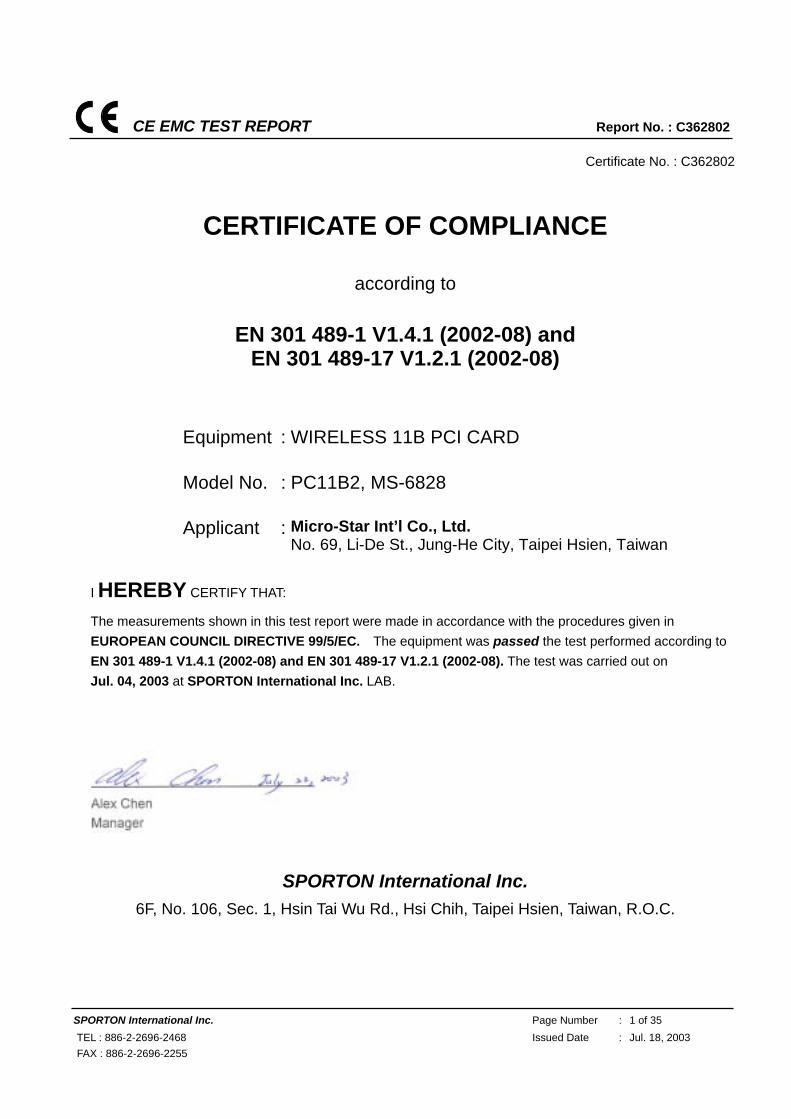
Certificate No. : C362802
CERTIFICATE OF COMPLIANCE
according to
EN 301 489-1 V1.4.1 (2002-08) and EN 301 489-17 V1.2.1 (2002-08)
Equipment : WIRELESS 11B PCI CARD
Model No. : PC11B2, MS-6828
Applicant : Micro-Star Int’l Co., Ltd. No. 69, Li-De St., Jung-He City, Taipei Hsien, Taiwan
I HEREBY CERTIFY THAT:
The measurements shown in this test report were made in accordance with the procedures given in EUROPEAN COUNCIL DIRECTIVE 99/5/EC. The equipment was passed the test performed according to EN 301 489-1 V1.4.1 (2002-08) and EN 301 489-17 V1.2.1 (2002-08). The test was carried out on Jul. 04, 2003 at SPORTON International Inc. LAB.
SPORTON International Inc.
6F, No. 106, Sec. 1, Hsin Tai Wu Rd., Hsi Chih, Taipei Hsien, Taiwan, R.O.C.
CE EMC TEST REPORT Report No. : C362802
SPORTON International Inc. Page Number : 2 of 35 TEL : 886-2-2696-2468 Issued Date : Jul. 18, 2003 FAX : 886-2-2696-2255
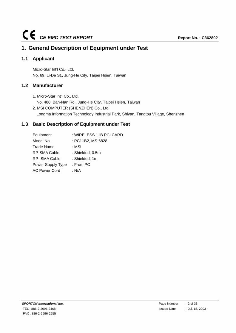
1. General Description of Equipment under Test
1.1 Applicant
Micro-Star Int’l Co., Ltd. No. 69, Li-De St., Jung-He City, Taipei Hsien, Taiwan
1.2 Manufacturer
1. Micro-Star Int’l Co., Ltd. No. 488, Ban-Nan Rd., Jung-He City, Taipei Hsien, Taiwan
2. MSI COMPUTER (SHENZHEN) Co., Ltd. Longma Information Technology Industrial Park, Shiyan, Tangtou Village, Shenzhen
1.3 Basic Description of Equipment under Test
Equipment : WIRELESS 11B PCI CARD Model No. : PC11B2, MS-6828 Trade Name : MSI RP-SMA Cable : Shielded, 0.5m RP- SMA Cable : Shielded, 1m Power Supply Type : From PC AC Power Cord : N/A
CE EMC TEST REPORT Report No. : C362802
SPORTON International Inc. Page Number : 3 of 35 TEL : 886-2-2696-2468 Issued Date : Jul. 18, 2003 FAX : 886-2-2696-2255
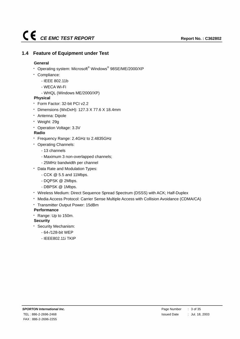
1.4 Feature of Equipment under Test
General Operating system: Microsoft® Windows® 98SE/ME/2000/XP Compliance:
- IEEE 802.11b - WECA Wi-Fi - WHQL (Windows ME/2000/XP)
Physical Form Factor: 32-bit PCI v2.2 Dimensions (WxDxH): 127.3 X 77.6 X 18.4mm Antenna: Dipole Weight: 29g Operation Voltage: 3.3V Radio Frequency Range: 2.4GHz to 2.4835GHz Operating Channels:
- 13 channels - Maximum 3 non-overlapped channels; - 25MHz bandwidth per channel
Data Rate and Modulation Types: - CCK @ 5.5 and 11Mbps. - DQPSK @ 2Mbps. - DBPSK @ 1Mbps.
Wireless Medium: Direct Sequence Spread Spectrum (DSSS) with ACK; Half-Duplex Media Access Protocol: Carrier Sense Multiple Access with Collision Avoidance (CDMA/CA) Transmitter Output Power: 15dBm Performance Range: Up to 150m. Security Security Mechanism:
- 64-/128-bit WEP - IEEE802.11i TKIP
CE EMC TEST REPORT Report No. : C362802
SPORTON International Inc. Page Number : 4 of 35 TEL : 886-2-2696-2468 Issued Date : Jul. 18, 2003 FAX : 886-2-2696-2255
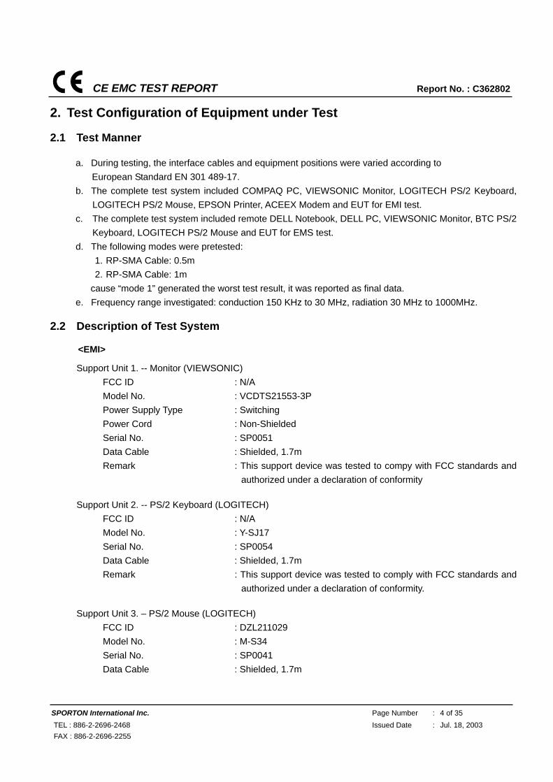
2. Test Configuration of Equipment under Test
2.1 Test Manner
a. During testing, the interface cables and equipment positions were varied according to European Standard EN 301 489-17.
b. The complete test system included COMPAQ PC, VIEWSONIC Monitor, LOGITECH PS/2 Keyboard, LOGITECH PS/2 Mouse, EPSON Printer, ACEEX Modem and EUT for EMI test.
c. The complete test system included remote DELL Notebook, DELL PC, VIEWSONIC Monitor, BTC PS/2 Keyboard, LOGITECH PS/2 Mouse and EUT for EMS test.
d. The following modes were pretested: 1. RP-SMA Cable: 0.5m 2. RP-SMA Cable: 1m
cause “mode 1” generated the worst test result, it was reported as final data. e. Frequency range investigated: conduction 150 KHz to 30 MHz, radiation 30 MHz to 1000MHz.
2.2 Description of Test System
<EMI>
Support Unit 1. -- Monitor (VIEWSONIC) FCC ID : N/A Model No. : VCDTS21553-3P Power Supply Type : Switching Power Cord : Non-Shielded Serial No. : SP0051 Data Cable : Shielded, 1.7m Remark : This support device was tested to compy with FCC standards and
authorized under a declaration of conformity Support Unit 2. -- PS/2 Keyboard (LOGITECH)
FCC ID : N/A Model No. : Y-SJ17 Serial No. : SP0054 Data Cable : Shielded, 1.7m Remark : This support device was tested to comply with FCC standards and
authorized under a declaration of conformity.
Support Unit 3. – PS/2 Mouse (LOGITECH) FCC ID : DZL211029 Model No. : M-S34 Serial No. : SP0041 Data Cable : Shielded, 1.7m
CE EMC TEST REPORT Report No. : C362802
SPORTON International Inc. Page Number : 5 of 35 TEL : 886-2-2696-2468 Issued Date : Jul. 18, 2003 FAX : 886-2-2696-2255
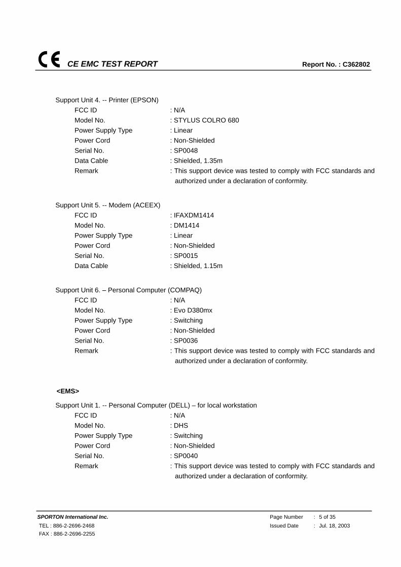
Support Unit 4. -- Printer (EPSON) FCC ID : N/A Model No. : STYLUS COLRO 680 Power Supply Type : Linear Power Cord : Non-Shielded Serial No. : SP0048 Data Cable : Shielded, 1.35m Remark : This support device was tested to comply with FCC standards and
authorized under a declaration of conformity.
Support Unit 5. -- Modem (ACEEX) FCC ID : IFAXDM1414 Model No. : DM1414 Power Supply Type : Linear Power Cord : Non-Shielded Serial No. : SP0015 Data Cable : Shielded, 1.15m
Support Unit 6. – Personal Computer (COMPAQ) FCC ID : N/A Model No. : Evo D380mx Power Supply Type : Switching Power Cord : Non-Shielded Serial No. : SP0036 Remark : This support device was tested to comply with FCC standards and
authorized under a declaration of conformity. <EMS>
Support Unit 1. -- Personal Computer (DELL) – for local workstation FCC ID : N/A Model No. : DHS Power Supply Type : Switching Power Cord : Non-Shielded Serial No. : SP0040 Remark : This support device was tested to comply with FCC standards and
authorized under a declaration of conformity.
CE EMC TEST REPORT Report No. : C362802
SPORTON International Inc. Page Number : 6 of 35 TEL : 886-2-2696-2468 Issued Date : Jul. 18, 2003 FAX : 886-2-2696-2255
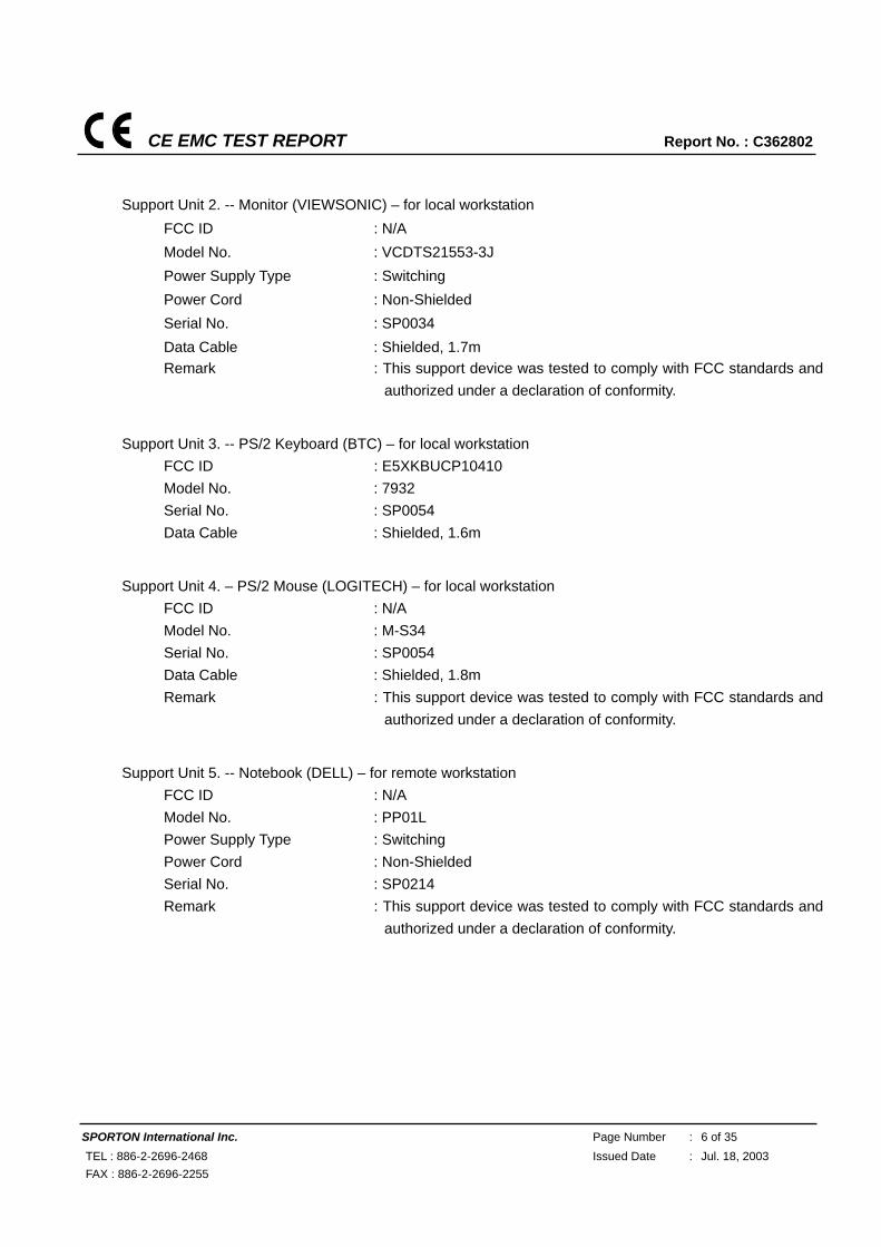
Support Unit 2. -- Monitor (VIEWSONIC) – for local workstation FCC ID : N/A Model No. : VCDTS21553-3J Power Supply Type : Switching Power Cord : Non-Shielded Serial No. : SP0034 Data Cable : Shielded, 1.7m Remark : This support device was tested to comply with FCC standards and
authorized under a declaration of conformity.
Support Unit 3. -- PS/2 Keyboard (BTC) – for local workstation FCC ID : E5XKBUCP10410 Model No. : 7932 Serial No. : SP0054 Data Cable : Shielded, 1.6m
Support Unit 4. – PS/2 Mouse (LOGITECH) – for local workstation FCC ID : N/A Model No. : M-S34 Serial No. : SP0054 Data Cable : Shielded, 1.8m Remark : This support device was tested to comply with FCC standards and
authorized under a declaration of conformity.
Support Unit 5. -- Notebook (DELL) – for remote workstation FCC ID : N/A Model No. : PP01L Power Supply Type : Switching Power Cord : Non-Shielded Serial No. : SP0214 Remark : This support device was tested to comply with FCC standards and
authorized under a declaration of conformity.
CE EMC TEST REPORT Report No. : C362802
SPORTON International Inc. Page Number : 7 of 35 TEL : 886-2-2696-2468 Issued Date : Jul. 18, 2003 FAX : 886-2-2696-2255
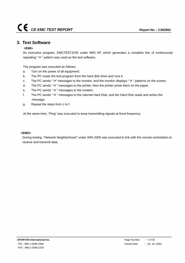
3. Test Software
<EMI> An executive program, EMCTEST.EXE under WIN XP, which generates a complete line of continuously repeating “ H “ pattern was used as the test software. The program was executed as follows: a. Turn on the power of all equipment. b. The PC reads the test program from the hard disk drive and runs it. c. The PC sends “ H“ messages to the monitor, and the monitor displays “ H “ patterns on the screen. d. The PC sends “ H “ messages to the printer, then the printer prints them on the paper. e. The PC sends “ H “ messages to the modem. f. The PC sends “ H ” messages to the internal Hard Disk, and the Hard Disk reads and writes the
message. g. Repeat the steps from c to f. At the same time, “Ping” was executed to keep transmitting signals at fixed frequency.
<EMS> During testing, "Network Neighborhood" under WIN 2000 was executed to link with the remote workstation to receive and transmit data.
CE EMC TEST REPORT Report No. : C362802
SPORTON International Inc. Page Number : 8 of 35 TEL : 886-2-2696-2468 Issued Date : Jul. 18, 2003 FAX : 886-2-2696-2255
4. General Information of Test
4.1 Test Facility
<EMI> Test Site Location : No. 52, Hwa Ya 1st Rd., Hwa Ya Technology Park, Kwei-Shan Hsiag, Tao Yuan Hsien, Taiwan, R.O.C. TEL : 886-3-327-3456 FAX : 886-3-318-0055 Test Site No. : CO01-HY, 10CH02-HY <EMS> Test Site Location : No. 52, Hwa Ya 1St Road, Hwa Ya Technology Park,
Kwei-Shan Hsiang, TaoYuan Hsien, Taiwan, R.O.C. TEL: 886-3-3273456 FAX: 886-3-3180055
4.2 Test Voltage
230V/50Hz
4.3 Standard for Methods of Measurement
EMI Test : European Standard EN 301 489-1 V.1.4.1 (2002-08) : European Standard EN 301 489-17 V.1.2.1 (2002-08)
EMS Test : European Standard EN 301 489-1 V.1.4.1 (2002-08) : European Standard EN 301 489-17 V.1.2.1 (2002-08)
(ESD: IEC 61000-4-2, RS: IEC 61000-4-3)
4.4 Test in Compliance with
EMI Test : European Standard EN 301 489-1 V.1.4.1 (2002-08) : European Standard EN 301 489-17 V.1.2.1 (2002-08)
EMS Test : European Standard EN 301 489-1 V.1.4.1 (2002-08) : European Standard EN 301 489-17 V.1.2.1 (2002-08)
(ESD: IEC 61000-4-2, RS: IEC 61000-4-3)
4.5 Frequency Range Investigated
a. Conducted emission test: from 150 kHz to 30 MHz b. Radiated emission test: from 30 MHz to 1,000 MHz c. Radio frequency electromagnetic field immunity test: 80-1000 MHz, 1400-2000 MHz.
4.6 Test Distance
a. The test distance of radiated emission test from antenna to EUT is 10 M. b. The test distance of radio frequency electromagnetic field immunity test from antenna to EUT is 3 M.
CE EMC TEST REPORT Report No. : C362802
SPORTON International Inc. Page Number : 9 of 35 TEL : 886-2-2696-2468 Issued Date : Jul. 18, 2003 FAX : 886-2-2696-2255
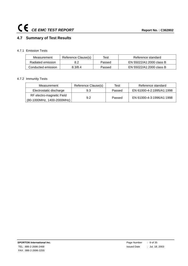
4.7 Summary of Test Results
4.7.1 Emission Tests
Measurement Reference Clause(s) Test Reference standard Radiated emission 8.2 Passed EN 55022/A1:2000 class B
Conducted emission 8.3/8.4 Passed EN 55022/A1:2000 class B
4.7.2 Immunity Tests
Measurement Reference Clause(s) Test Reference standard Electrostatic discharge 9.3 Passed EN 61000-4-2:1995/A1:1998
RF electro-magnetic Field (80-1000MHz, 1400-2000MHz)
9.2 Passed EN 61000-4-3:1996/A1:1998
CE EMC TEST REPORT Report No. : C362802
SPORTON International Inc. Page Number : 10 of 35 TEL : 886-2-2696-2468 Issued Date : Jul. 18, 2003 FAX : 886-2-2696-2255
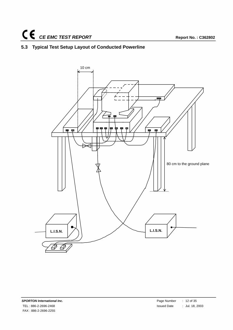
5. Test of Conducted Powerline
Conducted Emissions were measured from 150 kHz to 30 MHz with a bandwidth of 9 kHz and return leads of
the EUT according to the methods defined in European Standard EN 301 489-17. The EUT was placed on a
nonmetallic stand in a shielded room 0.8 meters above the ground plane as shown in section 5.3. The
interface cables and equipment positioning were varied within limits of reasonable applications to determine
the position producing maximum conducted emissions.
5.1 Description of Major Test Instruments
Test Receiver (R&S ESCS 30)
Attenuation 10 dB
Start Frequency 0.15 MHz Stop Frequency 30 MHz
IF Bandwidth 9 KHz
CE EMC TEST REPORT Report No. : C362802
SPORTON International Inc. Page Number : 11 of 35 TEL : 886-2-2696-2468 Issued Date : Jul. 18, 2003 FAX : 886-2-2696-2255
5.2 Test Procedures
a. The EUT was placed on a desk 0.8 meters height from the metal ground plane and 0.4 meter from the
conducting wall of the shielding room and it was kept at least 0.8 meters from any other grounded
conducting surface.
b. Connect EUT to the power mains through a line impedance stabilization network (LISN).
c. Connect Telecommunication port to ISN (Impedance Stabilization Network)
d. All the support units are connect to the other LISN.
e. The LISN provides 50 ohm coupling impedance for the measuring instrument.
f. The CISPR states that a 50 ohm, 50 microhenry LISN should be used.
g. Both sides of AC line were checked for maximum conducted interference.
h. The frequency range from 150 kHz to 30 MHz was searched.
i. Set the test-receiver system to Peak Detect Function and Specified Bandwidth with Maximum Hold
Mode.
CE EMC TEST REPORT Report No. : C362802
SPORTON International Inc. Page Number : 12 of 35 TEL : 886-2-2696-2468 Issued Date : Jul. 18, 2003 FAX : 886-2-2696-2255
5.3 Typical Test Setup Layout of Conducted Powerline
L.I.S.N.
10 cm
80 cm to the ground plane
L.I.S.N.
CE EMC TEST REPORT Report No. : C362802
SPORTON International Inc. Page Number : 13 of 35 TEL : 886-2-2696-2468 Issued Date : Jul. 18, 2003 FAX : 886-2-2696-2255
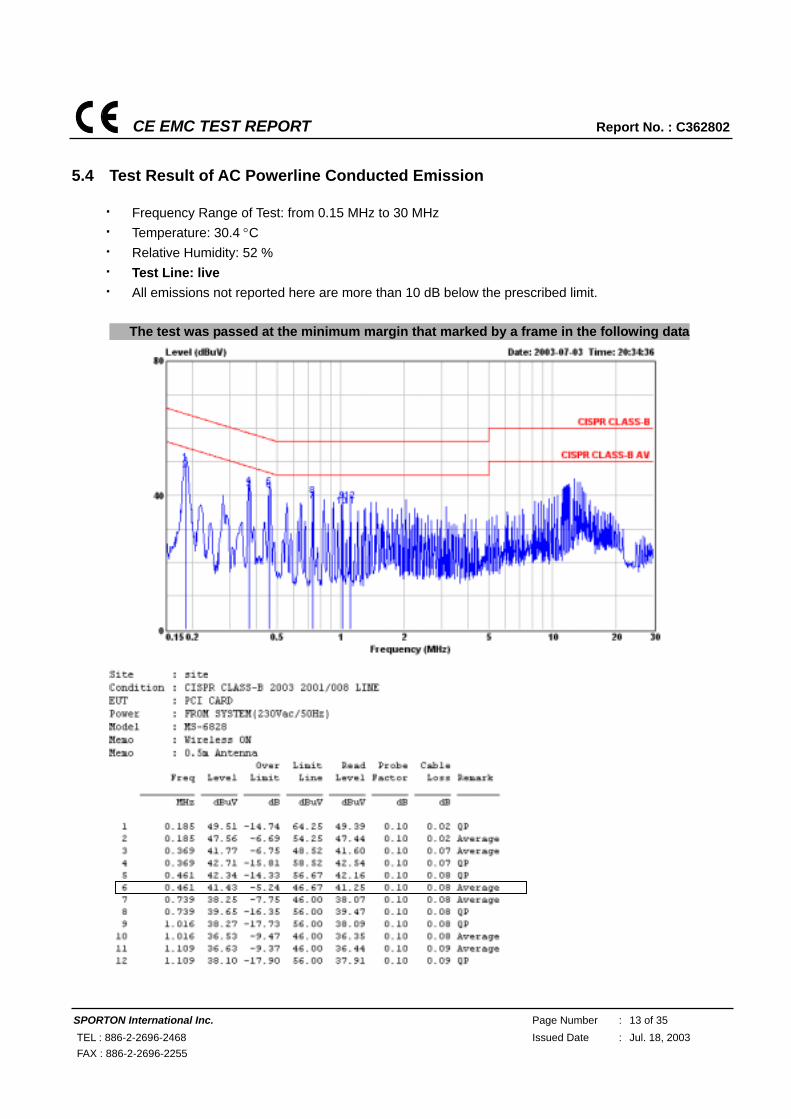
5.4 Test Result of AC Powerline Conducted Emission
Frequency Range of Test: from 0.15 MHz to 30 MHz Temperature: 30.4 °C Relative Humidity: 52 % Test Line: live All emissions not reported here are more than 10 dB below the prescribed limit.
■ The test was passed at the minimum margin that marked by a frame in the following data
CE EMC TEST REPORT Report No. : C362802
SPORTON International Inc. Page Number : 14 of 35 TEL : 886-2-2696-2468 Issued Date : Jul. 18, 2003 FAX : 886-2-2696-2255
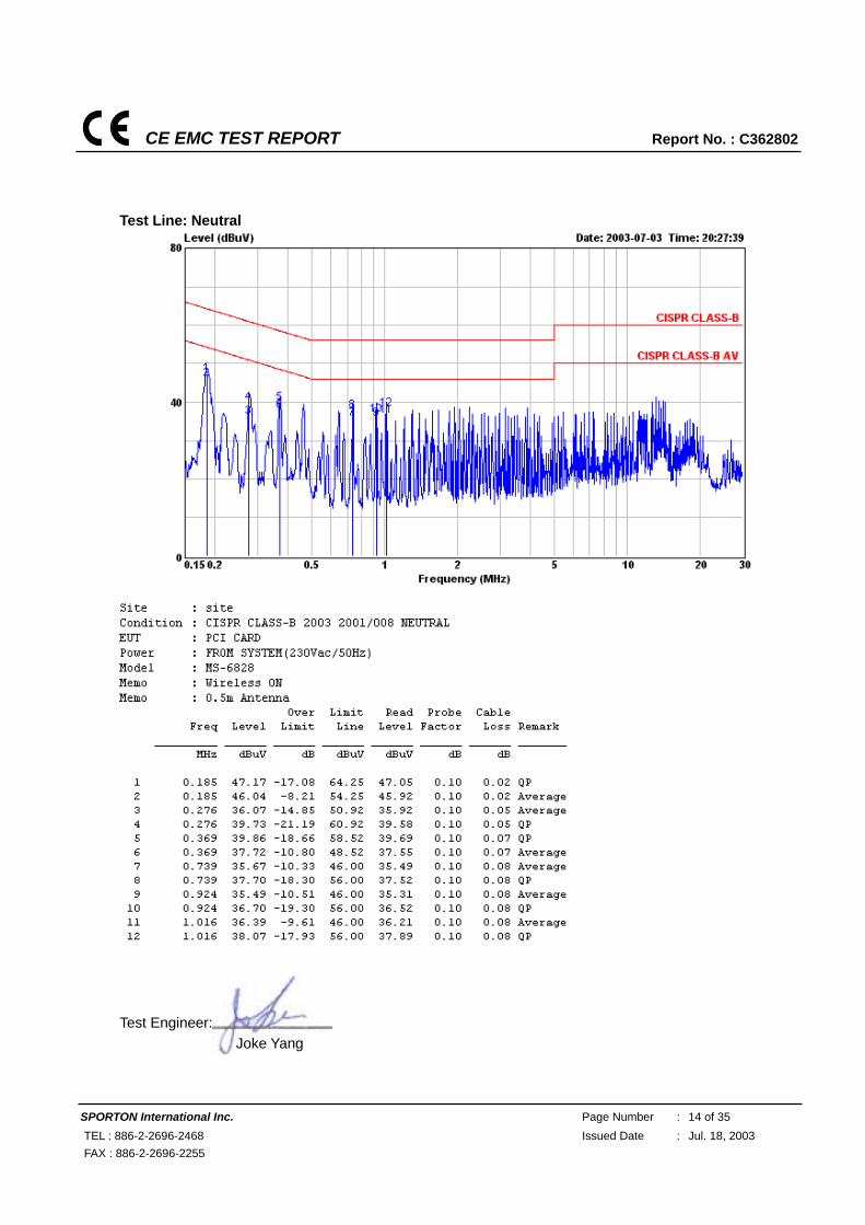
Test Line: Neutral
Test Engineer: Joke Yang
CE EMC TEST REPORT Report No. : C362802
SPORTON International Inc. Page Number : 15 of 35 TEL : 886-2-2696-2468 Issued Date : Jul. 18, 2003 FAX : 886-2-2696-2255
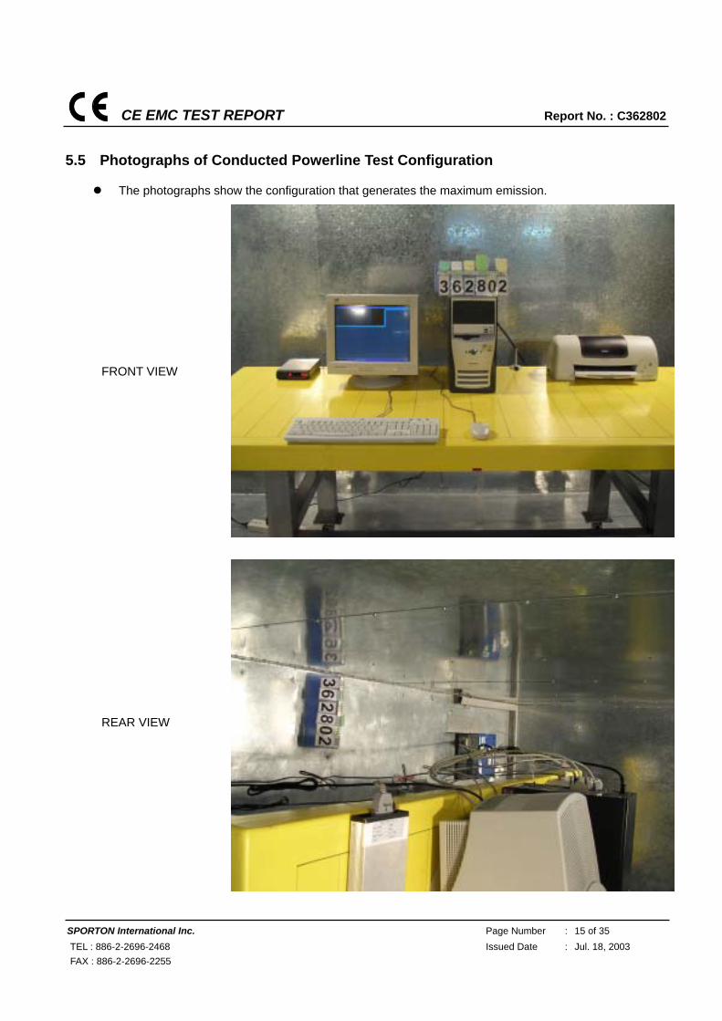
5.5 Photographs of Conducted Powerline Test Configuration
The photographs show the configuration that generates the maximum emission.
FRONT VIEW
REAR VIEW
CE EMC TEST REPORT Report No. : C362802
SPORTON International Inc. Page Number : 16 of 35 TEL : 886-2-2696-2468 Issued Date : Jul. 18, 2003 FAX : 886-2-2696-2255
6. Test of Radiated Emission
Radiated emissions from 30 MHz to 1000 MHz were measured with a bandwidth of 120 kHz according to
the methods defines in European Standard EN 301 489-17. The EUT was placed on a nonmetallic stand,
0.8 meter above the ground plane, as shown in section 6.3. The interface cables and equipment positions
were varied within limits of reasonable applications to determine the positions producing maximum radiated
emissions.
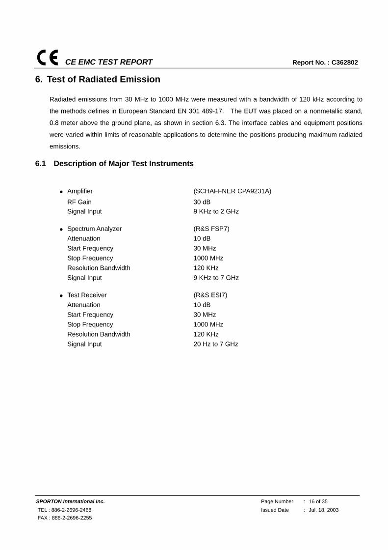
6.1 Description of Major Test Instruments
Amplifier (SCHAFFNER CPA9231A)
RF Gain 30 dB Signal Input 9 KHz to 2 GHz
Spectrum Analyzer (R&S FSP7)
Attenuation 10 dB Start Frequency 30 MHz Stop Frequency 1000 MHz Resolution Bandwidth 120 KHz Signal Input 9 KHz to 7 GHz
Test Receiver (R&S ESI7)
Attenuation 10 dB Start Frequency 30 MHz Stop Frequency 1000 MHz Resolution Bandwidth 120 KHz Signal Input 20 Hz to 7 GHz
CE EMC TEST REPORT Report No. : C362802
SPORTON International Inc. Page Number : 17 of 35 TEL : 886-2-2696-2468 Issued Date : Jul. 18, 2003 FAX : 886-2-2696-2255
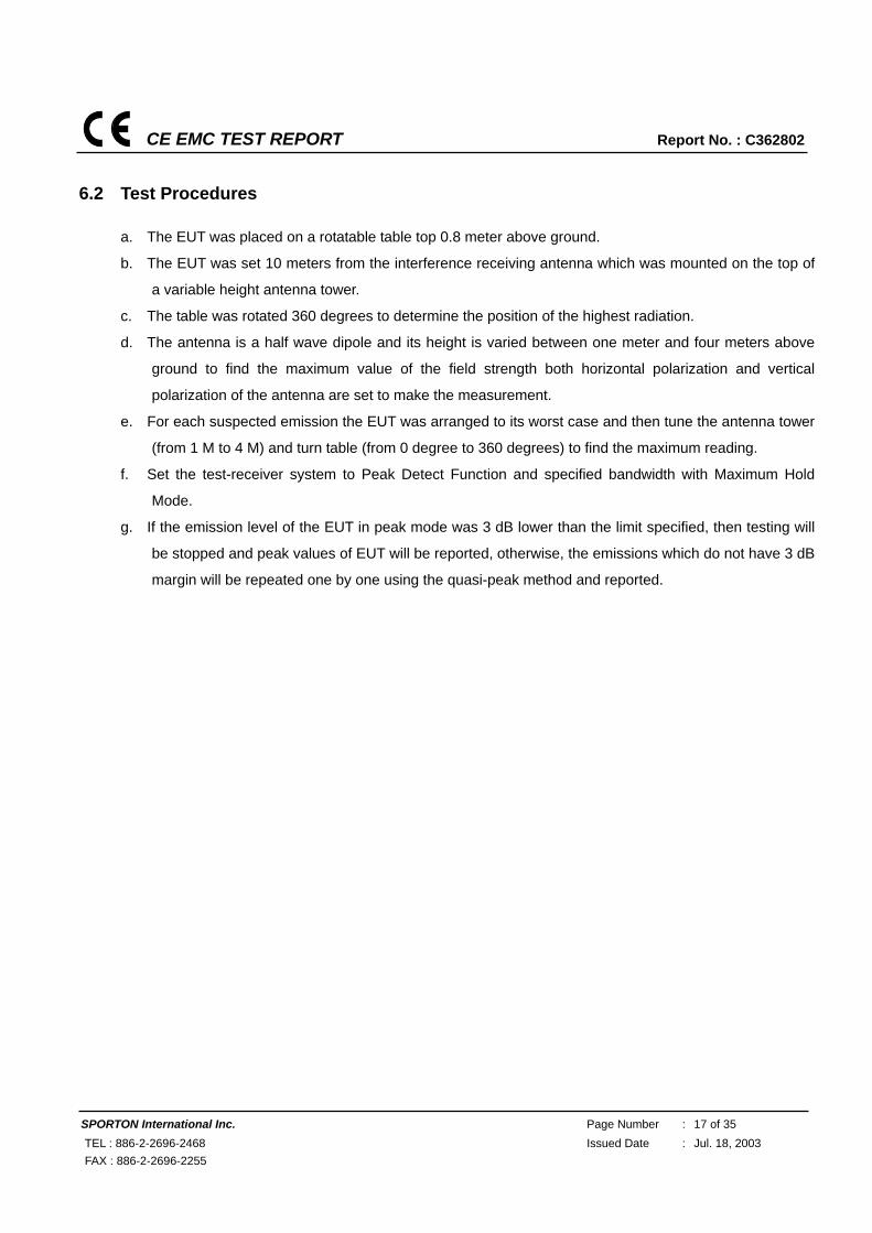
6.2 Test Procedures
a. The EUT was placed on a rotatable table top 0.8 meter above ground.
b. The EUT was set 10 meters from the interference receiving antenna which was mounted on the top of
a variable height antenna tower.
c. The table was rotated 360 degrees to determine the position of the highest radiation.
d. The antenna is a half wave dipole and its height is varied between one meter and four meters above
ground to find the maximum value of the field strength both horizontal polarization and vertical
polarization of the antenna are set to make the measurement.
e. For each suspected emission the EUT was arranged to its worst case and then tune the antenna tower
(from 1 M to 4 M) and turn table (from 0 degree to 360 degrees) to find the maximum reading.
f. Set the test-receiver system to Peak Detect Function and specified bandwidth with Maximum Hold
Mode.
g. If the emission level of the EUT in peak mode was 3 dB lower than the limit specified, then testing will
be stopped and peak values of EUT will be reported, otherwise, the emissions which do not have 3 dB
margin will be repeated one by one using the quasi-peak method and reported.
CE EMC TEST REPORT Report No. : C362802
SPORTON International Inc. Page Number : 18 of 35 TEL : 886-2-2696-2468 Issued Date : Jul. 18, 2003 FAX : 886-2-2696-2255
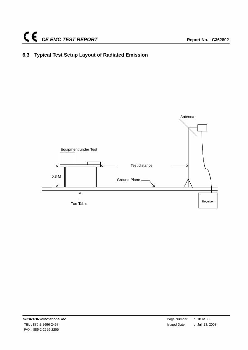
6.3 Typical Test Setup Layout of Radiated Emission
Antenna
0.8 M
Equipment under Test
Test distance
TurnTable
Ground Plane
Receiver
CE EMC TEST REPORT Report No. : C362802
SPORTON International Inc. Page Number : 19 of 35 TEL : 886-2-2696-2468 Issued Date : Jul. 18, 2003 FAX : 886-2-2696-2255
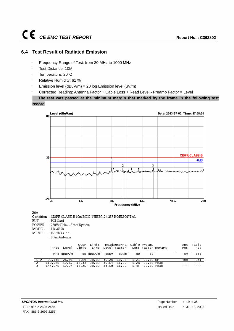
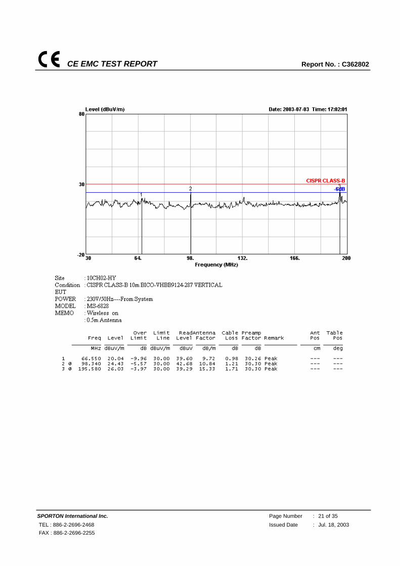
6.4 Test Result of Radiated Emission
Frequency Range of Test: from 30 MHz to 1000 MHz Test Distance: 10M Temperature: 20°C Relative Humidity: 61 % Emission level (dBuV/m) = 20 log Emission level (uV/m) Corrected Reading: Antenna Factor + Cable Loss + Read Level - Preamp Factor = Level ■ The test was passed at the minimum margin that marked by the frame in the following test record
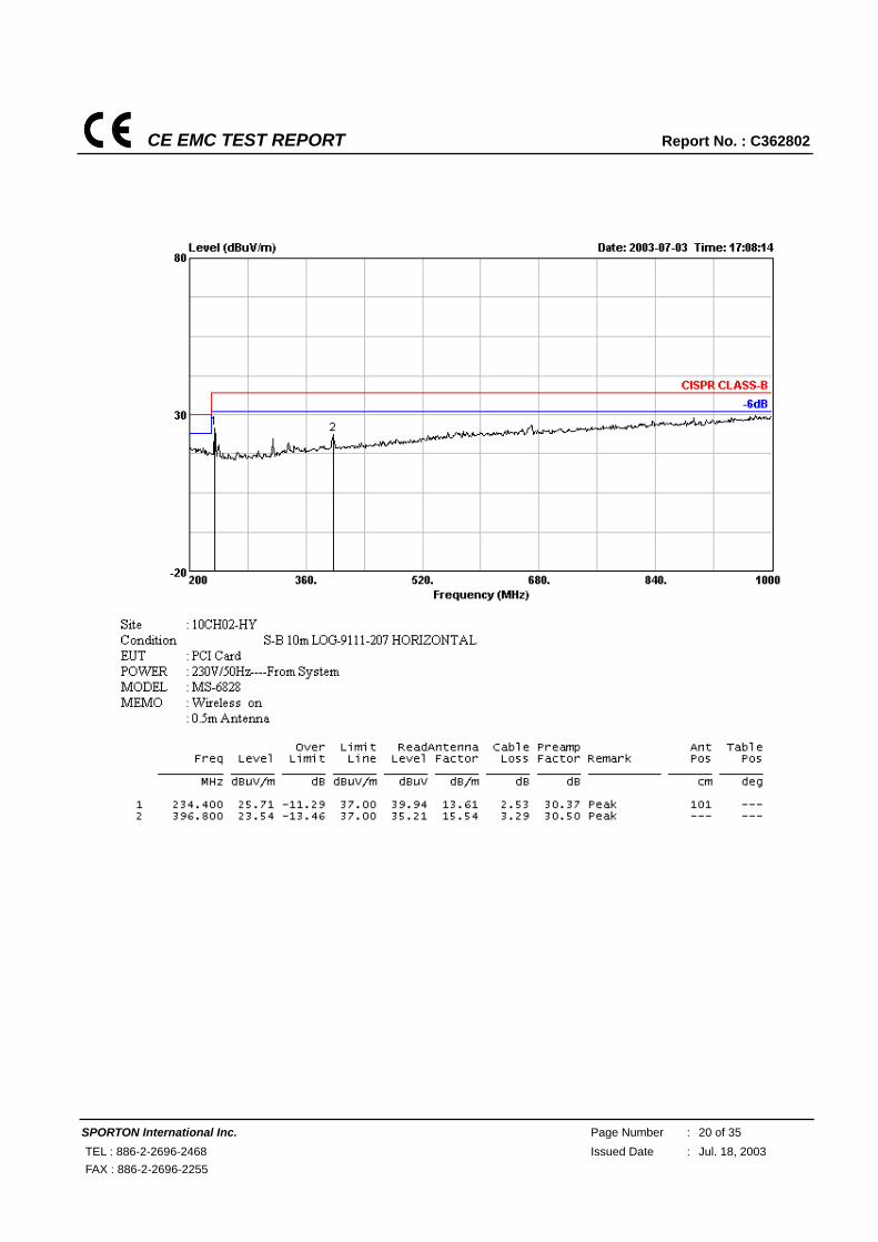
CE EMC TEST REPORT Report No. : C362802
SPORTON International Inc. Page Number : 20 of 35 TEL : 886-2-2696-2468 Issued Date : Jul. 18, 2003 FAX : 886-2-2696-2255
CE EMC TEST REPORT Report No. : C362802
SPORTON International Inc. Page Number : 21 of 35 TEL : 886-2-2696-2468 Issued Date : Jul. 18, 2003 FAX : 886-2-2696-2255

CE EMC TEST REPORT Report No. : C362802
SPORTON International Inc. Page Number : 22 of 35 TEL : 886-2-2696-2468 Issued Date : Jul. 18, 2003 FAX : 886-2-2696-2255
Test Engineer: Brian Lin
CE EMC TEST REPORT Report No. : C362802
SPORTON International Inc. Page Number : 23 of 35 TEL : 886-2-2696-2468 Issued Date : Jul. 18, 2003 FAX : 886-2-2696-2255
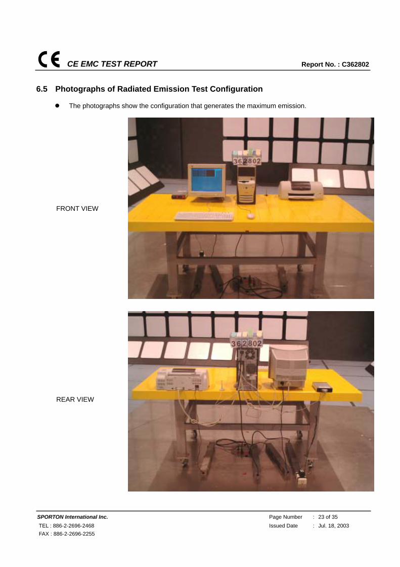
6.5 Photographs of Radiated Emission Test Configuration
The photographs show the configuration that generates the maximum emission.
FRONT VIEW
REAR VIEW
CE EMC TEST REPORT Report No. : C362802
SPORTON International Inc. Page Number : 24 of 35 TEL : 886-2-2696-2468 Issued Date : Jul. 18, 2003 FAX : 886-2-2696-2255
7. Electrostatic Discharge Immunity Test (ESD)
FINAL TEST RESULT : PASS Pass Performance Criteria : CT/CR Required performance criteria: TT/TR Basic Standard : EN 61000-4-2:1995/A1:1998 Product Standard : EN 301 489-17 Level : 2 for contact discharge Tested voltage : ±2 / ±4 KV for contact discharge Temperature : 24 °C Relative Humidity : 56 % Atmospheric Pressure : 98.2kPa Test Date : Jul. 04, 2003 Observation : Normal Remark : The EUT has no on slots, apertures, or insulating surfaces.
So, the air discharge test is not applicable
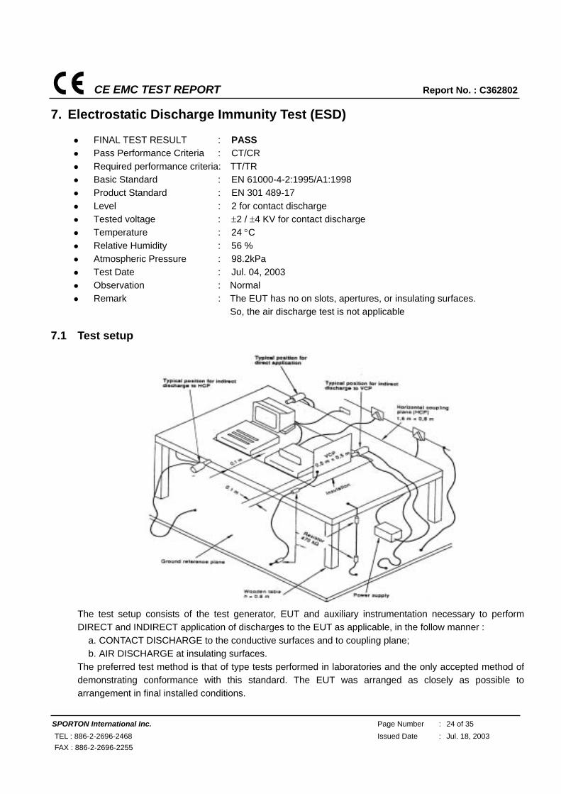
7.1 Test setup
The test setup consists of the test generator, EUT and auxiliary instrumentation necessary to perform DIRECT and INDIRECT application of discharges to the EUT as applicable, in the follow manner :
a. CONTACT DISCHARGE to the conductive surfaces and to coupling plane; b. AIR DISCHARGE at insulating surfaces.
The preferred test method is that of type tests performed in laboratories and the only accepted method of demonstrating conformance with this standard. The EUT was arranged as closely as possible to arrangement in final installed conditions.
CE EMC TEST REPORT Report No. : C362802
SPORTON International Inc. Page Number : 25 of 35 TEL : 886-2-2696-2468 Issued Date : Jul. 18, 2003 FAX : 886-2-2696-2255
7.2 Test Setup for Tests Performed in Laboratory
A ground reference plane was provided on the floor of the test site. It was a metallic sheet (copper or aluminum) of 0.25 mm, minimum thickness; other metallic may be used but they shall have at least 0.65 mm thickness. In the SPORTON EMC LAB., we provided 1 mm thickness aluminum ground reference plane or 1 mm thickness stainless steel ground reference plane. The minimum size of the ground reference plane is 1 m x 1 m, the exact size depending on the dimensions of the EUT. It was connected to the protective grounding system. The EUT was arranged and connected according to its functional requirements. A distance of 1m minimum was provided between the EUT and the wall of the lab. And any other metallic structure. In cases where this length exceeds the length necessary to apply the discharges to the selected points, the excess length shall, where possible, be placed non-inductively off the ground reference plane and shall not come closer than 0.2m to other conductive parts in the test setup. Where the EUT is installed on a metal table, the table was connected to the reference plane via a cable with a 470k ohm resister located at each end, to prevent a build-up of charge. The test setup was consist a wooden table, 0.8m high, standing on the ground reference plane. A HCP, 1.6 m x 0.8 m, was placed on the table. The EUT and cables was isolated from the HCP by an insulating support 0.5 mm thick. The VCP size, 0.5 m x 0.5 m.
CE EMC TEST REPORT Report No. : C362802
SPORTON International Inc. Page Number : 26 of 35 TEL : 886-2-2696-2468 Issued Date : Jul. 18, 2003 FAX : 886-2-2696-2255
7.3 ESD Test Procedure
a. In the case of air discharge testing the climatic conditions shall be within the following ranges:
- ambient temperature: 15℃ to 35℃;
- relative humidity : 30% to 60%;
- atmospheric pressure : 86 kPa (860 mbar) to 106 kPa (1060 mbar).
b. Test programs and software shall be chosen so as to exercise all normal modes of operation of the EUT.
The use of special exercising software is encouraged, but permitted only where it can be shown that the
EUT is being comprehensively exercised.
c. The test voltage shall be increased from the minimum to the selected test severity level, in order to
determine any threshold of failure. The final severity level should not exceed the product specification
value in order to avoid damage to the equipment.
d. The test shall be performed with single discharges. On preselected points at least ten single discharges
(in the most sensitive polarity) shall be applied.
e. For the time interval between successive single discharges an initial value of one second is
recommended. Longer intervals may be necessary to determine whether a system failure has occurred.
f. In the case of contact discharges, the tip of the discharge electrode shall touch the EUT before the
discharge switch is operated.
g. In the case of painted surface covering a conducting substrate, the following procedure shall be
adopted :
h. If the coating is not declared to be an insulating coating by the equipment manufacturer, then the pointed
tip of the generator shall penetrate the coating so as to make contact with the conducting substrate.
i. Coating declared as insulating by the manufacturer shall only be submitted to the air discharge.
j. The contact discharge test shall not be applied to such surfaces.
k. In the case of air discharges, the round discharge tip of the discharge electrode shall be approached as
fast as possible (without causing mechanical damage) to touch the EUT. After each discharge, the ESD
generator (discharge electrode) shall be removed from the EUT. The generator is then retriggered for a
new single discharge. This procedure shall be repeated until the discharges are completed. In the case
of an air discharge test, the discharge switch, which is used for contact discharge, shall be closed.
CE EMC TEST REPORT Report No. : C362802
SPORTON International Inc. Page Number : 27 of 35 TEL : 886-2-2696-2468 Issued Date : Jul. 18, 2003 FAX : 886-2-2696-2255
7.4 Test Severity Levels
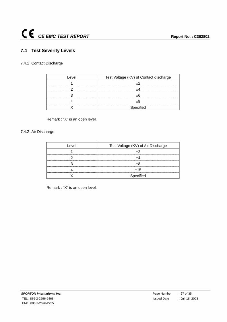
7.4.1 Contact Discharge
Level Test Voltage (KV) of Contact discharge
1 ±2 2 ±4 3 ±6 4 ±8 X Specified
Remark : “X” is an open level.
7.4.2 Air Discharge
Level Test Voltage (KV) of Air Discharge
1 ±2 2 ±4 3 ±8 4 ±15 X Specified
Remark : “X” is an open level.
CE EMC TEST REPORT Report No. : C362802
SPORTON International Inc. Page Number : 28 of 35 TEL : 886-2-2696-2468 Issued Date : Jul. 18, 2003 FAX : 886-2-2696-2255
7.5 Test Points
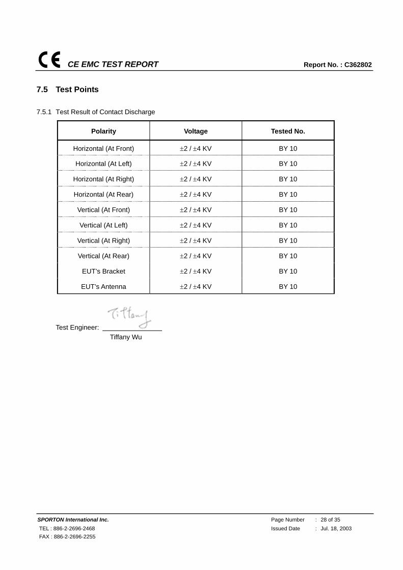
7.5.1 Test Result of Contact Discharge
Polarity Voltage Tested No.
Horizontal (At Front) ±2 / ±4 KV BY 10
Horizontal (At Left) ±2 / ±4 KV BY 10
Horizontal (At Right) ±2 / ±4 KV BY 10
Horizontal (At Rear) ±2 / ±4 KV BY 10
Vertical (At Front) ±2 / ±4 KV BY 10
Vertical (At Left) ±2 / ±4 KV BY 10
Vertical (At Right) ±2 / ±4 KV BY 10
Vertical (At Rear) ±2 / ±4 KV BY 10
EUT’s Bracket ±2 / ±4 KV BY 10
EUT’s Antenna ±2 / ±4 KV BY 10
Test Engineer: Tiffany Wu
CE EMC TEST REPORT Report No. : C362802
SPORTON International Inc. Page Number : 29 of 35 TEL : 886-2-2696-2468 Issued Date : Jul. 18, 2003 FAX : 886-2-2696-2255
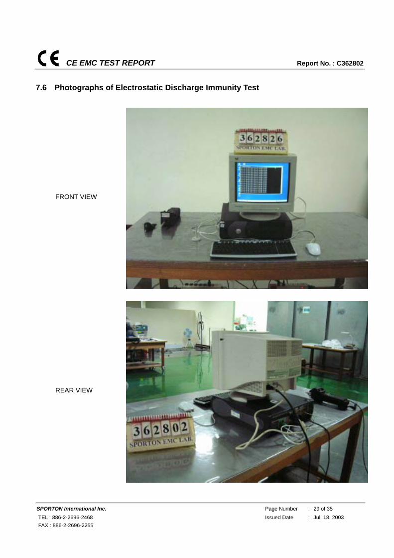
7.6 Photographs of Electrostatic Discharge Immunity Test
FRONT VIEW
REAR VIEW
CE EMC TEST REPORT Report No. : C362802
SPORTON International Inc. Page Number : 30 of 35 TEL : 886-2-2696-2468 Issued Date : Jul. 18, 2003 FAX : 886-2-2696-2255
8. Radio Frequency Electromagnetic Field Immunity Test (RS)
FINAL TEST RESULT : PASS
Pass Performance Criteria : CT/CR
Required performance criteria: CT/CR
Basic Standard : EN 61000-4-3:1996/A1:1998 Product Standard : EN 301 489-17
Level : 2
Frequency Range : 80-1000 MHz, 1400~2000 MHz
Field Strength : 3 V/m (Modulated 80% AM)
Temperature : 23 °C
Relative Humidity : 54 % Atmospheric Pressure : 98.2kPa Test Date : Jul. 04, 2003
Observation : Normal
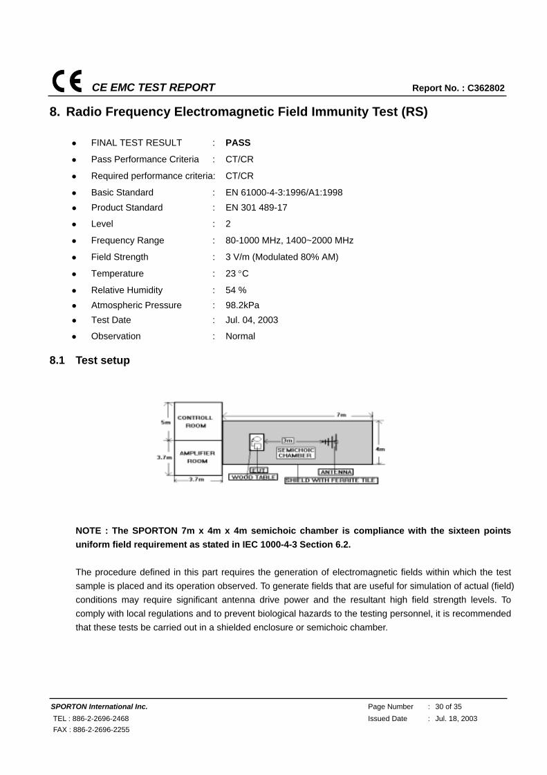
8.1 Test setup
NOTE : The SPORTON 7m x 4m x 4m semichoic chamber is compliance with the sixteen points uniform field requirement as stated in IEC 1000-4-3 Section 6.2. The procedure defined in this part requires the generation of electromagnetic fields within which the test sample is placed and its operation observed. To generate fields that are useful for simulation of actual (field) conditions may require significant antenna drive power and the resultant high field strength levels. To comply with local regulations and to prevent biological hazards to the testing personnel, it is recommended that these tests be carried out in a shielded enclosure or semichoic chamber.
CE EMC TEST REPORT Report No. : C362802
SPORTON International Inc. Page Number : 31 of 35 TEL : 886-2-2696-2468 Issued Date : Jul. 18, 2003 FAX : 886-2-2696-2255
8.2 Test Procedure
a. The equipment to be tested is placed in the center of the enclosure on a wooden table. The equipment is then connected to power and signal leads according to pertinent installation instructions.
b. The bilog antenna which is enabling the complete frequency range of 80-1000 MHz, 1400-2000 MHz is placed 3m away from the equipment. The required field strength is determined by placing the field strength meter(s) on top of or directly alongside the equipment under test and monitoring the field strength meter via a remote field strength indicator outside the enclosure while adjusting the continuous-wave to the applicable antennae.
c. The test is normally performed with the antenna facing the most sensitive side of the EUT. The polarization of the field generated by the biconical antenna necessitates testing each position twice, once with the antenna positioned vertically and again with the antenna positioned horizontally. The circular polarization of the field from the log-spiral antenna makes a change of position of the antenna unnecessary.
d. At each of the above conditions, the frequency range is swept 80-1000 MHz, 1400-2000 MHz, pausing to adjust the R.F. signal level or to switch oscillators and antenna. The rate of sweep is in the order of 1.5*10-3 decades/s. The sensitive frequencies or frequencies of dominant interest may be discretely analyzed.
8.3 Test Severity Levels
Frequency Band: 80-1000 MHz, 1400-2000 MHz
Level Test field strength (V/m)
1 1
2 3
3 10
X Specified
Remark : “X” is an open class.
Test Engineer: Tiffany Wu
CE EMC TEST REPORT Report No. : C362802
SPORTON International Inc. Page Number : 32 of 35 TEL : 886-2-2696-2468 Issued Date : Jul. 18, 2003 FAX : 886-2-2696-2255
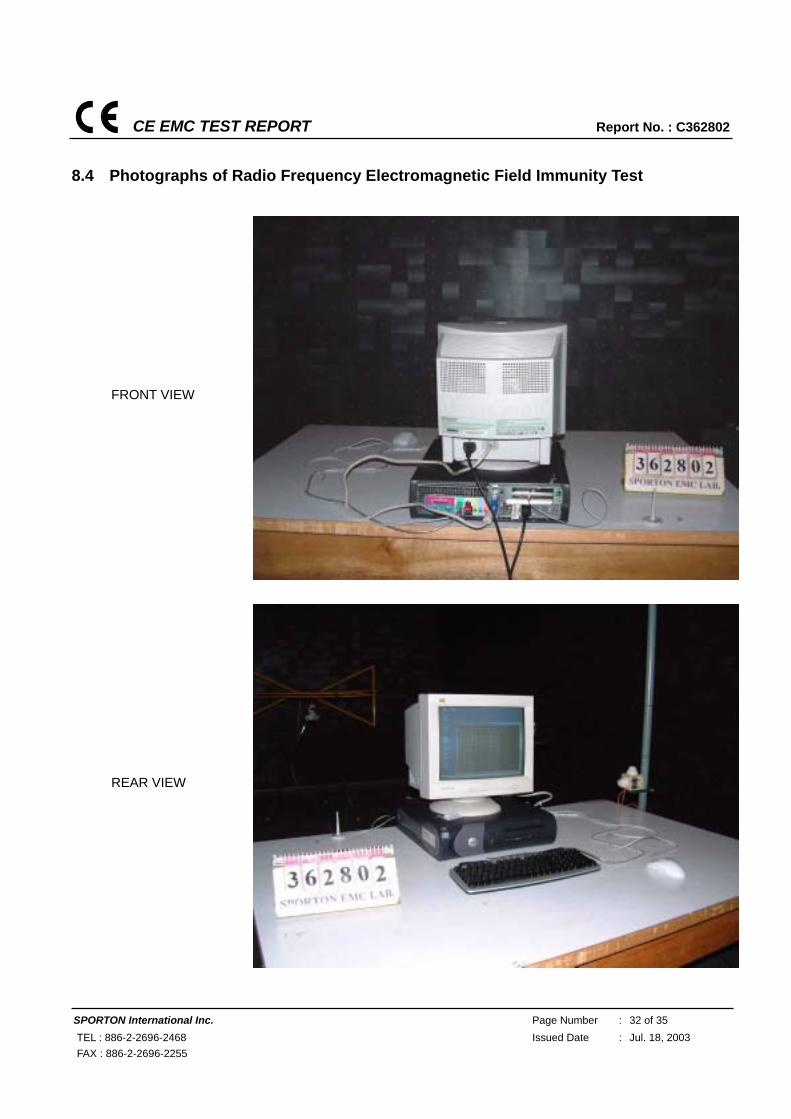
8.4 Photographs of Radio Frequency Electromagnetic Field Immunity Test
FRONT VIEW
REAR VIEW
CE EMC TEST REPORT Report No. : C362802
SPORTON International Inc. Page Number : 33 of 35 TEL : 886-2-2696-2468 Issued Date : Jul. 18, 2003 FAX : 886-2-2696-2255
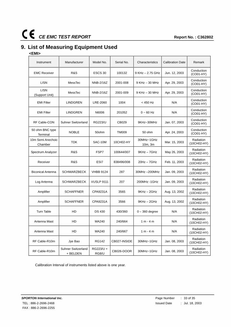
9. List of Measuring Equipment Used <EMI>
Instrument Manufacturer Model No. Serial No. Characteristics Calibration Date Remark
EMC Receiver R&S ESCS 30 100132 9 KHz – 2.75 GHz Jun. 12, 2003 Conduction (CO01-HY)
LISN MessTec NNB-2/16Z 2001-008 9 KHz – 30 MHz Apr. 29, 2003 Conduction (CO01-HY)
LISN (Support Unit)
MessTec NNB-2/16Z 2001-009 9 KHz – 30 MHz Apr. 29, 2003 Conduction (CO01-HY)
EMI Filter LINDGREN LRE-2060 1004 < 450 Hz N/A Conduction (CO01-HY)
EMI Filter LINDGREN N6006 201052 0 ~ 60 Hz N/A Conduction (CO01-HY)
RF Cable-CON Suhner Switzerland RG223/U CB029 9KHz~30MHz Jan. 07, 2003 Conduction (CO01-HY)
50 ohm BNC type Terminal
NOBLE 50ohm TM009 50 ohm Apr. 24, 2003 Conduction (CO01-HY)
10m Semi Anechoic Chamber
TDK SAC-10M 10CH02-HY30MHz~1GHz
10m, 3m Mar. 15, 2003
Radiation (10CH02-HY)
Spectrum Analyzer R&S FSP7 100644/007 9KHz – 7GHz May 26, 2003 Radiation
(10CH02-HY)
Receiver R&S ESI7 838496/008 20Hz – 7GHz Feb. 11, 2003 Radiation
(10CH02-HY)
Biconical Antenna SCHWARZBECK VHBB 9124 287 30MHz –200MHz Jan. 09, 2003 Radiation
(10CH02-HY)
Log Antenna SCHWARZBECK VUSLP 9111 207 200MHz -1GHz Jan. 09, 2003 Radiation
(10CH02-HY)
Amplifier SCHAFFNER CPA9231A 3565 9KHz – 2GHz Aug. 13, 2002 Radiation
(10CH02-HY)
Amplifier SCHAFFNER CPA9231A 3566 9KHz – 2GHz Aug. 13, 2002 Radiation
(10CH02-HY)
Turn Table HD DS 430 430/360 0 ∼ 360 degree N/A Radiation
(10CH02-HY)
Antenna Mast HD MA240 240/664 1 m - 4 m N/A Radiation
(10CH02-HY)
Antenna Mast HD MA240 240/667 1 m - 4 m N/A Radiation
(10CH02-HY)
RF Cable-R10m Jye Bao RG142 CB027-INSIDE 30MHz~1GHz Jan. 08, 2003 Radiation
(10CH02-HY)
RF Cable-R10m Suhner Switzerland
+ BELDEN RG223/U +
RG8/U CB026-DOOR 30MHz~1GHz Jan. 08, 2003
Radiation (10CH02-HY)
※ Calibration Interval of instruments listed above is one year.
CE EMC TEST REPORT Report No. : C362802
SPORTON International Inc. Page Number : 34 of 35 TEL : 886-2-2696-2468 Issued Date : Jul. 18, 2003 FAX : 886-2-2696-2255
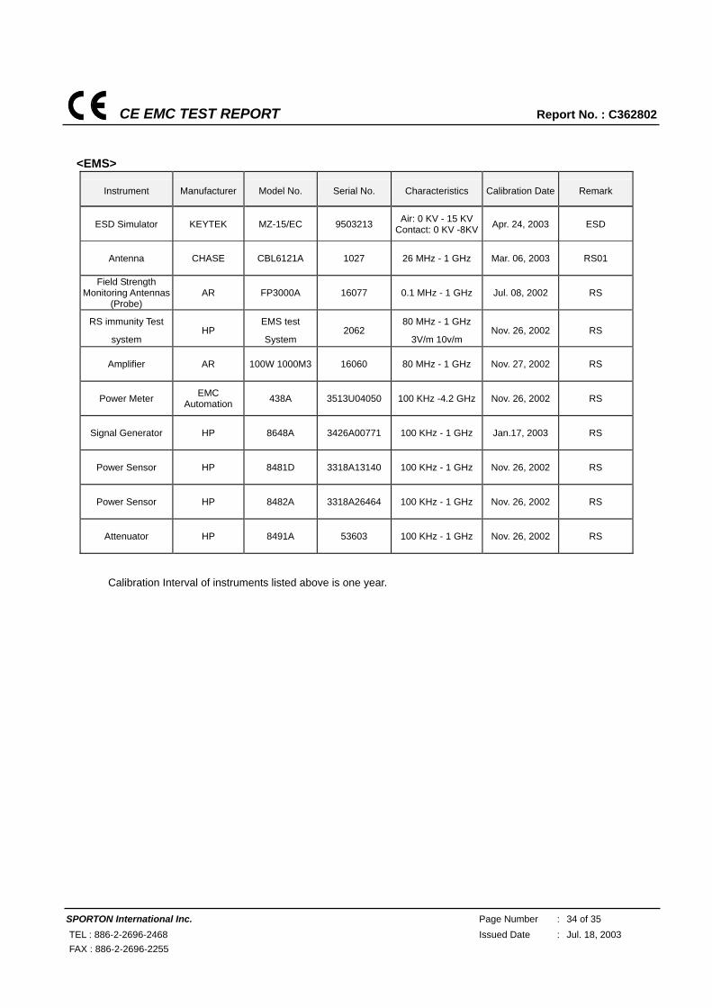
<EMS>
Instrument Manufacturer Model No. Serial No. Characteristics Calibration Date Remark
ESD Simulator KEYTEK MZ-15/EC 9503213 Air: 0 KV - 15 KVContact: 0 KV -8KV Apr. 24, 2003 ESD
Antenna CHASE CBL6121A 1027 26 MHz - 1 GHz Mar. 06, 2003 RS01
Field Strength Monitoring Antennas
(Probe) AR FP3000A 16077 0.1 MHz - 1 GHz Jul. 08, 2002 RS
RS immunity Test
system HP
EMS test
System 2062
80 MHz - 1 GHz
3V/m 10v/m Nov. 26, 2002 RS
Amplifier AR 100W 1000M3 16060 80 MHz - 1 GHz Nov. 27, 2002 RS
Power Meter EMC Automation 438A 3513U04050 100 KHz -4.2 GHz Nov. 26, 2002 RS
Signal Generator HP 8648A 3426A00771 100 KHz - 1 GHz Jan.17, 2003 RS
Power Sensor HP 8481D 3318A13140 100 KHz - 1 GHz Nov. 26, 2002 RS
Power Sensor HP 8482A 3318A26464 100 KHz - 1 GHz Nov. 26, 2002 RS
Attenuator HP 8491A 53603 100 KHz - 1 GHz Nov. 26, 2002 RS
※ Calibration Interval of instruments listed above is one year.
CE EMC TEST REPORT Report No. : C362802
SPORTON International Inc. Page Number : 35 of 35 TEL : 886-2-2696-2468 Issued Date : Jul. 18, 2003 FAX : 886-2-2696-2255
10. Declaration of Conformity and the CE Mark There are three possible procedures pertaining to the declaration of conformity:
10.1 Conformity Testing and Declaration of Conformity by the Manufacturer or His Authorized Representative Established within the Community or by an Importer.
- Article 10 (1) of the EMC Directive, - § 3 (1) no. 2a of the EMC Act.
10.2 Declaration of Conformity Issued by the Manufacturer or His Authorized Representative Established within the Community or by an Importer Following Testing of the Product and Issued of an EC certificate of conformity by a competent body.
- Article 10 (2) of the EMC Directive, - § 3 (1) no. 2b of the EMC Act.
10.3 Declaration of Conformity Issued by the Manufacturer or His Authorized Representative Established within the Community or by an Importer Following Testing and Certification of the Product by a Notified Body.
- Article 10 (5) of the EMC Directive, - § 3 (1) no. 2b of the EMC Act (radio transmitting installations).
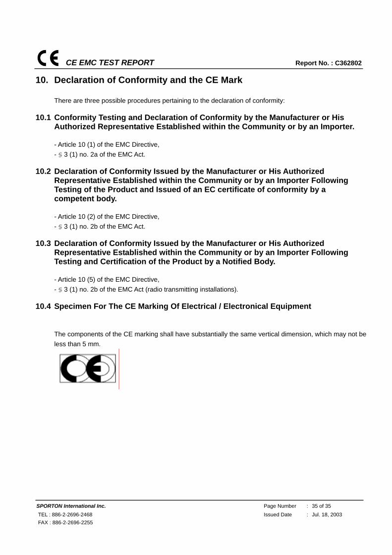
10.4 Specimen For The CE Marking Of Electrical / Electronical Equipment
The components of the CE marking shall have substantially the same vertical dimension, which may not be less than 5 mm.