Embed Size (px)
Citation preview
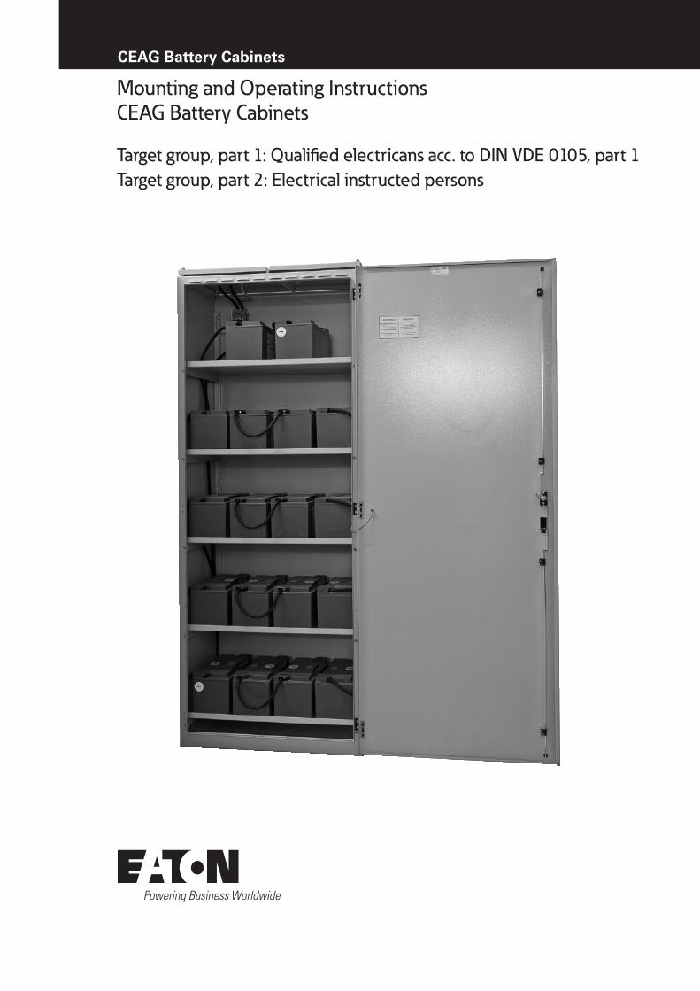
CEAG Battery Cabinets
Mounting and Operating Instructions CEAG Battery Cabinets
Target group, part 1: Qualified electricans acc. to DIN VDE 0105, part 1Target group, part 2: Electrical instructed persons
2 Mounting and Operating Instructions CEAG Battery Cabinets 40071860035 (P) July 2016 www.ceag.de
Index
Index
1 General Information
1.1 Description of Symbols . . . . . . . . . . 4
1.2 Information regarding these instructions . . . . 4
1.3 Further Applicable Documents . . . . . . . . 4
1.4 Liability and Guarantee . . . . . . . . . . . 4
1.5 Copyright Protection . . . . . . . . . . . . 4
1.6 Spare Parts . . . . . . . . . . . . . . . 4
1.7 Recycling . . . . . . . . . . . . . . . . 4
2 Safety
2.1 Intended Use . . . . . . . . . . . . . . 5
2.2 Contents of Operating Instructions . . . . . . 5
2.3 Changes and Modifications to the Battery . . . 5
2.4 Responsibility of the Operator . . . . . . . . 5
2.5 Personnel Requirements . . . . . . . . . . 5
2.6 Operational Safety . . . . . . . . . . . . 5
2.7 Personal Protective Equipment . . . . . . . 5
2.8 Danger caused by the Battery . . . . . . . . 5
3 Technical Data
3.1 Standard-Battery Cabinets . . . . . . . . . 6
3.1.1 With battery set 23.3 Ah . . . . . . . . . . 6
3.1.2 With battery set 32 Ah . . . . . . . . . . 7
3.1.3 With battery set 39.8 Ah . . . . . . . . . . 8
3.1.4 With battery set 50.4 Ah . . . . . . . . . . 9
3.1.5 With battery set 53.7 Ah . . . . . . . . . .10
3.1.6 With battery set 66.2 Ah . . . . . . . . . . 11
3.1.7 With battery set 85.7 Ah . . . . . . . . . .12
3.1.8 With battery set 89.4 Ah . . . . . . . . . .13
3.1.9 With battery set 106 Ah . . . . . . . . . .14
3.1.10 With battery set 118 Ah . . . . . . . . . .15
3.1.11 With battery set 143.1 Ah . . . . . . . . .16
3.1.12 With battery set 155.6 Ah . . . . . . . . .17
3.1.13 With battery set 178.8 Ah . . . . . . . . .18
3.1.14 With battery set 195.4 Ah . . . . . . . . .19
3.1.15 With battery set 245 Ah . . . . . . . . . .20
3.1.16 With battery set 268.2 Ah . . . . . . . . .21
3.1.17 With battery set 308 Ah . . . . . . . . . .22
3.1.18 With battery set 357.6 Ah . . . . . . . . .23
3.2 Compact-Battery Cabinets 2C3 . . . . . . .24
3.2.1 With battery set 5.5 Ah . . . . . . . . . .24
3.2.2 With battery set 8.5 Ah / 11.6 Ah . . . . . . .25
3.2.3 With battery set 14 Ah . . . . . . . . . . .26
3.3 Compact-Battery Cabinets 10C3, 18C3 . . . .27
3.3.1 With battery set 5.5 Ah . . . . . . . . . .27
3.3.2 With battery set 8.5 Ah / 11.6 Ah . . . . . . .28
3.3.3 With battery set 14 Ah . . . . . . . . . . .29
3.3.4 With battery set 23.3 Ah . . . . . . . . . .30
3.4 Compact-Battery Cabinets 10C . . . . . . .31
3.4.1 With battery set 23.3 Ah . . . . . . . . . .31
3.4.2 With battery set 32 Ah . . . . . . . . . . .32
3.4.3 With battery set 39.8 Ah . . . . . . . . . .33
3.4.4 With battery set 50.4 Ah . . . . . . . . . .34
3.4.5 With battery set 53.7 Ah . . . . . . . . . .35
3.5 Compact-Battery Cabinets 10C6, 18C6, 26C6 . .36
3.5.1 With battery set 23.3 Ah . . . . . . . . . .36
3.5.2 With battery set 32.0 Ah . . . . . . . . . .37
3.5.3 With battery set 39.8 Ah . . . . . . . . . .38
3.5.4 With battery set 50.4 Ah . . . . . . . . . .39
3.5.5 With battery set 53.7 Ah . . . . . . . . . .40
3.5.6 With battery set 66.2 Ah . . . . . . . . . .41
3.5.7 With battery set 85.7 Ah . . . . . . . . . .42
3.5.8 With battery set 89.4 Ah . . . . . . . . . .43
4 Circuit Diagram
4.1 Wiring 5.5 Ah to 89.4 Ah . . . . . . . . . .44
4.2 Wiring 118 Ah . . . . . . . . . . . . . .44
4.3 Wiring 106, 143.1, 155.6, 178.8 Ah . . . . . .45
4.4 Wiring 195.4, 245, 268.2 Ah . . . . . . . . .46
4.5 Wiring 308, 357.6 Ah . . . . . . . . . . .47
5 Transport, Packaging and Storage
5.1 Safety Notes . . . . . . . . . . . . . . .48
5.2 Carriage by Land of Closed Lead Acid Batteries .48
5.3 Carriage by Sea of Closed Lead Acid Batteries .48
5.4 Carriage by Air of Closed Lead Acid Batteries . .48
5.5 Abbreviations . . . . . . . . . . . . . .48
5.6 Transport Inspection . . . . . . . . . . . .48
5.7 Packaging . . . . . . . . . . . . . . . .48
5.8 Requirements and Preconditions . . . . . . .48
5.9 Storage Conditions . . . . . . . . . . . .48
5.10 Storage . . . . . . . . . . . . . . . . .49
5.11 Time of Storage . . . . . . . . . . . . .49
5.12 Measures during Storage . . . . . . . . . .49
3Mounting and Operating Instructions CEAG Battery Cabinets 40071860035 (P) July 2016 www.ceag.de
Index
6 Installation
6.1 Safety Notes . . . . . . . . . . . . . . .50
6.2 Battery Rooms, Ventilation and
General Requirements . . . . . . . . . . .50
6.2.1 Temperature . . . . . . . . . . . . . . .50
6.2.2 Room Dimensions and Surface Conditions . . .51
6.2.3 Ventilation . . . . . . . . . . . . . . . .51
6.2.3.1 Ventilation Requirements . . . . . . . . . .52
6.2.3.2 Close Vicinity of the Battery . . . . . . . . .52
6.2.4 Electrial Requirements (Protection, Insulation,
Resistance, etc.) . . . . . . . . . . . . .52
6.2.5 Installation . . . . . . . . . . . . . . .52
6.3 Preparations . . . . . . . . . . . . . . .53
6.4 Mounting . . . . . . . . . . . . . . . .53
6.5 Parallel Arrangements . . . . . . . . . . .53
6.6 Mounting Positions for AGM Cells and
Monoblocs . . . . . . . . . . . . . . .53
7 Commissioning . . . . . . . . . . . . .54
8 Operating
8.1 Safety Notes . . . . . . . . . . . . . . .54
9 Maintenance
9.1 Safety Notes . . . . . . . . . . . . . . .54
9.2 Maintenance . . . . . . . . . . . . . .54
9.2.1 General Items and Checks (acc. to Operating
Instructions / Appendix) . . . . . . . . . .54
9.2.2 Cleaning of Batteries . . . . . . . . . . .54
10 Failures
10.1 Failure Performances . . . . . . . . . . .55
11 Spare Parts
11.1 Order of Spare Parts . . . . . . . . . . . .55
Appendix . . . . . . . . . . . . . . . .56
4 Mounting and Operating Instructions CEAG Battery Cabinets 40071860035 (P) July 2016 www.ceag.de
1 General Information
Important Notes
1 General Information
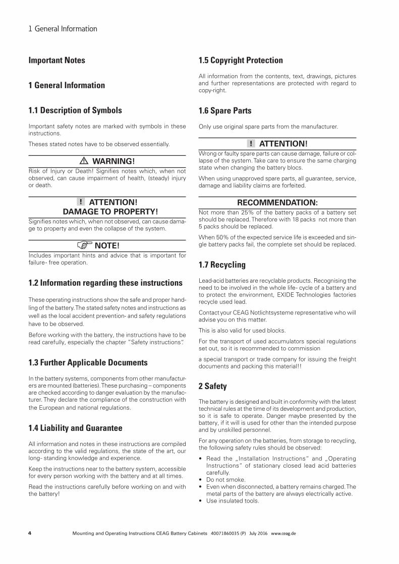
1.1 Description of Symbols
Important safety notes are marked with symbols in these instructions.
Theses stated notes have to be observed essentially.
WARNING! Risk of Injury or Death! Signifies notes which, when not observed, can cause impairment of health, (steady) injury or death.
ATTENTION! DAMAGE TO PROPERTY!
Signifies notes which, when not observed, can cause dama-ge to property and even the collapse of the system.
NOTE!Includes important hints and advice that is important for failure - free operation.
1.2 Information regarding these instructions
These operating instructions show the safe and proper hand-ling of the battery. The stated safety notes and instructions as well as the local accident prevention- and safety regulations have to be observed.
Before working with the battery, the instructions have to be read carefully, especially the chapter ”Safety instructions“.
1.3 Further Applicable Documents
In the battery systems, components from other manufactur-ers are mounted (batteries). These purchasing – components are checked according to danger evaluation by the manufac-turer. They declare the compliance of the construction with the European and national regulations.
1.4 Liability and Guarantee
All information and notes in these instructions are compiled according to the valid regulations, the state of the art, our long - standing knowledge and experience.
Keep the instructions near to the battery system, accessible for every person working with the battery and at all times.
Read the instructions carefully before working on and with the battery!
1.5 Copyright Protection
All information from the contents, text, drawings, pictures and further representations are protected with regard to copy-right.
1.6 Spare Parts
Only use original spare parts from the manufacturer.
ATTENTION!Wrong or faulty spare parts can cause damage, failure or col-lapse of the system. Take care to ensure the same charging state when changing the battery blocs.
When using unapproved spare parts, all guarantee, service, damage and liability claims are forfeited.
RECOMMENDATION:Not more than 25% of the battery packs of a battery set should be replaced. Therefore with 18 packs not more than 5 packs should be replaced.
When 50% of the expected service life is exceeded and sin-gle battery packs fail, the complete set should be replaced.
1.7 Recycling
Lead-acid batteries are recyclable products. Recognising the need to be involved in the whole life - cycle of a battery and to protect the environment, EXIDE Technologies factories recycle used lead.
Contact your CEAG Notlichtsysteme representative who will advise you on this matter.
This is also valid for used blocks.
For the transport of used accumulators special regulations set out, so it is recommended to commission
a special transport or trade company for issuing the freight documents and packing this material!!
2 Safety
The battery is designed and built in conformity with the latest technical rules at the time of its development and production, so it is safe to operate. Danger maybe presented by the battery, if it will is used for other than the intended purpose and by unskilled personnel.
For any operation on the batteries, from storage to recycling, the following safety rules should be observed:
• Read the „Installation Instructions“ and „Operating Instructions“ of stationary closed lead acid batteries carefully.
• Do not smoke.• Even when disconnected, a battery remains charged. The
metal parts of the battery are always electrically active. • Use insulated tools.
5Mounting and Operating Instructions CEAG Battery Cabinets 40071860035 (P) July 2016 www.ceag.de
2 Safety
• Never place tools on the batteries (metal tools are parti-cularly dangerous).
• Check the starting torque of the block connector when the bolted assembly is insecure (see Appendix).
• Never lift the cells / monoblocs at the terminals.• Avoid shocks.• Never use synthetic cloth or sponge to clean the cells
/ monoblocs. Use water (wet cloth) without additives.• Discard metallic items like watches or jewelry.
2.1 Intended Use
Battery cabinets are exclusively for power supply to an emergency lighting system.
The operating safety can only be guaranteed by intended use of the battery cabinet / battery racks.
ATTENTION!Every use beyond or different than the intended purpose is prohibited, and therefore not in accordance with regulations! Battery cabinets are exclusively for emergency – power supply.
2.2 Contents of Operating Instructions
Every person, ordered to work with the battery, has to read the instructions carefully to understand them before work begins. This takes also place when the person has already worked with a similar kind of battery or was instructed by the manufacturer.
2.3 Changes and Modifications to the Battery
To avoid danger and to assure optimum performance, chan-ges and modifications to the battery are not allowed, except when the manufacturer has approved them.
2.4 Responsibility of the Operator
Keep the instructions near to the battery system, accessible for every person working with the battery and at all times.
Battery must be in a proper and safe condition when using it. Battery has to be checked for intactness before using it.
Adhere to the information of the instructions completely!
2.5 Personnel Requirements
Only authorised and skilled personnel are allowed to work on and with the battery. The personnel must have received instructions regarding the existing danger.
Skilled personnel refers to those with expert training, with knowledge and experience as well as knowledge of the re-levant regulations. He should be able to evaluate his work and recognize the presence of danger.
Personnel without the necessary knowledge must be trained.
2.6 Operational Safety
Observing the stated safety instructions and regulations can avoid damage to property and people when working with the battery.
2.7 Personal Protective Equipment
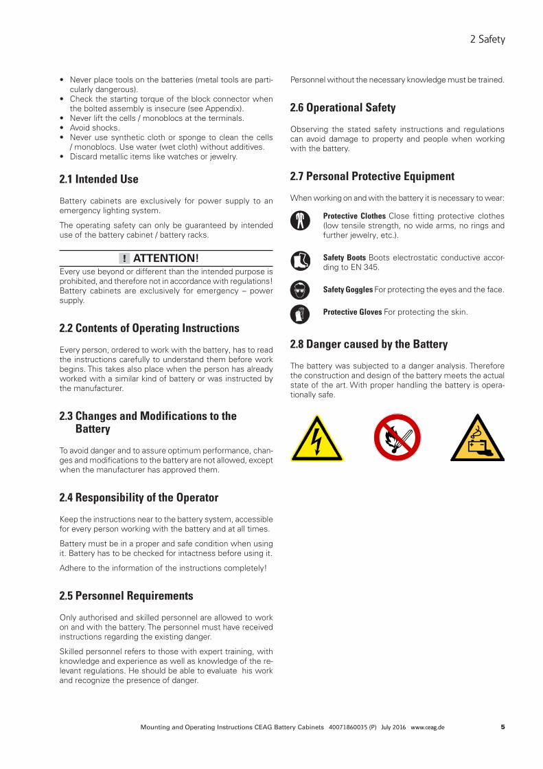
When working on and with the battery it is necessary to wear:
Protective Clothes Close fitting protective clothes (low tensile strength, no wide arms, no rings and further jewelry, etc.).
Safety Boots Boots electrostatic conductive accor-ding to EN 345.
Safety Goggles For protecting the eyes and the face.
Protective Gloves For protecting the skin.
2.8 Danger caused by the Battery
The battery was subjected to a danger analysis. Therefore the construction and design of the battery meets the actual state of the art. With proper handling the battery is opera-tionally safe.
6 Mounting and Operating Instructions CEAG Battery Cabinets 40071860035 (P) July 2016 www.ceag.de
3 Technical Data / Battery Installation
3 Technical Data / Battery Installation
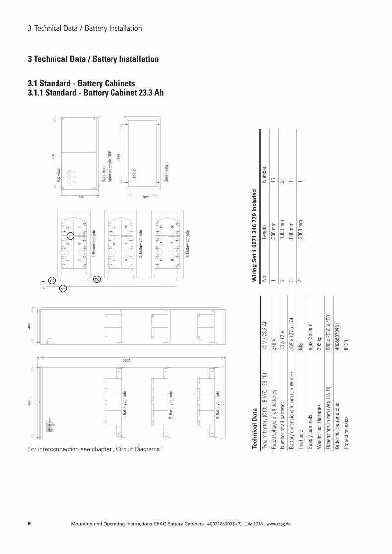
3.1 Standard - Battery Cabinets 3.1.1 Standard - Battery Cabinet 23.3 Ah
For interconnection see chapter „Circuit Diagrams“
1
23
4
Tech
nic
al D
ata
Type
of b
atte
ry (C
10; 1
.8 V
/Z; +
20 °
C)12
V /
23.3
Ah
Rate
d vo
ltage
of a
ll ba
tterie
s21
6 V
Num
ber o
f all
batte
ries
18 á
12
V
Batte
ry d
imen
sion
s in
mm
(L x
W x
H)
168
x 12
7 x
174
final
pol
eM
6
Supp
ly te
rmin
als
max
. 35
mm
²
Wei
ght i
ncl.
Batte
ries
295
kg
Dim
ensi
ons
in m
m (W
x H
x D
)80
0 x
2050
x 4
00
Orde
r no.
bat
terie
blo
c40
0660
7046
1
Prot
ectio
n ca
lss
IP 2
0
Wir
ing
Set
4 0
071
346
779
incl
ud
ed
No.
Leng
thN
umbe
r
130
0 m
m15
210
00 m
m2
380
0 m
m1
420
00 m
m1
1. B
atte
ry c
onso
le
1. B
atte
ry c
onso
le
2. B
atte
ry c
onso
le
2. B
atte
ry c
onso
le
3. B
atte
ry c
onso
le
3. B
atte
ry c
onso
le
Righ
t hin
ge
Aper
ture
ang
le 1
80°
Base
fixi
ng
Top
view
7Mounting and Operating Instructions CEAG Battery Cabinets 40071860035 (P) July 2016 www.ceag.de
3 Technical Data / Battery Installation
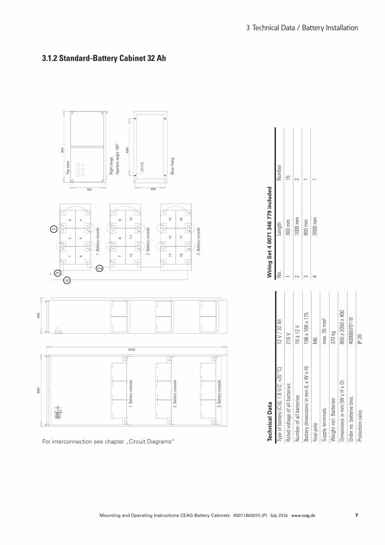
3.1.2 Standard-Battery Cabinet 32 Ah
For interconnection see chapter „Circuit Diagrams“
1
2
3
4
3 Technical Data / Battery Installation
Tech
nic
al D
ata
Type
of b
atte
ry (C
10; 1
.8 V
/Z; +
20 °
C)12
V /
32 A
h
Rate
d vo
ltage
of a
ll ba
tterie
s21
6 V
Num
ber o
f all
batte
ries
18 á
12
V
Batte
ry d
imen
sion
s in
mm
(L x
W x
H)
198
x 16
8 x
175
final
pol
eM
6
Supp
ly te
rmin
als
max
. 35
mm
²
Wei
ght i
ncl.
Batte
ries
370
kg
Dim
ensi
ons
in m
m (W
x H
x D
)80
0 x
2050
x 4
00
Orde
r no.
bat
terie
blo
c40
0660
7011
6
Prot
ectio
n ca
lss
IP 2
0
Wir
ing
Set
4 0
071
346
779
incl
ud
ed
No.
Leng
thN
umbe
r
130
0 m
m15
210
00 m
m2
380
0 m
m1
420
00 m
m1
1. B
atte
ry c
onso
le
1. B
atte
ry c
onso
le
2. B
atte
ry c
onso
le
2. B
atte
ry c
onso
le
3. B
atte
ry c
onso
le
3. B
atte
ry c
onso
le
Righ
t hin
ge
Aper
ture
ang
le 1
80°
Base
fixi
ng
Top
view
8 Mounting and Operating Instructions CEAG Battery Cabinets 40071860035 (P) July 2016 www.ceag.de
3 Technical Data / Battery Installation
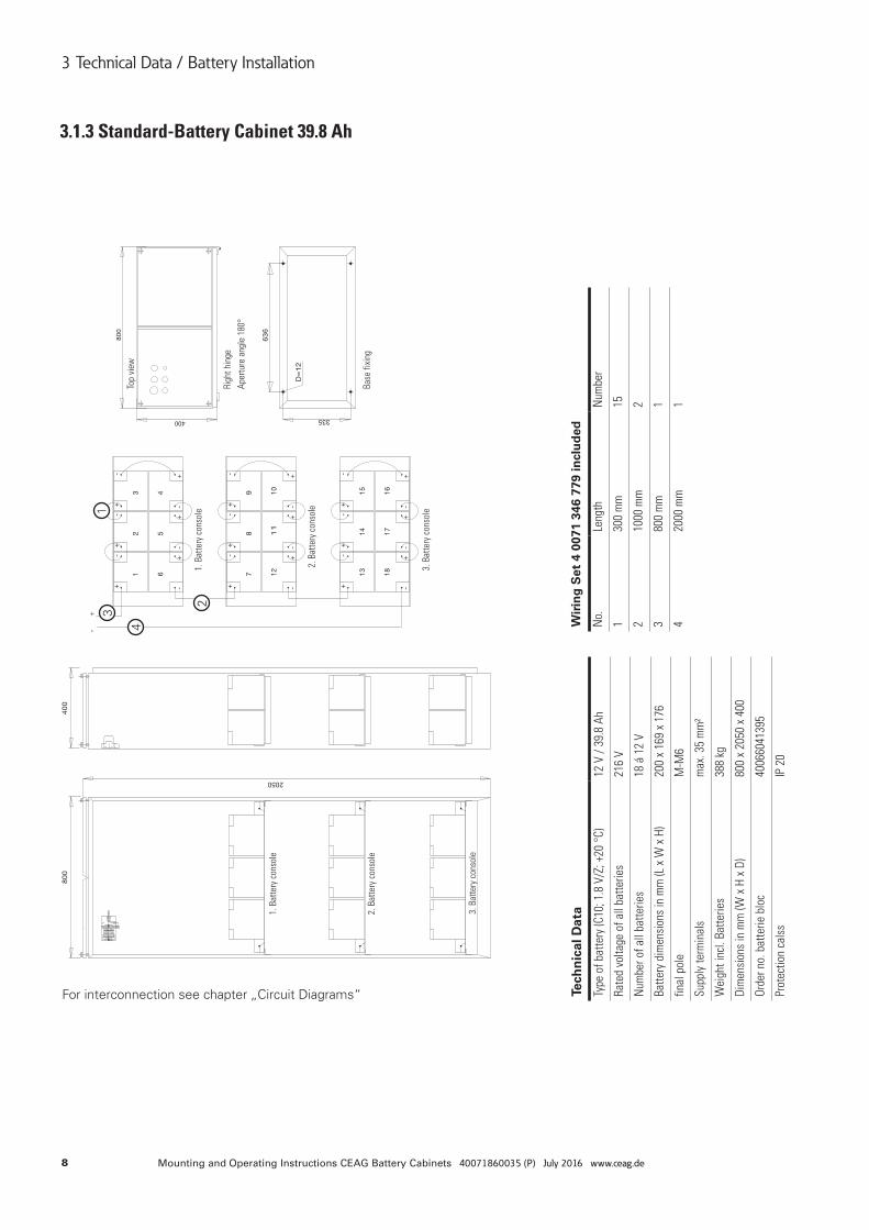
3.1.3 Standard-Battery Cabinet 39.8 Ah
For interconnection see chapter „Circuit Diagrams“
1
2
3
4
Tech
nic
al D
ata
Type
of b
atte
ry (C
10; 1
.8 V
/Z; +
20 °
C)12
V /
39.8
Ah
Rate
d vo
ltage
of a
ll ba
tterie
s21
6 V
Num
ber o
f all
batte
ries
18 á
12
V
Batte
ry d
imen
sion
s in
mm
(L x
W x
H)
200
x 16
9 x
176
final
pol
eM
-M6
Supp
ly te
rmin
als
max
. 35
mm
²
Wei
ght i
ncl.
Batte
ries
388
kg
Dim
ensi
ons
in m
m (W
x H
x D
)80
0 x
2050
x 4
00
Orde
r no.
bat
terie
blo
c40
0660
4139
5
Prot
ectio
n ca
lss
IP 2
0
Wir
ing
Set
4 0
071
346
779
incl
ud
ed
No.
Leng
thN
umbe
r
130
0 m
m15
210
00 m
m2
380
0 m
m1
420
00 m
m1
1. B
atte
ry c
onso
le
1. B
atte
ry c
onso
le
2. B
atte
ry c
onso
le
2. B
atte
ry c
onso
le
3. B
atte
ry c
onso
le
3. B
atte
ry c
onso
le
Righ
t hin
ge
Aper
ture
ang
le 1
80°
Base
fixi
ng
Top
view
9Mounting and Operating Instructions CEAG Battery Cabinets 40071860035 (P) July 2016 www.ceag.de
3 Technical Data / Battery Installation
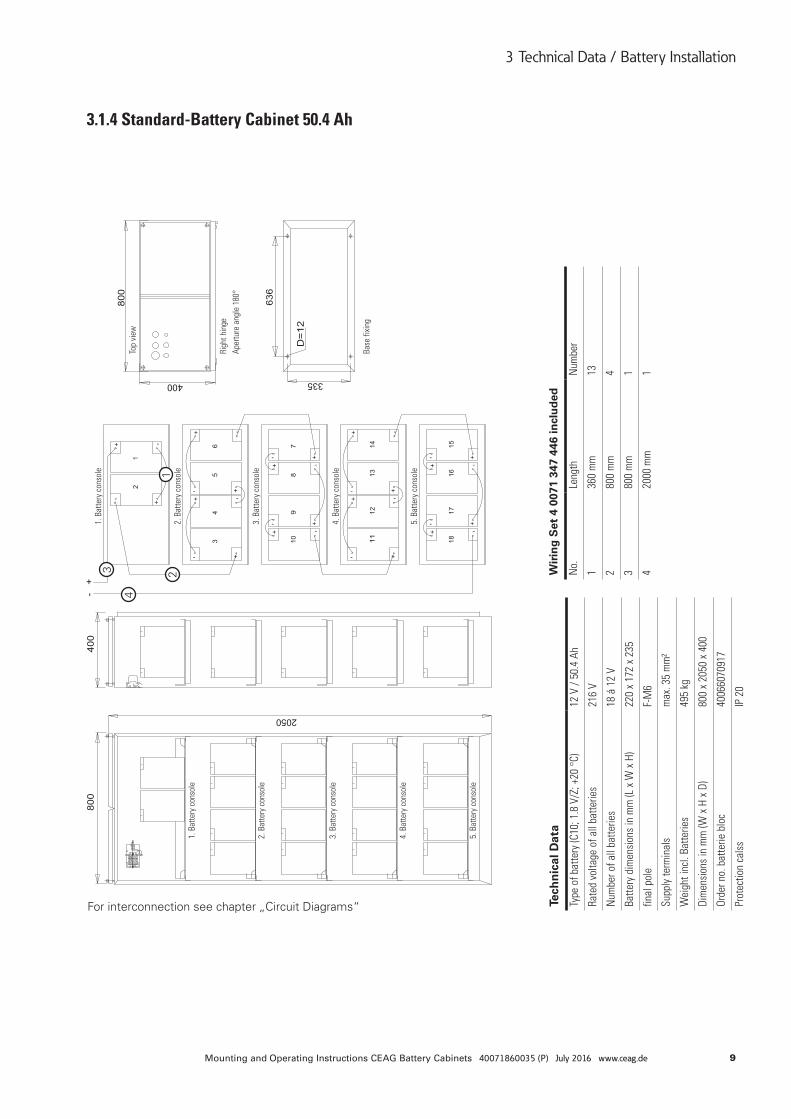
3.1.4 Standard-Battery Cabinet 50.4 Ah
For interconnection see chapter „Circuit Diagrams“
123
4
Tech
nic
al D
ata
Type
of b
atte
ry (C
10; 1
.8 V
/Z; +
20 °
C)12
V /
50.4
Ah
Rate
d vo
ltage
of a
ll ba
tterie
s21
6 V
Num
ber o
f all
batte
ries
18 á
12
V
Batte
ry d
imen
sion
s in
mm
(L x
W x
H)
220
x 17
2 x
235
final
pol
eF-
M6
Supp
ly te
rmin
als
max
. 35
mm
²
Wei
ght i
ncl.
Batte
ries
495
kg
Dim
ensi
ons
in m
m (W
x H
x D
)80
0 x
2050
x 4
00
Orde
r no.
bat
terie
blo
c40
0660
7091
7
Prot
ectio
n ca
lss
IP 2
0
Wir
ing
Set
4 0
071
347
446
incl
ud
ed
No.
Leng
thN
umbe
r
136
0 m
m13
280
0 m
m4
380
0 m
m1
420
00 m
m1
Righ
t hin
ge
Aper
ture
ang
le 1
80°
Top
view
Base
fixi
ng
1. B
atte
ry c
onso
le
1. B
atte
ry c
onso
le
2. B
atte
ry c
onso
le
2. B
atte
ry c
onso
le
3. B
atte
ry c
onso
le
3. B
atte
ry c
onso
le
4. B
atte
ry c
onso
le
4. B
atte
ry c
onso
le
5. B
atte
ry c
onso
le
5. B
atte
ry c
onso
le

10 Mounting and Operating Instructions CEAG Battery Cabinets 40071860035 (P) July 2016 www.ceag.de
3 Technical Data / Battery Installation
3.1.5 Standard-Battery Cabinet 53.7 Ah
For interconnection see chapter „Circuit Diagrams“
123
4
Tech
nic
al D
ata
Type
of b
atte
ry (C
10; 1
.8 V
/Z; +
20 °
C)12
V /
53.7
Ah
Rate
d vo
ltage
of a
ll ba
tterie
s21
6 V
Num
ber o
f all
batte
ries
18 á
12
V
Batte
ry d
imen
sion
s in
mm
(L x
W x
H)
220
x 17
2 x
235
final
pol
eF-
M6
Supp
ly te
rmin
als
max
. 35
mm
²
Wei
ght i
ncl.
Batte
ries
549
kg
Dim
ensi
ons
in m
m (W
x H
x D
)80
0 x
2050
x 4
00
Orde
r no.
bat
terie
blo
c40
0660
7090
1
Prot
ectio
n ca
lss
IP 2
0
Wir
ing
Set
4 0
071
347
446
incl
ud
ed
No.
Leng
thN
umbe
r
136
0 m
m13
280
0 m
m4
380
0 m
m1
420
00 m
m1
Righ
t hin
ge
Aper
ture
ang
le 1
80°
Top
view
Base
fixi
ng
1. B
atte
ry c
onso
le
1. B
atte
ry c
onso
le
2. B
atte
ry c
onso
le
2. B
atte
ry c
onso
le
3. B
atte
ry c
onso
le
3. B
atte
ry c
onso
le
4. B
atte
ry c
onso
le
4. B
atte
ry c
onso
le
5. B
atte
ry c
onso
le
5. B
atte
ry c
onso
le
11Mounting and Operating Instructions CEAG Battery Cabinets 40071860035 (P) July 2016 www.ceag.de
3 Technical Data / Battery Installation
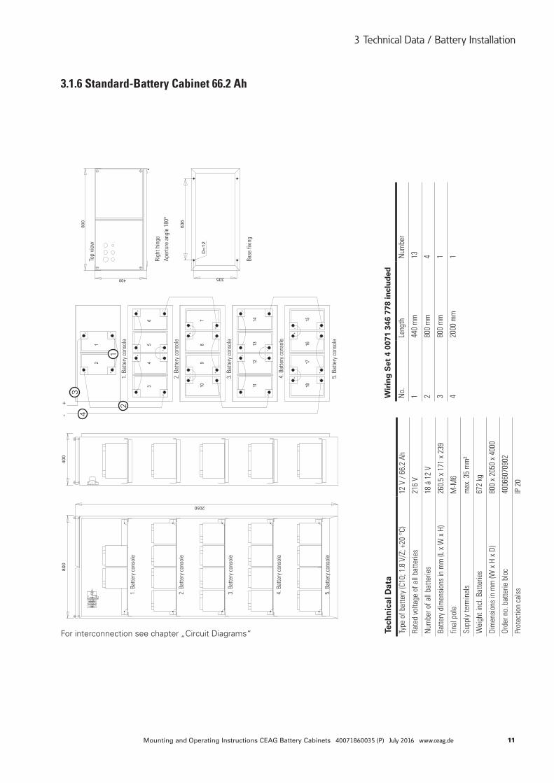
3.1.6 Standard-Battery Cabinet 66.2 Ah
For interconnection see chapter „Circuit Diagrams“
12
34
Tech
nic
al D
ata
Type
of b
atte
ry (C
10; 1
.8 V
/Z; +
20 °
C)12
V /
66.2
Ah
Rate
d vo
ltage
of a
ll ba
tterie
s21
6 V
Num
ber o
f all
batte
ries
18 á
12
V
Batte
ry d
imen
sion
s in
mm
(L x
W x
H)
260.
5 x
171
x 23
9
final
pol
eM
-M6
Supp
ly te
rmin
als
max
. 35
mm
²
Wei
ght i
ncl.
Batte
ries
672
kg
Dim
ensi
ons
in m
m (W
x H
x D
)80
0 x
2050
x 4
000
Orde
r no.
bat
terie
blo
c40
0660
7090
2
Prot
ectio
n ca
lss
IP 2
0
Wir
ing
Set
4 0
071
346
778
incl
ud
ed
No.
Leng
thN
umbe
r
144
0 m
m13
280
0 m
m4
380
0 m
m1
420
00 m
m1Righ
t hin
ge
Aper
ture
ang
le 1
80°
Top
view
Base
fixi
ng
1. B
atte
ry c
onso
le1.
Bat
tery
con
sole
2. B
atte
ry c
onso
le2.
Bat
tery
con
sole
3. B
atte
ry c
onso
le3.
Bat
tery
con
sole
4. B
atte
ry c
onso
le4.
Bat
tery
con
sole
5. B
atte
ry c
onso
le5.
Bat
tery
con
sole
12 Mounting and Operating Instructions CEAG Battery Cabinets 40071860035 (P) July 2016 www.ceag.de
3 Technical Data / Battery Installation
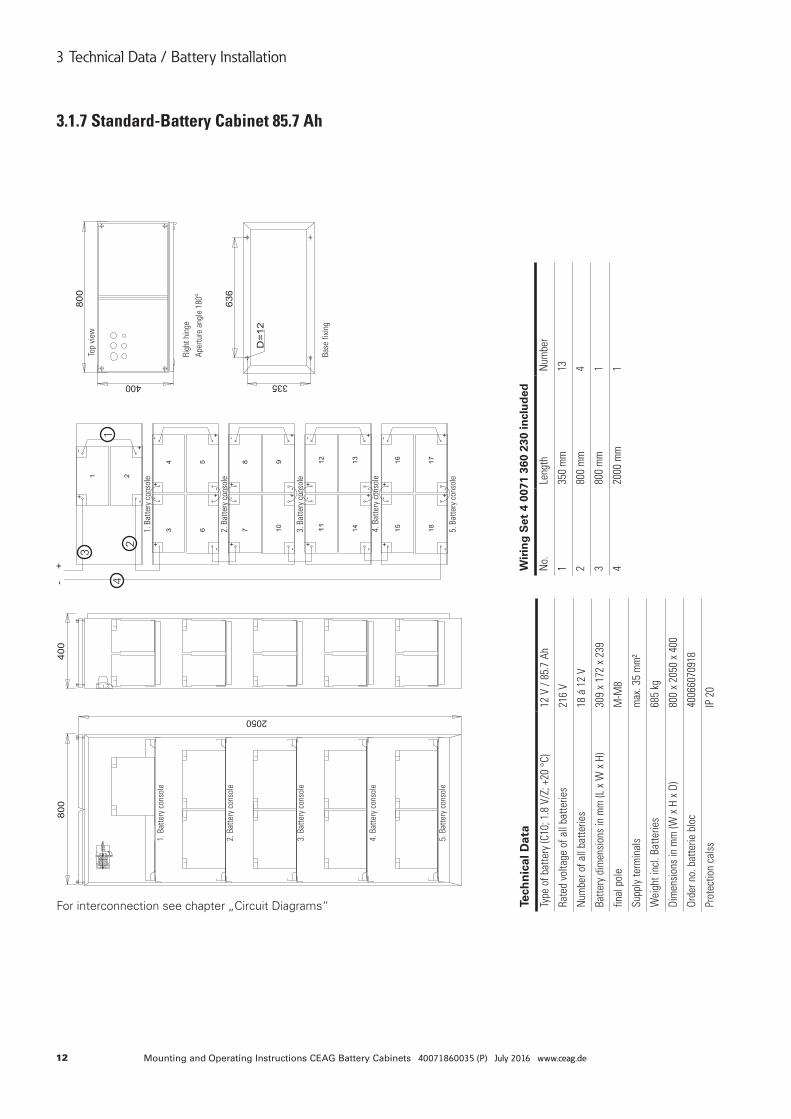
3.1.7 Standard-Battery Cabinet 85.7 Ah
For interconnection see chapter „Circuit Diagrams“
1
2
3
4
Tech
nic
al D
ata
Type
of b
atte
ry (C
10; 1
.8 V
/Z; +
20 °
C)12
V /
85.7
Ah
Rate
d vo
ltage
of a
ll ba
tterie
s21
6 V
Num
ber o
f all
batte
ries
18 á
12
V
Batte
ry d
imen
sion
s in
mm
(L x
W x
H)
309
x 17
2 x
239
final
pol
eM
-M8
Supp
ly te
rmin
als
max
. 35
mm
²
Wei
ght i
ncl.
Batte
ries
685
kg
Dim
ensi
ons
in m
m (W
x H
x D
)80
0 x
2050
x 4
00
Orde
r no.
bat
terie
blo
c40
0660
7091
8
Prot
ectio
n ca
lss
IP 2
0
Wir
ing
Set
4 0
071
360
230
incl
ud
ed
No.
Leng
thN
umbe
r
135
0 m
m13
280
0 m
m4
380
0 m
m1
420
00 m
m1
Righ
t hin
ge
Aper
ture
ang
le 1
80°
Top
view
Base
fixi
ng
1. B
atte
ry c
onso
le
1. B
atte
ry c
onso
le
2. B
atte
ry c
onso
le2.
Bat
tery
con
sole
3. B
atte
ry c
onso
le3.
Bat
tery
con
sole
4. B
atte
ry c
onso
le4.
Bat
tery
con
sole
5. B
atte
ry c
onso
le5.
Bat
tery
con
sole
13Mounting and Operating Instructions CEAG Battery Cabinets 40071860035 (P) July 2016 www.ceag.de
3 Technical Data / Battery Installation
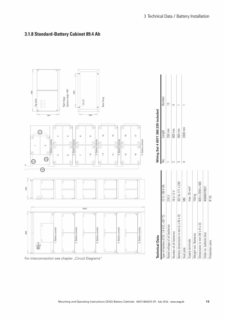
3.1.8 Standard-Battery Cabinet 89.4 Ah
For interconnection see chapter „Circuit Diagrams“
1
2
3
4
Tech
nic
al D
ata
Type
of b
atte
ry (C
10; 1
.8 V
/Z; +
20 °
C)12
V /
89.4
Ah
Rate
d vo
ltage
of a
ll ba
tterie
s21
6 V
Num
ber o
f all
batte
ries
18 á
12
V
Batte
ry d
imen
sion
s in
mm
(L x
W x
H)
307.
5x 1
71 x
239
final
pol
eM
6
Supp
ly te
rmin
als
max
. 35
mm
²
Wei
ght i
ncl.
Batte
ries
750
kg
Dim
ensi
ons
in m
m (W
x H
x D
)80
0 x
2050
x 4
00
Orde
r no.
bat
terie
blo
c40
0660
7082
1
Prot
ectio
n ca
lss
IP 2
0
Wir
ing
Set
4 0
071
360
230
incl
ud
ed
No.
Leng
thN
umbe
r
135
0 m
m13
280
0 m
m4
380
0 m
m1
420
00 m
m1Righ
t hin
ge
Aper
ture
ang
le 1
80°
Top
view
Base
fixi
ng
1. B
atte
ry c
onso
le
1. B
atte
ry c
onso
le
2. B
atte
ry c
onso
le2.
Bat
tery
con
sole
3. B
atte
ry c
onso
le3.
Bat
tery
con
sole
4. B
atte
ry c
onso
le4.
Bat
tery
con
sole
5. B
atte
ry c
onso
le5.
Bat
tery
con
sole
14 Mounting and Operating Instructions CEAG Battery Cabinets 40071860035 (P) July 2016 www.ceag.de
3 Technical Data / Battery Installation
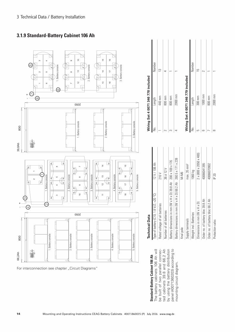
3.1.9 Standard-Battery Cabinet 106 Ah
For interconnection see chapter „Circuit Diagrams“
Stan
dard
-Bat
tery
Cab
inet
106
Ah
The
batt
ery
cabi
nets
106
Ah
will
be
bui
lt of
tw
o pa
ralle
l co
nnec
-te
d ca
bine
ts 3
9.8
and
66.2
Ah
by u
sing
the
bat
tery
dis
trib
utio
n pa
nel (
4007
1360
203)
acc
ordi
ng to
m
ount
ing
circ
uit
diag
ram
.
5
6
7
81
2
34
Tech
nic
al D
ata
Type
of b
atte
ry (C
10; 1
.8 V
/Z; +
20 °
C)12
V /
106
Ah
Rate
d vo
ltage
of a
ll ba
tterie
s21
6 V
Num
ber o
f all
batte
ries
36 á
12
V
Batte
ry d
imen
sion
s in
mm
(W x
H x
D) 3
9.8
Ah20
0 x
169
x 17
6
Batte
ry d
imen
sion
s in
mm
(W x
H x
D) 6
6.2
Ah26
0.5
x 17
1 x
239
final
pol
eM
-M6
Supp
ly te
rmin
als
max
. 35
mm
²
Wei
ght i
ncl.
Batte
ries
1060
kg
Dim
ensi
ons
in m
m (W
x H
x D
)2
x (8
00 x
205
0 x
400)
Orde
r no.
of b
atte
ry b
loc
39.8
Ah
4006
6041
395
Orde
r no.
of b
atte
ry b
loc
66.2
Ah
4006
6070
902
Prot
ectio
n ca
lss
IP 2
0
Wir
ing
Set
4 0
071
346
779
incl
ud
ed
No.
Leng
thN
umbe
r
530
0 m
m15
610
00 m
m2
780
0 m
m1
820
00 m
m1
Wir
ing
Set
4 0
071
346
778
incl
ud
ed
No.
Leng
thN
umbe
r
144
0 m
m13
280
0 m
m4
380
0 m
m1
420
00 m
m1
1. B
atte
ry c
onso
le1.
Bat
tery
con
sole
1. B
atte
ry c
onso
le
1. B
atte
ry c
onso
le
2. B
atte
ry c
onso
le2.
Bat
tery
con
sole
2. B
atte
ry c
onso
le
2. B
atte
ry c
onso
le3.
Bat
tery
con
sole
3. B
atte
ry c
onso
le
3. B
atte
ry c
onso
le
3. B
atte
ry c
onso
le
4. B
atte
ry c
onso
le4.
Bat
tery
con
sole
5. B
atte
ry c
onso
le5.
Bat
tery
con
sole
15Mounting and Operating Instructions CEAG Battery Cabinets 40071860035 (P) July 2016 www.ceag.de
3 Technical Data / Battery Installation
For interconnection see chapter „Circuit Diagrams“
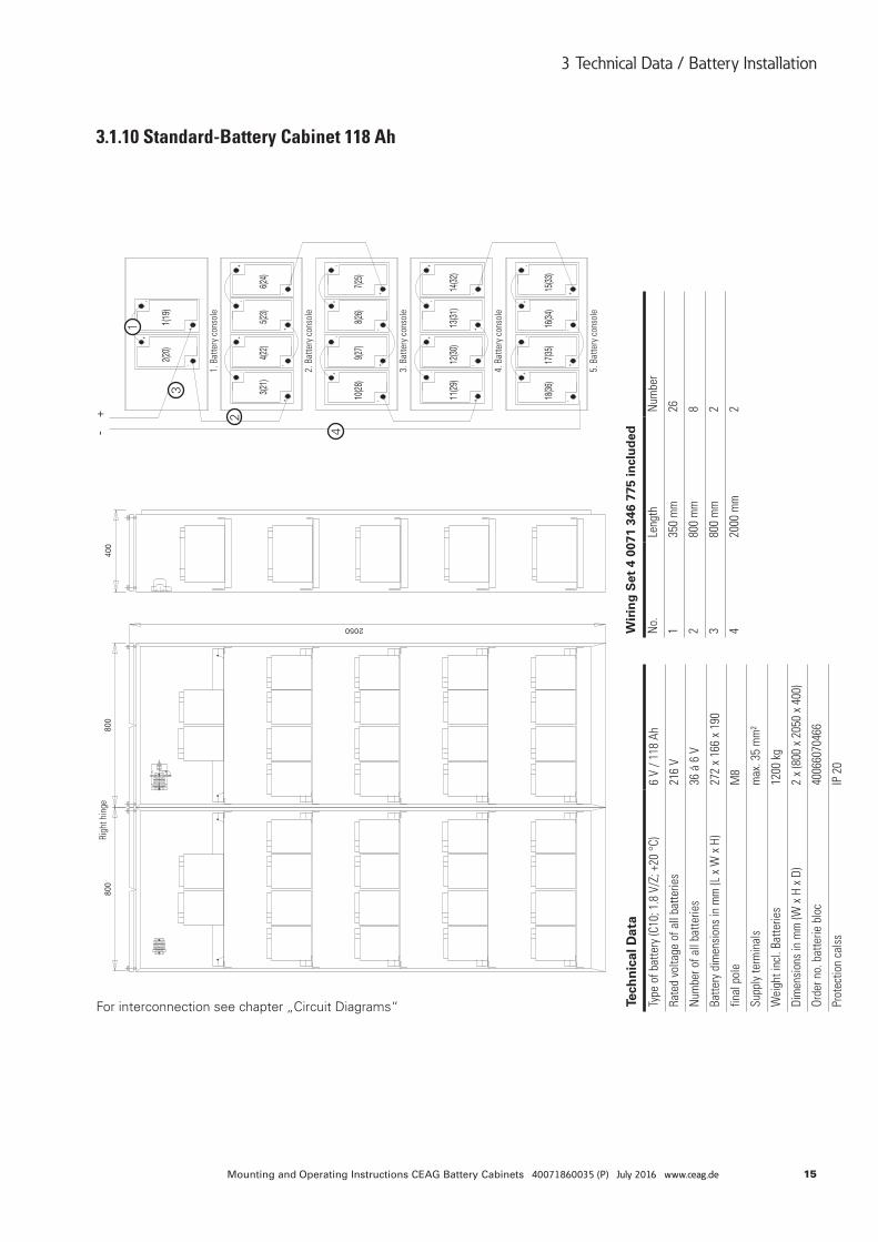
3.1.10 Standard-Battery Cabinet 118 Ah1
2
3
4
Tech
nic
al D
ata
Type
of b
atte
ry (C
10; 1
.8 V
/Z; +
20 °
C)6
V / 1
18 A
h
Rate
d vo
ltage
of a
ll ba
tterie
s21
6 V
Num
ber o
f all
batte
ries
36 á
6 V
Batte
ry d
imen
sion
s in
mm
(L x
W x
H)
272
x 16
6 x
190
final
pol
eM
8
Supp
ly te
rmin
als
max
. 35
mm
²
Wei
ght i
ncl.
Batte
ries
1200
kg
Dim
ensi
ons
in m
m (W
x H
x D
)2
x (8
00 x
205
0 x
400)
Orde
r no.
bat
terie
blo
c40
0660
7046
6
Prot
ectio
n ca
lss
IP 2
0
Wir
ing
Set
4 0
071
346
775
incl
ud
ed
No.
Leng
thN
umbe
r
135
0 m
m26
280
0 m
m8
380
0 m
m2
420
00 m
m2
1. B
atte
ry c
onso
le
Righ
t hin
ge
2. B
atte
ry c
onso
le
3. B
atte
ry c
onso
le
4. B
atte
ry c
onso
le
5. B
atte
ry c
onso
le
16 Mounting and Operating Instructions CEAG Battery Cabinets 40071860035 (P) July 2016 www.ceag.de
3 Technical Data / Battery Installation
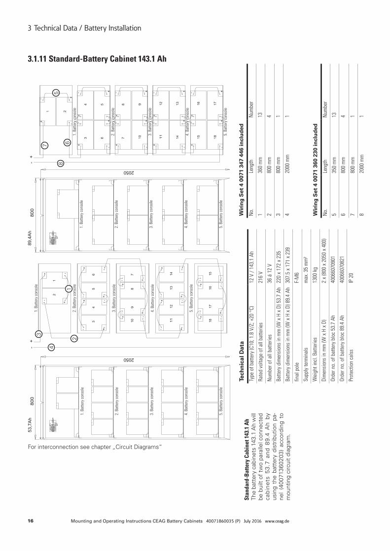
3.1.11 Standard-Battery Cabinet 143.1 Ah
For interconnection see chapter „Circuit Diagrams“
12
3
45
67
8
Stan
dard
-Bat
tery
Cab
inet
143
.1 A
hTh
e ba
tter
y ca
bine
ts 1
43.1
Ah
will
be
bui
lt of
tw
o pa
ralle
l con
nect
ed
cabi
nets
53.
7 an
d 89
.4 A
h by
us
ing
the
batt
ery
dist
ribut
ion
pa-
nel
(400
7136
0203
) ac
cord
ing
to
mou
ntin
g ci
rcui
t di
agra
m.
Tech
nic
al D
ata
Type
of b
atte
ry (C
10; 1
.8 V
/Z; +
20 °
C)12
V /
143.
1 Ah
Rate
d vo
ltage
of a
ll ba
tterie
s21
6 V
Num
ber o
f all
batte
ries
36 á
12
V
Batte
ry d
imen
sion
s in
mm
(W x
H x
D) 5
3.7
Ah22
0 x
172
x 23
5
Batte
ry d
imen
sion
s in
mm
(W x
H x
D) 8
9.4
Ah30
7.5
x 17
1 x
239
final
pol
eF-
M6
Supp
ly te
rmin
als
max
. 35
mm
²
Wei
ght i
ncl.
Batte
ries
1300
kg
Dim
ensi
ons
in m
m (W
x H
x D
)2
x (8
00 x
205
0 x
400)
Orde
r no.
of b
atte
ry b
loc
53.7
Ah
4006
6070
901
Orde
r no.
of b
atte
ry b
loc
89.4
Ah
4006
6070
821
Prot
ectio
n ca
lss
IP 2
0
Wir
ing
Set
4 0
071
347
446
incl
ud
ed
No.
Leng
thN
umbe
r
136
0 m
m13
280
0 m
m4
380
0 m
m1
420
00 m
m1
Wir
ing
Set
4 0
071
360
230
incl
ud
ed
No.
Leng
thN
umbe
r
535
0 m
m13
680
0 m
m4
780
0 m
m1
820
00 m
m1
1. B
atte
ry c
onso
le
1. B
atte
ry c
onso
le
1. B
atte
ry c
onso
le
1. B
atte
ry c
onso
le
2. B
atte
ry c
onso
le
2. B
atte
ry c
onso
le
2. B
atte
ry c
onso
le2.
Bat
tery
con
sole
3. B
atte
ry c
onso
le
3. B
atte
ry c
onso
le
3. B
atte
ry c
onso
le3.
Bat
tery
con
sole
4. B
atte
ry c
onso
le
4. B
atte
ry c
onso
le
4. B
atte
ry c
onso
le4.
Bat
tery
con
sole
5. B
atte
ry c
onso
le
5. B
atte
ry c
onso
le
5. B
atte
ry c
onso
le5.
Bat
tery
con
sole
17Mounting and Operating Instructions CEAG Battery Cabinets 40071860035 (P) July 2016 www.ceag.de
3 Technical Data / Battery Installation
Wir
ing
Set
4 0
071
360
230
incl
ud
ed
No.
Leng
thN
umbe
r
535
0 m
m13
680
0 m
m4
780
0 m
m1
820
00 m
m1
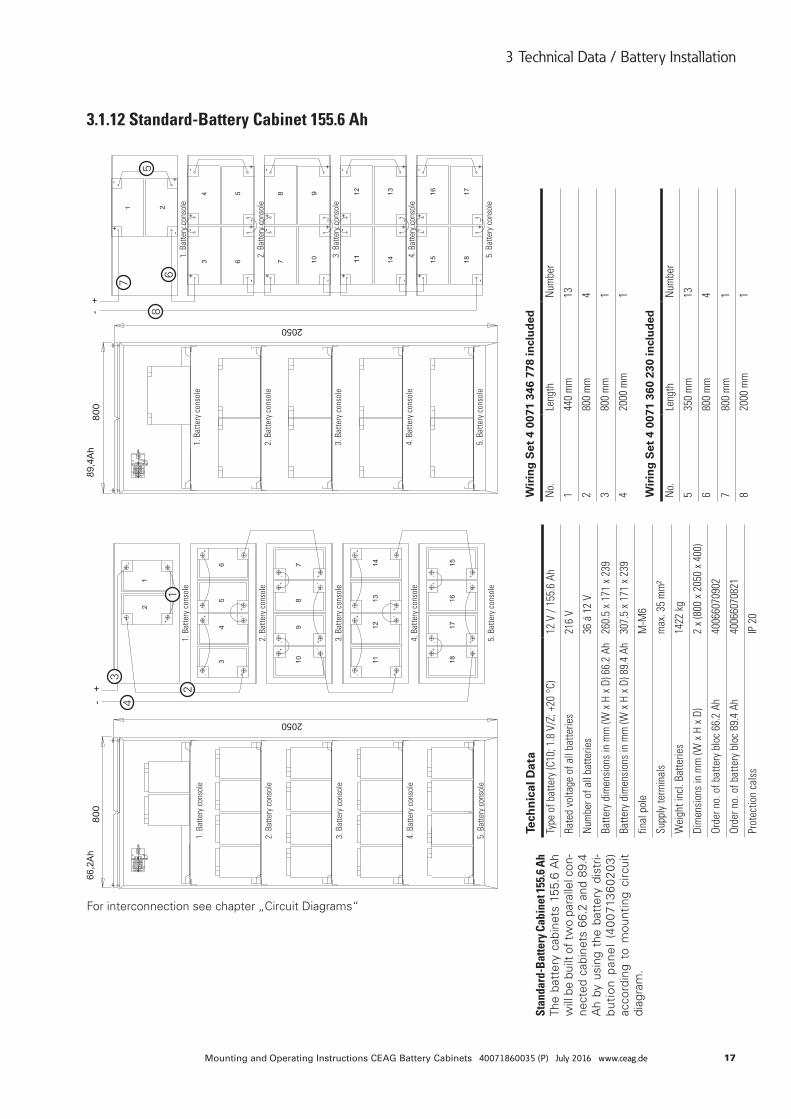
3.1.12 Standard-Battery Cabinet 155.6 Ah
For interconnection see chapter „Circuit Diagrams“
Stan
dard
-Bat
tery
Cab
inet
155.
6 Ah
The
batt
ery
cabi
nets
155
.6 A
h w
ill b
e bu
ilt o
f tw
o pa
ralle
l con
-ne
cted
cab
inet
s 66
.2 a
nd 8
9.4
Ah
by u
sing
the
bat
tery
dis
tri-
buti
on p
anel
(40
0713
6020
3)
acco
rdin
g to
mou
ntin
g ci
rcui
t di
agra
m.
12
34
5
6
7
8
Tech
nic
al D
ata
Type
of b
atte
ry (C
10; 1
.8 V
/Z; +
20 °
C)12
V /
155.
6 Ah
Rate
d vo
ltage
of a
ll ba
tterie
s21
6 V
Num
ber o
f all
batte
ries
36 á
12
V
Batte
ry d
imen
sion
s in
mm
(W x
H x
D) 6
6.2
Ah26
0.5
x 17
1 x
239
Batte
ry d
imen
sion
s in
mm
(W x
H x
D) 8
9.4
Ah30
7.5
x 17
1 x
239
final
pol
eM
-M6
Supp
ly te
rmin
als
max
. 35
mm
²
Wei
ght i
ncl.
Batte
ries
1422
kg
Dim
ensi
ons
in m
m (W
x H
x D
)2
x (8
00 x
205
0 x
400)
Orde
r no.
of b
atte
ry b
loc
66.2
Ah
4006
6070
902
Orde
r no.
of b
atte
ry b
loc
89.4
Ah
4006
6070
821
Prot
ectio
n ca
lss
IP 2
0
Wir
ing
Set
4 0
071
346
778
incl
ud
ed
No.
Leng
thN
umbe
r
144
0 m
m13
280
0 m
m4
380
0 m
m1
420
00 m
m1
Wir
ing
Set
4 0
071
360
230
incl
ud
ed
No.
Leng
thN
umbe
r
535
0 m
m13
680
0 m
m4
780
0 m
m1
820
00 m
m1
1. B
atte
ry c
onso
le
1. B
atte
ry c
onso
le1.
Bat
tery
con
sole
1. B
atte
ry c
onso
le
2. B
atte
ry c
onso
le2.
Bat
tery
con
sole
2. B
atte
ry c
onso
le2.
Bat
tery
con
sole
3. B
atte
ry c
onso
le3.
Bat
tery
con
sole
3. B
atte
ry c
onso
le3.
Bat
tery
con
sole
4. B
atte
ry c
onso
le4.
Bat
tery
con
sole
4. B
atte
ry c
onso
le4.
Bat
tery
con
sole
5. B
atte
ry c
onso
le5.
Bat
tery
con
sole
5. B
atte
ry c
onso
le5.
Bat
tery
con
sole
18 Mounting and Operating Instructions CEAG Battery Cabinets 40071860035 (P) July 2016 www.ceag.de
3 Technical Data / Battery Installation
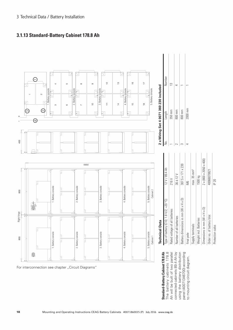
3.1.13 Standard-Battery Cabinet 178.8 Ah
Stan
dard
-Bat
tery
Cab
inet
178.
8 Ah
The
bat
tery
cab
ine
ts 1
78
.8
Ah
will
be
built
of
two
para
llel
conn
ecte
d ca
bine
ts 8
9.4
Ah
by
usin
g th
e ba
tter
y di
strib
utio
n pa
nel (
4007
1346
700)
acc
ordi
ng
to m
ount
ing
circ
uit
diag
ram
.
For interconnection see chapter „Circuit Diagrams“
1
23
4
Tech
nic
al D
ata
Type
of b
atte
ry (C
10; 1
.8 V
/Z; +
20 °
C)12
V /
89.4
Ah
Rate
d vo
ltage
of a
ll ba
tterie
s21
6 V
Num
ber o
f all
batte
ries
36 á
12
V
Batte
ry d
imen
sion
s in
mm
(W x
H x
D)
307.
5 x
171
x 23
9
final
pol
eM
6
Supp
ly te
rmin
als
max
. 35
mm
²
Wei
ght i
ncl.
Batte
ries
1500
kg
Dim
ensi
ons
in m
m (W
x H
x D
)2
x (8
00 x
205
0 x
400)
Orde
r no.
of b
atte
ry b
loc
4006
6070
821
Prot
ectio
n ca
lss
IP 2
0
2 x
Wir
ing
Set
4 0
071
360
230
incl
ud
ed
No.
Leng
thN
umbe
r
135
0 m
m13
280
0 m
m4
380
0 m
m1
420
00 m
m1
1. B
atte
ry c
onso
le1.
Bat
tery
con
sole
1. B
atte
ry c
onso
le
Righ
t hin
ge
2. B
atte
ry c
onso
le2.
Bat
tery
con
sole
2. B
atte
ry c
onso
le
3. B
atte
ry c
onso
le3.
Bat
tery
con
sole
3. B
atte
ry c
onso
le
4. B
atte
ry c
onso
le4.
Bat
tery
con
sole
4. B
atte
ry c
onso
le
5. B
atte
ry c
onso
le
Cabi
net 1
Cabi
net 2
5. B
atte
ry c
onso
le5.
Bat
tery
con
sole
19Mounting and Operating Instructions CEAG Battery Cabinets 40071860035 (P) July 2016 www.ceag.de
3 Technical Data / Battery Installation
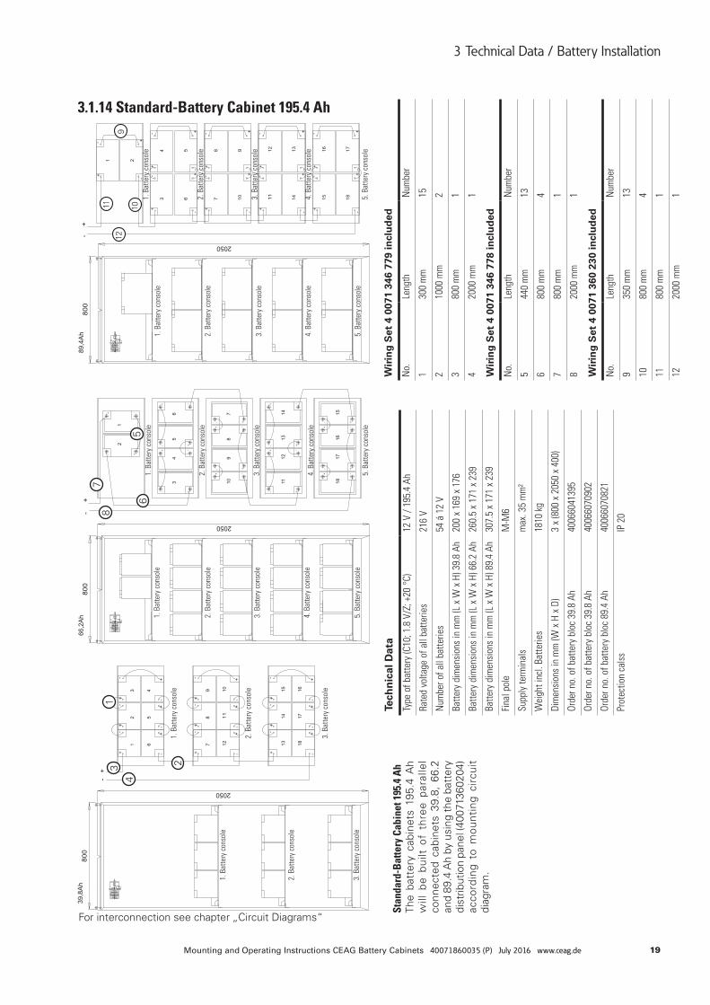
3.1.14 Standard-Battery Cabinet 195.4 Ah
Stan
dard
-Bat
tery
Cab
inet
195
.4 A
hTh
e ba
tter
y ca
bine
ts 1
95.4
Ah
will
be
built
of
thre
e pa
ralle
l co
nnec
ted
cabi
nets
39.
8, 6
6.2
and
89.4
Ah
by u
sing
the
batt
ery
dist
ribut
ion
pane
l (40
0713
6020
4)
acco
rdin
g to
mou
ntin
g ci
rcui
t di
agra
m.
For interconnection see chapter „Circuit Diagrams“
1
234
56
78
9
101112
Tech
nic
al D
ata
Type
of b
atte
ry (C
10; 1
.8 V
/Z; +
20 °
C)12
V /
195.
4 Ah
Rate
d vo
ltage
of a
ll ba
tterie
s21
6 V
Num
ber o
f all
batte
ries
54 á
12
V
Batte
ry d
imen
sion
s in
mm
(L x
W x
H) 3
9.8
Ah20
0 x
169
x 17
6
Batte
ry d
imen
sion
s in
mm
(L x
W x
H) 6
6.2
Ah26
0.5
x 17
1 x
239
Batte
ry d
imen
sion
s in
mm
(L x
W x
H) 8
9.4
Ah30
7.5
x 17
1 x
239
Fina
l pol
eM
-M6
Supp
ly te
rmin
als
max
. 35
mm
²
Wei
ght i
ncl.
Batte
ries
1810
kg
Dim
ensi
ons
in m
m (W
x H
x D
)3
x (8
00 x
205
0 x
400)
Orde
r no.
of b
atte
ry b
loc
39.8
Ah
4006
6041
395
Orde
r no.
of b
atte
ry b
loc
39.8
Ah
4006
6070
902
Orde
r no.
of b
atte
ry b
loc
89.4
Ah
4006
6070
821
Prot
ectio
n ca
lss
IP 2
0
Wir
ing
Set
4 0
071
346
779
incl
ud
ed
No.
Leng
thN
umbe
r
130
0 m
m15
210
00 m
m2
380
0 m
m1
420
00 m
m1
Wir
ing
Set
4 0
071
346
778
incl
ud
ed
No.
Leng
thN
umbe
r
544
0 m
m13
680
0 m
m4
780
0 m
m1
820
00 m
m1
Wir
ing
Set
4 0
071
360
230
incl
ud
ed
No.
Leng
thN
umbe
r
935
0 m
m13
1080
0 m
m4
1180
0 m
m1
1220
00 m
m1
1. B
atte
ry c
onso
le1.
Bat
tery
con
sole
1. B
atte
ry c
onso
le
1. B
atte
ry c
onso
le
1. B
atte
ry c
onso
le
1. B
atte
ry c
onso
le
2. B
atte
ry c
onso
le2.
Bat
tery
con
sole
2. B
atte
ry c
onso
le2.
Bat
tery
con
sole
2. B
atte
ry c
onso
le
2. B
atte
ry c
onso
le3.
Bat
tery
con
sole
3. B
atte
ry c
onso
le3.
Bat
tery
con
sole
3. B
atte
ry c
onso
le
3. B
atte
ry c
onso
le
3. B
atte
ry c
onso
le
4. B
atte
ry c
onso
le4.
Bat
tery
con
sole
4. B
atte
ry c
onso
le4.
Bat
tery
con
sole
5. B
atte
ry c
onso
le5.
Bat
tery
con
sole
5. B
atte
ry c
onso
le5.
Bat
tery
con
sole
20 Mounting and Operating Instructions CEAG Battery Cabinets 40071860035 (P) July 2016 www.ceag.de
3 Technical Data / Battery Installation
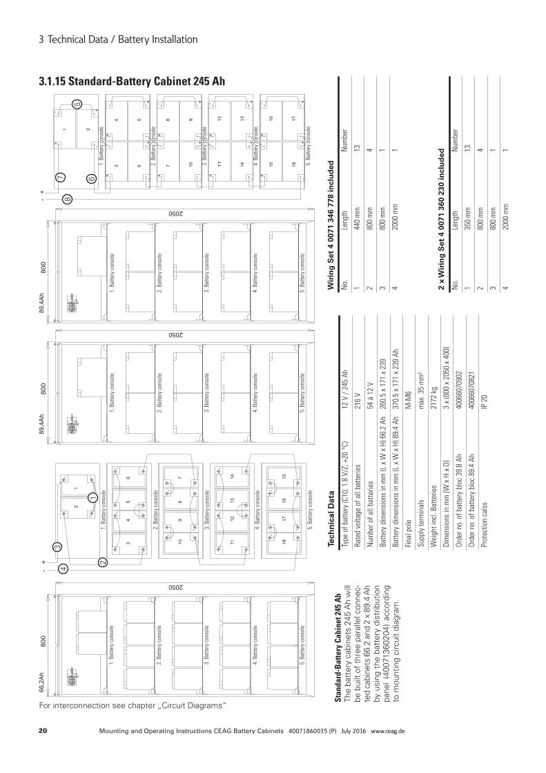
3.1.15 Standard-Battery Cabinet 245 Ah
Stan
dard
-Bat
tery
Cab
inet
245
Ah
The
batt
ery
cabi
nets
245
Ah
will
be
bui
lt of
thre
e pa
ralle
l con
nec-
ted
cabi
nets
66.
2 an
d 2
x 89
.4 A
h by
usi
ng t
he b
atte
ry d
istr
ibut
ion
pane
l (4
0071
3602
04)
acco
rdin
g to
mou
ntin
g ci
rcui
t di
agra
m.
For interconnection see chapter „Circuit Diagrams“
12
34
5
678
Tech
nic
al D
ata
Type
of b
atte
ry (C
10; 1
.8 V
/Z; +
20 °
C)12
V /
245
Ah
Rate
d vo
ltage
of a
ll ba
tterie
s21
6 V
Num
ber o
f all
batte
ries
54 á
12
V
Batte
ry d
imen
sion
s in
mm
(L x
W x
H) 6
6.2
Ah26
0.5
x 17
1 x
239
Batte
ry d
imen
sion
s in
mm
(L x
W x
H) 8
9.4
Ah37
0.5
x 17
1 x
239
Ah
Fina
l pol
eM
-M6
Supp
ly te
rmin
als
max
. 35
mm
²
Wei
ght i
ncl.
Batte
ries
2172
kg
Dim
ensi
ons
in m
m (W
x H
x D
)3
x (8
00 x
205
0 x
400)
Orde
r no.
of b
atte
ry b
loc
39.8
Ah
4006
6070
902
Orde
r no.
of b
atte
ry b
loc
89.4
Ah
4006
6070
821
Prot
ectio
n ca
lss
IP 2
0
Wir
ing
Set
4 0
071
346
778
incl
ud
ed
No.
Leng
thN
umbe
r
144
0 m
m13
280
0 m
m4
380
0 m
m1
420
00 m
m1
2 x
Wir
ing
Set
4 0
071
360
230
incl
ud
ed
No.
Leng
thN
umbe
r
135
0 m
m13
280
0 m
m4
380
0 m
m1
420
00 m
m1
1. B
atte
ry c
onso
le1.
Bat
tery
con
sole
1. B
atte
ry c
onso
le1.
Bat
tery
con
sole
1. B
atte
ry c
onso
le
2. B
atte
ry c
onso
le2.
Bat
tery
con
sole
2. B
atte
ry c
onso
le2.
Bat
tery
con
sole
2. B
atte
ry c
onso
le
3. B
atte
ry c
onso
le3.
Bat
tery
con
sole
3. B
atte
ry c
onso
le3.
Bat
tery
con
sole
3. B
atte
ry c
onso
le
4. B
atte
ry c
onso
le4.
Bat
tery
con
sole
4. B
atte
ry c
onso
le4.
Bat
tery
con
sole
4. B
atte
ry c
onso
le
5. B
atte
ry c
onso
le5.
Bat
tery
con
sole
5. B
atte
ry c
onso
le5.
Bat
tery
con
sole
5. B
atte
ry c
onso
le
21Mounting and Operating Instructions CEAG Battery Cabinets 40071860035 (P) July 2016 www.ceag.de
3 Technical Data / Battery Installation
2 x
Wir
ing
Set
4 0
071
360
230
incl
ud
ed
No.
Leng
thN
umbe
r
135
0 m
m13
280
0 m
m4
380
0 m
m1
420
00 m
m1
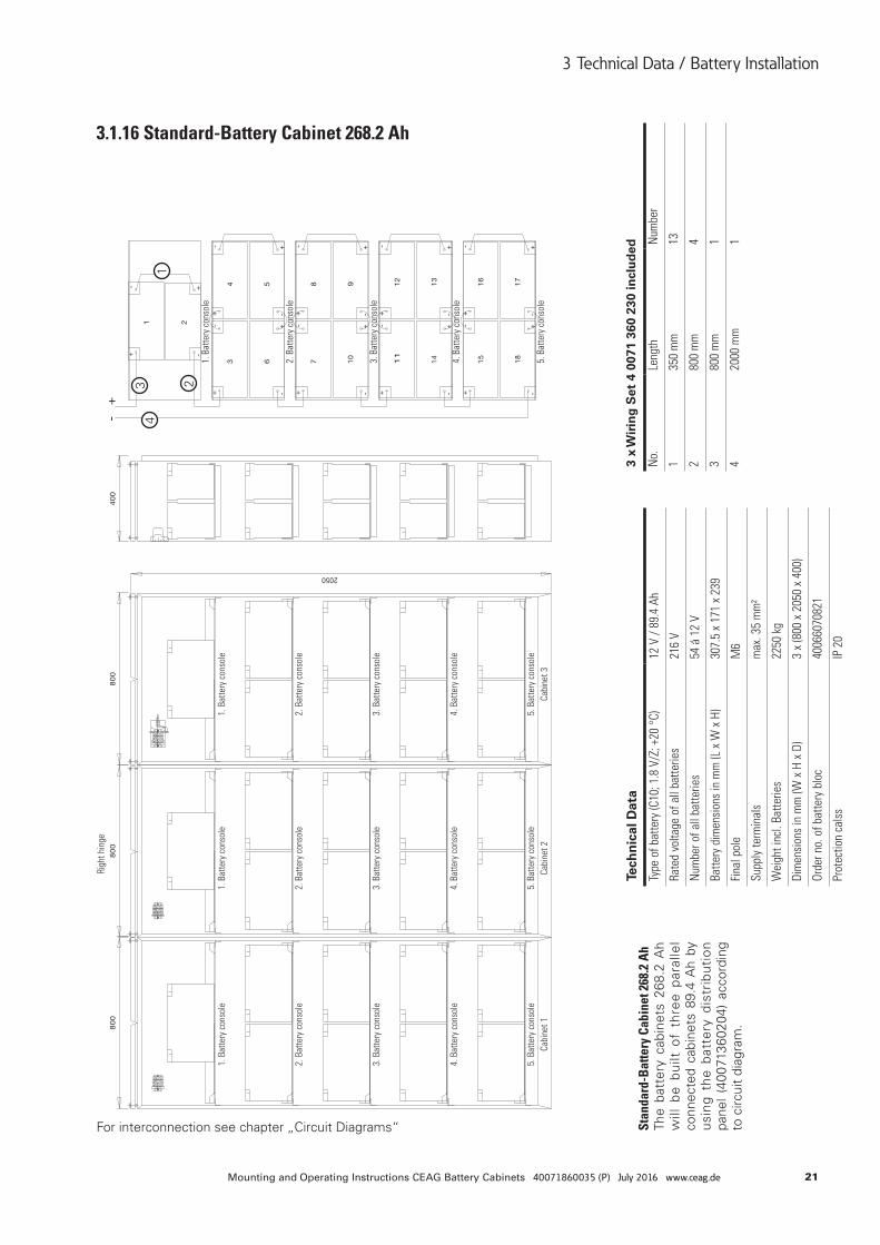
3.1.16 Standard-Battery Cabinet 268.2 Ah
Stan
dard
-Bat
tery
Cab
inet
268
.2 A
hTh
e ba
tter
y ca
bine
ts 2
68.2
Ah
will
be
built
of
thre
e pa
ralle
l co
nnec
ted
cabi
nets
89.
4 A
h by
us
ing
the
batt
ery
dist
ribu
tion
pa
nel
(400
7136
0204
) ac
cord
ing
to c
ircui
t di
agra
m.
For interconnection see chapter „Circuit Diagrams“
1
234
Tech
nic
al D
ata
Type
of b
atte
ry (C
10; 1
.8 V
/Z; +
20 °
C)12
V /
89.4
Ah
Rate
d vo
ltage
of a
ll ba
tterie
s21
6 V
Num
ber o
f all
batte
ries
54 á
12
V
Batte
ry d
imen
sion
s in
mm
(L x
W x
H)
307.
5 x
171
x 23
9
Fina
l pol
eM
6
Supp
ly te
rmin
als
max
. 35
mm
²
Wei
ght i
ncl.
Batte
ries
2250
kg
Dim
ensi
ons
in m
m (W
x H
x D
)3
x (8
00 x
205
0 x
400)
Orde
r no.
of b
atte
ry b
loc
4006
6070
821
Prot
ectio
n ca
lss
IP 2
0
3 x
Wir
ing
Set
4 0
071
360
230
incl
ud
ed
No.
Leng
thN
umbe
r
135
0 m
m13
280
0 m
m4
380
0 m
m1
420
00 m
m1
1. B
atte
ry c
onso
le1.
Bat
tery
con
sole
Righ
t hin
ge
1. B
atte
ry c
onso
le
1. B
atte
ry c
onso
le
2. B
atte
ry c
onso
le2.
Bat
tery
con
sole
2. B
atte
ry c
onso
le2.
Bat
tery
con
sole
3. B
atte
ry c
onso
le3.
Bat
tery
con
sole
3. B
atte
ry c
onso
le3.
Bat
tery
con
sole
4. B
atte
ry c
onso
le4.
Bat
tery
con
sole
4. B
atte
ry c
onso
le4.
Bat
tery
con
sole
5. B
atte
ry c
onso
le5.
Bat
tery
con
sole
5. B
atte
ry c
onso
le5.
Bat
tery
con
sole
Cabi
net 1
Cabi
net 2
Cabi
net 3
22 Mounting and Operating Instructions CEAG Battery Cabinets 40071860035 (P) July 2016 www.ceag.de
3 Technical Data / Battery Installation
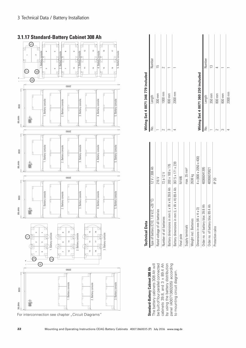
3.1.17 Standard-Battery Cabinet 308 Ah
Stan
dard
-Bat
tery
Cab
inet
308
Ah
The
batt
ery
cabi
nets
308
Ah
will
be
bui
lt of
four
par
alle
l con
nect
ed
cabi
nets
39.
8, a
nd 3
x 8
9.4
Ah
by u
sing
the
bat
tery
dis
trib
utio
n pa
nel
(400
7136
0205
) ac
cord
ing
to m
ount
ing
circ
uit
diag
ram
.
For interconnection see chapter „Circuit Diagrams“
1
23
4
5
67
8
Tech
nic
al D
ata
Type
of b
atte
ry (C
10; 1
.8 V
/Z; +
20 °
C)12
V /
308
Ah
Rate
d vo
ltage
of a
ll ba
tterie
s21
6 V
Num
ber o
f all
batte
ries
72 á
12
V
Batte
ry d
imen
sion
s in
mm
(L x
W x
H) 3
9.8
Ah20
0 x
169
x 17
6
Batte
ry d
imen
sion
s in
mm
(L x
W x
H) 8
9.4
Ah30
7.5
x 17
1 x
239
Fina
l pol
eM
-M6
Supp
ly te
rmin
als
max
. 35
mm
²
Wei
ght i
ncl.
Batte
ries
2638
kg
Dim
ensi
ons
in m
m (W
x H
x D
)4
x (8
00 x
205
0 x
400)
Orde
r no.
of b
atte
ry b
loc
39.8
Ah
4006
6041
395
Orde
r no.
of b
atte
ry b
loc
89.4
Ah
4006
6070
821
Prot
ectio
n ca
lss
IP 2
0
Wir
ing
Set
4 0
071
346
779
incl
ud
ed
No.
Leng
thN
umbe
r
130
0 m
m15
210
00 m
m2
380
0 m
m1
420
00 m
m1
Wir
ing
Set
4 0
071
360
230
incl
ud
ed
No.
Leng
thN
umbe
r
135
0 m
m13
280
0 m
m4
380
0 m
m1
420
00 m
m1
1. B
atte
ry c
onso
le
1. B
atte
ry c
onso
le
1. B
atte
ry c
onso
le
1. B
atte
ry c
onso
le1.
Bat
tery
con
sole
1. B
atte
ry c
onso
le
2. B
atte
ry c
onso
le
2. B
atte
ry c
onso
le
2. B
atte
ry c
onso
le
2. B
atte
ry c
onso
le2.
Bat
tery
con
sole
2. B
atte
ry c
onso
le
3. B
atte
ry c
onso
le
3. B
atte
ry c
onso
le
3. B
atte
ry c
onso
le
3. B
atte
ry c
onso
le3.
Bat
tery
con
sole
3. B
atte
ry c
onso
le
4. B
atte
ry c
onso
le4.
Bat
tery
con
sole
4. B
atte
ry c
onso
le4.
Bat
tery
con
sole
5. B
atte
ry c
onso
le5.
Bat
tery
con
sole
5. B
atte
ry c
onso
le5.
Bat
tery
con
sole
23Mounting and Operating Instructions CEAG Battery Cabinets 40071860035 (P) July 2016 www.ceag.de
3 Technical Data / Battery Installation
Wir
ing
Set
4 0
071
360
230
incl
ud
ed
No.
Leng
thN
umbe
r
135
0 m
m13
280
0 m
m4
380
0 m
m1
420
00 m
m1
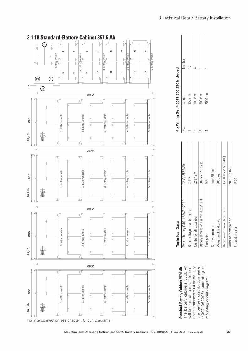
3.1.18 Standard-Battery Cabinet 357.6 Ah
Stan
dard
-Bat
tery
Cab
inet
357
.6 A
hTh
e ba
tter
y ca
bine
ts 3
57.6
Ah
will
be
built
of
four
par
alle
l con
-ne
cted
cab
inet
s 89
.4 A
h by
usi
ng
the
batt
ery
dist
ribu
tion
pan
el
(40
071
36
02
05
) ac
cord
ing
to
mou
ntin
g ci
rcui
t di
agra
m.
For interconnection see chapter „Circuit Diagrams“
1
234
Tech
nic
al D
ata
Type
of b
atte
ry (C
10; 1
.8 V
/Z; +
20 °
C)12
V /
357.
6 Ah
Rate
d vo
ltage
of a
ll ba
tterie
s21
6 V
Num
ber o
f all
batte
ries
72 á
12
V
Batte
ry d
imen
sion
s in
mm
(L x
W x
H)
307.
5 x
171
x 23
9
Fina
l pol
eM
6
Supp
ly te
rmin
als
max
. 35
mm
²
Wei
ght i
ncl.
Batte
ries
3000
kg
Dim
ensi
ons
in m
m (W
x H
x D
)4
x (8
00 x
205
0 x
400)
Orde
r no.
bat
terie
blo
c40
0660
7082
1
Prot
ectio
n ca
lss
IP 2
0
4 x
Wir
ing
Set
4 0
071
360
230
incl
ud
ed
No.
Leng
thN
umbe
r
135
0 m
m13
280
0 m
m4
380
0 m
m1
420
00 m
m1
1. B
atte
ry c
onso
le1.
Bat
tery
con
sole
1. B
atte
ry c
onso
le1.
Bat
tery
con
sole
1. B
atte
ry c
onso
le
2. B
atte
ry c
onso
le2.
Bat
tery
con
sole
2. B
atte
ry c
onso
le2.
Bat
tery
con
sole
2. B
atte
ry c
onso
le
3. B
atte
ry c
onso
le3.
Bat
tery
con
sole
3. B
atte
ry c
onso
le3.
Bat
tery
con
sole
3. B
atte
ry c
onso
le
4. B
atte
ry c
onso
le4.
Bat
tery
con
sole
4. B
atte
ry c
onso
le4.
Bat
tery
con
sole
4. B
atte
ry c
onso
le
5. B
atte
ry c
onso
le5.
Bat
tery
con
sole
5. B
atte
ry c
onso
le5.
Bat
tery
con
sole
5. B
atte
ry c
onso
le
24 Mounting and Operating Instructions CEAG Battery Cabinets 40071860035 (P) July 2016 www.ceag.de
3 Technical Data / Battery Installation
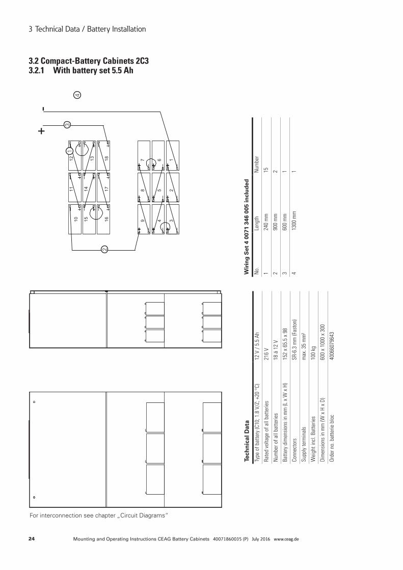
3.2 Compact-Battery Cabinets 2C3 3.2.1 With battery set 5.5 Ah
For interconnection see chapter „Circuit Diagrams“
1
2
3
4
Tech
nic
al D
ata
Type
of b
atte
ry (C
10; 1
.8 V
/Z; +
20 °
C)12
V /
5.5
Ah
Rate
d vo
ltage
of a
ll ba
tterie
s21
6 V
Num
ber o
f all
batte
ries
18 á
12
V
Batte
ry d
imen
sion
s in
mm
(L x
W x
H)
152
x 65
.5 x
98
Conn
ecto
rsSR
-6.3
mm
(Fas
ton)
Supp
ly te
rmin
als
max
. 35
mm
²
Wei
ght i
ncl.
Batte
ries
100
kg
Dim
ensi
ons
in m
m (W
x H
x D
)60
0 x
1000
x 3
00
Orde
r no.
bat
terie
blo
c40
0660
7964
3
Wir
ing
Set
4 0
071
346
005
incl
ud
ed
No.
Leng
thN
umbe
r
124
0 m
m15
290
0 m
m2
360
0 m
m1
413
00 m
m1
25Mounting and Operating Instructions CEAG Battery Cabinets 40071860035 (P) July 2016 www.ceag.de
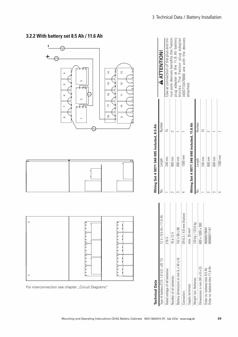
3 Technical Data / Battery Installation
For interconnection see chapter „Circuit Diagrams“
3.2.2 With battery set 8.5 Ah / 11.6 Ah
12
3
4
Tech
nic
al D
ata
Type
of b
atte
ry (C
10; 1
.8 V
/Z; +
20 °
C)12
V /
8.5
Ah /
11.6
Ah
Rate
d vo
ltage
of a
ll ba
tterie
s21
6 V
Num
ber o
f all
batte
ries
18 á
12
V
Batte
ry d
imen
sion
s in
mm
(L x
W x
H)
152
x 98
x 9
8
Conn
ecto
rsSR
-6.3
/ 4.
8 m
m (F
asto
n)
Supp
ly te
rmin
als
max
. 35
mm
²
Wei
ght i
ncl.
Batte
ries
120
kg /
123.
6 kg
Dim
ensi
ons
in m
m (W
x H
x D
)60
0 x
1000
x 3
00
Orde
r no.
bat
terie
blo
c 8.
5 Ah
Or
der n
o. b
atte
rie b
loc
11.6
Ah
4006
6079
644
4006
6071
147
Wir
ing
Set
4 0
071
346
005
incl
ud
ed, 8
.5 A
h
No.
Leng
thN
umbe
r
124
0 m
m15
290
0 m
m2
360
0 m
m1
413
00 m
m1
Wir
ing
Set
4 0
071
346
048
incl
ud
ed, 1
1.6
Ah
No.
Leng
thN
umbe
r
124
0 m
m15
290
0 m
m2
360
0 m
m1
413
00 m
m1
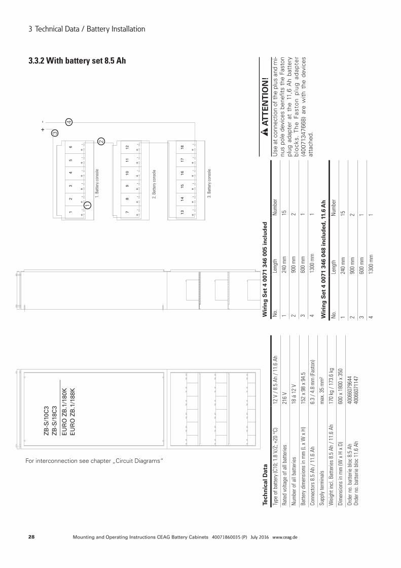
ATT
EN
TIO
N!
Use
at c
onne
ctio
n of
the
plus
and
mi-
nus
pole
dev
ices
ben
efits
the
Fas
ton
plug
ada
pter
at
the
11,6
Ah
batt
ery
blo
cks.
Th
e F
asto
n p
lug
ad
apte
r (4
0071
3476
68)
are
with
the
dev
ices
at
tach
ed.
26 Mounting and Operating Instructions CEAG Battery Cabinets 40071860035 (P) July 2016 www.ceag.de
3 Technical Data / Battery Installation
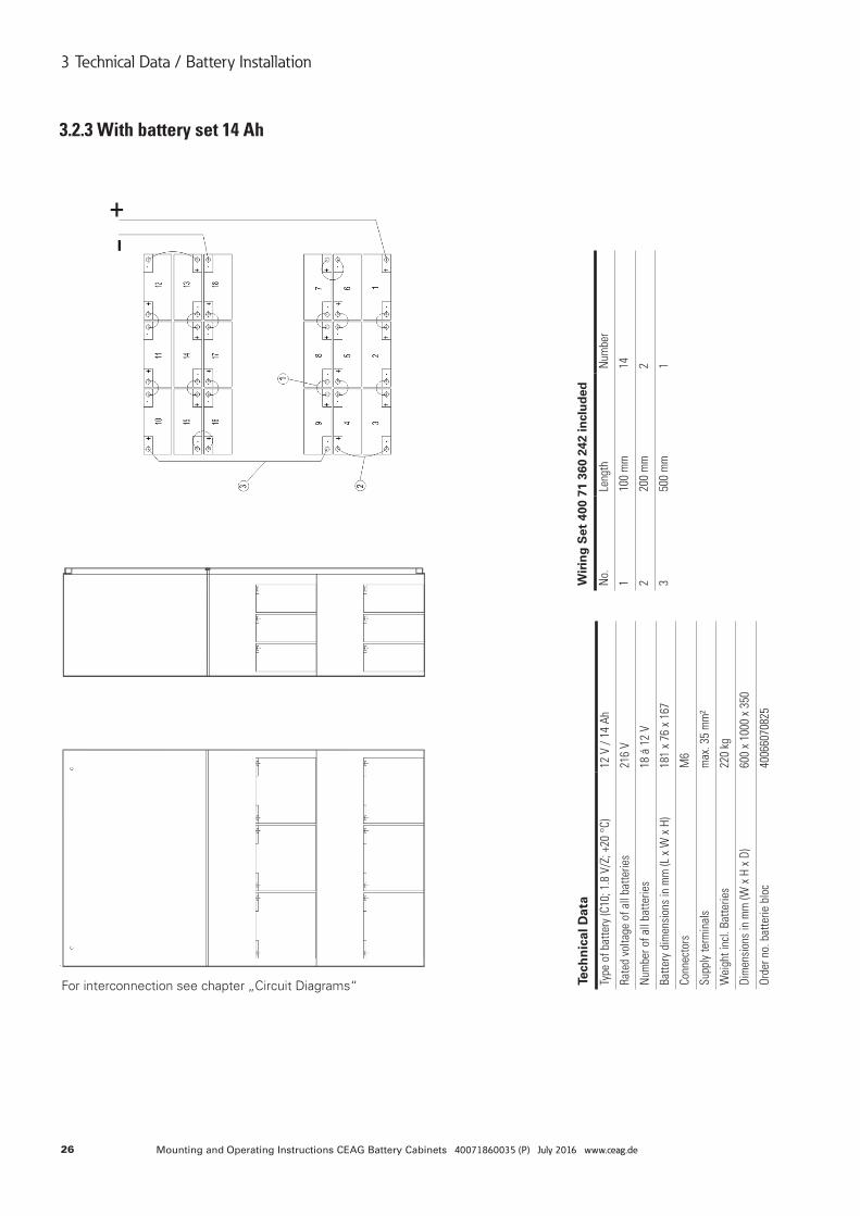
3.2.3 With battery set 14 Ah
For interconnection see chapter „Circuit Diagrams“ Tech
nic
al D
ata
Type
of b
atte
ry (C
10; 1
.8 V
/Z; +
20 °
C)12
V /
14 A
h
Rate
d vo
ltage
of a
ll ba
tterie
s21
6 V
Num
ber o
f all
batte
ries
18 á
12
V
Batte
ry d
imen
sion
s in
mm
(L x
W x
H)
181
x 76
x 1
67
Conn
ecto
rsM
6
Supp
ly te
rmin
als
max
. 35
mm
²
Wei
ght i
ncl.
Batte
ries
220
kg
Dim
ensi
ons
in m
m (W
x H
x D
)60
0 x
1000
x 3
50
Orde
r no.
bat
terie
blo
c40
0660
7082
5
Wir
ing
Set
400
71
360
242
incl
ud
ed
No.
Leng
thN
umbe
r
110
0 m
m14
220
0 m
m2
350
0 m
m1
27Mounting and Operating Instructions CEAG Battery Cabinets 40071860035 (P) July 2016 www.ceag.de
3 Technical Data / Battery Installation
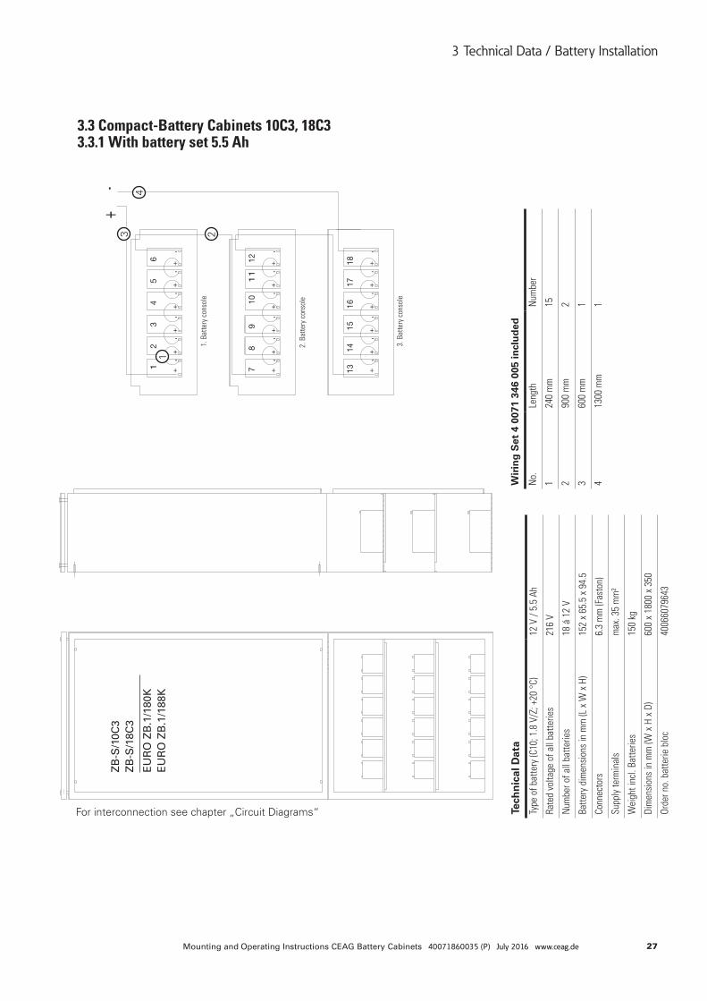
3.3 Compact-Battery Cabinets 10C3, 18C3 3.3.1 With battery set 5.5 Ah
ZB
-S/1
0C3
ZB
-S/1
8C3
EU
RO
ZB
.1/1
80K
EU
RO
ZB
.1/1
88K
For interconnection see chapter „Circuit Diagrams“
1
234
Tech
nic
al D
ata
Type
of b
atte
ry (C
10; 1
.8 V
/Z; +
20 °
C)12
V /
5.5
Ah
Rate
d vo
ltage
of a
ll ba
tterie
s21
6 V
Num
ber o
f all
batte
ries
18 á
12
V
Batte
ry d
imen
sion
s in
mm
(L x
W x
H)
152
x 65
.5 x
94.
5
Conn
ecto
rs6.
3 m
m (F
asto
n)
Supp
ly te
rmin
als
max
. 35
mm
²
Wei
ght i
ncl.
Batte
ries
150
kg
Dim
ensi
ons
in m
m (W
x H
x D
)60
0 x
1800
x 3
50
Orde
r no.
bat
terie
blo
c40
0660
7964
3
Wir
ing
Set
4 0
071
346
005
incl
ud
ed
No.
Leng
thN
umbe
r
124
0 m
m15
290
0 m
m2
360
0 m
m1
413
00 m
m1
1. B
atte
ry c
onso
le
2. B
atte
ry c
onso
le
3. B
atte
ry c
onso
le
28 Mounting and Operating Instructions CEAG Battery Cabinets 40071860035 (P) July 2016 www.ceag.de
3 Technical Data / Battery Installation
3.3.2 With battery set 8.5 Ah
For interconnection see chapter „Circuit Diagrams“
1
2
3
4
Tech
nic
al D
ata
Type
of b
atte
ry (C
10; 1
.8 V
/Z; +
20 °
C)12
V /
8.5
Ah /
11.6
Ah
Rate
d vo
ltage
of a
ll ba
tterie
s21
6 V
Num
ber o
f all
batte
ries
18 á
12
V
Batte
ry d
imen
sion
s in
mm
(L x
W x
H)
152
x 98
x 9
4.5
Conn
ecto
rs 8
.5 A
h / 1
1.6
Ah6.
3 / 4
.8 m
m (F
asto
n)
Supp
ly te
rmin
als
max
. 35
mm
²
Wei
ght i
ncl.
Batte
ries
8.5
Ah /
11.6
Ah
170
kg /
173.
6 kg
Dim
ensi
ons
in m
m (W
x H
x D
)60
0 x
1800
x 3
50
Orde
r no.
bat
terie
blo
c 8.
5 Ah
Or
der n
o. b
atte
rie b
loc
11.6
Ah
4006
6079
644
4006
6071
147
Wir
ing
Set
4 0
071
346
005
incl
ud
ed
No.
Leng
thN
umbe
r
124
0 m
m15
290
0 m
m2
360
0 m
m1
413
00 m
m1
ZB
-S/1
0C3
ZB
-S/1
8C3
EU
RO
ZB
.1/1
80K
EU
RO
ZB
.1/1
88K
1. B
atte
ry c
onso
le
2. B
atte
ry c
onso
le
3. B
atte
ry c
onso
le
Wir
ing
Set
4 0
071
346
048
incl
ud
ed, 1
1.6
Ah
No.
Leng
thN
umbe
r
124
0 m
m15
290
0 m
m2
360
0 m
m1
413
00 m
m1
ATT
EN
TIO
N!
Use
at c
onne
ctio
n of
the
plus
and
mi-
nus
pole
dev
ices
ben
efits
the
Fas
ton
plug
ada
pter
at
the
11,6
Ah
batt
ery
blo
cks.
Th
e F
asto
n p
lug
ad
apte
r (4
0071
3476
68)
are
with
the
dev
ices
at
tach
ed.
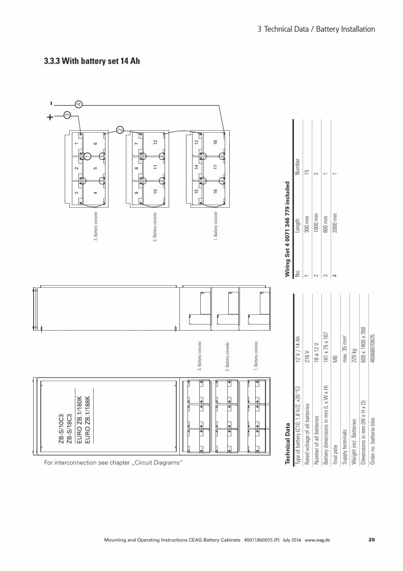
29Mounting and Operating Instructions CEAG Battery Cabinets 40071860035 (P) July 2016 www.ceag.de
3 Technical Data / Battery Installation
3.3.3 With battery set 14 Ah
For interconnection see chapter „Circuit Diagrams“
ZB
-S/1
0C3
ZB
-S/1
8C3
EU
RO
ZB
.1/1
80K
EU
RO
ZB
.1/1
88K
1
2
3
4
Tech
nic
al D
ata
Type
of b
atte
ry (C
10; 1
.8 V
/Z; +
20 °
C)12
V /
14 A
h
Rate
d vo
ltage
of a
ll ba
tterie
s21
6 V
Num
ber o
f all
batte
ries
18 á
12
V
Batte
ry d
imen
sion
s in
mm
(L x
W x
H)
181
x 75
x 1
67
final
pol
eM
6
Supp
ly te
rmin
als
max
. 35
mm
²
Wei
ght i
ncl.
Batte
ries
220
kg
Dim
ensi
ons
in m
m (W
x H
x D
)60
0 x
1800
x 3
50
Orde
r no.
bat
terie
blo
c40
0660
7082
5
Wir
ing
Set
4 0
071
346
779
incl
ud
ed
No.
Leng
thN
umbe
r
130
0 m
m15
210
00 m
m2
380
0 m
m1
420
00 m
m1
1. B
atte
ry c
onso
le
1. B
atte
ry c
onso
le
2. B
atte
ry c
onso
le
2. B
atte
ry c
onso
le
3. B
atte
ry c
onso
le
3. B
atte
ry c
onso
le
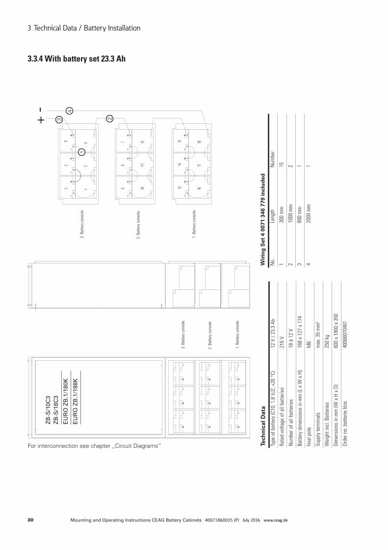
30 Mounting and Operating Instructions CEAG Battery Cabinets 40071860035 (P) July 2016 www.ceag.de
3 Technical Data / Battery Installation
3.3.4 With battery set 23.3 Ah
For interconnection see chapter „Circuit Diagrams“
ZB
-S/1
0C3
ZB
-S/1
8C3
EU
RO
ZB
.1/1
80K
EU
RO
ZB
.1/1
88K
1
23
4
Tech
nic
al D
ata
Type
of b
atte
ry (C
10; 1
.8 V
/Z; +
20 °
C)12
V /
23.3
Ah
Rate
d vo
ltage
of a
ll ba
tterie
s21
6 V
Num
ber o
f all
batte
ries
18 á
12
V
Batte
ry d
imen
sion
s in
mm
(L x
W x
H)
168
x 12
7 x
174
final
pol
eM
6
Supp
ly te
rmin
als
max
. 35
mm
²
Wei
ght i
ncl.
Batte
ries
250
kg
Dim
ensi
ons
in m
m (W
x H
x D
)60
0 x
1800
x 3
50
Orde
r no.
bat
terie
blo
c40
0660
7046
1
Wir
ing
Set
4 0
071
346
779
incl
ud
ed
No.
Leng
thN
umbe
r
130
0 m
m15
210
00 m
m2
380
0 m
m1
420
00 m
m1
1. B
atte
ry c
onso
le
1. B
atte
ry c
onso
le
2. B
atte
ry c
onso
le
2. B
atte
ry c
onso
le
3. B
atte
ry c
onso
le
3. B
atte
ry c
onso
le
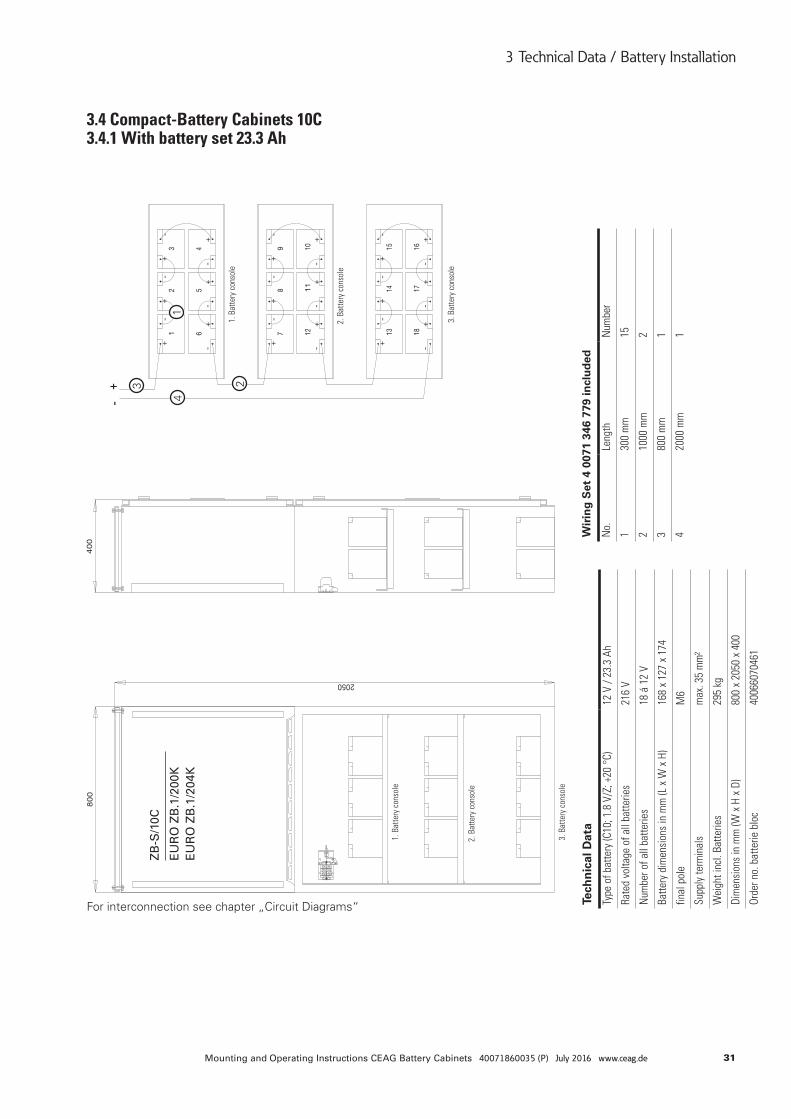
31Mounting and Operating Instructions CEAG Battery Cabinets 40071860035 (P) July 2016 www.ceag.de
3 Technical Data / Battery Installation
For interconnection see chapter „Circuit Diagrams“
ZB
-S/1
0C
EU
RO
ZB
.1/2
00K
EU
RO
ZB
.1/2
04K
3.4 Compact-Battery Cabinets 10C 3.4.1 With battery set 23.3 Ah
1
23
4
Tech
nic
al D
ata
Type
of b
atte
ry (C
10; 1
.8 V
/Z; +
20 °
C)12
V /
23.3
Ah
Rate
d vo
ltage
of a
ll ba
tterie
s21
6 V
Num
ber o
f all
batte
ries
18 á
12
V
Batte
ry d
imen
sion
s in
mm
(L x
W x
H)
168
x 12
7 x
174
final
pol
eM
6
Supp
ly te
rmin
als
max
. 35
mm
²
Wei
ght i
ncl.
Batte
ries
295
kg
Dim
ensi
ons
in m
m (W
x H
x D
)80
0 x
2050
x 4
00
Orde
r no.
bat
terie
blo
c40
0660
7046
1
Wir
ing
Set
4 0
071
346
779
incl
ud
ed
No.
Leng
thN
umbe
r
130
0 m
m15
210
00 m
m2
380
0 m
m1
420
00 m
m1
3. B
atte
ry c
onso
le
3. B
atte
ry c
onso
le
2. B
atte
ry c
onso
le
2. B
atte
ry c
onso
le
1. B
atte
ry c
onso
le
1. B
atte
ry c
onso
le
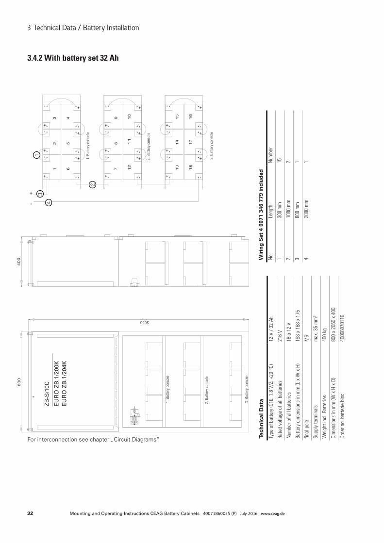
32 Mounting and Operating Instructions CEAG Battery Cabinets 40071860035 (P) July 2016 www.ceag.de
3 Technical Data / Battery Installation
3.4.2 With battery set 32 Ah
For interconnection see chapter „Circuit Diagrams“
ZB
-S/1
0C
EU
RO
ZB
.1/2
00K
EU
RO
ZB
.1/2
04K
1
2
3
4
Tech
nic
al D
ata
Type
of b
atte
ry (C
10; 1
.8 V
/Z; +
20 °
C)12
V /
32 A
h
Rate
d vo
ltage
of a
ll ba
tterie
s21
6 V
Num
ber o
f all
batte
ries
18 á
12
V
Batte
ry d
imen
sion
s in
mm
(L x
W x
H)
198
x 16
8 x
175
final
pol
eM
6
Supp
ly te
rmin
als
max
. 35
mm
²
Wei
ght i
ncl.
Batte
ries
400
kg
Dim
ensi
ons
in m
m (W
x H
x D
)80
0 x
2050
x 4
00
Orde
r no.
bat
terie
blo
c40
0660
7011
6
Wir
ing
Set
4 0
071
346
779
incl
ud
ed
No.
Leng
thN
umbe
r
130
0 m
m15
210
00 m
m2
380
0 m
m1
420
00 m
m1
3. B
atte
ry c
onso
le
3. B
atte
ry c
onso
le2.
Bat
tery
con
sole
2. B
atte
ry c
onso
le
1. B
atte
ry c
onso
le
1. B
atte
ry c
onso
le
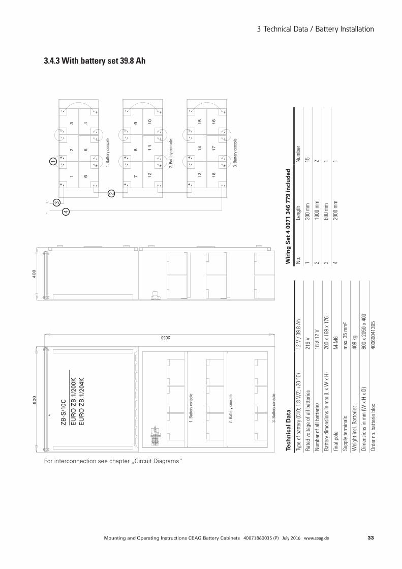
33Mounting and Operating Instructions CEAG Battery Cabinets 40071860035 (P) July 2016 www.ceag.de
3 Technical Data / Battery Installation
ZB
-S/1
0C
EU
RO
ZB
.1/2
00K
EU
RO
ZB
.1/2
04K
3.4.3 With battery set 39.8 Ah
For interconnection see chapter „Circuit Diagrams“
1
2
3
4
Tech
nic
al D
ata
Type
of b
atte
ry (C
10; 1
.8 V
/Z; +
20 °
C)12
V /
39.8
Ah
Rate
d vo
ltage
of a
ll ba
tterie
s21
6 V
Num
ber o
f all
batte
ries
18 á
12
V
Batte
ry d
imen
sion
s in
mm
(L x
W x
H)
200
x 16
9 x
176
final
pol
eM
-M6
Supp
ly te
rmin
als
max
. 35
mm
²
Wei
ght i
ncl.
Batte
ries
409
kg
Dim
ensi
ons
in m
m (W
x H
x D
)80
0 x
2050
x 4
00
Orde
r no.
bat
terie
blo
c40
0660
4139
5
Wir
ing
Set
4 0
071
346
779
incl
ud
ed
No.
Leng
thN
umbe
r
130
0 m
m15
210
00 m
m2
380
0 m
m1
420
00 m
m1
3. B
atte
ry c
onso
le
3. B
atte
ry c
onso
le2.
Bat
tery
con
sole
2. B
atte
ry c
onso
le
1. B
atte
ry c
onso
le
1. B
atte
ry c
onso
le
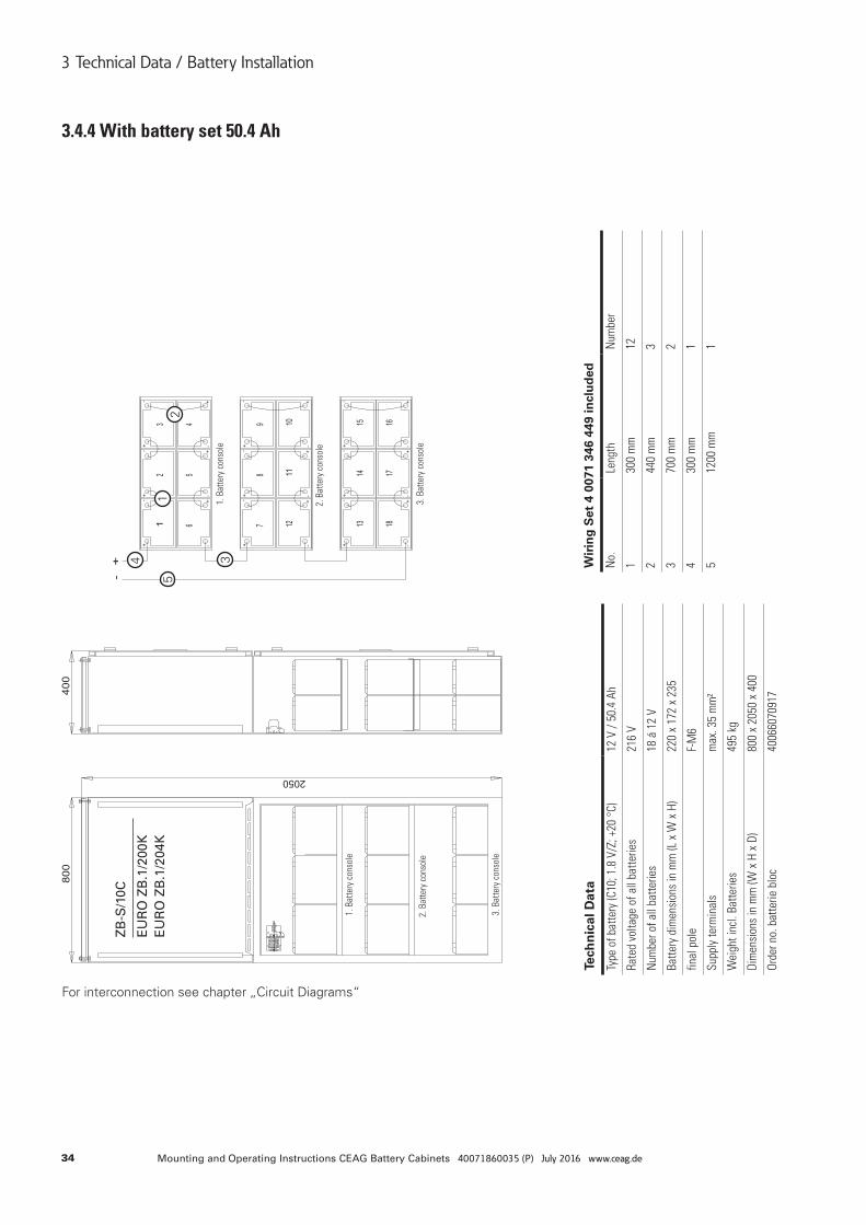
34 Mounting and Operating Instructions CEAG Battery Cabinets 40071860035 (P) July 2016 www.ceag.de
3 Technical Data / Battery Installation
3.4.4 With battery set 50.4 Ah
For interconnection see chapter „Circuit Diagrams“
ZB
-S/1
0C
EU
RO
ZB
.1/2
00K
EU
RO
ZB
.1/2
04K
12
34
5
Tech
nic
al D
ata
Type
of b
atte
ry (C
10; 1
.8 V
/Z; +
20 °
C)12
V /
50.4
Ah
Rate
d vo
ltage
of a
ll ba
tterie
s21
6 V
Num
ber o
f all
batte
ries
18 á
12
V
Batte
ry d
imen
sion
s in
mm
(L x
W x
H)
220
x 17
2 x
235
final
pol
eF-
M6
Supp
ly te
rmin
als
max
. 35
mm
²
Wei
ght i
ncl.
Batte
ries
495
kg
Dim
ensi
ons
in m
m (W
x H
x D
)80
0 x
2050
x 4
00
Orde
r no.
bat
terie
blo
c40
0660
7091
7
Wir
ing
Set
4 0
071
346
449
incl
ud
ed
No.
Leng
thN
umbe
r
130
0 m
m12
244
0 m
m3
370
0 m
m2
430
0 m
m1
512
00 m
m1
3. B
atte
ry c
onso
le
3. B
atte
ry c
onso
le2.
Bat
tery
con
sole
2. B
atte
ry c
onso
le
1. B
atte
ry c
onso
le
1. B
atte
ry c
onso
le
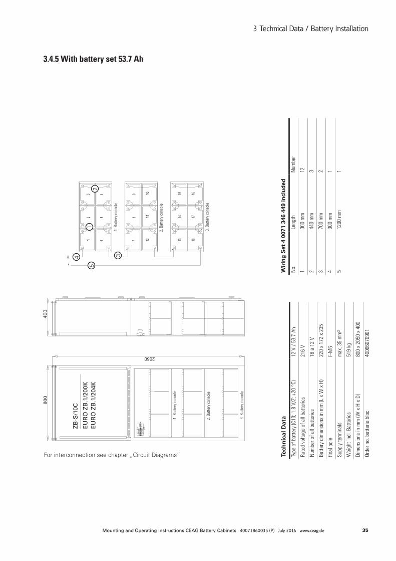
35Mounting and Operating Instructions CEAG Battery Cabinets 40071860035 (P) July 2016 www.ceag.de
3 Technical Data / Battery Installation
3. B
atte
ry c
onso
le
3. B
atte
ry c
onso
le2.
Bat
tery
con
sole
2. B
atte
ry c
onso
le
1. B
atte
ry c
onso
le
1. B
atte
ry c
onso
le
3.4.5 With battery set 53.7 Ah
For interconnection see chapter „Circuit Diagrams“
ZB
-S/1
0C
EU
RO
ZB
.1/2
00K
EU
RO
ZB
.1/2
04K
12
34
5
Tech
nic
al D
ata
Type
of b
atte
ry (C
10; 1
.8 V
/Z; +
20 °
C)12
V /
53.7
Ah
Rate
d vo
ltage
of a
ll ba
tterie
s21
6 V
Num
ber o
f all
batte
ries
18 á
12
V
Batte
ry d
imen
sion
s in
mm
(L x
W x
H)
220
x 17
2 x
235
final
pol
eF-
M6
Supp
ly te
rmin
als
max
. 35
mm
²
Wei
ght i
ncl.
Batte
ries
519
kg
Dim
ensi
ons
in m
m (W
x H
x D
)80
0 x
2050
x 4
00
Orde
r no.
bat
terie
blo
c40
0660
7090
1
Wir
ing
Set
4 0
071
346
449
incl
ud
ed
No.
Leng
thN
umbe
r
130
0 m
m12
244
0 m
m3
370
0 m
m2
430
0 m
m1
512
00 m
m1
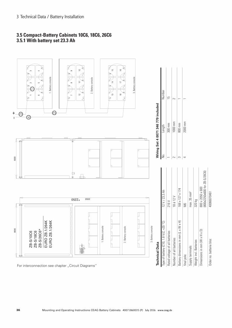
36 Mounting and Operating Instructions CEAG Battery Cabinets 40071860035 (P) July 2016 www.ceag.de
3 Technical Data / Battery Installation
For interconnection see chapter „Circuit Diagrams“
ZB
-S/1
0C6
ZB
-S/1
8C6
ZB
-S/2
6C6*
EU
RO
ZB
.1/2
64K
EU
RO
ZB
.1/2
64K
*2250
3.5 Compact-Battery Cabinets 10C6, 18C6, 26C6 3.5.1 With battery set 23.3 Ah
1
23
4
Tech
nic
al D
ata
Type
of b
atte
ry (C
10; 1
.8 V
/Z; +
20 °
C)12
V /
23.3
Ah
Rate
d vo
ltage
of a
ll ba
tterie
s21
6 V
Num
ber o
f all
batte
ries
18 á
12
V
Batte
ry d
imen
sion
s in
mm
(L x
W x
H)
168
x 12
7 x
174
final
pol
eM
6
Supp
ly te
rmin
als
max
. 35
mm
²
Wei
ght i
ncl.
Batte
ries
320
kg
Dim
ensi
ons
in m
m (W
x H
x D
)80
0 x
2050
x 6
00
(800
x225
0x60
0 fo
r ZB-
S/26
C6)
Orde
r no.
bat
terie
blo
c40
0660
7046
1
Wir
ing
Set
4 0
071
346
779
incl
ud
ed
No.
Leng
thN
umbe
r
130
0 m
m15
210
00 m
m2
380
0 m
m1
420
00 m
m1
3. B
atte
ry c
onso
le
3. B
atte
ry c
onso
le
2. B
atte
ry c
onso
le
2. B
atte
ry c
onso
le
1. B
atte
ry c
onso
le
1. B
atte
ry c
onso
le
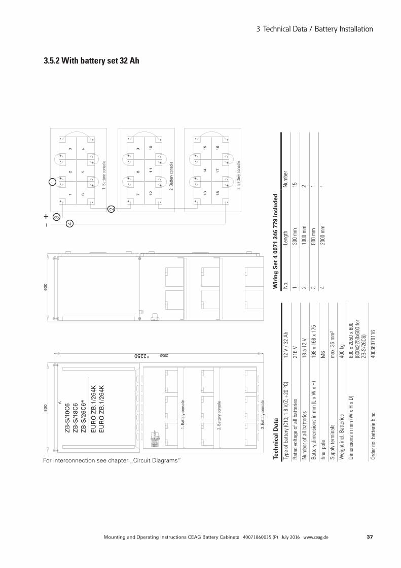
37Mounting and Operating Instructions CEAG Battery Cabinets 40071860035 (P) July 2016 www.ceag.de
3 Technical Data / Battery Installation
3.5.2 With battery set 32 AhZ
B-S
/10C
6 Z
B-S
/18C
6 Z
B-S
/26C
6*
EU
RO
ZB
.1/2
64K
EU
RO
ZB
.1/2
64K
*2250
1
2
3
4
For interconnection see chapter „Circuit Diagrams“ Tech
nic
al D
ata
Type
of b
atte
ry (C
10; 1
.8 V
/Z; +
20 °
C)12
V /
32 A
h
Rate
d vo
ltage
of a
ll ba
tterie
s21
6 V
Num
ber o
f all
batte
ries
18 á
12
V
Batte
ry d
imen
sion
s in
mm
(L x
W x
H)
198
x 16
8 x
175
final
pol
eM
6
Supp
ly te
rmin
als
max
. 35
mm
²
Wei
ght i
ncl.
Batte
ries
400
kg
Dim
ensi
ons
in m
m (W
x H
x D
)80
0 x
2050
x 6
00
(800
x225
0x60
0 fo
r ZB
-S/2
6C6)
Orde
r no.
bat
terie
blo
c40
0660
7011
6
Wir
ing
Set
4 0
071
346
779
incl
ud
ed
No.
Leng
thN
umbe
r
130
0 m
m15
210
00 m
m2
380
0 m
m1
420
00 m
m1
3. B
atte
ry c
onso
le
3. B
atte
ry c
onso
le
2. B
atte
ry c
onso
le
2. B
atte
ry c
onso
le
1. B
atte
ry c
onso
le
1. B
atte
ry c
onso
le
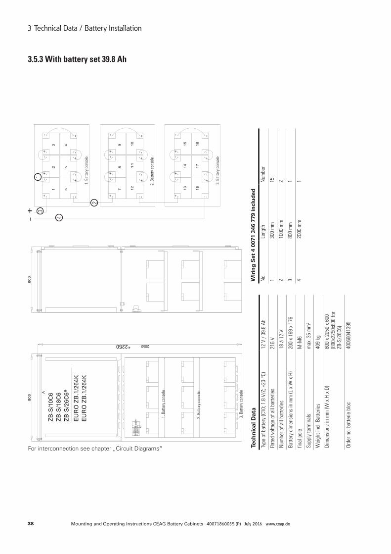
38 Mounting and Operating Instructions CEAG Battery Cabinets 40071860035 (P) July 2016 www.ceag.de
3 Technical Data / Battery Installation
3. B
atte
ry c
onso
le
3. B
atte
ry c
onso
le
2. B
atte
ry c
onso
le
2. B
atte
ry c
onso
le
1. B
atte
ry c
onso
le
1. B
atte
ry c
onso
le
3.5.3 With battery set 39.8 Ah
For interconnection see chapter „Circuit Diagrams“
ZB
-S/1
0C6
ZB
-S/1
8C6
ZB
-S/2
6C6*
EU
RO
ZB
.1/2
64K
EU
RO
ZB
.1/2
64K
*2250
1
2
3
4
Tech
nic
al D
ata
Type
of b
atte
ry (C
10; 1
.8 V
/Z; +
20 °
C)12
V /
39.8
Ah
Rate
d vo
ltage
of a
ll ba
tterie
s21
6 V
Num
ber o
f all
batte
ries
18 á
12
V
Batte
ry d
imen
sion
s in
mm
(L x
W x
H)
200
x 16
9 x
176
final
pol
eM
-M6
Supp
ly te
rmin
als
max
. 35
mm
²
Wei
ght i
ncl.
Batte
ries
409
kg
Dim
ensi
ons
in m
m (W
x H
x D
)80
0 x
2050
x 6
00
(800
x225
0x60
0 fo
r ZB
-S/2
6C6)
Orde
r no.
bat
terie
blo
c40
0660
4139
5
Wir
ing
Set
4 0
071
346
779
incl
ud
ed
No.
Leng
thN
umbe
r
130
0 m
m15
210
00 m
m2
380
0 m
m1
420
00 m
m1
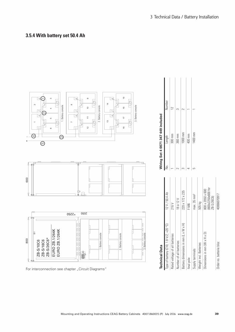
39Mounting and Operating Instructions CEAG Battery Cabinets 40071860035 (P) July 2016 www.ceag.de
3 Technical Data / Battery Installation
3. B
atte
ry c
onso
le
3. B
atte
ry c
onso
le
2. B
atte
ry c
onso
le
2. B
atte
ry c
onso
le1.
Bat
tery
con
sole
1. B
atte
ry c
onso
le
3.5.4 With battery set 50.4 Ah
For interconnection see chapter „Circuit Diagrams“
ZB
-S/1
0C6
ZB
-S/1
8C6
ZB
-S/2
6C6*
EU
RO
ZB
.1/2
64K
EU
RO
ZB
.1/2
64K
*2250
12
34
5
Tech
nic
al D
ata
Type
of b
atte
ry (C
10; 1
.8 V
/Z; +
20 °
C)12
V /
50.4
Ah
Rate
d vo
ltage
of a
ll ba
tterie
s21
6 V
Num
ber o
f all
batte
ries
18 á
12
V
Batte
ry d
imen
sion
s in
mm
(L x
W x
H)
220
x 17
2 x
235
final
pol
eF-
M6
Supp
ly te
rmin
als
max
. 35
mm
²
Wei
ght i
ncl.
Batte
ries
505
kg
Dim
ensi
ons
in m
m (W
x H
x D
)80
0 x
2050
x 6
00
(800
x225
0x60
0 fo
r ZB
-S/2
6C6)
Orde
r no.
bat
terie
blo
c40
0660
7091
7
Wir
ing
Set
4 0
071
347
449
incl
ud
ed
No.
Leng
thN
umbe
r
130
0 m
m12
236
0 m
m3
310
00 m
m2
440
0 m
m1
514
00 m
m1
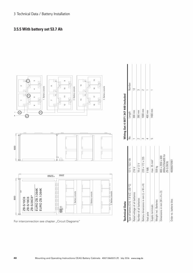
40 Mounting and Operating Instructions CEAG Battery Cabinets 40071860035 (P) July 2016 www.ceag.de
3 Technical Data / Battery Installation
3. B
atte
ry c
onso
le
3. B
atte
ry c
onso
le
2. B
atte
ry c
onso
le
2. B
atte
ry c
onso
le1.
Bat
tery
con
sole
1. B
atte
ry c
onso
le
3.5.5 With battery set 53.7 Ah
For interconnection see chapter „Circuit Diagrams“
*2250
ZB
-S/1
0C6
ZB
-S/1
8C6
ZB
-S/2
6C6*
EU
RO
ZB
.1/2
64K
EU
RO
ZB
.1/2
64K
12
34
5
Tech
nic
al D
ata
Type
of b
atte
ry (C
10; 1
.8 V
/Z; +
20 °
C)12
V /
53.7
Ah
Rate
d vo
ltage
of a
ll ba
tterie
s21
6 V
Num
ber o
f all
batte
ries
18 á
12
V
Batte
ry d
imen
sion
s in
mm
(L x
W x
H)
220
x 17
2 x
235
final
pol
eF-
M6
Supp
ly te
rmin
als
max
. 35
mm
²
Wei
ght i
ncl.
Batte
ries
559
kg
Dim
ensi
ons
in m
m (W
x H
x D
)80
0 x
2050
x 6
00
(800
x225
0x60
0 fo
r ZB
-S/2
6C6)
Orde
r no.
bat
terie
blo
c40
0660
7090
1
Wir
ing
Set
4 0
071
347
449
incl
ud
ed
No.
Leng
thN
umbe
r
130
0 m
m12
236
0 m
m3
310
00 m
m2
440
0 m
m1
514
00 m
m1
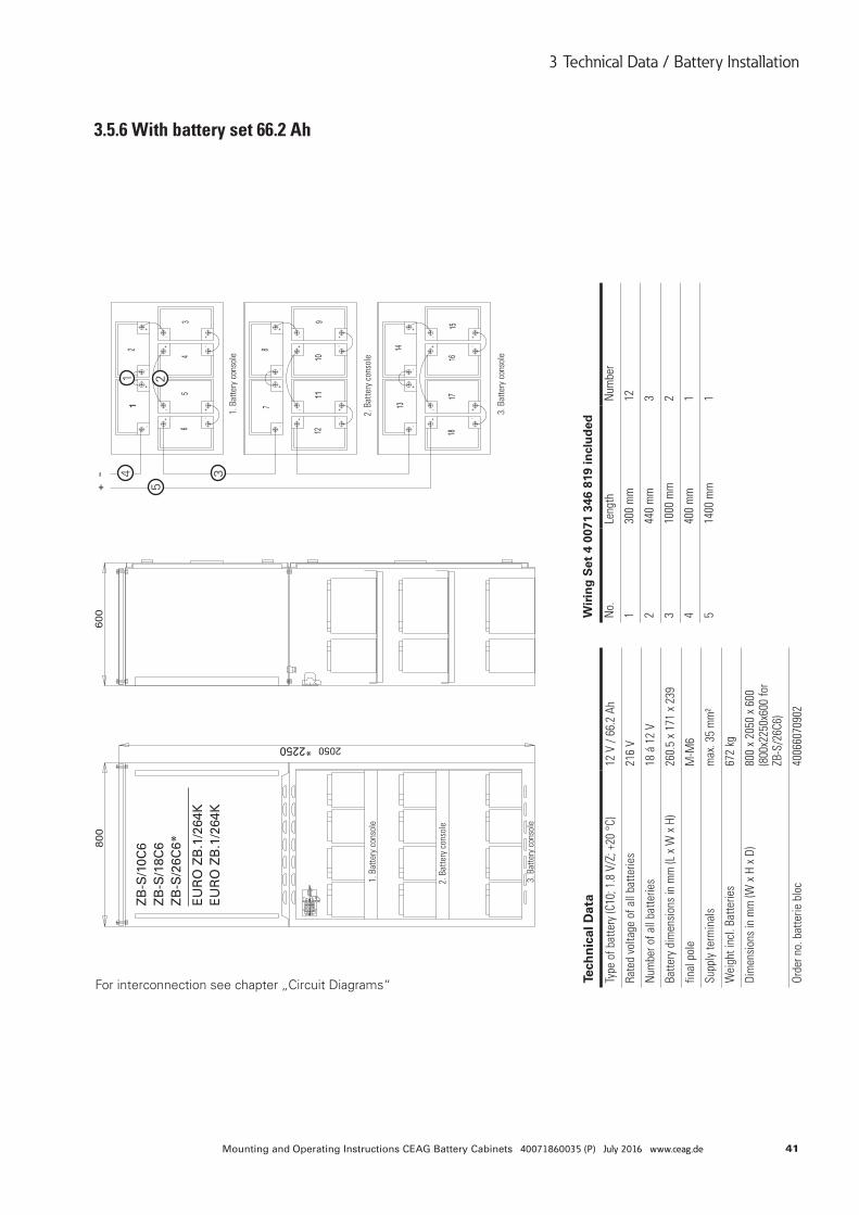
41Mounting and Operating Instructions CEAG Battery Cabinets 40071860035 (P) July 2016 www.ceag.de
3 Technical Data / Battery Installation
3. B
atte
ry c
onso
le
3. B
atte
ry c
onso
le
2. B
atte
ry c
onso
le
2. B
atte
ry c
onso
le1.
Bat
tery
con
sole
1. B
atte
ry c
onso
le
3.5.6 With battery set 66.2 Ah
For interconnection see chapter „Circuit Diagrams“
*2250
ZB
-S/1
0C6
ZB
-S/1
8C6
ZB
-S/2
6C6*
EU
RO
ZB
.1/2
64K
EU
RO
ZB
.1/2
64K
1 2
34
5
Tech
nic
al D
ata
Type
of b
atte
ry (C
10; 1
.8 V
/Z; +
20 °
C)12
V /
66.2
Ah
Rate
d vo
ltage
of a
ll ba
tterie
s21
6 V
Num
ber o
f all
batte
ries
18 á
12
V
Batte
ry d
imen
sion
s in
mm
(L x
W x
H)
260.
5 x
171
x 23
9
final
pol
eM
-M6
Supp
ly te
rmin
als
max
. 35
mm
²
Wei
ght i
ncl.
Batte
ries
672
kg
Dim
ensi
ons
in m
m (W
x H
x D
)80
0 x
2050
x 6
00
(800
x225
0x60
0 fo
r ZB
-S/2
6C6)
Orde
r no.
bat
terie
blo
c40
0660
7090
2
Wir
ing
Set
4 0
071
346
819
incl
ud
ed
No.
Leng
thN
umbe
r
130
0 m
m12
244
0 m
m3
310
00 m
m2
440
0 m
m1
514
00 m
m1
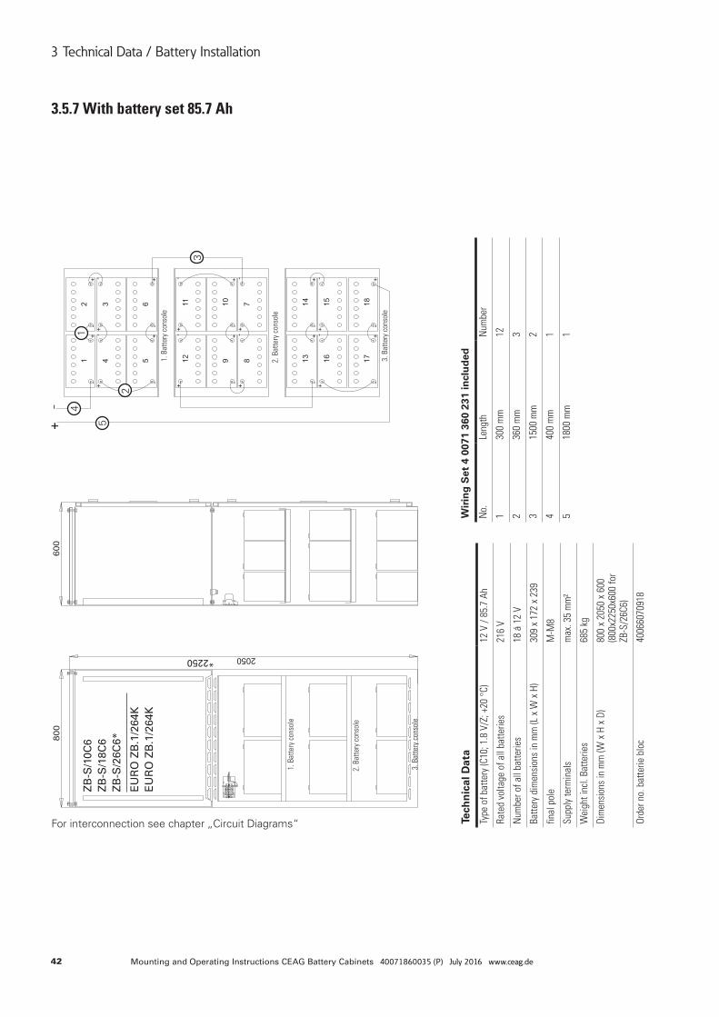
42 Mounting and Operating Instructions CEAG Battery Cabinets 40071860035 (P) July 2016 www.ceag.de
3 Technical Data / Battery Installation
3.5.7 With battery set 85.7 Ah
For interconnection see chapter „Circuit Diagrams“
*2250
ZB
-S/1
0C6
ZB
-S/1
8C6
ZB
-S/2
6C6*
EU
RO
ZB
.1/2
64K
EU
RO
ZB
.1/2
64K
1
2
3
4
5
Tech
nic
al D
ata
Type
of b
atte
ry (C
10; 1
.8 V
/Z; +
20 °
C)12
V /
85.7
Ah
Rate
d vo
ltage
of a
ll ba
tterie
s21
6 V
Num
ber o
f all
batte
ries
18 á
12
V
Batte
ry d
imen
sion
s in
mm
(L x
W x
H)
309
x 17
2 x
239
final
pol
eM
-M8
Supp
ly te
rmin
als
max
. 35
mm
²
Wei
ght i
ncl.
Batte
ries
685
kg
Dim
ensi
ons
in m
m (W
x H
x D
)80
0 x
2050
x 6
00
(800
x225
0x60
0 fo
r ZB
-S/2
6C6)
Orde
r no.
bat
terie
blo
c40
0660
7091
8
Wir
ing
Set
4 0
071
360
231
incl
ud
ed
No.
Leng
thN
umbe
r
130
0 m
m12
236
0 m
m3
315
00 m
m2
440
0 m
m1
518
00 m
m1
3. B
atte
ry c
onso
le
3. B
atte
ry c
onso
le
2. B
atte
ry c
onso
le
2. B
atte
ry c
onso
le
1. B
atte
ry c
onso
le
1. B
atte
ry c
onso
le
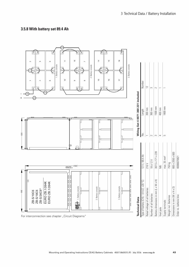
43Mounting and Operating Instructions CEAG Battery Cabinets 40071860035 (P) July 2016 www.ceag.de
3 Technical Data / Battery Installation
3.5.8 With battery set 89.4 Ah
For interconnection see chapter „Circuit Diagrams“
ZB
-S/1
0C6
ZB
-S/1
8C6
ZB
-S/2
6C6*
EU
RO
ZB
.1/2
64K
EU
RO
ZB
.1/2
64K
*2250
1
2
3
4
5
Tech
nic
al D
ata
Type
of b
atte
ry (C
10; 1
.8 V
/Z; +
20 °
C)12
V /
89.4
Ah
Rate
d vo
ltage
of a
ll ba
tterie
s21
6 V
Num
ber o
f all
batte
ries
18 á
12
V
Batte
ry d
imen
sion
s in
mm
(L x
W x
H)
307.
5 x
171
x 23
9
final
pol
eM
6
Supp
ly te
rmin
als
max
. 35
mm
²
Wei
ght i
ncl.
Batte
ries
750
kg
Dim
ensi
ons
in m
m (W
x H
x D
)80
0 x
2050
x 6
00
Orde
r no.
bat
terie
blo
c40
0660
7082
1
Wir
ing
Set
4 0
071
360
231
incl
ud
ed
No.
Leng
thN
umbe
r
130
0 m
m12
236
0 m
m3
315
00 m
m2
440
0 m
m1
518
00 m
m1
3. B
atte
ry c
onso
le
3. B
atte
ry c
onso
le
2. B
atte
ry c
onso
le
2. B
atte
ry c
onso
le
1. B
atte
ry c
onso
le
1. B
atte
ry c
onso
le
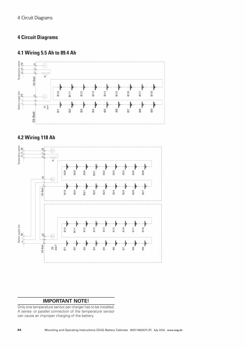
44 Mounting and Operating Instructions CEAG Battery Cabinets 40071860035 (P) July 2016 www.ceag.de
4 Circuit Diagrams
4 Circuit Diagrams
4.1 Wiring 5.5 Ah to 89.4 Ah
4.2 Wiring 118 Ah
IMPORTANT NOTE!Only one temperature sensor per charger has to be installed. A series- or parallel connection of the temperature sensor can cause an improper charging of the battery.
Batte
ry s
uppl
y lin
eBa
ttery
sup
ply
line
Tem
pera
ture
sen
sor
Tem
pera
ture
sen
sor
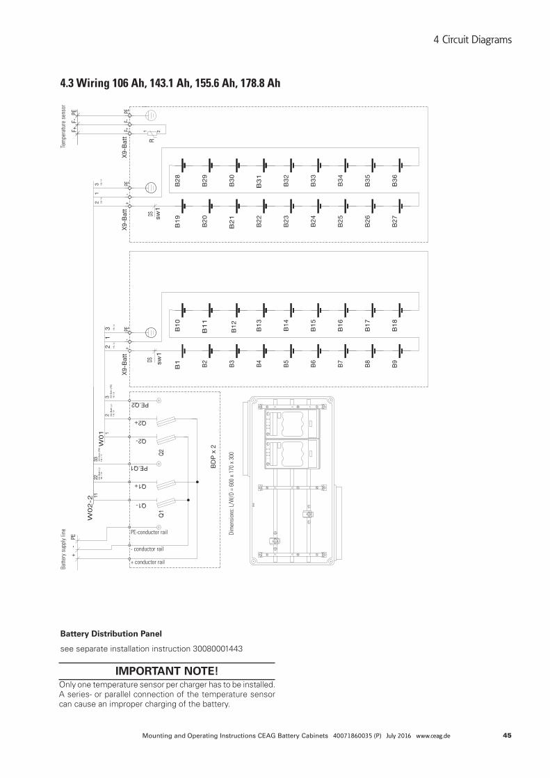
45Mounting and Operating Instructions CEAG Battery Cabinets 40071860035 (P) July 2016 www.ceag.de
4 Circuit Diagrams
4.3 Wiring 106 Ah, 143.1 Ah, 155.6 Ah, 178.8 Ah
Battery Distribution Panel
see separate installation instruction 30080001443
IMPORTANT NOTE!Only one temperature sensor per charger has to be installed. A series- or parallel connection of the temperature sensor can cause an improper charging of the battery.
Batte
ry s
uppl
y lin
e
Dim
ensi
ons:
L/W
/D =
600
x 1
70 x
300
PE-conductor rail
- conductor rail
+ conductor rail
Tem
pera
ture
sen
sor
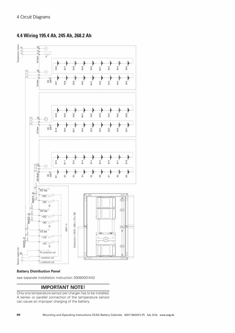
46 Mounting and Operating Instructions CEAG Battery Cabinets 40071860035 (P) July 2016 www.ceag.de
4 Circuit Diagrams
4.4 Wiring 195.4 Ah, 245 Ah, 268.2 Ah
Battery Distribution Panel
see separate installation instruction 30080001443
IMPORTANT NOTE!Only one temperature sensor per charger has to be installed. A series- or parallel connection of the temperature sensor can cause an improper charging of the battery.
Batte
ry s
uppl
y lin
eTe
mpe
ratu
re s
enso
r
Dim
ensi
ons:
L/W
/D =
600
x 1
70 x
300
PE-conductor rail
- conductor rail
+ conductor rail
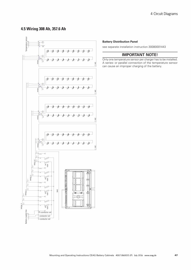
47Mounting and Operating Instructions CEAG Battery Cabinets 40071860035 (P) July 2016 www.ceag.de
4 Circuit Diagrams
4.5 Wiring 308 Ah, 357.6 Ah
Battery Distribution Panel
see separate installation instruction 30080001443
IMPORTANT NOTE!Only one temperature sensor per charger has to be installed. A series- or parallel connection of the temperature sensor can cause an improper charging of the battery.
Batte
ry s
uppl
y lin
eTe
mpe
ratu
re s
enso
r
Dim
ensi
ons:
L/W
/D =
900
x 1
70 x
300
PE-conductor rail
- conductor rail
+ conductor rail
48 Mounting and Operating Instructions CEAG Battery Cabinets 40071860035 (P) July 2016 www.ceag.de
5 Transport, Packaging and Storage
5 Transport, Packaging and Storage
5.1 Safety Notes
WARNING! RISK OF INJURY!There is a risk of injury when transporting or loading due to falling parts.
ATTENTION! DAMAGE TO PROPERTY!
Batteries will be destroyed or damaged by improper trans-port.
• The following safety notes have to be observed:• Never lift loads over person`s head.• Always move battery with great care and attention.• Only use lifting accessories and hoisting devices with
enough loading capacity.
5.2 Carriage by land of closed lead acid batteriesMonoblocs have to be transported standing upright.
Batteries with no damage do not have to be transported as hazardous material (In Germany according to ”Hazardous Material Regulation for Street –ADR- and for Train –RID-“).
They have to be protected against short circuits, slipping, falling and damage.
Blocs can be stockpiled adequately by securing on the pal-lets (ADR or RID). It is forbidden to stack one pallet above the other.
Blocs with leaky or damaged containers have to be packed and transported as hazardous material of class 8, UN-no. 2794.
5.3 Carriage by sea of closed lead acid batteriesThe following type series are not hazardous material ac-cording to IMDG, because they fulfill the IATA-clause A 67:
Sonnenschein A 400
Marathon
Sprinter
5.4 Carriage by air of closed lead acid batteriesThe following type series are not hazardous material accor-ding to IATA-clause A67:
Sonnenschein A400
Marathon Sprinter
5.5 AbbreviationsADR: The European Agreement Concerning the International Carriage of Dangerous Goods by Road (covering most of Europe)
RID: Regulations concerning the International Carriage of Dangerous Goods by Rail (covering most of Europe, parts of North Africa and the Middle East)
IMDG: The International Maritime Dangerous Goods Code
IATA: The International Air Transportation Association (world-wide)
ICAO: Civil Aviation Organization’s Technical Instructions for the Safe Transport of Dangerous Goods by Air
5.6 Transport InspectionCheck delivery on receipt for completeness and for transport damages, immediately.
If external damage is detected do not accept the delivery, except under protest.
5.7 PackagingIf no return – agreement exists for packing material separate it according to type and size for further use.
ATTENTION! Packing material has to be recycled in an environmentally friendly way and according to the local provisions gover-ning disposal. If necessary, commission special recycling company.
• Components will be identified on the basis of number and type of blocs or on the basis of a battery drawing.
• It is forbidden to stack one pallet above another.
• Observe notes for handling printed on the packing material.
• Avoid damage during transport for breakable products by marking them.
5.8 Requirements and PreconditionsAvoid and remove dirt and dust on the surfaces.
The storage location should fulfill the following functions:
• Shelter the cells / monoblocs from harsh weather and risk of flooding.
• Protect the batteries against any overheating risk indu-ced by direct or indirect exposure to sun radiation.
• Storage rooms for batteries should be clean, dry, frost-free and neat.
• Protect the batteries from any risk of electric shock resulting from shortcircuiting by metallic items or con-ductive dust.
• Avoid any risk caused by dropping objects onto cell / monoblocs or by dropping the cell / monobloc itself.
5.9 Storage Conditions• The temperature has an impact on the self - discharge
rate (see fig. 1 and 2).
• Storage on a pallet wrapped in plastic material is autho-rised. It is not recommended however in rooms where the temperature fluctuates significantly, or if high rela-tive humidity can cause condensation under the plastic cover. With time, this condensation can cause a whitish hydration on the poles and lead to high self-discharge by leakage current.
• It is forbidden to stack one pallet above the other
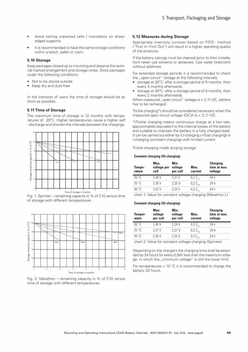
49Mounting and Operating Instructions CEAG Battery Cabinets 40071860035 (P) July 2016 www.ceag.de
5 Transport, Packaging and Storage
• Avoid storing unpacked cells / monoblocs on sharp-edged supports.
• It is recommended to have the same storage conditions within a batch, pallet or room.
5.10 StorageKeep packages closed up to mounting and observe the exter-nal marked arrangement and storage notes. Store packages under the following conditions:
• Not to be stored outside• Keep dry and dust-free
In the interests of users the time of storage should be as short as possible.
Fig. 1: Sprinter – remaining capacity in % of C10 versus time of storage with different temperatures
Fig. 2: Marathon – remaining capacity in % of C10 versus time of storage with different temperatures
5.11 Time of StorageThe maximum time of storage is 12 months with tempe-ratures of 20°C. Higher temperatures cause a higher self - discharge and shorten the intervals between the chargings.
5.12 Measures during StorageAppropriate inventory turnover based on FIFO - method (“First In- First Out”) will result in a higher operating quality of the products.
If the battery casings must be cleaned (prior to their installa-tion) never use solvents or abrasives. Use water (wetcloth) without additives.
For extended storage periods it is recommended to check the „open-circuit“ voltage at the following intervals:• storage at 20°C: after a storage period of 6 months, then
every 3 months afterwards. • storage at 30°C: after a storage period of 4 months, then
every 2 months afterwards.When measured „open circuit“ voltage is < 2,11 V/C, battery has to be recharged.
Trickle charging*) should be considered necessary when the measured open circuit voltage (OCV) is < 2,11 V/C.
*)Trickle charging means continuous charge at a low rate, approximately equivalent to the internal losses of the battery and suitable to maintain the battery in a fully charged state. It can be carried out either by IU-charging (=float charging) or I-charging (constant charging) with limited current.
Trickle charging mode durging storage
Constant charging (IU-charging)
Tempe- rature
Max. voltage per cell
Min. voltage per cell
Max. current
Charging time at max. voltage
20 °C 2,38 V 2,27 V 0,2 C10 24 h
25 °C 2,35 V 2,25 V 0,2 C10 24 h
30 °C 2,32 V 2,22 V 0,2 C10 24 h
chart 1: Value for constant voltage charging (Marathon L)
Constant charging (IU-charging)
Temper- ature
Max. voltage per cell
Min. voltage per cell
Max. current
Charging time at max. voltage
20 °C 2,40 V 2,29 V 0,2 C10 24 h
25 °C 2,37 V 2,27 V 0,2 C10 24 h
30 °C 2,35 V 2,25 V 0,2 C10 24 h
chart 2: Value for constant voltage charging (Sprinter)
Depending on the chargers the charging time shall be exten-ded by 24 hours for every 0,04V less than the maximum volta-ge, in which the „minimum voltage“ is still the lower limit.
For temperatures < 15 °C it is recommended to charge the battery 20 hours.
Aver
age
rem
aini
ng c
apac
ity in
% o
f C10
Aver
age
rem
aini
ng c
apac
ity in
% o
f C10
Time of storage in months
Time of storage in months
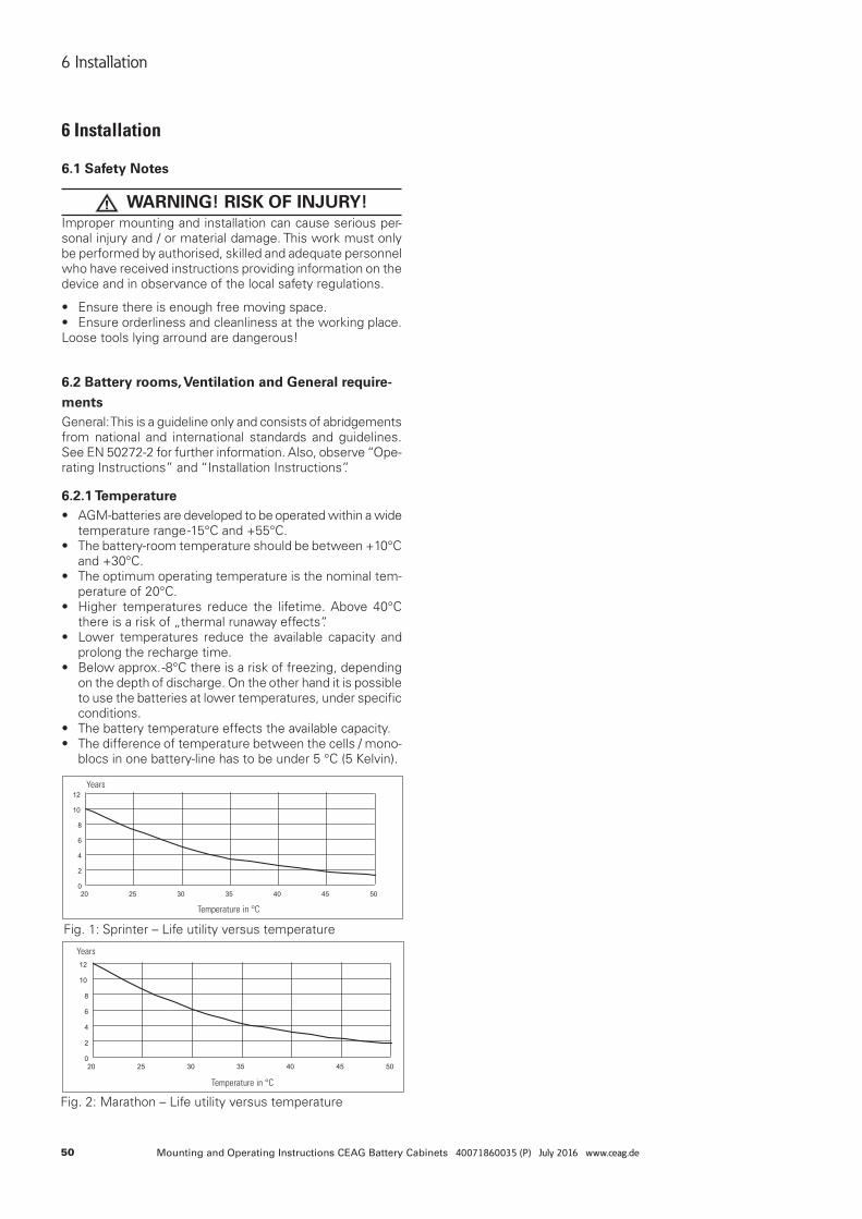
50 Mounting and Operating Instructions CEAG Battery Cabinets 40071860035 (P) July 2016 www.ceag.de
6 Installation
Fig. 1: Sprinter – Life utility versus temperature
Fig. 2: Marathon – Life utility versus temperature
6 Installation
6.1 Safety Notes
WARNING! RISK OF INJURY!Improper mounting and installation can cause serious per-sonal injury and / or material damage. This work must only be performed by authorised, skilled and adequate personnel who have received instructions providing information on the device and in observance of the local safety regulations.
• Ensure there is enough free moving space.• Ensure orderliness and cleanliness at the working place. Loose tools lying arround are dangerous!
6.2 Battery rooms, Ventilation and General require-mentsGeneral: This is a guideline only and consists of abridgements from national and international standards and guidelines. See EN 50272-2 for further information. Also, observe “Ope-rating Instructions” and “Installation Instructions”.
6.2.1 Temperature• AGM-batteries are developed to be operated within a wide
temperature range -15°C and +55°C.• The battery-room temperature should be between +10°C
and +30°C.• The optimum operating temperature is the nominal tem-
perature of 20°C.• Higher temperatures reduce the lifetime. Above 40°C
there is a risk of „thermal runaway effects“.• Lower temperatures reduce the available capacity and
prolong the recharge time.• Below approx. -8°C there is a risk of freezing, depending
on the depth of discharge. On the other hand it is possible to use the batteries at lower temperatures, under specific conditions.
• The battery temperature effects the available capacity.• The difference of temperature between the cells / mono-
blocs in one battery-line has to be under 5 °C (5 Kelvin).
Years
Years
Temperature in °C
Temperature in °C
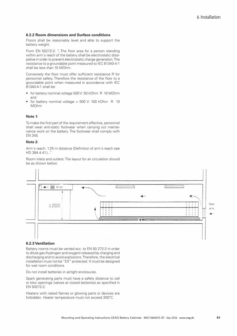
51Mounting and Operating Instructions CEAG Battery Cabinets 40071860035 (P) July 2016 www.ceag.de
6 Installation
6.2.2 Room dimensions and Surface conditionsFloors shall be reasonably level and able to support the battery weight.
From EN 50272-2: “...The floor area for a person standing within arm´s reach of the battery shall be electrostatic dissi-pative in order to prevent electrostatic charge generation. The resistance to a groundable point measured to IEC 61340-4-1 shall be less than 10 MOhm.
Conversely the floor must offer sufficient resistance R for personnel safety. Therefore the resistance of the floor to a groundable point when measured in accordance with IEC 61340-4-1 shall be:
• for battery nominal voltage 500 V: 50 kOhm R 10 MOhm and
• for battery nominal voltage > 500 V: 100 kOhm R 10 MOhm
Note 1:
To make the first part of the requirement effective, personnel shall wear anti-static footwear when carrying out mainte-nance work on the battery. The footwear shall comply with EN 345.
Note 2:
Arm´s reach: 1.25 m distance (Definition of arm´s reach see HD 384.4.41.)...”
Room inlets and outlets: The layout for air circulation should be as shown below:
6.2.3 VentilationBattery rooms must be vented acc. to EN 50 272-2 in order to dilute gas (hydrogen and oxygen) released by charging and discharging and to avoid explosions. Therefore, the electrical installation must not be “EX” protected. It must be designed for wet room conditions.
Do not install batteries in airtight enclosures.
Spark generating parts must have a safety distance to cell or bloc openings (valves at closed batteries) as specified in EN 50272-2.
Heaters with naked flames or glowing parts or devices are forbidden. Heater temperature must not exceed 300°C.
Air out
Clean
air in
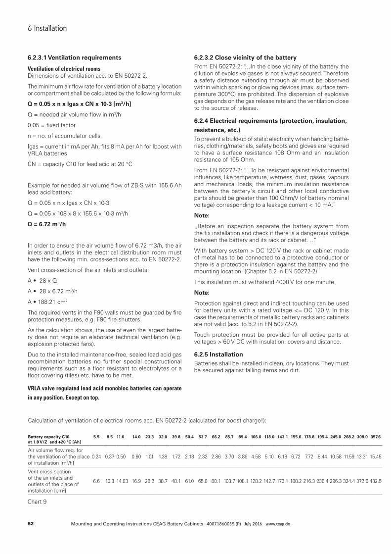
52 Mounting and Operating Instructions CEAG Battery Cabinets 40071860035 (P) July 2016 www.ceag.de
6 Installation
6.2.3.1 Ventilation requirements
Ventilation of electrical roomsDimensions of ventilation acc. to EN 50272-2.
The minimum air flow rate for ventilation of a battery location or compartment shall be calculated by the following formula:
Q = 0.05 x n x Igas x CN x 10-3 [m3/h]
Q = needed air volume flow in m3/h
0.05 = fixed factor
n = no. of accumulator cells
Igas = current in mA per Ah, fits 8 mA per Ah for Iboost with VRLA batteries
CN = capacity C10 for lead acid at 20 °C
Example for needed air volume flow of ZB-S with 155.6 Ah lead acid battery:
Q = 0.05 x n x Igas x CN x 10-3
Q = 0.05 x 108 x 8 x 155.6 x 10-3 m3/h
Q = 6.72 m3/h
In order to ensure the air volume flow of 6.72 m3/h, the air inlets and outlets in the electrical distribution room must have the following min. cross-sections acc. to EN 50272-2.
Vent cross-section of the air inlets and outlets:
A•28xQ
A•28x6.72m3/h
A•188.21cm2
The required vents in the F90 walls must be guarded by fire protection measures, e.g. F90 fire shutters.
As the calculation shows, the use of even the largest batte-ry does not require an elaborate technical ventilation (e.g. explosion protected fans).
Due to the installed maintenance-free, sealed lead acid gas recombination batteries no further special constructional requirements such as a floor resistant to electrolytes or a floor covering (tiles) etc. have to be met.
VRLA valve regulated lead acid monobloc batteries can operate
in any position. Except on top.
Chart 9
Calculation of ventilation of electrical rooms acc. EN 50272-2 (calculated for boost charge!):
6.2.3.2 Close vicinity of the batteryFrom EN 50272-2: “…In the close vicinity of the battery the dilution of explosive gases is not always secured. Therefore a safety distance extending through air must be observed within which sparking or glowing devices (max. surface tem-perature 300°C) are prohibited. The dispersion of explosive gas depends on the gas release rate and the ventilation close to the source of release.
6.2.4 Electrical requirements (protection, insulation, resistance, etc.)To prevent a build-up of static electricity when handling batte-ries, clothing/materials, safety boots and gloves are required to have a surface resistance 108 Ohm and an insulation resistance of 105 Ohm.
From EN 50272-2: “…To be resistant against environmental influences, like temperature, wetness, dust, gases, vapours and mechanical loads, the minimum insulation resistance between the battery´s circuit and other local conductive parts should be greater than 100 Ohm/V (of battery nominal voltage) corresponding to a leakage current < 10 mA.”
Note:
„Before an inspection separate the battery system from the fix installation and check if there is a dangerous voltage between the battery and its rack or cabinet. ...“
With battery system > DC 120 V the rack or cabinet made of metal has to be connected to a protective conductor or there is a protection insulation against the battery and the mounting location. (Chapter 5.2 in EN 50272-2)
This insulation must withstand 4000 V for one minute.
Note:
Protection against direct and indirect touching can be used for battery units with a rated voltage <= DC 120 V. In this case the requirements of metallic battery racks and cabinets are not valid (acc. to 5.2 in EN 50272-2).
Touch protection must be provided for all active parts at voltages > 60 V DC with insulation, covers and distance.
6.2.5 InstallationBatteries shall be installed in clean, dry locations. They must be secured against falling items and dirt.
Battery capacity C10 at 1.8 V/Z and +20 °C [Ah]
5.5 8.5 11.6 14.0 23.3 32.0 39.8 50.4 53.7 66.2 85.7 89.4 106.0 118.0 143.1 155.6 178.8 195.4 245.0 268.2 308.0 357.6
Air volume flow req. for the ventilation of the place of installation [m3/h]
0.24 0.37 0.50 0.60 1.01 1.38 1.72 2.18 2.32 2.86 3.70 3.86 4.58 5.10 6.18 6.72 7.72 8.44 10.58 11.59 13.31 15.45
Vent cross-section of the air inlets and outlets of the place of installation [cm2]
6.6 10.3 14.03 16.9 28.2 38.7 48.1 61.0 65.0 80.1 103.7 108.1 128.2 142.7 173.1 188.2 216.3 236.4 296.3 324.4 372.6 432.5
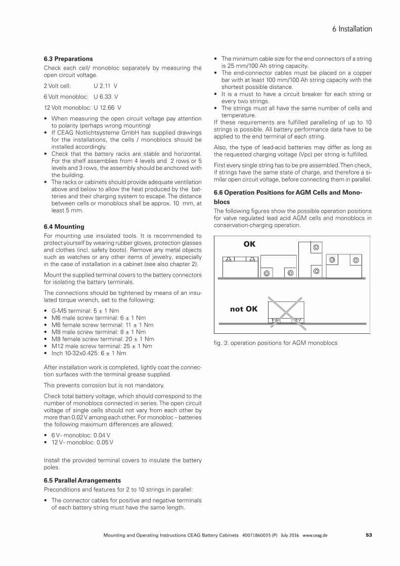
53Mounting and Operating Instructions CEAG Battery Cabinets 40071860035 (P) July 2016 www.ceag.de
6 Installation
6.3 PreparationsCheck each cell/ monobloc separately by measuring the open circuit voltage.
2 Volt cell: U 2.11 V
6 Volt monobloc: U 6.33 V
12 Volt monobloc: U 12.66 V
• When measuring the open circuit voltage pay attention to polarity (perhaps wrong mounting)
• If CEAG Notlichtsysteme GmbH has supplied drawings for the installations, the cells / monoblocs should be installed accordingly.
• Check that the battery racks are stable and horizontal. For the shelf assemblies from 4 levels and 2 rows or 5 levels and 3 rows, the assembly should be anchored with the building.
• The racks or cabinets should provide adequate ventilation above and below to allow the heat produced by the bat-teries and their charging system to escape. The distance between cells or monoblocs shall be approx. 10 mm, at least 5 mm.
6.4 MountingFor mounting use insulated tools. It is recommended to protect yourself by wearing rubber gloves, protection glasses and clothes (incl. safety boots). Remove any metal objects such as watches or any other items of jewelry, especially in the case of installation in a cabinet (see also chapter 2).
Mount the supplied terminal covers to the battery connectors for isolating the battery terminals.
The connections should be tightened by means of an insu-lated torque wrench, set to the following:
• G-M5 terminal: 5 ± 1 Nm• M6 male screw terminal: 6 ± 1 Nm • M6 female screw terminal: 11 ± 1 Nm • M8 male screw terminal: 8 ± 1 Nm • M8 female screw terminal: 20 ± 1 Nm • M12 male screw terminal: 25 ± 1 Nm • Inch 10-32x0.425: 6 ± 1 Nm After installation work is completed, lightly coat the connec-tion surfaces with the terminal grease supplied.
This prevents corrosion but is not mandatory.
Check total battery voltage, which should correspond to the number of monoblocs connected in series. The open circuit voltage of single cells should not vary from each other by more than 0.02 V among each other. For monobloc – batteries the following maximum differences are allowed:
• 6 V - monobloc: 0.04 V• 12 V - monobloc: 0.05 V
Install the provided terminal covers to insulate the battery poles.
6.5 Parallel Arrangements Preconditions and features for 2 to 10 strings in parallel:
• The connector cables for positive and negative terminals of each battery string must have the same length.
• The minimum cable size for the end connectors of a string is 25 mm/100 Ah string capacity.
• The end-connector cables must be placed on a copper bar with at least 100 mm/100 Ah string capacity with the shortest possible distance.
• It is a must to have a circuit breaker for each string or every two strings.
• The strings must all have the same number of cells and temperature.
If these requirements are fulfilled paralleling of up to 10 strings is possible. All battery performance data have to be applied to the end terminal of each string.
Also, the type of lead-acid batteries may differ as long as the requested charging voltage (Vpc) per string is fulfilled.
First every single string has to be pre assembled. Then check, if strings have the same state of charge, and therefore a si-milar open circuit voltage, before connecting them in parallel.
6.6 Operation Positions for AGM Cells and Mono-blocsThe following figures show the possible operation positions for valve regulated lead acid AGM cells and monoblocs in conservation-charging operation.
fig. 3: operation positions for AGM monoblocs
OK
not OK
54 Mounting and Operating Instructions CEAG Battery Cabinets 40071860035 (P) July 2016 www.ceag.de
7 Commissioning
7 Commissioning
Further information about operating can be found in the operating instructions for ZB-S, No. 40071860179.
8 Operating
8.1 Safety Notes
WARNING! RISK OF INJURY!Improper mounting and installation can cause serious perso-nal injury and / or material damage.This work must only be performed by authorised , skilled and adequate personnel who have received instructions providing information on the device and in observance of the local safety regulations.
• Before work begins: • Before work on the battery begins check its completeness
and technical correctness. • Ensure there is enough free moving space.
ATTENTION! Please do not stick the battery block numbers over the battery block valve cover.
During operation:
• When failures arise first of all switch battery off and pro-tect against reengagement.
When working on and with the battery it is necessary to wear:
• Safety boots which protect against falling parts and against slipping on non – anti – slip floor.
9 Maintenance
9.1 Safety Notes
WARNING! RISK OF INJURY!Improper maintenance work can cause serious personal in-jury and / or material damage. This work has to be performed only by authorised, skilled and adequate personnel who have received instructions providing information on the device and in observance of local safety regulations.
9.2 Maintenance
ATTENTION! MATERIAL DAMAGE!Never use a synthetic cloth or sponge to clean cells / mono-blocs. Use water (wet cloth) without additives.
9.2.1 General Items and Checks (acc. to Operating Instructions/Appendix)Periodic inspections and maintenance are necessary regar-ding:
• charge voltage and current settings,• the discharge conditions,• the temperature levels,
• the storage conditions,• the cleanliness of the battery and equipment• and other conditions relevant to safety issues and battery´s
service life (battery room ventilation, for example). Periodic discharges can be used to assess the available operating endurance, to detect faulty cells/monoblocs and ageing symptoms of the battery, in order to consider battery replacement in due time.
VRLA (Valve-Regulated Lead-Acid Batteries) batteries do not require topping-up with water. That´s the reason why they were called ”maintenance-free“. Pressure valves are used for sealing and cannot be opened without destruction. Therefore, they are defined as ”Valve-Regulated“ lead-acid batteries (VRLA-batteries).
Even if VRLA-batteries are called ”maintenance-free“ they sometimes need inspection (see ”Operating Instructions“ for details):
At least every 6 months measure and record:
• Battery voltage• Voltage of several cells/blocs (approx. 20%)• Surface temperature of several cells/blocs• Battery-room temperature
Annual visual check:
• bolted assemblies (checking unsecure bolted assemblies to adjust them)
• Battery rack and accommodation ventilation
If the cell/bloc voltages differ from the average float charge voltage by more than a specified +/- tolerance as stated in table 7 or if the surface temperature difference between cells/blocs exceeds 5 K, the service agent should be contacted.
9.2.2 Cleaning of BatteriesIt is not allowed to open valves and covers.
Never use a synthetic cloth or sponge to clean the cells and plastic parts of the battery. Use water (wet cloth) without additives.
After cleaning the battery cover has to be dried, e. g. with compressed air or cleaning cloth.
Operation since 6-V-monoblocs 12-V-monoblocsk
6.81 V 13.62 V
< 6 months 6.60 - 7.19 V 13.33 - 14.16 V
> 6 months 6.64 - 7.16 V 13.38 - 14.11 V
chart 7: Valid range of conservation charging voltage
55Mounting and Operating Instructions CEAG Battery Cabinets 40071860035 (P) July 2016 www.ceag.de
10 Failures
10 Failures
10.1 Reaction to FailureFurther information about failures can be found in the ope-rating instructions for ZB-S, No. 40071860179.
11 Spare parts
Only use original spare parts from the manufacturer.
ATTENTION!Wrong or faulty spare parts from other manufacturers can cause serious damage to the battery. Ensure the same char-ging state when changing the battery blocs.
RECOMMENDATION:not more than 25% of the battery packs of a battery set should be replaced. Therefore with 18 packs not more than 5 packs should be replaced.
When 50% of the expected service life is exceeded and single battery packs fail, the complete set should be replaced
11.1 Ordering Spare PartsPlease state the following when ordering spare parts:
– order number– rated capacity –type
In case of complaints you need a RMA - number from us. For further information see www.ceag.de!
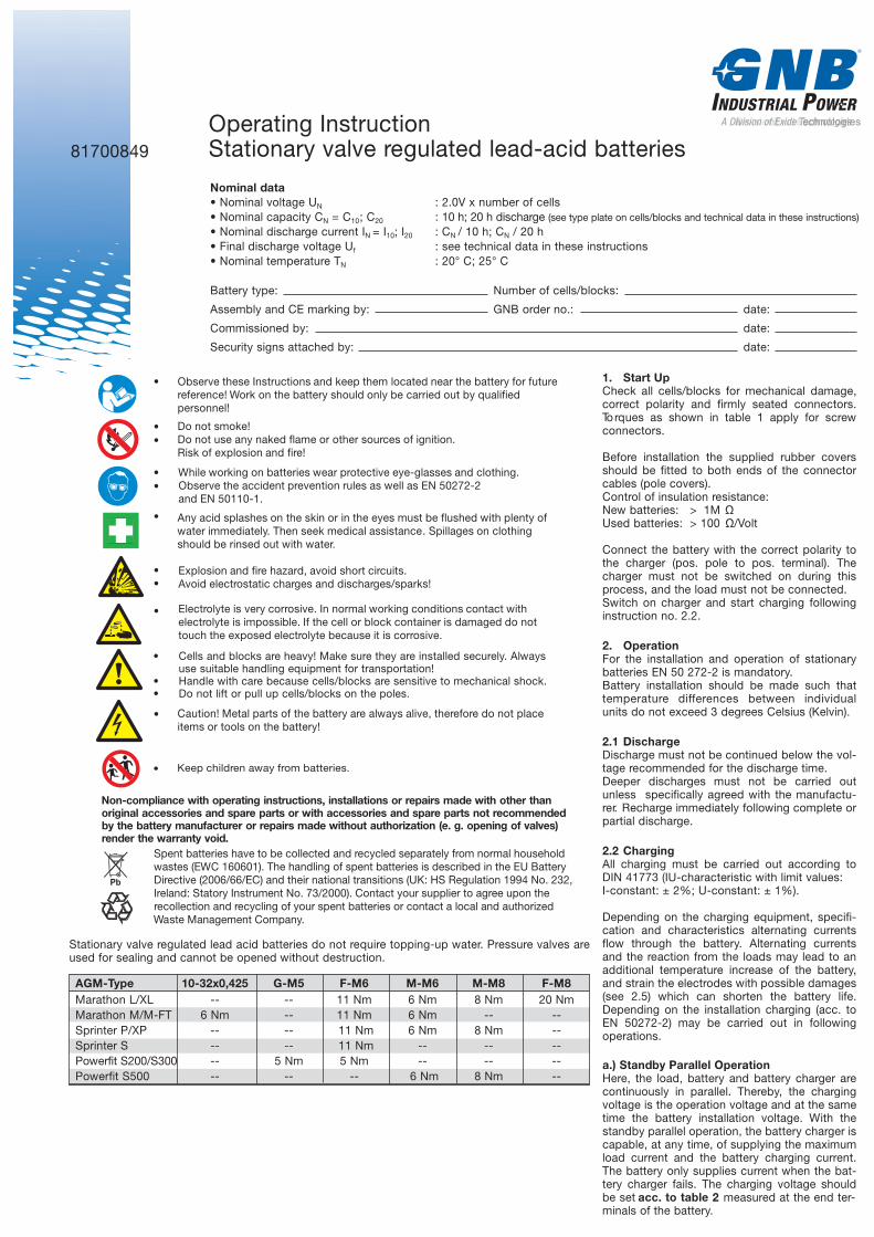
56 Mounting and Operating Instructions CEAG Battery Cabinets 40071860035 (P) July 2016 www.ceag.de
7 Commissioning
Pb
•
•
•
•
•
•
•
•
•
•
•
•
•
Observe these Instructions and keep them located near the battery for future
reference! Work on the battery should only be carried out by qualified
personnel!
Do not smoke!
Do not use any naked flame or other sources of ignition.
Risk of explosion and fire!
While working on batteries wear protective eye-glasses and clothing.
Observe the accident prevention rules as well as EN 50272-2
and EN 50110-1.
Any acid splashes on the skin or in the eyes must be flushed with plenty of
water immediately. Then seek medical assistance. Spillages on clothing
should be rinsed out with water.
Explosion and fire hazard, avoid short circuits.
Avoid electrostatic charges and discharges/sparks!
Cells and blocks are heavy. Always use suitable handling equipment for
transportation.
Handle with care because cells/blocks are sensitive to mechanical shock.
Do not lift or pull up cells/blocks on the poles.
Caution! Metal parts of the battery are always alive, therefore do not place
items or tools on the battery!
Electrolyte is very corrosive. In normal working conditions contact with
electrolyte is impossible. If the cell or block container is damaged do not
touch the exposed electrolyte because it is corrosive.
Non-compliance with operating instructions, installations or repairs made with other than
original accessories and spare parts or with accessories and spare parts not recommended
by the battery manufacturer or repairs made without authorization (e. g. opening of valves)
render the warranty void.
Spent batteries have to be collected and recycled separately from normal household
wastes (EWC 160601). The handling of spent batteries is described in the EU Battery
Directive (2006/66/EC) and their national transitions (UK: HS Regulation 1994 No. 232,
Ireland: Statory Instrument No. 73/2000). Contact your supplier to agree upon the
recollection and recycling of your spent batteries or contact a local and authorized
Waste Management Company.
•
Keep children away from batteries.
81700849
Operating Instruction
Stationary valve regulated lead-acid batteries
AD ivisio noEf xideTechnologiesTTechnologies
Nominal data
• Nominal voltage U
N
: 2.0V x number of cells
• Nominal capacity C
N
= C
10
; C
20
: 10 h; 20 h discharge (see type plate on cells/blocks and technical data in these instructions)
• Nominal discharge current I
N
= I
10
; I
20
: C
N
/ 10 h; C
N
/ 20 h
• Final discharge voltage U
f
: see technical data in these instructions
• Nominal temperature T
N
: 20° C; 25° C
Battery type: Number of cells/blocks:
Assembly and CE marking by: GNB order no.: date:
Commissioned by: date:
Security signs attached by: date:
1. Start Up
Check all cells/blocks for mechanical damage,
correct polarity and firmly seated connectors.
Torques as shown in table 1 apply for screw
connectors.
Before installation the supplied rubber covers
should be fitted to both ends of the connector
cables (pole covers).
Control of insulation resistance:
New batteries: > 1M Ù
Used batteries: > 100 Ù / Volt
Connect the battery with the correct polarity to
the charger (pos. pole to pos. terminal). The
charger must not be switched on during this
process, and the load must not be connected.
Switch on charger and start charging following
instruction no. 2.2.
2. Operation
For the installation and operation of stationary
batteries EN 50 272-2 is mandatory.
Battery installation should be made such that
temperature differences between individual
units do not exceed 3 degrees Celsius (Kelvin).
2.1 Discharge
Discharge must not be continued below the vol-
tage recommended for the discharge time.
Deeper discharges must not be carried out
unless specifically agreed with the manufactu-
rer. Recharge immediately following complete or
partial discharge.
2.2 Charging
All charging must be carried out according to
DIN 41773 (IU-characteristic with limit values:
I-constant: ± 2%; U-constant: ± 1%).
Depending on the charging equipment, specifi-
cation and characteristics alternating currents
flow through the battery. Alternating currents
and the reaction from the loads may lead to an
additional temperature increase of the battery,
and strain the electrodes with possible damages
(see 2.5) which can shorten the battery life.
Depending on the installation charging (acc. to
EN 50272-2) may be carried out in following
operations.
a.) Standby Parallel Operation
Here, the load, battery and battery charger are
continuously in parallel. Thereby, the charging
voltage is the operation voltage and at the same
time the battery installation voltage. With the
standby parallel operation, the battery charger is
capable, at any time, of supplying the maximum
load current and the battery charging current.
The battery only supplies current when the bat-
tery charger fails. The charging voltage should
be set a cc. to table 2 m easured at the end ter-
minals of the battery.
Stationary valve regulated lead acid batteries do not require topping-up water. Pressure valves are
used for sealing and cannot be opened without destruction.
AGM-Type 10-32x0,425 G-M5 F-M6 M-M6 M-M8 F-M8
Marathon L/XL -- -- 11 Nm 6 Nm 8 Nm 20 Nm
Marathon M/M-FT 6 Nm -- 11 Nm 6 Nm -- --
Sprinter P/XP -- -- 11 Nm 6 Nm 8 Nm --
Sprinter S -- -- 11 Nm -- -- --
Powerfit S200/S300 -- 5 Nm 5 Nm -- -- --
Powerfit S500 -- -- -- 6 Nm 8 Nm --
• Cells and blocks are heavy! Make sure they are installed securely. Always
use suitable handling equipment for transportation!
• Handle with care because cells/blocks are sensitive to mechanical shock.
• Do not lift or pull up cells/blocks on the poles.
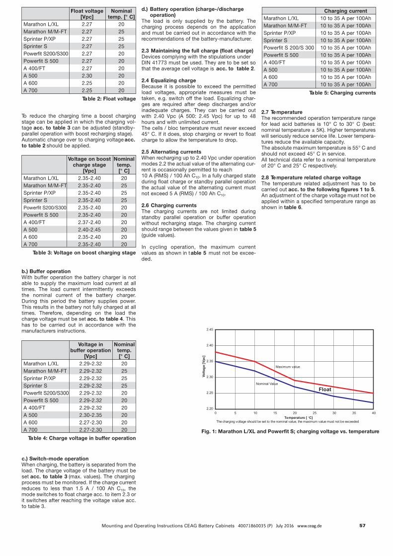
57Mounting and Operating Instructions CEAG Battery Cabinets 40071860035 (P) July 2016 www.ceag.de
7 Commissioning
To reduce the charging time a boost charging
stage can be applied in which the charging vol-
tage acc. to table 3 c a n be adjusted (standby-
parallel operation with boost recharging stage).
Automatic change over to charging voltage a c c .
to table 2 s hould be applied.
b.) Buffer operation
With buffer operation the battery charger is not
able to supply the maximum load current at all
times. The load current intermittently exceeds
the nominal current of the battery charger.
During this period the battery supplies power.
This results in the battery not fully charged at all
times. Therefore, depending on the load the
charge voltage must be set a c c. to table 4. This
has to be carried out in accordance with the
manufacturers instructions.
c.) Switch-mode operation
When charging, the battery is separated from the
load. The charge voltage of the battery must be
set acc. to table 3 ( m ax. values). The charging
process must be monitored. If the charge current
reduces to less than 1.5 A / 100 Ah C
10
, the
mode switches to float charge acc. to item 2.3 or
it switches after reaching the voltage value acc.
to table 3.
Float voltage Nominal
[Vpc] temp. [° C]
Marathon L/XL 2.27 20
Marathon M/M-FT 2.27 25
Sprinter P/XP 2.27 25
Sprinter S 2.27 25
Powerfit S200/S300 2.27 20
Powerfit S 500 2.27 20
A 400/FT 2.27 20
A 500 2.30 20
A 600 2.25 20
A 700 2.25 20
Table 2: Float voltage
Voltage on boost Nominal
charge stage temp.
[Vpc] [° C]
Marathon L/XL 2.35-2.40 20
Marathon M/M-FT 2.35-2.40 25
Sprinter P/XP 2.35-2.40 25
Sprinter S 2.35-2.40 25
Powerfit S200/S300 2.35-2.40 20
Powerfit S 500 2.35-2.40 20
A 400/FT 2.37-2.40 20
A 500 2.40-2.45 20
A 600 2.35-2.40 20
A 700 2.35-2.40 20
Table 3: Voltage on boost charging stage
Charging current
Marathon L/XL 10 to 35 A per 100Ah
Marathon M/M-FT 10 to 35 A per 100Ah
Sprinter P/XP 10 to 35 A per 100Ah
Sprinter S 10 to 35 A per 100Ah
Powerfit S 200/S 300 10 to 35 A per 100Ah
Powerfit S 500 10 to 35 A per 100Ah
A 400/FT 10 to 35 A per 100Ah
A 500 10 to 35 A per 100Ah
A 600 10 to 35 A per 100Ah
A 700 10 to 35 A per 100Ah
Table 5: Charging currents
Voltage in Nominal
buffer operation temp.
[Vpc] [° C]
Marathon L/XL 2.29-2.32 20
Marathon M/M-FT 2.29-2.32 25
Sprinter P/XP 2.29-2.32 25
Sprinter S 2.29-2.32 25
Powerfit S200/S300 2.29-2.32 20
Powerfit S 500 2.29-2.32 20
A 400/FT 2.29-2.32 20
A 500 2.30-2.35 20
A 600 2.27-2.30 20
A 700 2.27-2.30 20
Table 4: Charge voltage in buffer operation
d.) Battery operation (charge-/discharge
operation)
The load is only supplied by the battery. The
charging process depends on the application
and must be carried out in accordance with the
recommendations of the battery-manufacturer.
2.3 Maintaining the full charge (float charge)
Devices complying with the stipulations under
DIN 41773 must be used. They are to be set so
that the average cell voltage is a c c . to table 2.
2.4 Equalizing charge
Because it is possible to exceed the permitted
load voltages, appropriate measures must be
taken, e.g. switch off the load. Equalizing char-
ges are required after deep discharges and/or
inadequate charges. They can be carried out
with 2.40 Vpc (A 500: 2.45 Vpc) for up to 48
hours and with unlimited current.
The cells / bloc temperature must never exceed
45° C. If it does, stop charging or revert to float
charge to allow the temperature to drop.
2.5 Alternating currents
When recharging up to 2.40 Vpc under operation
modes 2.2 the actual value of the alternating cur-
rent is occasionally permitted to reach
10 A (RMS) / 100 Ah C
10
. In a fully charged state
during float charge or standby parallel operation
the actual value of the alternating current must
not exceed 5 A (RMS) / 100 Ah C
10
.
2.6 Charging currents
The charging currents are not limited during
standby parallel operation or buffer operation
without recharging stage. The charging current
should range between the values given in t a b le 5
(guide values).
In cycling operation, the maximum current
values as shown in t a ble 5 m ust not be excee-
ded.
2.7 Temperature
The recommended operation temperature range
for lead acid batteries is 10° C to 30° C (best:
nominal temperature ± 5K). Higher temperatures
will seriously reduce service life. Lower tempera-
tures reduce the available capacity.
The absolute maximum temperature is 55° C and
should not exceed 45° C in service.
All technical data refer to a nominal temperature
of 20° C and 25° C respectively.
2.8 Temperature related charge voltage
The temperature related adjustment has to be
carried out a cc. to the following figures 1 to 5.
An adjustment of the charge voltage must not be
applied within a specified temperature range as
shown in t able 6.
2.20
2.25
2.30
2.35
2.40
2.45
0 5 10 15 20 25 30 35 40
Temperature [ C]
Vo
lta
ge
[V
pc
]
Nominal Value
The charging voltage should be set to the nominal value, the maximum value must not be exceeded
Maximum value
Float
Fig. 1: Marathon L/XL and Powerfit S; charging voltage vs. temperature
2
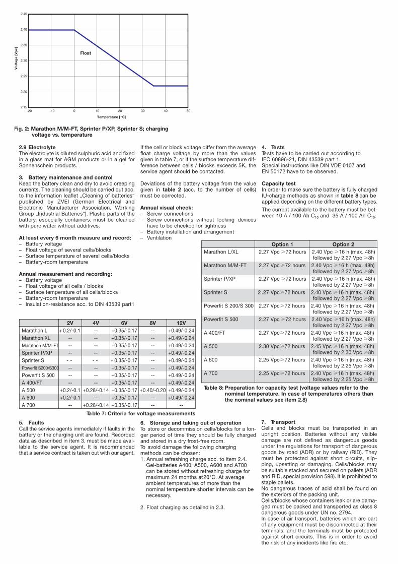
58 Mounting and Operating Instructions CEAG Battery Cabinets 40071860035 (P) July 2016 www.ceag.de
7 Commissioning
2.9 Electrolyte
The electrolyte is diluted sulphuric acid and fixed
in a glass mat for AGM products or in a gel for
Sonnenschein products.
3. Battery maintenance and control
Keep the battery clean and dry to avoid creeping
currents. The cleaning should be carried out acc.
to the information leaflet „Cleaning of batteries“
published by ZVEI (German Electrical and
Electronic Manufacturer Association, Working
Group „Industrial Batteries“). Plastic parts of the
battery, especially containers, must be cleaned
with pure water without additives.
At least every 6 month measure and record:
– Battery voltage
– Float voltage of several cells/blocks
– Surface temperature of several cells/blocks
– Battery-room temperature
Annual measurement and recording:
– Battery voltage
– Float voltage of all cells / blocks
– Surface temperature of all cells/blocks
– Battery-room temperature
– Insulation-resistance acc. to DIN 43539 part1
2V 4V 6V 8V 12V
Marathon L + 0.2/-0.1 -- +0.35/-0.17 -- +0.49/-0.24
Marathon XL -- -- +0.35/-0.17 -- +0.49/-0.24
Marathon M/M-FT -- -- +0.35/-0.17 -- +0.49/-0.24
Sprinter P/XP -- -- +0.35/-0.17 -- +0.49/-0.24
Sprinter S - - - - + 0.35/-0.17 -- +0.49/-0.24
Powerfit S200/S300 -- -- +0.35/-0.17 -- +0.49/-0.24
Powerfit S 500 -- -- +0.35/-0.17 -- +0.49/-0.24
A 400/FT -- -- +0.35/-0.17 -- +0.49/-0.24
A 500 +0.2/-0.1 +0.28/-0.14 +0.35/-0.17 +0.40/-0.20 +0.49/-0.24
A 600 +0.2/-0.1 -- +0.35/-0.17 -- +0.49/-0.24
A 700 -- +0.28/-0.14 +0.35/-0.17 -- --
Table 7: Criteria for voltage measurements
Option 1 Option 2
Marathon L/XL 2.27 Vpc ≥ 7 2 h o u r s 2.40 Vpc ≥ 1 6 h (max. 48h)
followed by 2.27 Vpc ≥ 8h
Marathon M/M-FT 2.27 Vpc ≥ 7 2 h ours 2.40 Vpc ≥ 1 6 h (max. 48h)
followed by 2.27 Vpc ≥ 8h
Sprinter P/XP 2.27 Vpc ≥ 7 2 h o u r s 2.40 Vpc ≥ 1 6 h (max. 48h)
followed by 2.27 Vpc ≥ 8h
Sprinter S 2 .27 Vpc≥ 72 hours 2.40 Vpc ≥ 1 6 h (max. 48h)
followed by 2.27 Vpc ≥ 8h
Powerfit S 200/S 300 2.27 Vpc≥ 7 2 hours 2.40 Vpc ≥ 1 6 h (max. 48h)
followed by 2.27 Vpc ≥ 8h
Powerfit S 500 2.27 Vpc ≥ 7 2 h o u r s 2.40 Vpc ≥ 1 6 h (max. 48h)
followed by 2.27 Vpc ≥ 8h
A 400/FT 2.27 Vpc≥ 72 hours 2.40 Vpc ≥ 1 6 h (max. 48h)
followed by 2.27 Vpc ≥ 8h
A 500 2.30 Vpc≥ 72 hours 2.45 Vpc ≥ 1 6 h (max. 48h)
followed by 2.30 Vpc ≥ 8h
A 600 2.25 Vpc≥ 72 hours 2.40 Vpc ≥ 1 6 h (max. 48h)
followed by 2.25 Vpc ≥ 8h
A 700 2.25 Vpc≥ 72 hours 2.40 Vpc ≥ 1 6 h (max. 48h)
followed by 2.25 Vpc ≥ 8h
Table 8: Preparation for capacity test (voltage values refer to the
nominal temperature. In case of temperatures others than
the nominal values see item 2.8)
If the cell or block voltage differ from the average
float charge voltage by more than the values
given in table 7, or if the surface temperature dif-
ference between cells / blocks exceeds 5K, the
service agent should be contacted.
Deviations of the battery voltage from the value
given in table 2 (acc. to the number of cells)
must be corrected.
Annual visual check:
– Screw-connections
– Screw-connections without locking devices
have to be checked for tightness
– Battery installation and arrangement
– Ventilation
4. Tests
Tests have to be carried out according to
IEC 60896-21, DIN 43539 part 1.
Special instructions like DIN VDE 0107 and
EN 50172 have to be observed.
Capacity test
In order to make sure the battery is fully charged
IU-charge methods as shown in t a b le 8 c an be
applied depending on the different battery types.
The current available to the battery must be bet-
ween 10 A / 100 Ah C
10
and 35 A / 100 Ah C
10
.
5. Faults
Call the service agents immediately if faults in the
battery or the charging unit are found. Recorded
data as described in item 3. must be made avai-
lable to the service agent. It is recommended
that a service contract is taken out with our agent.
6. Storage and taking out of operation
To store or decommission cells/blocks for a lon-
ger period of time they should be fully charged
and stored in a dry frost-free room.
To avoid damage the following charging
methods can be chosen:
1. Annual refreshing charge acc. to item 2.4.
Gel-batteries A400, A500, A600 and A700
can be stored without refreshing charge for
maximum 24 months≤at20°C. At average
ambient temperatures of more than the
nominal temperature shorter intervals can be
necessary.
2. Float charging as detailed in 2.3.
7. Transport
Cells and blocks must be transported in an
upright position. Batteries without any visible
damage are not defined as dangerous goods
under the regulations for transport of dangerous
goods by road (ADR) or by railway (RID). They
must be protected against short circuits, slip-
ping, upsetting or damaging. Cells/blocks may
be suitable stacked and secured on pallets (ADR
and RID, special provision 598). It is prohibited to
staple pallets.
No dangerous traces of acid shall be found on
the exteriors of the packing unit.
Cells/blocks whose containers leak or are dama-
ged must be packed and transported as class 8
dangerous goods under UN no. 2794.
In case of air transport, batteries which are part
of any equipment must be disconnected at their
terminals, and the terminals must be protected
against short-circuits. This is in order to avoid
the risk of any incidents like fire etc.
2.15
2.20
2.25
2.30
2.35
2.40
2.45
-20 -10 0 10 20 30 40 50
Temperature [°C]
Vo
ltag
e[V
pc]
Float
Fig. 2: Marathon M/M-FT, Sprinter P/XP, Sprinter S; chargingvoltage vs. temperature

59Mounting and Operating Instructions CEAG Battery Cabinets 40071860035 (P) July 2016 www.ceag.de
Eaton is a registered trademark.
All other trademarks are the property of their respective owners.
Eaton Industries Manufacturing GmbHElectrical Sector EMEARoute de la Longeraie 7 1110 Morges, SwitzerlandEaton.eu
CEAG Notlichtsysteme GmbHSenator-Schwartz-Ring 2659494 Soest, GermanyTel.: +49 (0) 2921 69-870Fax: +49 (0) 2921 69-617E-Mail: [email protected] Web: www.ceag.de
© 2016 EatonAll righs reservedPrinted in GermanyPublication No. MN451004ENOrder no. 40071860035 (P)July 2016
The aim of Eaton is to provide a reliable, efficient and safe power supply where it is needed most. Eaton's experts have comprehensive in-depth specialist knowledge in the area of energy management in the most diverse of sectors and therefore they are able to provide customer-specific, inte-grated solutions to meet the most challenging demands of its customers.
It is our highest priority always to find the right solution for every application. Our stakeholders therefore expect more than just innovative products. Companies turn to Eaton because they know that individual support and the success of our customers is always our top priority. For more information visit www.eaton.eu.
You will find your contact partner at www.ceag.de.